852-1411 - Switch Wago - Free user manual and instructions
Find the device manual for free 852-1411 Wago in PDF.


| Product Type | Switch |
| Brand | Wago |
| Model | 852-1411 |
| Dimensions (H x W x D) | Approx. 50 x 25 x 22 mm |
| Weight | Approx. 30 g |
| Rated Voltage | 250 V AC |
| Rated Current | 10 A |
| Contact Configuration | SPDT (Single Pole Double Throw) |
| Actuation Type | Pushbutton |
| Mounting Type | Panel mount |
| Terminal Type | Screw terminals |
| IP Rating | IP20 |
| Material | Plastic housing, copper contacts |
| Operating Temperature | -25 °C to +55 °C |
| Mechanical Life | 100,000 cycles |
| Electrical Life | 10,000 cycles at rated load |
| Functions | ON/OFF switching, momentary or latching |
| Maintenance | Clean with dry cloth; no lubrication required |
| Safety | CE marked, RoHS compliant |
| Spare Parts / Repairability | Non-repairable; replace unit if faulty |
| Certifications | CE, UL, CSA (depending on variant) |
Frequently Asked Questions - 852-1411 Wago
User questions about 852-1411 Wago
0 question about this device. Answer the ones you know or ask your own.
Ask a new question about this device
Download the instructions for your Switch in PDF format for free! Find your manual 852-1411 - Wago and take your electronic device back in hand. On this page are published all the documents necessary for the use of your device. 852-1411 by Wago.
USER MANUAL 852-1411 Wago
WAGO ETHERNET Accessories 852

natural_image
Black industrial network switch device with four ports and a small terminal block (no visible text or symbols)852-1411
Industrial Eco Switch
5 Ports 1000BASE-T, 4 x PoE, EXT
All rights reserved.
Every conceivable measure has been taken to ensure the accuracy and completeness of this documentation. However, as errors can never be fully excluded, we always appreciate any information or suggestions for improving the documentation.
E-Mail: documentation@wago.com
We wish to point out that the software and hardware terms as well as the trademarks of companies used and/or mentioned in the present manual are generally protected by trademark or patent.
WAGO is a registered trademark of WAGO Verwaltungsgesellschaft mbH.
Table of Contents
1 Notes about this Documentation ....5
1.1 Validity of this Documentation....5
1.2 Copyright....5
1.3 Symbols 6
1.4 Number Notation 8
1.5 Font Conventions 8
2 Important Notes 9
2.1 Legal Bases....9
2.1.1 Subject to Changes....9
2.1.2 Personnel Qualification 9
2.1.3 Proper Use of the Industrial Switches 9
2.1.4 Technical Condition of Specified Devices....9
2.1.5 Standards and Regulations for Operating the Industrial Switches ....11
2.2 Safety Advice (Precautions) 12
2.3 Special Use Conditions for ETHERNET Devices....14
3 General 15
3.1 Package Contents ....15
3.2 Industrial ETHERNET Technology 15
3.3 Switching Technology....15
3.4 PoE (Power over Ethernet)....16
3.5 Autonegotiation 17
3.6 Autocrossing....17
3.7 Store-and-forward switching mode 18
3.8 Transmission Methods....18
4 Device Description....19
4.1 View 20
4.1.1 Front View....20
4.1.2 Top View....21
4.2 Connectors....22
4.2.1 Grounding screw....22
4.2.2 Power Supply (PWR/RPS) 23
4.2.3 Network Connections....24
4.2.3.1 10/100/1000BASE-T ports with PoE+....24
4.2.3.2 10/100/1000Base-T ports 25
4.3 Display Elements....26
4.3.1 Device LED....26
4.3.2 Port LEDs 27
4.4 Label 28
4.4.1 Hardware and Software Version 28
4.5 Technical Data 29
4.5.1 Device Data 29
4.5.2 System Data 29
4.5.3 Power Supply....29
4.5.4 Communication....29
4.5.5 Environmental Conditions 30
4.6 Approvals ....31
5 Mounting....32
5.1 Installation site....32
5.2 Installation on a DIN Rail 32
5.3 Removal from DIN Rail 33
6 Connect Devices ....34
6.1 Power Supply 34
7 Appendix ....35
7.1 RJ-45 Cable 35
7.2 PoE (Power over Ethernet) Performance Classes 36
List of Figures ......37
List of Tables....38
1 Notes about this Documentation

Note
Always retain this documentation!
This documentation is part of the product. Therefore, retain the documentation during the entire service life of the product. Pass on the documentation to any subsequent user. In addition, ensure that any supplement to this documentation is included, if necessary.
1.1 Validity of this Documentation
This documentation is only applicable to WAGO ETHERNET accessory products "Industrial Eco Switch" (852-1411).
This documentation is only applicable from .
1.2 Copyright
This Manual, including all figures and illustrations, is copyright-protected. Any further use of this Manual by third parties that violate pertinent copyright provisions is prohibited. Reproduction, translation, electronic and phototechnical filing/archiving (e.g., photocopying) as well as any amendments require the written consent of WAGO Kontakttechnik GmbH & Co. KG, Minden, Germany. Non-observance will involve the right to assert damage claims.
1.3 Symbols

DANGER
Personal Injury!
Indicates a high-risk, imminently hazardous situation which, if not avoided, will result in death or serious injury.


DANGER
Personal Injury Caused by Electric Current!
Indicates a high-risk, imminently hazardous situation which, if not avoided, will result in death or serious injury.

WARNING
Personal Injury!
Indicates a moderate-risk, potentially hazardous situation which, if not avoided, could result in death or serious injury.

CAUTION
Personal Injury!
Indicates a low-risk, potentially hazardous situation which, if not avoided, may result in minor or moderate injury.
NOTICE
Damage to Property!
Indicates a potentially hazardous situation which, if not avoided, may result in damage to property.

NOTICE
Damage to Property Caused by Electrostatic Discharge (ESD)!
Indicates a potentially hazardous situation which, if not avoided, may result in damage to property.

Note
Important Note!
Indicates a potential malfunction which, if not avoided, however, will not result in damage to property.

Information
Additional Information:
Refers to additional information which is not an integral part of this documentation (e.g., the Internet).
1.4 Number Notation
Table 1: Number Notation
| Number Code | Example | Note |
| Decimal | 100 | Normal notation |
| Hexadecimal | 0x64 | C notation |
| Binary | '100' '0110.0100' | In quotation marks, nibble separated with dots (.) |
1.5 Font Conventions
Table 2: Font Conventions
| Font Type | Indicates |
| italic | Names of paths and data files are marked in italic-type.e.g.: C:\Program Files\WAGO Software |
| Menu | Menu items are marked in bold letters.e.g.: Save |
| > | A greater-than sign between two names means the selection of a menu item from a menu.e.g.: File > New |
| Input | Designation of input or optional fields are marked in bold letters,e.g.: Start of measurement range |
| “Value” | Input or selective values are marked in inverted commas.e.g.: Enter the value “4 mA” under Start of measurement range. |
| [Button] | Pushbuttons in dialog boxes are marked with bold letters in square brackets.e.g.: [Input] |
| [Key] | Keys are marked with bold letters in square brackets.e.g.: [F5] |
2 Important Notes
This section includes an overall summary of the most important safety requirements and notes that are mentioned in each individual section. To protect your health and prevent damage to devices as well, it is imperative to read and carefully follow the safety guidelines.
2.1 Legal Bases
2.1.1 Subject to Changes
WAGO Kontakttechnik GmbH & Co. KG reserves the right to provide for any alterations or modifications. WAGO Kontakttechnik GmbH & Co. KG owns all rights arising from the granting of patents or from the legal protection of utility patents. Third-party products are always mentioned without any reference to patent rights. Thus, the existence of such rights cannot be excluded.
2.1.2 Personnel Qualification
All sequences implemented on Series 852 devices may only be carried out by electrical specialists with sufficient knowledge in automation. The specialists must be familiar with the current norms and guidelines for the devices and automated environments.
All changes to the controller should always be carried out by qualified personnel with sufficient sufficient skills in PLC programming.
2.1.3 Proper Use of the Industrial Switches
The device is designed for the IP30 protection class. It is protected against the insertion of solid items and solid impurities up to 2.5 mm in diameter, but not against water penetration. Unless otherwise specified, the device must not be operated in wet and dusty environments.
2.1.4 Technical Condition of Specified Devices
The devices to be supplied ex works are equipped with hardware and software configurations, which meet the individual application requirements. These modules contain no parts that can be serviced or repaired by the user. The following actions will result in the exclusion of liability on the part of WAGO Kontakttechnik GmbH & Co. KG:
- Repairs,
- Changes to the hardware or software that are not described in the operating instructions,
- Improper use of the components.
Further details are given in the contractual agreements. Please send your request for modified and new hardware or software configurations directly to WAGO Kontakttechnik GmbH & Co. KG.
2.1.5 Standards and Regulations for Operating the Industrial Switches
Please observe the standards and regulations that are relevant to installation:
- The data and power lines must be connected and installed in compliance with the standards to avoid failures on your installation and eliminate any danger to personnel.
- For installation, startup, maintenance and repair, please observe the accident prevention regulations of your machine (e.g., DGUV Regulation "Electrical Installations and Equipment").
- Emergency stop functions and equipment must not be deactivated or otherwise made ineffective. See relevant standards (e.g., EN 418).
- Your installation must be equipped in accordance to the EMC guidelines so electromagnetic interferences can be eliminated.
- Please observe the safety measures against electrostatic discharge according to EN 61340-5-1/-3. When handling the modules, ensure that environmental factors (persons, workplace and packing) are well grounded.
- The relevant valid and applicable standards and guidelines regarding the installation of switch cabinets must be observed.
2.2 Safety Advice (Precautions)
For installing and operating purposes of the relevant device to your system the following safety precautions shall be observed:


DANGER
Do not work on devices while energized!
All power sources to the device shall be switched off prior to performing any installation, repair or maintenance work.

DANGER
Only install in appropriate housings, cabinets or electrical operation rooms!
WAGO's 852 Series ETHERNET Switches are considered exposed operating components. Therefore, only install these switches in lockable housings, cabinets or electrical operation rooms. Access must be limited to authorized, qualified staff having the appropriate key or tool.

DANGER
Ensure a standard connection!
To minimize any hazardous situations resulting in personal injury or to avoid failures in your system, the data and power supply lines shall be installed according to standards, with careful attention given to ensuring the correct terminal assignment. Always adhere to the EMC directives applicable to your application.
NOTICE
Do not use in telecommunication circuits!
Only use devices equipped with ETHERNET or RJ-45 connectors in LANs. Never connect these devices with telecommunication networks.
NOTICE
Replace defective or damaged devices!
Replace defective or damaged device/module (e.g., in the event of deformed contacts).
NOTICE
Protect the components against materials having seeping and insulating properties!
The components are not resistant to materials having seeping and insulating properties such as: aerosols, silicones and triglycerides (found in some hand creams). If you cannot exclude that such materials will appear in the component environment, then install the components in an enclosure being resistant to the above-mentioned materials. Clean tools and materials are imperative for handling devices/modules.
NOTICE
Clean only with permitted materials!
Clean housing and soiled contacts with propanol.
NOTICE
Do not use any contact spray!
Do not use any contact spray. The spray may impair contact area functionality in connection with contamination.
NOTICE
Do not reverse the polarity of connection lines!
Avoid reverse polarity of data and power supply lines, as this may damage the devices involved.
NOTICE
Avoid electrostatic discharge!
The devices are equipped with electronic components that may be destroyed by electrostatic discharge when touched. Please observe the safety precautions against electrostatic discharge per DIN EN 61340-5-1/-3. When handling the devices, please ensure that environmental factors (personnel, work space and packaging) are properly grounded.

2.3 Special Use Conditions for ETHERNET Devices
If not otherwise specified, ETHERNET devices are intended for use on local networks. Please note the following when using ETHERNET devices in your system:
- Do not connect control components and control networks directly to an open network such as the Internet or an office network. WAGO recommends putting control components and control networks behind a firewall.
- Limit physical and electronic access to all automation components to authorized personnel only.
- Change the default passwords before first use! This will reduce the risk of unauthorized access to your system.
- Regularly change the passwords used! This will reduce the risk of unauthorized access to your system.
- If remote access to control components and control networks is required, use a Virtual Private Network (VPN).
- Regularly perform threat analyses. You can check whether the measures taken meet your security requirements.
- Use “defense-in-depth” mechanisms in your system's security configuration to restrict the access to and control of individual products and networks.
3 General
3.1 Package Contents
• One Industrial Switch (below referred to as switch)
- DIN rail bracket
- Protective caps for unused ports
3.2 Industrial ETHERNET Technology
WAGO's rugged switches are designed for industrial use in compliance with the following standards:
- IEEE 802.3,
- IEEE 802.3u
- IEEE 802.3ab
- IEEE 802.3x
- IEEE 802.1p
- IEEE 802.3af
- IEEE 802.3at
- IEEE 802.3az.
The switches have a power supply with a supply voltage range of 24 ... 57 V.
"Power over Ethernet" (PoE+) is supported on 4 ports.
Features such as auto-negotiation and auto-MDI/MDIX (crossover) are realized in all 10/100/1000BASE-T ports.
3.3 Switching Technology
Industrial ETHERNET primarily uses switching technology. This technology allows any network subscriber to send at any time because the subscriber always has an open peer-to-peer connection to the next switch. The connection is bidirectional, i.e., the subscriber can send and receive at the same time (full duplex).
The targeted use of switching technology can increase real-time capability because the peer-to-peer connection prevents collisions in network communication.
3.4 PoE (Power over Ethernet)
"Power over Ethernet" (PoE) supplies power and transmits data simultaneously and safely over the same ETHERNET cable, eliminating the need for a separate power supply.
"Power over Ethernet" (POE) is an ETHERNET network technology defined in the IEEE 802.3af (PoE) und 802.3at (PoE+) standards.
If the IEEE 802.3at standard is supported, a higher current can be transmitted via the ETHERNET cable.
Table 3: Comparison of PoE and PoE+
| Feature | PoE | PoE+ |
| Standard | IEEE 802.3af | IEEE 802.3at |
| PSE power | 15.4 W | 25.4 W |
| Max. power PD | 12.95 W | 21.90 W |
| Max. current per core pair | 350 mA | 600 mA |
| Transmission standard | 10Base-T100Base-TX | 10Base-T100Base-TX1000-BASE-T |
Calculation example for PoE+:
Table 4: Calculation Example for PoE+
| Power consumption | Value |
| 4 ports at 30 W | 120 W |
| Device requirement | 13 W |
| Total | 133 W |
Special equipment is required for PoE (PSE = "Power Sourcing Equipment") and subscribers (PD = "Powered Device").
The PoE description and performance classes are available in the appendix (see Section "Appendix" > "PoE Performance Classes").
PoE can be realized in 2 operating modes.
Operating Mode A
In this operating mode, the supply voltage is modulated on the data lines ("phantom power").
Operating Mode A can be used with the following transmission standards:
- 10BASE-T
- 100BASE-TX
- 1000BASE-T
In this operating mode, core pairs 1 and 2 (+), as well as 3 and 6 (-) are used for the power supply. A 4-core or 8-core ETHERNET cable of at least category 5 or 5e can be used (see section "Appendix" > "RJ-45 Cable").
Operating Mode B
In this operating mode, the core pairs of the network cable not used for data transmission are used for the power supply (“spare pair power”).
Operating Mode B can be used with the following transmission standards:
- 10BASE-T
- 100BASE-TX
In this operating mode, open core pairs 4 and 5 (+) or 7 and 8 (-) are used for the power supply. An 8-core ETHERNET cable of at least category 5 or 5e is required (see section "Appendix" > "RJ-45 Cable").
3.5 Autonegotiation
Autonegotiation allows the switch to detect the transmission rate and operating mode for each port and the connected subscriber or subscribers, and to set them automatically. The highest possible mode (transmission speed and operating mode) is set.
Autonegotiation is available to ETHERNET subscribers connected to the switch via copper cable.
This make the switch a plug-and-play device.
3.6 Autocrossing
Autocrossing (MDI/MDI-X, "Medium Dependent Interface") automatically reconfigures the receive and transmit signals for twisted-pair interfaces as needed. This allows users to use wired and crossover cables in the same manner 1:1.
3.7 Store-and-forward switching mode
In “Store and Forward” mode, the ETHERNET switch caches the entire data telegram, checks it for errors (CRC checksum) and if there are no errors, puts it in a queue. Subsequently, the data telegram (MAC table) is selectively forwarded to the port that has access to the addressed node.
The time delay required by the data telegram to pass the store-and-forward switch depends on the telegram length.
Advantage of "Store and Forward":
The data telegrams are checked for correctness and validity. This prevents faulty or damaged data telegrams from being distributed via the network.
3.8 Transmission Methods
2 modes are available for data transmission in ETHERNET networks:
- Half duplex
- An ETHERNET device can only send or receive data at one time.
- Collision detection (CSMA/CD) is enabled.
- The length of the network is limited by the propagation delays of the devices and transmission media.
- Full duplex
- An ETHERNET device can send and receive data at the same time.
- Collision detection (CSMA/CD) is disabled.
- The length of the network only depends on the performance limits of the send and receive components used.
4 Device Description
The 852-1411 Industrial ETHERNET Switch features 5 10/100/1000BASE-T ports, of which 4 ports support Power over Ethernet (PoE+) with 30 W. These 4 ports can be used simultaneously for power supply. The integrated voltage transformer enables operation on the 24 VDC power supplies common in the control cabinet.
In addition to the reduced wiring effort, a separate power supply for the supply of sensors can be saved.
The industrial switch is easy to configure and install and is best suited for small to medium-sized networks.
4.1 View
4.1.1 Front View

Figure 1: Front View of the Industrial ECO Switch
Table 5: Legend for Figure "Front View of the Industrial ECO Switch"
| Pos. | Description | Meaning Details see Section | |
| 1 | PWR Status | LED Power Supply | “Device Description” > “Display Elements” |
| 2 | POE | Status LED Power over Ethernet (4)(1 LED for each port) | “Device Description” > “Display Elements” |
| 3 - | Status LED T-Port 1000-Mbit/s(1 LED for each port) | “Device Description” > “Display Elements” | |
| 4 - | Status LED T-Port LNK/ACT(1 LED for each port) | “Device Description” > “Display Elements” | |
| 5 - | Port 5 x RJ-45 (10/100/1000BASE-T-Ports),including 4 PoE+ ports | “Device Description” > “Connectors” |
4.1.2 Top View

Figure 2: Top View of the Industrial ECO Switch
Table 6: Legend for Figure "Top View of the Industrial ECO Switch"
| Pos. | Description | Meaning Details see Section | |
| 1 - | Grounding screw | “Device Description” > “Grounding screw” | |
| 2 - | Terminal block (male connector) for power supply (PWR) | “Device Description” > “Connectors” | |
4.2 Connectors
4.2.1 Grounding screw
The switch must be grounded.
Connect the grounding screw to the ground potential.
Do not operate the switch without an appropriately installed protective earth conductor.

natural_image
Two circular objects on a dark background, one with a glowing blue sphere and the other with a small circle (no text or symbols visible)Figure 3: Grounding screw
NOTICE
Grounding instruction!
Connect PWR - or PWR + not conductive to the earth potential.
This applies to the hardware version ≤ 3.
4.2.2 Power Supply (PWR/RPS)
The female connector (Order No. 2231-102/026-000) can easily be connected to the 2-pole male connector located on the top of the industrial ECO switch.
The male connector shows the following pin assignment:

Figure 4: Power Supply (PWR) Port
Table 7: Legend fort Figure "Power Supply (PWR) Port"
| Pin | Description | Meaning |
| + | PWR | Primary DC input |
| - | PWR | Primary DC input |

NOTICE
Damage to Property Caused by Electrostatic Discharge (ESD)!
Industrial Eco switch for DC operation: Power supply is provided via an external direct-current power source. As the industrial switch is not equipped with a power switch, it switches on immediately when you apply the direct-current power supply.
4.2.3 Network Connections
The industrial Eco switch uses ports with copper connectors and supports ETHERNET, Fast ETHERNET and Gigabit ETHERNET.

Note
Capping unused ports!
Cap unused ports with included protective covers!

Figure 5: Network Connections
Table 8: Legend for the Figure "Network Connections"
| No. | Description | Meaning Details see Section | |
| 1 - | Connection 4 x RJ-45 (10/100/1000BASE-T ports with PoE) | “Device Description” > ...“10/100/1000BASE-T ports with PoE” | |
| 2 | - | Connection 1 x RJ-45 (10/100/1000BASE-T port) | “Device Description” > ...“10/100/1000BASE-T ports” |
4.2.3.1 10/100/1000BASE-T ports with PoE+
10/100/1000BASE-T ports support "Power over Ethernet +" (PoE+) up to 30 W per port.
Advantages:
• No separate power supply required for end devices with PoE+ network technology
• No separate data and power lines required
4.2.3.2 10/100/1000Base-T ports
The 10/100/1000Base-T ports support network speeds of 10 Mbit/s, 100 Mbit/s and 1000 Mbit/s and can be operated in half and full-duplex transmission modes. These ports also provide automatic crossover detection (Auto-MDI/MDI-X), with plug&play capabilities. Simply plug the network cables into the ports; they then adapt to the end node devices. We recommend the following cable for the RJ-45 ports:
- Cat. 5e or better with a cable length of max. 100 m
4.3 Display Elements
The industrial eco switch is equipped device LEDs and port LEDs.
You can see the status of the industrial switch at a quick glance of the device
LEDs, while the port LEDs provide information about connection actions.
4.3.1 Device LED

Figure 6: Device LED
Table 9: Legend for Figure "Device LED"
| LED | Name | Status | Description |
| PWR | Primary Power LED | Green | The primary supply voltage is connected to the industrial eco switch. |
| OFF | The primary power supply is off or has an error. |
4.3.2 Port LEDs
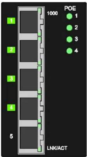
Figure 7: Port LEDs
Table 10: Legend for Figure "Port LEDs"
| LED | Name | Status | Description |
| 1000 | 10/100/1000BASE T-Ports-LED(1 LED for each port) | Green | Port in operation at 1000 Mbit/s. |
| OFF | Connection in operation at less than 1000 Mbit/s. | ||
| LNK/ACT | LNK/ACT-LED(1 LED for each port) | Green | Lights when ports are connected. |
| Flashing | Data traffic being routed over the port. | ||
| OFF | No proper link established at the port. | ||
| POE | Power over Ethernet(1 LED for each port) | Green | PoE power is on. |
| OFF | There is no PoE power. |
4.4 Label
4.4.1 Hardware and Software Version
There is a label with the serial no "S/N" on the back of the industrial switch.

Figure 8: Label (Example)
Table 11: Legend for Figure "Label (Example)"
| No. | “SN” Description |
| 02 | Firmware version (left number sequence) |
| 01 | Hardware version (right number sequence) |
4.5 Technical Data
4.5.1 Device Data
Table 12: Technical Data - Device Data
| Width | Carrier rail mounting | 50 mm |
| Height | Carrier rail mounting | 120 mm (from the top edge of the carrier rail) |
| Length | Carrier rail mounting | 160 mm |
| Weight | 800 g | |
| Degree of protection | IP30 | |
4.5.2 System Data
Table 13: Technical Data – System Data
| MAC table | Up 8000 Addresses |
| VLAN | Port based and tag based (4094 VIDs) |
| Jumbo Frame Size | 10 kB |
| Maximum length | 10/100/1000BASE-T: 100 m;RS-232: 15 m |
4.5.3 Power Supply
Table 14: Technical Data – Power Supply
| Supply voltage | 24 ... 57 VDC |
| Power consumption, max. | 13 W; 133 W with 4 PoE |
4.5.4 Communication
Table 15: Technical Data - Communication
| Ports | 4 x 10/100/1000BASE-T with PoE1 x 10/100/1000BASE-T |
| Standards | IEEE 802.3 10BASE-TIEEE 802.3u 100BASE-TXIEEE 802.3ab 1000BASE-TIEEE 802.3x Flow ControlIEEE 802.1p PrioritizationIEEE 802.3af Power over Ethernet (PoE)IEEE 802.3at High Power over Ethernet (PoE+) |
| Topology | Star |
4.5.5 Environmental Conditions
Table 16: Technical Data - Environmental Conditions
| Surrounding air temperature (operation) | -10 ... +60 °C (valid for UL 61010)-40 ... +70 °C (valid for CE) |
| Surrounding air temperature (storage) | -40 ... +80 °C |
| UL 61010 Use Pollution degree | Indoor2 |
| Relative humidity (without condensation) | 5 ... 95 % |
| Vibration resistance | Acc. to IEC 60068-2-6 |
| Shock resistance | Acc. to IEC 60068-2-27 |
| EMC-1 immunity to interference | Acc. to EN 61000-6-2 |
| EMC-1 Emission of interference | Acc. to EN 61000-6-4 |
4.6 Approvals
The following approvals have been granted for the WAGO ETHERNET accessory product “Industrial Eco Switch” (852-1411):

Conformity Marking

Ordinary Locations
UL61010-2-201 (E175199)
Table 17: Assignment UL – Hardware Version
| Approval | Hardware Version |
| UL | valid from version 03 |
5 Mounting
5.1 Installation site
The location selected to install the industrial ECO switch may greatly affect its performance. When selecting a site, we recommend considering the following rules:
- Install the industrial ECO switch at an appropriate place. See section "Device Description" > ... > "Technical Data" for the acceptable temperature and humidity operating ranges.
Make sure that the heat output from the industrial ECO switch and ventilation around it is adequate. Do not place any objects on the industrial ECO switch.
5.2 Installation on a DIN Rail
The industrial ECO switch must be grounded through the grounding screw and the DIN rail.

Note
Grounding the switch
Grounding the Industrial ECO switch prevents electromagnetic interference due to electromagnetic interference. Please refer to the corresponding standards for EMC-compliant installations.
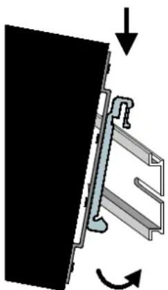
Place the industrial ECO switch onto the DIN rail from the top and snap it into position.
natural_image
Diagram of a mechanical assembly with directional arrows indicating motion (no text or symbols)Figure 9: Snapping onto the DIN Rail
5.3 Removal from DIN Rail
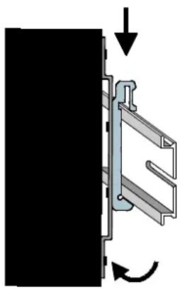
To remove the device from the DIN rail, press down on the industrial ECO switch and pull it out of the DIN rail.
natural_image
Diagram of a mechanical assembly with directional arrows indicating motion (no text or symbols)Figure 10: Removing the Device from the DIN Rail
6 Connect Devices
6.1 Power Supply
The switch uses direct-current power supply for 24 ... 57 V.
The primary network link is established via a 2-pin plug-in connection located on the top of the switch.
The female connector (order-no. 2231-102/026-000) is composed of two connecting terminals and can be inserted and removed easily by hand to connect to the 2-pin plug connector located on the top of the switch.
The power supply for the switch automatically adjusts to the local power source and can also be switched on if no or not all patch cables are connected.
- Connect a suitable grounding conductor to the grounding lug on the top of the switch.

Note
Ground for the switch
The ground for the switch prevents electromagnetic interference from electromagnetic radiation.
Observe the corresponding standards for EMC-compatible installations as well.
NOTICE
Grounding instruction!
Connect PWR - or PWR + not conductive to the earth potential.
- Plug the female connector into the male connector of the switch if it has not already been plugged in. Check the tight fit of the multipoint connector by gently shaking it.
- PWR +/-:
To connect or disconnect the conductors, actuate the spring directly in the female connector using a screwdriver or an operating tool and insert or remove the conductor. - Check whether the power LED "PWR" on the top of the device lights up when power is supplied to the device. If not, check to ensure that the power cable is plugged in correctly and fits securely.
7 Appendix
7.1 RJ-45 Cable
Always use category 5e cables to connect your network devices. The pin assignment is given below:
Table 18: RJ-45 Cable
| Contact | Description | Pair | Color (acc. EIA/TIA 568B) | |
| 4-wire | 8-wire | |||
| 1 | TD | D1+ | 2 | White/Orange |
| 2 | TD- | D1- | 2 | Orange |
| 3 | RX+ | D2+ | 3 | White/Green |
| 4 | Not assigned | D3+ | 1 | Blue |
| 5 | Not assigned | D3- | 1 | White/Blue |
| 6 | RX- | D2- | 3 | Green |
| 7 | Not assigned | D4+ | 4 | White/Brown |
| 8 | Not assigned | D4- | 4 | Brown |

Note
Functions on the RJ45 connector
The industrial ECO switch offers the functions autocrossing und autonegotiation to the RJ-45 connection.
7.2 PoE (Power over Ethernet) Performance Classes
PoE can be divided into different performance classes:
Table 19: PoE Performance Classes
| Performance class | Power at PSE output | Power at PD output |
| 0 | 15.4 W | 13.0 W |
| 1 | 4.0 W | 3.84 W |
| 2 | 7.0 W | 6.49 W |
| 3 | 15.4 W | 13.0 W |
| 4^* | 25.5 W | 25.5 W |
* PoE+ acc. IEEE 802.3at
The PSE (Power Sourcing Equipment) applies a defined voltage to the PD (Power Device) and measures the corresponding current (“Classification Current”). The PD is assigned to a performance class based on the current.
Table 20: PD Assignment – Performance Class
| Classification current PD | Performance class |
| 0 ... 5 mA | 0 |
| 8 ... 13 mA | 1 |
| 16 ... 21 mA | 2 |
| 25 ... 31 mA | 3 |
| 35 ... 45 mA | 4 |
| ≥ 51 mA | 0 |
List of Figures
Figure 1: Front View of the Industrial ECO Switch....20
Figure 2: Top View of the Industrial ECO Switch....21
Figure 3: Grounding screw....22
Figure 4: Power Supply (PWR) Port....23
Figure 5: Network Connections ......24
Figure 6: Device LED....26
Figure 7: Port LEDs....27
Figure 8: Label (Example)....28
Figure 9: Snapping onto the DIN Rail....32
Figure 10: Removing the Device from the DIN Rail ....33
List of Tables
Table 1: Number Notation ...... 8
Table 2: Font Conventions 8
Table 3: Comparison of PoE and PoE+....16
Table 4: Calculation Example for PoE+....16
Table 5: Legend for Figure “Front View of the Industrial ECO Switch”....20
Table 6: Legend for Figure "Top View of the Industrial ECO Switch" .....21
Table 7: Legend fort Figure "Power Supply (PWR) Port "....23
Table 8: Legend fort the Figure "Network Connections" .....24
Table 9: Legend for Figure "Device LED"....26
Table 10: Legend for Figure "Port LEDs"......27
Table 11: Legend for Figure "Label (Example)"......28
Table 12: Technical Data - Device Data ......29
Table 13: Technical Data – System Data ......29
Table 14: Technical Data – Power Supply....29
Table 15: Technical Data - Communication....29
Table 16: Technical Data - Environmental Conditions ....30
Table 17: Assignment UL – Hardware Version....31
Table 18: RJ-45 Cable 35
Table 19: PoE Performance Classes....36
Table 20: PD Assignment – Performance Class....36
- WAGO ETHERNET Accessories 852
- 852-1411
- Table of Contents
- Notes about this Documentation ....5
- Important Notes 9
- General 15
- Device Description....19
- Notes about this Documentation
- Note
- Always retain this documentation!
- Validity of this Documentation
- Copyright
- Symbols
- DANGER
- Personal Injury!
- Personal Injury Caused by Electric Current!
- WARNING
- CAUTION
- NOTICE
- Damage to Property!
- Damage to Property Caused by Electrostatic Discharge (ESD)!
- Important Note!
- Information
- Additional Information:
- Number Notation
- Font Conventions
- Important Notes
- Legal Bases
- Subject to Changes
- Personnel Qualification
- Proper Use of the Industrial Switches
- Technical Condition of Specified Devices
- Standards and Regulations for Operating the Industrial Switches
- Safety Advice (Precautions)
- Protect the components against materials having seeping and insulating properties!
- Clean only with permitted materials!
- Do not use any contact spray!
- Do not reverse the polarity of connection lines!
- Avoid electrostatic discharge!
- Special Use Conditions for ETHERNET Devices
- General
- Package Contents
- Industrial ETHERNET Technology
- Switching Technology
- PoE (Power over Ethernet)
- Calculation example for PoE+:
- Operating Mode A
- Operating Mode B
- Autonegotiation
- Autocrossing
- Store-and-forward switching mode
- Transmission Methods
- Device Description
- View
- Front View
- Top View
- Connectors
- Grounding screw
- Grounding instruction!
- Power Supply (PWR/RPS)
- Network Connections
- Capping unused ports!
- 10/100/1000BASE-T ports with PoE+
- 10/100/1000Base-T ports
- Display Elements
- Device LED
- Port LEDs
- Label
- Hardware and Software Version
- Technical Data
- Device Data
- System Data
- Power Supply
- Communication
- Environmental Conditions
- Approvals
- Mounting
- Installation site
- Installation on a DIN Rail
- Grounding the switch
- Removal from DIN Rail
- Connect Devices
- Power Supply
- Ground for the switch
- Appendix
- RJ-45 Cable
- Functions on the RJ45 connector
- PoE (Power over Ethernet) Performance Classes
- List of Figures
- List of Tables
Brand : Wago
Model : 852-1411
Category : Switch