
RPK4-HD1101 - Car kit PAC - Free user manual and instructions
Find the device manual for free RPK4-HD1101 PAC in PDF.


| Product Type | Radio Replacement Kit with Climate Control Retention |
| Compatible Vehicles | 2003-2007 Honda Accord |
| HVAC System Compatibility | Single Zone and Dual Zone (with selectable inserts) |
| Steering Wheel Control Retention | Yes, programmable with short press/long press dual command |
| Radio Brand Compatibility | Alpine, JVC, Kenwood, Clarion, Pioneer, Sony, Fusion, and others |
| Included Components | Dash kit, HVAC control panel, radio mounting brackets, pocket, interface module, harnesses, USB extension (USBDMA3), HVAC knob inserts, duct sealing foam |
| Display Type | LCD on HVAC control panel |
| Power Input | 12V DC from vehicle (battery/accessory) |
| Dimensions (Dash Kit) | Standard double DIN opening (approx. 7 x 4 inches) |
| Weight | Approximately 2.5 lbs (1.13 kg) |
| Driving Position Support | Left-hand drive and right-hand drive (programmable) |
| Data Outputs | Vehicle speed sensor (VSS), reverse trigger, parking brake |
| Programming Menu Options | SWC programming, HVAC type, SWC re-calibration, temperature unit, driver position, knob swap, reset |
| Firmware Update | Via RadioPRO app (requires interface) |
| Warranty | 1 year limited (typical PAC warranty) |
Frequently Asked Questions - RPK4-HD1101 PAC
User questions about RPK4-HD1101 PAC
0 question about this device. Answer the ones you know or ask your own.
Ask a new question about this device
Download the instructions for your Car kit in PDF format for free! Find your manual RPK4-HD1101 - PAC and take your electronic device back in hand. On this page are published all the documents necessary for the use of your device. RPK4-HD1101 by PAC.
USER MANUAL RPK4-HD1101 PAC
The RPK4-HD1101 is a complete radio replacement kit with integrated climate control retention for the 2003-2007 Honda Accord. This kit utilizes a user friendly pair of HVAC control knobs for a more factory look and experience. Using the supplied interchangeable inserts, this kit is compatible with both single zone or dual zone HVAC systems. This kit is also programmable for use in both left hand drive and right hand drive vehicles. The included radio replacement interface will retain factory steering wheel controls (SWC) and allows you to program two radio functions to each SWC button by using short press long press dual command functionality. The interface also provides data bus driven outputs such as vehicle speed sensor (VSS), reverse trigger and parking brake.
Table of Contents: Page:
1. Factory Radio Removal 1-2
2. Sub-Dash Preparation Sealing the Air Ducts----3
3. Radio Replacement Installation and Wiring Instructions---- 3-4
4. Kit Assembly Instructions 5-6
5. Settings Menu (including SWC programming)---- 7-9
Parts List
The RPK4-HD1101 includes everything you need for a professional installation of an aftermarket radio in your Accord.
This kit contains:
- Dash Kit
a.1 (x1) HVAC Control Panel
b.1 (x2) Radio Mounting Brackets (One left and one right)
c.1 (x1) Pocket (For single DIN applications)
d.1 (x8) Radio Mounting Screws
- Lower Pocket
- Climate and Steering Wheel Control Interface Module
- Adapter for Vehicles Equipped with the Factory Navigation Radio
- HVAC Knob Inserts
- Radio Connection Harnesses
- 1 Sheet of HVAC Duct Sealing Material. (Used when the factory foam has deteriorated between the ducts behind the radio.)
- USBDMA3 - USB extension for use with the aftermarket radio

natural_image
Black automotive dashboard box with labeled parts (no readable text or symbols)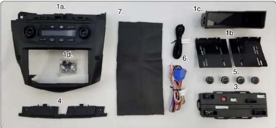
Important Notes
***Please check all functions of the factory steering wheel controls and HVAC system and make sure it is all in good working order before proceeding with this install.***
- This version of instructions are ONLY intended for use with product version R.2.1.2.8 or later.
- The Pink / Black data input wire only needs to be connected in vehicles equipped with single zone climate controls. See page 6 to identify the HVAC system in the vehicle.
- The White / Black navigation SWC input wire only needs to be connected in vehicles equipped with the factory navigation radio, and when the supporting "Voice" and "Back" steering wheel controls are present.
- The HVAC control panel will need to be programmed to the factory HVAC system in the vehicle. Upon powering the panel up for the first time it will enter this programming mode. Please see page 6 for proper selection.
- A pocket has been provided to replace the factory pocket below the radio. The pocket comes with a cut out sized specifically for use with the included PAC USBDMA3.
Part One: Removing the factory radio from the vehicle
1.1 - Push the hazard warning switch button (A). Carefully insert a flat-tip screwdriver into the slot below the button, and push down on the center clip.

1.2 - Pull the upper panel (A) in the direction shown to release the remaining clips, disconnect the hazard warning switch connector (B), and if equipped, sunlight sensor connector (C) and navigation sub display connector (D). Detach the harness clips (E), then remove the upper panel.

1.3 - If the vehicle is equipped with manual transmission, the shift knob (A) will need to be removed. To do this, lower the shift lever boot (B) to release the hooks (C) from the knob. Remove the shift knob by twisting it counterclockwise.

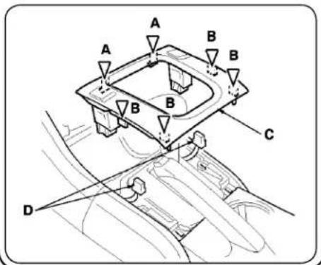
1.4 - Using a plastic trim tool, detach the clips (A, B) by pulling the center console front panel (C) up. If equipped, disconnect the seat heater switch connectors (D).
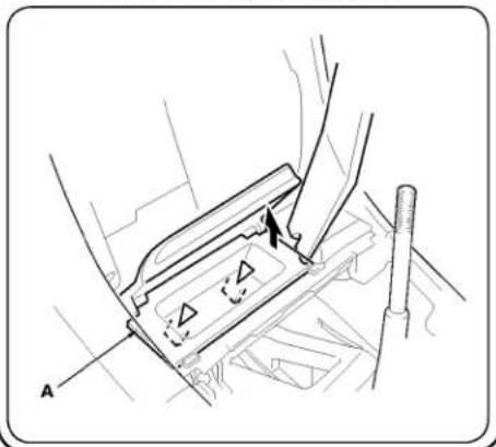
1.5 - Using a plastic trim tool, pry up on the right side of the console pocket (A) with a trim tool, and detach the clips, then remove the pocket.
natural_image
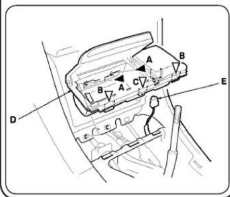
Technical diagram of a mechanical assembly with no visible text or symbols1.6 - Remove the screws (A), detach the clips (B) and hook (C) by pulling the center holder (D) up, and disconnect the front accessory power socket connector (E).
1.7 - Remove the center pocket (A). To do this, remove the screws (B). Open the lid, then pull the pocket toward you by hand to detach the clips (C). Close the lid, then remove the pocket.

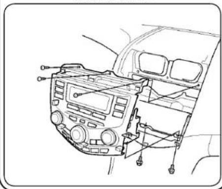
1.8 - Remove the 3 phillips head screws and 2 8mm bolts holding the radio to the dash. Pull the radio from the dash and disconnect the connectors and the antenna lead, then remove the radio and set aside.
natural_image
Line drawing of a car dashboard with control panel and buttons (no text or symbols)Part Two: Sub-Dash Preparation
The sub-dash of the vehicle will need to be modified to fit the new aftermarket radio. Please see below for proper modification of the sub-dash. Be sure to leave the left and right lower clip mount intact as they will be re-used by the new dash kit.
- Cut and remove the portion of the dash that is outlined below. Be sure to cut close to the left and right square mounting holes but be sure they are left intact.

natural_image
Close-up of a white plastic car front panel with blue adhesive tape, no visible text or symbols- The Sub-dash should look like the image below when the removal is complete. Notice that the left and right square mounting holes are still left intact.

natural_image
Close-up of car engine components with blue connectors and wiring (no visible text or symbols)Blocking the Air from the Air Ducts Behind the Radio
In vehicles equipped with dual zone climate controls, leaking air ducts will cause false readings to the temperature sensors in the dash kit. This will cause the Auto climate feature to not heat or cool the cabin to the proper temperature. It is common for the ducts behind the radio to leak due to deterioration of the seals between the main and center ducts. To help block the air from blowing on the back of the temperature sensors we have added a piece of closed cell foam, measuring 6" x 12".
- Connect the factory radio and turn the HVAC fan speed to high.
- Verify if and where there is an air leak. The picture on the right shows the common leak locations.
- Using the closed cell foam provided as-is, or cut adequate pieces to block the air from blowing on the back of the Temp sensors located just outside of the radio opening on each side of the dash kit.
- Verify that all of the air leaks have been sealed or redirected away from the temperature sensors.
- Disconnect the radio and proceed to the next step.

natural_image
Interior view of a car body panel with white arrows pointing to structural elements (no text or symbols visible)Part Three: Configuration and Wiring of Interface
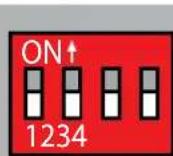
Set DIP switches that match your radio to the ON position
Set all other DIP switches to the OFF position
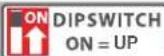
| Alpine JV | Kenwood Clarion Pioneer | Other Sony Fusion | |||
| 1 | 2 | 1 & 2 | 3 | 1, 2, & 3 | 4 |
Other = Advent, BOYO, Dual, Lightning Audio, Rockford Fosgate, Visteon
-
The radio select DIP switches on the front of the interface must be adjusted to the proper radio setting before plugging the interface into the vehicle.
-
Make all connections between the aftermarket radio and the RPK4-HD1101 harness as described in the chart on the next page. This includes the SWC 3.5mm jack or the SWC wire (aftermarket radio MUST support a wired remote input).
- Connect the Pink / Black data wire when the vehicle is equipped with single zone HVAC controls, and data generated navigation outputs are needed. See the next page for connection details.
- Connect the White / Black navigation SWC wire when the vehicle is equipped with the factory navigation system, and when the supporting "Voice" and "Back" steering wheel controls are present. See the next page for connection details.
- Connect one side of the harness labeled "RPK-HD1101-16P" to the back of the kit. Connect the other end of the harness to the radio replacement interface.
- Connect the single zone HVAC harness or dual zone HVAC harnesses to the radio replacement interface. For proper operation confirm that the connectors are connected into the proper openings. Failure to verify will cause the HVAC kit to function incorrectly. Reference the illustration on the next page or the sticker on the back of the module for clarification. If the vehicle is equipped with factory navigation then connect the OEM upper display harness as well.
- If you wish to reassign functions to the SWC follow the programming instructions on page 7.
Aftermarket Radio Connections
| Yellow | Battery +12v |
| Black | Ground |
| Red | Accessory Output |
| White | Front Left + input |
| White / Black | Front Left - input |
| Grey | Front Right + input |
| Grey / Black | Front Right - input |
| Green | Rear Left + input |
| Green / Black | Rear Left - input |
| Purple | Rear Right + input |
| Purple / Black | Rear Right - input |
| Blue | Amp Remote Turn On |
| Light Green | Parking Brake |
| Pink | Vehicle Speed Output |
| Orange | Illumination Output (+) |
| Purple / White | Reverse Output (+) |
| White / Black* | Navigation SWC Input |
| Pink / Black* | Data Input |
| Blue / Yellow (SWC Output) | Kenwood or Newer JVC |
| 3.5mm Jack (SWC) Output | Alpine, JVC, Clarion, Pioneer, Sony, Boyo, Dual, Lightning Audio, Visteon, Jensen or Advent |
* This wire is longer than the others and will need to be run to the kick panel area. See below for more information.
Connecting the Pink / Black wire
Note: This wire is only needed when the vehicle is equipped with single zone HVAC controls. See page 5 if you are unclear as to which HVAC system is in your vehicle.
Route the Pink / Black wire from the RPK4-HD1101's vehicle harness down to the driver side kick panel. Connect the Pink / Black wire to the Brown / Yellow wire located in the 45-pin white connector located above the fuse panel. It will be necessary to remove the under dash panel if equipped.

natural_image
Close-up of a white electrical connector with multicolored wires and a red arrow pointing to a component (no text or symbols visible)Connecting the White / Black wire
Note: This wire is only needed when the vehicle is equipped with the factory navigation system and when the supporting "Voice" and "Back" steering wheel controls are present.
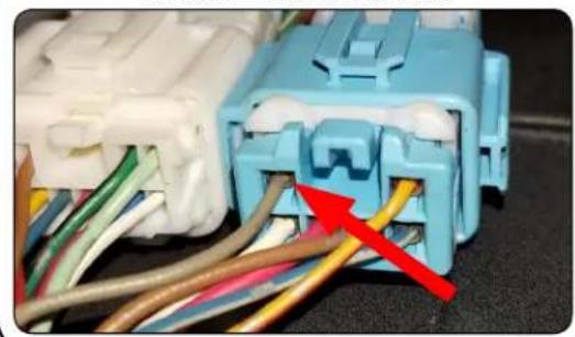
Route the White / Black wire from the RPK4-HD1101's vehicle harness down to the passenger side kick panel. Connect the White / Black wire to the Gray wire located in the 6-pin blue connector. Disconnect the 14-pin green connector from the navigation module located in the trunk area.
natural_image
Close-up of a blue automotive connector with visible wiring and colored wires, no text or symbols present.Illustration / Schematic

Note: For proper operation confirm that the connectors are connected into the proper openings. Failure to verify will cause the HVAC kit to function incorrectly. Reference the sticker on the back of the module for clarification.
Part Four: Kit Assembly Instructions
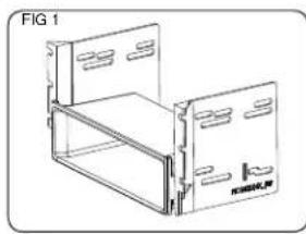
- When using a single DIN radio, snap and lock each of the side brackets onto the supplied pocket. FIG 1
- When using a double DIN radio, remove the shaded tabs from the back edge of each left and right mounting brackets (right side not shown). FIG 2
- Push the 4 supplied spring clips onto the 4 tabs on the back of the HONK824X dash kit. FIG 3
- Using the supplied phillips head screws, line up and secure the side radio mounting brackets to the main frame of the HONK824X dash kit. FIG 4
- Insert ISO mountable radio between the side mount brackets and loosely attach to sides of radio using the screws provided with the radio when possible, or hardware included with the kit.
- Move the radio's chassis forward or backward for desired look and insert and tighten screws.
- If the vehicle was equipped with a factory radio with navigation you will need to install the navigation spacer to the top of the kit. Using 2 of the supplied screws fasten the spacer to the top of the kit. (FIG 5) You will also need to remove the shaded area from the center clip mount using a rotary or similar tool. (FIG 6)
- When using a single DIN radio, attach a rear support bracket to the rear of the new radio. Adjust as necessary to attach to the rear support stud, located on the back of the pocket using the small phillips screw supplied with kit (optional).
- Insert the kit and radio combo into the dash. Line up the mounting tabs with the factory mounting points. Lock the kit into the dash by applying pressure to the face of the kit and pushing it into the dash. Secure the kit to the sub-dash using the 3 phillips head screws removed in step 1.8 on page 2.
natural_image
Technical line drawing of a two-tiered storage unit (no text or symbols)
natural_image
Technical line drawings of two electronic device modules, one with a central component and the other with a bracket (no text or symbols)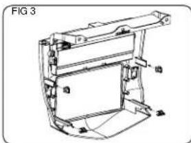
natural_image
Technical line drawing of a mechanical component with no visible text or symbols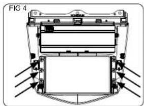
natural_image
Technical diagram of a mechanical assembly with directional arrows indicating flow or movement (no text or symbols)
natural_image
Technical diagram of a mechanical assembly with layered components and mounting holes (no text or symbols)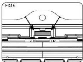
natural_image
Technical line drawing of a mechanical assembly (no text or symbols)Pocket and Vehicle Assembly
Due to the position of the chassis of the aftermarket radio after installation, the cover for the factory pocket will not open and close without hitting it. We have added a finish matched replacement pocket to this kit. The replacement pocket will require use of the fasteners from the factory pocket.
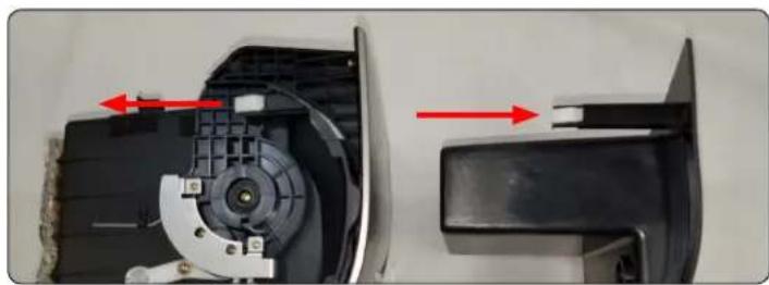
- Start by removing the 2 white clips at the top of the factory pocket removed in step 1.7. Clip them into the same locations on the new pocket. See FIG 7 below for reference. Only one side is shown in the picture, but both sides will need to be done.
- Next remove the 2 silver screw clips at the bottom of the factory pocket. Clip them into the same locations on the new pocket. See FIG 8 below for reference.
FIG 7
natural_image
Close-up of a mechanical device showing internal components and red directional arrows indicating movement (no text or symbols visible)FIG 8

natural_image
Close-up of two car dashboard control buttons with red arrows pointing to each (no text or symbols visible)- Install the pocket into the dash by sliding it back until the clips lock into the openings in the dash. Secure it using the two philips head screws removed in step 1.7.
- Connect the front accessory power socket connector, and seat the center holder back into the dash. Secure it using the two phillips head screws removed in step 1.6.
- Snap the console pocket removed in step 1.5 back into the center holder by pressing it down and forward.
- Install the center console front panel removed in step 1.3 and 1.4 making sure to plug the seat heater connectors back in (if equipped).
- Install upper panel in reverse order as removed in steps 1.1 and 1.2 making sure to plug in the hazard switch and the navigation sub display (if equipped).
Identifying the HVAC system in your vehicle

Single Zone

Dual Zone Dual Zone

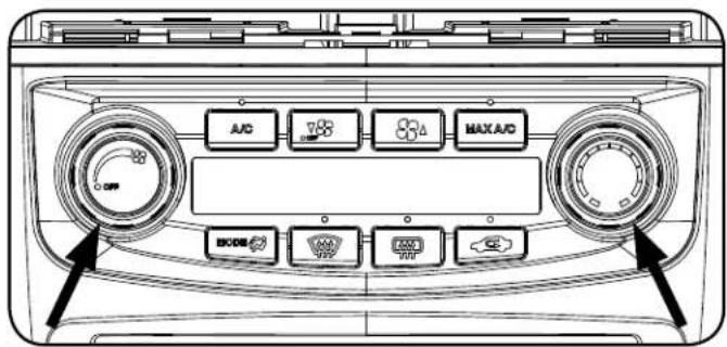
Once you have identified the HVAC system in your vehicle using the images above, insert the correct knob inserts into the front of the knob opening and verify that they click into place. To avoid damage to the kit or the inserts make sure that the inserts are positioned correctly and very little force should be used when seating them.
Single Zone

Dual Zone
HVAC System Setup
Initial HVAC type selection.
- When the ignition is turned to the on position and the kit is powered up in the vehicle for the first time "P2 should be shown on the display.
-
This tells you that you are in programming menu 2 along with the current selection on the right of the display which in this case is 1. The available selections are as follows:
-
Coupe (2 Door) with Dual Zone Climate Controls
- Sedan (4 Door) with Dual Zone Climate Controls
- Coupe (2 Door) with Single Zone Climate Controls
-
Sedan (4 Door) with Single Zone Climate Controls
-
Using the Fan Up and Fan Down buttons change the current selection to match the factory system in the vehicle.
- Once the desired selection is shown, press the rear defrost button (next to the button) to save and exit.
Part 5: RPK4-HD1101 Settings Menu
The following settings can be adjusted using the LCD and controls of the dash kit even after the install of the dash kit has been completed. Each of the processes are described below, along with the combination of buttons needed to adjust the setting. The settings available for adjustment are as follows:
P1. Programming of the Steering Wheel Controls
P2. HVAC Type
- Coupe (2 Door) with Dual Zone Climate Controls
- Sedan (4 Door) with Dual Zone Climate Controls
- Coupe (2 Door) with Single Zone Climate Controls
- Sedan (4 Door) with Single Zone Climate Controls
P3. Steering Wheel Control Re-calibration
P4. Temperature Unit
- Fahrenheit (Default)
- Celsius
P5. Driver Position
- Left Hand Drive (Default)
- Right Hand Drive
P6. Temperature Rotary Knob Position
- Left Hand Drive (Default)
- Right Hand Drive
P7. Reset
- Exit (Default)
- Reset
P1. - Programming Steering Wheel Controls
IMPORTANT! The interface comes pre-programmed for the functions listed in the chart below and does not require programming unless you wish to re-assign the SWC functions, or utilize short press long press dual command functionality. The SWC can always be restored to default settings by entering the Steering Wheel Control programming menu (see page 8) and waiting 7 seconds for the interface to time out.
Default SWC Button Assignments
| Alpine JVC Kenwood Clarion Pioneer Sony Fusion | |||||||
| Volume + | Volume + Volume + Volume + Volume + Volume + Volume + Volume + Volume + Volume - | ||||||
| Volume - | Volume - Volume - Volume - Volume - Volume - Volume - Volume - Volume - Volume - Volume - Volume - Volume - Volume - Volume - Volume - Volume - Volume - Volume - Volume - Volume - Volume - Volume - Volume - Volume - Volume - Volume - Volume - Volume - Volume - Volume - Volume - Volume - Volume - Volume - Volume - Volume - Volume - Volume - Volume - Volume - Volume - Volume - Volume - Volume - Volume - Volume - Volume - Volume - Volume - Volume - Volume - V | ||||||
| Track Up | Track + | Track + | Track + | Search + | Track + | Track + | Track + |
| Track Down | Track - | Track - | Track - | Search - | Track - | Track - | Track - |
| Mode | Source | Source | Source | Source | Source | Source | Source |
| Voice | Voice | Mute | Mute | VR | VR | VR | Power |
| Back | Preset | Preset | Disc - | End | Preset | Reject | N/P |
Optional Steering Wheel Control Programming
If you wish to re-assign the SWC functions or utilize short press long press dual command functionality, the interface must be programmed in the specific order shown in the chart on the next page. If you come across a function in the chart that your steering wheel does not have, or you do not want to program, press and release the rear defrost [icon] button to skip that function. The LED will flash off and on confirming that you have successfully skipped that function and are ready to proceed to the next one.
Short Press Long Press Dual Command Functionality
This feature allows you to assign two aftermarket radio functions to each of the vehicle's SWC buttons. It can be used with as many of the buttons as the user likes or none at all. When this functionality is implemented, quickly pressing and releasing a SWC button will initiate the short press command, while pressing and holding a SWC button for longer than two seconds will initiate the long press command. If you wish to assign dual command functionality to the SWC please follow the programming steps on the next page.
RPK4-HD1101 Settings Menu (cont.)
Optional Programming Order
| Alpine JVC | Denwood Clarion | Other ■ | Pioneer Sony | Fusion | ||||
| 1 Volume - | Volume + Volume - | Volume + Volume + | Volume + Volume + | Volume + | ||||
| 2 Volume - | Volume - Volume - | Volume - Volume - | Volume - Volume - | Volume - | ||||
| 3 | Mute | Mute | Mute | Mute | Mute | Mute | Mute | Mute |
| 4 | Preset + | Source | Source | Source | Preset + | Preset + | Preset + | Source |
| 5 | Preset - | Track + | Play | Search + | Preset - | Preset - | Preset - | Track + |
| 6 | Source | Track - | Track + | Search - | Source | Source | Source | Track - |
| 7 | Track + | Band / Disc + | Track - | Band | Track + | Track + | Track + | Audio |
| 8 | Track - | Preset / Disc - | Disc / FM + | Send / End | Track - | Track - | Track - | Power |
| 9 | Power | Select | Disc / AM - | Send | Band | Band | Band | |
| 10 Enter/Play | Attenuation Answer End | Answer ☐ | Phone Menu | Reject Call / Source (Bluetooth equipped radios only) | ||||
| 11 | Band / Program | Phone Receive | Voice Dial | VR | End ☐ | Answer Call | Answer / End Call | |
| 12 Receive | Phone Reject | On Hook | PTT ☐ | End Call | VR | |||
| 13 | End | Voice Dial Off Hook | VR | |||||
| 14 | VR | Power | Mute (Multimedia units only) | |||||
| 15 | Preset + | |||||||
| ☐ - Advent, Boyo, Dual, Lightning Audio, Jensen, Rockford Foggate & Visteon ☐ - Jensen & Advent ONLY | ||||||||
Programming Sequence
- Start with the Ignition in the OFF position.
- Press and hold the Dual (dual zone) or Fan Speed (single zone) button.
- While holding the button down turn the key to the ignition position and continue to hold for 7 seconds or until "P1" is shown on the display.
- At this point the MAX A/C Green LED will turn on solid.
- Within 7 seconds, press the button that is to be learned on the steering wheel. The MAX A/C green LED will turn off when the button is pressed.
At this point you have two options:
A. For short press functionality: Release the button within 1.5 seconds. The MAX A/C green LED will turn back on.
B. For long press functionality: Hold the button until the MAX A/C green LED starts blinking. Release the button and the MAX A/C Green LED will go back to solid.
- If you need to program more buttons, repeat step 5 for each additional audio function on the steering wheel.
- If you come across a function in the chart that your steering wheel does not have, or you do not want to program, press and release the Mode button to skip that function. The MAX A/C green LED will flash off and on confirming that you have successfully skipped that function.
- Once programming is completed, wait seven seconds. The MAX A/C green LED will flash three times indicating end of programming.
- Test the interface for proper functionality. If any function does not work, repeat the programming steps.
P2. - HVAC type selection.
- Start with the Ignition in the OFF position.
- Press and hold the MODE button.
- While holding the button down turn the key to the ignition position and continue to hold for 7 seconds or until "P2" is shown on the display.
-
This tells you that you are in programming menu 2 along with the current selection on the right of the display which will be between 1 and 4. The available selections are as follows:
-
Coupe (2 Door) with Dual Zone Climate Controls
- Sedan (4 Door) with Dual Zone Climate Controls
- Coupe (2 Door) with Single Zone Climate Controls
-
Sedan (4 Door) with Single Zone Climate Controls
-
Using the Fan Up and Fan Down buttons change the current selection to match the factory system in the vehicle.
- Once the desired selection is shown, press the rear defrost button (next to the button) to save and exit.
P3. - Steering Wheel Control Re-calibration.
SWC re-calibration is necessary when the SWC operation is erratic or non-existent. This process re-calibrates the SWC values to the RPK4 interface so it will know what they can be set to for button function assignment. The interface must be programmed in the specific order shown in the table below. If your vehicle is not equipped with the Voice and Back navigation buttons you will end programming by waiting 7 seconds for the module to time out after the Mode button has been programmed. The SWC and radio command assignments can always be restored to default values by entering re-calibration mode (Steps 1-3) and not pressing any buttons. After 7 seconds the re-calibration mode will time out and all default values will be restored.
- Start with the Ignition in the OFF position.
- Press and hold the Auto ☑ or Temp Ⓞ button.
- While holding the button down turn the key to the ignition position and continue to hold for 7 seconds or until "P3" is shown on the display. At this point the recirculation amber LED will turn on solid.
- Within 7 seconds, press the button that is to be learned on the steering wheel. The recirculation amber LED will turn off when the button is pressed. Once the value has been successfully learned the LED will start flashing. Release the button after the 3rd flash.
- If you need to program more buttons, repeat step 4 for each additional audio function on the steering wheel.
- Once programming is completed, wait seven seconds. The recirculation amber LED will flash three times indicating end of programming.
- Test the interface for proper functionality. If any function does not work, repeat the programming steps.
- After you have re-calibrated the SWC buttons, the default SWC button assignments will be the same as what is listed in the chart on page 7. If you wish to re-assign button functions you must also go through the programming process (P1) on the previous page.
| Button Programming Order |
| Volume Up |
| Volume Down |
| Track Up |
| Track Down |
| Mode |
| Voice |
| Back |
RPK4-HD1101 Settings Menu (cont.)
P4. - Temperature unit selection.
- Start with the Ignition in the OFF position.
- Press and hold the MAX A/C button.
- While holding the button down turn the key to the ignition position and continue to hold for 7 seconds or until "P4" is shown on the display.
-
This tells you that you are in programming menu 4 along with the current selection on the right of the display which is 1 by default. The available selections are as follows:
-
Fahrenheit (Default)
-
Celsius
-
Using the Fan Up and Fan Down buttons change the current selection to match the desired temperature units.
-
Once the desired selection is shown, press the rear defrost button 📄 (next to the 📄 button) to save and exit.
\*\*\*This Section is for Right Hand Drive Dual Zone vehicles only\*\*\*
P5. - Driver Position Selection
This selection needs to be set to right hand drive as it lets the kit know which side of the vehicle the driver is on. This also changes which of the temperature knobs has priority. Since the driver side knob should always have priority, we adjust the priority based on your selection.
- Start with the Ignition in the OFF position.
- Press and hold the A/C button.
- While holding the button down turn the key to the ignition position and continue to hold for 7 seconds or until "P5" is shown on the display.
-
This tells you that you are in programming menu 5 along with the current selection on the right of the display which is 1 by default. The available selections are as follows:
-
Left Hand Drive (Default)
-
Right Hand Drive
-
Using the Fan Up and Fan Down buttons change the current selection to match the proper driving position..
- Once the desired selection is shown, press the rear defrost button (next to the button) to save and exit.
P6. - Temperature Rotary Knob Position Swap
In right hand drive vehicles, this selection also needs to be set to right hand drive. This will make sure that the temperature knob on the right of the kit controls the right side of the vehicle and the left temperature knob will control the left side. In the event that you select right hand drive in this menu and the rotary knobs are inverted please change the setting to left hand drive, even if the vehicle is a right hand drive.
- Start with the Ignition in the OFF position.
- Press and hold the Recirculation button.
- While holding the button down turn the key to the ignition position and continue to hold for 7 seconds or until "P6" is shown on the display.
-
This tells you that you are in programming menu 6 along with the current selection on the right of the display which is 1 by default. The available selections are as follows:
-
Left Hand Drive (Default)
-
Right Hand Drive
-
Using the Fan Up and Fan Down buttons change the current selection to match the proper driving position.
- Once the desired selection is shown, press the rear defrost button (next to the button) to save and exit.
P7. - Reset
This selection allows the user to reset the HVAC portion of the kit and return it to the initial HVAC type selection found at the bottom of page 6.
- Start with the Ignition in the OFF position.
- Press and hold the MAX A/C MAXA/D and Auto or Temp button at the same time.
- While holding these buttons down, turn the key to the ignition position and continue to hold for 7 seconds or until "P7" is shown on the display.
-
This tells you that you are in programming menu 7 along with the current selection on the right of the display which is 1 by default. The available selections are as follows:
-
Exit (without resetting)
-
Reset
-
Using the Fan Up and Fan Down buttons change the current selection to match the desired temperature units.
- Once the desired selection is shown, press the rear defrost button (next to the button) to select and exit.
RPK4-HD1101 Testing and Verification
- Turn the ignition to the on position.
- Turn on the radio and check balance, fade and that all steering wheel controls are functioning properly.
- Verify that all of the HVAC controls are functioning properly.
Troubleshooting
- Steering wheel controls work intermittently. This is typically caused by the original Honda "clock spring" aging. - Install the included .47uF non polarized capacitor between the steering wheel control wire (White) and the steering wheel return wire (Black). For more information on installing this capacitor, there is a tech brief located in the download section of the RPK4-HD1101 product page on the PAC website (PAC-audio.com).
Technical Support and Product Updates (Firmware)
The RadioPRO app will also allow you to update the interface with new firmware as it becomes available. Please visit PAC-audio.com or contact our tech support department to see if there is a firmware update for your interface.
Technical Support
support@PAC-audio.com
866-931-8021



- Parts List
- This kit contains:
- Important Notes
- Part One: Removing the factory radio from the vehicle
- Part Two: Sub-Dash Preparation
- Blocking the Air from the Air Ducts Behind the Radio
- Part Three: Configuration and Wiring of Interface
- Connecting the Pink / Black wire
- Connecting the White / Black wire
- Part Four: Kit Assembly Instructions
- Pocket and Vehicle Assembly
- Identifying the HVAC system in your vehicle
- HVAC System Setup
- Initial HVAC type selection.
- Part 5: RPK4-HD1101 Settings Menu
- P1. Programming of the Steering Wheel Controls
- P2. HVAC Type
- P3. Steering Wheel Control Re-calibration
- P4. Temperature Unit
- P5. Driver Position
- P6. Temperature Rotary Knob Position
- P7. Reset
- P1. - Programming Steering Wheel Controls
- Optional Steering Wheel Control Programming
- Short Press Long Press Dual Command Functionality
- RPK4-HD1101 Settings Menu (cont.)
- Optional Programming Order
- Programming Sequence
- At this point you have two options:
- P2. - HVAC type selection.
- P3. - Steering Wheel Control Re-calibration.
- P4. - Temperature unit selection.
- \*\*\*This Section is for Right Hand Drive Dual Zone vehicles only\*\*\*
- P5. - Driver Position Selection
- P6. - Temperature Rotary Knob Position Swap
- P7. - Reset
- RPK4-HD1101 Testing and Verification
- Troubleshooting
- Technical Support and Product Updates (Firmware)
Brand : PAC
Model : RPK4-HD1101
Category : Car kit