
DSM48 - Loudspeaker Citronic - Free user manual and instructions
Find the device manual for free DSM48 Citronic in PDF.


| Product Type | Digital Speaker Management System |
| Channels | 4 inputs, 8 outputs (balanced XLR) |
| Input Type | Analogue or AES digital (XLR) |
| DSP Processor | 96kHz, 32-bit floating point |
| Input EQ | 8-band parametric EQ per input |
| Output EQ | 8-band parametric/shelf EQ per output |
| Crossover Filters | HPF + LPF per output; Linkwitz-Riley, Bessel, Butterworth; slopes 12/18/24/48 dB/oct |
| Delay | 0 to 1000 ms (per input/output) |
| Compressor/Limiter | 6 independent output compressor/limiters (adjustable threshold, attack, release, ratio) |
| Noise Gate | Per input; threshold -120 to +10 dBu |
| Gain Range (Input) | -40 to +6 dB (0.1 dB steps) |
| Gain Range (Output) | -40 to +15 dBu |
| Frequency Response | 20 Hz - 20 kHz |
| Power Supply | 115/230 Vac, 50/60 Hz (IEC) |
| Power Consumption | <25 W |
| Dimensions (W x H x D) | 482 x 44 x 220 mm |
| Weight | 3.19 kg |
| Controls | Front panel rotary encoders, buttons, LCD display, USB; PC software via USB or LAN |
| Networking | Up to 250 units via LAN (RJ45) |
| Protection | Over-temperature cut-out, security lock, bypass switch |
| Included Accessories | PC software (DSP Ver 3.9), driver disc, user manual |
| Cleaning | Use a dry cloth; do not use liquids or solvents |
| Safety | Class I equipment; no user-serviceable parts; refer servicing to qualified personnel |
Frequently Asked Questions - DSM48 Citronic
User questions about DSM48 Citronic
0 question about this device. Answer the ones you know or ask your own.
Ask a new question about this device
Download the instructions for your Loudspeaker in PDF format for free! Find your manual DSM48 - Citronic and take your electronic device back in hand. On this page are published all the documents necessary for the use of your device. DSM48 by Citronic.
USER MANUAL DSM48 Citronic
Order ref: 170.668UK
User Manual


Features
• 4 inputs, 8 outputs, fully balanced
• Independent parametric EQs
- Delay and Compressor/Limiter/Gate functions
- All inputs/outputs independently controlled
- Controllable via front panel, USB or LAN
• PC editing software included
Version 1.1

Caution: Please read this manual carefully before operating Damage caused by misuse is not covered by the warranty
Introduction
Thank you for choosing the DSM48 Digital Speaker Management System.
This unit has been designed to offer professional quality performance with open flexibility to address a wide range of sound reinforcement applications. Please read this manual and keep fit or reference to gain the best results from this equipment and avoid damage through misuse.
Contents
Panel controls and connectors Page 3
Panel operation
- Input parameter setting Page 4
- Output parameter setting Page 5
- Main Menu setting Page 6
PC editing software operation
- Setting up Page 7
- Connection Page 8
- Program menu Page 9
- Channel function Page 10
- LAN setup Page 11
- Specification Page 12
Safety Instructions
-
Read these instructions.
-
Keep these instructions.
-
Heed all warnings.
-
Follow all instructions.
-
Do not use this item near water.
-
Clean only with dry cloth.
-
Do not block any of the ventilation openings.
-
Do not install near any heat sources such as radiators, heat registers, stoves or other items (including amplifiers) that produce heat.
-
Do not defeat the safety purpose of the polarised plug. The wide blade is provided for your safety.
If the provided plug does not fit into the item or the mains socket, consult an electrician for replacement.
-
Protect the power cord from being walked on or pinched particularly at plug, convenience receptacles, and point where they exit from the item. Only use attachments/accessories specified by the manufacturer.
-
Use only with a cart, stand, tripod, bracket or table specified by the manufacturer, or sold with the item.
When a cart is used, use caution when moving the cart/item combination to avoid injury.
-
Unplug this item during lighting storms or when unused for long periods of time.
-
Refer all servicing to qualified service personnel. Servicing is required when the item has been damaged in any way, such as power supply cord or plug is damaged, liquid has been spilled or objects have fallen into the item, the item has been exposed to rain or moisture, does not operate normally, or has been dropped (Note: accidental or cosmetic damage is not covered by the items 12 month warranty)
-
Please keep the unit in a safe environment.
-
Do not store anything on top of the item.



To reduce the risk of electric shock, do not remove any cover. No user-serviceable parts inside. Refer servicing to qualified personnel only.

The lightning flash with arrowhead symbol within the equilateral triangle is intended to alert the user to the presence of un-insulated "dangerous voltage" within the product's enclosure that may be of sufficient magnitude to constitute a risk of electric shock.

The exclamation mark within the equilateral triangle is intended to alert the user to the presence of important operation and maintenance (servicing) instructions in the literature accompanying this appliance.
Front Panel Controls and Connectors

-
Rotary Encoders - 3 parameter adjust and menu navigation controls
-
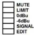
Input channel LEDs
-
Output channel LEDs
-
USB connection - Type B connector for linking to PC
-
LCD Display - Displays parameters and programming menu
-
Menu navigation buttons:
BACK – selects previous menu item
NEXT – selects next menu item
MENU - Enter menu
ENTER – Confirms selection
BYPASS – bypasses process for comparison with unaffected signal
ESCAPE – escapes from current screen
-
Default buttons
-
Input EDIT/MUTE key - Press to mute, press & hold 3sec to edit
-
Output EDIT/MUTE key - Press to mute, press & hold 3sec to edit
Rear Panel Controls and Connectors

-
IEC connector - Mains inlet
-
Power switch - Switches mains power to the DSM48
-
Ventilation grille - Do not cover or obstruct airflow to this vent
-
RJ45 connector - LAN Connection to PC or other DSM48
-
Output connectors - Balanced XLR output connectors
-
Input connectors - Balanced XLR input connectors (analogue or AES digital on inputs A & C)
Panel Operation
Input Parameter Setting
Pressing a Mute/Edit button will Mute or un-mute that specific input.
Press & hold the MUTE/EDIT key for IN A or IN B for 3 seconds to enter edit mode.
Using the BACK and NEXT navigation buttons will step through the various menu options.
1. Input Name
Parameter 1 rotary control selects the letter or figure
Parameter 2 rotary control moves to the next or previous character
Press ENTER to confirm when the name is set as required
2. Input Delay
Delay 0-1000ms / 0-346m / 0-1134.88ft (independent per channel)
Parameter 1 rotary control performs fine adjustment
Parameter 2 rotary control performs coarse adjustment
3. Input Polarity
Polarity [+] Normal / [-] Inverted (independent for each channel)
Parameter 1 rotary control toggles between + and - polarity
4. Input Gain
Gain -40 to +6dB in 0.1dB steps (independent for each channel)
Parameter 1 rotary adjusts the Gain value
5. Input EQ
Input EQ1 - EQ8 (8 independent EQs for each channel)
Press BACK or NEXT buttons to step through EQ1 to EQ8
Parameter 1 rotary selects the filter type:
Parametric (PEQ), High-Shelf (Hi-S) or Low-Shelf (Lo-S)
Press ENTER to confirm the filter type and move down to parameter settings.
Parameter 1 rotary control adjusts the cutoff frequency (20Hz to 20kHz)
Parameter 2 rotary control adjusts the gain (-30 to +15dB)
Parameter 3 rotary control selects bandwidth/slope (0.05-3.00oct or 6-12dB/oct)
Press ENTER to confirm parameter settings
6. Noise Gate
Noise gate threshold -120 to +10dBu
Parameter 1, 2 or 3 rotary controls adjust the gate threshold
Input A:LEFT
Name:
Press ENTER to save
Input A:LEFT
Delay: 0.0625ms
0.0216Metre
0.0709Feet
Input A:LEFT
Polarity:+Normal
Input A:LEFT
Gain: 0.0dB
Input A:LEFT EQ1:Hi-S
Freq: 45Hz
Gain: 0.0dB
Slope: 6dB
Input A:LEFT
Noise Gate:-98dBu
Output Parameter setting
Pressing a Mute/Edit button will Mute or un-mute that specific input.
Press & hold the MUTE/EDIT key for IN A or IN B for 3 seconds to enter edit mode.
Using the BACK and NEXT navigation buttons will step through the various menu options.
1. Output Name
Parameter 1 rotary control selects the letter or figure
Parameter 2 rotary control moves to the next or previous character
Press ENTER to confirm when the name is set as required
2. Signal Source
Select On or Off for signal input A and input B
Parameter 1, 2 or 3 rotary control selects on or off status
Press ENTER to toggle between input A and input B
3. Output Gain
Gain range -40 to +15dBu
Parameter 1 rotary control adjusts output gain
4. Output Polarity
Polarity [+] Normal / [-] Inverted (independent for each channel)
Parameter 1 rotary control toggles between + and - polarity
5. Output Delay
Delay 0-1000ms / 0-346m / 0-1134.88ft (independent per channel)
Parameter 1 rotary control performs fine adjustment
Parameter 2 rotary control performs coarse adjustment
6. Crossover HPF
Crossover High-pass filter settings (independent per channel)
Parameter 1 rotary control adjusts cutoff frequency (20Hz-20kHz)
Parameter 2 rotary control sets filter type (Linkwitz-Riley, Bessel, Butterworth)
Parameter 3 rotary control sets the slope gradient (12/18/24/48dB per octave)
7. Crossover LPF
Crossover Low-pass filter settings (independent per channel)
Parameter 1 rotary control adjusts cutoff frequency (20Hz-20kHz)
Parameter 2 rotary control sets filter type (Linkwitz-Riley, Bessel, Butterworth)
Parameter 3 rotary control sets the slope gradient (12/18/24/48dB per octave)
Output 1:LSUB
Name:
Press ENTER to save
Output 1:LSUB
Source:
InA InB
On Off
Output 1:LSUB
Gain: 0.0dB
Output 1:LSUB
Polarity:+Normal
Output 1:LSUB
Delay: 0.0625ms
0.0216Metre
0.0709Feet
Output 1:LSUB HPF
Freq: 20Hz
Filter: Bessel
Slope: 48dB/oct
Output 1:LSUB LPF
Freq: 20,000Hz
Filter: Bessel
Slope: 12dB/oct
8. Output EQ
Output EQ1 - EQ6 (6 independent EQs for each channel)
Press BACK or NEXT buttons to step through EQ1 to EQ6
Parameter 1 rotary selects the filter type:
Parametric (PEQ), High-Shelf (Hi-S) or Low-Shelf (Lo-S)
Press ENTER to confirm the filter type and move down to parameter settings.
Parameter 1 rotary control adjusts the cutoff frequency (20Hz to 20kHz)
Parameter 2 rotary control adjusts the gain (-30 to +15dB)
Parameter 3 rotary control selects bandwidth/slope (0.05-3.00oct or 6-12dB/oct)
Press ENTER to confirm the parameter settings.
Output 1:LSUB EQ1:PEQ
Freq: 20Hz
Filter: Bessel
Slope: 48dB/oct
9. Output compressor/limiter
Output Compressor or Limiter (independent for each channel)
Parameter 1 rotary control selects Compressor or Limiter. Press ENTER to confirm
In Compressor mode, press BACK or NEXT buttons to toggle between 2 pages:
Page 1: Parameter 1 adjusts the Threshold (-30 to +20dBu)
Page 1: Parameter 2 adjusts the Attack (0.3 to 100ms)
Page 1: Parameter 3 adjusts the Release time (2x, 4x, 6x, 8x, 16x, 32x Attack time)
Page 2: Parameter 1 selects Manual or Auto mode (Auto overrides Page 1 parameters)
Page 2: Parameter 2 adjusts the Clip Limiter (2dB to 12dB above threshold)
Page 2: Parameter 3 adjusts the Ratio (1:1, 1:2, 1:4, 1:8, 1:16, 1:32, 1:64, 1:Max)
Output 1:LSUB
Compressor: Manual
Cliplim: 2.0dB Above
Ratio: 1:16
In Limiter mode, there is only one page of parameters.
Page 1: Parameter 1 adjusts the Threshold (-30 to +20dBu)
Page 1: Parameter 2 adjusts the Attack (0.3 to 100ms)
Page 1: Parameter 3 adjusts the Release time (2x, 4x, 6x, 8x, 16x, 32x Attack time)
Output 1:LSUB
Mode: Limit
Threshold: -30.0dBu
Att:40ms Rel: 4x
Main Menu
Pressing the MENU button enters the main menu for system settings.
The BACK and NEXT buttons or Parameter 1 to navigate through the sub-menus. Press ENTER to select an option.
-
X-over (crossover) 1) Load program, 2) Store program, 3) Erase program
-
Program copy Copy all input and output settings from a stored program to another program
Parameter 1 selects source, Parameter 2 selects target, Press ENTER to copy
- Channel copy Copy all parameter settings from any input or output channel to another channel
Parameter 1 selects source, Parameter 2 selects target, Press ENTER to copy
-
Input Parameter 1 selects between Analogue or Digital (AES) input type
-
Security Parameter 1 = character, Parameter 2 = previous/ next, Press ENTER = lock (or unlock)
-
System 1) Backlight Keep On or Auto-off after 25s
2) System info. Press ENTER to see the system information
3) Temperature: Parameter 1 adjusts the maximum temperature before cut-out
4) Filter Display: Parameter 1 selects filter Bandwidth or Q parameter display
5) Scene change: Enable/disable buttons 1, 2 and 3 as hot keys for 3 favourite programs
6) Scene key setup: Use Parameter 1, 2 and 3 to set Favourites 1, 2 and 3
7) WIFI Factory Reset – not used (future development)
PC Software Operation
Setting up
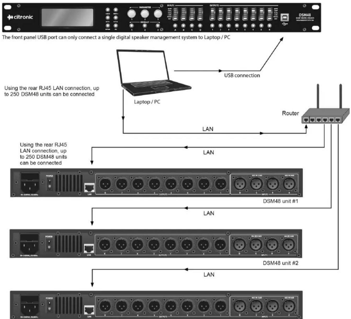
The Citronic DSM48 can be operated individually from a PC via USB and can also be linked in multiples over a wider, long-distance network via LAN connection. A maximum of 250 units may be linked together by this method. If connecting via LAN, see the "LAN Setup" section further on in this document.
Before connecting a DSM48 via USB, install the software from the supplied disc. (also available to download from www.avsl.com)
Locate the driver file "PL2303_Driver" and double click to install (this will usually require a re-start once installed) Connect the DSM48 via USB or LAN as shown below and double click the file named "DSP Ver 3.9"
flowchart
graph TD
    A["citronic"] --> B["The front panel USB port can only connect a single digital speaker management system to Laptop / PC"]
    B --> C["Using the rear RJ45 LAN connection, up to 250 DSM48 units can be connected"]
    C --> D["Laptop / PC"]
    D --> E["USB connection"]
    E --> F["Router"]
    F --> G["Using the rear RJ45 LAN connection, up to 250 DSM48 units can be connected"]
    G --> H["LAN"]
    H --> I["DSM48 unit #1"]
    I --> J["LAN"]
    J --> K["DSM48 unit #2"]
    K --> L["LAN"]
Each DSM48 connected to the network should be set up with a different IP address (via USB) first
DSM48 unit #250
Screen Shot
line
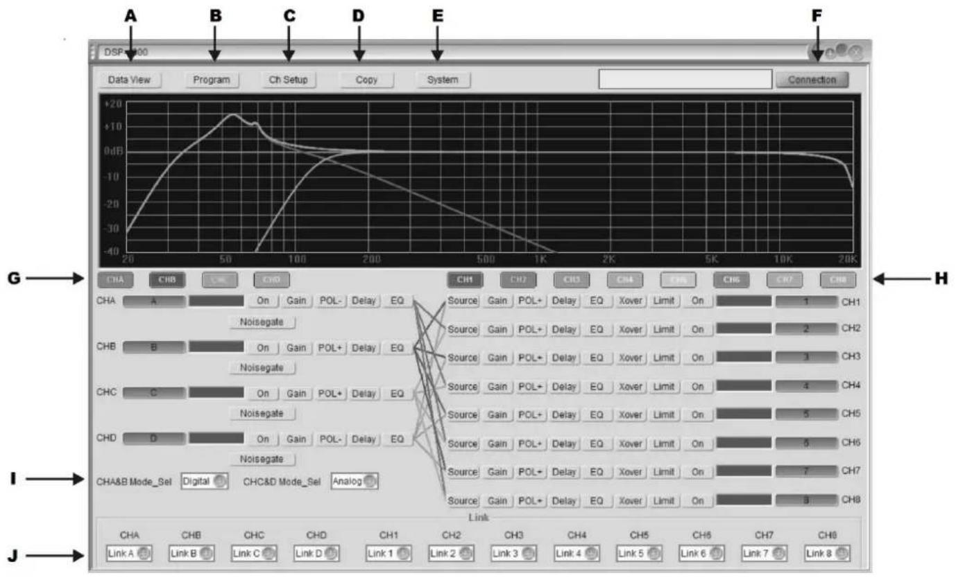
| Channel | Phase | Value | |---------|-------|-------| | CHA | On | -30 | | CHB | On | -10 | | CHD | On | 0 | | CHA | Delay | 0 | | CHB | Delay | 0 | | CHD | Delay | 0 | | CHA | On | 0 | | CHB | On | 0 | | CHD | On | 0 | | CHA | Delay | 0 | | CHB | Delay | 0 | | CHD | Delay | 0 | | CHA | On | 0 | | CHB | On | 0 | | CHD | On | 0 | | CHA | Digital | 0 | | CHB | Digital | 0 | | CHD | Digital | 0 | | CHA | Analog | 0 | | CHB | Analog | 0 | | CHD | Analog | 0 | | CHA | Link | 0 | | CHB | Link | 0 | | CHD | Link | 0 | | CHA | Link A | 0 | | CHB | Link B | 0 | | CHD | Link C | 0 | | CHA | Link D | 0 | | CHB | Link D | 0 | | CHD | Link 1 | 0 | | CHA | Link 2 | 0 | | CHB | Link 3 | 0 | | CHD | Link 4 | 0 | | CHA | Link 5 | 0 | | CHB | Link 6 | 0 | | CHD | Link 7 | 0 | | CHA | Link 8 | 0 | | CHB | Link 8 | 0 | | CHD | Link 8 | 0 | | CHA | Link 8 | 0 | | CHB | Link 8 | 0 | | CHD | Link 8 | 0 | | CHA | Link 8 | 0 | | CHB | Link 8 | 0 | | CHD | Link 8 | 0 | | CHA | Link 8 | 0 | | CHB | Link 8 | 0 | | CHD | Link 8 | 0 | | CHA | Link 8 | 0 | | CHB | Link 8 | 0 | | CHD | Link 8 | 0 | | CHA | Link 8 | 0 | | CHB | Link 8 | 0 | | CHD | Link 8 | 0 | | CHA | Link 8 | 0 |A Display data/curve graph
F Connection menu
B Save / Load Program menu
G Input edit select
C Channel setup
H Output edit select
D Copy channel
I Input source type setting
E System menu
J Channel connect
Connection
In order for the PC to communicate with the DSM48, it is necessary to establish a connection. Click on "Connection" (F)
Connection
The following menu will be displayed
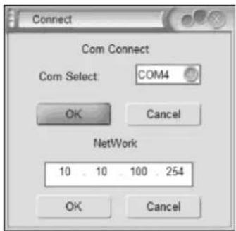
← Communication Port Select
← Network Address Setting
The software will normally be able to detect the correct COM port and this will be displayed.
Click OK to confirm the USB connection between PC and DSM48. If unsuccessful, try a different COM port from the list. If COM port is not detected automatically, open the PC's Hardware Device Manager.
(e.g. "Start-Settings-Control Panel-System-Hardware-Device Manager" or type "Device Manager" into the search box) Look in "Ports" to identify which port is being used for the DSM48.
Select the correct port for the connected DSM48 in the Connection menu (COM4 is shown in the above example)
If connecting via LAN, enter a workable IP address which is not occupied by other equipment into the "Network" field.
Program menu
Clicking on the Program button at the top of the main screen will open the following window.
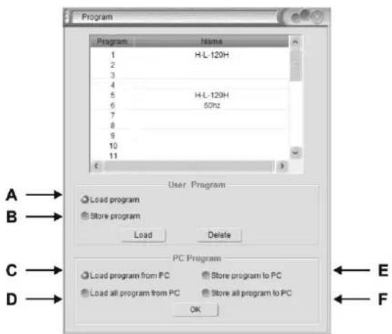
A Load/Delete group user data or effect data from device
B Save/Delete group user data or effect data from device
C Load group user data or effect data from PC
D Load all group user data or effect data from PC
E Save group user data or effect data from PC
F Save all group user data or effect data from PC
To load a program, check button A, click on the program in the list in the top half of the window and then click the Load button.
To delete a program, click on it in the list in the top half of the window and then click the Delete button.
To save a program after editing, check button B, select a blank program or one for over-writing, type a name in the text field and click the Save button.
Selected programs or All programs may be saved to PC or loaded from PC by checking buttons C, D, E or F and clicking "OK"
Channel setup
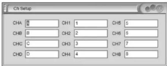
Clicking the Ch Setup button will open the widow shown opposite. Click in each window and type a name for each input and output, then hit return to rename that channel
Copy function
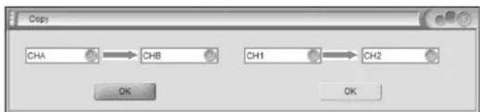
Clicking the Copy button in the main screen will open the widow shown opposite.
Select inputs (left side) or outputs (right side) to copy from and to and click OK to copy all settings across.
System menu
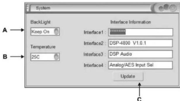
Clicking the System button in the main screen will open the widow shown opposite.
A Select LCD backlight constant or off after 25s
B Select cutoff temperature for the device
C Interface information is shown in the 4 fields on the right side of the window and can be edited by typing directly in each and clicking Update
flowchart
graph LR
    A["CHA"] --> B["CHB"]
    C["CH1"] --> D["CH2"]
    E["OK"] --> F["OK"]
Channel functions
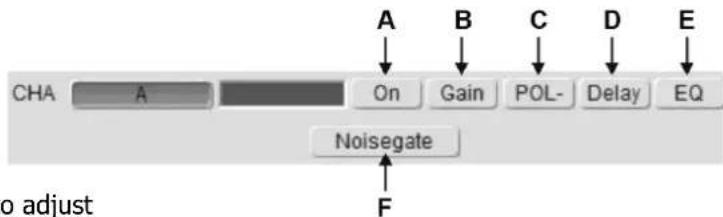
Clicking on an input channel button switches the button between its own colour or grey.
When it is grey, its frequency curve will not be displayed in the top window. Clicking on any of the channel functions button will open an editing window for that function
A Channel Mute or On select
B Input Gain setting
C Normal or Inverted polarity select
D Input Delay time setting
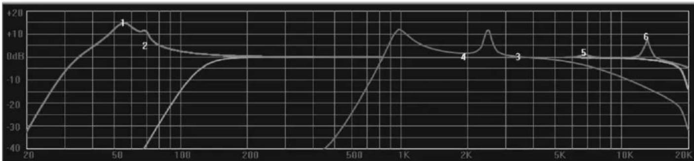
E EQ edit - click & drag EQ 1-8 on the curve graph to adjust centre frequency or stretch bandwidth (see below)
F Noise gate setting
flowchart
graph LR
    A["CHA"] --> B["On"]
    B --> C["Gain"]
    C --> D["POL-"]
    D --> E["Delay"]
    E --> F["EQ"]
    F --> G["Noisegate"]
    G --> H["F"]
In EQ edit mode, click and drag EQ numbers on the curve graph to adjust the centre frequency for each filter
line
| Frequency | Value | | --------- | ----- | | 50 | 1 | | 70 | 2 | | 1K | 4 | | 2K | 3 | | 12K | 6 |Clicking on an output channel button also switches the button between its own colour or grey.
When it is grey, its frequency curve will not be displayed in the top window. Clicking on any of the channel functions button will open an editing window for that function.
Clicking on any function button will enter editing mode for that function.
A Source select (from input A, B or both)
B Output Gain setting
C Normal or Inverted polarity select
D Output Delay time setting
E EQ edit - click & drag EQ 1-8 on the curve graph to adjust centre frequency or stretch bandwidth
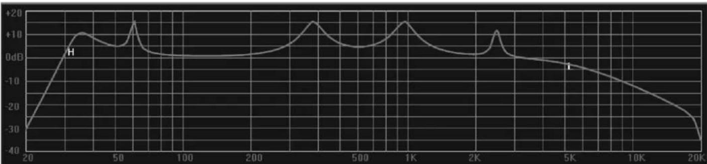
F Crossover edit - click and drag H or L on the curve graph to adjust centre frequency for each filter (see below)
G Compressor/Limiter setting

In Crossover edit mode, click and drag H or L to adjust the centre frequency for each filter
line
| x | y | | ---- | ----- | | 20 | -30 | | 50 | 10 | | 100 | 0 | | 200 | 0 | | 500 | 0 | | 1K | 15 | | 2K | 0 | | 5K | -5 | | 10K | -15 | | 20K | -35 |LAN setup
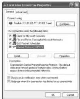
On the PC that is to be connected with the DSM48 (or multiple units), navigate to the network adaptor properties.
e.g. in Windows 10, click the start button and click the settings icon (cog symbol) Select Network & Internet and Ethernet.
Select Change Adapter Options, right click the relevant connection and select Properties. The window opposite should appear, showing network adaptor options.
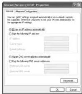
Right click on TCP/IP and the window opposite will appear.
Ensure that the button for Obtain an IP address automatically This will ensure that the PC will connect to the DSM48 unit as a LAN host.
The next step is to connect the PC to the DSM48 unit directly via LAN cable.
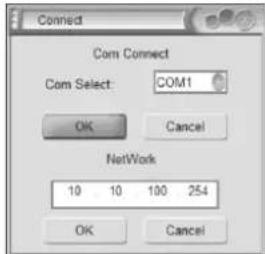
In the DSM48 software main screen, click the Connection button. The window opposite will open, showing the COM port and IP settings. Click OK below the auto-detected IP address and the DSM48 will connect.
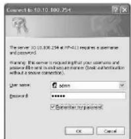
Once connected directly to the PC via LAN cable, it is possible to access the DSM48 network adaptor from the PC by opening a browser window (IE, MS Edge or Chrome etc.) Type in the (auto-detected) IP address of the DSM48 into the address bar of the browser. (e.g. as shown in the connection window opposite, this would be "http://10.10.100.254") A security window will open as follows...
Both User name and Password are "admin" by default. Once logged into the DSM48, an edit window will open, as shown below.
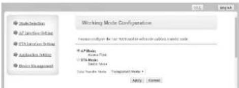
If the display is not in English, click the English button. There are many advanced settings within this menu, which should only be edited by the network administrator but the basic LAN settings are easily set as follows.
Click on the "AP Interface Setting" link and a new window will open to edit network settings.
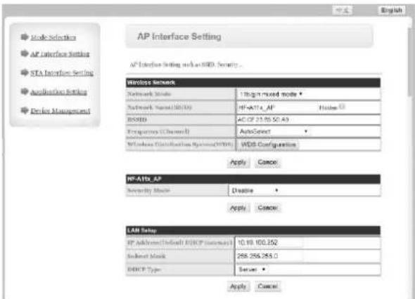
In the AP Interface Setting window, it is possible to edit the IP address of the DSM48 for LAN connection. Enter a new valid IP address into the top field of the "LAN Setup" section (Wireless does not apply to the DSM48 unless modified) Click "Apply" and a message will appear advising... "Set Successfully, Restart to use new setting"
Click on the "Device Management" link. (the login user name and password can be edited here) Click on the "Restart" button and the DSM48 will restart. Note: to log back in, it will be necessary to input the new IP address into the browser address bar (and new user name and password if they have been edited)
The unit can now be connected to the main LAN network and connected by its IP address in the DSP Ver3.9 application.
Specifications
| Power supply | 115/230Vac, 50/60Hz (IEC) |
| Power consumption | <25W |
| Fuse | T315mA |
| Crossover | HPF + LPF fully programmable per output |
| Filter type | Linkwitz-Riley; Bessel; Butterworth. |
| PC Com port | USB and LAN (RJ45) |
| CMRR | 65dB (50Hz-10kHz) |
| Input type | Analogue or AES digital (XLR) |
| Input/output polarity | In phase (+) or reverse (-) |
| Input EQ | 8-band parametric EQ |
| Input Noise Gate | -120dBu to +10dBu |
| Processor | 96kHz, 32-bit floating point DSP |
| Mute | Any input or output channel |
| Limiter | 6 x output (adjustable) Compressor/Limiter |
| Output EQ | 8-band: Hi/Lo-shelf or Parametric |
| Delay | 0-1000ms per output |
| Frequency response | 20Hz-20kHz |
| Input impedance : balanced | >10k Ohms |
| Output impedance : balanced | <60 Ohms |
| Dimensions | 482 x 44 x 220mm |
| Weight | 3.19kg |



Disposal: The "Crossed Wheelie Bin" symbol on the product means that the product is classed as Electrical or Electronic equipment and should not be disposed with other household or commercial waste at the end of its useful life. The goods must be disposed of according to your local council guidelines.
Errors and omissions excepted. Copyright© 2021.
AVSL Group Ltd. Unit 2-4 Bridgewater Park, Taylor Rd. Manchester. M41 7JQ
AVSL (EUROPE) Ltd, Unit 3D North Point House, North Point Business Park, New Mallow Road, Cork, Ireland
- Features
- Version 1.1
- Introduction
- Contents
- Safety Instructions
- Front Panel Controls and Connectors
- Rear Panel Controls and Connectors
- Panel Operation
- Input Parameter Setting
- Input Name
- Input Delay
- Input Polarity
- Input Gain
- Input EQ
- Noise Gate
- Output Parameter setting
- Output Name
- Signal Source
- Output Gain
- Output Polarity
- Output Delay
- Crossover HPF
- Crossover LPF
- Output EQ
- Output compressor/limiter
- Main Menu
- PC Software Operation
- Setting up
- Connection
- Program menu
- Channel setup
- Copy function
- System menu
- Channel functions
- LAN setup
Brand : Citronic
Model : DSM48
Category : Loudspeaker