
MX100 - AV amplifier MCINTOSH - Free user manual and instructions
Find the device manual for free MX100 MCINTOSH in PDF.


| Product Type | A/V Processor |
| Brand | McIntosh |
| Model | MX100 |
| HDMI Inputs | 4 (HDMI 2.0, 18 Gbps, 4K@60Hz, HDR, Dolby Vision, HDCP 2.2) |
| HDMI Output | 1 (eARC/ARC) |
| Digital Audio Inputs | 2 coaxial, 2 optical (Toslink) |
| Analog Audio Outputs | 13 balanced XLR (Front L/R, Center, Surround L/R, Surround Back L/R, Height 1 L/R, Height 2 L/R, Subwoofer 1/2) |
| Room Correction | Audyssey MultEQ XT32 with Dynamic Volume and Dynamic EQ |
| Surround Formats | Dolby Atmos, DTS:X, Dolby Surround, DTS Neural:X |
| Network | 10baseT LAN, DHCP, web browser setup |
| Control | RS232, IR input, 2 Power Control (trigger) outputs |
| USB Port | 1 type-A (firmware updates, configuration backup) |
| Microphone Input | 1/8" jack for included Audyssey calibration mic |
| Dimensions (W x H x D) | 17-1/2" x 4-15/16" x 21" (44.5 x 12.5 x 53.3 cm); with rack brackets: 19" W (48.3 cm) |
| Weight | 17 lb (7.7 kg) net, 39.5 lb (18 kg) shipping |
| Power Consumption | 30 W (standby <0.5 W) |
| Voltage | Factory configured for 100V–240V, 50/60 Hz |
| Remote Control | HR085 (included) |
| Package Contents | MX100, microphone, stand, rack brackets, remote, power cord, manual |
| Safety & Maintenance | Ensure adequate ventilation; do not block vents. Clean with soft dry cloth. Avoid liquids. Refer to separate safety guide. |
| Spare Parts & Repairability | Remote batteries (AAA), optional service remote HR093, rack mount brackets. Contact McIntosh for service. |
Frequently Asked Questions - MX100 MCINTOSH
User questions about MX100 MCINTOSH
0 question about this device. Answer the ones you know or ask your own.
Ask a new question about this device
Download the instructions for your AV amplifier in PDF format for free! Find your manual MX100 - MCINTOSH and take your electronic device back in hand. On this page are published all the documents necessary for the use of your device. MX100 by MCINTOSH.
USER MANUAL MX100 MCINTOSH
McIntosh Laboratory, Inc. 2 Chambers Street Binghamton, New York 13903-2699 Phone: 607-723-3512 www.mcintoshlabs.com
MX100
A/V Processor
Owner's Manual


The MX100 Audio/Visual Processor marries a long tradition of uncompromising quality with the latest home theater technologies to bring you an unsurpassed luxury entertainment experience.
Thank you from all of us at McIntosh
With the MX100 A/V Processor, you have invested in a precision instrument that will provide you with many years of enjoyment. Please take a few moments to familiarize yourself with the features and instructions to get the maximum performance from your equipment.
If you need further technical assistance, please contact your dealer who may be more familiar with your particular setup including other brands. You can also contact McIntosh with additional questions or in the unlikely event of needing service.
McIntosh Laboratory, Inc.
2 Chambers Street
Binghamton, New York 13903
Technical Assistance: (607) 723-3512
Customer Service: (607) 723-3515
Fax:(607) 724-0549
Email: support@mcintoshlabs.com
Website: mcintoshlabs.com
Make a Note
For future reference, you can jot down your serial number and purchase information here. We can identify your purchase from this information if the occasion should arise.
| Serial Number: | |
| Purchase Date: | |
| Dealer Name |
Table of Contents
Thank you from all of us at McIntosh 2
Make a Note....2
Safety First....4
Trademark and License Information .... 5
What is in the box....6
Where to put it 6
Making the Cuts....7
Rack Mounting 7
The Front Panel....8
The Left Knob (INPUT)......8
The Right Knob (VOLUME)....8
Connections on the Back 9
The Inputs....9
The Outputs 9
Making Connections....9
10baseT LAN 9
HDMI 9
USB 9
Microphone....9
5.1 Connection Diagram 10
RS232....11
Wired IR Inputs 11
Digital Inputs 11
AC Power 11
Balanced Audio Outputs....11
Power Control (Trigger) Outputs 12
Data Out....12
Settings 12
Entering Setup 13
Determining the IP Address....13
Exiting Setup 13
Navigating Setup with the Remote Control ...13
Setup from a Browser....14
Audio Setup Menu....14
Surround Mode....14
Video Setup Menu 16
Inputs Setup Menu....17
Speakers- Setup Menu 18
Amp Assign.... 18
Speaker Configuration.... 19
Crossovers....19
Bass Type....19
Speaker Distances....20
Test Tones & Levels....20
Network Setup Menu....20
General Setup Menu 20
Factory Reset 20
Remote Control Buttons 23
Additional Discrete Commands....23
Remote Control Batteries 23
Audyssey ^3 24
Audyssey Procedure Overview 24
Audyssey Setup 24
Begin Audyssey 25
Error Messages 26
The Trim Menu 28
Trim Menu Using the Remote Control....28
Trim Menu Using Knobs 28
More on Trim Settings 28
Supported HDMI Signals 29
Packing the MX100 30
Audio Specifications 31
Video Specifications....31
General Specifications 31
List of Figures
Figure 01- MX100 Dimensions....6
Figure 02- Custom cutout dimensions....7
Figure 03— Rack Mount screws....7
Figure 04—Installing Rack Mount Bracket.....7
Figure 05- Front Panel 8
Figure 06- MX100 Rear View....9
Figure 07- Example 5.1 connection diagram .... 10
Figure 08- Mini plug for RS232 connection..... 11
Figure 09- DB9 connector pin layout .... 11
Figure 10— IR 3.5mm connector.... 11
Figure 11- Setting the Remote Control Lock.... 11
Figure 12- Power Control (trigger) mini plug.... 12
Figure 17- Input Aduct 17
Figure 18– Dolby Enabled speakers.... 19
Figure 19- Audyssey® main listening position.. 24
Figure 20- Speaker angles 24
Figure 21—Microphone stand with Microphone 24
Figure 22- Audyssey Setup Microphone Jack .. 25
Figure 23- Audyssey Setup intro 25
Figure 24- Audyssey Setup Begin.... 25
Figure 25- Audyssey Setup position 0....25
Figure 26– Audyssey measurements complete .. 26
Figure 27- Saving Audyssey calibration....26
Figure 28- Audyssey error table 27
Figure 29 Remote Control Trim buttons ..... 28
Figure 30- Re-packing diagram....30

Safety First
Important Safety Information is supplied in a separate document "Important Additional Operation Information Guide"
Trademark and License Information
The McIntosh MX100 incorporates copyright protected technology that is protected by U.S. patents and other intellectual property rights. The MX100 uses the following technologies:
This item incorporates copy protection technology that is protected by U.S. patents and other intellectual property rights of Rovi Corporation. Reverse engineering and disassembly are prohibited.
| Trademark Logo License Information | |
| DOLby AtmosDOLby Audio | Dolby, Dolby Atmos, and the double-D symbol are registered trademarks of Dolby Laboratories Licensing Corporation. Manufactured under license from Dolby Laboratories. Confidential unpublished works. Copyright © 2012-2020 Dolby Laboratories. All rights reserved. |
 | The terms HDMI, HDMI High-Definition Multimedia Interface, and the HDMI Logo are trademarks or registered trademarks of HDMI Licensing Administrator, Inc. |
 | Manufactured under license from Audyssey LaboratoriesTM. U.S. and foreign patents pending. Audyssey MultEQ®XT32, Audyssey Dynamic EQ®and Audyssey Dynamic Volume®are registered trademarks of Audyssey Laboratories. |
 | For DTS patents, see http://patents.dts.com. Manufactured under license from DTS Licensing Limited. DTS, DTS:X, and the DTS:X logo are registered trademarks or trademarks of DTS, Inc. in the United States and other countries. © 2021 DTS, Inc. ALL RIGHTS RESERVED. |

What is in the box
Here is what is in the box besides all the shipping foam:
One MX100 A/V Processor
One accessory package including:
- Microphone with attached cable
- Microphone stand
• 1/2 inch male to 5/8 inch female adapter
One hardware package:
- Two Side Rack Mounting brackets
- 4 flat head Philips screws 6-32x1/4"
• 4 flat head Philips screws 8-32x1/4"
One manual package including this manual
One HR085 Remote Control
One AC power cord
Where to put it
The MX100 can be placed upright on a table or shelf, standing on its four feet. It also can be custom installed in a piece of furniture or cabinet. The four feet may be removed for custom installations. The four feet together with the mounting screws should be retained for possible future use. Do not use
different size screws when re-installing the feet. With the feet removed, the MX100 requires a ventilation cutout. Dimensions for the panel cutout and bottom ventilation cutout are shown in "Figure 02- Custom cutout dimensions" on page 7.
Always provide adequate ventilation for your MX100. Cool operation ensures the longest possible operating life for any electronic instrument. Do not install the MX100 directly above a heat generating component such as a high-powered amplifier. If all the components are installed in a single cabinet, a quiet running ventilation fan can be a definite asset in


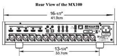

Figure 01- MX100 Dimensions
maintaining all the system components at the coolest possible operating temperature.
A custom cabinet installation should provide the following minimum spacing dimensions for cool operation:
• 2 inches (5.1cm) above the top
• 2 inches (5.1cm) below the bottom
- 1 inch (2.5cm) on each side of the MX100 so that airflow is not obstructed
• 20 inches (50.8cm) depth behind the front panel
- 1-7/16 inch (3.7cm) in front of the mounting panel for knob clearance
Be sure to cut out a ventilation hole in the mounting shelf according to the dimensions in the drawing. See Figure 02 on page 7.
Making the Cuts
Here are the dimensions for the cutouts needed for custom installation. A ventilation opening is essential for any installation with the four feet removed.

Figure 02 Custom cutout dimensions
Rack Mounting
To rack mount the MX100, the two included Side Rack Mount Brackets should be installed. Follow these instructions for each side:
- Remove the two screws from the front side of the MX100's side panel
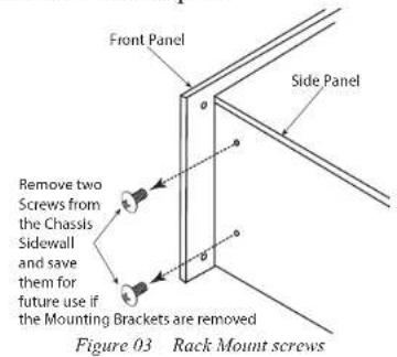
- Secure the Side Rack Mounting Bracket to the MX100 using the larger supplied screws. Do not re-use the previously removed screws. Use the smaller supplied screws to secure the bracket to the Front Panel.

Figure 04 Installing Rack Mount Bracket

The Front Panel
The MX100's glass and metal Front Panel provides two control knobs and an informational display.
The Left Knob (INPUT)
The Left Knob, labeled Input, is used to change inputs, enter Trim setting mode and to enter Setup mode.
- Turn clockwise or counterclockwise to scroll through inputs
- Push and release to enter Trim mode
- Push, hold and release after 2 seconds to enter Setup mode
The Right Knob (VOLUME)
The Right Knob, labeled Volume, is used to change the volume as well scroll through input values within Trim Mode. Push and release the knob to
toggle Mute on and off. Push and hold the Knob to Power Off. Push the Right Knob to Power On when the MX100 is off,
- Turn clockwise or counterclockwise to scroll through input values in Setup mode or Trim mode
- Push and release to Power On when MX100 is Off
- Push and hold for two seconds seconds to Power Off. POWER OFF will appear on the display
- Push and release to toggle Mute on/off when MX100 is On

Figure 05— Front Panel

Connections on the Back
The Inputs
Four HDMI Inputs
Two coaxial digital audio Inputs
Two Toslink optical Inputs
One 10baseT LAN connector
One 1/8 inch jack for microphone Input
One 1/8 inch jack for RS232 connector
One 1/8 inch jack for wired IR Input
One USB upgrade service port
One AC power connector
The Outputs
One HDMI OUT/eARC (also acts as an audio input when ARC is active)
13 balanced XLR audio Outputs
Two 1/8 inch jack Power Control (trigger) Outputs
One 1/8 inch Data Output jack
Making Connections
10baseT LAN
Use an Ethernet cable to connect the MX100 to a network router. The network connector is located on the top rear of the MX100 to the left of the CAUTION label. It is labeled NET.
By default, the MX100 has DHCP set to ON and will automatically receive an IP address from the router. This setting can be changed.
HDMI
The MX100 has 4 HDMI Inputs. A high-performance HDMI cable is recommended to take advantage of the 18 Gbps speed capabilities of all 5 HDMI ports. The HDMI cables should support 4K@60Hz, and YCbCr 4:2:2 (4:4:4/RGB) as well as Ethernet and ARC. Cables designed for HDMI 2.0 are fine. Though HDMI is backward compatible, older cables may have issues with the higher bandwidth.
Use HDMI OUT/eARC when connecting to an ARC (Audio Return Channel) enabled television (or any HDMI capable TV).
ARC can provide two-way communication between units allowing for volume control and lip-syncing functions to ensure audio and video are perfectly matched. This allows for more intelligent operation between components as well as less cable clutter. Make sure the ARC is enabled in your TV's setup menu.
The MX100 supports eARC. eARC allows for even higher bandwidth and will allow for higher quality audio including uncompressed 7.1 surround, Dolby Atmos and DTS:X.
USB
There is a type-A port on the rear of the MX100 which is labeled USB 5V/1A. The USB port is used for firmware upgrades and to save and restore MX100 setup information. The USB port IS NOT for general USB use or charging devices.
Microphone
The SETUP MIC Input is for connecting the supplied MX100 Microphone using the microphone's attached cable and an 1/8 inch connector. The microphone is used in the Audyssey® calibration for tuning the system to your room. For instructions see "Audyssey®" on page 24.

5.1 Connection Diagram

Figure 07- Example 5.1 connection diagram
7 Channel Power Amplifier (You may have separate amplifiers)
RS232
The RS232 jack is used to connect the MX100 to automation controller devices with RS232 connectors. To utilize this feature, you will need an appropriate RS232 Data Cable. The RS232 Data Cable should be an 1/8 inch (3.5mm) stereo mini phone plug to a subminiature DB9 connector.

Figure 08—Mini plug for RS232 connection

Figure 09- DB9 connector pin layout
RS232 DB9 Connector Pin Layout
- N/C (no connection) 6. N/C
- Data In (RXD) 7. N/C
- Data Out (TXD) 8. N/C
- N/C 9. N/C
- Gnd
Typical RS232 settings are:
- 8 data bits, no parity and one stop bit
- Baud rate fixed at 115,200 bits per second
Wired IR Inputs
The IR Input allows an external IR receiver to be attached to the MX100. The Input is labeled IR IN. By attaching an IR receiver using a 3.5mm cable (see Figure 10), the MX100's Remote Control can be used in another location without a line-of-sight to
the MX100's front IR sensor.

Figure 10 IR 3.5mm connector
The IR Input is configured for non-McIntosh IR sensors such as a Xantech Model DL85K Kit. If using an external IR receiver for the MAIN ZONE in the same room as the MX100, you may wish to disable the front IR sensor, which also controls the MAIN ZONE. This will avoid potential timing issues of receiving the Remote Control's commands from two different Inputs. The front IR can be turned on/off in the GENERAL section of the SETUP MENU.
Setup>GENERAL>RCLock
To use the front panel to disable or enable the IR sensor (easier using Setup through a browser):
- Press and hold the LEFT Knob for two seconds to enter the Setup menu
- Rotate the Left Knob until you see GENERAL on the display
- Press and release the Left Knob
- Rotate the Left Knob until you see SETUP: GENERAL RC LOCK on the display
- Press and release the Left Knob
- Rotate the Right Knob to select On or Off
SETUP: RC LOCK ON
Figure 11- Setting the Remote Control Lock
RC LOCK ON will disable the front IR sensor so it will not detect Remote Control input (and possibly cause interference with a wired IR input). To enable the IR sensor to detect a Remote Control's IR data, set RC LOCK to OFF (the default).
Digital Inputs
There are four digital Inputs in the MX100:
- Two Toslink Optical Inputs
- Two Coaxial Digital Audio Inputs
The two Coaxial Inputs are labeled:
• COAX 1
• COAX 2
The two Optical Inputs are labeled:
• OPT 1
• OPT 2
The default names and assignments can be changed in setup.
The Optical Inputs require a Digital Optical Audio Cable Toslink Cable. The Coaxial Inputs use Digital Audio Coaxial Cables with male RCA type connectors.
AC Power
This connection is essential. Plug the female end of the supplied AC Power Cord into the AC connector located in the rear right corner of the MX100. Plug the male end of the AC Power Cord into a grounded and functioning AC outlet.
Balanced Audio Outputs
There are 13 male balanced XLR connections on the back of the MX100 to accommodate a wide variety of speaker configurations. Connect balanced XLR cables to the corresponding powered speakers or amplifiers. Here are the possible connections:
- FR (Front Right)
- FL (Front Left)
• C (Center)
• SR (Surround Right)

• SL (Surround Left)
• SBR (Surround Back Right)
• SBL (Surround Back Left)
• HR1 (Height Right 1)
- HL1 (Height Left 1)
- HR2 (Height Right 2)
- HL2 (Height Left 2)
• SW1 (Subwoofer 1)
• SW2 (Subwoofer 2)
HR1 and HL1 should be forward of HR2 and HL2. The MX100 support of Height speakers is limited to Top Front, Top Middle and Top Rear locations.
Setting up speakers for a surround setup takes planning, measuring and installation. Depending on your level of expertise and available time, you may wish to employ the services of your McIntosh dealer for expert setup of your system. Professional installation of in-ceiling speakers is particularly important due to gravity and the location above your head.
The number, types and locations of speakers are key elements in setting up the system. There is a multitude of possible configurations, and the MX100 is very flexible in its setup to adapt to many of these configurations.
Often surround setups are referred to by numbers for example 7.2.4. The first number refers to the number of traditional "floor" speakers (front, center and surround). The second number is the number of subwoofers that can be connected, and the third number refers to the number of in-ceiling or upward firing speakers in the setup.
The type of speaker (size and location) will be entered later during Speaker setup. The distance of the speaker from the listening location is manually entered in the Speaker setup, or automatically
entered during the Audyssey® calibration process. At this stage, the connection from the MX100 to the various amplifiers and powered speakers should be made using quality balanced XLR cables.
Power Control (Trigger) Outputs
The MX100 has two Power Control Outputs or Triggers. Power Control enables power on/off signals to go to connected components so that other components can automatically power on (or off) as called for by the MX100. For example, you may want a DVD player and a certain monitor to power on when HDMI 1 Input is selected, or you may want all components to power off when powering off the MX100. For Setup instructions see Trigger1 and Trigger2 on page 21.
Connect components using a 3.5mm stereo mini plug.

Figure 12- Power Control (trigger) mini plug
Data Out
The MX100 will convert IR Remote Control data to share with McIntosh components connected to the Data Ports. This will allow the operation of primary functions of a source to be operated with the MX100's Remote Control as well as allow units that are out of range of an IR signal to receive commands.
There are two ways to change the settings of the MX100.
- Front Panel Method using the Vacuum Flou
rescent Display (VFD) and Left Knob or
Remote Control
• Using a browser on a connected computer
Each method follows the same menu structure. Most will find it easier to navigate and enter information on a computer. If you don't have a connected computer or the MX100 is not connected to your network, then using the Front Panel method can accomplish almost all the same things using some additional patience.
To use the browser method, you will need the IP address of the MX100. This can be determined using the Front Panel Method. After the example below of determining the MX100's IP Address, the browser method will be used for examples to follow in this manual. The submenus outlined for the browser menus are the same for the Front Panel Menu. Clicking the mouse button and selecting with the Left Knob will traverse the MX100's Setup in the same way. To go back in the Front Panel Method, turn the Left Knob clockwise. The last menu choice is always "Menu Back". Choose Menu Back to go to the previous menu.
In this manual, submenus are denoted in the style:
Setup>SPEAKERS>Floor Layout
which means from the Setup menu choose the SPEAKERS submenu then choose Floor Layout.
Entering Setup
To enter Setup mode using the Vacuum Fluorescent Display (VFD):
- Press and hold the Left Knob for Two seconds and then release
(A short push of the Left Knob will bring up Trim settings. See “The Trim Menu” on page 28.)
Determining the IP Address
Setup>Network>Information>IP Address
- In Setup Mode, turn the Left Knob and scroll to Network
- Select by pushing the left knob
- Scroll to Information and select
- Scroll to IP Address and select
- Note the IP Address
Exiting Setup
To exit Setup, push and hold the Left Knob for two seconds.
To return to a previous menu, scroll down to last menu choice which will be MENU BACK. Select MENU BACK by pushing and releasing the LEFT KNOB. On the top most menu, the last menu choice will be MENU OFF which will exit Setup.
The Setup Menu will time out after 30 seconds of no user input.

Figure 14- Browser Setup Menu
Navigating Setup with the Remote Control

Figure 15- Setup using the Remote Control
Enter the Setup Menu by pressing the Setup button (A). The Setup Button has a blue circle on it. You can scroll through the Setup options by pressing the Up Arrow (B) or Down Arrow (C) on the silver ring.
Push the SELECT button (G) to choose an option to change.
Use the Left Arrow (D) and Right Arrow (E) on the silver ring to change values for the selected Setup option. The new value will be saved automatically.
You may use the Up Arrow (B) or Down Arrow (C) to view another option.
The Mode/Exit button (F) will navigate up a menu level or exit from the top menu just as selecting MENU BACK or MENU OFF will.
The Setup Menu will close after 30 seconds of inactivity.

Setup from a Browser
Setup is easier from a web browser. Open a browser window on a computer connected to the same network as your MX100. Enter the IP address for the MX100 (see "Determining the IP Address" on page 13) in the address bar of your browser.
The Setup Menu (see Figure 16) has seven main submenus.
- Audio
- Video
- Inputs
- Speakers
- Network
- General
- Audyssey
Audio Setup Menu
Setup>Audio
The Audio menu is divided into two main submenus:
- Audio Adjust
- Audyssey
In the Audio Adjust submenu, the following can be adjusted:
- Subwoofer Level Adjust
- Bass Sync
• Audio Delay (Lip Sync) - Volume Scale
• Volume Scale (Linear or dB Level) - Volume Limit
- Surround Mode Music
- Surround Mode Movie
- Surround Mode Game
Subwoofer Level Adjust
Subwoofer Level Adjust allows for adjusting your attached Subwoofer to be adjusted from -12dB to +12dB.
Bass Sync
For contents recorded in multi-channel such as Blu-ray discs, the recorded Low Frequency Effects (LFE) may be out of sync and delayed. This function allows you to correct the delay with an adjustment of 0 ms to 16 ms.
Audio Delay (Lip Sync)
Audio Delay compensates for incorrect timing between video and audio. When Auto Lip Sync is set to On, the timing difference will be automatically corrected with compatible TVs.
The Adjust option allows you to manually adjust the delay correction from the Default of 0 ms up to 500 ms.
Volume Scale
There are two choices for how to display the Volume. The default is a Volume Scale Linear which displays the volume on a scale of 0 (mute) to 99. The second option is Volume Scale dB Level. This will express the volume as decibel (dB) level. The decibel scale is from -103.0dB (mute) to 18dB. Note the displayed dB scale increments are not uniform as they have been designed to give a meaningful level adjustment depending on the actual level being listened to.
Volume Scale Linear/dB Level
You can change the current volume level of the MX100 using the slider. Slide towards the right to increase. (Left will decrease the volume level.) The current volume percentage for the linear scale or dB for the dB scale will appear in the box to the right.
Volume Limit
Volume Limit can protect equipment and/or ears from unintended extreme volume by setting an upper threshold for how high the volume level can be set. Volume Limit can be set to Off (the default) or to one of these three volume limits:
- 60 (-1.5dB)
• 70 (3.5dB)
• 80 (8.5dB)
If Volume Limit is not Off, the MX100's volume level can not be set above the selected Volume Limit.
Surround Mode
In the Surround Mode setup, you can assign a Surround Mode to each of three sound categories:
- Music
- Movie
- Game
These three sound categories can be quickly assigned to an input using the Trim Menu.
Categories make it easier for someone unfamiliar with DTS or Dolby to select the proper Surround Mode by selecting Music, Movie or Game which can be assigned to any of the following choices in Setup:
- AUTO (default)
- Dolby Surround
- DTS Neural:X
• Multi-Channel Stereo - Stereo
Auto
Auto will always send audio to all configured speakers no matter the input audio stream type. It will use Dolby Surround to send audio to all configured speakers if the incoming audio stream is
Dolby encoded. It will use DTS Neural:X to send audio to all configured speakers if a DTS encoded audio stream comes in. If a 2 channel or multi-channel PCM stream comes in, it will use Dolby Surround to send audio to all configured speakers.
Dolby Surround will invoke Dolby's post processor to always send audio to every configured loudspeaker no matter the input stream type.
DTS Neural:X will invoke DTS' post processor to always send audio to every configured loudspeaker no matter the input stream type.
Multi-Channel Stereo will downmix and/or upmix to send audio to all Left and Right floor speakers (plus sub if configured) no matter the input stream type.
Stereo will downmix to send audio to only the Left and Right front speakers (plus sub if configured) no matter the input stream type.
Through will neither upmix or downmix. The input stream will be sent to the configured speakers per the input file stream with no post processing. In the Trim Menu (see "The Trim Menu" on page 28), the current input can be assigned to:
- Music
- Movie
• Game - Auto
- Through
The Surround Mode represented by the Trim selections Music, Movie and Game must be assigned in Setup. If no assignment has been made, the Default for each is Auto.
Audyssey
In the Audio Setup menu, three Audyssey setting can be adjusted:
- MultEQ
- Dynamic Volume
• Dynamic EQ Offset

Figure 16- Audyssey ^3 in Audio Menu
MultEQ XT32 optimizes the frequency response of your speakers. It compensates for both time and frequency characteristics of the listening area based on Audyssey ^® Setup.
MultEQ menu options:
- Reference
- Flat
The default setting is Reference. Reference provides a compensation curve that is optimized for movies with a slight roll off at the higher frequencies. With the volume set for 0dB (63%), you will be hearing the mix at the same level the mixers heard it. The Flat setting is optimized for small rooms where your listening position is closer to the speakers. Keep in mind that many movie soundtracks are optimized for large theaters. The options in the Audyssey® setup section help maintain the theater experience in smaller spaces as well as at lower volumes. The Flat setting utilizes the Audyssey room correction curves without the additional compensations for movie mixing.
Dynamic EQ solves the problem of deteriorating sound quality as volume is decreased by taking into account human perception and room acoustics. Dynamic EQ can be turned On and Off in the Trim Menu (see "The Trim Menu" on page 28). If it is On (the default), the Reference Level Offset option appears. Audyssey ^4 Dynamic EQ ^* is referenced to the standard film mix level. It makes adjustments to maintain the reference response and surround envelopment when the volume is turned down from 0dB. However, film reference level is not always used in music or other non-film content. Dynamic EQ Reference Level Offset provides three offsets from the film level reference (0dB, 10dB, and 15dB) that can be selected when the mix level of the content is not within the standard.

| Offset | Content |
| 0dB (Default) Optimized for movies | |
| 10dB Select this setting for jazz or other music that has a wider dynamic range. This setting should also be selected for TV content as that is usually mixed at 10dB below film reference | |
| 15dB Select this setting for pop/rock music or other program material that is mixed at very high listening levels and has a compressed dynamic range | |
Dynamic Volume
Dynamic Volume solves the problem of large variations in volume level between TV, movies and other content (between quiet passages and loud passages, etc.) by automatically adjusting to the user's preferred volume setting.
The settings available for Dynamic Volume ranging from least to most adjustment are:
• Light
- Medium
- Heavy
Medium is the default set if Dynamic Volume is set to On in the Trim Menu (see “The Trim Menu” on page 28). Dynamic Volume can be turned off using the Trim menu. The setting chosen in setup for Dynamic Volume is utilized for all channels when not turned off. Enabling Dynamic Volume will also enable Dynamic EQ.
Video Setup Menu
Setup>Video
The Video Setup Menu has breaks into two submenus:
- HDMI Setup
- On Screen Display
The HDMI Setup Menu has six submenus:
- Pass Through
• CEC - ARC
• TV Audio Switching - Power Off Control
- Power Saving
The On Screen Display menu has one submenu:
• Volume
Setup>Video>HDMI Setup>Pass Through
Pass Through (written as HDMI PASSTHRU on the front display) allows an HDMI Input to be assigned so that when a signal is received by that HDMI input, while in standby mode, the MX100 will pass the complete signal to the HDMI output exactly as it was received for video and audio playback by a connected TV or monitor.
To avoid unexpected results when using the Pass Through feature, such as your TV powering on your MX100, CEC should be disabled in setup.
| Setting Values | |
| HDMI PASSTHRU OFF | (default) |
| HDMI 1 | |
| HDMI 2 | |
| HDMI 3 | |
| HDMI 4 |
Setup>HDMI Setup>ARC
Use HDMI connection labeled OUT/ARC when connecting to an ARC (Audio Return Channel) enabled television.
ARC can provide two-way communication between units allowing for volume control and lip-syncing functions to ensure audio and video are perfectly matched. This allows for more intelligent operation between components as well as less cable clutter. Make sure the ARC is enabled in your TV's setup menu as well as on the MX100.
| Setting Values | |
| ARC Off | On (default) |
Setup>HDMI Setup>CEC
CEC (Consumer Electronics Control) is an addition to the HDMI standard which allows control signals from one device to communicate with another device via an HDMI cable connection. If you change HDMI Control settings, reset power to connected devices.
Make sure CEC is enabled on all devices you wish to utilize CEC.
| Setting Values | |
| CEC Off | On (default) |
Notes about ARC and CEC
To use ARC, CEC must also be set to On. To use CEC and the additional commands of TV Audio Switching, Power Off Control and Power Saving, CEC must be set to on, so your television and MX100 can better communicate.
The world of ARC and CEC is not yet perfect. It is certainly getting better, but not every component in the world is speaking precisely the same language.
There may be circumstances where you may have better performances by turning these features off. These features can be enabled or disabled at any time on the MX100.
Remember to enable CEC on your television if you want to use CEC with the MX100.
CEC should also be set to Off, if you are using a third-party control system so that CEC does compete with your external controller.
The ARC feature, when enabled, will work with the TV Audio input and a television connected to the HDMI OUT/ARC connection.
TV Audio Switching, Power Off Control and Power Saving are only available options if CEC is turned On.
| Setting Value | |
| TV Audio Switching On | Off (default) |
| Power Off Control All (default)VideoOff | |
| Power Saving On | Off (default) |
TV Audio Switching, when On, will select TV Audio when receiving a command from the TV. Power Off Control, when All, the MX100 will enter Sleep mode when the TV is turned off regardless of input. When Power Off Control is set to Video, the MX100 will enter Sleep mode when the TV is turned off and the MX100's input is set to an HDMI input. Set to Off, the TV's power will not effect the MX100's Standby mode.
Power Saving, when On, will put the MX100 in Sleep mode if the audio source is TV and the TV's audio output is set as the TV's speaker. Power Saving will apply when the MX100 is using an
HDMI input.
On Screen Display, when On, will display the volume on an attached TV when the volume is activated. Off will disable this feature.
| Setting Value | |
| Volu me Off | Bottom (default)Top |
Bottom and Top refer to the position on the TV where the volume will be displayed. Both Bottom and Top enable (on) the On Screen Display feature.
Inputs Setup Menu
Setup>Inputs
The Inputs Menu allows you to customize the name of an input as it will appear on the display. Unused inputs can also be hidden so as not to appear as choices. They can also be easily restored when needed. Note that an Input's name can only be changed through the browser interface.
The Input Adjust section of the Inputs Menu allows you to set a Trim Level for a Source.
| Setting Values | |
| Input HDMI 1 | HDMI 2HDMI 3HDMI 4HDMI TVOPT 1OPT 2COAX 1COAX 2 |
If you are adjusting the setting using the MX100's display, the current Input will be adjusted. The Trim for each Input can be individually set from

Figure 17- Input Adjust
The source Trim level can be adjusted from -12dB to +12dB. The center is 0dB.
-12dB to +12dB. 0dB is the default.
To change the name of an Input, choose the desired input from the pulldown menu.
From the Rename submenu, you can choose from a list of names for the input or chose "default" to keep the original MX100 input name or if you wish to use a custom name.
To use a custom name:
- Select "default" in the Rename submenu
- In the Custom Rename submenu, erase the old name and type in the new name up to 11 characters
- Push the Enter key on your keyboard to save
The Show/Hide submenu allows you to hide unused Inputs. Hidden Inputs do not appear as Input choices when scrolling through Inputs. They can easily be restored either individually or by choosing "Show all" to make all inputs visible.
| Show/Hide Submenu | |
| Setting Result | |
| Show | Selected Input will appear as an available Input |
| Ilide | Selected Input will NOT appear as an available Input |
| Show All | All Inputs will be visible including previously hidden ones |

Speakers- Setup Menu
The Speakers setup menu is where you tell the MX100 what the rest of the world looks like. The basic speaker structure of your system should be entered in:
- Amp Assign
- Speaker Configuration
- Crossovers
The input of distances of your speakers can be entered manually. Distances will be provided automatically when the Audyssey setup program is run. They can be edited if desired. Audyssey will run through your speaker configuration. Having an accurate accounting of your speaker speeds the Audyssey process by avoiding Audyssey looking for phantom speakers.
In Amp Assign, you select how to use the preamplifier section of the MX100. In the Amp Assign section of Setup, you can tell the MX100 what speaker setup scheme you will be using. This assignment is necessary before running Audyssey MultEQ calibration.
Setup>Speakers>Amp Assign
| Amp Assign | |
| Setting Options | |
| Floor Layout 2 channel | 5 channel5 channel plus SB (Surround Back) |
| Top Speaker None | 2 channel4 channel |
| Top Layer Front (2 channel) | Middle (2 channel)Rear (2 channel)Front and RearFront and MiddleRear and Middle |
| Dolby Speaker None | 2 channel4 channel |
| Dolby Speaker Layout | Front (2 channel)Middle (2 channel)Surround (2 channel)Rear (2 channel)Front and SurroundFront and Rear SurroundSurround and Rear Surround |
Note that choosing some options will eliminate other options.
The Speaker Position table below provides a guide for speaker placement. Speaker Type should remain consistent from MX100 outputs to amplifier connections and the speakers themselves. See “Balanced Audio Outputs” on page 11.
| Speaker Position | |
| Front The Front | Left and Right speakers should be an equal distance from the main listening position. The distance between each speaker and your TV should also be about the same. |
| Center The Middle | Middle speaker should be between the Front speakers and above or below your TV. |
| Top Front Mount | The Top Front Left and Right speakers on the ceiling slightly in front of your main listening position and align with the Left and Right Front speakers. |
| Top Middle Mount | The Top Middle Left and Right speakers directly above the main listening position and align with the Left and Right Front speakers. |
| Top Rear | Mount the Top Rear Left and Right speakers on the ceiling slightly behind your main listening position and align with the Left and Right Front speakers. |
| Subwoofer Place the Subwoofer at a convenient location near the Front speakers. If you have two Subwoofers, place them asymmetrically across the front of your room. | |
| Front Dolby speaker Left/Right | Place the Front Dolby Enabled speakers on the Front speakers (left and right). For a Dolby Atmos Enabled speaker integrated with a Front speaker, place the Dolby Atmos Enabled speaker instead of the Front speaker. |
| Surround Dolby speaker | Place the Surround Dolby Enabled speaker on the Surround speaker. For a Dolby Atmos Enabled speaker integrated with a Surround speaker, place the Dolby Atmos Enabled speaker instead of the Surround speaker. |
| Back Dolby speaker | Place the Back Dolby Enabled speaker on the surround back speaker. For a Dolby Atmos Enabled speaker integrated with a Surround Back speaker, place the Dolby Atmos Enabled speaker instead of the Surround Back speaker. |
Dolby Enabled speakers reflect the sound off the ceiling to allow the sound to come from over your head by using a special upward-pointing speaker that is placed on the floor. See Figure 18.

natural_image
Illustration of a person sitting at a desk receiving a shadow from a lamp, with no visible text or symbols.Figure 18- Dolby Enabled speakers
Speaker Configuration
Setup>Speakers>Speaker Config
Here is where you tell the MX100 what type of speakers are connected. The available speaker categories are based on the settings in Amp Assign (See page 18).
Speakers are defined as Large or Small. A Large Speaker is a full-range speaker. (Technically, a speaker able to reproduce bass frequencies down to 35Hz within -3dB of the midrange frequencies.) If it is not Large, then it is Small.
Set each speaker category to Large or Small. For a system with a Subwoofer(s), choose the number of subwoofers (1 or 2).
| Speaker Options | |
| Front Large / Small | |
| Center Large / Small / None | |
| Subwoofer 1 speaker / 2 speaker / None | |
| Surround Large / Small / None | |
| Surround Back Large / Smalls | |
| Top Front Large / Small | |
| Top Rear | Large / Small |
| Top Middle | Large / Small |
Crossovers
Setup>Speakers>Crossovers
Sound below the crossover frequency is cut off from the Output to "Small" speakers and is outputted to the subwoofer or front speakers.
The default crossover frequency is "80Hz", which will work best with the widest variety of speakers. We recommend setting to a higher frequency when small speakers are used. For example, set to "250Hz" when the frequency range of the speakers is 250Hz to 20kHz.
Sound below the crossover frequency is cut off from the Output to "Small" speakers and is outputted to the subwoofer or front speakers.
You can choose Individual or All. The Individual option will allow each available speaker's crossover frequency to be set individually. The All option will globally set the Crossover Frequency to the chosen value. Available values are:
40 Hz / 60 Hz / 80 Hz / 90 Hz / 100 Hz / 110 Hz / 120 Hz / 150 Hz / 200 Hz / 250 Hz
Bass Type
Setup>Speakers>Bass Type
The Subwoofer Mode can be set for:
- LFE (Low Frequency Effects) which would provide, to the subwoofer(s), the LFE channel plus the low frequency output below the set crossover frequency of speakers set to small (see "Speaker Configuration" on page 19)
- LFE+Main which would include the LFE channel as well as the low frequency output, below the set crossover frequency, of the Main channel

The Bass Low Pass Filter (LPF) sets an upper limit for frequencies that are sent to the Subwoofers when LFE+Main is selected. The options are:
80 Hz / 90 Hz / 100 Hz / 110 Hz / 120 Hz /
150 Hz / 200 Hz / 250 Hz
Frequencies above the chosen option will not be sent to the Subwoofer. The LPF setting does not apply to content sent from the LFE channel to the subwoofers.
Speaker Distances
Setup>Speakers>Distances
In this section, the distances of your speakers from the main listening position should be entered. This will aid in perfecting 3D imaging.
For each speaker listed in the pull-down Distances menu, enter the distance from the main listening position to the speaker in meters.
To convert feet to meters, multiply the number of feet by 0.3048.
The value can be accurate up to a tenth of a meter. The Audyssey program will provide more exacting information. The information entered here provides a baseline to compare the Audyssey findings.
For Dolby Enabled speakers, enter the distance to the speaker. Do not calculate the angled path that the reflected sound will travel. Audyssey will handle this.
Test Tones & Levels
Setup>Speakers>Test Tones & Levels
The Test Tones and Levels submenu provides the ability to manually set relative levels for all speaker types, and may be used to confirm proper wiring. This does not need to be set if using Audyssey calibration.
When Test Tone is set to On, a tone will play through the Speaker type selected in the Levels dropdown box. Using a sound meter or your ears, you can set the relative level from -10dB to +10dB. The default is 0dB.
Audyssey will automatically set levels and will over-write offsets set previously. Likewise, manually setting Test Tones will replace Audyssey settings.
Network Setup Menu
Setup>Network
The Network Setup menu has four sections:
• Network Information
- Network Control
- Friendly Name
• Network Settings
Network Information displays the IP Address and the MAC address of the MX100. For instructions on determining the IP Address using the front panel see "Determining the IP Address" on page 13.
Network Control has two settings: On or Off. The default is Off. When Network Control is enabled (On), a control system such as one using RS232 commands over IP can awaken the MX100 from a sleep state. When Network Control is off, the MX100 will enter standby mode when powered off. The monitoring of network traffic with Network Control On uses slightly more power when the MX100 is in sleep mode.
Friendly Name provides a more individual way of identifying your MX100 on the network with devices that recognize Friendly Names.
The default Friendly Name of "MX100" can be changed by selecting an alternative name from the Preset Name dropdown list. To create your own
name for the MX100, choose "Custom" from the Preset Name dropdown box and then type the new name in the Friendly Name box. Custom names can only be entered from the Browser interface. Preset names can be chosen using the front panel interface.
Network Settings allows you manually entering network information. You may do this if you want to have a static IP Address for the MX100. The default is for DIICP is On. With DIICP on, all the network information will be assigned automatically from your router.
To manually enter Network Settings, select "Off" for DHCP. This will allow you to enter settings for:
- IP address
- Gateway (typically the IP address of your router)
- Subnet Mask (Typically 255.255.255.0)
• DNS address (typically the IP address of your router)
When you have completed making Network Settings changes, select the "Apply All Settings" button to save your changes.
General Setup Menu
Setup>General
The General Menu has Six submenus:
- Firmware Info
- Save and Load
- Trigger1
- Trigger2
- RCLock
- Auto Off
Factory Reset
Factory reset and the ability to save configurations are part of the General Setup Menu.
Firmware Info displays the installed version of the MX100's firmware. Firmware is software that controls hardware as a low level. Occasionally, new versions of firmware may be issued to address particular issues. If you are not experiencing any issues, there is no need to upgrade your MX100 firmware. If the need should arise, your McIntosh dealer has access to the latest firmware.
Firmware Update is used to install new firmware. The new firmware should be unzipped on the root directory of a properly formatted USB drive (FAT or Fat32). The USB drive should be inserted into the USB port on the rear of the MX100. Selecting the Update Now button will begin the process.
It is highly recommended that your McIntosh dealer perform the update process since failure to properly install the firmware can leave the MX100 in an unusable state.
Factory Reset will restore the MX100's defaults. Any changes made will be lost. Configurations can be saved and restored in the "Save and Load" section of the General Setup menu.
MX100's Audyssey information is saved with Configuration backups. Audyssey should be re-run anytime a significant change is made in your system or its environment.
To Save the Configuration using the Web Page/Browser interface, select the Save Configuration button. Choose the destination to store the file. A file named "MX100_config.cfgs" will be created. If you choose, you can rename this file and save different setup configurations. Note that configurations created using the Web Page/Browser interface must be restored using this interface and CAN NOT be restored using the MX100's Front Panel interface or MX100's USB port.
If you wish to store to a USB drive in the MX100's
USB port, you must use the Front Panel interface.
To use the Front Panel interface to Save the Configuration:
- Insert a USB Drive in the MX100 USB port
- Go to the Save and Load submenu, and select Save
Two files are created when using the Front Panel to save to a USB drive in the rear of the MX100:
• AUDSY.MEQ which contains the Audyssey filter information
- MX100.CFG which contains the custom MX100 settings
To load a saved Configuration, select the Load Configuration button. Choose saved configuration file from its location either from a folder on your computer or a USB drive inserted into the computer's USB port. Configuration files by default are named "MX100_config.cfgs". Choose this file or a file you have custom named. Select open. The interface will say "Upload Complete" and the MX100 will power cycle and the new settings will be loaded.
If you are using the Front Panel to Load a Configuration:
Insert the USB Drive with the configuration file stored in the root directory in the MX100 USB port Go to the Save and Load submenu and select Load. Progress will be displayed for loading the two configuration files. The MX100 will power cycle when complete. The restored settings will be in effect.
Trigger1 and Trigger2 can each be set to power on/off components connected via a Power Control Cable (see “Power Control (Trigger) Outputs” on page 12).
Each Trigger can be set to:
- Independent allows each individual Input to be set to On or Off. When an Input that is set to On is selected, connected components will receive a Power Control signal to Power On until the selected Input is changed (to an Input that is set to Off) or the MX100 is powered Off.
- All On sets the Power Control setting of all Inputs to On. With this selection, any Input will generate a Power Control signal to be sent for that Trigger. All On is a quick way to change all the Inputs to On. You can switch to Independent to set any individual Input to Off.
- All Off sets the Power Control setting of all Inputs to Off. With this selection, no Input will generate an On signal for the Trigger. All Off is a quick way to change all the Inputs to Off. You can switch to Independent to set any individual Input to On.
When Independent is selected, you can select On or Off for these Inputs:
• HDMI1
• HDMI2
• HDMI3
• HDMI4
- HDMI TV
• Optical1
- Optical2
- Coaxiall
- Coaxial2
If set to Independent, Trigger2 has an additional Input option:
- ARC

RCLock when enabled (On) will prevent the front IR sensor from receiving IR commands from a Remote Control. The default for RCLock is Off. For more information regarding IR Inputs, see “Wired IR Inputs” on page 11.
Auto Off, when Enabled, the MX100 will power off after 30 minutes of no input. If you pause a movie for more than 30 minutes and you do not want to find the MX100 powered off, you would want to Disable Auto Off.
Remote Control Buttons
| Key MX100 Command | |
| 1 | Device |
| 2 Setup | |
| 3 | Up |
| 4 Trim | |
| 5 Left | |
| 6 Select | |
| 7 Input Up | |
| 8 Input Down | |
| 9 Power On | |
| 10 Power Off | |
| 11 Mode | |
| 12 Right | |
| 13 Down | |
| 14 Volume Up | |
| 15 | Volume Down |
| 16 | Mute |
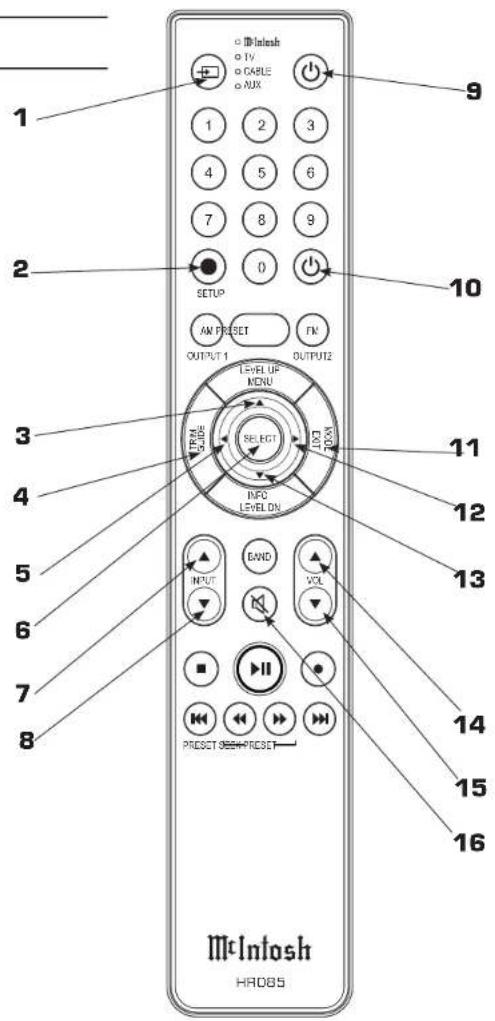
Additional Discrete Commands
Additional discrete commands for external control systems are available:
OPT1, OPT2, COAX1, COAX2, HDMI1, HDMI2, HDMI3, HDMI4, HDMI TV and Power (Cycle)
These additional commands can be accessed using an optional McIntosh HR093 Service Remote Control. A list of these commands as well as Pronto Hex Codes can be found in the MX100 Pronto Hex Codes document located in the Download section of the MX100 product information at mcintoshlabs.com. You can also contact McIntosh Technical Assistance or your dealer for more information.
Remote Control Batteries
The Remote Control, part number HR085, included with the MX100 is powered by two AAA batteries. To insert or remove batteries, open the battery compartment by removing the cover located on the back of the Remote Control. To open, pull the clasp located just above the opening downward.

Audyssey®
Audyssey is an intelligent system which will fine-tune your system to properly interact with the room's acoustics through precise calibration. This will get the highest possible performance from your complete system providing a tighter and more detailed sound with increased imaging.
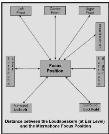
Audyssey Setup uses multiple measurement locations in the listening room to achieve the best possible acoustical results. The Focus Position or Main Listening Position is typically where one would be during serious viewing/listening.
flowchart
graph TD
    A["Left Front"] --> B["Focus Position"]
    C["Center Front"] --> B
    D["Right Front"] --> B
    E["Subwoofer"] --> B
    F["Surround Back Left"] --> B
    G["Surround Back Right"] --> B
    H["Left Front"] --> B
    I["Center Front"] --> B
    J["Right Front"] --> B
    K["Subwoofer"] --> B
    L["Surround Back Left"] --> B
    M["Surround Back Right"] --> B
    N["Left Front"] --> B
    O["Center Front"] --> B
    P["Right Front"] --> B
    Q["Subwoofer"] --> B
    R["Surround Back Left"] --> B
    S["Surround Back Right"] --> B
Figure 19- Audyssey® main listening position
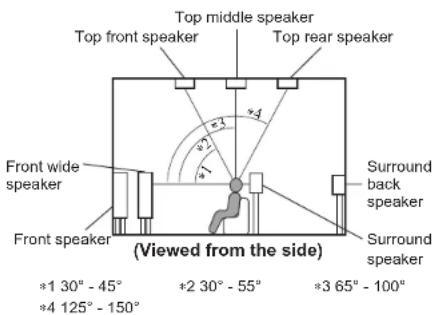
Figure 20- Speaker angles
Before proceeding with Audyssey Auto Setup, it is very important to first go into the Amp Assign submenu of Setup to establish the correct settings for your specific Loudspeaker complement and location in the Home Theater Room. The Audyssey submenu has a button for the Amp Assign submenu so you can confirm your settings. This will not only assure the best acoustic performance using Audyssey Room Equalization Correction, but it will also assure the best sonic performance using the latest in surround sound technology built into the MX100. The acoustic characteristics of the connected speakers and listening room are measured and the optimum settings are made automatically.
Audyssey Procedure Overview
- Complete Amp Assign (see “Amp Assign” on page 18)
- Connect assembled Microphone (see Figure 21)
-
Place Microphone in the Focus Position (see Figure 19)
-
Begin Test (adjust volume)
- Move Microphone to next position
- Continue, repeat with new positions
- When complete, select Complete

Figure 21- Microphone stand with Microphone
Audyssey Setup
Assemble the supplied setup microphone and stand (see Figure 21) then place it in the Main Listening Position or Focus Position. (See Figure 19) For best results:
- Make the room as quiet as possible. Background noise can disrupt the room measurements. Close windows and turn off the power on electronic devices (radios, air conditioners, fluorescent lights, etc.). The measurements could be affected by the sounds emitted by such devices
- During the measurement process, place cell phones outside the listening room. Cell phone signals could disrupt the measurements
- Do not stand between the speakers and Sound calibration microphone or allow obstacles in the path while the measurements are being made. Also, install the Sound calibration microphone

Figure 22- Audyssey Setup Microphone Jack
at least 20 inches (50cm) away from the wall. Failure to do so will result in inaccurate readings
- During the measurement process, audible test tones will come from the speakers and subwoofer(s), but this is part of normal operation. If there is background noise in the room, these test signals will increase in volume
- Operating VOLUME on the Remote Control unit or VOLUME on the main unit during the measurements will cancel the measurements
Begin Audyssey
With your speakers properly defined in Amp Assign and the Microphone set up and in the Focus position:
- Go to the Audyssey menu in the MX100 Browser interface Setup>Audyssey. Select "Next" (see Figure 23)
- Set the MX100 volume for approximately 50% (-6.5 dB). This setting can be adjusted for your circumstances upon subsequent tests. You can always abort a test and begin again. If the volume is set too low, your speakers will show as Not Detected after the test. If you heard a tone from the speakers during the test
but the speakers were not detected, turn the Right (VOLUME) Knob up (clockwise) and repeat the test using the Repeat Test button.
- Select "Begin Test" (see Figure 24)
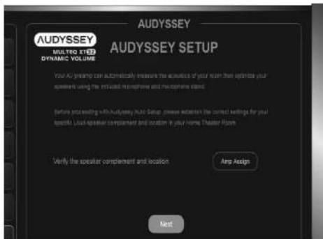
Figure 23- Audyssey Setup intro

Figure 24 Audyssey Setup Begin
- A test tone will be sent to all channels, one at a time to identify the channels making up your system.
- When the detected speakers are displayed, select "Next Step". This will start the Measurement Process. A special audio test signal will be sent to all previously detected channels, one at a time
- Leave the Microphone in the Focus Position for Calibration Position 0 (---). Select "Continue" (see Figure 25)

Figure 25— Audyssey Setup position 0
- After the series of tones end and the word "calibrating" disappears, move the Microphone to a new Calibration position no more than two feet (60cm) from the previous position. Select "Continue"
- Repeat the above step until completing between three and a maximum of six Calibration positions. Press “Complete” when you are done testing
- On the next screen select "Continue" to analyze the data (see Figure 26)


Figure 26- Audyssey measurements complete
- When data is 100% analysed, select "Next"
- The next two screens will report on your speaker sizes (either large or small). For more information about Speaker Size see “” on page 19. Select “Next” to leave these screens. (The second screen may not have speaker information depending on the number of speakers in your system)
- Next two pages show any adjustments to Speaker Level Trims. Values used to equalize speaker settings will be listed
- Next two pages concerns any adjustments to delay differentials for speakers. Audyssey will calculate needed timing corrections. The screen will display relative Speaker Distances in meters. Relative Speaker Distances are used to determine timing corrections.
- Select "Save" on the next screen (Figure 27) to keep the new Audyssey setup. Selecting "Abort" will discard the settings. Select "repeat" to discard and re-run Audyssey setup

Figure 27- Saving Audyssey calibration
Note: Do not change the speaker connections or subwoofer volume after Audyssey ^3 Setup. If these are changed, run Audyssey ^4 Setup again in order to configure the optimum equalizer settings.
Error Messages
An error message is displayed if Audyssey Setup could not be completed due to speaker placement, the measurement environment, etc. If an error message is displayed, check the relevant items and perform the necessary measures. Be sure to turn off the power before checking speaker connections. See "Figure 28—Audyssey error table" on page 27.
An error message is displayed if Audyssey ^® Setup could not be completed due to speaker placement, the measurement environment, etc. If an error message is displayed, check the relevant items and perform the necessary measures. (See Figure 28)
Be sure to turn off the power before checking speaker connections.
| Examples Error Details Corrective Measures | ||
| Speaker not detected Sound calibration microphone is not detectedNot all speakers could be detected | Connect the included Sound Calibration Microphone to the SETUP MIC jack on the Rear PanelCheck the speaker connectionsUse Test Tones in Speaker Menu to confirm speaker setup | |
| Noise high There is too much noise in the roomSpeaker or subwoofer sound is too low | Either turn off any device generating noise or move it awayPerform again when the surroundings are quieterCheck the speaker installation and the direction in which the speakers are facingAdjust the subwoofer's volume | |
Figure 28- Audyssey error table

The Trim Menu
The Trim Menu allows you to make and store adjustments to the to various settings. The following table lists the Trim option and the range of values that can be adjusted:
| Setting Values | |
| Bass -12dB to +12 dB in 1 dB increments | |
| Treble -12dB to +12 dB in 1 dB increments | |
| Audyssey MEQ On or Off | |
| Audyssey Dyn EQ | On or Off |
| Audyssey Dyn Vol | On or Off |
| Audio Delay (Lip Sync) | 0 to 500 ms in 25 ms increments |
| Trim Center -10dB to +10dB in 1 dB increments | |
| Trim Surrounds -10dB to +10dB in 1 dB increments | |
| Trim Heights -10dB to +10dB in 1 dB increments | |
| Trim Subwoofer -10dB to +10dB in 1 dB increments | |
| Meter Lights On or Off | |
| Display Brightness | Max, 75%, 50%, or 25% |
| Mode Music | Movie Games Auto Through |
The Trim menu can be entered using the Left Knob or the Remote Control.
Trim Menu Using the Remote Control
See Figure 29 for Remote Control buttons used for the Trim menu.
Enter the Trim Menu by pressing the Trim button (A) located to the left of the silver ring towards the center of the HR085 remote Control.
You can scroll through the Trim options by pressing the Trim Button (A) or by pressing the Up Arrow (B) or Down Arrow (C) on the silver ring.
Use the Left Arrow (D) and Right Arrow (E) on the silver ring to change values for the selected Trim option.
Use the Mode/Exit button (F) to exit the Trim Menu or wait ten seconds for the menu to close automatically.
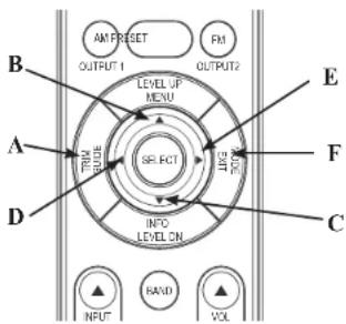
Figure 29 Remote Control Trim buttons
Trim Menu Using Knobs
To enter the Trim Menu, press and release the Left Knob. (Holding the knob for two seconds enters the Setup Menu instead of the Trim Menu.)
Scroll through the options by turning the Left knob.
Change the values of the current option by rotating the Right Knob. Turn the Left Knob to select another option to edit or press the Left Knob and release to exit the menu.
Changes will be saved.
More on Trim Settings
Most Trim settings are saved per Input. For these settings, changes to one Input will not affect another Input. The following Trim Inputs are saved by individual Input:
- Bass
- Treble
- Audio Delay
- Trim Center
- Trim Surrounds
- Trim Subwoofer
- Mode
Some Trim settings are saved Globally. Making a change to these settings for any Input will make the same change for ALL Inputs. Global Trim settings are:
• Audyssey MEQ
• Audyssey Dyn Vol (Dynamic Volume)
• Audyssey Dyn EQ
- Meter Lights
- Display Brightness
Mode
A Surround Mode can be set for each Input using the Trim Menu.
From the Mode submenu the following options are available:
• AUTO
• MOVIE
• MUSIC
• GAME
- THROUGH
MOVIE, MUSIC and GAME are variables that are assigned a specific Surround Mode choice. The Surround Modes that are used for MOVIE, MUSIC and GAME options are assigned in Setup. The default for each option is AUTO. Other options are Dolby Surround, DTS Neural:X:X, Multi-Channel Stereo, Stereo and Through. For more information about these options see "Surround Mode" on page 14.
To assign a mode to an Input:
- Press and Release the Left Knob (or press and release the TRIM GUIDE button on the Remote Control)
- Rotate the Left Knob until MODE is displayed (or press the Down Arrow on the silver ring of the Remote Control)
- Press and release the Left Knob (Press and release the SELECT button)
- Rotate the Left Knob until the desired Input is displayed (Use the Up or Down arrows to find the desired Input)
- Rotate the Right Knob scroll through the Surround Modes (use the Left and Right Arrows to scroll the Surround Modes)
- Press and Hold the Left Knob for two seconds to leave the Trim menu or Rotate the Left
Knob for another Input to assign a Surround Mode (press the MODE/EXIT button twice to leave the Trim Menu or wait until it times-out)
A quick way to change the current Input's Surround Mode is to use the MODE button on the outer ring of the Remote Control. Pressing the MODE button will cycle through the Surround Modes. Stop on your choice. The Display will time-out in a few seconds and your choice will be saved.
Supported HDMI Signals
The MX100 supports the HDCP copyright protection system. For proper playback the connected video device must also support HDCP. Here are supported video signals:
• 480i
· 480p
• 576i
• 576p
- 720p 60/50Hz
- 1080i 60/50Hz
• 1080p 60/50/24Hz
• 4K 60/50/30/25/24Hz
The MX100 can play the following audio formats via HDMI:
| 2-channel Linear PCM | 2-channel, 32 kHz – 192 kHz, 16/20/24 bit |
| Multi-channel Linear PCM | 7.1-channel, 32 kHz – 192 kHz, 16/20/24 bit |
| Bitstream Dolby D | gital / DTS / Dolby Atmos / Dolby TrueID /Dolby Digital Plus / DTS:X / DTS-HD Master Audio /DTS-HD High Resolution Audio / DTS Express |

Packing the MX100
When shipping the MX100, it is highly recommended that the unit be packed as it was originally shipped to avoid damage. Failure to properly pack the unit will likely result in damage. (The front panel is made of glass!) If you need any of the packing material, you can contact McIntosh Customer Service. Use only packing material that is in good condition and replace any material that has seen better days.
It is very important that the four plastic feet are attached to the bottom of the equipment. This will ensure the proper equipment location on the bottom pad. Failure to do this will result in shipping damage.
Quantity Part Number Description
1 034668 Shipping carton only
2 034669 End cap
1 033836 Inside carton only
2 033725 Top or filler pad
1 034576 Bottom pad
2 034446 Foam plug
4 017937 Plastic foot
4 400159 #10-32 x 3/4" screw
4 404080 #10 Flat washer
1 034667 Accessory Box
2 034500 Slotted foam
1 034501 Divider foam

Figure 30- Re-packing diagram
Audio Specifications
Unless otherwise noted, the below MX100 Specifications where taken with Audyssey® bypassed.
Frequency Response
±0.5dB from 20Hz-20,000Hz
Total Harmonic Distortion
0.005% maximum from 20Hz to 20,000Hz at rated Output
Signal To Noise Ratio
High Level: 96dB below rated output (A-Weighted)
Rated Output Voltage
5V Balanced Outputs
Output Impedance
330 Ohms
Coaxial/Optical Digital Input Rate and Formats
32kHz to 192kHz, 24-Bit PCM, Multichannel PCM, Dolby Digital, DTS
HDMI Input Rate and Formats
32kHz to 192kHz, 24-Bit PCM, Dolby Atmos, DTS
Room Correction
Audyssey MultEQ XT32 with Dynamic Volume and Dynamic EQ
Video Specifications
HDMI (Inputs and Outputs)
Version 2.0, High Dynamic Range (HDR), Dolby Vision, HDR10, HLG, 18Gbps 4K Ultra HD@50/60Hz, 4:4:4 Color, Rec. 2020, 3D Video pass-through
HDCP
Version 2.2
General Specifications
Power Requirements
Field AC Voltage conversion of the MX100 is not possible. The MX100 is factory configured for one of the following AC Voltages:
100 Volts, 50/60Hz at 30 watts
110 Volts, 50/60Hz at 30 watts
120 Volts, 50/60Hz at 30 watts
127 Volts, 50/60Hz at 30 watts
220 Volts, 50/60Hz at 30 watts
230 Volts, 50/60Hz at 30 watts
240 Volts, 50/60Hz at 30 watts
Standby, less than 0.5 watt
Note: Refer to the rear panel of the MX100 for the correct voltage.
Overall Dimensions
Width is 17-1/2 inches (44.5cm)
Width with Side Mount Brackets 19 inches (48.3cm)
Height is 4-15/16 inches (12.5cm) including feet
Depth is 21 inches (53.3cm) including the Front
Panel, Knobs, Rear Panel Connections and USB
Drive
Weight
17 pounds (7.7 kg) net, 39.5 pounds (18 kg) in shipping carton
Shipping Carton Dimensions
Width is 26-1/2 inches (67.3cm)
Depth is 17 inches (43.2cm)
Height is 24-1/4 inches (61.6cm)
Remote Control
HR085

The continuous improvement of its products is the policy of McIntosh Laboratory Incorporated who reserve the right to improve design without notice.
Printed in the U.S.A.
McIntosh Part No. 24109802
- MX100
- Thank you from all of us at McIntosh
- Make a Note
- Table of Contents
- List of Figures
- Safety First
- Trademark and License Information
- What is in the box
- Where to put it
- Making the Cuts
- Rack Mounting
- The Front Panel
- The Left Knob (INPUT)
- The Right Knob (VOLUME)
- Connections on the Back
- The Inputs
- The Outputs
- Making Connections
- 10baseT LAN
- HDMI
- USB
- Microphone
- RS232
- Wired IR Inputs
- Setup>GENERAL>RCLock
- SETUP: RC LOCK ON
- Digital Inputs
- AC Power
- Balanced Audio Outputs
- Power Control (Trigger) Outputs
- Data Out
- Setup>SPEAKERS>Floor Layout
- Entering Setup
- Determining the IP Address
- Setup>Network>Information>IP Address
- Exiting Setup
- Navigating Setup with the Remote Control
- Setup from a Browser
- Audio Setup Menu
- Setup>Audio
- Subwoofer Level Adjust
- Bass Sync
- Audio Delay (Lip Sync)
- Volume Scale
- Volume Scale Linear/dB Level
- Volume Limit
- Surround Mode
- Auto
- Audyssey
- MultEQ menu options:
- Dynamic Volume
- Video Setup Menu
- Setup>Video
- Setup>Video>HDMI Setup>Pass Through
- Setup>HDMI Setup>CEC
- Notes about ARC and CEC
- Inputs Setup Menu
- Setup>Inputs
- Speakers- Setup Menu
- Speaker Configuration
- Setup>Speakers>Speaker Config
- Crossovers
- Setup>Speakers>Crossovers
- Bass Type
- Setup>Speakers>Bass Type
- Speaker Distances
- Setup>Speakers>Distances
- Test Tones & Levels
- Setup>Speakers>Test Tones & Levels
- Network Setup Menu
- Setup>Network
- General Setup Menu
- Setup>General
- The General Menu has Six submenus:
- Factory Reset
- It is highly recommended that your McIntosh dealer perform the update process since failure to properly install the firmware can leave the MX100 in an unusable state.
- To use the Front Panel interface to Save the Configuration:
- If you are using the Front Panel to Load a Configuration:
- Additional Discrete Commands
- Remote Control Batteries
- Audyssey®
- Audyssey Procedure Overview
- Audyssey Setup
- Begin Audyssey
- Error Messages
- The Trim Menu
- Trim Menu Using the Remote Control
- Trim Menu Using Knobs
- More on Trim Settings
- Mode
- Supported HDMI Signals
- Packing the MX100
- Audio Specifications
- Frequency Response
- Total Harmonic Distortion
- Signal To Noise Ratio
- Rated Output Voltage
- Output Impedance
- Coaxial/Optical Digital Input Rate and Formats
- HDMI Input Rate and Formats
- Room Correction
- Video Specifications
- HDMI (Inputs and Outputs)
- HDCP
- General Specifications
- Power Requirements
- Overall Dimensions
- Weight
- Shipping Carton Dimensions
- Remote Control
Brand : MCINTOSH
Model : MX100
Category : AV amplifier