ASGA30FUTD-B - Séparateur FUJITSU - Free user manual and instructions
Find the device manual for free ASGA30FUTD-B FUJITSU in PDF.

| Product Type | Split Air Conditioner Indoor Unit |
| Model Number | ASGA30FUTD-B |
| Brand | Fujitsu |
| Cooling Capacity | 30,000 BTU/h |
| Heating Capacity | 30,000 BTU/h |
| Power Supply | 220-240 V, 50 Hz, 1 Phase |
| Dimensions (W x H x D) | 1000 x 300 x 250 mm |
| Net Weight | 15 kg |
| Refrigerant Type | R410A |
| Air Flow Rate (Max) | 1200 m³/h |
| Noise Level (Indoor) | 42 dB(A) |
| Energy Efficiency Ratio (EER) | 3.2 W/W |
| Operation Modes | Cooling, Heating, Fan, Dehumidification |
| Filter Type | Washable, Antibacterial |
| Remote Control | Included |
| Installation | Wall-mounted, professional installation recommended |
| Maintenance | Clean filter every 2 weeks; professional service annually |
| Safety Features | Overheat protection, auto restart, child lock |
| Spare Parts Availability | Service centers worldwide; filters, remote, PCB available |
| Warranty | 2 years parts and labor |
Frequently Asked Questions - ASGA30FUTD-B FUJITSU
User questions about ASGA30FUTD-B FUJITSU
0 question about this device. Answer the ones you know or ask your own.
Ask a new question about this device
Download the instructions for your Séparateur in PDF format for free! Find your manual ASGA30FUTD-B - FUJITSU and take your electronic device back in hand. On this page are published all the documents necessary for the use of your device. ASGA30FUTD-B by FUJITSU.
USER MANUAL ASGA30FUTD-B FUJITSU
INDOOR UNIT (Wall Mounted Type)
natural_image
Line drawing of a two-tiered air conditioner unit (no text or symbols)For authorized service personnel only.
Refer to the rating label with the serial number.
Note: This manual describes how to install the air conditioner described above. Handling and installation shall only be done by professionals as outlined in this manual.
1. SAFETY PRECAUTIONS
- Be sure to read this manual thoroughly before installation.
- The warnings and precautions indicated in this manual contain important information pertaining to your safety. Be sure to observe them.
- Hand this manual, together with the operating manual, to the customer. Request the customer to keep them on hand for future use, such as for relocating or repairing the product.
| WARNING | Indicates a potentially or imminently hazardous situation which, if not avoided, could result in death or serious injury. |
| Installation of this product must be done by experienced service technicians or professional installers only in accordance with this manual. Installation by nonprofessional or improper installation of the product may cause serious accidents such as injury, water leakage, electric shock, or fire. If the product is installed in disregard of the instructions in this Manual, it will void the manufacturer's warranty. | |
| Do not turn on the power until all work has been completed. Turning on the power before the work is completed can cause serious accidents such as electric shock or fire. | |
| If refrigerant leaks when you are working, ventilate the area. If the leaking refrigerant is exposed to a direct flame, it may produce a toxic gas. | |
| Do not use this equipment with air or any other unspecified refrigerant in the refrigerant lines. Excess pressure can cause a rupture. | |
| Installation must be performed in accordance with regulations, codes, or standards for electrical wiring and equipment in each country, region, or the installing place. | |
| Do not touch the fins of the heat exchanger. Touching the heat result in damage to the fins or personal injury such as skin rupture. | |
| This appliance is not intended for use by persons (including children) with reduced physical, sensory or mental capabilities, or lack of experience and knowledge, unless they have been given supervision or instruction concerning use of the appliance by a person responsible for their safety. Children should be supervised to ensure that they do not play with the appliance. | |
| CAUTION | Indicates a potentially hazardous situation that may result in minor or moderate injury or damage to property. |
| Read carefully all safety information written in this manual before you install or use the air conditioner. | |
| Install the product by following local codes and regulations in force at the place of installation, and the instructions provided by the manufacturer. | |
| This product is part of a set constituting an air conditioner. The product must not be installed alone or be installed with non-authorized device by the manufacturer. | |
| Always use a separate power supply line protected by a circuit breaker operating on all wires with a distance between contact of 3 mm for this product. | |
| To protect the persons, earth (ground) the product correctly, and use the power cable combined with an Earth Leakage Circuit Breaker (ELCB). | |
| The product is not explosion proof, and therefore should not be installed in explosive atmosphere. | |
| To avoid getting an electric shock, never touch the electrical components soon after the power supply has been turned off. After turning off the power, always wait 5 minutes or more before you touch the electrical components. | |
| This product contains no user-serviceable parts. Always consult experienced service technicians for repairing. | |
| When moving or relocating the air conditioner, consult experienced service technicians for disconnection and reinstallation of the product. | |
| Do not place any other electrical products or household belongings under the product. Condensation dripping from the product might get them wet, and may cause damage or malfunction of the property. | |
INSTALLATION MANUAL
[Barcode]
PART No. 9387082241
Contents
- SAFETY PRECAUTIONS 1
- ABOUT THIS PRODUCT......
- GENERAL SPECIFICATION 2
- SELECTING THE INSTALLATION LOCATION 3
- INSTALLATION WORK 3
- ELECTRICAL WIRING 5
- FINISHING....6
- FRONT PANEL REMOVAL AND INSTALLATION 7
- REMOTE CONTROLLER INSTALLATION....7
- OPTIONAL KIT INSTALLATION 8
- FUNCTION SETTING....8
- CHECK LIST....9
- TEST RUN....9
- CUSTOMER GUIDANCE 9
- ERROR CODES.... 10
2. ABOUT THIS PRODUCT
2.1. Precautions for using R410A refrigerant
| The basic installation work procedures are the same as conventional refrigerant (R22) models.However, pay careful attention to the following points: |
| Since the working pressure is 1.6 times higher than that of conventional refrigerant (R22) models, some of the piping and installation and service tools are special. (See the table below.)Especially, when replacing a conventional refrigerant (R22) model with a new refrigerant R410A model, always replace the conventional piping and flare nuts with the R410A piping and flare nuts. |
| Models that use refrigerant R410A have a different charging port thread diameter to prevent erroneous charging with conventional refrigerant (R22) and for safety. Therefore, check beforehand. [The charging port thread diameter for R410A is 1/2-20 UNF] |
| Be more careful that foreign matter (oil, water, etc.) does not enter the piping than with refrigerant (R22) models. Also, when storing the piping ,securely seal the opening by pinching, taping, etc. |
| When charging the refrigerant, take into account the slight change in the composition of the gas and liquid phases. And always charge from the liquid phase where refrigerant composition is stable. |
exchange for could 2.2. Special tools for R410A refrigerant
| Tool name Changes | |
| Gauge manifold | Pressure is high and cannot be measured with a conventional (R22) gauge. To prevent erroneous mixing of other refrigerants, the diameter of each port has been changed.It is recommended to use the gauge with seals-0.1 to 5.3 MPa (-1 to 53 bar) for high pressure.-0.1 to 3.8 MPa (-1 to 38 bar) for low pressure. |
| Charge hose | To increase pressure resistance, the hose material and base size were changed. |
| Vacuum pump | A conventional vacuum pump can be used by installing a vacuum pump adapter. |
| Gas leakage detector | Special gas leakage detector for HFC refrigerant R410A. |
Copper pipes
It is necessary to use seamless copper pipes and it is desirable that the amount of residual oil is less than 40 mg/10 m. Do not use copper pipes having a collapsed, deformed or discoloured portion (especially on the interior surface). Otherwise, the expansion value or capillary tube may become blocked with contaminants.
As an air conditioner using R410A incurs pressure higher than when using R22, it is necessary to choose adequate materials.
CONNECTION PIPE REQUIREMENT
WARNING
Do not use the existing (for R22) piping and flare nuts.
If the existing materials are used, the pressure inside the refrigerant cycle will rise and cause failure, injury, etc. (Use the special R410A materials.)
When installing and relocating the air conditioner, do not mix gases other than the specified refrigerant (R410A) to enter the refrigerant cycle.
If air or other gas enters the refrigerant cycle, the pressure inside the cycle will rise to an abnormally high value and cause failure, injury, etc.
2.3. Accessories
The following installation accessories are supplied. Use them as required.
| Name and Shape Q'ty Name and Shape Q'ty | |||||
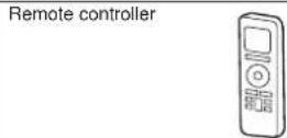
| Operating Manual |  | 1 | Remote controller holder |  | 1 |
| Installation Manual |  | 2 | Insulation (Drain hose)  | 1 | |
| Specification Manual |  | 1 | Cloth tape  | 1 | |
Wall hook bracket  | 1 | Tapping screw (large) 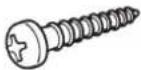 | 8 | ||
 | 1 | Tapping screw (small)  | 2 | ||
Battery  | 2 | ||||
2.4. Optional parts
Refer to each installation manual for the method of installing optional parts.
| Parts name Model No. | Application | |
| Wired Remote Controller* UTY-RNN*M For air conditioner operation | ||
| Apple-catechin filter UTR-FA13-1 | ||
| Ion deodorization filter UTR-FA13-2 | ||
| External connect kit* UTY-XWZXZ5 | For control input/output port | |
| Communication kit UTY-XCBXZ3 | For the installation of optional parts | |
^a Optional communication kit is necessary for the installation.
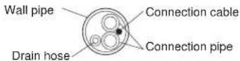
2.5. Additional materials required for installation
The following items are necessary to install this air conditioner. (The items are not included with the air conditioner and must be purchased separately.)
| Name | |
| Connection pipe assembly Saddle | |
| Connection cable | Drain hose |
| Wall pipe | Tapping screws |
| Decorative tape | Sealant |
| Vinyl tape | M10 bolt, nut |
| Wall cap | |
3. GENERAL SPECIFICATION
This Installation manual briefly outlines where and how to install the air conditioning system. Please read over the entire set of instructions for the indoor and outdoor units and make sure all accessory parts listed are with the system before beginning.
3.1. Type of copper pipe and insulation material
CAUTION
Refer to the installation manual for the outdoor unit for description of allowable pipe length and height difference.
| Diameter | ||
| Liquid pipe | Gas pipe | |
| 30/36 type 9.52 | mm (3/8 in.) 15.88 mm (5/8 in.) | |
| 18/24 type 6.35 | mm (1/4 in.) 15.88 mm (5/8 in.) | |
CAUTION
Install heat insulation around both the gas and liquid pipes. Failure to do so may cause water leaks.
Use heat insulation with heat resistance above 120 °C. Reverse cycle model only In addition, if the humidity level at the installation location of the refrigerant piping is expected to exceed 70%, install heat insulation around the refrigerant piping. If the expected humidity level is 70-80%, use heat insulation that is 15 mm or thicker and if the expected humidity exceeds 80%, use heat insulation that is 20 mm or thicker. If heat insulation is used that is not as thick as specified, condensation may form on the surface of the insulation. In addition, use heat insulation with heat conductivity of 0.045 W/(m·K) or less (at 20 °C).
3.2. Electrical requirement
The indoor unit is powered from the outdoor unit or branch box. Do not power indoor unit from separate power source.
WARNING
Refer to local codes for acceptable cable type.
| Cable | Cable size (mm ^2 ) | Type | Remarks |
| Connection cable | 1.5 ~ 2.5 | Type 60245 IEC 57 | *Refer to “Outdoor unit installation manual” |
Max. Cable Length: Limit voltage drop to less than 2%. Increase cable gauge if voltage drop is 2% or more.
- Before starting work check that power is not being supplied to all poles of the indoor unit and outdoor unit.
• Install all electrical works in accordance to standard. - Install the disconnect device with a contact gap of at least 3mm in all poles nearby the units. (Both indoor unit and outdoor unit)
- Wiring size must comply with the applicable local and national code.
4. SELECTING THE INSTALLATION LOCATION
Decide the mounting position with the customer as follows:

WARNING
Select installation locations that can properly support the weight of the indoor unit and which will not amplify sound or vibration. If the installation location is not strong enough, the indoor unit may fall and cause injuries.
Install the units securely so that they do not topple or fall.

CAUTION
Do not install the unit in the following areas:
- Area with high salt content, such as at the seaside. It will deteriorate metal parts, causing the parts to fail or the unit to leak water.
- Area filled with mineral oil or containing a large amount of splashed oil or steam, such as a kitchen.
It will deteriorate plastic parts, causing the parts to fail or the unit to leak water. - Area that generates substances that adversely affect the equipment, such as sulphuric gas, chlorine gas, acid, or alkali.
It will cause the copper pipes and brazed joints to corrode, which can cause refrigerant leakage. - Area that can cause combustible gas to leak, contains suspended carbon fibres or flammable dust, or volatile inflammables such as paint thinner or gasoline. If gas leaks and settles around the unit, it can cause a fire.
- Area where animals may urinate on the unit or ammonia may be generated.
Do not use the unit for special purposes, such as storing food, raising animals, growing plants, or preserving precision devices or art objects. It can degrade the quality of the preserved or stored objects.
Do not install where there is the danger of combustible gas leakage.
Do not install the unit near a source of heat, steam, or flammable gas.
Install the unit where drainage does not cause any trouble.
Install the unit where ambient temperature does not reach 60^ C or more. Take a measure such as ventilation for an environment in which heat is retained.
If children under 10 years old may approach the unit, take preventive measures so that they cannot reach the unit.
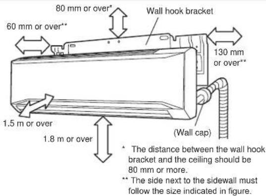
Install the indoor unit on the wall where the height from the floors more than 1.8 m.
(1) Install the indoor unit level on a strong wall which is not subject to vibration.
(2) The inlet and outlet ports should not be obstructed: the air should be able to blow all over the room.
(3) Install the unit at a place near an power outlet or special branch circuit.
(4) Do not install the unit where it will be exposed to direct sunlight.
(5) Install the unit where connection to the outdoor unit is easy
(6) Install the unit where the drain pipe can be easily installed.
(7) Take servicing, etc. into consideration and leave the spaces shown in "5.1. Installation dimensions". Also install the unit where the filter can be removed.
Correct initial installation location is important because it is difficult to move unit after it is installed.
5. INSTALLATION WORK
5.1. Installation dimensions
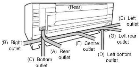
5.2. Indoor unit piping direction
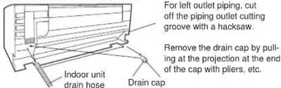
The piping can be connected in the 7 directions in the figure. When the piping is connected in direction (B), (C), (D) or (E), cut along the piping groove in the side of the front panel with a hacksaw.
5.3. Cutting the hole in the wall for the connecting pipes
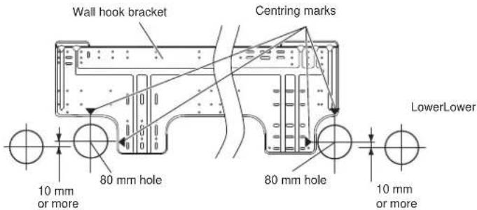
(1) Cut a 80 mm diameter hole in the wall at the position shown in the figure.
(2) When cutting the wall hole at the inside of the wall hook bracket, cut the hole to a point of intersection of centre marks.
When cutting the wall hole at the outside of the wall hook bracket, cut the hole at a point of 10 mm below.
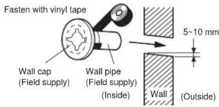
(3) Cut the hole so that the outside end is lower (5 to 10 mm) than the inside end.
(4) Always align the centre of the wall hole. If misaligned, water leakage will occur.
(5) Cut the wall pipe to match the wall thickness, stick it into the wall cap, fasten the cap with vinyl tape, and stick the pipe through the hole.
(6) For left piping and right piping, cut the hole a little lower so that drain water will flow freely.

WARNING
If the wall pipe is not used, the cable interconnecting the indoor unit(s) and outdoor unit or branch box may touch metal and cause electric discharge.
5.4. Installing the wall hook bracket
(1) Install the wall hook bracket so that it is correctly positioned horizontally and vertically. If the wall hook bracket is tiled, water will drip to the floor.
(2) Install the wall hook bracket so that it is strong enough to support the weight of the unit.
- Fasten the wall hook bracket to the wall with 6 or more screws through the holes near the outer edge of the bracket.
- Check that there is no rattle at the wall hook bracket.
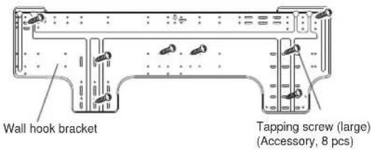

CAUTION
Install the wall hook bracket by levelling, both horizontally and vertically.
5.5. Forming the drain hose and pipe

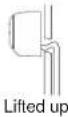
CAUTION
Insert drain hose and drain cap securely. Drain should slope down to avoid water leakage.
When inserting the drain hose, no other material than water should be applied. Application of other material will cause deterioration of the hose, and may cause water leakage.
When you remove the drain hose, be sure to attach the drain cap.
When you secure the piping and drain hose with tape, arrange the drain hose so that it is placed under the piping.
For drain hose piping in low temperature environment, you need to apply protection to prevent a frozen drain hose.
In low temperature environment (when outdoor temperature is under 0 °C), water in the drain hose could be frozen after cooling operation. Frozen drain water will block the water flow in the hose, and may cause water leakage at the indoor unit.
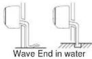
[Rear piping, Right piping, Bottom piping]
• Install the indoor unit piping in the direction of the wall hole and bind the drain hose and pipe together with vinyl tape.
• Install the piping so that the drain hose is at the bottom.
- Wrap the pipes of the indoor unit that are visible from the outside with decorative tape.
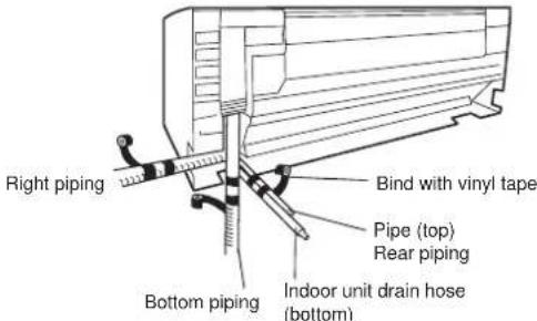
[For Left rear piping, Left piping]
Interchange the drain cap and the drain hose.
![FUJITSU ASGA30FUTD-B - [For Left rear piping, Left piping] - 2](/content/2026/05/826173/images/4e8c9626129a329784225941bc788c222f8a8f057ecb11677af73278435403b0.jpg)
CAUTION
Insert the drain hose and drain cap into the drain port, making sure that it comes in contact with the back of the drain port, and then mount it. If the drain hose is not connected properly, leaking will occur.
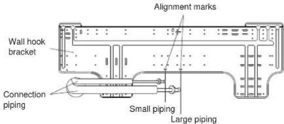
- For left piping and left rear piping, align the marks on the wall hook bracket and shape the connection pipe.
- Bend the connection piping at the bend radius of 100 mm or more and install no more than 35 mm from the wall.
• After passing the indoor piping and drain hose through the wall hole, hang the indoor unit on the hooks at the top and bottom of the wall hook bracket.
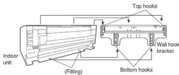
After hooking the indoor unit to the top hook, hook the fittings of the indoor unit to the 2 bottom hooks while lowering the unit and pushing it against the wall.
[Installing the indoor unit]
- Hang the indoor unit from the hooks at the top of the wall hook bracket.
- Insert the spacer, etc. between the indoor unit and the wall hook bracket and separate the bottom of the indoor unit from the wall.
![FUJITSU ASGA30FUTD-B - [Installing the indoor unit] - 1](/content/2026/05/826173/images/5e8cff267ef6adbc0ab72a73dfa376350f2f19e5a499ab6a61f6be046e9d17c9.jpg)
5.6. Pipe connection

WARNING
Tighten the flare nuts with a torque wrench using the specified tightening method. Otherwise, the flare nuts could break after a prolonged period, causing refrigerant to leak and generate hazardous gas if the refrigerant comes into contact with a flame.
5.6.1. Flaring
• Use special pipe cutter and flare tool exclusive for R410A.
(1) Cut the connection pipe to the necessary length with a pipe cutter.
(2) Hold the pipe downward so that cuttings will not enter the pipe and remove any burrs.
(3) Insert the flare nut (always use the flare nut attached to the indoor and outdoor units respectively) onto the pipe and perform the flare processing with a flare tool. Use the special R410A flare tool, or the conventional flare tool. Leakage of refrigerant may result if other flare nuts are used.
(4) Protect the pipes by pinching them or with tape to prevent dust, dirt, or water from entering the pipes.
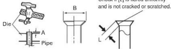
| Pipe outside diameter [mm (in.)] | Dimension A [mm] | Dimension B-84 [mm] |
| Flare tool for R410A, clutch type | ||
| 6.35 (1/4) | 0 to 0.5 | 9.1 |
| 9.52 (3/8) 13.2 | ||
| 15.88 (5/8) 19.7 |
When using conventional flare tools to flare R410A pipes, the dimension A should be approximately 0.5 mm more than indicated in the table (for flaring with R410A flare tools) to achieve the specified flaring. Use a thickness gauge to measure the dimension A.
Width across
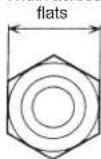
| Pipe outside diameter [mm (In.)] | Width across flats of Flare nut [mm] |
| 6.35 (1/4) 17 | |
| 9.52 (3/8) 22 | |
| 15.88 (5/8) 29 |
5.6.2. Bending pipes

CAUTION
To prevent breaking of the pipe, avoid sharp bends. Bend the pipe with a radius curvature of 150 mm or more.
If the pipe is bent repeatedly at the same place, it will break.
• If pipes are shaped by hand, be careful not to collapse them.
- Do not bend the pipes in an angle more than 90^ .
- When pipes are repeatedly bend or stretched, the material will harden, making it difficult to bend or stretch them any more.
- Do not bend or stretch the pipes more than 3 times.
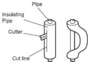
- When bending the pipe, do not bend it as is. The pipe will be collapsed. In this case, cut the insulating pipe with a sharp cutter as shown on the right, and bend it after exposing the pipe. After bending the pipe as you want, be sure to put the heat insulating pipe back on the pipe, and secure it with tape.
5.6.3. Pipe connection
| CAUTION |
| Be sure to Install the pipe against the port on the indoor unit correctly. If the centring is improper, the flare nut cannot tighten smoothly. If the flare nut is forced to turn, the threads will be damaged. |
| Do not remove the flare nut from the indoor unit pipe until immediately before connecting the connection pipe. |
| Hold the torque wrench at its grip, keeping it in the right angle with the pipe, in order to tighten the flare nut correctly. |
| Tighten the flare nuts with a torque wrench using the specified tightening method. Otherwise, the flare nuts could break after a prolonged period, causing refrigerant to leak and generate hazardous gas if the refrigerant comes into contact with a flame. |
| In order to prevent water from leaking into the control box, make sure that the piping is well insulated. |
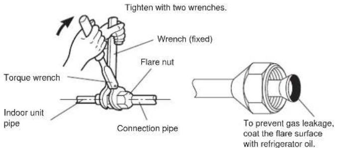
Flare nut tightening torque
| Flare nut Tightening torque | |
| 6.35 mm (1/4 in.) 16 to 18 N · m (160 to 180 kgf · cm) | |
| 9.52 mm (3/8 in.) 32 to 42 N · m (320 to 420 kgf · cm) | |
| 15.88 mm (5/8 in.) 63 to 75 N · m (630 to 750 kgf · cm) |
Do not remove the cap from the connection pipe before connecting the pipe.
6. ELECTRICAL WIRING
6.1. Wiring system diagram
| WARNING |
| Before connecting the wires, make sure the power supply is OFF. |
| Use a dedicated power supply circuit. Insufficient power capacity in the electrical circuit or improper wiring may cause electric shock or fire. |
| Install a breaker at the power supply. Improper breaker selection can cause electric shock or fire. |
| Install a leakage circuit breaker in accordance with the related laws and regulations. An improperly installed electrical box cover can cause serious accidents such as electric shock or fire through exposure to dust or water. |
| A circuit breaker is installed in the permanent wiring. Always use a circuit that can trip all the poles of the wiring and has an isolation distance of at least 3 mm between the contacts of each pole. |
| Use designated cables and power cables. Improper use may cause electric shock or fire by poor connection, insufficient insulation, or over current. |
| Do not modify power cable, use extension cable or branch wiring. Improper use may cause electric shock or fire by poor connection, insufficient insulation or over current. |
| Connect the connector cable securely to the terminal. Check no mechanical force bears on the cables connected to the terminals. Faulty installation can cause a fire. |
| Use round terminals and tighten the terminal screws to the specified torques, otherwise, abnormal overheating may be produced and possibly cause serious damage inside the unit. |
| Make sure to secure the insulation portion of the connector cable with the cable clamp. Damaged insulation can cause a short circuit. |
| Fix cables so that cables do not make contact with the pipes (especially on high pressure side). Do not make power supply cable and transmission cable come in contact with valves (Gas). |
| Never install a power factor improvement condenser. Instead of improving the power factor, the condenser may overheat. |
WARNING
| WARNING |
| Be sure to perform the earthing (grounding) work.Do not connect earthing (grounding) wires to a gas pipe, water pipe, lightning rod or earthing (grounding) wire for a telephone.Connection to a gas pipe may cause a fire or explosion if gas leaks.Connection to a water pipe is not an effective earthing (grounding) method if PVC pipe is used.Connection to the earthing (grounding) wire of a telephone or to a lightning rod may cause a dangerously abnormal rise in the electrical potential if lightning strikes.Improper earthing (grounding) work can cause electric shocks. |
| Securely install the electrical box cover on the unit. An improperly installed service panel can cause serious accidents such as electric shock or fire through exposure to dust or water. |
WARNING
| CAUTION |
| The primary power supply capacity is for the air conditioner itself, and does not include the concurrent use of other devices. |
| Do not start operation until the refrigerant is charged completely. The compressor will fail if it is operated before the refrigerant piping charging is complete. |
| Be sure not to remove thermistor sensor etc. from power wiring and connection wiring. Compressor may fail if operated while removed. |
| Start wiring work after closing branch switch and over current breaker. |
| When using an earth leakage breaker that has been designed solely for earth (ground) fault protection, be sure to install a fuse-equipped switch or circuit breaker. |
| Do not connect the AC power supply to the transmission line terminal board. Improper wiring can damage the entire system. |
| If the temperature surrounding the breaker is too high, the amperage at which the breaker cuts out may decrease. |
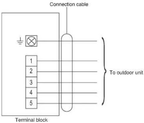
[Heat & Cool model (Reverse cycle)]
[Cooling model]
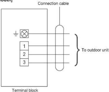
6.2. Indoor unit wiring
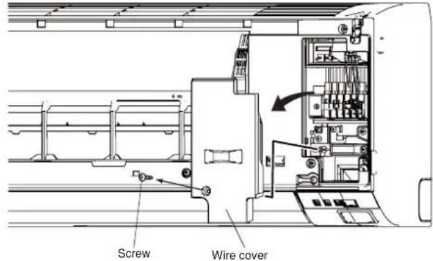
(1) Open the intake grille. Remove the tapping screw for the wire cover and remove the wire cover.
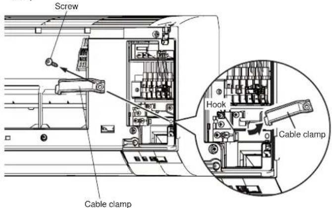
(2) Remove the tapping screw and while minding the cable clamp hook, remove the cable clamp.
(3) Connect the end of the connection cable fully into the terminal block.
[Heat & Cool model (Reverse cycle)]
[Cooling model]
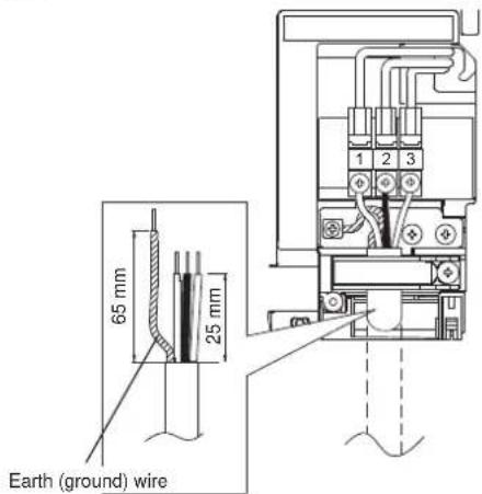
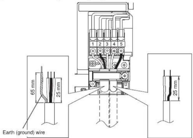
6.3. How to connect wiring to the terminals
Caution when wiring cable
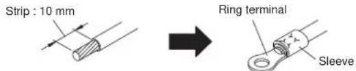
When stripping off the insulation of a lead wire, always use a special tool such as a wire stripper. If there is no special tool available, carefully strip the insulation with a knife etc.
(1) Use Ring terminals with insulating sleeves as shown in the figure below to connect to the terminal block.
(2) Securely clamp the Ring terminals to the wires using an appropriate tool so that the wires do not come loose.
(3) Use the specified wires, connect them securely, and fasten them so that there is no stress placed on the terminals.
(4) Use an appropriate screwdriver to tighten the terminal screws. Do not use a screwdriver that is too small, otherwise, the screw heads may be damaged and prevent the screws from being properly tightened.
(5) Do not tighten the terminal screws too much, otherwise, the screws may break.
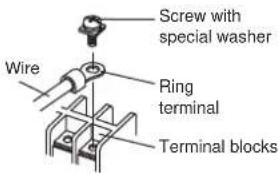
(6) See the table for the terminal screw tightening torques.
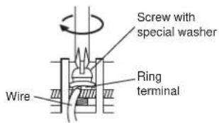
Tightening torque [N·m (kgf·cm)]
M4 screw 1.2 to 1.8 (12 to 18)
CAUTION
Match the terminal block numbers and connection cable colours with those of the outdoor unit or branch box. Erroneous wiring may cause burning of the electric parts.
Connect the connection cables firmly to the terminal block. Imperfect installation cause a fire.
Always fasten the outside covering of the connection cable with the cable clamp. (If the insulator is chafed, electric discharge may occur.)
Always connect the earth (ground) wire.
Do not use the earth (ground) screw of the indoor unit for the connection other than a specified outdoor unit or branch box.
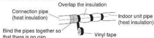
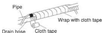
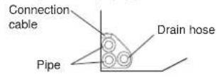
7. FINISHING
(1) Insulate between pipes. (Varies upon direction of the piping as shown in "5.2. Indoor unit piping direction")
• Insulate suction and discharge pipes separately.
For (A) Rear, (B) Right, and (C) Bottom piping:
- Overlap the connection pipe heat insulation and indoor unit pipe heat insulation and bind them with vinyl tape so that there is no gap.
For (D) Left bottom, (E) Left, (F) Centre and (G) Left rear piping:
- Butt the connection pipe heat insulation and indoor unit pipe heat insulation together and bind them with and vinyl tape so that there is no gap.
- Wrap the area which accommodates the rear piping housing section with cloth tape.
- Bind the connection cable to the top of the pipe with vinyl tape.
- Bundle the piping and drain hose together by wrapping them with cloth tape over the range within which they fit into the rear piping housing section.
(2) Temporarily fasten the connection cable along the connection pipe with vinyl tape. (Wrap to about 1/3 the width of the tape from the bottom of the pipe so that water does not enter.)
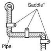
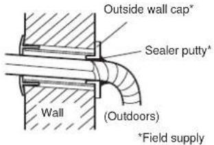
(3) Fasten the connection pipe to the outside wall with saddles, etc.
(4) Fill the gap between the outside wall pipe hole and the pipe with sealer so that rain water and wind cannot blow in.
(5) Fasten the drain hose to the outside wall, etc.
Example of left piping
Example of left rear piping
Check the following:
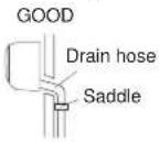
PROHIBITED PROHIBITED PROHIBITED
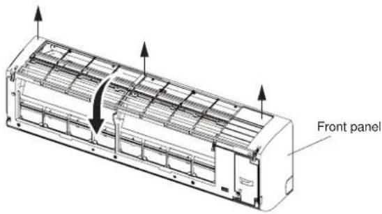
8. FRONT PANEL REMOVAL AND INSTALLATION
Intake grill removal Intake grill installation
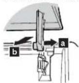
Open the intake grille. While gently pressing the left and right mounting shafts of the intake grille outward "a", remove the intake grille in direction of the arrow "b".
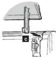
While holding the grille horizontal, set the left and right mounting shafts into the pillow blocks at the top of the panel "c".
To latch each shaft properly, insert the shaft until it snaps. Press 4 places on the intake grille to close it completely.
8.1. Front panel removal
(1) Remove intake grille (Reference the intake grille removal.)
(2) Remove 4 caps.
(3) Remove wire cover.
(4) Remove 10 screws.
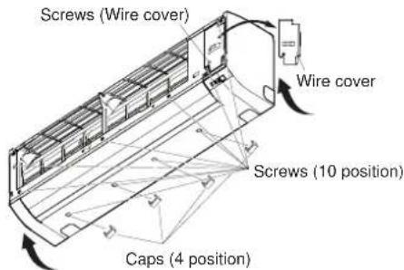
NOTE : When replacing the front panel, do not scratch or damage the louver.
(5) The front panel is pulled to the front, raising the upper surface, then the front panel is removed.
8.2. Front panel installation
(1) First, fit the lower part of the front panel, and insert top and middle hooks. (3 top sides, 5 middles)
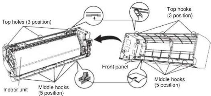
(2) Attach the 10 screws.
(3) Attach the wire cover.
(4) Attach the 4 caps.
(5) Attach the intake grille.
CAUTION
Install the front panel and INTAKE GRILLE securely. If installation is imperfect, the front panel or INTAKE GRILLE may fall off and cause injury.
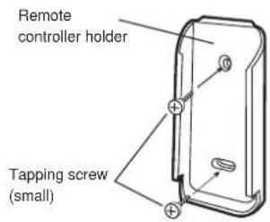
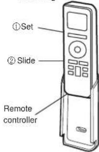
9. REMOTE CONTROLLER INSTALLATION
CAUTION
Check that the indoor unit correctly receives the signal from the remote controller, then install the remote controller holder.
Select the remote controller holder selection site by paying careful attention to the following:
Avoid places in direct sunlight.
Select a place that will not be affected by the heat from a stove, etc.
9.1. Remote controller holder installation
• Install the remote controller a maximum distance of 7 m from the remote control receiver. However, when installing the remote controller, check that it operates correctly.
• Install the remote controller holder to a wall, pillar, etc. with the tapping screw.
remote controller
holder fixing
remote controller
mounting
10. OPTIONAL KIT INSTALLATION
This air conditioner can be connected with the following optional kits.
Wired remote controller
- External connect kit
11. FUNCTION SETTING
Perform the "FUNCTION SETTING" according to the installation conditions using the remote controller.
CAUTION
Confirm whether the wiring work for Outdoor unit or Branch box has been finished.
Confirm that the cover for the electrical enclosure on the outdoor unit is in place.
- This procedure changes to the function settings used to control according to the installation conditions. Incorrect settings can cause the indoor unit to malfunction.
- After the power is turned on, perform the "FUNCTION SETTING" according to installation conditions using the remote controller.
- The settings may be selected between the following two: Function Number and Setting Value.
- Settings will not be changed if invalid numbers or setting values are selected.
- Refer to the installation manual enclosed with the remote controller when the wired remote controller (option) is used.
to the
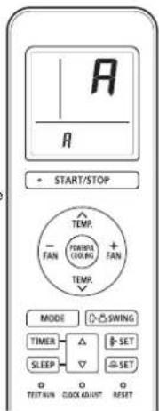
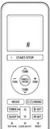
Entering the Function Setting Mode
While pressing the POWERFUL COOLING button and MODE button simultaneously, press the RESET button to enter the function setting mode.
STEP 1
Selecting the Remote Controller Custom Code
Use the following steps to select the custom code of the remote controller. (Note that the air conditioner cannot receive a signal if the air conditioner has not been set for the custom code.)
The custom codes that are set through this process are applicable only during the FUNCTION SETTING process. For details on how to set the custom codes through the normal process, refer to "Remote controller custom code setting".
(1) Press TEMP. (∧) (∨) buttons to change the custom code between A→B→C→D. Match the code on the display to the air conditioner custom code (initially set to A). (If the custom code does not need to be selected, press the MODE button and proceed to STEP 2.)
(2) Press the START/STOP button and check that the indoor unit can receive signals at the displayed custom code.
(3) Press the MODE button to accept the custom code, and proceed to STEP 2.
STEP 2
Selecting the Function Number and Setting Value
(1) Press the TEMP. (N) buttons to select the function number. (Press the FAN (-) button to switch between the left and right digits.)
(2) Press the FAN (+) button to proceed to setting the value. (Press the FAN (+) button again to return to the function number selection.)
(3) Press the TEMP. (∧) (√) buttons to select the setting value. (Press the FAN (-) button to switch between the left and right digits.)
(4) Press the START/STOP button, then the POWERFUL COOLING button, in order to fix the settings. the indoor unit
(5) Press the RESET button to end the function setting mode.
(6) After completing the FUNCTION SETTING, be sure to turn off the power and turn it on again.
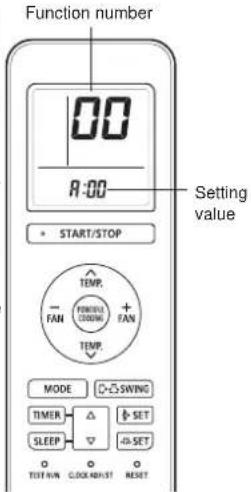
CAUTION
After turning off the power, wait 30 seconds or more before turning on it again.
The Function Setting does not become active unless the power is turned off then on again.
Room temperature sensor control for cooling
Depending on the installed environment, correction of the room temperature sensor may be required. Select the appropriate control setting according to the installed environment.
(◆ ... Factory setting)
| Function number Setting value | Setting description | |
| 30 | 00 Standard | |
| 01 Lower control | ||
Room temperature sensor control for heating
Depending on the installed environment, correction of the room temperature sensor may be required. Select the appropriate control setting according to the installed environment. (◆... Factory setting)
| Function number Setting value | Setting description | |
| 31 | 00 Standard | |
| 01 Lowest control | ||
| 02 Lower control | ||
| 03 | Low control | |
Auto restart
Enable or disable automatic restart after a power interruption.
(◆... Factory setting)
| Function number Setting value | Setting description | |
| 40 | 00 Enable | |
| 01 Disable | ||
* Auto restart is an emergency function such as for power outage etc. Do not attempt to use this function in normal operation. Be sure to operate the unit by remote controller or external device.
Room temperature sensor switching
(Only for wired remote controller)
When using the Wired remote controller temperature sensor, change the setting to "Both" (01).
(◆... Factory setting)
| Function number Setting value | Setting description | |
| 42 | 00 Indoor unit | |
| 01 Both | ||
00: Sensor on the indoor unit is active.
01: Sensors on both indoor unit and wired remote controller are active.
* Remote controller sensor must be turned on by using the remote controller
Remote controller custom code
(Only for wireless remote controller)
The indoor unit custom code can be changed.
Select the appropriate custom code.
(◆ ... Factory setting)
| Function number Setting value | Setting description | |
| 44 | 00 | A |
| 01 | B | |
| 02 | C | |
| 03 | D | |
Setting record
Record any changes to the settings in the following table.
| Function setting Setting Value | |
| Room temperature sensor control for cooling | |
| Room temperature sensor control for heating | |
| Auto restart | |
| Room temperature sensor switching | |
| Remote controller custom code |
After completing the Function Setting, be sure to turn off the power and turn it on again.
Remote controller custom code setting
When 2 or more air conditioners are installed in a room and the remote controller is operating an air conditioner other than the one you wish to set, change the custom code of the remote controller to operate only the air conditioner you wish to set (4 selections possible).
- Confirm the setting of the remote controller custom code and the function setting. If these do not match, the remote controller cannot be used to operate for the air conditioner.
Selecting the Remote Controller Custom Code
Use the following steps to select the custom code of the remote controller. (Note that the air conditioner cannot receive a signal if the air conditioner has not been set for the custom code.)
(1) Press the START/STOP button until only the clock is displayed on the remote controller display.
(2) Press the MODE button for at least 5 seconds to display the current custom code (initially set to A).
(3) Press SET TEMP. (A) ( ) buttons to change the custom code between A→B→C→D. Match the code on the display to the air conditioner custom code.
(4) Press the MODE button again to return to the clock display. The custom code will be changed.
If no buttons are pressed within 30 seconds after the custom code is displayed, the system returns to the original clock display. In this case, start again from step 1.
The air conditioner custom code is set to A prior to shipment.
The remote controller resets to custom code A when the batteries in the remote controller are replaced. If you use a custom code other than custom code A, reset the custom code after replacing the batteries.
If you do not know the air conditioner custom code setting, try each of the custom codes (A→B→C→D) until you find the code which operates the air conditioner.
12. CHECK LIST
Pay special attention to the check items below when installing the indoor unit(s). After installation is complete, be sure to check the following check items again.
| CHECK ITEMS CHECK BOX | |
| Has the indoor unit been installed correctly? | |
| Has there been a check for gas leaks (refrigerant pipes)? | |
| Has heat insulation work been completed? | |
| Does water drain easily from the indoor units? | |
| Are the wires and pipes all connected completely? | |
| Is the connection cable the specified thickness? | |
| Are the inlets and outlets free of any obstacles? | |
| After installation is completed, has the proper operation and handling been explained to the user? |
13. TEST RUN

WARNING
Do not turn on the power until all installation work is complete.

CAUTION
When restarting after a long period of disuse in the winter, turn the power switch on at least 12 hours before starting the unit.
Do not operate the air conditioner in test run for a long time.
[Operation method]
- For the operation method, refer to the operating manual.
- The outdoor unit may not operate depending on the room temperature. In this case, press the TEST RUN button on the remote controller while the air conditioner is running. (Point the transmitter section of the remote controller toward the air conditioner and press the TEST RUN button with the tip of a ballpoint pen, etc.)
- To end test operation, press the remote controller START/STOP button. (When the air conditioner is running by pressing the TEST RUN button, the OPERATION Lamp and TIMER Lamp will simultaneously flash slowly.)
[Using the wired remote control] (Option)
- For the operation method, refer to the operating manual.
(1) Stop the air conditioner operation.
(2) Press the master control button and the FAN control button simultaneously for 2 seconds or more to start the test run.
(3) Press the START/STOP button to stop the test run.
Transmitter section
![FUJITSU ASGA30FUTD-B - [Using the wired remote control] (Option) - 1](/content/2026/05/826173/images/7230079bbacdb6316a9328b1a4387b9b645665dc2f709f3bbb661da8114ff7e4.jpg)
natural_image
Line drawing of a hand holding a remote control with a pen, no text or symbols presentTEST RUN button
![FUJITSU ASGA30FUTD-B - [Using the wired remote control] (Option) - 2](/content/2026/05/826173/images/9d696b1895ed9f67d7ad7ca53cb3bbcace7f0f949a727a16644664e55a85c862.jpg)
![FUJITSU ASGA30FUTD-B - [Using the wired remote control] (Option) - 3](/content/2026/05/826173/images/cfabd1d37045d0bfce19f93b1bc70694aab6802d1da25c1c132773092ddc4b35.jpg)
Test run display
14. CUSTOMER GUIDANCE
Explain the following to the customer in accordance with the operating manual:
(1) Starting and stopping method, operation switching, temperature adjustment, timer, air flow switching, and other remote control unit operations.
(2) Air filter removal and cleaning, and how to use the air louvers.
(3) Give the operating manual to the customer.
(4) If the custom code is changed, explain to the customer how it changed (the system returns to custom code A when the batteries in the remote controller are replaced).
^* (4) is applicable to using wireless remote controller.
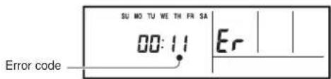
15. ERROR CODES
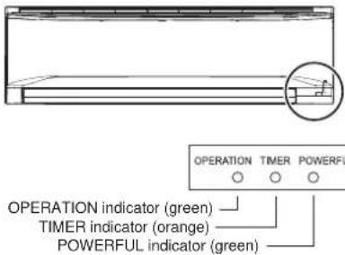
If you use a wireless remote controller, the lamp on the photo detector unit will output error codes by way of blinking patterns. If you use a wired remote controller, error codes will appear on the remote controller display. See the lamp blinking patterns and error codes in the table. An error display is displayed only during operation.
| Error display | Wired remote controller Error code | Description | ||
| OPERATION lamp (green) | TIMER lamp (orange) | POWERFUL lamp (green) | ||
| ●(1) | ●(1) | ◇ | 11 | Serial communication error |
| ●(1) | ●(2) | ◇ | 12 | Wired remote controller communication error |
| ●(1) | ●(5) | ◇ | 15 | Check run unfinished |
| ●(2) | ●(1) | ◇ | 21 | Unit number or Refrigerant circuit address setting error [Simultaneous Multi] |
| ●(2) | ●(2) | ◇ | 22 | Indoor unit capacity error |
| ●(2) | ●(3) | ◇ | 23 | Combination error |
| ●(2) | ●(4) | ◇ | 24 | • Connection unit number error (indoor slave unit) [Simultaneous Multi] • Connection unit number error (indoor unit or branch unit) [Flexible Multi] |
| ●(2) | ●(7) | ◇ | 27 | Master unit, slave unit set-up error [Simultaneous Multi] |
| ●(3) | ●(2) | ◇ | 32 | Indoor unit PCB model information error |
| ●(3) | ●(5) | ◇ | 35 | Manual auto switch error |
| ●(4) | ●(1) | ◇ | 41 | Room temp. sensor error |
| ●(4) | ●(2) | ◇ | 42 | Indoor unit Heat Ex. Middle temp. sensor error |
| ●(5) | ●(1) | ◇ | 51 | Indoor unit fan motor error |
| ●(5) | ●(3) | ◇ | 53 | Drain pump error |
| ●(5) | ●(7) | ◇ | 57 | Damper error |
| ●(5) | ●(15) | ◇ | 58 | Indoor unit error |
| ●(6) | ●(2) | ◇ | 62 | Outdoor unit main PCB model information error or communication error |
| ●(6) | ●(3) | ◇ | 63 | Inverter error |
| ●(6) | ●(4) | ◇ | 64 | Active filter error, PFC circuit error |
| ●(6) | ●(5) | ◇ | 65 | Trip terminal L error |
| ●(6) | ●(8) | ◇ | 68 | Outdoor unit rush current limiting resistor temp. rise error |
| ●(6) | ●(10) | ◇ | 69 | Display PCB microcomputers communication error |
| ●(7) | ●(1) | ◇ | 71 | Discharge temp. sensor error |
| ●(7) | ●(2) | ◇ | 72 | Compressor temp. sensor error |
| ●(7) | ●(3) | ◇ | 73 | Outdoor unit Heat Ex. liquid temp. sensor error |
| ●(7) | ●(4) | ◇ | 74 | Outdoor temp. sensor error |
| ●(7) | ●(5) | ◇ | 75 | Suction Gas temp. sensor error |
| ●(7) | ●(6) | ◇ | 76 | • 2-way valve temp. sensor error • 3-way valve temp. sensor error |
| ●(7) | ●(7) | ◇ | 77 | Heat sink temp. sensor error |
| ●(8) | ●(2) | ◇ | 82 | • Sub-cool Heat Ex. gas inlet temp. sensor error • Sub-cool Heat Ex. gas outlet temp. sensor error |
| ●(8) | ●(3) | ◇ | 83 | Liquid pipe temp. sensor error |
| ●(8) | ●(4) | ◇ | 84 | Current sensor error |
| ●(8) | ●(6) | ◇ | 86 | • Discharge pressure sensor error• Suction pressure sensor error• High pressure switch error |
| ●(9) | ●(4) | ◇ | 94 | Trip detection |
| ●(9) | ●(5) | ◇ | 95 | Compressor rotor position detection error (permanent stop) |
| ●(9) | ●(7) | ◇ | 97 | Outdoor unit fan motor error |
| ●(9) | ●(9) | ◇ | 99 | 4-way valve error |
| ●(10) | ●(1) | ◇ | A1 | Discharge temp. error |
| ●(10) | ●(3) | ◇ | A3 | Compressor temp. error |
| ●(10) | ●(4) | ◇ | A4 | High pressure error |
| ●(10) | ●(5) | ◇ | A5 | Low pressure error |
| ●(13) | ●(2) | ◇ | J2 | Branch boxes error [Flexible Multi] |
( ) : Number of flashing
[Troubleshooting with the indoor unit display]
[Troubleshooting with the Wired Remote Controller Display (Option)]
If an error occurs, the following display will be shown. ("Er" will appear in the set room temperature display.)