
ASMG12JLTB - Séparateur FUJITSU - Free user manual and instructions
Find the device manual for free ASMG12JLTB FUJITSU in PDF.

| Brand | Fujitsu |
| Model | ASMG12JLTB |
| Product Type | Split-system air conditioner (Wall-mounted) |
| Operation Modes | AUTO, COOL, DRY, FAN, HEAT (Heat pump model) |
| Temperature Setting Range | AUTO/COOL/DRY: 18–30 °C, HEAT: 16–30 °C |
| Fan Speed Settings | AUTO, QUIET, LOW, MED, HIGH (via FAN button) |
| Vertical Airflow Louver | Adjustable via SET button; automatic swing via SWING button |
| Horizontal Airflow Louver | Manual adjustment (two knobs) |
| Timer Functions | ON timer, OFF timer, Program timer (ON-OFF or OFF-ON), Sleep timer |
| Economy Operation | Reduces energy consumption; adjusts temperature conservatively |
| Powerful Operation | Quick cooling/heating; automatically turns off after 20 min or when set temp reached |
| Remote Controller | Wireless; operating range approx. 7 m; uses 2 AAA/R03/LR03 batteries |
| Air Filter (Standard) | Washable, mildew-resistant; clean every 2 weeks under normal use |
| Air Cleaning Filters (Optional) | Polyphenol catechin (replace every 3 months, UTR-FA03-2) and Negative air ions deodorizing (clean every 3 months, replace every 3 years, UTR-FA03-3) |
| Auto-Restart Function | Resumes previous operation after power interruption |
| Automatic Defrosting | Heat pump model; defrosts outdoor unit during heating (up to 15 min) |
| Manual AUTO Button | On indoor unit; used if remote is lost; press 3-10 s for AUTO, >10 s for forced cooling |
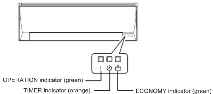
| Indicators | OPERATION (green), TIMER (orange), ECONOMY (green) |
| Error Display | Blinking patterns of indicators indicate error codes |
| Safety Features | Auto shut-off on malfunction; child lock (via remote not specified); protection circuits |
Frequently Asked Questions - ASMG12JLTB FUJITSU
User questions about ASMG12JLTB FUJITSU
0 question about this device. Answer the ones you know or ask your own.
Ask a new question about this device
Download the instructions for your Séparateur in PDF format for free! Find your manual ASMG12JLTB - FUJITSU and take your electronic device back in hand. On this page are published all the documents necessary for the use of your device. ASMG12JLTB by FUJITSU.
USER MANUAL ASMG12JLTB FUJITSU
AIR CONDITIONER Wall Mounted Type
natural_image
Simple line drawing of a rectangular air conditioner unit (no text or symbols)OPERATING MANUAL
Contents
Safety Precautions 1
Indoor Unit Overview and Operations 2
Remote Controller Overview and Operations....3
Care and Cleaning....5
Troubleshooting....7
Error Codes 8
Before using this product, read these instructions thoroughly and keep this manual for future reference.
Safety Precautions
To prevent personal injury or property damage, read this section carefully before you use this product, and be sure to comply following safety precautions.
Incorrect operation due to failure to follow the instructions may cause harm or damage, the seriousness of which is classified as follows:

WARNING CAUTION

This mark warns of death or serious injury. This mark warns of injury or damage to property.

This mark denotes an action that is PROHIBITED.

This mark denotes an action that is COMPULSORY.

WARNING

- This unit contains no user-serviceable parts. Always consult authorized service personnel for repairing, installation, and relocation of this product.
Improper installation or handling will cause leakage, electric shock, or fire.
- In the event of a malfunction such as burning smell, immediately stop operation of the air conditioner, and disconnect all the power supply by turning off the electrical breaker or disconnecting the power plug. Then consult authorized service personnel.
- Take care not to damage the power supply cable. If the supply cord is damaged, it must be replaced by the manufacturer, its service agent or similarly qualified persons in order to avoid a hazard.
- In the event of refrigerant leakage, be sure to keep away from fire or any flammables, and consult authorized service personnel.
- In the event of a thunder storm or any prior sign of a lightning strike, turn off the air conditioner via the remote controller, and refrain from touching the product or the power source to prevent any electrical hazards.

- This appliance is not intended for use by persons (including children) with reduced physical, sensory or mental capabilities, or lack of experience and knowledge, unless they have been given supervision or instruction concerning use of the appliance by a person responsible for their safety. Children should be supervised to ensure that they do not play with the appliance.

- Do not install the unit in area filled with mineral oil such as a factory or area containing a large amount of splashed oil or steam such as a kitchen.
- Do not start or stop the operation of this product by inserting or pulling out the power plug, or by turning on or off the circuit breaker.
- Do not use inflammable gases near the unit.
- Do not expose yourself directly to the cooling airflow for many hours.
- Do not insert your fingers or any other objects into outlet port, open panel, or intake grille.
- Do not operate with wet hands.

CAUTION

- Provide occasional ventilation during use.
• Always operate the unit with air filters installed. - Ensure that any electronic equipment is at least 1 meter away from either the indoor unit or outdoor unit.
- Unplug the power supply cable when not using the indoor unit for an extended period.
- After long period of use, check whether the installation stand does not deteriorate to prevent the unit from falling down.
- The airflow direction and the room temperature should be carefully considered when you use this product in a room with infants, children, elderly or sick persons.
- Do not direct the airflow at fireplaces or heating apparatus.
- Do not block or cover the intake grille and the outlet port.
- Do not apply any heavy pressure to radiator fins.
- Do not climb on, place objects on, or hang objects from the unit.

- Do not place vase or water container on the unit. Do not place any other electrical products or household belongings under indoor unit or outdoor unit.
Dripping condensation from the unit might get them wet, and may cause damage or malfunction of your property.
- Do not expose the unit directly to water.
- Do not use this product for preservation of food, plants, animals, precision equipment, art work, or other objects. This may cause quality deterioration of those items.
- Do not expose animals or plants to the direct airflow.
- Do not drink the drainage from the air conditioner.
- Do not pull the power supply cable to disconnect the plug.
- Do not touch the aluminum fins of heat exchanger built-in the indoor or outdoor unit to avoid personal injury when you install or maintain the unit.
1 Intake grille
Before starting operation, make sure that the intake grille has been shut completely. Incomplete closing might have an effect on the proper working or performance of the product.
2 "MANUAL AUTO" button
Use when you lost the remote controller or remote control malfunction occurs.
| Status Action Mode or operation | ||
| In operation Press more than 3 seconds. Stop | ||
| Stopping Press more than 3 seconds and less than 10 seconds. | AUTO | |
| Press more than 10 seconds. (Only for servicing.*) | ||
| After cleaning Press less than 3 seconds. Filter indicator reset | ||
*:To stop forced cooling, press this button or "START/STOP" button on the remote controller.
3 Front panel
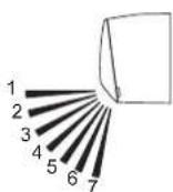
4 Vertical airflow direction louver
Each time you press "SET" button on the remote controller, the angle of the vertical airflow direction louver moves as follows:
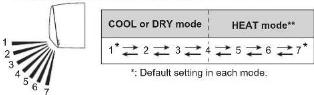
- Do not adjust by hand.
- At the beginning of AUTO or HEAT mode, they may stay position 1 for a while for adjustment.
- If you set the angle to position 5–7 for more than 30 minutes in COOL or DRY mode, they automatically return to position 4. In COOL or DRY mode, if the angle is set to position 5–7 for many hours, condensation may be formed, and the drips may wet your property.
5 Drain hose
6 Remote controller signal receiver
CAUTION
For appropriate signal transmission between remote controller and the indoor unit, keep the signal receiver away from following items:
- Direct sunlight or other strong light
- Flat-panel television screen
In rooms with instantaneous fluorescent lights, such as inverter type ones, the signal may not be transmitted properly. In such a case, consult the store that you purchased the product.
7 ECONOMY indicator (green)
Lights in Economy operation.
⑧ TIMER indicator (orange)
Lights in Timer operation, and blinks slowly when the timer setting error is detected.
As for the timer setting error, refer to "Auto-restart function" on page 4.
9 OPERATION indicator (green)
Lights in normal operation, and blinks slowly in automatic defrosting operation.
10 Horizontal airflow direction louvers
CAUTION
Before you adjust the horizontal airflow direction, make sure that the vertical airflow direction louver has been stopped completely.
Adjust two knobs by hand.
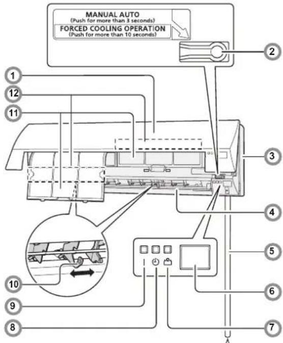
11 Air filter
See page 5
Easy-to-care air filters resist mildew growth.
12 Air cleaning filter
See page 5
Purify or deodorize the air, and provide fresh airflow.
Indoor unit accessories
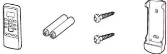
Remote controller
Batteries
Tapping screws (small)
Remote controller holder
WARNING
Take care to prevent infants and small children from accidentally swallowing the batteries.
Battery (AAA/R03/LR03 × 2) loading
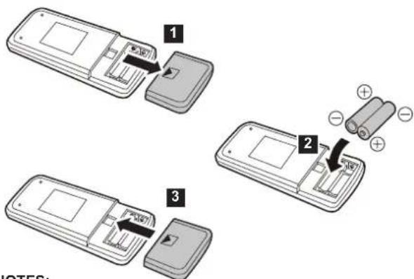
NOTES:
- Use specified type of battery only.
- Do not use new battery and used battery together.
- Batteries can be used about 1 year in ordinary use.
- If the remote control range noticeably got shorten, replace the batteries, and press "RESET" button.
Remote Controller Overview and Operations

CAUTION

• To prevent malfunction or damage of the remote controller:
- Place remote controller at where will not be exposed to direct sunlight or excessive heat.
- Remove batteries if the product is not going to be used for an extended period.
- Exhausted batteries must be removed immediately, and be disposed according to the local laws and regulations of your region.

- If leaking battery fluid comes in contact with your skin, eyes, or mouth, immediately rinse with plenty of clean water, and consult your physician.
- Obstacles such as a curtain or wall between the remote controller and the indoor unit may affect the appropriate signal transmission.

- Do not apply strong shocks to the remote controller.
- Do not pour water on the remote controller.
- Do not attempt to recharge dry batteries.
Remote controller holder installation
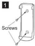
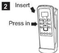
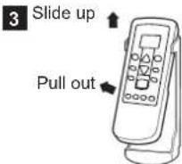
You can quickly start the operation with following 3 steps:
① "START/STOP" button
② "MODE" button

Switches operation mode in following order.
AUTO → COOL —DRY FAN HEAT**
Notes in HEAT mode:\*\*
- At the beginning of the operation, the indoor unit operates at very low fan speed for about 3–5 minutes for preparation, and then switches to the selected fan speed.
• Automatic defrosting operation overrides the heating operation when it is necessary.
③“SET TEMP.” (temperature) buttons

Set desired temperature.
| Temperature setting range | |
| AUTO 18–30 °C | |
| COOL/DRY 18–30 °C | |
| HEAT** | 16–30 °C |
*:Temperature control is not available in FAN mode.
4 "FAN" button

Controls the fan speed.

- When AUTO is selected, the fan speed is automatically adjusted according to the operation mode.
5 "SET" button

Adjusts the vertical airflow direction.
6 "SWING" button

Starts or stops automatic swing of the vertical airflow direction louver.
• Each time you press the button, the vertical airflow direction louver swings as follows:
| COOL or DRY mode | HEAT mode** |
| 1 2 3 4 | 4 5 6 7 |
NOTES:
Swing operation may stop temporarily when the fan in the unit is rotating at very low speed or stopping.
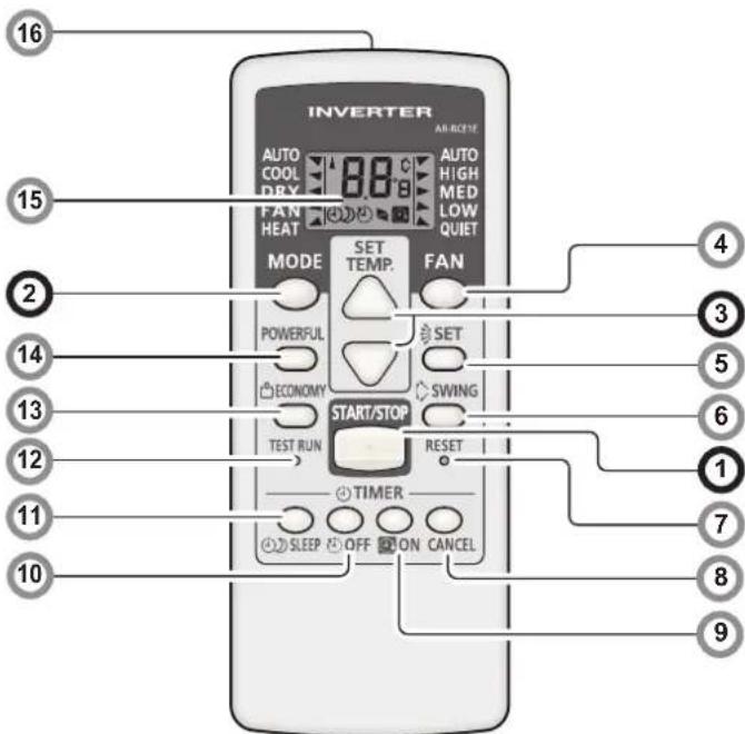
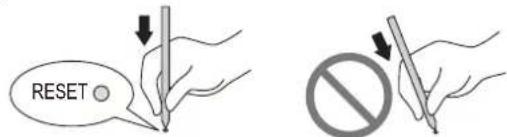
7 "RESET" button
When you press the "RESET" button, press it gently by using the tip of a ballpoint pen or other small object in correct direction as shown in this figure.
8 "TIMER CANCEL" button

Cancels the set timer.
9 "ON TIMER" button

Each time you press the button, the time changes as follows:

- Set the time while the 📋 indicator on the remote controller display is blinking.
10 "OFF TIMER" button

Each time you press the button, the time changes as follows:

- Set the time while the ⏻ indicator on the remote controller display is blinking.
*: The setting must be done within about 3 seconds during the indicator stays solid.
1: The button is controllable only when the air conditioner is on.
**: Heat pump model only
(continued)
Program timer (combined use of the ON timer and the OFF timer)
You can set an integrated ON-OFF or OFF-ON timer as follows:
| ON-OFF | Set the ON timer first.Then set the OFF timer by the air conditioner starts operation controlled with the ON timer earlier set. |
| OFF-ON | Set the OFF timer first.Then set the ON timer by the air conditioner stops operation controlled with the OFF timer earlier set. |
The timer that is set later starts counting down after the counting down of the preceding timer is finished.
NOTE:
If you change the setting value for the timer after the program timer is set, the counting down of the timer will be reset at that moment.
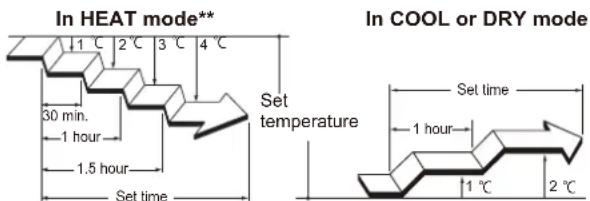
11 "SLEEP TIMER" button

Each time you press the button, the time changes as follows:

- Set the time while the indicator on the remote controller display is blinking.
To repeat the timer, press the button when the indicator is not displayed.
To help you to fall asleep comfortably and prevent excessive warming or cooling in sleep, the Sleep timer controls the temperature setting automatically in accordance with the set time shown as follows. The air conditioner completely turns off after the set time has elapsed.
Note for Timer settings:
Any interruption of the power supply, such as a blackout or cutting off of a circuit breaker, makes the set internal clock go wrong. In such a case, the TIMER indicator on the indoor unit blinks, and you need to readjust the setting.
12 "TEST RUN" button

Only used for the initial test in the unit installation.
Do not press this button under normal use because it will cause incorrect operation.
- During the test run, the OPERATION indicator and the TIMER indicator blink simultaneously.
- To quit the test run that is started unintentionally, you need to turn off the air conditioner by pressing the "START/STOP" button.
13 "ECONOMY" button

Starts or stops Economy operation that saves more electricity consumption than the other operations with a conservative adjustment of the room temperature.
When you press the button, the ECONOMY indicator on the indoor unit turns on.
- In COOL mode, the room temperature will be adjusted at a few degree higher than the defined temperature.
In HEAT mode, the room temperature will be adjusted at a few degree lower than the defined temperature.
- Especially in COOL mode, you can have improved dehumidification without significantly lowering the room temperature.
NOTES:
- In COOL or HEAT mode, the maximum output of this operation is approximately 70 % of usual air conditioning operation.
- This operation cannot be performed during temperature monitoring by AUTO mode.
14 "POWERFUL" button

Starts Powerful operation that enables quick cooling down or warming up of the room.
When you press the button to start the Powerful operation, the indoor unit emits 3 short beeps.
Powerful operation is automatically turned off in the following situations:
- Adjusted room temperature reached to the defined temperature in temperature setting in COOL, DRY, or HEAT mode. - 20 minutes have passed after finishing the Powerful operation mode setting.
It is not turned off automatically during setting of the Powerful operation. NOTES:
- The airflow direction and the fan speed are controlled automatically.
- This operation cannot be performed simultaneously with Economy operation.
To return to normal operation, press the button again. Then the indoor unit emits 2 short beeps.
15 Remote controller display
In this section, all the possible indicators are displayed for description. In actual operation, the display is linked with the button operation, and only shows the necessary indicators for each setting.
16 Signal transmitter
Aim to signal receiver of the indoor unit properly.
- Signal transmit indicator on the remote controller display shows that signal from the remote controller is being transmitted.
- Operating range is approximately 7 m.
- You will hear a beep if the transmitted signal has been sent properly. If there is no beep, press the button on the remote controller again.
Automatic defrosting operation\*\*
When outdoor temperature is very low with high humidity, frost may form on the outdoor unit during the heating operation, and it could reduce the operating performance of the product.
For frost protection, a microcomputer-controlled automatic defrost function is equipped in this air conditioner.
If frost forms, the air conditioner will temporarily stop, and defrost circuit will operate briefly (maximum of 15 minutes.) OPERATION indicator on the indoor unit blinks during this operation.
If frost forms on the outdoor unit after the heating operation, the outdoor unit will stop automatically after it operates for a few minutes. Then the automatic defrosting operation starts.
Auto-restart function
In event of power interruption such as a blackout, the air conditioner stops once. But it restarts automatically and performs previous operation when the power supply is resumed.
If any power interruption occurs after the timer is set, counting down of the timer will be reset.
After the power supply is resumed, the TIMER indicator on the indoor unit blinks to notify you that there has been a timer fault. In such a case, reset the timer for your opportune time.
Malfunctions caused by other electrical devices:
Use of other electrical appliances such as an electric shaver or nearby use of a wireless radio transmitter may cause the malfunction of the air conditioner.
If you encounter such a malfunction, turn off the circuit breaker once. Then turn it on again, and resume operation by using the remote controller.
**: Heat pump model only
Care and Cleaning

CAUTION

- Before cleaning the indoor unit, be sure to turn it off and all the power supply has been disconnected.
- Before starting operation, make sure that the intake grille has been shut completely. Incomplete closing of the intake grille might have an effect on the proper working or performance of the air conditioner.

- Do not touch the aluminum fins of heat exchanger built-in the indoor unit to avoid personal injury when you maintain the unit.
- Do not expose the indoor unit to liquid insecticides or hair sprays.
Daily care
When cleaning the indoor unit body, mind the following:
- Do not use water hotter than 40^ .
- Do not use scouring cleanser, volatile solvents such as benzene or thinner.
- Wipe the unit gently by using soft cloth.
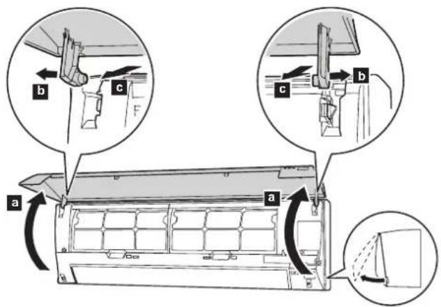
Cleaning the intake grille
1 Open the intake grille in direction of the arrow a. While gently pressing the left and right mounting shafts of the intake grille outward b, remove the intake grille in direction of the arrow c.
2 Wash the intake grille gently with water or wipe it gently with a soft cloth moisten with warm water.
Then wipe it with a dry and soft cloth.
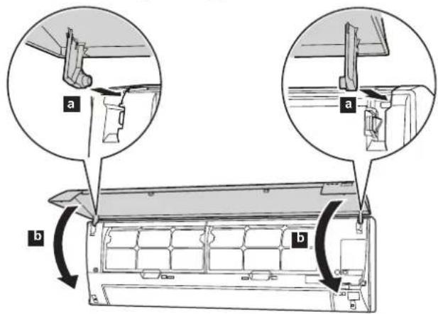
3 While holding the grille horizontal, set the left and right mounting shafts into the pillow blocks at the top of the panel a. To latch each shaft properly, insert the shaft until it snaps.
Then close the intake grille
b
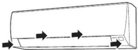
4 Press 4 places on the intake grille to close it completely.
natural_image
Line drawing of a car air conditioner unit with airflow arrows indicating direction (no text or symbols)Cleaning the air filters
Mind that you have a periodical cleaning of the air filters to prevent reducing the operation efficiency of the product.
Using of clogged air filter with dust will lower the product performance, and may cause airflow reduction or increase of operating noise.
Clean the air filters once every 2 weeks under normal use.
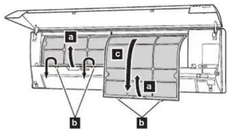
1 Pull up the handle a of the filter in direction of the arrow and release the 2 claws b.
Then pull the filter out with gently sliding it downward
2 Remove dust by using a vacuum cleaner or by washing the filter. When you wash the filter, use neutral household detergent and warm water.
After rinse the filter well, dry it thoroughly in a shaded place before you reinstall it.
3 Attach the air filter with aligning both side of the filter with the panel, and push in the filter fully.
NOTES:
Make sure that 2 claws are firmly snapped to the guide holes on the panel.
Air Cleaning Filter Installation
1 Open the intake grille and remove the air filters.
2 Install the air cleaning filter set (set of 2).
1. Set the air cleaning filter into the air cleaning filter frame.
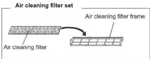
- Engage the latch at both ends of the with the two hooks at the rear of the air cleaning filter frame.
Hook (2 place at the rear)
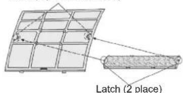
Take care that the air cleaning filter does not project beyond the frame.
- Engage the four fixing locations at the top and bottom of the air cleaning filter frame with the hooks of the air filter.
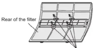
Fixing location, hook (4 places)
3 Install the two air filters and close the intake grille.
- When air cleaning filters are used, the effect will increased by setting the fan speed to "HIGH".
Replacing dirty Air cleaning filters
Replace filters with the following components (purchased separately).
• Polyphenol catechin air cleaning filter : UTR-FA03-2
- Negative air ions deodorizing filter : UTR-FA03-3.
1 Open the intake grille and remove the air filters.
2 Replace them by two new air cleaning filters.
1. Remove the old air cleaning filters reverse order of their installation.
2. Install in the same way as for installation of the air cleaning filter set.
3 Install the two air filters and close the intake grille.
In regard to the Air Cleaning Filters
[Polyphenol catechin air cleaning filter (one sheet)]
- The air cleaning filters are disposable filters. (They cannot be washes and reused.)
- For storage of the air cleaning filters, use the filters as soon as possible after the package has been opened.
(The air cleaning effect decreases when the filters are left in the opened package) - Generally, the filters should be exchanged about every three months.
Please buy dedicated air cleaning filters (UTR-FA03-2) (Sold separately) to exchanging the used dirty air cleaning filters.
[Negative air ions deodorizing filter (one sheet) – light blue]
- The filter should be exchanged about every three years so as to maintain the deodorizing effect.
- Filter frame is not a one-off product.
Please buy dedicated deodorizing filters (UTR-FA03-3) (Sold separately) when exchanging the filters.
Maintenance of Deodorizing Filters
In order to maintain the deodorizing effect, please clean the filter in the follow way once three months.
- Remove the deodorizing filter.
- Clean with water and dry in the air.
1) Flush the filters with high-pressure hot water until the surface of the filters are covered with water. Please flush with diluent neutral detergent. (Never wash by reaming or rubbing, otherwise it will damage the deodorizing effect.)
2) Rinse with water flow.
3) Dry in shade.
- Reinstall the deodorizing filter.
After extended non-use of the unit
If you have shut down the indoor unit for 1 month or more, perform the FAN operation for half a day to dry the internal parts thoroughly before you perform normal operation.
Additional inspection
After long period of use, accumulated dust inside the indoor unit may reduce the product performance even if you have maintained the unit with instructed daily care or cleaning procedures written in this manual. In such a case, the product inspection is recommended.
For more information, consult authorized service personnel.
Troubleshooting

WARNING

In the event of a malfunction such as burning smell, immediately stop operation of the air conditioner, and disconnect all the power supply by turning off the electrical breaker or disconnecting the power plug. Then consult authorized service personnel.
As long as the unit is connected to the power supply, it is not insulated from the power supply even if the unit is turned off.
Following symptoms do not indicate the product malfunction, but they are normal functions or characteristics of this product.
| Symptom Cause See | page | |
| Operation is delayed after restart. | To prevent blowout of the fuse, the compressor will not operate during the protection circuit is working for about 3 minutes after sudden OFF→ON operation of the power supply. | - |
| Noise is heard. | ·During the operation or immediately after stopping the air conditioner, refrigerant flowing sound may be heard. And it is particularly noticeable for 2–3 minutes after starting operation.·During the operation, a slight squeaking sound produced by the minute expansion and contraction of the front panel caused by temperature change may be heard. | - |
| During heating operation, a sizzling sound produced by the automatic defrosting operation may be heard.** | 4 | |
| Smell coming from the unit. | Absorbed room smell generated from interior textile, furniture, or cigarette smoke into the air conditioner may be emitted. | - |
| Mist or steam is emitted from the unit. | In COOL or DRY mode, a thin mist generated by condensation formed with sudden cooling process may be emitted. | - |
| During heating operation, the fan built-in the outdoor unit may stops and rising steam generated by the automatic defrosting operation may be seen. | 4 | |
| Airflow is weak or stops. | ·Immediately after the heating operation is started, the fan speed stays temporarily very low to warm up the internal parts of the unit.**·In HEAT mode, the outdoor unit stops and the indoor unit operates at very low fan speed if the room temperature rises above the set temperature.** | - |
| In HEAT mode, the indoor unit temporarily stops for maximum of 15 minutes to perform the automatic defrosting operation while the OPERATION indicator is flashing.** | 4 | |
| In DRY mode, the indoor unit operates at low fan speed to adjust the room humidity, and may stop from time to time. | - | |
| When the fan speed is set to “QUIET”, the fan rotates at very low speed and the airflow is reduced. | - | |
| When monitoring operation is performed in AUTO mode, the fan rotates at very low speed. - | ||
| Outdoor unit emits water. | During heating operation, the outdoor unit may emit water generated by the automatic defrosting operation.** | - |
Before you call for or request servicing, troubleshoot a problem by performing following checks:
| Symptom Diagnostic | See page | |
| Does not operate at all. | □ Has the circuit breaker been turned off?□ Has there been a power outage?□ Has a fuse blown out or the circuit breaker been tripped? | - |
| □ Is the intake grille closed completely? | 5 | |
| □ Is the timer operating? | 3, 4 | |
| Poor cooling or heating performance. | □ Is the air filter dirty? | 5 |
| □ Is the intake grille or outlet port of indoor unit blocked? | - | |
| □ Is the room temperature adjusted appropriately? | 3 | |
| □ Is a window or door left opened?□ Is direct or strong sunlight shining into the room in cooling operation?□ Are there other heating apparatus or computers operating, or too many people in the room in cooling operation? | - | |
| □ Is the fan speed set to “QUIET”? | 3 |
Immediately stop operation and turn off the electrical breaker in following cases. Then consult authorized service personnel.
- The problem persists even if you perform these checks or diagnostics.
• The OPERATION indicator and TIMER indicator blink while the ECONOMY indicator is blinking fast
If you use a wireless remote controller, the lamp on the photo detector unit will output error codes by way of blinking patterns. See the lamp blinking patterns in the table. An error display is displayed only during operation.
[Troubleshooting with the indoor unit display]
| Error display | Description | ||
| OPERATION indicator (green) | TIMER indicator (orange) | ECONOMY indicator (green) | |
| (1) ● (1) ◇ | Serial communication error | ||
| (3) ● (2) ◇ | Indoor unit PCB model information error | ||
| (3) ● (5) ◇ | Manual auto switch error | ||
| (4) ● (1) ◇ | Room temp. sensor error | ||
| (4) ● (2) ◇ | Indoor unit Heat Ex. Middle temp.sensor error | ||
| (5) ● (1) ◇ | Indoor unit fan motor error | ||
| (5) ● (15) ◇ | Indoor unit error | ||
| (6) ● (2) ◇ | Outdoor unit main PCB model information error or communication error | ||
| (6) ● (3) ◇ | Inverter error | ||
| (6) ● (4) ◇ | Active filter error, PFC circuit error | ||
| (6) ● (5) ◇ | Trip terminal L error | ||
| (6) ● (10) ◇ | Display PCB microcomputers communication error | ||
| (7) ● (1) ◇ | Discharge temp. sensor error | ||
| (7) ● (3) ◇ | Outdoor unit Heat Ex. liquid temp. sensor error | ||
| (7) ● (4) ◇ | Outdoor temp. sensor error | ||
| (8) ● (4) ◇ | Current sensor error | ||
| (9) ● (4) ◇ | Trip detection | ||
| (9) ● (5) ◇ | Compressor rotor position detection error | ||
| (9) ● (7) ◇ | Outdoor unit fan motor error | ||
| (9) ● (9) ◇ | 4-way valve error | ||
| (10) ● (1) ◇ | Discharge temp. error | ||
Display mode • : 0.5s ON / 0.5s OFF
◇ : 0.1s ON / 0.1s OFF
( ) : Number of flashing.
- AIR CONDITIONER Wall Mounted Type
- OPERATING MANUAL
- Contents
- Safety Precautions
- WARNING CAUTION
- WARNING
- CAUTION
- Intake grille
- "MANUAL AUTO" button
- Front panel
- Vertical airflow direction louver
- Drain hose
- Remote controller signal receiver
- ECONOMY indicator (green)
- ⑧ TIMER indicator (orange)
- OPERATION indicator (green)
- Horizontal airflow direction louvers
- Air filter
- Air cleaning filter
- NOTES:
- Remote Controller Overview and Operations
- ① "START/STOP" button
- ② "MODE" button
- Notes in HEAT mode:\*\*
- ③“SET TEMP.” (temperature) buttons
- "FAN" button
- "SET" button
- "SWING" button
- "RESET" button
- "TIMER CANCEL" button
- "ON TIMER" button
- "OFF TIMER" button
- Program timer (combined use of the ON timer and the OFF timer)
- NOTE:
- "SLEEP TIMER" button
- Note for Timer settings:
- "TEST RUN" button
- "ECONOMY" button
- "POWERFUL" button
- Remote controller display
- Signal transmitter
- Automatic defrosting operation\*\*
- Auto-restart function
- Malfunctions caused by other electrical devices:
- Care and Cleaning
- Daily care
- Cleaning the intake grille
- Cleaning the air filters
- Air Cleaning Filter Installation
- Replacing dirty Air cleaning filters
- [Polyphenol catechin air cleaning filter (one sheet)]
- [Negative air ions deodorizing filter (one sheet) – light blue]
- Maintenance of Deodorizing Filters
- After extended non-use of the unit
- Additional inspection
- Troubleshooting
Brand : FUJITSU
Model : ASMG12JLTB
Category : Séparateur