
PWS-4 - Uncategorized ELECTRO-VOICE - Free user manual and instructions
Find the device manual for free PWS-4 ELECTRO-VOICE in PDF.


| Product Type | Programmable Wall Station Front Unit |
| Model | PWS-4 |
| Brand | Electro-Voice |
| Dimensions (W x H x D) | 48 x 105 x 34 mm |
| Weight | 80 g |
| Supply Voltage | 5 V DC (via PWS-C coupler) |
| Current Consumption | 35 mA |
| Power Consumption | 175 mW |
| Button Configuration | 4 programmable buttons with green status LEDs, 2 Up/Down buttons, 4-LED chain |
| Communication Interface | CAN-Bus (via PWS-C coupler) |
| Maximum Front Units per Coupler | 3 (daisy-chained) |
| Configurable via | IRIS-Net software |
| Operating Temperature Range | -5 °C to +40 °C |
| Certification | CE, FCC Part 15, ICES-003 |
| Intended Applications | Stadiums, theaters, cruise ships, schools, airports, conference centers, etc. |
| Cleaning Instructions | Clean only with a dry cloth |
| Safety Precautions | Do not expose to rain or moisture; connect only to mains with protective earthing |
| Firmware Update | Via IRIS-Net |
| Diagnostic Mode | Yes – query hardware parameters without dismounting |
Frequently Asked Questions - PWS-4 ELECTRO-VOICE
User questions about PWS-4 ELECTRO-VOICE
0 question about this device. Answer the ones you know or ask your own.
Ask a new question about this device
Download the instructions for your Uncategorized in PDF format for free! Find your manual PWS-4 - ELECTRO-VOICE and take your electronic device back in hand. On this page are published all the documents necessary for the use of your device. PWS-4 by ELECTRO-VOICE.
USER MANUAL PWS-4 ELECTRO-VOICE
Mounting and Configuration 8
Initial Operation 10
Hardware Configuration 11
CAN-Status-LED 15
Connection 15
Find Function 17
Diagnostic Mode 17
Automatic Configuration 18
Firmware Update 18
CAN-Bus Principles 19
INHALT
Einführung 23
Überblick 23
Declaration of Conformity 44
Setting CAN-Address via DIP-Switch ADDRESS 45
IMPORTANT SAFETY INSTRUCTIONS
The lightning flash with arrowhead symbol, within an equilateral triangle is intended to alert the user to the presence of uninsulated "dangerous voltage" within the product's enclosure that may be of sufficient magnitude to constitute a risk of electric shock to persons.
The exclamation point within an equilateral triangle is intended to alert the user to the presence of important operating and maintenance (servicing) instructions in the literature accompanying the appliance.
- Read these instructions.
- Keep these instructions.
- Heed all warnings.
- Follow all instructions.
- Do not use this apparatus near water.
- Clean only with a dry cloth
- Do not block any ventilation openings. Install in accordance with the manufacture's instructions.
- Do not install near heat sources such as radiators, heat registers, stoves, or other apparatus (including amplifiers) that produce heat.
- Do not defeat the safety purpose of the polarized or the grounding-type plug. A polarized plug has two blades with one wider than the other. A grounding type plug has two blades and a third grounding prong. The wide blade or the third prong are provided for your safety. If the provided plug does not fit into your outlet, consult an electrician for replacement of the obsolete outlet.
- Protect the power cord from being walked on or pinched particularly at plugs, convenience receptacles, and the point where they exit from the apparatus.
-
Only use attachments/accessories specified by the manufacturer.
-
Use only with the cart, tripod, bracket, or table specified by the manufacturer, or sold with the apparatus. When a cart is used, use caution when moving the cart/apparatus combination to avoid injury from tip-over.

- Unplug this apparatus during lightning storms or when unused for a long period of time.
- Refer all servicing to qualified service personnel. Servicing is required when the apparatus has been damaged in any way, such as power-supply cord or plug is damaged, liquid has been spilled or objects have fallen into the apparatus, the apparatus has been exposed to rain or moisture, does not operate normally, or has been dropped.
- Do not expose this equipment to dripping or splashing and ensure that no objects filled with liquids, such as vases, are placed on the equipment.
- To completely disconnect this equipment from the AC Mains, disconnect the power supply cord plug from the AC receptacle.
- The mains plug of the power supply cord shall remain readily operable.
Management of WEEE (waste electrical and electronic equipment) (applicable in Member States of the European Union and other European countries with individual national policies on the management of WEEE) The symbol on the product or on its packaging indicates that this product may not be treated as regular household waste, but has to be disposed through returning it at a Telex dealer.
IMPORTANT SERVICE INSTRUCTIONS
CAUTION: These servicing instructions are for use by qualified personnel only. To reduce the risk of electric shock, do not perform any servicing other than that contained in the Operating Instructions unless you are qualified to do so. Refer all servicing to qualified service personnel.
- Security regulations as stated in the EN 60065 (VDE 0860 / IEC 65) and the CSA E65 - 94 have to be obeyed when servicing the appliance.
- Use of a mains separator transformer is mandatory during maintenance while the appliance is opened, needs to be operated and is connected to the mains.
- Switch off the power before retrofitting any extensions, changing the mains voltage or the output voltage.
- The minimum distance between parts carrying mains voltage and any accessible metal piece (metal enclosure), respectively between the mains poles has to be 3 mm and needs to be minded at all times. The minimum distance between parts carrying mains voltage and any switches or breakers that are not connected to the mains (secondary parts) has to be 6 mm and needs to be minded at all times.
- Replacing special components that are marked in the circuit diagram using the security symbol (Note) is only permissible when using original parts.
- Altering the circuitry without prior consent or advice is not legitimate.
- Any work security regulations that are applicable at the locations where the appliance is being serviced have to be strictly obeyed. This applies also to any regulations about the work place itself.
- All instructions concerning the handling of MOS-circuits have to be observed.
NOTE: SAFETY COMPONENT (MUST BE REPLACED BY ORIGINAL PART)

1 Introduction
1.1 Overview
The programmable wall stations of the modular PWS system (Programmable Wall Station) allow local control and operation of various devices and systems via CAN-Bus. A programmable wall station lets you control several functions, for example: source selection, volume control, muting or powering on/off devices. In addition, using a suitable central control unit allows controlling a variety of facilities in a building (light, heating/air condition, etc.).
The minimum configuration for the operation of a programmable wall station consists of:
• A front unit (e.g. PWS-4)
• A CAN coupler (PWS-C)
- A software configuration created in IRIS-Net™ and transferred to the programmable wall station via CAN-Bus
- A CAN-Bus master unit to be controlled (e.g. Electro-Voice NetMax N8000)
The front units represent the part of the programmable wall station for the user to access, i.e. the user interface. Different front units with differing numbers and types of controls or indicators are available. A number of front units grouped in a single programmable wall station have to be connected in series, with up to three front units connected to a single bus coupler.
The CAN-Bus coupler PWS-C provides connection between front units and the CAN-Bus. The maximum number of units connected to a CAN-Bus (e.g. PWS-C, Remote Amplifier, etc.) depends on employed central control unit. Please consult the corresponding manuals.
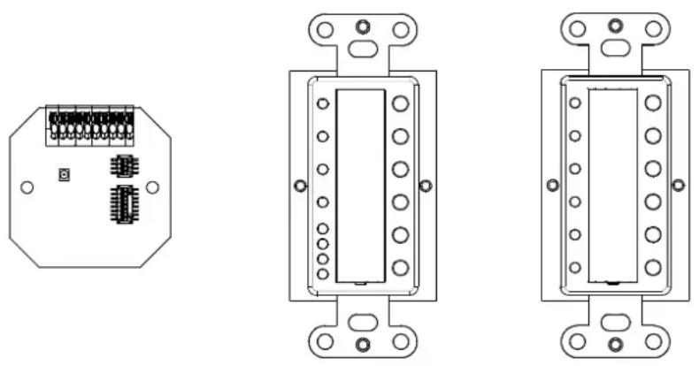
CAN-Bus coupler PWS-C Front unit PWS-4 Front unit PWS-6
1.2 Applications
PWS panels can be included in any audio installation, for example:
• Stadiums and theaters
- Cruise ships
- Multi-purpose halls
• Schools and Universities
• Government agencies
• Airports
- Theme parks
• Exhibition centers and museums
• Conference centers and hotels
1.3 IRIS-Net™
When shipped, programmable wall stations have not been configured yet. The programming of control and indication functions is done using the PC software IRIS-Net™ (Intelligent Remote & Integrated Supervision). After transferring the custom configuration to the programmable wall station, the PWS becomes functional and it is able to control the system components (N8000, remote control amplifiers, etc.) independent of a PC or IRIS-Net™. Simultaneous Control from a PWS and IRIS-Net™ is possible.
The IRIS-Net™ help files contain all the information on configuration, operation and monitoring of all programmable wall station functions. The following illustration shows an example of a PWS system in IRIS-Net™.
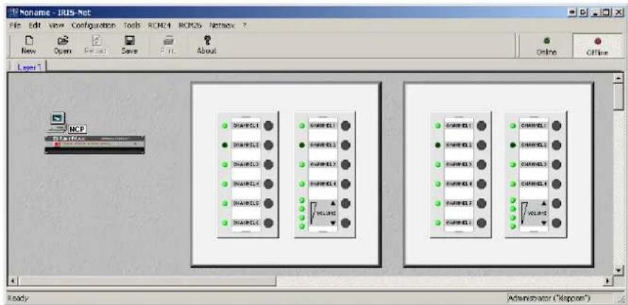
Illustration 1.1: PWS system in IRIS-Net
2 CAN-Bus coupler PWS-C
The CAN-Bus coupler PWS-C provides connection between front units (e.g. PWS-4) and the CAN-Bus. The CAN-Bus coupler registers the activation of controls on the connected front units and sends the needed information via CAN-Bus to the devices to be controlled, but also directs information received from the CAN-Bus to the control units for indication. The CAN-Bus coupler offers connectors for CAN-Bus and power supply as well as DIP switches for the CAN-Bus configuration (baud rate, bus termination and CAN-Bus address). The CAN-Bus coupler PWS-C is suitable for European and US-type flush-mount boxes.
Front view:
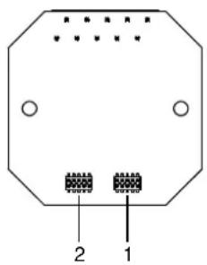
1 Connector for the front unit
2 Connector for future extensions
Rear view:
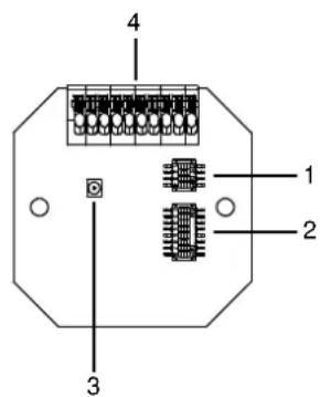
1 DIP switch TERM/BAUD for setting baud rate and termination of the CAN-Bus (see page 11)
2 DIP switch ADDRESS for setting the CAN-address (see page 14)
3 CAN Status-LED for monitoring communication on the CAN-Bus
4 Terminal for CAN-Bus and supply voltage (see page 15)
Default settings:
| Parameter Value | |
| Baud rate PROG mode (10 kbaud, changeable via IRIS-NetTM) | |
| Termination off | |
| CAN-Bus address 00 (CAN-Bus off, Stand-alone) | |
3 PWS Front Unit PWS-4/PWS-6
PWS-4 and PWS-6 are front units of the modular PWS system. They are meant for installation in a US-type wall box. Typical applications are: source selection, volume control and preset-switching.
All controls and indicators of the front units are freely configurable via IRIS-Net™. Individually labeling the controls and indicators according to their assign functions is possible after removing the label field cover. The front units PWS-4 or PWS-6 are being used in combination with the CAN-Bus coupler PWS-C. Up to three front units can be operated on a single PWS-C.
3.1 PWS-4
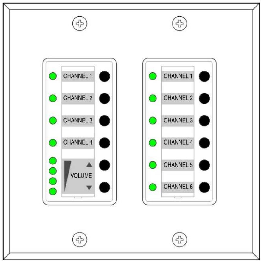
The PWS-4 has in total 6 buttons, with the upper four buttons having a separate Status-LED, each. The two lower buttons can be used as Up/Down buttons. The set parameter status is signaled via LED-chain.
Front view:
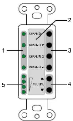
1 Status-LEDs for the function keys (3)
2 Label field
3 Freely configurable function keys
4 Up/Down buttons
5 LED-chain indicates a parameter's value that has been changed using the Up/Down buttons (4)
Rear view:
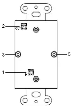
1 Connector for the PWS-C or input socket (IN) for connecting the PWS-4 to the previous front unit in the chain
2 Output socket (OUT) for connecting the PWS-4 to the next front unit in the chain
3 Mechanical lock for the PWS-C plus cover
3.2 PWS-6
The PWS-6 has 6 buttons with Status-LEDs.
Front view:
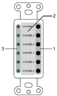
1 Freely configurable function keys
2 Label field
3 Status-LEDs for the function keys (1)
Rear view:
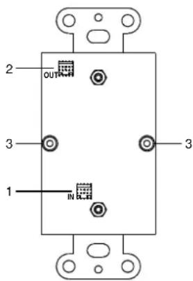
1 Connector for the PWS-C or input socket (IN) for connecting the PWS-6 to the previous front unit in the chain
2 Output socket (OUT) for connecting the PWS-6 to the next front unit in the chain
3 Mechanical lock for the PWS-C plus cover
3.3 Mounting and Configuration
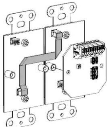
The front units PWS-4 or PWS-6 are connected with two screws to the CAN-Bus coupler PWS-C (see page 11). All front units of a programmable wall station have to be connected in series. Front units are daisy chained by connecting the output socket (OUT) of a front unit to the input socket (IN) of the next unit in the chain.
NOTE:
Connecting sockets of the same type (IN to IN or OUT to OUT) is not permissible.
Only the supplied connection cables should be used for proper operation. The following illustration shows the connection of two front units of a programmable wall station.
natural_image
Technical line drawing of an electrical connector assembly (no text or symbols)Abbildung 3.1: Connecting two front units of a programmable wall station
Other than connections, no physical configuration of the front units is required, as the assignment of functions and other configurations are performed in IRIS-Net™. Adjacent front units have to be installed and connected in the following order: from left to right and from top to bottom.
4 Initial Operation
When shipped, PWS panels have not been configured yet. The following illustration provides an overview of the entire procedure of installing and configuring a PWS for the first time. Please also refer to the descriptions of other connected devices in the corresponding chapters as well as the IRIS-Net™ on-line help feature.
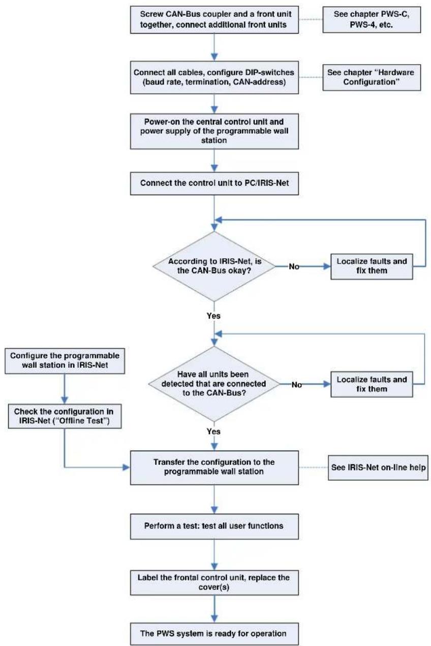
flowchart
graph TD
    A["Screw CAN-Bus coupler and a front unit together, connect additional front units"] --> B["Connect all cables, configure DIP-switches (baud rate, termination, CAN-address)"]
    B --> C["Power-on the central control unit and power supply of the programmable wall station"]
    C --> D["Connect the control unit to PC/IRIS-Net"]
    D --> E{According to IRIS-Net, is the CAN-Bus okay?}
    E -->|No| F["Localize faults and fix them"]
    F --> E
    E -->|Yes| G{Have all units been detected that are connected to the CAN-Bus?}
    G -->|No| H["Localize faults and fix them"]
    H --> G
    G -->|Yes| I["Transfer the configuration to the programmable wall station"]
    I --> J["Perform a test: test all user functions"]
    J --> K["Label the frontal control unit, replace the cover(s)"]
    K --> L["The PWS system is ready for operation"]
    L --> I
    A --> M["See chapter PWS-C, PWS-4, etc."]
    B --> N["See chapter "Hardware Configuration""]
    G --> O["Configure the programmable wall station in IRIS-Net"]
    G --> P["Check the configuration in IRIS-Net ("Offline Test")"]
NOTE:
The system automatically recognizes and configures spare units (see page 18)
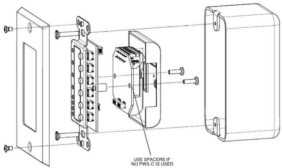
Mounting a Programmable wall station in a US Single Gang Wall Box
For mounting a programmable wall station you have to lock the PWS-C and a front unit of a programmable wall station together using two screws. Using the supplied connection cables, connect additional front units. Please also refer to this manual's corresponding chapters describing the connection procedure for the front units being used.
4.1 Hardware Configuration
The DIP-switches of the PWS-C allow setting the baud rate (page 11), termination (page 13), and CAN-address (page 14). An overview of default DIP-switch settings is provided on page 6.
Baud Rate
CAUTION: All devices on the CAN-Bus have to be set to the same baud rate.
Determination of a suitable baud rate
The maximum allowable baud rate of the CAN-Bus is indirect proportion to the bus length. For smaller networks, baud rates of up to 500 kbit/s are possible. Large networks require a lower baud rate (down to the minimum baud rate of 10 kbit/s). The following table illustrates the relationship between baud rate and bus length, i.e. network dimensions. Generally, bus lengths over 1000 meters should always employ CAN-repeaters.
| Baud rate (in kbit/s) | Bus-length (in m) |
| 500 100 | |
| 250 250 | |
| 125 500 | |
| 62,5 1000 | |
| 20 2500 | |
| 10 5000 |
Table 4.1: Baud rate and Bus-length in CAN-networks
Setting the Baud Rate
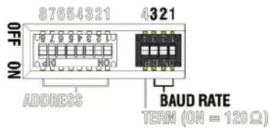
Setting the bus coupler's baud rate is possible by using switches 1, 2 and 3 of the TERM/BAUD DIP-switches. Potential baud rates and corresponding switch settings are shown in the following table. Only when set to PROG Mode, it is possible to change the programmable wall station's baud rate via IRIS-Net™. With all other switch settings, the previously selected value for the baud rate is maintained.
A dark shaded field in the table marks the default value when shipped. In PROG mode, the default data rate is 10 kbit/s.
| DIP switch TERM/BAUD | Baud rate (in kbit/s) | ||
| Switch 3 Switch 2 Switch 1 | |||
| OFF OFF OFF 10 | |||
| OFF OFF ON 20 | |||
| OFF ON OFF 62.5 | |||
| OFF ON ON 125 | |||
| ON OFF OFF | 250 | ||
| ON OFF ON | 500 | ||
| ON | ON OFF not available | ||
| ON | ON ON PROG mode | ||
Table 4.2: Setting the baud rate
NOTE: Changing a previously set fixed baud rate is not possible via IRIS-Net ^™ . The PWS must be in PROG mode to allow the changing of the baud rate via IRIS-Net ^™ .
Setting a default baud rate in PROG mode
As shown in the above table, setting a fixed baud rate is possible when connecting a PWS-C to an already existing CAN-Bus. When connecting a PWS-C in PROG mode, setting the baud rate directly on the PWS-C is possible by following these instructions:
- Activate the power supply of the PWS-C
- Set the desired baud rate using the DIP-switch TERM/BAUD (see page 12)
- Wait until the new baud rate is adopted, which is signaled by a dimmed CAN-Status-LED.
NOTE:
The CAN-Status-LED light for 3 seconds whenever changes are applied to the DIP-switches with the power supply being activated. The new setting is adopted only when the CAN-Status-LED is dimmed.
- PROG mode settings with DIP-switch TERM/BAUD (see page 12)
The PWS-C can now be taken into operation with the baud rate set under step 2.
Termination
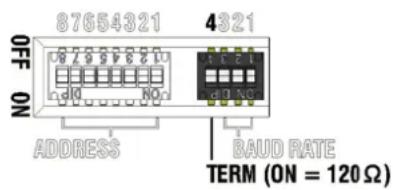
Both ends of a CAN-Bus have to be terminated using a 120 Ω terminator. Missing or erroneous termination can result in malfunction. Contact 4 of DIP-switch 1 allows activating the PWS-C's integrated terminator (see the following table).
A dark shaded field in the table marks the default setting when shipped.
| DIP switch 1, Contact 4 Termination | |
| OFF open | |
| ON | closed (120 Ω) |
Table 4.3: CAN-Bus Termination
The following illustration provides an example of a NetMax-Systems, with Remote Power Amps and programmable wall station being connected via CAN-Bus. Both ends of the CAN-Bus are terminated using terminators.
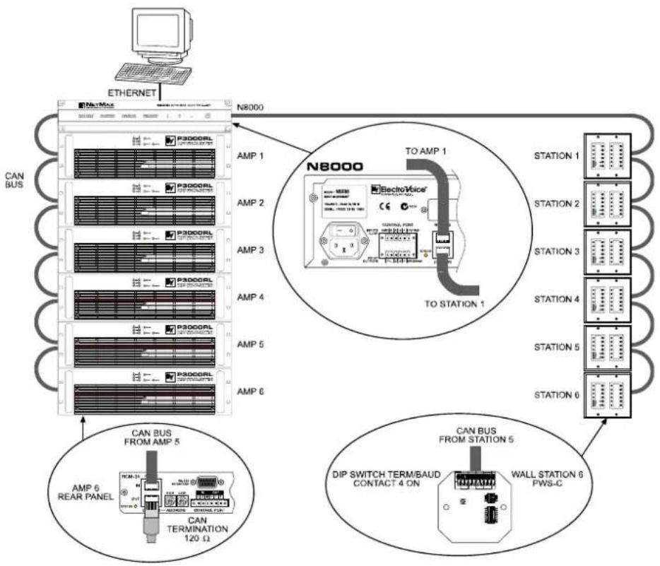
flowchart
graph TD
    A["Computer"] --> B["ETHERNET"]
    B --> C["N8000"]
    C --> D["N8000"]
    D --> E["TO AMP 1"]
    D --> F["TO STATION 1"]
    D --> G["DIP SWITCH TERM/BAUD CONTACT 4 ON"]
    D --> H["WALL STATION 6 PWS-C"]
    C --> I["AMP 1 AMP 2 AMP 3 AMP 4 AMP 5 AMP 6"]
    C --> J["CAN BUS FROM AMP 5 AMP 6 REAR PANEL"]
    C --> K["CAN BUS FROM STATION 5"]
CAN address
CAUTION:
To prevent network faults, each CAN address may exist once only throughout a system. Conflicts on the network would be the result.
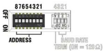
Every programmable wall station has to have a unique CAN address to be identified on the CAN-Bus. The usable address range is: 1 (01 hex) up to 250 (FA hex). The PWS-C's ADDRESS DIP switch (see page 6) allows specifying the CAN address by setting a two-digit hexadecimal number. A table of possible CAN addresses and corresponding DIP-switch settings is provided on page 45.
The default CAN address when shipped is 0 (00 hex).
NOTES:
Various programmable wall stations of a system can be easily configured when their CAN addresses are in consecutive order.
A programmable wall station is disconnected from the CAN-Bus when its CAN address has been set to 0.
If the setting of the DIP-switch is changed, the CAN status LED lights up for 3 seconds. The new setting becomes effective when the CAN status LED is dimmed.
4.2 CAN-Status-LED
The entries in following table are arranged after falling priority, i.e. if two conditions arise at the same time, only the upper condition in the table is indicated.
| CAN-Status-LED Description | |
| Off No power supply | |
| Continuously lit Firmware Update / Configuration in progress | |
| Continuously lit for 3 seconds Changes applied to the DIP-switch setting are adopted | |
| Blinks fast (50 ms ON, 50 ms OFF) Find function active | |
| Activation for 100 ms Sending data | |
| Blinks every second twice for 100 ms | Error state (Hardware fault, wrong configuration, no connection to a CAN unit, missing/wrong panel) |
| Blinks rhythmically every 3 seconds for 100 ms | The PWS-C is separated from the CAN-Bus via software (CAN address 00) |
| Blinks rhythmically every second for 100 ms | Normal operation, no data transfer |
Table 4.4: CAN-Status-LED - modes of indication
4.3 Connection
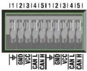
The PWS-C has a 10-pole terminal clip for the connection of CAN-Bus signal transmission and power supply. Using cable with diameters between 0.5 mm and 0.8 mm (20 -24 AWG) is possible. For further information, please refer to the chapter "cable specifications" on page 20.
| Connection Description | |
| Cable shield | |
| GND Operating voltage (-) / CAN_GND | |
| VCC Operating voltage (+) | |
| CAN L CAN_L | |
| CAN H CAN_H | |
NOTE: Power supply ground and CAN-Bus ground are not galvanically separated. The potential difference on the GND-line may not exceed 5 volts.
Connecting the CAN-Bus
Comprehensive guidelines regarding cabling and bus length are provided in chapter "CAN-Bus Principles" starting on page 19.
Supply Voltage
Programmable wall stations need to be operated on a power source that delivers a direct-current voltage between 9 volts and 58 volts. A central power supply unit or local power sources can be used if various wall panels are operated on a single CAN-Bus. When using a central power supply unit, the supply voltage is carried along with CAN-Bus signal transmission. The employed power supply unit's capacity has to match the maximum power requirements of the wall panels.
Power Rating Evaluation Example:
The total power rating for a wall station that consists of 1 PWS-C, 1 PWS-4 and 2 PWS-6 can be evaluated by simply summing up the power consumption of all panels (see individual specifications), i.e.: 1^480mW + 1^175mW + 2^*150mW = 955mW
The following illustration shows the connection between an Electro-Voice NetMax N8000 System Controller and a wall panel using a Dynacord NRS 90257 (PART NO. D121789) 24 volts power supply unit and a RJ45 adapter board NRS 90226 (PART NO. D121678).
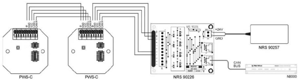
flowchart
graph TD
    A["PWS-C"] -->|+5V 5V CAN| B["NRS 90226"]
    C["PWS-C"] -->|+5V 5V CAN| B
    D["NRS 90257"] -->|+24V GND| B
    B --> E["CAN BUS"]
    B --> F["N8000"]
| PWS-C NRS 90226 | |
| ± | G |
| GND GND | |
| VCC +24V | |
| CAN L 5 | |
| CAN H 4 | |
4.4 Find Function
The Find Function simplifies identifying a programmable wall station when a variety of (identical) wall stations are operated on the same CAN-Bus. When the Find Function is active, the CAN-STATUS-LED on the PWS-C's rear blinks (and, if existing, the LEDs of the front unit selected in IRIS-Net ^™ ) as shown in the table on page 15. The LEDs of all other wall stations for which the Find Function has not been activated do not light. Notes on how to use the Find Function can be found in the IRIS-Net ^™ documentation.
4.5 Diagnostic Mode
The diagnostic mode allows the convenient querying the hardware configuration of a PWS wall panel, including CAN-Bus address, baud rate, etc., without dismounting the wall panel. In diagnostic mode the front unit that is directly connected to the CAN-Bus coupler is being queried.
| Button (numbered from top to bottom) | Indicated Parameter Annotation | |
| 1 | CAN-Status-LED and DIP-switch fault indication | The information indicated by the upper LED is identical to the information signaled by the CAN-Status-LED on the PWS-C (see page 15). The second LED from the top lights when the PWS-C's DIP-switches have been invalidly set. |
| 2 | CAN-address (low-order digit) | Switch setting 1-4 (LOW) of the DIP-switch ADDRESS (see page 14) from top to bottom |
| 3 | CAN-address (high-order digit) | Switch setting 5-8 (HIGH) of the DIP-switch ADDRESS (see page 14) from top to bottom |
| 4 Baud rate | Setting of contacts 1-3 of the DIP-switch TERM/BAUD (see page 11), setting of contact 4 (Termination) is not indicated | |
Table 4.5: Parameters of the bus coupler that can be queried in diagnostic mode
Manually accessing diagnostic mode is possible under following conditions:
- Either the CAN-Bus is out of operation (e.g. when CAN-address 0 has been set)
- or activation for the wall panel's diagnostic mode has been unlocked in IRIS-Net™ (refer to the online help in IRIS-Net™).
If one of these conditions is true, please proceed as follows to access diagnostic mode:
-
Press any button on the programmable wall station and hold it down for at least 5 seconds. Three times flashing all of the LEDs on the front panel of the PWS indicates that diagnostic mode has been activated. Following that, the 4 upper LEDs light, as explained in line “1” of table 4.5
-
The 4 upper buttons of this front unit can be used to query the desired parameters. Parameters that can be queried in diagnostic mode are listed in table 4.5.
Diagnostic mode is automatically cancelled under following conditions:
- Either no button on the front unit has been pressed for at least 15 seconds
• or the CAN-Bus is operational again - or unlocking the diagnostic mode has been deactivated in IRIS-Net™.
4.6 Automatic Configuration
If a PWS-C of an existing PWS system needs to be replaced,
- the new device's firmware version has to be the same or newer than the one of the previously installed unit and
- the settings of the DIP-switches ADDRESS and TERM/BAUD of the old and the new model have to be identical.
NOTE: If the to be replaced unit had been used in PROG-Mode with a baud rate unequal 10 kbit/s, the factory default baud rate of the new device needs to be set (see page 13).
If these two conditions are true, the wall station will automatically be configured and put into operation by the CAN-Bus master.
4.7 Firmware Update
Updating the firmware of a wall panel is done in IRIS-Net ^™ . The current firmware version is included in the IRIS-Net ^™ package. If an error occurs during the firmware update procedure (e.g. missing supply voltage), you can simply start the entire process from the beginning. For detailed information about the update procedure, please refer to the online help in IRIS-Net ^™ .
5 CAN-Bus Principles
The network topology used by the CAN bus is based on the so-called “bus or line topology”, i.e. all participants are connected via a single two-wire cable (Twisted-Pair cable, shielded or unshielded) with the cabling running from one participant on the bus to the next, allowing unlimited communication among all devices. In general, it does not matter if the bus member is a power amplifier, a N8000 or a UCC1 USB-CAN converter. Thus, the N8000 can be connected at any place of the CAN bus. In total, up to 100 devices can be connected to one CAN bus.
The CAN bus has to be terminated with a 120 Ω terminating resistor at both ends. If the termination is missing or an improper resistor value is used, network errors can occur as a signal is reflected on the bus at both bus ends. Because of the superposition of the reflection with the original signal, the original signal is blurred. This may result in the loss of data. In order to prevent or minimize reflections at the bus ends, terminators are used as they "absorb" the energy of the signal.
Since the CAN interfaces of all EVI Audio appliances are galvanically separated from the rest of the circuitry, network cabling also carries a common ground conductor (CAN_GND) ensuring that all CAN-interfaces in the network are connected to a common ground potential.
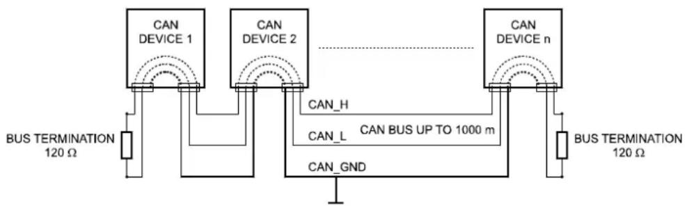
flowchart
graph TD
    A["CAN DEVICE 1"] --> B["BUS TERMINATION 120 Ω"]
    C["CAN DEVICE 2"] --> D["BUS TERMINATION 120 Ω"]
    E["CAN DEVICE n"] --> F["BUS TERMINATION 120 Ω"]
    B --> G["CAN_GND"]
    D --> H["CAN_L"]
    F --> I["CAN_H"]
    style A fill:#f9f,stroke:#333
    style C fill:#f9f,stroke:#333
    style E fill:#f9f,stroke:#333
    style B fill:#ccf,stroke:#333
    style D fill:#ccf,stroke:#333
    style F fill:#ccf,stroke:#333
Bus Topology of the CAN bus
By using a CAN bus repeater a connection between two independent and self-contained CAN bus systems can be created. Thus, the following can be achieved:
- Increase of the max. number of members
A maximum of 100 devices can be connected to one CAN bus. This number can be increased up to 250 by connecting several CAN bus systems. This limitation of exactly 250 devices results from the addressing scheme used by the CAN bus. The addressing scheme allows the allocation of a maximum of 250 different CAN device addresses.
- Improvement of signal quality
With CAN bus systems, whose bus length exceeds 1000 meters, a CAN bus repeater should be used. The CAN bus repeater accomplishes a signal processing and a reinforcement of the bus signals. The internal running time of the repeaters of approx. 150 ns corresponds to an extension of the bus over approx. 45 meters.
- Creation of alternative network topologies
By using one or several repeaters, not only the above-mentioned bus topology, but the creation of other network topologies are also possible.
CAN-Bus Cabling Specifications
According to the ISO 11898-2 standard, CAN-bus data transfer cabling has to be carried out using Twisted-Pair cables with or without shielding providing a characteristic impedance of 120 . Both ends of a CAN-bus need to be terminated with 120 termination-plugs. The maximum bus-length depends on the actual data transfer rate, the kind of data transfer cable being used, as well as the total number of participants on the bus. The following table shows the most essential requirements for CAN-networks consisting of up to 64 participants.
| Bus Length (in m) | Data Transmission Cable | Termination (in Ω) | Max. Data Transfer Rate | |
| Resistance per Unit Length (in mΩ/m) | Cable Diameter | |||
| 0...40 < 70 | 0,25...0,34 mm2 | AWG23, AWG22 | 124 1000 | kbit/s at 40 m |
| 40...300 < 60 | 0,34...0,6 mm2 | AWG22, AWG20 | 127 500 k | bit/s at 100 m |
| 300 ... 600 < | 40 0,5...0,6 mm2 | AWG 20 | 150...300* 100 | kbit/s at 500 m |
| 600...1000 < | 26 0,75...0,8 mm2 | AWG 18 | 150...300* 62 | ,5 kbit/s at 1000 m |
* With longer cables and many participants on the CAN-bus, termination resistors with higher impedance than the specified 120 Ω are recommended to reduce the ohmic load of the interface drivers and therefore the voltage drop between the two cable-ends.
The following table is meant for first assessment of necessary cable diameters for different bus lengths and bus-participant numbers.
| Bus Length (in m) | Number of Units on the CAN-Bus | ||
| 32 64 | 100 | ||
| 100 | 0,25 mm^2 / AWG24 | 0,34 mm^2 / AWG22 | 0,34 mm^2 / AWG22 |
| 250 | 0,34 mm^2 / AWG22 | 0,5 mm^2 / AWG20 | 0,5 mm^2 /. AWG20 |
| 500 | 0,75 mm^2 / AWG18 | 0,75 mm^2 / AWG18 | 1,0 mm^2 / AWG17 |
Additionally, the length of branch lines - for participants that are not directly connected to the CAN-bus - is also of importance. For data transfer rates of up to 125 kbit/s, the maximum length of a single stub cable should not exceed 2 meters. For higher bit rates a maximum length of only 0.3 meter is still permissible. The entire length of all branch lines should not exceed 30 meters.
General Note:
- As long as only short distances (up to 10 meters) are concerned, common RJ-45 patch cables with a characteristic impedance of 100 (AWG 24 / AWG 26) can be used for the cabling inside of a rack mounted system.
- The previously outlined guidelines for network cabling are mandatory as far as the rack mounted shelve interconnection or fixed installations are involved.
BEDIENUNGSANLEITUNG
WARNING: TO REDUCE THE RISK OF FIRE OR ELECTRIC SHOCK, DO NOT EXPOSE THIS APPLIANCE TO RAIN OR MOISTURE.
AVIS: RISQUÉ DE CHOC ELECTRIQUE. NE PAS OUVRIR.
WARNING: CONNECT ONLY TO MAINS SOCKET WITH PROTECTIVE EARTHING CONNECTION.

natural_image
Octagonal electronic component with two labeled pins (1 and 2), no text or symbols presentnatural_image
Technical line drawing of an electrical connector assembly (no text or symbols)| PWS-C GENERAL SPECIFICATIONS | |
| Supply Voltage Range 9...58 V DC | |
| Supply Current 20 mA @ 24 V DC | |
| Power Consumption 480 mW | |
| Operating Temperature Range -5 °C...+40 °C | |
| Max. Line Length (CAN bus) 1000 m | |
| Cable diameter (solid wire) 0.5 - | 0.8 mm / 20 - 24 AWG |
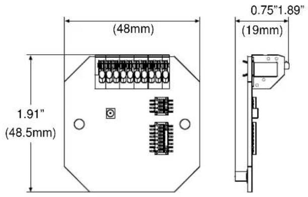
| Dimensions (W x H x D) 48 x 48 | 5 x 19 mm |
| Weight 15 g | |
PWS-4 / PWS-6
| PWS-4 PWS-6 | ||
| Supply Voltage (via PWS-C) 5 V DC | ||
| Supply Current (via PWS-C) 35 mA 30 mA | ||
| Max. Power Consumption 175 mW | 150 mW | |
| Buttons | 4 with green status LED2 Up/Down-Buttons | 6 with green status LED |
| LED chain | 4 green LEDs | - |
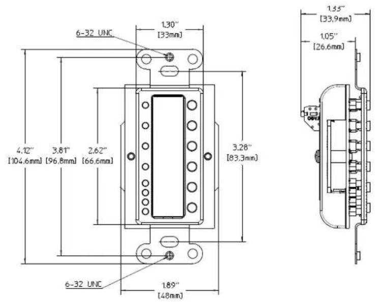
| Dimensions (W x H x D) | 48 x 105 x 34 mm | |
| Weight | 80 g | |
| Operating Temperature Range | -5 °C... 40 °C | |
6.1 Block Diagram
PWS-C
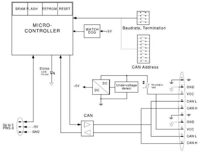
flowchart
graph TD
    A["SRAM FLASH EEPROM RESET"] --> B["MICRO-CONTROLLER"]
    B --> C["WATCH DOG"]
    C --> D["Baudrate, Termination"]
    D --> E["CAN Address"]
    E --> F["CAN"]
    F --> G["+5V"]
    G --> H["DC DC"]
    H --> I["Undervoltage detect"]
    I --> J["Resettable input"]
    J --> K["CAN L CAN H"]
    K --> L["GND VCC CAN L CAN H"]
    L --> M["Up to 3 PWS-X +5V GND"]
    M --> N["Status LED Yellow"]
    N --> B
6.2 Dimensions
PWS-C
PWS-4
PWS-6
![6-32 UNC 1.30" [33mm] 4.12" [104.6mm] 3.81" [96.8mm] 2.62" [66.6mm] 3.26" [83.3mm] 6-32 UNC 1.89" [48mm]](/content/2026/05/826000/images/f42b3f20dbdc77e5026372ce10ae1ffc3cce859fa29eca6383e8a1f1d66a0884.jpg)
![1.33" [33.9mm] 1.05" [26.6mm]](/content/2026/05/826000/images/a6e691efd8fc53552f8fdf12a5e21d705e3395821181ddf9dee4b444dbb1f253.jpg)
6.3 Declaration of Conformity
DECLARATION OF CONFORMITY
being solely responsible herfore declare that the product:
Geräteart / Type of Equipment : PROGRAMMABLE WALL STATION
Model / Type
: PWS-C
PWS-4
PWS-6
which is the subject of this declaration complies with the following standard(s) or normative document(s)
Technical Regulations:
+ Corrigendum July 2003
+ A1:2000
+ Corrigendum April 2003
+ A2:2003
EN 55024:1998
+ A1:2001
+ A2:2003
Straubing, 06.03.2007
Place and date of issue
G. Krauss
Legally binding signature
of the PERSON IN CHARGE
FCC Statement
This device complies with Part 15 of the FCC Rules. Operation is subject to the following two conditions: (1) this device may not cause harmful interference, and (2) this device must accept any interference received, including interference that may cause undesired operation.
ICES Statement
This Class B digital apparatus complies with Canadian ICES-003.
Telex Communications Inc.
12000 Portland Ave South,
Burnsville, MN 55337, USA
USA:
Phone:1-800-392-3497
Fax: 1-800-955-6831
Canada:
Phone: 1-866-505-5551
Fax:1-866-336-8467
Latin America:
Phone: 1-952-887-5532
Fax: 1-952-736-4212
Japan: EVI Audio Japan Ltd.
5-3-8 Funabashi
Setagaya-Ku
Tokyo
Japan 156-0055
Phone: +81 3-5316-5020
Fax: +81 3-5316-5031
China: Telex EVI Audio (Shanghai) Ltd.
Room 3105-3109
No. 1 Building
No. 218, Tian Mu West Road
Shanghai
China
PC: 200070
Phone: +86 21-6317-2155
Fax: +86 21-6317-3023
Europe, Africa & Middle-East
Germany: EVI Audio GmbH
Hirschberger Ring 45
D-94315 Straubing
Germany
Phone: +49 9421 706-0
Fax: +49 9421 706-265
Hong Kong: Telex EVI Audio (HK) Ltd.
Unit 5, 1/F,
Topsail Plaza 11 On Shum Street Shek Mun
Shatin
HK
Phone: +852 2351-3628
Fax: +852 2351-3329
France: EVI Audio France S.A.
Parc de Courcerin
Allée Lech Walesa
F 77185 Lognes
France
Phone: +33 1-6480-0090
Fax: +33 1-6006-5103
Singapore: Telex Pte. Ltd.
38C Jalan Pemimpin
Singapore 577180
Phone: (65) 6319 0621
Fax: (65) 6319 0620
UK: Shuttlesound
4 The Willows Centre
Willow Lane
Mitcham
Surrey CR4 4NX
UK
Phone: +44 208 646 7114
Fax: +44 208 254 5666

- INHALT
- IMPORTANT SAFETY INSTRUCTIONS
- IMPORTANT SERVICE INSTRUCTIONS
- Introduction
- Overview
- Applications
- IRIS-Net™
- CAN-Bus coupler PWS-C
- Front view:
- Rear view:
- Default settings:
- PWS Front Unit PWS-4/PWS-6
- PWS-4
- PWS-6
- Mounting and Configuration
- NOTE:
- Initial Operation
- Mounting a Programmable wall station in a US Single Gang Wall Box
- Hardware Configuration
- Baud Rate
- Determination of a suitable baud rate
- Setting the Baud Rate
- Setting a default baud rate in PROG mode
- Termination
- CAN address
- CAUTION:
- NOTES:
- CAN-Status-LED
- Connection
- Connecting the CAN-Bus
- Supply Voltage
- Power Rating Evaluation Example:
- Find Function
- Diagnostic Mode
- Automatic Configuration
- NOTE: If the to be replaced unit had been used in PROG-Mode with a baud rate unequal 10 kbit/s, the factory default baud rate of the new device needs to be set (see page 13).
- Firmware Update
- CAN-Bus Principles
- CAN-Bus Cabling Specifications
- General Note:
- Block Diagram
- Dimensions
- Declaration of Conformity
- DECLARATION OF CONFORMITY
- FCC Statement
- ICES Statement
- Europe, Africa & Middle-East
Brand : ELECTRO-VOICE
Model : PWS-4
Category : Uncategorized