
ISO-23 MKII - DJ Equipment Omnitronic - Free user manual and instructions
Find the device manual for free ISO-23 MKII Omnitronic in PDF.


| Product Type | 3-Band Frequency Isolator |
| Model | ISO-23 MKII |
| Brand | Omnitronic |
| Power Supply | 100-240 V AC, 50/60 Hz |
| Power Consumption | 12 W |
| Inputs | 2 x XLR (balanced), 2 x RCA (unbalanced) |
| Outputs | 2 x XLR (balanced), 2 x RCA (unbalanced) |
| Maximum Input Level | +22 dBu |
| Maximum Output Level | +22 dBu |
| Frequency Bands | Lows: 20 Hz - 300 Hz, Mids: 300 Hz - 4 kHz, Highs: 4 kHz - 20 kHz |
| Control Range | Kill to +9 dB |
| Potentiometers | Vintage ALPS RK27 (Blue Velvet) |
| Bypass Switch | Yes, with LED indicator |
| Overload Indicator | Yes |
| Kill Cut Feature | Yes, for each band |
| Rack Mountable | Yes, 1U (483 mm), mounting brackets included |
| Dimensions (W x D x H) | 483 x 145 x 44 mm |
| Weight | 1.7 kg |
| Operating Temperature Range | -5°C to +45°C |
| Relative Humidity (max) | 50% at 45°C |
| Safety Class | Class I |
| Cleaning | Use a soft, damp cloth; disconnect from mains |
| Fuse Replacement | Only replace with same type and rating |
| Spare Parts | Use genuine parts only |
Frequently Asked Questions - ISO-23 MKII Omnitronic
User questions about ISO-23 MKII Omnitronic
0 question about this device. Answer the ones you know or ask your own.
Ask a new question about this device
Download the instructions for your DJ Equipment in PDF format for free! Find your manual ISO-23 MKII - Omnitronic and take your electronic device back in hand. On this page are published all the documents necessary for the use of your device. ISO-23 MKII by Omnitronic.
USER MANUAL ISO-23 MKII Omnitronic
natural_image
Abstract 3D rendering of a stylized white ring with black center and blue-to-purple motion lines at bottom (no text or symbols)1 Introduction ...... 9
Product features ...... 9
2 Safety Instructions 10
3 Operating .... 11
Determinations .... 11
4 Operating Elements and Connections. 12
5 Setup .... 14
Installation .... 14
Cable connections .... 14
6 Cleaning and Maintenance 14
7 Technical Specifications .... 15
1 Introduction
With the ISO-23 MK2 frequency isolator DJs get an effective tool for creative sound shaping in the club or studio. Using high-grade components such as long-life ALPS RK27 potentiometers, the rack-mounted isolator has excellent sound characteristics.
The large, smooth rotary knobs enable DJs to radically boost or cut low, mid or high frequencies, making it easy to create instrumental or a cappella versions. The isolator provides XLR and RCA connectors and features a bypass switch for bridging.
This user manual will show you how to install and operate the isolator. Users of this product are recommended to carefully read all warnings in this manual and on the unit in order to protect yourself and others from damage.
This user manual is valid for item number: 10355903. Please save this document for future needs and pass it on to further owners.
Product features
- 3-band frequency isolator with dedicated boost and kill cut for DJs
- Kill cut feature enables DJs to completely remove low, mid and high frequencies for amazing mixing
- Vintage ALPS potentiometers (Blue Velvet RK27)
• High-grade components ensure long life and excellent sound quality
• 1-channel stereo version
• Control range: kill to +6 dB
• Lows: 20 Hz - 300 Hz
• Mids: 300 Hz - 4 kHz
• Highs: 4 kHz - 20 kHz - Bypass switch
• Balanced and unbalanced inputs/outputs (XLR/RCA) - Incl. mounting brackets for 483 mm rack installation (1 U)
For product updates, documentation, software and support please visit www.omnitronic.de. You can find the latest version of this user manual in the product's download section.
© 2019 OMNITRONIC. All rights reserved.
No part of this document may be reproduced in any form without the written permission of the copyright owner. The contents of this document are subject to revision without notice due to continued progress in methodology, design, and manufacturing.
All trademarks mentioned herein are the property of their respective owners.
2 Safety Instructions

Caution!
Keep this device away from rain and moisture!

Caution!
Be careful with your operations. With a dangerous voltage you can suffer a dangerous electric shock when touching the wires!
This device has left our premises in absolutely perfect condition. In order to maintain this condition and to ensure a safe operation, it is absolutely necessary for the user to follow the safety instructions and warning notes written in this user manual. Damages caused by the disregard of this user manual are not subject to warranty. The dealer will not accept liability for any resulting defects or problems.
Unpacking
- Please make sure that there are no obvious transport damages. Should you notice any damages, do not take the device into operation and immediately consult your local dealer.
- Save the package and all packing materials. In the event that a fixture must be returned to the factory, it is important that the fixture be returned in the original factory box and packing.
Protection Class
- This device falls under protection class I. The power plug must only be plugged into a protection class I outlet. The voltage and frequency must exactly be the same as stated on the device. Wrong voltages or power outlets can lead to the destruction of the device and to mortal electrical shock.
Power Cord
- Always plug in the power plug least. The power plug must always be inserted without force. Make sure that the plug is tightly connected with the outlet.
- Never let the power cord come into contact with other cables! Handle the power cord and all connections with the mains with particular caution! Never touch them with wet hands, as this could lead to mortal electrical shock.
- Never modify, bend, strain mechanically, put pressure on, pull or heat up the power cord. Never operate next to sources of heat or cold. Disregard can lead to power cord damages, fire or mortal electrical shock.
- The cable insert or the female part in the device must never be strained. There must always be sufficient cable to the device. Otherwise, the cable may be damaged which may lead to mortal damage.
- Make sure that the power cord is never crimped or damaged by sharp edges. Check the device and the power cord from time to time.
- If extension cords are used, make sure that the core diameter is sufficient for the required power consumption of the device. All warnings concerning the power cords are also valid for possible extension cords.
- Always disconnect from the mains, when the device is not in use or before cleaning it. Only handle the power cord by the plug. Never pull out the plug by tugging the power cord. Otherwise, the cable or plug can be damaged leading to mortal electrical shock. If the power plug or the power switch is not accessible, the device must be disconnected via the mains.
- If the power plug or the device is dusty, the device must be taken out of operation, disconnected and then be cleaned with a dry cloth. Dust can reduce the insulation which may lead to mortal electrical shock. More severe dirt in and at the device should only be removed by a specialist.
Liquids
- There must never enter any liquid into power outlets, extension cords or any holes in the housing of the device. If you suppose that also a minimal amount of liquid may have entered the device, it must immediately be disconnected. This is also valid, if the device was exposed to high humidity. Also if the device is still running, the device must be checked by a specialist if the liquid has reduced any insulation. Reduced insulation can cause mortal electrical shock.
Foreign Objects
- There must never be any objects entering into the device. This is especially valid for metal parts. If any metal parts like staples or coarse metal chips enter into the device, the device must be taken out of operation and disconnected immediately. Malfunction or short-circuits caused by metal parts may cause mortal injuries.
3 Operating Determinations
This 3-band frequency isolator is used for tone adjustment of line signal sources. It has been specially designed for professional applications.
Power Supply
- Only connect the device to a properly installed mains outlet. The outlet must be protected by residual current breaker (RCD). The voltage and frequency must exactly be the same as stated on the device. If the mains cable is equipped with an earthing contact, then it must be connected to an outlet with a protective ground. Never deactivate the protective ground of a mains cable. Failure to do so could possibly injure the user.
Installation
- Do not shake the device. Avoid brute force when installing or operating the device. When choosing the installation spot, please make sure that the device is not exposed to extreme heat, moisture or dust. There should not be any cables lying around. You endanger your own and the safety of others!
Taking into Operation
- Operate the device only after having familiarized with its functions. Do not permit operation by persons not qualified for operating the device. Most damages are the result of unprofessional operation!
Ambient Conditions
- The ambient temperature must always be between -5^ C and +45^ C. Keep away from direct insulation (particularly in cars) and heaters. The relative humidity must not exceed 50 % with an ambient temperature of 45^ C.
- This device must only be operated in an altitude between -20 and 2000 m over NN.
- Never use the device during thunderstorms. Over voltage could destroy the device. Always disconnect the device during thunderstorms.
- This device must never be operated or stockpiled in surroundings where splash water, rain, moisture or fog may harm the device. Moisture or very high humidity can reduce the insulation and lead to mortal electrical shocks.
- When using smoke machines, make sure that the device is never exposed to the direct smoke jet and is installed in a distance of 0.5 meters between smoke machine and device.
Transport
- Please use the original packaging if the device is to be transported.
Cleaning and Service
- Disconnect from mains before cleaning! Never use solvents or aggressive detergents in order to clean the device! Rather use a soft and damp cloth.
- There are no serviceable parts inside the device except for the fuse. Maintenance and service operations are only to be carried out by authorized dealers! Should you need any spare parts, please use genuine parts.
Modifications and Guarantee
- Please consider that unauthorized modifications on the speaker system are forbidden due to safety reasons!
- If this device will be operated in any way different to the one described in this manual, the product may suffer damages and the guarantee becomes void. Furthermore, any other operation may lead to dangers like short-circuit, burns, electric shock, etc.
WEEE Directive

If the unit is to be put out of operation definitively, take it to a local recycling plant for a disposal which is not harmful to the environment. Do not dispose of as municipal waste. Contact your retailer or local authorities for more information.
4 Operating Elements and Connections
Front panel

| No. | Element Function | |
| 1 | Mounting brackets Delivery includes mounting brackets for 19" (483 mm) rack installation. Fix the brackets at the left and right side of the housing. | |
| 2 | Overload indicator This indicator | lights up in case of an overload input signal. If it lights permanently, reduce the level of the signal source. |
| 3 | Bypass switch with indicator | When the switch is depressed the tone controls are bridged. The LED next to the switch lights up as a control. |
| 4 | Bass control | This control boosts and cuts frequencies in the bass range (20 Hz to 300 Hz). To boost the frequency range, turn the control clockwise; to attenuate, turn the control counterclockwise. When in center position (0 dB), the signal is not processed at all. Cutting the bass range can be used to create a cappella effects. |
| 5 | Mid control | This control boosts and cuts frequencies in the middle range (300 Hz to 4 kHz). To boost the frequency range, turn the control clockwise; to attenuate, turn the control counterclockwise. When in center position (0 dB), the signal is not processed at all. The midrange can be used to cut vocals and melody from the source material allowing you to create instrumentals. |
| 6 | High control | This control boosts and cuts frequencies in the high range (4 kHz to 20 kHz). To boost the frequency range, turn the control clockwise; to attenuate, turn the control counterclockwise. When in center position (0 dB), the signal is not processed at all. The high range can be used to emphasize the sound of the cymbals or hi-hats giving the sound material more presence and clarity. |
| 7 | Power switch with indicator | Turns power to the unit on and off. When powered on, the indicator lights up. |
Rear panel
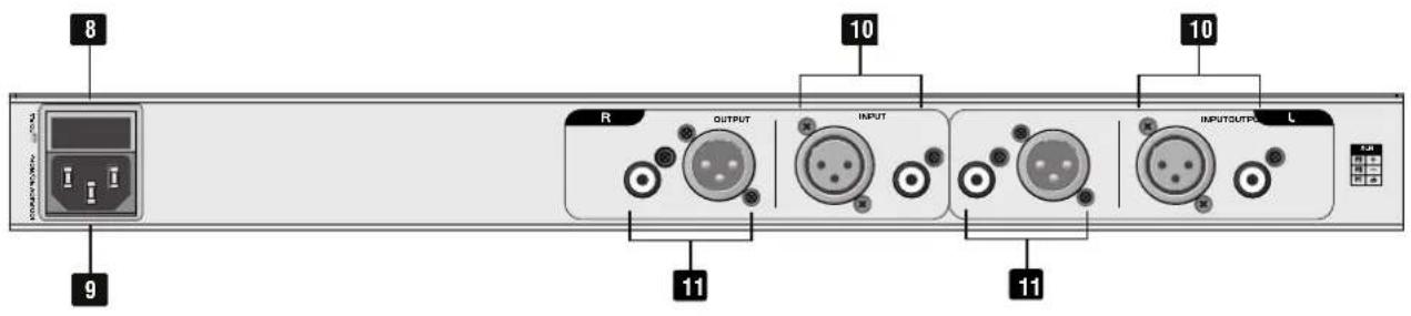
| No. | Element Function | |
| 8 | Fuse holder Only replace the fuse | when the device is disconnected from mains.Only use fuses of the same rating and power. The correct fuse value is specified on the rear panel. |
| 9 | Power input | Use the included power cable to connect this input to a power outlet. input. |
| 10 | Line inputs Balanced XLR and un | balanced RCA jacks for connecting the signal source. Use standard XLR or RCA cables to connect these inputs to e.g. a mixer or preamplifier. |
| 11 | Line outputs Balanced XLR and | unbalanced RCA jacks for connecting subsequent units. Use standard XLR or RCA cables to connect these outputs to e.g. a PA amplifier. |
5 Setup
Installation
The isolator can be used as a tabletop unit or installed in a 19" (483 mm) rack using the mounting brackets provided. For rack installation, screw on the brackets at the left and right side of the housing; then fix the unit with four M6 screws in the rack. A height of 1 unit is required. Please make sure that there is enough space around the device so that the heated air can be passed on. Steady overheating will damage your device.
Cable connections
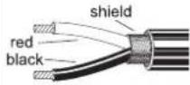
The isolator can be inserted as required, e. g. between preamplifier and power amplifier, between mixer and power amplifier or into an effect way of a mixer. The inputs and outputs can be connected both balanced via XLR plugs and unbalanced via RCA plugs. Balanced cables provide +6 dB more output and guarantee a better protection against interference in case of long cable runs. Be sure to use only high-grade cables. The illustrations below show the wiring of these cables.
| Connector Structure Balanced | connection | Unbalanced connection | |||||
XLR, male.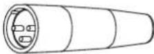 |  | plug side | 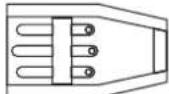 | cable side |  | red = 2black = 3shield = 1 | |
XLR, female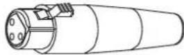 |  | plug side | 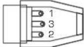 | cable side |  | red = 2black = 3shield = 1 | |
RCA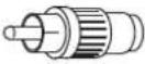 |  | red = tipblack = sleeveshield = n/c | |||||
 | |||||||
6 Cleaning and Maintenance
Disconnect from mains before starting maintenance operation! We recommend a frequent cleaning of the device. Please use a soft lint-free and moistened cloth. Never use alcohol or solvents!
There are no serviceable parts inside the device except for the fuse. Maintenance and service operations are only to be carried out by authorized dealers.
If the fine-wire fuse of the device fuses, only replace the fuse by a fuse of same type and rating. Before replacing the fuse, unplug mains lead.
Should you need any spare parts, please use genuine parts. If the power supply cable of this device becomes damaged, it has to be replaced by a special power supply cable available at your dealer.
Should you have further questions, please contact your dealer.
7 Technical Specifications
| ISO-23 MK2 | |
| Power supply: 100-240 V AC, 50/60 Hz | |
| Power consumption: 12 W | |
| Inputs: 2 x XLR, balanced | |
| 2 x RCA, unbalanced | |
| Maximum input level: +22 dBu | |
| Outputs: 2 x XLR, balanced | |
| 2 x RCA, unbalanced | |
| Maximum output level: +22 dBu | |
| Lows: 20 Hz - 300 Hz | |
| Mids: 300 Hz - 4 kHz | |
| Highs: 4 kHz - 20 kHz | |
| Control range: -- to +9 dB | |
| Dimensions (W x D x H): 483 x 145 x 44 mm | |
| Weight: 1.7 kg | |
Specifications are subject to change without notice due to product improvements.
© OMNITRONIC 2019
D00121971
Version 1.0
Omnitronic is a brand of Steinigke Showtechnic GmbH
- Introduction
- Product features
- Safety Instructions
- Caution!
- Unpacking
- Protection Class
- Power Cord
- Liquids
- Foreign Objects
- Operating Determinations
- Power Supply
- Installation
- Taking into Operation
- Ambient Conditions
- Transport
- Cleaning and Service
- Modifications and Guarantee
- WEEE Directive
- Operating Elements and Connections
- Setup
- Cable connections
- Cleaning and Maintenance
- Technical Specifications
Brand : Omnitronic
Model : ISO-23 MKII
Category : DJ Equipment