
17ZR - Coaxial cable TECHNISAT - Free user manual and instructions
Find the device manual for free 17ZR TECHNISAT in PDF.


| Product Type | Intermediate Amplifier (Active Branch Distributor) |
| Model | 17ZR (Article No. 0000/3269) |
| Application | Compensates cable and component damping up to 13 dB at 2150 MHz in large installations |
| Frequency Range (Terrestrial) | 47 – 862 MHz |
| Frequency Range (Satellite) | 0.95 – 2.15 GHz |
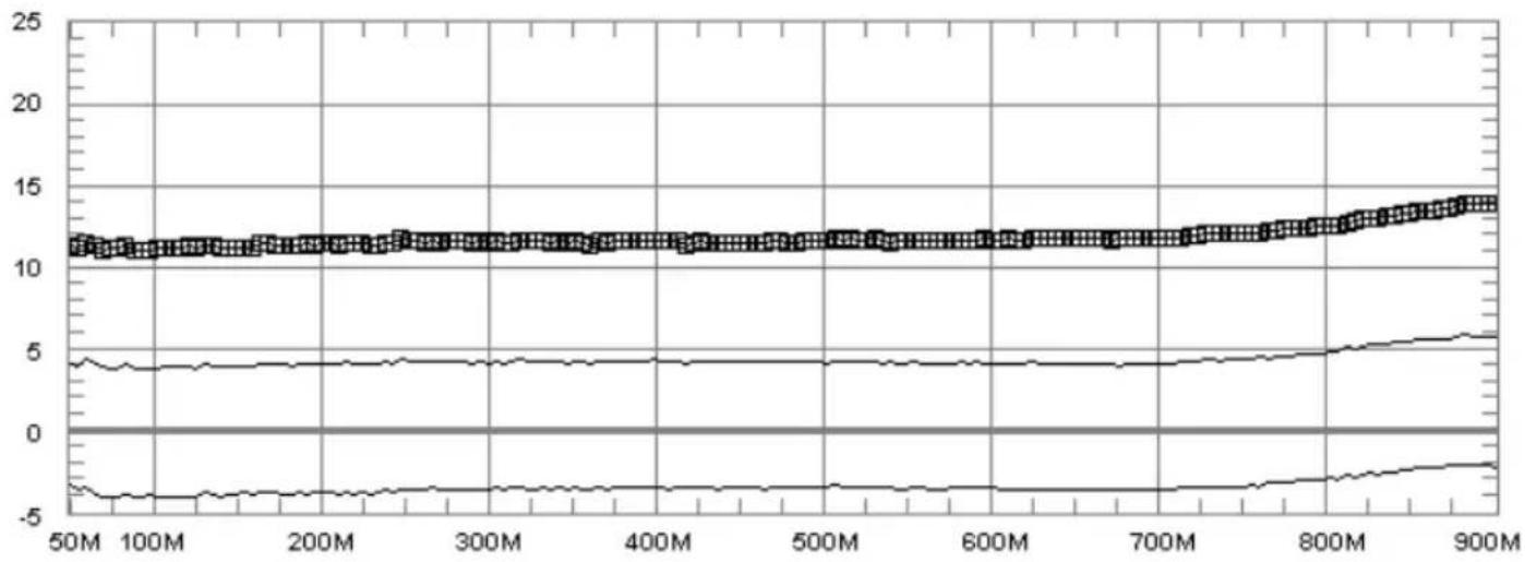
| Trunk Line Gain (Terrestrial) | 5 – 10 dB, adjustable |
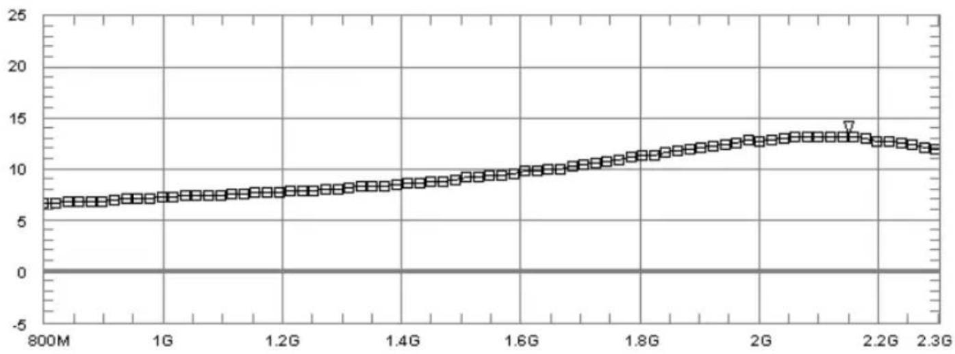
| Trunk Line Gain (Satellite) | 7 – 12 dB |
| Tap Gain (Terrestrial) | 5 dB, adjustable |
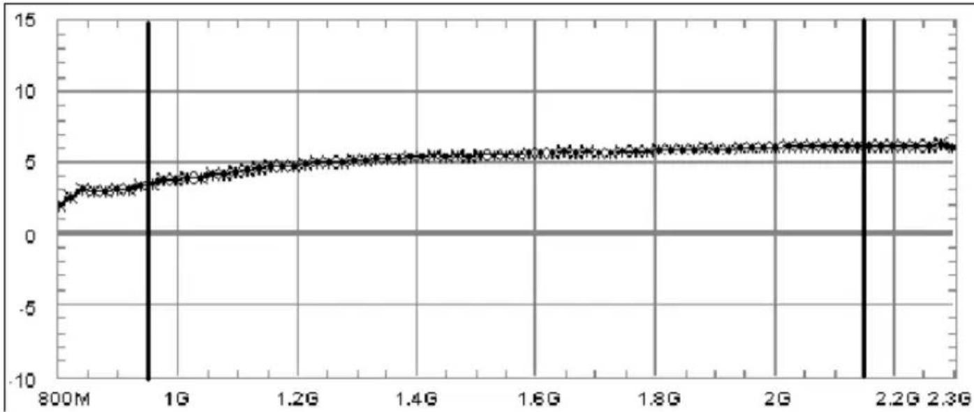
| Tap Gain (Satellite) | 3 – 6 dB |
| Slope Correction (Terrestrial) | Fixed correction included |
| Return Loss (Trunks) | 10 dB |
| Return Loss (Taps) | 14 dB |
| Isolation (Trunks) | 40 dB |
| Isolation (Taps) | 50 dB, widely cascadable |
| Return Path Loss (Trunks, 5–30 MHz) | 1.5 dB |
| Recommended Input Level (Terrestrial) | 58 dBμV |
| Maximum Input Level (Terrestrial) | 70 dBμV |
| Power Supply | Via trunk lines (DC, 13V/18V) |
| DC Resistance (Unit) | < 50 mOhm |
| Power Consumption | 180 mA at 18V, 120 mA at 13V |
| Dimensions (L x W x H) | 212 x 58 x 45 mm |
| Weight | 0.7 kg |
| Ambient Temperature | -25°C to +55°C |
| Overvoltage Protection | Inputs/outputs < 5 kV |
| Screening Level | Compliant with EN50083-2/A1 and TechniSelect S |
| Mounting | Indoor, dry rooms, non-flammable surface |
| Certifications | CE |
| Manual Languages | English, German (PDF available) |
Frequently Asked Questions - 17ZR TECHNISAT
User questions about 17ZR TECHNISAT
0 question about this device. Answer the ones you know or ask your own.
Ask a new question about this device
Download the instructions for your Coaxial cable in PDF format for free! Find your manual 17ZR - TECHNISAT and take your electronic device back in hand. On this page are published all the documents necessary for the use of your device. 17ZR by TECHNISAT.
USER MANUAL 17ZR TECHNISAT
Passiver Verteiler / Passive distributor 17PR
Zwischenverstärker / Intermediate amplifier 17ZR
Aktiver Abzweiger / Active Branch distributor 17/2AR
Montageanleitung
Installation instructions
Weitere Informationen unter: www.technisat.de Additional information can be found at: www.technisat.de

Inhalt
line
| X | Y | |-------|------| | 50M | 0.0 | | 200M | 0.0 | | 300M | 0.0 | | 400M | 0.0 | | 500M | 0.0 | | 600M | 0.0 | | 700M | 0.0 | | 800M | 0.0 | | 900M | 0.0 |1 Application
2 Safety notes
3 Intermediate amplifier 17ZR
4 Active branch distributor 17/2AR
5 Passive distributor 17PR
6 Examples of installations
7 Technical data
8 Calculation hints
1 Application
With these devices you can implement installations for up to 1000 participants, all are fed from the same external unit. Fundamental explanations can be found in the installation instructions for the GigaSystem 17/8G and K.
In all these accessories units the return channel signals are transmitted to the CMTS (Cable Modem Termination System) in a linear frequency, passive, low-dam-ping mode. In the process, the terrestrial system is operated as an active one.
In conjunction with suitable headend- and participant- technology, this enables the provision of fast Internet access, VoIP, and voting options – all without the need for additional cables to be installed.
Such applications are only cost-effective in large installations.
2 Safety instructions
For your own protection, please read the safety notes carefully before installation.
The manufacturer assumes no responsibility for accidents resulting from or associated with inappropriate handling of system or by non-compliance with the safety precautions.
The components must be installed in dry rooms on level surfaces that are non-flammable.
Do not cover the ventilations slots of the components.
Do not install the units in roof insulation material.
Install the equipment while it is not connected to the power line.
Ensure that the antenna installation is grounded.
The antenna equipment must be protected against lightning in accordance with local regulations.
All relevant European standards and VDE regulations concerning electrical safety must be complied with.
National regulations regarding the licensing of wireless reception equipment must be considered.
Do not under any circumstances open the housing of the product.
If it becomes necessary to open a unit, only trained specialist personnel should perform this. Disconnect unit from the power supply and call a specialist in the following cases:
The unit was exposed to high levels of humidity, or liquid has run into the unit,
In case of malfunctions,
In case of significant external damage.
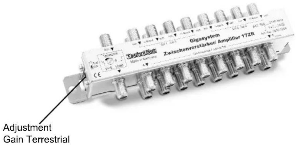
3 Intermediate amplifier 17ZR (Art. No. 0000/3269)
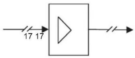
The amplification levels as well as the fixed slope rectification of this unit are specifically designed to compensate the damping caused by cables and/or components of maximum 13dB at 2150MHz.
The unit should be used when the level has already dropped a little.
It combines all horizontal and vertical trunk lines with each other by means of direct current (except SAT1, High Band), so that the DC-resistance of individual trunk lines is decreased. The amplification of the terrestrial path is adjustable.
flowchart
graph LR
    A["17"] --> B["△"]
    C["17"] --> B
    B --> D["→"]
Gain satellite frequency range
line
| x | y | |-------|-----| | 800M | 7 | | 1G | 7 | | 1.2G | 8 | | 1.4G | 9 | | 1.6G | 10 | | 1.8G | 11 | | 2G | 12 | | 2.2G | 13 | | 2.3G | 12 |Gain terrestrial
line
| X | Series 1 | Series 2 | Series 3 | Series 4 | |-------|----------|----------|----------|----------| | 50M | 11.5 | 4.0 | -3.0 | 11.5 | | 100M | 11.5 | 4.0 | -3.0 | 11.5 | | 200M | 11.5 | 4.0 | -3.0 | 11.5 | | 300M | 11.5 | 4.0 | -3.0 | 11.5 | | 400M | 11.5 | 4.0 | -3.0 | 11.5 | | 500M | 11.5 | 4.0 | -3.0 | 11.5 | | 600M | 11.5 | 4.0 | -3.0 | 11.5 | | 700M | 12.0 | 4.5 | -2.5 | 12.0 | | 800M | 12.5 | 5.0 | -2.0 | 12.5 | | 900M | 13.5 | 6.0 | -1.5 | 13.5 |
4 Active branch distributor 17/2AR (Art.-No. 0000 / 3270)
The active branch distributor 17/2AR is a component of the GigaSystem 17/X.
It serves to provide low-loss branching of signals from trunk lines.
It can be cascaded up to 6 times to provide signals for the sub-distribution nodes on the different floors of a multi-storey building, or to neighbouring houses in a row of houses.
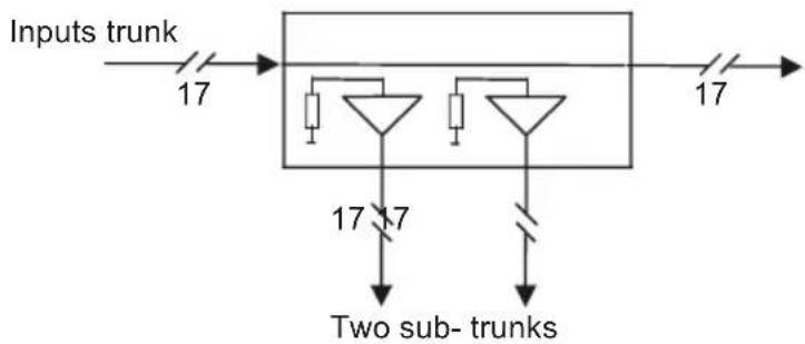
Use multi-media cable for the trunk lines. The amplification provided by the units is suitable for practical applications, and provides narrow tolerances. The trunks consist of (passive) directional couplers with very low attenuation. This fact, as well as outstanding isolation, ensures that up to 6 units 17/2AR can be cascaded To compensate for the attenuation resulting from the cable used, please use one or more intermediate amplifiers 17ZR.
The device itself is fed with DC voltage from both sub-trunks 1 (the taps), but it does not feed the (main)-trunks. To feed matrices, amplifiers and LNB's in the (main)-trunk, you must connect a 17/8G unit to the trunk output of the last 17/2AR.
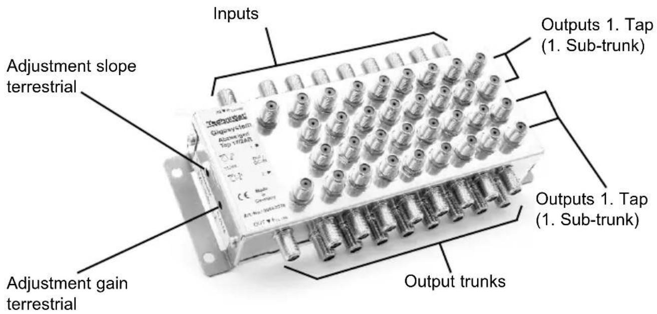
If the terrestrial amplification is to be reduced in a linear manner, use the attenuation adjustment control. Additionally a slope adjustment is implemented.
To ensure reliable function with reserve capacity in larger installations, it is essential to calculate levels, isolation, voltage drops and the power loads of supplies before proceeding with the installation.
An example of this is shown in chapter 6.1. The data can be found in the technical specifications and chapter 8 below.
flowchart
graph TD
    A["Inputs trunk"] --> B["Block"]
    B --> C["Two sub-trunks"]
    B --> D["Output 17"]
    B --> E["Output 17"]
    B --> F["Output 17"]
Trunk loss satellite frequency range
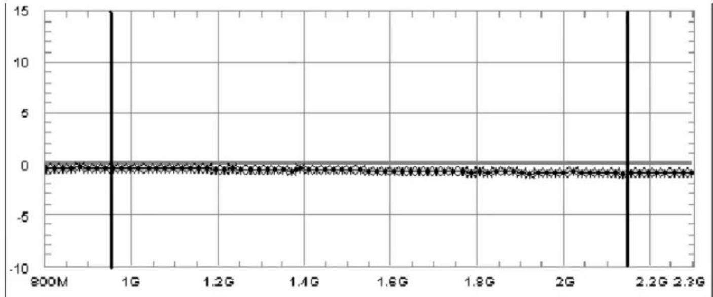
line
| X | Y | |-------|------| | 800M | 0.0 | | 1G | 0.0 | | 1.2G | 0.0 | | 1.4G | 0.0 | | 1.6G | 0.0 | | 1.8G | 0.0 | | 2G | 0.0 | | 2.2G | 0.0 | | 2.3G | 0.0 |Trunk loss terrestrial
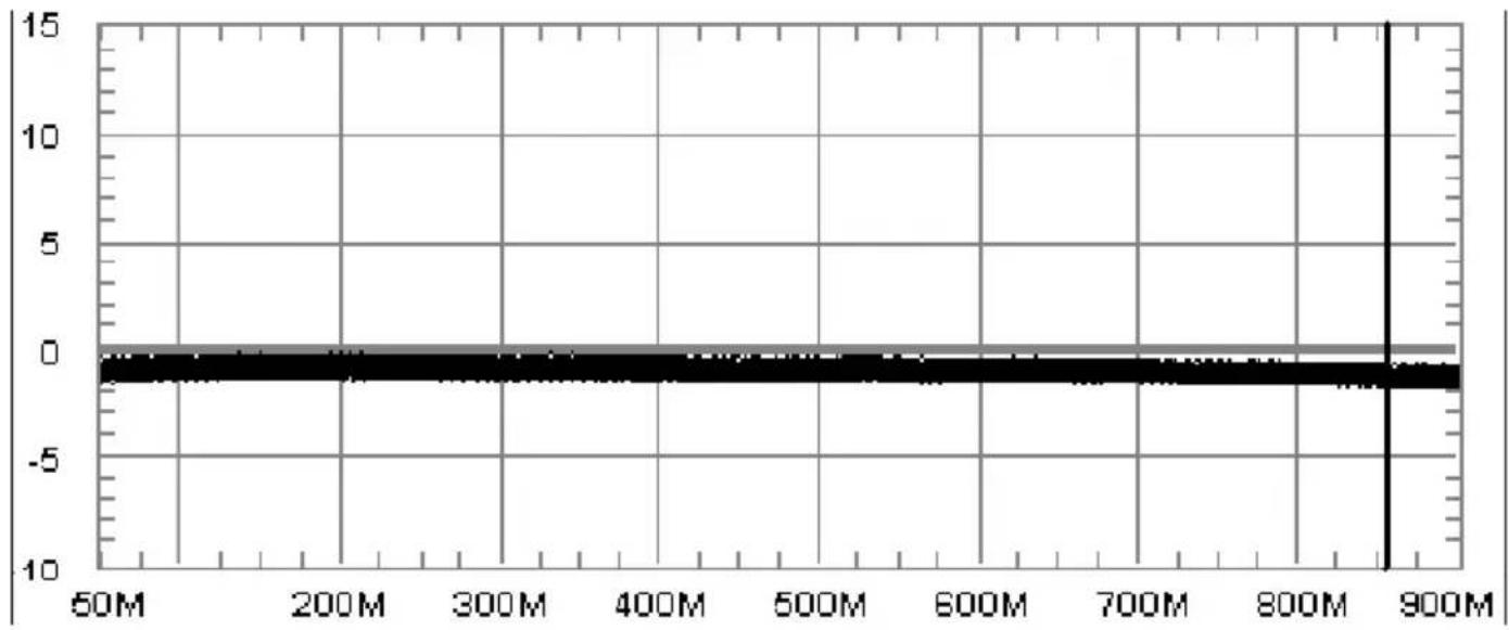
line
| X | Y | |-------|------| | 50M | 0.0 | | 200M | 0.0 | | 300M | 0.0 | | 400M | 0.0 | | 500M | 0.0 | | 600M | 0.0 | | 700M | 0.0 | | 800M | 0.0 | | 900M | 0.0 |Tap (sub-trunk) gain satellite frequency range
line
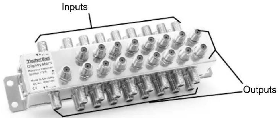
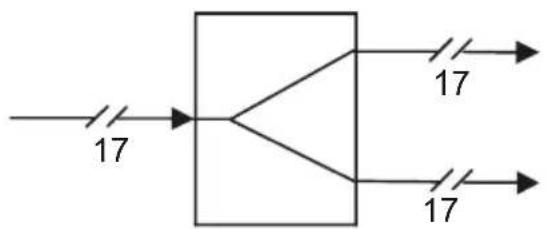
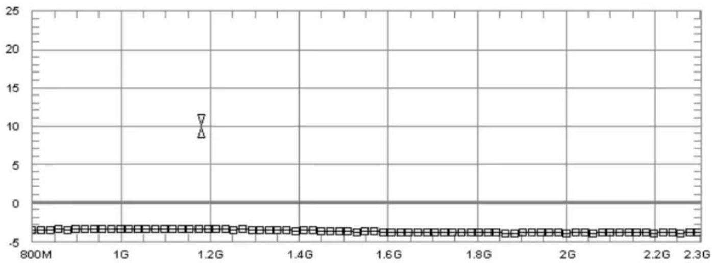
| Time | Value | |------|-------| | 800M | ~2.5 | | 1G | ~3.5 | | 1.2G | ~4.5 | | 1.4G | ~5.0 | | 1.6G | ~5.5 | | 1.8G | ~6.0 | | 2G | ~6.5 | | 2.2G | ~7.0 | | 2.3G | ~7.5 |This device has a maximum loss of 4dB and distributes the signals of the 16 satellite IF planes and of the terrestrial path to two outputs. The upper output provides direct current decoupling in order to prevent any mutual interference by the power supplies feeding in current.

flowchart
graph LR
    A["17"] --> B["Process Block"]
    B --> C["17"]
    B --> D["17"]
Loss satellite frequency range
scatter
| x | y | |-------|------| | 1.2G | 9.0 |Loss terrestrial
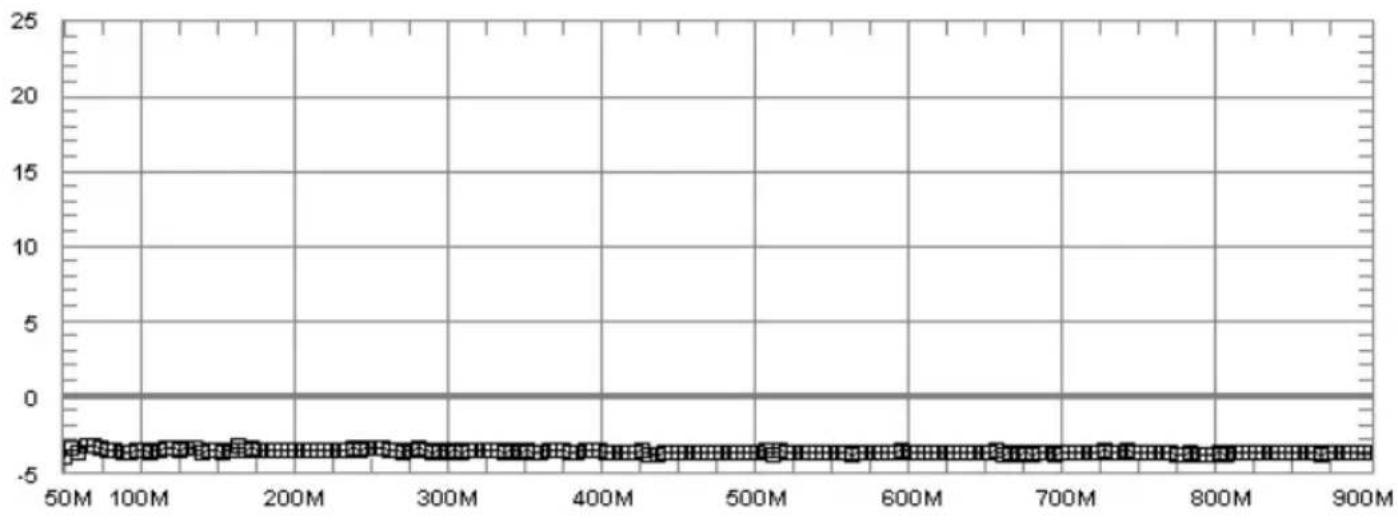
line
| x | y | |-------|------| | 50M | -3.0 | | 100M | -2.8 | | 200M | -2.6 | | 300M | -2.4 | | 400M | -2.2 | | 500M | -2.0 | | 600M | -1.8 | | 700M | -1.6 | | 800M | -1.4 | | 900M | -1.2 |6 Examples of installations
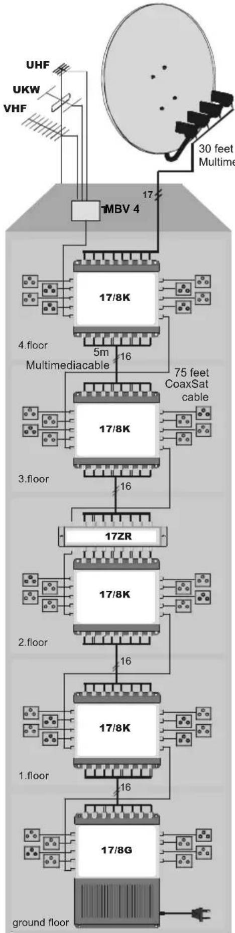
Apartment building with 40 participants on 5 floors
flowchart
graph TD
    A["30 feet Multime"] --> B["MBV 4"]
    B --> C["17/8K"]
    C --> D["4.floor Multimediacable"]
    D --> E["5m"]
    E --> F["16"]
    F --> G["17/8K"]
    G --> H["3.floor"]
    H --> I["16"]
    I --> J["17ZR"]
    J --> K["17/8K"]
    K --> L["2.floor"]
    L --> M["16"]
    M --> N["17/8K"]
    N --> O["1.floor"]
    O --> P["17/8G"]
    P --> Q["ground floor"]
    style A fill:#f9f,stroke:#333
    style Q fill:#ccf,stroke:#333
Calculation of range of coverage:
- cascade with distribution by floors
- example for sub distribution in longer installations
(in this case you need to use 17/2A instead of the LNB's)
| level isolation voltage current | |||
| @2,15 GHz (dB) | (V) on the spot (mA) | ||
| LNB 70 45 17,2 800 | |||
| 17/8K-input | 62 | 45^1) | 17,3 930 | |
| socket 54 | 35 |
| 17/8K-input | 56 42 | 17,4 | 1060 | |
| socket 48 | 35 |
| 17ZR | 54 38 | 17,5 | 1370 | 1240 |
| 17/8K | 67 | 37 17,6 | 1370 | |
| socket 59 | 33 |
| 17/8K-input | 61 36 | 17,8 | 1500 | |
| socket 53 | 32 |
| 17/8K-input | 55 35 | 18V | 1570 |
| socket 47 | 32 | 2) |
1) Isolation of the 17/8K, for calculation purposes without consideration of the LNB's
Together with the 25dB of the LNB's at best there will be arising approx. 24dB isolation. If you add two 17/2AR and one 17ZR in a longer installation (see 6.2), the isolation decrease to worst ca30dB (
=> That's just enough to operate.
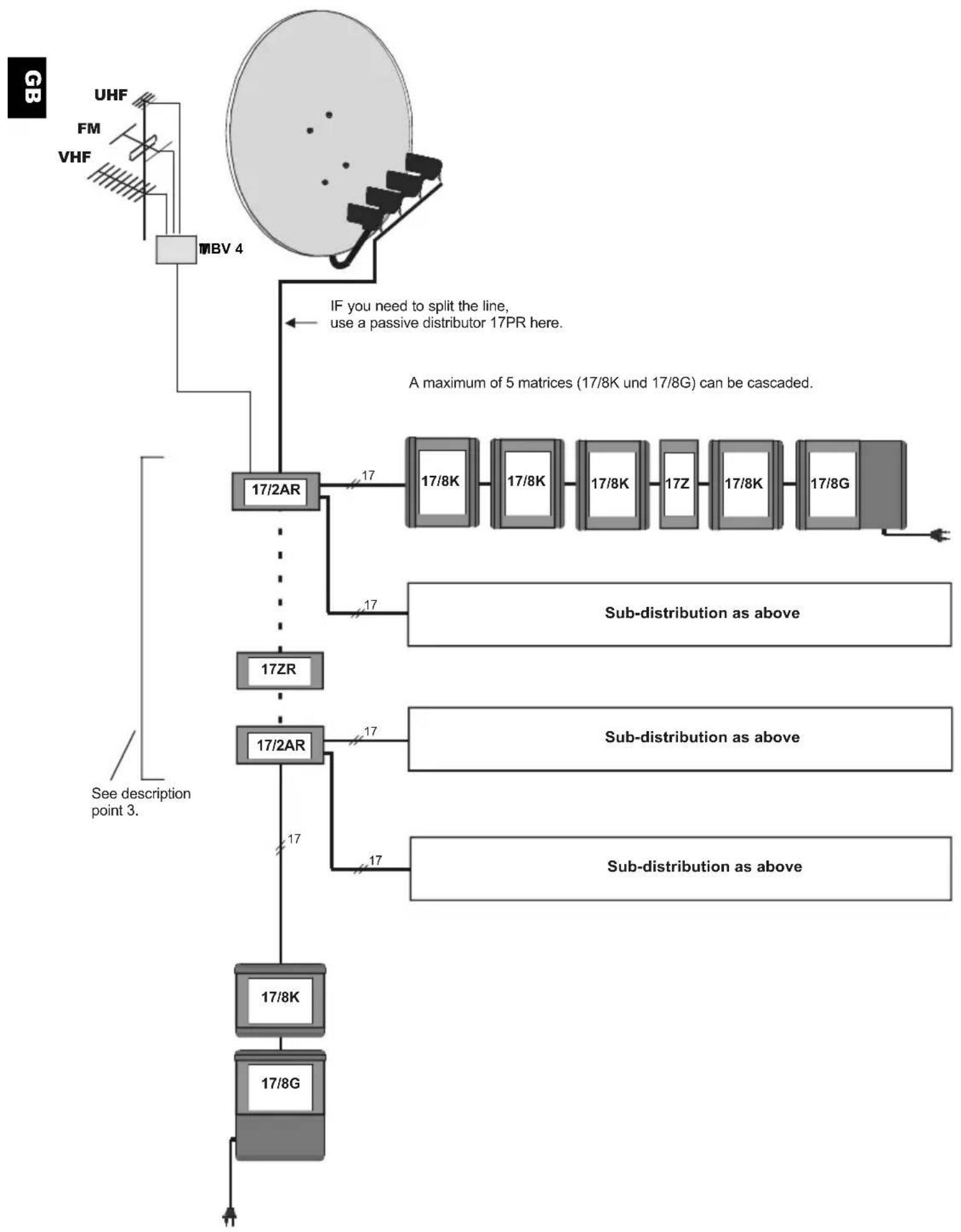
Installation utilizing a line
flowchart
graph TD
    A["UHF"] --> B["FB"]
    C["FM"] --> B
    D["VHF"] --> B
    E["MBV 4"] --> B
    B --> F["17/2AR"]
    F --> G["17/8K"]
    F --> H["17/8K"]
    F --> I["17/8K"]
    F --> J["17Z"]
    F --> K["17/8K"]
    F --> L["17/8G"]
    M["A maximum of 5 matrices (17/8K und 17/8G) can be cascaded."] --> N["Sub-distribution as above"]
    O["See description point 3."] --> P["17ZR"]
    Q["17/2AR"] --> R["17/8K"]
    Q --> S["17/8G"]
    T["17/2AR"] --> U["17/8K"]
    T --> V["17/8G"]
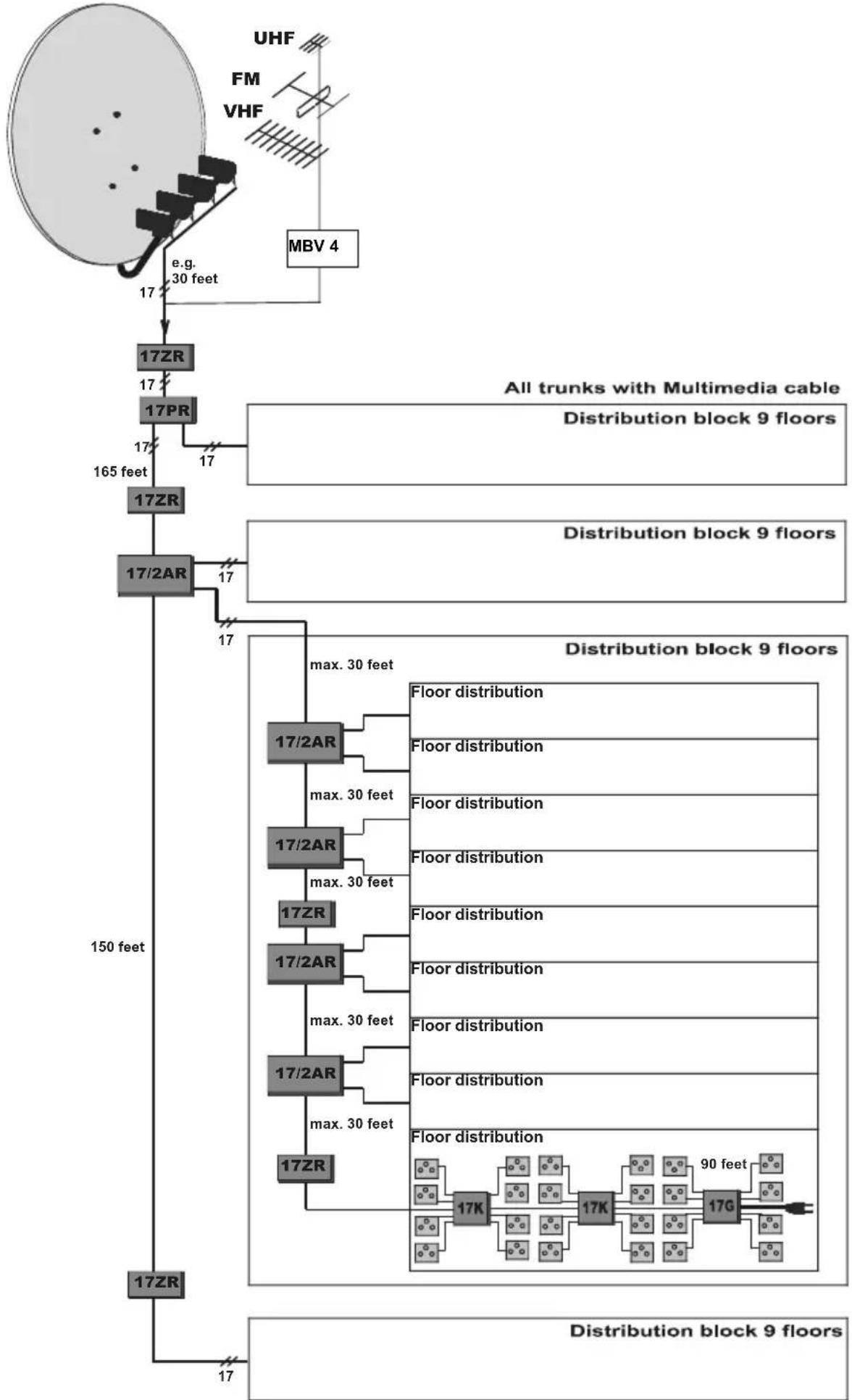
Installation in high-rise buildings
(24 participants/floor, 864 participants in total combined, 138 components)
flowchart
graph TD
    A["17ZR"] -->|e.g. 30 feet| B["17ZR"]
    B --> C["17PR"]
    C --> D["17ZR"]
    D --> E["17/2AR"]
    E --> F["17ZR"]
    F --> G["17ZR"]
    G --> H["17ZR"]
    H --> I["17ZR"]

    subgraph "All trunks with Multimedia cable"
        J["Distribution block 9 floors"]
        K["Distribution block 9 floors"]
    end

    subgraph "Distribution block 9 floors"
        L["Floor distribution"]
        M["Floor distribution"]
        N["Floor distribution"]
        O["Floor distribution"]
        P["Floor distribution"]
        Q["Floor distribution"]
        R["Floor distribution"]
        S["Floor distribution"]
        T["Floor distribution"]
        U["Floor distribution"]
        V["Floor distribution"]
        W["Floor distribution"]
        X["Floor distribution"]
        Y["Floor distribution"]
        Z["Floor distribution"]
        AA["Floor distribution"]
        AB["Floor distribution"]
        AC["Floor distribution"]
        AD["Floor distribution"]
        AE["Floor distribution"]
        AF["Floor distribution"]
        AG["Floor distribution"]
        AH["Floor distribution"]
        AI["Floor distribution"]
        AJ["Floor distribution"]
        AK["Floor distribution"]
        AL["Floor distribution"]
        AM["Floor distribution"]
        AN["Floor distribution"]
        AO["Floor distribution"]
        AP["Floor distribution"]
        AQ["Floor distribution"]
        AR["Floor distribution"]
        AS["Floor distribution"]
        AT["Floor distribution"]
        AU["Floor distribution"]
        AV["Floor distribution"]
        AW["Floor distribution"]
        AX["Floor distribution"]
        AY["Floor distribution"]
        AZ["Floor distribution"]
        BA["Floor distribution"]
        BB["Floor distribution"]
        BC["Floor distribution"]
        BD["Floor distribution"]
        BE["Floor distribution"]
        BF["Floor distribution"]
        BG["Floor distribution"]
        BH["Floor distribution"]
        BI["Floor distribution"]
        BJ["Floor distribution"]
        BK["Floor distribution"]
        BL["Floor distribution"]
        BM["Floor distribution"]
    end

    style A fill:#f9f,stroke:#333
    style B fill:#f9f,stroke:#333
    style C fill:#f9f,stroke:#333
    style D fill:#f9f,stroke:#333
    style E fill:#f9f,stroke:#333
    style F fill:#f9f,stroke:#333
    style G fill:#f9f,stroke:#333
    style H fill:#f9f,stroke:#333
    style I fill:#f9f,stroke:#333
    style J fill:#f9f,stroke:#333
    style K fill:#f9f,stroke:#333
    style L fill:#f9f,stroke:#333
    style M fill:#f9f,stroke:#333
    style N fill:#f9f,stroke:#333
    style O fill:#f9f,stroke:#333
    style P fill:#f9f,stroke:#333
    style Q fill:#f9f,stroke:#333
    style R fill:#f9f,stroke:#333
    style S fill:#f9f,stroke:#333
    style T fill:#f9f,stroke:#333
    style U fill:#f9f,stroke:#333
    style V fill:#f9f,stroke:#333
    style W fill:#f9f,stroke:#333
    style X fill:#f9f,stroke:#333
    style Y fill:#f9f,stroke:#333
    style Z fill:#f9f,stroke:#333
    style AA fill:#f9f,stroke:#333
    style AB fill:#f9f,stroke:#333
    style AC fill:#f9f,stroke:#333
    style AD fill:#f9f,stroke:#333
    style AE fill:#f9f,stroke:#333
    style AF fill:#f9f,stroke:#333
    style AG fill:#f9f,stroke:#333
    style AH fill:#f9f,stroke:#333
    style AI fill:#f9f,stroke:#333
    style AJ fill:#f9f,stroke:#333
    style AK fill:#f9f,stroke:#333
    style AL fill:#f9f,stroke:#333
    style AM fill:#f9f,stroke:#333
    style AN fill:#f9f,stroke:#333
    style AO fill:#f9f,stroke:#333
    style AP fill:#f9f,stroke:#333
    style AQ fill:#f9f,stroke:#333
    style AR fill:#f9f,stroke:#333
    style AS fill:#f9f,stroke:#333
    style AT fill:#f9f,stroke:#333
7 Technical data accessories to GigaSystem 17 / X, guaranteed parameters
| Terr:47..862MHz,Sat:0,95..2,15GHz | Intermediate amplifier 17ZR | Active branch dis-tributor 17/2AR | Passive distributor 17PR | |||
| Application | Amplification,when the level is reduced | spared branching of two side trunks signal splitting | ||||
| Terr:47..862GHz,Sat:0,95..2,15GHz | Terr. Sat. | Terr. Sat. T | err. | Sat. | ||
| Trunk line gain | 5...10dB,adjustable | 7...12dB -1.2dB -1...-1.5dB | ||||
| Slope correction fixed correction none | ||||||
| Tap gain | 5dB,adjustable | 3...6 dB | 4dB -4dB | |||
| Slope correction | adjustable | fixed cor-rection | none | |||
| Return loss TrunksTaps | 10dB 14dB | 8dB | ||||
| 10dB | ||||||
| Isolation^1) TrunksTaps | 40dB 50dB, widely cascadable | 45dB | ||||
| 45dB | ||||||
| Return path loss Trunks5 ... 30 MHz Trunks | 1.5dB | 2dB | 4.5dB | |||
| 11dB | ||||||
| Input level^2)3) recommended maximum | 58 dBμV | 55 dBμV | 65 dBμV | 70 dBμV | passive | |
| 75 dBμV | 70 dBμV | 75 dBμV | 85 dBμV | |||
| Power supply for unitfor LNB's | via the trunk lines | from a 17/8G-power supply in the side trunks | not needed,passive | |||
| from a unit with power supply in the main trunk | via one direct current path | |||||
| DC resistance of unit for one voltage | < 50mOhm (one line has 130mOhm) | < 50mOhm | ||||
| Power consumption from power supply | 180mA (18V),120mA (13V) | 300mA (from 18V) | ||||
| Screening level | in accordance with EN50083-2/A1 and TechniSelect S | |||||
| Ambient conditions | -25...+55°C, overvoltage protection inputs, outputs < 5kV | |||||
| Dimensions: L x W x H, Weight | 212x58x45mm; 0,7kg | 212x105x45mm; 1,3kg | 212x69x45mm; 0,9kg | |||
| Article number | 0000/3269 | 0000/3270 | 0000/3268 | |||
1) All other trunk lines have a signal
2) Related to broadband cable signal in BC grid (36 TV signals, 14 FM radio programmes), CTB (72 dB) / CSO (69 dB), with terrestrial reception individual channels are usually stronger, this is acceptable as long as they remain <90 dBμV.
3) In accordance with EN 50083-3: IMA3 35 dB
8 Calculation assistance for calculating the “range of coverage” of satellite signals via cable
| Loss (dB) Loop resistance Fall-off voltage | |||
| 20m/66ft.Multi-media cable | -5 ....-8,4 150 mOhm ^1) | 0,15 V(at I = 1 A) | |
| Trunk of 17/8KR with 5m/16ft.multi-media cable | -4 ... -6 | 250 mOhm ^1),2) | 0,5V (at I = 2A) |
| Tap of 17/8XX with 25m/82ft.CoaxSat 2150 and socket | -8,5 ... -9 1 | Ohm 0,25V (at I =50mA) | |
^1) in the trunk, because of parallel switching via direct current (each of 7 individual co-axial cables) this is less than that of a single co-axial cable
2) Average value, a single line has 530 mOhm (important for installations with no direct current connection of the trunk lines (see Paragraph.3).
Loss (dB/x metre) of suitable cable types
| Type CoaxSat 2 | 150 (100 dB) | Mini-, Multimedia | ||||||
| dB at frequency/MHz | 30 | 300 | 860 | 2150 | 30 | 300 | 860 | 2150 |
| 10 m/33ft | 0,3 | 1 | 1,8 | 3 | 0,5 | 1,5 | 2,5 | 4,2 |
| 20 m/66 ft | 0,6 | 2 | 3,6 | 6 | 1 | 3 | 5 | 8,4 |
| 30 m/100 ft | 0,9 | 3 | 5,4 | 9 | 1,5 | 4,5 | 7,5 | 12,6 |
| 40 m/130 ft | 1,2 | 4 | 7,2 | 12 | 2 | 6 | 10 | 16,8 |
| 50 m/165 ft | 1,5 | 5 | 9,0 | 15 | 2,5 | 7,5 | 12,5 | 21 |
| 60 m/200 ft | 1,8 | 6 | 10,8 | 18 | ||||
| 70 m/230 ft | 2,1 | 7 | 12,6 | 21 | ||||
| Loop resistance (core and shield)- For a single cable- For the 7 cables of a feed voltage | 0.35 Ohm/10m60 mOhm/10m | 0.56 Ohm/10m80 mOhm/10m | ||||||
Output levels of a SV-500 antenna socket
| Socket loss | Levelminimum recommended maximum | |||
| Satellite range | 2 dB | 47 dBμV | 58 dBμV | 79 dBμV |
| FM | 5 dB | 50 dBμV | 63 dBμV | 70 dBμV |
| analogue terr. TV | VHF 4 dB/ UHF 3 dB | 55 dBμV | 63 dBμV | 70 dBμV |
| DVB-T | 40 dBμV | 50 dBμV | 70 dBμV | |
| DVB-C | 47 dBμV | 55 dBμV | 70 dBμV | |
Additional information can be found at www.technisat.de.
Our customer service personnel will be happy to answer any detailed questions you may have.

Your unit carries the CE logo, and complies with all relevant EU standards.
Subject to change without notice, subject to printing errors. Correct as at 02/07
TechniSat and GigaSystem are registered trademarks of
D-54541 Daun, Germany
www.technisat.de
- Montageanleitung
- Installation instructions
- Inhalt
- Application
- Safety instructions
- Intermediate amplifier 17ZR (Art. No. 0000/3269)
- Active branch distributor 17/2AR (Art.-No. 0000 / 3270)
- Examples of installations
- Apartment building with 40 participants on 5 floors
- Calculation of range of coverage:
- Installation in high-rise buildings
- (24 participants/floor, 864 participants in total combined, 138 components)
- Technical data accessories to GigaSystem 17 / X, guaranteed parameters
- Calculation assistance for calculating the “range of coverage” of satellite signals via cable
Brand : TECHNISAT
Model : 17ZR
Category : Coaxial cable