
Egea Ht - Instant water heater and water heater FERROLI - Free user manual and instructions
Find the device manual for free Egea Ht FERROLI in PDF.


| Brand | Ferroli |
| Model | Egea HT |
| Type | Instantaneous gas water heater |
| Energy source | Natural gas (G20) / LPG (G30/G31) |
| Output power (min-max) | 24 kW |
| Flow rate (ΔT=25°C) | 11 L/min |
| Efficiency (NCV) | 93% |
| Gas supply pressure | 20 mbar (G20) / 37 mbar (G30/G31) |
| Water connection | G 1/2” |
| Gas connection | G 1/2” |
| Dimensions (H x W x D) | 700 x 400 x 300 mm |
| Weight (net) | 28 kg |
| Ignition type | Electronic (battery or mains) |
| Modulation | Continuous modulation (gas valve) |
| Safety devices | Flame failure device, overheat protection, anti-freeze, pressure relief valve |
| Minimum water pressure | 0.2 bar |
| Maximum water pressure | 10 bar |
| Operating mode | Instantaneous, on-demand |
| Display | LED indicators (operation, fault) |
| Temperature setting | 35°C – 60°C |
| Maintenance | Annual service by qualified technician |
| Spare parts availability | Via Ferroli authorized service centers |
| Reparability | Modular design, replaceable components |
| Protection class (electrical) | IPX4 (splash-proof) |
| Noise level | < 55 dB(A) |
Frequently Asked Questions - Egea Ht FERROLI
User questions about Egea Ht FERROLI
0 question about this device. Answer the ones you know or ask your own.
Ask a new question about this device
Download the instructions for your Instant water heater and water heater in PDF format for free! Find your manual Egea Ht - FERROLI and take your electronic device back in hand. On this page are published all the documents necessary for the use of your device. Egea Ht by FERROLI.
USER MANUAL Egea Ht FERROLI
natural_image
White cylindrical water heater with control buttons and a blue eye (no visible text or symbols)CE
EN - USER AND INSTALLATION MANUAL
1. INTRODUZIONE......4
11. SCHEDA PRODOTTO....33
1. INTRODUZIONE
natural_image
Illustration of a cylindrical device with green checkmarks indicating inspection or status, alongside a worker inspecting a battery (no text or symbols present)fig. 1

natural_image
Technical diagram of a cylindrical mechanical component with mounting holes and internal features (no text or symbols)fig. 2
3. CARATTERISTICHE COSTRUTTIVE


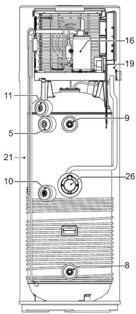
fig. 3

area
| X-Axis | Y-Axis | |---|---| | -1.0 | 65 | | -0.5 | 62 | | 0.0 | 62 | | 0.5 | 62 | | 1.0 | 62 | | 1.5 | 62 | | 2.0 | 62 | | 2.5 | 62 | | 3.0 | 62 | | 3.5 | 62 | | 4.0 | 62 | | 4.5 | 62 | | 5.0 | 62 | | -1.0 | 75 | | -0.5 | 75 | | 0.0 | 75 | | 0.5 | 75 | | 1.0 | 75 | | 1.5 | 75 | | 2.0 | 75 | | 2.5 | 75 | | 3.0 | 75 | | 3.5 | 75 | | 4.0 | 75 | | -1.0 | 38 | | -0.5 | 38 | | 0.0 | 38 | | 0.5 | 38 | | 1.0 | 38 | | 1.5 | 38 | | 2.0 | 38 | | 2.5 | 38 | | 3.0 | 38 | | 3.5 | 38 | | 4.0 | 38 | | -1.0 | 43 | | -0.5 | 43 | | 0.0 | 43 | | 0.5 | 43 | | 1.0 | 43 | | 1.5 | 43 | | 2.0 | 43 | | 2.5 | 43 | | 3.0 | 43 | | 3.5 | 43 | | 4.0 | 43 | | -1.0 | 43 | | -0.5 | 43 | | 0.0 | 43 | | 0.5 | 43 | | 1.0 | 43 | | 1.5 | 43 | | 2.0 | 43 | | 2.5 | 43 | | 3.0 | 43 | | -1.0 | 43 | | -0.5 | 43 | | 0.0 | 43 | | 0.5 | 43 | | 1.0 | 43 | | 1.5 | 43 | | 2.0 | 43 | | -1.0 | 43 | | -0.5 | 43 | | -1.0 | 43 | | -1.5 | 43 | | -2.0 | 43 | | -2.5 | 43 | | -3.0 | 43 | | -3.5 | 43 | | -4.0 | 43 | | -4.5 | 43 | | -5.0 | 43 | | -1.0 | 62 | | -1.5 | 62 | | -2.0 | 62 | | -2.5 | 62 | | -3.0 | 62 | | -3.5 | 62 | | -4.0 | 62 | | -4.5 | 62 | | -5.0 | 62 | | -1.0 | 62 | | -1.5 | 62 | | -2.0 | 62 | | -2.5 | 62 | | -3.0 | 62 | | -3.5 | 62 | | -4.0 | 62 | | -4.5 | 62 | | -5.0 | 62 | | -1.0 | 69 | | -1.5 | 69 | | -2.0 | 69 | | -2.5 | 69 | | -3.0 | 69 | | -3.5 | 69 | | -4.0 | 69 | | -4.5 | 69 | | -5.0 | 69 | | | -1.0 | B: Value (approx.) for the shaded region between C and D (approx.) from C to D (approx.) on the x-axis; B: Value (approx.) for the shaded region between C and D (approx.) on the y-axis; B: Value (approx.) for the shaded region between C and D (approx.) on the x-axis; B: Value (approx.) for the shaded region between C and D (approx.) on the y-axis; B: Value (approx.) for the shaded region between C and D (approx.) on the x-axis; B: Value (approx.) for the shaded region between C and D (approx.) on the y-axis; B: Value (approx.) for the shaded region between C and D (approx.) on the x-axis; B: Values range from approximately 75°C to75°C; B: Values range from approximately 75°C to75°C; B: Values range from approximately 75°C to75°C; B: Values range from approximately 75°C to75°C; B: Values range from approximately 75°C to75°C; B: Values range from approximately 75°C to75°C; B: Values range from approximately 75°C to75°C; B: Value ranges from approximately 75°C to75°C; B: Value ranges from approximately 75°C to75°C; B: Value ranges from approximately 75°C to75°C; B: Value ranges from approximately 75°C to75°C; B: Value ranges from approximately 75°C to75°C; B: Value ranges from approximately 75°C to75°C; B: Value ranges from approximately 81°C to81°C; B: Value ranges from approximately 81°C to81°C; B: Value ranges from approximately 81°C to81°C; B: Value ranges from approximately 81°C to81°C; B: Value ranges from approximately 81°C to81°C; B: Value ranges from approximately 81°C to81°C; B: Value ranges from approximately 81°C to81°C; B : Value ranges from approximately 81°C to81°C; B : Value ranges from approximately 81°C to81°C; B : Value ranges from approximately 81°C to81°C; B : Value ranges from approximately 81°C to81°C; B : Value ranges from approximately 81°C to81°C; B : Value ranges from approximately 81°C to81°C; B : Value ranges from about 81°C to81°C; B : Value ranges from approximately 81°C to81°C; B : Value ranges from approximately 81°C to81°C; B : Value ranges from approximately 81°C to81°C; B : Value ranges from approximately 81°C to81°C; B : Value ranges from approximately 81°C to81°C; B : Value ranges from approximately 81C to81C; B : Value ranges from approximately 81C to81C; B : Value ranges from approximately 81C to81C; B : Value ranges from approximately 81C to81C; B : Value ranges from approximately 81C to81C; B : Value ranges from approximately 81C to81C; B : Value ranges from approximately 81C to81C; B : value ranges from approximately 81C to81C; B : value ranges from approximately 81C to81C; B : value ranges from approximately 81C to81C; B : value ranges from approximately 81C to81C; B : value ranges from approximately 81C to81C; B : value ranges from approximately 81C to81C; B : value ranges from approximately S/A or S/A in the grid; B : value ranges from approximately S/A or S/A in the grid; B : value ranges from approximately S/A or S/A in the grid; B : value ranges from approximately S/A or S/A in the grid; B : value ranges from approximately S/A or S/A in the grid; B : value ranges from approximately S/A or S/A in the grid; B : value ranges from approximately S/A or S/A in the grid; B : value ranges from approximately S/A / S/A in the grid; B : value ranges from approximately S/A / S/A in the grid; B : value ranges from approximately S/A / S/A in the grid; B : value ranges from approximately S/A / S/A in the grid; B : value ranges from approximately S/A / S/A in the grid; B : value ranges from approximately S/A / S/A in the grid; B : value ranges from approximately S/A / S/A in the grid; B : value ranged from approximately S/A / S/A in the grid; B : value ranges from approximately S/A / S/A in the grid; B : value ranges from approximately S/A / S/A in the grid; B : value ranges from approximately S/A / S/A in the grid; B : value ranges from approximately S/A / S/A in the grid; B : value ranges from approximately S/A / S/A in the grid; B : value ranges from approximately S/A / S/A in the matrix of these values, respectively. The chart displays a single shaded region representing a variable's magnitude across the x-axis (labeled 'a' at top) and y-axis (labeled 'b') with a constant vertical line at y=4. The shaded region is filled with varying shades of gray, indicating different intensity levels of the variable's response.fig. 7 - Grafico
natural_image
Technical line drawing of a mechanical assembly with three components and mounting holes (no text or symbols)natural_image
Pure technical line drawing of a curved mechanical component with mounting holes and directional arrows (no text or symbols)natural_image
Simple electrical outlet symbol with two terminals and a circular outline (no text or labels)fig. 18 - Presa Schuko

natural_image
Technical illustration of a mechanical connector or plug (no text or symbols)fig. 19 - Spina apparecchio
5.6.1 Collegamenti remoti
natural_image
Line drawing of a vertical cylindrical device connected to a wall-mounted power outlet (no text or symbols)fig. 24
fig. 25

fig. 26
fig. 27
fig. 28
fig. 29
fig. 33
fig. 35
fig. 36
fig. 37
fig. 38
fig. 39
natural_image
Technical line drawing of a mechanical assembly with an inset showing internal components (no text or symbols)fig. 40
natural_image
Technical line drawing of a cylindrical industrial device with internal components and ventilation grilles (no text or symbols)natural_image
Technical line drawing of a mechanical assembly with internal components and an inset view showing a close-up of a component (no text or symbols present)natural_image
Line drawing of a cylindrical industrial machine with two vented chambers and a handle (no text or symbols)fig. 43
11. FICHA PRODUCTO....65
1. INTRODUCCIÓN
natural_image
Illustration of a worker installing or adjusting a cylindrical device with green checkmarks (no text or symbols present)fig. 1

natural_image
Technical diagram of a cylindrical mechanical component with mounting holes and internal features (no text or symbols)fig. 2
3. CARACTERÍSTICAS CONSTRUCTIVAS


fig. 3

natural_image
Technical line drawing of a mechanical assembly with three components and mounting holes (no text or symbols)natural_image
Pure technical line drawing of a curved mechanical component with mounting holes and directional arrows (no text or symbols)natural_image
Simple electrical outlet symbol with three terminals and mounting holes (no text or labels)
natural_image
Illustration of a mechanical connector or plug with a threaded end and multiple pins (no text or symbols)fig. 18 - Toma Schuko fig. 19 - Clavija aparato
natural_image
Line drawing of a vertical electrical cabinet with connected piping and a pressure gauge (no text or symbols)fig. 23
6.5.8 Modo Off-Peak HP HP HP
fig. 24
fig. 25
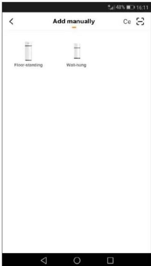
fig. 26
fig. 27
fig. 28
fig. 29
fig. 33
fig. 35
fig. 36
fig. 37
fig. 38
fig. 39
natural_image
Technical line drawing of a mechanical assembly with an inset showing internal components (no text or symbols)fig. 40
natural_image
Technical line drawing of a cylindrical industrial device with two circular vented ports and internal components (no text or symbols)natural_image
Technical line drawing of a mechanical assembly with internal components and an inset view showing a component detail (no text or symbols present)natural_image
Line drawing of a cylindrical industrial machine with two vented chambers and a handle (no text or symbols)fig. 43
1. INTRODUCTION......68
1.1 Products 68
1.2 Disclaimer....68
1.3 Copyright 69
1.4 Available versions and configurations 69
2. HANDLING AND TRANSPORT ......69
2.1 Receipt....69
3. CONSTRUCTION CHARACTERISTICS....71
3.1 Dimensional data....72
3.2 Technical characteristics....73
4. IMPORTANT INFORMATION....74
4.1 Compliance with European regulations 74
4.2 Casing protection rating 74
4.3 Operating limits....74
4.4 Operating limits 74
4.5 Basic safety rules....75
4.6 Information on the refrigerant used 75
5. INSTALLATION AND CONNECTIONS ....75
5.1 Preparation of place of installation 75
5.2 Securing to the floor....76
5.3 Aeraulic connections....76
5.4 Securing and connections of EGEA....78
5.5 Plumbing connections 78
5.6 Electrical connections 79
5.7 Wiring diagram....81
6. DESCRIPTION OF USER INTERFACE AND OPERATION OF EQUIPMENT 82
6.1 Turning the water heater on and off and unlocking the buttons....83
6.2 Setting the clock 83
6.3 Setting time bands....83
6.4 Setting the hot water set-point 83
6.5 Operating mode 83
6.6 Additional functions....84
6.7 Control of equipment via APP 85
6.8 Faults/protection 90
7. COMMISSIONING....91
7.1 Query, editing operating parameters 91
8. TROUBLESHOOTING....94
8.1 Power board fuse replacement....95
8.2 Heating element safety thermostat reset....95
9. MAINTENANCE....96
9.1 Sacrificial anode check/replacement 96
9.2 Boiler emptying 96
10. DISPOSAL....97
11. PRODUCT SHEET ......97
1. INTRODUCTION
This installation and maintenance manual is an integral part of the heat pump (hereinafter equipment).
The manual must be kept for future reference until dismantling. It is intended for the specialist installer (installers - maintenance technicians) and the end user. The manual describes the installation procedures to be observed for correct and safe operation of the equipment, and the methods of use and maintenance.
In case of sale or transfer to another user, the manual must stay with the unit.
Before installing and Vor using the equipment, read this instruction manual carefully and in particular chapter 4 on safety.
The manual must be kept with the unit and always be available to qualified installation and maintenance personnel.
The following symbols are used in the manual for quickly finding the most important information:
| Safety information | |
| Procedures to be followed | |
| Information / Suggestions |
1.1 Products
Dear Customer,
Thank you for purchasing this product.
Our company, always attentive to environmental issues, uses low environmental impact technologies and materials for its products, in compliance with EU WEEE standards (2012/19/EU – RoHS 2011/65/EU).
1.2 Disclaimer
The conformity of these operating instructions with the hardware and the software has been carefully checked. Nevertheless there may be differences; and no responsibility is assumed for total conformity.
In the interest of technical improvement, we reserve the right to make construction or technical data changes at any time. Any claim based on indications, figures, drawings or descriptions is therefore excluded. They are subject to possible errors.
The supplier declines any liability for damage due to command errors, improper or inappropriate use, or due to unauthorized repairs or modifications.

ATTENTION!: The unit can be used by children aged 8 years and over and by persons with reduced physical, sensory or mental capacities, or lacking in experience or the necessary knowledge, provided they are supervised or have received instructions regarding safe use of the unit and understand the related hazards. Children must not play with the unit. Cleaning and maintenance intended to be performed by the user must not be performed by unsupervised children.
1.3 Copyright
These operating instructions contain information protected by copyright. No part of these operating instructions may be photocopied, duplicated, translated or recorded on storage media without prior permission from the supplier. Any violations will be subject to compensation for damage. All rights, including those resulting from the granting of patents or registration of utility models, are reserved.
1.4 Available versions and configurations
This equipment is a 1.6 kW air-water heat pump for domestic hot water heating, available in versions with 200 L tank and 260 L tank.
| Version Configuration description | |
| 200 HT260 HT | Air heat pump for domestic hot water (DHW) production |
2. HANDLING AND TRANSPORT
The equipment comes in a cardboard box(*).
It is secured to a pallet by means of three screws.
For unloading operations use a forklift or pallet truck having a load capacity of at least 250 kg.
The packed equipment can be placed horizontally and back down to facilitate undoing the anchoring screws.
Unpacking must done carefully so as not to damage the equipment casing if using knives or cutters to open the cardboard packaging.
After removing the packaging, check the integrity of the unit. If in doubt, do not use the unit; contact authorized technical personnel.
Before eliminating the packaging, according to the applicable environmental protection regulations, make sure all the accessories supplied have been removed.

ATTENTION!: The packaging materials (clips, cardboard, etc.) must not be left within the reach of children as they are hazardous for them.
(*) Note: The type of packaging may undergo variations at the discretion of the manufacturer.
For the entire period the equipment remains idle, awaiting commissioning, it is advisable to put it in a place protected from atmospheric agents
2.1 Receipt
In addition to the units, the packages contain accessories and technical documentation for use and installation. Check that the following are present:
- user and installation manual
For the entire period the equipment remains idle, awaiting commissioning, it is advisable to put it in a place protected from atmospheric agents.
Positions allowed for transport and handling

natural_image
Illustration of a cylindrical device with green checkmarks indicating inspection or status, alongside a worker inspecting a battery (no text or symbols present)fig. 1

ATTENTION! During the product handling and installation phases the upper part must not be stressed in any way, as it is not structural.

ATTENTION! Horizontal transport is allowed only for the last km according to that indicated (see "Positions NOT permitted and handling"), making sure supports are positioned in such a way at the bottom of the boiler so as not to stress the upper part, as it is not structural. During horizontal transport the display must face upwards.
Position allowed only for the last km

natural_image
Technical diagram of a cylindrical mechanical component with internal features and mounting holes (no text or symbols)Positions not allowed for transport and handling
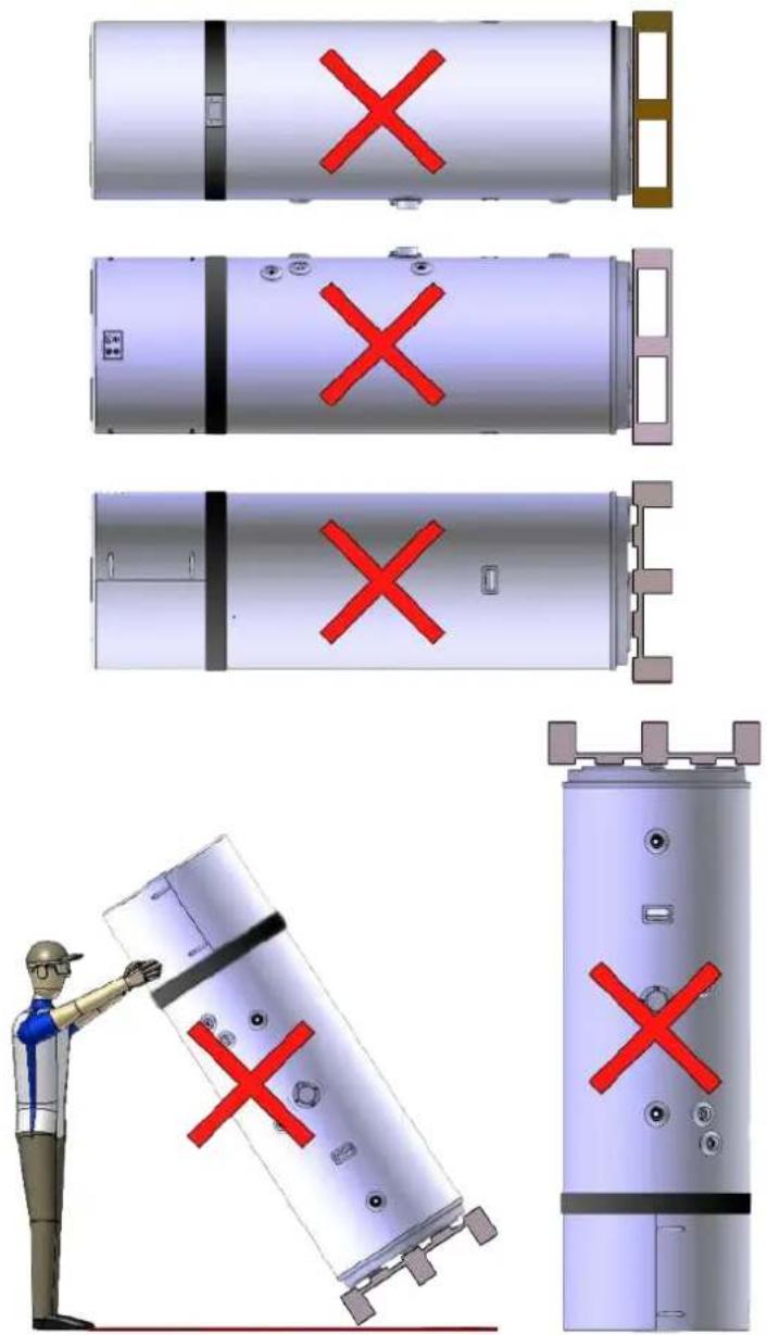
fig. 2
3. CONSTRUCTION CHARACTERISTICS


fig. 3

1 Heat pump
2 User interface
3 Steel casing
4 Heating element
5 Magnesium anode
6 Ventilation air inlet (∅ 160 mm)
7 Ventilation air outlet (∅ 160 mm)
8 Cold water inlet connection
9 Hot water outlet connection
10 Prearrangement for recirculation
11 Condensate drain
14 Steel tank with vitreous enamel coating according to DIN 4753-3
15 Condenser
16 Rotary compressor
17 Finned pack evaporator
18 Asynchronous fan
19 Boiler probes
21 Polyurethane insulation
22 Carrying handles
23 Tube for safety thermostat bulb
24 Power board
25 Wi-Fi card
26 Compartment for accessing heating element and safety thermostat bulb
3.1 Dimensional data

fig. 4

fig. 5
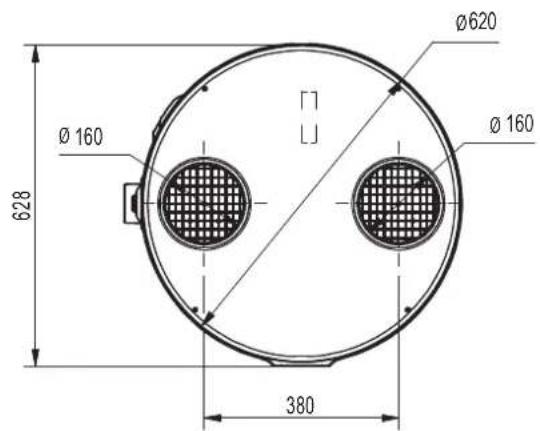
fig. 6
| MODEL | ∅ | 200 HT | 260 HT | UM |
| A | 1"G | 250 | 250 | mm |
| B | - | 490 | 493 | mm |
| D | - | 705 | 785 | mm |
| E | 1"G | 876.5 | 1162 | mm |
| G | - | 1142 | 1427 | mm |
| H | - | 1607 | 1892 | mm |
| M | 3/4"G | 705 | 735 | mm |
| N | 3/4"G | 877 | 1162 | mm |
| O* | 1/2"G | 976 | 1261 | mm |
| P | - | 1073 | 1358 | mm |
*O - Outlet connection in plastic material
3.2 Technical characteristics
| Model 200 HT 260 HT - | ||||
| Heat pump | Power supply 230-1-50 V-f-Hz | |||
| Thermal power (ISO) 1600 1600 W | ||||
| Total absorbed power in heating (ISO) 370 370 W | ||||
| COP (ISO) 4.32 4.32 W/W | ||||
| Rated current in heating (ISO) | 1.70 | 1.70 | A | |
| Max. total absorbed power in heating | 500 500 W | |||
| Max. current in heating | 2.30 | 2.30 | A | |
| Heating time (EN) (1) | 7:16 | 9:44 | h:min | |
| Heating energy (EN) (1) | 2.83 | 3.74 | kWh | |
| Standby consumption (EN) (1) | 27.3 | 31 | W | |
| Class of use (EN) (1) | L | XL Type | ||
| Power consumption during operating cycle WEL-TC (EN) (1) | 4.18 | 6.17 | kWh | |
| COPDHW (EN) (1) | 2.80 | 3.10 | W/W | |
| COPDHW (EN) (4) | 2,50 | 2,60 | W/W | |
| Water reference temperature (EN) (1) | 51.4 | 53.7 | °C | |
| Max. usable amount of water( EN) (2) | 0.260 | 0.358 | m^3 | |
| Heating efficiency ref. standard (EU) | 116 | 127 | % | |
| Efficiency class ref. standard (EU) | A+ | A+ | - | |
| Yearly power consumption (EU) | 883 | 1315 | kWh/year | |
| Electrical heating element | Power | 1500 1500 W | ||
| Current | 6.5 | 6.5 | A | |
| Heat pump + Electrical heating element | Total absorbed power | 1870 1870 W | ||
| Rated current | 8.20 | 8.20 | A | |
| Total max. absorbed power | 2000 2000 W | |||
| Max. current | 8.80 | 8.80 | A | |
| Heating time (1) | 3:48 | 4:57 | h:min | |
| Storage | Storage capacity | 192 250 | L | |
| Max. pressure | 0.7 | 0.7 MPa | ||
| Material | Enameled steel | type | ||
| Cathodic protection | Mg anode | type | ||
| Insulation type\thickness | polyurethane/50 | type/mm | ||
| Air circuit | Fan type | Centrifugal | type | |
| Air flow rate | 350 350 | m^3/h | ||
| Duct diameter | 160 160 | mm | ||
| Max. available head | 100 100 | Pa | ||
| Refrigeration circuit | Compressor | Rotary | type | |
| Refrigerant | R134a | type | ||
| Evaporator | Aluminum - Aluminum Finned coil | type | ||
| Condenser | Aluminum tube wound outside tank | type | ||
| Internal sound power levels (3) | 52 | 52 | dB(A) | |
| External sound power levels (3) | 50 | 50 | dB(A) | |
| Empty weight | Net | 80 | 95 | kg |
NOTES
• (ISO): data according to standard ISO 255-3
• (EN): data according to standard EN 16147:2017
• (EU): data according to regulation 2017/1369/EU
• (1): Heating cycle Air inlet temp = 20°C BS/15°C BU Initial water temperature 10°C
• (2): Operating temperature limit 40°C - Water inlet temperature 10°C
• (3): data according to standard EN 12102-1:2018
• (4): Heating cycle Air inlet temp = 14°C BS/13°C BU Initial water temperature 10°C
4. IMPORTANT INFORMATION
4.1 Compliance with European regulations
This heat pump is a product intended for domestic use in compliance with the following European directives:
• Directive 2012/19/EU general product safety
- Directive 2011/65/RoHS on the restriction of the use of certain hazardous substances in electrical and electronic equipment (RoHS)
- Directive 2003/108/EC hazardous substances in electrical and electronic equipment (WEEE)
• Directive 2014/30/EU electromagnetic compatibility (EMC)
• Directive 2014/35/EU low voltage (LVD)
• Directive 2009/125/EC eco-friendly design
• Directive 2014/53/EU radio equipment (RED)
• Regulation 2017/1369/EU energy labeling
4.2 Casing protection rating
The equipment protection rating is: IP24.
4.3 Operating limits

PROHIBITION! This product is not designed or intended for use in hazardous environments (due to the presence of potentially explosive atmospheres - ATEX or with required IP level higher than that of the unit) or in applications requiring safety features (fault-tolerant, fail-safe) which may be systems and/or technologies to support life or any other context in which the malfunction of an application can lead to death or injury to people or animals, or serious damage to property or the environment.

NBI: If the possibility of a product fault or failure can cause damage (to people, animals and property) it is necessary to provide for a separate functional surveillance system equipped with alarm functions in order to exclude such damage. It is also necessary to arrange the replacement operation!

EGEA is not designed for installation outdoors but in a "closed" place not exposed to the elements.
4.4 Operating limits
The product in question is designed exclusively for heating hot water for sanitary uses within the limits described below. For this purpose, it must be connected to the domestic water supply and the power supply (see chapter "5. INSTALLATION AND CONNECTIONS").
4.4.1 Temperature range
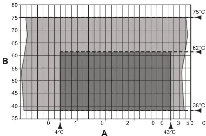
area
| X-Axis | Y-Axis (°C) | |---|---| | -1.0 | 38 | | -0.5 | 40 | | 0.0 | 40 | | 0.5 | 62 | | 1.0 | 62 | | 1.5 | 62 | | 2.0 | 62 | | 2.5 | 62 | | 3.0 | 62 | | 3.5 | 75 | | 4.0 | 75 | | 4.5 | 75 | | 5.0 | 75 |fig. 7 - Chart
A = Inlet air temperature (°C)
B = Hot water temperature (°C)
■ = Operating range for heat pump (HP)
= Integration with heating element only
4.4.2 Water hardness
The unit must not operate with water of hardness under 12^ F; however, with particularly hard water (above 25^ F), it is advisable to use a properly calibrated and monitored water softener, in this case the residual hardness must not fall below 15^ F.

NB! The manufacturer declines any liability for uses different from those for which the equipment is designed, and for any installation errors or improper use of the unit.

PROHIBITION! Using the product for purposes other than that specified is prohibited. Any other use is deemed improper and not permitted.

NB!: In the design and construction phase of the plants, the applicable local regulations and provisions must be respected.
4.5 Basic safety rules
• The product must be used by adults;
- Do not open or disassemble the product when it is electrically powered;
- Do not touch the product if barefoot or with wet or damp parts of the body;
- Do not pour or spray water on the product;
- Do not climb, sit and/or place any type of object on the product.
4.6 Information on the refrigerant used
This product contains fluorinated greenhouse gases included in the Kyoto protocol. Do not release these gases into the atmosphere.
Type of refrigerant: HFC-R134a.

NB!: Maintenance and disposal operations must only be carried out by qualified personnel.
5. INSTALLATION AND CONNECTIONS

ATTENTION! Product installation, commissioning and maintenance must be carried out by qualified and authorized personnel. Do not try to install the product yourself.
5.1 Preparation of place of installation
The product must be installed in a suitable place, i.e. to allow normal use and adjustment operations as well as routine and extraordinary maintenance.
The necessary operating space must therefore be prepared by referring to the dimensions given in fig. 9.

fig. 8 - Minimum spaces

fig. 9 - Minimum spaces
The room must also be:
• Equipped with adequate water and electricity supply lines;
- Prearranged for the condensation water discharge connection;
- Prearranged with adequate water drains in case of boiler damage or safety valve intervention or the breakage of pipes/connections;
- Equipped with possible containment systems in case of serious water leakage;
- Sufficiently illuminated (where required);
• Not less than 20 m3 in volume;
- Protected against frost and be dry.

ATTENTION! To avoid the propagation of mechanical vibrations, do not install the equipment on floors with wooden beams (e.g. in the attic).
5.2 Securing to the floor
To secure the product to the floor, fasten the supplied brackets as shown in fig. 10.

natural_image
Pure mechanical diagram showing three connected components with no text, numbers, or symbolsfig. 10 - Fastening brackets
Then secure the unit to the floor with the aid of suitable plugs, not supplied, as shown in fig. 11.

natural_image
Pure diagram of a curved pipe or channel with directional arrows indicating flow or movement (no text or symbols)fig. 11 - Securing to the floor
5.3 Aeraulic connections
In addition to the spaces indicated in 5.1, the heat pump requires adequate air ventilation.
Create a dedicated air channel as indicated in fig. 12.
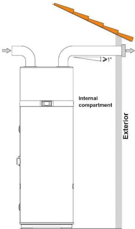
fig. 12 - Example of air outlet connection
Install each air channel, making sure:
- It does not weigh down on the equipment.
- It allows maintenance operations.
- It is adequately protected to prevent the accidental intrusion of materials inside the equipment.
- The connection to the outside must be done with suitable, non-flammable piping.
- The total equivalent length of the extraction pipes plus the delivery, including grilles, must not exceed 12 m.
The table gives the characteristic data of commercial ducting components with reference to nominal air flows and diameters 160 mm.
| Data | Smooth straight pipe | Smooth 90° curve | Grille UM | |
| Type |  | 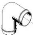 |  | |
| Effective length | 1 \ m | |||
| Equivalent length | 122m |

During operation, the heat pump tends to lower the room temperature if the air ducting is not to the outside.

A suitable protection grille must be installed at the air extraction pipe to the outside to prevent any foreign bodies from entering inside the equipment. To ensure maximum product performance, the grille must be selected from those with low pressure loss.

To avoid the formation of condensation water: insulate the air extraction pipes and the ducted air cover connections with a steam-tight thermal covering of adequate thickness.

Install silencers if deemed necessary to prevent noise due to the flow. Equip the pipes, wall outlets and connections to the heat pump with vibration-damping systems.

ATTENTION!: The simultaneous operation of an open-chamber hearth (e.g. open fireplace) and the heat pump causes a dangerous negative pressure in the room. The negative pressure can cause the return of exhaust gases into the room.
Do not operate the heat pump together with an open-chamber hearth.
Only use sealed-chamber hearths (approved) with separate combustion air supply.
Keep tight and sealed the doors of boiler rooms that do not have the inflow of combustion air in common with living areas.
5.3.1 Special installation
One of the peculiarities of the heat pump heating systems is that these units considerably lower the air temperature, generally expelled to the outside of the house. As well as being colder than the ambient air, the expelled air is also completely dehumidified, therefore the air flow can be returned inside for the summer cooling of specific rooms or areas.
Installation provides for splitting of the extraction pipe, which is fitted with two dampers ("A" and "B") for directing the air flow to the outside (fig. 14) or the inside of the house (fig. 13).

fig. 13 - Example of installation in the summer period

fig. 14 - Example of installation in the winter period
5.4 Securing and connections of EGEA
The product must be installed on a stable, flat floor that is not subject to vibrations.
5.5 Plumbing connections
Connect the cold water supply line and the outlet line to the appropriate connection points (fig. 15).
The table below gives the characteristics of the connection points.
| Ref. Model 200 / 260 UM | ||
| 1 Cold water inlet 1"G " | ||
| 4 Recirculation 3/4"G " | ||
| 5 Hot water outlet 1"G " | ||
| 6 Condensate drain 1/2"G " |
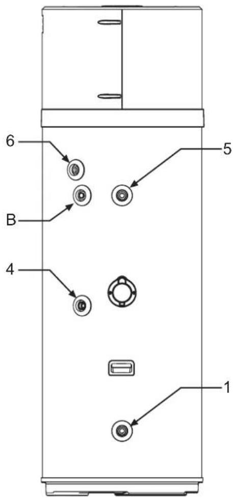
fig. 15
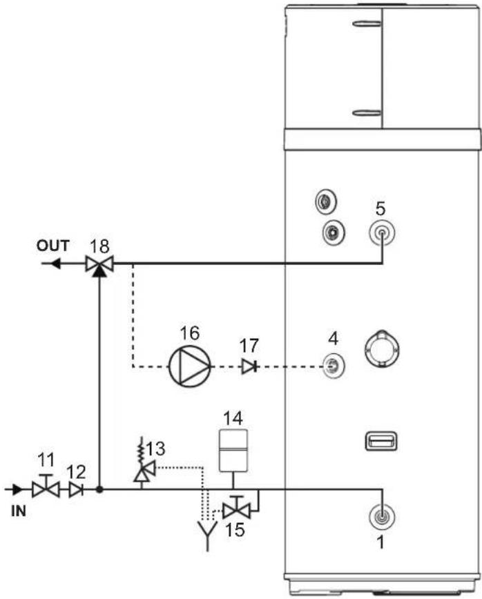
The following figure (fig. 16) illustrates an example of plumbing connection.
flowchart
graph TD
    IN["IN"] --> 11["11"]
    IN --> 12["12"]
    18["18"] --> OUT["OUT"]
    16["16"] --> 17["17"]
    13["13"] --> 15["15"]
    14["14"] --> 15["15"]
    5["5"] --> 4["4"]
    1["1"] --> 15["15"]
fig. 16 - Example of water system
Legend (fig. 16)
1 Cold water inlet
4 Recirculation
5 Hot water outlet
11 Shut-off valve
12 One-way valve
13 Safety valve
14 Expansion vessel
15 Drain cock
16 Recirculating pump
17 Check valve
18 Automatic thermostatic mixing device

MANDATORY!: The system installer is required install a 7 bar safety valve on the cold water inlet.

NB!: The overpressure device must be operated regularly to remove scale deposits and to check that it is not blocked.

NB!: For correct installation of the unit, a hydraulic safety unit in conformity with UNI EN 1487: 2002 must be provided at the feed inlet and include at least: a shut-off valve; a check valve; a check valve control device; a safety valve; a hydraulic load cut-off device.

NB!: The discharge pipe connected to the overpressure device must be installed in a continuous downward slope and in a place protected against the formation of ice.

Water may drip from the discharge pipe of the overpressure device and this pipe must be left open to the atmosphere.

ATTENTION!: The heat pump for DHW production can heat the water to over 60°C. Therefore, to protect from burns, an automatic thermostatic mixing device must be installed on the hot water piping (fig. 16).
5.5.1 Condensate drain connection
The condensate forming during heat pump operation flows through a special drain pipe (1/2"G) that passes inside the insulating casing and comes out the side of the equipment. It must be connected, via a trap, to a duct so that the condensate can flow regularly (fig. 17).

fig. 17 - Examples of condensate drain connection via a trap
5.6 Electrical connections
The product comes already wired for the mains supply. It is powered via a flexible cable and a combination plug/socket (fig. 18 and fig. 19). For connection to the mains, a Schuko socket with ground and separate protection is required.

ATTENTION!: The power supply line to which the equipment will be connected must be protected by a suitable differential switch.
The type of differential must be chosen according to the type of electrical devices used by the overall plant.
For the mains connection and the safety devices (e.g. differential switch), comply with IEC standard 60364-4-41.

natural_image
Simple electrical outlet symbol with two dots and circuit lines, enclosed in a square frame (no text or labels)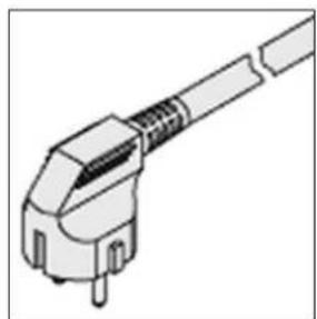
natural_image
Illustration of a mechanical connector or plug assembly (no text or symbols)fig. 18 - Schuko socket fig. 19 - Unit plug
5.6.1 Remote connections
The equipment is prearranged to be connected to other remote energy systems or energy meters (solar thermal, photovoltaic, Off-Peak)
INPUTS
• Digital 1 (DIG1). NOT USABLE
(THE TWO WIRES, WHITE AND BROWN, OF THE 6-CORE CABLE ARE NOT TO BE USED)
- Digital 2 (DIG2). Digital input for photovoltaic. In case of a photovoltaic system connected to the plant, it can be used to subtract energy in the form of hot water in times of overproduction. If there is a voltage-free contact, e.g. from the inverter, which closes when there is overproduction of energy, it can be connected to the two green and yellow wires of the 6-core cable supplied with the equipment.
Set the parameter P23 = 1 to activate the supplement with photovoltaic.
- Digital 3 (DIG3). Input for Off-Peak. This function, available only in some countries, allows the equipment to be activated only when there is a signal coming from outside with prefer-
ential tariff. If the electric contactor has a voltage-free contact which closes when the preferential tariff is available, it can be connected to the two gray and pink wires of the 6-core cable supplied with the equipment.
Set the parameter P24 = 1 to activate Off-peak in ECO mode or P24 = 2 for Off-peak in AUTO mode.
5.6.1.1 Remote connection
For the connection to the digital inputs the equipment is supplied with an additional 6-core cable already connected to the PCB of the user interface (located inside the device). The remote connections to possible energy systems are the responsibility of the qualified installer (connection boxes, terminals and connection cables).
The following figures give an example of remote connection (fig. 20 and fig. 21) which must not be longer than 3 m.

natural_image
Line drawing of a vertical electrical cabinet with connected piping and a sensor (no text or symbols)fig. 20 - Example of remote connection
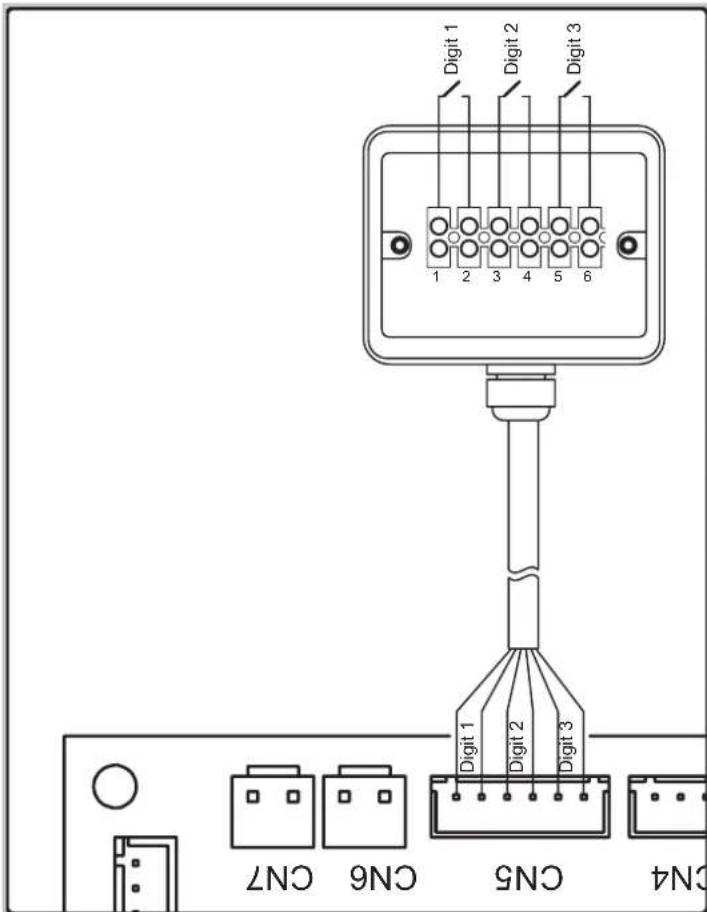
fig. 21
To access the 6-core cable for remote connection, remove the upper cover of the boiler and run to the outside the cable, already present inside the unit, through the special cable gland installed in the back cover.
5.7 Wiring diagram
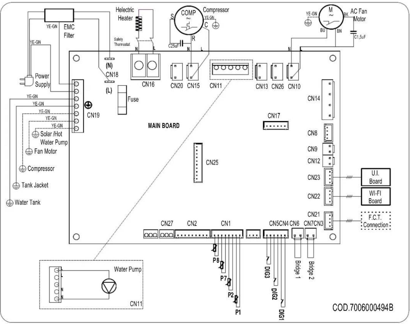
fig. 22 - Equipment wiring diagram
Description of connections available on the power board
| CN1 Air, defrost and water NTC probes |
| CN2 Not usable |
| CN3 Not usable |
| CN4 Not usable |
| CN5 Solar digital inputs (Not usable), PV, Off-peak |
| CN6 Not usable |
| CN7 Flow switch for DHW circulating pump |
| CN8 Not usable |
| CN9+CN12 Not usable |
| CN10 Fan power supply EC, AC |
| CN11 DHW circulating pump |
| CN13 Not usable |
| CN14 Not usable |
| CN15 Compressor power supply |
| CN16 Heating element power supply | |
| CN17 Not usable | |
| CN18 Main power supply | |
| CN19 Ground connections | |
| CN20 | 230 Vac power supply for impressed current anode converter |
| CN21 Connection with end of line inspection/test | |
| CN22 WI-FI card connection | |
| CN23 User interface connection | |
| CN25 Not usable | |
To connect a safety flow switch for the DHW recirculation circuit to the equipment, proceed as follows (reserved only for qualified technical personnel):
- Disconnect the power to the equipment.
- Remove the top cover of the equipment and then the power board cover.
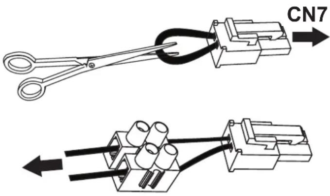
- Disconnect the "jumper" (bridge 2) from connector CN7 of the power board, then cut the conductor forming the bridge in the middle and connect a suitable terminal.
- Then connect a normally-closed (N.C.) type flow switch and connect everything to CN7.
- Reassemble all the plastics and make sure the equipment is correctly installed before powering it.
If, instead, a normally-open (N.O.) type flow switch is used, it is necessary to set the parameter P15 = 1 (see par. 7.1).
6. DESCRIPTION OF USER INTERFACE AND OPERATION OF EQUIPMENT

fig. 23
| Description Symbol | |
| "On/Off" button for switching on, putting the product in standby mode, unlocking buttons, saving changes |  |
| "Set" button to edit the parameter value, confirm; |  |
| "Increase" button to increase the set-point value, parameter or password |  |
| "Decrease" button to decrease the set-point value, parameter or password |  |
| Heat pump operation (ECO mode) |  |
| Heating element operation (electric mode) |  |
| Automatic mode |  |
| Boost mode (symbols flash) |  |
| Button lock active |  |
| Defrost |  |
| Frost protection |  |
| Anti-legionella cycle |  |
| Holiday mode; | [KTTH] |
| Operation with time bands |  |
| Clock setting (symbol flashes) |  |
| Connected with WI-FI(the symbol flashes when there is no connection) | [OK44] |
| Photovoltaic mode(with symbol flashing the supplement is not active) |  |
| NOT USABLE |  |
| Fault or protection active |  |
| Off-Peak mode (with symbol flashing the equipment remains on standby) | [A530] |
The user interface of this water heater model consists of four capacitive buttons, and a LED display.
As soon as the water heater is powered the four buttons are
backlit and all the icons and display segments light up simultaneously for 3 s.
During normal operation of the product the three digits on the display show the water temperature in ^ C, measured with the upper water probe if parameter P11 is set to 1 or with the lower water probe if P11 = 0.
During modification of the selected operating mode set-point, the set-point temperature is shown on the display.
The icons indicate the selected operating mode, the presence or not of alarms, WI-Fi connection status, and other information on product status.
6.1 Turning the water heater on and off and unlocking the buttons
When the water heater is correctly powered it can be "ON" and, therefore, in one of the available operating modes (ECO, Automatic, etc.) or in standby mode.
During standby mode the four capacitive buttons are backlit for easy visibility, the Wi-Fi icon is lit up according to the connection status with an external Wi-Fi router (not supplied) and, in the absence of alarms or frost protection active, all other icons as well as the segments of the three digits are off.
Turning on
With the water heater in standby mode and "button lock" function active (padlock icon at the bottom left lit up), it is necessary to first "unlock" the buttons by pressing the ON/OFF button for at least 3 seconds (the padlock icon goes off), then press the ON/OFF button again for 3 seconds to turn on the water heater.
Turning off
With the water heater on and "button lock" function active, it is necessary to first "unlock" the buttons by pressing the ON/OFF button for at least 3 seconds, then press the ON/OFF button again for 3 seconds to turn off the water heater (putting in standby mode).
In any status, 60 seconds after the last press of any of the four user interface buttons, the button lock function is automatically activated to prevent possible interactions with the water heater, e.g. by children, etc. At the same time the backlighting level of the buttons and display decreases to reduce the unit's energy consumption.
By pressing any of the four buttons, the backlighting of the buttons and display will immediately return to its normal level for better visibility.
6.2 Setting the clock
With the buttons unlocked, press the button SET for 3 seconds to access the clock settings (the symbol 📊 flashes).
Set the time with the "+" and "-" buttons, press "SET" to confirm and then set the minutes.
Press the button SET to confirm and exit.
6.3 Setting time bands
The equipment clock must be set before activating the time bands.
Select the desired operating mode then set the time bands.
The time bands can be activated only in the ECO - AUTOMATIC - BOOST - ELECTRIC and VENTILATION modes.
With the buttons released, press th button SET and "-" button together for 3 seconds to set the time bands (the symbol 🔒 is displayed).
Set the switch-on time using the "+" and "-" buttons, press "SET" to confirm and then set the On minutes.
Press SET to confirm and go to switch-off time setting.
Press SET to confirm, then, using the "+" and "-" buttons, select the desired operating mode for the time band (ECO, AUTOMATIC, BOOST, ELECTRIC, VENTILATION).
Press SET to confirm and exit.
Note: At the end of the time band the equipment goes to standby mode and remains there until repetition of the time band the next day
To deactivate the time bands, set the on and off times to midnight (the symbol 📋 goes off).
6.4 Setting the hot water set-point
It is possible to adjust the hot water set-point in the ECO, AUTOMATIC, BOOST and ELECTRIC modes
Select the desired mode with the button SET, then adjust the set-point with the "+" and "-" buttons.
Press the button to confirm and to exit
| Mode | Hot water set-point | |
| Range Default | ||
| ECO 38÷62°C 55°C | ||
| AUTOMATIC 38÷62°C 55°C | ||
| BOOST 38÷75°C* 55°C | ||
| ELECTRIC 38÷75°C 55°C | ||
* In BOOST mode the maximum set-point value for the heat pump is 62°C. Therefore, by setting a higher value this is to be considered only for the heating element.
6.5 Operating mode
The following modes are available for this water heater
6.5.1 ECO
The display shows the symbol HP
With this mode only the heat pump is used within the product operating limits to ensure maximum possible energy saving.
The heat pump is switched on 5 minutes after selecting this mode or from the last switch-off.
In case of switching off, within the first 5 minutes, the heat pump will remain on anyway to ensure at least 5 minutes of continuous operation.
6.5.2 AUTOMATIC
The display shows the symbol HP.
With this mode the heat pump is used and, if necessary, also the heating element, within the product operating limits, to ensure best possible comfort.
The heat pump is switched on 5 minutes after selecting this mode or from the last switch-off.
In case of switching off, within the first 5 minutes, the heat pump will remain on anyway to ensure at least 5 minutes of continuous operation.
6.5.3 BOOST
The display shows the symbols HP flashing.
This mode uses the heat pump and the heating element, within the product operating limits, to ensure faster heating.
The heat pump is switched on 5 minutes after selecting this mode or from the last switch-off.
In case of switching off, within the first 5 minutes, the heat pump will remain on anyway to ensure at least 5 minutes of continuous operation.
The heating element is switched on immediately.
6.5.4 ELECTRIC
The display shows the symbol 🐎
With this mode only the heating element is used within the product operating limits and is useful in situations of low inlet air temperatures.
6.5.5 VENTILATION
The display shows the message FRn
With this mode only the electronic fan inside the equipment is used and is useful for recirculating the air in the installation room if desired.
In automatic mode the fan will be adjusted to the minimum speed.
6.5.6 HOLIDAY
The display shows the symbol ✗
This mode is useful when away for a limited time and then automatically finding the equipment working in automatic mode.
Using the + and - buttons it is possible set the days of absence during which the equipment is to remain in standby mode.
Press SET and then on off to confirm.

6.5.7 Photovoltaic Mode HP for + oHP 🎨 ✿
When the photovoltaic mode is activated from the installer menu, only ECO - AUTOMATIC - HOLIDAY will be available.
When the symbol ⚙ on the display flashes, the photovoltaic mode is not operating and the unit works in the set mode: ECO, AUTOMATIC or HOLIDAY.
When the symbol 📂 on the display is lit up, the energy produced by the photovoltaic system is used to heat the water inside the tank.
With ECO mode selected, the heat pump will operate until the set-point is reached and the heating element is switched on until the photovoltaic set-point set from the installer menu is reached. Otherwise, with AUTOMATIC mode selected, the heating element can also be switched on before reaching the set-point of this mode if the conditions require it.
6.5.8 Off-Peak Mode HP or + HP 🎨
When the photovoltaic mode is activated from the installer menu, only ECO - AUTOMATIC will be available.
When the symbol 📊 on the display flashes, the Off-Peak mode is not operating and the unit remains on standby and the heat pump and heating element are off.
Otherwise, when the symbol on the display is lit up, the unit works in the ECO or AUTOMATIC mode.
6.6 Additional functions
6.6.1 Anti-Legionella
The display shows the symbol
Every two weeks, at the set time, a water heating cycle is carried out by means of the heating element inside the tank, up to the anti-legionella temperature, maintaining it for the set time.
If, on reaching the anti-legionella temperature, the cycle is not performed correctly within 10 hours, it is stopped and will be run again after 2 weeks.
If the request for the anti-legionella function occurs with HOLIDAY mode selected, the anti-legionella cycle will be carried out immediately when the unit is reactivated after the set days of absence.
| Anti-legionella parameters Range Default | ||
| Anti-legionella temperature set-point (P3) 50÷75°C 75°C | ||
| Anti-legionella cycle duration (P4) 0÷90 min | 30 min | |
| Anti-legionella cycle activation time (P29) 0÷23 h 23 h |
6.6.2 Defrost function
The display shows the symbol
This equipment has an automatic evaporator defrost function which is activated, when the operating conditions require it, during heat pump operation.
Defrosting occurs through the injection of hot gas into the evaporator, allowing it to be rapidly defrosted.
During defrosting, the heating element, which the equipment is provided with, is switched off unless otherwise set via the installer menu (parameter P6).
The max. duration of defrosting is 8 minutes.
6.6.2.1 Frost protection
The display shows the symbol ♂.
This protection prevents the water temperature inside the tank from reaching values close to zero.
With the equipment in standby mode, when the water temperature inside the tank is below or equal to 5^ C (parameter configurable via installer menu), the frost protection function activates, which switches on the heating element until 12^ C is reached (parameter configurable via installer menu).
6.7 Control of equipment via APP
This water heater has a Wi-Fi module integrated in the product, enabling connection to an external Wi-Fi router (not supplied) and therefore being controlled via smartphone APP.
Depending on the availability of a smartphone with Android ^® or iOS ^® operating system, via the dedicated app.


Download and install the "EGEA Smart" app

Start the "EGEA Smart" app from your smartphone by pressing the icon as indicated above.
User registration
To use the "EGEA Smart" application for the first time, user registration is required: create a new account → enter the mobile number/email address → enter the verification code and set the password → confirm.

fig. 24
Press the register button to register, then enter your mobile number or email address to obtain the verification code needed for registration.
Press the "+" button at the top right to select your water heater model: wall-mounted or pedestal version.

fig. 25

fig. 26
Make sure the equipment is powered.
With the buttons released, press the button SET + together for 5 seconds. When the Wi-Fi symbol on the display flashes fast, press the confirm button on the app.

fig. 27
Select the Wi-Fi network and enter the password of the network for connecting the equipment, then press confirm on the app.

fig. 28
Wait for the equipment to be connected to the router.

fig. 29
If the procedure for connection with the Wi-Fi router was successful, you will see your device added as shown below.
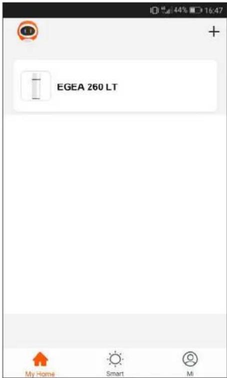
fig. 30
Press on the icon of the equipment to access the control panel

fig. 31
Press on the symbol to select, for example, the automatic operating mode.

fig. 32
The time bands can be activated, in any operating mode except HOLIDAY, by pressing the symbol
Then press on the symbol of the following image.

fig. 33
Set the operating mode desired during time band operation, the equipment switch-on and switch-off time and press the confirm button.
Now, press the back button at the top left.

fig. 34
equipment is in standby mode and this is the screen displayed.

fig. 35
Holiday mode can be activated in any operating mode by pressing on the symbol ✗. Then press on the symbol of the following image.

fig. 36
When time band operation is activated, outside the time band the
Set the number of days of absence and press confirm
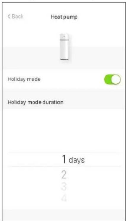
fig. 37
To disable the holiday mode before its end, press the holiday mode "disable" button.

fig. 38
Then press confirm on the next screen.

fig. 39
From the App it is possible to turn off the equipment by pressing on the on/off symbol ⏻ (the symbol is orange when the equipment is on)
6.8 Faults/protection
This equipment has a self-diagnosis system that covers some possible faults or protections from anomalous operating conditions through: detection, signaling and adoption of an emergency procedure until resolution of the fault.
| Fault/Protection Error code Display indication | ||
| Tank lower probe fault P01 | i + P01 | |
| Tank upper probe fault P02 | i + P02 | |
| Defrost probe fault P03 | i + P03 | |
| Inlet air probe fault P04 | i + P04 | |
| Evaporator inlet probe fault P05 | i + P05 | |
| Evaporator outlet probe fault P06 | i + P06 | |
| Compressor flow probe fault P07 | i + P07 | |
| Solar collector probe fault (Not used) P08 | i + P08 | |
| High pressure protection E01 | i + E01 | |
| Recirculation circuit alarm E02 | i + E02 | |
| Temperature not suitable for heat pump operation alarm(With alarm active the water is heated only with heating element) | PA | i + PA |
| No communication (with alarm active the equipment does not work) | E08 | i + E08 |
| Electronic fan fault E03 | i + E03 |
In case of any of the above faults, it is necessary to contact the manufacturer's technical assistance service, indicating the error code shown on the display or on the APP for smartphone.
7. COMMISSIONING

ATTENTION!: Check that the equipment has been connected to the ground wire.

ATTENTION!: Check that the line voltage is that indicated on the equipment rating plate.
Proceed with the following operations for commissioning:
- Fill the tank completely via the inlet faucet and check that there are no water leaks from gaskets and connections.
- Do not exceed the max. permissible pressure indicated in the "general technical data" section.
- Check the water circuit safety devices.
- Plug the unit into the power outlet.
- When the plug is inserted, the boiler is in standby mode, the display remains off, the power button lights up.
- Press the On button, the unit is activated in "ECO" mode (factory setting).
In case of a sudden power outage, when restored the equipment will restart from the operating mode prior to the interruption.
7.1 Query, editing operating parameters
This equipment has two distinct menus, respectively, for consulting and editing the operating parameters (see "7.1.1 List of equipment parameters").
With the equipment operating, the parameters can be freely consulted at any time by unlocking the buttons (see "6.1 Turning the water heater on and off and unlocking the buttons") and pressing the "SET" and "+" buttons together for 3 seconds. The label of the first parameter is shown on the display with the letter "A". Pressing the "+" button displays its value and, pressing this button again, the label of the second parameter "B" is displayed, and so on.
The entire parameter list can then be scrolled forward/back with the "+" and "-" buttons.
Press the "ON/OFF" button to exit.
Editing one or more operating parameters can only be done with the equipment in standby mode and requires the password to be entered.

NB!: "Use of the password is reserved for qualified personnel; any consequences due to incorrect parameter settings will be the sole responsibility of the customer. Therefore, any interventions requested by the customer from an authorized technical assistance center FERROLI during the standard warranty period, for product problems due to incorrect settings of password-protected parameters, will not be covered by the standard warranty."
With buttons unlocked, only in standby mode, press the "SET" and "+" buttons together for 3 seconds to access the equipment parameter editing menu (password protected: 35). The display shows the two digits "00". Press the "SET" button. The digit "0" on the left flashes and with "+" and "-" select the first number to enter (3) and press "SET" to confirm. Proceed in the same way for the second digit (5).
If the password is correct, the parameter P1 is displayed. Pressing the "+" button displays the default value of this parameter which can be modified by pressing SET, and using the "+" and "-" buttons it is possible to change the value within the permissible range for this parameter. Then press SET to confirm and the "+" button to continue with the other parameters.
After editing the desired parameters, press the on/off button to save and exit.
The equipment now returns to standby mode.
7.1.1 List of equipment parameters
| Parameter | Description Range Default Notes | |||
| A Tank lower probe temperature -30÷99°C Measured value Not modifiable | ||||
| B Tank upper probe temperature -30÷99°C Measured value Not modifiable | ||||
| C Defrost probe temperature -30÷99°C Measured value Not modifiable | ||||
| D Inlet air probe temperature -30÷99°C Measured value Not modifiable | ||||
| E | Evaporator input probe temperature | -30÷99°C | Measured value / "0°C" if P33 = 0 | Not modifiable (1) |
| F | Evaporator outlet probe temperature | -30÷99°C | Measured value / "0°C" if P33 = 0 | Not modifiable (1) |
| G | Compressor delivery temperature | 0÷125°C | Measured value / "0°C" if P33 = 0 | Not modifiable (1) |
| H | Solar collector probe temperature (PT1000) | 0÷150°C | Measured value / "0°C" if P16 = 2 | Not modifiable (1) |
| I | EEV opening steps | 30÷500 | Measured value or value of P40 if P39 = 1 | Not modifiable (1) |
| J | Power board firmware version | 0÷99 | Current value | Not modifiable |
| L | User interface firmware version | 0÷99 | Current value | Not modifiable |
| P1 | Hysteresis on lower tank probe for heat pump operation | 2÷15°C | 7°C | Modifiable |
| P2 | Heating element switch-on delay | 0÷90 min | 6 min | Function excluded |
| P3 | Anti-legionella temperature set-point | 50°C÷75°C | 75°C | Modifiable |
| P4 | Anti-legionella duration | 0÷90 min | 30 min | Modifiable |
| P5 | Defrost mode | 0 = compressor stop1 = hot-gas | 0 | Modifiable |
| P6 | Heating element use during defrosting | 0 = off1 = on | 0 | Modifiable |
| P7 | Interval between defrost cycles | 30÷90 min | 45 min | Modifiable |
| P8 | Temperature for defrost start | -30÷0°C | -2°C | Modifiable |
| P9 | Temperature for defrost end | 2÷30°C | 3°C | Modifiable |
| P10 | Defrost cycle max. duration | 3min÷12min | 8 min | Modifiable |
| P11 | Tank probe temperature shown on display | 0 = lower1 = upper | 1 | Modifiable |
| P12 | Type of external pump operation | 0 = function excluded1 = recirculation function2 = solar function | 1 | Modifiable |
| P13 | Type of hot water recirculating pump operation | 0 = operation with HP1 = continuous operation | 0 | Modifiable |
| P14 | Type of evaporator fan (EC; AC; AC two-speed) | 0 = EC1 = AC2 = AC two-speed | 1 | Modifiable |
| P15 | Type of safety flow switch for solar / hot water recirculation circuit | 0 = NC1 = NO | 0 | Modifiable |
| P16 | Solar thermal supplement | 0 = function excluded1 = operation with DIG12 = thermal solar system control | 0 | Modifiable (1) |
| P17 | Heat pump start delay after release DIG.1 in solar mode = 1 (with DIG1) | 10÷60min | 20 min | Modifiable (1) |
| P18 | Tank lower probe temperature for heat pump stop in solar mode = 1 (with DIG.1) | 20÷60°C | 40°C | Modifiable (1) |
| P19 | Hysteresis for pump switch-on in solar mode = 2 (solar thermal system control) | 5÷20°C | 10°C | Modifiable (1) |
| P20 | Solar shutter / discharge valve intervention temperature in solar mode = 2 (solar thermal system control) | 100÷150°C | 140°C | Modifiable (1) |
| P21 | Tank lower probe temperature for heat pump stop in photovoltaic mode | 30÷70°C | 62°C | Modifiable |
| P22 | Tank upper probe temperature for heating element stop in photovoltaic mode | 30÷80°C | 75°C | Modifiable |
| Parameter Description Range Default Notes | ||||
| P23 Photovoltaic supplement | 0 = function excluded1 = enabled | 0 Modifiable | ||
| P24 Operating mode during Off-peak | 0 = function excluded1 = ECO 2 = Automatic | 0 Modifiable | ||
| P25 Offset for tank upper probe -25÷25°C 0°C Modifiable | ||||
| P26 Offset for tank lower probe -25÷25°C 0°C Modifiable | ||||
| P27 Inlet air probe offset -25÷25°C 0°C Modifiable | ||||
| P28 Offset for defrost probe -25÷25°C 0°C Modifiable | ||||
| P29 Anti-legionella cycle activation time 0÷23 hours 23 hours Modifiable | ||||
| P30 | Hysteresis on upper tank probe for heating element operation | 2÷20°C | 7°C Modifiable | |
| P31 | Working time of heat pump in Automatic mode for calculating heating speed | 10÷80 min | 30 min | Modifiable |
| P32 | Threshold on tank lower probe for heating element switch-on in Automatic mode | 0÷20°C | 4°C Modifiable | |
| P33 EEV use | 0 = not used1 = used | 0 Modifiable (1) | ||
| P34 | Overheating calculation interval for EEV with automatic control | 20÷90s | 30 s | Modifiable (1) |
| P35 | Overheating set-point for EEV with automatic control | -8 ÷15°C | 4°C Modifiable (1) | |
| P36 | Desuperheating set-point for EEV with automatic control | 60÷110°C | 88°C | Modifiable (1) |
| P37 | EEV opening step during defrosting (x10) | 5÷50 | 15 | Modifiable (1) |
| P38 | EEV minimum opening step with automatic control (x10) | 3~45 | 9 Modifiable (1) | |
| P39 EEV control mode | 0 = automatic1 = manual | 0 Modifiable (1) | ||
| P40 | EEV initial opening step with automatic control / EEV opening set-point with manual control (x10) | 5÷50 | 25 | Modifiable (1) |
| P41 AKP1 threshold for KP1 gain | -10÷10°C -1°C | Modifiable (1) | ||
| P42 AKP2 threshold for KP2 gain | -10÷10°C 0°C Modifiable (1) | |||
| P43 AKP3 threshold for KP3 gain | -10÷10°C 0°C Modifiable (1) | |||
| P44 EEV KP1 gain | -10÷10 | 2 Modifiable (1) | ||
| P45 EEV KP2 gain | -10÷10 | 2 Modifiable (1) | ||
| P46 EEV KP3 gain | -10÷10 | 1 Modifiable (1) | ||
| P47 | Max. inlet air temperature for heat pump operation | 30÷50°C | 43°C | Modifiable |
| P48 | Min. inlet air temperature for heat pump operation | -10÷10°C 4°C Modifiable | ||
| P49 | Inlet air temperature threshold for setting the electronic fan speed or two-speed AC | 10÷40°C | 25°C | Modifiable (1) |
| P50 | Tank lower probe temperature for frost protection | 0÷15°C | 12°C | Modifiable |
| P51 | EC evaporator fan upper speed set-point | 60÷100% | 65% | Modifiable (1) |
| P52 | EC evaporator fan lower speed set-point | 10÷60% | 40% | Modifiable (1) |
(1) = NOT USABLE FOR THIS EQUIPMENT
8. TROUBLESHOOTING
If the equipment is not working properly, without any alarm signaling, before contacting the manufacturer's technical assistance service, it is advisable to carry out the following.
| Fault Recommended action | |
| The equipment does not switch on | Check that the product is actually powered by the mains.Disconnect the equipment then reconnect it after a few minutes.Check the power cable inside the product (Only for the installer).Check that the fuse on the power board is intact. If not, replace it with an IEC-60127-2/II certified time-delay 5 A fuse (Only for the installer). |
| Water cannot be heated via the heat pump in ECO or AUTOMATIC mode | Switch the equipment off, then switch it on again after a few hours.Disconnect the equipment from the mains, drain part of the water contained in the tank (approx. 50%) then refill it and switch the equipment on again in ECO mode (Only for the installer). |
| The heat pump remains on without ever stopping | Without drawing hot water from the product, check that in a few hours heating via heat pump occurs positively. |
| Water cannot be heated via the integrated heating element in AUTOMATIC mode | Switch off the equipment and check the safety thermostat of the heating element inside the equipment and reset it if necessary. Then switch on the equipment in AUTOMATIC mode (Only for the installer).Disconnect the equipment from the mains, drain part of the water contained in the tank (approx. 50%) then refill it and switch the equipment back on again in AUTOMATIC mode (Only for the installer).Access the installer menu and increase the value of parameter P32, e.g. to 7°C (Only for the installer).Check that the heating element safety thermostat has not intervened (see 8.2) |
| The product cannot be controlled via APP | Check that there is Wi-Fi network coverage, e.g. via smartphone where the product is installed, then carry out the configuration procedure again with the router. Make sure the Wi-Fi symbol on the display is lit up steady. |
8.1 Power board fuse replacement
Proceed as indicated below (reserved for qualified technical personnel only):
- Disconnect the power to the equipment.
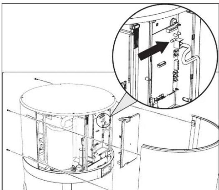
- Remove the top cover of the equipment and then the power board cover.
- Remove the fuse cap, then the fuse, using a suitable screw-driver.
• Install a new IEC-60127-2/II certified time-delay 5 A fuse, then refit the protective cap. - Reassemble all the plastics and make sure the equipment is correctly installed before powering it.
natural_image
Technical line drawing of a mechanical assembly with an inset showing internal components (no text or symbols)fig. 40
8.2 Heating element safety thermostat reset
This equipment has a manual-reset safety thermostat connected in series with the heating element immersed in water, which interrupts the power supply in case of overtemperature inside the tank.
If necessary, proceed as follows to reset the thermostat (reserved for qualified technical personnel):
- Unplug the product.
- Remove any air ducts.
- Remove the top cover by first undoing the locking screws (fig. 41).
- Remove the front panel and manually reset the tripped safety thermostat (fig. 42). In case of intervention, the central pin of
the thermostat comes out by about 2 mm.
- Refit the previously removed top cover.

natural_image
Technical line drawing of a cylindrical industrial device with two circular vented ports and internal components (no text or symbols)fig. 41 - Top cover removal

natural_image
Technical line drawing of a mechanical assembly with internal components and an inset view showing a component being inserted (no text or symbols present)fig. 42 - Front panel removal

ATTENTION!: Intervention of the safety thermostat can be caused by a fault linked to the control board or by no water inside the tank.

ATTENTION!: Carrying out repair work on parts with safety function compromises safe operation of the equipment. Replace faulty parts with original spare parts only.

NB!: Intervention of the thermostat excludes operation of the heating element but not the heat pump system within the permitted operating limits.

ATTENTION! If the operator is unable to eliminate the fault, switch off the equipment and contact the Technical Assistance Service, communicating the model of the product purchased.
9. MAINTENANCE

ATTENTION!: Any repairs to the equipment must be carried out by qualified personnel. Improper repairs can put the user in serious danger. If your equipment needs any repair, contact the service center.

ATTENTION!: Before undertaking any maintenance operation make sure the equipment is not and cannot accidentally be electrically powered. Therefore, disconnect the power at every maintenance or cleaning operation.
9.1 Sacrificial anode check/replacement
The magnesium (Mg) anode, also called "sacrificial" anode, prevents any eddy currents generated inside the boiler from triggering surface corrosion processes.
In fact, magnesium is a weakly charged metal compared to the material of which the inside of the boiler is coated, therefore it attracts first the negative charges that form with the heating of water, consuming itself. The anode therefore "sacrifices" itself by corroding itself instead of the tank. The boiler has two anodes, one fitted in the lower part of the tank and one fitted in the upper part of the tank (area more subject to corrosion).
The integrity of the Mg anodes must be checked at least every two years (preferably once a year). The operation must be performed by qualified personnel.
Before doing the check:
- Close the cold water inlet.
- Proceed with emptying the boiler (see par. "9.2 Boiler emptying").
- Unscrew the upper anode and check its corrosion; if the corrosion affects more than 2/3 of the anode surface proceed with replacement.

natural_image
Line drawing of a cylindrical industrial device with two vented chambers and a handle (no text or symbols)fig. 43
The anodes have a special sealing gasket, to prevent water leaks; it is advisable to use anaerobic thread sealant compatible for use in heating-plumbing systems. The gaskets must be replaced with new ones in case of checking and also anode replacement.
9.2 Boiler emptying
If not in use, especially in case of low temperatures, it is advisable to drain the water inside the boiler. For the equipment in question, just open the drain cock as per the example hydraulic connections chap. "Plumbing connections" on page 78 (see fig. 16).

NB!: In case of low temperatures, remember to empty the system to avoid freezing.
10. DISPOSAL
At the end of use, the heat pumps must be disposed of in compliance with current regulations.

ATTENTION!: This equipment contains fluorinated greenhouse gases included in the Kyoto protocol. Maintenance and disposal operations must be carried out only by qualified personnel.
INFORMATION FOR USERS

Pursuant to Directives 2011/65/EU and 2012/19/EU on the restriction of the use of hazardous substances in electrical and electronic equipment, as well as the disposal of waste.
The crossed-out bin symbol on the equipment or on its packaging indicates that, at the end of its useful life, the product must be collected separately from other waste.
Therefore, at the end of its life, the user must give the equip-
ment to the appropriate recycling centers for electrical and electronic equipment, or return it to the dealer when purchasing new, equivalent type equipment, on a one-to-one basis.
Adequate separate waste collection for subsequent sending of the decommissioned equipment to environmentally compatible recycling, treatment and/or disposal helps prevent negative effects on the environment and health and favors the reuse and/or recycling of the materials that make up the equipment.
Unauthorized disposal of the product by the user involves the application of the administrative sanctions provided for by current legislation.
The main materials that make up the equipment in question are:
- steel
- copper
- magnesium
- aluminum
- plastic
- polyurethane
11. PRODUCT SHEET
| Descriptions u.m. 200 HT 260 HT | |||
| Declared load profile L XL | |||
| Energy efficiency class for heating water in average weather conditions A+ A+ | |||
| Energy efficiency of water heating in % in average weather conditions % 116 127 | |||
| Annual energy consumption in kWh in terms of final energy in average weather conditions | kWh | 883 | 1315 |
| Water heater thermostat temperature settings | °C | 55 | 55 |
| Inside sound power level Lwa in dB | dB | 52 | 52 |
| The water heater can only work during off-peak hours | NO | NO | |
| Any specific precautions to be taken at the time of assembly, installation or maintenance of the water heater | See manual | ||
| Energy efficiency of water heating in % in coldest weather conditions | % | 116 | 127 |
| Energy efficiency of water heating in % in hottest weather conditions | % | 116 | 127 |
| Yearly energy consumption in kWh in terms of final energy in coldest weather conditions | kWh | 883 | 1315 |
| Yearly energy consumption in kWh in terms of final energy in hottest weather conditions | kWh | 883 | 1315 |
| Outside sound power level Lwa in dB | dB | 50 | 50 |

FERROLI S.pA.
Via Ritonda 78/a
37047 San Bonifacio - Verona - ITALY
www.ferroli.com
Fabbricato in Italia - Fabricado en Italia - Made in Italy
- CE
- INTRODUZIONE......4
- SCHEDA PRODOTTO....33
- INTRODUZIONE
- CARATTERISTICHE COSTRUTTIVE
- Collegamenti remoti
- FICHA PRODUCTO....65
- INTRODUCCIÓN
- CARACTERÍSTICAS CONSTRUCTIVAS
- Modo Off-Peak HP HP HP
- INTRODUCTION......68
- HANDLING AND TRANSPORT ......69
- CONSTRUCTION CHARACTERISTICS....71
- IMPORTANT INFORMATION....74
- INSTALLATION AND CONNECTIONS ....75
- DESCRIPTION OF USER INTERFACE AND OPERATION OF EQUIPMENT 82
- COMMISSIONING....91
- TROUBLESHOOTING....94
- MAINTENANCE....96
- DISPOSAL....97
- PRODUCT SHEET ......97
- INTRODUCTION
- Products
- Disclaimer
- Copyright
- Available versions and configurations
- HANDLING AND TRANSPORT
- Receipt
- CONSTRUCTION CHARACTERISTICS
- NOTES
- IMPORTANT INFORMATION
- Compliance with European regulations
- Casing protection rating
- Operating limits
- Operating limits
- Temperature range
- Water hardness
- Basic safety rules
- Information on the refrigerant used
- INSTALLATION AND CONNECTIONS
- Preparation of place of installation
- Securing to the floor
- Aeraulic connections
- Special installation
- Securing and connections of EGEA
- Plumbing connections
- Legend (fig. 16)
- Condensate drain connection
- Electrical connections
- Remote connections
- INPUTS
- Remote connection
- DESCRIPTION OF USER INTERFACE AND OPERATION OF EQUIPMENT
- Turning the water heater on and off and unlocking the buttons
- Turning on
- Turning off
- Setting the clock
- Setting time bands
- Setting the hot water set-point
- Operating mode
- ECO
- AUTOMATIC
- BOOST
- ELECTRIC
- VENTILATION
- HOLIDAY
- Photovoltaic Mode HP for + oHP 🎨 ✿
- Off-Peak Mode HP or + HP 🎨
- Additional functions
- Anti-Legionella
- Defrost function
- Frost protection
- Control of equipment via APP
- User registration
- Faults/protection
- COMMISSIONING
- Query, editing operating parameters
- TROUBLESHOOTING
- Power board fuse replacement
- Heating element safety thermostat reset
- MAINTENANCE
- Sacrificial anode check/replacement
- Boiler emptying
- DISPOSAL
- INFORMATION FOR USERS
- The main materials that make up the equipment in question are:
- PRODUCT SHEET
Brand : FERROLI
Model : Egea Ht
Category : Instant water heater and water heater