
CCFL-4530 - Air conditioner Infiniton - Free user manual and instructions
Find the device manual for free CCFL-4530 Infiniton in PDF.


| Product Type | DC Inverter Ceiling & Floor Air-Conditioner |
| Model | CCFL-4530 |
| Brand | Infiniton |
| Cooling Capacity (Approx.) | 5.3 kW (18,000 BTU/h) |
| Heating Capacity (Approx.) | 5.9 kW (20,000 BTU/h) |
| Power Supply | 220-240 V ~ 50 Hz (Single Phase) |
| Refrigerant | R32 |
| GWP of Refrigerant | 675 |
| Dimensions (Indoor Unit) | 1245 x 680 x 244 mm (W x H x D) |
| Dimensions (Outdoor Unit) | 925 x 366 x 700 mm (W x H x D) approx. |
| Modes | Auto, Cool, Heat, Dehumidify, Fan Only |
| Fan Speeds | Auto, Low, Medium, High |
| Timer | 24-hour timer with On/Off setting |
| Remote Control | LCD remote with temperature display and mode selection |
| Swing Function | Up/Down and Left/Right auto swing |
| Additional Features | Turbo, Eco, Sleep, Light control |
| Installation Type | Ceiling, Floor, Embedded |
| Air Filter | Washable; clean every 2 weeks |
| Refrigerant Pipes | Flare connections; max length 15-50 m depending on capacity |
| Drainage | Requires proper drainpipe with downward slope |
| Safety Features | Overcurrent protection, compressor protection, anti-freeze, auto restart |
| Package Contents | Indoor unit, outdoor unit, remote controller, batteries, installation manual |
Frequently Asked Questions - CCFL-4530 Infiniton
User questions about CCFL-4530 Infiniton
0 question about this device. Answer the ones you know or ask your own.
Ask a new question about this device
Download the instructions for your Air conditioner in PDF format for free! Find your manual CCFL-4530 - Infiniton and take your electronic device back in hand. On this page are published all the documents necessary for the use of your device. CCFL-4530 by Infiniton.
USER MANUAL CCFL-4530 Infiniton
DC Inverter Ceiling & Floor Air-Conditioning Units
Instruction Manual
CCFL-4530
CCFL-6321
INFINITON
-
Original instructions for use with safety instructions.
-
This appliance is intended to be used by expert or trained users in shops, in light industry and on farms, or for commercial use by lay persons.
-
GWP: R410A: 2087.5 or GWP: R407C: 1773.9 .
-
This appliance is not intended for use by persons (including children) with reduced physical, sensory or mental capabilities, or lack of experience and knowledge, unless they have been given supervision or instruction concerning use of the appliance by a person responsible for their safety.
-
Children should be supervised to ensure that they do not play with the appliance.
-
The appliance shall be installed in accordance with national wiring regulations.
-
This appliance can be used by children aged from 8 years and above and persons with reduced physical, sensory or mental capabilities or lack of experience and knowledge if they have been given supervision or instruction concerning use of the appliance in a safe way and understand the hazards involved.
-
Children shall not play with the appliance.
-
Cleaning and user maintenance shall not be made by children without supervision.
-
Disconnect the appliance from its power source during service and when replacing parts.
-
Warning: before obtaining access to terminals, all supply circuits must be disconnected.
-
If the supply cord is damaged, it must be replaced by the manufacturer, its service agent or a similarly qualified person in order to avoid a hazard.
-
An all-pole disconnection switch having a contact separation of at least 3mm in all poles should be connected in fixed wiring.
-
Disconnect the power supply before cleaning and maintenance.
-
The appliance shall not be installed in the laundry.
-
F-Gas label:
The equipment contains fluorinated greenhouse gas R32
Global Warming Potential(GWP):675
17.

natural_image
Simple line drawing of a trash bin with crossed lines indicating no waste or discharge (no text or symbols)| Correct Disposal of this product | |
| This marking indicates that this product should not be disposed with household wastes throughout the EU. To prevent possible harm to the environment or human health from uncontrolled waste disposal, recycle responsibly to promote the sustainable reuse of material resources. I return your used device, please use the return and collection systems contact the retailer where the product was purchased. They can take a product for environmental safe recycling. |
Content
- Safety precautionary measure 1
2.Unit Introduction 3 - Introduction for Remote controller and Light Board 5
- Installation Guide 8
5.Electrical Installation 25
Appendix: Unit Packing List
- Please read this manual carefully before using the machine, and operate correctly in accordance with the guidance of the manual.
- You are particularly reminded to pay attention to the significance of the following two identities:


Note refers to as an identification which indicates that with improper operation, it may cause personal injury or serious damage.


Note refers to as an identification which indicates that with improper operation, it may cause personal injury or property damage.
Please carefully read the label on the main unit, if an exception occurs, such as abnormal noise, smell, smoke, temperature, leakage, fire and so on, please immediately turn off the power and timely contact our local customer service center or dealer. Never handle on one's own. If necessary, immediately contact the local fire and emergency departments.


- The appliance shall operate in a room without any continuously operating ignition sources;
-
Have to refer to the safety instruction before installing the appliance.
-
The system should be used in places like offices, hotels, homes and so on.
- The installation should be implemented by commissioned maintenance center. If improperly installed, it may cause water leakage, electric shock or fire accident.
- Install it in a place where the full weight of the machine can be really bear. Insufficient strength can cause device falling and lead to personal injury.
- Drainage pipes should be properly installed in accordance with the installation instructions to ensure proper drainage, and insulation measures should be taken to prevent condensation. If the pipe is not installed correctly, it will cause water leakage and there is a possibility of getting the household items wet.
- Do not use or store inflammable and explosive dangerous goods near the air conditioner.
- In the event of failure (such as burning smell, etc.), immediately turn off the air conditioner's power.
- Keep the room ventilated to avoid hypoxia.
- Never put your fingers or objects into the vents or air intake grille.
- Never start or stop the air conditioner by way of disconnect or plug in the power cord.
- Please always pay attention to whether there is a damage on the mounting bracket and so on after long-term use.
- Never be modified, repaired, and when moving the air conditioning is necessary, please contact your dealer or a professional installer.

Notice
- Before installation, please check that the power used is consistent with the power required on the nameplate, and check the safety of power supply.
- Before use, check and confirm that the connections between wires, pipes and tubing are correct, to prevent leakage, refrigerant leakage, electric shock or fire and other accidents.
- Power outlet must be equipped with ground wire, to ensure that the air conditioner is effectively grounded through the power outlet to avoid the risk of electric shock. Do not connect the ground wire to gas pipe, water pipe, lightning rod or telephone wiring.
- Once the air conditioner turned on, it has to run at least five minutes or more before it can be shut down, otherwise it will affect the compressor oil return.
- Do not let children operate the air conditioner.
- Do not operate the air conditioner when your hands are wet.
- When clean or replace the air conditioner filter, please turn off the air conditioner's power.
- When the main unit has not been used for a long time, please cut off the power supply of the air conditioner.
- Do not step on the air conditioner, or place objects on the air conditioner.
- After installation of electrical appliance, it should be powered to perform current leakage detection.
● Reusable mechanical connectors and flared joints are not allowed indoors.
Indoor unit:
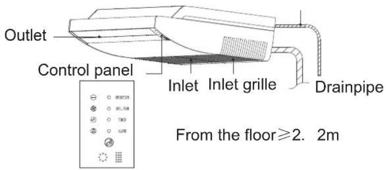

NOTE
● All figures in this manual are based on the appearance of the standard type unit, they are only used for application explanation, and the actual appearance refers to the model you bought.
Outdoor unit:
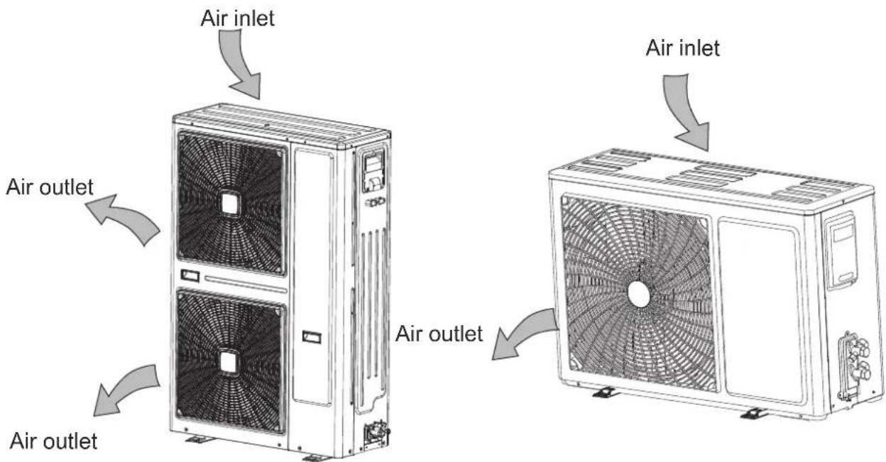
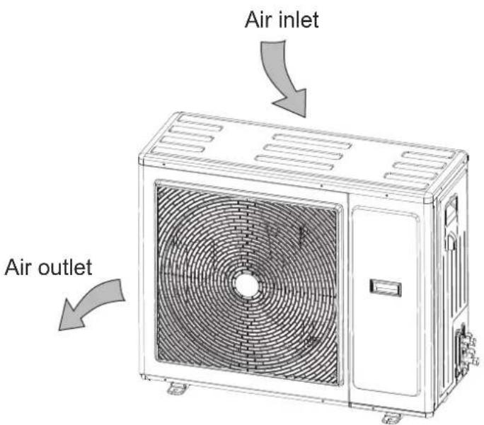
Note: The air conditioner consists of an indoor unit and outdoor unit, excluding air duct of connecting pipe.
Introduction for remote controller and light board (standard)
Indicator plate(light board must be used associated with remote controller)
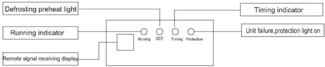
flowchart
graph TD
    A["Defrosting preheat light"] --> B["Running indicator"]
    C["Remote signal receiving display"] --> B
    B --> D["Running"]
    B --> E["DEF."]
    B --> F["Timing"]
    B --> G["Protection"]
    H["Unit failure,protection light on"] --> F
    I["Timing indicator"] --> F
Wizard universal remote controller (They can respectively be used associated with the remote controller or light board)
The following swing button, forced button, light button, purification button on the remote controller applies to new special models, but not applies to ordinary models.
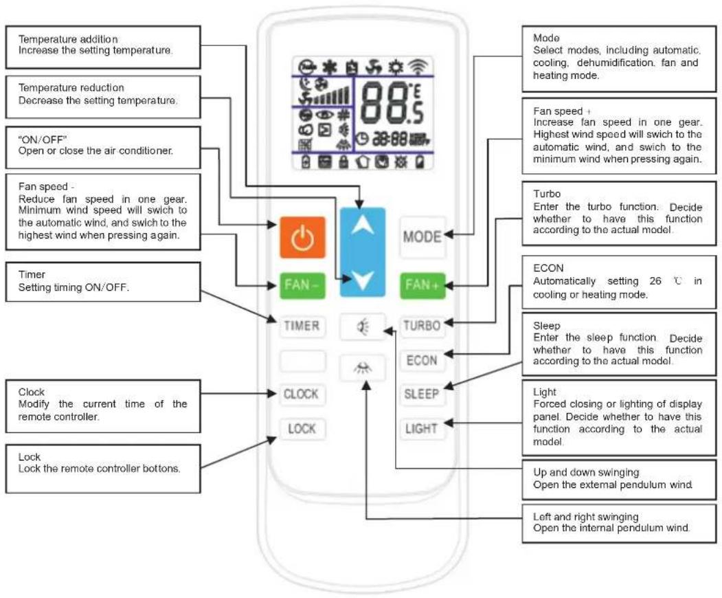
flowchart
graph TD
A["Temperature addition<br>Increase the setting temperature."] --> B["Mode<br>Select modes, including automatic, cooling, dehumidification, fan and heating mode."]
C["Temperature reduction<br>Decrease the setting temperature."] --> B
D[""ON/OFF"<br>Open or close the air conditioner."] --> B
E["Fan speed -<br>Reduce fan speed in one gear.<br>Minimum wind speed will switch to the automatic wind, and switch to the highest wind when pressing again."] --> B
F["Timer<br>Setting timing ON/OFF."] --> G["FAN-"]
G --> H["MODE"]
G --> I["FAN+"]
H --> J["TURBO"]
I --> K["ECON"]
J --> L["SLEEP"]
K --> M["LIGHT"]
N["Clock<br>Modify the current time of the remote controller."] --> O["CLOCK"]
P["Lock<br>Lock the remote controller bottoms."] --> Q["LOCK"]
R["Mode"] --> S["Mode"]
T["Fan speed +"] --> U["Fan speed +"]
V["Turbo"] --> W["Turbo"]
X["ECON"] --> Y["ECON"]
Z["Sleep"] --> AA["Sleep"]
AB["Light"] --> AC["Light"]
AD["Up and down swinging"] --> AE["Up and down swinging"]
AF["Left and right swinging"] --> AG["Left and right swinging"]
On / Off button: when press the button, the remote controller is cycling switched following "open → closed → open". When you first power up from Off → On, the working status remains on default setting (Temperature setting 25°C, Auto mode, Auto wind speed, Auto swing, Auto throttle, No lights, No strong wind, No purification, No sleep, No timer, No lock button). None-first time when power on from Off → On, the working state remains the state before shutdown. after shutdown functions of lighting, purification, sleep, strong wind and timing will be cancelled.
Mode key: when pressing mode key, the remote control cycling switches according to the "automatic →cooling → dehumidification→ heating→ventilation → automatic".
Increase button: on dehumidification mode and auto mode, the temperature will not change when this button is pressed. In the other mode, each press of this button will plus 1 on the set temperature, increments occur in order of "16°C → 17°C → ... → 31 °C → 32 °C".
Wind direction button: wind direction on the first power on is defaulted for the swing state, when press this button, the unit is cycling switched following "swing → stop → swing".
Wind speed button: on the first power on, wind speed is defaulted for auto wind speed, when in dehumidification mode, wind speed is fixed at low wind, and the wind speed can not be adjusted, when press wind speed button the remote controller does not respond. For the other modes, when you press this button, it is cycling switched following "Auto wind → High wind → Middle wind → Low wind → Auto wind".
Timer button: it is defaulted for no timer state, when press this button, the timer setting is performed in one hour increments, the timer is set in order of 1H 2H 24H cancel 1H cycle. Press the timer button in the Off state to set On, in the power on state, press timer button to set the timer switch. When the timer is set, every one hour minus one, and power on or shut down until the time runs out, while closing the timer display. If the timer is set, when press the mode button, the time setting will not be canceled. If the timer is set, pressing on another button will release the time set on the timer.
Sleep button: press sleep button, it is cycling switched following "sleep → cancel sleep → sleep", when sleep is set, after the conversion of mode, the sleep is not canceled. When press sleep button to set sleep, wind speed is automatically switched to low wind, but by pressing the wind speed button it is possible to adjust the wind speed (except dehumidification mode).
Lock button: it is defaulted for no lock button status, when press this button, the remote controller is cycling switched following "lock button → cancel Lock button → lock button". When there is a lock button, all buttons except the lock button of the remote controller do not work. (Note: When there is a lock button, the button on the remote controller and the air conditioner operate plate of standby unit are automatically locked, when press this button again, the remote controller and the air conditioner will all be automatically unlocked. in discrete unit, only the remote controller is locked, the emergency button will not be locked, but the main plate response.)
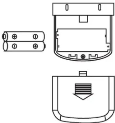
Replacement of the battery of remote controller
After signal being transferred or sending, no receiving sound will be sent out in the air conditioner; indicator get blurred.
From above it indicates the battery is depleted, now you should remove the old battery, and replace with a new battery:
1) Remove the rear cover, and remove the old battery;
2) Replace the battery, note the marking on the battery "+",-" pole;
3) Close the rear cover.
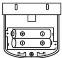
natural_image
Diagram of a battery pack with two cylindrical cells and terminal blocks (no text or symbols)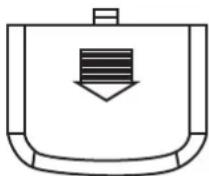
Remove the back cover
Note:
- Do not mix old and new batteries.
- If the remote controller has not been used for a long time, please remove the battery.
- Under normal conditions, the service life for batteries which comply with JIS or IEC standards is 6-12 months, if the time limit for using is exceeded, or batteries of non above specifications is adopted, it may produce exudate cells, making it impossible to perform remote control operation.
natural_image
Technical line drawings of three electronic components: battery pack, internal casing, and cover (no text or symbols)Note the alignment of "+", "-" pole
■ To ensure the installation is correct, you must read the "INSTALLATION" in this manual.
■ After installation, the installer should explain the correct operation and maintenance method (base on the manual) to the user, tell him/her to read and keep the INSTALLATION AND OPERATION MANUAL carefully.
■ The warnings in this manual are all very important about safety, please be sure to comply.

WARNING
- Please entrust the local dealer or the local service point to arrange someone who has the air conditioner installation permit to take the installation. Forbid users to install it without permission.
- Please refer to this manual strictly to install the air conditioner.
- Please be sure to use the accessory in this unit and the specified component parts.
- Please install on somewhere that can sustain the air conditioner.
- Please refer to this manual and wiring specification of national electric equipment or base on actual operation specification to construct the electric equipment.
- Please be sure to use the specified wires, forbid to share the same wire with other equipment.
- Forbid to use the wire which has plug in the middle. Forbid to use extension cord. Forbid to connect other load.
- Be sure to use the specified cable to connect the indoor and outdoor units.
- When connecting the indoor and outdoor units, please neatly put away the cable to avoid unnecessary external force to the units.
- During the air conditioner installation or moving, please do not fill air (or other mixture gas) into the cooling system except the specified refrigerant.
- If refrigerant leakage occurs during the installation, please take the ventilation.
● After installation construction, please make sure no refrigerant leakage.
● Make sure the air conditioner has correct and reliable grounding.
◆Select the installation location for the indoor unit
■Please install on the location that meets the following conditions and has the permission from user.
●No thermo source and steam source around the installation location.
●No obstacle which will hinder air circulation at the installation location.
- Somewhere that has good air circulation and both cool & hot air within reach.
●Somewhere that is convenient to drain.
- Somewhere that the ceiling is flat and the structure must be able to sustain the weight of the indoor unit, and do not increase the running noise and strengthen the vibration.
- Somewhere that has the conditions of installation and repairing.
- Somewhere that is convenient to fix pipe and put out wires.
●Somewhere that avoids lampblack.
- Keep distance of 1 meter at least from TV, audio devices etc.
- Select the location that is easy to drain condensate, and easy to connect outdoor unit.
- Keep far away from flammable materials, such as curtain, clothes especially.
◆ Select the installation location for the outdoor unit
Please install on the location that meets the following conditions and has the permission from user.
- Somewhere that the noise and airflow from the discharge does not affect neighbors.
●Good ventilation, make sure the outdoor unit has good ventilation.
●Meet related requirements of environmental protection and cityscape and firefighting.
● No obstructions to hinder the inlet and outlet of the outdoor unit.
●Installation location should be able to withstand the weight of the outdoor unit and its vibration, in order to avoid noise and vibration enlarging in the transmission. Also it should be safe for installation construction. The mounting surface must be reinforced concrete structures or equivalent structures. The material and structure design and manufacture of mounting bracket should fully consider the load-bearing strength, corrosion resistance, and it should be convenient for fixing. Iron/steel components should be securely welded or connected and rust treated. The loading capacity of outdoor unit mounting surface (mounting bracket) should not less than at least 200 kg. - For hanging installation, the mounting surface should be solid bricks, concrete or the equivalent strength structure with sufficient loading capacity, otherwise you should take reinforce, bracing, vibration reduction and other measures. The connecting between mounting surface and mounting bracket, mounting bracket and air conditioner should be secure, stable and reliable, make sure the air conditioner is installed without sliding, overturning and falling down.
●Somewhere that has no leakage of flammable or corrosive gases. - Installed in the following places may cause malfunctions of the air conditioner. If it is unable to avoid, please contact the service point.
◇ Somewhere that has machine oil
◇ Saline areas in the seaside
◇ Somewhere that has sulfur-containing gases (such as sulfide hot spring)
Somewhere that has frequency conversion facilities, such as RF facilities, welder machines, medical equipments, that radiates strong EMI.
◇ Avoid installing to the side that has heavy sandstorm, smoking from factories, strong sea wind.
◇ Special surrounding conditions.
- Choose somewhere that there is no rain, no direct sunlight and also good ventilated place as far as possible. If it is unable to avoid, you should make a shelter, but pay attention to the condenser heat dissipation, it must not be hindered.
●The installation location should be better not rearing animals or planting trees or flowers.
- Please avoid the location that may has flammable or explosive gas leakage.
●Convenient to install and operate, avoid strong wind, and also dry and good ventilated.
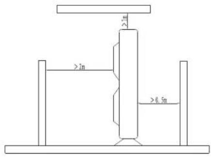
●The main requirements of spatial position to install outdoor unit:
Left ≧ 30 cm, right
60 cm, back
30 cm, front
200 cm
◆Electrics installation requirements
■ For the first installation
- If the users' electrical environment has serious risks, the installer should refuse to install, and explain the reasons. Install after removing the risks.
●The power supply voltage must be within the range of 10%. If not, some rectification measures should be taken.
●The line should be equipped with a leakage protector and a master switch. Forbid to exchange the fuse with copper wire or others. To select the correct fuse, it should base on 1.5 to 3 times of the maximum power of the air conditioner (connected to the line) and add the sum of the maximum current from other electrics.
●The user's power lines should have grounding wire, if no grounding wire, installer should refuse to install, and explain the reasons.
●The power supply to air conditioner must use the specified branch line. Power delivery must meet the following requirements:
Table for Wire Cross-sectional Area (Diameter) and Switch (Socket) and Fuse Size and Load Current Comparison
| The specified power delivery device and wires for air conditioner | Power delivery device and wires for power bus | ||||
| The maximum current(A) | Wire cross-sectional area (mm square) | Socket or switch/ fuse nominal specification (A) | The maximum current of lines (1.5-3)(A) | Wire cross-sectional area (mm square) | ≤ Switch/fuse normal specification (A) |
| ≤ 10 | 1 or 1.5 | 16 / 16 | ≤ 16 | 1.5~4 | 32 / 25 |
| ≤ 16 | 1.5 or 2.5 | 32 / 25 | ≤ 25 | 2.5~4 | 63 / 50 |
| ≤ 25 | 2.5 or 4 | 63 / 50 | ≤ 32 | 4~10 | 63 / 50 |
| ≤ 32 | 4 or 6 | 63 / 50 | ≤ 40 | 6~16 | 100 / 80 |
| ≤ 63 10~25 | 125 / 125 | ||||
NOTE: The maximum current of air conditioner is the maximum output current value written on the nameplate of indoor unit. The maximum current of lines is the maximum current of the air conditioner plus the maximum current from other electrics.
■ During installation construction
- The connecting power cable between indoor and outdoor units (including high voltage signal wire) must use chloroprene rubber cable, forbid to use PVC cable. Forbid to lengthen or cut short the cable. For the excess power cable, it should be roundly collated, forbid to twine it to small circles.
● Grounding wire should use the yellow/green wire, and has sufficient diameter. Forbid connecting grounding wire to running water pipe or gas pipe or power lines or lightning line.
For wiring, you must refer to the wiring diagram pasted on the unit, and make sure the parts are correct and then to connect.
- For wiring, each wire end must press the U-type terminal as required before it is connected to the terminal blocks. The U-type terminal must firmly connect to the wire.
4. 1 Indoor unit installation
◆Brief diagram for installation
For the three directions of A, B, C, make sure at least two directions are unobstructed.
When outdoor unit is installed higher than indoor unit, in order to avoid water get into the room from the connecting pipe, you should make a curved bend (the curve face down) at the connecting pipe before it gets through the wall to the indoor room, make sure the vertex is at outdoor.
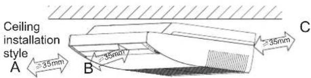
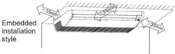
◆ Make a hole on the wall
① Select the right installation location
② Determine the pipe fixing up direction and pipe out go position
③ Select the drill size base on the unit model, use electric hammer or water-driller to make hole on the wall.
■ Generally, the recommended hole size is 90 mm.
For holes drilling, to avoid the wall which part is too hard, or wires/other objects at indoor or outdoor. The indoor side of the hole should be
higher than 0.5cm - 1cm of the outdoor side, in order for drain convenience. If the hole
besides the indoor unit, it should be a little lower than the bottom of indoor unit. If you make this hole with a water-driller, a plastic cloth should be posted on the wall or make other measures to avoid water from running to else part. If you use the electric hammer, you should take measures to avoid dust.

◆ Install the main body
①Install the Φ10 lifting bolts (4 in total)
②Processing of the ceiling will be different base on different buildings. It should be consulted with the building renovation staff to get the detailed measures.
◎Processing of the ceiling: To make sure the ceiling is horizontal and without vibration, the ceiling racks must be reinforced.
◎ Reinforce the cut part of the ceiling, and reinforce the girders.
③After the main body is well hung, constructing the pipes and wiring is followed. Determine the pipe leading out direction after selecting the installation location. Especially in the case of existing ceiling, please pull the refrigerant pipe, drainpipe, cables for indoor and outdoor units, controlling wire to the connecting position, before hanging the unit.
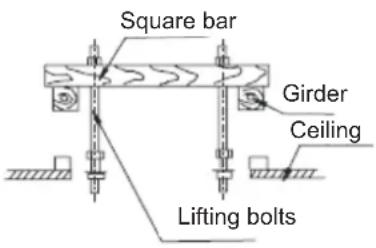
④The fixing method of lifting bolts
Matching the current structure, set the thread pitch based on the size of this unit as follows.
● Wooden occasions
Put the square bar on the girders to set the lifting bolts
● Steel skeleton occasions
Set and directly use the supporting angle steal
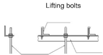
Hanging-lifting bolts
Supporting angle steal
● ● Original concrete embryo occasions New concrete embryo occasions
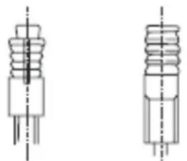
natural_image
Pure technical line drawing of two mechanical components with no text or symbols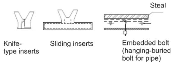
⑤Floor installation method
Please use the embedded bolts, or expandable bolts etc.
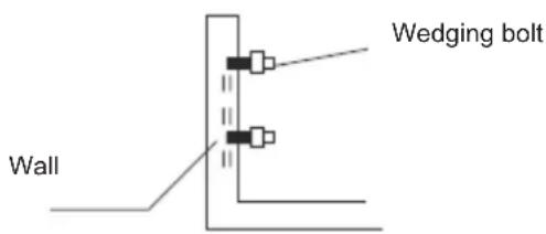
●The material of bolts is high-quality carbon steel (surface with copper plating or other rust treatment) or stainless steel.
- Processing of the ceiling will be different base on different buildings. It should be consulted with the building renovation staff to get the detailed measures.
●The fixing of lifting bolts are depended on detailed condition, but be sure to fix reliably.
◆ Indoor unit installation
■ Lift the indoor unit to the lifting bolts with pulleys or other equipment. Install the indoor unit horizontally with the horizontal instrument. If it is not installed horizontally, water leakage may occur.
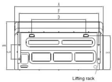
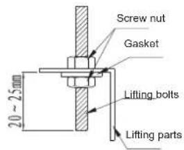
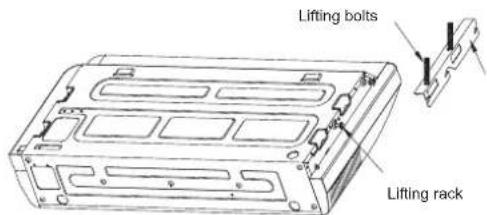
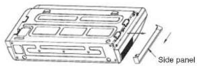
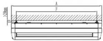
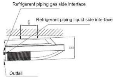
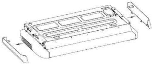
The installation steps of embedded style is basically the same with the hanging style, but you should make holes on the ceiling before installation, the hole size is 1 170 6 10. Take away the left and right panels of the indoor unit, and then embed half of the unit body into the ceiling, only show up the back panel and top panel.
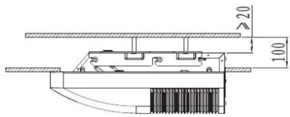
natural_image
Technical line drawing of a mechanical component with internal channels and mounting brackets (no text or symbols)For the floor installation style, install the indoor unit horizontally with the horizontal instrument, the unit body keeps vertical to the floor.
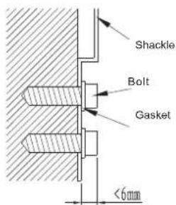
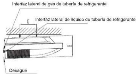
Unit: mm
| Model Liquid pipe Gas pipe A B C D E | F G H | |||||||||
| 18K | 6.35 | 12.7 | 1245 | 680 | 244 | 760 | 450 | 1119 | 200 | 240 |
| 24/36K | 9.52 | 15.88 | 1245 | 680 | 244 | 760 | 450 | 1119 | 200 | 240 |
| 48/55K | 9.52 | 15.88 | 1670 | 680 | 244 | 760 | 450 | 1542 | 200 | 240 |
◆Piping and banding
- Piping and banding
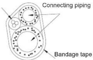
①Band the power cables, the signal wires and the connecting pipe.
② Adjust the positions for in-piping and out-piping according to the wall-hole position. Determine the pipe outing style.
③ The banded pipe should insert from the outdoor side through the wall-hole to the indoor side. It is must be carefully to do the piping, without damaging the pipe and the thermal insulation layer.
During the banding, do not pull the snake-shape pipe too hard.
◇ It should avoid banding the joints of connecting pipe, just for the leakage check.
During the pipe bending, cut off the needed irregularity on the heat insulation sleeve in the bend point, and then show up the pipe (band it with the bandage after bending). The radius of the bend should be as big as possible, to avoid reshaped or pressed bad.
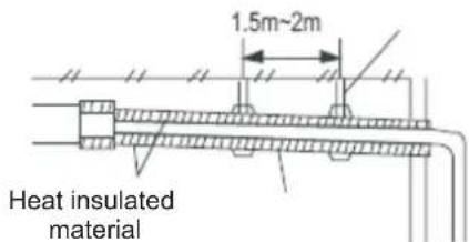
◇Stretching the pipe, use the vinyl tape to fix 5 to 6 positions.
◇ Under the occasion of laterally extract the pipe, it should cover the heat insulation material.
Connecting cable
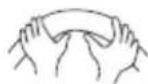
Bent the pipe with the thumb
The minimum radius 100 mm
- Connecting pipe
Tear out 10cm-15cm of the thermal insulation sleeve in out-pipe and in-pipe of indoor unit, make it convenient for pipe connecting. Firstly, connect the low-pressure pipe, and then the high-pressure pipe. Press the tapered surface of the pipe to the connector vertically, twist the connectors to the bottom of the bolt, and then fix it tight with a torque wrench.
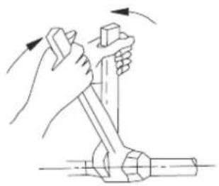
natural_image
Illustration of hands using a tool to lift a cylindrical object, showing motion arrows (no text or symbols)| Outside diameter of the copper pipe (mm) | Tightening torque(N·cm) | Reinforce tightening torque(N·cm) |
| Φ6.3 or Φ6 | 1570(160kgf·cm) | 1960(200kgf·cm) |
| Φ9.52 or Φ9 | 2940(300kgf·cm) | 3430(350kgf·cm) |
| Φ12.7 or Φ12 | 4900(500kgf·cm) | 5390(550kgf·cm) |
| Φ16 | 7360(750kgf·cm) | 7850(800kgf·cm) |
| Φ19 | 9720(900kgf·cm) | 11860(1210kgf·cm) |
◆ Install the drainpipe
When delivery, the outfall is PVC pipe, when connecting, please use the subsidiary of sealing materials and sleeve.
- Be sure to take the heat insulation of drainpipe of the indoor unit, if no heat insulation, it will have the condensate. The connecting part of indoor unit also needs heat insulation.
- Connecting the drainpipe, it should use the rigid PVC adhesive, and make sure there is no water leakage phenomenon.
Tilt down for above 1/100
●Note that it should not make the connector between the drainpipe and outfall of indoor unit to sustain any external force, include the weight of water pipe.
●The drainpipe to tilt down is above 1/100, it should be no bend in the middle.
●The lateral pull out of the drainpipe should be within 20 m. When the drain pipe is longer, please make the rack for support to prevent bending.
●The cut-connect interface of the drain system must be sealed to prevent water leakage.
●The end of drainpipe should have a distance of above 50 mm to the ground or the bottom drainage channels, and it should not put into the water. When the condensate is directly discharge to the stinking ditch, be sure to make a U-bend to form a water seal, in order to avoid stink getting into the room through the drain pipe.
- For the hanging installation construction, and drain pipes from many units are centralized constructed, it should provide a U-bend at the branch pipe of each unit, to prevent water refluxing from the main drain pipe.
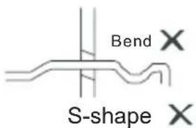
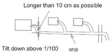
4.2 Installation of outdoor unit
A. Overall dimensions diagram for the outdoor unit
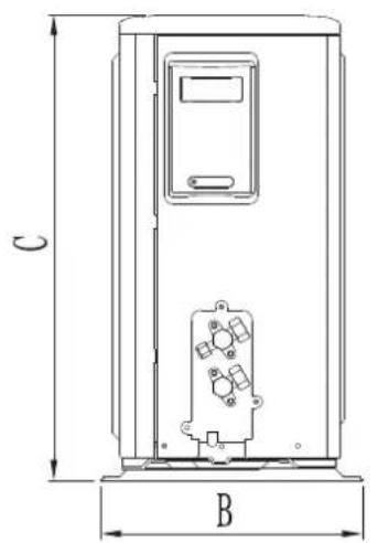
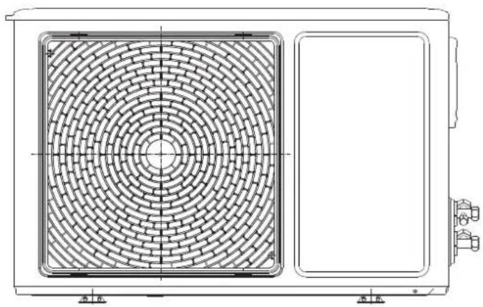
natural_image
Technical line drawing of a dual-panel air conditioning unit with circular vented structure (no text or symbols)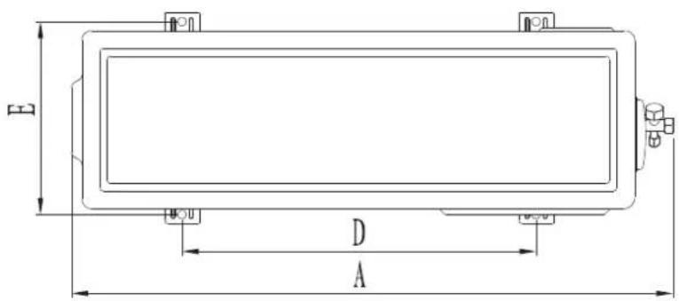
Unit: mm
| Machine capacity\Project | A B C | D | E | ||
| 18K | 925 36 | 6 700 590 | 340 |
B. Overall dimensions diagram for the outdoor unit
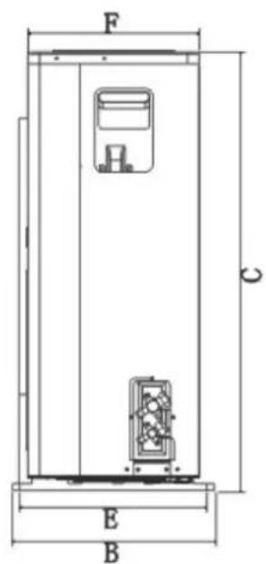
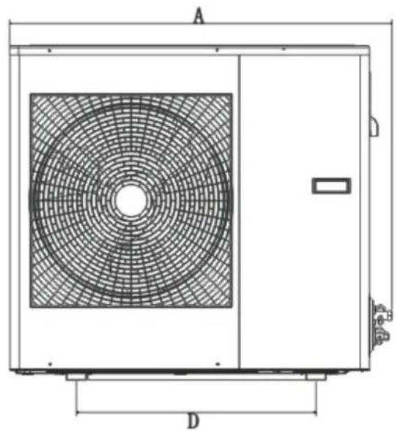
natural_image
Technical line drawing of a rectangular industrial air conditioning unit with circular fan pattern and labeled dimensions A and D (no text or symbols beyond labels)Unit: mm
| Machine capacity\Project | A FB C D E | ||||
| 24K | 958 39 | 2 843 600 | 360 330 |
C. Overall dimensions diagram for the outdoor unit
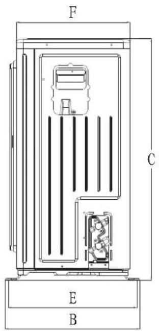
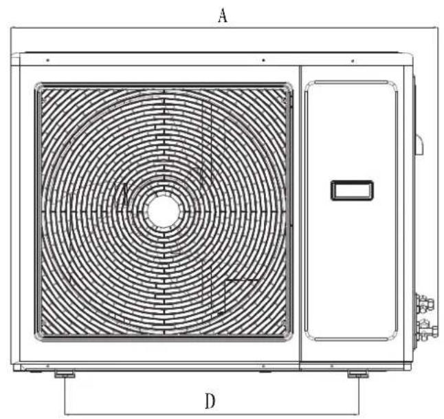
natural_image
Technical line drawing of a large air conditioning unit with circular fan pattern and control panel (no text or symbols)Figure 12.1
Unit: mm
| Machine capacity\Project | A | FB C | ||||
| 36K | 1030 43 | 2 788 707 | 389 370 |
D. Overall dimensions diagram for the outdoor unit
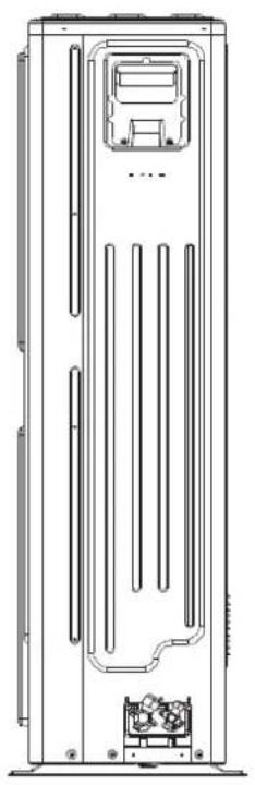
natural_image
Technical line drawing of a vertical cabinet or enclosure with internal compartments and mounting feet (no text or symbols)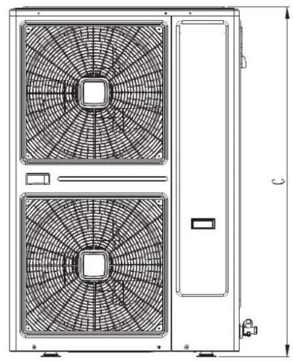
natural_image
Technical line drawing of a dual-panel HVAC unit with fan blades and door, showing top and side views (no text or symbols)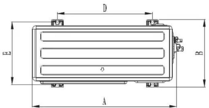
Figure 12.2
Unit: mm
| Machine capacity\Project | A | B | C | D | E |
| 48K 55K | 966 450 | 1430 636 | 416 |
E. Install dimension requirements for outdoor unit
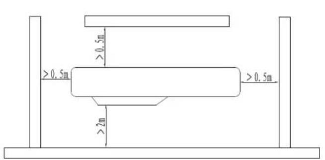
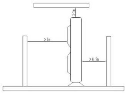
In order to ensure the unit to run well, in the choice of installation location, the following guidelines must be followed:
- Upon installation of the outdoor unit, the air discharged outdoor should not return, and enough space for maintenance must be remained around the machine.
- The ventilation must be excellent in mounting points, so that the machine can intake and discharge sufficient air. Make sure there are no obstacles for air inlet and outlet; if exist, remove obstacles which block the air flow.
- The installation location is strong enough to withstand the weight of the outdoor unit, and has the effect of sound insulation and vibration reduction. And to ensure that outlet air and noise of the unit will not affect the neighbors.
- Avoid direct sunlight, it's best to put up an sunshade for protection.
- In the mounting position, rain and defrost water must be drained.
- In the installation position, it must be ensured that the machine will not be buried in the snow, and not subject to the effects from garbage and mists.
- In the installation position, it must be ensured that the air outlet is not facing the strong wind.
4.3 Lifting of equipment
Before shipping, each air conditioner unit has been a rigorous inspection and testing, to ensure the quality and performance of the unit, and therefore care must be taken during installation of the device, especially not damage the control system and the pipeline.
During on-site installation, there are differences between the left and right in indoor, outdoor unit. With large size or space restrictions in indoor, outdoor unit, and hard to carry, the way of lifting can be considered.
General requirements during lifting:
- Inclination of outdoor unit should not exceed 20 degrees.
- During lifting, force is applied to the device, the device must be separated from hoisting rope with a cloth or other flexible objects to avoid damage to the device.
- During lifting, the equipment must be carefully lifted or lowered, the force on the stress points of the device must be uniform.
During lifting of the equipment, refer to the following methods:
- Manual lifting, forklift lifting.
-
The device can also be moved using the methods of logs (or pipes), labor goes on and so on.
Fixation of equipment. After the completion of equipment lifting, the next step must be carried out: -
When the device is lifted onto the foundation, Equipment levelness is adjusted with a level meter, the error does not exceed 0.1%.
-
When the equipment is put down evenly, the device can be fixed, and the force exerted on the fasteners must be uniform.
4.4. Connection and installation of indoor, outdoor unit refrigerant pipe
1. Pipeline inspection
Before connecting the pipes, they must be checked, and be installed after meeting the following requirements.
1) Inside the tube it must be clean and free of dirt.
2) Bell port and spiral port on both ends must be intact.
2.Pipe connections
On operation of connecting the condenser tubes of the indoor unit, the operation is required to be done quickly.
During field installation, operation time for connecting two tubes should not exceed 5 minutes.
1) When connecting the connector on the bell port, be sure to make two pipes concentric and aligned, and then nested the spiral port, and screwed it in, finally tightened with a wrench, shown in figure below:

Figure 15
Notes:
Use two wrenches, ordinary wrench, torque wrench each one.
Connect the solid brass, before operation, regulate the torque wrench according to tightening force parameters listed in Table below.
| Pipe diameter(mm) | Tightening force (kgf • m) |
| 6.35 | 1.4 ~1.7 |
| 9.52 | 1.4 ~1.7 |
| 12.7 | 4.8 ~6.2 |
| 15.88 | 4.8 ~6.2 |
| 19.05 | 6.9 ~9.9 |
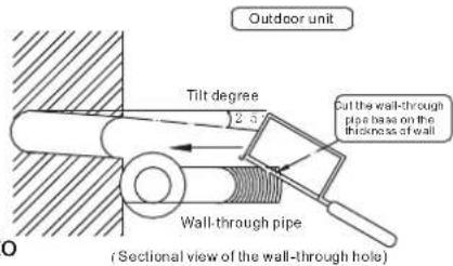
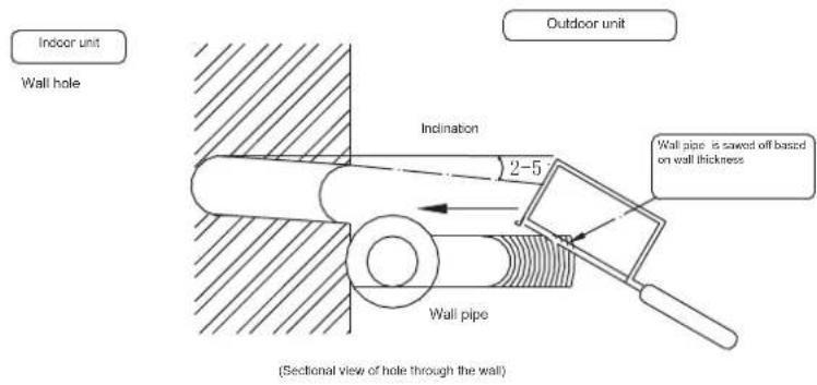
2) Through the wall: upon the wall penetration, the pipeline for indoor and outdoor unit must be equipped with wall cannula, to avoid damage of pipes and wires, as shown in Figure below:
3) Eliminate the negative pressure, evacuation, leaks in the connecting pipe, pipeline of indoor unit: After installation of the unit connecting pipe and the indoor unit, first fill nitrogen into the connecting pipes and the indoor unit pipe up to 2.4-3.0Mpa (absolute pressure); and maintain this pressure for 24 hours, the change of this pressure should not be less than 0.03Mpa; Also check with soap bubbles for any leaks on the connecting head and the welding position, the nitrogen is discharged after confirmation of no leakage, after evacuated, the pressure should reach 130Pa (absolute pressure), and maintain this pressure for 24 hours, the variation of this pressure should not be greater than 20Pa, then open the valve to perform a trial run, if the parameters of the condenser exceeds conventional regulations it needs additional R410A of refrigerant, the following methods can be referred to:
$$ R = \boxed {\left( \begin{array}{l} \text { Total length of } \ \text { liquid pipe for 9.5 } \ \text { diameter(m) } \end{array} \right) \times 0. 0 2 4 \mathrm{kg}} + \boxed {\left( \begin{array}{l} \text { Total length of } \ \text { liquid pipe for 6.4 } \ \text { diameter(m) } \end{array} \right) \times 0. 0 1 2 \mathrm{kg}} $$
Note: Upon sipping of the outdoor unit, the refrigerant has not been emptied, during installation, it should be evacuated with vacuum pump.
4) Thermal insulation. After leak check of the pipeline and completion of the pressure test, and everything is normal, the insulation layer can be wrapped, the requirements of the insulation layer is as following:
a. Piping insulation layer must be tightly wrapped, no crack is allowed.
b. Thickness not less than 8 mm.
c. After wrap of the insulation layer, the outer surface must be treated against rain, moisture (generally wrap outside with cable ties).
d. When the air conditioner system is in cooling run, dew is definitely not allowed to be condensed on the outer surface of the connecting copper pipe.
4.5 Accessory pipe in the pipeline
Because of different mounting positions of the air conditioning, the required accessory pipe can be long or short, to avoid affecting the amount from too long cooling pipe, please select a reasonable tube length according to table below, try to select the location of the short lines for the installation.
- The maximum allowable operating distance away from the pipe
| Value\Rated refrigerating capacity | <6.5kW | 6.5~7.2kW | ≥10.5kW |
| A Pipeline length (one-way) | Maximum length 15m | Maximum length 20m | Maximum length 50m |
| B Height difference(one-way) | Maximum length 8m | Maximum length 10m | Maximum length 20m |
| C Pipeline bends quantity | Up to 10 | Up to 10 | Up to 15 |
Note: On condition that 80% of the cooling capacity is guaranteed, in the above parameters, the cooling capacity loss and return oil has been fully considered.
2. The use of oil return elbow
When the height difference between the indoor and outdoor unit is greater than 5 m, in order to facilitate oil return of the compressor, oil return elbow must be used. Upon site operations, the following typical installation methods can be referred to (see Figure below).
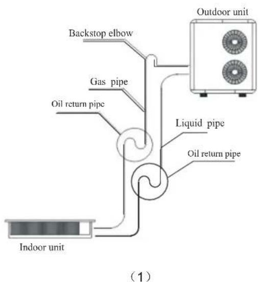
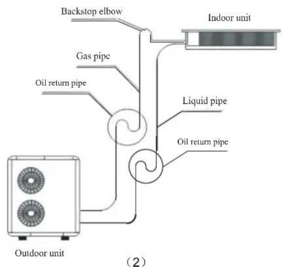
Note: Oil return elbow radius R ≤ 100mm , 10 oil return elbows must be located per 5m as shown above; when the height difference between indoor and outdoor unit exceeds five meters, oil reserve elbow and backstop elbow should be set according to the relative position of outdoor unit and indoor unit.
5.1 Connection of wires and terminal blocks

Notice
Before performing the installation of electrical equipment, our design staffs remind you to note the following:
- Check if the power currently used is consistent with the power supply indicated on the nameplate.
-
To ensure that the power supply capacity is large enough, and the cross-sectional area of the room wiring should be greater than 2.5mm^2 .
-
Lines must be installed by professionals.
-
Leakage protection switch and air switch in which the spacing of the electrode contacts is larger than 3 mm must be installed in fixed lines.
-
Connection of single branch line
(1) The end of the insulating layer of single branch line is stripped of about 25 mm by a stripper.
(2) Remove the screws on the terminal block A of the air conditioner.
(3) Use pliers to bend the end of single branch line to a ring which size matches that of the screw.
(4) Passing the screw through the ring on the single branch line, and fixed it on the terminal blocks.
- Connection of multi-stranded wire
(1) The end insulating layer of multi-stranded wire is stripped about 10mm by a stripper.
(2) After the wire be stripped, put on the number tube which number corresponds with that of the terminal block. (Indoor and outdoor unit should be corresponding with each other)
(3) Terminal which matches the size of the screw is pressed
(4) Remove the screws on the terminal blocks of air conditioner.
(5) Passing the screw through the terminal on the multi-stranded wire, and fixed it on the terminal blocks.
Note: For safety, when the power cord and connecting cable are connected to the terminal block, it is required

Warning
Warning: The air conditioner unit must be securely grounded!
If the power cord or signal cable of the appliance is damaged, it must be replaced with a dedicated cord.
(1) Before wiring, please verify the voltage of the components shown on the nameplate, and then do the wiring operation according to the wiring diagram.
(2) Dedicated power cable should be used on the air conditioner and air leakage switch and the switch should be installed to avoid overload situations.
(3)The air conditioner must be securely grounded to prevent insulation failure and cause harm.
(4) All wiring must be equipped with crimp terminals or single line. If multi-stranded wire is connected directly to the terminal station, it may cause ignition.
(5) All wiring should be connected correctly according to the electrical wiring schematic, incorrect wiring will cause the air conditioner to operate incorrectly or be damaged.
(6) Do not let the cable touch moving parts such as refrigerant pipe of compressor or fan, etc.
Never alter the wiring inside air conditioners freely, the manufacturer will not accept any liability for loss or abnormal operation thus caused.
5.2 Connection of the power cord
- A power cord is connected to the outside of chamber
(1) Remove the front side or the large handle from an outdoor unit.
(2) Connect the wires correspondingly to the "L", "N", and ground terminals or "L1", "L2", "L3", "N" and ground terminals.
(3) Tie the wires and fixed it using a press clamp
- Connect the power cord in the room
(1) Remove the indoor distribution box.
(2) Connect the wires correspondingly to the "L", "N", and ground terminals or "L1", "L2", "L3" and ground terminals.
(3)Tie the power cord and fixed it using a press clamp
5.3 Line controller 9 : Cable connection
(1) Open the electrical appliances box cover on the indoor unit.
(2) Passing signal line of line controller through the rubber ring.
(3) Insert the signal wire of line controller into five needle seat on the electronic control panel of the indoor unit.

Notice
Special attention must be paid when perform wiring operations, to avoid air conditioner malfunction due to electromagnetic interference.
(1) The signal line shall be separated from the power supply line and outdoor and indoor connection line;
(2) If the air conditioner is installed in a place susceptible to interference, it's best to use shielded wire and twisted pair as the signal line of wired remote control
5.4 Installation of connecting cables for indoor unit and outdoor unit
Communication cables for indoor unit and outdoor unit must be connected in strict accordance with the identification. L1, N1, S, ground terminal of the indoor unit and L1, N1, S, ground terminal of the outdoor unit must be connected correspondingly, do not connect wrong.
5.5 Unit wiring diagram
Connections for a variety of indoor and outdoor models, see "Wiring diagram".
Note: The following drawings are for reference only, when comparing, the wiring nameplate will prevail.
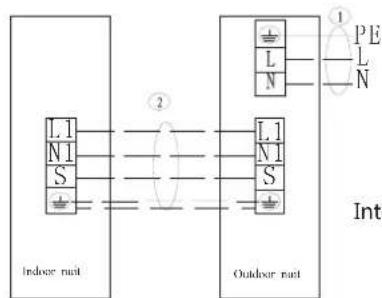
POWER SUPPLY 220-240V/50Hz
Interconnection cords are shielded wire
Applicable for (220-240V/50Hz) single phase model
POWER SUPPLY 380-415V3N/50Hz
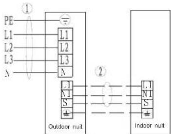
Interconnection cords are shielded wire
Applicable for (380V/50Hz) ≥ three phase model

Notice
- To avoid abnormal operation of the unit caused by electromagnetic interference, attention should be paid to avoid the interference signal source when connecting cables.
- The wiring diagram is for reference only, when wiring, physical objects will prevail!
5.6 Unit wiring
Note: The cross-sectional area of the conductor selected by user must not be less than the specifications listed in the table. If the user's power cord is too far away from the unit, make a corresponding increase in the cross-sectional area of the line group to ensure the normal power supply.
Power supply line specifications
| Model\Name | Outdoor power supply line (quantity, diameter)H05RN-F | Indoor power supply line(quantity, diameter)H05VV-F | Indoor /outdoor connection line(quantity, diameter) | Power supply method |
| Single phase 18K model | 3 × 1.5mm^2 | / | 4 × 1.0mm^2 | Outdoor Power Supply |
| Single phase 24K model | 3 × 2.5mm^2 | / | 4 × 1.0mm^2 | Outdoor Power Supply |
| Single phase ≥slant 36K model | 3 × 4mm^2 | / | 4 × 1.5mm^2 | Outdoor Power Supply |
| 3- phase ≥slant 36K model | 3 × 2.5mm^2 | / | 4 × 1.5mm^2 | Outdoor Power Supply |
5.7 Fault code
Table 1: Indoor unit (digital display)
When unit is standby after first time power on, running light flash slowly, after operation, all the lights off when the unit is off or standby.
When unit is running, running light flashes, digital tube shows setting temperature in cooling and heating mode, digital tube shows indoor temperature in fan only mode; defrost light turns on when defrosting, timer light turns on when in timer mode.
| Display Error description Display Error description | |||
| E0 Phase protection F0 (reserve) | |||
| E1 | Communication error between outdoor unit and indoor unit | F1 (reserve) | |
| E2 Indoor room temperature (T1) sensor error F2 (reserve) | |||
| E3 Indoor coil middle temperature (T2) sensor error F3 | Outdoor unit current error cannot recoverDisplay P3 error for 3 times within 60 minutes | ||
| E4 | Indoor coil outlet temperature (T2B) sensor error | F4 | Outdoor temperature (T4) sensor error |
| E5 | Outdoor unit error | F5 (reserve) | |
| E6 | Zero speed protection | F6 | Outdoor unit condenser outlet (T3) sensor error |
| E7 | EERPOM error | F7 | Secondary side current protection |
| E8 | Indoor fan motor speed lose protection | F8 | Heat T2 temp. protection |
| E9 | Wired controller communication error | F9 | Outdoor unit voltage error |
| EE | Water level alarm error | ||
| EF | EF(reserve) | ||
Table 1: Indoor unit (digital display)
| Display Error description Display Error description | |||
| P0 (reserve) H0 | Communication error between outdoor unit main board and driver board | ||
| P1 (reserve) H1 (reserve) | |||
| P2 (reserve) H2 (reserve) | |||
| P3 Primary/secondary overcurrent protection H3 (reserve) | |||
| P4 | Exhaust temperature over-high protection | H4 | 3 times of P6 error within 30 minutes |
| P5 | Outdoor unit condenser outlet (T3) temperature over-high protection | H5 | 3 times of P2 error within 30 minutes |
| P6 | Compressor driver error or IPM protection | H6 | 3 times of P4 error within 100 minutes |
| P7 (reserve) H7 (reserve) | |||
| P8 (reserve) H8 (reserve) | |||
| P9 | Outdoor unit DC fan motor error | H9 | 2 times of P9 error within 10 minutes |
Table 2: Indoor unit (LED display)
| Error description | Display content |
| Indoor unit waiting for address assignment | LED timer and running flash together |
| (reserve) | LED timer, running, protection, defrost flash together |
| Communication error between outdoor unit and indoor unit | LED timer flash quickly |
| Fan motor stall protection | LED timer flash slowly |
| Indoor unit temperature sensor error | LED run flash |
| Water level alarm | LED protection flash |
| (reserve) | LED defrost flash |
| Outdoor unit error | LED protection flash slowly |
| EEPROM error | LED defrost flash slowly |
Quickly flash is 2.5Hz, slowly flash is 0.5Hz.
| Error type | Running | Defrost | Timer | Protection |
| Outdoor unit condenser outlet (T3) sensor error | OFF | OFF | ON | ON |
| Outdoor temperature (T4) sensor error | OFF | OFF | Flashing | ON |
| AC overvoltage/undervoltage protection | OFF | Flashing | OFF | ON |
| P6 protection | OFF | Flashing | ON | ON |
| Compressor protection | OFF | ON | OFF | ON |
| Compressor top temperature (T5) over-high protection | OFF | ON | ON | ON |
| Outdoor DC fan motor error | OFF | ON | Flashing | ON |
| Over current protection | ON | ON | OFF | ON |
Table 3: Wired controller
| Spot check NO. | Content | Spot check NO. | Content |
| 1 Indoor | unit capacity 11 Opening of EXV | ||
| 2 | Indoor unit capacity demand | 12 | Running frequency of compressor |
| 3 | Indoor demand after T4 amendment | 13 Primary voltage/4 | |
| 4 | Indoor demand after T2 amendment | ||
| 5 | Indoor room temperature (T1) temperature | ||
| 6 | Indoor coil middle temperature (T2) temperature | ||
| 7 | Indoor coil outlet temperature (T2B) temperature | ||
| 8 | Outdoor unit condenser outlet (T3) temperature | ||
| 9 | Outdoor temperature (T4) temperature | ||
| 10 | Compressor top temperature (T5) temperature (maximum 99°C) | ||
| Display | Error description | Display | Error description |
| E0 | Phase protection | F0 | (reserve) |
| E1 | Communication error between outdoor unit and indoor unit | F1 | (reserve) |
| E2 | Indoor room temperature (T1) sensor error | F2 | (reserve) |
| E3 | Indoor coil middle temperature (T2) sensor error | F3 | Outdoor unit current error cannot recoverDisplay P3 error for 3 times within 60 minutes |
| E4 | Indoor coil outlet temperature (T2B) sensor error | F4 | Outdoor temperature (T4) sensor error |
| E5 | Outdoor unit error F5 | (reserve) | |
| E6 | Zero speed protection | F6 | Outdoor unit condenser outlet (T3) sensor error |
| E7 | EERPOM error | F7 | Secondary side current protection |
| E8 | Indoor fan motor speed lose protection | F8 | Heat T2 temp. protection |
| E9 | Wired controller communication error | F9 | Outdoor unit voltage error |
| EE | Water level alarm error | ||
| EF | EF(reserve) |
Table 3: Wired controller
| Display Error description Display Error description | |||
| P0 (reserve) H0 | Communication error between outdoor unit main board and driver board | ||
| P1 (reserve) H1 (reserve) | |||
| P2 (reserve) H2 (reserve) | |||
| P3 Primary/secondary overcurrent protection H3 (reserve) | |||
| P4 | Exhaust temperature over-high protection | H4 | 3 times of P6 error within 30 minutes |
| P5 | Outdoor unit condenser outlet (T3) temperature over-high protection | H5 | 3 times of P2 error within 30 minutes |
| P6 | Compressor driver error or IPM protection | H6 | 3 times of P4 error within 100 minutes |
| P7 (reserve) H7 (reserve) | |||
| P8 (reserve) H8 (reserve) | |||
| P9 | Outdoor unit DC fan motor error | H9 | 2 times of P9 error within 10 minutes |
| 1 Name Quantity Remarks | ||
| 2 Indoor unit 1 | ||
| 3 Installation and operation manual | 1 | Include User Service Guidance and Product Certification |
| 4 Remote controller 1 | ||
| 5 Batteries 2 | ||
| 6 Outdoor unit 1 | ||
| 7 Heat insulating sleeve | 2 | |
| 8 Drain pipe (for floor installation style) | 1 | |
Packing
Inspection
natural_image
Diagram of a battery pack with two cylindrical cells and four terminals (no text or symbols)natural_image
Technical line drawing of a battery pack assembly (no text or symbols)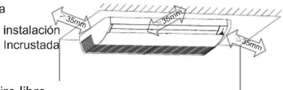
natural_image
Pure mechanical assembly diagram showing two vertical supports connected to a horizontal beam with mounting holes (no text or symbols)natural_image
Pure technical line drawing of two cylindrical components with no text or symbolsnatural_image
Pure technical diagrams showing three different mechanical or structural configurations without any text, numbers, or symbols.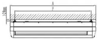
natural_image
Technical line drawing of a mechanical device casing with internal compartments and mounting brackets (no text or symbols)natural_image
Illustration of hands using a tool to lift a cylindrical object, showing motion arrows (no text or symbols)| Diámetro exterior de la tubería de cobre (mm) | Tightening torque (N·cm) | Reinforce tightening torque(N·cm) |
| Φ6.3 or Φ6 | 1570(160kgf·cm) | 1960(200kgf·cm) |
| Φ9.52 or Φ9 | 2940(300kgf·cm) | 3430(350kgf·cm) |
| Φ12.7 or Φ12 | 4900(500kgf·cm) | 5390(550kgf·cm) |
| Φ16 | 7360(750kgf·cm) | 7850(800kgf·cm) |
| Φ19 | 9720(900kgf·cm) | 11860(1210kgf·cm) |
natural_image
Pure electrical circuit lines without any symbolsnatural_image
Technical line drawing of a dual-panel air conditioning unit with circular vented structure (no text or symbols)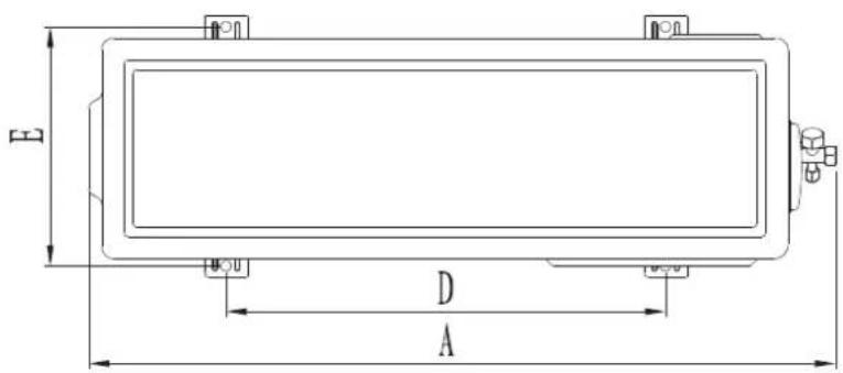
Unidad: mm
natural_image
Technical line drawing of a rectangular industrial air conditioning unit with circular fan pattern and labeled dimensions A and D (no text or symbols beyond labels)Unidad: mm
natural_image
Technical line drawing of a large air conditioning unit with circular fan pattern and control panel (no text or symbols)Figura 12.1
Unidad: mm
natural_image
Technical line drawing of a vertical cabinet or enclosure with internal compartments and mounting feet (no text or symbols)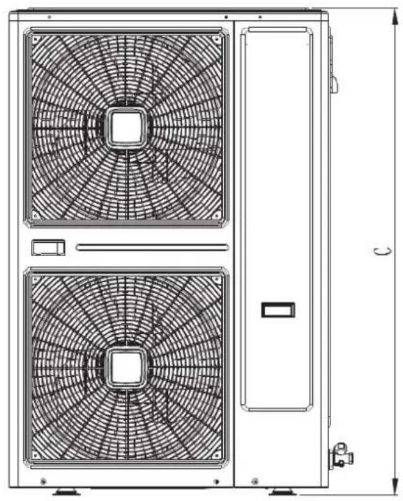
natural_image
Technical line drawing of a dual-panel HVAC unit with fan patterns and ventilation slots (no text or symbols)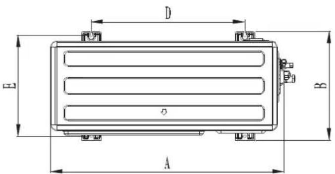
Figura 12.2
Unidad: mm

- Instruction Manual
- INFINITON
- Content
- Notice
- NOTE
- Introduction for remote controller and light board (standard)
- Replacement of the battery of remote controller
- Note:
- WARNING
- ◆Select the installation location for the indoor unit
- ◆ Select the installation location for the outdoor unit
- ◆Electrics installation requirements
- ■ For the first installation
- ■ During installation construction
- 1 Indoor unit installation
- ◆Piping and banding
- ◆ Install the drainpipe
- Installation of outdoor unit
- Lifting of equipment
- Connection and installation of indoor, outdoor unit refrigerant pipe
- Pipeline inspection
- 2.Pipe connections
- Notes:
- Accessory pipe in the pipeline
- The use of oil return elbow
- Connection of wires and terminal blocks
- Connection of the power cord
- Line controller 9 : Cable connection
- Installation of connecting cables for indoor unit and outdoor unit
- Unit wiring diagram
- Unit wiring
- Fault code
Brand : Infiniton
Model : CCFL-4530
Category : Air conditioner