CSTT-4550 - Air-conditioner Infiniton - Free user manual and instructions
Find the device manual for free CSTT-4550 Infiniton in PDF.

User questions about CSTT-4550 Infiniton
0 question about this device. Answer the ones you know or ask your own.
Ask a new question about this device
Download the instructions for your Air-conditioner in PDF format for free! Find your manual CSTT-4550 - Infiniton and take your electronic device back in hand. On this page are published all the documents necessary for the use of your device. CSTT-4550 by Infiniton.
USER MANUAL CSTT-4550 Infiniton
DC Inverter ceiling-mounted cassette type air conditioner
Instruction Manual
CSTT-4550
CSTT-6050
CSTT-9400
- Original instructions
- This appliance is intended to be used by expert or trained users in shops, in light industry and on farms, or for commercial use by lay persons.
- GWP: R410A: 2087.5 or GWP: R407C: 1773.9.
- This appliance is not intended for use by persons (including children) with reduced physical, sensory or mental capabilities, or lack of experience and knowledge, unless they have been given supervision or instruction concerning use of the appliance by a person responsible for their safety.
- Children should be supervised to ensure that they do not play with the appliance.
- The appliance shall be installed in accordance with national wiring regulations.
- This appliance can be used by children aged from 8 years and above and persons with reduced physical, sensory or mental capabilities or lack of experience and knowledge if they have been given supervision or instruction concerning use of the appliance in a safe way and understand the hazards involved.
- Children shall not play with the appliance.
- Cleaning and user maintenance shall not be made by children without supervision.
- Disconnect the appliance from its power source during service and when replacing parts.
- The appliance must be installed 2,3m above floor.
- Warning: before obtaining access to terminals, all supply circuits must be disconnected.
- If the supply cord is damaged, it must be replaced by the manufacturer, its service agent or a similarly qualified person in order to avoid a hazard.
- An all-pole disconnection switch having a contact separation of at least 3mm in all poles should be connected in fixed wiring.
- Disconnect the power supply before cleaning and maintenance.
- The appliance shall not be installed in the laundry.
- F-Gas label:
The equipment contains fluorinated greenhouse gas R32
Global Warming Potential(GWP):675

18.

text_image
CE
| Correct Disposal of this product | |
| This marking | indicates that this product should not be disposed with other household wastes throughout the EU. To prevent possible harm to the environment or human health from uncontrolled waste disposal, recycle responsibly to promote the sustainable reuse of material resources. I return your used device, please use the return and collection systems contact the retailer where the product was purchased. They can take to product for environmental safe recycling. |
Content
- Notice for User 1
2.Name of air conditioner components 4
3.Preparation before installation 8 - Installation of unit 1
- Test run 20
- Maintenance and service 21
- Symptom analysis and treatment 23
- Electric installation 26
Appendix: Unit Packing List
Safety Notice
Safety Notice provides the most important safety-related and unit operation key points. Be sure to operate accordingly. Meanings of symbols in documents:

Warning
It may lead to death, serious injury or major accidents due to mistaken operation.

Notice
It may lead to safety accident, machine damage or impair the unit operation effect due to improper operation.
Please carefully read the label on main machine; if any abnormal conditions detected such as abnormal noise, odor, smog, temperature rise, electric leak or fire, please immediately cut off the power supply and contact local customer service center or dealer of our company rather than automatic repairing. Immediately contact local fire control and first aid department if necessary.
- The appliance shall operate in a room without any continuously operating ignition sources;
- Have to refer to the safety instruction before installing the appliance.

Warning
- The unit must not be mounted by own. it must be mounted by the dealer or professional installation company authorized by our company; otherwise it may lead to safety accident and impair the operation effect.
- Unless operation instructed by professional staff, the non-professional staff must not remove the unit at will; otherwise it may lead to accident or damage the unit.
- Do not operate or store inflammable or explosive articles around or below the unit; otherwise it may lead to fire hazard.
- The main power supply switch of unit shall be placed in the location unavailable by the child so as not to cause hazard.
- Do not sprinkle the water or other fluid on the unit; otherwise it may lead to electric leak risk.
- Do not touch this unit with wet hand; otherwise it may lead to electric shock.
- In stormy weather, please cut off the unit main power supply switch; otherwise it may lead to lightning risk and therefore damage the unit due to lightning.
- Before long time out-of-work of unit, please cut off the main supply switch so as to avoid accident.
- The unit shall use independent power supply switch and special power circuit to avoid common circuit with other electric appliances; use the power supply wire with specified section area to supply for the unit and equip with the circuit breaker of related specifications (with electric leak protection function).
- The unit must be mounted with the grounding wire with specified section area and reliably mounted; do not connect the grounding wire with the earth wire of gas pipelines, water pipeline, arrester conductor or phone so as not to cause accident electric shock.
- Do not forcibly cut off the power supply during normal operation of unit so as not to cause accident.

Notice
- Do not extend the hand or foreign matters into the unit air outlet; otherwise the fan running at high speed may put your safety in hazard.
- Avoid moisture of unit electric control system; otherwise it may lead to short circuit or damage the machine.
- After cleaning the screen, install as origin state as quick as possible; do not operate the unit without screen; otherwise it may affect the operation effect.
- Please properly adjust the temperature in the room, especially when there is the elder, child or patient in the room.
- The lightning and other electromagnetic radiation sources may influence the unit; if so confirmed, please cut off the power supply and then power on after eliminated the influence.
- Do not use sundries to block or cover the air inlet and outlet of unit.
General precautions
- The outdoor unit must be mounted in the field with sunshade and rainproof facilities; otherwise our company will not be liable to the problem due to improper field.
- The operation parameters and protection device settings of unit have been set when the machine leaves the factory; the user must not change the settings at will, and not short circuit the line of unit protection unit; otherwise it may lead to unit damage due to improper protection.
- During operation of unit, any one except the professional staff must not touch any electric appliance and button; otherwise it may lead to serious accident.
- In case of failure of unit, the user shall timely report to the service center of our company for consultation and repair rather than repairing by himself; the repairing of unit by non-professional staff may lead to personal injury or unit damage.
- When cleaning the unit, do not use benzene, diluent or chemical cloth to wipe the operation panel, otherwise it may lead to fading or failure of button; do not directly spray the unit with water or cleaning agent; wipe with the cloth dipped with water or neutral cleaning agent if necessary.
- To extend the air conditioner service life, do not frequently start the compressor (no more than 5 times in 1 hour).
- The refrigerant used by the unit shall be non-inflammable and non-poisonous, but it will cause ill if inhaled too much; if any leak detected, immediately open the room window for ventilation so as to avoid asphyxia.
- In case of leak of refrigerant, the stress meter shall stop the operation of unit, and contact the maintenance staff timely; in case of open fire on site, the refrigerant may discompose into harmful gas due to contact open fire.
- Please carry out periodical maintenance of unit according to requirements in instruction to ensure normal hoperation conditions of unit.
Other Safety Notice
- The fuse of specified capacity must be used and no iron wire or copper wire must not be used.
- The unit operation environment shall be far from fire hazard location. In case of fire due to short circuit, immediately turn off the power supply master switch and extinguish the fire with dry powder fire extinguisher.
- It is necessary to cut off the power supply before maintenance of unit.
- Do not touch the exhaust side pipe fittings to avoid scalding since the temperature may be more than 100Centigrade.
- The sharp edge and fin surfaces are harmful, which must not be touched.
- Do not move the unit at will if no instruction of professional staff so as to accident and device damage.
- Do not touch the rotating fan blade with water or other articles so as to avoid personal injury and device damage.
- Do not place any article on unit to avoid risk due to article drop-off.
- Reusable mechanical connectors and flared joints are not allowed indoors.
Indoor unit

text_image
Air supply port of short pipeline 1. It can be used only in case with special demand 2. The connection of short pipe can be placed at one side. Air supply port Air conditioner filter (in air return grating) Air return grating Water drainage device (Built-in) Drain the water to be removed from the inside during refrigeration operation Air guide bar (in air supply port) Refrigerant pipe Connection wire Grounding The details of installation of water drain pipe refer to page 16Indication lamp board
flowchart
graph TD
    A["Defrosting pre-heating light"] --> B["Operation"]
    C["Operation indication light"] --> B
    D["Remote control signal receiving window"] --> B
    B --> E["Operation"]
    B --> F["Defrosting Timing Protection"]
    G["Timing setting indication lamp"] --> E
    H["The protection lamp illuminates when the water is filled"] --> E
    I["Emergency key"] --> E
LED display light board
flowchart
graph LR
    A["Operation Indication light"] --> B["Operation"]
    C["Emergency key"] --> D["Defrosting pre-heating light"]
    B --> E["Defrosting"]
    D --> E
    E --> F["heating"]
    F --> G["Timing"]
    G --> H["Alarm"]
    H --> I["Digital display pipe"]
    I --> J["n case of failure of unit, the protection amp illuminates;"]
    H --> K["Remote control signal receiving window"]
    L["Timing setting light"] --> M["End"]
Digital pipe display light board
Note: When using digital code display board, the 3th position of dialing SW2 on the electronic controller shall be turned to ON position (as shown in right figure); in case of failure of remote controller, press emergency key for emergency operation.
Outdoor machine (the drawing below is only for reference)

text_image
Air inlet Air outlet Air outlet Air inlet Air outlet Air outletRemote controller

flowchart
graph TD
A["Temperature addition<br>Increase the setting temperature."] --> B["FAN-"]
C["Temperature reduction<br>Decrease the setting temperature."] --> B
D[""ON/OFF"<br>Open or close the air-conditioner."] --> B
E["Fan speed<br>Reduce fan speed in one gear.<br>Minimum wind speed will switch to the automatic wind, and switch to the highest wind when pressing again."] --> B
F["Timer<br>Setting timing ON/OFF."] --> B
G["Clock<br>Modify the current time of the remote controller."] --> H["CLOCK"]
I["Lock<br>Lock the remote controller bottoms."] --> H
B --> J["FAN+"]
K["TIMER"] --> L["CLOCK"]
M["TURBO"] --> N["LIGHT"]
O["ECON"] --> P["SLEEP"]
Q["SLEEP"] --> R["LIGHT"]
S["MODE"] --> T["Select modes, including automatic, cooling, dehumidification, fan and heating mode."]
U["Fan speed"] --> V["Increase fan speed in one gear,<br>Highest wind speed will switch to the automatic wind, and switch to the minimum wind when pressing again."]
W["Turbo"] --> X["Enter the turbo function. Decide whether to have this function according to the actual model."]
Y["ECON"] --> Z["Automatically setting 26 °C in cooling or heating mode."]
AA["Sleep"] --> AB["Enter the sleep function. Decide whether to have this function according to the actual model."]
AC["Light"] --> AD["Forced closing or lighting of display panel. Decide whether to have this function according to the actual model."]
AE["Up and down swinging<br>Open the external pendulum wind."]
AF["Left and right swinging<br>Open the internal pendulum wind."]
Function description:
ON/OFF key: When pressing the key, the remote controller circulates in sequence of "ON→OFF→ON".
During OFF→ON for first power on, the default setting of working status (temperature setting 25°C, automatic mode, automatic wind speed, automatic swinging, automatic throttle, without light, without force, without purification, without sleep, without timing, without lock key). During OFF→ON for non-first power-on, the working status is that before power off. The lamp, purification, cancel, forced and timing functions will be canceled after power off.
Mode key: When pressing the mode key, the remote controller with circulate in sequence of "Automatic → Cooling → Dehumidification → Heating → Ventilation → Automatic".
Minus key: When pressing this key in dehumidification mode and automatic mode, the temperature will not change. In other modes, press this key once and the temperature setting will decrease by 1 in the sequence of "32°C→31°C→⋯→17°C→16°C".
Plus key: When pressing this key in dehumidification mode and automatic mode, the temperature will not change. In other modes, press this key once and the temperature setting will increase by 1 in the sequence of "16°C→17°C→…→31°C→32°C".
Swinging key: Indendumidation mode, the winging will be fixed and unadjustable. when pressing the swinging key, the remote controller will circulate in the sequence of "Swinging wind fixed direction wind natural wind swinging wind".
Wind direction key: The wind direction is set as winging state in default during first time power on; press this key and it will circulate in sequence of "Swing → Stop → Swing".
Wind speed key: The wind speed is set at automatic wind speed in default during first time power on; in dehumidification mode, the speed wind is fixed as low speed and can not be adjusted; it will have no response when pressing the wind speed key. In other modes, press this key and it will circulate in sequence of "Automatic wind → High speed wind → Medium speed wind → Low speed wind → automatic wind".
Timing key: Set at non-timing state in default; press this key for timing setting in unit of 1 hour in the sequence of "1 H→2 H→⋯→24 H→cancellation →1 H...". In power off state, press timing setting key to set power on setting; press timing setting key to set the timing switch in power ON state. After setting of timing function, decrease every 1 hour till reached the setting time when it will power on or off, and cancel the timing display. If the timing is activated, the timing will not be canceled if pressed mode key. If the timing is activated, pressing of other key will send the setting time.
Forced key: The remote controller is set of non-forced state in default; in automatic, dehumidification and ventilation modes, the forced key does no function (no display and no code emitted for force). When pressing this key in other mode, the forced mode will circulate between ON and OFF. The wind speed does not display if the forced mode is activated; the forced mode will be deactivated after switching themode if it is activated; the forced mode will be canceled when setting the sleep operation.
Sleep switch: When pressing the sleep key, circulate in sequence of "sleep → cancel sleep → sleep"; if the sleep mode is activated, it will not be canceled after changed the modeWhen pressing the sleepkey to sleep, the wind speed will automatically switch to low speed, but the pressing of wind speed keycan adjust the wind speed (except dehumidification mode)
Lock key: It is set as non-lock state in default; when pressing this key, the remote controller circulates in sequence of "Lock→Cancel lock→Lock". If the lock key is activated, all keys of remote controller other than lock key does no function. (Note: when the lock key is activated, the keys on cabinet unit remote controller and air conditioner operation panel will automatically lock; when pressing the key again, the remote controller and air conditioner will automatically unlock. In discrete unit, only the remote controller is locked, the emergency button will not be locked, but the main plate response.)
Light key: The split unit only locks the remote controller, but does not lock the emergency lock; the main board will response. It is set as non-lamp state in default; when pressing this key, the remote controller circulates in sequence of "Lamp→Cancel lamp→Lamp". If the lamp key is activated, after pressed the mode key, the lamp key indication will not be canceled.
Purification key: Set as non-purification state in default; when pressing this key, the remote controller will circulate in sequence of "Purification → Cancel purification → Purification". If the purification is activated, the purification will not be canceled after pressing the mode key. When pressing this key in power-off mode of remote controller, it will circulate in sequence of "Purification → Cancel purification → Purification". When open the purification separately during off-fixing wind, door is unadjustable, wind speed is adjustable.
Notices for remote controller:
① Do not place the remote controller near the high temperature heat sources such as electric carpet or heating oven.
② Do not put the remote controller at the position directly exposed to the sunshine.
③ Be careful not to drop off from high position; otherwise it may be damaged.
④ There must have no barrier between signal receiver and remote controller of air conditioner which may affect the receiving and transmitting of signal.
⑤ Do not splash the liquid such as water onto the remote controller.
⑥ Do not place the weight onto the remote controller.

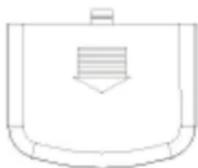
Note: In case of operation failure of remote controller, please replace with new battery and Remove the back cover repeat the operation; if the failure still exists, please run the air conditioner in emergency operation method, and contact the dealer or special maintenance points.
Replacement of remote controller battery
In case of following conditions, it indicates the battery is used up; take out the used battery and replace with new one.
① There is no air conditioner receiving sound after transmitted the signal.
② The display screen becomes obscure.
In case of above conditions, it indicates the battery is used up; take out the used battery and replace with new one.
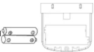
natural_image
Technical line drawing of a mechanical component with two cylindrical parts and a rounded rectangular housing (no text or symbols)A. Remove rear cover and take out the used battery.
B. Replace the battery; notice the "+" and "-" electrode marks of battery.
C. Close the rear cover.

Note:
- The new and used batteries must not be mixed.
- Please take out the battery if the remote controller is not used for long time.
Notice aligning the electrodes "+" and "-
Notice: The installation of unit must be done by professional staff; the improper installation may lead to water leak, electric shock or fire hazard.
Field selection
1. Indoor unit
1) It shall be installed at the place whether the air blown out can quickly spread the entire room and with certain maintenance space.
2) The air inlet and outlet of indoor unit will not be obstructed and affected by heat and vapor generated hereby.
3) Avoid installing at the place with large amount of fumes and vapors.
4) Avoid installing at the place with may generate, flow, stagnate or leak the inflammable gas.
5) Avoid installing near the devices which may generate high frequency, such as high frequency electric welder.
6) Avoid installing the air exhaust near the fire alarm.
7) Avoid installing at the place where frequently use the acid solution.
2. Outdoor unit
1) Install at the place where can not be directly exposed to the sunshine (if inevitable, please mount the sunshade facility to avoid direct exposure to the sunshine).
2) The noise and air flow generated by the unit will not affect the neighbor.
3) Convenient connection of indoor and outdoor unit and for ease of connection of power supply.
4) Do not install at the place where the inflammable gas may generate, flow, stagnate and leak.
5) During heating, the condensation drained out of outdoor unit chassis will not affect the neighbors or passer-by.
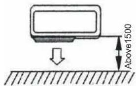
Installation requirements and maintenance space (outdoor unit)
1. Single unit installation (unit: mm)

text_image
Above 300 Above 500When there is barrier at upward side, if possible to keep the space shown in the figure, it does not matter even if there is barrier at back.

text_image
Above 300 Above 300 Above 300When the front side (outlet for exhaust) is open, if it can keep the space shown in the figure, it does not matter even if there are barriers at three sides. (Open above)
text_image
Above1500If there is barrier at the front side, the back, both sides and upward side shall be kept open.
text_image
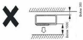
X Below 300 Below 1500When there are barriers at front side and both sides, do not use the dimensions shown in the figure. Please refer to the right figure
When there are barriers at front side and back side, at the location with barrier and poor air ventilation, to avoid short circuit of outdoor unit inlet and outlet, the heights and widths of barriers shall be within following range. (If its front side and back side can meet the condition, it will be no special limit for both sides.)
A. Barrier width is 1.5 times less than outdoor units
B. Barrier width is 1.0 times less than outdoor units
text_image
Above 300 Above 1500

When there are barriers around, even if the upward side is open, it can not installed.
text_image
Above 300 Above 500 As shown in the figure, ensure the maintenance space at front of unit Above 500 Maintenance space- Multi unit installation (unit: mm)
A. Parallel setting
text_image
Above 300 Above 500 Below 10 pcs Above 1500B. Multi-row arrangement

text_image
Above 5000C. Blowing arrangement
text_image
Above 500 Above 50003. Mounting at roof or other windy position
When the outdoor unit is to be mounted on the roof or place around which there is no building, it is necessary to avoid the strong force directly blowing into the air outlet of outdoor unit. To avoid impairing the heating or cooling effect and failure due of outdoor unit heat exchanger due to inadequate air flow.
A. When there is wall nearby, please locate the air exhaust facing the wall and keep about 500mm distance from the wall.
B. When the air exhaust is affected by strong wind or wind direction, it is necessary to change the air intake unit position to make the exhaust port perpendicular to the wind direction.
Install the indoor unit
1. Installation position
If the humidity and temperature on ceiling separately exceed 30^ C and RH80%, please affix the thermal insulation materials on machine. Please use the glass wool or foaming polyethylene with the thickness of more than 10mm. (If more than 10mm, please collect them at the position of inlet of ceiling.)
1) This indoor unit can be mounted on the ceiling of 2.5-3.5m high; but, when the ceiling height is higher than 2.7m, the tape must be sued for site setting.
2) Install and use the hoisting bolt; check whether the installation position can support the unit weight. If not security, please fasten before installation of unit. The hole distance is marked on installation paper model; refer to the mounting paper model and find the points to be reinforced.
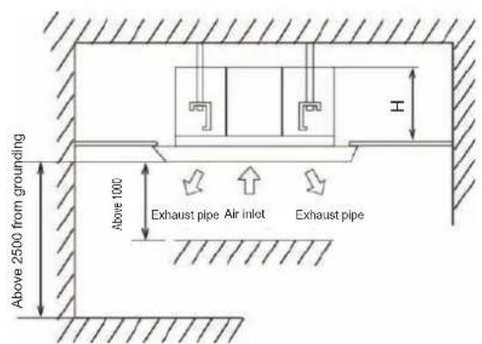
3) There must have no barrier in 1000mm from the air outlet.
Space required for installation
Unit: (mm)
text_image
Above 2500 from grounding Above 1000 Exhaust pipe Air inlet Exhaust pipe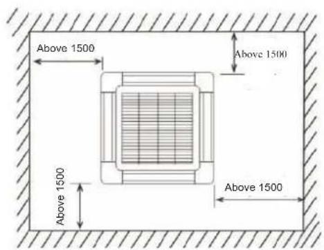
text_image
Above 1500 Above 1500 Above 1500 Above 1500| Model | Machine body height (H) |
| 18K | 267 |
| 24K | 230 |
| 36K 48K 55K | 285 |
Note: The actual dimensions refer to the actual product.
2. Preparation before installation
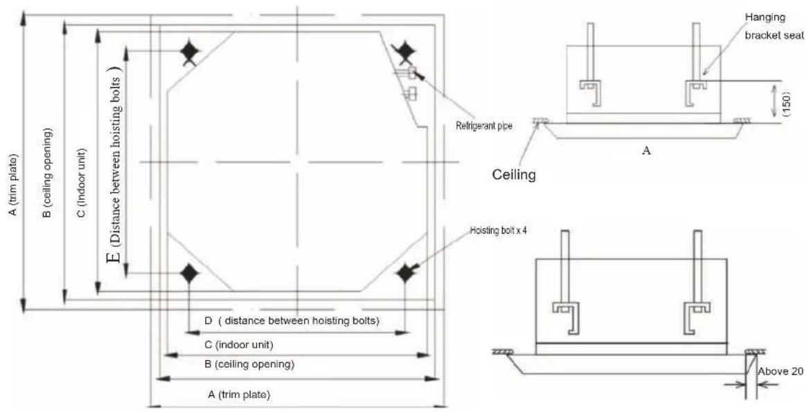
1) Position relationship among ceiling opening, unit and hoisting bolt
text_image
A (trim plate) B (ceiling opening) C (indoor unit) D (distance between hoisting bolts) E (Distance between hoisting bolts) A (trim plate) D (distance between hoisting bolts) C (indoor unit) B (ceiling opening) A (trim plate) Hanging bracket seat Refrigerant pipe Ceiling Hoisting bolt x 4 (150) Above 20Unit: (mm)
| Model | Size | ||||
| A | B | C | D | E | |
| 24K 36K 48K 55K | 950 | 890 | 840 680 | 780 | |
| 18K | 650 | 610 | 565 528 | 528 | |
Description:
- The overlapping section of ceiling and trimming plate shall be kept as more than 2.0mm.
- If necessary, open the opening on the ceiling required for installation. (In case the ceiling is mounted)
a. The dimensions of ceiling opening please refer to installation drawing.
b. Firstly complete all pipelines connecting with indoor unit (refrigerant pipe and drain pipe) and electric wires (connection pipes of indoor and outdoor units) before installation for ease of connection with the indoor unit after installation.
c. Reinforce the ceiling from the ceiling opening to keep the ceiling level and avoid vibration of ceiling.
2) Installation of hoisting bolt
- To support the weight of units, use anchor bolt for existing ceiling; use embedded bolt or other parts provided on site for the new ceiling.
- Before continuing the installation, adjust the clearance from the ceiling.
3. Installation
A. When there is no installation position on the ceiling
①Attach the hanging bracket seat to the hoisting bolt; be sure to use bolt and nut separately at upper and lower head of the hanging bracket seat to firmly fix the hanging bracket seat; use locating plate 7 to avoid the washer coming-off.
② The dimensions of ceiling opening please refer to installation drawing 5. The details refers to the building agent or carpenter. The indoor unit center is marked on the attached installation drawings shown in the figure below, the screws 6 (3 pcs) mount the installation label on the unit; fix the angle of drain channel at pipeline outlet with screw.
③ Adjust the unit to correct installation positions.
④ Check whether the unit is level. The indoor unit is equipped with embedded drain and float switch. Check whether the four angles of unit are level with level or polyethylene pipe filled with water one by one (if the condensation water flow of unit inclines towards reverse direction, the float switch may be unable to work, which may lead to drip)
⑤ Remove the washer fixing plate 7 to avoid drop-off of waterproof washer and tighten the upper nut.
⑥ Remove the installation label.
B. When there is installation position on the ceiling
① Be temporarily install the indoor unit Attach the hanging bracket on the hoisting bolts.
bolt and nut separately at upper and lower head of the hanging bracket seat to firmly fix the hanging bracket seat; use locating plate 7 to avoid the washer coming-off.
② Adjust the height and position of unit.

text_image
Left Nut (provided on site) Washer 3 (attachment) Right Hanging bracket seat Tighten (double nut) [ ] Firmly fix the hanging bracket seat During installation of hoisting bolt, step at the leftmost or rightmost to ensure firm installation of machine. Level polyethylene pipe Center of ceiling opening Insert Washer fixing plate 7 (attachment) [Firmly fix the washer] The angle of pipeline outlet is that fixed at the drain groove with screw. Installation label 5 Screw 6 (attachment) [Fix the installation label]4. Preparation of trim panel
B. Install the trim panel
① Do not face the panel downward; do not lean against the wall or onto the protruding object.
② Do not knock or extrude the swinging baffle. (Otherwise it may lead to failure)
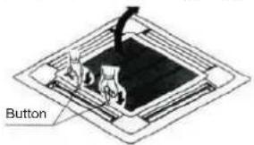
Take down the air return grating from the trim panel
- First pull down the air return grating and then pull up the other end of button. (See the figure below)
- Pull up the grating for about 45 degrees and take down the air return grating on trim panel. (See the figure below)
Take down the seal cover on angle (pull out the seal cover, as shown in figure below)
text_image
Button
natural_image
Isometric diagram of a structural frame with diagonal reinforcement and internal components (no text or symbols)
B. Install the trim panel on indoor unit
① As shown in the figure below, align the position of swinging baffle motor on trim panel with the pipe opening position of indoor unit for ease of installation of trim panel onto the indoor unit.
② Install the trim panel
a. Temporarily install the trim panel onto the indoor unit; during installation, hang the buckle on reverse position of swinging baffle motor of trim panel onto the hook of indoor unit (notice not winding the swinging motor conductor into sealing materials)
b. Temporarily hang the other 2 buckles onto the hook of indoor unit. (Notice not winding the swinging motor conductor into sealing materials.)
c. Screw 4 hexagon bolts under the hook in for about 5mm. (The panel will lift)
d. Tighten the screw till the thickness of sealing materials between trim panel and indoor unit decreases to 5-8mm.
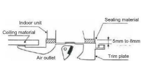
text_image
Indoor unit Ceiling material Sealing material 5mm to 8mm Air outlet Trim plate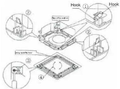
text_image
Hook ① Hook ② Pin 400 mm x 200 mm ③ wing up bolt hole ④The improper tightening of screw may lead to the failure as shown in the figure below. Re-tighten the screw to the specification requirements.
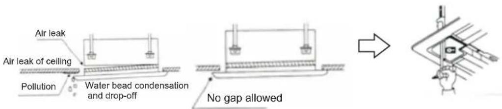
After tightening the screw, if there is still gap between ceiling and trim panel, please re-adjust the height of indoor unit.
Place the indoor unit at level state; it is possible to adjust the indoor unit height through the corner core on trim panel when the water drain pipe does not discharge the water.
text_image
Air leak Air leak of ceiling Pollution Water bead condensation and drop-off No gap allowedC. Hoisting height of indoor unit
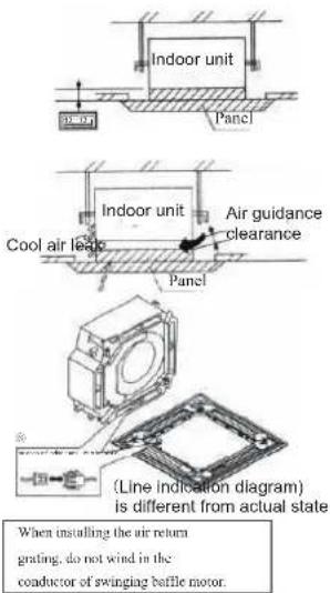
Please adjust the hoisting height of indoor unit to make the dimensions of indoor unit under the ceiling as shown in right figure.
① When there is gap between indoor unit and panel, the condensation may occur.
② Line of trim panel (see right figure)
a. Connect the joint of swinging baffle motor conductor (on the trim panel).
b. If not connecting the joint, the swinging baffle will not action. Properly connect the joint.
c. Confirm the conductor of swinging baffle motor is not clamped between indoor unit and trim panel.
- Installation of air return grating and cap
A. Install the air return grating
B. Install in reverse sequences to "Preparation of trim panel". While

natural_image
Pure architectural or mechanical line drawing without any text, numbers, or symbolsInstall in reverse sequences to "Preparation of trim panel". While rotating the air return grating, it can be installed in 4 directions. If necessary to adjust the installation direction of air return grating or required by the user, the installation direction can be changed.
text_image
Indoor unit Panel Indoor unit Cool air leak Air guidance clearance Panel Line Indication Diagram is different from actual state When installing the air return grating, do not wind in the coductor of swinging baffle motor.C. Firstly hang the air inlet grating onto the panel and then separately connect the lead connectors of swinging motor and control box on panel to related connectors of body.
D. Re-install the air inlet grating in reverse sequence to those when removing the air inlet grating;
E. Re-install the mounting cover plate.
① Fix the mounting cover plate rope onto the lug (see the right figure);
② Gently press the mounting cover plate in the panel.

text_image
No gap allowed ① First loosen the upper nut ② Adjust the lower nut
text_image
Install the cover plate self-tapping screw When installing the cover plate, mount 4 slide fasteners into related slots.Install the outdoor fan
1. Installation notice:
A. Transport the machine parts in origin package state to installation location.
B. Since the outdoor unit weight deflects from center position, take care when lifting the machine parts with sling.
C. The inclination of outdoor unit during transportation must not exceed 45^ C (do not store in horizontal state).
2. Installation
A. When installing the outdoor unit, use bolt to fix the unit footing. (Anchor bolt will be prepared on site)
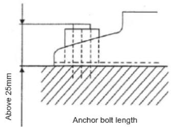
text_image
Above 25mm Anchor bolt lengthNote: Keep the maximum anchor bolt length as 25mm calculated from bottom installation foundation.
Install the refrigerant pipe and drain pipe
Note:
① If no special conditions, select the pipe fittings of our company.
② Due to special conditions, the thermal insulation sleeve of more than 9mm thick and with favorable thermal insulation performance to avoid condensation when otherwise procuring the refrigerant pipe.
③ When installing the drainage hose (accessory), additionally procure the cable tray connection exhaust pipe with inner diameter of 16 , and bind up with the thermal insulation sleeve of 9mm thick to avoid condensation.
1. Dimension of refrigerant pipe
| Model Refrigerant liquid pipe Refrigerant gas pipe | ||
| 18K series | External diameter 6.35 (1/4") | External diameter 12.7 (1/2") |
| 24K series | External diameter 9.52(3/8") | External diameter 15.88(5/8") |
| ≥slant 36K series | External diameter 9.52(3/8") | External diameter 15.88 (5/8") |
2. Length and height difference of ultra-long piping of air conditioning unit

flowchart
graph TD
    A["Indoor unit"] --> B["Outdoor"]
    B --> C["Arrow C"]
    style A fill:#f9f,stroke:#333
    style B fill:#ccf,stroke:#333
    style C fill:#cfc,stroke:#333
| Value\Rated refrigerating capacity | <6.5kW | 6.5~7.2kW | ≥10.5kW |
| A Pipeline length (one-way) | Maximum length 15m | Maximum length 20m | Maximum length 50m |
| B Height difference(one-way) | Maximum length 8m | Maximum length 10m | Maximum length 20m |
| C Pipeline bends quantity | Up to 10 | Up to 10 | Up to 15 |
Note: When the height is more than 5m, set the oil trapping bend and non-return bend according to relative positions of outdoor unit and indoor unit.
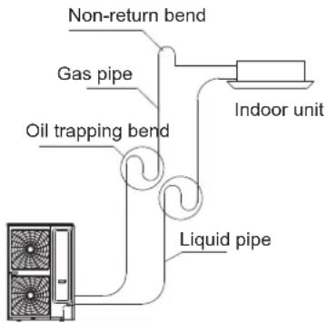
text_image
Non-return bend Gas pipe Oil trapping bend Indoor unit Liquid pipeOutdoor unit
When the installation position of indoor unit is higher than outdoor unit
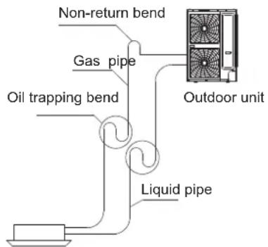
text_image
Non-return bend Gas pipe Oil trapping bend Liquid pipe Outdoor unitIndoor unit When the installation position of indoor unit is lower than outdoor unit
3. Piping sequence
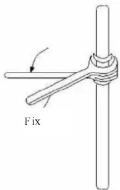
A. Keep the check valve or ball valve of outdoor unit closed (factory delivery specification) and separately remove the nuts, dustproof cap and piping screw plugs of indoor and outdoor pipelines.
① Quickly fulfill the bell mouth connection operation; if placed for long time, the dust, moisture and foreign matter may ingress and therefore lead to the failure.
② Before tightening the bell mouth, apply a thin layer of refrigeration oil on the sealing fitting surface of pipe
| Pipe diameter φ(mm) | Tightening torque (kgfm) |
| 6.35 1.4~1.7 | |
| 9.52 | 1.4~1.7 |
| 12.7 | 4.8~6.2 |
| 15.88 | 4.8~6.2 |
| 19.05 6.9~9.9 |
text_image
FixNotice:
Use two wrenches, one as common wrench and the other is torque wrench.
B. Conduct the bell mouth connection operations in sequence and connect all refrigerant pipeline.
After connection of pipe, it must be filled with nitrogen or refrigerant; check the air leak with leak detector or soap water.
C. Vacuumize the overhaul port of check valve or ball valve of outdoor unit and discharge the air.
(Operate by professional installation)
Notice:
①When the connection pipe length is more than 5m, it must be evacuated with vacuum pump; after evaporation, it shall be refilled according to requirements of "Adjustment of refrigerant usage amount".
②If the air conditioner is necessary to transfer to the other position, discharge the air with vacuum pump or refrigerant.
D. After completed above operation, it is necessary to fully open the check valve or ball valve of outdoor unit.
Pressure test, vacuumizing and leak test of connecting pipe and indoor unit pipeline:
After installed the connecting pipe and indoor unit, firstly charge the nitrogen into the connecting pipe and indoor unit pipe to 3.0Mpa and keep the pressure for 24h; at same time, check the leak with soap bubble at the connectors and welding positions; if no leak detected any more, discharge the nitrogen and vacuumize with vacuum pump (the vacuum degree shall be less than 30Pa), and then open the main machine valve for test run; if the refrigerant pipe length is more than 5m, refill the refrigerant and refer to following empirical formula:
R = (L10.012 kg/m) + (L20.024 kg/m) Where: L1-Total actual length of 6.4 liquid pipe (m).
L2-Total actual length of 9.5 liquid pipe (m). When refilling the refrigerant, use the needle valve on low pressure valve body of outdoor unit in refrigeration mode.
- Install the drainage pipeline
Please confirm there are enough space at unit installation position to mount the drainage pipeline, and ensure the drain pipe diameter is no less than that of connection pipe. (Polyethylene pipe, dimension: 25mm; outer diameter; 32mm)
A. The drain pipe should be short, and the slope of sagging should be equal to and more than 1%, to ensure drainage smoothness and avoid condensate lag
B. If impossible to ensure adequate slope for drainage hose, the drainage lift pipe shall be installed.
C. To avoid bending of drainage hose, it will keep 1 to 1.5m distance between hanging bracket.
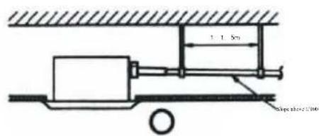
text_image
1.1.5m dipolarizer 2100
natural_image
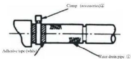
Pure mechanical diagram showing a lever and base assembly without any text, numbers, or symbolsD. Use the attached drainage pipe①and clamp ②
Insert the drainage hose into drainage socket till the white rubber belt. Tighten the clamp till the distance of screw head from hose is less than 4mm.
E. The condensation may lead to water leak, so it is necessary to fulfill thermal insulation construction for following two components.
-
Drainage pipe in room;
-
The drainage socket refers to the figure below; insulate the thermal for clamp and drainage pipe with attached large sealing pad⑩
text_image
Clamp (accessories)② Adhesive tape (white) Water drain pipe ①
text_image
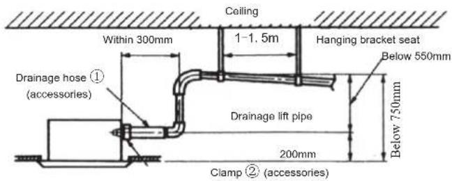
Large sealing pad (accessories) Clamp (accessories) Below 4mmNotice for the drainage lift pipe:
- The installation height of drainage lift pipe shall be less than 550mm.
- The exhaust lift pipe shall be perpendicular to the unit and be no more than 300mm from the unit.
text_image
Ceiling 1-1.5m Within 300mm Hanging bracket seat Below 550mm Drainage lift pipe 200mm Clamp ② (accessories) Drainage hose ① (accessories)Notice:
- Do not make the attached drainage hose subjected to excess force or bending and twisting. (It may lead to water leak)
- Please install according to following procedure if several drainage pipes converge.
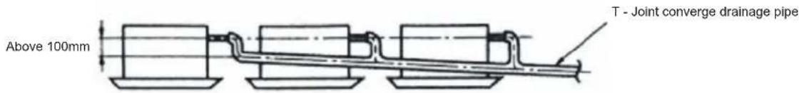
text_image
Above 100mm T - Joint converge drainage pipeThe specification of selected converge drainage pipe shall be suitable for operation capacity of unit. After completed the installation, slowly fill 2000cc water in the exhaust port or inspection hole and check whether the drainage is smooth; after installation of electric circuit, check the drainage conditions during refrigerant operation and the detailed instructions refer to "test run". Water injection method Access hole
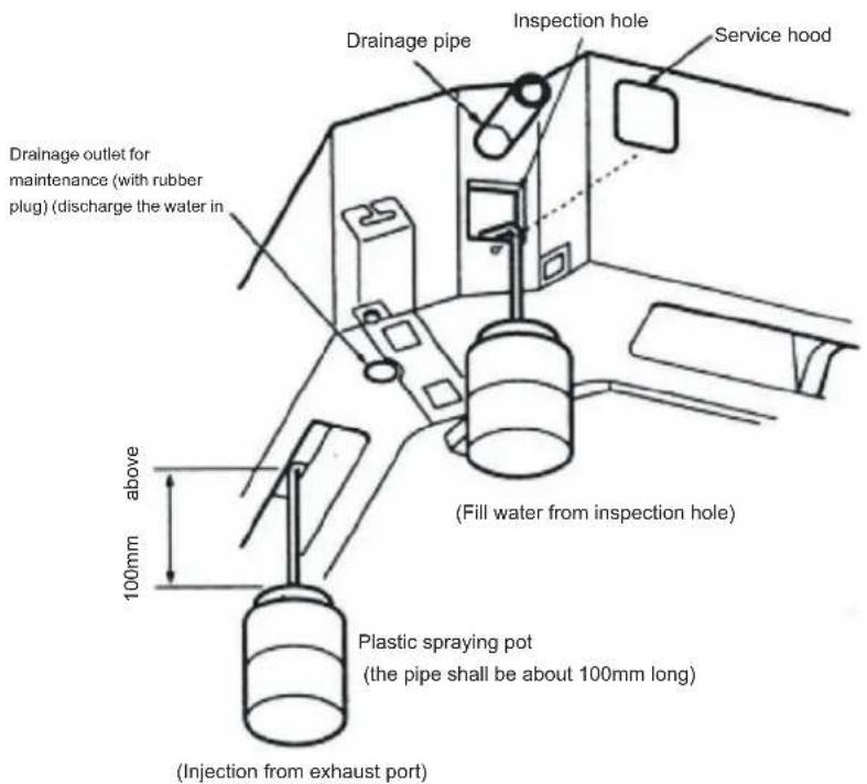
text_image
Drainage outlet for maintenance (with rubber plug) (discharge the water in 100mm above Drainage pipe Inspection hole Service hood (Fill water from inspection hole) Plastic spraying pot (the pipe shall be about 100mm long) (Injection from exhaust port)Confirmation before test run
After installation of indoor and outdoor units, piping and wiring, , please confirm there is no refrigerant leak, loose of power supply line and signal line, and no mistaken polarity.
Note: The compressor will not run in case of mistaken connection of power supply line.
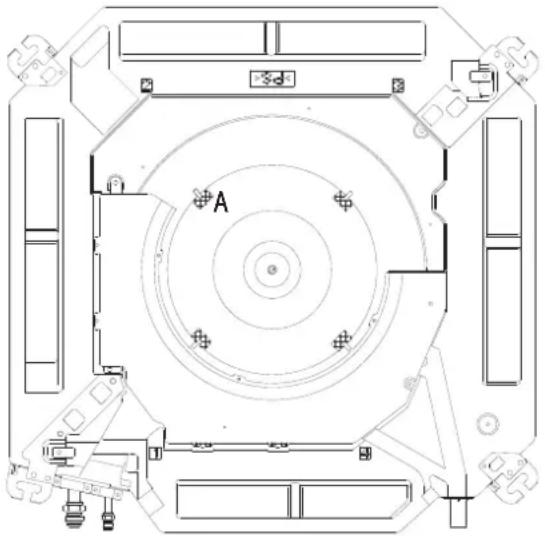
Note: Before test run, be sure to take out 4 air wheel damper blocks (A) and fixing tape!
natural_image
Top-down architectural floor plan of a circular mechanical or space facility with labeled components (no text or symbols beyond 'A')Test run
- Connect the main power supply of unit.
- Press the emergency operation switch (refrigeration or heating) and the air conditioner starts; the operation indication lamp will illuminate; check whether the operation of unit is normal; when pressed the emergency operation switch once again, it will stop the operation.
- Press the "ON/OFF" key of remote controller and confirm whether the indoor unit emits "Bee" sound; if heard, the remote controller functions and the emergency operation will be canceled; then operate the keys of remote controller to observe whether the operation modes of unit changes correspondingly.
A. Press "mode" key and select "air supply" mode; check whether there is air blowing out from the air conditioner.
B. Press "mode" key and select refrigeration mode; check whether there is cool air blowing out of the air conditioner.
C. Press "mode" key and select heating mode; check whether there is hot air flowing out of the air conditioner (without this mode for single cold type unit)
D. Press "wind speed" mode and select high speed mode; check whether there is strong wind blowing out of the air conditioner.
E. Press the "swing" mode, and observe if wind grate is normal swing.
Test the drainage device
- After installation of unit, it is necessary to check the drainage device.
- During test run, it is necessary to correctly drain out and ensure no leak of connector.
After installation and test run, the installation personnel shall introduce the operation method and safety notices to the user according to the operation instructions.
Frequently sweep the air filter screen
The blocked screen may reduce the air circulation volume and therefore the cooling/heating effect; the excess dirt of screen may lead to failure of air conditioner.
Please wash the screen once every two weeks.
If not used for long time, please wash the screen before used again.,
Cleaning procedures:
- Remove the filter screen:
- Sweep with dust collector or clean with water;
- After cleaning with water, place it in shady space for drying.
Notice: 1. Do not use more than 50°C hot water cleaning, so as not to fade or deformation.
-
Do not dry with the fire; otherwise the screen may catch fire.
-
Open the air return grating: press the buttons at two positions and slowly pull down. (Adopt same procedures when closing), as shown in the figure below:

- Take out the air return grating and open the grating for 45 degrees, and lift up as shown in the figure below:

- Remove the filter screen: support the hook on screen and pull out below it; take down the filter screen as shown in the figure below:

- After cleaning, install the filter screen and air return grating as shown in the figure below (operation in reverse

The room temperature is set at comfortable temperature
During refrigeration, the temperature shall be optimal when the difference of indoor and outdoor temperatures exceeds 5°C if the room temperature is too low, it will not do harm to the health and waste the electricity consumption; in refrigeration state, it can save about 10% electric energy for each °C increase of temperature setting.
Avoid the heat sources as possible
During refrigeration of air conditioner in room, firstly pull up the window curtain to block the direct sunlight; close the door window tight to avoid frequently opening.
Frequent ventilation
Regularly open the window for a time to enable the fresh air flowing into the room so as to make more comfort of air in room.
Start of operation season
- Check whether the outdoor unit is correctly installed, the grounding wire is correctly installed, the appearance of power supply line is complete.
- Check whether the air inlet and outlet of indoor unit and outdoor unit are smooth.
- Check whether the filter screen is properly installed.
End of operation season
- Start the air conditioner and set as air supply mode; after running for 3-4 hours, fully dry the inside of air conditioner;
- Turn off the air conditioner and cut off the special power supply of air conditioner;
- Completely clean the filter screen and indoor unit;
- Take out the battery in remote controller and properly place the remote controller;
- Cover the outdoor unit with protection hood to avoid ingress of dust.
Failure analysis
When the air conditioner can not normally operate, in case of any doubt, please read following contents before communicating the maintenance department so as to save valuable time and energy.
| Problems | Phenomenon | Reason | Handling method |
| No operation of air conditioning | Press the "ON/OFF" key of remote controller ON/OFF" key No "Bee" sound heard; OFF of operation indication lamp | Outage | Press "ON/OFF" key after recovery of power supply |
| Not connect the power supply | Connect the power supply | ||
| Fuse blown of power supply | Replace with new fuse | ||
| The electric leak switch is in OFF state | Turn on the electric leak switch | ||
| The remote controller operates out of operation range | Operate the remote controller in operation range | ||
| Use up of battery in remote controller (The indication on screen display becomes | Replace with new battery | ||
| The air conditioner can not immediately start up. | The remote controller indicates the unit is running. | Protection of compressor | Wait for automatic release of compressor protection or call the dealer for drop-in service |
| The air conditioner stops operation shortly after startup. | The air inlet or outlet of indoor or outdoor unit is blocked. | Remove the blockage | |
| The filter screen is blocked by dust or mud | Clean the filter screen | ||
| The air conditioner can deliver the air, but the air is not cool or not hot | The remote controller indicates the unit is running. | The temperature setting is too high during refrigeration. The temperature setting is too low during heating | Check the temperature setting on remote controller and re-set proper temperature |
| The filter screen is blocked by dust or mud | Clean the filter screen | ||
| The air inlet or outlet of indoor or outdoor unit is blocked. | Remove the blockage | ||
| Open the door and windows | Close the door and windows |
Once the unit stops operation due to outage, the unit will not restart even if recovery of power supply; to restart, press the "ON/OFF" key on remote controller.
The following cases are not of failure:
- Sometimes odor: air conditioner collects the odors of smoke, cosmetics, wall and furnitures in room and blows them out.
- Sometimes the "hiss" sound will be heard during or after operation, which is due to flowing out of refrigerant inside the air conditioner;
- During startup or stop of operation, the "Pi-Pa" sound will be heard sometimes, which is the sound from
Self diagnosis function
Our company provides considerate service for the customer and install various judgment systems to indicate following abnormalities.
Table 1: Indoor unit unit(digital display)
When unit is standby after first time power on, running light flash slowly, after operation, all the lights off when the unit is off or standby.
When unit is running, running light flashes, digital tube shows setting temperature in cooling and heating mode, digital tube shows indoor temperature in fan only mode; defrost light turns on when defrosting, timer light turns on when in timer mode.
| Display | Error description Display Error description | ||
| E0 Phase protection F0 (reserve) | |||
| E1 | Communication error between outdoor unit and indoor unit | F1 (reserve) | |
| E2 Indoor room temperature (T1) sensor error F2 (reserve) | |||
| E3 Indoor coil middle temperature (T2) sensor error | F3 | Outdoor unit current error cannot recoverDisplay P3 error for 3 times within 60 minutes | |
| E4 | Indoor coil outlet temperature (T2B) sensor error | F4 | Outdoor temperature (T4) sensor error |
| E5 | Outdoor unit error | F5 (reserve) | |
| E6 | Zero speed protection | F6 | Outdoor unit condenser outlet (T3) sensor error |
| E7 | EERPOM error | F7 | Secondary side current protection |
| E8 | Indoor fan motor speed lose protection | F8 | Heat T2 temp. protection |
| E9 | Wired controller communication error | F9 | Outdoor unit voltage error |
| EE | Water level alarm error | ||
| EF | EF(reserve) | ||
| Display | Error description | Display | Error description |
| P0 | (reserve) | H0 | Communication error between outdoor unit main board and driver board |
| P1 | (reserve) | H1 | (reserve) |
| P2 | (reserve) | H2 | (reserve) |
| P3 | Primary/secondary overcurrent protection | H3 | (reserve) |
| P4 | Exhaust temperature over-high protection | H4 | 3 times of P6 error within 30 minutes |
| P5 | Outdoor unit condenser outlet (T3) temperature over-high protection | H5 | 3 times of P2 error within 30 minutes |
| P6 | Compressor driver error or IPM protection | H6 | 3 times of P4 error within 100 minutes |
| P7 | (reserve) | H7 | (reserve) |
| P8 | (reserve) | H8 | (reserve) |
| P9 | Outdoor unit DC fan motor error | H9 | 2 times of P9 error within 10 minutes |
Table 2: Indoor unit (LED display)
| Error description Display content | |
| Indoor unit waiting for address assignment | LED timer and running flash together |
| (reserve) | LED timer, running, protection, defrost flash together |
| Communication error between outdoor unit and indoor unit | LED timer flash quickly |
| Fan motor stall protection | LED timer flash slowly |
| Indoor unit temperature sensor error | LED run flash |
| Water level alarm LED protection flash | |
| (reserve) LED defrost flash | |
| Outdoor unit error | LED protection flash slowly |
| EEPROM error | LED defrost flash slowly |
Quickly flash is 2.5Hz, slowly flash is 0.5Hz.
| Error type | Running | Defrost | Timer | Protection |
| Outdoor unit condenser outlet (T3) sensor error | OFF | OFF | ON | ON |
| Outdoor temperature (T4) sensor error | OFF | OFF | Flashing | ON |
| AC overvoltage under voltage protection | OFF | Flashing | OFF | ON |
| P6 protection | OFF | Flashing | ON | ON |
| Compressor protection | OFF | ON | OFF | ON |
| Compressor top temperature (T5) over-high protection | OFF | ON | ON | ON |
| Outdoor DC fan motor error | OFF | ON | Flashing | ON |
| Over current protection | ON | ON | OFF | ON |
Table 3: Wired controller
| Spot check NO. | Content | Spot check NO. | Content |
| 1 | Indoor unit capacity | 11 | Opening of EXV |
| 2 | Indoor unit capacity demand | 12 | Running frequency of compressor |
| 3 | Indoor demand after T4 amendment | 13 | Primary voltage/4 |
| 4 | Indoor demand after T2 amendment | ||
| 5 | Indoor room temperature (T1) temperature | ||
| 6 | Indoor coil middle temperature (T2) temperature | ||
| 7 | Indoor coil outlet temperature (T2B) temperature | ||
| 8 | Outdoor unit condenser outlet (T3) temperature | ||
| 9 | Outdoor temperature (T4) temperature | ||
| 10 | Compressor top temperature (T5) temperature (maximum 99°C) |
Table 3: Wired controller
| Display | Error description | Display | Error description |
| E0 | Phase protection | F0 | (reserve) |
| E1 | Communication error between outdoor unit and indoor unit | F1 | (reserve) |
| E2 | Indoor room temperature (T1) sensor error | F2 | (reserve) |
| E3 | Indoor coil middle temperature (T2) sensor error | F3 | Outdoor unit current error cannot recoverDisplay P3 error for 3 times within 60 minutes |
| E4 | Indoor coil outlet temperature (T2B) sensor error | F4 | Outdoor temperature (T4) sensor error |
| E5 | Outdoor unit error | F5 | (reserve) |
| E6 | Zero speed protection | F6 | Outdoor unit condenser outlet (T3) sensor error |
| E7 | EERPOM error | F7 | Secondary side current protection |
| E8 | Indoor fan motor speed lose protection | F8 | Heat T2 temp. protection |
| E9 | Wired controller communication error | F9 | Outdoor unit voltage error |
| EE | Water level alarm error | ||
| EF | EF(reserve) |
| Display Error description Display Error description | |||
| P0 (reserve) H0 | Communication error between outdoor unit main board and driver board | ||
| P1 (reserve) H1 (reserve) | |||
| P2 (reserve) H2 (reserve) | |||
| P3 Primary/secondary overcurrent protection H3 (reserve) | |||
| P4 | Exhaust temperature over-high protection | H4 | 3 times of P6 error within 30 minutes |
| P5 | Outdoor unit condenser outlet (T3) temperature over-high protection | H5 | 3 times of P2 error within 30 minutes |
| P6 | Compressor driver error or IPM protection | H6 | 3 times of P4 error within 100 minutes |
| P7 (reserve) H7 (reserve) | |||
| P8 (reserve) H8 (reserve) | |||
| P9 | Outdoor unit DC fan motor error | H9 | 2 times of P9 error within 10 minutes |
Notice:
- The machine unit shall be installed according to national wiring regulations, and also for the use of power supply, assembly of electric leak protection switch; the switch rated working current shall be no less than 1.5-3 times of complete machine rated working current (the complete machine rated working current refers to the attached Instructions for Use and Operation; please refer to the unit nameplate identification).
- Firstly determine the voltage used by the machine model and related wires before wiring.
- The connection method of unit and power supply, connection methods and electric works of each independent unit refer to the wiring diagram attached on the unit.
- Please clearly comply with the wiring indication at terminal; do not mistakenly connect.
- The signal line terminal stand of indoor and outdoor units must not connect with the power supply; otherwise it may lead to severe failure. The indoor unit is marked with the wiring codes and they shall be connected correspondingly.
- For the connection of electric conductors, the screw shall be tightened according to drawing requirements to avoid coming-off.
- The unit with auxiliary electric heating is normally installed at outside of indoor unit evaporator; the minimum clearance with the inflammable surface shall be 5mm.
- Necessary spacial dimensions necessary for correct installation of unit; the minimum distance allowed for neighboring structure shall comply with installation dimensions in instruction.
- The air conditioner must be reliably grounded.
- It must be reliably grounded!
- The screw fixing the conductor must be tightened and it must be replaced if any thread slipping!
- The external conductor must be fixed with clamp; otherwise it may lead to personal injury or death and fire hazard!
Schematic wiring diagram of power supply (according to user power supply conditions and different models, execute wiring according to the schematic diagram shown in the figure below)
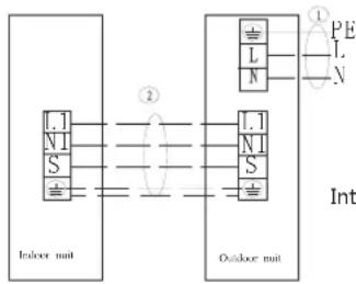
flowchart
graph LR
    subgraph_Indoor_mait["Indoor unit"]
        A1["."] --> B1["L"]
        A2["N"] --> B1
        A3["S"] --> B1
        B1 --> C1["N"]
        B1 --> D1["S"]
    end
    subgraph_Outdoor_mait["Outdoor unit"]
        E1["."] --> F1["L"]
        E2["N"] --> F1
        E3["S"] --> F1
        F1 --> G1["N"]
        F1 --> H1["S"]
    end
    I["PE"] --> J["①"]
    K["L"] --> L["②"]
    M["N"] --> N["②"]
    style I fill:#f9f,stroke:#333
    style K fill:#f9f,stroke:#333
POWER SUPPLY 220-240V/50Hz
Interconnection cords are shielded wire
Applicable for (220-240V/50Hz) single phase model
text_image
POWER SUPPLY 380-415V3N/50Hz PE L1 L2 L3 \ L1 L2 L3 N L1 N1 S Outdoor nulb ① ② L1 N1 S Indoor nulbInterconnection cords are shielded wire
Applicable for (380-415V/50Hz)≥ three phase model
Electric connection of indoor unit:
- Remove the cover plate of indoor unit electric appliance box.
- Connect the power supply line and signal line with related terminals ash shown in the figure.
- Open the wire pressing clip, pass the power supply line and signal line through the valve plate and firmly hold in the pressing clip.
- Install the electric appliance box board.
Note: Only the wiring methods of signal line and power supply line are shown in in the figure; the wiring methods please refer to the wiring schematic diagram of power sssusupply.
Power supply line specifications
| Model\Name | Outdoor power supply line (quantity, diameter)H05RN-F | Indoor power supply line(quantity, diameter)H05VV-F | Indoor /outdoor connection line(quantity, diameter) | Power supply method |
| Single phase 18K model | 3 × 1.5mm^2 | / | 4 × 1.0mm^2 | Outdoor Power Supply |
| Single phase 24K model | 3 × 2.5mm^2 | / | 4 × 1.0mm^2 | Outdoor Power Supply |
| Single phase ≥slant 36K model | 3 × 4mm^2 | / | 4 × 1.5mm^2 | Outdoor Power Supply |
| 3- phase ≥slant 36K model | 3 × 2.5mm^2 | / | 4 × 1.5mm^2 | Outdoor Power Supply |
Annex: Unit Package List
| I | Indoor unit paper box | |
| 1 | Indoor unit | 1 set |
| 2 | Install the paper board | 1 piece |
| 3 | Attachment package1: 8 hexagon nuts; 8 washer; 1 drainage hose, 2 hose clamps; 5 ribbons, 4 hoisting rods. Note: The details refer to the actual article. | 1 group |
| 4 | Attachment package 2: 1 Installation and Operation Instruction (including the product after-sales service card), 1 remote controller, 1 pair of 7# batteries (Cooling/heating machine, additional: 1 water plug, 1 drainage bent pipe) | 1 group |
| 5 | Attachment package 3: a single joint thermal insulation pipe each for high and low pressure pipe; a gasket each for large, medium and small size(available for model of higher than 7.0) | 1 group |
| II | Outdoor unit paper box | |
| 1 | Outdoor unit | 1 set |
| III | Indoor unit panel paper box | |
| 1 | Indoor unit panel | 1 pcs |
Packing ____ Inspection ____
natural_image
Abstract radial gradient pattern with no text or symbolsINFINITON
① Do not place the remote controller near the high temperature heat sources such as electric carpet or heating oven.
② Do not put the remote controller at the position directly exposed to the sunshine.
③ Be careful not to drop off from high position; otherwise it may be damaged.
④ There must have no barrier between signal receiver and remote controller of air conditioner which may affect the receiving and transmitting of signal.
⑤ Do not splash the liquid such as water onto the remote controller.
⑥ Do not place the weight onto the remote controller.
natural_image
Technical line drawing of a battery pack and its internal casing (no text or symbols)
natural_image
Isometric diagram of a mechanical assembly with layered components and a central component (no text or symbols)
natural_image
Pure technical line drawing of a mechanical or architectural component without any text, numbers, or symbolstext_image
1 - 1.5mabove 2/100