
IAN 066768 - Pump POWERFIX - Free user manual and instructions
Find the device manual for free IAN 066768 POWERFIX in PDF.


| Product Type | Electronic Measuring Device (Multimeter) |
| Model Number | IAN 066768 |
| Brand | Powerfix |
| Dimensions (approx.) | 150 x 80 x 35 mm |
| Weight (approx.) | 250 g |
| Power Supply | 2 x 1.5V AA batteries (not included) |
| Display | LCD with backlight |
| Measurement Functions | AC/DC voltage, resistance, continuity test, diode test |
| Safety Rating | CAT II 600V |
| Operating Temperature | 0 °C to 40 °C |
| Storage Temperature | -20 °C to 60 °C |
| Accessories Included | Test leads, manual |
| Cleaning | Wipe with a dry cloth; do not use solvents |
| Safety Precautions | Do not exceed rated voltage; remove batteries when not in use |
| Spare Parts Availability | Contact manufacturer or retailer; model-specific test leads |
| Repairability | No user-serviceable parts; refer to qualified personnel |
| General Information | For household and DIY use; read manual before first use |
Frequently Asked Questions - IAN 066768 POWERFIX
User questions about IAN 066768 POWERFIX
0 question about this device. Answer the ones you know or ask your own.
Ask a new question about this device
Download the instructions for your Pump in PDF format for free! Find your manual IAN 066768 - POWERFIX and take your electronic device back in hand. On this page are published all the documents necessary for the use of your device. IAN 066768 by POWERFIX.
USER MANUAL IAN 066768 POWERFIX
natural_image
Close-up of a water pump connecting to a pond with lily pads (no text or symbols visible)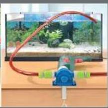
natural_image
Experimental setup with a blue instrument and red tubing over a green outdoor background (no visible text or symbols)
CONTENT PAGE
Safety instructions 2
Intended Usage 3
Technical Data 3
Items supplied 4
Overview of the appliance 4
Assembly material required 4
Assembly and connection 5
Disassembly of the drive shaft 7
Utilisation 8
Cleaning and care 8
Disposal 9
Declaration of conformity 9
Importer 9
Warranty and Service 10
Read these operating instructions carefully before using the appliance for the first time and preserve these instructions for later reference. Pass these instructions on to whoever may acquire the appliance at a future date.

To avoid the risk of accidents and damage to the appliance:
- Operate the pump ONLY when it is secured by the supplied mounting against jolting, twisting and canting.
- Check the pump for a faultfree condition before ever taking it into use. The pump may not be used if it shows signs of damage.

The drive shaft of the pump does not allow itself to be turned by hand. This does not indicate that the pump is defective.
- Use only hoses certified as being able to withstand a pressure of at least 3 bars (44 psi).
- Check the plug-in connectors on the hoses for firm seating.
- Take steps to ensure that the fluid being pumped cannot come into contact with the electric drill during pumping. Should it nonetheless occur, immediately remove the power plug.
- Avoid the intake of coarse dirt, otherwise the pump could be damaged. If needs be, use a filter on the suction hose.
- This appliance is not intended for use by children or other individuals whose physical, sensorial or intellectual abilities prevent safe usage of the appliance should they not receive support or supervision in the correct operation of the appliance. Children should be supervised to ensure that they do not play with the appliance.
This pump is intended for ...
- standard commercial right/left rotating electric drills with a 43 mm Euro-spindle and a gear-wheel rim chuck/quick-release chuck or drill chuck with SDS fitting, up to rotation speed of 3400 rpm,
- the pumping of cold or up to 40^ C warm fluids, such as non-potable or dirty water from fish tanks or ponds.
This pump is NOT intended for ...
- the pumping of flammable, explosive, poisonous or caustic liquids or foodstuffs.
- for industrial or commercial applications.
Technical Data
Capacity: max. 2,4 m
^3/h
Hose connection: 3/4" (19 mm)
Pressure: max. 3 bar
Delivery height: max. 30 m
Suction height: max. 3 m
Temperature of the fluid being pumped: max. 40^ C
Dry run time: max. 12 seconds
Rotation speed: max. 3400 rpm
Items supplied
- Pump
- Short drive shaft
- Long drive shaft
- Clamp fixing
- Mounting
- Open-ended spanner
- Storage box for the drive shafts and open-ended spanner
- This operating manual
Overview of the appliance
1 Pump
② Drive shaft of the pump
3 Short drive shaft (suitable for gear-wheel/quick-release chuck)
4 Long drive shaft (suitable for a drill chuck with SDS fitting)
⑤ Clamp fastening
6 Mounting
⑦ Electric drill (not supplied)
⑧ Recess for chuck key
9 Connection for suction hose
10 Connection for pressure hose
Assembly material required
- Philips-type screwdriver
- Flat-headed screwdriver
- Open-ended spanner (supplied)
Assemble the mounting ⑥ with the clamp fastening ⑤ onto a work surface, as shown in the illustration.
Alternatively, the mounting ⑥ can also be secured to a work surface with screws (assembly material not supplied).
When using a gear-wheel chuck and the short drive shaft ③...
Screw the short drive shaft ③ onto the drive shaft ② of the pump ①.
Insert the electric drill ⑦ with the chuck into the mounting ⑥.
Now push the pump ① onto the mounting ⑥ so that the drive shaft ③ projects into the chuck and the pins of the mounting ⑥ are located in the reception holes on the pump ①.
Now tighten the chuck with the chuck key through the recess ⑧ so firmly that the pump ① can no longer release itself from the mounting ⑥.
Tighten the cross-headed screw on the mounting ⑥ firmly, so that the drill ⑦ cannot jolt around.
Attach the suction hose to the connection ⑨ and the pressure hose to the connection ⑩. Pay heed to the direction of flow detailed on the pump ⑪.
When using a quick-release chuck and the short drive shaft ③...
Secure the short drive shaft ③ into the chuck.
Insert the electric drill ⑦, with the pre-assembled drive shaft ③ in the chuck, into the mounting ⑥.
Securely tighten the cross-head screw on the mounting ⑥ so that the drill ⑦ is being firmly held.
Now push the pump ① onto the mounting ⑥ so that the drive shaft ③ projects into the thread of the drive shaft ②, and the pins of the mounting ⑥ are located in the reception holes on the pump ①.
Let the drill ⑦ start to run in a clockwise rotation and at low revolutions and then guide the pump ① straight onto the drive shaft ③. The drive shaft ③ is thereby secured to the pump ①.
Attach the suction hose to the connection ⑨ and the pressure hose to the connection ⑩. Pay heed to the direction of flow detailed on the pump ⑪.
When using a chuck with SDS fitting and the long drive shaft ④...
Attach the long drive shaft 4 into the chuck.
Insert the electric drill ⑦, with the pre-assembled drive shaft ④ in the chuck, into the mounting ⑥.
Tighten the cross-headed screw on the mounting ⑥ firmly, so that the drill ⑦ cannot jolt around.
Now push the pump ① onto the mounting ⑥ so that the drive shaft ④ projects into the thread of the drive shaft ② and the pins of the mounting ⑥ are located in the reception holes on the pump ①.
Allow the electric drill ⑦ to run with a clockwise rotation and low revolutions and guide the pump ① straight on to the drive shaft ④. With this the drive shaft ④ will be fixated onto the pump ①.
Attach the suction hose to the connection ⑨ and the pressure hose to the connection ⑩. Pay heed to the direction of flow detailed on the pump ⑪.
Disassembly of the short drive shaft ③
Wheel rim chuck
Open the chuck with the chuck key through the recess ⑧ and then remove the pump ① from the mounting ⑥.
Unscrew the short drive shaft ③ by using a cross-headed screwdriver and the open-ended spanner from the pump ①.
Quick-release chuck
Using the open-ended spanner through the recess ⑧, counter screw the drive shaft ② of the pump ①.
Allow the electric drill ⑦ to run with an anti-clockwise rotation and low revolutions. The drive shaft ③ is thereby released from the pump ①.
Remove the pump ① from the mounting ⑥.
Remove the drive shaft ③ from the chuck.
Disassembly of the long drive shaft 4
Chuck with SDS fitting
Using the open-ended spanner through the recess, 8 counter screw the drive shaft 2 of the pump 1.
Allow the electric drill ⑦ to run with an anti-clockwise rotation and low revolutions. With this the drive shaft ④ will be released from the pump ①.
Remove the pump ① from the mounting ⑥.
Remove the drive shaft 4 from the chuck.
Attention!
The pump is self priming. If the pump ① does not start to suck up within 12 seconds, turn the drill ⑦ off immediately to avoid seizure. For this same reason, do not allow the pump ① to commence suction if the pressure hose on the discharge side is closed.
Place the open end of the suction hose into the liquid that is to be pumped. The suction hose may not be longer than 3 m. Ensure that the suction hose does not pull in air.
If the pump 1 does not commence suction, fill the hose with some water and then lift it so that the liquid runs before the pump.
Allow the drill ⑦, now the pump ①, to start-up – but not without supervision, so that you can react quickly in the event of danger. Absolutely ensure that the electric drill ⑦ is rotating to the right, as with normal drilling. Should the rotation speed of the electric drill ⑦ be adjustable, you can use this to regulate the discharge flow.
Turn the drill off immediately after the container is empty.
Cleaning and care
Clean the pump ① with a dry or lightly moistened cloth only. To avoid damage to the plastic surfaces, do not use solvents or abrasive cleaning agents. The pump is maintenance free.
Do not dispose of the appliance in your normal domestic waste.
Dispose of the appliance through an approved disposal centre or at your community waste facility.
Observe the currently applicable regulations. In case of doubt, please contact your waste disposal centre.

Dispose of all packaging materials in an environmentally friendly manner.
Declaration of conformity
We, Kompernaß GmbH, Burgstraße 21, D-44867 Bochum, declare with sole responsibility that the product described here, "Drill Pump 66768",
to which this declaration refers, complies fully with the valid requirements of the EU Directive 2006/42/EC (Machines) in the construction that is being marketed by us.
Should the product be modified in any way without our agreement, this declaration loses its validity.
Bochum, 04.14.2011
Hans Kompernaß
- Managing Director -
Importer
KOMPERNASS GMBH
BURGSTRASSE 21
44867 BOCHUM, GERMANY
www.kompernass.com
The warranty for this appliance is for 3 years from the date of purchase. The appliance has been manufactured with care and meticulously examined before delivery. Please retain your receipt as proof of purchase. In the event of a warranty claim, please make contact by telephone with our Service Department. Only in this way can a post-free despatch for your goods be assured.
The warranty covers only claims for material and manufacturing defects, but not for transport damage, for wearing parts or for damage to fragile components, e.g. buttons or batteries. This product is for private use only and is not intended for commercial use. The warranty is void in the case of abusive and improper handling, use of force and internal tampering not carried out by our authorized service branch. Your statutory rights are not restricted in any way by this warranty.
The warranty period will not be extended by repairs made under warranty. This applies also to replaced and repaired parts. Any damage and defects extant on purchase must be reported immediately after unpacking the appliance, at the latest, two days after the purchase date. Repairs made after the expiration of the warranty period are subject to payment.

Service Great Britain
Tel.: 0871 5000 720 (£ 0.10/Min.)
E-Mail: kompernass@lidl.gb
IAN 66768

Service Ireland
Tel.: 1890 930 034
(0,08 EUR/Min., (peak))
(0,06 EUR/Min., (off peak))
E-Mail: kompernass@lidl.ie
IAN 66768
SPIS TREČCI STRONA
TARTALOMJEGYZÉK OLDAL

- CONTENT PAGE
- To avoid the risk of accidents and damage to the appliance:
- Technical Data
- Items supplied
- Overview of the appliance
- Assembly material required
- When using a gear-wheel chuck and the short drive shaft ③...
- When using a quick-release chuck and the short drive shaft ③...
- When using a chuck with SDS fitting and the long drive shaft ④...
- Disassembly of the short drive shaft ③
- Wheel rim chuck
- Disassembly of the long drive shaft 4
- Chuck with SDS fitting
- Attention!
- Cleaning and care
- Declaration of conformity
- Importer
- Service Great Britain
- Service Ireland
- SPIS TREČCI STRONA
- TARTALOMJEGYZÉK OLDAL
Brand : POWERFIX
Model : IAN 066768
Category : Pump