
PM-211P - DJ Equipment Omnitronic - Free user manual and instructions
Find the device manual for free PM-211P Omnitronic in PDF.


| Product Type | DJ Mixer with MP3 Player |
| Model | PM-211P |
| Brand | Omnitronic |
| Input Channels | 2 stereo (Line/Phono) + 1 DJ Microphone (6.3 mm jack) |
| Outputs | Master Out (stereo RCA), Rec Out (stereo RCA), Headphones (6.3 mm stereo jack) |
| USB Port | USB Type A for MP3 playback (FAT32, up to 32 GB) |
| Frequency Range | 20 - 20000 Hz |
| Signal-to-Noise Ratio | > 75 dB |
| Total Harmonic Distortion | < 0.07 % |
| Power Supply | 230 V AC, 50 Hz via supplied power unit (device: protection class III) |
| Power Consumption | 3 W |
| Dimensions (L x W x H) | 180 x 140 x 65 mm |
| Weight | 1.2 kg |
| Crossfader | Yes, between Channel 1 and Channel 2 |
| Talkover Function | Yes, attenuates channels by 20 dB when active |
| Headphone Monitoring | Prefader CUE with CUE MIXING control |
| LED Level Meter | 6-digit, switchable between Master and CUE |
| MP3 Playback | USB devices with FAT32, files in root directory, alphabetical order, auto repeat |
| Operating Temperature | -5°C to +45°C |
| Humidity | ≤ 50 % at 45°C |
| Cleaning | Use soft lint-free damp cloth, no solvents |
| Warranty | Damages from unauthorized modifications or disregard of manual void warranty |
Frequently Asked Questions - PM-211P Omnitronic
User questions about PM-211P Omnitronic
0 question about this device. Answer the ones you know or ask your own.
Ask a new question about this device
Download the instructions for your DJ Equipment in PDF format for free! Find your manual PM-211P - Omnitronic and take your electronic device back in hand. On this page are published all the documents necessary for the use of your device. PM-211P by Omnitronic.
USER MANUAL PM-211P Omnitronic
natural_image
Pure electrical circuit lines without any symbolsA
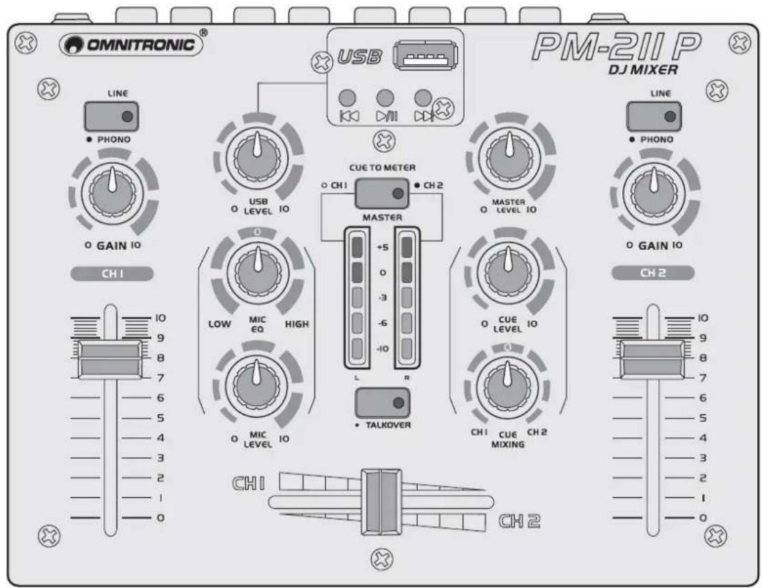
B
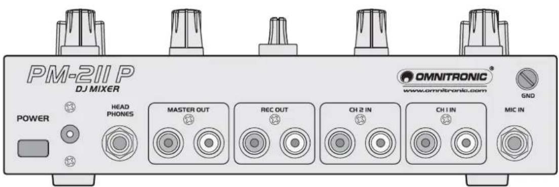
Inhaltsverzeichnis/
Table of contents
Deutsch
5.1 Installation 8
5.2 Anschlüsse....8
- BEDIENUNG 9
-
INTRODUCTION 13
-
SAFETY INSTRUCTIONS ...... 13
-
OPERATING DETERMINATIONS.... 14
-
Operating elements and connections ...... 15
-
SET UP....17
5.1 Installation 17
5.2 Connections 17
- OPERATION 18
6.1 Basic adjustment of the input channels 18
6.2 Adjustment of the output level.... 18
6.3 Crossfading between the input channels.... 18
6.4 Prefader listening to the input channels.... 18
6.5 Announcements via the DJ microphone 19
6.6 Playing MP3 files.... 19
- CLEANING AND MAINTENANCE 19
- PROBLEM CHART ...... 20
- TECHNICAL SPECIFICATIONS.... 20
This user manual is valid for the article number: 10006873
Keep this device away from rain and moisture! Unplug mains lead before opening the housing!
For your own safety, please read this user manual carefully before you initially start-up.
Every person involved with the installation, operation and maintenance of this device has to
- be qualified
- follow the instructions of this manual
- consider this manual to be part of the total product
- keep this manual for the entire service life of the product
- pass this manual on to every further owner or user of the product
- download the latest version of the user manual from the Internet
1. INTRODUCTION
Thank you for having chosen the OMNITRONIC mixer PM-211P. You have acquired a reliable and powerful device. If you follow the instructions given in this manual, we can assure you that you will enjoy this device for many years.
Unpack your mixer.
2. SAFETY INSTRUCTIONS
This device has left our premises in absolutely perfect condition. In order to maintain this condition and to ensure a safe operation, it is absolutely necessary for the user to follow the safety instructions and warning notes written in this user manual.

Important:
Damages caused by the disregard of this user manual are not subject to warranty. The dealer will not accept liability for any resulting defects or problems.
Please make sure that there are no obvious transport damages. Should you notice any damages on the power unit or on the casing, do not take the device into operation and immediately consult your local dealer.
This device falls under protection-class III. The device must be operated with an appropriate power unit.
Always plug in the power unit least. Make sure that the device is switched off before it is connected to the mains.
English
Keep away from heaters and other heating sources! If the device has been exposed to drastic temperature fluctuation (e.g. after transportation), do not switch it on immediately. The arising condensation water might damage your device. Leave the device switched off until it has reached room temperature.
Never put any liquids on the device or close to it. Should any liquid enter the device nevertheless, disconnect from mains immediately. Please let the device be checked by a qualified service technician before you operate it again. Any damages caused by liquids having entered the device are not subject to warranty!
Always disconnect from the mains, when the device is not in use or before cleaning it.
Please note that damages caused by manual modifications on the device or unauthorized operation by unqualified persons are not subject to warranty.
CAUTION: Turn the amplifier on last and off first! Keep away children and amateurs!
There are no serviceable parts inside the device. Maintenance and service operations are only to be carried out by authorized dealers.
3. OPERATING DETERMINATIONS
The DJ mixer PM-21 1P features two stereo input channels, one DJ microphone channel, and an MP3 player and is especially suitable for DJ applications.
This product is allowed to be operated with an alternating current of 12 V and was designed for indoor use only.
The device must only be operated with the included power unit. The power unit falls under protection-class 2 and the device under protection-class 3.
Do not shake the device. Avoid brute force when operating the device.
When choosing the installation spot, please make sure that the device is not exposed to extreme heat, moisture or dust. There should not be any cables lying around. You endanger your own and the safety of others!
The ambient temperature must always be between -5^ C and +45^ C. Keep away from direct insulation (particularly in cars) and heaters. The relative humidity must not exceed 50 % with an ambient temperature of 45^ C. This device must only be operated in an altitude between -20 and 2000 m over NN.
Never use solvents or aggressive detergents in order to clean the device! Rather use a soft and damp cloth.
Please use the original packaging if the device is to be transported.
Please consider that unauthorized modifications on the device are forbidden due to safety reasons!
If this device will be operated in any way different to the one described in this manual, the product may suffer damages and the guarantee becomes void. Furthermore, any other operation may lead to dangers like short-circuit, burns, electric shock, etc.
4. OPERATING ELEMENTS AND CONNECTIONS
FRONT PANEL
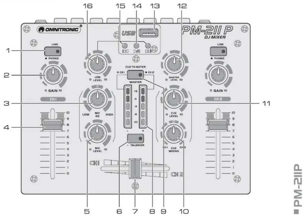
1 Input selector switches
For switching the rear inputs of channels 1 and 2 from line to phono input.
2 Gain controls
Adjust the input amplification for channels 1 and 2.
3 Tone control for the DJ microphone
4 Channel faders for channels 1 and 2
5 Level control for the DJ microphone
6 Talkover on/off
On/off switch for the talkover function. With the button engaged (red LED lights), the levels of the channels 1 and 2 are automatically attenuated by 20 dB when announcements are made with the DJ microphone.
7 Crossfader
For crossfading between channel 1 and channel 2.
8 Output level LED meter
Switchable 6-digit LED meter for the stereo master signal or the monitor signal within the range of -10 dB to +5 dB. In monitor mode, the prefader signal of channel 1 is displayed on the left side of the level meter and the prefader signal of channel 2 on the right side.
9 Selector switch LED level display
- Switch disenganged: indication of the master level
- Switch engaged: indication of the monitor level of channels 1 and 2 (red LED lights)
10 Control CUE MIXING
Fades between channel 1 and channel 2 for the headphones output.
11 Level control for the headphones output
12 Master level control
13 USB port
USB port for connecting a USB storage device. The MP3 player's signal is directly sent to the master outputs; it is not affected by the TALKOVER switch and cannot be routed to the headphones output.
14 Button [▶II]
For switching between play and pause.
15 Buttons [◀] and [▶]
- Short actuation: for title selection
- Long actuation: for fast forward/reverse
16 Level control for the MP3 player
REAR PANEL
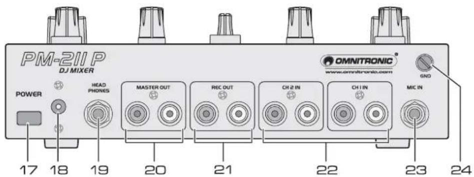
PM-2IIP
17 Power on/off
Turns the mixer on and off.
18 Power connection
Plug in the supplied power unit here.
19 Headphones output
6.3 mm jack for connecting stereo headphones.
20 Master output
Stereo output (RCA) for connecting an amplifier or other units with line level input.
21 Recording output
Stereo output (RCA) for connecting a recording unit. The recording level is independent of the position of the master control.
22 Line/phono inputs
Stereo inputs (RCA) for channels 1 and 2 for connecting units with line level outputs (e. g. CD player) or turntables with magnetic system.
With the front input selector switches the inputs can be switched from line level to phono level.
23 Microphone input
6.3 mm jack for connecting a dynamic DJ microphone.
24 Ground terminal
Ground clamping screw for turntables connected to channels 1 and 2.
5. SET UP
5.1 Installation
Set up the mixer on a plane surface. Please make sure that there is enough space around the unit for ventilation to improve heat dissipation. Steady overheating will damage the unit.
5.2 Connections
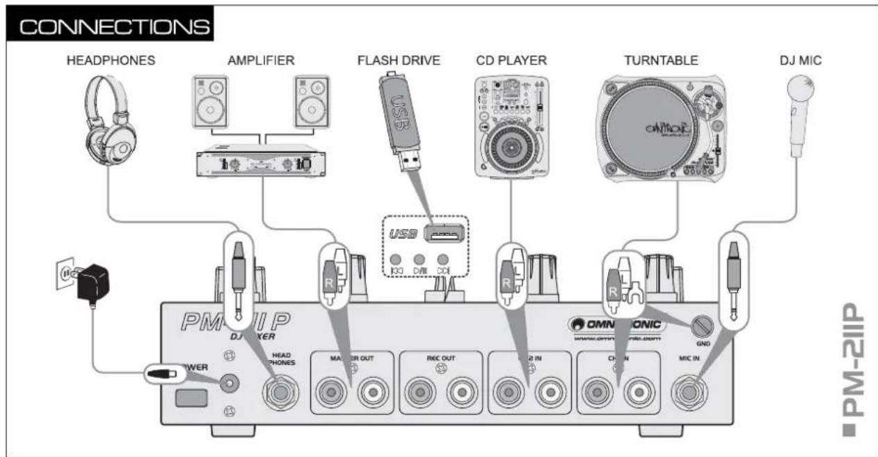
flowchart
graph TD
    A["HEADPHONES"] --> B["AMPLIFIER"]
    B --> C["FLASH DRIVE"]
    C --> D["CD PLAYER"]
    D --> E["TURNTABLE"]
    E --> F["DJ MIC"]
    G["PM-2IP"] --> H["DJ MHzER"]
    H --> I["POWER"]
    I --> J["Headphones"]
    J --> K["DAIR"]
    K --> L["Flash Drive"]
    L --> M["USB"]
    M --> N["CD"]
    N --> O["CDI"]
    P["OMNIONIC"] --> Q["GND"]
    R["CHAIN"] --> S["MIC IN"]
    T["R"] --> U["R"]
    V["R"] --> W["R"]
    X["R"] --> X
    Y["R"] --> X
    Z["R"] --> X
    style A fill:#f9f,stroke:#333
    style G fill:#ccf,stroke:#333
    style P fill:#cfc,stroke:#333
    style R fill:#fcc,stroke:#333
    style T fill:#cff,stroke:#333
    style U fill:#ffc,stroke:#333
    style V fill:#fcc,stroke:#333
    style W fill:#ffc,stroke:#333
    style X fill:#fcc,stroke:#333
    style Y fill:#fcc,stroke:#333
    style Z fill:#fcc,stroke:#333
Switch off the mixer prior to connecting any units or to changing any existing connections.
1 Connect units with line level output (e.g. CD players) or turntables with magnetic system to the corresponding RCA jacks of channels 1 and 2 (white jack = left channel; red jack = right channel). If your turntable is equipped with a separate ground lead, connect it to the clamping screw.
- For units with line level output, leave the respective input selector switch disengaged.
- For turntables, engage the input selector switch (red LED lights).
2 Connect a dynamic DJ microphone with an unbalanced 6.3 mm plug to the microphone input MIC.
3 Connect the amplifier to the unbalanced RCA master output.
4 For sound recordings, connect the recording unit to the output REC OUT. The recording level is independent of the position of the master control.
5 The input channels can be monitored via stereo headphones. Connect the headphones to the 6.3 mm jack HEAPHONES.
6 Connect the cable of the power unit to the power input and the power unit to a power outlet.
- Use the mixer only with the supplied power unit. Always disconnect the mains connector when you wish to change connections, move the unit to a different place or if it is not used for a longer period.
6. OPERATION
Prior to switching on, set the master control to zero to avoid damage to the hearing by a volume which is too high when switching on. Switch on the mixer with the power switch and then the connected units. After operation, switch off the mixer with the power switch.
6.1 Basic adjustment of the input channels
1 First set both gain controls and the crossfader to mid-position.
2 The master control determines the total level of all connected audio sources. Set the control to approx. 2/3 of its maximum.
3 Press the selector switch CUE TO METER to switch on the monitoring mode (red LED lights). Now the LED level display indicates the prefader signal of channel 1 on the left side and the prefader signal of channel 2 on the right side.
4 Via the LED level display, adjust the input amplification of both input channels with the channel faders. An optimum level control is obtained if level values in the 0 dB range are shown at average volume. If the red LEDs of the meter light up, there is an overload of the channel signal. After level adjustment, the cannel faders should be at approx. 2/3 of their maximum. With the faders advanced only slightly or very far, the level must be matched by adjusting the input amplification. Turn up or turn back the respective gain control accordingly.
6.2 Adjustment of the output level
The output signal is fed to the adjustable master output and to the recording output without individual level control.
1 Disengage the switch CUE TO METER. Now the LED level display indicates the master signal.
2 Via the LED level display, adjust the master signal to an optimum level with the master control. Usually an optimum level control is obtained if the LED level display shows values in the 0 dB range at average volume. However, if the output level at the master output is too high for the following unit, the master signal must be controlled to a corresponding lower level.
3 The recording signal at the output REC OUT is not affected by the master control.
6.3 Crossfading between the input channels
The crossfader allows crossfading between both input channels:
• crossfader moved to the left: fade-in of channel 1 and fade-out of channel 2
• crossfader moved to the right: fade-in of channel 2 and fade-out of channel 1
- For hearing the signals of the two channels at the same level, set the crossfader to mid-position.
6.4 Prefader listening to the input channels
The cue function allows monitoring each of the input channels via headphones connected to the jack HEADPHONES even if the corresponding channel is faded out. Thus, it is possible, e.g. to time the moment for fading in an audio source.
1 For prefader listening to a channel, adjust the control CUE MIXING: Turn the control to the left to monitor channel 1, turn the control to the right to monitor channel 2. In mid-position, both channels can be heard at the same volume.
2 Adjust the desired headphones volume with the control CUE LEVEL.
6.5 Announcements via the DJ microphone
1 Adjust the volume of the microphone announcement with the control MIC LEVEL.
2 Adjust the desired sound with the tone control MIC EQ: Turn the control to the left for a more bass-emphasized sound, turn the control to the right for a more treble-emphasized sound.
3 To improve the audibility of an announcement during the current music program, press the button TALKOVER (red LED lights) to activate the talkover function. Then during a microphone announcement, the levels of channels 1 and 2 are automatically attenuated by 20 dB.
6.6 Playing MP3 files
The integrated MP3 player is intended for the background program and not for the main program. Accordingly, the MP3 player's signal is directly sent to the master output; it is not affected by the TALKOVER switch and cannot be routed to the headphones output.
1 Insert a USB device into the USB port. After loading a device, it is selected as the playback medium and read in. Press the button [▶II] to start the playback of the first title. To interrupt the playback, press the button [▶II] once again.
2 Adjust the desired volume for the MP3 player with the level control USB LEVEL.
3 With the buttons [◀] and [▶], you can skip titles in forward or backward direction and start fast forward and reverse:
- short actuation of the button [▶]: skip to the next title
- short actuation of the button [◀]: skip to the previous title
- long actuation of the button [▶]: fast forward
- long actuation of the button [◀]: fast reverse
4 To remove a USB device, disconnect it from the USB port. Prior to removing a device, always terminate the playback with the button [▶II]. Otherwise damage or loss of data may occur.

Regarding USB devices
- This unit supports USB devices with the file system FAT32 and with a capacity up to 32 GB.
- This unit does not recognize folders. All MP3 files must be stored in the root directory of the memory. The files will be played in alphabetical order.
- The MP3 player features an auto repeat function, i. e. all titles of the data carrier are continuously played.
- This unit supports MSC (Mass Storage Class) USB storage devices 1.0, 1.1, 2.0 including external portable flash memory devices and digital audio players. However, hard discs, optical discs such as external CD/DVD drives will not be recognized. Depending on the device used, proper playback may not be possible with all USB devices.
- If a USB device is not recognized at the first try, remove it and insert it again.
7. CLEANING AND MAINTENANCE

DANGER TO LIFE!
Disconnect from mains before starting maintenance operation!
We recommend a frequent cleaning of the device. Please use a soft lint-free and moistened cloth. Never use alcohol or solvents!
There are no serviceable parts inside the device. Maintenance and service operations are only to be carried out by authorized dealers.
Should you need any spare parts, please use genuine parts.
Should you have further questions, please contact your dealer.
8. PROBLEM CHART
| PROBLEM CAUSE REMEDY | ||
| The power does not turn on. | · The power cable is not connected. | · Connect the cable to a power outlet. |
| There is little or no sound. | · The input selector switch is in the wrong position.· The connection cable was not connected properly or not connected at all.· The terminal or plug is dirty.· The master level is too low. | · Set the selector switch to the correct signal source.· Connect the cable properly.· Clean and reconnect.· Increase the level with the master control. |
| No function in MP3 player operation. | · The USB device was not recognized.· The USB device is not compatible. | · Remove the device and re-insert it.· Try using another device. |
| There is noise or distortion. | · The master level is too high.· The input level is too high. | · Via the output meter, adjust the master level to an optimum level with the master control.· Via the output meter, adjust the channel to an optimum level with the gain control. |
9. TECHNICAL SPECIFICATIONS
| Power supply: 230 V AC, 50 Hz ~ via supplied power unit | |
| Power consumption: 3 W | |
| USB port: USB type A | |
| Available storage media: USB devices up to 32 GB (FAT32) | |
| Playback format: MP3, WAV | |
| Inputs: | |
| Line/phono: 2 x stereo RCA | |
| DJ microphone: 6.3 mm jack, unbal. | |
| Outputs: | |
| Master: stereo RCA | |
| Record: stereo RCA | |
| Headphones: 6.3 mm stereo jack (≥32 Ω) | |
| Frequency range: 20-20000 Hz | |
| S/N ratio: >75 dB | |
| Distortion: <0.07 % | |
| Dimensions (LxWxH): 180 x 140 x 65 mm | |
| Weight: 1.2 kg | |
Please note: Every information is subject to change without prior notice. 19.02.2013 ©
- Inhaltsverzeichnis/
- Table of contents
- Deutsch
- INTRODUCTION
- SAFETY INSTRUCTIONS
- Important:
- English
- OPERATING DETERMINATIONS
- OPERATING ELEMENTS AND CONNECTIONS
- FRONT PANEL
- Input selector switches
- Gain controls
- Tone control for the DJ microphone
- Channel faders for channels 1 and 2
- Level control for the DJ microphone
- Talkover on/off
- Crossfader
- Output level LED meter
- Selector switch LED level display
- Control CUE MIXING
- Level control for the headphones output
- Master level control
- USB port
- Button [▶II]
- Buttons [◀] and [▶]
- Level control for the MP3 player
- REAR PANEL
- Power on/off
- Power connection
- Headphones output
- Master output
- Recording output
- Line/phono inputs
- Microphone input
- Ground terminal
- SET UP
- Installation
- Connections
- OPERATION
- Basic adjustment of the input channels
- Adjustment of the output level
- Crossfading between the input channels
- Prefader listening to the input channels
- Announcements via the DJ microphone
- Playing MP3 files
- Regarding USB devices
- CLEANING AND MAINTENANCE
- DANGER TO LIFE!
- PROBLEM CHART
- TECHNICAL SPECIFICATIONS
Brand : Omnitronic
Model : PM-211P
Category : DJ Equipment