GR-DVX8 - Camcorder JVC - Free user manual and instructions
Find the device manual for free GR-DVX8 JVC in PDF.
| Sensor Type | CCD 1/4" Progressive Scan |
| Optical Zoom | 10x |
| Lens Aperture | F 1.8 |
| Focal Length | 3.8 mm to 38 mm |
| Filter Diameter | 27 mm |
| Recording Format | Mini DV (DV SD format) |
| Tape Speed SP Mode | 18.8 mm/s - 80 min max |
| Tape Speed LP Mode | 12.5 mm/s - 120 min max |
| Digital Audio | PCM 32 kHz 4 tracks 12 bit / 48 kHz 2 tracks 16 bit |
| LCD Screen | 2.5 inches TFT active matrix, 270-degree rotation |
| Electronic Viewfinder | Color LCD 0.44 inch |
| Digital Connection | DV I/O IEEE 1394 FireWire 4 pins |
| Analog Video Output | 1 V (peak to peak), 75 ohms |
| Battery Power Supply | DC 7.2 V |
| AC Adapter Power Supply | DC 6.3 V |
| Weight (bare, without cassette or battery) | Approximately 500 g |
| Weight (with cassette and battery) | Approximately 575 g |
| Dimensions (W x H x D) | 51 x 125 x 97 mm |
| Operating Temperature | 0°C to 40°C |
Frequently Asked Questions - GR-DVX8 JVC
User questions about GR-DVX8 JVC
0 question about this device. Answer the ones you know or ask your own.
Ask a new question about this device
Download the instructions for your Camcorder in PDF format for free! Find your manual GR-DVX8 - JVC and take your electronic device back in hand. On this page are published all the documents necessary for the use of your device. GR-DVX8 by JVC.
USER MANUAL GR-DVX8 JVC
Please visit our Homepage on the World Wide Web and answer our Consumer Survey (in English only):
http://www.jvc-victor.co.jsp/english/index-e.html
Mini DY PAL

DIGITAL
STILLCAMERA
INSTRUCTIONS
| CONTENTS | |
| AUTOMATIC DEMONSTRATION 5 | |
| GETTING STARTED 6 - 15 | |
| RECORDING 16 - 39 | |
| Basic Recording For Video 16 | |
| Basic Recording For Digital Still Camera (D.S.C.) 19 | |
| Basic Recording For Video And D.S.C. 20 | |
| Advanced Features For Video And D.S.C. 22 | |
| PLAYBACK 40 - 55 | |
| Basic Playback For Video 40 | |
| Advanced Features For Video 41 | |
| Basic Playback For D.S.C. 45 | |
| Advanced Features For D.S.C. 48 | |
| CONNECTIONS 56 - 59 | |
| Basic Connections 56 | |
| Advanced Connections 58 | |
| DUBBING 60 - 65 | |
| Dubbing To A VCR 60 | |
| Dubbing From A VCR 61 | |
| Dubbing To A Video Unit Equipped With A DV Connector 62 | |
| Dubbing From A Video Unit Equipped With A DV Connector 63 | |
| Dubbing Images Stored In A MultiMediaCard To A Tape 64 | |
| Dubbing Images Recorded On A Tape To A MultiMediaCard 65 | |
| USING THE REMOTE | |
| CONTROL UNIT 66 - 77 | |
| Slow-Motion Playback, Frame-By-Frame Playback and Playback Zoom 68 | |
| Playback Special Effects 69 | |
| Random Assemble Editing 70 | |
| For More Accurate Editing 74 | |
| Audio Dubbing 76 | |
| Audio Dubbing Using Digital Sound Effects 77 | |
| USER MAINTENANCE 78 | |
| TROUBLESHOOTING 79 - 84 | |
| INDEX 85 - 92 | |
| Docking Station 85 | |
| Controls, Connectors And Indicators 86 | |
| Indications 88 | |
| CAUTIONS 93 - 95 | |
| TERMS 96 - 97 | |
| SPECIFICATIONS 98 - 99 |
Dear Customer,
Thank you for purchasing this digital video camera. Before use, please read the safety information and precautions contained in the following pages to ensure safe use of this product.
Using This Instruction Manual
- All major sections and subsections are listed in the Table Of Contents on the cover page.
- Notes appear after most subsections. Be sure to read these as well.
- Basic and advanced features/operation are separated for easier reference.
It is recommended that you . . .
..... refer to the Index (pgs. 85 - 92) and familiarize yourself with button locations, etc. before use.
... read thoroughly the Safety Precautions. They contain extremely important information regarding the safe use of this product.
You are recommended to carefully read the cautions on pages 93 through 95 before use.
SAFETY PRECAUTIONS
IMPORTANT (for owners in the U.K.)
Connection to the mains supply in the United Kingdom. DO NOT cut off the mains plug from this equipment. If the plug fitted is not suitable for the power points in your home or the cable is too short to reach a power point, then obtain an appropriate safety approved extension lead or consult your dealer.
BE SURE to replace the fuse only with an identical approved type, as originally fitted, and to replace the fuse cover.
If nonetheless the mains plug is cut off be sure to remove the fuse and dispose of the plug immediately, to avoid possible shock hazard by inadvertent connection to the mains supply.
If this product is not supplied fitted with a mains plug then follow the instructions given below:
DO NOT make any connection to the Larger Terminal coded E or Green.
The wires in the mains lead are coloured in accordance with the following code:
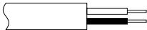
Blue to N (Neutral) or Black Brown to L (Live) or Red
If these colours do not correspond with the terminal identifications of your plug, connect as follows:
Blue wire to terminal coded N (Neutral) or coloured black.
Brown wire to terminal coded L (Live) or coloured Red.
If in doubt — consult a competent electrician.
WARNING:
TO PREVENT FIRE OR SHOCK HAZARD, DO NOT EXPOSE THIS UNIT TO RAIN OR MOISTURE.
CAUTIONS:
- To prevent shock, do not open the cabinet. No user serviceable parts inside. Refer servicing to qualified personnel.
- When you are not using the AC Power Adapter/ Charger for a long period of time, it is recommended that you disconnect the power cord from AC outlet.
NOTES:
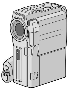
- The rating plate (serial number plate) and safety caution are on the bottom and/or the back of the main unit.
- The rating plate (serial number plate) of the AC Power Adapter/Charger is on its bottom.
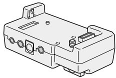
- The rating plate (serial number plate) of the Docking Station is on its bottom.
This camcorder is designed to be used with PAL-type colour television signals. It cannot be used for playback with a television of a different standard. However, live recording and LCD monitor/viewfinder playback are possible anywhere. Use the BN-V507U/V514U battery packs and, to recharge them, the provided multi-voltage AC Power Adapter/Charger. (An appropriate conversion adapter may be necessary to accommodate different designs of AC outlets in different countries.)
When the equipment is installed in a cabinet or on a shelf, make sure that it has sufficient space on all sides to allow for ventilation (10 cm or more on both sides, on top and at the rear).
Do not block the ventilation holes.
(If the ventilation holes are blocked by a newspaper, or cloth etc. the heat may not be able to get out.)
No naked flame sources, such as lighted candles, should be placed on the apparatus.
When discarding batteries, environmental problems must be considered and the local rules or laws governing the disposal of these batteries must be followed strictly.
The apparatus shall not be exposed to dripping or splashing.
Do not use this equipment in a bathroom or places with water.
Also do not place any containers filled with water or liquids (such as cosmetics or medicines, flower vases, potted plants, cups etc.) on top of this unit.
If water or liquid is allowed to enter this equipment, fire or electric shock may be caused.)
Do not point the lens or the viewfinder directly into the sun. This can cause eye injuries, as well as lead to the malfunctioning of internal circuitry. There is also a risk of fire or electric shock.
CAUTION!
The following notes concern possible physical damage to the camcorder and to the user.
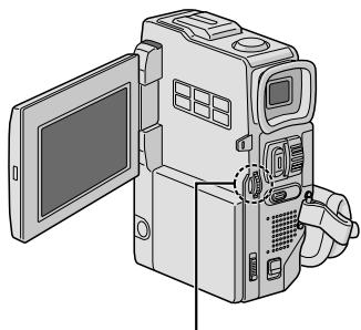
When carrying, be sure to always securely attach and use the provided shoulder strap. Carrying or holding the camcorder by the viewfinder and/or the LCD monitor can result in dropping the unit, or in a malfunction.
Take care not to get your finger caught in the cassette holder cover. Do not let children operate the camcorder, as they are particularly susceptible to this type of injury.
Do not use a tripod on unsteady or unlevel surfaces. It could tip over, causing serious damage to the camcorder.
CAUTION!
Attaching the camcorder to the Docking Station with cables (Audio/Video, S-Video, Editing, DC, etc.) connected, then leaving it on top of the TV is not recommended, as tripping on the cables will cause the camcorder to fall, resulting in damage.
Mini

PAL
MultiMediaCard
This camcorder is designed exclusively for the digital video cassette and MultiMediaCard. Only cassettes marked "MultiMediaCard" and memory cards marked "MultiMediaCard" can be used with this unit.
Before recording an important scene . . .
......make sure you only use cassettes with the Mini DV mark MiND
...... make sure you only use memory cards with the mark MultiMediaCard .
.... remember that this camcorder is not compatible with other digital video formats.
..... remember that this camcorder is intended for private consumer use only. Any commercial use without proper permission is prohibited. (Even if you record an event such as a show, performance or exhibition for personal enjoyment, it is strongly recommended that you obtain permission beforehand.)
SOME DO'S AND DON'TS ON THE SAFE USE OF EQUIPMENT
This equipment has been designed and manufactured to meet international safety standards but, like any electrical equipment, care must be taken if you are to obtain the best results and safety is to be assured.
DO read the operating instructions before you attempt to use the equipment.
DO ensure that all electrical connections (including the mains plug, extension leads and interconnections between pieces of equipment) are properly made and in accordance with the manufacturer's instructions. Switch off and withdraw the mains plug when making or changing connections.
DO consult your dealer if you are ever in doubt about the installation, operation or safety of your equipment.
DO be careful with glass panels or doors on equipment.
DONT continue to operate the equipment if you are in any doubt about it working normally, or if it is damaged in any way — switch off, withdraw the mains plug and consult your dealer.
DONT remove any fixed cover as this may expose dangerous voltages.
DON'T leave equipment switched on when it is unattended unless it is specifically stated that it is designed for unattended operation or has a standby mode. Switch off using the switch on the equipment and make sure that your family knows how to do this. Special arrangements may need to be made for infirm or handicapped people.
DONT use equipment such as personal stereos or radios so that you are distracted from the requirements of road safety. It is illegal to watch television whilst driving.
DON'T listen to headphones at high volume, as such use can permanently damage your hearing.
DONT obstruct the ventilation of the equipment, for example with curtains or soft furnishings. Overheating will cause damage and shorten the life of the equipment.
DON'T use makeshift stands and NEVER fix legs with wood screws — to ensure complete safety always fit the manufacturer's approved stand or legs with the fixings provided according to the instructions.
DON'T allow electrical equipment to be exposed to rain or moisture.
ABOVE ALL
NEVER let anyone especially children push anything into holes, slots or any other opening in the case - this could result in a fatal electrical shock;
NEVER guess or take chances with electrical equipment of any kind — it is better to be safe than sorry!
- Docking Station CU-V502E
- AC Power Adapter/Charger AA-V51EG or AA-V51EK
Battery Pack BN-V507U
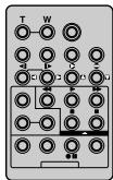
Remote Control Unit RM-V716U
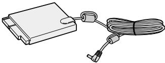
- DC Cord

- AAA (R03) Battery x 2 (for remote control unit)

- Core Filter x 2 (for optional S-Video cable and Audio/Video (RCA plug - RCA plug) cable)

- MultiMediaCard (8 MB) (Already inserted in the camcorder)

CD-ROM
The CD ROM contains the following 11 software programmes:
MultiMediaNavigator
- JLIP Video Capture
- JLIP Video Producer
- Picture Navigator (for Windows®)
- Picture Navigator (for Macintosh®)
- CardNavigator
Video Player
JVC Video Decoder
- Cable Adapter

- Cleaning Cloth

Audio/Video Cable (Ø3.5 mini-plug to RCA plug)

- Editing Cable (One plug has 3 rings around the pin, and the other has 1 ring around the pin.)

- JLIP Cable (Both plugs have 3 rings around the pin.)

PC Connection Cable
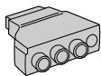
How To Attach Core Filters
Attach the provided Core Filters to an optional S-Video cable or Audio/Video (RCA plug - RCA plug) cable. Core Filters reduce interference.
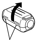
1
Stopper
Release the stoppers on both ends of the Core Filter.
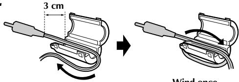
2
Run the cable through the Core Filter, leaving approx. 3cm of cable between the cable plug and the Core Filter. Wind the cable around the outside of the Core Filter as shown in the illustration.
- Wind the cable so that it is not slack.
NOTE:
Take care not to damage the cable.
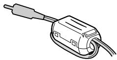
3
Close the Core Filter until it clicks shut.
- When connecting cables, attach the end with the Core Filter to the camcorder.
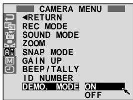
Automatic Demonstration takes place when "DEMO. MODE" is set to "ON" (factory-preset).
Available when the POWER Switch is set to "CAMERA" and no cassette is in the camcorder.
Performing any operation during the demonstration stops the demonstration temporarily. If no operation is performed for more than 1 minute after that, the demonstration will resume.
- "DEMO. MODE" remains "ON" even if the camcorder power is turned off.
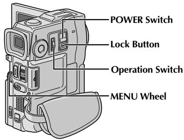
- To cancel Automatic Demonstration, set the Operation Switch to "M" and set the POWER Switch to "CAMERA" while pressing down the Lock Button located on the switch, then press the MENU wheel twice while the demo is in progress. This takes you directly to the demo mode's Setting Menu (so you will not have to go through the Menu Screen). Rotate the MENU wheel to select "OFF" and press it. The normal screen appears.
MENU Wheel
| Battery pack | Charging time |
| BN-V507U | approx. 1 hr. 30 min. |
| BN-V514U (optional) | approx. 3 hrs. |
Power
This camcorder's 2-way power supply system lets you choose the most appropriate source of power. Do not use provided power supply units with other equipment.
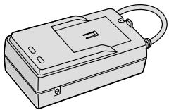
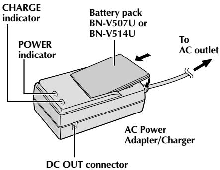
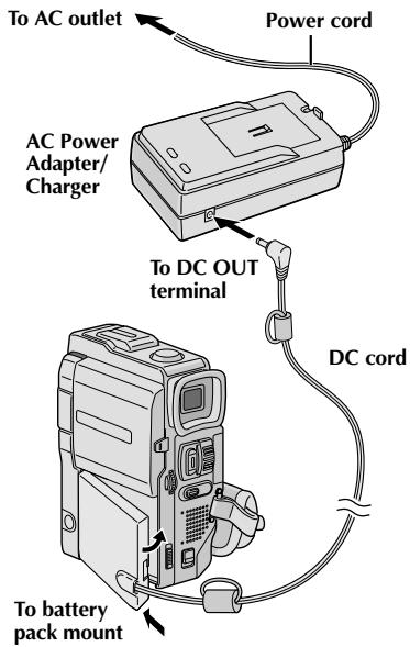
CHARGING THE BATTERY PACK
1 Make sure you unplug the camcorder's DC cord from the AC Power Adapter/Charger. Plug the AC Adapter/ Charger's power cord into an AC outlet. The POWER indicator lights.
2 Attach the battery pack with the mark aligned with the corresponding marks on the AC Power Adapter/Charger. The CHARGE Indicator begins blinking to indicate charging has started.
3 When the CHARGE indicator stops blinking but stays lit, charging is finished. Pull the battery out. Remember to unplug the AC Adapter/Charger's power cord from the AC outlet.
NOTES:
- Perform charging where the temperature is between 10^ and 35^ . 20^ to 25^ is the ideal temperature range for charging. If the environment is too cold, charging may be incomplete.
- Charging times noted above are for a fully discharged battery pack.
- Charging time varies according to the ambient temperature and the status of the battery pack.
- To avoid interference with reception, do not use the AC Power Adapter/Charger near a radio.
- If you connect the camcorder's DC cord to the adapter during battery charging, power is supplied to the camcorder and charging stops.
- Since the AC Power Adapter/Charger processes electricity internally, it becomes warm during use. Be sure to use it only in well-ventilated areas.
- When charging the battery pack for the first time or after a long storage period, the CHARGE indicator may not light. In this case, remove the battery pack from the AC Power Adapter/Charger, then try charging again.
- If the battery operation time remains extremely short even after having been fully charged, the battery is worn out and needs to be replaced. Please purchase a new one.

Lithium-ion is vulnerable in colder temperatures.

About Batteries
DANGER! Do not attempt to take the batteries apart, or expose them to flame or excessive heat, as it may cause a fire or explosion.
WARNING! Do not allow the battery or its terminals to come in contact with metals, as this can result in a short circuit and possibly start a fire.
The Benefits Of Lithium-Ion Batteries
Lithium-ion battery packs are small but have a large power capacity. However, when one is exposed to cold temperatures (below 10^ ), its usage time becomes shorter and it may cease to function. If this happens, place the battery pack in your pocket or other warm, protected place for a short time, then re-attach it to the camcorder. As long as the battery pack itself is not cold, it should not affect performance.
(If you're using a heating pad, make sure the battery pack does not come in direct contact with it.)
ATTENTION:
Before detaching the power source, make sure that the camcorder's power is turned off. Failure to do so can result in a camcorder malfunction.
INFORMATION:
VU-V856KIT is a set composed of the BN-V856U battery pack and AA-V80EG or AA-V80EK AC Power Adapter/Charger. Read the VU-V856KIT's instruction manuals before using.
It is impossible to charge the BN-V856U battery pack using the provided AC Power Adapter/ Charger. Use the optional AA-V80EG or AA-V80EK AC Power Adapter/Charger.
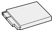
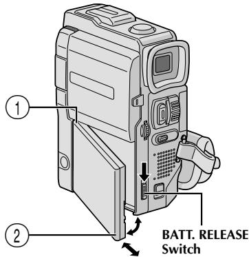
USING THE BATTERY PACK
1 Insert the terminal end ① of the battery pack into the battery pack mount, then firmly push the end ② of the battery pack in the direction of the arrow until it locks into place as shown in the illustration.
- If the battery pack is attached in the wrong position, a malfunction may occur.
To Detach The Battery Pack...
.... while sliding down BATT. RELEASE, detach it.
Approximate recording time
| Battery pack | LCD monitor on/ Viewfinder off | LCD monitor off/ Viewfinder on | ||
| ① | ② | ① | ② | |
| BN-V507U | 45 min. | 50 min. | 55 min. | 1 hr. |
| BN-V514U (optional) | 1 hr. 35 min. | 1 hr. 45 min. | 1 hr. 55 min. | 2 hrs. 5 min. |
| BN-V856U (optional) | 6 hrs. 40 min. | 7 hrs. | 8 hrs. | 8 hrs. 30 min. |
① When using GR-DVX10
② When using GR-DVX9
NOTES:
- Recording time is reduced significantly under the following conditions:
- Zoom or Record-Standby mode is engaged repeatedly.
- The LCD monitor is used repeatedly.
- The playback mode is engaged repeatedly.
- Before extended use, it is recommended that you prepare enough battery packs to cover 3 times the planned shooting time.
USING AC POWER
Use the AC Power Adapter/Charger (connect as shown in the illustration).
NOTES:
The provided AC Power Adapter/Charger features automatic voltage selection in the AC range from 110 V to 240 V.
For other notes, pg. 6.
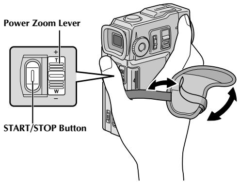
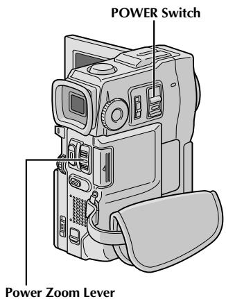
Grip Adjustment

Separate the Velcro strip.

Pass your right hand through the loop and grasp the grip.

Adjust so that your thumb and fingers can easily operate the START/STOP Button and Power Zoom Lever. Refasten the Velcro strip.
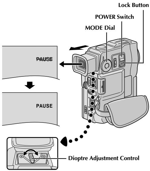
Viewfinder Adjustment

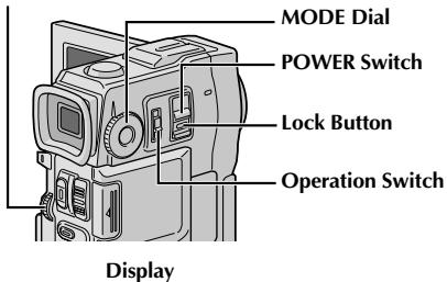
Set the POWER Switch to "CAMERA" while pressing down the Lock Button located on the switch and set the MODE Dial to any position.

Pull out the viewfinder fully.

Turn the Dioptré Adjustment Control until the indications in the viewfinder are clearly focused.
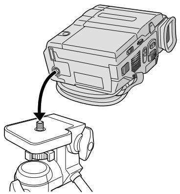
Tripod Mounting

Align the screw on the tripod with the camera's mounting socket. Then tighten the screw.
CAUTION:
When using a tripod, be sure to open and extend its legs fully to stabilise the camcorder. To prevent damage to the unit caused by falling over, do not use a small-sized tripod.

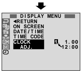
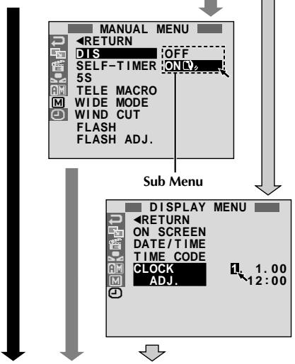
DISPLAY MENU
Date/Time Settings
The date/time is recorded onto the tape at all times, but its display can be turned on or off during playback (pg. 41).
1 Set the Operation Switch to "M" and set the POWER Switch to "CAMERA" while pressing down the Lock Button located on the switch, then open the LCD monitor fully or pull out the viewfinder fully. The POWER lamp lights and the camcorder is turned on.
Press the MENU wheel. The Menu Screen appears.
3 Rotate the MENU wheel to select "O". Press it and "DISPLAY MENU" appears.
4 Rotate the MENU wheel to select "CLOCK ADJ." Press it and "day" is highlighted. Rotate the MENU wheel to input the day. Press it. Repeat to input the month, year, hour and minute. Rotate the MENU wheel to select "RETURN", and press it twice. The Menu Screen closes.
Built-in Clock's Rechargeable Lithium Battery
To store the date/time in memory, the clock's rechargeable lithium battery is integrated in the camcorder. While the camcorder is connected to an AC outlet using the AC Power Adapter/Charger, or while the battery pack attached to the camcorder continues to supply power, the clock's rechargeable lithium battery is always charged. However, if the camcorder is not used for approx. 3 months, the clock's lithium battery will become discharged and the date/time stored in memory will be lost. When this occurs, first connect the camcorder to an AC outlet using the AC Power Adapter/Charger for over 24 hours to charge the clock's rechargeable lithium battery. Then perform the date/time setting before using the camcorder. Note that the camcorder can be used without setting the date/time.
NOTE:
Even if you select "CLOCK ADJ.", if the parameter is not highlighted the camcorder's internal clock continues to operate. Once you move the highlight bar to the first date/time parameter (day), the clock stops. When you finish setting the minute and press the MENU wheel, the date and time begin operation from the date and time you just set.
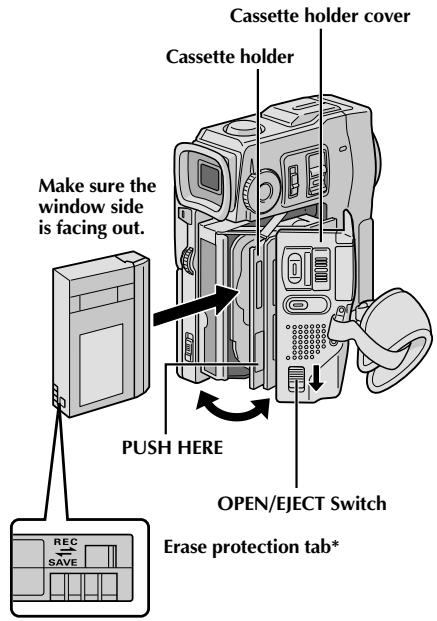
* To Protect Valuable Recordings . . .
... slide the erase protection tab on the back of the tape in the direction of "SAVE". This prevents the tape from being recorded over. To record on this tape, slide the tab back to "REC" before loading it.
Loading/Unloading A Cassette
The camcorder needs to be powered up to load or eject a cassette.
1 Slide down and hold OPEN/EJECT in the direction of the arrow then pull the cassette holder cover open until it locks. The cassette holder opens automatically.
- Do not touch internal components.
2 Insert or remove a tape and press "PUSH HERE" to close the cassette holder.
- Once the cassette holder is closed, it recedes automatically. Wait until it recedes completely before closing the cassette holder cover.
- When the battery's charge is low, you may not be able to close the cassette holder cover. Do not apply force. Replace the battery with a fully charged one before continuing.
3 Close the cassette holder cover firmly until it locks into place.
Approximate recording time
- It takes a few seconds for the cassette holder to open. Do not apply force.
- If you wait a few seconds and the cassette holder does not open, close the cassette holder cover and try again. If the cassette holder still does not open, turn the camcorder off then on again.
- If the tape does not load properly, open the cassette holder cover fully and remove the cassette. A few minutes later, insert it again.
- When the camcorder is suddenly moved from a cold place to a warm environment, wait a short time before opening the cassette holder cover.
- Closing the cassette holder cover before the cassette holder comes out may cause damage to the camcorder.
- Even when the camcorder is switched off, a cassette can be loaded or unloaded. After the cassette holder is closed with the camcorder switched off, however, it may not recede. It is recommended to turn the power on before loading or unloading.
- When resuming recording, once you open the cassette holder cover a blank portion will be recorded on the tape or a previously recorded scene will be erased (recorded over) regardless of whether the cassette holder came out or not. See page 21 for information about recording from the middle of a tape.

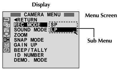
Recording Mode Setting
Set the tape recording mode depending on your preference.
1 Set the Operation Switch to "M" and set the POWER Switch to "CAMERA" while pressing down the Lock Button located on the switch, then open the LCD monitor fully or pull out the viewfinder fully. The POWER lamp lights and the camcorder is turned on.
Press the MENU wheel. The Menu Screen appears.
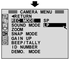
3 Rotate the MENU wheel to select "A" and press it. "CAMERA MENU" appears.
4 Rotate the MENU wheel to select "REC MODE" and press it. The Sub Menu appears. Select "SP" or "LP" by rotating the MENU wheel and press it. Rotate the MENU wheel to select "RETURN", and press it twice. The Menu Screen closes.
- Audio Dubbing (pg. 76) is impossible on a tape recorded in the LP mode.
- "LP" (Long Play) is more economical, providing 1.5 times the recording time.
NOTES:
- If the recording mode is switched during recording, the playback picture will be blurred at the switching point.
It is recommended that tapes recorded in the LP mode on this camcorder be played back on this camcorder. - During playback of a tape recorded on another camcorder, blocks of noise may appear or there may be momentary pauses in the sound.
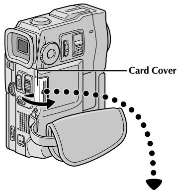
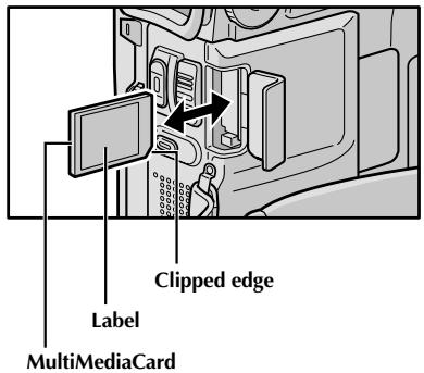
Loading A MultiMediaCard
The provided MultiMediaCard is already inserted in the camcorder when you receive the camcorder.
1 Make sure the camcorder's power is off.
Open the card cover.
2 Insert the MultiMediaCard clipped edge first.
- Do not touch the terminal on the reverse side of the label.
To close the card cover, push it until you hear a click.
NOTES:
- Be sure to use only MultiMediaCards marked "MultiMediaCard".
- Some brands of MultiMediaCards are not compatible with this camcorder. Before purchasing a MultiMediaCard, consult its manufacturer or dealer.
To Unload A MultiMediaCard . . .
... in step 3 push the MultiMediaCard, which then comes out of the camcorder automatically. Pull it out and close the card cover.
ATTENTION:
Do not insert/remove the MultiMediaCard while the camcorder is turned on, as this may cause the MultiMediaCard to be corrupted or cause the camcorder to become unable to recognize whether or not the card is installed.
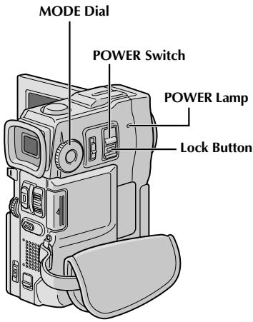

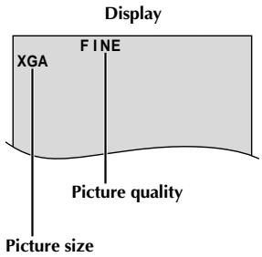
Picture Quality/Size Mode Setting
Picture quality and size can be selected to best match your needs. Four different modes are available: XGA (1024 x 768 pixels) FINE, XGA STD, VGA (640 x 480 pixels) FINE and VGA STD, listed in order of quality.
1
Set the POWER Switch to "CAMERA" while pressing down the Lock Button located on the switch and set the MODE Dial to "DSC", then open the LCD monitor fully. The POWER lamp lights and the camcorder is turned on.
2
Press IMAGE SIZE/RES. until the desired mode appears.
Approximate Number of Storable Images
| Picture Quality/Size Mode | MultiMediaCard | ||
| 4 MB (optional) | 8 MB (provided, with Sound Effects pre-stored) | 8 MB (optional) | |
| XGA FINE | 12 | 21 | 24 |
| XGA STD | 36 | 64 | 75 |
| VGA FINE | 26 | 46 | 54 |
| VGA STD | 76 | 133 | 155 |
NOTES:
- The number of storable images depends on the selected Picture Quality/Size mode as well as the composition of the subjects in the images.
- When the MODE Dial is set to "DUAL", only the picture quality can be set.
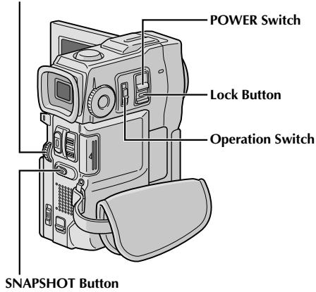
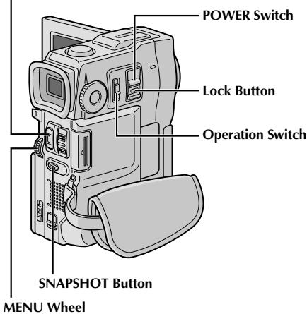
To turn on the camcorder, set the POWER Switch to any operation mode except "OFF" while pressing down the Lock Button located on the switch.
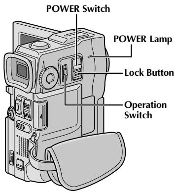
When the POWER Switch is set to "MEMORY", the type of file (IMAGE, E-MAIL CLIP or SOUND) is displayed. When set to "CAMERA" or "PLAY/PC", there is no indication.

When the Operation Switch is set to "A", "F. AUTO" appears. When set to "M", there is no indication.

Operation Mode
Choose the appropriate operation mode according to your preference using the POWER Switch, Operation Switch and MODE Dial.
| POWER Switch Position |
| CAMERA: Allows you to record on a tape or in the MultiMediaCard. |
| OFF: Allows you to switch off the camcorder. |
| PLAY/PC: Allows you to play back a recording on the tape or to transfer a still image recorded on the tape or in the MultiMediaCard to a computer. |
| MEMORY: Allows you to display an image stored in the MultiMediaCard. |
| Operation Switch Position |
| M (Manual): Allows you to set various recording functions using the Menus. If you want more creative capabilities than Full Auto recording, try this mode. |
| A (Full Auto): Allows you to record using NO special effects or manual adjustments. Suitable for standard recording. |
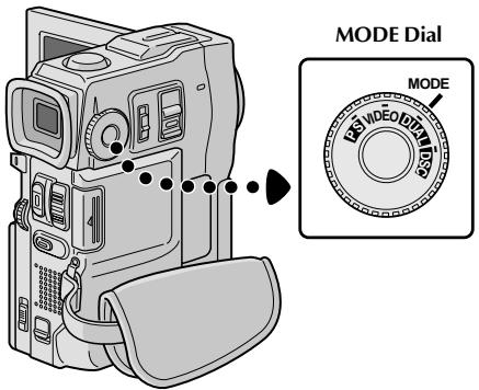
The following indications appear in the upper left corner, depending on the MODE Dial position.
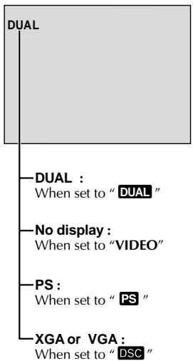
| MODE Dial Position | Function |
| DUAL | • Allows you to record video on a tape and store still images in a MultiMediaCard simultaneously (║ pg. 24). • File size of still images: 640 x 480 pixels • Video quality is the same as in the VIDEO mode. |
| VIDEO | • Allows you to record video and still images on a tape. Approx. 6 seconds of a still image is inserted between video recordings (║ pg. 18). • Zoom magnification over 10X is available (║ pg. 20, 27). |
| PS (Progressive mode) | • Allows you to record moving images (successive jitter-free still images) with superior quality on a tape (║ pg. 22). The still images can also be processed on a PC or printed out. • Zoom magnification over 10X is available (║ pg. 20, 27). •Playback of images recorded in this mode is not smooth. |
| DSC | • Allows you to record still images in a MultiMediaCard (║ pg. 13, 19). • File size: 1024 x 768 pixels (XGA), 640 x 480 pixels (VGA) |
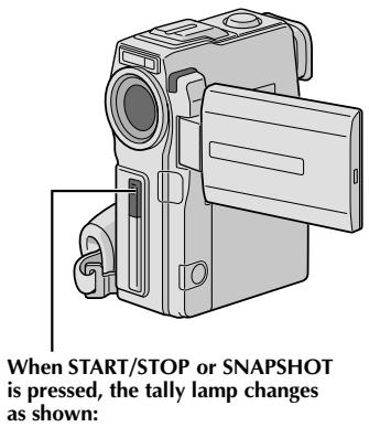
Tally lamp (lights while recording is in progress)
NOTE:
You should already have performed the procedures listed below. If not, do so before continuing.
Power (13 pg. 6)
- Grip Adjustment (F pg. 8)
- Viewfinder Adjustment (13 pg. 8)
- Load A Cassette (15 pg. 10)
- Recording Mode Setting (pg. 11)
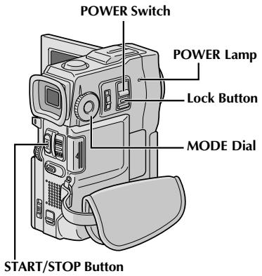
1 Set the MODE Dial to "VIDEO" and set the POWER Switch to "CAMERA" while pressing down the Lock Button located on the switch.
Shooting while using the viewfinder: Make sure the LCD monitor is closed and locked. Pull out the viewfinder fully.
- Be sure to pull out the viewfinder until you hear a click, otherwise it may be pushed back in during use.
Shooting while using the LCD monitor: Make sure the viewfinder is pushed back in. Open the LCD monitor fully.
- The POWER lamp lights and the camcorder enters the Record-Standby mode. "PAUSE" is displayed.
Press START/STOP. "REC" appears while recording is in progress.
To Stop Recording . . .
... press START/STOP. The camcorder re-enters the Record-Standby mode.
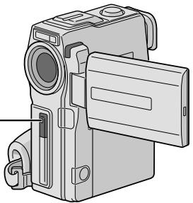
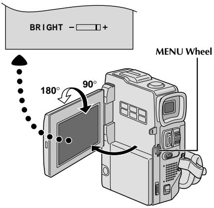
To Adjust The Brightness Of The Display
... rotate the MENU wheel until the bright level indicator on the display moves and the appropriate brightness is reached.
- It is also possible to adjust the brightness of the viewfinder.
NOTES:
- When you use the LCD monitor outdoors in direct sunlight, the LCD monitor may be difficult to see. If this happens, use the viewfinder instead.
- The image will not appear simultaneously in the LCD monitor and the viewfinder.
- The cassette holder cannot be opened unless a power supply is attached.
- There may be a delay after you open the cassette holder cover until the cassette holder opens. Do not use force.
- Once the cassette holder is closed, it recedes automatically. Wait until it recedes completely before closing the cassette holder cover.
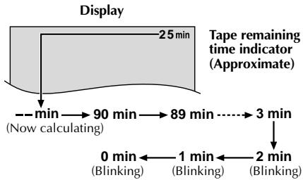
- The time required to calculate and display the remaining tape length, and the accuracy of the calculation, may vary according to the type of tape used.
- "TAPE END" appears when the tape reaches its end, and the power goes off automatically if left in this condition for 5 minutes. "TAPE END" also appears when a cassette at its end is loaded.
- If the Record-Standby mode continues for 5 minutes, the camcorder's power shuts off automatically. To turn the camcorder on again, push back and pull out the viewfinder again or close and re-open the LCD monitor.
- When a blank portion is left between recorded scenes on the tape, the time code is interrupted and errors may occur when editing the tape. To avoid this, refer to "Recording from the middle of a tape" (13 pg. 21).
- During recording, sound is not heard from the speaker. To hear the sound, connect optional headphones to the headphone connector. The sound volume is at the level it was adjusted to during playback (13 pg. 40).
To turn the tally lamp off during recording, pg. 26, 27.
To remove the indications from the camcorder's display during recording, pg. 26, 29.

Self-Recording
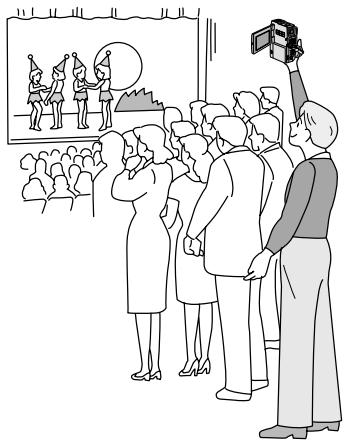
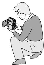
JOURNALISTIC SHOOTING
In some situations, different shooting angles may provide more dramatic results. Hold the camcorder in the desired position and tilt the LCD monitor in the most convenient direction. It can rotate 270^ (90° downward, 180° upward).
SELF-RECORDING
You can shoot yourself while viewing your own image in the LCD monitor. Open the LCD monitor and tilt it upward 180^ so that it faces forward, then point the lens toward yourself and start recording.
MENU Wheel
Display
Menu Screen

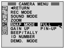
FULL
Snapshot mode with no frame*

PIN-UP
Pin-Up mode
- There is the sound effect of a shutter closing.
When the MODE Dial is set to "PS", snapshot recording will be performed with higher quality (43 pg. 22).
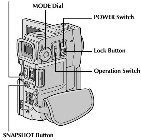
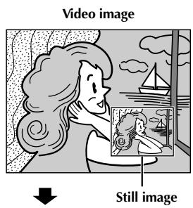
Snapshot (For Video Recording)
This feature lets you record still images that look like photographs onto a tape.
SNAPSHOT MODE SELECTION
1 Set the POWER Switch to "CAMERA" while pressing down the Lock Button located on the switch and the MODE Dial to "VIDEO" or "PS", then set the Operation Switch to "M". Pull out the viewfinder fully or open the LCD monitor fully.
Press the MENU wheel. The Menu Screen appears.
3 Rotate the MENU wheel to select "图" . Press it and "CAMERA MENU" appears.
4 Rotate the MENU wheel to select "SNAP MODE", then press it.
5 Rotate the MENU wheel to select the desired Snapshot mode, then press it. Rotate the MENU wheel to select "RETURN" and press it twice. The Menu Screen closes.
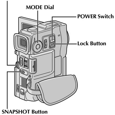
SNAPSHOT RECORDING
1 Press SNAPSHOT.
If you press during Record-Standby . . .
.... "PHOTO" appears and a still image will be recorded for approx. 6 seconds, then the camcorder re-enters the Record-Standby mode.
If you press during Recording . . .
.... "PHOTO" appears and a still image will be recorded for approx. 6 seconds, then the normal recording resumes.
To use the flash, pg. 30.
Motor Drive Mode
Keeping SNAPSHOT pressed provides an effect similar to serial photography. (Interval between still images: approx. 1 second)
NOTES:
To remove the shutter sound, "BEEP/TALLY" on pg. 27.
- If Snapshot recording is not possible, "PHOTO" blinks when SNAPSHOT is pressed.
- If Programme AE with special effects (FF pg. 36) is engaged, certain modes of Programme AE with special effects are disabled during Snapshot recording. In such a case, the icon blinks.
- If SNAPSHOT is pressed when "DIS" is set to "ON" (13 pg. 28), the Stabiliser will be disabled.
- To dub images recorded on a tape to a MultiMediaCard, pg. 65.
To reduce the Red-Eye effect in the subject's eyes when the flash fires, pg. 30.
- During playback as well, all snapshot modes are available when "OOP" is set to "OFF" in the Menu Screen (C) pg. 41).
- When a headphone set is connected to the headphone connector, the shutter sound is not heard from the speaker, however it is recorded onto the tape.
MENU Wheel
Total number of shots
Displays the approximate total number of shots that can be stored, including those already taken. The number increases or decreases depending on the shots stored, the Picture Quality/Size mode, MODE Dial
setting,etc.
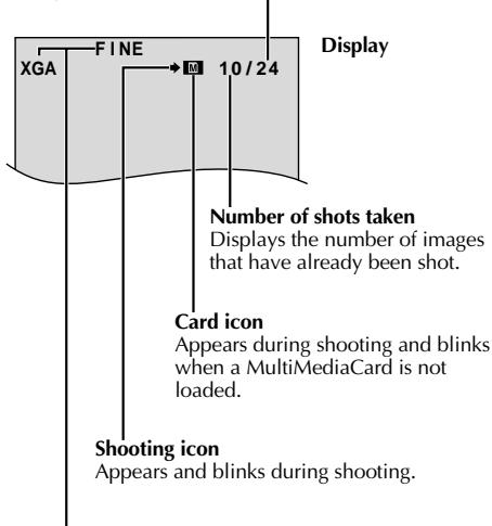
Picture Quality/Size mode
Displays the Picture Quality/Size mode of the stored image. There are 4 modes available: XGA FINE, XGA STD, VGA FINE, VGA STD (in order of quality) (pg. 13).

FULL
Snapshot mode with no frame
There is the sound effect of a shutter closing.
Basic Shooting (Snapshot)
You can use your camcorder as a Digital Still Camera for taking snapshots.
NOTE:
You should already have performed the procedures listed below. If not, do so before continuing.
Power (pg. 6)
- Grip Adjustment (15 pg. 8)
Viewfinder Adjustment (pg. 8)
- Loading A MultiMediaCard (https://pg.12)
- Picture Quality/Size Mode Setting (13 pg. 13)
1 Set the MODE Dial to "DSC" and the POWER Switch to "CAMERA" while pressing down the Lock Button located on the switch. Open the LCD monitor fully or pull out the viewfinder fully.
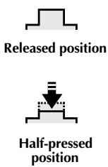
2 Press SNAPSHOT halfway. The screen becomes a still image, which is captured into the camcorder's memory. However, it is not recorded until SNAPSHOT is pressed fully.
- At this moment, if you release SNAPSHOT, snapshot recording will be cancelled.
Press SNAPSHOT fully.
The image is recorded in the MultiMediaCard.
- Still images are recorded in the snapshot mode with no frame.
To use the flash, pg. 30.
To Delete Unwanted Still Images...
.... when unwanted still images are stored in the MultiMediaCard or its memory is full, refer to "Deleting Files" (13 pg. 49) and delete unwanted still images.
To Remove The Shutter Sound . . .
.... when you do not want to hear the shutter sound, set BEEP/TALLY to "OFF" on the Menu Screen (pg. 26, 27). The sound is no longer heard from the speaker.
NOTES:
- Even if "DIS" is set to "ON" (13 pg. 28), the Stabiliser will be disabled.
- If Snapshot recording is not possible, "PHOTO" blinks when SNAPSHOT is pressed.
- If Programme AE with special effects (Fg. 36) is engaged, certain modes of Programme AE with special effects are disabled during Snapshot recording. In such a case, the icon blinks.
- If shooting is not performed for approx. 5 minutes when the POWER Switch is set to "CAMERA" and power is supplied from the battery pack, the camcorder shuts off automatically to save power. To perform shooting again, close the LCD monitor and re-open it. When using the viewfinder, push back it in and pull it out again.
- The Motor Drive mode (FF pg. 18) is disabled when the MODE Dial is set to "DSS".
- To reduce the Red-Eye effect in the subject's eyes when the flash fires, pg. 30.
- When a headphone set is connected to the headphone connector, the shutter sound is not heard from the speaker.
- Still images taken are compliant to DCF (Design rules for Camera File systems). They do not have any compatibility with devices which are not compliant to DCF.
- In the XGA mode, images shot using a 680,000-pixel Progressive Scan CCD (effective area: 630,000 pixels, 962 × 654 pixels) are converted and stored in the XGA mode file size (1024 x 768 pixels).
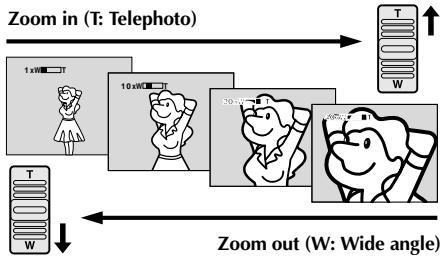
FEATURE: Zooming
PURPOSE:
To produce the zoom in/out effect, or an instantaneous change in image magnification.
OPERATION:
Zoom In
Slide the Power Zoom Lever towards "T".
Zoom Out
Slide the Power Zoom Lever towards "W".
The further you slide the Power Zoom Lever, the quicker the zoom action.
NOTES:
- Focusing may become unstable during Zooming. In this case, set the zoom while in Record-Standby, lock the focus by using the manual focus (Fig. 25), then zoom in or out in Record mode.
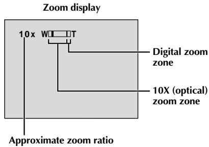
- Zooming is possible to a maximum of 200X, or it can be switched to 10X magnification using the optical zoom (F pg. 27).
- Zoom magnification of over 10X is done through Digital image processing, and is therefore called Digital Zoom.
- During Digital zoom, the quality of image may suffer.
-
Digital zoom cannot be used in the following cases:
-
When digital image processing, such as Picture Wipe/Dissolve (pg. 34, 35) or Video Echo (pg. 36), is activated.
-
When the MODE Dial is set to "DUAL" or "DSC".
-
Macro shooting (as close as approx. 5 cm to the subject) is possible when the Power Zoom Lever is set all the way to "W". Also see "TELE MACRO" in the Menu Screen on page 28.
NOTE: Recording From The Middle Of A Tape
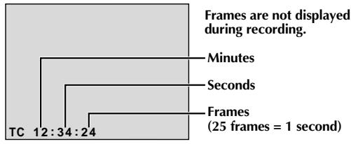
Time Code
During recording, a time code is recorded on the tape. This code is to confirm the location of the recorded scene on the tape during playback.
If recording starts from a blank portion, the time code begins counting from "00:00:00"
(minute:second:frame). If recording starts from the end of a previously recorded scene, the time code continues from the last time code number.
To perform Random Ensemble Editing (pg. 70 - 75), time code is necessary. If during recording a blank portion is left partway through the tape, the time code is interrupted. When recording is resumed, the time code starts counting up again from "00:00:00". This means the camcorder may record the same time codes as those existing in a previously recorded scene. To prevent this, perform "Recording From The Middle of A Tape" below in the following cases;
- When shooting again after playing back a recorded tape.
- When power shuts off during shooting.
- When a tape is removed and re-inserted during shooting.
- When shooting using a partially recorded tape.
- When shooting on a blank portion located partway through the tape.
- When shooting again after shooting a scene then opening/closing the cassette holder cover.
Display
Recording From The Middle Of A Tape
- Play back a tape or use Blank Search (L3 pg. 43) to find the spot at which you want to start recording, then engage the Still Playback mode (L3 pg. 40).
- Set the POWER Switch to "CAMERA" while pressing down the Lock Button located on the switch, then start recording.
NOTES:
The time code cannot be reset.
- During fast-forwarding and rewinding, the time code indication does not move smoothly.
- The time code is displayed only when "TIME CODE" is set to "ON" (13 pg. 29, 41).
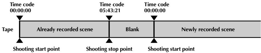
When a blank portion is recorded on a tape
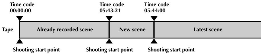
Proper recording
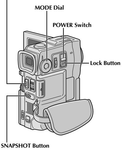
START/STOP Button
Progressive Mode Recording
This mode lets you record moving images (successive jitter-free still images) onto a tape. Images can then played back jitter-free, with superior quality. High-resolution still images can also be processed on a personal computer or can be printed out (pg. 59).
1 Set the MODE Dial to "PS", then set the POWER Switch to "CAMERA" while pressing down the Lock Button located on the switch. Pull out the viewfinder fully or open the LCD monitor fully.
2 To start Progressive Mode Recording, press START/ STOP.
To End Progressive Mode Recording . . .
... press START/STOP. The camcorder enters the Record-Standby mode.
NOTES:
- When an image recorded using the Progressive Mode is played back, the image may not look natural.
- When the MODE Dial is set to "PS", Picture Wipe/Dissolve (13 pg. 34) and some Programme AE with special effects (15 pg. 36) cannot be used.
- If SNAPSHOT is pressed in the PS mode, a snapshot will be recorded with higher quality than in VIDEO mode. (13 pg. 18).
Description of Progressive Scan CCD
Progressive Scan is a special image sensing method which, unlike conventional interlace scanning, is able to pick up all the lines of picture information in one Scan. Since the Progressive Scan CCD is capable of outputting 50 full Frames* per second — twice the amount of conventional systems — it is able to deliver a high quality picture even when its output signal is converted to a format that can be viewed on a TV screen.
- A PAL TV screen image is composed of 25 Frames per second. 1 Frame is made up of 2 Fields.

1 Frame
1. Regular shooting of moving images
Records 25 odd and 25 even image Fields, for a total of 50 per second. Since there is a time lag between an odd and even Field, when they are combined to make 1 Frame the part of the image that is moving appears as image jitter. However, during normal playback, the moving picture looks smooth and natural.
2. Progressive mode shooting of moving images (Progressive Mode Recording 13 pg. 22)
Scan A is recorded, divided into an odd- and even-number Field, and then Scan B is skipped. Scans C and D are handled in the same way as Scans A and B, as illustrated below, thereby recording 25 Frames per second.
Since each recorded odd- and even-number Field originates from the same Scan there is no time lag between them, and so when they are combined into a Frame and a still image is displayed on a TV or PC monitor the picture does not look jittery. However, when moving images are played back, the picture can look unnatural.


Dual Shooting
Lets you record images on a tape and store still images in a MultiMediaCard simultaneously. In other words, it is possible to store still images in the MultiMediaCard without interrupting image recording on the tape.
1 Set the POWER Switch to "CAMERA" while pressing down the Lock Button located on the switch and the MODE Dial to "DUAL". Pull out the viewfinder fully or open the LCD monitor fully.
2 While recording to a tape, press SNAPSHOT halfway. A still image is displayed in the lower right corner of the screen where the video image being recorded is displayed.
- At this moment, if you release SNAPSHOT, snapshot recording will be cancelled.
Press SNAPSHOT fully. The displayed still image is stored in the MultiMediaCard.
NOTES:
- If SNAPSHOT is pressed in the Record-Standby mode, only a still image is stored in the MultiMediaCard. Video recording does not take place.
- If SNAPSHOT is pressed when "DIS" is set to "ON" (13 pg. 28), the Stabiliser will be disabled.
- The Stabiliser is less effective in the DUAL mode than in other modes.
The flash is disabled during video recording. - Still images are stored in the MultiMediaCard in VGA mode file size (13 pg. 15).
- When the MODE Dial is set to "DUAL", all Fade/Wipe Effects and some Programme AE with special effects cannot be used (13 pg. 34 - 36).
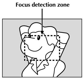

FEATURE: Auto Focus
PURPOSE:
The camcorder's Full Range AF system offers continuous shooting ability from close-up (as close as approx. 5 cm to the subject) to infinity.
However, correct focus may not be obtainable in the situations listed below (in these cases use manual focusing):
- When two subjects overlap in the same scene.
- When illumination is low.*
- When the subject has no contrast (difference in brightness and darkness), such as a flat, one-colour wall, or a clear, blue sky.*
- When a dark object is barely visible in the viewfinder.*
- When the scene contains minute patterns or identical patterns that are regularly repeated.
- When the scene is affected by sunbeams or light reflecting off the surface of a body of water.
- When shooting a scene with a high-contrast background.
- The following low-contrast warnings appear blinking: ▲, △, ▶ and ▼
NOTES:
- If the lens is smeared or blurred, accurate focusing is not possible. Keep the lens clean, wiping with a piece of soft cloth if it gets dirty. When condensation occurs, wipe with a soft cloth or wait for it to dry naturally.
- When shooting a subject close to the lens, zoom out first (13 pg. 20). If zoomed-in in the auto focus mode, the camcorder may automatically zoom out depending on the distance between the camcorder and the subject. This will not occur when "TELE MACRO" (13 pg. 28) is activated.
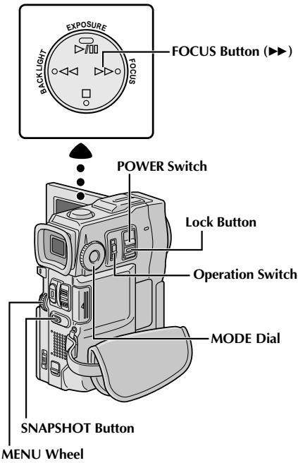
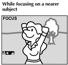
FEATURE: Manual Focus
PURPOSE:
To obtain correct focus.
OPERATION:
1) If you are using the viewfinder, you should already have made the necessary viewfinder adjustments (pg. 8).
2) Set the Operation Switch to "M" and set the POWER Switch to "CAMERA" while pressing down the Lock Button located on the switch, then press FOCUS (▶). The manual focus indicator appears.
3) To focus on a farther subject, rotate the MENU wheel towards "+" .▶" appears and blinks. To focus on a nearer subject, rotate the MENU wheel towards "−". "▲" appears and blinks.
4) Press the MENU wheel. Focus adjustment is complete.
To reset to Auto Focus, press FOCUS (▶) twice or set the Operation Switch to "A".
If FOCUS () is pressed once, the camcorder will enter the focus adjustment mode again.
NOTES:
- Be sure to focus the lens in the maximum telephoto position when you use the Manual Focus mode. If you focus in on a subject in the wide-angle position, sharply focused images cannot be obtained when zoomed up because the depth-of-field is reduced at longer focal lengths.
- When the focus level cannot be adjusted any further or closer, "▲" or "■" will blink.
Display
Menu Screen


Normal Screen
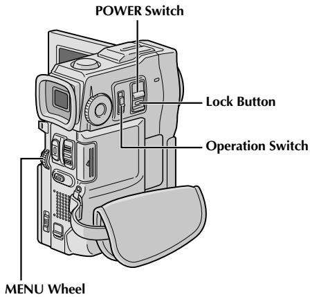
Using Menus For Detailed Adjustment
This camcorder is equipped with an easy-to-use, on-screen menu system that simplifies many of the more detailed camcorder settings (pg. 27 - 29).
1 Set the Operation Switch to "M" and set the POWER
Switch to "CAMERA" while pressing down the Lock Button located on the switch, then pull out the viewfinder fully or open the LCD monitor fully.
Press the MENU wheel. The Menu Screen appears.
3 Rotate the MENU wheel to select the desired function icon, and press it. The selected function menu appears.
Function menu setting depends on the function.
If you have selected "G", "W" or "Z" ...
... see pg. 27.
If you have selected "A", "C" or "D" ...
... go to step 5.
5 Rotate the MENU wheel to select the desired function and press it. The Sub Menu appears.
Then, rotate the MENU wheel to select the parameter, and press it. Selection is complete.
6 Rotate the MENU wheel to select "RETURN" and press it twice. The Menu Screen closes.
- The icon represents "END".
Menu Screen Explanations
| FADER/WIPE | Refer to "Fade/Wipe Effects" (pg. 34, 35). | ||
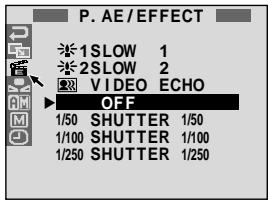
| P.AE/EFFECT | Refer to "Programme AE With Special Effects" (pg. 36). | ||
| W.BALANCE | Refer to "White Balance Adjustment" and "Manual White Balance Operation" (pg. 39). | ||
| REC MODE | Allows you to set the recording mode (SP or LP) depending on your preference (pg. 11). | ||
| SOUND MODE | 12 BIT | Enables video recording of stereo sound on four separate channels, and is recommended for use when performing audio dubbing. (Equivalent to the 32 kHz mode of previous models) | |
| 16 BIT | Enables video recording of stereo sound on two separate channels. (Equivalent to the 48 kHz mode of previous models) | ||
| ZOOM | 10X | When set to "10X" while using digital zoom, the zoom magnification will reset to 10X since digital zoom will be disengaged. | |
| 40X | Allows you to use the Digital Zoom. By digitally processing and magnifying images, zooming is possible from 10X (the optical zoom limit), to a maximum of 40X digital magnification. | ||
| 200X | Allows you to use the Digital Zoom. By digitally processing and magnifying images, zooming is possible from 10X (the optical zoom limit), to a maximum of 200X digital magnification. | ||
| SNAP MODE | FULL | Refer to "Snapshot (For Video Recording)" (pg. 18). | |
| PIN-UP | |||
| GAIN UP | OFF | Allows you to shoot dark scenes with no picture brightness adjustment. | |
| AGC | The overall appearance may be grainy, but the image is bright. | ||
| AUTO A# | The shutter speed is automatically adjusted (1/25 — 1/200 sec.). Shooting a subject in low or poor lighting at 1/25 sec. shutter speed provides a brighter image than in the AGC mode, but the subject's movements are not smooth or natural. The overall appearance may be grainy. When shooting a subject in low lighting in this mode, "A#" is displayed. | ||
| BEEP/TALLY | ON: MEL. | The tally lamp comes on to signal the start of recording. Instead of a beep, a melody sounds when any operation is performed. It also activates the shutter sound effect (pg. 18, 19). | |
| ON:BEEP | The tally lamp comes on to signal the start of recording. The beep sounds when the power is turned on or off, and at the beginning and end of recording. Also to activate the shutter sound effect (pg. 18, 19). | ||
| OFF | The tally lamp remains off at all times. Even though not heard while shooting, shutter sound is recorded on the tape. | ||
| ID NUMBER | This number is necessary when connecting the camcorder to a device such as a computer using the J terminal (JLIP). The numbers range from 01 to 99. Factory setting is 06. | ||
Factory-preset
NOTE:
The "CAMERA MENU" settings are effective when the Operation Switch is set to both "A" and "M".
Menu Screen Explanations (cont.)
| CAMERA MENU | DEMO. MODE | ON | Demonstrates certain functions such as Programme AE with special effects, etc., and can be used to confirm how these functions operate. When “DEMO. MODE” is set to “ON” and the Menu Screen is closed, demonstration starts. Performing any operation during the demonstration stops the demonstration temporarily. If no operation is performed for more than 1 minute after that, the demonstration will resume. NOTES: ·If a tape is in the camcorder, the demonstration cannot be turned on. ·“DEMO. MODE” remains “ON” even if the camcorder power is turned off. ·If “DEMO. MODE” remains “ON”, some functions will not be available. After viewing demo, set to “OFF”. |
| OFF | Automatic demonstration will not take place. | ||
| DIS | OFF | To compensate for unstable images caused by camera-shake, particularly at high magnification. NOTES: ·Accurate stabilisation may not be possible if hand shake is excessive, or under the following conditions: ·When shooting subjects with vertical or horizontal stripes. ·When shooting dark or dim subjects. ·When shooting subjects with excessive backlighting. ·When shooting scenes with movement in various directions. ·When shooting scenes with low-contrast backgrounds. ·Switch off this mode when recording with the camcorder on a tripod. ·The “ON,” indicator blinks or goes out if the Stabiliser cannot be used. | |
| ON | |||
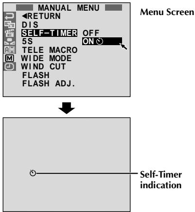
| SELF-TIMER | Refer to “Self-Timer” (║ pg. 32). | ||
| 5S | OFF | Refer to “5-Second Recording” (║ pg. 33). | |
| 5S | |||
| ANIM. | Allows you to record a few frames only. By using an inanimate object and changing its position between shots, you can record the subject as though it is moving (║ pg. 33). | ||
| TELE-MACRO | OFF | Usually the distance to a subject where the lens is in focus depends on the zoom magnification. Unless there is a distance more than 1m to the subject, the lens is out of focus at the maximum telephoto setting. When set to “ON”, you can shoot a subject as large as possible at a distance of approx. 60 cm. ·Depending on the zoom position, the lens may go out of focus. | |
| ON | |||
| WIDE-MODE | OFF | Records with no change in the screen ratio. For playback on a TV with a normal screen ratio. | |
| CINEMA | Inserts black bands at the top and bottom of the screen. During playback on wide-screen TVs, the black bands at the top and bottom of the screen are cut and the screen ratio becomes 16:9. □ appears. When using this mode, refer to your wide-screen TV's instruction manual. During playback/recording on 4:3 TVs/LCD monitor/viewfinder, black bands are inserted at the top and bottom of the screen and the image appears like a letterboxed 16:9 movie. ·“CINEMA” mode is effective only when the MODE Dial is set to “VIDEO” or “PS”. | ||
| SQUEEZE | For playback on TVs with an aspect ratio of 16:9. Naturally expands the image to fit the screen without distortion. ▼ appears. When using this mode, refer to your wide-screen TV's instruction manual. During playback/recording on 4:3 TVs/LCD monitor/viewfinder, the image is elongated vertically. ·“SQUEEZE” mode is effective only when the MODE Dial is set to “VIDEO” or “PS”. | ||
| PS-WIDE | “SW” appears. The zoom range is extended beyond the maximum optical zoom wide angle range. This mode's wide angle setting is equivalent to using a 0.7X wide conversion lens. Zooming is possible from 0.7X to 10X. This mode is suitable for shooting in a small room. ·“PS-WIDE” mode is effective only when the MODE Dial is set to “PS”. | ||
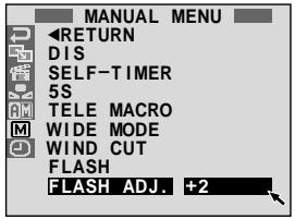
| G MANUAL MENU | WIND CUT | OFF | Disengages the function which cuts down on noise created by wind. |
| ON | Helps cut down on noise created by wind. " " appears. The quality of the sound will change. This is normal. | ||
| FLASH | Refer to "Snapshot Flash" (☐ pg. 30). | ||
| FLASH ADJ. | Refer to "Flash Brightness Adjustment" (☐ pg. 31). | ||
| DISPLAY MENU | ON SCREEN | LCD | Keeps the camcorder's display (except the date, time and time code) from appearing on the connected TV screen. |
| LCD/TV | Makes the camcorder's display appear on screen when the camcorder is connected to a TV. | ||
| SIMPLE | Keeps the indications (except the tape running indicator, warnings, date, time, time code, etc.) from appearing in the camcorder. Also keeps the camcorder's display (except the date, time and time code) from appearing on the connected TV screen. | ||
| DATE/ TIME | AUTO | Displays the date/time for approx. 5 seconds in the following cases: ·When the POWER Switch is set from "OFF" to "CAMERA" or "PLAY/PC". ·When playback starts. The camcorder displays the date/time when scenes are recorded. ·When the date is changed during playback. | |
| OFF | The date/time does not appear. | ||
| ON | The date/time is always displayed. | ||
| TIME CODE | OFF | Time code is not displayed. | |
| ON | Time code is displayed on the camcorder and on the connected TV. Frame numbers are not displayed during recording. | ||
| CLOCK ADJ. | Allows you to set the current date and time (☐ pg. 9). | ||
Factory-preset
NOTES:
- The "MANUAL MENU" settings are effective only when the Operation Switch is set to "M".
- "DISPLAY MENU" functions which are set when the POWER Switch is set to "CAMERA" are also applied when the POWER Switch is set to "PLAY/PC" (13 pg. 41). "CLOCK ADJ." only appears when the POWER Switch is set to "CAMERA".
- The "DISPLAY MENU" settings are effective even when the Operation Switch is set to "A".
- The "ON SCREEN" setting can also be changed by pressing the DISPLAY Button on the remote control (provided) (3) pg. 57, 60, 71).
MENU Wheel
Display
Menu Screen
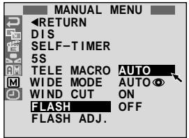
Snapshot Flash
The flash can be used when a snapshot is taken in Record-Standby (pg. 18, 19).
- In Full Auto mode, the flash automatically fires if it is dark ( appears).
- In Manual mode, you can select the "FLASH" setting as follows:
AUTO : Fires automatically if it is dark ( appears).
AUTO : Fires automatically if it is dark ( appears) and reduces the Red-Eye effect in the subject's eyes.
ON : Always fires.
OFF : Will not fire.
Perform the procedure below.
1 Set the Operation Switch to "M" and set the POWER Switch to "CAMERA" while pressing down the Lock Button located on the switch, then pull out the viewfinder or open the LCD monitor fully.
Press the MENU wheel. The Menu Screen appears.
3 Rotate the MENU wheel to select "图", and press it. "MANUAL MENU" appears.
4 Rotate the MENU wheel to select "FLASH", and press it. The Sub Menu appears.
5 Rotate the MENU wheel to select "AUTO", "AUTO ON", "ON" or "OFF", and press it. Rotate the MENU wheel to select "RETURN". Press it twice to close the Menu Screen.
If "AUTO ① Is Selected...
... the Red-Eye reduction indicator lights. Press SNAPSHOT. The flash fires twice. The first flash is for reduction of the human eye's red reflection and the second flash is for the actual recording.
NOTES:
- Do not fire the flash at a person at short range.
- The flash does not fire when the flash is set to "OFF" in the Menu Screen, and also when the battery remaining power is low. Moreover, the flash does not fire when it is set to "AUTO" in the Menu Screen with GAIN UP set to "OFF" (13 pg. 27) and with Programme AE with special effects set to "TWILIGHT" (14 pg. 36).
- When taking several snapshots in succession (Motor Drive Mode), the flash fires only during the first one.
- Although images shot with a flash tend to look whiter than they actually are, to compensate for this the camcorder automatically darkens the picture when using the flash. When shooting a subject at a distance where the flash light cannot reach (over approx. 2m ), push down the flash to prevent the picture from becoming too dark or becoming too tinted.
- The colour tone changes depending on the background lighting conditions, such as under fluorescent or halogen lamps.
- To change the brightness of the flash, "Flash Brightness Adjustment" (13 pg. 31).
- While charging the flash, blinks and the flash will not fire. Although noise may appear, this is not a malfunction and is not recorded. It can take up to 10 seconds to charge the flash.
Display
Menu Screen
Flash Brightness Adjustment
When a snapshot (pg. 18, 19) is taken in the dark the camcorder fires the flash (pg. 30) and adjusts the brightness automatically. You can also adjust the flash brightness manually. When you find that the snapshots you took look too bright or too dark, adjust it manually.
1
Set the Operation Switch to "M" and set the POWER Switch to "CAMERA" while pressing down the Lock Button located on the switch, then pull out the viewfinder or open the LCD monitor fully.
2
Press the MENU wheel. The Menu Screen appears.
3
Rotate the MENU wheel to select "回", and press it. "MANUAL MENU" appears.
4
Rotate the MENU wheel to select "FLASH ADJ.", and press it. The parameter appears.
5
To intensify the flash, rotate the MENU wheel towards "+" . To weaken the flash, rotate it towards " -". Adjustment range: -3 to +3.
6
Press the MENU wheel. Rotate it to select "RETURN" and press it twice to close the Menu Screen.
NOTE:
When you change the subject you are shooting or the shooting location, set it back to ± 0 as described in step 5 and take a snapshot to check the flash brightness. After doing this adjust to your desired brightness.
START/STOP Button
Display
Self-Timer
Once the camcorder is set, the camcorder operator can become part of the scene in a more natural way, adding the final touch to a memorable picture.
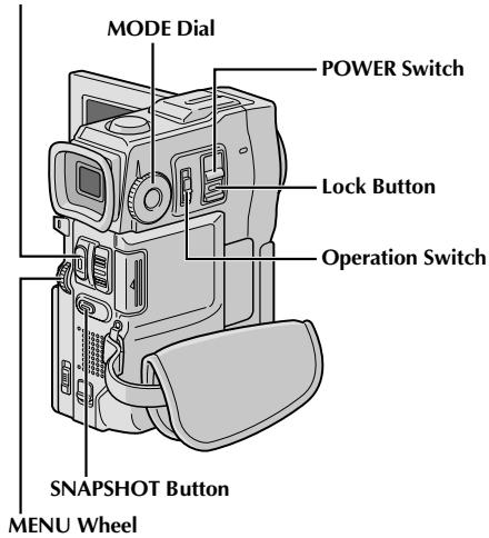
1 Set the Operation Switch to "M" and set the POWER Switch to "CAMERA" while pressing down the Lock Button located on the switch, then pull out the viewfinder or open the LCD monitor fully. - You can tilt the LCD monitor upward to 180^ so that it faces forward and view yourself while selfrecording with the viewfinder pushed back.
Press the MENU wheel. The Menu Screen appears.
2 Rotate the MENU wheel to select "回", and press it.
4 Rotate the MENU wheel to select "SELF-TIMER", and press it. The Sub Menu appears. Rotate the MENU wheel to select "ON", and press it. Selection is complete. Rotate the MENU wheel to select "RETURN", and press it twice to close the Menu Screen.
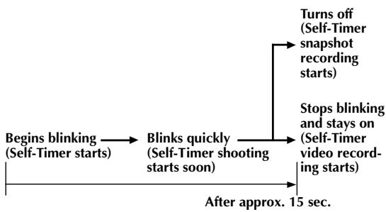
5 To engage the Self-Timer for video recording, press START/STOP. After 15 seconds, the beep sounds and video recording starts. To stop Self-Timer recording, press START/STOP again. The camcorder re-enters Record-Standby mode.
OR
Press SNAPSHOT. After 15 seconds, the beep sounds and snapshot recording starts. After that, the camcorder re-enters Record-Standby mode.
6 To end Self-Timer recording, select "OFF" in step 4 or set the POWER Switch to "OFF" or set the Operation Switch to "A".
NOTE:
If "BEEP/TALLY" is set to "OFF" (13 pg. 27), the beep does not sound and the tally lamp does not light.
START/STOP Button
Display
Menu Screen
5-Second Recording
Record a vacation or an important event in 5-second clips to keep the action moving. This function is available only for video recording.
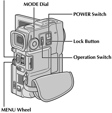
1 Set the POWER Switch to "CAMERA" while pressing down the Lock Button located on the switch and set the MODE Dial to "VIDEO", "PS" or "DUAL", then set the Operation Switch to "M". Pull out the viewfinder fully or open the LCD monitor fully.
Press the MENU wheel. The Menu Screen appears.
3 Rotate the MENU wheel to select "M", and press it. "MANUAL MENU" appears.
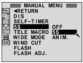
4 Rotate the MENU wheel to select "5S", and press it. The Sub Menu appears.
5 Rotate the MENU wheel to select "5S", and press it. "5S MODE" appears.
6 Press START/STOP. The tally lamp lights and beep sounds to indicate the start of recording, and after 5 seconds the camcorder enters Record-Standby mode.
- Even if you press START/STOP again within 5 seconds after recording starts, Record-Standby mode is not engaged.
To exit the 5S mode, select "OFF" in step 5.
To Take A Snapshot In The 5-Second Recording Mode ... instead of pressing START/STOP in step 6, select the desired Snapshot mode in the Menu Screen, then press SNAPSHOT. The camcorder records a 5-second still (3 pg. 18). When "5S" is set to "ANIM." (3 pg. 28) this function is not available.
NOTE:
When "55" is set to "ANIM." in the Menu Screen the 5-second recording mode is not available. Animation recording of a few frames only is taken instead (13 pg. 28).
Fade/Wipe Effects
These effects let you make pro-style scene transitions. Use them to spice up the transition from one scene to the next. You can also vary transitions from scene to scene.
IMPORTANT:
Some Fade/Wipe Effects cannot be used with certain modes of Programme AE with special effects (13 pg. 36). If an unusable Fade/Wipe Effect is selected, its indicator blinks or goes out.
START/STOP Button
To Deactivate The Selected Effect . . . select "OFF" in step 4.
NOTES:
- You can extend the length of a Fade or Wipe by pressing and holding START/STOP.
- If the power is turned off after a scene is finished recording, the stored point is erased, disabling the Picture Wipe/Dissolve combination. When this happens, the Picture Wipe/Dissolve indicator blinks. Also note that power shuts off automatically if 5 minutes elapse in the Record-Standby mode.
- Picture Wipe/Dissolve cannot be used when the MODE Dial is set to "PS".
- All Fade/Wipe Effects cannot be used when the MODE Dial is set to "DUAL".
The sound at the end of the last recorded scene is not stored.
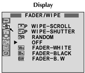
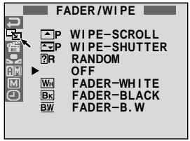
FADE/WIPE SELECTION (WH, Bk, BW, □, □, W, □, and R)
Fade or Wipe works when video recording is started or when you stop recording.
1 Set the POWER Switch to "CAMERA" while pressing down the Lock Button located on the switch and the MODE Dial to "VIDEO" or "PS", then set the Operation Switch to "M". Pull out the viewfinder fully or open the LCD monitor fully.
Press the MENU wheel. The Menu Screen appears.
Rotate the MENU wheel to select "G", then press it.
4 Rotate the MENU wheel to select the desired function, then press it. Selection is complete.
- The FADER/WIPE Menu disappears and the effect is reserved. The indicator representing the selected effect appears.
Press START/STOP to activate the Fade-in/out or Wipe-in/out.
PICTURE WIPE OR DISSOLVE SELECTION (P, P, P, P, P, P and P)
The Picture Wipe or Dissolve works when video recording is started.
1 Follow steps 1 through 4 above.
Engage the Record-Standby mode.
If you select Picture Wipe/Dissolve during recording . . .
... press START/STOP when one scene is finished. The point at which the scene ended is stored in memory.
If you select Picture Wipe/Dissolve during Record-Standby mode . . .
... press START/STOP to start recording and press it again when one scene is finished. The point at which the scene ended is stored in memory.
If you select Picture Wipe/Dissolve during Record-Standby mode after performing a Picture Wipe/Dissolve . . .
.... the point at which the scene ended is already stored in memory.
3 If you start recording a new scene within 5 minutes of the end of the previous recording (without having turned the camcorder's power off), the previous scene wipes out, revealing the new scene.
Fader And Wipe Menu
| Menu | Effect |
| WH FADER — WHITE | Fade in or out with a white screen. |
| BK FADER — BLACK | Fade in or out with a black screen. |
| BW FADER — B.W | Fade in to a colour screen from a black and white screen, or fade out from colour to black and white. |
| WIPE — CORNER | Wipe in on a black screen from the upper right to the lower left corner, or wipe out from lower left to upper right, leaving a black screen. |
| WIPE — WINDOW | The scene starts in the centre of a black screen and wipes in toward the corners, or comes in from the corners, gradually wiping out to the centre. |
| WIPE — SLIDE | Wipe in from right to left, or wipe out from left to right. |
| WIPE — DOOR | Wipe in as the two halves of a black screen open to the left and right, revealing the scene, or wipe out and the black screen reappears from left and right to cover the scene. |
| WIPE — SCROLL | The scene wipes in from the bottom to the top of a black screen, or wipes out from top to bottom, leaving a black screen. |
| WIPE — SHUTTER | Wipe in from the centre of a black screen toward the top and bottom, or wipe out from the top and bottom toward the centre leaving a black screen. |
| DISSOLVE | The new scene gradually appears as the old one gradually disappears. |
| WIPE — CORNER | The new scene wipes in over the previous one from the upper right corner to the lower left corner. |
| WIPE — WINDOW | The next scene gradually wipes in from the centre of the screen toward the corners, covering the previous scene. |
| WIPE — SLIDE | The next scene gradually wipes in over the previous one from right to left. |
| WIPE — DOOR | The previous scene wipes out from the centre to the right and left, like a door being pushed open to reveal the next scene. |
| WIPE — SCROLL | The new scene wipes in over the last one from the bottom of the screen to the top. |
| WIPE — SHUTTER | The new scene wipes in over the previous one from the centre toward the top and bottom of the screen. |
| RANDOM | When this function is activated, the camcorder randomly selects the effect used in scene transition (from BW, WH, BK, □, □, □, □, □, □, □, □, □, and □). The Picture Wipe/Dissolve function is not available. |
IMPORTANT:
Some modes of Programme AE with special effects cannot be used with certain Fade/Wipe Effects (13 pg. 35). If an unusable mode is selected, its indicator blinks or goes out.
MENU Wheel
Menu Screen
Programme AE With Special Effects
1
Set the Operation Switch to "M", then set the POWER Switch to "CAMERA" while pressing down the Lock Button located on the switch. Pull out the viewfinder fully or open the LCD monitor fully.
2
Press the MENU wheel. The Menu Screen appears.
3
Rotate the MENU wheel to select "置", then press it.
4
Rotate the MENU wheel to select the desired mode, then press it. Selection is complete.
- The P.AE/EFFECT Menu disappears and the selected mode is activated. The selected mode indicator appears.
To Deactivate The Selected Mode . . .
...select"OFF"in step4.
NOTE:
Programme AE with special effects can be changed during recording or during Record-Standby.

TWILIGHT
Makes evening scenes look more natural. White Balance (F) pg. 39) is initially set to, but can be changed to your desired setting. When Twilight is chosen, the camcorder automatically adjusts the focus from approx. 10m to infinity. From less than 10m , adjust the focus manually. The flash does not fire in this mode.

SEPIA*1
Recorded scenes have a brownish tint like old photos. Combine this with the Cinema mode for a classic look.
B/W MONOTONE\*1
Like classic black and white films, your footage is shot in B/W. Used together with the Cinema mode, it enhances the "classic film" effect.

CLASSIC FILM*2
Gives recorded scenes a strobe effect.

STROBE*2
Your recording looks like a series of consecutive snapshots.

VIDEO ECHO*3
Adds a "ghost" to the subject, giving your recording a "fantasy" feeling. Zoom magnification of over 10X is not available.
SLOW (Slow Shutter)*4
Lights dark subjects or areas even brighter than they would be under good natural lighting. Use "SLOW" only in dark areas.
求1 SLOW 1
Slow Shutter raises light sensitivity to allow shooting in dark environments.
2 SLOW 2
Slow Shutter raises light sensitivity further to allow shooting in even darker environments.
NOTES:
- When using "SLOW", the image takes on a strobe-like effect.
- If the manual focus indicator blinks when "SLOW" is used, adjust focus manually and use a tripod.
SHUTTER (Variable Shutter Speed)
1/50 - The shutter speed is fixed at 1/50th of a second. Black bands that usually appear when shooting a TV screen become narrower.
1/100 – The shutter speed is fixed at 1/100th of a second. The flickering that occurs when shooting under a fluorescent light or mercury-vapour lamp is reduced.
1/250 – This setting allows fast-moving images to be captured one frame at a time, for vivid, stable slow-motion playback. The faster the shutter speed, the darker the picture becomes. Use the shutter function under good lighting conditions.
1 Not available when the MODE Dial is set to "DUAL".
2 Available only when the MODE Dial is set to "VIDEO" or "PS".
3 Available only when the MODE Dial is set to "VIDEO" or "DSC" (VGA STD/VGA FINE only).
4 Available only when the MODE Dial is set to "VIDEO", "PS" or "DSC".
You can download sound data available at our Web Site (see below for URL) and transfer them from your PC to the MultiMediaCard to create more sound effects.
http://www.jvc-victor.co.jp/english/download/d-sound/index.html
- Use the PC card adapter CU-V50U or floppy adapter CU-VFM40U to transfer sound data from a PC to the MultiMediaCard.
- Sound data should be copied into the MultiMediaCard's DCSD¥100JVCGR folder.
- The file names should be in numerical sequence starting from DVC00001.mp3. If you are using the provided MultiMediaCard, file names should be from DVC00013.mp3 since 12 sound effects are pre-stored as DVC00001.mp3 through DVC00012.mp3.
Digital Sound Effects
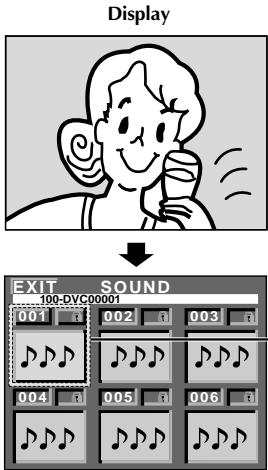
12 sound effects (EXPLOSION, SIREN, LAUGHTER, RACE CAR, DOOR BELL, BUZZER, FANFARE, APPLAUSE, CHEERS, BOING, SCREAM and JEERS) pre-stored in the provided MultiMediaCard can be dubbed onto a tape.
SOUND EFFECT MODE SELECTION
1 Load the provided MultiMediaCard (pg. 12) and a cassette (pg. 10).
2 Set the POWER Switch to "CAMERA" while pressing down the Lock Button located on the switch and set the MODE Dial to "FS", "VIDEO" or "DUAL". Open the LCD monitor fully or pull out the viewfinder fully.
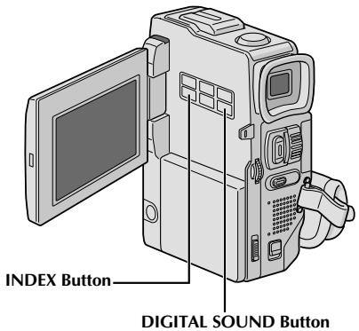
Press INDEX. The SOUND Index Screen appears.
4 Rotate the MENU wheel to select the desired sound effect.
- Pressing DIGITAL SOUND starts playback of the currently selected sound effect so you can check it without recording it onto the tape. Press DIGITAL SOUND again to stop the sound effect playback.
Press the MENU wheel. The selection is complete.
6 Press DIGITAL SOUND during recording. The selected sound effect indication with a “ ” mark appears blinking and the sound effect is recorded onto the tape.
- The sound effect cannot be heard from the speaker during recording. Use a headphone set to hear the sound effect.
To cancel recording the sound effect midway . . .
... press DIGITAL SOUND again. The camcorder stops recording the sound effect and the sound effect indication disappears.
NOTES:
Sound effects can also be used for Audio Dubbing (13 pg. 77).
- Sound effects created on a PC can be transferred to a MultiMediaCard by copying them into the MultiMediaCard's sound folder with the specified file name. For details, refer to the instruction manual of the provided software.
Exposure Control
Manual exposure adjustment is recommended in the following situations:
- When shooting using reverse lighting or when the background is too bright.
- When shooting on a reflective natural background such as at the beach or when skiing.
- When the background is overly dark or the subject light.
1 Set the Operation Switch to "M" and set the POWER Switch to "CAMERA" while pressing down the Lock Button located on the switch, then pull out the viewfinder fully or open the LCD monitor fully.
Press EXPOSURE. "EXP." and the exposure control indicator appear.
3 Rotate the MENU wheel towards "+" to brighten the image, or towards "−" to darken the image. (maximum ±6)
4 Press the MENU wheel. Exposure adjustment is complete. "EXP." goes out.
To Return To Automatic Exposure Control . . .
... press EXPOSURE or set the Operation Switch to "A".
To Brighten The Subject Quickly...
... press BACKLIGHT. 2 is displayed and the subject is brightened. If pressed again, 2 disappears and the brightness returns to the previous level.
- +3 exposure has the same effect as the BACKLIGHT Button.
- Using BACKLIGHT may cause the light around the subject to become too bright and the subject to become white.
- Backlight compensations is also available when the Operation Switch is set to "A".
Iris Lock
Use this function in the following situations:
- When shooting a moving subject.
- When the distance to the subject changes (so its size in the LCD monitor or the viewfinder changes), such as when the subject is backing away.
- When shooting on a reflective natural background such as at the beach or when skiing.
- When shooting objects under a spotlight.
- When zooming.
When the subject is close, keep the iris locked. Even when the subject moves away from you, the image will not darken or brighten.
Before the following steps, perform steps 1 and 2 of "Exposure Control".
Adjust zoom so that the subject fills the LCD monitor or the viewfinder, then press and hold the MENU wheel for over 2 seconds. The exposure control indicator and "L" appear. Press the MENU wheel. "L" changes to "L" and the iris is locked. "EXP." goes out.
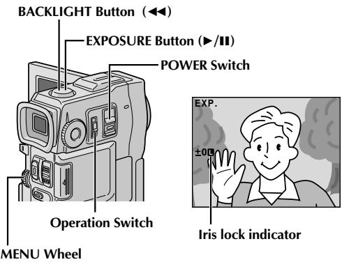
To Return To Automatic Iris Control...
... press EXPOSURE so that the exposure control indicator and "B" disappear. Or, set the Operation Switch to "A".
To Lock The Exposure Control And The Iris . . .
... after step 2, adjust the exposure rotating the MENU wheel. Then lock the iris in step 3. For automatic locking, press EXPOSURE again in step 2. The iris becomes automatic after about 2 seconds.
Iris
Like the pupil of the human eye, it contracts in welllit environments to keep too much light from entering, and dilates in dim environments to allow in more light.
White Balance Adjustment
A term that refers to the correctness of colour reproduction under various lighting. If the white balance is correct, all other colours will be accurately reproduced.
The white balance is usually adjusted automatically. However, more advanced camcorder operators control this function manually to achieve a more professional colour/tint reproduction.
1 Set the Operation Switch to "M" and set the POWER Switch to "CAMERA" while pressing down the Lock Button located on the switch, then pull out the viewfinder fully or open the LCD monitor fully.
Press the MENU wheel. The Menu Screen appears.
3 Rotate the MENU wheel to select " ", then press it. The "W.BALANCE" Menu appears.
4 Rotate the MENU wheel to select "MANUAL", and press it. The Menu Screen disappears and "W.BAL" and the currently selected mode are displayed. Rotate it to select the desired mode.
"MAN." - White balance is set manually.
" - Outdoors on a sunny day.
"-" - Outdoors on a cloudy day.
"-" - A video light or similar type of lighting is used.
Press the MENU wheel. Selection is complete.
To Return To Automatic White Balance . . .
... select "AUTO" in step 4. Or, set the Operation Switch to "A".
NOTE:
White balance cannot be used when Sepia or Monotone (pg. 36) is activated.
Manual White Balance Operation
Perform Manual White Balance when shooting under various types of lighting.
1 Follow steps 1 through 4 of the white balance adjustment, and select "MAN."
2 Hold a sheet of plain white paper in front of the subject. Adjust zoom or position yourself so that the white paper fills the screen.
Press the MENU wheel until begins blinking.
When the setting is completed, stops blinking.
4 Press the MENU wheel. Only the Manual White Balance indicator is displayed.
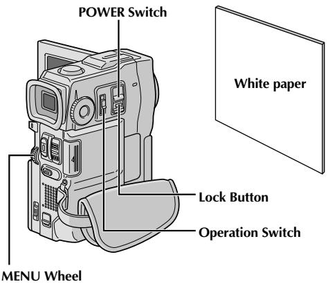
To Change The Tint For Recording . . .
... in step 2, substitute coloured paper for white. The white balance is adjusted based on the colour, changing the tint. Red paper = deeper green; blue paper = orange; yellow paper = deeper purple.
NOTES:
- In step 2, it may be difficult to focus on the white paper. In such a case, adjust focus manually (13 pg. 25).
- A subject can be shot under various types of lighting conditions indoors (natural, fluorescent, candlelight, etc.). Because the colour temperature is different depending on the light source, the subject tint will differ depending on the white balance settings. Use this function for a more natural result.
- Once you adjust white balance manually, the setting is retained even if the power is turned off or the battery removed.
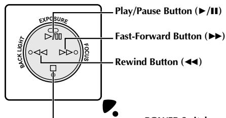
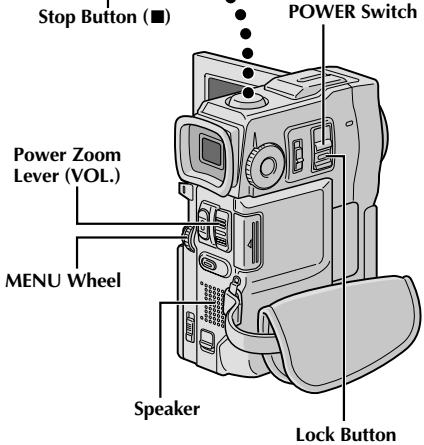
1 Load a tape (pg. 10).
2 Set the POWER Switch to "PLAY/PC" while pressing down the Lock Button located on the switch. To start playback, press /II.
- To stop playback, press ■.
- Press to rewind, or to fast-forward the tape during Stop mode.
To Control The Speaker Volume...
.... slide the Power Zoom Lever (VOL.) towards "+" to turn up the volume, or towards - to turn down the volume.
NOTES:
- If Stop mode continues for 5 minutes when power is supplied from a battery, the camcorder shuts off automatically. To turn on again, set the POWER Switch to "OFF", then to "PLAY/PC".
- The playback picture can be viewed in the LCD monitor, viewfinder or on a connected TV (13 pg. 56).
- You can also view the playback picture on the LCD monitor with it flipped over and pushed against the camera body.
-
LCD monitor/viewfinder indications:
-
When power is supplied from a battery: the " " battery pack remaining power indicator is displayed. When power is supplied through the DC cord: " " does not appear.
-
During Stop mode, none of the indications are displayed.
-
When a cable is connected to the AV OUT connector, the sound is not heard from the speaker.
Still Playback: Pauses during playback.
1) Press /II during playback.
2) To resume normal playback, press /II again.
- If still playback continues for more than about 3 minutes, the camcorder's Stop mode is automatically engaged. After 5 minutes in the Stop mode, the camcorder's power is automatically turned off.
- When /II is pressed, the image may not pause immediately while the camcorder stabilises the still image.
Shuttle Search: Allows high-speed search in either direction.
1) Press for forward or for reverse search during playback.
2) To resume normal playback, press /II.
- During playback, press and hold or . The search continues as long as you hold the button. Once you release it, normal playback resumes.
- A slight mosaic effect appears on screen during Shuttle Search. This is not a malfunction.
Frame-By-Frame Playback: Allows frame-by-frame search.
1) Engage Still Playback.
2) Rotate the MENU wheel towards "+" for forward Frame-By-Frame Playback, or towards "-" for reverse Frame-By-Frame Playback during Still Playback.
To resume normal playback, press /11.
- You can also use the provided remote control for Frame-By-Frame Playback (C) pg. 68).
Slow-Motion Playback, Playback Zoom and Playback Special Effects
Available only with the remote control (provided) ( pg. 68, 69).
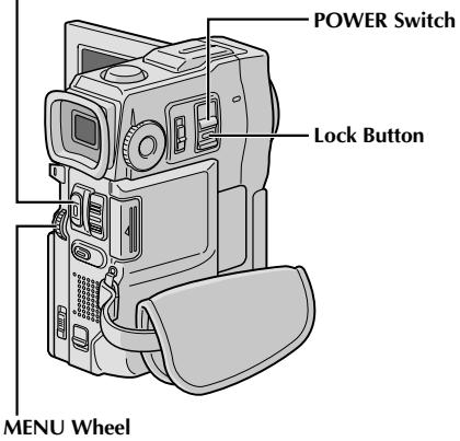
START/STOP Button
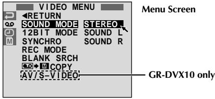
Display
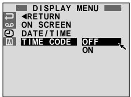
* Each setting is linked with "DISPLAY MENU", which appears when the Operation Switch is set to "M" (13 pg. 29). The parameters are the same as in the description on pg. 29.
NOTES:
- It is also possible to change the ON SCREEN settings by pressing DISPLAY on the remote control (provided).
- "REC MODE" can be set when the Operation Switch is set to "M" (F pg. 11, 27).
- If "ON SCREEN" is set to "SIMPLE", it keeps the camcorder's display (except the date, time and time code) from appearing on the connected TV. It also makes the playback sound mode and tape speed disappear on the camcorder.
Using Menus For Detailed Adjustment
The following procedure applies to all except Synchro Comp (13 pg. 74, 75).
1 Set the POWER Switch to "PLAY/PC" while pressing down the Lock Button located on the switch.
Press the MENU wheel. The Menu Screen appears.
3 Rotate the MENU wheel to select the desired function icon, and press it. The selected function menu appears.
4 Rotate the MENU wheel to select the desired function, and press it to display the Sub Menu.
5 Rotate the MENU wheel to select the desired parameter and press it. Selection is complete.
Rotate the MENU wheel to select "RETURN" and press it twice to close the Menu Screen.
| VIDEO MENU | SOUND MODE | pg. 42. |
| 12BIT MODE | pg. 42. | |
| SYNCHRO | pg. 75. | |
| REC MODE | Allows you to set the video recording mode (SP or LP) depending on your preference (pg. 11). It is recommended you use "REC MODE" in the "VIDEO MENU" when using this camcorder as a recorder during digital dubbing (GR-DVX10 only pg. 61, 63). | |
| BLANK SRCH | Helps find a blank portion of tape when you want to record from the middle of a tape (pg. 43). | |
| COPY | ON: Enables dubbing of images recorded on a tape to a MultiMediaCard (pg. 65). OFF: Enables snapshots to be taken during video playback. | |
| AV/S-VIDEO (GR-DVX10 only) | IN: Enables audio/video signal input from the AV and S-VIDEO connectors (pg. 61). OUT: Enables audio/video signal output to a TV, VCR, etc. via the AV and S-VIDEO connectors (pg. 56, 60). | |
| DISPLAY MENU | ON SCREEN* | Makes the camcorder's indications appear/disappear from the connected TV screen. |
| DATE/TIME* | Makes the date/time appear/disappear on the camcorder. | |
| TIME CODE* | Makes the time code appear/disappear on the camcorder. |
Playback Sound
During playback, the camcorder detects the sound mode in which the recording was made, and plays the sound back. Select the type of sound to accompany your playback picture. According to the menu access explanation on pg. 41, select "SOUND MODE" or "12BIT MODE" from the Menu Screen and set it to the desired parameter.
| SOUND MODE | STEREO | Sound is output on both “L” and “R” channels in stereo. |
| SOUND L | Sound from the “L” channel is output in stereo. | |
| SOUND R | Sound from the “R” channel is output in stereo. | |
| 12BIT MODE | SOUND 1 | Original sound is output on both “L” and “R” channels in stereo. |
| SOUND 2 | Dubbed sound is output on both “L” and “R” channels in stereo. | |
| MIX | Original and dubbed sounds are combined and output in stereo on both “L” and “R” channels in stereo. |
Factory-preset
NOTES:
- The "SOUND MODE" setting is available for both 12-bit and 16-bit sound. (In previous models' functions, "12-bit" is called "32 kHz" and "16-bit" is called "48 kHz".)
- The camcorder cannot detect the sound mode in which the recording was made during fast-forward or rewind. During playback the sound mode is displayed in the upper left corner.
Display
ON SCREEN setting:
For playback sound, tape speed and tape running.
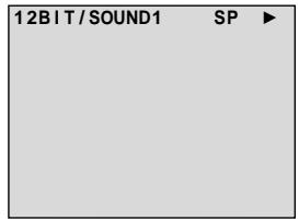
DATE/TIME setting:
For date/time.

TIME CODE setting:
For time code.
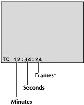
*25 frames = 1 second
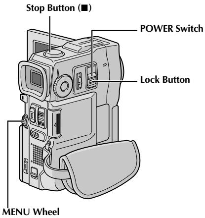
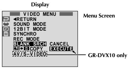

Blank Search
Helps you find where you should start recording in the middle of a tape to avoid time code interruption (pg. 21).
1 Load a tape (FF pg. 10) and set the POWER Switch to "PLAY/PC" while pressing down the Lock Button located on the switch.
Press the MENU wheel. The Menu Screen appears.
3 Rotate the MENU wheel to select "CO", then press it. "VIDEO MENU" appears.
4 Rotate the MENU wheel to select "BLANK SRCH", then press it. The Sub Menu appears.
Rotate the MENU wheel to select "EXECUTE", then press it.
- "BLANK SEARCH" appears blinking and the camcorder automatically starts reverse or forward shuttle search, then stops at the spot which is about 3 seconds of tape before the beginning of the detected blank portion.
To cancel Blank Search midway . . .
... press ■.
NOTES:
- In step 5, if the current position is at a blank portion the camcorder searches in the reverse direction, and if the current position is at a recorded portion the camcorder searches in the forward direction.
- Blank Search does not work if "HEAD CLEANING REQUIRED. USE CLEANING CASSETTE" has appeared with the tape.
- If the beginning or end of the tape is reached during Blank Search, the camcorder stops automatically.
- A blank portion which is shorter than 5 seconds of tape cannot be detected.
- The detected blank portion may be located between recorded scenes. Before you start recording, make sure there is no recorded scene after the blank portion.
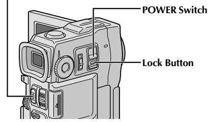
START/STOP Button
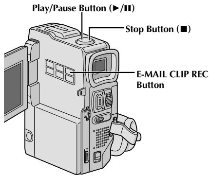

Display

After approx. 20 seconds or when START/STOP is pressed
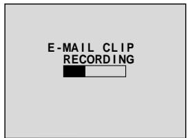

Storing is complete
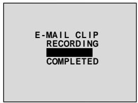
Playback Screen
E-Mail Clip Recording
You can make video clips from recorded video footage and store them in a MultiMediaCard as files which can be conveniently sent via e-mail.
1
Load a MultiMediaCard (pg. 12) and cassette (pg. 10). Set the POWER Switch to "PLAY/PC" while pressing down the Lock Button located on the switch.
2
Press / to start video playback.
3
Press E-MAIL CLIP REC. "E-MAIL CLIP STAND-BY" appears and the camcorder enters the E-Mail Clip Record-Standby mode.
4
Press START/STOP. "E-MAIL CLIP RECORDING" appears.
- The camcorder stops E-Mail Clip Recording automatically after approx. 20 seconds, then starts storing the recorded video data in the MultiMediaCard which takes approx. 100 seconds additionally. "COMPLETED" appears when it is complete.
To cancel E-Mail Clip Recording . . .
... after step 3, press E-MAIL CLIP REC again or press to stop video playback.
To view video clips stored in a MultiMediaCard . . .
... the video clip selected in the E-CLIP Index Screen (13 pg. 47, Index Playback) can be viewed in the LCD monitor or viewfinder; video clips cannot be displayed on a connected TV.
NOTES:
- Playback operation cannot be performed during E-Mail Clip Recording.
- If you press START/STOP while E-Mail Clip Recording is in progress, only the portion which is recorded before START/STOP is pressed will be stored in the MultiMediaCard.
- Also, if the end of the tape is reached during E-Mail Clip Recording, that portion will be automatically stored in the MultiMediaCard.
- If the end of the tape is reached in step 3, the E-Mail Clip Record-Standby mode will be automatically cancelled.
Refer to the instruction manual of the provided software, CardNavigator, Video Player and JVC Video Decoder. - Video noise may appear while viewing video clips in the LCD monitor or viewfinder, however, this noise is not present in the actual video clips stored in the MultiMediaCard.
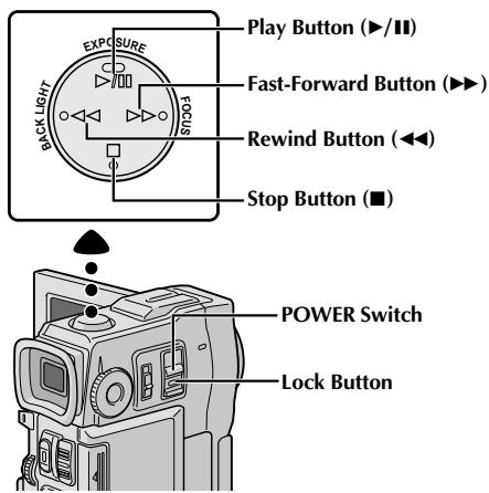
[For Normal Playback]
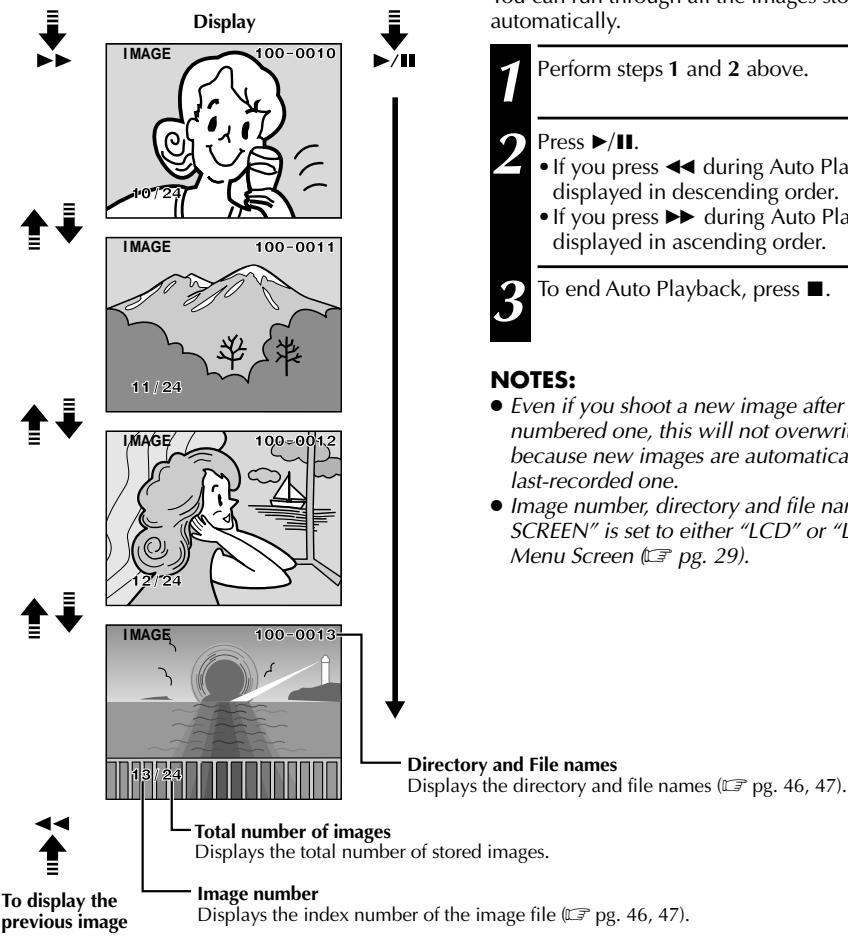
To display the next image
[For Auto Playback]
Normal Playback
Images shot with the camcorder are automatically numbered, then stored in numerical order in the MultiMediaCard. You can view the stored images, one at a time, much like flipping through a photo album.
1 Load a MultiMediaCard (pg. 12).
2 Set the POWER Switch to " M E M O R Y while pressing down the Lock Button located on the switch. Open the LCD monitor fully or pull out the viewfinder fully. A stored image is displayed.
Press to display the next image. Press to display the previous image.
Auto Playback
You can run through all the images stored in memory automatically.
1 Perform steps 1 and 2 above.
Press /II.
If you press during Auto Playback, images are displayed in descending order.
- If you press during Auto Playback, images are displayed in ascending order.
To end Auto Playback, press ■.
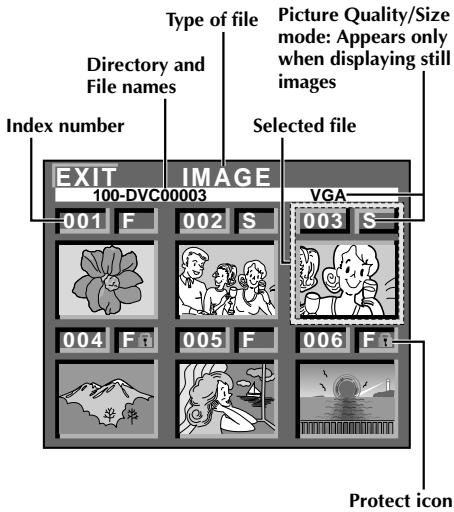
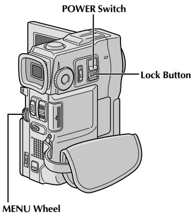
Index Screen
The files you stored can be displayed together with their index information. Convenient for checking files stored beforehand, the Index Screen also shows the Picture Quality/Size mode, directory and file names as well as which files are protected against accidental erasure.
100-DVC00003: Directory and File names
Shows that the selected file is in a directory called "100" and its file name is "DVC00003".
Each time shooting takes place, a file name is made using a number which is larger by one than the largest number of the file names which are in use. If the file name reaches DVC09999, a new directory will be made and the file name will start again from DVC00001.
In the playback screen (pg. 45), the directory and only the last four digits of the file name are displayed.
001: Index number
Index numbers are marked from 001. For example, when 10 files are stored (index number: 001 to 010), if three files with index numbers 002, 004 and 006 are deleted from memory, the remaining files are automatically moved up to fill any gaps in the numerical sequence. Therefore, the number of remaining files is 7, and the new index numbers range from 001 to 007.
F/S/XGA/VGA: Picture Quality/Size mode
Displays the Picture Quality/Size mode of the stored image. There are 4 modes available: XGA FINE, XGA STD, VGA FINE and VGA STD (in order of quality) (13).
: Protect icon
When a file is protected against its accidental erasure, a padlock mark appears next to the index number, and that file cannot be deleted.
Selected File
A file is framed in green when it is selected. Rotate the MENU wheel to move the green frame to the desired file.
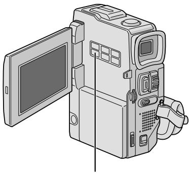
INDEX Button

Display
Playback Screen
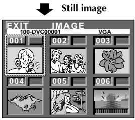

Video clip
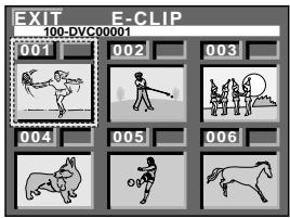

Sound effect
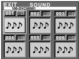
Index Playback
You can view or listen to the files (still images, video clips, or sound effects) stored in memory six at a time. Use this mode when looking for a file you wish to view or hear.
1 Perform steps 1 and 2 of "Normal Playback" on pg. 45.
To access the Index Screen, press INDEX once.
If you press INDEX twice...
the Index Screen for E-Mail Clip Rec (pg. 44) appears, if a video clip has been stored. (If there is no video clip, this will be skipped.)
If you press INDEX three times . . .
the Index Screen for Digital Sound Effect (pg. 37) appears. (If there is no sound effect, the display will return to the still image Index Screen.)
3 Rotate the MENU wheel to move the green frame to the desired file and press it. The file selected in the Index Screen is displayed or played back.

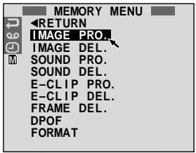
Display
Menu Screen
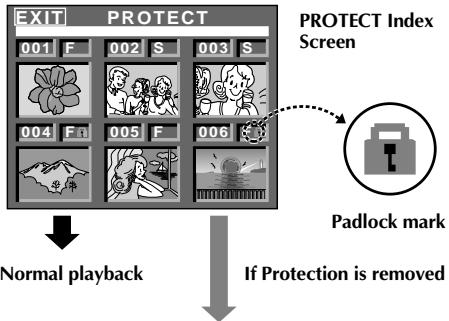
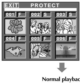
Protecting Files
The Protect mode helps prevent the accidental erasure of files. When a padlock mark is displayed next to the index number, that file cannot be deleted.
1 Set the POWER Switch to " " while pressing down the Lock Button located on the switch. Open the LCD monitor fully or pull out the viewfinder fully. A stored file is displayed.
2 Press the MENU wheel. The Menu Screen appears. Rotate it to select "M" and press it. "MEMORY MENU" appears.
3 By rotating the MENU wheel... .. select "IMAGE PRO." to access the PROTECT Index Screen. .. select "E-CLIP PRO." to access the E-Clip Rec PROTECT Index Screen.. .. select "SOUND PRO." to access the Sound Effect PROTECT Index Screen. Then press the MENU wheel.
TO PROTECT A FILE
Before doing the following, perform steps 1 through 3 above.
4 Rotate the MENU wheel to move the green frame to the desired file and press it. A " " padlock mark appears on the selected file. Repeat this procedure for all files you do not wish to delete by accident.
5 Rotate the MENU wheel upward to select "EXIT" and press it. The normal playback screen appears.
NOTE:
When the memory is initialised or corrupted, even protected files are deleted. If you do not want to lose important files, transfer them to a PC and save them.
TO REMOVE PROTECTION
Before doing the following, perform steps 1 through 3 above.
4 Rotate the MENU wheel to move the green frame to the desired file and press it. The "窗口" padlock mark located above the file disappears and the file is no longer protected. Repeat this procedure for all files from which you wish to remove protection.
5 Rotate the MENU wheel upward to select "EXIT" and press it. The normal playback screen appears.

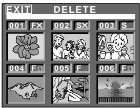
Display
DELETE Index Screen
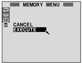
Deletion Confirmation Screen
CAUTION:
Do not remove the MultiMediaCard or perform any other operation (such as turning off the camcorder) during deletion. Also, be sure to use the provided AC Power Adapter/Charger, as the MultiMediaCard may be corrupted if the battery becomes exhausted during deletion. If the MultiMediaCard becomes corrupted, initialise it. (13 pg. 50)
Deleting Files
Previously stored files can be deleted either one at a time or all at once.
1 Set the POWER Switch to " E M O R Y " while pressing down the Lock Button located on the switch. Open the LCD monitor fully or pull out the viewfinder fully. A stored file is displayed.
2 Press the MENU wheel. The Menu Screen appears. Rotate it to select "M" and press it. "MEMORY MENU" appears.
3 By rotating the MENU wheel... ... select "IMAGE DEL." to delete images. ... select "E-CLIP DEL." to delete E-clip recording files. ... select "SOUND DEL." to delete sound effects. Then press the MENU wheel. The Sub Menu appears.
TO SELECT A FILE BY BROWSING FILES STORED IN MEMORY
Before doing the following, perform steps 1 through 3 above.
4 Rotate the MENU wheel to select "SELECT" and press it. The DELETE Index Screen appears.
5 Rotate the MENU wheel to move the green frame to the desired file that you wish to delete and press it. An "X" appears above the selected file. Repeat this procedure for all files that you wish to delete. To deselect a file, press the MENU wheel again. The "X" disappears.
6 Rotate the MENU wheel upward to select "EXIT" and press it. The Deletion Confirmation Screen appears.
7 Rotate the MENU wheel to select "EXECUTE" and press it. The selected files are deleted and the normal playback screen appears. To cancel deletion, rotate the MENU wheel to select "CANCEL" and press it.
TO DELETE ALL FILES
Before doing the following, perform steps 1 through 3 above.
4 Rotate the MENU wheel to select "ALL" and press it. The Deletion Confirmation Screen appears.
5 Rotate the MENU wheel to select "EXECUTE" and press it. All the files are deleted. To cancel deletion, rotate the MENU wheel to select "CANCEL" and press it.
NOTES:
- Protected files (13 pg. 48) cannot be deleted with the above operation. To delete them, remove protection first.
- Once files are deleted, they cannot be restored. Check files before deleting.

Display
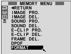
Menu Screen

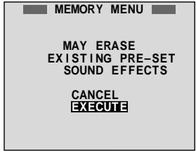
Confirmation Screen
Initialising A MultiMediaCard
You can initialise a MultiMediaCard anytime. After initialising, all images and data stored in the MultiMediaCard, including those which have been protected, are cleared.
1 Set the POWER Switch to "MEMORY" while pressing down the Lock Button located on the switch. Open the LCD monitor fully or pull out the viewfinder fully.
Press the MENU wheel. The Menu Screen appears.
3 Rotate the MENU wheel to select "M" and press it. "MEMORY MENU" appears.
4 Rotate the MENU wheel to select "FORMAT" and press it. The Confirmation Screen appears.
5 Rotate the MENU wheel to select "EXECUTE" and press it. The MultiMediaCard is initialised. When initialisation is finished, "NO STORED DATA" appears.
- To cancel initialisation, rotate the MENU wheel to select "CANCEL" and press it.
CAUTION:
Do not perform any other operation (such as turning off the camcorder) during initialisation. Also, be sure to use the provided AC Power Adapter/Charger, as the MultiMediaCard may be corrupted if the battery becomes exhausted during initialisation. If MultiMediaCard becomes corrupted initialise it.
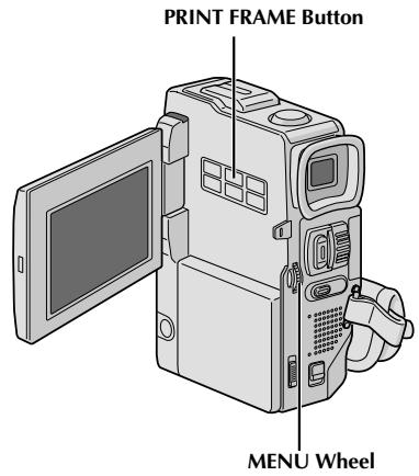
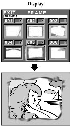
Print Frame Index Screen
Superimposing A Print Frame
A selection of print frames are stored in the camcorder. A frame can be superimposed over a still image.
1 Play back an image stored in the MultiMediaCard.
Press PRINT FRAME. The Print Frame Index Screen appears.
3 Rotate the MENU wheel to move the green frame to the desired print frame and press it. Selection is complete. The selected print frame is superimposed over the still image.
To Make The Print FrameDisappear . . . .press PRINT FRAME.
NOTES:
- A print frame created on a PC can be transferred to a MultiMediaCard using the provided software. Transferred print frames are displayed from print frame index number 007, and they can be used together with the print frames in the camcorder's memory. For details on creating/transferring print frames, refer to the software instructions.
- Depending on the images you play back, the print frame outline may become grainy or vague.


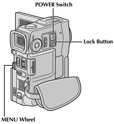
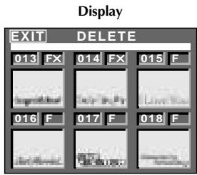
DELETE Index Screen
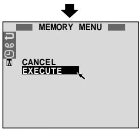
Deletion Confirmation Screen
CAUTION:
Do not remove the MultiMediaCard or perform any other operation (such as turning off the camcorder) during deletion. Also, be sure to use the provided AC Power Adapter/Charger, as the MultiMediaCard may be corrupted if the battery becomes exhausted during deletion. If the MultiMediaCard becomes corrupted, initialise it. (13 pg. 50)
Print Frame Deletion
A print frame created on a PC can be transferred to a MultiMediaCard using the provided software. Print frames that have been transferred to a MultiMediaCard can be deleted when they are no longer needed.
There are 2 ways of deleting previously created print frames: by browsing through print frames individually or by deleting them all at once.
TO SELECT A PRINT FRAME BY BROWSING PRINT FRAMES STORED IN MEMORY
1 Set the POWER Switch to "MEMORY" while pressing down the Lock Button located on the switch.
Press the MENU wheel. The Menu Screen appears.
3 Rotate the MENU wheel to select "M" and press it. "MEMORY MENU" appears.
4 Rotate the MENU wheel to select "FRAME DEL." and press it. The Sub Menu appears.
Rotate the MENU wheel to select "SELECT" and press it. The DELETE Index Screen appears.
6 Rotate the MENU wheel to move the green frame to the desired print frame that you wish to delete and press it. An "X" appears above the selected print frame.
Repeat this procedure for all print frames that you wish to delete.
To deselect a print frame, press the MENU wheel again. The "X" disappears.
7 Rotate the MENU wheel upward to select "EXIT" and press it. The Deletion Confirmation Screen appears.
8 Rotate the MENU wheel to select "EXECUTE" and press it. The selected print frames are deleted and the normal playback screen appears.
- To cancel deletion, rotate the MENU wheel to select "CANCEL" and press it.
NOTES:
- If print frames created on a PC have not been transferred to a MultiMediaCard, it is not possible to delete them using these steps.
- The print frames in the camcorder's memory cannot be deleted.

TO DELETE ALL PRINT FRAMES
1 Perform steps 1 through 4 on pag. 52.
2 Rotate the MENU wheel to select "ALL" and press it. The Deletion Confirmation Screen appears.
3 Rotate the MENU wheel to select "EXECUTE" and press it. All the print frames are deleted.
- To cancel deletion, rotate the MENU wheel to select "CANCEL" and press it.
Display
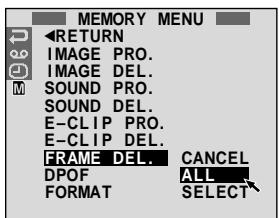
Menu Screen
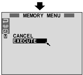
Deletion
Confirmation
Screen

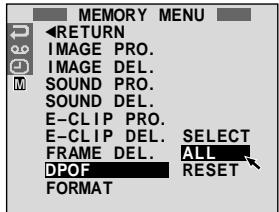
Display
Menu Screen
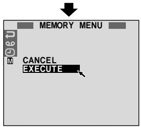
Confirmation Screen
Setting Print Information (DPOF Setting)
This camcorder is compatible with the DPOF (Digital Print Order Format) standard in order to support future systems such as automatic printing, which records information about the still images you wish to print (such as the number of prints to make). There are 2 print information settings available: "To print all still images (one print for each)" explained below and "To print by selecting still images and no. of prints" (13 pg. 55).
TO PRINT ALL STILL IMAGES (ONE PRINT FOR EACH)
1 Set the POWER Switch to "MEMORY" while pressing down the Lock Button located on the switch. Open the LCD monitor fully or pull out the viewfinder fully.
Press the MENU wheel. The Menu Screen appears.
3 Rotate the MENU wheel to select "M" and press it. "MEMORY MENU" appears.
4 Rotate the MENU wheel to select "DPOF" and press it. The Sub Menu appears.
5 Rotate the MENU wheel to select "ALL" and press it. Selection is complete. The Confirmation Screen appears.
Rotate the MENU wheel to select "EXECUTE" and press it. The normal playback screen appears.
- To cancel selection, rotate the MENU wheel to select "CANCEL" and press it.
To Reset The Setting...
... select "RESET" in step 5. The setting is reset to 0 for all still images.

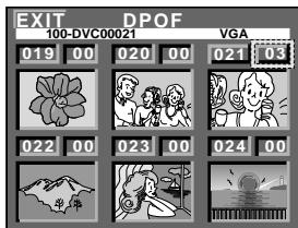
Display
DPOF Screen
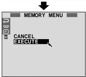
Confirmation Screen
TO PRINT BY SELECTING STILL IMAGES AND NO. OF PRINTS
1 Perform steps 1 through 4 on pg. 54.
2 Rotate the MENU wheel to deselect "SELECT" and press it. Selection is complete. The DPOF Screen appears.
3 Rotate the MENU wheel to move the green frame to the image you wish to print and press it.
4 Select the number of prints by rotating the MENU wheel towards ^ 十 to increase the number, or towards - to decrease the number and press it. Repeat steps 3 and 4 for the desired number of prints. The number of prints can be set up to 15. To correct the number of prints, select the image again and change the number.
5 Rotate the MENU wheel upward to select "EXIT" and press it. Selection is complete. The Confirmation Screen appears.
6 Rotate the MENU wheel to select "EXECUTE" and press it. The normal playback screen appears. To cancel selection, rotate the MENU wheel to select "CANCEL" and press it.
To Reset The No. Of Prints...
... select "RESET" in step 5 on pg. 54. The number of prints is reset to 0 for all still images.
CAUTION:
While performing the above, never disconnect power, as this may cause the memory to be corrupted. For safety, all buttons including the POWER Switch are disabled in step 5.
NOTES:
- If you load a MultiMediaCard already set as shown above in a printer compatible with DPOF, it will make prints of the selected still images automatically.
- To print images recorded on a tape, first dub them to a MultiMediaCard (13 pg. 65).
These are some basic types of connections. When making the connections, refer also to your VCR and TV instruction manuals.
A. Connection to a TV or VCR equipped with a SCART connector compatible only with regular video signal
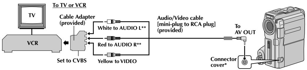
- When connecting the cables, open this cover.
**The Audio cable is not required for watching still images with the POWER Switch set to "MEMORY PLAY".
B. Connection to a TV or VCR equipped with a SCART connector compatible with Y/C signal
Docking Station Attachment
Align the direction stud and screw on the Docking Station with the stud hole and tripod mounting socket on the camcorder.
Tighten the screw.
- When removing the camcorder, loosen the screw and detach the camcorder.
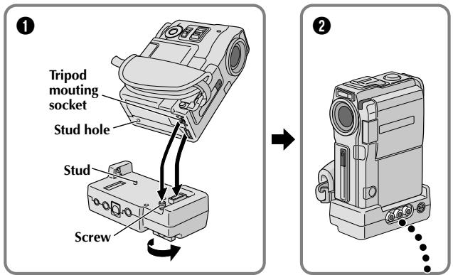
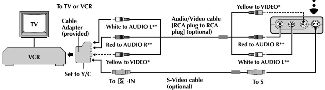
Connect when an S-Video cable is not used.
*The Audio cable is not required for watching still images with the POWER Switch set to “MEMORY PLAY”.
C. Connection to a TV or VCR equipped with an S-VIDEO IN and/or A/V input (RCA type) connectors
- The Audio cable is not required for watching still images with the POWER Switch set to “ PLAY ”.
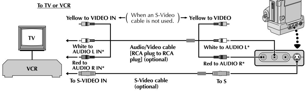
| 1 | Make sure all units are turned off. |
| 2 | Connect the camcorder to a TV or VCR as shown in the illustration (电视、pg. 56, 57). If using a VCR... go to step 3. If not... go to step 4. |
| 3 | Connect the VCR output to the TV input, referring to your VCR's instruction manual. |
| 4 | Turn on the camcorder, the VCR and the TV. |
| 5 | Set the VCR to its AUX input mode, and set the TV to its VIDEO mode. |
To choose whether or not the following displays appear on the connected TV...
- Date/Time ... set "DATE/TIME" to "AUTO", "ON" or "OFF" in the Menu Screen (41).
- Time Code .... set "TIME CODE" to "ON" or "OFF" in the Menu Screen (13 pg. 41).
- Playback Sound Mode, Tape Speed And Tape Running Displays for video playback Or Directory/File Names and Image Number/Total Number of Images for D.S.C. Playback .... set "ON SCREEN" to "LCD" or "SIMPLE" in the Menu Screen (F pg. 41). Or, press DISPLAY on the remote control.
NOTES:
- It is recommended to use the AC Power Adapter/ Charger as the power supply instead of the battery pack (F pg. 7).
- When connecting the cables, make sure to connect the ends with a core filter to the camcorder. The core filter reduces interference.
- To monitor the picture and sound from the camcorder without inserting a tape or MultiMediaCard, set the camcorder's POWER Switch to "CAMERA", then set your TV to the appropriate input mode.
Make sure you adjust the TV sound volume to its minimum level to avoid a sudden burst of sound when the camcorder is turned on. - If you have a TV or speakers that are not specially shielded, do not place the speakers adjacent to the TV as interference will occur in the camcorder playback picture.
- While the Audio/Video cable is connected to the AV OUT connector, sound cannot be heard from the speaker.
- Set the video out select switch of the cable adapter as required:
Y/C : When connecting to a TV or VCR which accepts Y/C signals and uses an S-Video cable.
CVBS : When connecting to a TV or VCR which does not accept Y/C signals and uses an audio/video cable.
PC with DV
connector-equipped capture board


PC
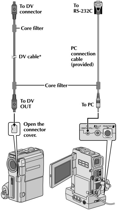
* Use the DV cable provided with the capture board.
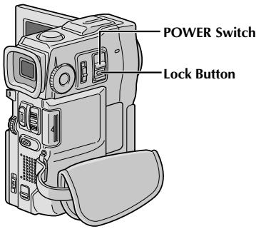
Connection To A Personal Computer
This camcorder can transfer still images to a PC by using the provided software when connected as shown in the illustration. It is also possible to transfer still images to a PC with a DV connector-equipped capture board installed.
1 Make sure the camcorder and PC are turned off.
2 Connect the camcorder or Docking Station to your PC using the appropriate cable as shown in the illustration.
- To attach the camcorder to Docking Station, refer to "Docking Station Attachment" on pg. 56.
3 Turn the camcorder's POWER Switch to "PLAY/PC" while pressing down the Lock Button located on the switch and turn on the PC.
NOTES:
- It is recommended to use the AC Power Adapter/ Charger as the power supply instead of the battery pack (13 pg. 7).
- Never connect the PC connection cable and the DV cable simultaneously to the camcorder. Connect only the cable you wish to use to the camcorder.
The date/time information cannot be captured into the PC.
Refer to the instruction manuals of the provided Software. - Also refer to the manufacturer's instruction manual for the DV connector-equipped capture board.
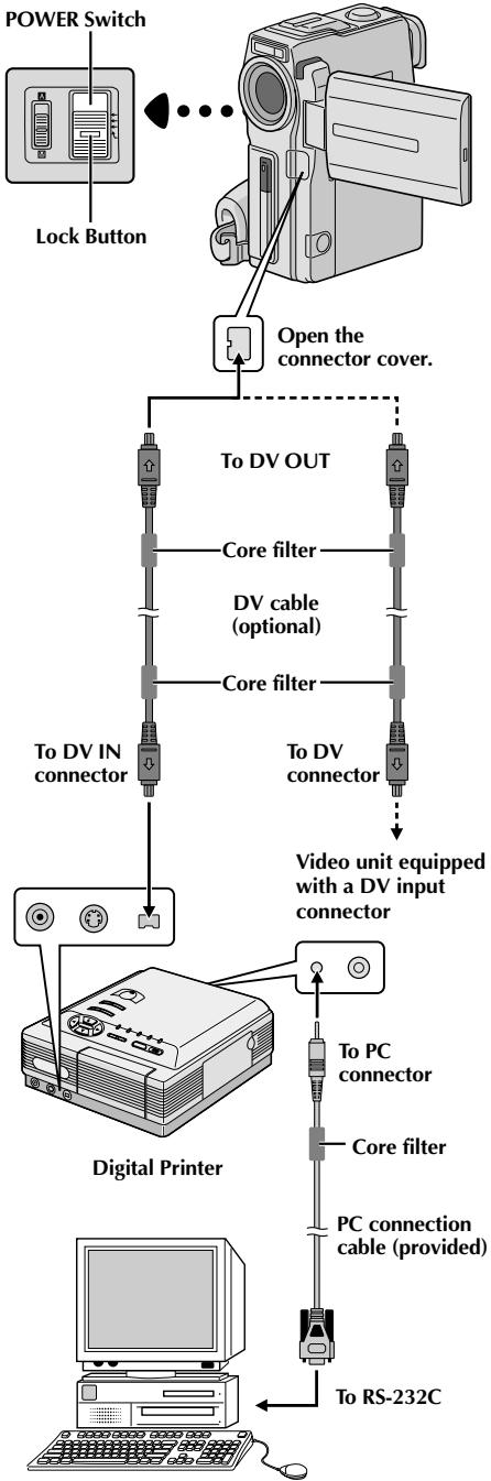
PC
Connection To A Video Unit Equipped With A DV Connector
Connection to the GV-DT3 Digital Printer (optional) allows you to print out images or transfer them to a PC. It is also possible to copy recorded scenes from the camcorder onto another video unit equipped with a DV connector. This function is called Digital Dubbing (CP pg. 62), which offers virtually no image or sound deterioration.
1 Make sure all units are turned off.
2 Make connections to the device you want to connect to using a DV cable, as shown in the illustration.
3 If necessary, connect the PC connection cable (provided) to the printer's PC connector and the PC's RS-232C connector.
4 Turn the camcorder's POWER Switch to "PLAY/PC" while pressing down the Lock Button located on the switch and turn on the other units.
NOTES:
- It is recommended to use the AC Power Adapter/ Charger as the power supply instead of the battery pack (13 pg. 7).
- For Digital Dubbing, this camcorder can be connected only to one device at a time. The GR-DVX10 can be used as both a player and a recorder. The GR-DVX9 can be used only as a player (F pg. 62, 63).
- If Still Playback, Slow-Motion Playback, Fast-Forward or Rewind is attempted with the camcorder connected to a video unit via the DV connector, the image will take on an effect similar to a coloured mosaic pattern or it will become black.
- Also refer to the instruction manuals of the connected units.
- When using a DV cable, be sure to use the optional JVC VC-VDV204U DV cable.
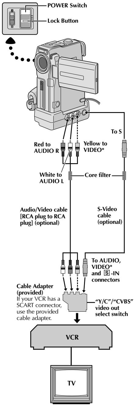
* Connect when an S-Video cable is not used.
Dubbing To A VCR
[To use this camcorder as a player]
1 Following the illustration, connect the camcorder and the VCR. Also refer to pg. 56 and 57.
2 Set the camcorder's POWER Switch to "PLAY/PC" while pressing down the Lock Button located on the switch, turn on the VCR's power, and insert the appropriate cassettes in the camcorder and the VCR.
3 [For GR-DVX10 owners only] Set "AV/S-VIDEO" to "OUT" in the Menu Screen (pg. 41).
Engage the VCR's AUX and Record-Pause modes.
5 Engage the camcorder's Play mode to find a spot just before the edit-in point. Once it is reached, press on the camcorder.
6 Press on the camcorder and engage the VCR's Record mode.
Engage the VCR's Record-Pause mode and press on the camcorder.
Repeat steps 5 through 7 for additional editing, then stop the VCR and camcorder when finished.
NOTES:
- When connecting the cables, make sure to connect the ends with a core filter to the camcorder. The core filter reduces interference.
- You can use the AV OUT connector on the camcorder for connection.
- You can use Playback Zoom (pg. 68) or Playback Special Effects (pg. 69) in step 5.
- Before you start dubbing, make sure that the indications do not appear on the connected TV. If they do, they are being recorded onto the new tape.
- Set the video out select switch of the cable adapter as required: Y/C : When connecting to a TV or VCR which accepts Y/C signals and uses an S-Video cable.
CVBS : When connecting to a TV or VCR which does not accept Y/C signals and uses an audio/video cable.
To choose whether or not the following displays appear on the connected TV . . .
- Date/Time ……set “DATE/TIME” to “AUTO”, “ON” or “OFF” in the Menu Screen (C# pg. 41).
- Time Code ....set "TIME CODE" to "ON" or "OFF" in the Menu Screen (图 41).
- Playback Sound Mode, Tape Speed And Tape Running Displays .... set "ON SCREEN" to "LCD" or "SIMPLE" in the Menu Screen (4) pg. 41). Or, press DISPLAY on the remote control.
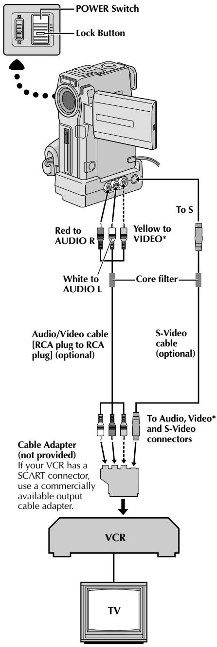
* Connect when an S-Video cable is not used.
Dubbing From A VCR
[To use this camcorder as a recorder: Only for GR-DVX10 owners]
1 Make sure all units are turned off, then connect the camcorder and the VCR as shown in the illustration. Also refer to pg. 56 and 57.
2 Set "SOUND MODE" to "12 BIT" or "16 BIT" and "REC MODE" to "SP" or "LP" in the Menu Screen depending on your preference (13 pg. 11, 26, 27).
3 Set the camcorder's POWER Switch to "PLAY/PC" while pressing down the Lock Button located on the switch. Turn on the VCR's power and insert the appropriate cassettes in the camcorder and the VCR.
4 Set "AV/S-VIDEO" to "IN" in the Menu Screen to engage the analogue input mode (pg. 41).
5 Press START/STOP on the camcorder to engage the Record-Pause mode. "AV. IN" appears on the screen.
6 Engage the VCR's Play mode, then engage the StillPlayback mode when you have found a spot just before the edit-in point.
7 Press START/STOP on the camcorder to engage the Record mode. "AV_IN" appears on the screen. Engage the VCR's Play mode.
8 To stop dubbing, press START/STOP on the camcorder so that "AV. IN" reappears, then engage the VCR's Stop mode.
0 Repeat steps 6 through 8 for additional editing.
10 Set "AV/S-VIDEO" back to "OUT" in the Menu Screen to disengage the analogue input mode (pg. 41).
NOTES:
- When connecting the cables, make sure to connect the ends with a core filter to the camcorder. The core filter reduces interference.
- To use an output cable adapter (commercially available), refer to its instructions.
- It is recommended to use the AC Power Adapter/ Charger as the power supply instead of the battery pack (13 pg. 7).
- Analogue signals can be converted to digital signals with this procedure.
- It is also possible to dub from another camcorder.
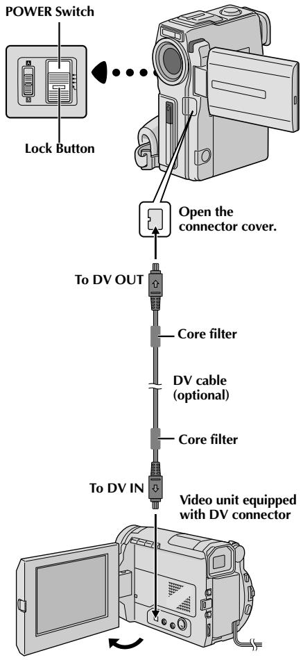
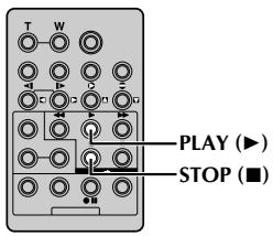
Dubbing To A Video Unit Equipped With A DV Connector (Digital Dubbing)
It is also possible to copy recorded scenes from the camcorder onto another video unit equipped with a DV connector. Since a digital signal is sent, there is little if any image or sound deterioration.
[To use this camcorder as a player]
1 Make sure the camcorder's power is off.
2 Connect the camcorder to your video unit equipped with a DV connector using a DV cable as shown in the illustration.
3 Set the camcorder's POWER Switch to "PLAY/PC" while pressing down the Lock Button located on the switch. Press to play back the source tape.
4 While watching the playback on the monitor, engage the DV connector-equipped video unit's record mode from the spot on the source tape you want to begin recording.
NOTES:
- It is recommended to use the AC Power Adapter/ Charger as the power supply instead of the battery pack (E pg. 7).
- If the remote control is used when both the player and recorder are JVC video units, both units will perform the same operation. To prevent this from happening, press the buttons on both units.
- For Digital Dubbing, this camcorder can be connected only to one device at a time.
- If a blank portion or disturbed image is played back on the player during dubbing, the dubbing may stop so that an unusual image is not dubbed.
- Even though the DV cable is connected correctly, sometimes the image may not appear in step 3. If this occurs, turn off the power and make connections again.
- If "Playback Zoom" (║ pg. 68), "Playback Special Effects" (║ pg. 69) or "Snapshot" is attempted during playback, only the original playback image recorded on the tape is output from the DV OUT connector.
- When using a DV cable, be sure to use the optional JVC VC-VDV204U DV cable.
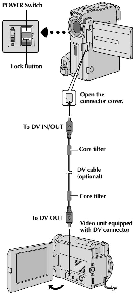
Dubbing From A Video Unit Equipped With A DV Connector (Digital Dubbing)
[To use this camcorder as a recorder: Only for GR-DVX10 owners]
NOTE:
Before the following steps, make sure that "AV/S-VIDEO" is set to "OUT" in the Menu Screen (13 pg. 41).
1 Make sure all units are turned off. Connect the camcorder to a video unit equipped with a DV output connector using a DV cable as shown in the illustration.
2 Set "REC MODE" to "SP" or "LP" in the Menu Screen depending on your preference (pg. 11).
3 Set this camcorder's POWER Switch to "PLAY/PC" while pressing down the Lock Button located on the switch. Turn on the video unit's power and insert the appropriate cassettes in the camcorder and the video unit.
4 Press START/STOP on the camcorder to engage the Record-Pause mode. "DV.IN" appears on the screen.
5 Engage the video unit's Play mode, then engage the Still Playback mode when you have found a spot just before the edit-in point.
6 Press START/STOP on the camcorder to engage the Record mode. "DV.IN" appears on the screen. Engage the video unit's Play mode.
7 To stop dubbing, press START/STOP on the camcorder so that "DV. IN" reappears, then engage the video unit's Stop mode.
Repeat steps 5 through 7 for additional editing.
NOTES:
- It is recommended to use the AC Power Adapter/ Charger as the power supply instead of the battery pack (13 pg. 7).
- If the remote control is used when both the player and recorder are JVC video units, both units will perform the same operation. To prevent this from happening, press the buttons on both units.
- For Digital Dubbing, this camcorder can be connected only to one device at a time.
- If a blank portion or disturbed image is played back on the player during dubbing, the dubbing may stop so that an unusual image is not dubbed.
- Even though the DV cable is connected correctly, sometimes the image may not appear in step 5. If this occurs, turn off the power and make connections again.
- When using a DV cable, be sure to use the optional JVC VC-VDV204U DV cable.
- Digital Dubbing is performed in the sound mode recorded on the original tape, regardless of the current "SOUND MODE" setting (F pg. 27).
- During Digital Dubbing, no signals are output from the video or audio connectors.
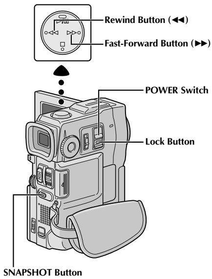
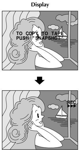
Dubbing Images Stored In A MultiMediaCard To A Tape
Images can be dubbed from a MultiMediaCard to a tape.
1 Load a MultiMediaCard (pg. 12) and cassette (pg. 10).
2 Set the POWER Switch to "PLAY/PC" while pressing down the Lock Button located on the switch. Open the LCD monitor fully or pull out the viewfinder fully.
3 To locate the point where you wish to dub a still image, play back the tape. Stop playback at the desired point.
4 Set the POWER Switch to "MEMORY" while pressing down the Lock Button located on the switch. To select a still image to be dubbed, perform Index Playback (pg. 47), Auto Playback (pg. 45) or press or to select the image you wish.
5 To engage Dub-Standby, press SNAPSHOT. The message "TO COPY TO TAPE PUSH "SNAPSHOT" appears.
6 While the message is being displayed, press SNAPSHOT again. The selected still image is recorded on the tape for approx. 6 seconds. The REC indicator disappears when dubbing is complete.
NOTES:
- If SNAPSHOT is pressed in step 5 when the tape's erase protection tab is set to "SAVE", the message "COPYING Failed" is displayed.
- The XGA image is dubbed onto the tape at 720 × 480 pixels.
- You can superimpose a print frame over the selected still image to be dubbed (13 pg. 51) and dub it to a tape. After step 4, superimpose a print frame over the still image and go to step 5.
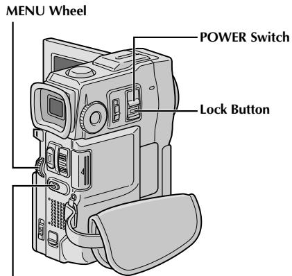
SNAPSHOT Button
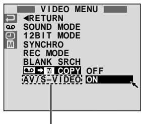
GR-DVX10 only
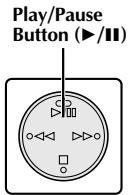
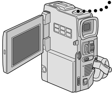
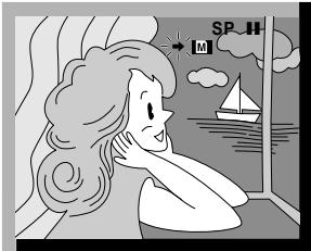
Display
Dubbing Images Recorded On A Tape To A MultiMediaCard
Images can be dubbed from a tape to a MultiMediaCard.
1 Load a MultiMediaCard (pg. 12) and cassette (pg. 10).
2 Set the POWER Switch to "PLAY/PC" while pressing down the Lock Button located on the switch. Open the LCD monitor fully or pull out the viewfinder fully.
Press the MENU wheel. The Menu Screen appears. Rotate it to select "o" and press it. "VIDEO MENU" appears.
4 Rotate the MENU wheel to select " M COPY" and press it. The Sub Menu appears. Rotate it to select "ON" and press it. Selection is complete.
Rotate the MENU wheel to select "RETURN" and press it twice. The normal playback screen resumes.
6 To select a video image to be dubbed, start playback by pressing /II. At the moment you find the image you wish to dub, press it again to engage Still Playback.
To start dubbing, press SNAPSHOT. The selected image is stored in the MultiMediaCard. "▶" blinks during dubbing.
NOTES:
- If SNAPSHOT is pressed in step 7 when a MultiMediaCard is not loaded, the message "COPYING Failed" is displayed.
- If an image recorded on the tape using the WIDE mode (13 pg. 28) is dubbed to a MultiMediaCard, the WIDE mode identifying signal is not dubbed with it.
- To use Playback Special Effects with a video image you wish to dub, perform up to step 7 using the remote control (provided) (13 pg. 69).
Images are dubbed in VGA file size.
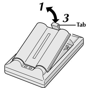
↓
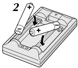
The Full-Function Remote Control Unit can operate this camcorder from a distance as well as the basic operations (Playback, Stop, Pause, Fast-Forward and Rewind) of your VCR. It also makes additional playback functions possible.
Installing The Batteries
The remote control uses two "AAA (R03)" size batteries. See "General Battery Precautions" (pg. 93).
1
Remove the battery compartment cover while pushing up the tab as illustrated.
2
Insert two "AAA (R03)" size batteries in the correct direction.
3
Re-attach the battery compartment cover.
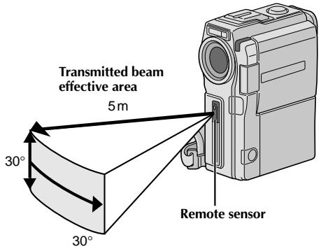
When using the remote control, be sure to point it at the remote sensor. The illustration shows the approximate transmitted beam effective area for indoor use.
The transmitted beam may not be effective or may cause incorrect operation outdoors or when the remote sensor is directly exposed to sunlight or powerful lighting.
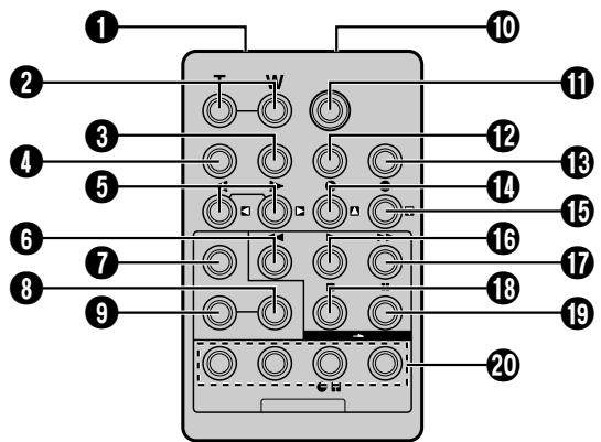
| Buttons | Functions | |
| With the camcorder's POWER Switch set to the camera position ("CAMERA"). | With the camcorder's POWER Switch set to "PLAY/PG" or "MPEG4". | |
| 1 Infrared beam transmitting window | Transmits the beam signal. | |
| 2 Zoom (T/W) Buttons | Zoom in/out (3 pg. 20) | Zoom in/out (3 pg. 68) |
| 3 DISPLAY Button | — | 3 pg. 71 |
| 4 SHIFT Button | — | 3 pg. 68, 70 |
| 5 SLOW Rewind/Forward Buttons Left/Right Buttons | — | 3 pg. 68 3 pg. 68 |
| 6 REW Button | — | • Rewind/Reverse Shuttle Search on a tape (3 pg. 40) • Displays previous image in a MultiMediaCard (3 pg. 45) |
| 7 FADE/WIPE Button | — | 3 pg. 72 |
| 8 EFFECT ON/OFF Button | — | 3 pg. 69 |
| 9 EFFECT Button | — | 3 pg. 69 |
| 10 PAUSE IN Connector | — | 3 pg. 71 |
| 11 START/STOP Button | Functions the same as START/STOP on the camcorder. | |
| 12 MBR SET Button | — | 3 pg. 70 |
| 13 SNAPSHOT Button | Functions the same as SNAPSHOT on the camcorder. | |
| 14 Up Button INSERT Button* | — | 3 pg. 68 |
| 15 Down Button A. DUB Button | — | 3 pg. 68 3 pg. 76 |
| 16 PLAY Button | — | • Starts playback of a tape (3 pg. 40) • Starts AutoPlayback of a MultiMediaCard (3 pg. 45) |
| 17 FF Button | — | • Forward/Forward Shuttle Search on a tape (3 pg. 40) • Displays next image in a MultiMediaCard (3 pg. 45) |
| 18 STOP Button | — | • Stops the tape (3 pg. 40) • Stops Auto Playback (3 pg. 45) |
| 19 PAUSE Button | — | Pauses the tape (3 pg. 68) |
| 20 R.A.EDIT Buttons | — | 3 pg. 70–75 |
- This function is unavailable with this camcorder.
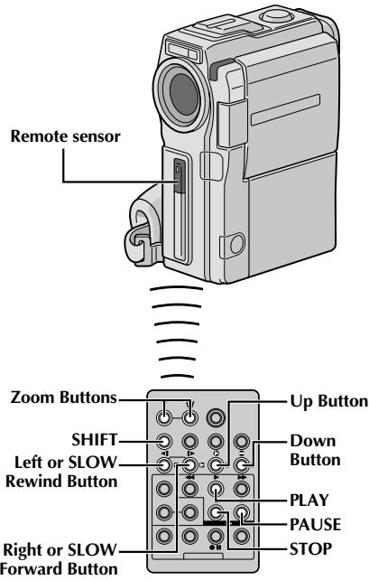

Normal playback
Press T


To move image, press (Right) while keeping SHIFT held down.
FEATURE: Slow-Motion Playback
PURPOSE:
To allow slow-speed search in either direction during video playback.
OPERATION:
1) To change from normal to Slow-Motion Playback, press SLOW (or more than approx. 2 seconds. After approx. 1 minute in Slow Rewind or approx. 2 minutes in Slow Forward, normal playback resumes.
To stop Slow-Motion Playback, press PLAY (▶).
NOTES:
- You can also engage Slow-Motion Playback from Still Playback by pressing SLOW more than approx. 2 seconds.
- During Slow-Motion Playback, due to digital image processing, the picture may take on a mosaic effect.
- After SLOW (or▶) is pressed and held, the still image may be displayed for a few seconds, followed by a blue screen for a few seconds. This is not a malfunction.
- There may be a small margin between the slow-motion playback start point you chose and the actual start point for Slow-Motion Playback.
- During Slow-Motion Playback, there will be disturbances in video and the picture may seem unstable, especially with steady images. This is not a malfunction.
- During Slow-Motion Playback, press PAUSE (II) to pause playback.
FEATURE: Frame-By-Frame Playback
PURPOSE:
To allow frame-by-frame search during video playback.
OPERATION:
1) To change from normal to Frame-By-Frame Playback, press SLOW () repeatedly for forward or SLOW () repeatedly for reverse. Each time it is pressed, the frame is played back.
NOTE:
You can also engage Frame-By-Frame Playback from Still Playback by pressing SLOW (or) repeatedly.
FEATURE: Playback Zoom
PURPOSE:
To magnify the recorded image up to 10X at any time during playback.
OPERATION:
1) Press PLAY () to find the scene of interest.
2) Press the Zoom Buttons (T/W) on the remote control. Make sure the remote control is pointed at the camcorder's remote sensor. Pressing T zooms in.
3) You can move the image on screen around to find a particular portion of the picture. While holding down SHIFT, press (Left), (Right), (Up) and (Down).
To end zoom, press and hold W until magnification returns to normal. Or, press STOP (■) and then press PLAY (▶).
NOTES:
- Zoom can also be used during slow-motion and still playback.
- Due to digital image processing, the quality of the image may suffer.
- Playback Zoom cannot be used on images that were recorded with the MODE Dial set to "PS".
PLAYBACK EFFECT
PLAYBACK EFFECT Select Menu
OFF
1 CLASSIC FILM
2 B/W MONOTONE
3 SEPIA
4 STROBE
5VIDEO ECHO
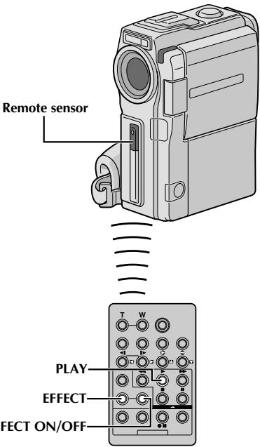
FEATURE:Playback Special Effects
PURPOSE:
To allow you to add creative effects to the video playback image.
OPERATION:
1) To start playback, press PLAY (▶).
2) Point the remote control at the camcorder's remote sensor and press EFFECT. The PLAYBACK EFFECT Select Menu appears.
3) Move the highlight bar to the desired effect by pressing EFFECT. The selected function is activated and after 2 seconds the menu disappears.
To deactivate the selected effect, press EFFECT ON/OFF on the remote control. Pressing it again reactivates the selected effect.
To change the selected effect, repeat from step 2 above.
NOTE:
The effects that can be used during playback are Classic Film, Monotone, Sepia, Strobe and Video Echo. The effects work the same in playback as they did in recording. Refer to page 36 for more information.
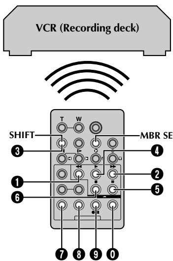
VCR CODE LIST
| VCR BRAND NAME | BUTTONS (A) (B) |
| AKAI | 6 2 3 4 7 7 |
| BLAUPUNKT | 1 3 |
| FERGUSON | 9 7 9 8 3 2 |
| GRUNDIG | 1 1 3 4 |
| HITACHI | 6 6 6 3 |
| JVC A | 9 1 9 6 3 |
| B | 9 6 9 3 |
| C | 9 3 |
| MITSUBISHI | 6 7 6 8 |
| NEC | 3 7 3 8 |
| PANASONIC | 1 3 1 7 1 9 1 1 8 |
| VCR BRAND NAME | BUTTONS (A) (B) |
| PHILIPS | 1 9 9 6 1 1 9 1 9 1 9 6 1 2 3 3 7 2 |
| SANYO | 3 6 3 5 |
| SELECO, REX | 9 1 9 6 |
| SHARP | 1 5 1 0 |
| SONY | 6 5 6 0 9 9 3 1 |
| THOMSON, TELEFUNKEN, SABA, NORDMENDE | 9 1 9 6 9 7 3 2 |
| TOSHIBA | 6 9 6 1 |
Random Assemble Editing [R.A.Edit]
Create edited videos easily using your camcorder as the source player. You can select up to 8 "cuts" for automatic editing, in any order you like. R.A.Edit is more easily performed when the MBR (Multi-Brand Remote) is set to operate with your brand of VCR (see VCR CODE LIST), but can also be performed by operating the VCR manually.
Before operation, make sure the batteries are installed in the remote control (13 pg. 66).
SET REMOTE/VCR CODE
1 Turn off the power to the VCR and point the remote towards the VCR's infrared sensor. Then, referring to the VCR CODE LIST, press and hold MBR SET, and press button (A) and then (B). The code is automatically set once you release MBR SET, and the VCR's power comes on.
2 Make sure the VCR's power is on. Then, while holding SHIFT, press the button on the remote for the desired function. The functions the remote can control are PLAY, STOP, PAUSE, FF, REW and VCR REC STBY (you do not need to press SHIFT for this one).
You are now ready to try Random Assemble Editing.
IMPORTANT
Although the MBR is compatible with JVC VCRs and those of many other makers, it may not work with yours or may offer limited functions.
NOTES:
- If the VCR's power does not come on in step 1, try another code from the VCR CODE LIST.
- Some brands of VCR do not come on automatically. In this case, turn the power on manually and try step 2.
- If the remote control is not able to control the VCR, use the controls on the VCR.
- When the remote control's batteries run out, the VCR brand you have set will be erased. In that case, replace the old battery with a new one to reset the VCR brand.
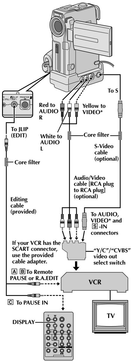
* Connect when an S-Video cable is not used.
ATTENTION FOR EDITING CABLE
- Be careful not to mistake it for the JLIP cable (F pg. 4).
- Make sure you connect the end with the core filter to the camcorder.
MAKE CONNECTIONS
Also refer to pg. 56 and 57.
1 A JVC VCR equipped with a remote pause connector . . .
... connect the editing cable to the Remote PAUSE connector.
A JVC VCR not equipped with a remote pause connector but equipped with an R.A. EDIT connector . . .
... connect the editing cable to the R.A.EDIT connector.
C A VCR other than above . . .
... connect the editing cable to the remote control's PAUSE IN connector.
2 Insert a recorded tape into the camcorder and set the POWER Switch to "PLAY/PC" while pressing down the Lock Button located on the switch.
3 Turn the VCR power on, insert a recordable tape and engage the AUX mode (refer to the VCR's instructions).
NOTES:
- Before Random Assemble Editing, make sure the indications do not appear on the TV monitor. If they do, they will be recorded onto the new tape.
To choose whether or not the following displays appear on the connected TV... - Date/Time
... set "DATE/TIME" to "AUTO", "ON" or "OFF" in the Menu Screen (13 pg. 41).
Time Code
... set "TIME CODE" to "ON" or "OFF" in the Menu Screen (pg. 41). - Playback Sound Mode, Tape Speed And Tape Running Displays
... set "ON SCREEN" to "LCD" or "SIMPLE" in the Menu Screen (pg. 41). Or, press DISPLAY on the remote control.
- For GR-DVX10 owners: Make sure to set "AV/S-VIDEO" to "OUT" in the Menu Screen (F pg. 41).
- When connecting the cables, make sure to connect the ends with a core filter to the camcorder. The core filter reduces interference.
- Set the video out select switch of the cable adapter as required:
Y/C : When connecting to a TV or VCR which accepts Y/C signals and uses an S-Video cable.
CVBS : When connecting to a TV or VCR which does not accept Y/C signals and uses an audio/video cable.
- When editing on a VCR equipped with a DV input connector, an optional DV cable can be connected instead of an S-Video cable and audio/video cable.
- You can use the AV OUT connector on the camcorder for connection.
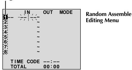
Programme
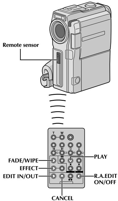
SELECT SCENES
4 Point the remote control at the camcorder's remote sensor. Press PLAY () and then press R.A.EDIT ON/OFF on the remote control. The Random Assemble Editing Menu appears.
5 If using a Fade/Wipe at the beginning of the scene, press FADE/WIPE on the remote control.
- Cycle through the effects by pressing repeatedly, and stop when the one you want is displayed.
- You cannot use a Picture Wipe/Dissolve at the beginning of Programme 1.
6 At the beginning of the scene, press EDIT IN/OUT on the remote control. The Edit-In position appears in the Random Assemble Editing Menu.
7 At the end of the scene, press EDIT IN/OUT. The Edit-Out position appears in the Random Assemble Editing Menu.
8 If using a Fade/Wipe at the end of the scene, press FADE/WIPE.
- Cycle through the effects by pressing repeatedly, and stop when the one you want is displayed.
- If you select a Fade/Wipe effect for an Edit-Out point, the effect is automatically applied to the following Edit-In point.
- You cannot use a Picture Wipe/Dissolve at the end of the last scene.
- When you use Fade/Wipe effects, that time is included in the total time (this does not apply to Picture Wipe/Dissolve).
9 If using Playback Special Effects, press EFFECT pg. 69.
10 Repeat steps 6 through 9 to register additional scenes.
To change previously registered points, press CANCEL on the remote control. The registered points disappear, one at a time, from the most recently registered point.
- If you are not using Fade/Wipe or Programme AE with special effects, repeat steps 6 and 7 only.
NOTES:
- When choosing a scene, set Edit-In and Edit-Out points so that there is a relatively large difference between them.
- If the search time for an in-point exceeds 5 minutes, the recording deck's Record-Standby mode will be cancelled and editing will not take place.
- If there are blank portions before or after the Edit-In and Edit-Out points, a blue screen may be included in the edited version.
- Since time codes register time only as accurately as seconds, the time code total time may not match the total programme time exactly.
- Turning off the camcorder's power erases all registered Edit-In and Edit-Out points.
- If you select Sepia or Monotone mode from Programme AE with special effects, you cannot use the Dissolve or Black & White Fader. In this case the Dissolve or Black & White indicator begins blinking. Once the next Edit-In point is registered, the effect is turned off. To combine these effects, use Sepia or Monotone during recording, then use the Dissolve or Black & White Fader during Random Assemble Editing.
- It is not possible to use Fade/Wipe effects and Programme AE with special effects during Random Assemble Editing using a DV cable.
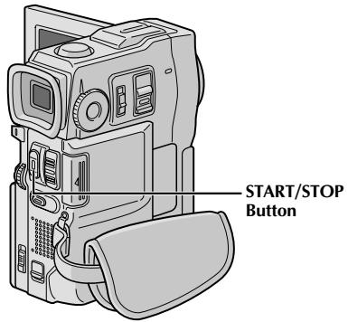
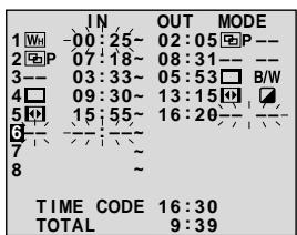
Random Assemble Editing Menu
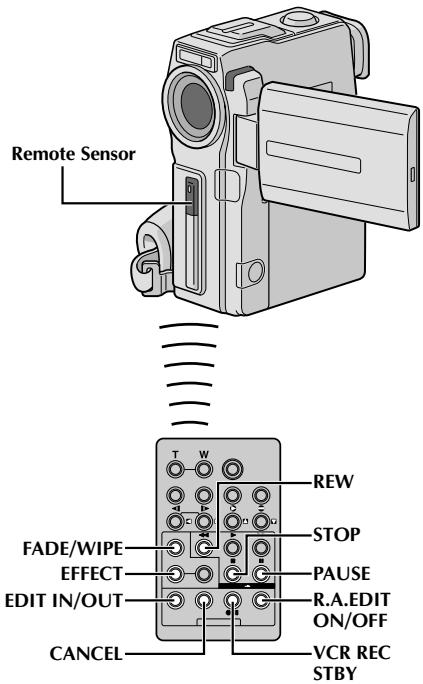
AUTOMATIC EDITING TO VCR
11 Rewind the tape in the camcorder to the beginning of the scene you want to edit and press PAUSE (II).
12 Point the remote control towards the VCR's remote sensor and press VCR REC STBY (●II), or manually engage the VCR's Record-Pause mode.
13 Press START/STOP on the camcorder. Editing proceeds as programmed, right through to the end of the last registered scene.
- Pressing START/STOP on the remote control does not start editing.
- When dubbing is complete, the camcorder enters the Pause mode, and the VCR enters its Record-Pause mode.
- If you do not register an Edit-Out point, the tape will be dubbed all the way to the end automatically.
- If you operate the camcorder during automatic editing, the VCR will enter its Record-Pause mode and automatic editing will stop.
14 Engage the Stop modes for the camcorder and the VCR.
To make the R.A.Edit counter display disappear, press R.A EDIT ON/OFF on the remote control.
NOTES:
- Pressing R.A.EDIT ON/OFF on the remote control clears all settings registered during Random Assemble Editing.
- When the editing cable is connected to the remote control's Pause In connector during dubbing, make sure the remote control is pointed at the VCR's sensor, and the path between the two is unobstructed.
- Random Assemble Editing may not function properly when using a tape including several duplicated time codes (13 pg. 21).
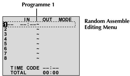
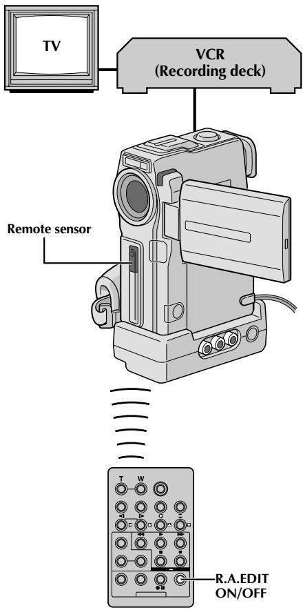
For More Accurate Editing
Some VCRs make the transition from Record-Pause to Record mode faster than others. Even if you begin editing for the camcorder and the VCR at exactly the same time, you may lose scenes you wanted, or find that you have recorded scenes you did not want. For a cleanly edited tape, confirm and adjust the timing of the camcorder against your VCR.
DIAGNOSING VCR/CAMCORDER TIMING
1 Play back the tape in the camcorder, then point the remote control at the camcorder's remote sensor and press R.A.EDIT ON/OFF. The Random Assemble Editing Menu appears.
2 Perform Random Assemble Editing on Programme 1 only. In order to check VCR and camcorder timing, select the beginning of a scene transition as your Edit-In point.
3 Play back the dubbed scene. If any images from the scene prior to the transition you chose for your Edit-In point were recorded, that means your VCR moves too quickly from Record-Pause to Record mode.
- If the scene you tried to dub starts in progress, the VCR is slow to start recording.
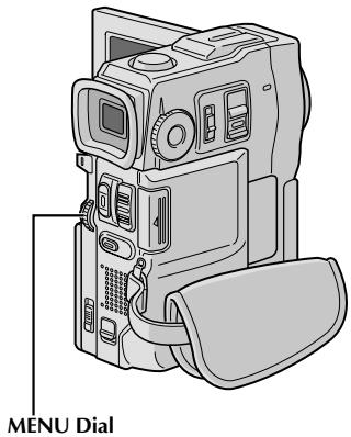
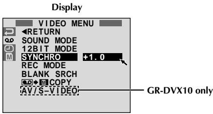
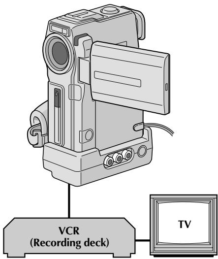
ADJUSTMENT OF VCR/CAMCORDER TIMING
4 Point the remote control at the camcorder's remote sensor and press R.A.EDIT ON/OFF to make the Random Assemble Editing menu disappear, then press the MENU wheel. The Menu Screen appears.
Rotate the MENU wheel to select "0" and press it. "VIDEO MENU" appears. Then, rotate it to "SYNCHRO" and press it. The value for "SYNCHRO" is highlighted.
6 Based on the diagnostics performed (pg. 74), you can now advance the VCR's record timing by rotating the MENU wheel towards "+" . You can also delay the VCR's record timing by rotating the MENU wheel towards "-. The adjustment range is from -1.3 to +1.3 seconds, in 0.1-second increments. Press the MENU wheel to finish the setting.
7 Rotate the MENU wheel to select "RETURN" and press it twice. Now perform Random Assemble Editing beginning with step 4 on page 72.
NOTES:
- Before performing actual Random Assemble Editing, do a few Random Assemble Editing trial runs to check whether the value you have input is appropriate or not, and make adjustments accordingly.
- Depending on the recorder, there may be situations where the timing difference cannot be fully corrected.

Display
Audio Dub Standby mo
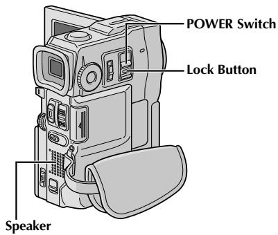
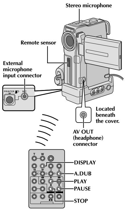
Audio Dubbing
The audio track can be customized only when recorded in the 12-bit mode (F pg. 27).
NOTES:
- Audio Dubbing is not possible on a tape recorded in 16-bit audio, on a tape recorded in the LP mode or on a blank portion of a tape.
To perform Audio Dubbing while watching on the television, make connections (13 pg. 56).
1 Play back the tape to locate the point where editing will start, then press PAUSE (II).
While holding A.DUB () on the remote control, press PAUSE (II). "II" appears.
Press PLAY () , then begin "narrating". Speak into the microphone.
- To pause dubbing, press PAUSE (II).
4 To end Audio Dubbing, press PAUSE (II), then STOP (I).
To hear the dubbed sound during playback . . .
... set "12BIT MODE" to "SOUND 2" or "MIX" in the Menu Screen (pg. 41, 42).
NOTES:
- Audio dubbing is also possible using an optional microphone connected to the MIC connector on the Docking Station.
Sound is not heard from the speaker during Audio Dubbing. To hear sound, connect optional headphones to the AV OUT connector. - While an optional microphone is connected, the built-in microphone is disabled.
- When editing onto a tape that was recorded at 12-bit, the old and new soundtracks are recorded separately.
- If you dub onto a blank space on the tape, the sound may be disrupted. Make sure you only edit recorded areas.
- If feedback or howling occurs during TV playback, move the camcorder's microphone away from the TV, or turn down the TV's volume.
- If you change from 12-bit to 16-bit in mid-recording and then use the tape for Audio Dubbing, it is not effective from the point where 16-bit recording began.
- During Audio Dubbing, when the tape moves to scenes recorded in the LP mode, scenes recorded in 16-bit audio or a blank portion, Audio Dubbing stops pg. 91).
- For GR-DVX10 owners: To perform Audio Dubbing with a video unit connected to the camcorder's AV connector, first set "AV/S-VIDEO" to "IN" in the Menu Screen (F) pg. 41). You can hear sound from the video unit using optional headphones.
Display

Audio Dub Standby mode
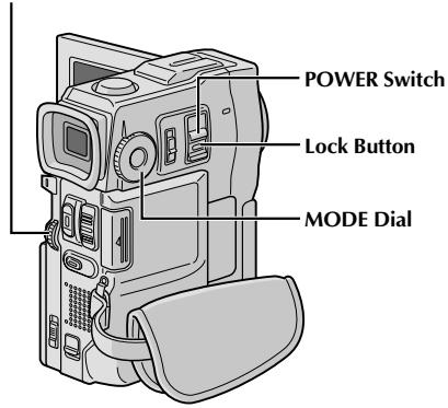
MENU Wheel
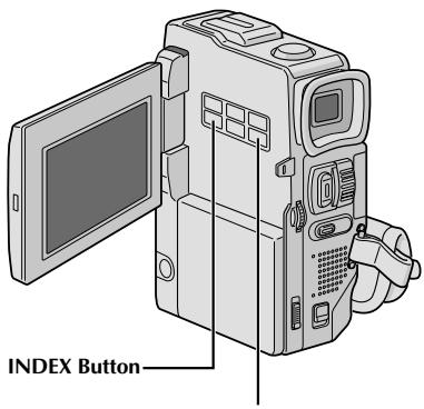
DIGITAL SOUND Button
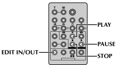
Audio Dubbing Using Digital Sound Effects
1 Load the provided MultiMediaCard (pg. 12) and perform step 1 and 2 of page 76.
Press EDIT IN/OUT so that ^ appears.
- To select the sound effect, press INDEX to display the SOUND Index Screen (43 pg. 47), then use the MENU wheel to select the desired sound effect.
- If no Digital Sound Effect is displayed the microphone input will be dubbed onto the tape.
Press PLAY () to begin Audio Dubbing.
4 Press DIGITAL SOUND where you want to use the sound effect.
- The displayed sound effect blinks while it is being dubbed.
- To stop dubbing the sound effect midway, press DIGITAL SOUND again.
Press STOP (■) to end Audio Dubbing.
NOTES:
The dubbed sound effect is recorded on SOUND 2 (13 pg. 42).
- If you press PAUSE (II) to pause dubbing in step 4 the selected sound effect indication remains displayed.
- If you press STOP (■) to end Audio Dubbing in step 5 the selected sound effect continues to be heard from the connected headphones (optional); press DIGITAL SOUND to stop the sound effect.
After Use
1 Turn off the camcorder.
2 Slide down and hold OPEN/EJECT in the direction of the arrow, then pull the cassette holder cover open until it locks. The cassette holder opens automatically. Remove the cassette.
Press "PUSH HERE" to close the cassette holder.
- Once the cassette holder is closed, it recedes automatically. Wait until it recedes completely before closing the cassette holder cover.
4 Open the card cover, then press EJECT. The MultiMediaCard is disengaged from the camcorder. Remove the MultiMediaCard.
5 Close the card cover.
6 Slide down BATT. RELEASE ① and remove the battery pack ② ③.
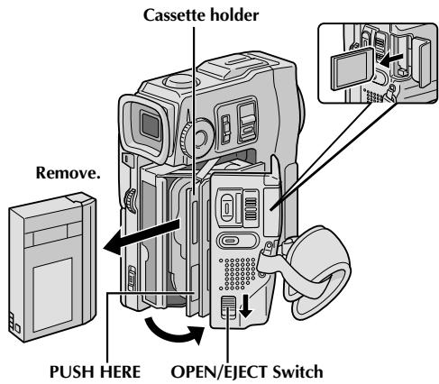
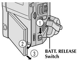
Cleaning The Camcorder
1 To clean the exterior, wipe gently with a soft cloth. Put the cloth in diluted mild soap and wring it well to wipe off heavy dirt. Then wipe again with a dry cloth.
2 Open the LCD monitor. Wipe gently with a soft cloth. Be careful not to damage the monitor. Close the LCD monitor.
3 To clean the lens, blow it with a blower brush, then wipe gently with lens cleaning paper.
Pull out the viewfinder fully.
5 Open the viewfinder cleaning hatch in the direction of the arrow 1. Insert a lens blower or soft cloth into the gap at the side of the viewfinder and clean the interior of the viewfinder with it 2.
6 Close the hatch until it locks in place and push the viewfinder back in.
NOTES:
- Avoid using strong cleaning agents such as benzine or alcohol.
- Cleaning should be done only after the battery pack has been removed or other power units have been disconnected.
- Mould may form if the lens is left dirty.
- When using a cleaner or chemically treated cloth refer to the cautions of each product.
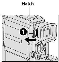
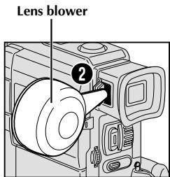
If, after following the steps in the chart below, the problem still exists, please consult your nearest JVC dealer.
The camcorder is a microcomputer-controlled device. External noise and interference (from a TV, a radio, etc.) might prevent it from functioning properly. In such cases, first disconnect its power supply unit (battery pack, AC Power Adapter/Battery Charger, etc.) and wait a few minutes; and then re-connect it and proceed as usual from the beginning.
| SYMPTOM | POSSIBLE CAUSES | CORRECTIVE ACTION |
| 1. No power is supplied. | 1. • The power is not connected properly. • The battery is dead. • The LCD monitor is not open fully or the viewfinder is not pulled out when recording. | 1. • Connect the AC Power Adapter/Charger securely (║ pg. 7). • Replace the dead battery with a fully charged one (║ pg. 6, 7). • Open the LCD monitor fully or pull out the viewfinder. |
| 2. “SET DATE/TIME!” appears. | 2. • The built-in clock's rechargeable lithium battery is discharged. • The previously set date/time is erased. | 2. • Connect the camcorder to an AC outlet using the AC Power Adapter/Charger for over 24 hours to charge the clock's lithium battery (║ pg. 9). |
| 3. Recording cannot be performed. | 3. • The tape's erase protection tab is set to “SAVE”. • The POWER Switch is set to “PLAY/PC”, “MEMORY” or “OFF”. • “TAPE END” appears. • The cassette holder cover is open. | 3. • Set the tape's erase protection tab to “REC” (║ pg. 10). • Set the POWER Switch to “CAMERA” (║ pg. 14). • Replace with new cassette (║ pg. 10). • Close the cassette holder cover. |
| 4. There is no picture. | 4. • The camcorder is not getting power, or some other malfunction exists. | 4. • Turn the camcorder's power off and on again (║ pg. 16). |
| 5. Some functions are not available using the MENU wheel. | 5. • The Operation Switch is set to “A”. | 5. • Set the Operation Switch to “M” (║ pg. 14). |
| 6. The focus does not adjust automatically. | 6. • Focus is set to the Manual mode. • The recording was done in a dark place, or the contrast was low. • The lens is dirty or covered with condensation. | 6. • Set Focus to the Auto mode (║ pg. 25). • Clean the lens and check the focus again (║ pg. 78). |
| 7. The cassette will not load properly. | 7. • The cassette is in the wrong position. • The battery's charge is low. | 7. • Set it in the right position (║ pg. 10). • Install a fully charged battery (║ pg. 6, 7). |
| 8. The MultiMediaCard will not load properly. | 8. • The MultiMediaCard is in the wrong position. | 8. • Set it in the right position (║ pg. 12). |
| 9. In the 5-Second mode, recording ends before 5 seconds have elapsed. | 9. • The 5-Second mode is set to “ANIM.” in the Menu Screen. | 9. • Select “5S” in the Menu Screen (║ pg. 33). |
| 10. Snapshot mode cannot be used. | 10. • The Squeeze mode is selected. | 10. • Disengage the Squeeze mode (║ pg. 28). |
| 11. The colour of Snapshot looks strange. | 11. ·The light source or the subject does not include white. Or there are various different light sources behind the subject. ·The Sepia or Monotone mode is activated. | 11. ·Set “FLASH” to “ON” in the Menu Screen. Or find a white subject and compose your shot so that it also appears in the frame (Ø pg. 18, 19, 30). ·Turn off Sepia and Monotone (Ø pg. 36). |
| 12. Although Snapshot is attempted, flash does not take place. | 12. ·The subject is too bright with the flash set to “AUTO” or “AUTO”. ·If blinks, the flash is being charged. ·The camcorder is in the Record mode. ·In the Menu Screen, “GAIN UP” is set to “OFF” or “P.AE/EFFECT” is set to “TWILIGHT”. | 12. ·Set “FLASH” to “ON” in the Menu Screen (Ø pg. 30). ·It can take up to 10 seconds to charge the flash. ·Set the camcorder in the Record-Standby mode (Ø pg. 30). ·Set “GAIN UP” to “AUTO” or “AGC” (Ø pg. 27) or disengage the “TWILIGHT” mode (Ø pg. 36). |
| 13. Although a Snapshot is taken with the flash, Red-Eye Reduction does not take place. | 13. ·The subject does not look straight toward the flash. ·The subject does not look at the first flash, which is an important part of Red-Eye Reduction. ·The camcorder is too far from the subject. ·“FLASH” is not set to “AUTO” in the Menu Screen. | 13. ·The subject should look straight toward the flash, especially the first flash. If the subject does not see the first flash, it will be difficult for Red-Eye Reduction to take place (Ø pg. 30). ·The flash is effective for subjects at a distance of approx. 0.7 m to 2 m from the camcorder (Ø pg. 30). ·Set “FLASH” to “AUTO” in the Menu Screen to display the Red-Eye Reduction indicator (Ø pg. 30). |
| 14. The image taken using Snapshot is too dark. | 14. ·“FLASH” is set to “OFF” in the Menu Screen. ·The flash emission window is covered by fingers, etc.. ·The flash brightness is set to produce a darker image (adjustment value: -3). ·The camcorder is too far from the subject. ·Shooting was performed under backlit conditions. | 14. ·Set “FLASH” to any position except “OFF” in the Menu Screen (Ø pg. 30). ·Do not cover the flash emission window. ·Adjust the flash brightness to a larger value (Ø pg. 31). ·The flash is effective for subjects at a distance of approx. 0.7 m to 2 m (Ø pg. 30). ·Press the BACKLIGHT Button (Ø pg. 38). |
| 15. The image taken using Snapshot is too bright. | 15. ·“FLASH” is set to “ON” in the Menu Screen. | 15. ·Set “FLASH” to any parameter other than “ON” in the Menu Screen (Ø pg. 30). |
| 16. Digital Zoom does not work. | 16. ·10X optical zoom is selected. ·The MODE Dial is set to “DUAL” or “DSC”. ·“P.AE/EFFECT” is set to “VIDEO ECHO” in the Menu Screen. ·“WIDE MODE” is set to “PS-WIDE” in the Menu Screen. ·Picture Wipe or Dissolve are being used in a scene transition. | 16. ·Set “ZOOM” to “40X” or “200X” in the Menu Screen (Ø pg. 27). ·Set the MODE Dial to “PS” or “VIDEO” (Ø pg. 15, 20). ·Disengage the “VIDEO ECHO” mode (Ø pg. 20, 36). ·Disengage the “PS-WIDE” mode (Ø pg. 28). ·Wait until the Picture Wipe or Dissolve effects are completed (Ø pg. 20, 34). |
| 17. Programme AE with special effects and Fade/Wipe Effects do not work. | 17. • The Operation Switch is set to “A”. | 17. • Set the Operation Switch to “M” (Lpg. 34, 36). |
| 18. The Black & White Fader does not work. | 18. • The Sepia or Monotone mode is activated. | 18. • Turn off Sepia and Monotone (Lpg. 34, 36). |
| 19. The Dissolve function does not work. | 19. • The Sepia, Monotone or Slow Shutter mode of Programme AE with special effects is activated. •“WIDE MODE” is set to “SQUEEZE” or “PS-WIDE” in the Menu Screen. •The previously selected mode of Programme AE with special effects was changed after the last selected scene for editing was registered. | 19. • Turn off Sepia, Monotone or Slow Shutter before adding Dissolve to a scene transition (Lpg. 34, 36). •Set “WIDE MODE” to “CINEMA” or “OFF” mode (Lpg. 28). •Make sure you have selected the mode of Programme AE with special effects you want before starting editing (Lpg. 34, 36). |
| 20. The Picture Wipe and Dissolve functions do not work. | 20. • The last selected editing scene is ending. •At the end of the last selected scene for editing, the POWER Switch was set to “OFF”. •The power is off. | 20. • Select Picture Wipe or Dissolve before beginning recording. The effects are then automatically activated (Lpg. 34). •Do not turn off the camcorder's power after setting Edit-In and Edit-Out points, as they will all be erased (Lpg. 34). •The camcorder automatically shuts off after 5 minutes have elapsed in the Record-Standby mode. Make sure you continue operations within 5 minutes after engaging Record-Standby mode (Lpg. 34). |
| 21. The picture wipe function does not work. | 21. • The Slow Shutter mode is activated. •“WIDE MODE” is not set to “OFF”. | 21. • Disengage the Slow Shutter mode or set “WIDE MODE” to “OFF” before preparing to use the Picture Wipe (Lpg. 28, 34, 36). |
| 22. Scene transition does not go as expected. | 22. • When using “Picture Wipe/Dissolve” (Lpg. 34), there is a delay of a fraction of a second between the previous record stop-point and the Dissolve start-point. This is normal, but this slight delay becomes especially noticeable when shooting fast-moving subject or during rapid panning. | 22. —— |
| 23. The Video Echo mode does not work. | 23. • The Picture Wipe or Dissolve functions are in use. •“WIDE MODE” is set to “SQUEEZE” or “PS-WIDE” in the Menu Screen. •A Fade-In or Fade-Out is in progress. | 23. • Set “WIDE MODE” to “CINEMA” or “OFF” mode (Lpg. 28). •Do not try to use the Video Echo mode during a Fade-In or Fade-Out (Lpg. 34, 36). |
| 24. Even when Slow Shutter is not selected, the image looks like it is activated. | 24. • When shooting in the dark, the unit becomes highly sensitive to light and the image takes on an effect similar to Slow Shutter. | 24. • If you want the lighting to look more natural, set GAIN UP to “AGC” or “OFF” in the Menu Screen (⓷ pg. 27). |
| 25. There is no strobe when the Classic Film or Strobe mode is activated. | 25. • The Picture Wipe or Dissolve function is in use. | 25. • Do not try to use the Classic Film or Strobe mode during a scene transition (⓷ pg. 34, 36). |
| 26. White Balance cannot be activated. | 26. • The Sepia or Monotone mode is activated. | 26. • Turn off Sepia or Monotone before setting White Balance (⓷ pg. 36, 39). |
| 27. When shooting a subject illuminated by bright light, vertical lines appear. | 27. • This is a result of exceedingly high contrast, and is not a malfunction. | 27. —— |
| 28. When the screen is under direct sunlight during shooting, the screen becomes red or black for an instant. | 28. • This is not a malfunction. | 28. —— |
| 29. During recording, the date/time does not appear. | 29. • “DATE/TIME” is set to “OFF” in the Menu Screen. • Self-Recording is performed. | 29. • Set “DATE/TIME” to “ON” in the Menu Screen (⓷ pg. 29). • During Self-Recording, the date/time does not appear (⓷ pg. 17). |
| 30. Files stored in the MultiMediaCard cannot be deleted. | 30. • Files stored in the MultiMediaCard are protected. | 30. • Remove protection from the files stored in the MultiMediaCard and delete them (⓷ pg. 48, 49). |
| 31. The indicators and messages do not appear. | 31. • “ON SCREEN” is set to “SIMPLE” or “TIME CODE” is set to “OFF” in the Menu Screen. | 31. • Set “ON SCREEN” to “LCD” or “LCD/TV” and set “TIME CODE” to “ON” in the Menu Screen (⓷ pg. 29, 41). |
| 32. Images on the LCD monitor appear dark or whitish. | 32. • In places subject to low temperature, images become dark due to the characteristics of the LCD monitor. When this happens, the displayed colours differ from those that are actually recorded. This is not a defect of the camcorder. • When the LCD monitor's fluorescent light reaches the end of its service life, images on the LCD monitor become dark. Consult your nearest JVC dealer. | 32. • Adjust the brightness and angle of the LCD monitor (⓷ pg. 16, 17). |
| 33. The rear of the LCD monitor is hot. | 33. • The light used to illuminate the LCD monitor causes it to become hot. | 33. • Close the LCD monitor to turn it off or set the POWER Switch to “OFF”, and let the unit cool down. |
| 34. The indicators and the image colour on the LCD monitor are not clear. | 34. • This may occur when the surface or the edge of the LCD monitor is pressed. | 34. —— |
| 35. The LCD monitor or viewfinder indications blink. | 35. • Certain Fade/Wipe effects, certain modes of Programme AE with special effects, “DIS” and other functions that cannot be used together are selected at the same time. | 35. • Re-read the sections covering Fade/Wipe effects, Programme AE with special effects and “DIS” (CP pg. 28, 34 – 36). |
| 36. Coloured bright spots appear all over the LCD monitor or the viewfinder. | 36. • The LCD monitor and the viewfinder are made with high-precision technology. However, black spots or bright spots of light (red, green or blue) may appear constantly on the LCD monitor or the viewfinder. These spots are not recorded on the tape. This is not due to any defect of the unit. (Effective dots: more than 99.99 %) | 36. |
| 37. During recording, sound cannot be heard. | 37. • The optional headphones are not connected to the headphones connector. • The sound volume of the headphones connector was not adjusted appropriately. The sound volume at this point is the same as the level it was adjusted to during playback. | 37. • Connect the optional headphones to the headphone connector (CP pg. 86, 87). • Adjust the sound volume during playback (CP pg. 40). |
| 38. Play, Rewind and Fast-Forward functions do not work. | 38. • The POWER Switch is not set to “PLAY/PC”. | 38. • Set the POWER Switch to “PLAY/PC” (CP pg. 40). |
| 39. A MultiMediaCard cannot be played back. | 39. • The POWER Switch is set to “CAMERA” or “PLAY/PC”. | 39. • Set the POWER Switch to “CAMERA” (CP pg. 45). |
| 40. The tape is moving, but there is no picture. | 40. • Your TV has AV input terminals, but is not set to its VIDEO mode. • The cassette holder cover is open. | 40. • Set the TV to the mode or channel appropriate for video playback (CP pg. 56, 57). • Close the cassette holder cover (CP pg. 10). |
| 41. The LCD monitor image is distorted. | 41. • During playback of the unrecorded portion, High-speed Search and still playback, LCD monitor indications appear distorted. This is not a defect. | 41. |
| 42. Images on the LCD monitor are jittery. | 42. • The speaker volume is too great. | 42. • Turn the speaker volume down (CP pg. 40). |
| 43. For GR-DVX10 owners: There is no playback picture on the connected TV. | 43. • Since the analogue input mode is engaged, the camcorder is in the Record-Standby mode. | 43. • Set “AV/S-VIDEO” to “OUT” in the Menu Screen (CP pg. 41). |
| 44. Blocks of noise appear during playback, or there is no playback picture and the screen becomes blue. | 44. | 44. • Clean the video heads with an optional cleaning cassette (CP pg. 94). |
| 45. The LCD monitor, the viewfinder and the lens have become dirty (ex. fingerprints). | 45. | 45. • Wipe them gently with soft cloth. Wiping strongly can cause damage (║ pg. 78). |
| 46. An unusual mark appears. | 46. | 46. • Check the section of the manual that explains LCD monitor/viewfinder indications (║ pg. 88 - 92). |
| 47. An error indication (E01 - E06) appears. | 47. • A malfunction of some kind has occurred. In this case the camcorder's functions become unusable. | 47. • Remove the power supply (battery pack, etc.) and wait a few minutes for the indication to clear. When it does, you can resume using the camcorder. If the indication remains even though you repeat the above two or three times, please consult your nearest JVC dealer. |
| 48. The charger indicator on the AC Power Adapter/Charger does not light. | 48. • The temperature of the battery is extremely high/low. Charging is difficult in places subject to extremely high/low temperatures. | 48. • To protect the battery, it is recommended to charge it in places with a temperature of 10°C to 35°C (║ pg. 93). |
| 49. Picture does not appear on the LCD monitor. | 49. • The viewfinder is pulled out. The LCD monitor's brightness setting is too dark. | 49. • Push the viewfinder back in. Adjust the brightness of the LCD monitor (║ pg. 16). If the monitor is tilted upward 180 degrees, open the monitor fully (║ pg. 16). |
| 50. When the image is printed from the printer, a black bar appears at the bottom of the screen. | 50. • This is not a malfunction. | 50. • By recording with “DIS” activated (║ pg. 28) this can be avoided. |
| 51. When the camcorder is connected via the DV connector, the camcorder does not operate. | 51. • The DV cable was plugged/unplugged with power turned on. | 51. • Turn the camcorder's power off and on again, then operate it. |
| 52. During transport, the lens cover opens. | 52. | 52. • Do not subject the camcorder to shock or excessive vibration during transport. Turn the camcorder on and off. The lens cover closes. |
| 53. The MultiMediaCard cannot be removed from the camcorder. | 53. | 53. • Push in the MultiMediaCard a few more times (║ pg. 12). |
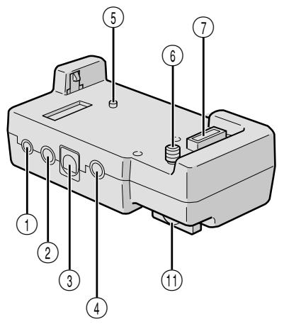
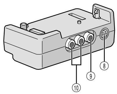
① PC Connector [DIGITAL STILL] ............ pg. 58
② J Terminal/Edit Connector [JLIP (Joint Level Interface Protocol) (EDIT)] 13 pg. 71
- Connect to a JLIP-compatible camcorder or VCR to control it from the computer using the provided Software.
NOTE:
Make sure that the camcorder is turned on while connecting the camcorder to a PC using the Docking Station's JLIP connector. If the camcorder is turned off (because the POWER Switch is set to "OFF" or due to Auto Shut Off* etc.) while the JLIP programme software is used, it will be impossible to control the connected devices from the computer. In such a case, first try turning the camcorder on again, or unplug the JLIP connection cable from the Docking Station's JLIP connector. Then, initialise or run the software again.
* Auto Shut Off:
If 5 minutes elapse in the Record-Standby mode or in the Pause mode, the camcorder's power shuts off automatically to conserve energy.
Connect the editing cable when performing Random Assemble Editing .70-75
③ PRINTER Connector Connect to the optional printer equipped with a PRINT DATA connector. Refer to the separate "FOR OWNERS OF AN OPTIONAL PRINTER" instruction sheet.
④ External Stereo Microphone Input Connector [MIC] pg. 76
⑤ Stud pg. 56
Screw. pg. 56
⑦ Multi Connector The Docking Station can be connected with this camcorder through this connector. Never touch it with your hand or hit it with a hard object; if the pins are damaged, the connectors will become unusable due to contact failure.
S-Video Input/Output Connector (GR-DVX10) S-Video Output Connector (GR-DVX9) [S] pg. 56, 71
⑨ Video Input/Output Connector (GR-DVX10)
Video Output Connector (GR-DVX9)
[VIDEO] pg. 56, 71
⑩ Audio Input/Output Connectors (GR-DVX10) Audio Output Connectors (GR-DVX9) [AUDIO L/R] pg. 56, 71
Screw Knob. pg. 56 To attach the camcorder, tighten this clockwise.
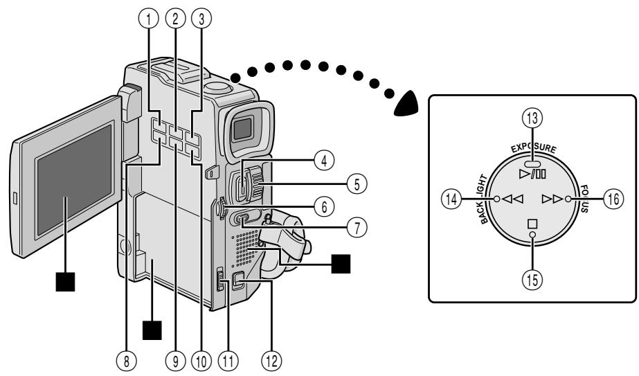
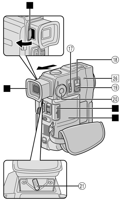
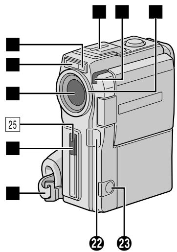
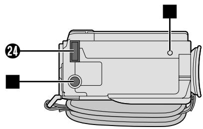
Controls
① PRINT Button
Enables printing using the optional printer equipped with a PRINT DATA connector. Refer to the separate "FOR OWNERS OF AN OPTIONAL PRINTER" instruction sheet.
② PRINT FRAME Button pg. 51
③ E-MAIL CLIP REC Button ... pg. 44
④ START/STOP Button. 16
⑤ • Power Zoom Lever [T/W] ............ pg. 20
- Speaker/Headphone Volume Control [VOL.] pg. 40
6 MENU Wheel [+, -, ] pg. 26
LCD Monitor Brightness Control [+, -] pg. 16
⑦ Snapshot Button
[SNAPSHOT] pg. 18, 19, 22, 24, 65
8 INDEX Button. pg. 37, 46, 47
⑨ IMAGE SIZE/RES. Button ... pg. 13
⑩ DIGITAL SOUND Button pg. 37, 77
⑪ Battery Release Switch
[BATT.RELEASE] pg.7
OPEN/EJECT Switch. pg. 10
13 Play/Pause Button [▶■]
EXPOSURE Button pg.38
14 RewindButton[
- BACKLIGHT Button pg. 38
15 Stop Button
16 -Fast-ForwardButton[>
FOCUSButton 25
⑦ Operation Switch [A]
18 POWER Switch
[CAMERA], [PLAY/PC], [MEMORY/PLAY], [OFF] ... [pg. 14]
⑨ Lock Button
20 MODE Dial
[PS,VIDEO,DUAL,DSC] .pg.15
② Dioptré Adjustment Co.
Connectors
The connectors 2 to 2 are located beneath a cover.
Digital Video Connector
[DVI IN/OUT: GR-DVX10,
DV OUT: GR-DVX9]
(i.link*) pg. 58, 59, 62, 63
- i.Link refers to the IEEE1394-1995 industry
specification and extensions thereof. The logo is used for products compliant with the i.Link standard.
Audio/Video Output Connector
[AVOUT] pg.56
- Headphone Connector [Ω] ... pg. 76
2 Multi Connector
When attached to the Docking Station, this part is connected.
Indicators
[25] Tally Lamp. pg. 16
26 POWER Lamp 13 pg. 16
Other Parts
LCD Monitor. pg. 16, 17
Battery Pack Mount pg. 7
Speaker pg.40
Camera Sensor
Be careful not to cover this area, a sensor
necessary for shooting is built-in here.
Stereo Microphone 13 pg. 76
■ Flash Sensor
Be careful not to cover this area, as it contains a sensor required by the flash.
Flash 3 pg. 30
Lens
Lens Protector
When using an optional lens filter (commercially available), you must first detach the lens cover.
Remote Sensor. pg. 66
Grip Strap. pg. 8
Viewfinder. pg. 8
Viewfinder Cleaning Hatch 13 pg. 78
Memory Card Cover. pg. 12
Cassette Holder Cover 13 pg. 10
■ Tripod Mounting Socket. pg. 8
Stud Hole. pg. 56
LCD Monitor/Viewfinder Indications During Video Recording Only
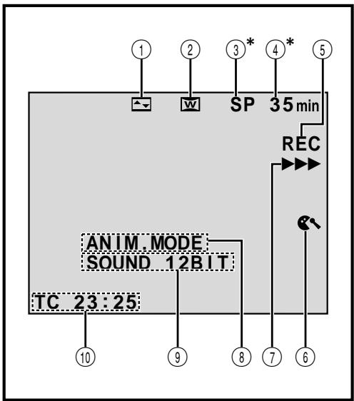
① Displays the selected Fade/Wipe effect.
(1 pg. 34, 35)
② Appears when in the Squeeze, Cinema or PS
Wide mode.
(13 pg. 28)
③ ^ 水 Displays the recording mode (SP or LP).
(pg.11)
④ ^ 水 Displays the tape remaining time.
(1 pg. 16)
⑤ "REC" appears during recording.
- "PAUSE" appears during Record-Standby mode.
(13 pg. 16)
⑥ Appears when the wind cut mode is engaged to
cut down on noise created by wind. (pg. 29)
⑦ Appears while the tape is running.
(13 pg. 16)
⑧ 5S MODE/ANIM. MODE: Displays the 5 second recording mode or Animation recording mode.
(pg. 28, 33)
9 Displays the sound mode for approx. 5 seconds
after turning on the camcorder. (pg. 27)
⑩ Displays the Time Code.
(pg. 21, 29)
- Setting "ON SCREEN" to "SIMPLE" in the Menu Screen removes indications marked with * from the screen (13 pg. 29, 41).
LCD Monitor/Viewfinder Indications During D.S.C. Recording Only
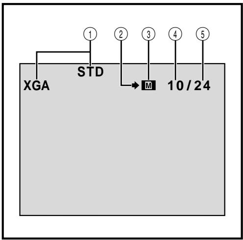
① Displays the Picture Quality/Size mode of the stored image. There are 4 modes available: XGA FINE, XGA STD, VGA FINE and VGA STD (in order of quality). (F) pg. 13)
② Appears and blinks during shooting. (pg. 19)
③ -Appears during shooting.
- Blinks when a MultiMediaCard is not loaded.
(13 pg. 19)
④ Displays the number of images that have already been shot. (13 pg. 19)
⑤ Displays the total number of shots that can be stored, including those already taken.
(13 pg. 19)
These indications also appear during DUAL mode.
LCD Monitor/Viewfinder Indications During Both Video And D.S.C. Recording
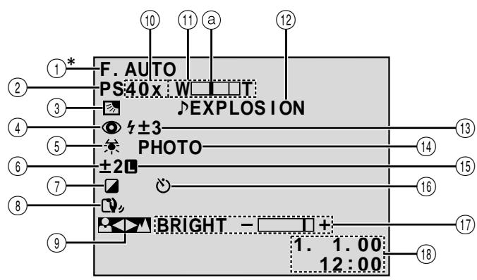
1^* Appears when the Operation switch is set to "A". (pg. 14)
② Displays the shooting mode position. (F pg. 15)
③ Appears when backlight compensation is used. (ppg. 38)
④ Appears when "FLASH" is set to "AUTO" in the Menu Screen. (pg. 30)
⑤ Appears when the white balance is adjusted. (pg. 39)
⑥ Appears when the exposure is adjusted. (F pg. 38)
⑦ Displays the selected Programme AE with special effects. (pp. 36)
8 Appears when Digital Image Stabiliser ("DIS") is engaged. (pg. 28)
9 Appears when the focus is adjusted manually. (F pg. 25)
Approximate zoom ratio: Appears during zooming. (pg. 20)
A:Appears when "GAIN UP" is set to "AUTO"and the shutter speed is automatically adjusted. (pg.27)
⑪ Appears during zooming.
⑧ Zoom level indicator (pg. 20)
⑫ Displays the selected Digital Sound Effect. (pg. 37)
13 Appears when the flash is ready. A number appears next to the indication after adjusting the brightness of the flash. (13 pg. 30, 31)
⑭ Appears when taking a Snapshot. (15 pg. 18, 19)
⑤ Appears when the iris is locked. (pg. 38)
10 Appears during Self-Timer recording. (pg. 32)
⑰ Displays the brightness of the LCD monitor or the viewfinder. (13 pg. 16)
18 Displays the date/time. (pg. 9)
LCD Monitor/Viewfinder Indications During Video Playback
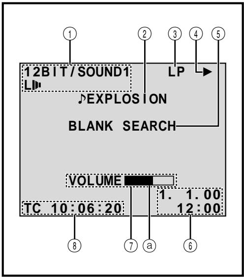
① Displays the sound mode. (13 pg. 41, 42)
② Displays the selected Digital Sound Effect. (13 pg. 37)
③ Displays the tape speed. (pg. 11)
④ Appears while a tape is running.
▶ : Playback
: Fast-Forward/Shuttle search
: Rewind/Shuttle search
:Pause
: Forward slow-motion
: Reverse slow-motion
: Audio Dubbing
Audio Dubbing Pause
⑤ Displays the Blank Search mode. (pg. 43)
Displays the date/time. (13 pg. 41, 42)
⑦ BRIGHT : Displays the brightness of the LCD monitor or the viewfinder. (F pg. 16)
VOLUME: Displays the speaker or headphone volume. (pg. 40)
The level indicator moves.
⑧ Displays the time code. (15 pg. 41, 42)
LCD Monitor/Viewfinder Indications During D.S.C. Playback
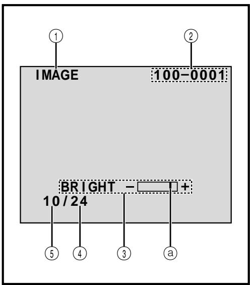
① Displays the type of file (IMAGE/E-MAIL CLIP/ SOUND).
② Displays the directory and file names. (F pg. 45)
③ Displays the brightness of the LCD monitor or the viewfinder. (13 pg. 16)
The level indicator moves.
④ Displays the total number of stored files. (F pg. 45)
⑤ Displays the index number of the file. (F pg. 45)
Warning Indications
| Indications | Function |
| Displays the battery remaining power.Remaining power level: high——→→→ | |
| Remaining power level: exhausted | |
| As the battery power comes close to nil, the battery indicator →blinks.When the battery power is exhausted, power turns off automatically. | |
| Appears when no tape is loaded. (Fpg. 10) | |
| CHECK TAPE'S ERASE PROTECTION SWITCH | Appears when the erase protection tab is set to “SAVE” while the POWER Switch is set to “CAMERA”. (Fpg. 10) |
| HEAD CLEANING REQUIRED USE CLEANING CASSETTE | Appears if dirt is detected on the heads during recording. Use an optional cleaning cassette. (Fpg. 94) |
| CONDENSATION OPERATION PAUSED PLEASE WAIT | Appears if condensation occurs. When this indication is displayed, wait more than 1 hour until condensation disappears. |
| TAPE! | Appears if a tape is not loaded when START/STOP is pressed while the POWER Switch is set to “CAMERA” and the MODE Dial is set to “VIDEO”, “PS” or “DUAL”. |
| TAPE END | Appears when the tape ends during recording or playback. (Fpg. 17) |
| DIFFERENT FORMATTED TAPE | Appears if a tape in another format is loaded. |
| SET DATE/TIME! | Appears when the date/time is not set. (Fpg. 9)Appears when the built-in clock (lithium) battery is discharged and the previously set date/time is erased. (Fpg. 9) |
| A. DUB ERROR! | Appears if Audio Dubbing is attempted on a blank portion of a tape. (Fpg. 76) |
| A. DUB ERROR!<CANNOT DUB ON A LP RECORDED TAPE><CANNOT DUB ON A 16BIT RECORDING><CHECK TAPE'S ERASE PROTECTION SWITCH> | Appears if Audio Dubbing is attempted on a tape recorded in the LP mode. (Fpg. 76)Appears if Audio Dubbing is attempted on a tape recorded in 16-bit audio. (Fpg. 76)Appears if A. DUB (=) on the remote control is pressed when the erase protection tab is set to “SAVE”. (Fpg. 76) |
| MEMORY IS FULL | Appears when the MultiMediaCard's memory is full and shooting is not possible. |
| COPYING Failed | • Appears if dubbing of copyguarded signals is attempted while this camcorder is being used as a recorder (GR-DVX10 only). • Appears in the following cases when dubbing from a tape to a MultiMediaCard (as digital stills or video clips): - when no MultiMediaCard is loaded. - when the MultiMediaCard's memory is full. - when the MultiMediaCard is not formatted. • Appears in the following cases when dubbing still images or sound effects stored in the MultiMediaCard's memory to a tape: - when condensation occurs. - when no tape is loaded. - when the erase protection tab is set to “SAVE”. - when a tape in another format is loaded. - when the tape ends. (CP pg. 64) |
| MEMORY CARD! | Appears if a MultiMediaCard is not loaded when SNAPSHOT is pressed while the POWER Switch is set to “CAMERA” and the MODE Dial is set to “DSC” or “DUAL”。 |
| PLEASE FORMAT | Appears when there is a problem with a MultiMediaCard and its memory is corrupt, or it has not been initialised. Initialise the MultiMediaCard. (CP pg. 50) |
| NO STORED DATA | Appears when the POWER Switch is set to “MEMORY” and there are no files stored in the MultiMediaCard. |
| NO SOUND DATA | Appears if there are no sound files stored in the MultiMediaCard when DIGITAL SOUND is pressed. |
| NO STORED IMAGE | Appears when the POWER switch is set to “MEMORY” and all image files are deleted. |
| NO E-CLIP DATA | Appears when the POWER switch is set to “MEMORY” and all E-clip recording files are deleted. |
| UNSUPPORTED DATA | Appears when a file in a format other than MP3 is selected. |
| E01-E06 UNIT IN SAFEGUARD MODE REMOVE AND REATTACH BATTERY | The error indications (E01-E06) show what type of malfunction has occurred. When an error indication appears, the camcorder turns off automatically. Remove the power supply (battery, etc.) and wait a few minutes for the indication to clear. When it does, you can resume using the camcorder. If the indication remains, consult your nearest JVC dealer. |
General Battery Precautions
If the remote control is not functioning even if it is being operated correctly, the batteries are exhausted. Replace them with fresh ones.
Use only the following batteries: AAA (R03) size x 2 Please make note of the following rules for battery use. When misused, the batteries can leak or explode.
- When replacing batteries, refer to page 66.
- Do not use any different size of batteries from those specified.
- Be sure to install batteries in the correct direction.
- Do not use rechargeable batteries.
- Do not expose the batteries to excessive heat as they can leak or explode.
- Do not dispose of the batteries in a fire.
- Remove the batteries from the unit if it is to be stored for an extended period to avoid battery leakage which can cause malfunctions.
Battery Packs
The supplied battery pack is a lithium-ion battery. Before using the supplied battery pack or an optional battery pack, be sure to read the following cautions:
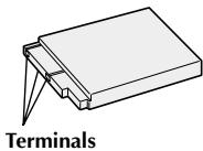
1. To avoid hazards . . .
...do not burn.
...do not short-circuit the terminals.
...do not modify or disassemble.
...do not expose the battery to temperatures exceeding 60^ , as this may cause the battery to overheat, explode or catch fire.
....use only specified chargers.
2. To prevent damage and prolong service life . . .
...do not subject to unnecessary shock.
.... charge in an environment where temperatures are within the tolerances shown in the chart below. This is a chemical reaction type battery—cooler temperatures impede chemical reaction, while warmer temperatures can prevent complete charging.
... store in a cool, dry place. Extended exposure to high temperatures will increase natural discharge and shorten service life.
.... fully charge and then fully discharge the battery every 6 months when storing the battery pack over a long period time.
...remove from charger or powered unit when not in use, as some machines use current even when switched off.
NOTES:
It is normal for the battery pack to be warm after charging, or after use.
Temperature Range Specifications
Charging 10°C to 35°C
Operation 0°C to 40°C
Storage -10oC to 30oC
- Recharging time is based on room temperature of 20^ .
- The lower the temperature, the longer recharging takes.
Cassettes
To properly use and store your cassettes, be sure to read the following cautions:
- During use ...
....make sure the cassette bears the Mini DV mark.
...be aware that recording onto prerecorded tapes automatically erases the previously recorded video and audio signals.
...make sure the cassette is positioned properly when inserting.
...do not load and unload the cassette repeatedly without allowing the tape to run at all. This slackens the tape and can result in damage.
...do not open the front tape cover. This exposes the tape to fingerprints and dust.
- Store cassettes . . .
...away from heaters or other heat sources.
....out of direct sunlight.
....where they won't be subject to unnecessary shock or vibration.
....where they won't be exposed to strong magnetic fields (such as those generated by motors, transformers or magnets).
... vertically, in their original cases.
MultiMediaCards
To properly use and store your MultiMediaCards, be sure to read the following cautions:
- During use ...
...make sure the MultiMediaCard bears the MultiMediaCard mark.
...make sure the MultiMediaCard is positioned properly when inserting.
- While the MultiMediaCard is being accessed (during recording, playback, deletion, initialisation, etc.) ...
...never unload the MultiMediaCard and never turn off the camcorder.
- Store MultiMediaCards . . .
...away from heaters or other heat sources.
....out of direct sunlight.
....where they won't be subject to unnecessary shock or vibration.
....where they won't be exposed to strong magnetic fields (such as those generated by motors, transformers or magnets).
LCD Monitor
- To prevent damage to the LCD monitor, DO NOT . . .
... push it strongly or apply any shocks.
...place the camcorder with the LCD monitor on the bottom.
- To prolong service life . . .
....avoid rubbing it with coarse cloth.
- Be aware of the following phenomena for LCD monitor use.
These are not malfunctions:
- While using the camcorder, the surface around the LCD monitor and/or the back of the LCD monitor may heat up.
- If you leave power on for a long time, the surface around the LCD monitor becomes hot.
Main Unit
- For safety, DO NOT ...
.... open the camcorder's chassis.
...disassemble or modify the unit.
.... short-circuit the terminals of the battery pack. Keep it away from metallic objects when not in use.
... allow inflammables, water or metallic objects to enter the unit.
...remove the battery pack or disconnect the power supply while the power is on.
... leave the battery pack attached when the camcorder is not in use.
- Avoid using the unit . . .
.... in places subject to excessive humidity or dust.
...in places subject to soot or steam such as near a cooking stove.
.... in places subject to excessive shock or vibration.
.....near a television set.
...near appliances generating strong magnetic or electric fields (speakers, broadcasting antennas, etc.).
....in places subject to extremely high (over 40^ or extremely low (under 0^ temperatures.
- DO NOT leave the unit . . .
...in places of over 50^
...in places where humidity is extremely low (below 35% ) or extremely high (above 80% ).
.... in direct sunlight.
...in a closed car in summer.
...near a heater.
4. To protect the unit, DO NOT . . .
....allow it to become wet.
...drop the unit or strike it against hard objects.
...subject it to shock or excessive vibration during transportation.
...keep the lens directed at extremely bright objects for long periods.
...expose the lens to direct sunlight.
...carry it by holding the LCD monitor or the viewfinder.
... swing it excessively when using the hand strap or the grip.
... swing the soft camera case excessively when the camcorder is inside it.
5. Dirty heads can cause the following problems:


- No picture during playback.
- Blocks of noise appear during playback.
- During recording, the Head Clog Warning indicator "×" appears.
In such cases, use an optional cleaning cassette. Insert it and play back. If the cassette is used more than once consecutively, damage to the video heads may result. After the camcorder plays back for about 20 seconds, it stops automatically. Also refer to the cleaning cassette's instructions.
If, after using the cleaning cassette, the problems still exist, consult your nearest JVC dealer.
Mechanical moving parts used to move the video heads and video tape tend to become dirty and worn out over time. In order to maintain a clear picture at all times, periodic check-ups are recommended after using the unit for about 1,000 hours. For periodic check-ups please consult your nearest JVC dealer.
How To Handle A CD-ROM
- Take care not to soil or scratch the mirror surface (opposite to the printed surface). Do not write anything or put a sticker on either the front or back surface. If the CD-ROM gets dirty, gently wipe it with a soft cloth outward from the centre hole using a circular motion.
- Do not use conventional disc cleaners or cleaning spray.
- Do not bend the CD-ROM or touch its mirror surface.
- Do not store your CD-ROM in a dusty, hot or humid environment. Keep it away from direct sunlight.
About moisture condensation . . .
- You have observed that pouring a cold liquid into a glass will cause drops of water to form on the glass' outer surface. This same phenomenon occurs on the head drum of a camcorder when it is moved from a cool place to a warm place, after heating a cold room, under extremely humid conditions or in a place directly subjected to the cool air from an air conditioner.
- Moisture on the head drum can cause severe damage to the video tape, and can lead to internal damage to the camcorder itself.
Serious malfunctioning
If malfunctioning occurs, stop using the unit immediately and consult your local JVC dealer.
The camcorder is a microcomputer-controlled device. External noise and interference (from a TV, a radio, etc.) might prevent it from functioning properly. In such cases, first disconnect its power supply unit (battery pack, AC Power Adapter/Battery Charger, etc.) and wait a few minutes and then re-connect it and proceed as usual from the beginning.
A
AC Power Adapter/Charger pg. 6, 7
Analogue Input 13 pg. 41, 61
Animation 13 pg. 33
Audio Dubbing 17 pg. 76
Auto Date. pg. 29
Auto Focus 13 pg.25
Auto Playback. pg. 45
Auto Shut off pg. 17, 19, 40
B
Backlight Compensation 38
Battery Low. pg. 91
Battery Pack 13 pg.6,7,93
Beep/Tally pg.27
Blank Search pg. 43
Brighten The LCD Monitor. pg. 16
Built-in Clock's Lithium Battery. pg. 9
C
Channels (Left/Right) pg. 42
Charge The Battery Pack. pg. 6
Cinema 1 pg.28
Classic Film 3 pg. 36
Clean The Camcorder. pg. 78
Connections pg. 7, 56-63, 71
D
Darken The LCD Monitor 16
Date/Time Display. pg. 29, 41, 42
Date/Time Settings 13 pg.9
Deleting Files pg.49
Demonstration Mode. pg. 5, 28
Digital Sound Effect pg. 37
Digital Zoom 13 pg. 20, 27
DIS (Digital Image Stabiliser) 13 pg. 28
Dioptre Adjustment 13 pg.8
DPOF (Digital Print Order Format) ... pg. 54
Dual Shooting 24
Dubbing. pg. 60-65
E
E-Mail Clip Recording. pg. 44
Erase Protection. pg. 10
Exposure Control 13 pg. 38
F
Fade-In/Out. pg. 34, 35
Fast-Forward The Tape. pg. 40
5-second recording mode. 13 pg. 33
Flash 3 pg. 30, 31
Frame-By-FramePlayback. pg.40,68
G
Gain Up pg. 27
Grip Adjustment 13 pg.8
1
Icons 13 pg.27-29
Index Playback pg. 47
Index Screen pg. 46
Initialise A MultiMediaCard pg. 50
Iris. pg. 38
Iris Lock 13 pg. 38
J
Journalistic Shooting. pg. 17
L
LCD monitor/Viewfinder
Indications 13 pg.88-92
Load A Tape pg. 10
M
Manual Focus. pg. 25
Menu Screen, CAMERA MENU. pg. 27
Menu Screen, DISPLAY MENU pg. 29, 41
Menu Screen, MANUAL MENU... pg. 28, 29
Menu Screen, MEMORY MENU pg. 48
Menu Screen,VIDEO MENU 13 pg.41
MODE Dial Position. 13 pg. 15
Monotone 13 pg. 36
Motor Drive Mode. 13 pg. 18
MultiMediaCard. pg. 12, 94
0
Operation Switch Position 14
P
Picture Quality/Size Mode 13 pg. 13
Picture Wipe/Dissolve. 13 pg. 34, 35
Playback Special Effects pg. 69
Playback Zoom pg.68
POWER Switch Position pg. 14
Print Frame Deletion. pg. 52, 53
Printer 59
Programme AE With Special Effects... pg. 36
Progressive Mode 22, 23
Progressive Wide. pg. 28
Protecting Files pg. 48
Provided Accessories. pg. 4
R
Random Assemble Editing... pg. 70-75
Record-Standby pg. 16
Recording Mode. pg. 11
Red-Eye Reduction 13 pg. 30
Remote Control pg. 66
Rewind The Tape. pg. 40
s
Self-Recording pg. 17
Self-Timer pg. 32
Sepia. pg. 36
Set Remote Control/VCR Code 13 pg. 70
Shooting Mode, DUAL pg. 15
Shooting Mode, DSC 13 pg. 15
Shuttle Search. pg. 40
Shutter Speed 13 pg. 36
Slow-MotionPlayback. pg.68
Slow Shutter pg. 36
Snapshot 18, 19, 24
Snapshot Mode pg. 18, 19
Sound Mode. pg. 27, 41, 42
Speaker Volume pg. 40
Specifications 13 pg.98,99
Squeeze 13 pg.28
Still Playback pg. 40
Strobe 13 pg. 36
Superimposing A Print Frame. pg. 51
T
Tele Macro 13 pg.28
Time Code. pg. 21, 29, 41, 42
Tripod Mounting. pg. 8
Twilight 3 pg. 36
U
Unload A Tape 13 pg. 10
V
Video Echo 13 pg. 36
W
White Balance. pg. 39
Wide Mode 1 pg.28
Wind Cut pg. 29
Wipe In/Out pg. 34, 35
Z
Zooming 13 pg. 20
Camcorder
For General
| Power supply | : DC 6.3 V--- (Using AC Power Adapter/Charger) DC 7.2 V--- (Using battery pack) |
| Power consumption | |
| LCD monitor off, viewfinder on | |
| GR-DVX10 | : Approx. 4.9 W |
| GR-DVX9 | : Approx. 4.6 W |
| LCD monitor on, viewfinder off | |
| GR-DVX10 | : Approx. 5.8 W |
| GR-DVX9 | : Approx. 5.5 W |
| Dimensions (W x H x D) | : 51 mm x 125 mm x 97 mm (with the LCD monitor closed and the viewfinder pushed back in) |
| Weight | : Approx. 515 g (without cassette, MultiMediaCard and battery) Approx. 590 g (incl. cassette, MultiMediaCard and battery) |
| Operating temperature | : 0°C to 40°C |
| Operating humidity | : 35% to 80% |
| Storage temperature | : -20°C to 50°C |
| Pickup | : 1/4" CCD (Progressive Scan) |
| Lens | : F 1.8, f = 3.8 mm to 38 mm, 10:1 power zoom lens |
| Filter diameter | :ø27 mm |
| LCD monitor | : 2.5" diagonally measured, LCD panel/TFT active matrix system |
| Viewfinder | : Electronic viewfinder with 0.44" colour LCD |
| Speaker | : Monaural |
| For Digital Video Camera | |
| Format | : DV format (SD mode) |
| Signal format | : PAL standard |
| Recording/Playback format | : Video: Digital component recording : Audio: PCM digital recording, 32 kHz 4-channel (12-bit), 48 kHz 2-channel (16-bit) |
| Cassette | : Mini DV cassette |
| Tape speed | : SP: 18.8 mm/s LP: 12.5 mm/s |
| Maximum recording time (using 80 min. cassette) | : SP: 80 min. LP: 120 min. |
| For Digital Still Camera | |
| Storage media | : MultiMediaCard |
| Compression system | : JPEG (compatible) |
| File size | : 2 modes (XGA: 1024 x 768 pixels/VGA: 640 x 480 pixels) |
| Picture quality | : 2 modes (FINE/STANDARD) |
| Approximate number of storable images (with the provided MultiMediaCard [8 MB], with Sound Effects pre-stored) | |
| FINE | : 46 (VGA), 21 (XGA) |
| STANDARD | : 133 (VGA), 64 (XGA) |
| (with an optional MultiMediaCard [4 MB]) | |
| FINE | : 26 (VGA), 12 (XGA) |
| STANDARD | : 76 (VGA), 36 (XGA) |
| (with an optional MultiMediaCard [8 MB]) | |
| FINE | : 54 (VGA), 24 (XGA) |
| STANDARD | : 155 (VGA), 75 (XGA) |
For Connectors
| Video output | : 1 V (p-p), 75 Ω, analogue |
| Audio output | : 300 mV (rms), 1 kΩ, analogue, stereo |
| DV | |
| Input/output (GR-DVX10 only) | : 4-pin, IEEE 1394 compliant |
| Output (GR-DVX9 only) | : 4-pin, IEEE 1394 compliant |
| Headphone output | : Ø3.5 mm, stereo |
AC Power Adapter/Charger AA-V51EG or AA-V51EK
| Power requirement | : AC 110 V to 240 V~, 50 Hz/60 Hz |
| Power consumption | : 23 W |
| Output | |
| Charge | : DC 7.2 V---, 0.77 A |
| VTR | : DC 6.3 V---, 1.8 A |
| Dimensions (W x H x D) | : 68 mm x 45 mm x 110 mm |
| Weight | |
| AA-V51EG | : Approx. 255 g |
| AA-V51EK | : Approx. 330 g |
Docking Station CU-V502E
For General
| Dimensions (W x H x D) | : 55 mm x 36 mm x 107 mm |
| Weight | : Approx. 89.9 g |
For Connectors
| S | |
| Output | : Y : 1 V (p-p), 75 Ω, analogue C : 0.29 V (p-p), 75 Ω, analogue |
| Input (GR-DVX10 only) | : Y : 0.8 V (p-p) - 1.2 V (p-p), 75 Ω, analogue C : 0.2 V (p-p) - 0.4 V (p-p), 75 Ω, analogue |
| VIDEO | |
| Video output | : 1 V (p-p), 75 Ω, analogue |
| Video input (GR-DVX10 only) | : 0.8 V (p-p) - 1.2 V (p-p), 75 Ω, analogue |
| AUDIO | |
| Audio output | : 300 mV (rms), 1 kΩ, analogue, stereo |
| Audio input (GR-DVX10 only) | : 300 mV (rms), 50 kΩ, analogue, stereo |
| JLIP (EDIT) | : Ø3.5 mm, 4-pole, mini-head jack (compatible) |
| PC (DIGITAL STILL) | : Ø2.5 mm, 3-pole |
| External microphone input | : 506 μV (rms), high impedance unbalanced |
| PRINTER | : For an optional video printer equipped with connector |
Specifications shown are for SP mode unless otherwise indicated. E & O.E. Design and specifications subject to change without notice.
JVC
VICTOR COMPANY OF JAPAN, LIMITED