
717411 - TV Antenna ONE FOR ALL - Free user manual and instructions
Find the device manual for free 717411 ONE FOR ALL in PDF.

| Product Type | TV Antenna |
| Brand | One For All |
| Model | 717411 |
| Mounting Type | Wall or pole mount (pole not included) |
| Reception | Digital TV signals (ATSC) |
| Frequency Support | UHF/VHF |
| Amplified | Yes, with power inserter |
| Power Source | USB (5V) from TV or included power adapter |
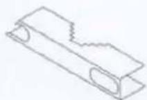
| Coaxial Cable Included | 30 ft. (9.1 m) with plastic boot |
| Connector Type | Coaxial F-type |
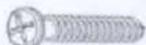
| Includes | Antenna, mounting bracket, screws, USB power adapter, coaxial cable |
| Warranty | 1 Year Limited Warranty |
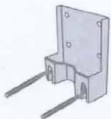
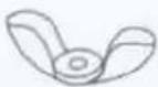
| Mounting Hardware | Bracket, U-bolt, wing nuts, screws, wall plugs |
| Grounding Requirement | Recommended for outdoor/attic installation (per NEC Article 810) |
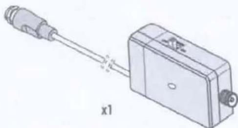
| Power Inserter | Includes ON/OFF switch |
Frequently Asked Questions - 717411 ONE FOR ALL
User questions about 717411 ONE FOR ALL
0 question about this device. Answer the ones you know or ask your own.
Ask a new question about this device
Download the instructions for your TV Antenna in PDF format for free! Find your manual 717411 - ONE FOR ALL and take your electronic device back in hand. On this page are published all the documents necessary for the use of your device. 717411 by ONE FOR ALL.
USER MANUAL 717411 ONE FOR ALL
natural_image
Line drawing of a rectangular electronic device with a flat top and a vertical slot, no text or symbols present.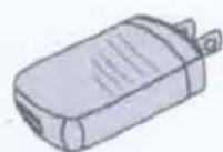
x1
x1
natural_image
Diagram of a connector with a cable and housing, labeled 'x1' (no text or symbols on the diagram itself)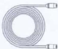
natural_image
Coiled industrial hose with two connectors (no text or symbols visible)Cable 30 ft.
natural_image
3D rendering of a mechanical component with two metal rods and mounting holes (no text or symbols)x1
x1

(x2)
(x2)

(x2)
(x4)
(x2)

(x4)
1
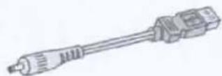
FIRST connect the USB cable to the power adapter. Put the power adaptor in any standard 120V wall outlet. Alternatively you can plug the USB cable in one of your USB ports on the side or back of your TV (if available).
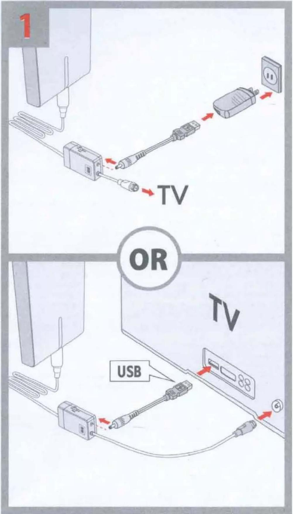
2 Now connect the coaxial cable with the additional plastic boot (cap) at the end to the antenna itself.
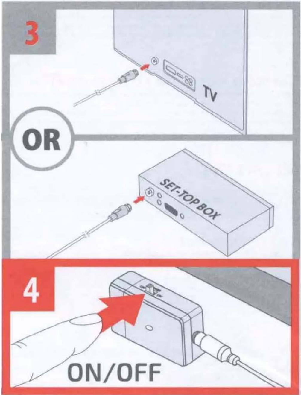
3 Then connect the coaxial cable at the other end to the ANTENNA IN connector at the back of the TV or set-top box.
4 Turn ON the switch on the power inserter.
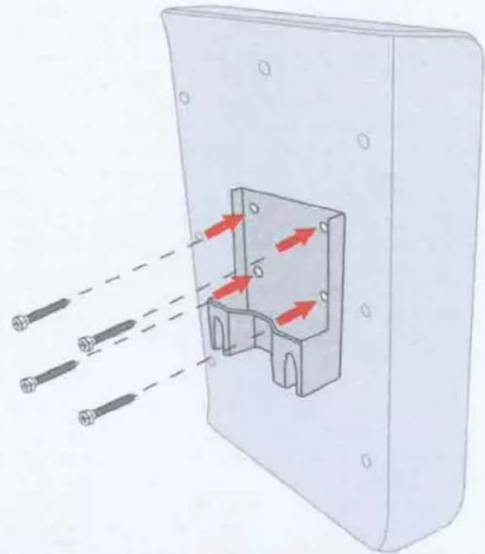
5 First secure the mounting bracket to the antenna by using the four screws included in the plastic bag with mounting materials.
6 Decide how you would like to mount the antenna: Wall mount or pole mount (pole not included in packaging)
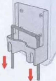
If you choose to wall mount the antenna, then position the mounting bracket (flat surface to the wall) as high as possible and drill two holes (distance between holes 58 mm) and put the wall plugs in the holes. After that you can put the screws in. Do not fully screw in but leave 3-4 mm sticking out. Then hang the bracket with antenna attached over the screws.
2
natural_image
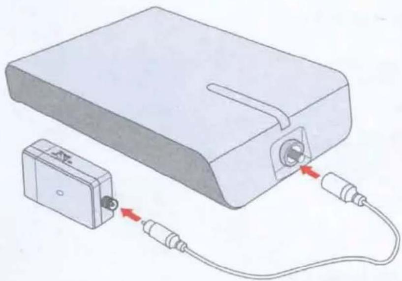
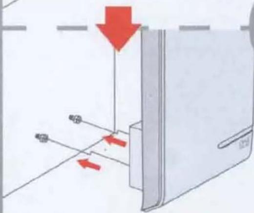
Illustration of a device connected to a battery via cable, showing internal components and red directional arrows (no text or symbols)If you choose to mount it to a pole first attach the U-shaped screw to the bracket. Then attach the clipper to the two sides of the U-shaped screw. Make sure the pole is in between the bracket and the clipper. Now you can screw the wingnuts onto the both ends of the U-shaped screw.
We suggest that you first finalize this setup before drilling holes, since you might need to re-position the antenna for best reception. Position the antenna as high as possible and facing the direction of the TV towers for best reception. If you are not sure in which direction your TV towers are, please check www.channelchecker.com and it will tell you in 3 simple steps.
5
natural_image
Diagram of a device with three sensors emitting red arrows through a housing (no text or symbols)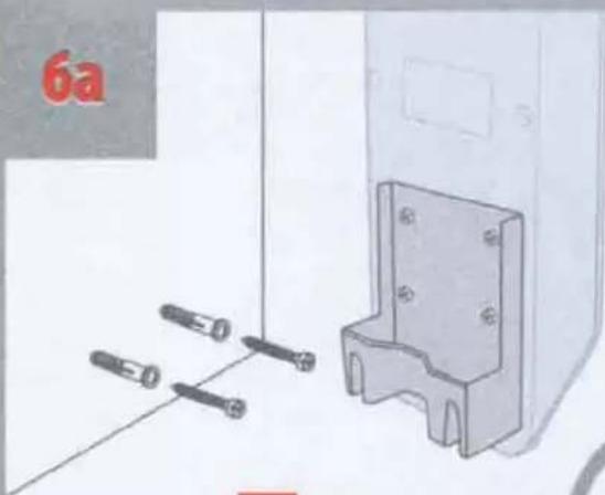
natural_image
Illustration of a mechanical bracket with four screws and a separate panel, no text or symbols present6b

natural_image
Mechanical component diagram showing a bracket with two vertical supports and red arrows indicating downward force or movement (no text or symbols present)
natural_image
Diagram showing a device with red arrows indicating movement or force, no readable text or symbols present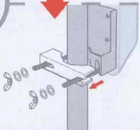
natural_image
Mechanical assembly diagram showing a clamping mechanism with rotating parts and directional arrows (no text or symbols)Now you can perform a channel scan on your TV. Set the tuner mode of the TV to ANTENNA first, then choose CHANNEL SCAN (may be called AUTO PROGRAM, AUTO TUNING, AUTO SCAN or CHANNEL SEARCH in the setup menu of your TV).
If the number of channels or the quality is poor, please change the antenna's position and go to step ☐ OR ☑ and RE-SCAN on your TV.
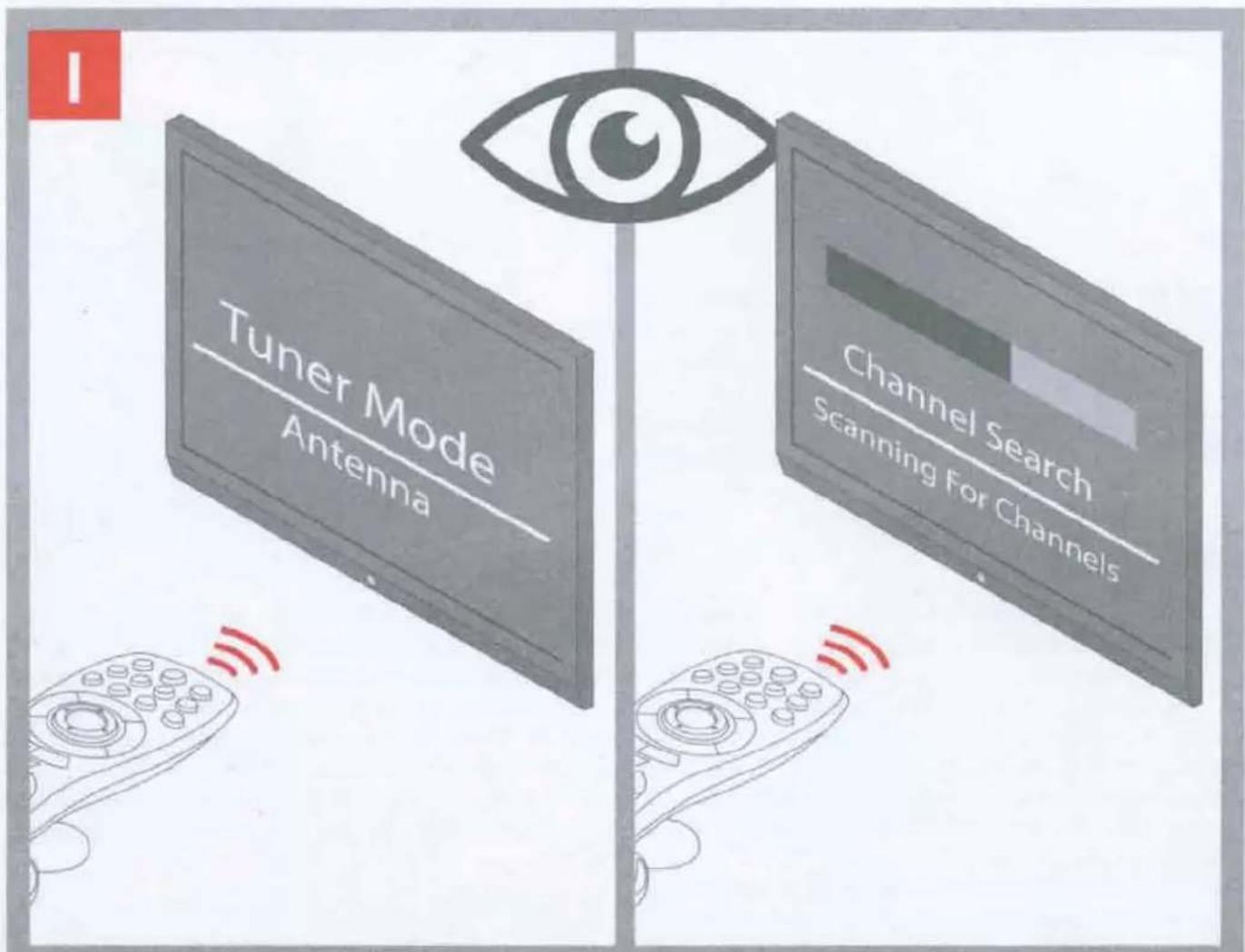
For detailed instructions on how to perform a channel scan, please see the manual provided with your TV.
natural_image
Two isometric house diagrams with a red arrow indicating transformation (no text or symbols)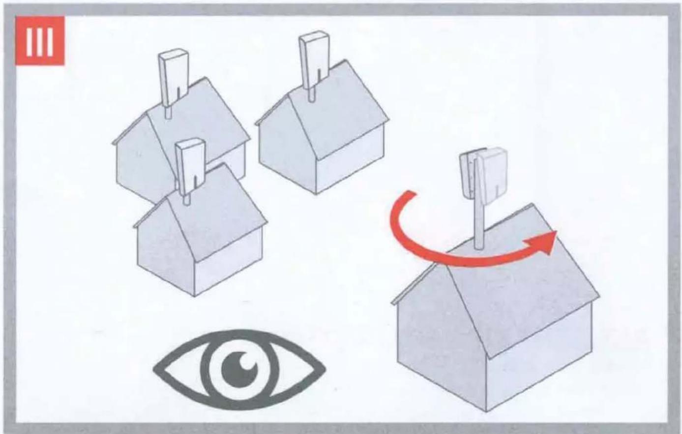
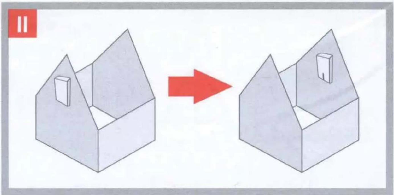
IMPORTANT!
Remember to perform a RE-SCAN on your TV. Whenever you re-position or rotate the antenna you have to perform a CHANNEL SCAN on your TV.

¡IMPORTANTE!
Before returning this product please call us for support
natural_image
Simple line drawing of a rectangular box with a vertical slot, no text or symbols presentBefore returning this product please call us for support
Customer Support:
855-823-3422
(toll free)
OFA warranty/terms & conditions: 855-569-6595 (toll free)
www.oneforall.com
Imported into the US by:
Universal Electronics Inc.
UEI Technical Support Services.
Suite 301
26250 Euclid Ave.
Euclid, OH 44132
One For All is a registered trademark of UEl
Made in China, Hecho en China
Grounding your OFA Antenna
When installing your attic / outdoor antenna on your rooftop or outdoors, it is recommended that you follow National and/or Local Electrical codes to properly ground your antenna. This will reduce the chances of your antenna or mast being struck by lightning. Please consult National Electrical Code, Article 810, or contact a local electrician for details and/or assistance.
• Make sure there is another person present (on the ground) while installing the attic / outdoor Antenna.
- DO NOT attempt to mount the antenna on a windy, rainy or snowy day.
MOUNT THE ANTENNA AT LEAST 20 FT. FROM ALL POWER LINES OR UTILITY POLES.
POWER LINE WARNING
If you intend to mount the attic / outdoor Antenna on a rooftop, make sure to mount it at least 20 ft. away from any power lines or utility poles.
- Avoid metal surfaces
- Position the antenna as high as possible
ESPAÑOL
1 Year Limited Warranty against defects in material and workmanship can be found at www.oneforall.com/warranty, or you may request a hard copy by calling 855-569-6595, or via mail to UEI Technical Support Service, Suite 301, 26250 Euclid Ave., Euclid, OH 44132.
Please include your full name, product information, and contact information in your request communication.
LIMITED WARRANTY
Warranty: Universal Electronics Inc. warrants this product to be free from defects in material and workmanship for a period of one year from the date of purchase. This warranty does not apply to damage caused by shipping or handling, or damage caused by accident, abuse, misuse, misapplication, ordinary wear, improper maintenance, failure to follow instructions or as a result of any unauthorized modifications. The foregoing warranty shall apply only to the original buyer, and is and shall be in lieu of any and all other warranties, whether expressed or implied and of all other obligations or liabilities on the part of Universal Electronics Inc. neither assumes responsibility for, nor authorizes any other person purporting to act on its behalf to modify or to change this warranty, nor to assume for it any other warranty or liability concerning this product. The maximum liability for Universal Electronics Inc. under all circumstances for any warranty issue shall be limited to a replacement of the defective product. It is recommended that the customer check their equipment on a regular basis for proper operation.
Remedies: Your exclusive remedy under this Limited Warranty is that Universal Electronics Inc., at its option, will repair or replace, without charge for parts and/or labor, the product found to be defective.
Service Procedure: To obtain warranty service, visit www.oneforall.com/warranty and complete the form with your full name, contact information, product serial number, and description of the issue along with a legible copy/image of your sales receipt showing date of purchase.
Disclaimer: THE FOREGOING LIMITED WARRANTY IS THE SOLE AND EXCLUSIVE WARRANTY BY UNIVERSAL ELECTRONICS INC. WITH RESPECT TO THE PRODUCTS. THERE ARE NO OTHER REPRESENTATIONS OR WARRANTIES, EXPRESS OR IMPLIED, EXCEPT AS REQUIRED BY APPLICABLE LAW. ANY IMPLIED WARRANTIES REQUIRED BY LAW ARE LIMITED IN DURATION TO WARRANTY PERIOD PROVIDED HEREIN. SOME STATES DO NOT ALLOW LIMITATIONS ON HOW LONG AN IMPLIED WARRANTY LASTS, SO THE ABOVE LIMITATIONS MAY NOT APPLY TO YOU.
IN NO EVENT SHALL UNIVERSAL ELECTRONICS INC. OR ANY OF ITS AFFILIATES BE LIABLE FOR ANY INCIDENTAL, SPECIAL, INDIRECT, CONSEQUENTIAL, OR MULTIPLE DAMAGES, INCLUDING BUT NOT LIMITED TO, LOST PROFITS, LOST OR DAMAGE TO SOFTWARE OR DATA, OR DAMAGE TO EQUIPMENT ARISING OUT OF THE USE OF ANY PRODUCT, EVEN IF ADVISED OF THE POSSIBILITY OF SUCH DAMAGES. THIS STANDARD WARRANTY GIVES YOU SPECIFIC LEGAL RIGHTS, AND YOU MAY ALSO HAVE OTHER RIGHTS, WHICH MAY VARY FROM STATE TO STATE. SOME STATES DO NOT ALLOW THE EXCLUSION OR LIMITATION OF INCIDENTAL OR CONSEQUENTIAL DAMAGE, SO THE ABOVE LIMITATIONS MAY NOT APPLY TO YOU.
Reception quality and the numbers of channels received are dependent on multiple factors like distance from TV broadcast tower, broadcast power, line of sight, terrain, metal construction materials and other environmental factors.
LEGAL NOTICES
FCC STATEMENT:
This equipment has been tested and found to comply with the limits for a Class B digital device, pursuant to part 15 of the FCC Rules. These limits are designed to provide reasonable protection against harmful interference in a residential installation. This equipment generates, uses and can radiate radio frequency energy and, if not installed and used in accordance with the instructions, may cause harmful interference to radio communications. However, there is no guarantee that interference will not occur in a particular installation. If this equipment does cause harmful interference to radio or television reception, which can be determined by turning the equipment off and on, the user is encouraged to try to correct the interference by one or more of the following measures:
- Reorient or relocate the receiving antenna.
- Increase the separation between the equipment and receiver.
- Connect the equipment into an outlet on a circuit different from that to which the receiver is connected.
- Consult the dealer or an experienced radio/TV technician for help.
This device complies with part 15 of the FCC Rules. Operation is subject to the following two conditions: (1) This device may not cause harmful interference, and (2) this device must accept any interference received, including interference that may cause undesired operation.
Caution: Changes or modifications not expressly approved by the party responsible for compliance could void the user's authority to operate the equipment.
ESPAÑOL
UEI Technical Support Service, Suite 301, 26250 Euclid Ave., Euclid, OH 44132.