
TX 42 - Screen AG Neovo - Free user manual and instructions
Find the device manual for free TX 42 AG Neovo in PDF.


User questions about TX 42 AG Neovo
0 question about this device. Answer the ones you know or ask your own.
Ask a new question about this device
Download the instructions for your Screen in PDF format for free! Find your manual TX 42 - AG Neovo and take your electronic device back in hand. On this page are published all the documents necessary for the use of your device. TX 42 by AG Neovo.
USER MANUAL TX 42 AG Neovo
Safety warnings and precautions.... 5
Important safety instructions 7
Notes on the LCD panel of this display.... 7
Safety notice for remote control 8
Battery safety notice 8
Package contents 10
Optional accessory 10
Setting up the display.... 11
Mounting the display 11
Parts of the display and their functions .... 13
Front/Rear panel 13
Input/output terminals 15
Remote control 17
Using the remote control.... 18
Connection.... 19
Connecting audio/video signals 19
Connecting power 26
Using the Touch Screen (for Touch Model Only) 27
Calibrating the Touch Screen (for Touch Model Only) 32
Important Instructions for Using the Touch Screen (for Touch Model Only) 32
Basic operations 33
Turning the display on or off 33
Locking/unlocking the controls.... 33
Switching input signals 33
Adjusting audio volume level 33
Network connection 34
Connecting to a LAN 34
Controlling the display 34
The OSD (On-Screen Display) menu 35
OSD menu overview 35
Operations in the OSD menu.... 37
Picture menu 38
Table of Contents4
Sound menu 39
Screen menu 40
Setting menu 43
Product information.... 46
Specifications 46
Dimensions 48
Supported input signal resolution.... 50
Supported PAP input signal combination 52
Troubleshooting 53
Safety warnings and precautions


CAUTION: TO REDUCE THE RISK OF ELECTRIC SHOCK, DO NOT REMOVE COVER (OR BACK). NO USER-SERVICEABLE PARTS INSIDE. REFER SERVICING TO QUALIFIED SERVICE PERSONNEL.
The lightning flash with arrowhead symbol, within an equilateral triangle, is intended to alert the user to the presence of uninsulated "dangerous voltage" within the product's enclosure that may be of sufficient magnitude to constitute a risk of electric shock to persons.

The exclamation point within an equilateral triangle is intended to alert the user to the presence of important operating and maintenance (servicing) instructions in the literature accompanying the appliance.
THIS EQUIPMENT MUST BE GROUNDED
To ensure safe operation, the three-pin plug must be inserted only into a standard three-pin power outlet which is effectively grounded through normal household wiring. Extension cords used with the equipment must have three cores and be correctly wired to provide connection to the ground. Wrongly wired extension cords are a major cause of fatalities.
The fact that the equipment operates satisfactorily does not imply that the power outlet is grounded or that the installation is completely safe. For your safety, if you are in any doubt about the effective grounding of the power outlet, please consult a qualified electrician.
- The mains plug of the power supply cord shall remain readily operable. The AC receptacle (mains socket outlet) shall be installed near the equipment and shall be easily accessible. To completely disconnect this equipment from the AC mains, disconnect the power cord plug from the AC receptacle.
- Do not place this display on an uneven, sloping or unstable surface (such as a trolley) where it may fall and cause damage to itself or others.
- Do not place this display near water, like a spa or pool, or in a position which will allow the splashing or spraying of water onto the display, like in front of an open window where rain water may enter.
- Do not install this display in a confined space without proper ventilation and air circulation, such as in a closed cabinet. Allow proper space around the display for dissipating heat inside. Do not block any openings and vents on the display. Overheating may result in hazards and electric shock.
• Installation of this display should only be performed by a qualified technician. Failure to install this display properly may cause injuries and damages to the personnels and the display itself. Check the installation regularly and maintain the display periodically to ensure the best working condition. - Use only the accessories approved or recommended by the manufacturer to mount this display. Using wrong or unsuitable accessories may cause the display to fall and result in serious personal injuries. Make sure that the surface and fixing points are strong enough to sustain the weight of the display.
- To reduce the risk of electric shock, do not remove covers. No user serviceable parts inside. Refer servicing to qualified service personnel.
- To prevent personal injuries, mounting the display or installing desktop stands is required before use.
Important safety instructions
- Read these instructions.
- Keep these instructions.
- Heed all warnings.
- Follow all instructions.
- Do not use this apparatus near water.
- Clean only with dry cloth.
-
Do not block any ventilation openings. Install in accordance with the manufacturer's instructions.
-
Do not install near any heat sources such as radiators, heat registers, stoves, or other apparatus (including amplifiers) that produce heat.
-
Do not defeat the safety purpose of the polarized or grounding-type plug. A polarized plug has two blades with one wider than the other. A grounding-type plug has two blades and a third grounding prong. The wide blade or the third prong are provided for your safety. If the provided plug does not fit into your outlet, consult an electrician for replacement of the obsolete outlet.
-
Protect the power cord from being walked on or pinched particularly at plugs, convenience receptacles, and the point where they exit from the apparatus.
-
Only use attachments/accessories specified by the manufacturer.
-
Use only with the cart, stand, tripod, bracket, or table specified by the manufacturer, or sold with the apparatus. When a cart is used, use caution when moving the cart/apparatus combination to avoid injury from tip-over.
-
Unplug this apparatus during lightning storms or when unused for long periods of time.
-
Refer all servicing to qualified service personnel. Servicing is required when the apparatus has been damaged in any way, such as power-supply cord or plug is damaged, liquid has been spilled or objects have fallen into the apparatus, the apparatus has been exposed to rain or moisture, does not operate normally, or has been dropped.

Notes on the LCD panel of this display
- The Liquid Crystal Display (LCD) panel of this display has a very thin protective layer of glass which is liable to marking or scratching, and cracking if struck or pressured. The liquid crystal substrate is also liable to damage under excessive force or extreme temperatures. Please handle with care.
- The response time and brightness of the LCD panel may vary with the ambient temperature.
- Avoid placing the display in direct sun or where direct sun or spot lighting will shine onto the LCD panel, as the heat may damage the panel and the external casing of the display, and the bright light will make viewing the display more difficult than necessary.
- The LCD panel consists of individual pixels to display images and is manufactured according to the design specifications. While 99.9% of these pixels work normally, 0.01% of the pixels may remain constantly lit (in red, blue
or green) or unlit. This is a technical limitation of the LCD technology and is not a defect.
- LCD screens, like plasma (PDP) and conventional CRT (Cathode Ray Tube) screens, are also susceptible to 'screen burn-in' or 'image retention' which can be found on the screen as visible fixed lines and shades. To avoid such damage to the screen, avoid displaying still images (like On-Screen Display menus, TV station logos, fixed/inactive text or icons) for more than two hours. Change the aspect ratio from time to time. Fill the entire screen with the image and eliminate the black bars whenever possible. Avoid displaying images in 4:3 aspect ratio over a long period of time, otherwise there may be visible burn marks on the screen as two vertical lines.
- Note: Under certain circumstances, condensation may occur on the inner side of the cover glass, it's a natural phenomenon and will not affect the operation of the display. This condensation will usually disappear after around 2 hours of normal operation.
Safety notice for remote control
- Do not put the remote control in the direct heat, humidity, and avoid fire.
- Do not drop the remote control.
- Do not expose the remote control to water or moisture. Failure to do so could result in malfunction.
- Confirm there is no object between the remote control and the remote sensor of the product.
- When the remote control will not be used for an extended period, remove the batteries.
Battery safety notice
The use of the wrong type of batteries may cause chemical leaks or explosion. Please note the following:
- Always ensure that the batteries are inserted with the positive and negative terminals in the correct direction as shown in the battery compartment.
- Different types of batteries have different characteristics. Do not mix different types.
- Do not mix old and new batteries. Mixing old and new batteries will shorten battery life or cause chemical leaks from the old batteries.
- When batteries fail to function, replace them immediately.
- Chemicals which leak from batteries may cause skin irritation. If any chemical matter seeps out of the batteries, wipe it up immediately using a dry cloth, and replace the batteries as soon as possible.
- Due to varying storage conditions, the battery life for the batteries included with your product may be shortened. Replace them within 3 months or as soon as you can after initial use.
- There may be local restrictions on the disposal or recycling of batteries. Consult your local regulations or waste disposal provider.
Package contents
Open the sales package and check the contents. If any item is missing or damaged, please contact your dealer immediately.

natural_image
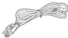
Blank white rectangle with a thin gray border (no text or symbols)LCD display Power cord
natural_image
Line drawing of a coiled cable with a terminal plug (no text or symbols)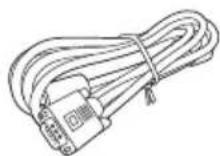
D-Sub (15-pin) cable
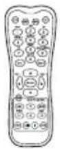
Remote control
natural_image
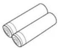
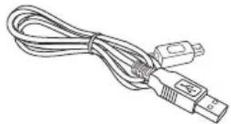
Line drawing of a USB cable with connector port (no text or symbols)AAA batteries CD USB cable

- The type of power cord supplied may differ from that illustrated depending on your region of purchase.
- Before discarding the package, check that you haven't left any accessories inside the box.
- Dispose of packaging materials wisely. You can recycle the cardboard carton. Consider storing the package (if possible) for future transport of the display.
- Do not leave plastic bags within reach of young children or babies.
Optional accessory
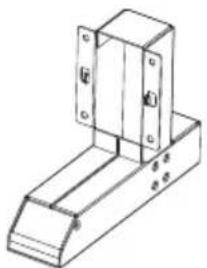
In addition to the items that come with the standard package, the following optional accessory is also available separately:
natural_image
Technical line drawing of a mechanical bracket or mounting structure (no text or symbols)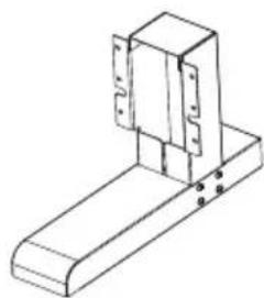
natural_image
Isometric line drawing of a mechanical bracket or mounting base with mounting holes (no text or symbols)TX-32 TX-42
Desktop stand
Setting up the display
Mounting the display
You can install the display on a vertical surface with a suitable wall mounting bracket or on a horizontal surface with the optional desktop stands. Please pay attention to the following notes during installation:
- This display should be installed by at least two adult persons. Attempting to install this display by only one person may result in danger and injuries.
- Refer the installation to qualified technicians. Improper installation may cause the display to fall or malfunction.
Installing the display on a wall
- Place a clean, dry and lint-free cloth on a flat, horizontal and object-free surface. Make sure that the size of the cloth is larger than the display.
- Gently lay the display on the cloth with the LCD screen facing down.
- Remove the desktop stands from the display if installed.
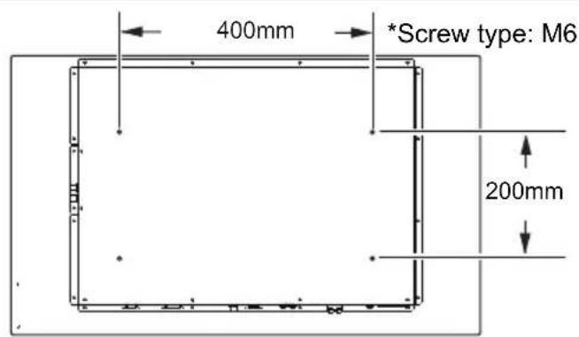
- Identify the wall mounting screw holes on the back of the display as shown in the illustration.
text_image
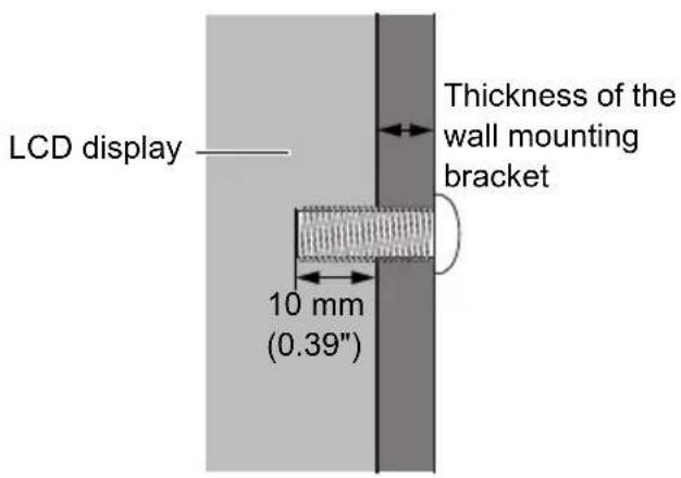
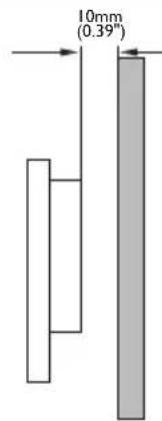
400mm *Screw type: M6 200mm- Install the wall mounting bracket on the display and attach the display to the wall according to the mounting bracket's instructions. The length of the screw should exceed the thickness of the wall mounting bracket by at least 10 mm. Make sure that all screws are tightened and secured properly. (Recommended torque: 470 - 635N·cm). The mounting means should be strong enough to bear the weight of the display.
text_image
LCD display Thickness of the wall mounting bracket 10 mm (0.39")
- To maintain proper ventilation, keep at least 10 mm of clear space from the back cover of the display to the wall.
- Please consult a professional technician for wall mount installations. The manufacturer accepts no liability for installations not performed by a professional technician.
- The AC IN/OUT socket should be on top of connectors when rotating your display.
text_image
10mm (0.39"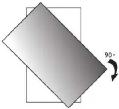
natural_image
Geometric diagram showing a tilted rectangle with an arrow indicating 90° rotation (no text or symbols)Installing the optional desktop stands
- Place a clean, dry and lint-free cloth on a flat, horizontal and object-free surface. Make sure that the size of the cloth is larger than the display.
-
Gently lay the display on the cloth with the LCD screen facing down.
-
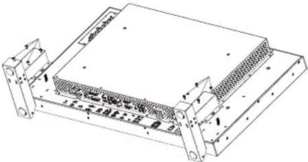
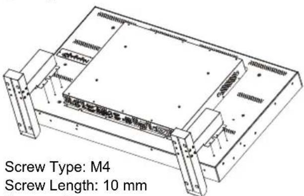
Place the desktop stands on the display as illustrated.
-
Use the screws and a suitable screwdriver to secure the stands on the display.
(TX-32)
natural_image
Technical line drawing of a mechanical or electronic component with mounting brackets and internal channels (no text or symbols)(TX-42)
text_image
Screw Type: M4 Screw Length: 10 mmScrew Type: M4 Screw Length: 10 mm Torque: 10
Parts of the display and their functions Front/Rear panel
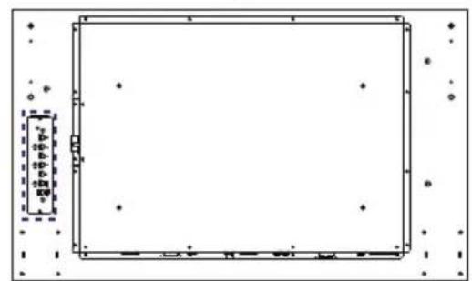
natural_image
Empty rectangular frame with scattered dots and dashed border, no text or symbols present
natural_image
Pure geometric diagram with a rectangle and scattered dots, no text or symbols present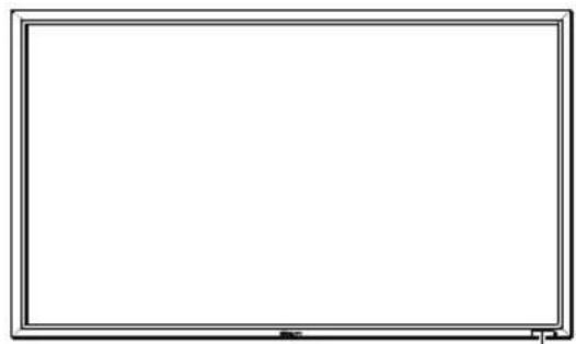
natural_image
Blank whiteboard frame with a thin border (no text or symbols)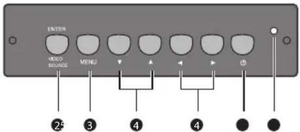
text_image
ENTER VIDEO SOURCE MENU ② ③ ④ ④ ●1
No. Name Description
1
Remote control sensor / Ambient light sensor / Power indicator
- Receives command signals from the remote control.
- Detects ambient lighting conditions around the display and adjusts screen brightness automatically when the Ambient Light Sensor function is activated.
-
Indicates the operating status of the display:
-
Lights up green when the power is turned on.
- Lights up red when the display is turned off.
- Lights up red when the display is in Power Save High mode.
- Flashes red when the display is in Power Save Low mode.
- Off when the main power is turned off.
2
ENTER/VIDEO SOURCE
- Selects a video source.
- Confirms your selection or enters a submenu in the On-Screen Display (OSD) menu.
3
MENU Opens or closes the OSD menu.
4

- Scrolls through settings and options in the OSD menu.
- ◀ / ▶: Hot keys for audio volume adjustment.
5
Power button Turns the display on or off.
6
Power indicator Indicates the power status of the display:
- Lights up green when the power is turned on.
- Lights up red when the display is turned off.
- Lights up red when the display is in Power Save High mode.
- Flashes red when the display is in Power Save Low mode.
- Off when the main power is turned off.
Input/output terminals
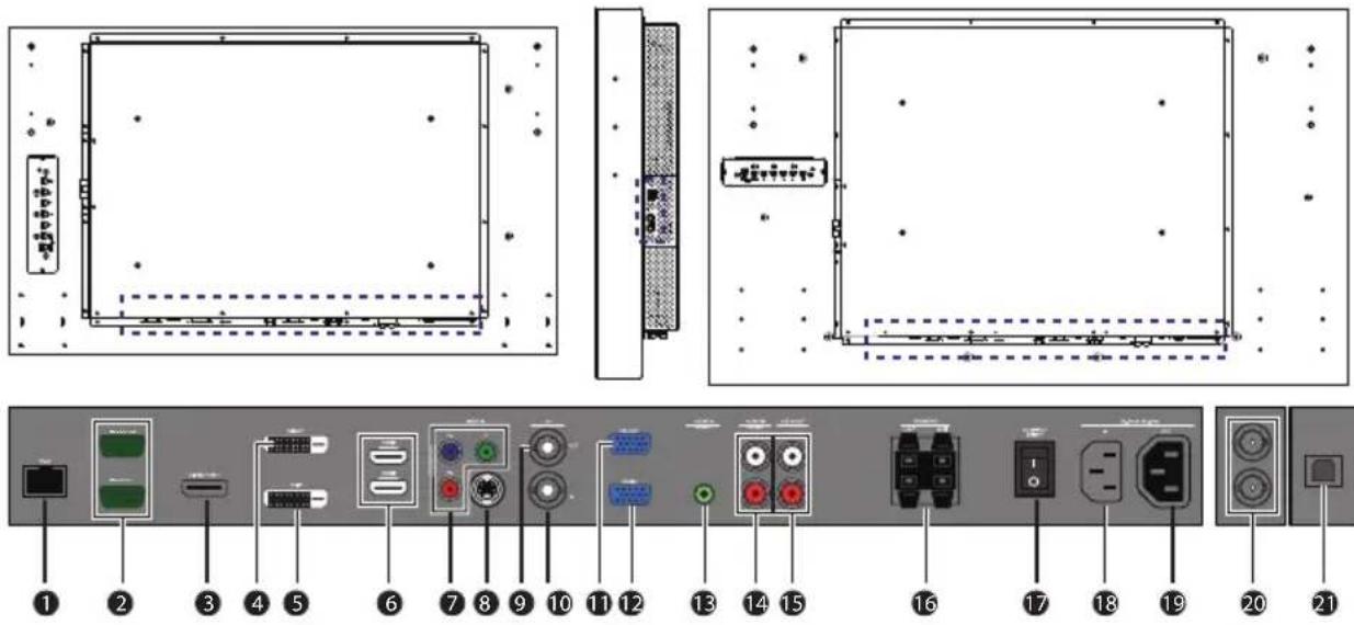
No
Name Description
1 RJ-45 Connects to the RJ-45 port on your Ethernet or router.
2 RS232C IN/OUT For external control and multi-display operation.
- RS232C IN: receives control signals from a computer or another display.
- RS232C OUT: outputs control signals from the RS232C IN input to another display.
3 DISPLAY PORT Connects to a DisplayPort compatible device.
4 DVI-OUT Outputs DVI signals from the DVI-IN to another display.
5 DVI-IN Receives DVI signals from an external device (such as a computer).
6 HDMI-1/HDMI-2 Receives HDMI signals from an external device (such as a Blu-ray disc player).
7 VIDEO IN (YPbPr) Receives component video (YPbPr) signals from an external device (such as a DVD player, HDTV device or Laser disc player).
8 VIDEO IN (S-VIDEO) Receives S-Video signals from an external device (such as a VCR or DVD player).
9 AV OUT Outputs composite video signals from the AV IN input to another display.
10 AV IN Receives composite video signals from an external device (such as a VCR or DVD player).
11 VGA OUT Outputs analog RGB signals from the VGA IN input to another display.
12 VGA IN Receives analog RGB signals from an external device (such as a computer).
| 13 | AUDIO IN (AUDIO1) | Receives audio signals from an external device (such as a computer). |
| 14 | AUDIO IN (AUDIO2) | Receives audio signals from an external device (such as a VCR or DVD player). |
| 15 | AUDIO OUT (R/L) | Outputs audio signals to an external device. |
| 16 | SPEAKERS (R/L) | Outputs audio signals to external speakers. |
| 17 | AC SWITCH ON/OFF | Turns on or off the main power. |
| 18 | AC IN Connects to a power outlet via the supplied power cord. | |
| 19 | AC OUT | Relays the AC power from the AC IN jack to another display. |
| 20 | SDI-in/SDI-out* | Connects SDI cables for SDI input/output signal. |
| 21 | USB FOR TOUCH | Connects the USB cable from the display to a computer to use the touch module. |
*Available in HD-SDI models.
Remote control
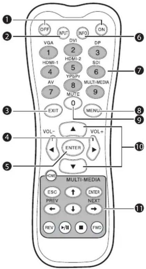
text_image
OFF INPUT INFO ON VGA 1 HDMI-1 2 HDMI-2 3 DP 4 5 6 SDI AV 7 8 MUTE 9 MULTI-MEDIA 0 EXIT MENU VOL- VOL+ ENTER HOME MULTI-MEDIA ESC PREV ↑ ENTER NEXT REV ▶/II ▪ FWD ① ② ③ ④ ⑤ ⑥ ⑦ ⑧ ⑨ ⑩1 ON/OFF
Turns the display on or off.
2 INPUT
Selects an input source.
3 EXIT
Returns to a previous menu or closes the OSD menu.
4 ◀ / VOL- / ▶ / VOL+
- Scrolls through settings and options in the OSD menu.
- Turns down/up the volume.
5 ENTER
Confirms your selection or save changes.
6 INFO
Shows the current input source and resolution.
7 Numeric buttons (1-9) /Input source buttons
- Performs as numeric buttons when the OSD menu is on.
- Performs as input source buttons when the OSD menu is off.

SDI and MULTI-MEDIA functions are not available with this display.
8 MENU
Opens or closes the OSD menu.
9 Numeric button (0)/MUTE
- Performs as a numeric button when the OSD menu is on.
- Turns on or off the mute function.
10 ▲/▼
Scrolls through settings and options in the OSD menu.
11 MULTI-MEDIA buttons
These functions are not available with the display.
Using the remote control
Installing remote control batteries
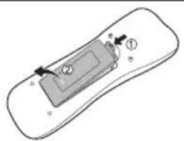
natural_image
Diagram of a device with labeled components (no text or symbols present)- Open the remote control battery compartment cover.

natural_image
Diagram of a remote control panel with battery and indicator lights (no text or symbols)- Insert the supplied batteries ensuring that the positive and negative marked battery terminals match the (+) and (-) marks in the battery compartment.
The supplied batteries are provided for your convenience so that you can operate the display straight away. You should replace them as soon as possible.
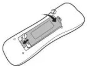
natural_image
Diagram of a device with a rectangular component and directional arrows indicating movement or force (no text or symbols)- Refit the battery compartment cover.
Remote control usage tips
- Point and aim the top front of the remote control directly at the display's remote control sensor window when you press the buttons.
- Do not let the remote control become wet or place it in humid environments (like bathrooms).
- If the display's remote control sensor window is exposed to direct sunlight or strong light, the remote control may not operate properly. In this situation, change the light source, readjust the angle of the display or operate the remote control from a location closer to display's remote control sensor window.
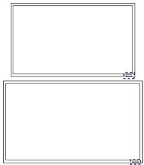
natural_image
Two empty rectangular frames with dashed lines at the bottom (no text or symbols)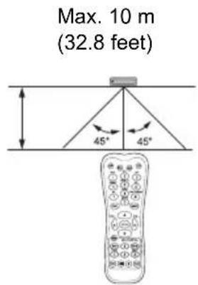
text_image
Max. 10 m (32.8 feet) 45° 45°Connection
Connecting audio/video signals
Pay attention to the following notes when you connect cables:
- Please turn off all devices.
- Familiarize yourself with the audio/video ports on the display and the devices you want to use. Be aware that incorrect connections may adversely affect picture quality.
- Do not remove cables from the ports by pulling the cable itself. Always grasp and pull the connectors at the end of the cable.
- Ensure that all cables are fully inserted and firmly seated.
Connecting the VGA input
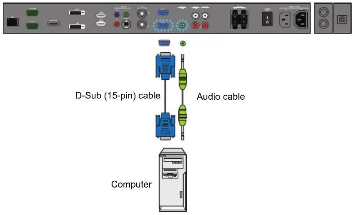
- Connect the VGA IN jack on the display to the VGA output jack on a computer using a D-Sub (15-pin) cable.
- Connect the computer's audio output jack to the AUDIO IN (AUDIO1) jack on the display using a suitable audio cable.
- To view images from this input, press the VGA button on the remote control.
text_image
D-Sub (15-pin) cable Audio cable Computer
The audio cable is not supplied and should be purchased separately.
Connecting the digital input
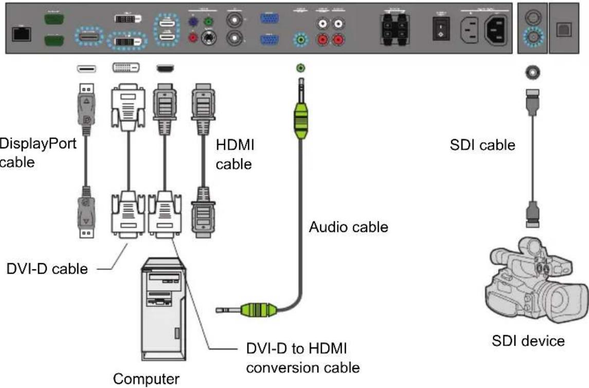
- Connect the DVI-IN/DISPLAY PORT/HDMI-1/HDMI-2/SDI jack on the display to the DVI-D/DisplayPort/HDMI output jack on a computer or equipment using a DVI-D/DisplayPort/HDMI/SDI or a DVI-D to HDMI conversion cable.
- If needed, connect the computer's audio output jack to the AUDIO IN (AUDIO1) jack on the display using a suitable audio cable.
- To view video image from this input, press the DVI or DP/HDMI-1/HDMI-2 button on the remote control.
text_image
DisplayPort cable DVI-D cable HDMI cable Audio cable DVI-D to HDMI conversion cable Computer SDI cable SDI device
The cables are not supplied and should be purchased separately.
Connecting the YPbPr component video input
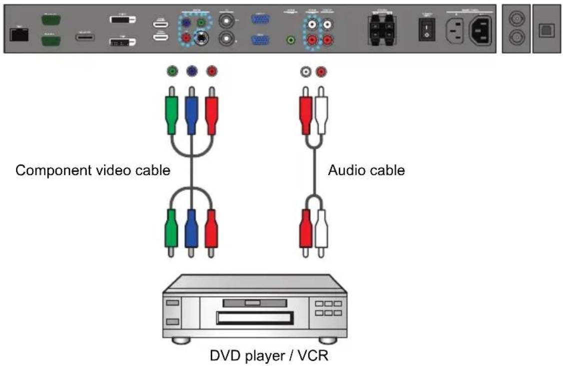
- Connect the VIDEO IN (YPbPr) jacks on the display to the component output jacks on an A/V device (such as a VCR or DVD player) using a component video cable.
- Connect the DVD player's audio output jacks to the AUDIO IN (AUDIO2) jacks on the display using a suitable audio cable.
- To view video image from this input, press the YPbPr button on the remote control.
text_image
Component video cable Audio cable DVD player / VCR
The cables are not supplied and should be purchased separately.
Connecting the AV and S-Video inputs
- Connect the VIDEO IN (S-VIDEO) or AV IN jack on the display to the output jack on an A/V device (such as a VCR) using an appropriate video cable.
- Connect the VCR's audio output jacks to the AUDIO IN jacks on the display using a suitable audio cable.
- To view video image from this input, press the AV button on the remote control for the AV signal, or press the INPUT button repeatedly for the S-Video signal.

text_image
AV cableS-V Audi cable DVD player / VCR
The cables are not supplied and should be purchased separately.
Connecting external speakers
The built-in amplifier on the display allows you to output audio signals through external speakers. Connect external speakers to the SPEAKERS (R/L) jacks on the display.
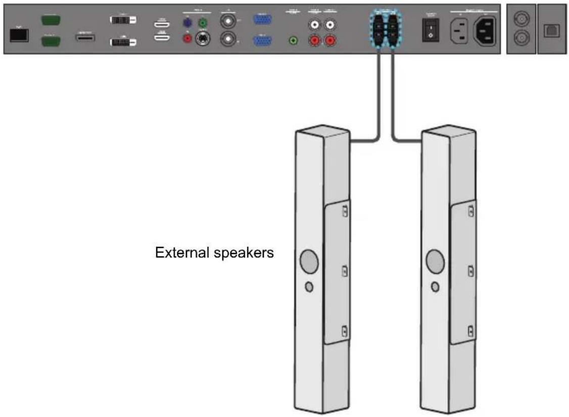
text_image
External speakers
You can use the remote control or the control panel on the display to adjust the volume.
Connecting multiple displays
You can connect multiple displays serially (daisy chain) to a computer for management. The number of displays you can connect serially depends on the resolution of the input signal you use.
Additional display
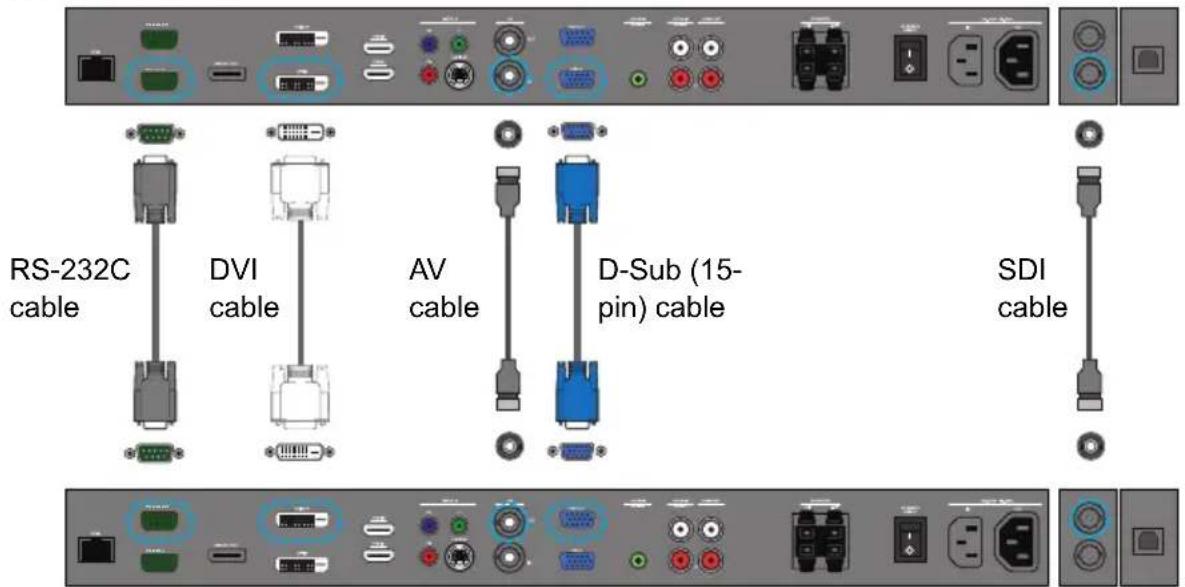
text_image
RS-232C cable DVI cable AV cable D-Sub (15- pin) cable SDI cableThe first display

- This RS-232C daisy chain application requires an RS-232C port equipped computer.
- Avoid using HDCP source for daisy chain application.
Connecting the touch module
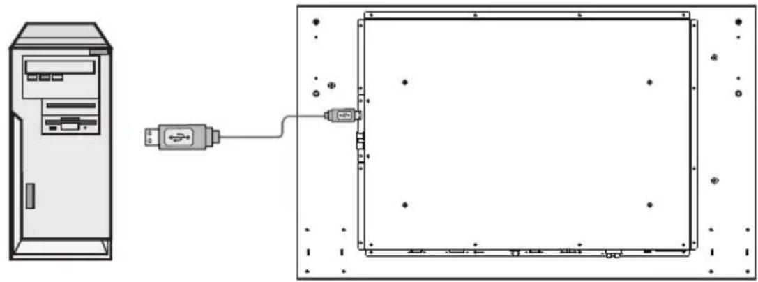
Connect the USB cable on the display to a computer.
The touch module supports easy Plug-and-Play operations. There is no need to install additional drivers on the computer.
natural_image
Diagram showing a desktop computer tower connected to an attached USB cable, with no visible text or symbols.Connecting power
-
Plug one end of the power cord into the AC IN jack on the display and the other end into an appropriate power outlet (if the outlet is switched, turn on the switch).
-
Press the power switch to turn on the main power.
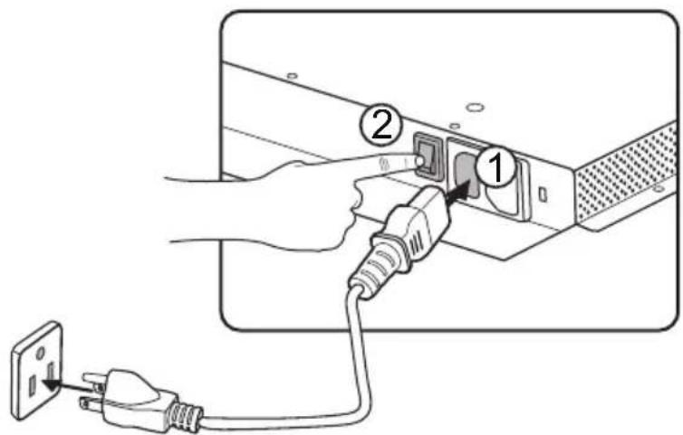
text_image
Diagram showing connection between a device with labeled parts, including plug and power plug connections
- The supplied power cord is suitable for use with 110-240V AC power only.
- The power cord and outlet illustrated may differ from the ones used in your region.
- Only use an appropriate power cord for your region. Never use a power cord which appears damaged or frayed, or change the plug type on the power cord.
- Be aware of the power loading when you use extension cords or multiple outlet power boards.
- There are no user serviceable parts in this display. Never unscrew or remove any covers. There are dangerous voltages inside the display. Turn off the power and unplug the power cord if you intend to move the display.
Using the Touch Screen (for Touch Model Only)
You can use the optical touch screen to control your operating system. The touch screen can emulate basic mouse functions and supports multi-touch functions for Windows 7*. The following table shows a list of gestures you can use on the touch screen.

- Ensure that you have installed the USB cable on the display to a computer.
- *Multi-touch functions are only supported by Windows 7 - Home Premium, Professional, Enterprise and Ultimate versions. For Windows XP, Windows Vista and Windows 7 - Starter and Home Basic versions, multi-touch is not supported.
- Windows is a registered trademark of Microsoft Corporation in the United States and other countries.
| OS functions Gesture actions | |
| For Windows XP, Windows Vista and Windows 7 | |
| Click Tap the screen once. | 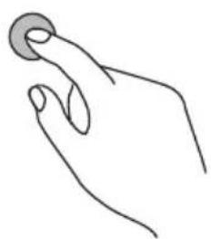 |
| Double-click Tap the screen twice. | 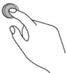 |
Right-click 1. Press on the target.2. Hold and wait for a blue ring to appear.3. Release your finger.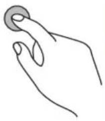 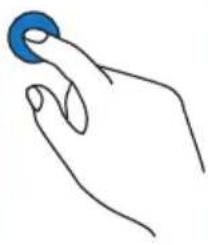 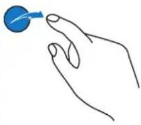 | |
Drag Drag one finger left or right. 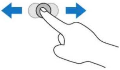 | |
| For Windows Vista and Windows 7 | |
Selection Drag one finger left or right. 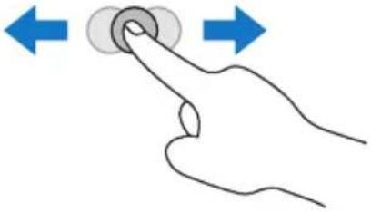 | |
| Pan up / Pan down / Back / Forward | Quickly drag your finger (Flick) in a desired direction. 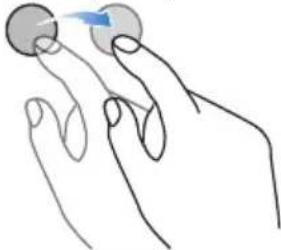 |
| Multi-touch functions For Windows 7 - Home Premium, Professional, Enterprise and Ultimate versions | |
Right-click 1. Press on the target.2. Tap the screen with another finger.3. Release the second finger. 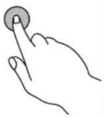 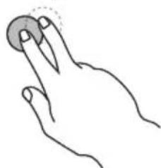 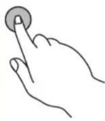 | |
Scrolling Drag one or two fingers up or down. 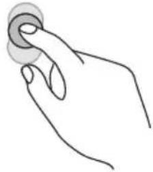  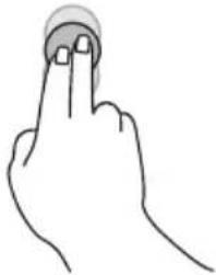 | |
Zoom Move two fingers apart or toward each other. 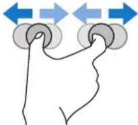 | |
| Supported by specific applications | ·Move two fingers in opposing directions. ·Use one finger to pivot around another. 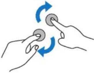 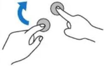 |
| Supported by specific applications | Tap two fingers simultaneously. The target should be the midpoint between the fingers. 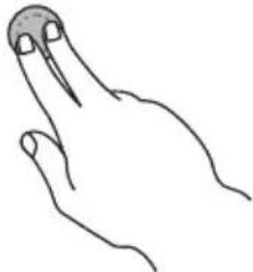 |
| For Windows XP, Windows Vista and Windows 7 | |
| Wakeup from Windows sleep mode (S3) | Press and hold for 4 seconds. 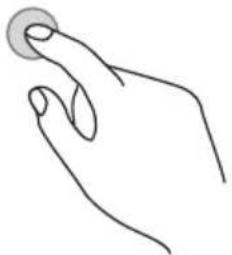 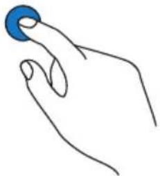 |
| Gesture Description | |
| For Windows 8 | |
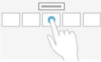 | Press and hold to learnThis touch interaction causes detailed information or teaching visuals (for example, a tooltip or context menu) to be displayed without a commitment to an action. Anything displayed this way should not prevent users from panning if they begin sliding their finger. |
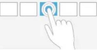 | Tap for primary actionTapping on an element invokes its primary action, for instance launching an application or executing a command. |
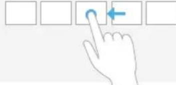 | Slide to panSlide is primarily used for panning interactions but can also be used for moving, drawing or writing. Slide can also be used to target small, densely packed elements by scrubbing (sliding the finger over related objects such as radio buttons). |
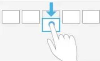 | Swipe to select, command, and moveSliding the finger a short distance, perpendicular to the panning direction, selects objects in a list or grid (ListView and GridLayout controls). Display the AppBar with relevant commands when objects are selected. |
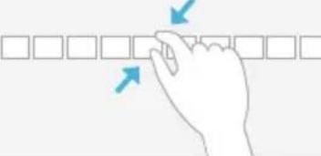 | Pinch and stretch to zoomWhile the pinch and stretch gestures are commonly used for resizing, they also enable jumping to the beginning, end, or anywhere within content with Semantic Zoom. A SemanticZoom control provides a zoomed out view for showing groups of items and quick ways to dive back into them. |
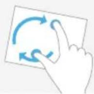 | Turn to rotateRotating with two or more fingers causes an object to rotate. |
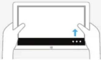 | Swipe from edge for app commandsApp commands are revealed by swiping from the bottom or top edge of the screen. Use the AppBar to display app commands. |
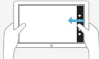 | Swipe from edge for system commandsSwiping from the right edge of the screen reveals the charms which contain system commands. Swiping from the left edge switches to previously used apps. Swiping from the top edge toward the bottom edge of the screen lets you dock or close apps. |
Calibrating the Touch Screen (for Touch Model Only)

- The function described in this section only applies to Windows operating systems.
- Ensure that you have installed the USB cable on the display to a computer.
You can calibrate the touch screen to use it more efficiently.
To adjust calibration:
- In Windows, tap the Start button and then Control Panel. In the search box, type Tablet PC Settings and tap Tablet PC Settings from the result list.
- On the Display tab, under Display Options, tap Calibrate. If you are prompted for an administrator password or confirmation, type the password or provide confirmation.
- Follow the instructions on the screen and tap Yes to save your calibration settings.
Important Instructions for Using the Touch Screen (for Touch Model Only)
- You can calibrate the touch screen using the Windows calibration routine.
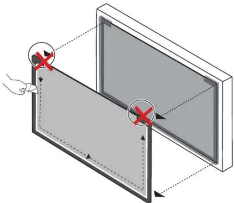
- Do not bend the retro-reflective bars. The touch screen cannot function normally if the bars are bent.
- Keep the touch screen out of direct sunlight or spotlights.
- Avoid displaying still images to prevent image retention.
- Regularly clean the retro-reflective bars with a clean, soft cloth. A dusty environment may adversely affect the performance of your touch screen. Clean the retro-reflective bars as illustrated below. Do not clean the touch sensors on the top of the screen.
natural_image
Diagram showing a hand interacting with a screen and panel, with red X marks indicating alignment or error zones (no text or symbols present)Basic operations
Turning the display on or off
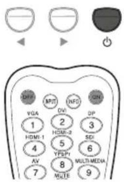
To turn on or off the display, press the power button on the display's control panel or on the remote control.
text_image
LAVA MPUT INFO LMIN VGA 1 HDMI-1 4 AV 7 DWI 2 HDMI-2 5 YFDP 8 MUTE OP 3 SDI 6 MULTI-MEDIA 9
- The display's standby mode still consumes power. To completely cut off power supply, disconnect the power cord from the power outlet.
- The display follows the VESA approved DPM Power Management function. The power management function is an energy saving feature that automatically reduces the display's power consumption when the keyboard or the mouse has not been used for a fixed period.
Locking/unlocking the controls
You can lock/unlock the control panel to prevent unwanted or accidental operations.
• Control panel buttons
To lock/unlock the control panel buttons, press and hold ◀ and ▶ simultaneously for 5 seconds. Once locked, the control panel buttons do not function unless unlocked.
- Remote control functions
To lock/unlock the remote control functions, press and hold MENU and ◀ for 5 seconds. Once locked, the display does not respond to any remote control operations unless unlocked.
Switching input signals
Press the INPUT button or those signal selection buttons on the remote control or the INPUT button on the control panel to select an input signal.
Adjusting audio volume level
Press ◀ / ▶ on the control panel or VOL+/VOL- on the remote control to adjust the volume.
Network connection
Connecting to a LAN
To set the display to connect to a local area network:
- Connect a RJ45 cable to the corresponding ports on the display and your LAN switch or router.
- Enter the OSD menu Setting > Control Setting. Select LAN.
-
Enter the next OSD menu Setting > Network Settings. If you are in a DHCP environment, select DHCP > Execute and press ENTER. Once done, the IP Address, Subnet mask, Default gateway, Primary DNS, and Secondary DNS settings will be displayed. If you are not in a DHCP environment, select Manual > Execute and press ENTER. Contact your ITS administrator for information on the IP Address, Subnet mask, Default gateway, Primary DNS, and Secondary DNS settings and enter it accordingly.
-
To save the settings and return to the previous menu, highlight Execute and press ENTER on the remote control.
Controlling the display
Once you have the correct IP address for your display and the display is on or in standby mode, you can use any computer that is on the same local area network to control the display.
- You cannot control the display via the RS-232C connector when LAN control is in use.
-
It is recommended that you use Internet Explorer versions 7.0 or higher browser.
-
Enter the IP address of the display in the address bar of your browser and press Enter.
-
The setting page appears.
-
Information: Shows information of the display. It is for information only. There are no items that can be set.
- Picture & Sound: Provides options for picture and sound adjustments.
- Screen: Provides options related to display adjustments.
- Setting: Provides options for advanced display adjustments.
- Mail Report: Provides options for setting up email accounts to receive status or error reports sent from the display.
- Network: Provides options for manually setting the display's IP address or obtaining an IP address from a DHCP server. Provides options for setting or changing the user name and password to secure this network control system.
Make sure the Setting > Control Setting menu is set to LAN if you would like to turn on the display from a web page.
The OSD (On-Screen Display) menu
OSD menu overview
| Menu name Options/functions | See page | |
| Picture | Picture ModeBacklightContrastBrightnessChromaPhaseSharpnessColor Temp. Noise ReductionFilm ModeReset | 38 |
| Sound | Sound ModeTrebleBassBalanceSurroundSpeakerAudio SourceReset | 39 |
| Screen | PAP SettingDisplay WallAspectAdjust ScreenFreezeTouch Feature | 40 |
| Setting | LanguageSchedulePower SaveControl SettingNetwork SettingsSet Monitor IDHDMI ControlAdvancedInformationAll Reset | 43 |

Some options are only available when a certain input signal source is selected.
Operations in the OSD menu
| Using the control panel buttons Using the remote control | |
1. Press MENU to open the OSD menu.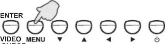 SOURCE SOURCE | 1. Press MENU to open the OSD menu.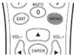 |
2. In the OSD menu, press ▲ or ▼ to select an item.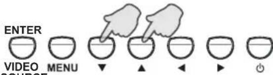 SOURCE SOURCE | 2. Press ▲ or ▼ to select an item.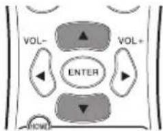 |
3. Press ENTER/VIDEO SOURCE to confirm selections.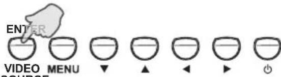 SOURCE SOURCE | 3. Press ENTER to confirm selections.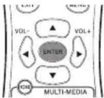 |
4. Press ▲ or ▼ to select a feature and press ◀ or ▶ to adjust settings. Press ENTER/VIDEO SOURCE to save changes.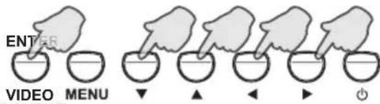 SOURCE SOURCE | 4. Press ▲ and ▼ to select a feature and press ◀ or ▶ to adjust settings. Press ENTER to confirm changes.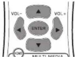 |
5. Press MENU to close the OSD menu.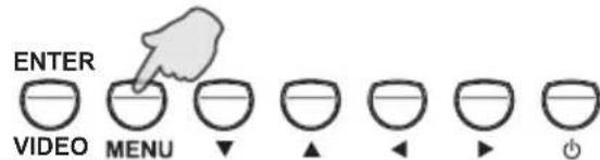 SOURCE SOURCE | 5. Press MENU to close the OSD menu.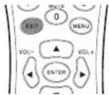 |
Picture menu
Picture
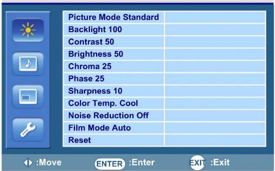
text_image
Picture Mode Standard Backlight 100 Contrast 50 Brightness 50 Chroma 25 Phase 25 Sharpness 10 Color Temp. Cool Noise Reduction Off Film Mode Auto Reset| Name Description | |
| Picture Mode Sets the display mode. | |
| Backlight Adjusts the backlight intensity for the screen. | This feature is not available if the Ambient Light Sensor or Adaptive Contrast function is set to On. |
| Contrast | Adjusts the image contrast. |
| Brightness | Adjusts the image brightness. |
| Chroma | Adjusts the color intensity of the image. |
| Phase | Adjusts the color tint of the image. |
| Sharpness | Adjusts the image sharpness. |
| Color Temp. | Adjusts the color temperature. |
| Noise Reduction | Reduces electrical image noise caused by different media players. |
| Film Mode | Optimizes the screen display automatically by detecting picture content and applying a reverse 3-2 or 2-2 pull-down process. The picture will be clearer and more natural. |
| This function is not available when displaying Picture and Picture (PAP).This function may not be correctly processed depending on the input signal. | |
| Reset | Resets all settings in the Picture menu. |
Sound menu
Sound
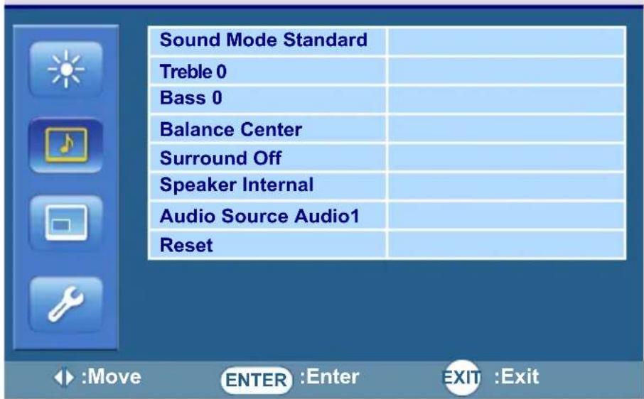
text_image
Sound Mode Standard Treble 0 Bass 0 Balance Center Surround Off Speaker Internal Audio Source Audio1 Reset| Name Description | |
| Sound Mode | Adjusts the sound output from the speakers. |
| Dynamic: Enhances treble and bass. | |
| Standard: Flat settings. | |
| Custom: Recalls the customized settings. | |
| Treble Adjusts the audio treble. | |
| Bass Adjusts the audio bass. | |
| Balance Adjusts the audio balance. | |
| Surround Turns the surround mode on or off. | |
| Speaker | Sets the audio source. |
| Line-Out: Selects the audio output source from AUDIO OUT (R/L) on the rear connector panel. | |
| External: Selects the audio output source from SPEAKERS (R/L) on the rear connector panel. | |
| Internal: Selects the audio output source from the internal speakers. | |
| Audio Source | Sets the audio input source. |
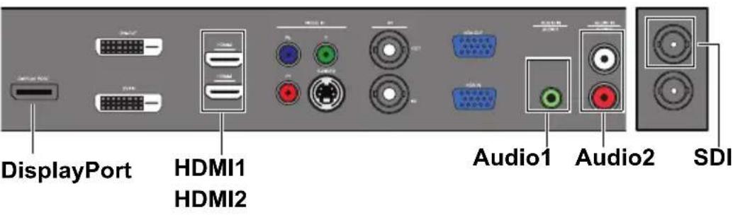 | |
| Reset | Resets all settings in the Sound menu. |
Screen menu
Screen
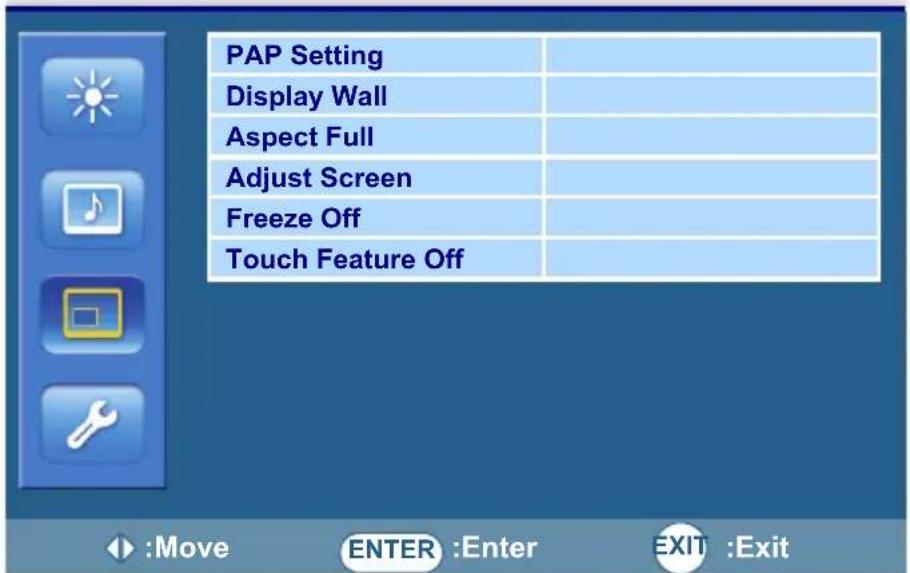
text_image
PAP Setting Display Wall Aspect Full Adjust Screen Freeze Off Touch Feature Off :Move ENTER :Enter EXIT :ExitName Description
| PAP Setting(Picture and Picture) | ·PAP: Turns on or off the PIP (Picture in Picture) and PBP (Picture by Picture) functions.·Active Picture: For the PIP, selects the main or sub picture to operate. For the PBP, selects the left or right picture to operate. Swaps the main/ sub or left/right pictures.·Picture Size: (PIP only) Changes the size of the sub picture.·Picture Position: (PIP only) Changes the position of the sub picture. |
| ·This feature is not available for Video and S-Video inputs.·PAP is not available for all signal source combinations. See "Supported PAP input signal combination" on page 52 for more information on supported combinations.·In PAP mode, only sound from the active picture will be available. | |
| Display Wall | ·H. Monitors/V. Monitors: Sets the number of displays used in the horizontal/vertical side.·H. Position/V. Position: Sets the horizontal/vertical position of the display wall matrix.·Frame Comp.: Adjusts images near the display edges for optimal demonstration across the display wall.·LED: Turns the power indicator on the display on or off.·Power On Delay: Choose to enable or disable a sequence in turning on the screen matrix. If enabled, the display will turn on one horizontal matrix starting from the top row. |
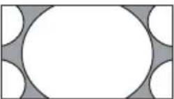
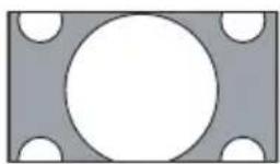
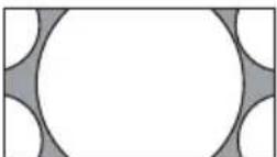
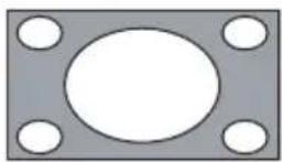
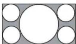
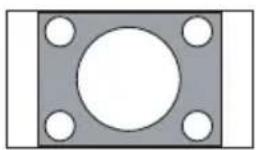
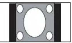
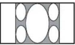
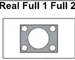
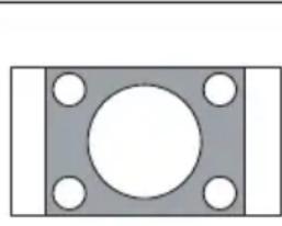
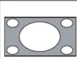
Aspect Sets the picture's aspect ratio.
- Wide Zoom: Enlarges to fill screen with minimum distortion.
- Zoom: Enlarges the picture, keeping the same aspect ratio.
• Full: Enlarges the picture horizontally to fill the screen when the picture source is 4:3 (Standard definition). When the picture source is 16:9 (High definition), it displays in the same 16:9 aspect ratio.
• 4:3: Displays all picture source in 4:3 aspect ratio.
• Full 1: Enlarges the picture to fill the screen in the vertical direction, keeping the same aspect ratio. A black frame may appear around the picture.
• Full 2: Enlarges the picture to fill the screen.
• Real: Displays the picture in its original number of dots.
| For video signal inputs | ||
| 4:3 original source | 16:9 Original source | |
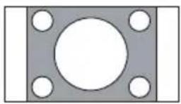 | 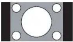 | 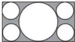 |
| Wide Zoom Wide Zoom | ||
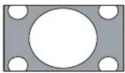 | 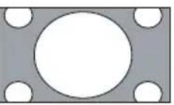 |  |
| Zoom Zoom | ||
 |  |  |
| Full Full | ||
 |  |  |
| 4:3 4:3 | ||
 |  |  |
| Aspect(continued) | For PC signal input | ||
 |  |  | |
| Adjust Screen | • Auto Adjustment: Sets whether to optimize image display for each VGA input.• Phase: Adjusts the phase of the VGA input image.• Clock Frequency: Adjusts the clock frequency of the VGA input image.• H. Position: Adjusts the horizontal position of the VGA input image.• V. Position: Adjusts the vertical position of the VGA input image. | ||
| Freeze Freezes the displayed image. | |||
| Touch Feature | When turned on, Aspect, PIP, Overscan and Display Wall will be disabled to optimize touch performance.This feature is only available for VGA, DVI and HDMI inputs. | ||
Setting menu
Setting
text_image
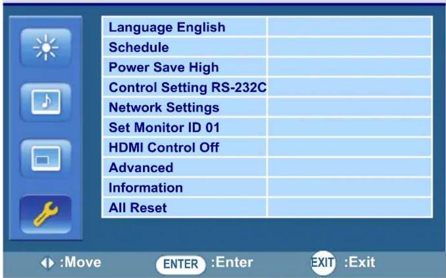
Language English Schedule Power Save High Control Setting RS-232C Network Settings Set Monitor ID 01 HDMI Control Off Advanced Information All ResetName Description
Language Sets your preferred language for the OSD menu.
Schedule
- Date and Time: Sets the current date and time.
- Clock Display: Sets whether to show the current time which was set.
- Input: Sets an input source to display when the display is automatically turned on next time.
- On/Off Timer: Sets when to turn on or off the display.

- Set the current time before you set the On/Off Timer.
- When schedule settings overlap, the Everyday setting takes priority over other weekly settings.
Power Save
Sets the display to enter the power saving mode when there is no signal detected.
- Low: All source can enter the power saving mode and wake up the display.
- High: All source can enter the power saving mode, but only a VGA signal can wake up the display or you have to press the power button to wake up the display when other source is connected.
- Off: If no source is detected, the backlight will continue on.

- Serial can bring any mode out of the power saving status.
• LAN can bring Low mode out of the power saving status.
| Control Setting | • RS-232C/LAN: Sets a terminal to control the display. • IR Passthrough: Select it when multiple displays are connected via RS-232C cables. - Primary: Designate the display as the primary unit for remote control operation. Only this display will be operated by the remote control. - Secondary: Designate the display as the secondary unit. The display can not be operated by the remote control, and will only receive the control signal from the primary display via the RS-232 connection. |
| Network Settings | See "Network connection" on page 34 for details. |
| Set Monitor ID | Assigns an ID number for the current display when multiple displays are connected.  For use when under the RS-232C control mode. For use when under the RS-232C control mode. |
| HDMI Control | Uses the HDMI CEC (Consumer Electronics Control) industry standard protocol to share functionality between connected devices and the display. To transfer system commands, you need to use an HDMI cable to connect the display to a device equipped with HDMI CEC. Select On in this menu and you can operate the main functionalities on your display and the connected device with one remote control. |
| Advanced | • Auto Search: Automatically detects available input sources.• Auto Adjustment: Automatically optimizes image display for the VGA input.• Overscan: Turns the overscan function on or off.• RGB Signal: Sets the type of signal for a piece of video equipment or PC connected to the HDMI of the display• Anti-Burn-In: Turns Anti-Burn-In function on or off. When turned on, you can select a mode to perform and a time interval to activate the function.- Mode A (ps: frame): Executes fast.- Mode B (ps: line): Slower but more precise than mode A.- Mode C (ps: dot): Slowest but the most precise mode.• OSD Rotation: Adjusts the OSD rotation. See product specifications for models recommended for portrait orientation. Landscape only models operated in portrait mode may result in premature failure and will not be covered under the warranty.• OSD Info Box: When turned On, switching signal inputs, or changing timing, the display will show the current input source and resolution onscreen. Select Off to show the information box onscreen only when you press INFO on the remote control.• Adaptive Contrast: Turns the Adaptive Contrast function on or off. This feature enhances image contrast for dark scenes.This feature is not available if the Ambient Light Sensor function is set to On.• Ambient Light Sensor: When turned On, the image brightness will adjust automatically as the ambient lighting conditions change. |
| Information | Displays the following information of your display.• Date• Model Name• Serial Number• Operating Time• Software Version• LAN Version• IP Address |
| All Reset | Returns all settings to factory default values. |
Product information
Specifications
| Item Specifications | ||
| TX-32 TX-42 | ||
| LCD panel | Active area (H x V mm) 698.4 x 392.85 927.94 x 521.96 | |
| Pixel pitch (mm) 0.3637 x 0.3637 0.4833 x 0.4833 | ||
| Native resolution (pixels) | 1920 x 1080 | |
| Brightness (cd/m2)(typical) | 350 400 | |
| Contrast (typical) 3000:1 1000:1 | ||
| Adaptive contrast 14300:1 32800:1 | ||
| Response time (ms)(typical) | 6.5 9 | |
| Touch | Technology | Optical 4S Touches |
| Resolution | 32767 x 32767 | |
| Capacity | Multi-touch up to 4 touchesMulti-touch gestures up to 5 touches | |
| Accuracy | +/- 3.0 mm 100% of touchable active area (up to 55")+/- 5.0 mm 100% of touchable active area (over 55") | |
| Touch Output | USB 2.0 | |
| PC | Supports Windows 8/7/Vista/XP, Mac OSX, and Linux | |
| Glass | Tempered glass | 5 mm + 0 mm/-0.3 mm |
| Input | Computer | VGA (D-Sub 15-pin) |
| Video | DVI (DVI-D), Composite Video (BNC jack), S-Video, YPbPr (RCA jacks), HDMI x 2, DisplayPort | |
| Audio | L/R (RCA jacks), Line-in (3.5 mm jack) | |
| Control | RS-232C (D-Sub 9-pin), RJ45 (Jack RJ45 W/LED I)USB (SKT USB2.0 A RT4P) | |
| Output | Computer | VGA (D-Sub 15-pin) |
| Video | DVI (DVI-D), Composite Video (BNC jack) | |
| Speaker | External speaker jack(10W+10W, 8 Ohms) External speaker jack(12W+12W, 8 Ohms) | |
| Audio | L/R (RCA jacks) | |
| Control | RS-232C (D-Sub 9-pin) | |
| Power | Supply | 100 - 240V AC, 50/60 Hz |
| Consumption Max. | < 85 W < 150 W | |
| Consumption Standby < 0.5 W | ||
| Environment | Operating Temperature | 0 - 40°C, 32 - 104°F | |
| Operating Humidity 10 - 90% (without condensation) | |||
| Storage Temperature | -20 - 60°C, 4 - 140°F | ||
| Storage Humidity 10 - 95% (without condensation) | |||
| Display Orientation Landscape/Portrait | |||
| Mechanical | Weight (lbs/kg) | 38.8/17.6 (Approximately) | 62.39/28.3 (Approximately) |
| Dimensions (W x H x D) (inch/mm) | 29.5 x 17.6 x 4/750 x 447 x 101.8 | 38.8 x 22.8 x 5.0/985 x 578 x 127.9 | |

Specifications and functions are subject to change without notice.
Dimensions
• TX-32
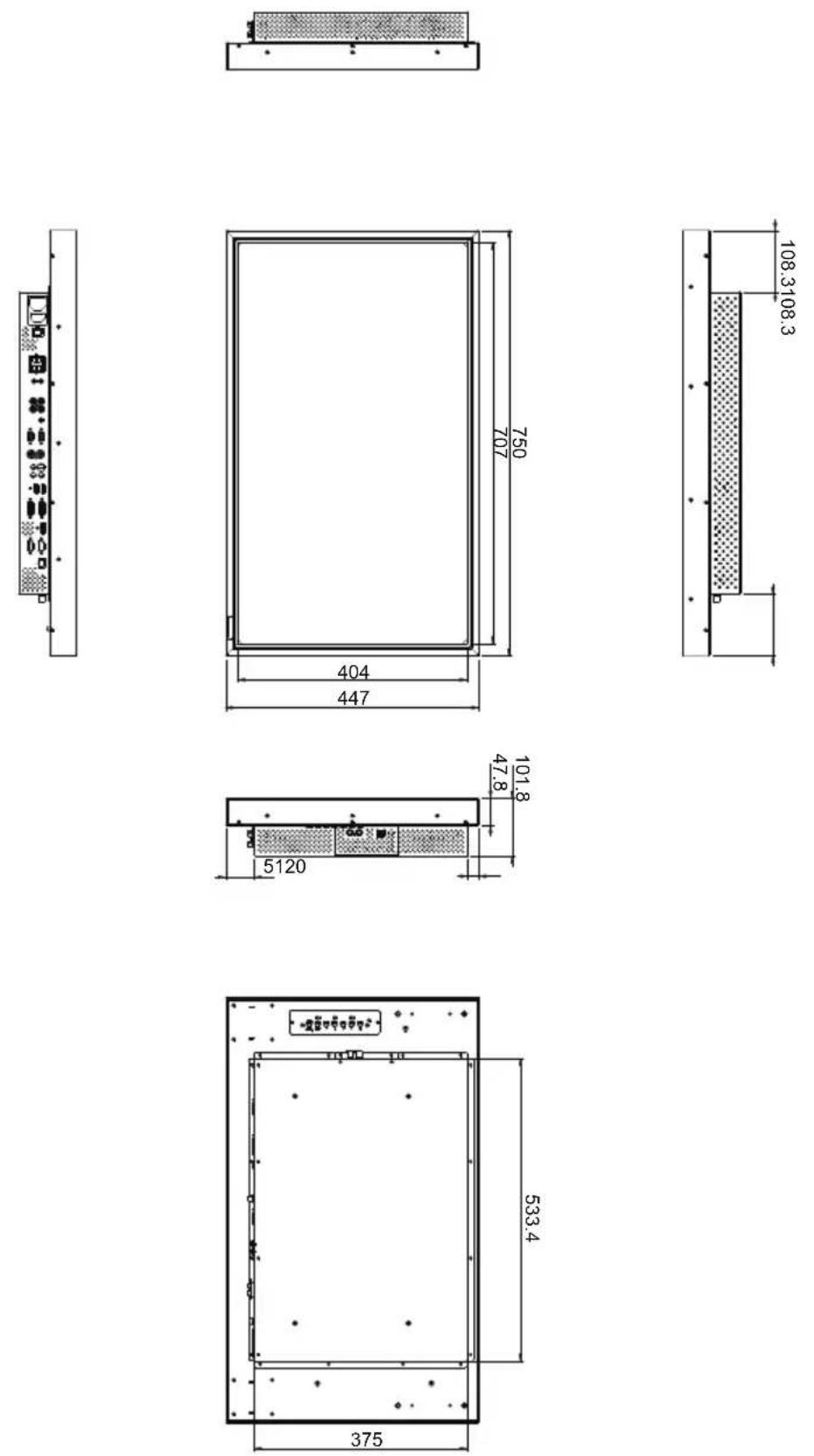
Unit: mm
• TX-42
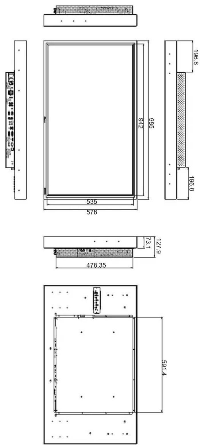
Unit: mm
Supported input signal resolution
Supported PAP input signal combination
| Problem Solution | |
| No picture Check the following:Is the display turned on? Check the power indicator of the display.Is the signal source device turned on? Turn on the device and try again.Are there any loose cable connections? Make sure that all cables are connected firmly.Have you chosen an unsupported output resolution on the computer? Refer to "Supported input signal resolution" on page 50 to select a supported resolution and try again.Have you chosen an unsupported output resolution on the DVD or Blu-ray disc player? Refer to "Supported input signal resolution" on page 50 to select a supported resolution and try again. | |
| No sound Check the following:Have you turned on the mute function on the display or the input source device? Turn off the mute function or increase the audio volume level and try again.Are there any loose cable connections? Make sure that all cables are connected firmly. | |
| The computer input image looks strange | Have you chosen an unsupported output resolution on the computer? Refer to "Supported input signal resolution" on page 50 to select a supported resolution and try again.Use the Auto Adjustment function (Refer to "Adjust Screen" on page 42) to let the display automatically optimize the display of computer image.If the result of the Auto Adjustment function is not satisfactory, use the Clock Frequency, Phase, H. Position and V. Position functions to manually adjust the image. |
| The control panel buttons do not work | Have you locked the control panel buttons? Unlock the buttons and try again. |
| The remote control does not work | Have you locked the remote control function? Unlock the function and try again.Check for incorrect battery orientation.Check for dead batteries.Check your distance and angle from the display.Check whether remote control is properly being pointed at the display's remote control sensor window.Check for any obstacle between the remote control and the remote control sensor window.Check that the remote control sensor window is not under strong fluorescent lighting, or in direct sunlight.Check for any devices (computer or personal digital assistant, PDA) nearby that transmit infrared signals which may cause interference to signal transmission between the remote control and the display. Turn off the infrared function of these devices. |