
Isys TPMC-9L - Monitor Crestron - Free user manual and instructions
Find the device manual for free Isys TPMC-9L Crestron in PDF.


| Product Type | Wall Mount Touch Screen Monitor |
| Brand | Crestron |
| Model | Isys TPMC-9L |
| Display Size | 9 inch (229 mm) diagonal |
| Display Resolution | 800 x 480 pixels (WVGA) |
| Display Type | TFT active matrix color LCD |
| Brightness | 350 nits |
| Contrast Ratio | 700:1 |
| Touch Screen Technology | Resistive membrane |
| Memory | 256 MB DDR SDRAM, 2 GB Flash |
| Dimensions (with faceplate) | 7.52 x 10.83 x 1.86 in (191 x 275 x 48 mm) |
| Weight | 2.6 lbs (1.2 kg) |
| Power Consumption | 23 Watts (0.96 Amps @ 24 VDC) |
| Power Source | Cresnet network power (24 VDC) |
| Processor | Core 3 UI, 16-bit color graphics engine |
| Communications | 10/100 Ethernet, Cresnet, USB 1.1 client |
| Video Input | Balanced and unbalanced composite video |
| Streaming Video | H.264 and MJPEG |
| Audio | Built-in microphone and speakers, Rava SIP Intercom, WAV playback |
| Push Buttons | 12 optional hard keys with custom engraving |
| Mounting Options | Wall, lectern, rack (optional kits) |
| Operating Temperature | 32° to 112° F (0° to 45° C) |
| Humidity | 10% to 90% RH (non-condensing) |
| Compliance | FCC Part 15 Class B, ICES-003, CE |
| Cleaning | Use a clean, damp, non-abrasive cloth with non-ammonia glass cleaner |
| Warranty | 3 years (limited) |
Frequently Asked Questions - Isys TPMC-9L Crestron
User questions about Isys TPMC-9L Crestron
0 question about this device. Answer the ones you know or ask your own.
Ask a new question about this device
Download the instructions for your Monitor in PDF format for free! Find your manual Isys TPMC-9L - Crestron and take your electronic device back in hand. On this page are published all the documents necessary for the use of your device. Isys TPMC-9L by Crestron.
USER MANUAL Isys TPMC-9L Crestron
Regulatory Compliance
As of the date of manufacture, the TPMC-9L has been tested and found to comply with specifications for CE marking and standards per EMC and Radiocommunications Compliance Labelling.

Federal Communications Commission (FCC) Compliance Statement
This device complies with part 15 of the FCC Rules. Operation is subject to the following conditions: (1) This device may not cause harmful interference and (2) this device must accept any interference received, including interference that may cause undesired operation.
CAUTION: Changes or modifications not expressly approved by the manufacturer responsible for compliance could void the user's authority to operate the equipment.
NOTE: This equipment has been tested and found to comply with the limits for a Class B digital device, pursuant to part 15 of the FCC Rules. These limits are designed to provide reasonable protection against harmful interference in a residential installation. This equipment generates, uses and can radiate radio frequency energy and, if not installed and used in accordance with the instructions, may cause harmful interference to radio communications. However, there is no guarantee that interference will not occur in a particular installation. If this equipment does cause harmful interference to radio or television reception, which can be determined by turning the equipment off and on, the user is encouraged to try to correct the interference by one or more of the following measures:
• Reorient or relocate the receiving antenna
- Increase the separation between the equipment and receiver
- Connect the equipment into an outlet on a circuit different from that to which the receiver is connected
- Consult the dealer or an experienced radio/TV technician for help
Industry Canada (IC) Compliance Statement
This Class B digital apparatus complies with Canadian ICES-003.
Features and Functions....1
Applications....4
Specifications 5
Physical Description....8
Setup....12
Network Wiring....12
Identity Code....12
Configuring the Touch Screen....13
Mounting Options....27
Touch Screen Mounting 27
Touch Screen Removal....31
Hardware Hookup 31
Recommended Cleaning....32
Programming Software....33
Software Requirements for the PC 33
Programming with Crestron SystemBuilder....33
Programming with SIMPL Windows....33
Programming with VisionTools 36
Push Button Programming ....40
Uploading and Upgrading....41
Establishing Communication....41
Programs, Projects and Firmware....43
Program Checks 43
Problem Solving 44
Troubleshooting....44
Check Network Wiring....45
Reference Documents....46
Further Inquiries....46
Future Updates 46
Return and Warranty Policies 47
Merchandise Returns / Repair Service 47
Crestron Limited Warranty....47
Isys® 9" Wall Mount Touch Screen: TPMC-9L
Introduction
The Isys ^® TPMC-9L Wall Mount Touch Screen from Crestron ^® delivers high end style and performance in a compact, cost effective flush mount design. Featuring a generous 9" (\~229 mm) widescreen display, advanced Core 3 UI ^™ touch screen graphics, high performance H.264 video and Rava ^™ SIP Intercom, the TPMC-9L delivers a world of control capability, yet leaves a very small footprint. The addition of 12 optional push buttons provides quick access to commonly used functions.
Features and Functions
- Stylish flush mount design for in-wall and lectern installation
- Generous 9" (\~229 mm) widescreen color touch screen
• 16-bit color graphics powered by Core 3 ^TM - 800 x 480 WVGA display resolution
• Automatic brightness control - Native H.264 streaming video for viewing Web cameras and HD sources
- Wired composite video input
• Rava SIP Intercom and phone technology
• WAV file customizable audio feedback - Crestron Home ^ CAT5 video connectivity
• High speed Ethernet and Cresnet ^® communications
• Built-in USB port for direct program upload - Includes faceplate with 12 "hard key" push buttons
- Custom button engraving available as solid or backlit text
- No-button blank faceplate also provided
• Wall, lectern and rack mounting options
• Available with almond, black or white textured finish
Advanced Touch Screen Control
A Crestron touch screen offers an ideal user interface for controlling all the technology in a home, boardroom, classroom, courtroom or command center. Touch screens do away with piles of remote controls, cluttered wall switches and cryptic computer screens, simplifying and enhancing the technology. For controlling home theater, multimedia presentation, audio, video, lighting, HVAC and other systems, Crestron touch screens are fully customizable with easy to use controls and icons, true feedback and real time status display, full-motion video windows and advanced navigation of digital media servers, tuners and other devices.
Powered by Core 3
Crestron touch screens have always offered the ultimate user experience. With Core 3 UI, they also deliver the ultimate value, enabling the creation of dynamically rich user interfaces with incredible efficiency and unparalleled functionality. User Core 3 UI, programmers can swiftly integrate fluid gesture-driven controls, animated feedback, metadata, embedded apps and full-motion video for a deeply engaging and ultra-intuitive touch screen experience.
Some Core 3 UI enhancements:
- Cool looking graphical buttons, sliders, knobs and gauges are intuitive and fun to use.
- Kinetic effects enhance the feeling of realism with lists and toolbars that scroll with momentum at the flick of a fingertip.
- Drag and drop objects snap into place offering an easy way to assign assets to rooms.
- Desktop widgets personalize the touch screen with animated clocks, calendars, weather, news and other information.
- Customizable themes allow a completely different look and feel for every user, event or season.
- Fully developed SmartObjects™ enable sophisticated control over complex devices with minimal programming.
- Smart resizing scales objects perfectly and instantly for faster GUI development, even across different sized touch screens.
Integrated Video
High performance streaming video capability makes it possible to view security cameras and other video sources over the network right on the touch screen. Native support for H.264 and MJPEG formats allows the TPMC-9L to display live video images from Web cameras and servers such as the Crestron CEN-NVS200 Network Video Streamer (sold separately). A wired video input is also provided to allow viewing of a composite video source. Video images can be displayed full frame or in fully scalable windows anywhere on the touch screen.
Rava SIP Intercom
Rava SIP Intercom technology enables hands free VoIP communication between any two Rava-enabled Crestron touch screens. Rava works over Ethernet, supporting 2-way intercom, video intercom*, paging and room monitoring without any special wiring. VoIP phone capability is also possible through integration with a SIP-compatible IP phone system or SIP server, allowing hands free telephone functionality complete with speed dialing, caller ID, custom ringers and other enhancements. Built-in echo cancellation affords true duplex performance for clear, seamless voice communication using the TPMC-9L's integrated microphone and speakers.
Audio Feedback
Customized WAV files can be loaded on the TPMC-9L to add another dimension to the touch screen graphics using personalized sounds, button feedback and voice prompts.
Push Button Options
The TPMC-9L features a faceplate containing 12 programmable “hard key” push buttons, elegantly trimmed by illuminated button dividers. Integral to the faceplate, the push buttons are positioned along the left and right edges of the touch screen, making it possible to align them with text and graphics onscreen. Custom engraving of the buttons is available, with a choice of solid or backlit text. A plain, no-button faceplate is also included, allowing a very clean appearance with no push buttons.
Auto-Brightness Control
The TPMC-9L maintains optimal visibility under varying lighting conditions, adjusting its button backlighting and display brightness smoothly and automatically according to changes in the ambient light level in the room.
High Speed Connectivity
Both Cresnet ^® and high speed Ethernet are standard on the TPMC-9L, providing for easy network integration and seamless communications with Crestron control systems and other network devices.
Versatile Flush Mount Design
The TPMC-9L is designed for easy flush mount installation in a wall, lectern or similar flat surface. Mounting clips furnished with the TPMC-9L facilitate a clean installation in drywall and many furniture applications. Additional mounting options are available separately.
Applications
The following diagram shows a TPMC-9L in a typical application.
TPMC-9L in a Typical Application
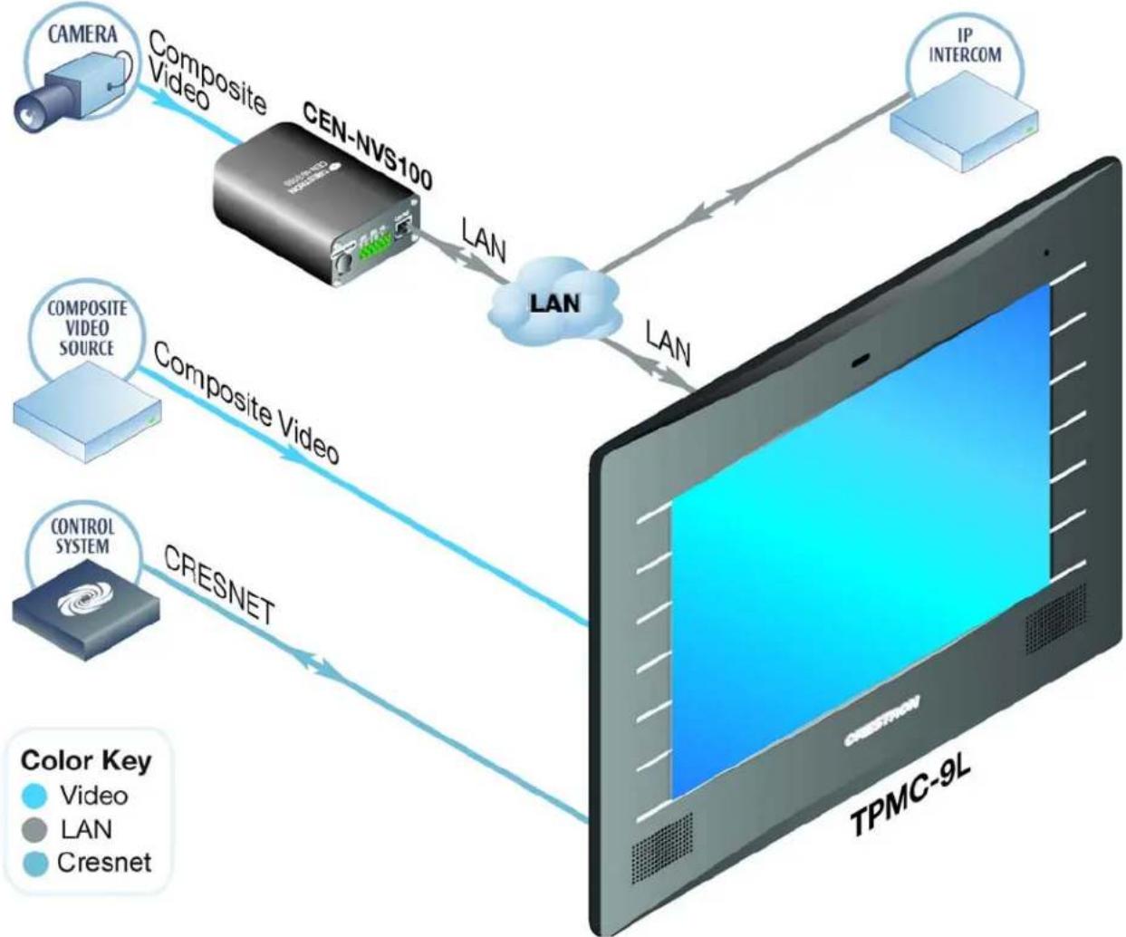
flowchart
graph TD
    A["CAMERA"] -->|Composite Video| B["CEN-NVS100"]
    B -->|LAN| C["LAN"]
    C -->|LAN| D["IP INTERCOM"]
    E["CONTROL SYSTEM"] -->|CRESNET| D
    F["COMPOSITE VIDEO SOURCE"] -->|Composite Video| C
    G["Color Key: Video, LAN, Cresnet"] --> H["TPMC-9L"]
Specifications
Specifications for the TPMC-9L are listed in the following table.
TPMC-9L Specifications
| SPECIFICATION | DETAILS |
| Touch Screen DisplayDisplay Type TFT active matrix color LCDSize 9 inch (229 mm) diagonalAspect Ratio 15:9 WVGAResolution 800 x 480 pixelsBrightness 350 nitsContrast 700:1Color Depth 24-bit, 16.7 M colorsIlluminationViewing Angle ± 88° horizontal, ± 88° verticalTouch Screen Resistive membrane | Edge lit fluorescent with auto-brightness control |
| MemoryDDR SDRAM 256 MBFlash 2 GBMaximum Project Size 40 MB | |
| Graphic Engine | Core 3 UI, 16-bit color depth (non-palette), VT Pro-e® programmable, supports pre-Core 3 projects |
| CommunicationsEthernet | 10/100, auto-switching, auto-negotiating, auto-discovery, full/half duplex, DHCP, for control and console |
| CresnetUSB | Cresnet slave mode for control and consoleUSB 1.1 client for console |
| VideoAnalog Input Signal TypesAnalog FormatsAnalog Color DepthStreaming Formats | CompositeNTSC 480i, PAL 576i24-bit, 16.7 M colorsH.264 (MPEG-4 part 10 AVC, MJPEG |
| AudioFeatures | Built-in microphone and speakers, Rava SIP Intercom, Crestron IP Intercom |
| Audio Feedback | WAV format, 8 & 16-bit PCM, 8 - 44.1 kHz sampling rates, mono & stereo |
| Power RequirementsCresnet Power Usage | 23 Watts (0.96 Amps @ 24 Volts DC) |
| Default IP ID1 | 03 |
| Minimum 2-Series Control System Update File2,3 | Version 3.155.1240 or later |
| Environmental | |
| Temperature 32° to 112° F (0° to 45° C) | |
| Humidity 10% to 90% RH (non-condensing) | |
| Heat Dissipation 78 BTU/Hr | |
| Enclosure | |
| Construction | Plastic, flush mountable using (4) clips provided (additional mounting kits sold separately) |
| Faceplate | Plastic, button and no-button faceplates included (optional solid or backlit button engraving sold separately) |
| Dimensions | |
| Height 7.52 in (191 mm) | |
| Width 10.83 in (275 mm) | |
| Depth 1.86 in (48 mm) | |
| Weight 2.6 lbs (1.2 kg) | |
| Available Models | |
| TPMC-9LA-T | Isys 9" Wall Mount Touch Screen, Almond Textured |
| TPMC-9LB-T | Isys 9" Wall Mount Touch Screen, Black Textured |
| TPMC-9LW-T | Isys 9" Wall Mount Touch Screen, White Textured |
| Included Accessories | |
| TPMC-9L-FP[A,B,W]-T_BLANK | Button Faceplate without Engraving, (specify color) |
| TPMC-9L-FP[A,B,W]-T-NB | No-button Faceplate, (specify color) |
| Available Accessories | |
| BB-9L | Pre-Construction Wall Mount Back Box |
| BBI-9L | Back Box – International Version |
| CEN-NVS200 | Network Video Streamer |
| CRESCAT | Crestron Home® CAT5 AV Cable |
| CRESNET | Cresnet Control Cable |
| MMK-9L | Mud Ring |
| PMK-9L | Pre-Construction Wall Mount Kit |
| RMK-9L | Rack Mount Kit |
| TMK-9L | Trim Ring |
| TPMC-9L-FP[A,B,W]-T_ENGRAVED | Button Faceplate with Custom Engraving (specify color) |
| TPMC-9L-FP-BKLT-[A,B,W]-T_ENGRAVED | Backlit Button Faceplate with Custom Engraving (specify color) |
| VMK-WIN | Touchpoint® Virtual Mouse & Keyboard Software for Windows® |
| WMKB-6L | Replacement Wall Mount Clips |
| Available Accessories(Continued) | |
| WMKM-9L | Post-Construction Wall Mount Kitwith Mud Ring |
| WMKT-9L | Lectern or Post-Construction Wall Mount Kitwith Trim Ring |
-
Refer to "Identity Code" on page 12 for details.
-
The latest software versions can be obtained from the Crestron Web site. Refer to the NOTE following these footnotes.
-
Crestron 2-Series control systems include the AV2 and PRO2. Consult the latest Crestron Product Catalog for a complete list of 2-Series control systems.
NOTE: Crestron software and any files on the Web site are for authorized Crestron dealers and Crestron Authorized Independent Programmers (CAIPs) only. New users must register to obtain access to certain areas of the site (including the FTP site).
Physical Description
This section provides information on the connections, controls and indicators available on the TPMC-9L.
TPMC-9L Physical View
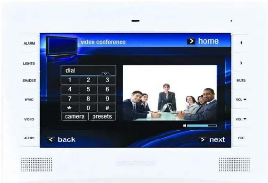
TPMC-9L Physical View (With No-Button Faceplate)
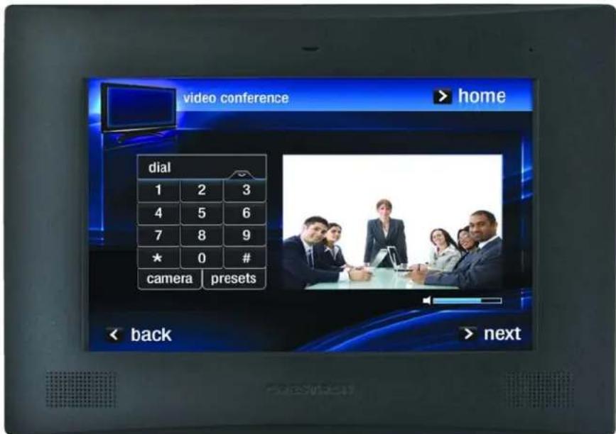
TPMC-9L Overall Dimensions (Front and Side Views, with Faceplate)
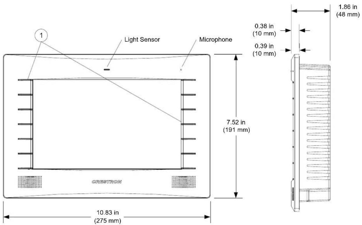
TPMC-9L Overall Dimensions (Front and Side Views)
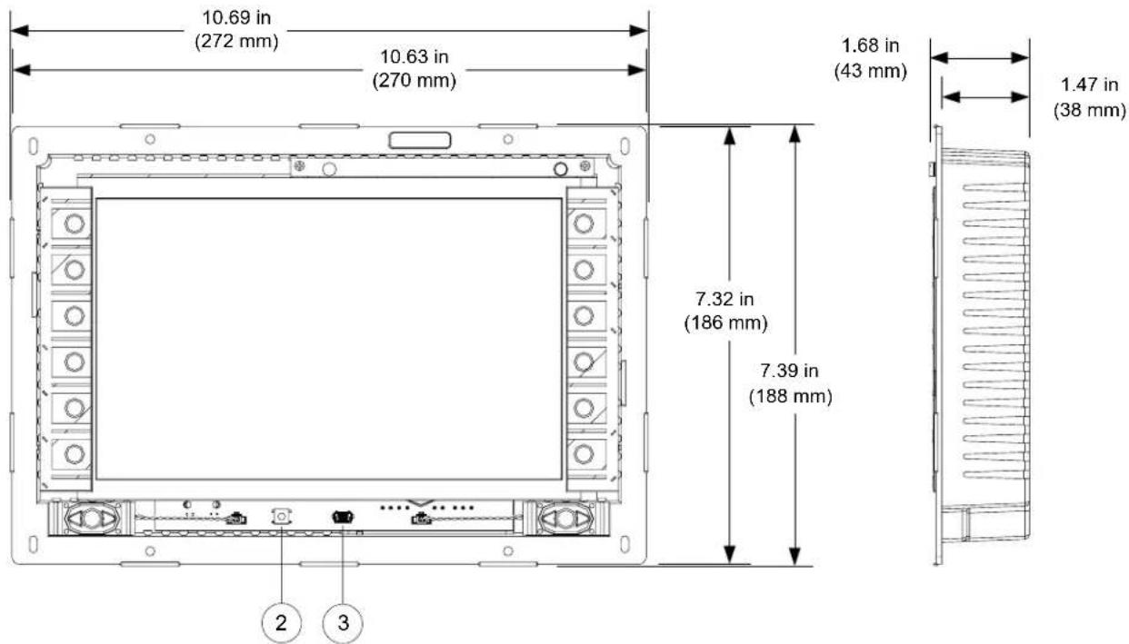
TPMC-9L Overall Dimensions (Rear View)
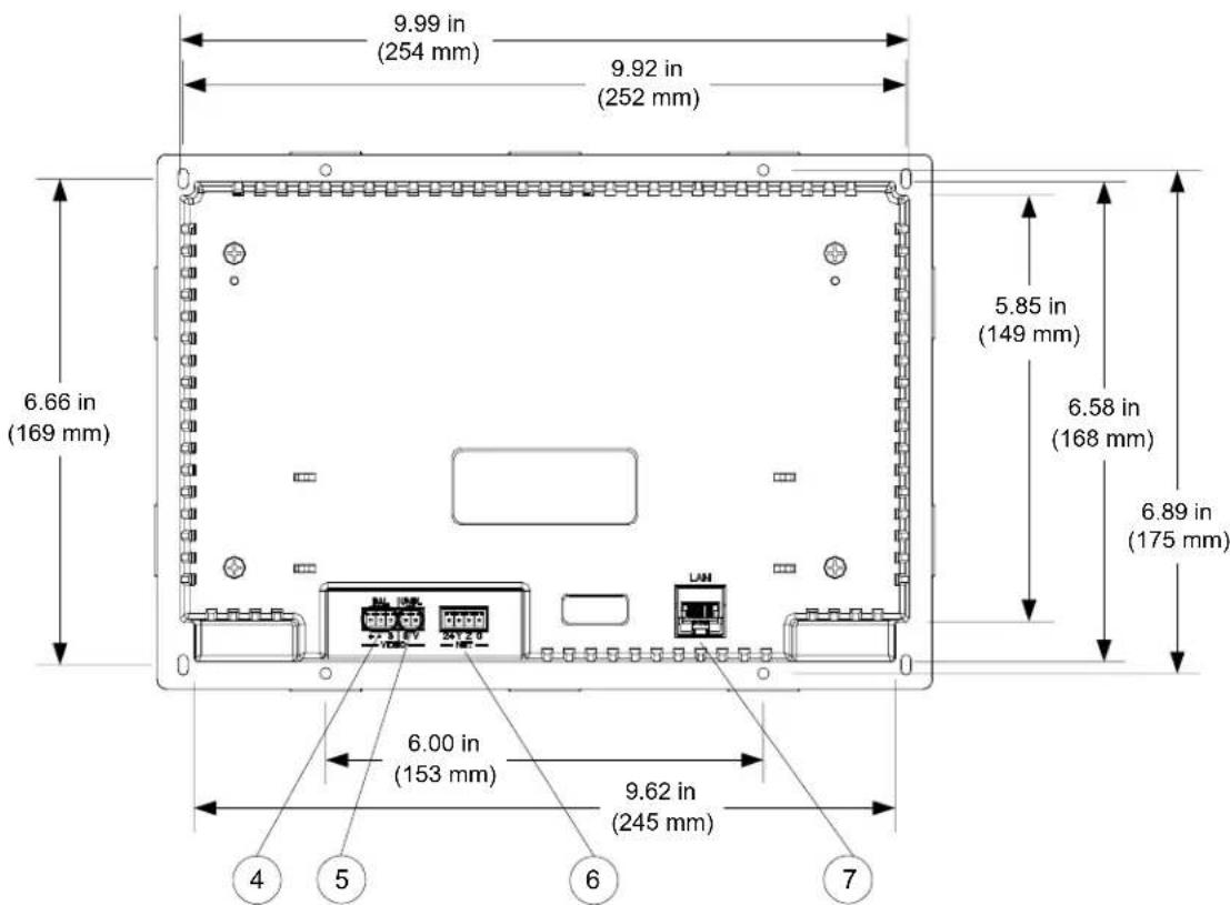
Connectors, Controls & Indicators
| # | CONNECTORS, CONTROLS & INDICATORS1 | DESCRIPTION | |||
| 1 | Hard Keys(12) Optional engravable push buttons, optional auto-dimmable backlighting | ||||
| 2 Reset Button | (1) Miniature push button for hardware reset (behind faceplate) | ||||
| 3 |  | (1) Mini-B USB 1.1 console port (behind faceplate); Mini-B to A USB cable included | |||
| 4 | VIDEO (BAL) ^2 BAL  | (1) 3-pin 3.5 mm detachable terminal block; Balanced composite video input; Input impedance: 100 Ω nominal; Input level: 1 V_p-p nominal, 1.5 V_p-p maximum; Maximum DC offset: ± 2 Volts; Connects to any Crestron CAT5 Video Out port via CresCAT ^ or CAT5 cable | |||
| 5 | VIDEO (UNBL) ^2 UNBL  | (1) 2-pin 3.5 mm detachable terminal block; Unbalanced composite video input; Input impedance: 75 Ω nominal; Input level: 1 V_p-p nominal, 1.5 V_p-p maximum; Maximum DC offset: ± 2 Volts; Connects to any conventional coax video source | |||
| 6 | NET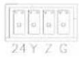 | (1) 4-pin 3.5 mm detachable terminal block; Cresnet slave port, connects to Cresnet control network24: Power (24 Volts DC)Y: DataZ: DataG: Ground | |||
| 7 | 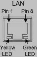 | (1) 8-wire RJ-45 with two LED indicators; 10/100BASE-T Ethernet port; Green LED indicates link status; Yellow LED indicates Ethernet activity | |||
| PIN SIGNAL PIN | SIGNAL | ||||
| 1 TX + 5 N/C | |||||
| 2 TX - 6 RX - | |||||
| 3 RX + 7 N/C | |||||
| 4 N/C 8 N/C | |||||
(Continued on following page)
1. Interface connectors for VIDEO and NET ports are provided with the unit.
2. Balanced and unbalanced video inputs are mutually exclusive.
Setup
Network Wiring
When wiring the Cresnet network, consider the following:
- Use Crestron Certified Wire.
- Use Crestron power supplies for Crestron equipment.
- Provide sufficient power to the system.
CAUTION: Insufficient power can lead to unpredictable results or damage to the equipment. Use the Crestron Power Calculator to help calculate how much power is needed for the system (www.crestron.com/calculators).
For networks with 20 or more devices, use a Cresnet Hub/Repeater (CNXHUB) to maintain signal quality.
For more details, refer to "Check Network Wiring" on page 45.
The TPMC-9L can also use high-speed Ethernet for communications between the device and a control system, computer, media server and other IP-based devices.
For information on connecting Ethernet devices in a Crestron system, refer to the latest version of the Crestron e-Control® Reference Guide (Doc. 6052), which is available from the Crestron Web site (www.crestron.com/manuals).
Identity Code
Net ID
The Net ID of the TPMC-9L has been factory set to 03. The Net IDs of multiple TPMC-9L devices in the same system must be unique. The Net ID is set using the internal setup menu (refer to “Cresnet” on page 20). Net ID may also be set from a personal computer (PC) via Crestron Toolbox™ (refer to “Establishing Communication” which starts on page 41).
When setting the Net ID, consider the following:
- The Net ID of each unit must match an ID code specified in the SIMPL Windows program.
• Each network device must have a unique Net ID.
For more details, refer to the Crestron Toolbox help file.
IP ID
The IP ID is set within the TPMC-9L's IP table using the internal setup menu (refer to "IP Table" which starts on page 16). IP ID may also be set from a PC via Crestron Toolbox. For information on setting an IP table, refer to the Crestron Toolbox help file. The IP IDs of multiple TPMC-9L devices in the same system must be unique.
When setting the IP ID, consider the following:
- The IP ID of each unit must match an IP ID specified in the SIMPL Windows program.
- Each device using IP to communicate with a control system must have a unique IP ID.
Configuring the Touch Screen
The TPMC-9L is configured from the setup menu.
NOTE: The only connection required to configure the touch screen is power. Refer to "Hardware Hookup" which starts on page 31 for details.
NOTE: The TPMC-9L can take up to 45 seconds to boot to a display after initial power up.
NOTE: If no project has been loaded or if an invalid project has been loaded, the touch screen displays an error message and defaults to the setup menu screen.
The setup screens allow basic configuration procedures prior to regular operation of the touch screen. To enter the setup screens, touch the panel while applying power to the unit. The setup screens can also be entered by touching the upper left corner, lower left corner, upper right corner and lower right corner of the panel twice in sequence (i.e., upper left, lower left, upper right, lower right, upper left, lower left, upper right, lower right). This sequence must be performed within five seconds and touches must be all the way in the corners.
An third way to enter the setup screens, for TPMC-9L touch screens using the button bezel, is to press the first four buttons from the top on the left side of the screen, twice in sequence (i.e., 1, 2, 3, 4, 1, 2, 3, 4). (Refer to "Push Button Programming" on page 40 for a diagram showing push button numbering.)
The main “Setup” menu opens, as shown in the illustration that follows. The functions provided by each button are detailed in subsequent paragraphs.
TPMC-9L "Setup" Menu
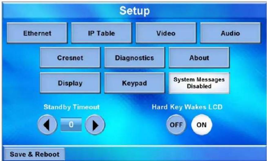
The “Setup” menu provides access to all basic functions and parameters. There are buttons for Ethernet, IP Table, Video, Audio, Cresnet, Diagnostics, About, Display and Keypad. There are also buttons to increase and decrease Standby Timeout, buttons to turn the Hard Key Wakes LCD function on or off, as well as a button to enable/disable system messages. A Save & Reboot button is provided to save settings and reboot the touch screen.
Ethernet
Touch Ethernet to enter the "Ethernet Setup Menu", shown in the illustration below.
"Ethernet Setup Menu"
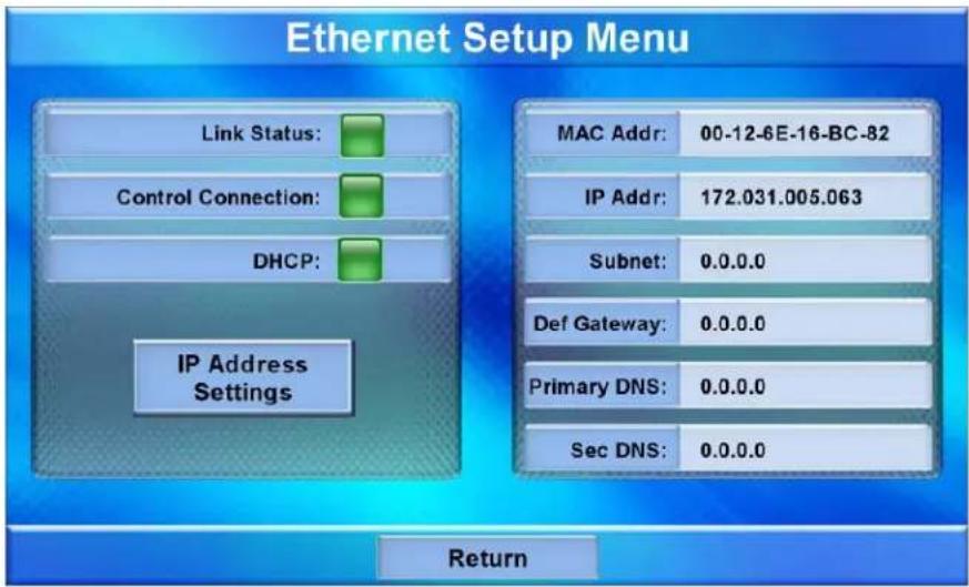
The “Ethernet Setup Menu” displays information about the Link Status, Control Connection, DHCP, MAC address, IP address, subnet, default gateway, primary DNS and secondary DNS. It also has an IP Address Settings button used to access the submenus for setting up IP address and DNS servers.
Touch IP Address Settings to enter the "IP Address" screen, shown in the illustration below. Touch Return to go back to the main "Setup" menu.
"IP Address" Screen
![IP Address Edit DNS Servers >> DHCP: Enabled [ Touch Setting to Edit ] Static IP Address: 000.000.000.000 [ Touch Setting to Edit ] Static Subnet Mask: 000.000.000.000 [ Touch Setting to Edit ] Static Default gateway: 000.000.000.000 [ Touch Setting to Edit ] Save Cancel](/content/2026/05/819977/images/68acedf624d551f2f50415b5b9abd044cf7932d48239624ab38a0dd306bb6db2.jpg)
DHCP is enabled by default. To enter a Static IP Address, Static Subnet Mask or Static Default gateway, first touch the DHCP Enabled button. The button text changes to Disabled. Then touch the appropriate button for the address to be entered (or changed). A numeric keypad opens, as shown in the illustration that follows.
Numeric Keypad
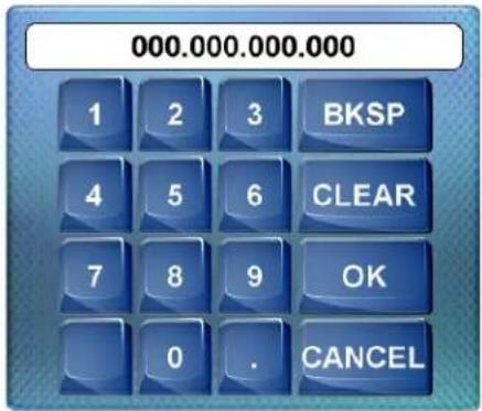
Touch CLEAR to remove any previous entry. Then enter the address required. Touch OK to accept the entry or CANCEL to cancel the entry. This hides the numeric keypad and returns the display to the "IP Address" screen.
On the "IP Address" screen, touch Save to keep the change or Cancel to cancel the change and return to the "Ethernet Setup Menu".
To enter (or change) the Static Primary DNS, Static Secondary DNS, Static Primary WINS or Static Secondary WINS, touch Edit DNS Servers >> on the "IP Address" screen. The "IP Address" screen changes to show these addresses, as shown in the illustration below.
"IP Address" Screen (Showing DNS and WINS Servers)
![IP Address << Edit IP Address Static Primary DNS: 000.000.000.000 [Touch Setting to Edit] Static Secondary DNS: 000.000.000.000 [Touch Setting to Edit] Static Primary WINS: 000.000.000.000 [Touch Setting to Edit] Static Secondary WINS: 000.000.000.000 [Touch Setting to Edit] Save Cancel](/content/2026/05/819977/images/8c9d34181762fd706c0a00ff7298946dd409ba36913b52e4d15f3cf231e72199.jpg)
Touch the appropriate button for the address to be entered (or changed). The numeric keypad opens.
Touch CLEAR to remove any previous entry. Then enter the address required. Touch OK to accept the entry or CANCEL to cancel the entry. This hides the numeric keypad and returns the display to the "IP Address" screen.
On the "IP Address" screen, touch Save to keep the change or Cancel to cancel the change and return to the "Ethernet Setup Menu". Touch << Edit IP Address to return to the previous "IP Address" screen.
IP Table
From the main "Setup" menu, touch IP Table to enter the "Control System Interface" menu, shown in the illustration below.
"Control System Interface" Menu
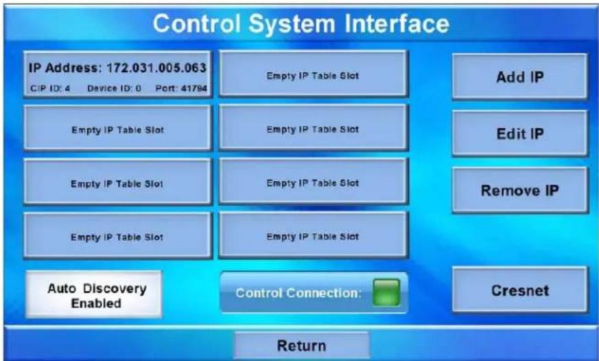
The “Control System Interface” menu contains buttons for eight IP Table slots as well as Add IP, Edit IP and Remove IP buttons to facilitate editing entries. Touch the Auto Discovery Enabled button to toggle to Auto Discover Disabled. A Control Connection indicator lights in green to show a control system connection. Touch Cresnet to enter a Cresnet ID and to enable or disable Cresnet. (Refer to “Cresnet” on page 20 for details.)
To add an IP entry to a blank slot, first touch one of the Empty IP Table Slot buttons, then touch Add IP. The "Edit IP Table Entry" screen is displayed, as shown below.
"Edit IP Table Entry" Screen
![Edit IP Table Entry IP Address / Hostname: 000.000.000.000 [Touch Setting to Edit] Port (41794): 41794 [Touch Setting to Edit] CIP ID: 3 [Touch Setting to Edit] Device ID: 0 [Touch Setting to Edit] Save Cancel](/content/2026/05/819977/images/a22f203389367acbe61493c3055b54152d9145ad70cde9e6df0e08d26255c157.jpg)
Touch the IP Address / Hostname button. The on-screen keyboard opens, as shown in the illustration below.
On-Screen Keyboard
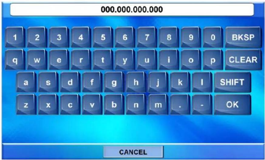
Touch CLEAR to remove any previous entry. Then enter the address required. Touch OK to accept the entry or CANCEL to cancel the entry. This hides the on-screen keyboard and returns the display to the "Edit IP Table Entry" screen.
On the "Edit IP Table Entry" screen, touch Save to keep the change or Cancel to cancel the change and return to the "Control System Interface" menu.
To edit the port, CIP ID or Device ID, touch the appropriate button. Touching the Port (41794) button opens the numeric keypad. Touching the CIP ID or Device ID buttons opens a hex keypad, shown in the illustration below.
Hex Keypad
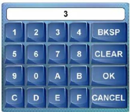
Touch CLEAR to remove any previous entry. Then enter the ID required. Touch OK to accept the entry or CANCEL to cancel the entry. This hides the hex keypad and returns the display to the "Edit IP Table Entry" screen.
From the “Control System Interface” menu, to edit or remove an IP entry, first touch the appropriate button containing the entry. Then touch Edit IP or Remove IP as appropriate. Editing an entry displays the “Edit IP Table Entry” screen (refer to illustration on page 16). Removing an entry displays a message saying Please
Confirm IP Table Entry Removal By Pressing the OK Button, as shown in the illustration below.
Confirm IP Table Entry Removal Screen
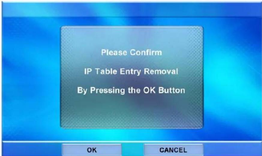
Touch OK to confirm the removal or touch CANCEL to cancel the removal. The display returns to the "Control System Interface" menu (refer to illustration on page 16).
On the "Control System Interface" menu, touch Return to go back to the main "Setup" menu.
Video
From the main "Setup" menu, touch Video to enter the "Video Setup" screen, shown in the illustration below.
"Video Setup" Screen
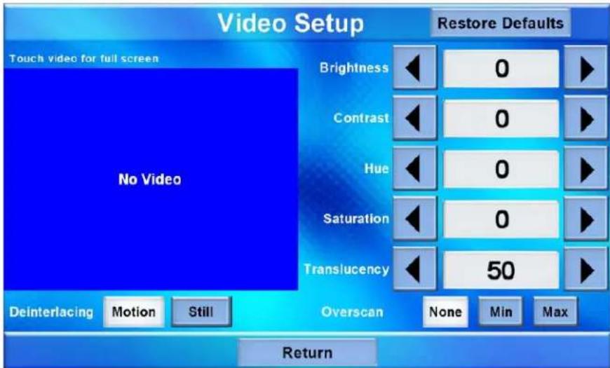
The "Video Setup" screen contains buttons for adjustment of Brightness, Contrast, Hue, Saturation, Translucency, type of Deinterlacing and amount of Overscan.
There is also a Restore Defaults button to return to factory settings and a window to display video.
Touch the video window for a full screen video display, as shown in the illustration below.
Full Screen Video Display
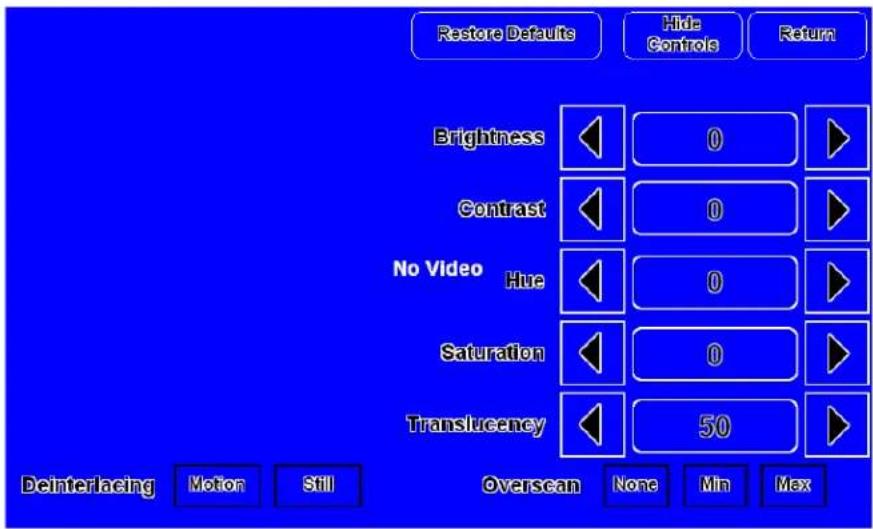
Touch Hide Controls to remove the controls. The button text changes to Show Controls. Touch Return to go back to the "Video Setup" screen. From the "Video Setup" screen, touch Return to go back to the main "Setup" menu.
Audio
From the main "Setup" menu, touch Audio to enter the "Audio Setup" screen, shown in the illustration below.
"Audio Setup" Screen
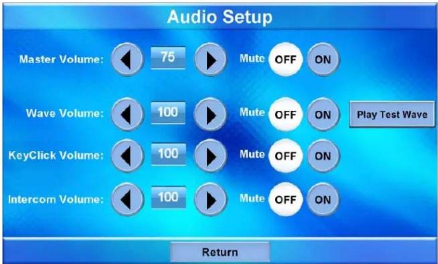
The “Audio Setup” screen contains buttons for adjustment or muting of Master Volume, Wave Volume, KeyClick Volume and Intercom Volume. There is also a Play Test Wave button. Touch Return to go back to the main “Setup” menu.
Cresnet
From the main "Setup" menu, touch Cresnet to enter the "Cresnet Interface" screen, shown in the illustration below.
"Cresnet Interface" Screen
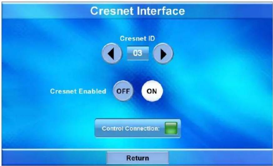
The “Cresnet Interface” screen contains buttons for setting the Cresnet ID and for enabling or disabling Cresnet. A Control Connection indicator lights in green to show a control system connection. Touch Return to go back to the main “Setup” menu.
Diagnostics
From the main “Setup” menu, touch Diagnostics to enter the “Diagnostics” menu, shown in the illustration below.
"Diagnostics" Menu
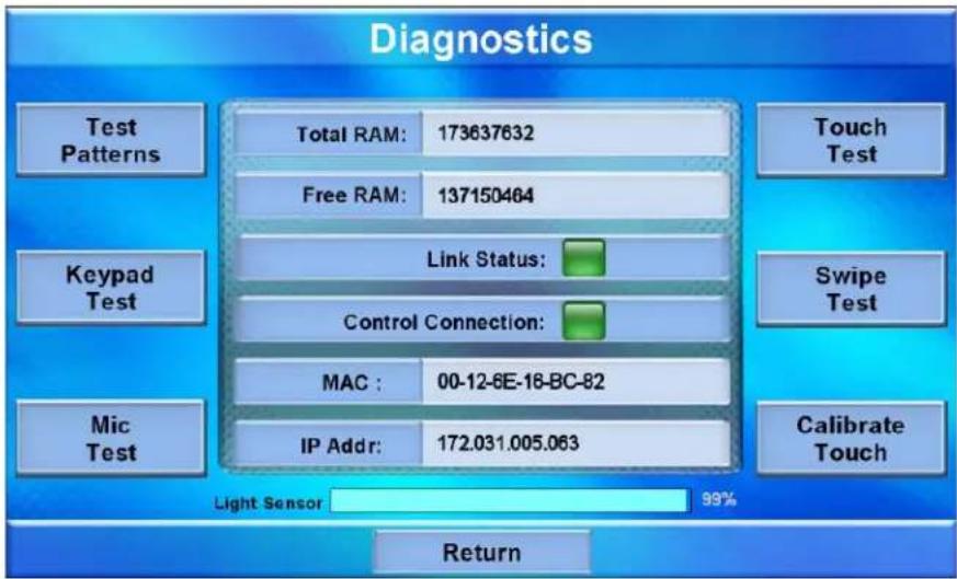
The “Diagnostics” menu contains buttons for Test Patterns, Touch Test, Keypad Test, Swipe Test, Mic Test and Calibrate Touch. This screen also displays Total RAM, Free RAM, as well as the current MAC and IP addresses. A Link Status indicator lights in green to show Ethernet activity and a Control Connection indicator lights in green to show a control system connection. The Light Sensor meter at the bottom of the screen provides indication of ambient light level.
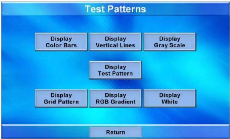
Touch Test Patterns to display a selection of test pattern options, as shown in the illustration below.
"Test Patterns" Screen
flowchart
graph TD
    A["Test Patterns"] --> B["Display Color Bars"]
    A --> C["Display Vertical Lines"]
    A --> D["Display Gray Scale"]
    A --> E["Display Test Pattern"]
    A --> F["Display Grid Pattern"]
    A --> G["Display RGB Gradient"]
    A --> H["Display White"]
    I["Return"] --> A
Test pattern options include Display Color Bars, Display Vertical Lines, Display Gray Scale, Display Test Pattern, Display Grid Pattern, Display RGB Gradient
and Display White. From any of these, touch the screen to return to the “Touch Patterns” screen. From the “Touch Patterns” screen, touch Return to go back to the “Diagnostics” menu.
From the “Diagnostics” menu, touch Touch Test to access touch screen calibration controls, as shown in the illustration below.
Touch Test Screen
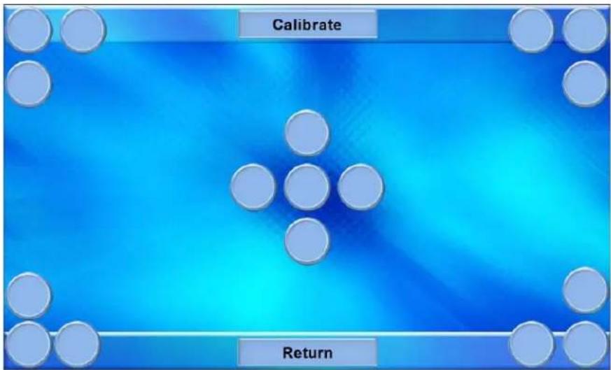
Touch Calibrate to initiate touch screen calibration. During touch screen calibration, a crosshair appears at the center of the screen. Touch the center of the crosshair, which then moves to the upper left part of the screen. Touch the center of the crosshair and it moves to another part of the screen. Continue touching the center of the crosshair at each new location until calibration is complete. After calibration, the display returns to the screen shown above. Touch Return to go back to the "Diagnostics" menu.
From the “Diagnostics” menu, touch Keypad Test to display the “Diagnostics – Keypad Test” screen, shown in the illustration below.
"Diagnostics - Keypad Test" Screen
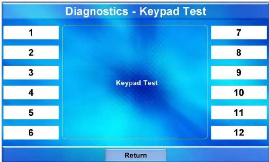
The “Diagnostics – Keypad Test” screen allows testing of the hard keys on the touch screen faceplate (assuming the button faceplate and not the no-button faceplate is installed). Pressing any of the hard keys results in its corresponding section of the screen changing (from a black number on a white background to a white number on a dark background) in recognition of the key press. Touch Return to go back to the “Diagnostics” menu.
From the “Diagnostics” menu, touch Swipe Test to display the “Swipe Test” screen, as shown in the illustration below.
"Swipe Test" Screen
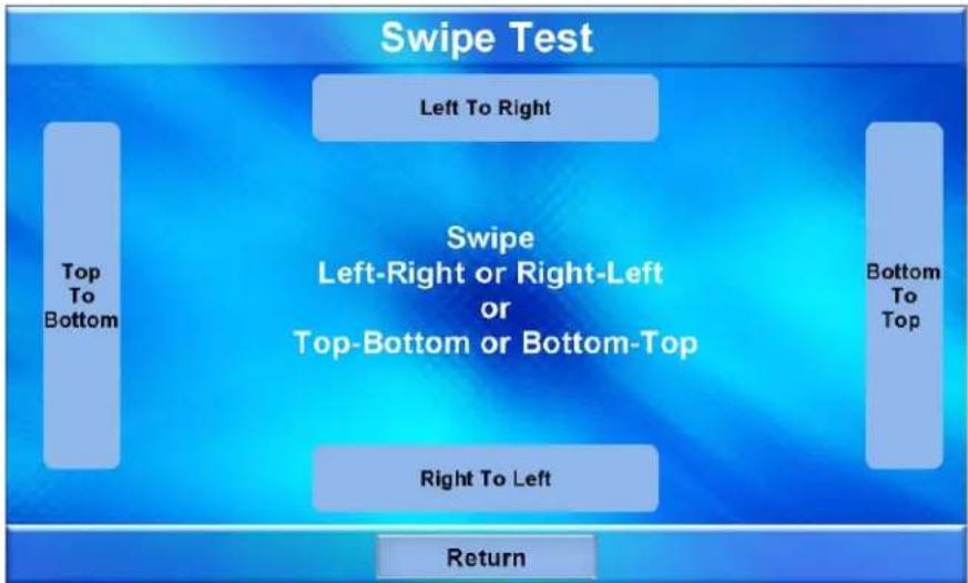
Swiping a finger on screen, left to right, right to left, top to bottom or bottom to top lights the appropriate indicator, showing the swipe was recognized. For more information on swiping, refer to "Swipe Gestures" on page 39. Touch Return to go back to the "Diagnostics" menu.
From the “Diagnostics” menu, touch Mic Test to display the “Diagnostics - Mic Test” screen, as shown in the illustration below.
"Diagnostics - Mic Test" Screen
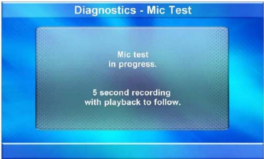
This screen performs a test of the TPMC-9L's built-in microphone. The touch screen records audio for five seconds and then plays back the recorded sound. Speak into the microphone on the front of the TPMC-9L and the recording is played back to confirm the microphone is functioning. When playback is finished, the display goes back to the "Diagnostics" menu.
The Calibrate Touch button on the “Diagnostics” menu initiates touch screen calibration, as does the Calibrate button on the Touch Test screen (refer to “Touch Test Screen” illustration on page 22).
From the "Diagnostics" menu, touch Return to go back to the main "Setup" menu.
About
From the main “Setup” menu, touch About to display the firmware version and operating system image version currently loaded on the TPMC-9L. Touch Return to go back to the main “Setup” menu.
Display
From the main “Setup” menu, touch Display to enter the “Display Settings” screen, shown in the illustration below.
"Display Settings" Screen
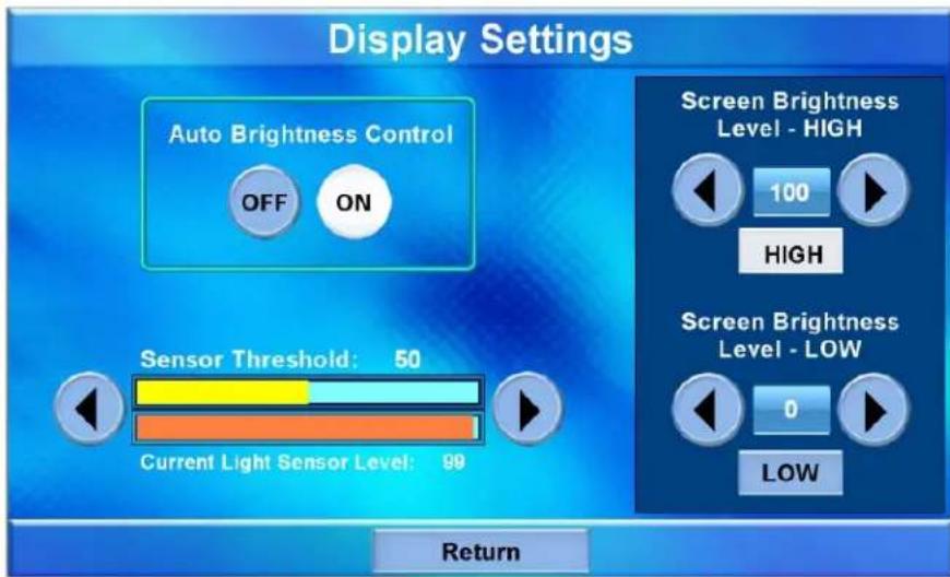
The “Display Settings” screen contains buttons for turning the TPMC-9L’s Auto Brightness Control on or off, controls for pre-setting the Screen Brightness Level – HIGH and Screen Brightness Level – LOW, as well as HIGH and LOW buttons for instantly activating these presets. In addition, there are controls to set the Sensor Threshold and a Current Light Sensor Level meter, like the one on the main “Diagnostics” menu (refer to “Diagnostics” which starts on page 21), to indicate ambient light level.
With the Auto Brightness Control set to OFF, the screen brightness is at the level set by the Screen Brightness controls (which appear in place of the Sensor Threshold and Current Light Sensor Level meters, as shown in the illustration that follows).
Screen Brightness Controls
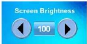
Use the Screen Brightness controls to adjust the relative level (0% to 100%) of current brightness. Use the Screen Brightness Level – HIGH and Screen Brightness Level – LOW controls to set the high and low preset brightness levels. Press the HIGH and LOW buttons to check each level.
With the Auto Brightness Control set to ON (the default), the Current Light Sensor Level meter changes to show the amount of ambient light reaching the sensor. The internal light sensor adjusts the brightness level to accommodate for the current room ambience. If the light level is above the threshold, the brightness changes to the high setting; if the level is below the threshold, brightness changes to the low setting.
Use the Sensor Threshold controls to set the level at which the Auto Brightness Control, when set to ON, adjusts screen brightness. The Sensor Level meter is provided as a guide to setting the threshold.
Touch Return to go back to the main "Setup" menu.
Keypad
From the main "Setup" menu, touch Keypad to enter the "Keypad Backlight Settings" screen, shown in the illustration below.
"Keypad Backlight Settings" Screen
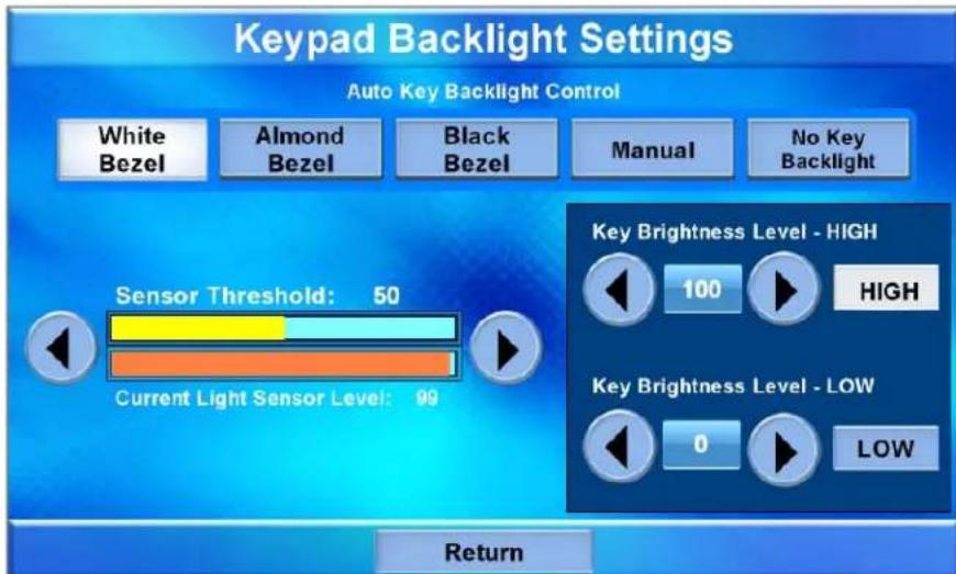
The “Keypad Backlight Settings” screen contains buttons for setting the TPMC-9L’s Auto Key Backlight Control for optimal performance to match the color bezel (white, almond or black), setting the control manually or turning off the key backlighting. There are also controls for pre-setting the Key Brightness Level – HIGH and Key Brightness Level – LOW, as well as HIGH and LOW buttons for instantly activating these presets. In addition, there are controls to set the Sensor Threshold and a Current Light Sensor Level meter, like the one on the main “Diagnostics” menu (refer to “Diagnostics” which starts on page 21) and on the “Display Settings” screen (refer to “Display” which starts on page 24), to indicate ambient light level.
With the Auto Key Backlight Control set to Manual, the key backlighting is at the level set by the Keypad Backlight Brightness controls (which appear in place of the Sensor Threshold and Current Light Sensor Level meters, as shown in the illustration that follows).
Keypad Backlight Brightness Controls
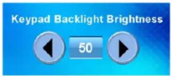
Use the Keypad Backlight Brightness controls to adjust the relative level (0% to 100%) of current key backlighting. Use the Key Brightness Level – HIGH and Key Brightness Level – LOW controls to set the high and low preset brightness levels. Press the HIGH and LOW buttons to check each level.
With the Auto Key Backlight Control set to White Bezel, Almond Bezel or Black Bezel, the Current Light Sensor Level meter changes to show the amount of ambient light reaching the sensor. The internal light sensor adjusts the key backlighting to accommodate for the current room ambience.
The threshold value is constant for all bezel colors. What the panel does when the sensor reading crosses the threshold differs for white, almond and black bezels.
- For white or almond bezels:
When the sensor level is below the threshold, the key backlight brightness is set to the high level.
When the sensor is above the threshold, the key backlight brightness is set to the low level.
- For black bezels:
When the sensor level is below the threshold, the key backlight brightness is set to the low level.
When the sensor is above the threshold, the key backlight brightness is set to the high level.
With the Auto Key Backlight Control set to No Key Backlight, the key backlight is turned off, regardless of the sensor reading or other settings.
Touch Return to go back to the main "Setup" menu.
Save & Reboot
From the main “Setup” menu, touch Save & Reboot to save all settings, exit the setup screens and return to the main project.
Mounting Options
The TPMC-9L installs simply and cleanly into existing or newly constructed walls, with an assortment of pre- and post-construction mounting options. The TPMC-9L is supplied with four screws and clips for post-construction installation. All available mounting options are listed in the following table. The options listed are sold separately from the touch screen.
Mounting Options for the TPMC-9L
| PRE-CONSTRUCTION OPTION | POST-CONSTRUCTION OPTION | MODEL NUMBER | DOCUMENT NUMBER |
| Back Box Kit - BB-9L 7031 | |||
| Wall Mount Kit - PMK-9L 7032 | |||
| Mud Ring Mount Kit - MMK-9L 7033 | |||
| Trim Ring Mount Kit - TMK-9L 7034 | |||
| - Wall Mount Kit with Mud Ring WMKM-9L | 7033 | ||
| - Wall Mount Kit with Trim Ring | WMKT-9L | 7034 |
NOTE: Pre-construction refers to framed walls prior to hanging drywall. Post-construction refers to framed walls with drywall hung.
NOTE: There is also a rack mount kit (RMK-9L) available for the TPMC-9L. Refer to the latest version of the RMK-9L Installation Guide (Doc. 7035).
If the BB-9L or PMK-9L are to be used and a touch screen is not available, the installer can either leave the hole in the mounting surface open (if permitted by local building codes) or attach the cover plate supplied with the mounting kit.
Touch Screen Mounting
Physical installation of the TPMC-9L without a mounting option includes mounting the unit to the wall and installing a faceplate. The only tools required for the procedures presented here are masking tape (or equivalent), a level, a gypsum board saw (or equivalent), and a #2 Phillips tip screwdriver. The following procedures are based on the use of the supplied screws and clips for post-construction installation.
Mounting in a Wall
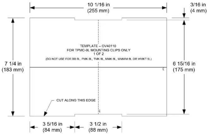
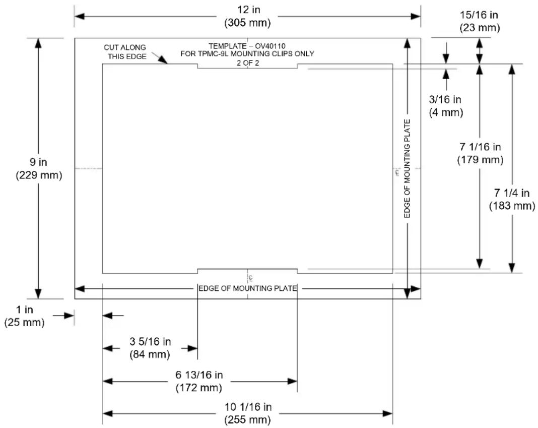
The TPMC-9L is designed to be mounted in a wall or lectern. Two overlay cutout templates (4511860) are supplied. One is in the shape of the required opening; the other is similar to a frame, with the inner area of the frame the shape of the required opening. (Refer to the illustrations on pages 28 and 29.) Use the template that is most convenient.
Mounting Parts Supplied with the TPMC-9L
| PART DESCRIPTION PART NUMBER QUANTITY | |
| Metal Mounting Clip 2014237 4 | |
| Overlay Template Cutout 4511860 1 | |
| Connector Plug, 2-pin 2003574 1 | |
| Connector Plug, 3-pin 2003575 1 | |
| Connector Plug, 4-pin 2003576 1 | |
| Screw, #6-AB x 2-1/2", Pan Head 2014276 4 | |
| Screw, #04-40 x 2", Pan Head* 2018793 4 | |
* The #04-40 x 2" screws are for use with TPMC-9L mounting kits such as the BB-9L (sold separately).
NOTE: The following drawings are not to scale. Do not attempt to use them to prepare the hole in the mounting surface.
TPMC-9L Cutout Dimensions (4511860, 1 of 2)
TPMC-9L Cutout Dimensions (4511860, 2 of 2)
- Locate an area on the wall that is free of miscellaneous wiring and studs.
- Make a small hole near the middle of the designated site, and verify that the location is suitable.
- Using masking tape (or equivalent), fasten the template to the wall; verify that the template is level, and trace the opening shape on the wall.
- Remove the template, and then cut out and remove the traced shape to produce the required opening.
NOTE: Before inserting the TPMC-9L in the mounting hole, ensure that all required cables have been installed in the wall.
- Install the four supplied #6-AB x 2-1/2" screws and mounting clips as shown in the following diagram (two on the top and two on the bottom).
a. Insert the screws through the touch screen flange and then through the larger hole in the mounting clip.
b. Thread the screws through the smaller hole in the mounting clips and tighten the screws only enough that the mounting clips are brought flush with the rear of the touch screen flange. Do not compress the mounting clips at this time.
Attaching the Screws and Mounting Clips

-
Connect the Cresnet cable, using the supplied mating connector, to the Cresnet port; attach the Ethernet cable, if required. Attach video cables, using the supplied mating connectors and position the TPMC-9L in the mounting hole. Refer to "Hardware Hookup" which starts on page 31.
-
Tighten the mounting screws evenly and only enough to compress the mounting clips and secure the TPMC-9L squarely in the mounting surface. Do not over-tighten the screws.
Installing the Faceplate
Use the Crestron Engraver software package to obtain a custom-engraved faceplate for the TPMC-9L. Install the faceplate as follows.
-
Carefully position the faceplate over the face of the touch screen.
-
Ensure that the faceplate is oriented properly and press against the TPMC-9L until the faceplate snaps into place.
Touch Screen Removal
If it is necessary to remove the touch screen after it has been installed into a mounting surface, complete the following steps in the order provided to remove the touch screen. The only tool required is a #2 Phillips tip screwdriver.
- Lift one edge of the faceplate to free it from the touch screen and lift it off. Do not apply excessive pressure to the touch screen.
- Loosen and remove the screws that secure touch screen to the mounting option in use.
- Using equal pressure, carefully remove the touch screen from the opening.
If necessary, secure and label the attached cables before disconnecting them from the back of the touch screen.
Hardware Hookup
Ventilation
The TPMC-9L should be used in a well-ventilated area. The venting holes should not be obstructed under any circumstances. If the TPMC-9L is hot to the touch, consider using forced air ventilation.
To prevent overheating, do not operate this product in an area that exceeds the environmental temperature range listed in the table of specifications. Consideration must be given if installed in a closed or multi-unit rack assembly since the ambient operating temperature of the environment may be greater than the ambient room temperature. Contact with thermal insulating materials should be avoided on all sides of the unit.
Connect the Device
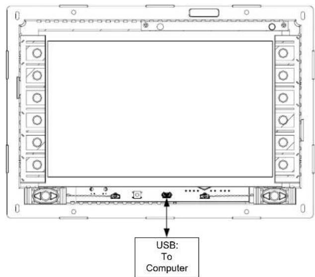
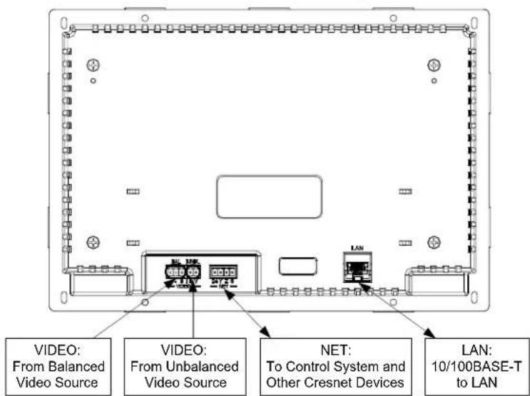
Make the necessary connections as called out in the illustration on the following page. Refer to “Network Wiring” on page 12 before attaching the 4-position terminal block connector. Apply power after all connections have been made.
When making connections to the TPMC-9L, use Crestron power supplies for Crestron equipment.
Hardware Connections for the TPMC-9L (Front View)
Hardware Connections for the TPMC-9L (Rear View)
Recommended Cleaning
Keep the surface of the touch screen free of dirt, dust or other materials that could degrade optical properties. Long term contact with abrasive materials can scratch the surface, which may detrimentally affect image quality.
For best cleaning results, use a clean, damp, non-abrasive cloth with any commercially available non-ammonia glass cleaner. Faceplates may not provide a complete watertight seal. Therefore, apply cleaning solution to the cloth rather than the surface of the touch screen. Wipe touch screen clean and avoid getting moisture beneath the faceplate.
CAUTION: Do not apply excessive pressure to the touch screen display during handling. Doing so can crack the screen and damage the touch screen.
Programming Software
Have a question or comment about Crestron software?
Answers to frequently asked questions (FAQs) can be viewed in the Online Help section of the Crestron Web site. To post a question or view questions submitted to Crestron's True Blue Support, log in at www.crestron.com/onlinehelp. First-time users must establish a user account to fully benefit from all available features.
Software Requirements for the PC
NOTE: The latest software can be downloaded from the Crestron Web site (www.crestron.com/software).
Crestron provides an assortment of Windows ^® -based software tools to develop a customized system. Use SystemBuilder ^™ or SIMPL Windows to create a program to control the TPMC-9L.
Programming with Crestron SystemBuilder
SystemBuilder is a comprehensive programming environment. Appropriate for most systems, it can quickly and easily generate a complete working program including both control processor logic and touch screen graphics.
Programming with SIMPL Windows
NOTE: While SIMPL Windows can be used to program the TPMC-9L, it is recommended to use SystemBuilder for configuring a system.
SIMPL Windows is Crestron's premier software for programming Crestron control systems. It is organized into two separate but equally important “Managers”: Configuration and Program.
Configuration Manager
Configuration Manager is the view where programmers “build” a Crestron control system by selecting hardware from the Device Library.
- The TPMC-9L must first be incorporated into the system.
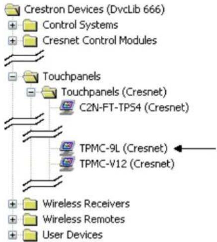
a. To incorporate the TPMC-9L (Cresnet) into the system, drag the TPMC-9L from the Touchpanels | Touchpanels (Cresnet) folder of the Device Library and drop it in the System Views.
Locating the TPMC-9L (Cresnet) in the Device Library
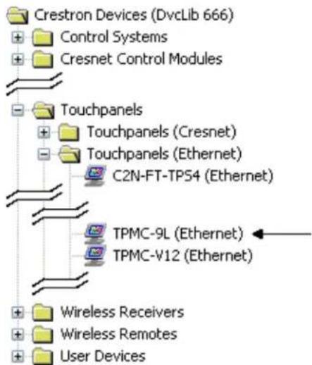
b. To incorporate the TPMC-9L (Ethernet) into the system, drag the TPMC-9L from the Touchpanels | Touchpanels (Ethernet) folder of the Device Library and drop it in the System Views.
Locating the TPMC-9L (Ethernet) in the Device Library
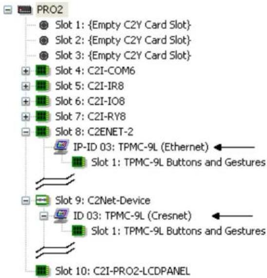
The system tree of the control system displays the device in the appropriate slot(s) with a default Net ID or IP ID as shown in the following illustration. Below the TPMC-9L in the illustration, the "TPMC-9L Buttons and Gestures" extender is visible. The extender provides a set of signals that allow programmers to quickly identify when a hard key is pressed or released or when there is gesture input on the touch screen.
NOTE: In the following illustration, there is both an Ethernet device in Slot 8 and a Cresnet device in Slot 9. It is possible to have both types of device attached to a control system as long as the control system has either a built-in or expansion Ethernet interface. If Cresnet operation is desired, the IP table for the TPMC-9L must be empty.
C2ENET-2 and C2Net Devices, Slot 8 and 9
- If additional TPMC-9L devices are to be added, repeat step 1 for each device. Each TPMC-9L is assigned a different Net ID or IP ID number as it is added.
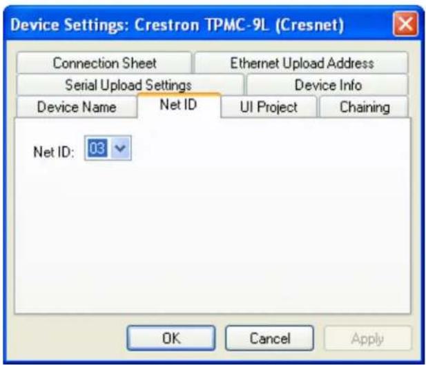
- If necessary, double click a device to open the "Device Settings" window and change the Net ID or IP ID, as shown in the following illustrations.
"Device Settings: Crestron TPMC-9L (Cresnet)" Window
"Device Settings: Crestron TPMC-9L (Ethernet)" Window
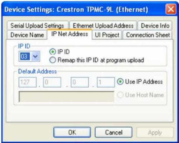
NOTE: The ID code specified in the SIMPL Windows program must match the Net ID or IP ID of each unit. Refer to "Identity Code" on page 12.
Program Manager
Program Manager is the view where programmers "program" a Crestron control system by assigning signals to symbols.
The symbol can be viewed by double clicking on the icon or dragging it into Detail View. Each signal in the symbol is described in the SIMPL Windows help file (F1).
Programming with VisionTools
Touch screen pages should be created in Crestron VisionTools® (VT Pro-e®) to allow accessing the embedded applications, switching of source signals to desired outputs as well as selection of the system mode. There are no special programming requirements to use the functions of the TPMC-9L in a room-control system.
Multi-Mode Objects
Multi-mode objects offer high-performance programming!
The single most-advanced VT Pro-e high-performance programming technique involving the TPMC-9L is the concept of multi-mode objects. A multi-mode object (i.e., button, legend, etc.) is an object drawn on a VT Pro-e page that can have one or more active and inactive visible settings (modes).
For examples, refer to www.crestron.com/exampleprograms and search for multi-mode object examples. This file contains the VT Pro-c touch screen files and SIMPL Windows files that illustrate the high-performance capabilities of multi-mode objects.
WAV File Audio Messages
The TPMC-9L touch screens are capable of playing audio messages as system prompts and responses. These files are recorded as WAV files on a PC using an audio utility such as Sound Recorder that is packaged with Microsoft® Windows. Files from other sources may also be converted to an acceptable format by using this or a similar utility. Many other audio utilities are available commercially or as shareware. The TPMC-9L touch screens accept the following WAV file formats: PCM, 8 & 16 bit, 8 – 44.1 kHz, mono & stereo. For more information about how
to use Sound Recorder, refer to its User's Guide and extensive help information provided with the software. Also refer to the help file in VT Pro-e to learn how to use its audio tool, Sound Manager, to attach WAV files to a touch screen project.
Pre-recorded WAV files for voice prompts and responses are available from Crestron. These files can be stored into and programmed for use in the touch screen directly or may be edited with the Sound Recorder. For example, the individual files can be combined to create custom messages.
NOTE: Touch screen WAV files can be obtained from the Wave LC Library of the Crestron FTP site.
Bit Depth and File Size
A balance of performance and quality can be achieved by using VT Pro-e to configure the size of graphics in a project. Read this section to learn about bit depth and how to maximize the quality and performance of a TPMC-9L project.
Bit depth refers to the number of memory bits used to store color data for each pixel in a raster image. A touch screen raster image consists of a rectangular grid of picture elements (pixels). Each pixel uses the same amount of memory to store its color data. The amount of memory is called the bit depth of the image.
Greater bit depths are required to represent finer gradations of color. Increasing bit depth necessarily increases file size. A black and white drawing requires only one bit per pixel to store all the available color information. Using a 32-bit per pixel bit depth for a black and white image increases the file size 32 times without adding anything to the black and white image quality.
In an 8-bit per pixel system, the associated 8-bits of video memory for every screen pixel contain a value referring to a location in an 8-bit color table. In this way any one of the specific 256 color table locations is assigned to a pixel.
A 16-bit highcolor system is considered sufficient to provide life-like colors. It is encoded using 5-bits to represent red, 5-bits to represent blue and (since the human eye is more sensitive to the color green) 6-bits to represent 64 levels of green. These can therefore be combined to provide 65,536 mixed colors (32 x 32 x 64 = 65,536).
In a 24-bit graphics display, the video memory allocates 24 bits for each pixel on the screen enabling each pixel to take on any one of a possible 16.7 million colors. Each 24-bit value is composed of 8-bits for red, 8-bits for green and 8-bits for blue. These triplets of 8-bit values are also referred to as the red, green and blue color planes. A 24-bit image is actually composed of three component images which combine to create the truecolor picture. The reason this is called truecolor is that this is near the maximum number of colors the human eye is able to detect.
Truecolor images are sometimes represented by a 32-bit value. The extra 8-bits do not enhance the precision of the color representation but act as an alpha channel that represents pixel translucence. The 32-bit truecolor has become popular on the computer desktop to provide effects such as translucent windows, fading menus and shadows.
In graphics intensive applications such as touch screens, raising or lowering the color depth of the displayed graphics can achieve a balance of performance and quality. Lower color depths do not require as much frame buffer memory or display bandwidth, allowing them to be generated and displayed more quickly. Increasing color depth results in higher color quality at the expense of display speed and responsiveness. By using mostly 8-bit or 16-bit graphics and holding 32-bit graphics to a minimum (e.g., for a family photo, etc.), a sophisticated project can be created that fits in the memory space provided while the touch screen remains very responsive.
Relationship of Bits to Colors
| NUMBER OF BITS | NUMBER OF COLORS |
| 1 bit Black and White | |
| 2 bits 4 Colors | |
| 4 bits 16 Colors | |
| 8 bits 256 Colors | |
| 16 bits 65,536 Colors (Highcolor) | |
| 24 bits 16.7 million Colors (Truecolor) | |
| 32 bits 16.7 million Colors plus Transparency | |
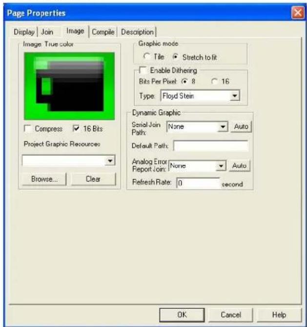
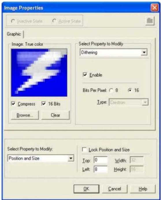
When creating a VT Pro-e project, the image size can be compressed and reduced in the "Page Properties" dialog box for the entire page. The image size can also be compressed and reduced using the "Image Properties" dialog box. A reduction in image size saves a considerable amount of memory space for the project.
In VT Pro-e, the Compress checkbox permits the image to be compressed when compiling. The 16 Bits checkbox converts a 24-bit or 32-bit image to 16 bits. This conversion to a 16-bit image may cause the loss of some subtle shading. To compensate for this, use the dithering to simulate the original shading. Check the image with each of the available dithering types to determine which delivers the best quality image.
Dithering type selection can be accessed from the "Page Properties" or "Image Properties" dialog boxes in VT-Pro-e. Refer to the following illustrations.
VT Pro-e "Page Properties" Dialog Box
- Bit Depth Selection
VT Pro-e "Image Properties" Dialog Box - Bit Depth Selection
MultiByte International Characters
Most languages use a single byte of eight bits to represent a character, e.g., English, French, German, Hebrew, Russian, Thai, etc.
Multibyte character fonts require more than the usual eight bits to specify a character. This occurs when a language has more than 256 characters ( 2^8 ) in a font. For example, Chinese fonts contain several thousand characters. Other multibyte languages include Japanese and Korean.
There are two separate applications with multibyte characters – static text on buttons and indirect text on buttons. No touch screen firmware changes are required in either case.
Indirect text on a button is entered in VT Pro-e and the actual string to be displayed is entered in SIMPL Windows. As of this publication date only completely single byte or completely multibyte strings may be entered or they can not be compiled correctly in SIMPL Windows. In other words, Chinese characters cannot be interspersed with numbers. Enter Chinese characters or numbers in separate strings or pad each number with “\x00” to make it multibyte and then combine it with Chinese characters in the same string.
Of course, the workaround of showing a graphic that displays the string but which is not dynamic, can always be used. To compile and use multibyte characters it is essential that the operating system understand the language. Some versions of Windows are available in many international languages and add-on software is available for other versions.
Swipe Gestures
Swipe gestures are assigned using the “Hard Button Manager” in VT Pro-e. They can be assigned at the project level or at the individual page level. As with regular buttons, whether virtual ones on the screen or physical hard buttons, these can be assigned joins or local page flips.
When programming for swipe gestures, it is a good idea to leave an area of the screen free of touchable objects (e.g., buttons, sliders or other controls). Swipe gestures can not work over touchable objects, which take precedence over swipes.
Push Button Programming
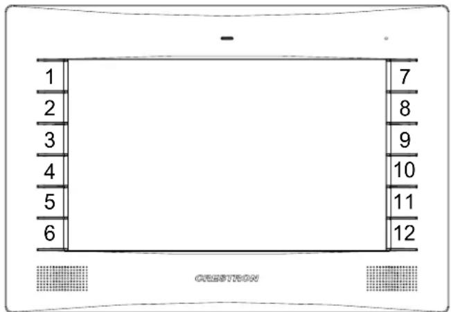
The twelve push buttons that flank the display can be programmed to access any frequently used command. Each button has a permanently fixed digital join number. The sequence of digital join numbers is (top to bottom, left to right) 1 through 6 and 7 through 12. Refer to the following illustration. A description for each button signal is given in the SIMPL Windows help file (F1).
Push Button Layout and Join Number Assignment
Uploading and Upgrading
Crestron recommends using the latest programming software and that each device contains the latest firmware to take advantage of the most recently released features. However, before attempting to upload or upgrade it is necessary to establish communication. Once communication has been established, files (for example, programs, projects or firmware) can be transferred to the control system (and/or device). Finally, program checks can be performed (such as changing the device ID or creating an IP table) to ensure proper functioning.
Establishing Communication
NOTE: For PCs running Windows 2000 or XP, ActiveSync 4.5 or later is required for Toolbox to communicate with the TPMC-9L via USB to upload firmware and display lists. Download and install ActiveSync from the Microsoft Web site (www.microsoft.com/windowsmobile/en-us/help/synchronize/device-synch.mspx).
PCs running Windows Vista or 7 require Windows Mobile Device Center for communication with Toolbox. Download and install Windows Mobile Device Center (WMDC) from the Microsoft Web site (www.microsoft.com/windowsmobile/devicecenter.mspx).
Use Crestron Toolbox for communicating with the TPMC-9L; refer to the Crestron Toolbox help file for details. There are three methods of communication: indirect, TCP/IP and USB.
Indirect
Indirect Communication

flowchart
graph LR
    A["PC Running Crestron Toolbox"] -->|Serial, LAN or USB| B["Control System"]
    B -->|Cresnet| C["TPMC-9L"]
TPMC-9L connects to control system via Cresnet:
- Establish communication between the PC and the control system as described in the latest version of the 2-Series Control Systems Reference Guide (Doc. 6256).
- Use the Address Book in Crestron Toolbox to create an entry for the TPMC-9L using the expected communication protocol (Indirect). Select the Cresnet ID of the TPMC-9L and the address book entry of the control system that is connected to the TPMC-9L.
- Display the TPMC-9L's "System Info" window (click the icon); communications are confirmed when the device information is displayed.
TCP/IP
Ethernet Communication

flowchart
graph LR
    A["PC Running Crestron Toolbox"] <--> B["LAN"]
    B --> C["TPMC-9L"]
The TPMC-9L connects to PC via Ethernet:
- Confirm Ethernet connection between TPMC-9L and PC. If connecting through a hub or router, use CAT5 straight through cables with 8-pin RJ-45 connectors. Alternatively, use a CAT5 crossover cable to connect the two LAN ports directly without using a hub or router.
- Use the Device Discovery Tool in Crestron Toolbox to detect all Ethernet devices on the network and their IP configuration. The tool is available in Toolbox version 1.15.143 or later.
- Use the Address Book in Crestron Toolbox to create an entry for the TPMC-9L with the TPMC-9L's TCP/IP communication parameters.
- Display the "System Info" window (click the icon) and select the TPMC-9L entry from the Address Book or the Address Book drop-down menu.
USB
USB Communication

flowchart
graph LR
    A["PC Running Crestron Toolbox"] <-->|USB| B["TPMC-9L"]
The USB port on the TPMC-9L connects to the USB port on the PC:
- Use a USB cable to connect the TPMC-9L to a PC running the Crestron Toolbox.
- Open the "System Info" window; click the "Enter an address ..." icon (pencil) to display the "Edit Address" window.
- Select USB as the connection type, and select "TPMC-9L" from the Device Type drop down list (click OK when the "Warning" notice appears).
Programs, Projects and Firmware
Program, project or firmware files may be distributed from programmers to installers or from Crestron to dealers. Firmware upgrades are available from the Crestron Web site as new features are developed after product releases. One has the option to upload programs and projects via the programming software or to upload and upgrade via the Crestron Toolbox. For details on uploading and upgrading, refer to the SIMPL Windows help file, VT Pro-e help file or the Crestron Toolbox help file.
SIMPL Windows
If a SIMPL Windows program is provided, it can be uploaded to the control system using SIMPL Windows or Crestron Toolbox.
VT Pro-e
Upload the VT Pro-e file to the touch screen using VT Pro-e or Crestron Toolbox.
Firmware
Check the Crestron Web site to find the latest firmware. (New users may be required to register to obtain access to certain areas of the site, including the FTP site.)
Upgrade TPMC-9L firmware via Crestron Toolbox.
- Establish communication with the TPMC-9L and display the "System Info" window.
- Select Functions | Firmware... to upgrade the TPMC-9L firmware.
Program Checks
Actions that can be performed on the TPMC-9L vary depending on whether it is connected via Cresnet or Ethernet.
Cresnet Connections
For Cresnet connections, using Crestron Toolbox, display the network device tree (Tools | Network Device Tree View) to show all network devices connected to the control system. Right-click on the TPMC-9L to display actions that can be performed on the TPMC-9L.
Ethernet Connections
For Ethernet connections, display the "System Info" window (click the i icon) and select the Functions menu to display actions that can be performed on the TPMC-9L.
Be sure to use the internal setup menu (refer to "IP Table" which starts on page 16) or Crestron Toolbox to create the TPMC-9L IP table. In Toolbox:
- Select Functions | IP Table Setup.
- Add, modify or delete entries in the IP table.
- A defined IP table can be saved to a file or sent to the device.
Edit the control system's IP table to include an entry for the TPMC-9L. The entry should list the TPMC-9L's IP ID (specified on the TPMC-9L's IP table) and the internal gateway IP address 127.0.0.1.
Problem Solving
Troubleshooting
The following table provides corrective action for possible trouble situations. If further assistance is required, please contact a Crestron customer service representative.
TPMC-9L Troubleshooting
| TROUBLE POSSIBLE CAUSE(S) CORRECTIVE ACTION | ||
| Device does not function. | Device is not communicating with the network. | Use Crestron Toolbox to poll the network. Verify network connection to the device. |
| Device is not receiving power from a Crestron power source. | Use the provided Crestron power source. Verify connections. | |
| Device is not receiving sufficient power. | Use the Crestron Power Calculator to help calculate how much power is needed for the system. | |
| Touch screen is not responding. | Touch screen Net ID is not set to match the Net ID in the SIMPL program. | Use Crestron Toolbox to poll the network. Verify the Net ID for the touch screen is properly set to match the Net ID in the SIMPL program. |
| Touch screen Net ID is not unique; two or more units share the same ID. | Use Crestron Toolbox to poll the network and verity that each ID is used only once. | |
| No IP address configured/obtained on the TPMC-9L. | Use the internal setup menu (refer to “IP Table” which starts on page 16) or Crestron Toolbox to create/verify Ethernet settings. | |
| Invalid control system IP address / IP ID set up on the TPMC-9L. | The IP address (or host name) for the control system is invalid or the IP ID does not match the one defined in the SIMPL program. Refer to “Ethernet” which starts on page 14 and to “IP Table” which starts on page 16 to define IP addresses. | |
| Touch screen display is dark. | Standby timeout has elapsed. | Touch the screen to reactivate. |
| Unexpected response from touch screen. | Touch screen is incorrectly calibrated. | Recalibrate the touch screen (refer to “Diagnostics” which starts on page 21). |
| TPMC-9L boots up in setup screens every time. | Invalid VT Pro-e project or no VT Pro-e project is loaded. | Load/reload VT Pro-e project using the Toolbox. |
Check Network Wiring
Use the Right Wire
To ensure optimum performance over the full range of the installation topology, use Crestron Certified Wire only. Failure to do so may incur additional charges if support is required to identify performance deficiencies because of using improper wire.
Calculate Power
CAUTION: Use only Crestron power supplies for Crestron equipment. Failure to do so could cause equipment damage or void the Crestron warranty.
CAUTION: Provide sufficient power to the system. Insufficient power can lead to unpredictable results or damage to the equipment. Use the Crestron Power Calculator to help calculate how much power is needed for the system (www.crestron.com/calculators).
When calculating the length of wire for a particular Cresnet run, the wire gauge and the Cresnet power usage of each network unit to be connected must be taken into consideration. Use Crestron Certified Wire only. If Cresnet units are to be daisy chained on the run, the Cresnet power usage of each network unit to be daisy chained must be added together to determine the Cresnet power usage of the entire chain. If the unit is run from a Crestron system power supply network port, the Cresnet power usage of that unit is the Cresnet power usage of the entire run. The wire gauge and the Cresnet power usage of the run should be used in the following equation to calculate the cable length value on the equation's left side.
Cable Length Equation
$$ L < \frac {4 0 , 0 0 0}{R \times P} \boxed { \begin{array}{l} \text {Where: L = Length of run (or chain) in feet} \ R = 6 \text {Ohms (Crestron Certified Wire: 18 AWG (0.75 mm)} \ \text {or 1.6 Ohms (Cresnet HP: 12 AWG (4 mm} ^ {2}) \ P = \text {Cresnet power usage of entire run (or chain)} \end{array} } $$
Make sure the cable length value is less than the value calculated on the right side of the equation. For example, a Cresnet run using 18 AWG Crestron Certified Wire and drawing 20 watts should not have a length of run more than 333 feet (101 meters). If Cresnet HP is used for the same run, its length could extend to 1250 feet (381 meters).
NOTE: All Crestron certified Cresnet wiring must consist of two twisted pairs. One twisted pair is the +24V conductor and the GND conductor and the other twisted pair is the Y conductor and the Z conductor.
Strip and Tin Wire
When daisy chaining Cresnet units, strip the ends of the wires carefully to avoid nicking the conductors. Twist together the ends of the wires that share a pin on the network connector and tin the twisted connection. Apply solder only to the ends of the twisted wires. Avoid tinning too far up the wires or the end becomes brittle. Insert the tinned connection into the Cresnet connector and tighten the retaining screw. Repeat the procedure for the other three conductors.
Add Hubs
Use of a Cresnet Hub/Repeater (CNXHUB) is advised whenever the number of Cresnet devices on a network exceeds 20 or when the combined total length of Cresnet cable exceeds 3000 feet (914 meters).
Reference Documents
The latest version of all documents mentioned within the guide can be obtained from the Crestron Web site (www.crestron.com/manuals).
List of Related Reference Documents
| DOCUMENT TITLE |
| 2-Series Control Systems Reference Guide |
| BB-9L Pre-Construction Wall Mount Back Box |
| Crestron e-Control Reference Guide |
| MMK-9L & WMKM-9L Mud Mount Kits |
| PMK-9L Pre-Construction Wall Mount Kit |
| RMK-9L Rack Mount Kit |
| TMK-9L & WMKT-9L Trim Ring Mount Kits |
Further Inquiries
To locate specific information or resolve questions after reviewing this guide, contact Crestron's True Blue Support at 1-888-CRESTRON [1-888-273-7876] or refer to the listing of Crestron worldwide offices on the Crestron Web site (www.crestron.com/offices) for assistance within a particular geographic region.
To post a question about Crestron products, log onto the Online Help section of the Crestron Web site (www.crestron.com/onlinehelp). First-time users must establish a user account to fully benefit from all available features.
Future Updates
As Crestron improves functions, adds new features and extends the capabilities of the TPMC-9L, additional information may be made available as manual updates. These updates are solely electronic and serve as intermediary supplements prior to the release of a complete technical documentation revision.
Check the Crestron Web site periodically for manual update availability and its relevance. Updates are identified as an “Addendum” in the Download column.
Return and Warranty Policies
Merchandise Returns / Repair Service
- No merchandise may be returned for credit, exchange or service without prior authorization from Crestron. To obtain warranty service for Crestron products, contact an authorized Crestron dealer. Only authorized Crestron dealers may contact the factory and request an RMA (Return Merchandise Authorization) number. Enclose a note specifying the nature of the problem, name and phone number of contact person, RMA number and return address.
- Products may be returned for credit, exchange or service with a Crestron Return Merchandise Authorization (RMA) number. Authorized returns must be shipped freight prepaid to Crestron, 6 Volvo Drive, Rockleigh, N.J. or its authorized subsidiaries, with RMA number clearly marked on the outside of all cartons. Shipments arriving freight collect or without an RMA number shall be subject to refusal. Crestron reserves the right in its sole and absolute discretion to charge a 15% restocking fee plus shipping costs on any products returned with an RMA.
- Return freight charges following repair of items under warranty shall be paid by Crestron, shipping by standard ground carrier. In the event repairs are found to be non-warranty, return freight costs shall be paid by the purchaser.
Crestron Limited Warranty
Crestron Electronics, Inc. warrants its products to be free from manufacturing defects in materials and workmanship under normal use for a period of three (3) years from the date of purchase from Crestron, with the following exceptions: disk drives and any other moving or rotating mechanical parts, pan/tilt heads and power supplies are covered for a period of one (1) year; touch screen display and overlay components are covered for 90 days; batteries and incandescent lamps are not covered.
This warranty extends to products purchased directly from Crestron or an authorized Crestron dealer. Purchasers should inquire of the dealer regarding the nature and extent of the dealer's warranty, if any.
Crestron shall not be liable to honor the terms of this warranty if the product has been used in any application other than that for which it was intended or if it has been subjected to misuse, accidental damage, modification or improper installation procedures. Furthermore, this warranty does not cover any product that has had the serial number altered, defaced or removed.
This warranty shall be the sole and exclusive remedy to the original purchaser. In no event shall Crestron be liable for incidental or consequential damages of any kind (property or economic damages inclusive) arising from the sale or use of this equipment. Crestron is not liable for any claim made by a third party or made by the purchaser for a third party.
Crestron shall, at its option, repair or replace any product found defective, without charge for parts or labor. Repaired or replaced equipment and parts supplied under this warranty shall be covered only by the unexpired portion of the warranty.
Except as expressly set forth in this warranty, Crestron makes no other warranties, expressed or implied, nor authorizes any other party to offer any warranty, including any implied warranties of merchantability or fitness for a particular purpose. Any implied warranties that may be imposed by law are limited to the terms of this limited warranty. This warranty statement supersedes all previous warranties.
Crestron software, including without limitation, product development software and product operating system software is licensed to Crestron dealers and Crestron Authorized Independent Programmers (CAIPs) under a limited non-exclusive, non-transferable license pursuant to a separate end-user license agreement. The terms of this end user license agreement can be found on the Crestron Web site at www.crestron.com/legal/software_license_agreement.

CRESTRON®
Crestron Electronics, Inc. Operations & Installation Guide - DOC. 7030B
15 Volvo Drive Rockleigh, NJ 07647 (2028354)
Tel: 888.CRESTRON 08.12
Fax: 201.767.7576 Specifications subject to
www.crestron.com change without notice.

- Regulatory Compliance
- Federal Communications Commission (FCC) Compliance Statement
- Industry Canada (IC) Compliance Statement
- Isys® 9" Wall Mount Touch Screen: TPMC-9L
- Introduction
- Features and Functions
- Advanced Touch Screen Control
- Powered by Core 3
- Integrated Video
- Rava SIP Intercom
- Audio Feedback
- Push Button Options
- Auto-Brightness Control
- High Speed Connectivity
- Versatile Flush Mount Design
- Applications
- Specifications
- Physical Description
- Setup
- Network Wiring
- Identity Code
- Net ID
- IP ID
- Configuring the Touch Screen
- Ethernet
- IP Table
- Video
- Audio
- Cresnet
- Diagnostics
- Touch Test Screen
- "Diagnostics - Keypad Test" Screen
- About
- Display
- Screen Brightness Controls
- Keypad
- "Keypad Backlight Settings" Screen
- Save & Reboot
- Mounting Options
- Touch Screen Mounting
- Mounting in a Wall
- Installing the Faceplate
- Touch Screen Removal
- Hardware Hookup
- Ventilation
- Connect the Device
- Recommended Cleaning
- Programming Software
- Software Requirements for the PC
- Programming with Crestron SystemBuilder
- Programming with SIMPL Windows
- Program Manager
- Programming with VisionTools
- Multi-Mode Objects
- WAV File Audio Messages
- Bit Depth and File Size
- MultiByte International Characters
- Swipe Gestures
- Push Button Programming
- Uploading and Upgrading
- Establishing Communication
- Indirect
- Indirect Communication
- TCP/IP
- Ethernet Communication
- USB
- USB Communication
- Programs, Projects and Firmware
- SIMPL Windows
- VT Pro-e
- Firmware
- Program Checks
- Cresnet Connections
- Ethernet Connections
- Problem Solving
- Troubleshooting
- Check Network Wiring
- Use the Right Wire
- Calculate Power
- Cable Length Equation
- Strip and Tin Wire
- Add Hubs
- Reference Documents
- Further Inquiries
- Future Updates
- Return and Warranty Policies
- Merchandise Returns / Repair Service
- Crestron Limited Warranty
- CRESTRON®
Brand : Crestron
Model : Isys TPMC-9L
Category : Monitor