CKZ20S - Heating STIEBEL ELTRON - Free user manual and instructions
Find the device manual for free CKZ20S STIEBEL ELTRON in PDF.

| Product Type | Fan Heater |
| Brand | Stiebel Eltron |
| Model | CKZ20S |
| Power Supply | 230 V / 50 Hz |
| Power Output | 2000 W |
| Heating Stages | 2 (1000 W / 2000 W) |
| Fan Speed | 2 speeds |
| Thermostat | Adjustable, with frost protection |
| Safety Features | Overheat protection, tip-over switch |
| Dimensions (H x W x D) | 250 x 200 x 120 mm |
| Weight | 1.5 kg |
| Housing Material | Plastic, heat-resistant |
| Color | White |
| Noise Level | Approx. 45 dB (A) |
| Room Coverage | Up to 20 m² |
| Functions | Fan-only mode, adjustable thermostat, frost protection |
| Cleaning | Wipe with damp cloth; do not use abrasive cleaners |
| Spare Parts | Available from manufacturer; order via part number |
| Repairability Index | 8.5 / 10 |
| Certifications | CE, GS |
Frequently Asked Questions - CKZ20S STIEBEL ELTRON
User questions about CKZ20S STIEBEL ELTRON
0 question about this device. Answer the ones you know or ask your own.
Ask a new question about this device
Download the instructions for your Heating in PDF format for free! Find your manual CKZ20S - STIEBEL ELTRON and take your electronic device back in hand. On this page are published all the documents necessary for the use of your device. CKZ20S by STIEBEL ELTRON.
USER MANUAL CKZ20S STIEBEL ELTRON
BEDIENUNG UND INSTALLATION OPERATION AND INSTALLATION UTILISATION ET INSTALLATION BEDIENING EN INSTALLATIE OBSLUHA A INSTALACE
SCHNELLHEIZER | RAPID HEATER | RADIATEUR À CHAUFFAGE RAPIDE | SNELVERWARMERS | RYCHLOOHŘÍVAČ
natural_image
Simple line drawing of a door with a recessed ventilation grille (no text or symbols)SPECIAL INFORMATION
OPERATION
- General information 15
1.1 Safety information 15
1.2 Other symbols in this documentation 16
1.3 Units of measurement 16
- Safety 16
2.1 Intended use 16
2.2 General safety information 16
2.3 General information 17
2.4 CE designation 17
2.5 Test symbols 17
-
Appliance description 17
-
Operation CK 20 S 17
4.1 Starting heating 17
4.2 Control with external room temperature controller 17
4.3 Stopping heating / Frost protection 17
4.4 Taking the appliance out of use 17
- Operation CKZ 20 S 18
5.1 Starting heating 18
5.2 Stopping heating / Frost protection 18
5.3 Taking the appliance out of use 18
- Operation CKR 20 S 18
6.1 Starting heating 18
6.2 Control with external room temperature controller 19
6.3 Stopping heating / Frost protection 19
6.4 Taking the appliance out of use 19
- Operation CKT 20 S 19
7.1 Starting heating 19
7.2 Adjusting the time switch 19
7.3 Stopping heating / Frost protection 19
7.4 Taking the appliance out of use 19
-
Cleaning, care and maintenance 19
-
Storage 19
-
Troubleshooting 19
INSTALLATION
- Safety 20
11.1 General safety information 20
11.2 Instructions, standards and regulations 20
- Appliance description 20
12.1 Standard delivery 20
- Preparations 20
13.1 Minimum clearances 20
-
Assembly 20
-
Electrical connection 20
-
Appliance handover 21
-
Troubleshooting 21
-
Specification 21
18.1 Dimensioned connection drawing 21
18.2 Data table 21
18.3 Wiring diagram CK 20 S 22
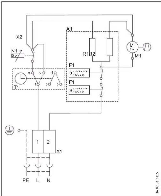
18.4 Wiring diagram CKZ 20 S 22
18.5 Wiring diagram CKR 20 S 23
18.6 Wiring diagram CKT 20 S 23
GUARANTEE | ENVIRONMENT AND RECYCLING
SPECIAL INFORMATION
- Keep children under the age of 3 away from the appliance if constant supervision cannot be guaranteed.
- Children from the age of 3 to 7 may switch the appliance on and off, provided they are supervised or have been instructed in the safe operation of the appliance and understand any risks that may result therefrom. This is subject to the appliance having been installed as described. Children from the age of 3 to 7 must not plug the power cable into its socket nor regulate the appliance.
- The appliance may be used by children aged 8 and up and persons with reduced physical, sensory or mental capabilities or a lack of experience and know-how, provided that they are supervised or they have been instructed on how to use the appliance safely and have understood the resulting risks.
- Children must never play with the appliance. Children must never clean the appliance or perform user maintenance unless they are supervised.
- The appliance could continue to heat the room unchecked if it is operated on a time switch. Ensure constant supervision if the appliance is used in a small room and the persons within that room cannot leave the room on their own.
- Parts of the appliance can get very hot and result in burns.
Particular caution is advised when children or persons in need of protection are present.
- Never cover the appliance.
- Never install the appliance directly below a wall socket.
- Install the appliance in such a way that the control equipment cannot be touched by a person in the bath or shower.
- In the case of a permanent connection, the appliance must be able to be separated from the power supply by an isolator that disconnects all poles with at least 3 mm contact separation.
- The power cable must only be replaced (for example if damaged) with the original spare part by a qualified electrician authorised by the manufacturer.
- Secure the appliance as described in chapter "Installation / Installation".
OPERATION
1. General information

Note
Read these instructions carefully before using the appliance and retain them for future reference.
Pass on the instructions to a new user if required.
1.1 Safety information
1.1.1 Structure of safety information

KEYWORD Type of risk Here, possible consequences are listed that may result from non-observation of the safety information.
▶ Steps to prevent the risk are listed.
1.1.2 Symbols, type of risk
| Symbol | Type of risk |
 | Injury |
 | Electrocution |
 | Burns or scalding |
 | Fire |
1.1.3 Keywords
| KEYWORD | Description |
| DANGER | If this information is not observed, it will result in serious injury or death. |
| WARNING | If this information is not observed, it can result in serious injury or death. |
| CAUTION | If this information is not observed, it can lead to medium or minor injury. |
1.2 Other symbols in this documentation

Note
Notes are bordered by horizontal lines above and below the text. General information is identified by the symbol shown on the left.
▶ Read these notes carefully.
Symbol

Damage to the appliance and environment

Appliance disposal

Never cover the appliance
This symbol indicates that you have to do something. The action you need to take is described step by step.
1.3 Units of measurement

Note
All measurements are given in mm unless stated otherwise.
2. Safety
Observe the following safety information and regulations.
Operate the appliance only when fully installed and with all safety equipment fitted.
2.1 Intended use
This appliance is designed to heat living areas.
Any other use beyond that described shall be deemed inappropriate. Observation of these instructions and of instructions for any accessories used is also part of the correct use of this appliance.
The appliance is intended for domestic use, i.e. it can be used safely by untrained persons. The appliance can also be used in a non-domestic environment, e.g. in a small business, as long as it is used in the same way.
2.2 General safety information

DANGER Fire
Never operate this appliance ...
- if the minimum clearances to adjacent object surfaces are not maintained, for example to furniture, net curtains, curtains, textiles or other flammable materials (for minimum clearances, see "Installation / Preparations").
- in rooms where the appliance is at risk from fire or explosion as a result of chemicals, dust, gases or vapours.
- in the direct proximity of pipes or receptacles that carry or contain flammable or explosive materials.
- if work such as laying cables, grinding or sealing is carried out in the installation room.
- if sprays, floor polish or similar products containing naphtha are used. Vent the room sufficiently before heating.
- if an appliance component is damaged, the appliance has fallen over or already has a fault.
- outdoors.

DANGER Fire
Never place any flammable, combustible or insulating objects or materials, such as laundry, blankets, magazines, containers with floor polish or naphtha, spray cans or similar on the appliance or in direct proximity to it.

WARNING Fire
Ensure that no foreign bodies enter the ventilation and extract air apertures. This could result in electric shock or fire or in damage to the appliance.

WARNING Fire
To prevent fires ensure that the air inlets and outlets are never blocked. Never position the appliance on soft surfaces, such as a bed, as this could result in the apertures becoming blocked.

DANGER Overheating
The appliance could continue to heat the room unchecked if it is operated on a time switch. Ensure constant supervision if the appliance is used in a small room and the persons within that room cannot leave the room on their own.

WARNING Injury
Keep children under the age of 3 away from the appliance if constant supervision cannot be guaranteed.
Children from the age of 3 to 7 may switch the appliance on and off, provided they are supervised or have been instructed in the safe operation of the appliance and understand any risks that may result therefrom. This is subject to the appliance having been installed as described. Children from the age of 3 to 7 must not plug the power cable into its socket nor regulate the appliance.
The appliance may be used by children aged 8 and up and persons with reduced physical, sensory or mental capabilities or a lack of experience and know-how, provided that they are supervised or they have been instructed on how to use the appliance safely and have understood the resulting risks.
Children must never play with the appliance. Children must never clean the appliance or perform user maintenance unless they are supervised.

CAUTION Burns
Parts of the appliance can get very hot and result in burns. Particular caution is advised when children or persons in need of protection are present.
2.3 General information

Damage to the appliance and environment
- Never cover this appliance.
- Never step on the appliance.
2.4 CE designation
The CE designation shows that the appliance meets all essential requirements according to the:
- Electromagnetic Compatibility Directive
- Low Voltage Directive
2.5 Test symbols
See type plate on the appliance.
3. Appliance description
This appliance is wall mounted and is particularly suitable for work rooms, kitchens, bathrooms, wash rooms and similar.
The external casing of the appliance is made from stove enamelled sheet steel. The sides are made from plastic. The controls are located on the r.h. side panel.
The quiet fan draws in the ambient air that is heated by a bare wire heater element. The air then exits evenly through the hot air channel and the air outlet grille set into the bottom of the appliance.
The appliance heats up the ambient air inside the room and maintains it at the selected temperature.
After mounting the appliance on the wall and making the electrical connection using a mains plug, the appliance is ready for operation.
4. Operation CK 20 S
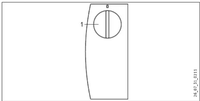
1 Temperature selector
4.1 Starting heating
The temperature is infinitely adjustable. The appliance switches off as soon as the selected room temperature has been reached.
▶ Turn the temperature selector clockwise to the required setting.
4.2 Control with external room temperature controller
In rooms larger than 20 m ^2 you can operate the appliance with a conventional external room temperature controller.
▶ To do so, turn the temperature selector fully clockwise.
4.3 Stopping heating / Frost protection
▶ Turn the temperature selector fully anti-clockwise.
This position ensures frost protection. The heater starts automatically if the room temperature drops below the frost protection temperature.
4.4 Taking the appliance out of use
▶ Pull the plug from the power socket.
5. Operation CKZ 20 S
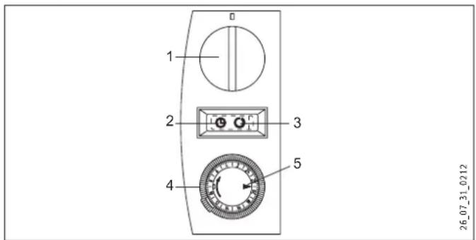
1 Temperature selector
2 Rocker switch position (Operation with the time switch)
3 Rocker switch position (Standard operation)
4 Time switch
5 Marker arrow
5.1 Starting heating
▶ Use the rocker switch to select one of the following operating6.1 Starting heating
modes:
- Standard operation
- Operation with the time switch
Standard operation
The temperature is infinitely adjustable. The appliance switches off as soon as the selected room temperature has been reached.
▶ Turn the temperature selector clockwise to the required setting.
Operation with the time switch
The 24-hour time switch has 96 time segments. Every hour is divided into 4 time segments of 15 minutes. The time switch has to be reset when commissioning the appliance and after any power interruption. To do this, turn the time switch clockwise until the marker arrow points to the current time.
To select the required heating time, proceed as follows:
Press down the time segments around the circumference. Red markings will become visible, indicating the preselected heating time at which the appliance automatically starts to heat. If the required room temperature has been reached during the heat-up time, the appliance switches off. It starts again if there is a further heat demand and will continue doing so until the selected heating time has elapsed. This process is repeated daily. The heating time can be adjusted at any time if required by pressing time segments up or down.
5.2 Stopping heating / Frost protection
▶ Turn the temperature selector fully anti-clockwise.
In this setting, frost protection is only ensured if the rocker switch is positioned for "Standard operation". The heater starts automatically if the room temperature drops below the frost protection temperature.
5.3 Taking the appliance out of use
▶ Pull the plug from the power socket.
6. Operation CKR 20 S
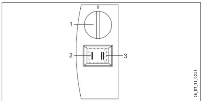
1 Temperature selector
2 Rocker switch stage (Base heating stage)
3 Rocker switch stage (Quick heating stage)
▶ Turn the temperature selector clockwise to the required setting.
The temperature is infinitely adjustable. The appliance switches off as soon as the selected room temperature has been reached.
You can use the rocker switch to choose between the following two outputs with matched fan motor speed:
Base heating stage
Set the rocker switch to "I". Provided that the appliance has been switched on via the temperature selector, it will heat with an output of 1000 W at the slow fan stage.

Note
Never operate the appliance at standard heating stage I, if the room where the appliance has been installed has cooled down severely.
▶ If the room has cooled down severely, switch the appliance to rapid heating stage II in order to ensure normal appliance operation.
Quick heating stage
Set the rocker switch to "II". Provided that the appliance has been switched on via the temperature selector, it will heat with an output of 2000 W at the quick fan stage.
Select the powerful quick heating stage if you need to heat up a cold room rapidly to the selected temperature. Afterwards, set the rocker switch back to stage "I".
Once the preselected room temperature has been reached, the appliance switches off. The appliance then starts and stops heating as necessary to keep the room temperature constant.
6.2 Control with external room temperature controller
In rooms larger than 20 m² you can operate the appliance with a conventional external room temperature controller.
▶ To do so, turn the temperature selector fully clockwise.
6.3 Stopping heating / Frost protection
▶ Turn the temperature selector fully anti-clockwise and select quick heating stage "II" on the rocker switch.
This position ensures frost protection. The heater starts automatically if the room temperature drops below the frost protection temperature.
6.4 Taking the appliance out of use
▶ Pull the plug from the power socket.
7. Operation CKT 20 S
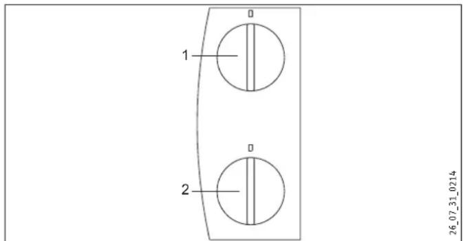
1 Temperature selector
2 Time switch
7.1 Starting heating
The temperature is infinitely adjustable. The appliance switches off as soon as the selected room temperature has been reached.
▶ Turn the temperature selector clockwise to the required setting.
7.2 Adjusting the time switch
With the time switch, the appliance heats with full output and without temperature control.
▶ Turn the time switch selector clockwise to set any number of minutes to count down, from 0 - 60 minutes.
7.3 Stopping heating / Frost protection
▶ Turn the temperature selector fully anti-clockwise and ensure that the time switch is set to "0".
This position ensures frost protection. The heater starts automatically if the room temperature drops below the frost protection temperature.
7.4 Taking the appliance out of use
▶ Pull the plug from the power socket.
8. Cleaning, care and maintenance
The appliance contains no user serviceable parts.
Clean the appliance when cold with ordinary cleaning products. Avoid abrasive or corrosive cleaning products.
If a pale brownish discolouration appears on the appliance casing, wipe this off as soon as possible with a damp cloth.
! Damage to the appliance and environment Never spray cleaning spray into the air slot.
9. Storage
▶ When not in use, keep the appliance in a dry place.
10. Troubleshooting
If the appliance does not heat, check the temperature set at the appliance and the MCB/fuse in your fuse box.
The appliance has a temperature limiter that shuts the appliance down if it overheats. After the cause has been removed (for example air outlet or inlet apertures covered) and the appliance has cooled down for a few minutes, operation starts again.
If you cannot remedy the fault, notify your heating contractor. To facilitate and speed up your enquiry, please provide the serial number from the type plate (000000-0000-000000).
INSTALLATION
11. Safety
Only qualified contractors should carry out the maintenance and repair of this appliance.
11.1 General safety information
We guarantee trouble-free operation and operational reliability only if the original accessories and spare parts intended for the appliance are used.
11.2 Instructions, standards and regulations

Note
Observe all applicable national and regional regulations and instructions.
12. Appliance description
This appliance is a wall mounted electric direct heater. This appliance is particularly suitable for heating rooms, such as work rooms, kitchens, bathrooms, wash rooms etc.
12.1 Standard delivery
- Wall mounting bracket
- Fixing bracket
13. Preparations
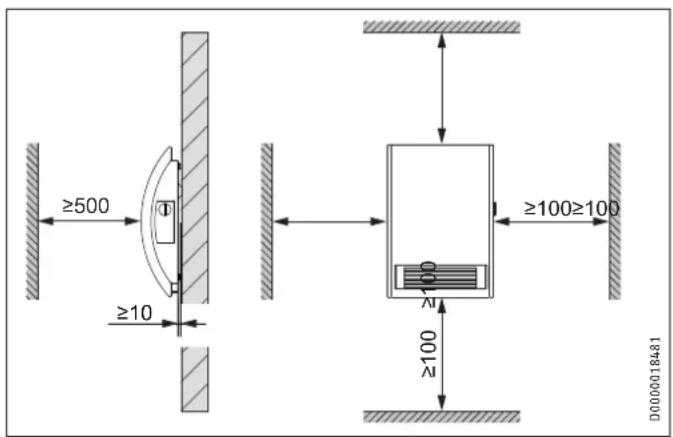
13.1 Minimum clearances
14. Assembly

DANGER Electrocution
- If installing the appliance in rooms with a bath and/or shower, take the relevant safety zone into account in accordance with the information on the appliance type plate.
- Install the appliance in such a way that switching and control equipment cannot be touched by a person in the bath or shower.

DANGER Fire
- Only fit the appliance to a vertical wall that is temperature-resistant to at least 90 °C.
- Maintain minimum clearances to adjacent surfaces.
- Never install the appliance directly below a wall socket.
▶ Check the hole distances for the wall mounting bracket in the dimensioned drawing.
- Secure the wall mounting bracket with suitable fixing materials. The horizontal and vertical slots in the wall mounting bracket enable alignment if drilled holes are not completely accurate.
▶ Hook in the appliance so that both top protrusions in the back panel are inserted into the slots in the wall mounting bracket.
▶ Secure the appliance with the fixing bracket and one screw against unintentional unhooking. Hook the fixing bracket from behind into the back panel.
15. Electrical connection

DANGER Electrocution
Carry out all electrical connection and installation work in accordance with relevant regulations.

Damage to the appliance and environment
- Observe the type plate. The specified voltage must match the mains voltage.
The cable must not touch the appliance.
Ensure the socket or junction box is at least 10 cm from the appliance.
Never install the appliance directly below a wall socket.
If a permanent connection is required, trim the cable (cut off the plug) so that it is routed directly to the junction box.
In the case of a permanent connection, the appliance must be able to be separated from the power supply by an isolator that disconnects all poles with at least 3 mm contact separation.
This appliance is unsuitable for fixed cables.
16. Appliance handover
Explain the functions of the appliance to users. Draw their attention in particular to the safety information. Hand over the operating and installation instructions to users.
17. Troubleshooting
The power cable must only be replaced by a qualified contractor using original spare parts supplied by us.
18. Specification
18.1 Dimensioned connection drawing
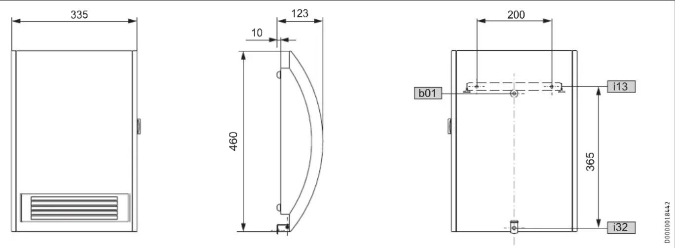
D0000018442
b01 Entry electrical cables
i13 Wall mounting bracket
i32Fixing
18.2 Data table
| CK 20 S | CKZ 20 S | CKR 20 S | CKT 20 S | ||
| Part number | 071793 | 071795 | 072633 | 230344 | |
| Electrical details | |||||
| Connection output | W | 2000 | 2000 | 2000 | 2000 |
| Phases | 1/N/PE | 1/N/PE | 1/N/PE | 1/N/PE | |
| Rated voltage | V | 230 | 230 | 230 | 230 |
| Frequency | Hz | 50 | 50 | 50 | 50 |
| Dimensions | |||||
| Height | mm | 460 | 460 | 460 | 460 |
| Width | mm | 335 | 335 | 335 | 335 |
| Depth | mm | 123 | 123 | 123 | 123 |
| Weights | |||||
| Weight | kg | 4,4 | 4,4 | 4,4 | 4,4 |
| Versions | |||||
| Version | 24 h time switch | 60-minute short-time timer | |||
| Frost protection setting | °C | 7 | 7 | 7 | 7 |
| IP-Rating | IP13B | IP13B | IP13B | IP13B | |
| Protection class | I | I | I | I | |
| Colour | alpine white | alpine white | alpine white | alpine white | |
| Values | |||||
| Output stages | kW | 1,0 / 2,0 | |||
| Setting range | °C | 5-30 | 5-30 | 5-30 | 5-30 |
| Operating noise | dB(A) | 53 | 53 | 42/51 | 53 |
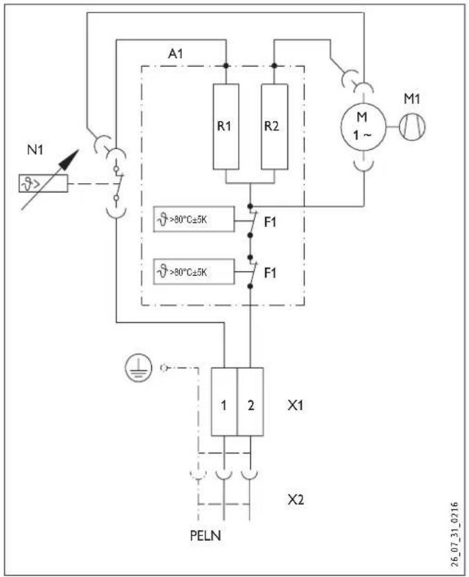
18.3 Wiring diagram CK 20 S
flowchart
graph TD
    A["N1"] --> B["Switch"]
    B --> C["R1"]
    C --> D["R2"]
    D --> E["M 1~"]
    E --> F["M1"]
    G[">80°C±5K"] --> H["F1"]
    I[">80°C±5K"] --> J["F1"]
    H --> K["X1"]
    J --> L["X1"]
    K --> M["PELN"]
    L --> N["X2"]
    M --> O["Ground"]
    N --> P["Ground"]
    style A fill:#f9f,stroke:#333
    style B fill:#ccf,stroke:#333
    style C fill:#cfc,stroke:#333
    style D fill:#cfc,stroke:#333
    style E fill:#fcc,stroke:#333
    style F fill:#fcc,stroke:#333
    style G fill:#fff,stroke:#333
    style H fill:#fff,stroke:#333
    style I fill:#fff,stroke:#333
    style J fill:#fff,stroke:#333
    style K fill:#fff,stroke:#333
    style L fill:#fff,stroke:#333
    style M fill:#fff,stroke:#333
    style N fill:#fff,stroke:#333
    style O fill:#fff,stroke:#333
A1 Electric heater element assembly
F1 Overheating protection
M1 Fan
N1 Temperature controller
R1 Heating resistor
R2 Heating resistor
X1 Socket terminal
X2 Plug-in connection
18.4 Wiring diagram CKZ 20 S
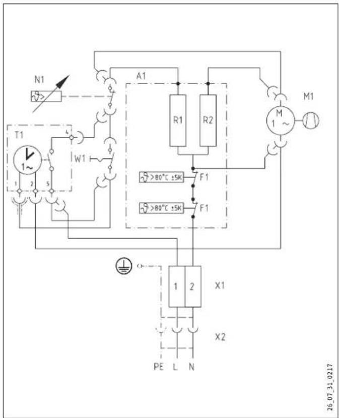
A1 Electric heater element assembly
F1 Overheating protection
M1 Fan
N1 Temperature controller
R1 Heating resistor
R2 Heating resistor
T1 Time switch
W1 Rocker switch
X1 Socket terminal
X2 Plug-in connection
18.5 Wiring diagram CKR 20 S
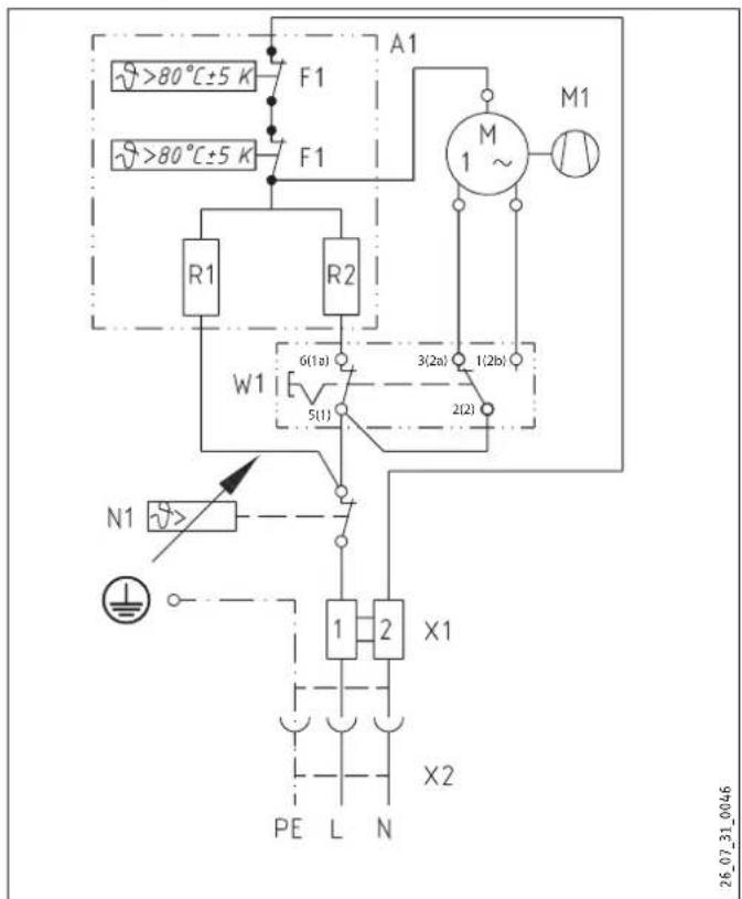
A1 Electric heater element assembly
F1 Overheating protection
M1 Fan
N1 Temperature controller
R1 Heating resistor
R2 Heating resistor
W1 Rocker switch
X1 Socket terminal
X2 Plug-in connection
18.6 Wiring diagram CKT 20 S
A1 Electric heater element assembly
F1 Overheating protection
M1 Fan
N1 Temperature controller
R1 Heating resistor
R2 Heating resistor
T1 60 minute time switch
X1 Socket terminal strip
Warranty
For warranty conditions please see following pages.
Environment and recycling
We would ask you to help protect the environment. After use, dispose of the various materials in accordance with national regulations.
Stiebel Eltron Warranty for Hand Dryers & Space Heaters - Models HTE, ULTRONIC, CNS, CK & CK Z.
Who gives the warranty
- The warranty is given by Stiebel Eltron (Aust) Pty Ltd (A.B.N. 82 066 271 083) of 6 Prohasky Street, Port Melbourne, Victoria, 3207 ("we", "us" or "our").
The warranty
- This warranty applies to Stiebel Eltron Hand Dryers and Space Heaters – Models HTE 4, HTE 5, ULTRONIC, CNS 100, CNS 150, CNS 200, CNS 250, CK 20S and CKZ 20S (the "unit") manufactured after 1 May 2015.
- Subject to the warranty exclusions we will repair or replace, at our absolute discretion, a faulty component in your unit free of charge if it fails to operate in accordance with its specifications during the warranty period.
- If we repair or replace a faulty component to your unit under this warranty, the warranty period is not extended from the time of the repair or replacement.
- The warranty period commences on the date of purchase of the unit. Where the date of purchase is not known, then the warranty period will commence 2 months after the date of manufacture.
- The warranty period for a unit is shown in the table below.
| Component Warranty period | |
| All components 5 years from | the date of purchase of the unit. |
Your entitlement to make a warranty claim
- You are entitled to make a warranty claim if:
7.1. you own the unit or if you have the owner's consent to represent the owner of the unit;
7.2. you contact us within a reasonable time of discovering the problem with the unit;
How you make a warranty claim
- To make a warranty claim you must provide us with the following information:
8.1. The model number of the unit;
8.2. A description of the problem with the unit;
8.3. The name, address and contact details (such as phone number and e-mail address) of the owner;
8.4. The address where the unit is installed and the location (e.g. in living room);
8.5. The serial number of the unit;
8.6. The date of purchase of the unit and the name of the seller of the unit;
8.7. The date of installation of the unit where appropriate;
8.8. A copy of the certificate of compliance when the unit was installed where appropriate.
9. The contact details for you to make your warranty claim are:
Name: Stiebel Eltron (Aust) Pty Ltd
Address: 6 Prohasky Street, Port Melbourne, Victoria, 3207
Telephone: 1800 153 351
(8.00 am to 5.00 pm AEST Monday to Friday)
Contact person: Customer Service Representative
E-mail: service@stiebel.com.au
- We will arrange a suitable time with you to inspect and test the unit.
Warranty exclusions
- We may reject your warranty claim if:
11.1. The unit was not installed by registered and qualified tradespeople, where required.
11.2. The unit was not installed and commissioned:
(a) in Australia;
(b) in accordance with the Operating and Installation Guide; and
(c) in accordance with the relevant statutory and local requirements of the State or Territory in which the unit is installed.
11.3. The unit has not been operated or maintained in accordance with the Operating and Installation Guide.
11.4. The unit does not bear its original Serial Number or Rating Label.
11.5. The unit was damaged by any or any combination of the following:
(a) normal fair wear and tear;
(b) connection to an incorrect power supply;
(c) connection to faulty equipment, such as faulty circuit breaker;
(d) accidental damage;
(e) act of God, including damage by flood, storm, fire, lightning strike and the like;
(f) wiring not to AS3000 Standards
11.6. The unit was damaged before it was installed e.g. it was damaged in transit.
11.7. An unauthorised person has modified, serviced, repaired or attempted to repair the unit without our consent.
11.8. Non genuine parts other than those manufactured or approved by us have been used on the unit.
12. We may charge you:
12.1. for any additional transport costs if the unit is installed more than 30 kilometres from our closest authorised service technician.
12.2. for the extra time it takes our authorised service technician to access the unit for inspection and testing if it is not sited in accordance with the Operating and Installation Guide and not readily accessible for inspection.
12.3. for any extra costs of our authorised service technician to make the unit safe for inspection.
13. You must ensure that access to the unit by our authorised service technician is safe and free from obstruction.
14. Our authorised service technician may refuse to inspect and test the unit until you provide safe and free access to it, at your cost.
15. If we reject your warranty claim in accordance with clause 11, we may charge you for our authorised service technician's labour costs to inspect and test the unit.
16. In order to properly test the unit we may remove it to another location for testing.
Australian Consumer Law
- Our goods come with guarantees that cannot be excluded under the Australian Consumer Law. You are entitled to a replacement or refund for a major failure and compensation for any other reasonably foreseeable loss or damage. You are also entitled to have the goods repaired or replaced if the goods fail to be of acceptable quality and the failure does not amount to a major failure.
- The Stiebel Eltron warranty for the unit is in addition to any rights and remedies you may have under the Australian Consumer Law.
Deutschland
Rm 102, F1, Yingbin-Yihao Mansion, No. 1
Yingbin Road
Panyu District | 511431 Guangzhou
Tel. 020 39162209 | Fax 020 39162203
info@stiebeleltron.cn
www.stiebeleltron.cn
Czech Republic
STIEBEL ELTRON spol. s r.o.
Urzhumskaya street 4,
building 2 | 129343 Moscow
Tel. 0495 7753889 | Fax 0495 7753887
info@stiebel-eltron.ru
www.stiebel-eltron.ru
Slovakia
TATRAMAT - ohrievače vody s.r.o.
Hlavná 1 | 058 01 Poprad
Tel. 052 7127-125 | Fax 052 7127-148
info@stiebel-eltron.sk
www.stiebel-eltron.sk
Switzerland
STIEBEL ELTRON AG
Industrie West
Gass 8 | 5242 Lupfig
Tel. 056 4640-500 | Fax 056 4640-501
info@stiebel-eltron.ch
www.stiebel-eltron.ch
Thailand
STIEBEL ELTRON Asia Ltd.
469 Moo 2 Tambol Klong-Jik
Amphur Bangpa-In | 13160 Ayutthaya
Tel. 035 220088 | Fax 035 221188
info@stiebeleltronasia.com
www.stiebeleltronasia.com
United Kingdom and Ireland
STIEBEL ELTRON UK Ltd.
Unit 12 Stadium Court
Stadium Road | CH62 3RP Bromborough
Tel. 0151 346-2300 | Fax 0151 334-2913
info@stiebel-eltron.co.uk
www.stiebel-eltron.co.uk
United States of America
STIEBEL ELTRON, Inc.
17 West Street | 01088 West Hatfield MA
Tel. 0413 247-3380 | Fax 0413 247-3369
info@stiebel-eltron-usa.com
www.stiebel-eltron-usa.com

Irrtum und technische Änderungen vorbehalten! | Subject to errors and technical changes! | Sous réserve d'erreurs et de modifications techniques! | Onder voorbehoud van vergissingen en technische wijzigingen! | Salvo error o modificación técnica! | Excepto erro ou alteração técnica | Zastrzežone zmiany techniczne i ewentualne błędy | Omyly a technické změny jsou vyhrazeny! | A muszaki változtatások és tévedések jo gát fenntartjuk! | Отсутствие ошибок не гарантируется. Возможны технические изменения. | Chyby a technické zmeny sú vyhradené! Stand 8969
STIEBEL ELTRON