Armour VA8004 - Computer Case THERMALTAKE - Free user manual and instructions
Find the device manual for free Armour VA8004 THERMALTAKE in PDF.


| Product Type | Super Tower Computer Case |
| Model | Armour VA8004 (Extreme Edition) |
| Dimensions (H x W x D) | 585 x 210 x 558 mm (23.0 x 8.3 x 22.0 in) |
| Weight | Approx. 14.5 kg (32.0 lbs) |
| Motherboard Compatibility | Extended ATX, Standard ATX, Micro ATX |
| Drive Bays - 5.25" | Up to 5 (tool-free clips) |
| Drive Bays - 3.5" | Up to 6 (including removable HDD cages and 12 cm fan cage) |
| Cooling - Front | 2 x 120 mm fans (included) or optional 140 mm |
| Cooling - Rear | 1 x 90 mm fan (included) |
| Cooling - Top | Supports 120 mm fan (optional, tool-free mounting) |
| CPU Cooler Height Limit | Up to 100 mm (with air guide); up to 200 mm without guide |
| Power Supply Compatibility | Standard ATX PSU (not included); equipped with detachable PSU supporter |
| Expansion Slots | 7 I/O slots (tool-free PCI bracket design) |
| Front Panel Ports | 2 x USB 2.0, 1 x IEEE 1394 FireWire, audio (AC'97 / HD Audio) |
| Special Features | Dual channel air guide for AMD Quad FX, removable 12 cm fan cage, tool-free drive installation, side panel lock and key, case open alarm (intrusion switch) |
| Material | Steel chassis with perforated panels |
| Included Accessories | Screw kit, side panel key, user manual |
| Compliance | FCC, CE |
Frequently Asked Questions - Armour VA8004 THERMALTAKE
User questions about Armour VA8004 THERMALTAKE
0 question about this device. Answer the ones you know or ask your own.
Ask a new question about this device
Download the instructions for your Computer Case in PDF format for free! Find your manual Armour VA8004 - THERMALTAKE and take your electronic device back in hand. On this page are published all the documents necessary for the use of your device. Armour VA8004 by THERMALTAKE.
USER MANUAL Armour VA8004 THERMALTAKE
Thermaltake Coolall YOUR LIFE

Extreme Edition VA8004 Series
User's Manual
natural_image
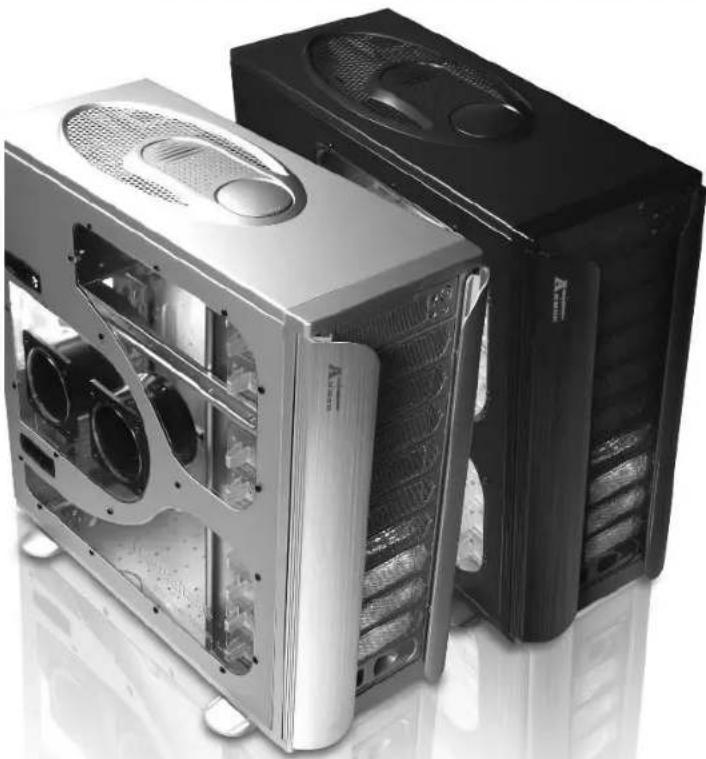
Exterior view of two computer tower units with ventilation grilles and ventilation fans (no text or symbols visible)©2006 Thermaltake Technology Co., Ltd. All Rights Reserved. 2006.11 All other registered trademarks belong to their respective companies.www.thermaltake.com
FC Tried to Comply With FCC Standards FOR HOME OR OFFICE USE
CE

Thermaltake COOLALL YOUR LIFE
AMD Quad FX
Platform Ready Super Tower Chassis
Contents
Chapter1 Product Introduction
1.1 Notice 1
Chapter2 Case Mechanical Operation
2.1 How to open the side panel 3
2.2 Installing 5.25" Device 4
2.3 Installing 3.5" HDD 5
2.4 Removable 12cm Fan cage with 3HDD 6
2.5 Installing 3.5" HDD For 12cm Fan Cage 7
2.6 5.25" to 3.5" Drive Tray Device Installation 8
2.7 Installing 3.5" Device to Drive Tray 10
With Power Button
2.8 Installing Power Supply 12
2.9 Installing the Fan on Top of the Case 13
2.10 How to Remove the Fan & Fan Holder 14
2.11 PCI slot tool-free function operation 15
Chapter3 Motherboard & Leads Installation
3.1 Motherboard Installation 16
3.2 Case LED connections 17
3.3 USB2.0 & IEEE1394 Firewire connection 18
3.4 Audio Connection 20
3.5 Case open alarm function (Intrusion switch) 20
Chapter1 Product Introduction
1.1 Notice
- The side panel with dual channel air guide is designed specifically for AMD Quad FX platform
- If you do not intend to use AMD's designated cooler, please follow the directions listed below:
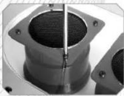
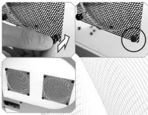
a. If the cooler you are planning to use is taller than 100 mm, please remove the air guides and follow directions to cover the air hole with included perforated panel.
natural_image
Close-up of a mechanical component with a central pin and flange (no visible text or symbols)To remove the fan duct, please unscrew the 4 screws on side panel.

natural_image
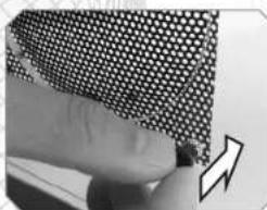
Close-up of a finger pressing down on a textured surface with a black arrow symbol (no text or symbols present)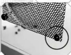
natural_image
Close-up of a grid-patterned surface with two black dots and a circled area, no visible text or symbolsPlace the metal mesh over the side panel opening. First, insert the female rivet(A) into the screw hole. Then, insert the male push-pin(B) to secure. Repeat steps for all other screw holes.

Note: Does not apply to non-window version side panel.
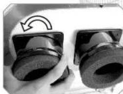
b. If the cooler you are planning to use is within the 64 mm and 100 mm range, you may adjust the air guides so that it may cover directly over the cooler.
natural_image
Close-up of two mechanical components with a curved arrow indicating rotation (no text or symbols visible)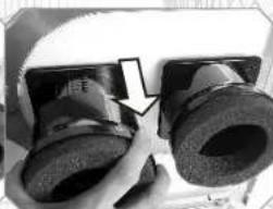
natural_image
Close-up of a VR headset with two lenses and a hand adjusting the lens (no visible text or symbols)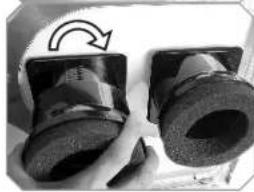
natural_image
Close-up of two mechanical components with a curved arrow indicating rotation (no visible text or symbols)To adjust the depth of the air guide, please twist the air guide counter-clockwise to unlock. To lock the air guide in place, please twist the air guide clockwise.
Armor Extreme Edition supports all Intel or AMD systems
Chapter2 Case Mechanical Operation
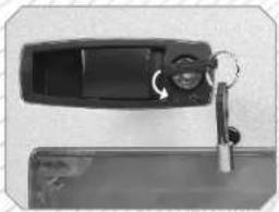
2.1 How to open the side panel
natural_image
Close-up of a black plastic door with a key inserted, showing a curved arrow and lock mechanism (no text or symbols visible)To find out the side panel key from the back side of the case then open it as the picture.
natural_image
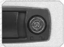
Close-up of a black electronic device handle with a circular button and indicator lights (no visible text or symbols)Make sure the side panel lock is opened.
natural_image
Top-down view of a computer motherboard showing CPU socket, ventilation ducts, and drive bays (no text or symbols visible)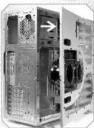
natural_image
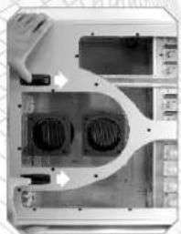
Interior view of a computer tower case showing internal components and ventilation ducts (no visible text or labels)Push the button then swing out the side panel.

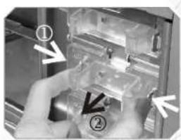
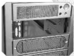
2.2 Installing 5.25" Device
natural_image
Close-up of hands installing or adjusting a mechanical component with numbered callouts (no visible text or symbols)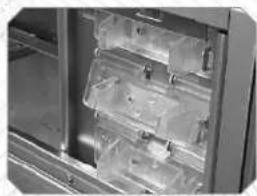
natural_image
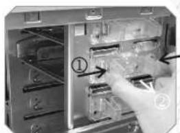
Close-up of a refrigerator interior showing plastic storage compartments (no visible text or labels)Squeeze and pull out-ward the tool-free clip

natural_image
Close-up of a desktop computer tower with ventilation grilles and drive bays (no visible text or labels)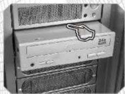
natural_image
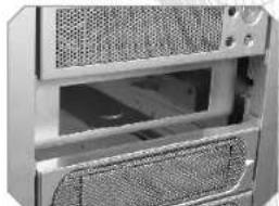
Close-up of a desktop computer tower with drive bays and ventilation grilles (no visible text or labels)Remove the drive bay cover from the selected position, then insert the device into the 5.25" drive bay

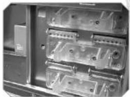
natural_image
Interior view of an electronic device showing internal components (no visible text or symbols)Squeeze and push in-ward the tool-free clip.

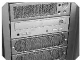
natural_image
Front view of a desktop computer tower with ventilation grilles and drive bays (no visible text or labels)Finish installation

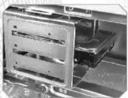
2.3 Installing 3.5" HDD
Unscrew the thumb screw for removable HDD cage
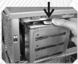
natural_image
Close-up of a hand inserting a card into a computer tower (no visible text or symbols)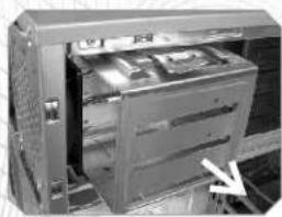
natural_image
Interior view of a computer tower case showing internal components and a white arrow pointing to a component (no visible text or symbols)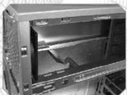
natural_image
Interior view of a server rack unit with visible internal components (no text or labels)Push down and hold the metal tab, then pull the HDD cage out-ward to remove from chassis.
natural_image
Close-up of an open electronic device showing internal components and casing (no visible text or symbols)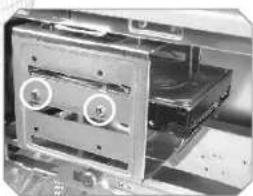
natural_image
Close-up of an open electronic device showing internal components and a circular annotation (no visible text or symbols)Secure HDD with Screw
2.4 Removable 12cm Fan cage with 3HDD
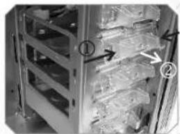
natural_image
Interior view of a storage rack with numbered arrows indicating components (no readable text or symbols)Squeeze and pull out-ward the tool-free clip
Note: Remove 12 cm fan cage is secured with 3 tool-free clips. Be sure to free all 3 tool-free clips
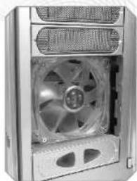
natural_image
Close-up of a computer tower fan with visible internal blades and ventilation slots (no text or symbols)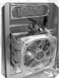
natural_image
Interior view of a computer tower case showing internal fan and ventilation slots (no visible text or labels)After loosen tool-free clip, remove 3 drive bay covers located in front of the 12cm fan cage. Then slide the fan cage out-ward to remove.
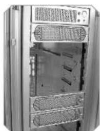
natural_image
Exterior view of a server rack unit with ventilation grilles and internal components (no visible text or symbols)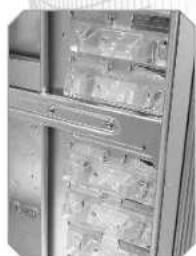
natural_image
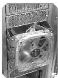
Close-up of a refrigerator with visible shelves and doors (no text or symbols)Remove another 3 drive bay covers at desired location for 12 cm fan cage. Squeeze and pull out-ward the tool-free clip at desired location
natural_image
Close-up of a computer tower case with a transparent CPU socket and heatsink (no visible text or symbols)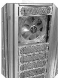
natural_image
Close-up of a metallic industrial fan or compressor unit with ventilation grilles (no visible text or symbols)Insert the 12 cm fan cage into the desired location by sliding the cage in-ward from the front of chassis.
natural_image
Close-up of a refrigerator with open doors and shelves (no visible text or labels)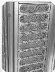
natural_image
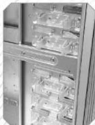
Close-up of a metallic cylindrical device with multiple recessed ventilation grilles (no text or symbols visible)Squeeze and push in-ward the tool free clip to secure the 12 cm fan cage.
Replace back the 3 drive bay covers previously removed
2.5 Installing 3.5" HDD (For 12cm Fan Cage)
natural_image
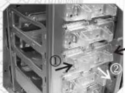
Interior view of a server rack with numbered storage compartments (no visible text or symbols)Squeeze and pull out-ward the tool-free clip at desired slot.
natural_image
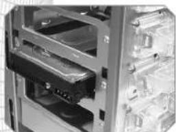
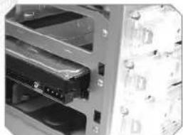
Interior view of a server rack with multiple drive bays (no visible text or labels)Insert HDD by sliding HDD into the 12 cm fan cage.
natural_image
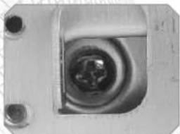
Close-up of a metallic mechanical component with a central circular feature and mounting holes (no visible text or symbols)Secure HDD by tightening screw to HDD
natural_image
Close-up of a mechanical or electronic device with multiple ports and connectors (no visible text or symbols)Squeeze and push in-ward the tool free clip to secure the HDD in the 12 cm fan cage.
2.6 5.25" to 3.5" Drive Tray Device Installation.
natural_image
Close-up of a computer interface showing a hand inserting a component into a drive (no visible text or symbols)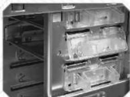
natural_image
Interior view of a refrigerator with visible door, shelves, and legs (no text or symbols)Squeeze and pull out-ward the tool-free clip securing the drive tray
natural_image
Close-up of a computer tower with ventilation grilles and ventilation grilles (no visible text or symbols)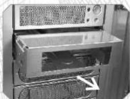
natural_image
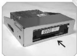
Interior view of a microwave oven with visible dish, fan, and rack (no text or symbols)Remove drive bay cover in front of the drive tray. Then slide out the device tray.
natural_image
Exterior view of a CD-ROM drive with an arrow pointing to its front panel (no visible text or symbols)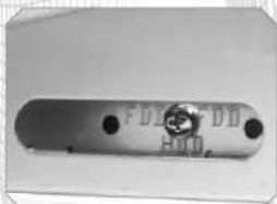
natural_image
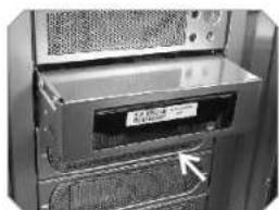
Metallic electronic component with two terminals and a circular feature, no visible text or symbolsInsert HDD drive into device tray. Secure HDD with screw from the side of device tray labeled HDD.
natural_image
Interior view of a computer tower showing drive bays and a labeled card (no readable text or symbols)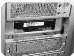
natural_image
Close-up of a computer tower case showing ventilation grilles and drive bays (no visible text or symbols)Insert back the device tray and replace back the drive bay cover.
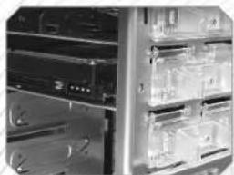
natural_image
Interior view of a server rack with multiple drive bays and ventilation grilles (no visible text or labels)Squeeze and push in-ward the tool free clip to secure the device tray.
Installing Floppy Disk Drive to Device tray
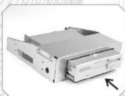
natural_image
Exterior view of a silver internal optical drive (no visible text or labels)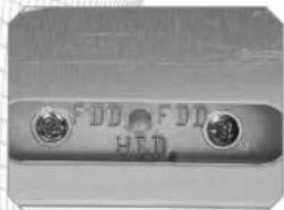
natural_image
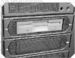
Close-up of a metallic connector with two circular buttons and a small logo (no readable text or symbols)Remove device tray and insert floppy disk drive into device tray. Secure FDD with screw from the side of device tray labeled FDD.
natural_image
Close-up of server rack-mounted drive bays with ventilation grilles and drive slots (no visible text or labels)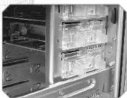
natural_image
Interior view of a refrigerator with visible door, shelves, and storage compartments (no text or symbols)Insert back device tray. Remove mesh on drive bay cover. Then replace back drive bay cover. Squeeze and push in-ward the tool free clip to secure the device tray
2.7 Installing 3.5" Device to Drive Tray With Power Button
natural_image
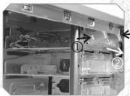
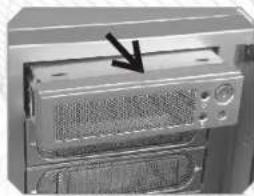
Close-up of a computer tower with ventilation grilles and a black arrow pointing to a component (no text or symbols visible)Squeeze and pull out-ward the tool-free clip securing the drive tray with power button. Remove and slide drive bay out-ward to remove.
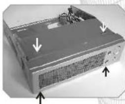
natural_image
Exterior view of a server rack with ventilation grilles and mounting points (no text or symbols visible)Squeeze both top and bottom portion of drive tray cover picture to the left to remove cover.
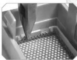
natural_image
Close-up of a metallic mechanical component with a perforated base and raised lever (no visible text or symbols)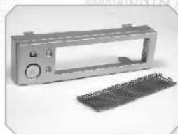
natural_image
Exterior view of a metallic electrical enclosure with a grid base (no text or symbols visible)Remove mesh from cover
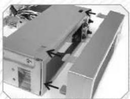
natural_image
Exterior view of a modern office building (no signage)Place cover back to drive tray to its original position. Insert 3.25" device and secure device with screw.
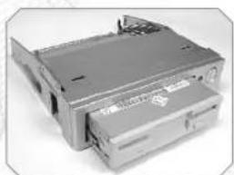
natural_image
Exterior view of a silver computer drive unit (no visible text or labels)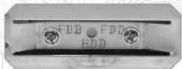
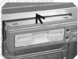
natural_image
Close-up of a computer monitor with an arrow pointing to the left side (no visible text or symbols)Insert back the device tray pictured above. Squeeze and push in-ward the tool free clip to secure the device tray
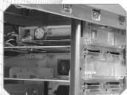
natural_image
Interior view of an industrial equipment cabinet with shelves and control panels (no visible text or labels)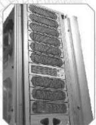
natural_image
Close-up of a server rack unit with multiple drive bays (no visible text or labels)Drive tray with Power Button can be placed at any drive bay desired.
2.8 Installing Power Supply
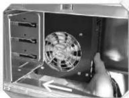
natural_image
Interior view of a computer tower with a fan and drive mechanism (no visible text or symbols)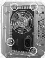
Install power supply unit as shown in pictures
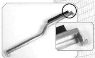
natural_image
Close-up of a metallic tool with a magnified inset showing detail (no text or symbols visible)
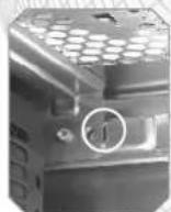
Locate the hook of PSU supporter on the hole which is circled in photo above
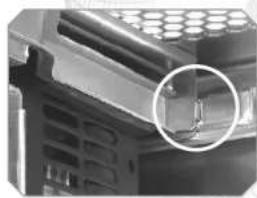
natural_image
Close-up of a mechanical component with a magnified inset showing a small circular detail (no visible text or symbols)Swing the supporter to its proper position as shown in photo above
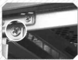
natural_image
Close-up of a mechanical component with a circular inset showing a close-up view of a device (no visible text or symbols)Secure the supporter with screw
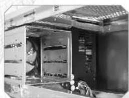
natural_image
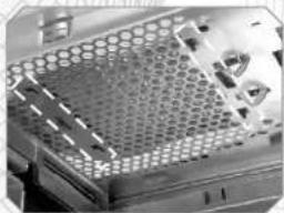
Interior view of an industrial machine with cooling fans and wiring (no visible text or symbols)2.9 Installing the fan on top of the case
natural_image
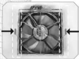
Close-up of a perforated metal tray with hexagonal patterns and internal structures (no visible text or symbols)Press-in 2 clips on the side of fan
natural_image
Close-up of a black-and-white photo of a mechanical fan or compressor unit with visible blades and mounting brackets (no text or symbols)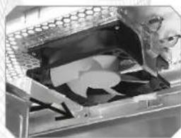
natural_image
Close-up of a mechanical component with internal components and a meshed structure (no visible text or symbols)Align all clips with mounting holes, then push-in the fan against case body to secure it.
natural_image
Close-up of a perforated metal panel with a hand pointing to a small object, no visible text or symbols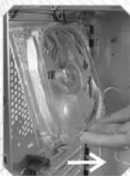
natural_image
Close-up of a hand holding a transparent plastic bag with a white arrow pointing to it (no visible text or symbols)Push fan clip upward to loose fan, then remove fan holder from inside
9 cm rear fan
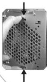
natural_image
Close-up of a perforated metal plate with arrows indicating direction (no text or symbols visible)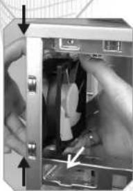
natural_image
Close-up of hands installing or adjusting a mechanical component inside a device (no visible text or symbols)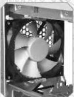
To remove fan & fan holder by press-in clips then pull both from inside. Please see above picture
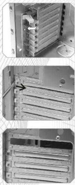
2.11 PCI slot tool-free function operation
Open the plastic clip then take off the PCI bracket as follow.
Chapter3 Motherboard & Leads Installation
3.1 Motherboard Installation
Each motherboard has different standoff layout. It is highly suggested that you refer to your motherboard's manual when installing motherboard into the case. The cases are applicable with Extend-ATX Standard ATX, Micro ATX motherboards. Your motherboard may require a special I/O Panel, which should be included with your motherboard.
Placement Direction:
When installing the motherboard, make sure you follow the direction provided by your motherboard manufacturer. On most standard motherboards, the edge with external ports goes to the rear part of the chassis. It is highly recommended that you install CPU, heat sink and modular components before fixing the motherboard inside the chassis.
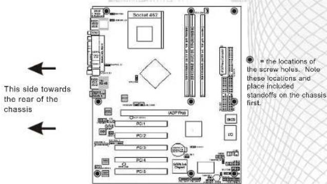
- = the locations of the screw holes. Note these locations and place included standoffs on the chassis first.
Above illustration is a sample of what the motherboard's layout. For more detail screw hole placement, please refer to your motherboard manual.
3.2 Case LED connections
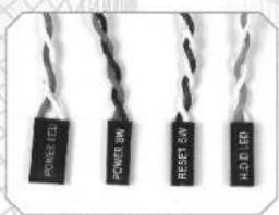
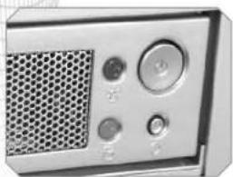
On the front of the case, you can find some LEDs and switch leads (POWER SW*1, POWER LED*1, H.D.D. LED*1, RESET SW*1, SPEAKER*1).
Please consult user manual of your motherboard manufacturer, then connect these leads to the panel header on the motherboard. These leads are usually labeled; if not, please trace them back to the case front to find out their source.
- POWER LED
connects to your M/B at the PLED.
- POWER SW
connects to the PWR connector on the motherboard.
-H.D.D LED
connects to the 2-pin labeled HDD LED connector.
- RESET SW
connects to the RSW connector on the motherboard.
- SPEAKER
find out the 4-pin labeled SPEAKER on the M/B then connect it.
natural_image
Close-up of a vintage electronic device with a mesh grille and control buttons (no visible text or symbols)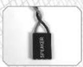
3.3 USB2.0 & IEEE1394 Firewire connection
USB connection
Please consult your motherboard manual to find out the section of "USB connection".
| USB2.0 connection | ||||
| M/B layout (Ex: ASUS) | Case layout | |||
| 1 | USB+5V | VCC 1 | Red | USB 1 |
| 2 | LDM1 | DATA-1 | White | |
| 3 | LDP1 | DATA+1 | Green | |
| 4 | GND | GND 1 | Black | |
| 5 | NC | SHIELD 1 | Black | |
| 6 | USB+5V | VCC 2 | Red | USB 2 |
| 7 | LDM2 | DATA-2 | White | |
| 8 | LDP2 | DATA+2 | Green | |
| 9 | GND | GND 2 | Black | |
| 10 | -- | SHIELD 2 | Black | |
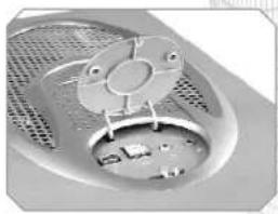
natural_image
Close-up of a computer fan with ventilation grille and internal components (no visible text or symbols)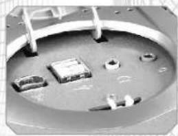
natural_image
Close-up of a mechanical component with multiple holes and a central circular base (no visible text or symbols)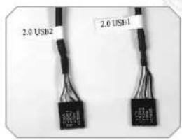
IEEE1394 Firewire connection
Please consult your motherboard manual to find out the section of "IEEE1394 Firewire connection".
| 1394 Firewire connection | |||
| M/B layout (Ex. ASUS) | Case layout | ||
| 1 | +12V | VP | White |
| 2 | Ground | VG | Black |
| 3 | TPB- | TPB- or TPB* | Red |
| 4 | TPB+ | TPB+ or TPB | Green |
| 5 | TPA- | TPA- or TPA* | Orange |
| 6 | TPA+ | TPA+ or TPA | Blue |
| 7 | Ground | Ground | Black |
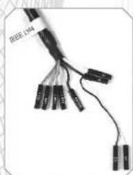
natural_image
Coiled black cable with multiple connectors and a separate terminal block (no visible text or symbols)3-4 Audio Connection
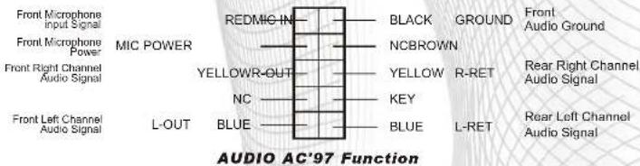
- Please refer to the following illustration of Audio connector and your motherboard user manual.
- Please select the motherboard which used AC'97 or HD Audio (Azalia), (be aware of that your audio supports AC'97 or HD Audio (Azalia)) or it will damage your device(s).
- On some motherboards, the connectors for Audio are not the same as the drawing below. Please check with your motherboard manual before installing.
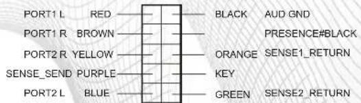
AUDIO AZALIA Function
3.5 Case open alarm function (Intrusion switch)

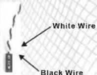
To find out the cable with 2pin connector (Micro SW) from the rear of inside the chassis.

To find out the position of Chassis Alarm on your motherboard. (please consult your motherboard manual)

- Contents
- Chapter1 Product Introduction
- Chapter2 Case Mechanical Operation
- Chapter3 Motherboard & Leads Installation
- Notice
- How to open the side panel
- Installing 5.25" Device
- Installing 3.5" HDD
- Removable 12cm Fan cage with 3HDD
- Installing 3.5" HDD (For 12cm Fan Cage)
- 5.25" to 3.5" Drive Tray Device Installation.
- Installing Power Supply
- PCI slot tool-free function operation
- Motherboard Installation
- Placement Direction:
- Case LED connections
- USB2.0 & IEEE1394 Firewire connection
- USB connection
- IEEE1394 Firewire connection
- 3-4 Audio Connection
- Case open alarm function (Intrusion switch)
Brand : THERMALTAKE
Model : Armour VA8004
Category : Computer Case