
Wing RS 100 - Computer Case THERMALTAKE - Free user manual and instructions
Find the device manual for free Wing RS 100 THERMALTAKE in PDF.


| Product Type | Computer Case |
| Model | Wing RS 100 |
| Brand | Thermaltake |
| Form Factor | Mid Tower |
| Motherboard Support | ATX, Micro-ATX, Mini-ITX |
| Dimensions (H x W x D) | 480 mm x 220 mm x 440 mm |
| Weight | Approx. 5.5 kg |
| Material | Steel, Plastic, Tempered Glass Side Panel |
| Color | Black |
| Expansion Slots | 7 |
| Drive Bays | 2x 3.5", 2x 2.5" (internal) |
| Cooling Support | Front: 3x 120mm or 2x 140mm; Top: 2x 140mm; Rear: 1x 120mm |
| Radiator Support | Front: 360mm; Top: 280mm; Rear: 120mm |
| PSU Form Factor | Standard ATX (bottom mount) |
| Front I/O Ports | 2x USB 3.0, Audio/Mic |
| Maximum GPU Length | Up to 320 mm |
| Maximum CPU Cooler Height | Up to 160 mm |
| Cleaning Instructions | Use a soft dry cloth to clean exterior. Avoid liquids. Unplug before cleaning. |
| Safety Warnings | Keep away from moisture and heat sources. Ensure proper ventilation. Do not open PSU. |
| Spare Parts & Repairability | Contact Thermaltake support for replacement parts. Case components are user-replaceable. |
| General Information | Designed for gaming and high-performance builds. Supports RGB lighting control via motherboard. |
Frequently Asked Questions - Wing RS 100 THERMALTAKE
User questions about Wing RS 100 THERMALTAKE
0 question about this device. Answer the ones you know or ask your own.
Ask a new question about this device
Download the instructions for your Computer Case in PDF format for free! Find your manual Wing RS 100 - THERMALTAKE and take your electronic device back in hand. On this page are published all the documents necessary for the use of your device. Wing RS 100 by THERMALTAKE.
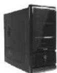
USER MANUAL Wing RS 100 THERMALTAKE
Thermaltake Coolall YOUR LIFE
©2007 Thermaltake Technology Co., Ltd. All Rights Reserved. 2007.04 All other registered trademarks belong to their respective companies.www.thermaltake.com
FCC Trusted To Comply With FCC Standards FOR HOME OR OFFICE USE

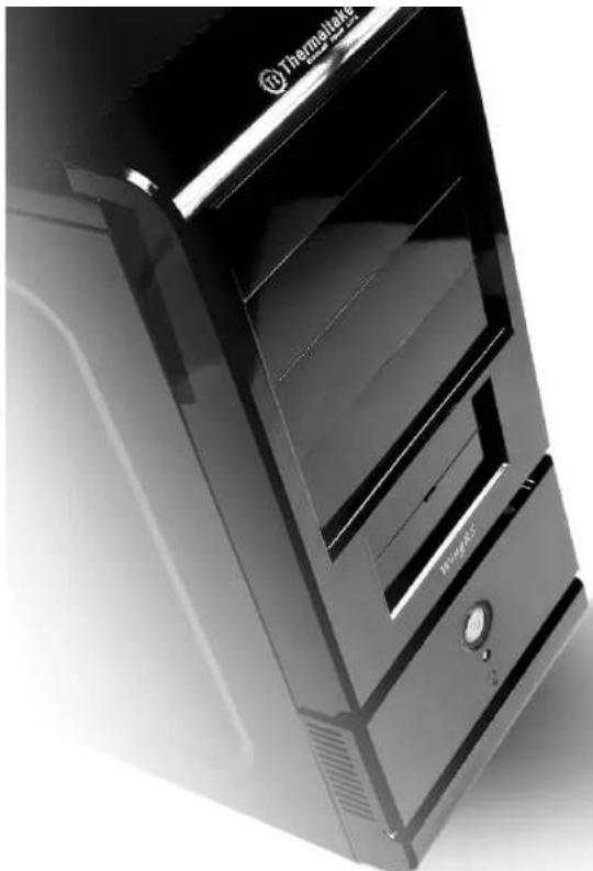
natural_image
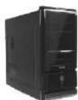
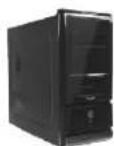
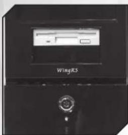
Close-up of a black Thermostek desktop computer tower case (no visible text or symbols on the device body)Wing RS 100 User's Manual

Thermaltake
COOLALL YOUR LIFE VG1000BNS
Contents
Chapter 1. Product Introduction
1-1 Specification 02
Chapter 2. Case Mechanical Operation
2-1 How to open the side panel 03
2-2 External 5.25" device installation 04
2-3 External 3.5" device installation 07
2-4 HDD installation 10
2-5 Front fan installation (Optional) 11
2-6 PCI slot usage 12
2-7 How to install PSU 14
Chapter3 Motherboard & Lends Installation
3-1 Motherboard installation 15
3-2 Case LED connections 16
3-3 USB2.0 connection 17
3-4 Audio connection 18
Chapter4 RSI Cooler and Power Supply
4-1 RSI Cooler (Optional) 19
4-2 RSI Power Supply (Optional) 20
Wing RS 100
VG1000BNS
Chapter 1. Product Introduction
Specification
| Model | VG1000BNS |
| Case Type | Middle Tower |
| Net Weight | 4.75 kg; 10.47 lb |
| Dimension (H*W*D) | 440 x 190 x 480 mm17.3 X 7.5 X 18.9 inch |
| Cooling System | Front (Intake):120 x 120 x 25 mm (optional)Rear (Exhaust):120 x 120 x 25 mm, 1300rpm, 17dBA |
| Drive Bays - Accessible - Hidden | 104 x 5.25", 1 x 3.5"5 x 3.5" |
| Material | SECC |
| Color | Black |
| Expansion Slots | 7 |
| Motherboards | Micro ATX, Standard ATX |
| I/O Ports | Dual USB 2.0, MIC & Speaker |

Chapter 2. Case Mechanical Operation
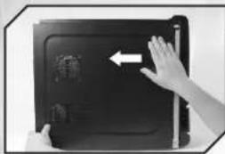
2.1 How to open the side panel
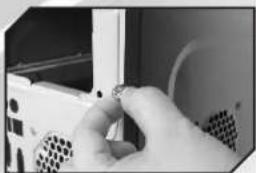
natural_image
Close-up of hands holding a small object inside a computer case (no visible text or symbols)1
To remove the side panel, please remove upper and bottom thumb screws on the back of the case.
natural_image
Close-up of hands interacting with a black tablet device, showing a screen with a white arrow pointing to it (no visible text or symbols)2
natural_image
Exterior view of an open electrical control cabinet with visible wiring and components (no text or symbols)3
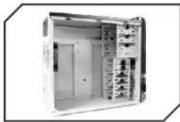
Remove the side panel, please refer to the orientation of the picture.
Open the side panel
natural_image
Close-up of a hexagonal mesh structure with a tool interacting with it (no visible text or symbols)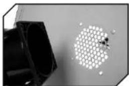
natural_image
Close-up of a hexagonal patterned object with small white spheres, next to a dark rectangular object (no text or symbols visible)Important Notice:
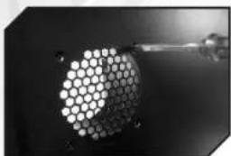
If the air guide interferes with CPU cooling fan, please remove the CPU air guide as shown.
3
Wing RS 100
VG1000BNS
2-2 External 5.25" device installation
natural_image
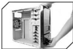
Interior view of a computer tower with visible fan and drive slots (no text or symbols)1
Remove the front panel
natural_image
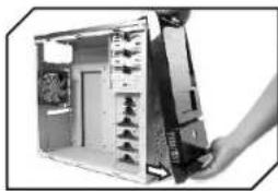
Close-up of a computer tower with visible drive bays and fan array (no text or symbols)2
Pull out the front panel as shown
natural_image
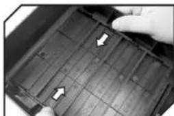
Close-up of a hand holding a black plastic tray with white arrows indicating flow or movement (no text or symbols visible)3
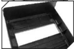
Remove the 5.25" drive bay plastic cover
natural_image
Black plastic enclosure with a rectangular opening and horizontal slot (no text or symbols visible)4
natural_image
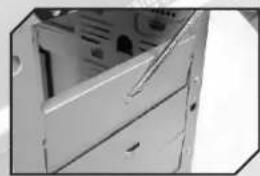
Close-up of a computer tower case with visible internal components (no text or symbols)4
Remove the 5.25" drive bay metal cover
natural_image
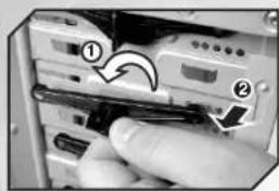
Close-up of a hand inserting a USB into a computer drive (no visible text or symbols)5
Turn lock device counterclockwise to unlock
natural_image
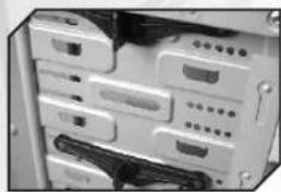
Close-up of a computer tower rear panel with multiple drive bays and cables (no visible text or labels)6
Remove lock device
natural_image
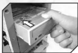
Close-up of a hand inserting a CD into a drive (no visible text or symbols)7
Place 5.25" device into the drive bay
natural_image
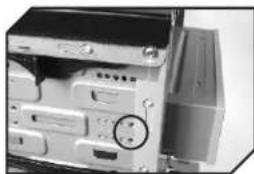
Close-up of a computer monitor with a circular button on the left side (no visible text or symbols)8
Find the proper openings
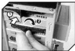
9
Put back the lock device and turn lock device clockwise to lock
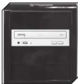
10
5.25" device installation complete
Wing RS 100
VG1000BNS

2-3 External 3.5" device installation
natural_image
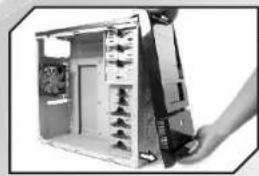
Close-up of a computer tower case with visible internal components and a hand adjusting the case (no text or symbols)1
Pull out the front panel as shown
natural_image
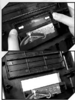
Close-up of hands installing a battery cover into a device (no visible text or symbols)2
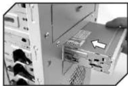
Remove the 3.5" drive bay plastic cover
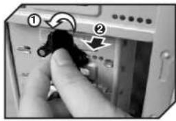
3
Turn lock device counterclockwise to unlock
natural_image
Close-up of a computer tower with an open drive unit and cable rack (no visible text or symbols)4
Remove lock device and insert the device into the 3.5" drive bay
natural_image
Interior view of a computer tower case showing drive bays and socket (no visible text or labels)5
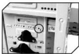
Find the proper openings
7
Wing RS 100
VG1000BNS

8
7
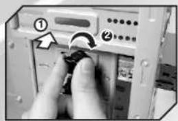
Put back the lock device and turn clockwise to secure the drive
8
3.5" device installation complete
Important Notice:
The lower 3.5" external drive bay is not compatible with FDD, but HDD is able to be installed in it. While installing HDD, please remove the tool-free kit and secure HDD by screws.
2.4 HDD installation
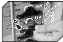
1
Turn lock device counterclockwise to unlock
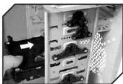
natural_image
Close-up of a computer tower case with visible internal components and a hand holding a device (no text or symbols)2
Remove lock device then place HDD into drive bay
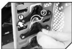
3
Put back the lock device and turn lock device clockwise to secure the HDD
Wing RS 100
VG1000BNS
2.5 Front fan installation (optional)
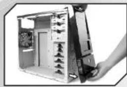
natural_image
Interior view of a computer tower case with visible socket and drive mechanism (no text or labels)1
Remove the front panel
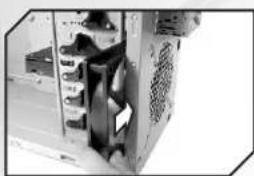
natural_image
Interior view of a computer tower case showing internal components and ventilation duct (no visible text or labels)2
Place the fan as shown
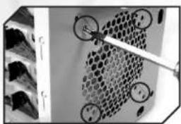
natural_image
Close-up of a mechanical component with circular holes and a tool, no visible text or symbols3
Secure the fan by screws
2-6 PCI slot usage
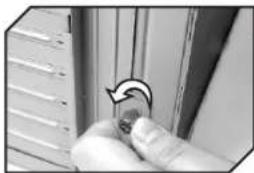
natural_image
Close-up of a hand holding a small circular object with an arrow indicating rotation (no text or symbols visible)1
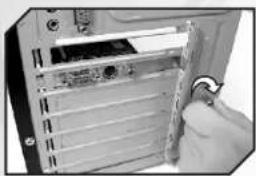
Remove thumb screw from PCI slot bracket
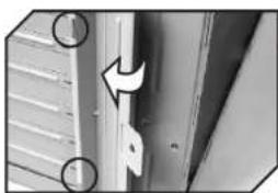
natural_image
Close-up of a door handle with a white arrow indicating rotation, no visible text or symbols2
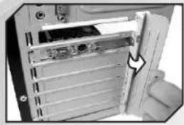
Take off the PCI slot bracket as shown
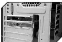
natural_image
Front view of a computer tower case with drive bays and ventilation slots (no visible text or labels)3
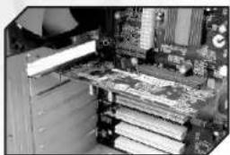
Insert the PCI device into PCI slot
11
Wing RS 100
VG1000BNS
12
natural_image
Close-up of a computer tower drive showing internal components and a hand holding the door (no text or symbols visible)4
Put back the PCI slot bracket
natural_image
Close-up of a computer tower with a hand holding a cable inserted (no visible text or symbols)5
Screw the thumb screw as shown
natural_image
Interior view of a computer motherboard with CPU socket and RAM slots (no visible text or labels)6
Finish installation
13
Wing RS 100
VG1000BNS
2-7 How to install PSU
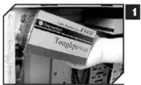
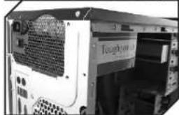
natural_image
Exterior view of a computer tower case with ventilation grille and drive door (no visible text or symbols)Place the PSU over the location as shown
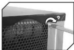
natural_image
Close-up of a black metal panel with a grid pattern and a tool inserted, no visible text or symbols2
Secure it by screws
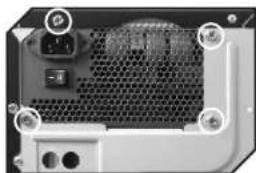
natural_image
Close-up of a computer tower rear panel showing ventilation grille and drive buttons (no text or symbols visible)3
Finish installation
14
Chapter.3 Motherboard & Leads Installation
3.1 Motherboard Installation
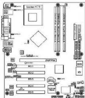
Each motherboard has different standoff layout. It is highly suggested that you refer to your motherboard's manual when installing motherboard into the Case. The cases are applicable with Standard ATX, Micro ATX motherboards. Your motherboard may require a special I/O Panel, which should be included with your motherboard.
Placement Direction:
When installing the motherboard, make sure you follow the direction provided by your motherboard manufacturer. On most standard motherboards, the edge with external ports goes to the rear part of the chassis. It is highly recommended that you install CPU, heat sink and modular components before fixing the motherboard inside the chassis.
Note :
Due to the variety of motherboards on the market, the majority of the motherboards come with their own I/O plates. It's necessary for you to remove the fan holder before install the I/O plates.

This side towards the rear of the chassis

flowchart
graph TD
    A["Socket 470"] --> B["PLC1"]
    A --> C["PLC2"]
    A --> D["PLC3"]
    A --> E["PLC4"]
    A --> F["PLC5"]
    B --> G["Control Unit"]
    C --> H["Data Bus"]
    D --> I["Storage System"]
    E --> J["Control Unit"]
    F --> K["Data Bus"]
    G --> L["IO"]
    H --> M["IO"]
    I --> N["IO"]
    J --> O["IO"]
    K --> P["IO"]
The locations of the screw holes. Note these locations and place included standoffs on the chassis first.
Above Illustration is a sample of what the motherboard's layout. For more detail screw hole placement, please refer to your motherboard manual.
Wing RS 100
VG1000BNS
3-2 Case LED connections
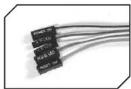
On the front of the case, you can find some LEDs and switch leads (POWER SW*1, POWER LED*1, H.D.D. LED*1, RESET SW*1).
Please consult user manual of your motherboard manufacturer, then connect these leads to the panel header on the motherboard. These leads are usually labeled; if not, please trace them back to the case front to find out their source.
- POWER LED
connects to your M/B at the PLED
- POWER SW
connects to the PWR connector on the motherboard.
- H.D.D LED
connects to the 2-pin labeled HDD LED connector.
- RESET SW
connects to the RSW connector on the motherboard,
natural_image
Close-up of four black electronic components with coiled wires, no visible text or symbols3-3 USB2.0 connection 3
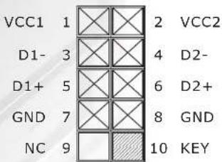
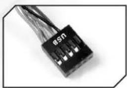
USB connection
Please consult your motherboard manual to find out the section of "USB connection".
USB
natural_image
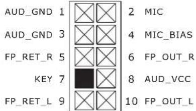
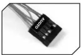
Close-up of a black electronic component with wires, no visible text or symbolsPlease consult your motherboard manual to find out the section of "front panel audio connector".
AUDIO
natural_image
Close-up of a black electronic component with multiple wires extending outward (no visible text or symbols)
Wing RS 100
VG1000BNS

Chapter.4 RSI Cooler and Power Supply
4-1 RSI Cooler (Optional)
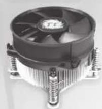
natural_image
Close-up of a CPU fan with cooling fins and three screws (no visible text or symbols)PIN : CL-P0441
Designed for Intel Core 2 Duo Processor Application for Intel Core 2 Duo / Pentium D / Celeron series (Socket LGA775)
FEATURES:
- Aluminum Crotch Fin provides more heat dissipation area.
- Silent operation. Optimized solution for low power processors.
- Back plate & Spring Screw mounting method ensure safe installation when shipping.
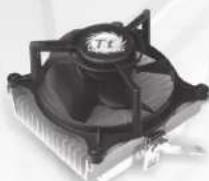
PIN : CL-P0444
Application for AMD Athlon 64 X2/Athlon 64 FX/ Athlon 64(Socket AM2/ 939/754) and Sempron (Socket AM2/754)
FEATURES :
- Perfect ratio aluminum extrusion heatsink for better heat dissipation.
- Tool-less clip, easy installation.
- Silent Solution
4-2 RSI Power Supply (Optional)
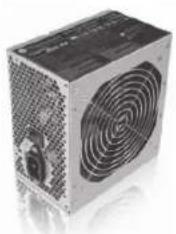
Litepower
400W
natural_image
Exterior view of a computer power supply unit with visible cooling fan and ventilation grille (no text or symbols)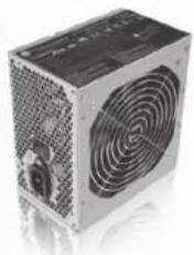
natural_image
Exterior view of a computer power supply unit with visible fan blades (no text or symbols)PIN: W0161 WIPFC PIN: W0162 No PFC
FEATURES:
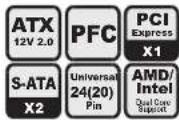
- Intel ATX 12V 2.0 Compatible.
- Supports 6-pin PCI-Express, 2 SATA, and 20+4 pin connector.
- Dual +12V output circuit provides steady output for system.
- Super quiet and stable 12cm ball bearing fan.
- Build-in Over Current Protection, Over Voltage protection, and Short-Circuit protection.
- Safety : UL, CUL, CE, NEMKO, TUV+CB, BSMI, FCC certification.
There are recommended products of Thermaltake PSU, please refer to http://www.thermaltake.com
Wing RS 100
VG1000BNS
memo memo
21
Wing RS 100
VG1000BNS
22
- Thermaltake Coolall YOUR LIFE
- Wing RS 100 User's Manual
- Contents
- Chapter 1. Product Introduction
- Chapter 2. Case Mechanical Operation
- Chapter3 Motherboard & Lends Installation
- Chapter4 RSI Cooler and Power Supply
- Specification
- How to open the side panel
- Important Notice:
- 2-2 External 5.25" device installation
- 2-3 External 3.5" device installation
- HDD installation
- Front fan installation (optional)
- 2-6 PCI slot usage
- 2-7 How to install PSU
- Chapter.3 Motherboard & Leads Installation
- Motherboard Installation
- Placement Direction:
- Note :
- 3-2 Case LED connections
- 3-3 USB2.0 connection 3
- USB connection
- Chapter.4 RSI Cooler and Power Supply
- 4-1 RSI Cooler (Optional)
- PIN : CL-P0441
- FEATURES:
- PIN : CL-P0444
- FEATURES :
- 4-2 RSI Power Supply (Optional)
- Litepower
- 400W
- PIN: W0161 WIPFC PIN: W0162 No PFC
Brand : THERMALTAKE
Model : Wing RS 100
Category : Computer Case