Armour LCS VE2000 - Computer Case THERMALTAKE - Free user manual and instructions
Find the device manual for free Armour LCS VE2000 THERMALTAKE in PDF.


| Brand | Thermaltake |
| Model | Armour LCS VE2000 Series (VE2000SWA / VE2000BWS) |
| Product Type | Super Tower Computer Case |
| Side Panel | Transparent Window |
| Dimensions (HxWxD) | 530 x 220 x 560 mm |
| Net Weight | 13.87 kg (SWA) / 21.08 kg (BWS) |
| Material | All Aluminum (SWA) / Chassis: 1.0 SECC, Front Bezel: Aluminum (BWS) |
| Color | Silver (SWA) / Black (BWS) |
| Cooling System | Front (intake): Dual 120x120x25 mm Blue LED fans, 1300rpm, 17dBA; Rear (exhaust): 120x120x25 mm Blue LED fan, 1300rpm, 17dBA + 90x90x25 mm fan, 1800rpm, 19dBA; Top (exhaust): 90x90x25 mm fan, 1800rpm, 19dBA |
| Drive Bays - Front Accessible | 14 x 5.25", 1 x 3.5" |
| Drive Bays - Internal | 10 x 3.5" |
| Expansion Slots | 7 |
| Supported Motherboards | Micro ATX, ATX, Extend ATX, BTX (BTX Upgrade Kit optional) |
| Power Supply Type | Standard ATX PSII |
| I/O Ports | USB 2.0 x2, IEEE 1394 x1, HD Audio & Speaker ports |
| Liquid Cooling System | All-in-one waterblock (Intel BTX, P4 775, AMD K8), 240mm radiator with dual 120mm fans, P500 DC 12V pump (500L/hr), reservoir (350cc), UV tube 3/8" |
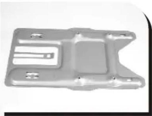
| BTX Upgrade Kit | Optional (P/N: A9358) - SRM/Rear plate |
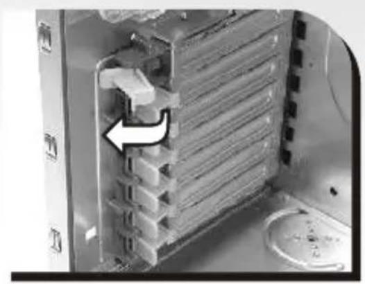
| Tool-free Features | 5.25" device installation, 3.5" HDD cage, PCI slot clips |
| Additional Features | Case open alarm, removable HDD cage, fan holders on top |
Frequently Asked Questions - Armour LCS VE2000 THERMALTAKE
User questions about Armour LCS VE2000 THERMALTAKE
0 question about this device. Answer the ones you know or ask your own.
Ask a new question about this device
Download the instructions for your Computer Case in PDF format for free! Find your manual Armour LCS VE2000 - THERMALTAKE and take your electronic device back in hand. On this page are published all the documents necessary for the use of your device. Armour LCS VE2000 by THERMALTAKE.
USER MANUAL Armour LCS VE2000 THERMALTAKE
© 2006 Thermaltake Technology Co., Ltd. All Rights Reserved.
All other registered trademarks belong to their respective companies.
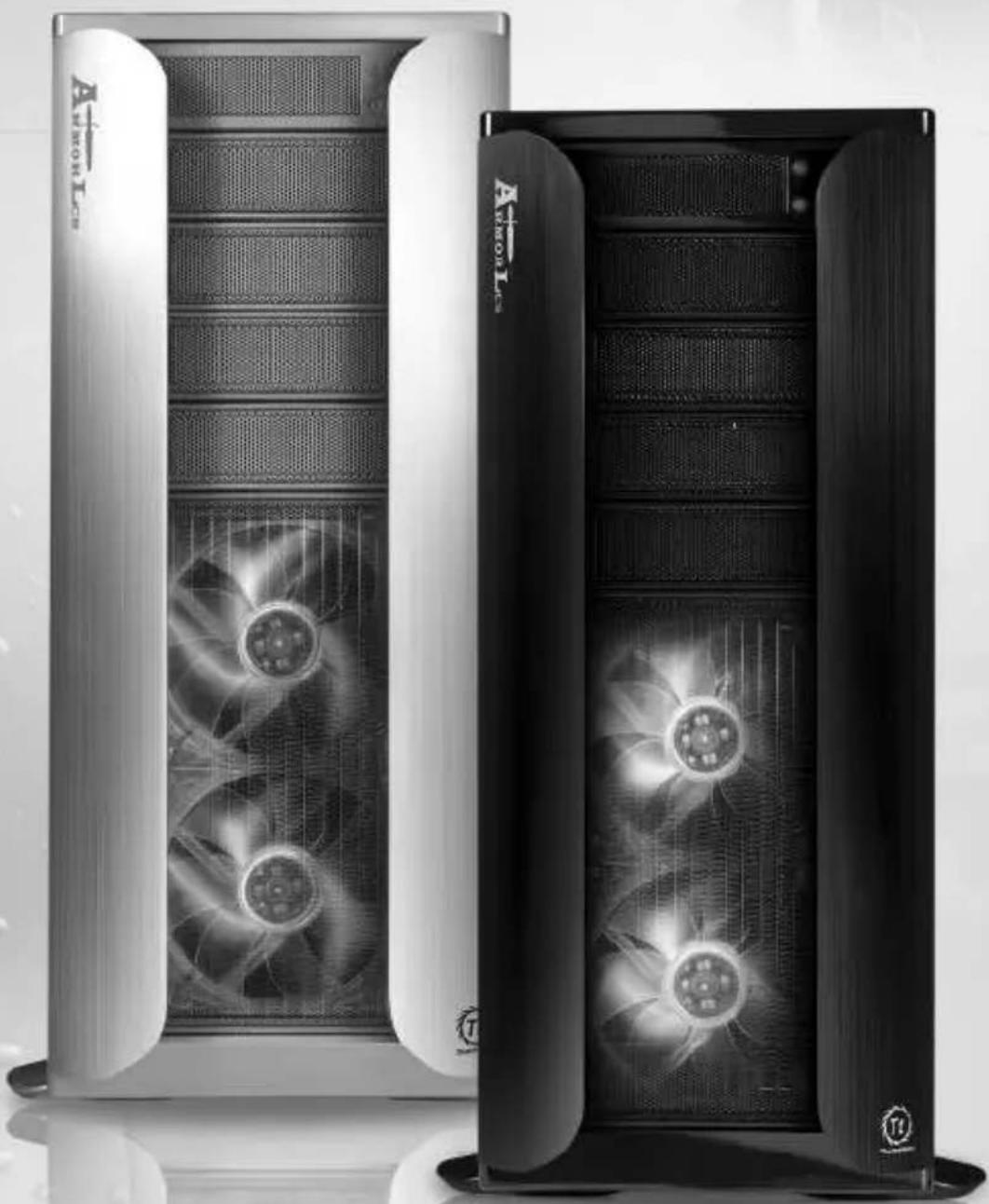
ARMOR LCS
VE2000 Series
User's Manual
natural_image
Two black-and-white photos of a server tower with visible fan blades and ventilation grilles, no text or symbols present.Limited Liability
These warranties replace all other warranties, expressed or implied including, but not limited to, the implied warranties of merchantability and fitness for a particular purpose.
Thermaltake disclaims all other warranties, expressed or implied including, without limitation, implied warranties of merchantability and fitness for a particular purpose.
Some jurisdictions do not allow the exclusion of implied warranties so this limitation may not apply to you. All expressed and implied warranties are limited in duration to the limited warranty period. No warranties apply after that period, some jurisdiction do not allow limitation on how long an implied warranty lasts, so this limitation may not apply to you.
Limitations of liability, Thermaltake's responsibility under this, or any other warranty, implied or expressed, are limited to repair or replacement, as set forth above. These remedies are the sole and exclusive remedies for any breach of warranty. Thermaltake is not responsible for direct, special, incidental, or consequential damages resulting from any breach of warranty or under any other legal theory including, but not limited to, lost profits, downtime, goodwill, damage to or replacement of equipment and property, and any cost of recovering, reprogramming, or reproducing any program or data stored in or used with a system containing Thermaltake product. Some jurisdictions do not allow the exclusion or limitation of incidental or exclusions may not apply to you.
Extent of limited warranty, Thermaltake does not warrant that your product will be free from design defects or errors known as "ERRATA". Current characterized errata are available upon request. This limited warranty does not cover any costs relating to removal or replacement of any part that is soldered or otherwise affixed to your system's motherboard. This limited warranty does not cover damages due to external causes, including accidental, problems with electrical power, usage not in accordance with product instructions, misuse, neglect, alteration, repair, improper installation, or improper testing. Nor is Thermaltake held liable for any bodily damage that may result during the installation, maintenance, repair, or is otherwise associated with this product, Thermaltake is free from any legal actions that may result in death, pain and anguish, or any other form of personal damage that may occur by purchasing this product.
You, the buyer, agree to this warranty and its term set within its expressed and implied limited warranty. This limited warranty gives you specific legal rights, and you may also have other right that varies from jurisdiction to jurisdiction.
Chapter 1. Product Introduction
1.1 Specification 04
Chapter 2. Case Mechaniacl Operation
2.1 How to open the side panel 05
2.2 Installing 5.25" Device 06
2.3 Installing 3.5" HDD 07
2.4 HDD installation 08
2.5 Installing 3.5" Device to Drive Tray With Power Button 11
2.6 Installing Power Supply 13
2.7 Installing the Fan on Top of the Case 14
2.8 How to Remove the Fan & fan holder 15
2.9 Air Cooling System 16
2.10 BTX Upgraded Kits 17
2.11 PCI slot tool-free function operation 18
Chapter3 Motherboard & Leads Installation
3.1 Motherboard Installation 19
3.2 Case LED connections 21
3.3 USB2.0 & IEEE1394 Firewire connection 22
3.4 Ear & MIC connections 23
3.5 Case open alarm function 24
Chapter4 Other
4.1 Silent Purepower ^TM power supply(optional) 25
Chapter 5. Liquid Cooling Installation
5.1 Specification 26
5.2 Components 27
5.3 Installation steps 28
5.4 Install Waterblock 29
-5.4.1 Clip the Waterblock on CPU (Inter P4 LGA775) .. 29
-5.4.2 Clip the Waterblock on CPU (AMD K8) 32
-5.4.3 Clip the Waterblock on CPU (Intel BTX Platform) 38
5.5 Install Pump & Tank 40
5.6 Install Water tube 41
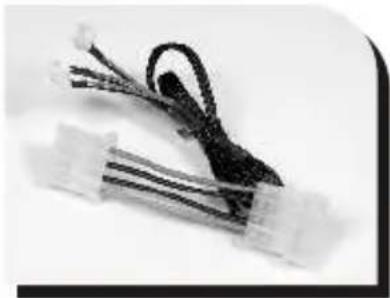
5.7 Connect the Front Fan to Power Supply 46
5.8 Fill Coolant 47
5.9 Q & A 49
natural_image
Interior view of a desktop computer tower case showing internal circuitry and ventilation ducts (no visible text or labels)VE2000SWA
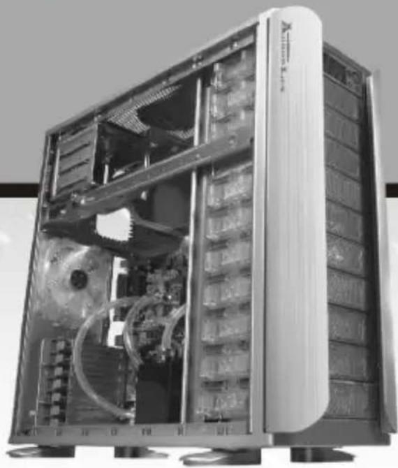
| Model | VE2000SWA |
| Case Type | Super Tower |
| Side Panel | Transparent Window |
| Net Weight | 13.87 kg |
530 X 220 X 560 mm
Dimension (H*W*D)
| Cooling System | Front (intake)Dual 120 x120 x 25 mm,Blue LED Fan, 1300rpm, 17dBARear (exhaust)120 x 120 x 25 mm, blue LED fan,1300rpm, 17dBA;90 x 90 x 25mm, 1800rpm, 19dBATop (exhaust)90 x 90 x 25mm, 1800rpm, 19dBA |
| Drive Bays-Front accessible-Internal | 114 x 5.25" 1 x 3.5"10 x 3.5" |
Material
All Aluminum
| Color | Silver |
| Expansion Slots | 7 |
| Motherboards | Micro ATX, ATX, Extend ATX, BTXBTX Upgrade Kits SRM/Rear plate (optional) |
| PSU | Standard ATX PSII |
| I/O Ports | USB 2.0 x 2, IEEE 1394 x 1, HD Audio & Speaker ports |
| BTX Upgrade Kit | SRM/Rear plate (option: A9358) |
| Liquid Cooling System | All-in-one waterblock :For Intel BTX platform, P4 775 and AMD K8Performance radiator :(A) Dimension of radiator :120(W) mm x 240(D) mm(B) Two 1300RPM 120mm fansP500 liquid pump :Power DC 12V liquid pump (500L/hr)Reservoir :Contains 350 c.c. of liquid capacity, easy to refillWater tube :Transparent UV tube (3/8") & industrial-grade rubber tube (pre-assembled) |
VT2000BWS
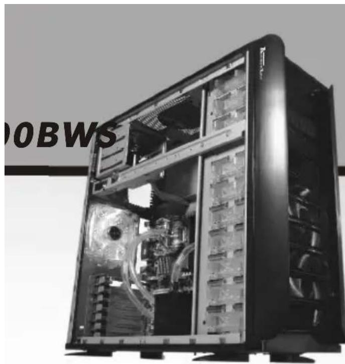
| Model | VE2000BWS |
| Case Type | Super Tower |
| Side Panel | Transparent Window |
| Net Weight | 21.08 kg |
| Dimension (H*W*D) | 530 X 220 X 560 mm |
| Cooling System | Front (intake)Dual 120 x120 x 25 mm,Blue LED Fan, 1300rpm, 17dBARear (exhaust)120 x 120 x 25 mm, blue LED fan,1300rpm, 17dBA;90 x 90 x 25mm, 1800rpm, 19dBATop (exhaust)90 x 90 x 25mm, 1800rpm, 19dBA |
| Drive Bays-Front accessible-Internal | 114 x 5.25" 1 x 3.5"10 x 3.5" |
| Material | Chassis:1.0 SECCFront Bezel: Aluminum |
| Color | Black |
| Expansion Slots | 7 |
| Motherboards | Micro ATX, ATX, Extend ATX, BTXBTX Upgrade Kits SRM/Rear plate (optional) |
| PSU | Standard ATX PSII |
| I/O Ports | USB 2.0 x 2, IEEE 1394 x 1,HD Audio & Speaker ports |
| BTX Upgrade Kit | SRM/Rear plate (option: A9358) |
Liquid Cooling System
All-in-one waterblock :
For Intel BTX platform, P4 775 and AMD K8
Performance radiator :
(A) Dimension of radiator :120(W) mm x 240(D) mm
(B) Two 1300RPM 120mm fans
P500 liquid pump :
Power DC 12V liquid pump (500L/hr)
Reservoir :
Contains 350 c.c. of liquid capacity, easy to refill
Water tube :
Transparent UV tube (3/8") & industrial-grade rubber tube (pre-assembled)
Chapter2 Case Mechanical Operation
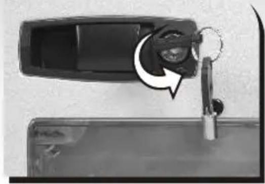
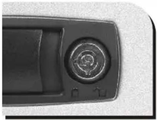
2.1 How to open the side panel
natural_image
Close-up of a car door handle with a key inserted, showing a circular arrow indicating rotation (no text or symbols)To find out the side panel key from the back side of the case then open it as the picture.
natural_image
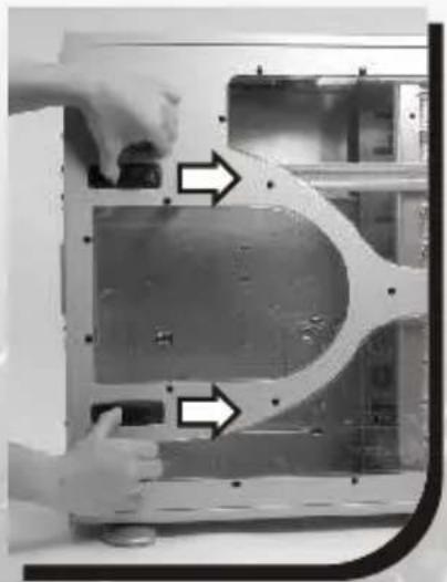
Close-up of a black mechanical component with a circular button and adjustment knob (no visible text or symbols)← Make sure the side panel lock is opened.
natural_image
Close-up of hands installing or adjusting a metal panel inside a device casing (no visible text or symbols)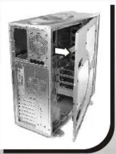
natural_image
Exterior view of a computer tower case showing internal components and ventilation duct (no text or symbols visible)← Push the button then swing out the side panel.
2.2 Installing 5.25" Device
natural_image
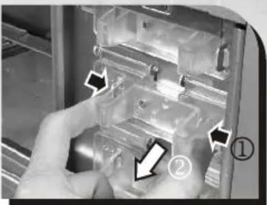
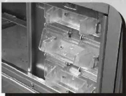
Interior view of a stainless steel enclosure with transparent plastic panels and metal casing (no visible text or symbols)Squeeze and pull out-ward the tool-free clip
natural_image
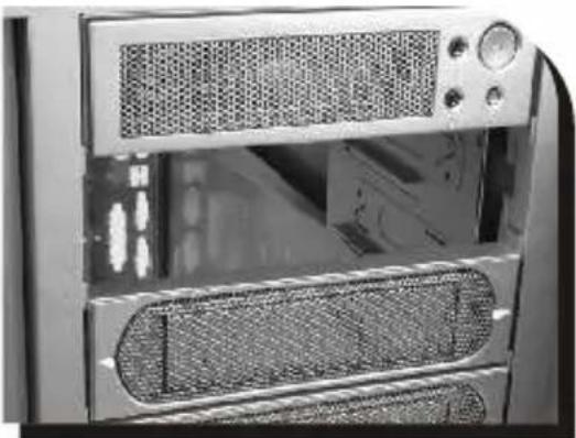
Close-up of a microwave oven with ventilation grilles and control panel (no visible text or symbols)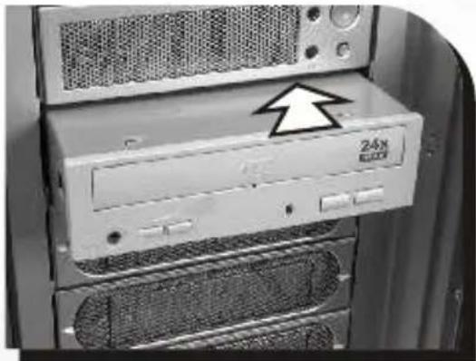
natural_image
Close-up of a CD-ROM drive with a 24x power strip, showing front panel and rack (no text or symbols on the device itself)Remove the drive bay cover from the selected position, then insert the device into the 5.25" drive bay
natural_image
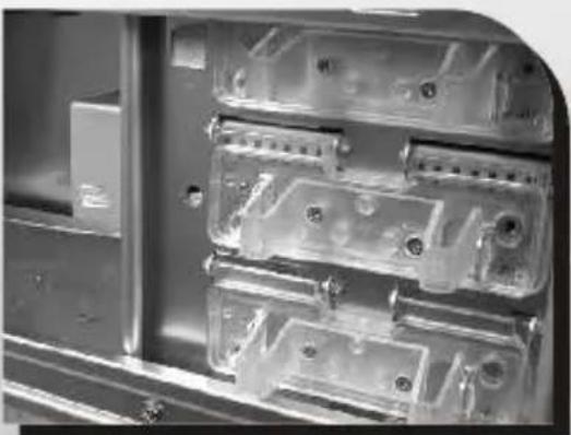
Close-up of a transparent plastic electrical enclosure with multiple compartments and mounting holes (no visible text or symbols)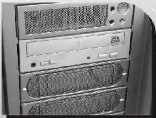
natural_image
Front view of a desktop computer tower rack with ventilation grilles and drive bays (no visible text or labels)Squeeze and push in-ward the tool-free clip.
Finish installation
2.3 Installing 3.5" HDD
natural_image
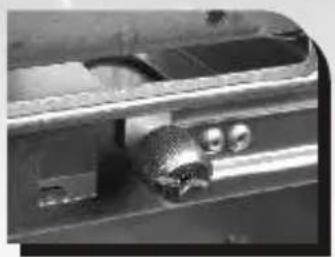
Close-up of a mechanical component with a textured surface and circular features (no visible text or symbols)← Unscrew the thumb screw for removable HDD cage
natural_image
Close-up of a computer tower with a hand inserting a drive into the case (no visible text or symbols)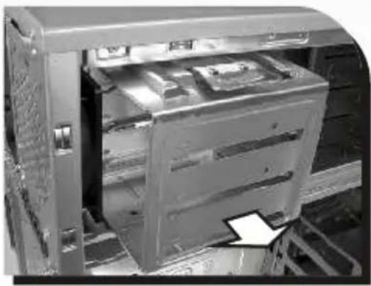
natural_image
Interior view of a computer tower with visible drive bays and a paper clip (no text or symbols)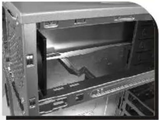
natural_image
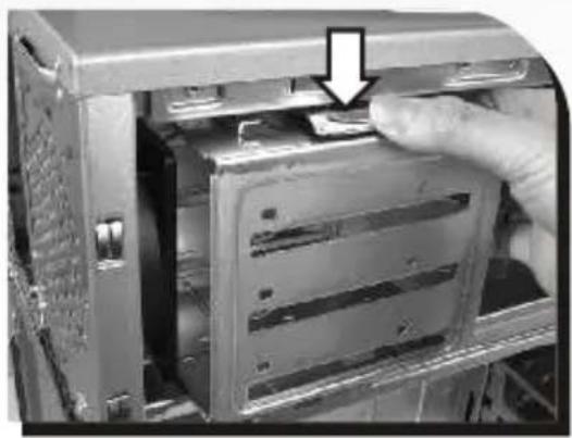
Interior view of a server rack cabinet showing internal components and ventilation ducts (no visible text or labels)←Push down and hold the metal tab, then pull the HDD cage out-ward to remove from chassis.
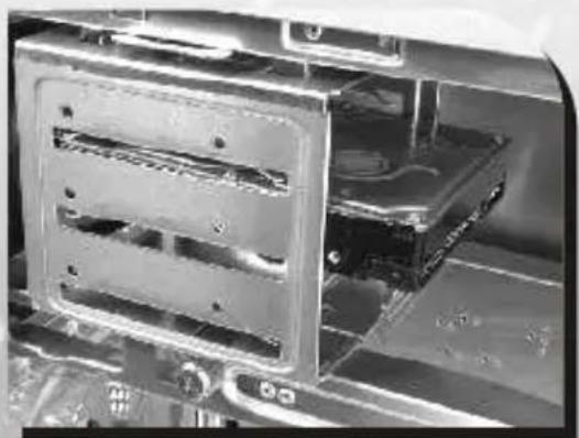
natural_image
Close-up of a mechanical assembly with internal components and mounting holes (no visible text or symbols)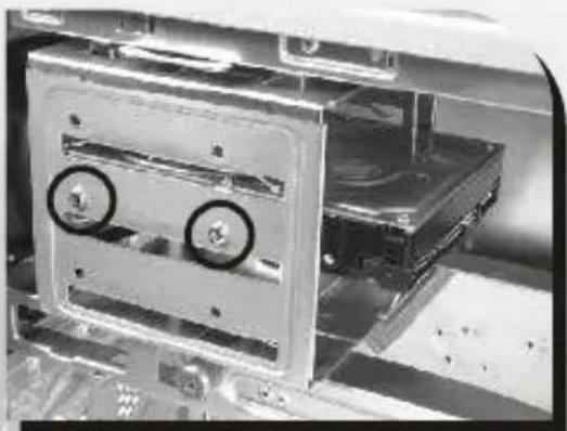
natural_image
Close-up of a mechanical device with two wheels mounted on a metal frame (no visible text or symbols)↑ Secure HDD with Screw
2.4 HDD installation
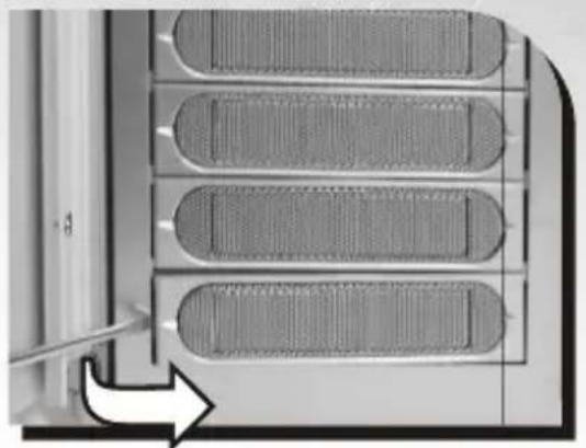
natural_image
Close-up of a mechanical component with four rectangular slots and a curved handle, showing no text or symbols.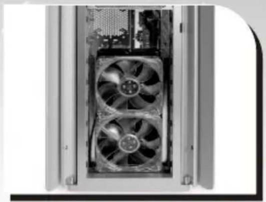
natural_image
Close-up of a computer tower case showing two internal fans with cooling effect (no text or symbols visible)↑ Remove the drive bay covers as shown.
natural_image
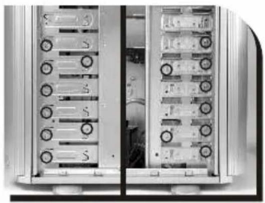
Interior view of a dual-chamber server rack unit with multiple drive bays and circular buttons (no visible text or labels)Remove screws on both side of the cage as shown.
Note:
These screws here are for security consideration during shipment.
natural_image
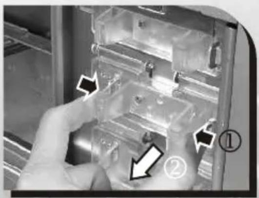
Interior view of a refrigerator showing internal compartments and storage areas (no visible text or labels)Squeeze and pull out-ward the tool-free clips.
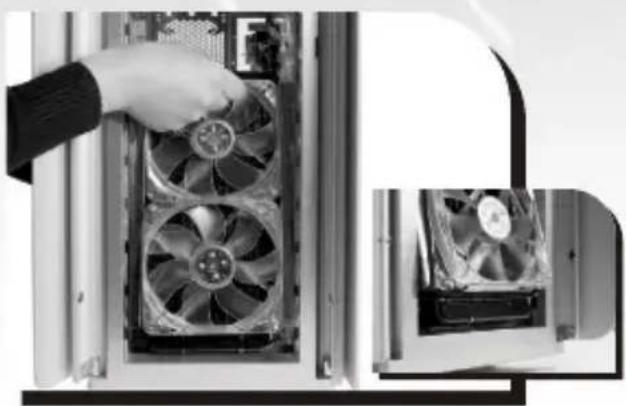
natural_image
Close-up of a hand inserting into a computer drive into a rack, showing fan arrangement (no text or symbols visible)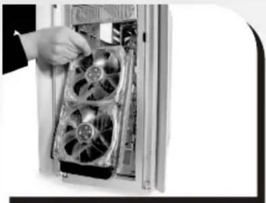
natural_image
Close-up of a hand inserting a multi-free fan into a computer case (no visible text or symbols)↑ Tilt up-ward to remove the HDD cage.
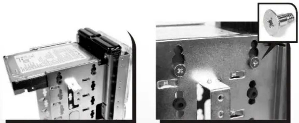
natural_image
Close-up of a mechanical device with mounting holes and a close-up inset showing a metallic component (no visible text or symbols)Place HDD into the cage and secure the HDD by screws.
NOTE:
We strongly recommend you to connect the water tube (see P.41) at this stage then install the HDD cage back to the chassis.
natural_image
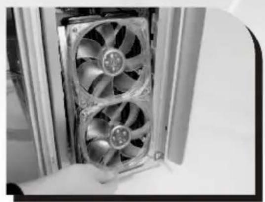
Close-up of a computer tower with two fans, showing internal blades and a hand holding the fan (no text or symbols visible)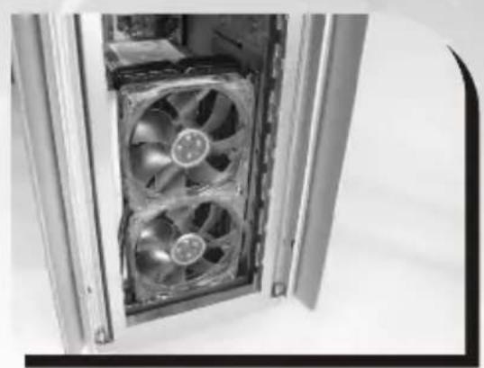
natural_image
Close-up of a computer tower with multiple CPU fans inside the door (no visible text or symbols)↑ Tilt down-ward to put back the radiator
natural_image
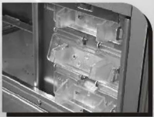
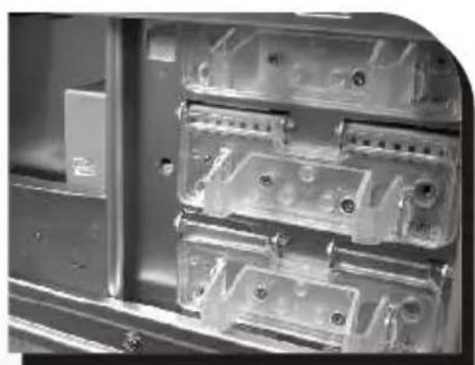
Interior view of an electronic device casing with multiple transparent plastic enclosures (no visible text or symbols)Squeeze and push in-ward the tool-free clips. Place back the drive bay covers.
natural_image
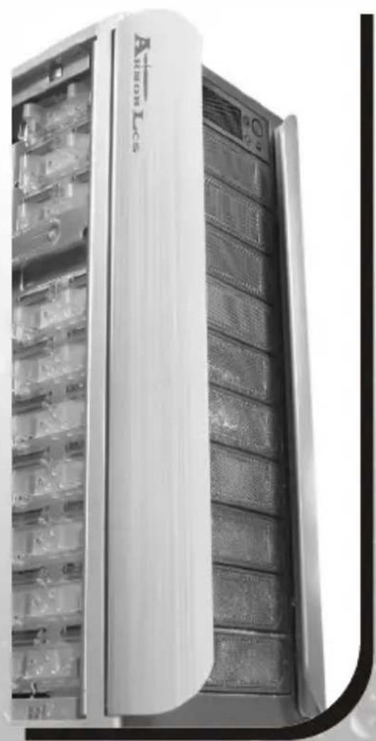
Exterior view of a server rack unit with visible internal components and ventilation grilles (no text or symbols)2.5 Installing 3.5" Device to Drive Tray With Power Button
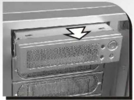
natural_image
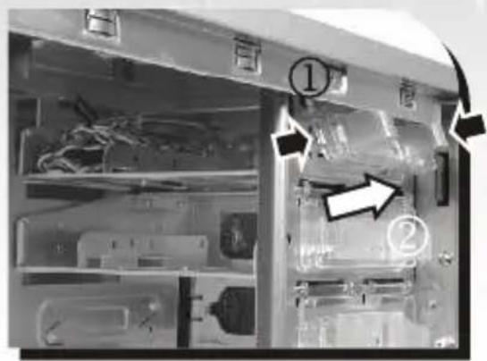
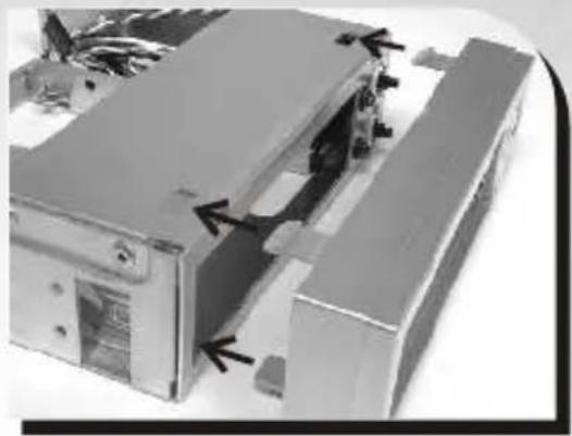
Close-up of a computer monitor rear panel with a black arrow pointing to the front panel (no text or symbols visible)Squeeze and pull out-ward the tool-free clip securing the drive tray with power button. Remove and slide drive bay out-ward to remove.
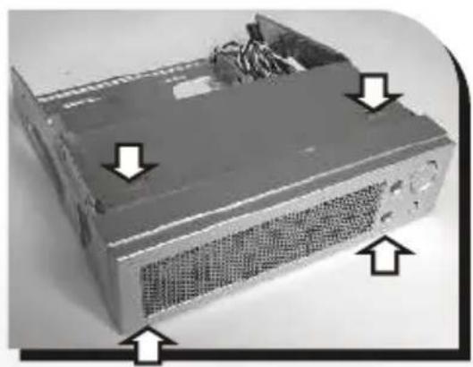
natural_image
Close-up of a computer drive chassis with visible ventilation slots and wiring (no text or symbols)← Squeeze both top and bottom portion of drive tray cover picture to the left to remove cover.
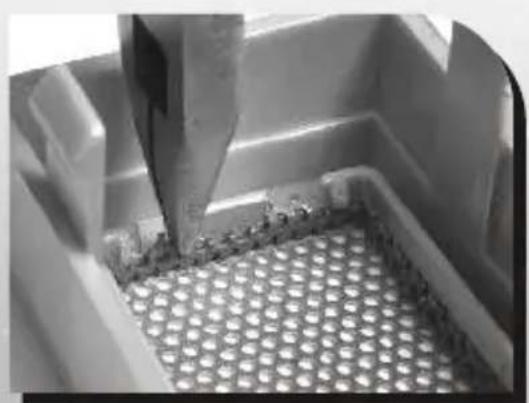
natural_image
Close-up of a metallic component with a pointed tool inserted, showing a perforated surface (no text or symbols visible)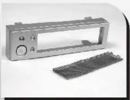
natural_image
Exterior view of a metallic electrical enclosure with a grid-patterned base (no text or symbols visible)↑ Remove mesh from cover
natural_image
3D mechanical assembly diagram showing internal components with arrows indicating movement (no text or symbols)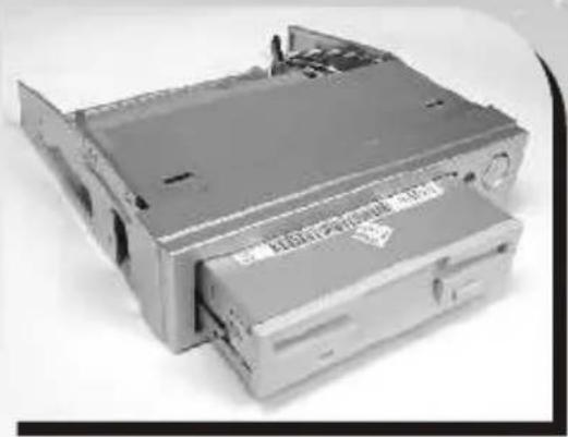
natural_image
Exterior view of a computer drive chassis (no visible text or symbols)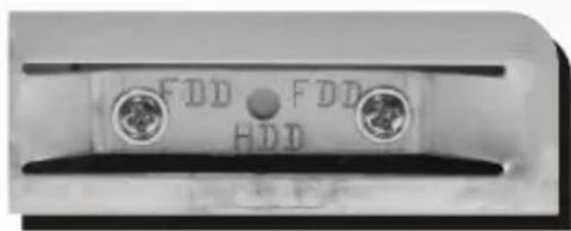
natural_image
Close-up of a mechanical component with two circular ports and a central dot labeled 'FDD', no readable text or symbols beyond the label.Place cover back to drive tray to its original position. Insert 3.25" device and secure device with screw.
natural_image
Close-up of a computer tower case with a black arrow pointing to the front panel (no visible text or symbols)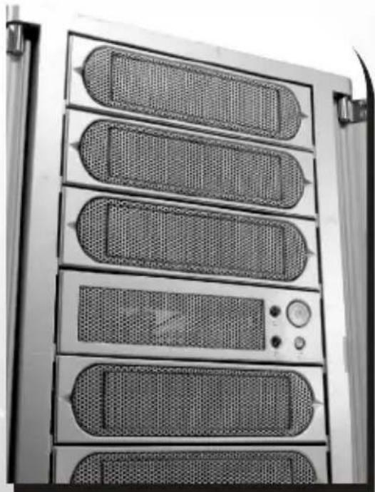
natural_image
Front view of a server rack unit with multiple rack-mounted units and ventilation grilles (no visible text or labels)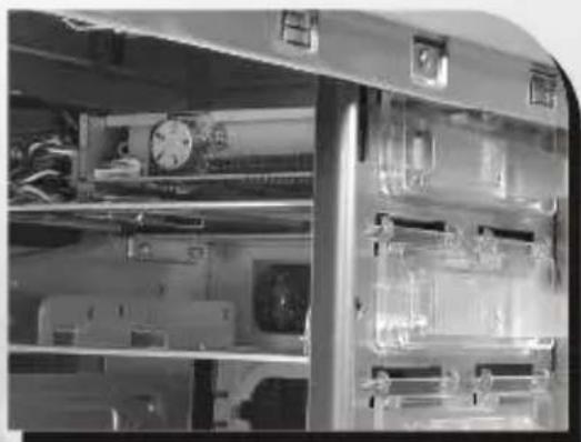
natural_image
Interior view of a laboratory or laboratory equipment cabinet with glass shelves and internal components (no visible text or symbols)Drive tray with Power Button can be placed at any drive bay desired.
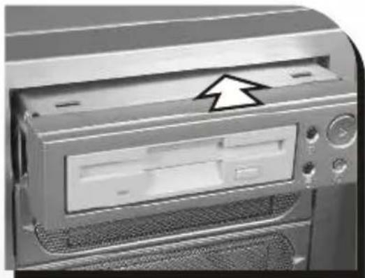
Insert back the device tray pictured above. Squeeze and push in-ward the tool free clip to secure the device tray
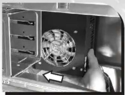
2.6 Installing Power Supply
natural_image
Close-up of a hand inserting a fan into an open device, showing internal components and a black arrow pointing to the fan (no text or symbols visible)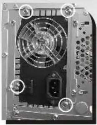
natural_image
Close-up of a computer drive casing showing fan, ports, and internal components (no visible text or symbols)Install power supply unit as shown in pictures
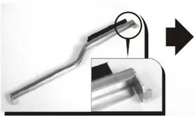
natural_image
Close-up of a metallic tool handle with a magnified inset showing detail (no text or symbols)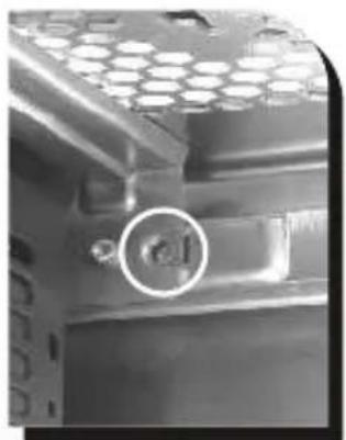
natural_image
Close-up of a metallic mechanical component with hexagonal lattice pattern and a circular annotation (no readable text or symbols)↑ Locate the hook of PSU supporter on the hole which is circled in photo above
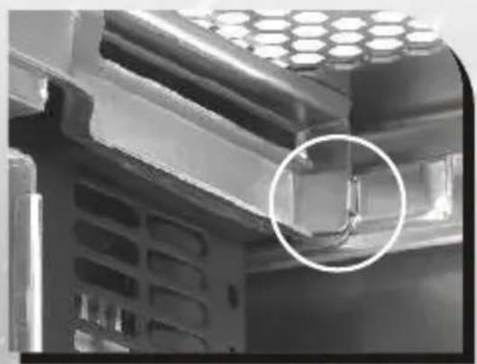
natural_image
Close-up of a mechanical component with hexagonal top and internal structure, circled in white (no visible text or symbols)← Swing the supporter to its proper position as shown in photo above
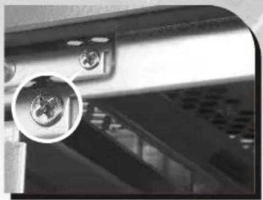
natural_image
Close-up of a mechanical component with a magnified inset showing a circular detail (no visible text or symbols)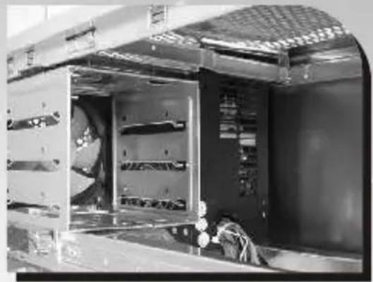
natural_image
Interior view of an industrial machine with visible cooling fans and internal components (no text or symbols)↑ Secure the supporter with screw
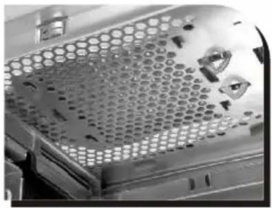
2.7 Installing the fan on top of the case
natural_image
Close-up of a perforated metal panel with hexagonal patterns and mounting holes (no text or symbols visible)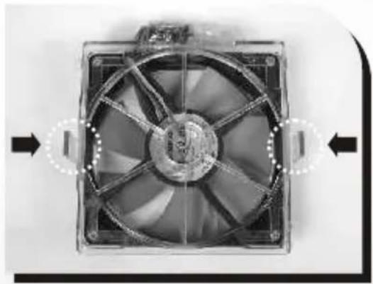
natural_image
Close-up of a computer fan with visible blades and central hub, no text or symbols present↑ Press-in 2 clips on the side of fan
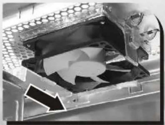
natural_image
Close-up of a mechanical fan component with a highlighted arrow indicating motion (no text or symbols visible)Align all clips with mounting holes, then push-in the fan against case body to secure it.
natural_image
Close-up of a transparent container with a honeycomb-like structure and an arrow pointing to it, no visible text or symbols.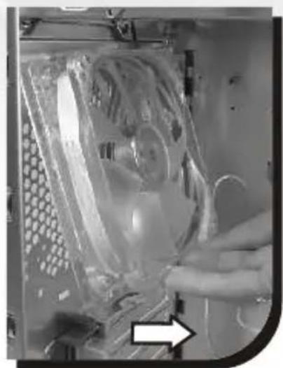
natural_image
Close-up of a hand inserting a plastic device into a rack, with an arrow pointing to the component (no visible text or symbols)↑ Push fan clip up-ward to loose fan, then remove fan holder from inside
9 cm rear fan
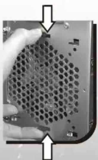
natural_image
Close-up of a hand holding a hexagonal grid device with no visible text or symbols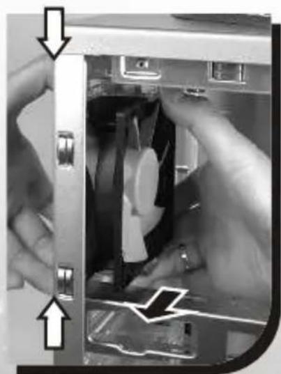
natural_image
Close-up of hands operating a computer case with a device inside (no visible text or symbols)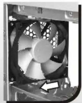
natural_image
Close-up of a computer CPU fan with visible cooling effect and mechanical components (no text or symbols)To remove fan & fan holder by press-in clips then pull both from inside. Please see above picture
2.9 Air Cooling System
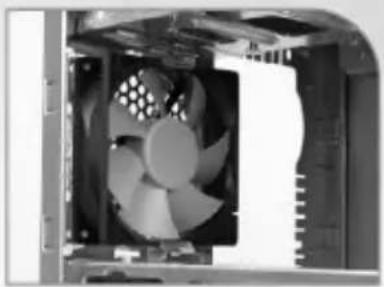
natural_image
Interior view of a computer tower showing a CPU fan with visible blades and ventilation slots (no text or symbols)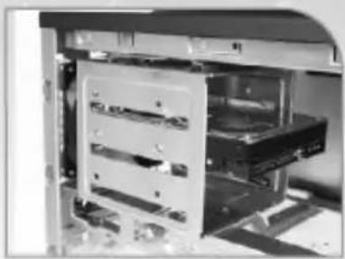
natural_image
Interior view of a computer drive bay with multiple drive bays and a central rack (no visible text or labels)-90 x 90 x 25mm, 1800rpm, 19dBA
-Rear HDD cooling
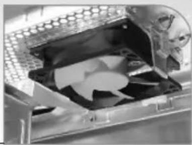
natural_image
Close-up of a mechanical component with a metallic housing and internal structure (no visible text or symbols)-Top (Exhaust) :
90 x 90 x 25mm,
1800rpm, 19dBA
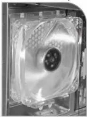
natural_image
Close-up of a CPU fan with visible internal structure and mounting bracket (no text or symbols)-Rear (Exhaust) :
120 x 120 x25 mm Blue LED fan, 1300rpm
natural_image
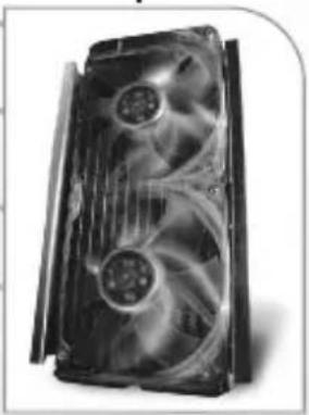
Close-up of a black CPU fan with visible cooling effect and ventilation slots (no text or symbols)-Front (intake) :
Dual 120x120x25 mm
Blue LED fan,
1300rpm, 17dBA
natural_image
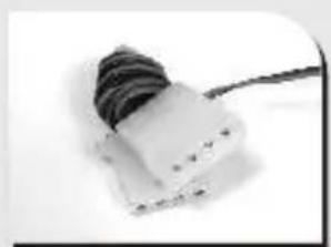
Close-up of a small electronic component with a black cable and a white base (no visible text or symbols)4-pin connector: connect to PSU
natural_image
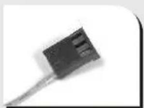
Close-up of a black electronic component with a coiled cable (no visible text or symbols)3-pin signal connector: connect to M/B
2.10 BTX Upgraded Kits
natural_image
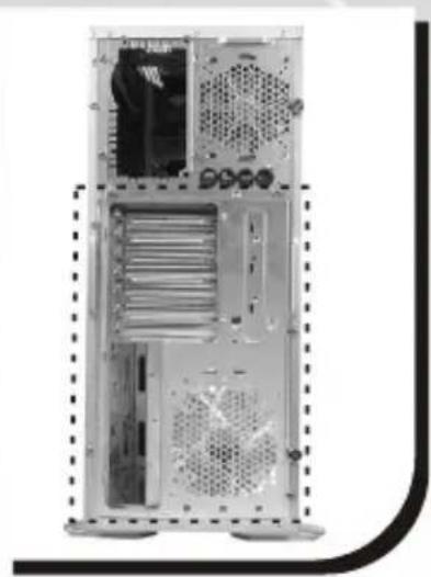
Interior view of a desktop computer tower showing drive bays and ventilation slots (no text or labels visible)← BTX rear plate
natural_image
Metallic mechanical component with cutouts and mounting holes (no visible text or symbols)← BTX SRM (Supported Retention Module)
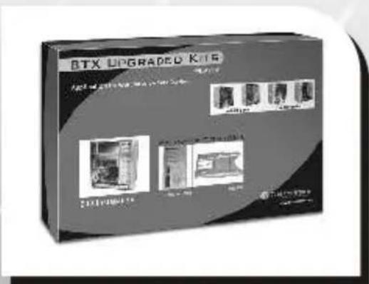
BTX upgraded kit box (P/N:A9358)
2.11 PCI slot tool-free function operation
Open the plastic clip then take off the PCI bracket as follow.
natural_image
Interior view of a refrigerator or oven with a stack of rectangular units and a white arrow pointing to a component (no visible text or symbols)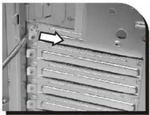
natural_image
Close-up of a computer tower panel with heat sinks and ventilation slots (no text or symbols visible)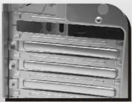
natural_image
Close-up of a computer tower rear panel showing internal rack structure (no visible text or labels)Chapter3 Motherboard & Leads Installation
3.1 Motherboard Installation
Each motherboard has different standoff layout. It is highly suggested that you refer to your motherboard's manual when installing motherboard into the Case. The cases are applicable with Standard ATX and Micro ATX motherboards.
Your motherboard may require a special I/O Panel, which should be included with your motherboard.
Placement Direction:
When installing the motherboard, make sure you follow the direction provided by your motherboard manufacturer. On most standard motherboards, the edge with external ports goes to the rear part of the chassis. It is highly recommended that you install CPU, heat sink and modular components before fixing the motherboard inside the chassis.

This side towards the rear of the chassis
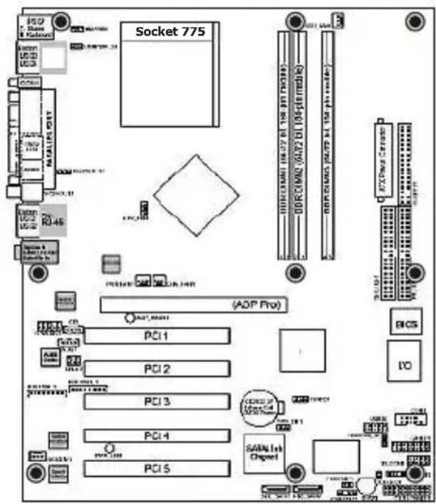
● = the locations of the screw holes. Note these locations and place included standoffs on the chassis first.
Above illustration is a sample of what the motherboard's layout. For more detail screw hole placement, please refer to your motherboard manual.
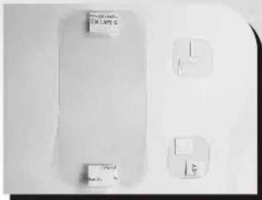
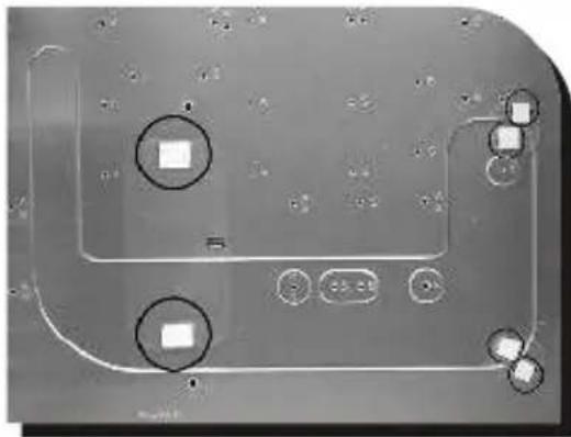
Inside the accessory box, please locate the Mylars (clear plastic films).
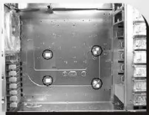
*Note: Due to the unique design of the Armor LCS Chassis, these Mylar tapes are included to prevent ATX motherboards from contacting the chassis.
natural_image
Close-up of a printed circuit board with two circular annotations highlighting square features (no readable text or symbols)Remove the adhesive backing and place the Mylars over each locations as shown.
natural_image
Interior view of a server rack with four circular annotations highlighting specific components (no readable text or symbols)Completed. Please note the Mylar tapes included are transparent. The image here is for reference only.
*Note: When assembling BTX motherboards into the Armor LCS chassis, these Mylar tapes are not necessary.
3.2 Case LED connections
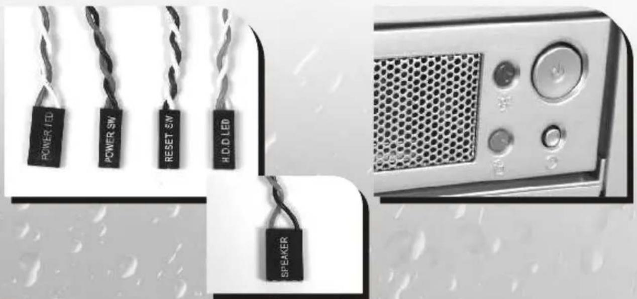
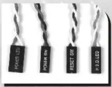
On the front of the case, you can find some LEDs and switch leads (POWER SW*1, POWER LED*1, H.D.D. LED*1, RESET SW*1, SPEAKER*1).
Please consult user manual of your motherboard manufacturer, then connect these leads to the panel header on the motherboard. These leads are usually labeled; if not, please trace them back to the case front to find out their source.
- POWER LED
connects to your M/B at the PLED.
- POWER SW
connects to the PWR connector on the motherboard.
- H.D.D LED
connects to the 2-pin labeled HDD LED connector.
- RESET SW
connects to the RSW connector on the motherboard.
- SPEAKER
connector: find out the 4-pin labeled SPEAKER on the M/B then connect it.
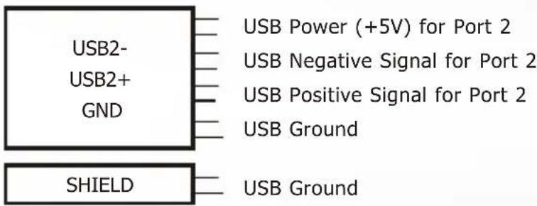
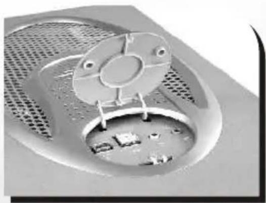
3.3 USB2.0 & IEEE1394 Firewire connection
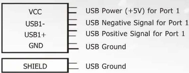
USB connection
Please consult your motherboard manual to find out the section of "USB connection".
USB Function
natural_image
Close-up of a mechanical component with a circular housing and perforated base (no visible text or symbols)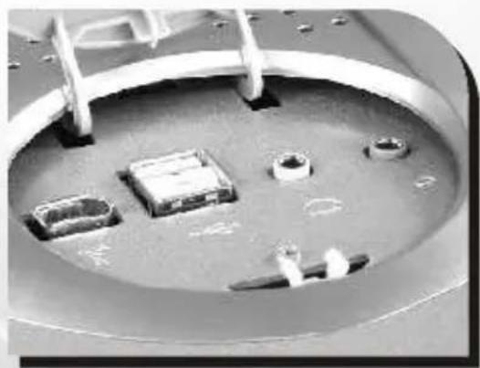
natural_image
Close-up of a mechanical component with multiple circular features and mounting holes (no visible text or symbols)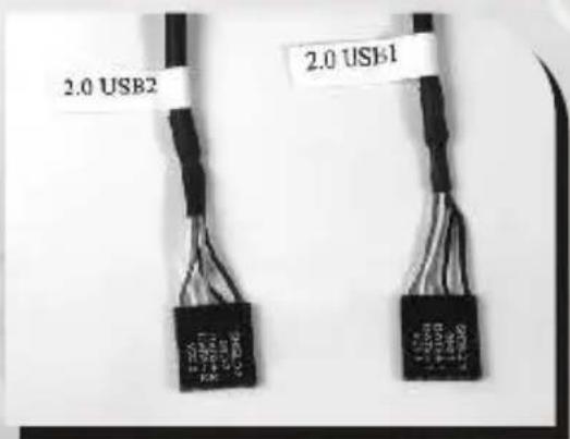
IEEE1394 Firewire connection
Please consult your motherboard manual to find out the section of "IEEE1394 Firewire connection".
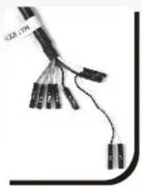
natural_image
Close-up of a black cable with multiple connectors and wires, no visible text or symbolsTPA+ GROUND TPB+ VP
natural_image
Pure electrical circuit lines without any symbols3.4 Audio connections
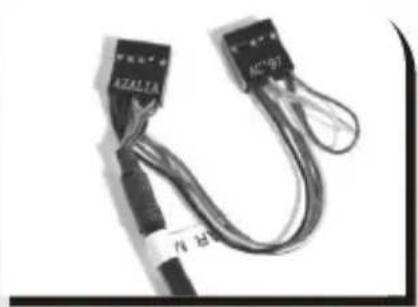
natural_image
Close-up of two connected cable connectors with visible labels (no readable text or symbols)- Please refer to the following illustration of Audio connector and your motherboard user manual.
- Please select the motherboard which used AC'97 or HD Audio (Azalia), (be aware of that your audio supports AC'97 or HD Audio (Azalia)) or it will damage your device(s).
- On some motherboards, the connectors for Audio are not the same as the drawing below. Please check with your motherboard manual before installing.
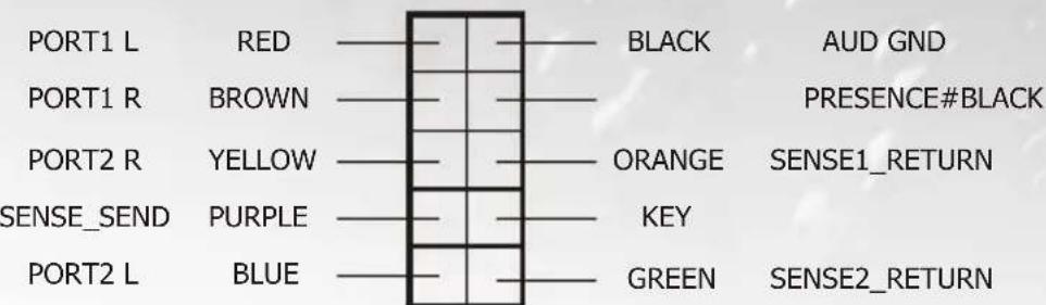
AUDIO AZALIA Function
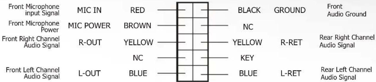
AUDIO AC'97 Function
3.5 Case open alarm function
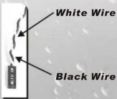
1 To find out the cable with 2pin connector ("Micro SW") from the rear of inside the chassis.
2 To find out the position of Chassis Alarm on your motherboard. (please consult your motherboard manual)
Chapter4 Other
4.1 Purepower™ power supply (optional)
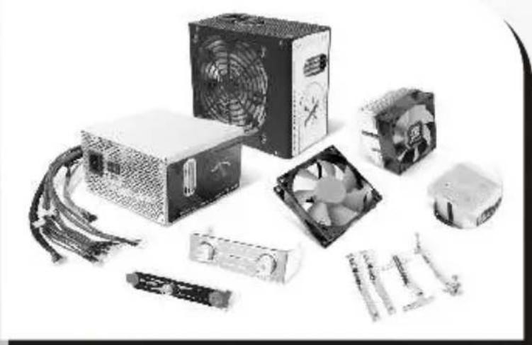
The Thermaltake Silent™ Purepower specification meets Intel Pentium 4 and AMD K7.K8 ; it offers plenty of functions, which mainly include:
1. Automatic Fan Speed Control :
The Silent Purepower ^™ power supply can detect the inside heat and automatically adjust the fan speed to provide adequate airflow.
2.Ultra Silent :
Ball bearing fans with high reliability and super low acoustic noise under all load condition.
The functions can assure the Silent Purepower ^™ meet the balance in noise control and heat exhausted. The Silent Purepower ^™ provides complete protection function as follow:
- Over thermal protection at 100^ C- 105^ C
- Short circuit protection on all output.
- Over voltage protection / Under voltage protection.
- Over current protection.
Besides, Thermaltake enables the quality assurance of the Silent Purepower™: 100% Hi-POT and ATE Function Test, 100% Burn-In and AC Input cycled on/off under high temperature condition. Furthermore, it has been approved by UL, CSA, TUV, VDE, NODIC, CB, FCC, CE, CNS.
natural_image
Collection of electronic circuit board components including a power supply unit, fan, CPU socket, and cooling unit (no visible text or labels)There are three main products of Thermaltake PSU, it is divided into standard, VR and specialty power supply unit. Please refer to http://www.thermaltake.com/purepower/main.htm
5.1 Specification
| Water Block | Dimensions | 78(L)x 60(W) x 23.5(H)mm |
| Material | Copper & Acrylic | |
| 3 pinConnector | ||
| Blue LED LED | ||
| Pump | Ceramic bearingBearing | |
| Flow Rate | 400 L/ hr | |
| DC 12VRated Voltage | ||
| 4 pinConnector | ||
| Blue LED LED | ||
| Noise | 16 dBA | |
| Life time | 80000 hr (MTBF) | |
| 240mm Radiator | Dimensions | 240(H) x 120(W) x28(D)mm |
| Material | Aluminum | |
| Fan Dimension | 120 x 120 mm | |
| Fan Speed | 1300 RPM | |
| Max Air Flow | 54.4 CFM | |
| Noise | 16 ~ 17 dBA | |
| Fan Connector | 2 pin | |
| Liquid Tank | Dimensions | 86(L)x66(W)x110(H)mm |
| 350 c.cCapacity | ||
| Quick Install Connector | For 9.5mm ID(3/8") tube | |
| Tube | Dimensions | 9.5mm ID(3/8") tube |
| Material | Green UV | |
| Coolant | Capacity | 500 c.c |
| Major Material Ingredient | Ethylene Glycol | |
| Application | CPU | AMD all K8 series |
| Intel LGA775 | ||
| Intel BTX platform |
5.2 Components
natural_image
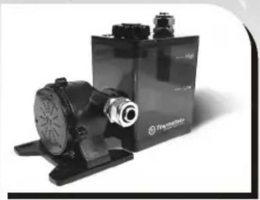
Exterior view of a black industrial engine pump and battery unit (no visible text or symbols)P500 Pump & Liquid tank
natural_image
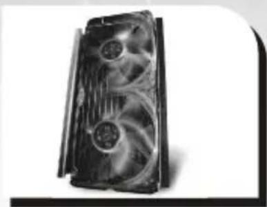
Close-up of a black CPU fan with visible cooling effect and ventilation slots (no text or symbols)120 mm X 240mm Radiator with two 1300RPM 120mm fans
natural_image
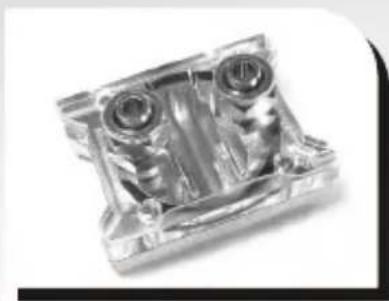
Close-up of a transparent plastic mechanical component with two cylindrical ports and mounting holes (no visible text or symbols)Copper waterblock with blue LED acrylic cover
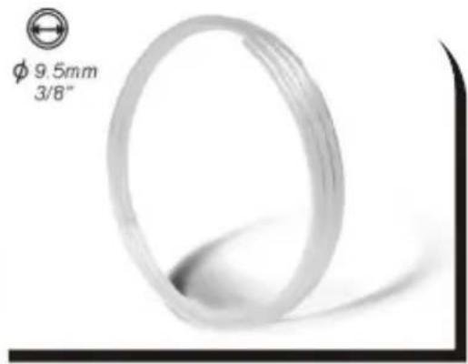
ID 9.5mm(3/8")UV sensitive Water Tube 400cm x 1
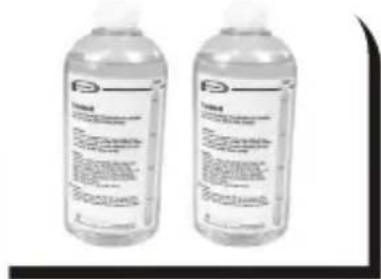
↑ UV sensitive 500 cc Coolant x 2
natural_image
Close-up of a black cable with multiple white connectors (no text or symbols visible)2pin to 4pin cable
natural_image
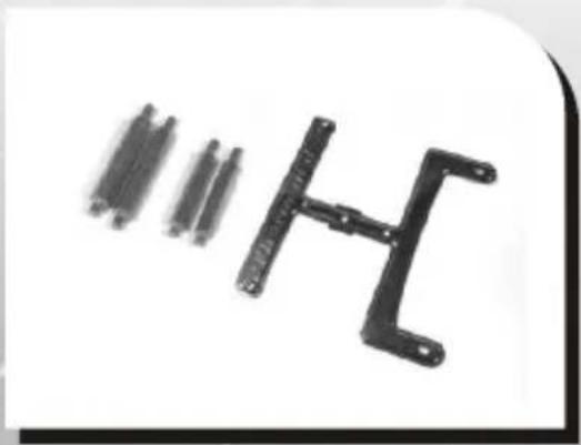
Black metal bracket with multiple cylindrical connectors, no visible text or symbols↑ Clips for BTX motherboard
natural_image
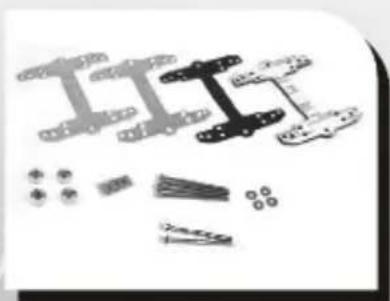
Exploded view diagram of a mechanical assembly (no text or labels)↑ Clips for ATX motherboard
Thermal compound
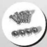
Screws for pump
5.3 Installation steps
In order to ensure convenience and safety, following the installation procedure below is strongly recommended.
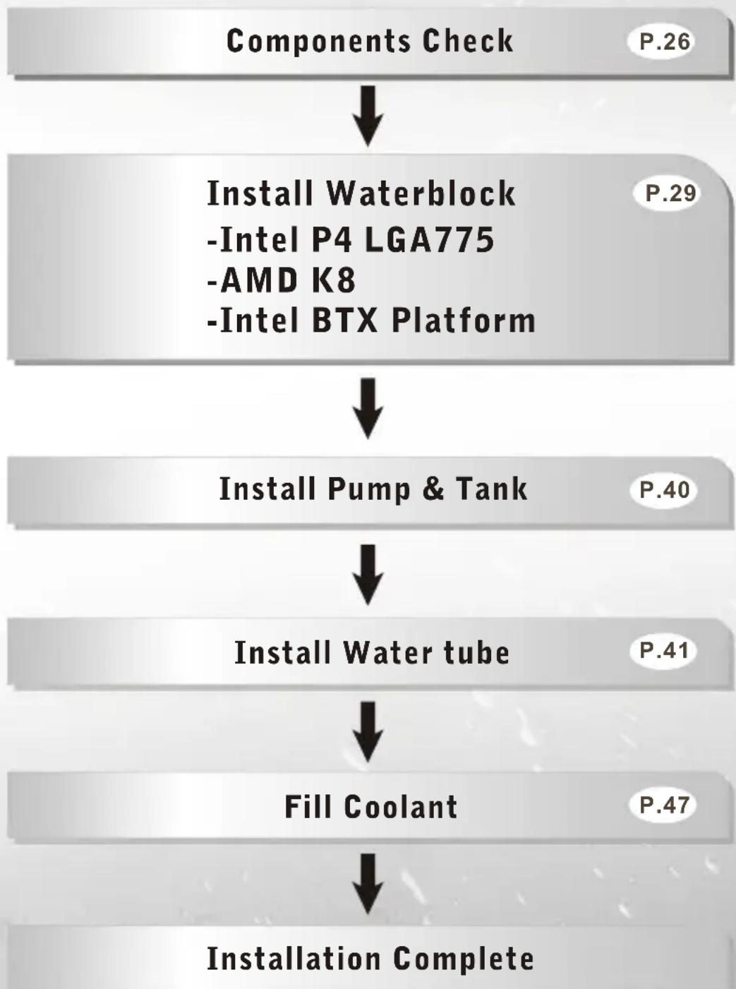
flowchart
graph TD
    A["Components Check"] --> B["Install Waterblock\n-Intel P4 LGA775\n-AMD K8\n-Intel BTX Platform"]
    B --> C["Install Pump & Tank"]
    C --> D["Install Water tube"]
    D --> E["Fill Coolant"]
    E --> F["Installation Complete"]
5.4 Install Waterblock
5.4.1 Clip the Waterblock on CPU (Intel P4 LGA775)
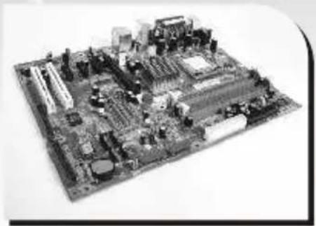
natural_image
Black-and-white photo of a computer motherboard with visible CPU socket, RAM slots, and circuitry (no text or labels)Intel LGA 775
Motherboard
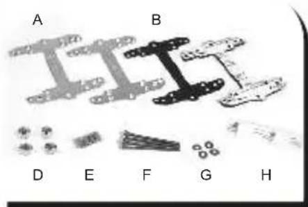
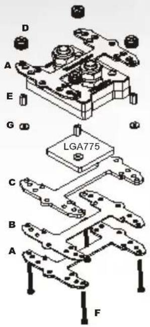
Clips for LGA 775
A. Metal H-type clip
B. Thin insulator
C. Thick insulator
D. Thumb nuts
E. Stand Offs
F. Screws
G. Washers
H. Thermal compound
natural_image
Close-up of hands assembling a black mechanical bracket component (no text or symbols visible)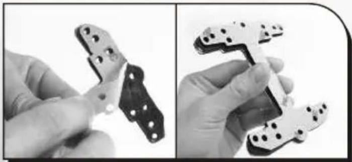
natural_image
Two black-and-white images showing hands holding a mechanical component, no text or symbols visible.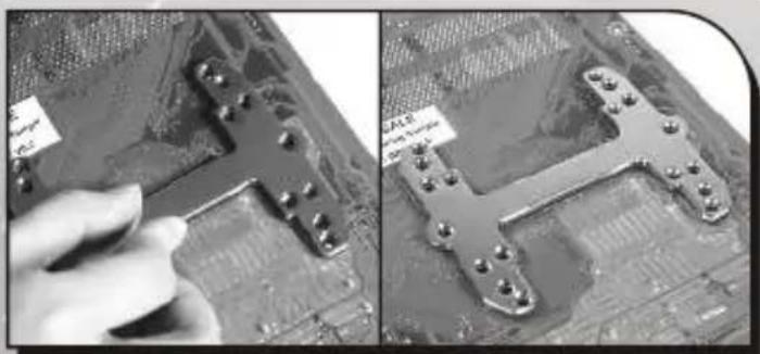
natural_image
Two-panel image showing a hand adjusting a circuit board component, with no visible text or symbols.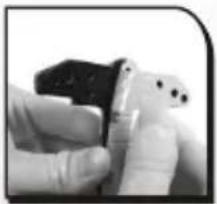
natural_image
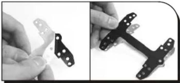
Close-up of a hand holding a small electronic component (no visible text or symbols)Tear off the tape on the back of the thin insulator (B) and place it on the metal H-type clip(A).
Combine the mylar (thin insulator) and the foam (thick insulator) using the adhesive. Stick the metal H-type clip(A) with the insulators (BC). Tear off the protective layer to adhere it onto the motherboard.
Attach H-type clips(including ABC) on the back side of motherboard.
natural_image
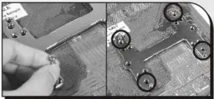
Close-up of a circuit board with labeled components and a hand adjusting a component (no readable text or symbols)Insert the screws (F) into the four holes as shown in the photo.
natural_image
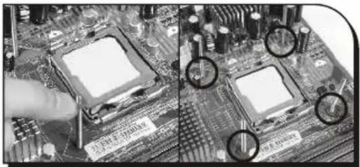
Close-up of a computer motherboard with visible CPU socket and circuit board, showing soldering defects (no text or symbols)Put the washers(G) along the screws to prevent the electric current.
natural_image
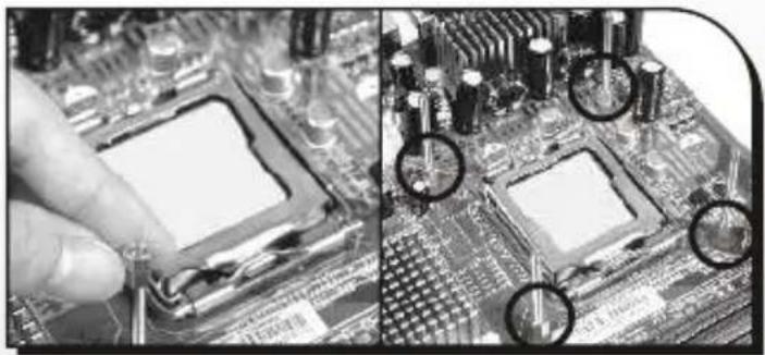
Close-up of a computer motherboard with visible traces and components, no text or symbols presentPut the stand offs(E) along the screws to fix the screws on the motherboard.
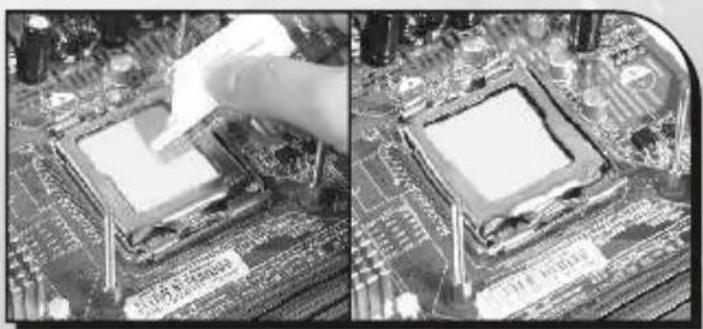
natural_image
Close-up of a computer motherboard with a hand placing a chip onto the CPU socket (no visible text or symbols)Apply a thin layer of grease onto the processor.
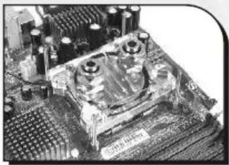
natural_image
Close-up of a computer motherboard with visible CPU socket and circuit board (no text or symbols)← Place the waterblock on the processor.
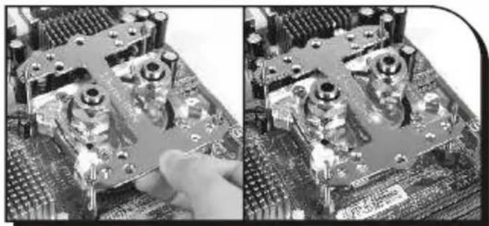
natural_image
Close-up of a computer motherboard showing two views of the chip with visible circuitry and components (no text or symbols)← Put the H-clip on the Waterblock.
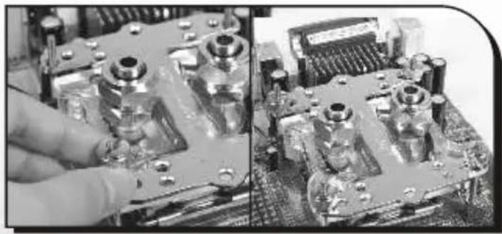
natural_image
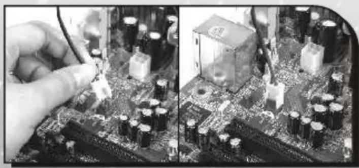
Close-up of a hand adjusting a metal mechanical component, showing internal parts and mounting holes (no visible text or symbols)Tighten the Thumb nuts(D) to the screws as shown to fix the waterblock on motherboard.
natural_image
Close-up of a hand inserting a component into a motherboard, showing circuit board and battery components (no text or symbols visible)Plug the LED power into the 3-pin power connector on the motherboard.
5.4.2 Clip the Waterblock on CPU (AMD K8)
A. Metal back plate
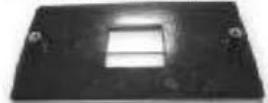
B. Plastic back plate
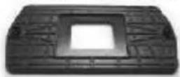

Check Your Back Plate!
If your Motherboard includes:
-Metal back plate-
higher mounting holes, the installation is as same as the K8 Standard installation(A).
-Plastic back plate (the ASUS
motherboards, for example)-
lower mounting holes, the installation is as following(B).
(A) Install by back plate for motherboard (Standard installation)
natural_image
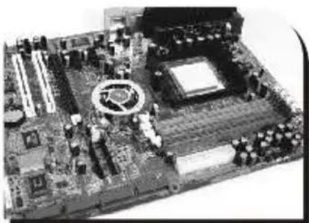
Close-up of a computer motherboard with CPU socket and surrounding circuitry (no visible text or labels)AMD K8
Motherboard
natural_image
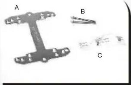
Three labeled mechanical components (A, B, C) with no visible text or symbols on the parts themselves.Clips for K8
A. Metal H-type clip
B. Screws
C. Thermal compound
natural_image
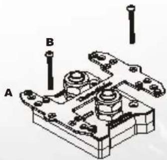
Technical illustration of a mechanical assembly with labeled parts A and B (no text or symbols beyond labels)
natural_image
Close-up of a computer motherboard showing two views: top view with CPU socket and circuit board, bottom view with mechanical components (no visible text or symbols)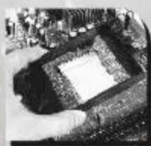
natural_image
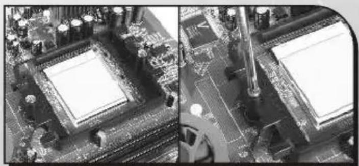
Aerial view of an ancient stone structure with a central square, surrounded by earth and small figures (no visible text or symbols)Remove the retention frame from motherboard.
natural_image
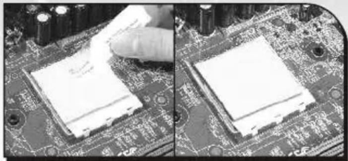
Close-up of a computer motherboard with a hand inserting a component (no visible text or symbols)Apply a thin layer of grease onto the processor.
natural_image
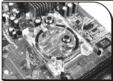
Close-up of a computer motherboard with visible circuitry and components (no text or symbols)← Place the waterblock on the processor.
natural_image
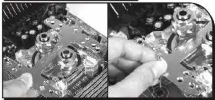
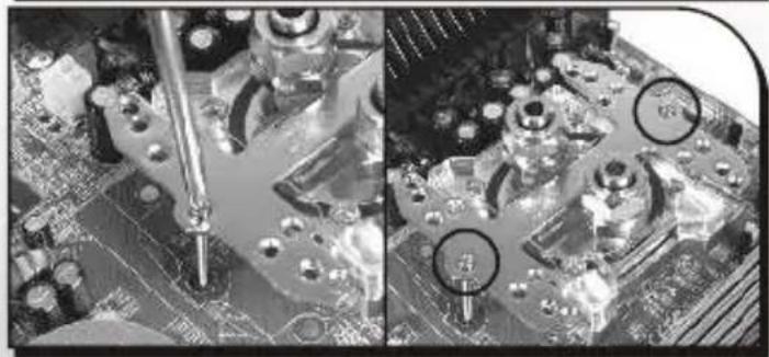
Close-up of hands installing or adjusting a circuit board component (no visible text or symbols)Put the H-clip on the Waterblock and insert screws(B) as shown in the photo.
natural_image
Close-up of a computer motherboard with visible circuitry and soldering tools (no text or symbols)Secure the waterblock onto the motherboard.
natural_image
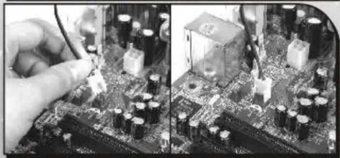
Close-up of hands connecting a component to a circuit board with visible battery and CPU socket (no text or symbols)Plug the LED power into the 3-pin power connector on the motherboard.
(B) Install by clips bundled in package
natural_image
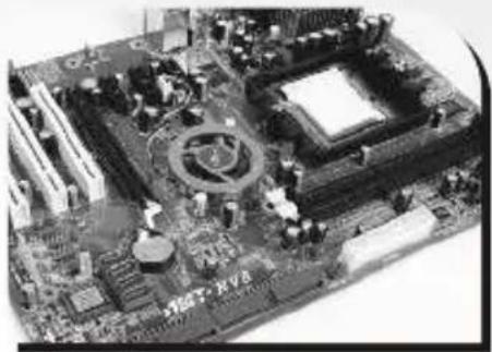
Close-up of a computer motherboard with CPU socket and circuit board (no visible text or symbols)AMD K8
Motherboard
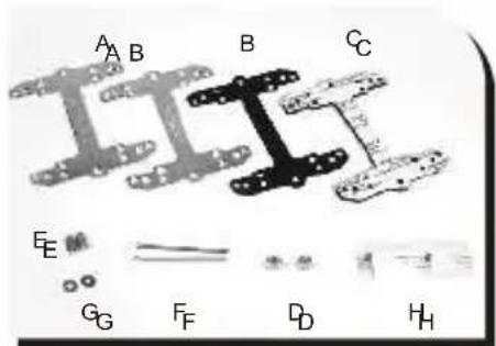
A. Metal H-type clip
B. Thin insulator
C. Thick insulator
D. Thumb nuts
E. Stand Offs
F. Screws
G. Washers
H. Thermal compound
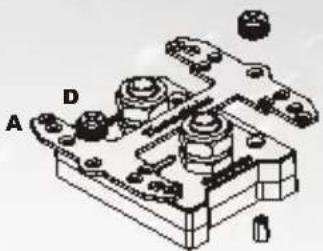
natural_image
Technical illustration of a mechanical assembly with labeled components A and D (no text or symbols beyond labels)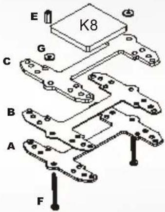
natural_image
Close-up of a computer motherboard with visible CPU socket and circuit board (no text or symbols)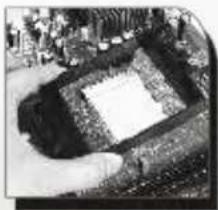
natural_image
Aerial view of a square excavation site surrounded by earth and vegetation, with no visible text or symbols.
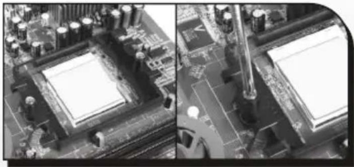
Remove the Retention
Module from the motherboard.
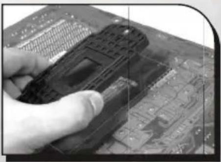
natural_image
Close-up of a hand holding a black handheld device over a circuit board (no visible text or symbols)
Remove the back plate on
back side of motherboard.
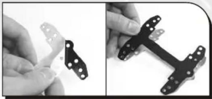
natural_image
Two black mechanical components with white holes, shown from different angles (no text or symbols visible)Tear off the tape on the back of the thin insulator (B) and place it on the metal H-type clip(A).
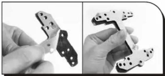
natural_image
Two black-and-white photos showing hands assembling a mechanical component, no text or symbols visible.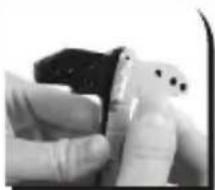
natural_image
Close-up of a hand holding a small black object with dots, possibly a device or tool (no visible text or symbols)Combine the mylar (thin insulator) and the foam (thick insulator) using the adhesive. Stick the metal H-type clip(A) with the insulators (BC). Tear off the protective layer to adhere it onto the motherboard.
natural_image
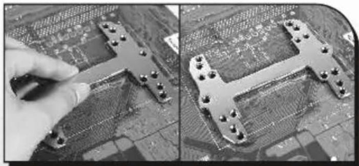
Close-up of a hand adjusting a metal T-shaped electronic circuit board (no visible text or symbols)Attach H-type clips(including ABC) on the back side of motherboard.
natural_image
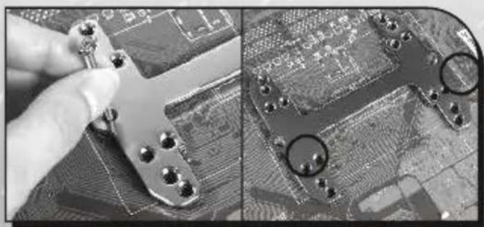
Close-up of a hand holding a metal component next to a printed circuit board (no visible text or symbols)Insert the screws(F) into the two holes as shown in the photo.
natural_image
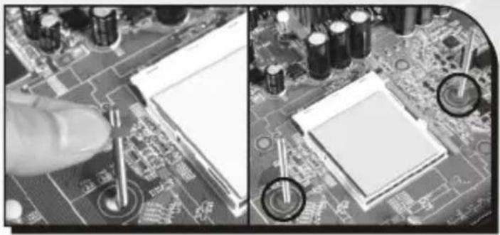
Close-up of a computer motherboard with visible circuitry and components, no text or symbols presentPut the washer(G) along the screws to prevent the electric current.
natural_image
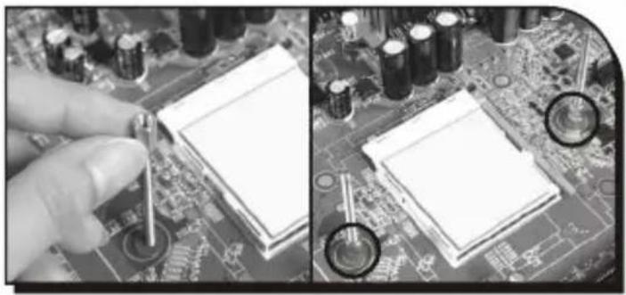
Close-up of hands adjusting a circuit board with a tool, showing two views of components (no text or symbols visible)Put the stand offs(E) along the screws to fix the screws on the motherboard.
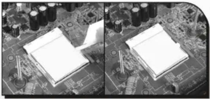
natural_image
Two-panel black-and-white photo showing a computer motherboard with visible circuitry and components (no text or symbols)Apply a thin layer of grease onto the processor.
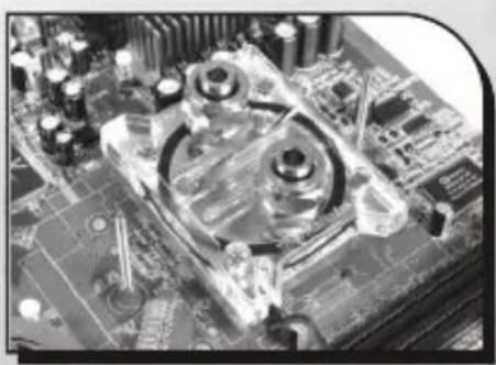
natural_image
Close-up of a computer motherboard with visible CPU socket and circuit board (no text or symbols)← Place the waterblock on the processor.
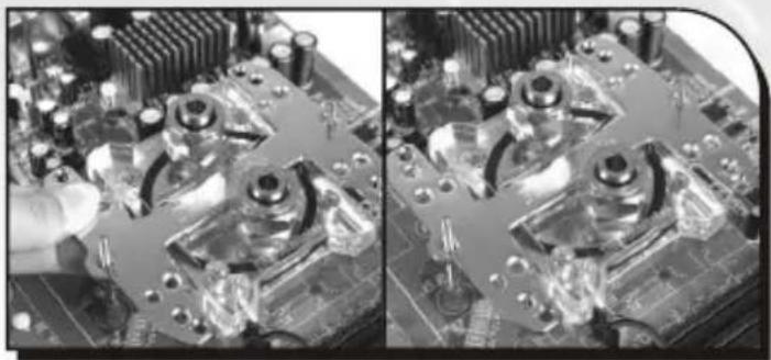
natural_image
Close-up of a computer motherboard with visible circuit board and mechanical components (no text or symbols)← Put the H-clip on the Waterblock.
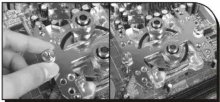
natural_image
Close-up of hands adjusting a metal component on a computer motherboard (no visible text or symbols)Tighten the thumb nuts(D) to the screws as shown to fix the waterblock on motherboard.
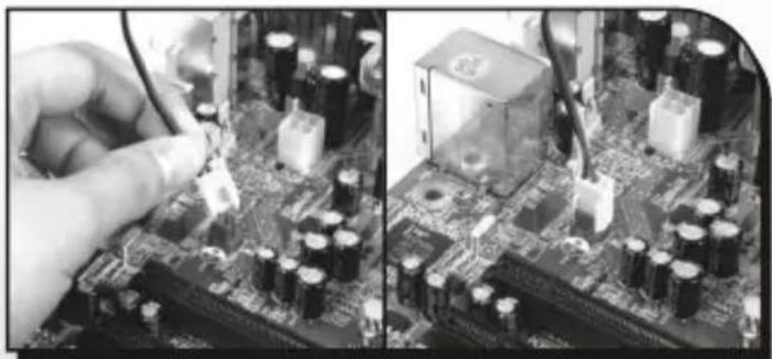
natural_image
Close-up of hands installing components on a circuit board, showing battery and resistor assembly (no visible text or symbols)Plug the LED power into the 3-pin power connector on the motherboard.
5.4.3 Clip the Waterblock on CPU (Intel BTX Platform)
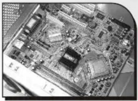
natural_image
Close-up of a computer motherboard with visible circuitry and slots (no text or symbols)Intel LGA 775 BTX Motherboard
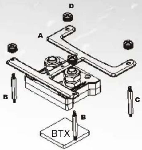
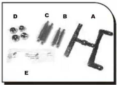
A. Metal H-type clip
B. 40mm Stand Offs
C. 47.5mm Stand Offs
D. Thumb nuts
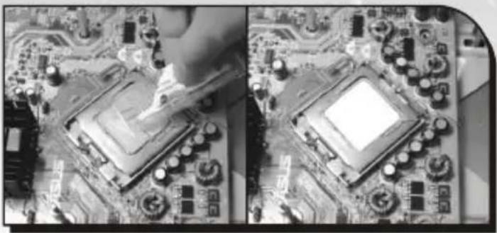
E. Thermal compound
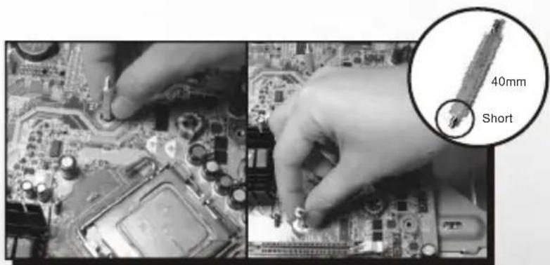
Screws the 40mm stand offs (B) on the Motherboard.
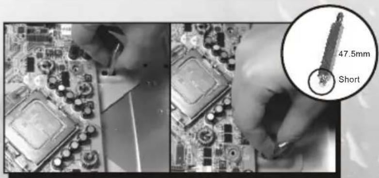
Screws the 47.5mm stand offs (C) on the BTX SRM of case as shown.
natural_image
Close-up of a computer motherboard with visible CPU socket and circuit board (no text or symbols)Apply a thin layer of grease onto the processor.
natural_image
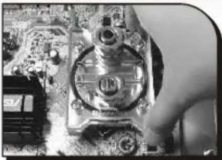
Close-up of a hand adjusting a CPU socket on a motherboard (no visible text or symbols)← Place the waterblock on the processor.
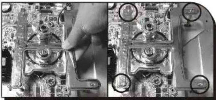
natural_image
Close-up of a hand adjusting a circuit board component, showing mounting holes and wiring (no text or symbols visible)Put the H-clip on the Waterblock.
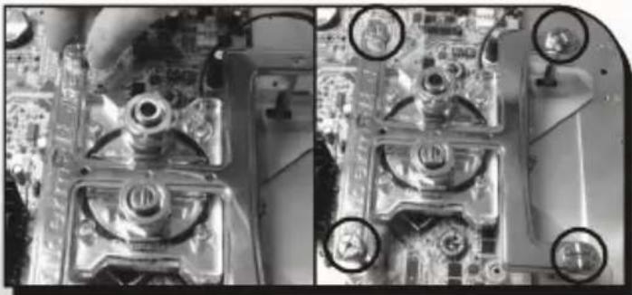
natural_image
Close-up of a computer motherboard showing circuit board and screw holes (no visible text or symbols)Tighten the thumb nuts(D) to the stand offs as shown to fix the waterblock on motherboard.
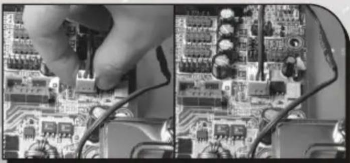
natural_image
Close-up of a hand using a power cord to clean electronic circuit boards (no visible text or symbols)Plug the LED power into the 3-pin power connector on the motherboard.
5.5 Install Pump & Tank
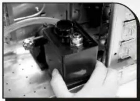
If there are mounting holes on the bottom of your case. You may proceed with the following steps to install the pump.
natural_image
Close-up of a gloved hand holding a small black electronic device with a metallic lens (no visible text or symbols)Finding the mounting holes to fit the stand of pump.
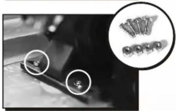
natural_image
Close-up of mechanical components with circular annotations highlighting specific parts (no readable text or symbols)Insert the screws through the holes of the stand as shown. Then, tighten the nuts to secure the pump.
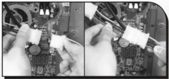
natural_image
Close-up of hands installing cable on a computer motherboard (no visible text or symbols)Connect the 4-pin connector of pump to power supply.
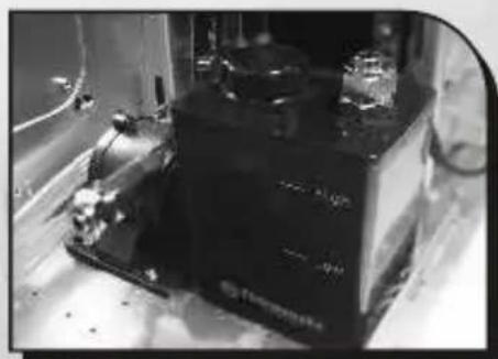
natural_image
Black-and-white photo of a mechanical device with no visible text or symbolsInstallation complete.
5.6 Install Water tube
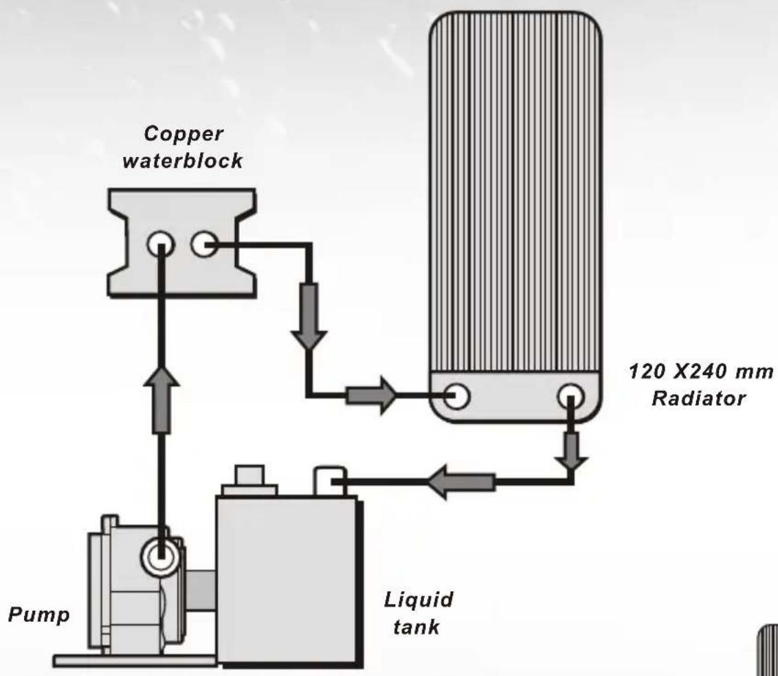
flowchart
graph TD
    A["Pump"] --> B["Copper waterblock"]
    B --> C["120 X240 mm Radiator"]
    C --> D["Liquid tank"]
    D --> E["Return Line"]
    style A fill:#f9f,stroke:#333
    style B fill:#ccf,stroke:#333
    style C fill:#cfc,stroke:#333
    style D fill:#fcc,stroke:#333
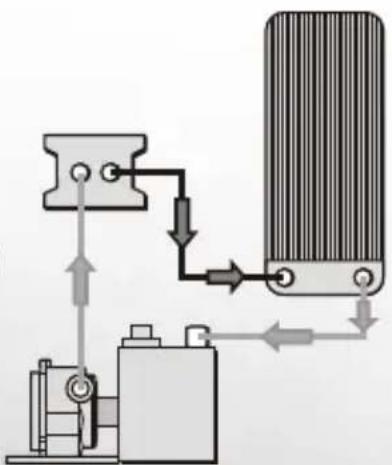
Connect Waterblock to Radiator
natural_image
Pure mechanical diagram showing fluid flow through a heat exchanger and pump (no text or symbols)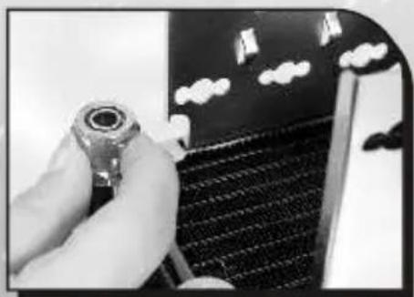
natural_image
Close-up of a hand adjusting a small mechanical component on a guitar fretboard (no visible text or symbols)
Unscrew the nut of 24cm radiator.
natural_image
Black-and-white photo of a futuristic spacecraft with cloud patterns and a small satellite (no visible text or symbols)
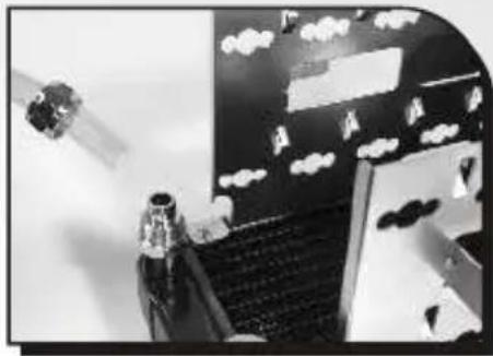
Insert the tube through the nut.
natural_image
Black-and-white photo of a robotic arm interacting with a digital display board (no visible text or symbols)
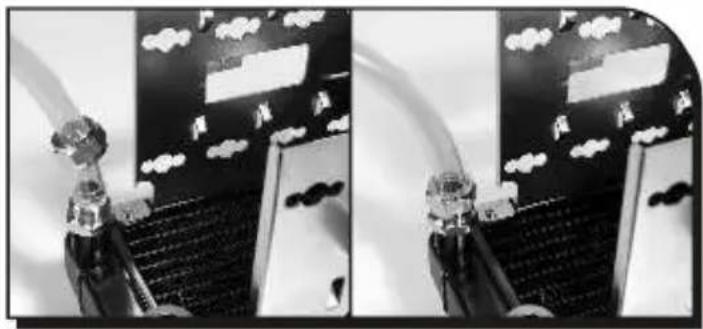
Tighten the nut on 24cm radiator.
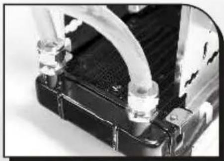
natural_image
Close-up of a mechanical component with coiled tubing and connectors (no visible text or symbols)
Repeat the installation steps for the other side vn on photo.
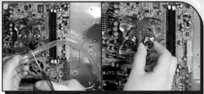
natural_image
Close-up of hands working on a computer motherboard with visible circuitry and wiring (no text or symbols)Please measure and cut the tube, then unscrew the nut of waterblock.
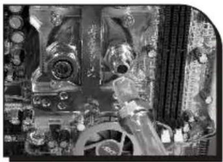
natural_image
Interior view of a vintage computer room with monitor, keyboard, and monitor unit (no visible text or symbols)Insert a tube through the nut of waterblock.
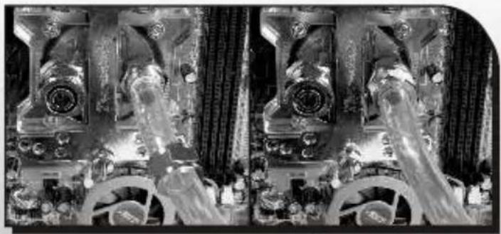
natural_image
Black-and-white 3D-rendered interior scene showing a vintage camera with visible lens and screen, surrounded by curtains and decorative elements (no text or symbols)Tighten the nut on the waterblock.
Connect Radiator to Tank
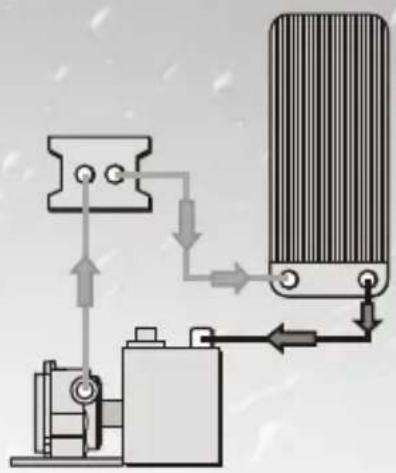
natural_image
Pure mechanical diagram showing fluid flow through a valve and pump assembly (no text or symbols)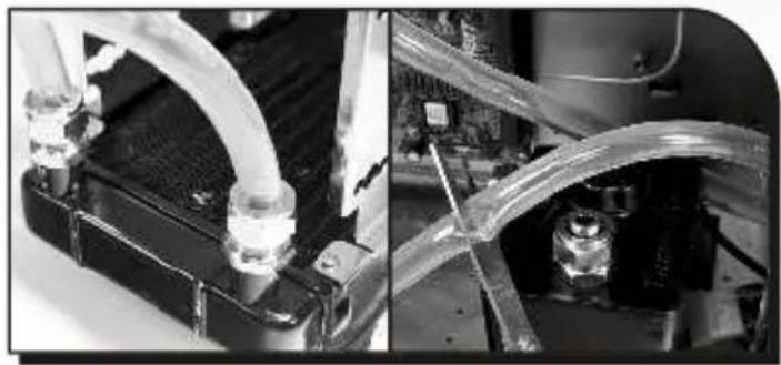
natural_image
Close-up of mechanical components with transparent tubing and connectors, no visible text or symbolsSecure the tube and the nut on 24cm radiator. Please measure and cut the tube, then unscrew the nut of tank.
natural_image
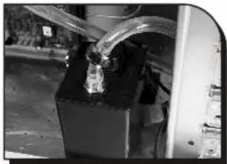
Close-up of a mechanical component with hoses and a rectangular base, no visible text or symbolsInsert the tube through the nut.
natural_image
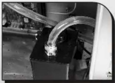
Close-up of a transparent cylindrical component mounted on a black base, with no visible text or symbols.Tighten the nut as shown.
Connect Pump to Waterblock
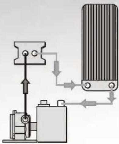
natural_image
Diagram of a mechanical or electrical system with a motor, battery, and heat exchanger (no text or symbols)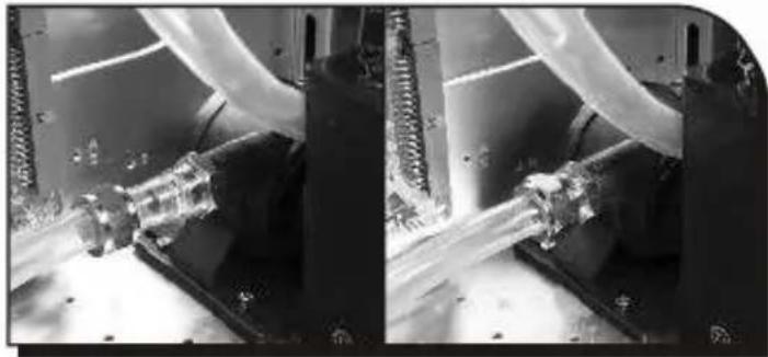
natural_image
Close-up of mechanical components with curved and rectangular features, no visible text or symbolsUnscrew the nut of pump and insert a new tube through the nut. Then tighten it.
natural_image
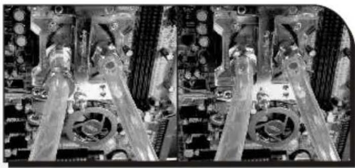
Close-up of a computer motherboard with visible CPU socket and circuit board (no text or symbols)← Unscrew the nut of waterblock and insert the tube from pump through the nut. Then tighten it.
natural_image
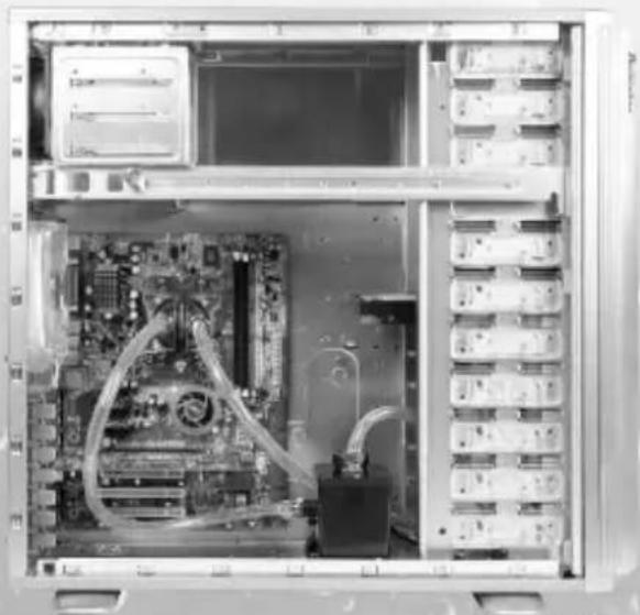
Interior view of a computer tower case showing CPU socket, motherboard, and drive bays (no visible text or labels)← Installation complete.
5.7 Connect the Front Fan to Power Supply
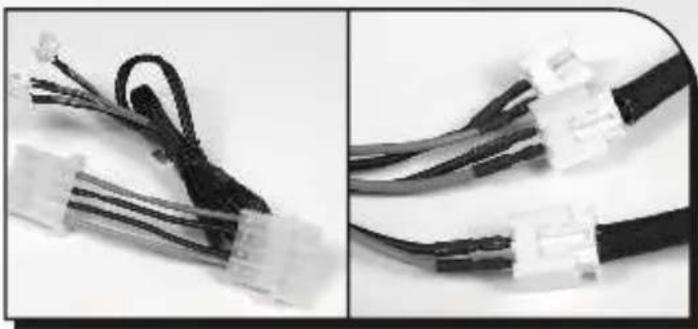
natural_image
Close-up of two black cable connectors with white connectors, shown from different angles (no text or symbols visible)Find the included 2-pin to 4-pin cable. Then, connect the front 120mm fans to the 2-pin connector as shown.
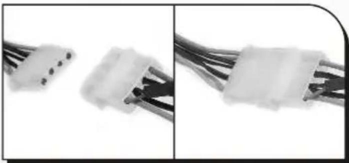
natural_image
Close-up of two white electronic connectors with black wires, shown from side and top views (no text or symbols visible)Connect the 4-pin connector to power supply unit.
5.8 Fill Coolant

natural_image
Close-up of hands adjusting a transparent plastic car hood and valve (no visible text or symbols)Open the cover of liquid tank, and fill the tank up with coolant.
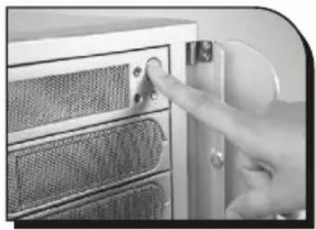
natural_image
Close-up of a hand pressing a button on a server rack (no visible text or symbols)← Turn on the PC power switch.
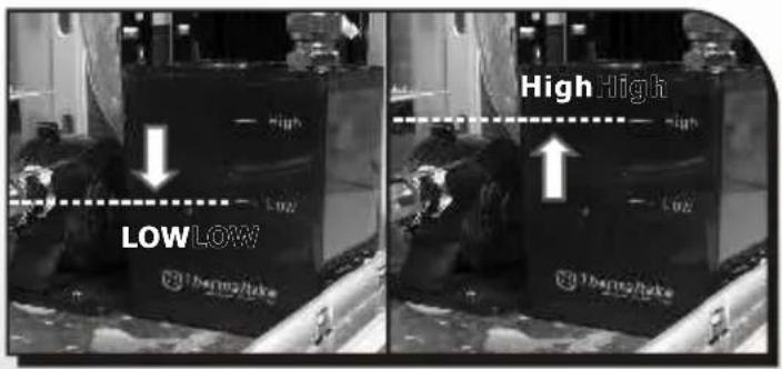
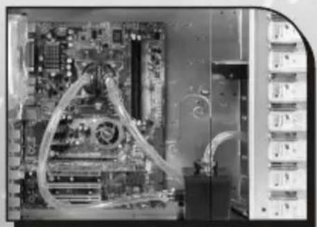
Liquid level will decrease when you power on the system, please keep filling coolant until the tank is filled up.
natural_image
Interior view of a computer motherboard showing CPU socket, RAM slots, and drive bays (no visible text or labels)Please make sure liquid is flowing continuously and smoothly within the tube.
natural_image
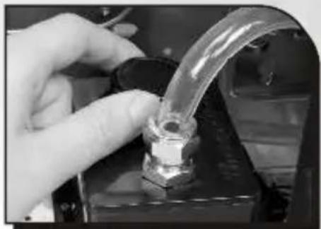
Close-up of a hand adjusting a transparent glass tubing with a black handle (no text or symbols visible)
Close the cover of liquid tank.
natural_image
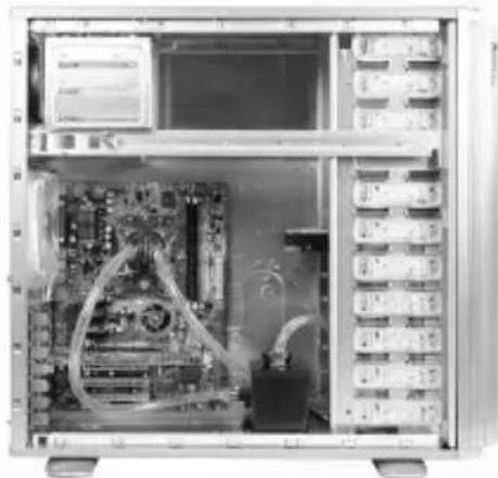
Interior view of a computer tower case showing CPU socket, RAM slots, and server racks (no visible text or labels)
Installation complete.
natural_image
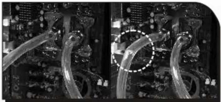
Close-up of electronic circuit board components with visible traces and wiring (no text or symbols)


Note:
- Please make sure there is no air inside the tube when you first time power on the system.
- If there are bubbles within the tube when operating. You may tap the tubes a few times to remove the bubbles.
- Please make sure the water tube is not bending when close the side panel.
5.9 Q & A
Q: When do I have to refill the coolant?
A :For better performance, we strongly recommend you to check the liquid per six month. If the liquid level is below the low level, please follow the installation steps(P.47) to refill the coolant.
Q: How do I know if the pump is working?
A: Please feel the pump to see if it is vibrating at all. If it is not, please replace it with us.
Note:

- ARMOR LCS
- User's Manual
- Limited Liability
- Chapter 1. Product Introduction
- Chapter 2. Case Mechaniacl Operation
- Chapter3 Motherboard & Leads Installation
- Chapter4 Other
- Chapter 5. Liquid Cooling Installation
- VE2000SWA
- VT2000BWS
- Liquid Cooling System
- Chapter2 Case Mechanical Operation
- How to open the side panel
- Installing 5.25" Device
- Installing 3.5" HDD
- HDD installation
- NOTE:
- Installing 3.5" Device to Drive Tray With Power Button
- Installing Power Supply
- Installing the fan on top of the case
- Air Cooling System
- BTX Upgraded Kits
- PCI slot tool-free function operation
- Motherboard Installation
- Placement Direction:
- Case LED connections
- - POWER LED
- - POWER SW
- - H.D.D LED
- - RESET SW
- - SPEAKER
- USB2.0 & IEEE1394 Firewire connection
- USB connection
- IEEE1394 Firewire connection
- Audio connections
- Case open alarm function
- Purepower™ power supply (optional)
- Automatic Fan Speed Control :
- 2.Ultra Silent :
- Components
- Installation steps
- Install Waterblock
- Clip the Waterblock on CPU (Intel P4 LGA775)
- Clip the Waterblock on CPU (AMD K8)
- Install by back plate for motherboard (Standard installation)
- Install by clips bundled in package
- Clip the Waterblock on CPU (Intel BTX Platform)
- Install Pump & Tank
- Install Water tube
- Connect Radiator to Tank
- Connect Pump to Waterblock
- Connect the Front Fan to Power Supply
- Fill Coolant
- Q & A
- Q: When do I have to refill the coolant?
- Q: How do I know if the pump is working?
Brand : THERMALTAKE
Model : Armour LCS VE2000
Category : Computer Case