Armour VA8000 - Computer Case THERMALTAKE - Free user manual and instructions
Find the device manual for free Armour VA8000 THERMALTAKE in PDF.


| Product Type | Full Tower Computer Case |
| Model | Armour VA8000SWA (Silver) / VA8000BWS (Black) |
| Case Type | Super Tower |
| Side Panel | Transparent (window) |
| Net Weight | 7.5 kg (Silver) / 16.2 kg (Black) |
| Dimensions (H x W x D) | 530 x 220 x 560 mm |
| Cooling System | Front: 120 mm blue LED fan (1300 rpm, 17 dBA); Rear: 120 mm blue LED fan (1300 rpm, 17 dBA) + 90 mm fan (1800 rpm, 19 dBA); Top: 90 mm fan (1800 rpm, 19 dBA) |
| Drive Bays (Total) | 11 |
| Front Accessible Drive Bays | Up to 10 x 5.25" (or 2 x 3.5" with tray) |
| Internal Drive Bays | 6 x 3.5" HDD |
| Chassis Material | 1.0 mm Aluminum (Silver) / 1.0 mm SECC (Black) |
| Front Bezel Material | Aluminum |
| Color | Silver or Black |
| Expansion Slots | 7 |
| Motherboard Support | Micro ATX, ATX, Extend ATX, BTX (with optional kit) |
| BTX Upgrade Kit | Optional (Model: A9358) - includes BTX rear plate and SRM |
| Tool-Free Mechanism | Yes, for 5.25" and 3.5" drives, PCI slots, and 12 cm fan cage |
| Removable Fan Cage | 12 cm fan cage with 3 HDD bays, tool-free clips |
| Power Supply | ATX PS2 (sold separately; optional Silent Purepower) |
| Front I/O Ports | USB 2.0, IEEE 1394 Firewire, Audio (Ear & Mic) |
| Intrusion Switch | Yes, for chassis open alarm |
| Included Accessories | Mylar tapes for ATX motherboard insulation |
Frequently Asked Questions - Armour VA8000 THERMALTAKE
User questions about Armour VA8000 THERMALTAKE
0 question about this device. Answer the ones you know or ask your own.
Ask a new question about this device
Download the instructions for your Computer Case in PDF format for free! Find your manual Armour VA8000 - THERMALTAKE and take your electronic device back in hand. On this page are published all the documents necessary for the use of your device. Armour VA8000 by THERMALTAKE.
USER MANUAL Armour VA8000 THERMALTAKE
natural_image
Two desktop computer tower units shown from different angles, no visible text or labelsUser
© 2005 Thermaltake Technology Co., Ltd. All Rights Reserved. All other registered trademarks belong to their respective companies.

Thermaltake
Coolall YOUR LIFE
www.thermaltake.com
Contents
Chapter1 Product Introduction
1.1 Specification 1
Chapter2 Case Mechanical Operation
2.1 How to open the side panel 3
2.2 Installing 5.25" Device 4
2.3 Installing 3.5" HDD 5
2.4 Removable 12cm Fan cage with 3HDD 6
2.5 Installing 3.5" HDD For 12cm Fan Cage 7
2.6 5.25" to 3.5" Drive Tray Device Installation 8
2.7 Installing 3.5" Device to Drive Tray
With Power Button 10
2.8 Installing Power Supply 12
2.9 Installing the Fan on Top of the Case 13
2.10 How to Remove the Fan & Fan Holder 14
2.11 Air Cooling System 15
2.12 BTX Upgraded Kits 16
2.13 PCI slot tool-free function operation 17
Chapter3 Motherboard & Leads Installation
3.1 Motherboard Installation 18
3.2 Case LED connections 19
3.3 USB2.0 & IEEE1394 Firewire connection 20
3.4 Ear & Mic Connections 22
Chapter4 Other
4.1 Silent Purepower ^TM power supply (optional) 23
Chapter1 Product Introduction
1.1 Specification
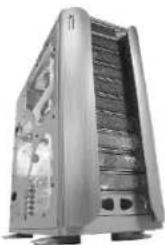
VA8000SWA
natural_image
Exterior view of a silver desktop computer tower with visible internal circuitry and ventilation slots (no text or symbols)| Model | Armor --- VA8000SWA |
| Case Type | Super TowerCase Type |
| Side Panel | Transparent side panel |
| Net Weight | 7.5 Kg |
| Dimension | 530 x 220 x 560 mm (H*W*D) |
| Cooling System | ●Front (intake) : 120 x 120 x25 mm blue LED fan, 1300rpm, 17dBA●Rear (Exhaust) : 120 x 120 x25 mm blue LED fan, 1300rpm,17dBA &90 x 90 x 25mm,1800rpm,19dBA●Top (Exhaust) : 90 x 90 x 25mm, 1800rpm, 19dBA |
| Drive Bays | 11 |
| -Front Accessible | Up to 10 x 5.25", 22x3355" |
| -Internal | 6 x 3.5" |
| Material | Chassis: 1.0 mm AluminumFront bezel: Aluminum |
| color | Silver |
| 7Expansion Slots | |
| Micro ATX, ATX, Extend ATX, BTX Motherboards | |
| BTX upgraded kits (option : A9358) | SRM / Rear plate |
natural_image
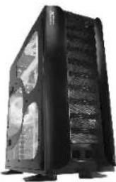
Black desktop computer tower case with visible internal circuitry and ventilation slots (no text or labels)| Model | Armor ---VA8000BWS |
| Case Type | Super TowerCase Type |
| Side Panel | Transparent side panel |
| Net Weight | 16.2Kg |
| Dimension | 530 x 220 x 560 mm (H*W*D) |
| Cooling System | •Front (intake) : 120 x 120 x25 mm blue LED fan, 1300rpm, 17dBA•Rear (Exhaust) : 120 x 120 x25 mm blue LED fan, 1300rpm,17dBA & 90x90 x25mm,1800rpm,19dBA•Top (Exhaust) : 90 x 90 x 25mm, 1800rpm, 19dBA |
| Drive Bays-Front Accessible-Internal | 11Up to 110x55285'2,123x5.5"6 x 3.5" |
| Material | Chassis: 1.0 mm SECCFront bezel: Aluminum |
| color | Black |
| 7Expansion Slots | |
| Micro ATX, ATX, Extend ATX, BTX Motherboards | |
| BTX upgraded kits (option : A9358) | SRM / Rear plate |
VA8000BWS
Chapter2 Case Mechanical Operation
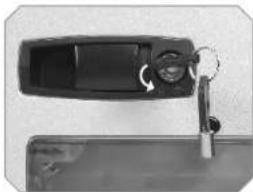
2.1 How to open the side panel
natural_image
Close-up of a black plastic object with a key inserted, partially open to a surface (no visible text or symbols)To find out the side panel key from the back side of the case then open it as the picture.

natural_image
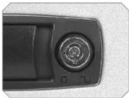
Close-up of a black electronic device handle with a circular button and control knob (no visible text or symbols)Make sure the side panel lock is opened.

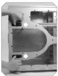
natural_image
Close-up of hands operating a mechanical component with a curved housing and mounting holes (no visible text or symbols)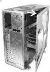
natural_image
Exterior view of a computer tower case showing internal components and ventilation ducts (no text or symbols visible)Push the button then swing out the side panel.

2.2 Installing 5.25" Device
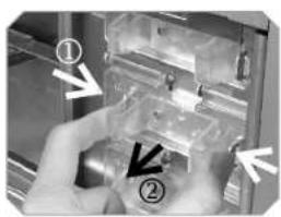
natural_image
Close-up of hands installing or adjusting a mechanical component with numbered arrows (no text or symbols visible)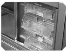
natural_image
Interior view of a refrigerator with visible shelves and glass panels (no text or symbols)Squeeze and pull out-ward the tool-free clip

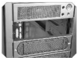
natural_image
Close-up of a desktop computer tower case showing front panel, grille, and rack (no visible text or labels)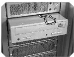
natural_image
Close-up of a desktop computer tower with drive bays and ventilation grilles (no visible text or labels)Remove the drive bay cover from the selected position, then insert the device into the 5.25" drive bay

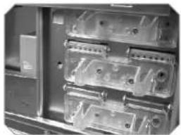
natural_image
Interior view of a computer case showing multiple drive bays and ventilation slots (no visible text or labels)Squeeze and push in-ward the tool-free clip.

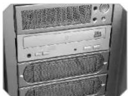
natural_image
Front view of a desktop computer tower rack with ventilation grilles and drive bays (no visible text or labels)Finish installation

User's Maunal
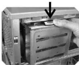
2.3 Installing 3.5" HDD
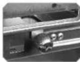
Unscrew the thumb screw for removable HDD cage
natural_image
Close-up of a computer tower with an arrow pointing to a drive or cable component (no visible text or symbols)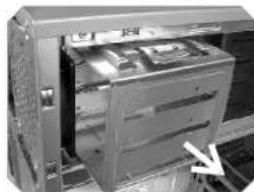
natural_image
Interior view of a computer drive bay with visible internal components and a white arrow pointing to a component (no text or symbols)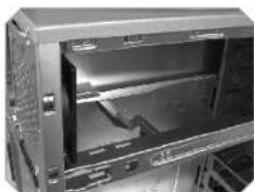
natural_image
Interior view of a server rack unit with open door and drive bays (no visible text or labels)Push down and hold the metal tab, then pull the HDD cage out-ward to remove from chassis.
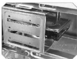
natural_image
Close-up of a computer drive bay with multiple drive bays and a central drive (no visible text or labels)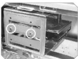
natural_image
Interior view of a computer drive showing two labeled components (3 and 5) with no visible text or symbols.Secure HDD with Screw
2.4 Removable 12cm Fan cage with 3HDD
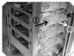
natural_image
Interior view of a server rack with numbered components and directional arrows indicating movement (no readable text or symbols)Squeeze and pull out-ward the tool-free clip
Note: Remove 12 cm fan cage is secured with 3 tool-free clips. Be sure to free all 3 tool-free clips
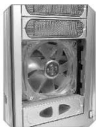
natural_image
Close-up of a computer tower fan with visible internal blades and ventilation slots (no text or symbols)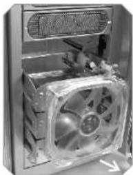
natural_image
Close-up of a computer tower fan with visible cooling effect and ventilation slots (no text or symbols)After loosen tool-free clip, remove 3 drive bay covers located in front of the 12 cm fan cage. Then slide the fan cage out-ward to remove.
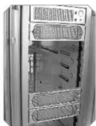
natural_image
Exterior view of a stainless steel industrial cabinet with ventilation grilles and internal compartments (no visible text or symbols)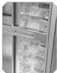
natural_image
Interior view of a refrigerator with shelves stocked with refrigerators (no visible text or labels)Remove another 3 drive bay covers at desired location for 12 cm fan cage Squeeze and pull out-ward the tool-free clip at desired location
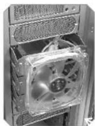
natural_image
Close-up of a computer tower CPU socket with visible fan and drive mechanism (no text or symbols)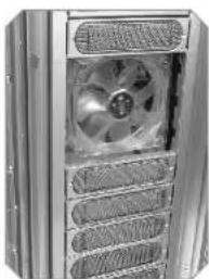
natural_image
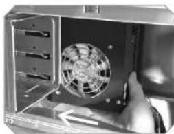
Close-up of a metallic industrial fan with ventilation grilles (no visible text or symbols)Insert the 12 cm fan cage into the desired location by sliding the cage in-ward from the front of chassis.
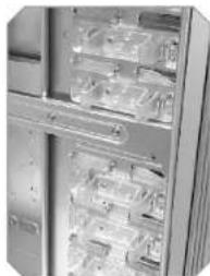
natural_image
Close-up of a refrigerator with visible door, shelves, and ventilation slots (no text or symbols)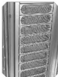
natural_image
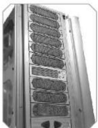
Close-up of a metallic panel with multiple recessed compartments (no text or symbols visible)Squeeze and push in-ward the tool free clip to secure the 12 cm fan cage.
Replace back the 3 drive bay covers previously removed
2.5 Installing 3.5" HDD (For 12cm Fan Cage)
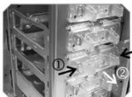
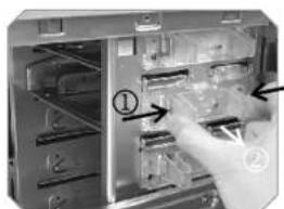
natural_image
Close-up of a server rack cabinet with numbered components (① and ②) and directional arrows indicating assembly or movement (no readable text or symbols)Squeeze and pull out-ward the tool-free clip at desired slot.
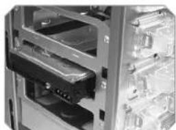
natural_image
Close-up of a server rack with multiple drive bays and a highlighted internal component (no visible text or labels)Insert HDD by sliding HDD into the 12 cm fan cage.
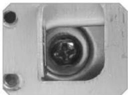
natural_image
Close-up of a metallic mechanical component with a central circular recess and two mounting holes (no visible text or symbols)Secure HDD by tightening screw to HDD
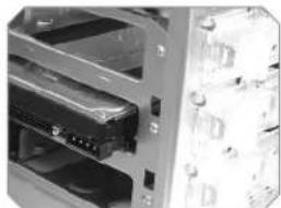
natural_image
Close-up of a server rack unit with multiple drive bays and ventilation slots (no visible text or labels)Squeeze and push in-ward the tool free clip to secure the HDD in the 12 cm fan cage.
2.6 5.25" to 3.5" Drive Tray Device Installation.
natural_image
Interior view of a computer or electronic device with labeled components (no readable text or symbols)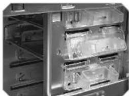
natural_image
Interior view of a refrigerator with visible door, shelves, and storage compartments (no text or symbols)Squeeze and pull out-ward the tool-free clip securing the drive tray
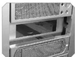
natural_image
Close-up of a computer tower case showing ventilation grilles and drive bays (no text or symbols visible)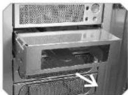
natural_image
Interior view of a computer oven with ventilation grilles and a door (no visible text or labels)Remove drive bay cover in front of the drive tray. Then slide out the device tray.
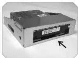
natural_image
Exterior view of a beige internal computer drive (no visible text or labels)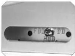
natural_image
Metal mechanical component with two circular holes and a central circular mark (no visible text or symbols)Insert HDD drive into device tray. Secure HDD with screw from the side of device tray labeled HDD.
natural_image
Close-up of a computer tower rear panel showing drive bays and a label with an arrow pointing to the front panel (no readable text or symbols)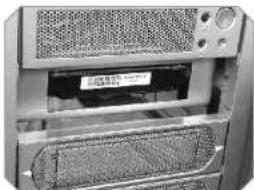
natural_image
Close-up of a computer tower case showing ventilation grilles and drive slots (no visible text or symbols)Insert back the device tray and replace back the drive bay cover.
natural_image
Interior view of a refrigerator with visible door, shelves, and storage compartments (no text or symbols)Squeeze and push in-ward the tool free clip to secure the device tray.
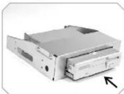
Installing Floppy Disk Drive to Device tray
natural_image
Exterior view of a beige internal computer drive (no visible text or labels)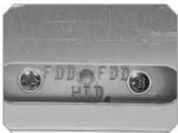
natural_image
Close-up of a metallic electronic component with two circular pins (no visible text or symbols)Remove device tray and insert floppy disk drive into device tray. Secure FDD with screw from the side of device tray labeled FDD.
natural_image
Close-up of a server rack with ventilation grilles and drive bays (no visible text or symbols)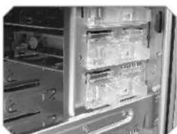
natural_image
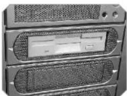
Close-up of a refrigerator interior showing glass doors and doorways (no visible text or symbols)Insert back device tray. Remove mesh on drive bay cover. Then replace back drive bay cover. Squeeze and push in-ward the tool free clip to secure the device tray
2.7 Installing 3.5" Device to Drive Tray With Power Button
natural_image
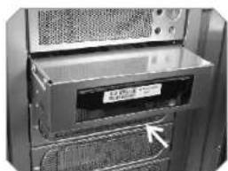
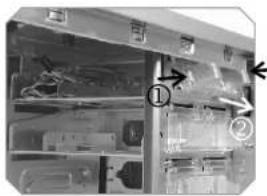
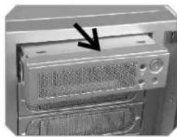
Close-up of a computer tower case with ventilation grilles and a black arrow pointing to the cover (no text or symbols visible)Squeeze and pull out-ward the tool-free clip securing the drive tray with power button. Remove and slide drive bay out-ward to remove.
natural_image
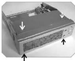
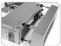
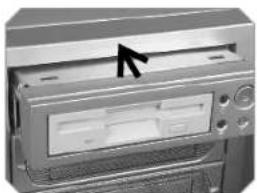
Exterior view of a computer tower case with ventilation grilles and mounting points (no text or symbols visible)Squeeze both top and bottom portion of drive tray cover picture to the left to remove cover.
natural_image
Close-up of a mechanical component with a pointed tool inserted, showing a perforated surface (no text or symbols visible)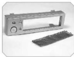
natural_image
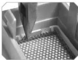
Exterior view of a metallic automotive air vent with control panel and two separate electrical connectors (no text or symbols visible)Remove mesh from cover
natural_image
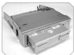
Exterior view of a modern office building (no signage)Place cover back to drive tray to its original position. Insert 3.25" device and secure device with screw.
natural_image
Exterior view of a computer drive chassis (no visible text or labels)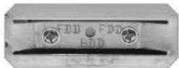
natural_image
Close-up of a computer monitor with an arrow pointing to the front panel (no visible text or symbols)Insert back the device tray pictured above. Squeeze and push in-ward the tool free clip to secure the device tray
natural_image
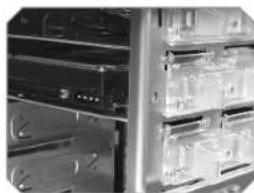
Interior view of an industrial equipment cabinet with shelves, fans, and control panels (no visible text or labels)Drive tray with Power Button can be placed at any drive bay desired.
natural_image
Front view of a server rack unit with multiple drive bays (no visible text or labels)2.8 Installing Power Supply
natural_image
Close-up of a computer fan inside a drive bay, showing internal components and no visible text or symbols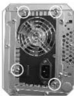
Install power supply unit as shown in pictures
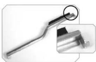
natural_image
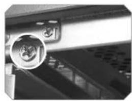
Close-up of a metallic tool with a circular annotation highlighting a specific feature (no text or symbols visible)
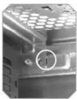
Locate the hook of PSU supporter on the hole which is circled in photo above
natural_image
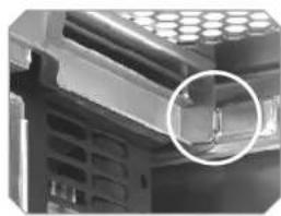
Close-up of a mechanical component with a magnified inset showing a small rectangular feature (no text or symbols visible)Swing the supporter to its proper position as shown in photo above
natural_image
Close-up of a computer mouse with a circular inset showing a close-up of the mouse (no text or symbols visible)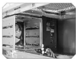
natural_image
Interior view of an electrical cabinet with visible wiring and components (no text or symbols)Secure the supporter with screw
2.9 Installing the fan on top of the case
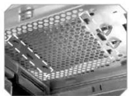
natural_image
Close-up of a microchip or electronic component with hexagonal grid pattern and internal components (no visible text or symbols)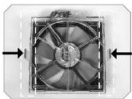
natural_image
Close-up of a computer fan with visible cooling effect and directional arrows (no text or symbols)Press-in 2 clips on the side of fan
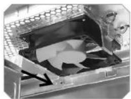
natural_image
Close-up of a computer fan with visible internal components and a black arrow indicating a motion (no text or symbols)Align all clips with mounting holes, then push-in the fan against case body to secure it.
natural_image
Close-up of a perforated metal panel with a hand holding a tool, showing no visible text or symbols.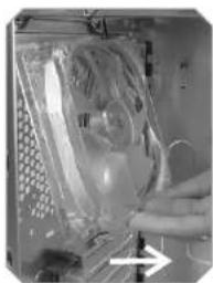
natural_image
Close-up of a hand holding a transparent plastic bag with a circular inset, next to a grid-patterned device (no visible text or symbols)Push fan clip upward to loose fan, then remove fan holder from inside
9 cm rear fan
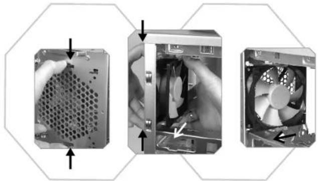
natural_image
Three-panel photo showing a computer tower with a mesh socket, a CPU fan emerging from the side, and a separate view of the tower's internal structure (no text or symbols visible)To remove fan & fan holder by press-in clips then pull both from inside. Please see above picture
2.11 Air Cooling System
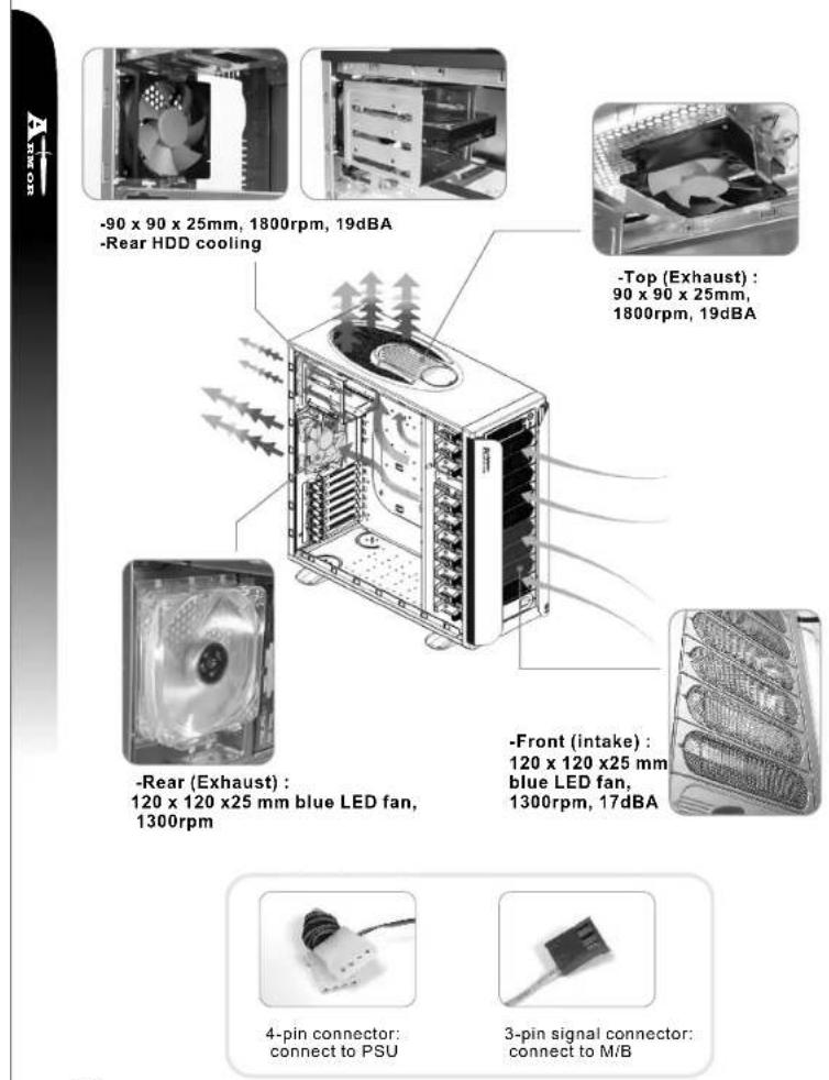
-90 x 90 x 25mm, 1800rpm, 19dBA
-Rear HDD cooling
-Rear (Exhaust) :
120 x 120 x25 mm blue LED fan,
1300rpm
4-pin connector: connect to PSU
3-pin signal connector: connect to M/B
2.12 BTX Upgraded Kits
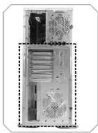
natural_image
Interior view of a computer tower case showing internal components and ventilation ducts (no text or labels visible)BTX rear plate
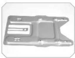
natural_image
Metallic mechanical part with internal slots and mounting holes (no visible text or symbols)BTX SRM (Supported Retention Module)
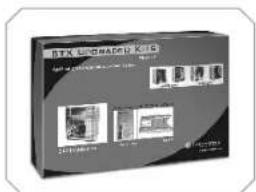
BTX upgraded kit box
2.13 PCI slot tool-free function operation
Open the plastic clip then take off the PCI bracket as follow.
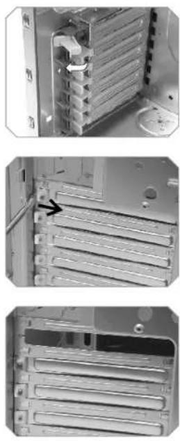
Chapter3 Motherboard & Leads Installation
3.1 Motherboard Installation
Each motherboard has different standoff layout. It is highly suggested that you refer to your motherboard's manual when installing motherboard into the case. The cases are applicable with Extend-ATX Standard ATX, Micro ATX motherboards. Your motherboard may require a special I/O Panel, which should be included with your motherboard.
Placement Direction:
When installing the motherboard, make sure you follow the direction provided by your motherboard manufacturer. On most standard motherboards, the edge with external ports goes to the rear part of the chassis. It is highly recommended that you install CPU, heat sink and modular components before fixing the motherboard inside the chassis.
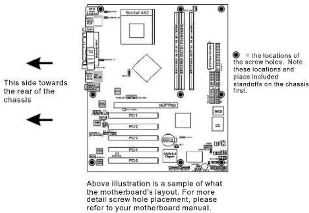
● = the locations of the screw holes. Note these locations and place included standoffs on the chassis first.
Above illustration is a sample of what the motherboard's layout. For more detail screw hole placement, please refer to your motherboard manual.
3.2 Case LED connections
natural_image
Close-up of a vintage electronic device with a mesh grille and control buttons (no visible text or symbols)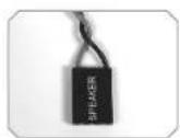
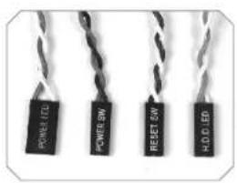
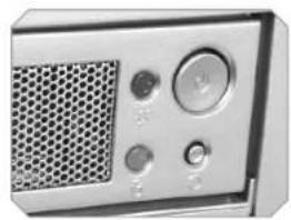
On the front of the case, you can find some LEDs and switch leads (POWER SW*1, POWER LED*1, H.D.D. LED*1, RESET SW*1, SPEAKER*1).
Please consult user manual of your motherboard manufacturer, then connect these leads to the panel header on the motherboard. These leads are usually labeled; if not, please trace them back to the case front to find out their source.
- POWER LED connects to your M/B at the PLED.
- POWER SW connects to the PWR connector on the motherboard.
- H.D.D LED connects to the 2-pin labeled HDDLED connector.
- RESET SW connects to the RSW connector on the motherboard.
- SPEAKER connector: find out the 4-pin labeled SPEAKER on the M/B then connect it.
3.3 USB2.0 & IEEE1394 Firewire connection
USB connection
Please consult your motherboard manual to find out the section of "USB connection".
| USB2.0 connection | ||||
| M/B layout (Ex: ASUS) | Case layout | |||
| 1 | USB+5V | VCC 1 | Red | USB 1 |
| 2 | LDM1 | DATA-1 | White | |
| 3 | LDP1 | DATA+1 | Green | |
| 4 | GND | GND 1 | Black | |
| 5 | NC | SHIELD 1 | Black | |
| 6 | USB+5V | VCC 2 | Red | USB 2 |
| 7 | LDM2 | DATA-2 | White | |
| 8 | LDP2 | DATA+2 | Green | |
| 9 | GND | GND 2 | Black | |
| 10 | -- | SHIELD 2 | Black | |
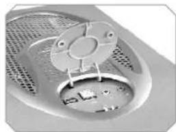
natural_image
Close-up of a mechanical component with a circular housing and mesh pattern (no visible text or symbols)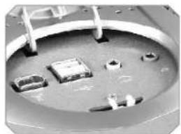
natural_image
Close-up of a mechanical component with multiple small components and a curved surface (no visible text or symbols)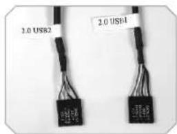
IEEE1394 Firewire connection
Please consult your motherboard manual to find out the section of "IEEE1394 Firewire connection".
| 1394 Firewire connection | |||
| M/B layout (Ex: ASUS) | Case layout | ||
| 1 | +12V | VP | White |
| 2 | Ground | VG | Black |
| 3 | TPB- | TPB- or TPB* | Red |
| 4 | TPB+ | TPB+ or TPB | Green |
| 5 | TPA- | TPA- or TPA* | Orange |
| 6 | TPA+ | TPA+ or TPA | Blue |
| 7 | Ground | Ground | Black |
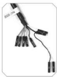
natural_image
Close-up of a black cable with multiple connectors and wires, no visible text or symbols3.4 Ear & MIC connections
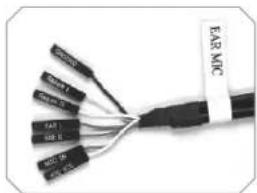
Please consult your motherboard manual to find out the section of "front panel audio connector".
| Ear & Mic connection | |||
| M/B layout (Ex: ASUS) | Case layout | ||
| 1 | LINE_OUT R | EAR R | Red |
| 2 | LINE_IN R | Return R | White |
| 3 | LINE_OUT L | EAR L | Green |
| 4 | LINE_IN L | Return L | Yellow |
| 5 | MIC | MIC IN | Red |
| 6 | MIC PWR | MIC VCC or MICBIAS | White |
| 7 | Ground | Ground | Black |
natural_image
Close-up of a black cable with multiple labeled connectors (no readable text or symbols)3.5 Case open alarm function (Intrusion switch)
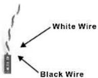
To find out the cable with 2pin connector (Micro SW) from the rear of inside the chassis.
2 To find out the position of Chassis Alarm on your motherboard. (please consult your motherboard manual)
Chapter4 Other
4.1 Silent Purepower ^TM power supply (optional)
The Thermaltake Silent™ Purepower specification meets Intel Pentium 4 and AMD K7; it offers plenty of functions, which mainly include:
- Automatic Fan Speed Control: The Silent Purepower™ power supply can detect the inside heat and automatically adjust the fan speed to provide adequate airflow.
- Ultra Silent: Ball bearing fans with high reliability and super low acoustic noise under all load condition.
The functions can assure the Silent Purepower ^™ meet the balance in noise control and heat exhausted. The Silent Purepower ^™ provides complete protection function as follow:
- Over thermal protection at 100^ C- 105^ C
- Short circuit protection on all output.
- Over voltage protection / Under voltage protection.
- Over current protection.
Besides, Thermaltake enables the quality assurance of the Silent Purepower ^™ 100% Hi-POT and ATE Function Test, 100% Burn-In and AC Input cycled on/off under high temperature condition. Furthermore, it has been approved by UL, CSA, TUV, VDE, NODIC, CB, FCC, CE, CNS.
natural_image
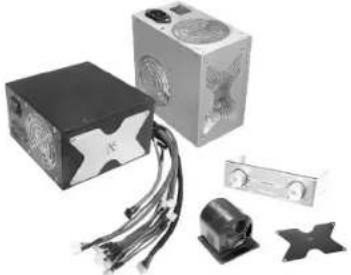
Product photo of a computer power supply unit with circuit board, motor, and star-shaped components (no visible text or symbols)There are three main products of Thermaltake PSU, it is divided into standard, VR and specialty power supply unit. Please refer to http://www.thermaltake.com/purepower/main.htm
Important Notice -
Contents below are additional information for proper motherboard installation for Thermaltake Armor (page 18) / Kandalf (page 20) Full Tower Chassis.
natural_image
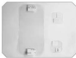
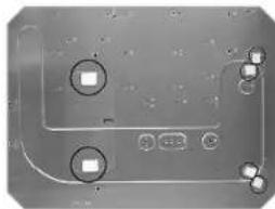
Two rectangular objects with small square cutouts on a white surface, no visible text or symbols.Inside the accessory box, please locate the Mylars (clear plastic films).
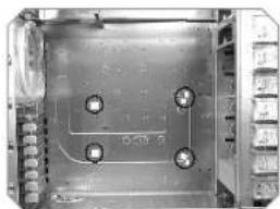
*Note: Due to the unique design of the Armor / Kandalf Chassis, these Mylar tapes are included to prevent ATX motherboards from contacting the chassis.
natural_image
Close-up of a metallic electronic component with four circular features and mounting holes (no visible text or symbols)Remove the adhesive backing and place the Mylars over each locations as shown.
natural_image
Interior view of an electronic device casing with visible circuitry and mounting holes (no text or symbols)Completed. Please note the Mylar tapes included are transparent. The image here is for reference only.
*Note: When assembling BTX motherboards into the Armor / Kandalf chassis, these Mylar tapes are not necessary.
natural_image
Close-up of a metal rack with multiple oval-shaped filter bands (no text or symbols visible)
- Contents
- Chapter1 Product Introduction
- Chapter2 Case Mechanical Operation
- Chapter3 Motherboard & Leads Installation
- Chapter4 Other
- Specification
- How to open the side panel
- Installing 5.25" Device
- Installing 3.5" HDD
- Removable 12cm Fan cage with 3HDD
- Installing 3.5" HDD (For 12cm Fan Cage)
- 5.25" to 3.5" Drive Tray Device Installation.
- Installing Power Supply
- PCI slot tool-free function operation
- Motherboard Installation
- Placement Direction:
- Case LED connections
- USB2.0 & IEEE1394 Firewire connection
- USB connection
- IEEE1394 Firewire connection
- Ear & MIC connections
- Case open alarm function (Intrusion switch)
- Silent Purepower TM power supply (optional)
- Important Notice -
Brand : THERMALTAKE
Model : Armour VA8000
Category : Computer Case