S4WA - Pregnant Syrincs - Free user manual and instructions
Find the device manual for free S4WA Syrincs in PDF.


User questions about S4WA Syrincs
0 question about this device. Answer the ones you know or ask your own.
Ask a new question about this device
Download the instructions for your Pregnant in PDF format for free! Find your manual S4WA - Syrincs and take your electronic device back in hand. On this page are published all the documents necessary for the use of your device. S4WA by Syrincs.
USER MANUAL S4WA Syrincs
1 General information about this manual 4
2 For your safety 5
3 Features 7
4 Installation 8
5 Connections and controls 10
6 Technical specifications 12
7 Plug and connection assignment 15
8 Protecting the environment 18
1 General information about this manual
This user manual contains important instructions for the safe operation of the unit. Read and follow the safety instructions and all other instructions. Keep the manual for future reference. Make sure that it is available to all those using the device. If you sell the unit, please make sure that the buyer also receives this manual.
Our products are subject to a process of continuous development. Thus, they are subject to change.
Signal words used
All precautions in this manual are clearly highlighted. The following signal words are used for precautions:
| DANGER This warns of dangers that can result in severe injuries or death if the instructions are not followed. |
| WARNING This warns of dangers that can result in severe injuries or death and/or cause considerable material damage if the instructions are not followed. |
| CAUTION This warns of dangers that can result in reversible injuries and/or considerable material damage if the instructions are not followed. |
| NOTICE This warns of dangers that can result to faults during operation and/or considerable material damage. Environmental damage may also occur if the instructions are not followed. |
Symbols used
 | General warning of a dangerous location |
 | Notice |
2 For your safety
Intended use
This device is designed as a PA system. Use the device only as described in this user manual. Any other use or use under other operating conditions is considered to be improper and may result in personal injury or property damage. No liability will be assumed for damages resulting from improper use.
This device may be used only by persons with sufficient physical, sensorial, and intellectual abilities and having corresponding knowledge and experience. Other persons may use this device only if they are supervised or instructed by a person who is responsible for their safety.
Safety instructions

DANGER
Danger for children
Ensure that plastic bags, packaging, etc. are properly disposed of and are not in the reach of babies and young children. Choking hazard!
→ Ensure that children do not detach any small parts (e.g. knobs or the like) from the product. They could swallow the pieces and choke!
→ Never let children play unattended with the electrical devices.

CAUTION
Possible hearing damage
The device can produce volume levels that may cause temporary or permanent hearing impairment. Over an extended period of time, even levels that seem to be uncritical can cause hearing damage.
→ Decrease the volume level immediately if you experience ringing in your ears or hearing impairment. If this is not possible, keep a greater distance or use sufficient ear protectors.

NOTICE
Operating conditions
This device has been designed for indoor use only.
→ To prevent damage, never expose the device to any liquid or moisture. Avoid direct sunlight, heavy dirt, and strong vibrations.
3 Features
Special features of this active subwoofer:
- XLR/1/4" jack combo-socket and RCA installation socket for signal input
- XLR chassis connector for signal output
- Integrated digital amplifier with sound processor (DSP)
- Setting options and display for delay time, crossover frequency and volume
- Switchable phase
- Power supply via locking PowerCON input
- Multiplex housing
- Pole mount (M20)
Optionally available accessories:
- Transport casters
4 Installation
Unpack the device and check carefully that there is no transportation damage before using the unit. Keep the equipment packaging. To fully protect the product against vibration, dust and moisture during transportation or storage use the original packaging or your own packaging material suitable for transport or storage, respectively.
Create all connections while the device is off. Use the shortest possible high-quality cables for all connections.

CAUTION
Risk of injury due to heavy weight
Due to the heavy weight of the device, at least two persons are required for transport and installation.

NOTICE
Possible property damage by magnetic fields
Loudspeakers produce a static magnetic field.
→ Therefore maintain an appropriate distance to devices that can be adversely affected or damaged by an external magnetic field.
We recommend you to set up the speakers in a way, that their sound signals can reach the audience unobstructedly. It will often be helpful to mount the speakers on tripods. Thus, the sound will be evenly spread with maximum range throughout the audience area.
Always use high grade cables to connect your equipment. Otherwise you won't reach maximum sound quality.
For optimum results both impedance and power rating of the speaker must match the requirements of the amplifier / input signal. Consider the technical specifications of the speakers connected. The overall impedance of the connected loudspeakers shall not be less than the minimum output impedance of the amp. The amps max. RMS output power should be 50 % above the power handling capacity of the connected speakers.
If you notice distortion during operation, either the amp or the speaker is overloaded. This may permanently damage the amp or the speaker. Always reduce the volume as soon as you notice distortion.
5 Connections and controls
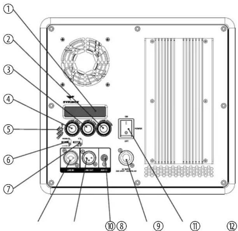
text_image
Labeled diagram of an electronic device panel with numbered components and control buttons1 Display. Shows the set values for delay time, crossover frequency and volume.
2 VOLUME
Volume control.
3 X-OVER
Control for adjusting crossover frequency.
4 DELAY
Control for adjusting delay time. This allows you to balance out time differences when speakers are arranged at an offset.
| 5 Control LEDs |
| - LIMIT: The red LED indicates that the limiter has been triggered. |
| - SIGNAL: The green LED indicates that a signal is present at the input. |
| - POWER: The green LED lights up when the device is turned on. |
| 6 DELAY |
| Switch for locking delay time setting. In the "enable" position, the delay time can be set using the DELAY (2) control. In the "disable" position, the last delay time set is maintained. |
| 7 PHASE |
| Phasing switch. Shifts the phase of the subwoofer signal by 180°, if necessary. This avoids unwanted cancellation effects in combination with other speakers. |
| 8 LINE IN |
| Line signal input, designed as XLR / 1/4" combo socket. |
| 9 LINE OUT |
| Line output for connecting further speakers, designed as XLR chassis plug. |
| 10 AUX IN |
| Signal input for additional audio devices like MP3 or CD players. |
| 11 AC INPUT |
| Power supply input powerCON (NAC3FA). |
| 12 POWER |
| Main switch. Turns the device on and off. |
6 Technical specifications
S4WA
| Configuration 12-inch-neodymium-woofer |
| Power handling 1000 W (RMS) |
| Maximal sound pressure 125 dB (1 m)131 dB (peak) |
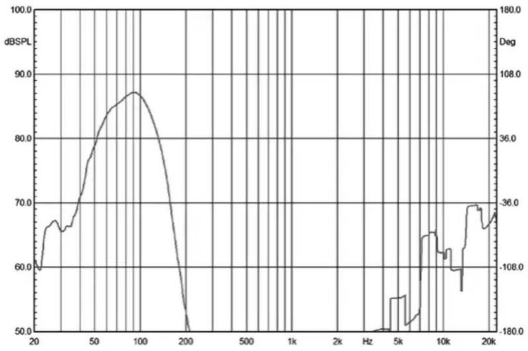
| Frequency range 50 Hz ... 120 Hz (-3 dB) |
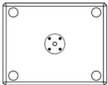
| Dimensions (W × H × D) 550 mm × 360 mm × 438 mm |
| Weight 23 kg |
natural_image
Simple 3D rectangular frame with four corner holes and a central circular hole (no text or symbols)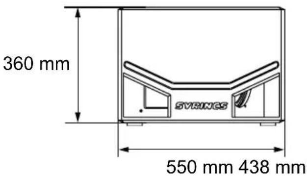
text_image
360 mm SVRINGS 550 mm 438 mm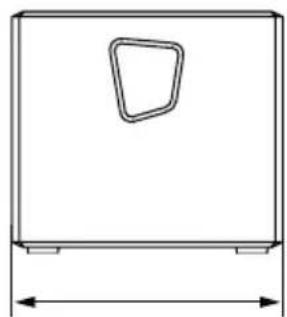
natural_image
Simple line drawing of a rectangular box with a small triangular cutout on top and two side supports at the bottom (no text or symbols)S5WA
| Configuration 15-inch-neodymium-woofer |
| Power handling 1000 W (RMS) |
| Maximal sound pressure 126 dB (1 m)132 dB (peak) |
| Frequency range 50 Hz ... 120 Hz (-3 dB) |
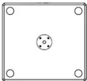
| Dimensions (W × H × D) 590 mm × 4400 mm × 550 mm |
| Weight 30 kg |
natural_image
Simple diagram of a square frame with four corner holes and a central circular hole (no text or symbols)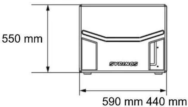
text_image
550 mm SYRINGS 590 mm 440 mm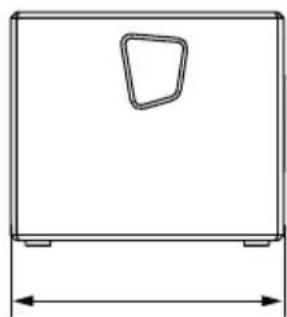
natural_image
Simple line drawing of a rectangular frame with a small triangular cutout on top and a dimension line below (no text or symbols)Frequency response S4WA
line
| Frequency | dBSPL | Deg | | --------- | ----- | ---- | | 20 | 60.0 | - | | 50 | 75.0 | - | | 100 | 87.0 | - | | 200 | 50.0 | - | | 5k | - | -180.0 | | 10k | - | -180.0 | | 20k | - | -180.0 |Frequency response S5WA
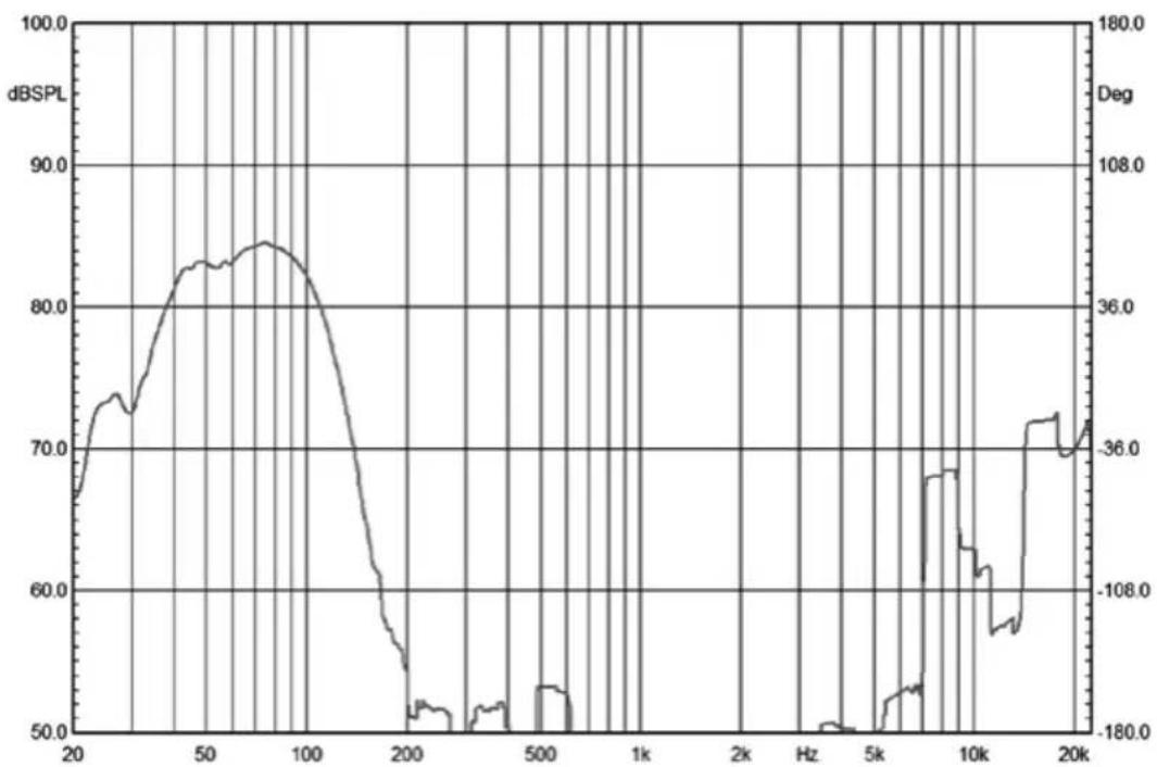
line
| Frequency | dB SPL | Deg | | --------- | ------ | --- | | 20 | 67.0 | 36.0 | | 50 | 83.0 | 108.0 | | 100 | 84.0 | 36.0 | | 200 | 52.0 | -180.0 | | 500 | 53.0 | -180.0 | | 1k | 52.0 | -180.0 | | 2k | 51.0 | -180.0 | | 5k | 50.0 | -180.0 | | 10k | 68.0 | -180.0 | | 20k | 72.0 | -36.0 |7 Plug and connection assignment
Introduction
This chapter will help you select the right cables and plugs to connect your valuable equipment in such a way that a perfect sound experience is ensured.
Please follow these tips, because special care is required when dealing with sound and light: Even if a plug fits into the socket, an incorrect connection may result in a destroyed power amp, a short circuit or just in poor transmission quality!
Balanced and unbalanced transmission
Unbalanced transmission is mainly used in semi-professional environment and in Hi-Fi use. Instrument cables with two conductors (one core plus shielding) are typical representatives of the unbalanced transmission. One conductor is ground and shielding while the signal is transmitted through the core.
Unbalanced transmission is susceptible to electromagnetic interference, especially at low levels, such as microphone signals and when using long cables.
In a professional environment, therefore, the balanced transmission is preferred, because this enables an undisturbed transmission of signals over long distances. In addition to the conductors ‘Ground’ and ‘Signal’, in a balanced transmission a second core is added. This also transfers the signal, but phase-shifted by 180^ .
Since the interference affects both cores equally, by subtracting the phase-shifted signals, the interfering signal is completely neutralized. The result is a pure signal without any noise interference.
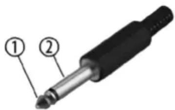
1/4" TS phone plug (mono, unbalanced)
text_image
Diagram of a 2-pin BJT connector with labeled parts ① and ②1 Signal
2 Ground
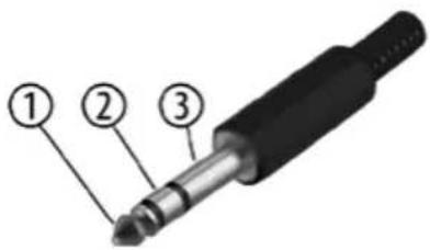
1/4" TRS phone plug (mono, balanced)
text_image
Diagram of a 3-pin electronic component with numbered parts labeled ①, ②, and ③.1 Signal (in phase, +)
2 Signal (out of phase, -)
3 Ground
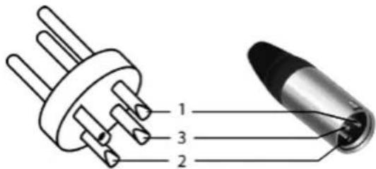
XLR connector (balanced)
text_image
1 3 21 Ground, shielding
2 Signal (in phase, +)
3 Signal (out of phase, -)
XLR connector (unbalanced)
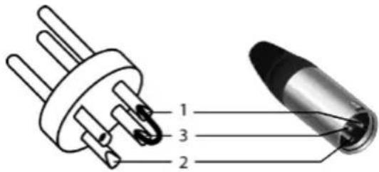
text_image
1 3 21 Ground, shielding
2 Signal
3 Jumpered with pin 1
RCA connections
The figure and the table show the pin assignment of an RCA connector.
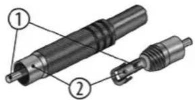
text_image
Technical diagram of a mechanical component with numbered parts labeled 1 and 21 Signal
2 Ground
8 Protecting the environment
Packaging

For the packaging, environmentally friendly materials have been chosen that can be supplied to normal recycling. Ensure that plastic bags, packaging, etc. are properly disposed of.
Do not just dispose of these materials with your normal household waste, but make sure that they are collected for recycling. Please follow the notes and markings on the packaging.
Disposal of your old device
This product is subject to the European Waste Electrical and Electronic Equipment Directive (WEEE) in its currently valid version. Do not dispose with your normal household waste.
Dispose of this device through an approved waste disposal firm or through your local waste facility. When discarding the device, comply with the rules and regulations that apply in your country. If in doubt, consult your local waste disposal facility.

natural_image
Silhouette of a bird with pointed beak and outstretched wings (no text or symbols)SYRINCS