
GRL4000-80CH - Rangefinder BOSCH - Free user manual and instructions
Find the device manual for free GRL4000-80CH BOSCH in PDF.

| Product Type | Laser Rangefinder |
| Model | GRL4000-80CH |
| Brand | Bosch |
| Measuring Range | 0.05 – 80 m |
| Measurement Accuracy | ±1.5 mm (typical) |
| Laser Class | Class 2 (635 nm, <1 mW) |
| Protection Class | IP 54 (dust and splash water protected) |
| Power Supply | 3.7 V Li-Ion rechargeable battery (built-in) |
| Operating Time | Up to 5 hours (continuous) |
| Dimensions (L x W x H) | 122 x 48 x 30 mm |
| Weight | 150 g (with battery) |
| Memory | Last 20 measurements |
| Bluetooth | Bluetooth 4.2 (for data transfer) |
| Measurement Modes | Distance, area, volume, indirect height (Pythagoras), continuous |
| Backlit Display | Yes |
| Auto-Laser OFF | After 20 s (manual) |
| Auto-Power OFF | After 3 min |
| Min/Max Measurement | Yes (tracking mode) |
| Addition/Subtraction | Supported |
| Stake Out Function | Yes |
| Operating Temperature | -10 °C to +50 °C |
| Storage Temperature | -20 °C to +70 °C |
| Maintenance | Clean lens with soft, dry cloth; do not use solvents |
| Safety Instructions | Do not stare into beam; laser class 2; avoid eye exposure |
| Spare Parts / Repairability | Contact Bosch service for battery replacement; other repairs by authorized centers |
| Warranty | 2 years (check local regulations) |
Frequently Asked Questions - GRL4000-80CH BOSCH
User questions about GRL4000-80CH BOSCH
0 question about this device. Answer the ones you know or ask your own.
Ask a new question about this device
Download the instructions for your Rangefinder in PDF format for free! Find your manual GRL4000-80CH - BOSCH and take your electronic device back in hand. On this page are published all the documents necessary for the use of your device. GRL4000-80CH by BOSCH.
USER MANUAL GRL4000-80CH BOSCH
IMPORTANT: IMPORTANT : IMPORTANTE: Read Before Using Lire avant usage Leer antes de usar

natural_image
Silhouette of a person reading a book inside a circle (no text or symbols)Operating/Safety Instructions Consignes de fonctionnement/sécurité Instrucciones de funcionamiento y seguridad
GRL4000-80CH GRL4000-80CHV RC5
natural_image
Exterior view of a Bosch electronic device with control panel (no visible text or symbols)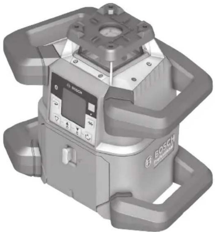
natural_image
3D rendering of a Bosch EFS-Mechanical device with control panel and mounting bracket (no visible text or symbols)
BOSCH
Call Toll Free for Consumer Information & Service Locations
text_image
(i) BOSCH ① YGRL4000-80CHV
natural_image
Diagram of a surveying or monitoring setup with tripod-mounted sensors and ground level, no visible text or symbols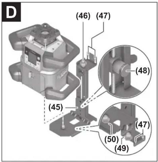
text_image
(46) (47) (48) (45) (47) (50) (49)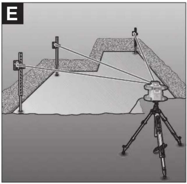
natural_image
Diagram of a surveying setup with tripod-mounted equipment and alignment wires, no visible text or symbols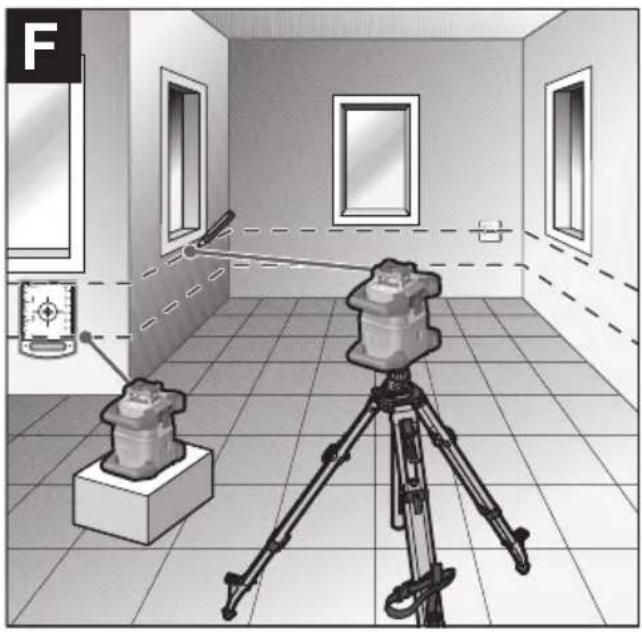
natural_image
Interior view of a room with a camera setup and a mounted device, no visible text or symbols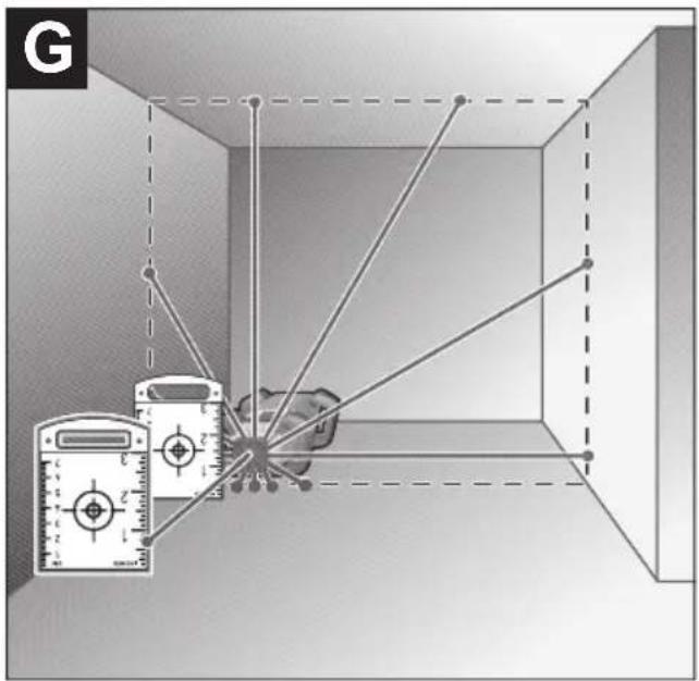
text_image
G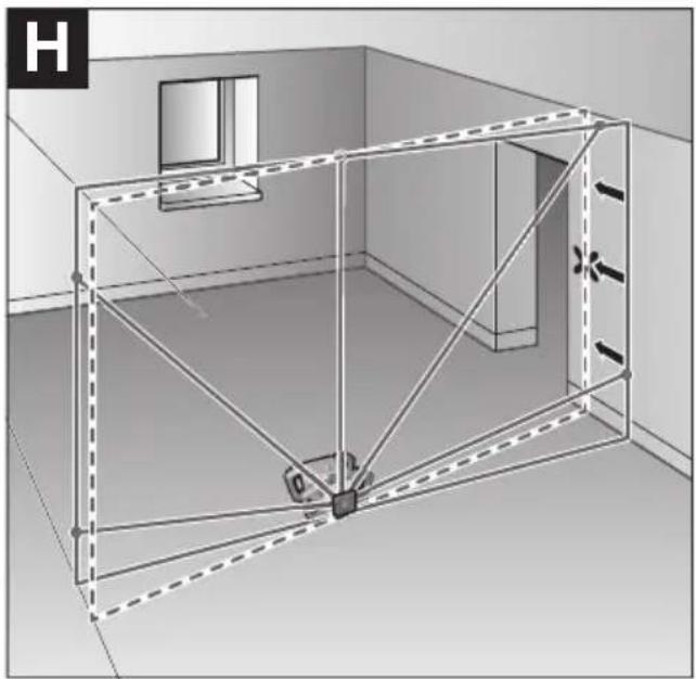
natural_image
3D architectural rendering of a room with walls, windows, and structural beams (no text or symbols)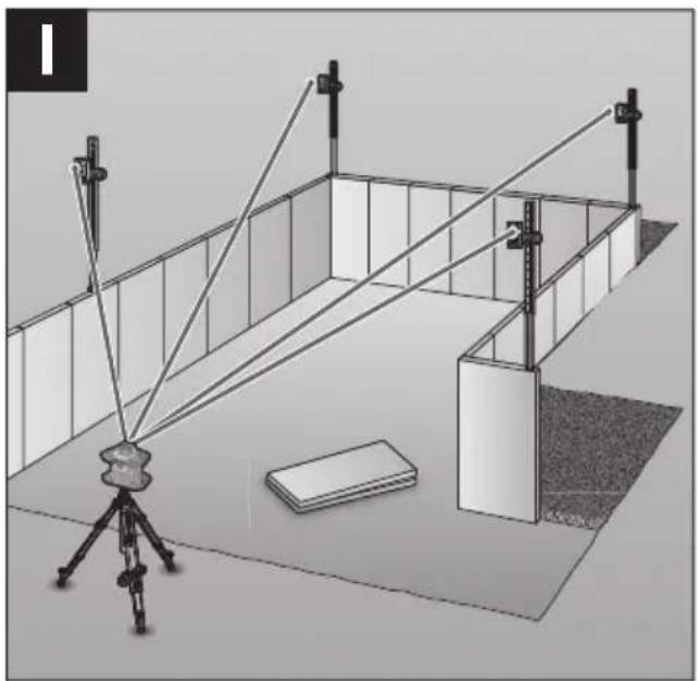
natural_image
Diagram of a 3D setup with a tripod-mounted camera and two vertical supports, no visible text or symbols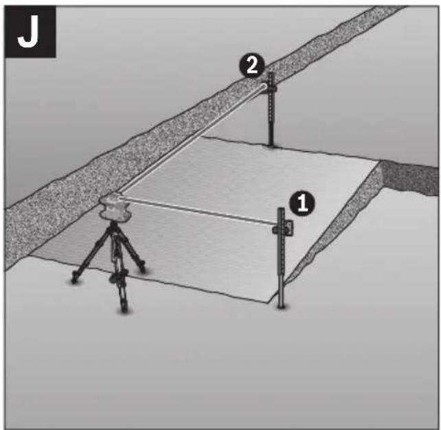
text_image
J 2 1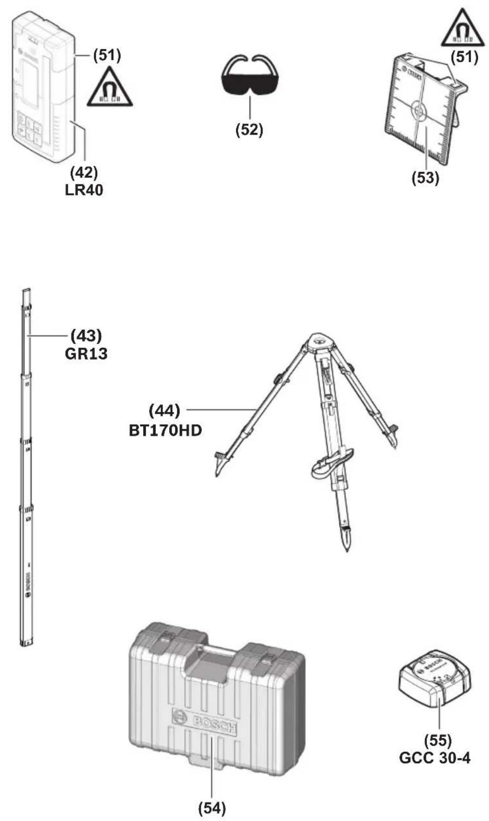
Safety Symbols
The definitions below describe the level of severity for each signal word. Please read the manual and pay attention to these symbols.
 | This is the safety alert symbol. It is used to alert you to potential personal injury hazards. Obey all safety messages that follow this symbol to avoid possible injury or death. |
 | Read manual symbol - Alerts user to read manual. |
 | WARNING indicates a hazardous situation which, if not avoided, could result in death or serious injury. |
 | This symbol designates that this laser leveling tool complies with Part 15 of the FCC Rules. |
General Safety Rules
WARNING
Read all instructions. Failure to follow all instructions listed below may result in hazardous radiation exposure, electric shock, fire and/or
SAVE ALL WARNINGS AND INSTRUCTIONS FOR FUTURE REFERENCE
The term “tool” in all of the warnings listed below refers to your mains-operated (corded) tool or battery-operated (cordless) tool.
WARNING
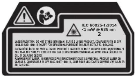
The following labels are on your laser tool for your convenience and safety. They indicate where the laser light is emitted by the tool. ARE of their location when using the tool.
text_image
IEC 60825-1:2014 <1 mW @ 635 nm 2 LASER RADIATION. DO NOT STARE INTO BEAM. CLASS 2 LASER PRODUCT. COUPLES WITH 21 CFR 1940.10 AND 1940.11 EXCEPT FOR DEVIVATIONS PURSUANT TO LASER NOTICE 50, 6/24/2007. RADIACION LASER. NO DIRE AL RAYO. PRODUCTO LASER DE CLASE 2. CUMPLE CAN LAS NORMAS 21 CFR 1940.10 Y 1940.11, EXCEPTO POR LAS DESVIVACIONES CONFORME AL ANISO PARA LASERES 50 DELTA DE JUNO DE 2007. RAYONEMENT LASER. NE REBARDEZ PAS DIRECTEMENT DAVIS LE FAISCEAU. PRODUIT LASER DE CLASSE 2. CONFORME A 21 CFR 1940.10 ET 1940.11, SAUF POUR LES ECARTS SURVIANT LAVIS LASER 50, 24/6/2007.
Do not direct the laser beam at persons or animals and do not stare into the laser beam yourself. This tool produces laser class 2 laser radiation and complies with 21 CFR 1040.10 and 1040.11 except for deviations pursuant to Laser Notice No. 50, dated June 24, 2007. This can lead to persons being blinded.
DO NOT remove or deface any warning or caution labels. Removing labels increases the risk of exposure to laser radiation.
WARNING
It is the user's responsibility to periodically check the accuracy of the laser level as work progresses. Always check the accuracy of the laser en dropped or subject to extreme temperatures and temperature variations.
level after it has been dropped or subject to extreme temperatures and temperature variations.
WARNING
If glass light house breaks when dropped, broken glass can cause laceration hazard and unit to lose its IP rating. Contact customer service
immediately.
Use of controls or adjustments or performance of procedures other than those specified in this manual, may result in hazardous radiation exposure.
ALWAYS make sure that any bystanders in the vicinity of use are made aware of the dangers of looking directly into the laser tool.
DO NOT place the laser tool in a position that may cause anyone to stare into the laser beam intentionally or unintentionally. Serious eye injury could result.
ALWAYS position the laser tool securely. Damage to the laser tool and/or serious injury to the user could result if the laser tool fails.
ALWAYS use only the accessories that are recommended by the manufacturer of your laser tool. Use of accessories that have been designed for use with other laser tools could result in serious injury.
DO NOT use this laser tool for any purpose other than those outlined in this manual. This could result in serious injury.
DO NOT leave the laser tool "ON" unattended in any operating mode.
DO NOT disassemble the laser tool. There are no user serviceable parts inside. Do not modify the product in any way. Modifying the laser tool may result in hazardous laser radiation exposure.
DO NOT use the laser viewing glasses as safety goggles. The laser viewing glasses are used for improved visualization of the laser beam, but they do not protect against laser radiation.
DO NOT use the laser viewing glasses as sun glasses or in traffic. The laser viewing glasses do not afford complete UV protection and reduce color perception.
DO NOT use any optical tools such as, but not limited to, telescopes or transits to view the laser beam. Serious eye injury could result.
DO NOT stare directly at the laser beam or project the laser beam directly into the eyes of others. Serious eye injury could result.
Work area safety
Keep work area clean and well lit. Cluttered or dark areas invite accidents.
DO NOT operate the laser tool around children or allow children to operate the laser tool. Serious eye injury could result.
DO NOT use laser tools, attachments and accessories outdoors when lightning conditions are present.
Do not operate the laser tool in explosive environments, such as in the presence of flammable liquids, gases or dusts. Sparks can be created in the laser tool which may ignite the dust or fumes.
Electrical safety
WARNING
Batteries can explode or leak, cause injury or fire.
To reduce this risk, always follow all instructions and warnings on the battery label and package.
DO NOT expose the laser tool and battery to rain or wet conditions. Water entering laser tool will increase the risk of fire and personal injury.
DO NOT short any battery terminals.
DO NOT charge alkaline batteries.
DO NOT mix old and new alkaline batteries. Replace all of them at the same time with new batteries of the same brand and type.
DO NOT mix battery chemistries.
Dispose of or recycle batteries per local code.
DO NOT dispose of batteries in fire.
Keep batteries out of reach of children.
Remove batteries if the device will not be used for several months.
Personal safety
If laser radiation strikes your eye, you must deliberately close your eyes and immediately turn your head away from the beam.
Do not make any modifications to the laser equipment.
Stay alert, watch what you are doing and use common sense when operating a tool. Do not use a tool while you are tired or under the influence of drugs, alcohol or medication. A moment of inattention while operating a tool may result in serious personal injury or incorrect measurement results.
Use safety equipment. Always wear eye protection. Safety equipment such as dust mask, non-skid safety shoes, hard hat, or hearing protection used for appropriate conditions will reduce personal injuries.
Use caution when using laser tools in the vicinity of electrical hazards.
Magnets
Keep the tool, wall mount, laser receiver, and laser target plate away from cardiac pacemakers.
The magnets of the tool and laser target plate generate a field that can impair the function of cardiac pacemakers.
Keep the tool, wall mount, laser receiver, and laser target plate away from magnetic data medium and magnetically-sensitive equipment. The effect of the magnets of the tool and laser target plate can lead to irreversible data loss.
Use and care
Use the correct tool for your application. The correct tool will do the job better and safer.
Do not use the tool if the switch does not turn it on and off. Any tool that cannot be controlled with the switch is dangerous and must be repaired.
Store idle tool out of the reach of children and do not allow persons unfamiliar with the tool or these instructions to operate the tool. Tools are dangerous in the hands of untrained users.
Maintain tools. Check for misalignment or binding of moving parts, breakage of parts and any other condition that may affect the operation. If damaged, have the tool repaired before use. Many accidents are caused by poorly maintained tools.
Use the tool, accessories, etc., in accordance with these instructions and in the manner intended for the particular type of tool, taking into account the working conditions and the work to be performed. Use of the tool for operations different from those intended could result in a hazardous situation.
Battery tool use and care
Recharge only with the charger specified by the manufacturer. A charger that is suitable for one type of battery pack may create a risk of fire when used with another battery pack.
Use laser tools only with specifically designated battery packs. Use of any other battery packs may create a risk of injury and fire.
When battery pack is not in use, keep it away from other metal objects like paper clips, coins, keys, nails, screws, or other small metal objects that can make a connection from one terminal to another. Shorting the battery terminals together may cause burns or fire.
Under abusive conditions, liquid may be ejected from the battery; avoid contact. If contact accidentally occurs, flush with water. If liquid contacts eyes, additionally seek medical help. Liquid ejected from the battery may cause irritation or burns.
Do not use a battery pack or tool that is damaged or modified. Damaged or modified batteries may exhibit unpredictable behavior resulting in fire, EXPLOSION or risk of injury.
Do not expose a battery pack or tool to fire or excessive temperature. Exposure to fire or temperature above 265 °F (130 °C) may cause explosion.
Follow all charging instructions and do not charge the battery pack or tool outside the temperature range specified in the instructions. Charging improperly or at temperatures outside the specified range may damage the BATTERY and increase the risk of fire.
Service
Have your tool serviced by a qualified repair person using only identical replacement parts. This will ensure that the safety of the tool is maintained.
Develop a periodic maintenance schedule for tool. When cleaning a tool be careful not to disassemble any portion of the tool since internal wires may be misplaced or pinched or may be improperly mounted. Certain cleaning agents such as gasoline, carbon tetrachloride, ammonia, etc., may damage plastic parts.
SAVE THESE INSTRUCTIONS.
FCC Caution

The manufacturer is not responsible for radio interference caused by unauthorized modifications to this equipment. Such modifications could void the user's authority to operate the equipment.
This device complies with Part 15 of the FCC Rules. Operation is subject to the following two conditions:
1) This device may not cause harmful interference, and
2) This device must accept any interference received, including interference that may cause undesired operation.
NOTE! This equipment has been tested and found to comply with the limits for a Class B digital devices, pursuant to Part 15 of the FCC rules. These limits are designed to provide reasonable protection against harmful interference in a residential installation. This equipment generates uses and can radiate radio frequency energy and, if not installed and used in accordance with the instructions, may cause harmful interference to radio communications. However, there is no guarantee that interference will not occur in a particular installation. If this equipment does cause harmful interference to radio or television reception, which can be determined by turning the equipment off and on, the user is encouraged to try to correct the interference by one or more of the following measures:
• Reorient or relocate the receiving antenna.
- Increase the separation between the equipment and receiver.
- Connect the equipment into an outlet on a circuit different from that to which the receiver is connected.
- Consult the dealer or an experienced radio/TV technician for help.
"Exposure to Radio Frequency (RF) Signals: The wireless device is a radio transmitter and receiver. It is designed and manufactured not to exceed the emission limit for exposure to radio frequency (RF) energy set by the Ministry of Health (Canada), Safety Code 6. These limits are part of comprehensive guidelines and established permitted levels of RF energy for the general population.
Industry Canada (IC)
This device complies with Industry Canada's licence-exempt RSSs. Operation is subject to the following two conditions:
(1) This device may not cause interference; and
(2) This device must accept any interference, including interference that may cause undesired operation of the device.
Features
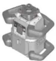
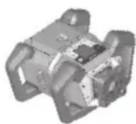
The numbering of the product features shown refers to the illustration of the tool on the graphic page.
Rotarylaser
(1) Battery compartment cover
(2) Battery compartment cover locking mechanism
(3) Slope button down ▼/Button for clockwise rotation ⬆
(4) Slope button up ▲/Button for anticlockwise rotation ♂
(5) Line operation button (6) Rotational operation button
(7) Bluetooth® button
(8) Variable laser beam
(9) Laser beam outlet aperture
(10) Upwards plumb point A)
(11) On/off button
(12) Status indicator
(13) Manual operation button
(14) Slope button
(15) Display
(16) Tripod mount 5/8" (horizontal)
(17) Carrying handle
(18) Notch for orientation
(19) Laser warning label
(20) Tripod mount 5/8" (vertical)
(21) Serial number
(22) Recess for Bluetooth® localization module
(23) Battery adapter
(24) Release button for rechargeable battery/battery adapter
(25) Rechargeable battery
A) In vertical mode, the upwards plumb point applies as a 90^ reference point.
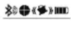
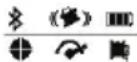
Rotary laser indicator elements
(a) Laser operating mode indicator
(b) Bluetooth® connection indicator
(c) Shock-warning function indicator
(d) Battery charge indicator for rechargeable battery/non-rechargeable batteries
(e) Plumb point function indicator (downwards)
(f) X-axis slope angle indicator
(g) Y-axis slope angle indicator
(h) Rotational speed indicator
(i) Softkey symbols
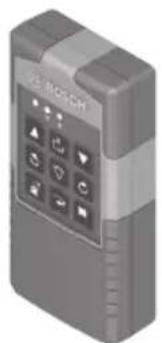
Remote control
(26) Plumb point function button (downwards)
(27) Rotational operation button
(28) Sleep mode button
(29) Line operation button
(30) Button for anticlockwise rotation
(31) Slope button, up
(32) Slope button
(33) Signal transmission indicator
(34) X-axis status indicator
(35) Y-axis status indicator
(36) Slope button, down
(37) Button for clockwise rotation
(38) Battery compartment cover locking mechanism
(39) Serial number
(40) Battery compartment cover
(41) Remote control
The numbering of the product features shown refers to the illustration of the tool on the graphic page.
Accessories/replacement parts
(42) Laser receiver
(43) Measuring rod A)
(44) Tripod A)
(45) Wall mount/alignment unit
(46) Wall mount fastening screw
(47) Wall mount fixing holes
(48) Push button for coarse adjustment of the wall mount
(49) Wall mount fine adjustment screw
(50) 5/8" wall mount screw
(51) Magnet
(52) Laser viewing glasses ^A)
(53) Laser target plate ^A)
(54) Case
(55) Bluetooth® localization moduleA)
A) Accessories shown or described are not included with the product as standard. You can find the complete selection of accessories in our accessories range.
Rotary Laser GRL4000-80CH GRL4000-80CHV
| Article number 3 601 K61 J10 3 601 K61 F10 | ||
| Working range (Diameter) | ||
| -without laser receiver | approx. 200 ft(approx. 60 m) | approx. 200 ft(approx. 60 m) |
| -with laser receiver | approx. 4000 ft(approx. 1200 m) | approx. 4000 ft(approx. 1200 m) |
| Leveling Accuracy ^1) ^2) | ||
| -Horizontal | ±1/16 in @ 100 ft(±1.5 mm/30m) | ±1/16 in @ 100 ft(±1.5 mm/30m) |
| -Vertical | ±1/8 in @ 100 ft(±3 mm/30m) | |
| Self-leveling range (typical) ±8.5% (±5°) ±8.5% (±5°) | ||
| Scan angle for line operation n/a 0°/10°/25°/50° | ||
| Leveling duration at a slope of up to ±3% 30s 30s | ||
| Rotational speed 600min | -1 | 150/300/600min-1 |
| Singe/dual-axis slope operation ±8.5% ±8.5% | ||
| Accuracy of single-axis slope operation B) | ±0.2% ±0.2% | |
| Max. altitude | 6560 ft(approx. 2000 m) | 6560 ft(approx. 2000 m) |
| Relative air humidity max. | 90% | 90% |
| Laser class 2 | 2 | |
| Laser type | 635 nm, <1 mW | 635 nm, <1 mW |
| Divergence of laser line | <1.5 mrad (full angle) | <1.5 mrad (full angle) |
| Recommended laser receiver | LR40 | LR40 |
| Tripod mount (horizontal/vertical) | 5/8 in-11 | 5/8 in-11 |
| Laser level power supply | ||
| -Rechargeable battery pack (Li-ion) | 18 V | 18 V |
| -Non-rechargeable batteries(alkaline manganese) (with battery adapter) | 4 x 1.5V LR20 (D) | 4 x 1.5V LR20 (D) |
| Approx. operating time | ||
| -with Lithium Ion (or rechargeable) battery (4 Ah) | 60 h | 60 h |
| -with non-rechargeable batteries | 70 h | 70 h |
| Bluetooth® laser level | ||
| -Class | 1 | 1 |
| -Compatibility | Bluetooth® 5.0/4.X(Low Energy) ^E) | Bluetooth® 5.0/4.X(Low Energy) ^E) |
| -Max. signal range | 328 ft (100 m) ^F) | 328 ft (100 m) ^F) |
| -operating frequency range | 2402-2480 MHz | 2402-2480 MHz |
| -Max. transmission power | 6.3 mW | 6.3 mW |
| Bluetooth® smartphone | ||
| -Compatibility | Bluetooth® 5.0/4.X(Low Energy) ^E) | Bluetooth® 5.0/4.X(Low Energy) ^E) |
| -Operating system | Android 6, iOS 10(and above) | Android 6, iOS 10(and above) |
| Rotary Laser GRL4000-80CH GRL4000-80CHV | ||
| Weight according to EPTA-Procedure 01:2014– with rechargeable battery^G) – with non-rechargeable batteries | 9.3–10.6 lb (4.2-4.8 kg)10 lb (4.6 kg) | 9.3–10.6 lb (4.2-4.8 kg)10 lb (4.6 kg) |
| Dimensions (length × width × height) 12.8 x 7.4 x 11 in(327 × 188 × 278 mm) | 12.8 x 7.4 x 11 in(327 × 188 × 278 mm) | |
| Protection rating IP 68 IP 68 | ||
| If mounted on a tripod, drop-proof to a height of 6 ft (2 m) 6 ft (2 m) | ||
| Recommended ambient temperatureduring charging | 32 °F ~ 95 °F(0 °C to +35 °C) | 32 °F ~ 95 °F(0 °C to +35 °C) |
| Permitted ambient temperature– during operation ^H) – during storage | 14 °F ~ 122 °F(-10 °C to +50 °C)-4 °F ~ 122 °F(-20 °C to +50 °C) | 14 °F ~ 122 °F(-10 °C to +50 °C)-4 °F ~ 122 °F(-20 °C to +50 °C) |
| Batteries Bosch GBA18V40 Bosch GBA18V40,GBA18V80GBA18V80 | ||
| Chargers Bosch GAL18V40 Bosch GAL18V40 | ||
A) The working range may be reduced by unfavorable environmental conditions (e.g. direct sunlight).
B) At 20^ C.
C) Along the axes.
D) At a maximum slope of ±8.5% , the maximum deviation is ±0.2% .
E) Only non-conductive deposits occur, whereby occasional temporary conductivity caused by condensation is expected.
F) When using Bluetooth® Low Energy devices, it may not be possible to establish a connection depending on the model and operating system. Bluetooth® devices must support the SPP profile.
G) The signal range may vary greatly depending on external conditions, including the receiving device used. The Bluetooth® range may be significantly weaker inside closed rooms and through metallic barriers (e.g. walls, shelving units, cases, etc.).
H) Depends on battery in use.
The serial number (21) on the type plate is used to clearly identify your measuring tool.
| Remote Control RC5 | |
| Article number 3 601 K69 R10 | |
| Working range (radius) 300 ft (100 m) | |
| Operating temperature | 14 °F ~ 122 °F (-10 °C to +50 °C) |
| Storage temperature | -4 °F ~ 158 °F (-20 °C to +70 °C) |
| Max. altitude | 6560 ft (approx. 2000 m) |
| Relative air humidity max. 90% | |
| Pollution degree according to IEC 61010-1 2 | A) |
| Bluetooth® remote control | |
| - Class | 1 |
| - Compatibility | Bluetooth® 5.0/4.X (Low Energy) ^B) |
| - Max. signal range | 328 ft (100 m) ^C) |
| - Operating frequency range | 2402-2480 MHz |
| - Max. transmission power | 6.3 mW |
| Batteries 2 × 1.5 V LR6 (AA) | |
| Weight according to EPTA-Procedure 01:2014 0.37 lb (0.17 kg) | |
| Dimensions (length × width × height) 4.8 × 2.3 × 1 in (122 × 59 × 27 mm) | |
| Protection rating IP 54 | |
A) Only non-conductive deposits occur, whereby occasional temporary conductivity caused by condensation is expected.
B) When using Bluetooth® Low Energy devices, it may not be possible to establish a connection depending on the model and operating system. Bluetooth® devices must support the SPP profile.
C) The signal range may vary greatly depending on external conditions, including the receiving device used. The Bluetooth® range may be significantly weaker inside closed rooms and through metallic barriers (e.g. walls, shelving units, cases, etc.).
Intended Use
Rotary laser
The laser level is intended for establishing and checking exactly horizontal height profiles, vertical lines, alignments and plumb points.
The laser level is suitable for indoor and outdoor use.
Remote control
The remote control is intended for controlling the Bosch rotary lasers via Bluetooth®.
The remote control is suitable for indoor and outdoor use.
Assembly
Laser level Power Supply
The laser level can be operated either with conventional non-rechargeable batteries or with a Bosch lithium-ion battery.
Do not use any commercially available rechargeable batteries (e.g. nickel metal hydride).
Operation with Bosch Rechargeable Lithium-ion Battery Pack
WARNING
Use only Bosch rechargeable lithium-ion battery
packs listed in the technical data section of this manual. Use of other battery packs may increase the risk of fire, personal injury and property damage.
Note: The battery pack is supplied partially charged. To ensure full capacity of the battery pack, completely charge the battery pack in the battery charger before using for the first time.
WARNING
Use only Bosch chargers listed in the technical
data section of this manual. Use of other chargers may increase the risk of fire, personal injury and property damage.
The lithium-ion battery pack can be charged at any time without reducing its service life. Interrupting the charging procedure does not damage the battery pack.
The “Electronic Cell Protection (ECP)” protects the lithium-ion battery pack against deep discharging. When the battery pack is discharged, the laser tool is switched off by a protective circuit.
▶ Do not switch the laser level back on after it has been switched off by the protective circuit. This can damage the battery.
Battery charge indicator
If the rechargeable battery is removed from the laser level, its state of charge may be indicated by the green LEDs of the battery charge indicator on the battery.
Press the button for the battery charge indicator ☑ or ☑ to show the state of charge.
If no LED lights up after pressing the button for the battery charge indicator, then the battery is defective and must be replaced.
Battery model CORE18V GBA18V...
| LEDs Capacity |
| 5× continuous green light 80–100 % |
| 4× continuous green light 60–80 % |
| 3× continuous green light 40–60 % |
| 2× continuous green light 20–40 % |
| 1× continuous green light 5–20 % |
| 1× flashing green light 0–5 % |
Recommendations for Optimal Handling of the Battery
Protect the battery against moisture and water.
Only store the battery within a temperature range of -20 to 50 °C. Do not leave the battery in your car in the summer, for example.
Occasionally clean the ventilation slots on the battery using a soft brush that is clean and dry.
A significantly reduced operating time after charging indicates that the battery has deteriorated and must be replaced.
Follow the instructions on correct disposal.
Operation with Non-Rechargeable Batteries, LR20 (D)
It is recommended that you use alkaline manganese batteries to operate the laser level.
Put the batteries into the battery adapter (23). Make sure that the polarity is correct and corresponds to the diagram on the battery adapter.
The battery adapter is intended only for use in designated Bosch laser levels and must not be used with power tools.
Always replace all the batteries at the same time. Only use batteries from the same manufacturer and which have the same capacity.
▶ Take the batteries out of the laser level when you are not using it for a prolonged period of time. The batteries can corrode and self-discharge during prolonged storage in the laser level.
Changing the batteries/rechargeable battery (see figure A)
To replace the batteries/rechargeable battery, move the locking mechanism (2) of the battery compartment cover into position 🔒 and open the battery compartment cover (1).
Insert either a charged rechargeable battery (25) or the battery adapter (23) with fitted batteries into the battery compartment until you feel it click into place.
To remove the rechargeable battery (25) or battery adapter (23), press the release button (24) and pull the rechargeable battery or battery adapter out of the battery compartment. Do not use force to do this.
Close the battery compartment cover (1) and move the locking mechanism (2) into position 🔒.
Battery Charge Indicator
The battery charge indicator (d) will indicate the state of charge of the batteries/rechargeable batteries on the display:
IndicatorCapacity
| 60 - 100% | |
| 30 - 60% | |
| 5 - 30% | |
| 0 - 5% |
If the batteries or rechargeable battery are empty, a warning message will appear for a few seconds and the status display (12) will flash red
quickly. The laser level will then switch itself off.
Remote control power supply
Using alkali-manganese batteries is recommended to operate the remote control.
Turn the locking mechanism (38) of the battery compartment cover into position ⚙ (e.g. using a coin). Open the battery compartment cover (40) and insert the batteries.
When inserting the batteries, ensure that the polarity is correct according to the illustration on the inside of the battery compartment.
Close the battery compartment cover (40) and turn the locking mechanism (38) of the battery compartment cover into position
▶ Remove the batteries from the remote control when not using it for longer periods. The batteries can corrode and self-discharge during prolonged storage in the remote control.
Note: The Bluetooth® function remains active as long as batteries are fitted in the remote control. The batteries can be removed in order to prevent energy consumption by this function.
Operation
▶ Protect the laser level and remote control against moisture and direct sunlight.
▶ Do not expose the laser level or remote control to any extreme temperatures or variations in temperature. For example, do not leave them in a car for extended periods of time. In case of large variations in temperature, allow the laser level and the remote control to adjust to the ambient temperature before putting them into operation. Before continuing work with the laser level, always perform an accuracy check (see “Accuracy Check of the Laser level”, page 28). The precision of the laser level may be compromised if exposed to extreme temperatures or fluctuations in temperature.
▶ Avoid substantial knocks to the laser level and avoid dropping it. Always carry out an accuracy check before continuing work if the laser level has been subjected to severe external influences (see “Accuracy Check of the Laser level”, page 28).
Starting Operation of the remote control
The remote control will only work if it is fitted with batteries that are sufficiently charged.
After pressing a button on the remote control, the operation indicator (33) will light up, indicating that a signal has been sent out.
It is not possible to switch the laser level on/off with the remote control.
Starting Operation of the rotary laser
Setting up the laser level
Horizontal position Vertical position (only GRL4000-80CHV)
Position the laser level on a stable surface in the horizontal or vertical position, mount it on the tripod (44) or on the wall mount (45) with the alignment unit.
Due to its high leveling accuracy, the laser level is very sensitive to knocks and vibrations
and changes in position. Take care, therefore, that the laser level is stable to avoid interruptions to the operation caused by releveling.
Operating the laser level
The main functions of the laser level are controlled by the buttons on the laser level and the remote control (41). Additional functions are available via the remote control (41), the laser receiver (42), or by controlling remotely via the Bosch Leveling Remote App (see "Overview of control options for the functions", page 35).
For the indicator on the laser level's display (15), the following applies:
- The current settings for this function will be indicated when a function button (e.g. the line operation button (5)) is pressed for the first time. The settings will be changed the next time a function button is pressed.
- In the lower part of the display, softkey symbols (i) are shown in various menus. The corresponding function keys (softkeys) arranged around the display can be used to execute the functions represented by the symbols (i) (see figure B). Depending on the corresponding menu, the symbols show the usable function buttons (e.g. the rotational operation button in the rotational operation menu (6)) or additional functions such as Next (→), Back (→) or Confirm ( ) OK
- The softkey symbols (i) also make it easy to recognise whether the Slope button down/Button for clockwise rotation (3) and Slope button up/Button for anticlockwise rotation (4) buttons in the current menu are used to slope downwards (▼) or slope upwards (▲) or to turn in a clockwise (♂) or anticlockwise (♀) direction.
- The function menus or status messages can be exited at any time by briefly pressing the on/off button (11). This will save the last setting of the function menu.
- The display will automatically go back to the start screen five seconds after the last press of a button.
- The display (15) will light up with every press of a button or signal that reaches the measuring tool. The light will go out approximately one minute after the last press of a button.
Tilting or rotation in various functions can be accelerated if the respective tilting or rotation buttons on the laser level or the remote control are held down for longer.
All functions are reset to their standard setting when the laser level is switched off.
Switching On and Off
Note: After the first time the tool is started up and before beginning work, you should always perform an accuracy check (see “Accuracy Check of the Laser level”, page 28).
To switch on the laser level, press the on/off button (11). The start screen will appear for a few seconds, followed by the home screen. The laser level emits the variable laser beam (8) and the plumb beam up (for GRL4000-80CHV only) (10) from the outlet apertures (9).
WARNING
Do not point the laser beam at persons or animals and do not look into the laser beam yourself, not even from a large distance.
Leveling starts automatically and is shown by the flashing leveling indicator on the display, the flashing laser beams and the flashing status display (12) (see “Automatic leveling”, page 25).


After leveling has successfully been completed, the home screen will appear, the laser beams will light up continuously, rotation will start and the status display will light up green continuously.
WARNING
Do not leave the switched on tool unattended and switch the tool off after use.

To switch off the laser level, press and hold the on/off button (11) until the switch off symbol appears on the display.
If the maximum permitted operating temperature of 50 °C is exceeded, a warning message will appear for a few seconds and the status display (12) will flash red.
The laser level will then shut down in order to protect the laser diode. Once it has cooled down, the laser level is operational again and can be switched back on.
Establishing a connection to the remote control/laser receiver
In the default factory setting, the laser level, the remote control (41) and the laser receiver (42) which come with the set are already connected via Bluetooth®.
To connect the remote control or the laser receiver, press and hold the Bluetooth® button (7) until the indicator for establishing a connection with the remote control/laser receiver appears on the display.
To establish a connection to the remote control, then press the button for anticlockwise rotation (30) and the button for clockwise rotation (37) on the remote control, both for five seconds and at the same time. While the connection to the remote control is being established, the status indicators (34) and (35) on the remote control will alternately flash green.
To establish a connection to the laser receiver, press on the X-axis and Y-axis buttons on the laser receiver for five seconds at the same time. For this, please observe the operating instructions for the laser receiver.

It will be confirmed on the display whether a connection has successfully been established to the remote control or the laser receiver. The status indicator (12) on the laser level and the status indicators (34) and (35) on the remote control will light up green for three seconds.
If no connection could be established, an error message will appear on the display and the status indica-
tor (12) on the laser level will light up red for three seconds. If the attempt to establish a connection to the remote control has failed, the status indicators (34) and (35) on the remote control will also light up red for three seconds.
Two laser receivers can work with the laser level at the same time.
If other remote controls or laser receivers are connected, the oldest connection will then be deleted.
Remote control via the Bosch Leveling Remote App
The laser level is equipped with a Bluetooth® module which uses radio technology to en-
able remote control via a smartphone with a Bluetooth® interface.
The Bosch Leveling Remote App application (app) is required to use this function. You can download this in the app store for your terminal device (Apple App Store, Google Play Store).
Information about the system requirements for a Bluetooth® connection can be found on the Bosch website at www.bosch-pt.com
When remote controlling via Bluetooth ^® , poor reception conditions can cause time delays between the mobile terminal device and the laser level.
WARNING
Do not turn on laser remotely using the Bosch
app without line of sight to the laser tool. The sudden bright laser beam may increase the risk of personal injury or property damage.
Ensure there are no bystanders in the direct path of the laser beam before turning on the laser remotely.
To switch on Bluetooth® to control remotely via the app, briefly press the Bluetooth® button (7). The indicator for establishing a connection with the app will appear on the display. Ensure that the Bluetooth ^® interface is activated on your mobile device.
It will be confirmed on the display whether a connection has successfully been established. The existing connection is visible on the Bluetooth® connection indicator (b) on the home screen.
If no connection could be established, an error message will appear on the display.
The connection between mobile end device and laser level is established after the Bosch application has started. If multiple active laser levels are found, select the appropriate laser level. A connection will be established automatically if only one active laser level is found.
The Bluetooth® connection may be interrupted if the distance between the laser level and the mobile device is too great or is blocked, and if there are any sources of electromagnetic interference. In this case, another attempt to establish a connection will automatically begin.
To switch off Bluetooth ^® to control remotely via the app, press the Bluetooth ^® button (7). The indicator for a terminated connection will appear on the display and the Bluetooth® connection indicator (b) on the standard screen will go out.
The Bluetooth ^® function is switched on by default.
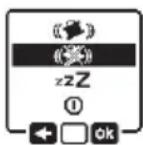
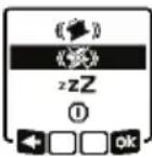
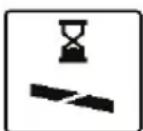
Sleep mode
During breaks from work, you can set the measuring tool to sleep mode. All your settings will still be saved.
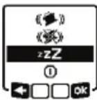
To switch on sleep mode, briefly press the on/off button (11). In the menu which subsequently appears the on/off button (11) as often as required until sleep mode has been selected. Confirm your selection with by pressing the slope button (14).
Alternatively, you can switch on sleep mode by pressing the sleep mode button (28) on the remote control or leveling remote app.
WARNING
Do not switch off sleep mode remotely without
line of sight to the laser tool. The sudden bright laser beam may increase the risk of personal injury or property damage.
Ensure there are no bystanders in the direct path of the laser beam before turning off sleep mode remotely.

When sleep mode is switched on, the sleep mode symbol will be indicated on the display. The status indicator (12) will slowly flash green.
The shock-warning function will remain activated and all settings will be saved.
To switch off sleep mode, briefly press the on/off button (11) on the measuring tool or press the button for sleep mode (28) on the remote control.
You can also switch off the measuring tool while it is in sleep mode by pressing and holding the on/off button (11) for an extended period of time. All other buttons on the measuring tool and the remote control will be deactivated.
It is also possible to switch sleep mode on and off via the Bosch Levelling Remote App.
Locking the keyboard
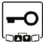
The keyboard of the laser level and the remote control can be locked via the Bosch Leveling Remote App. The keyboard lock indicator will appear on the laser level's display.
The keyboard can be unlocked as follows:
– via the Bosch Leveling Remote App,
- by switching the laser level on and off via the on/off button (11)
- or by pressing the ▲/♂ (4) and ▼/♂ (3) buttons on the measuring tool at the same time.
Operating Modes
Alignment of X and Y-axis
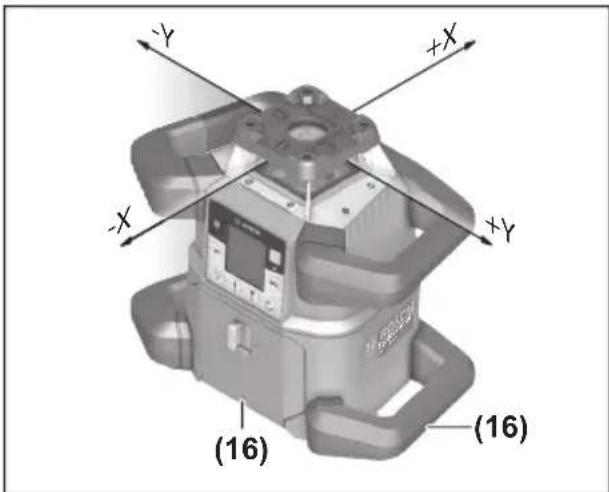
text_image
-Y +X -X -Y -X (16) (16)The alignment of the X and Y axes is marked on the housing above the rotation head. The markings are exactly above the alignment notches (16) at the bottom edge of the housing and on the lower handle. The laser level can be aligned along the axes by using the alignment notches.
Operating modes overview
All three operating modes are possible with the laser level in horizontal and vertical position.

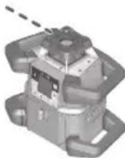
natural_image
3D mechanical component diagram with dashed circular annotation (no text or symbols)Rotational operation
Rotational operation is especially recommended when using the laser receiver. For GRL4000-80CHV it is possible to select between different rotational speeds.
natural_image
Mechanical component diagram showing a piston-like structure with a dashed arrow indicating rotation (no text or symbols present)Line operation (for GRL4000-80CHV only)
In this operating mode, the variable laser beam moves within a defined aperture angle. This increases the visibility of the laser beam in comparison to rotational operation. You can select between different aperture angles.
natural_image
Mechanical component with mounting flanges and a central hub (no visible text or symbols)Point operation (for GRL4000-80CHV only)
In this operating mode, the best visibility of the variable laser beam can be reached. For example, it is used to easily project heights or to check building lines.
Line and point operation are not suitable for use with the laser receiver (42).
Rotational operation (for GRL4000-80CHV)
Each time after switching on, the measuring tool is in rotational operation mode with standard rotational speed (300 min-1).
To switch from line operation to rotational operation, press the rotational operation button (6) or the rotational operation button (27) on the remote control.
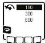
To change the rotational speed, press the rotational operation button (6) or the rotational operation button (27) on the remote control until the required speed is indicated on the display.
The set speed can be seen on the rotational speed indicator (h) on the home screen.
When working with the laser receiver, the highest rotational speed should be set. When not working with the laser receiver, reduce the rotational speed for improved visibility of the laser beam and use the laser goggles (52).
Rotational operation (for GRL4000-80CH)
Each time after switching on, the measuring tool is in rotational operation mode with standard rotational speed (600 min-1). Adjusting the speed for the GRL4000-80CH is not possible.
Line operation/point operation (for GRL4000-80CHV only)
To switch to line or point operation, press the line operation button (5) or the line operation button (29) on the remote control.
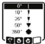
To change the aperture angle, press the line operation button (5) or the line operation button (29) on the remote control until the required operating mode is indicated on the display. The aperture angle is reduced in stages each time a button is pressed until point operation is achieved. Pressing the line operation button again takes you back to line operation via rotational operation at moderate speed.
Note: Due to inertia, it is possible for the laser to slightly move beyond the end point of the laser line.
Functions
Turning the line/point within the rotational plane (for GRL4000-80CHV only)
In line and point operation, the laser line or the laser point can be positioned within the rotational plane of the laser. Rotation is possible by 360°.
To rotate anticlockwise, press the button (4) on the measuring tool or the button for anticlockwise rotation (30) on the remote control.
To rotate clockwise, press the button ⬆ (3) on the measuring tool or the button for clockwise rotation (37) on the remote control.
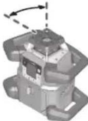
Turning the rotational plane when in the vertical position (for GRL4000-80CHV only)
When the laser level is in the vertical position, it is possible to rotate the laser point, laser line or rotational plane around the Y-axis for easy sighting out or parallel alignment in a range of ±8.5% .
To start the function, press the button for setting the slope (14) on the laser level or the button for setting the slope (32) on the remote control. The indicator for setting the slope of the Y-axis will appear and the symbol for the Y-axis will flash.
To rotate the rotational plane, press the ▲ button (4) or the ▼ button (3) on the measuring tool or the up (31) or down (36) slope button on the remote control until the required position is reached.
Automatic plumb point function in the vertical position (for GRL4000-80CHV only)
When the laser level is in the vertical position, the variable laser beam (8) can automatically be aligned vertically downwards for plumbing by using the remote control or via the Bosch Levelling Remote App.
To start the downwards plumb point function, press the plumb point function button (26) on the remote control. The plumb point function symbol will appear on the display while the variable laser beam is aligned vertically. After it has been successfully aligned, the plumb point function indicator (e) will appear on the start screen.
Note: Possible rotation of the rotational plane around the Y-axis is not in the form of rotation around the plumb point.
Center line mode
In center line mode, the laser level automatically attempts to align the laser beam to the center line of the laser receiver by moving the rotation head up and down. The laser beam can be aligned in relation to the X-axis or the Y-axis of the laser level.
Center line mode is started at the laser receiver. For this, please read and observe the operating instructions for the laser receiver.
During the search, the center line mode indicator for each axis will appear on the display of the laser level tatus display (12) will flash red.
If the laser beam could be aligned to the center line of the laser receiver, the center line mode will automatically finish and the slope found will be indicated on the home screen.
If the laser beam could not be aligned to the center line of the laser receiver, an error message will ap-the display. Before restarting the check the position of the laser level laser receiver.
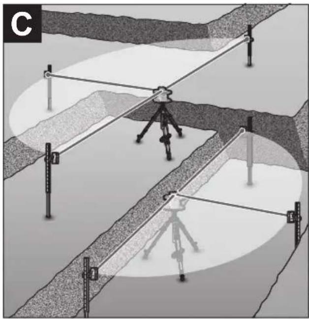
Mask mode (see figure C)
In rotational operation, the variable laser beam (8) can be switched off for one or more quadrants of the rotational plane. This makes it possible to limit the risk related to laser beams to certain areas. Interference from the laser beam that affects other tools or interference with the laser receiver by unintended reflections can also be avoided.
The switching off of individual quadrants can only be controlled by using the Bosch Leveling Remote App. The quadrants in which the laser beam is visible can be seen in the laser operating mode indicator (a) on the home screen.
Automatic leveling
Overview
After switching on, the laser level checks the horizontal and vertical position and automatically levels out any unevenness within the self-leveling range of approx. ±8.5% (approx 5°).
The leveling indicator flashes on the display during leveling. The status display (12) on the laser level and the status display for the respective axis ((35) or (34)) on the remote control flash a uniform green at the same time.
The rotation is stopped until leveling has been completed and the laser beams are flashing. The home screen will appear after leveling has been successfully completed. The laser beams will light up continuously and rotation will start. The status display (12) on the laser level and the status display for the levelled axis ((35) or (34)) on the remote control will light up green continuously.

If the laser level is at a slant of more than 8.5%, leveling will no longer be possible. An error message will appear on the display and the status display (12) will flash red.
Reposition the laser level and wait for it to re-level.
If the maximum leveling time is exceeded, leveling will be discontinued with
an error message.
Reposition the laser level and briefly press the on/off button (11) to restart leveling.
Position changes
When the laser level is levelled in, it continuously checks the horizontal and vertical position. Re-leveling is automatically performed if there are any position changes.
Minimal position changes are levelled out without interrupting the operation. This automatically compensates subsoil ground vibrations or weather influences.
For larger position changes, the rotation of the laser beam will be stopped in order to avoid faulty measurements during the leveling process and the laser beams will flash. The leveling indicator will appear on the display. The shock-warning function will be actuated, if required.
The GRL4000-80CHV will automatically detect the horizontal or vertical position. To change between the horizontal and the vertical position, switch the laser level off, reposition it and switch it on again.
If the position is changed without switching on/off, an error message will appear and the status display (12) will quickly flash red. Briefly press the on/off button (11) to restart leveling.
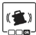
Shock-warning function
The laser level has a shock-warning function. After position changes or shock to the measuring tool, or in case of ground vibrations, it keeps the laser level from levelling in at changed positions, and thus prevents errors caused by a change in the laser level's position.
Activating the shock-warning function:
The shock-warning function is switched on automatically. It is activated approxi-


mately 30 seconds after the laser level has been switched on. During activation, the shock-warning indicator (c) will light up on the display. The indicator lights up continuously after activation.
Shock warning actuated:
If the position of the laser level is changed or a severe knock is registered, the shock warning will be actuated. The laser will stop rotating and an error message will appear. The status display (12) will quickly flash red and a warning signal will sound at a faster rate.
Confirm the warning message with OK by pressing the slope button (14) on the laser level or the slope button (32) on the remote control. When working with automatic levelling (including slope operation), levelling is automatically restarted.
Now check the position of the laser beam at a reference point and, if necessary, correct the height or alignment of the laser level.
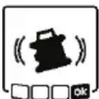
Switching off the shock-warning function:
On the home screen, the current setting is shown with the shock-warning indicator (c):

Shock-warning function is switched on.

Shock-warning function is switched off.
To switch the shock-warning function off or on, briefly press the on/off button (11).
Then press the on/off button (11) in the menu which appears as often as needed until the required setting has been selected. Confirm your selection with OK by pressing the slope button (14).
If the shock-warning function has been switched on, it will be activated after approximately 30 seconds.
Slope operation in the horizontal position
In the laser level's horizontal position, the X-axis and the Y-axis can be tilted independently of each other in a range of ± 8.5% .
To tilt the X-axis, press the slope button (14) on the measuring tool or the slope button
(32) on the remote control once. The menu for setting the slope of the X-axis will appear.
Set the required slope by using the buttons ▲ (4) or ▼ (3) on the measuring tool or using the up (31) or down (36) slope buttons on the remote control. Pressing both slope buttons on the measuring tool or on the remote control at the same time resets the slope back to 0.00%.
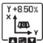
To tilt the Y-axis, press the slope button (14) on the measuring tool or the slope button
(32) on the remote control again. The menu for setting the slope of the Y-axis will appear.
Set the required slope in the same way as outlined for the X-axis.
The required slope is implemented on the measuring tool a few seconds after the last press of a button. The laser beam and the symbol
for setting the slope will flash on the display until the process of setting the slope has been completed.
After the process of setting the slope has been completed, the set slope values of v on the start screen.


(12) on the measuring continuously. The status axes ((35) and/or (34)) uously.
Manual operation
The automatic leveling of the laser level can be switched off (manual operation):
- in the horizontal position for both axes independently of each other,
- in the vertical position for the X-axis (the Y-axis cannot be levelled in the vertical position).
It is possible to set up the laser level at any inclination in the manual operation mode. The axes can also be tilted independently of each other in a range of ±8.5% on the laser level. In manual operating mode, the slope value of an axis will not be shown on the display.
The status indicator (12) on the laser level will light up red continuously if:
- at least one axis is set to manual operating mode in the horizontal position,
- the X-axis is set to manual operating mode in the vertical position.
The Y-axis status display (35) or the X-axis status display (34) on the remote control light up red continuously if the relevant axis is set to manual operating mode.
Manual operation cannot be started via remote control. However, you can change the slope of an axis in exactly the same way using the Slope button up (31) and the Slope button down (36) on the remote control and the buttons ▲ (4) and ▼ (3) on the measuring tool.
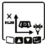
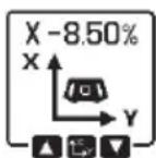
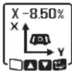
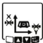
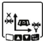
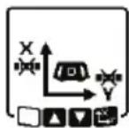
Manual operation in the horizontal position
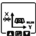
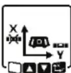
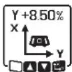
To switch off automatic leveling, press the manual operation button (13) until the required settings combination for both axes is achieved. In the illustrated example, automatic leveling for the X-axis is switched off and the Y-axis continues to be leveled.

text_image
Two identical diagrams showing a vehicle with X and Y axes, each with directional arrows and control icons below.To tilt an axis with automatic levelling switched off, press the slope button (14)
while the menu for manual operating mode is displayed.
If automatic leveling is only switched off for one axis, it will only be possible to change the slope of that axis. When manually operating both axes, it is possible to switch between the axes by pressing the slope button (14) again. The symbol for the axis whose slope can be changed will flash.
Tilt the selected axis using the ▲ (4) or ▼ (3) buttons until the required position is reached.
Manual operation in the vertical position (for GRL4000-80CHV only).
To switch off automatic leveling for the X-axis, press the manual operation button (13) once. (The Y-axis cannot be leveled when in the vertical position.)
To tilt the X-axis without using automatic leveling, press the slope button (14) while manual operating mode is indicated on the display. The symbol for the X-axis will flash on the display.
Tilt the X-axis using the ▲ (4) or ▼ (3) buttons until the required position is reached.
To rotate the Y-axis, press the slope button (14) again while manual operating mode menu is displayed. The symbol for the Y-axis will flash on the display.
Rotate the Y-axis using the ▲ (4) or ▼ (3) buttons until the required position is reached.
Accuracy Check of the Laser level
The following tasks should be performed only by well-trained and qualified persons. The legalities with regard to performing an accuracy check or calibration of a laser level must be known.
Influences on Accuracy
The largest influence is exerted by the ambient temperature. In particular, temperature differences that occur from the ground upwards can refract the laser beam.
Since the temperature stratification is greatest at ground level, you should always mount
the laser level on a tripod for measuring distances of 65.6 ft or more. In addition, position the laser level in the center of the work surface, wherever this is possible.
The deviations have an impact on measuring distances of approx. 65.6 ft (20 m) or more, and at 300 ft (100 m) the deviation can easily be two to four times larger than that at 65.6 ft (20 m).
In addition to external influences, device-specific influences (e.g. falls or heavy impacts) can also lead to deviations. For this reason, check the leveling accuracy each time before beginning work.
If the laser level exceeds the maximum deviation for the measuring procedures described below, perform a calibration (see “Calibrating the laser level”, page 29) or have the laser level checked by a Bosch customer service agent.
Checking the leveling accuracy in a horizontal position
For this check, you will need a free measuring distance of 100 ft on firm ground in front of a wall. You need to complete the entire measurement process for the X and Y-axis respectively.
- Mount the laser level in a horizontal position 100 ft from the wall on a tripod, or place it on a firm, level surface. Switch on the laser level.
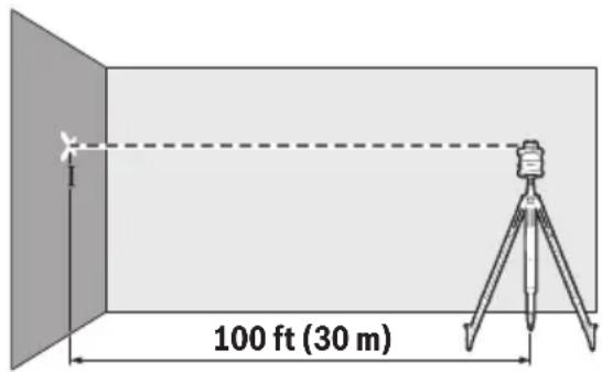
text_image
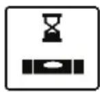
100 ft (30 m)- Once leveling is complete, mark the center of the laser beam on the wall (point I).
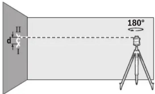
text_image
d II I 180°- Rotate the laser level 180^ without changing its position. Allow it to level in and mark the center point of the laser beam on the wall (point II). Note that point II should preferably be positioned vertically above or below point I.
The discrepancy d between the two marked points I and II on the wall reveals the actual height deviation of the laser level for the axis being measured.
Repeat the measuring process for the other axis. To do this, turn the laser level through 90^ before beginning the measurement.
The maximum permitted deviation on the 100 ft measuring distance is as follows: 100 ft (30 m) is ±1/16 in (±1.5mm). The discrepancy d between points I and II must therefore amount to no more than 1/8 in (3 mm) for each of the two measuring processes.
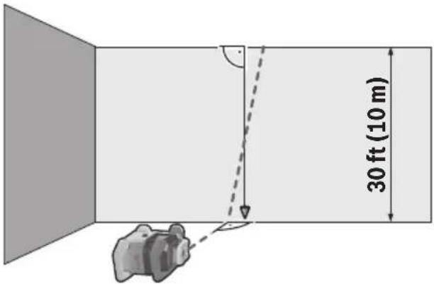
Checking the leveling accuracy in the vertical position (for GRL4000-80CHV only)
For this check, you will need a free measuring distance on firm ground in front of a 30 ft (10 m) tall wall. Fix a plumb line to the wall.
- Position the laser level in the vertical position on a firm, level surface. Switch the laser level on and allow it to level in.
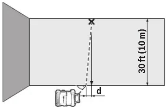
text_image
30 ft (10 m) X d- Set up the laser level so that the laser beam meets the plumb line at the exact center of the upper end. The discrepancy d between the laser beam and the plumb line at the lower end of the line reveals the laser level's deviation from the vertical.
For a 30 ft tall measuring distance, the maximum permitted deviation is as follows: 30 ft (10 m) is ±3/64 in (±1mm). The discrepancy d must therefore be no more than 1 mm.
Calibrating the laser level User Calibration - uCAL
The following tasks should be performed only by well-trained and qualified persons. The legalities with regard to performing an accuracy check or calibration of a laser level must be known.
▶ Perform calibration of the laser level with extreme precision or have the laser level checked by a Bosch customer service agent. Inaccurate calibration leads to incorrect measuring results.
▶ Only start the calibration if you have to perform a calibration of the laser level. As soon as the laser level is in calibration mode, you must perform the calibration meticulously to the end in order to ensure that no incorrect measuring results are produced afterwards.
Check the leveling accuracy after every calibration (see “Accuracy Check of the Laser level”, page 28). If the deviation is outside the maximum permitted limits, have the laser level checked by a Bosch customer service agent.
X-axis and Y-axis Calibration
Calibration is only possible by using the laser receiver LR40. The laser receiver must be connected to the laser level via Bluetooth® (see "Establishing a connection to the remote control/laser receiver", page 22).
The positions of the laser level and laser receiver cannot be changed during calibration (with the exception of the outlined alignments or rotations). The laser level should therefore be placed on a firm, level surface and the laser receiver should be secured to the wall.
Calibration should be performed via the Bosch Leveling Remote App if possible. There is less likelihood of error when controlling the tool via the app. Otherwise, the laser level's position can be altered if buttons are pressed without due care.
For calibration without the app, the buttons on the laser level already outlined must be pressed. It is not possible to operate the laser level via the remote control.
A free measuring distance of 100 ft (30 m) on a firm surface in front of a wall is required. If no such measuring distance is possible, calibration can also be performed with lower measuring accuracy on a measuring distance of 50 ft.
Mount the laser level in the horizontal position 100 ft (30 m) or 50 ft (15 m) from the laser receiver on the tripod (44) or position it on a firm, level surface.
Secure the laser receiver LR40 at the correct height:
- Either to a wall or to another surface by means of magnets or the suspension hooks on the laser receiver,
- or to a securely fastened measuring rod (43) with the holder for the laser receiver.
For this, please observe the operating instructions for the laser receiver.
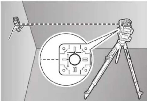
text_image
Diagram illustrating a measurement setup with a tripod-mounted device and an inset close-up of a component, showing alignment and measurement lines.Align the laser level so that the X-axis indicator imprinted on the laser level with the “+” side is pointing to the laser receiver. For this, the X-axis must be perpendicular to the laser receiver.
To start calibration:
- For calibration via the Bosch Levelling Remote App: Switch on the measuring tool. Start calibration in the app. Follow the instructions in the app.
- For calibration without the app: Switch on the measuring tool and the laser receiver. Make sure that both of these are connected via Bluetooth®. Start the calibration by pressing the on/off button on the laser receiver and the center line mode button on the laser receiver at the same time. "CAL" will appear on the display of the laser receiver.
Press the center line mode button on the laser receiver to cancel the calibration, if required.
text_image
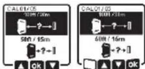
CAL01/05 50Hz / 30m 50Hz / 15m + ? ~] OK CAL01/05 50Hz / 30m 50Hz / 15m + ? ~] OKIn the menu that appears in the measuring tool display after starting the calibration, se-
lect the existing distance between the measuring tool and the laser receiver. To do this, press the buttons ▲ (4) or ▼ (3). Confirm your selection with by pressing the slope button (14).
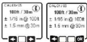
text_image
CAL01/OS 100ft / 30m ± 1/16 in @ 100ft ± 1.5 mm @ 30m CAL01/OS 100ft / 30m ± 1/16 in @ 100ft ± 1.5 mm @ 30mTo confirm the selected measuring distance (b) including the corresponding levelling
accuracy, on the display which appears, press the slope button (14). To go back to selecting the measuring distance (☐), press the line operation button (5).
Align the height of the laser receiver so that the variable laser beam (8) on the laser receiver is indicated as “centered” (see operating instructions for the laser receiver). Secure the laser receiver at this height.
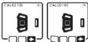
text_image
CAL02/05 CAL02/05Check whether the laser level and laser receiver are aligned with each other, as illustrat-
ed on the display (the “+” side of the X-axis is aligned to the laser receiver). Start the calibration of the X-axis with □ by pressing the slope button (14).

text_image
CAL03/05 180° CAL03/05 180°If this step appears on the display, rotate the laser level 180° so that the “-” side of the
X-axis is aligned to the laser receiver. For each rotation, take care not to change the height and position of the laser level. Confirm the rotation with □ by pressing the slope button (14). Calibration of the X-axis continues.
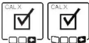
text_image
CALX CALXThe indicator opposite will appear if both sides of the X-axis have been successfully cali-
brated. XOK will appear on the display of the laser receiver.
Continue the calibration with ➞ by pressing the slope button (14).
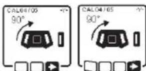
text_image
CAL64705 90° CAL64705 90°To calibrate the Y-axis, rotate the measuring tool 90° in the direc-
that the “+” side of the Y-axis is directed at the laser receiver. Confirm the rotation with □ by pressing the slope button (14).
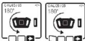
text_image
CAL05/05 180° CAL05/05 180°If this step appears on the display, rotate the measuring tool 180° so that the “-” side of
the Y-axis is aligned to the laser receiver. Confirm the rotation with ▶by pressing the slope button (14). Calibration of the Y-axis continues.
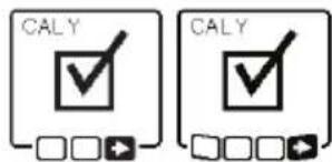
text_image
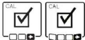
CALY CALYThis symbol will appear on the measuring tool display if the Y-axis has been successfully calibrated. "YOK" will appear on the display of the laser receiver.
Finish the calibration of the Y-axis with ▶ by pressing the slope button (14).
text_image
CAL CALThis symbol confirms that the X-axis and the Y-axis have been successfully calibrated with the levelling accuracy selected at the beginning. End the calibration with ■by pressing the slope button (14).
If the calibration has been completed successfully, the measuring tool then automatically switches itself off.
text_image
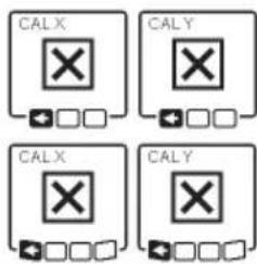
CALX CALY CALX CALYThe relevant error message will appear in the measuring tool display if calibration of the X-axis or the Y-axis has failed. "ERR" will appear on the display of the laser receiver.
Cancel the calibration with ▶ by pressing the button for line operation (5). Check the position of the tool VS receive before restart. Restart the calibration. If calibration fails again, have the measuring tool checked by a Bosch customer service agent.
Z-axis calibration (for GRL4000-80CHV only)
A free measuring distance on firm ground in front of a 30 ft (10 m) wall is required for the calibration. Fix a plumb line to the wall.
text_image
30 ft (10 m)Position the measuring tool on a firm, level surface. Switch the measuring tool on and allow it to level in. Align the measuring tool so that the laser beam is perpendicular to the wall and cuts through the plumb line. Switch the measuring tool off.
To start calibration mode, press and hold the slope button (14) and then also briefly press the on/off button (11). The measuring tool is switched on. Allow the measuring tool to level in.
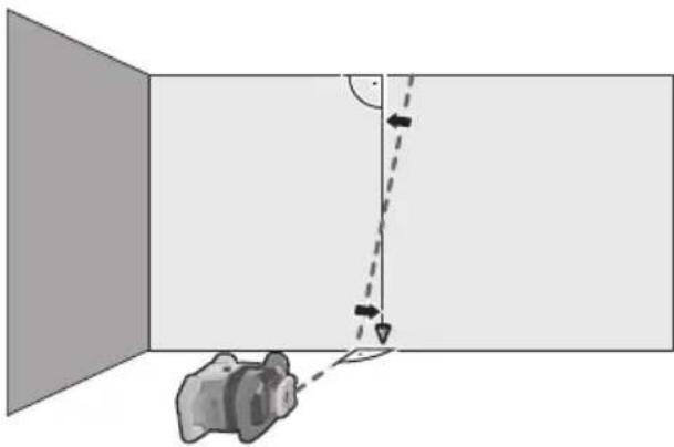
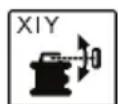
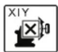
natural_image
Diagram showing a camera in a room with an arrow indicating direction and angle, no text or symbols presentAlign the laser beam so that it runs as parallel as possible to the plumb line. Tilt the laser beam in the ▶ direction by pressing the ▲ button (4). Tilt the laser beam in the ▶ direction by pressing the ▼ button (3).
If it is not possible to align the laser beam in parallel to the plumb line, align the measuring tool to the wall more precisely and start the calibration process again.
If the laser beam is aligned in parallel, save the calibration with OK by pressing the slope button (14).
This symbol confirms that the Z-axis has been calibrated successfully. At the same time, the status indicator (12) will flash green three times. End the calibration with ok by pressing the slope button (14). The device will shut down.
CALZ This error message will appear if calibration of the Z-axis has been unsuccessful. Cancel the calibration with ▼ by pressing the button for line operation (5).
Ensure that the reference vertical line is in the pivoting range of the rotation head and restart the calibration. Make sure that the laser level is not moved during the calibration.
If the calibration is again unsuccessful, have the laser level checked by a Bosch customer service agent.
Working Advice
▶ Only the center of the laser point or laser line must be used for marking. The size of the laser point/the width of the laser line changes depending on the distance.
The laser level is equipped with a wireless interface. Local operating restrictions, e.g. in aeroplanes or hospitals, must be observed.
Working with the Laser Target Plate
The laser target plate (53) improves visibility of the laser beam in unfavorable conditions and at greater distances.
The reflective half of the laser target plate (53) improves visibility of the laser line. The transparent half enables the laser line to be seen from behind the laser target plate.
Working with the Tripod (Accessory)
A tripod offers a stable, height-adjustable support surface for measuring. For horizontal operation, place the laser level with the 5/8" tripod mount (18) on the thread of the tripod (44). Tighten the laser level using the locking screw of the tripod.
For vertical operation, use the 5/8" tripod mount (20).
On a tripod featuring a measuring scale on its extender, you can set the height deviation straight away.
Roughly align the tripod before switching on the laser level.
Laser Goggles (Accessory)
The laser goggles filter out ambient light. This makes the light of the laser appear brighter to the eye.
▶ Do not use the laser goggles as protective goggles. The laser goggles make the laser beam easier to see; they do not protect you against laser radiation.
▶ Do not use the laser goggles as sunglasses or while driving. The laser goggles do not provide full UV protection and impair your ability to see colors.
Working with a wall mount and alignment unit (see figure D)
The laser level can be secured to the wall using the wall mount with the alignment unit (45). Using the wall mount is recommended, e.g. when working above the maximum extension height of tripods, or when working on unstable surfaces without a tripod.
Fasten the wall mount (45) either to a wall using screws through the fixing holes (47) or to a strip of wall using the fastening screw. (46) Fit the wall mount as perpendicular as possible to the wall and ensure it is mounted in a stable way.
Screw the 5/8" wall mount screw (50) into the horizontal tripod mount (18), depending on the requirements of the task, or the vertical tripod mount (20) on the laser level.
Using the alignment unit allows the laser level to be moved in a range of approx. 13 cm with respect to height. Press the button (48) and move the alignment unit to roughly the required height. It is possible to align the laser beam precisely to a reference height using the fine adjustment screw (49).
Working with the measuring rod (accessory) (see figure E)
To check levels or apply slopes, it is recommended to use the measuring rod (43) together with the laser receiver.
A relative measuring scale is incorporated at the top of the measuring rod (43). You can preselect its zero at the bottom on the extender. This enables you to read deviations from the target height straight away.
Example applications
Projecting/checking heights (see figure F)
Position the laser level in the horizontal position on a firm support or mount it on a tripod (44) (accessory).
Working with a tripod: Set the laser beam at the required height. Project or check the height at the target location.
Working without a tripod: Determine the height difference between the laser beam and the height at the reference point using the laser target plate (53). Project or check the height difference measured at the target location.
Parallel alignment of a plumb beam/projecting right angles (see figure F)
When right angles are to be projected or partition walls are to be aligned, the plumb beam (10) must be aligned in parallel, meaning at the same distance to a reference line (e.g. a wall).
For this, set up the laser level in the vertical position and position it in such a manner that the plumb beam runs approximately parallel to the reference line.
For the exact positioning, measure the clearance between the plumb beam and reference line directly on the laser level using the laser target plate (53). Measure the clearance between the plumb beam and reference line again as far away as possible from the laser level. Align the plumb beam in such a manner that it has the same clearance to the reference line as when measured directly at the laser level.
The right angle to the plumb beam (10) is indicated by the variable laser beam (8).
Indicating a perpendicular/vertical plane (see figure G)
To indicate a perpendicular or a vertical plane, set up the laser level in the vertical position. When the vertical plane is supposed to run at a right angle to a reference line (e.g. a wall), align the plumb beam (10) with this reference line.
The perpendicular plane is indicated by the variable laser beam (8).
Aligning a perpendicular/vertical plane (see figure H)
To align the vertical laser line or the rotational plane against a reference point on a wall, set up the laser level in the vertical position, and roughly align the laser line or the rotational plane with the reference point. For precise alignment with the reference point, turn the rotational plane around the Y-axis (see “Turning the rotational plane when in the vertical position”, page 25).
Working without the laser receiver
Under favorable light conditions (dark environment) and for short distances, it is possible to work without the laser receiver. For improved visibility of the laser beam, either select line operation or point operation and rotate the laser beam to the target location.
Working with the laser receiver (see figure E)
In unfavorable lighting conditions (bright environment, direct sunlight) and for larger distances, use the laser receiver to improve detection of the laser beam (42). When working with the laser receiver, select rotational operation with the highest rotational speed.
Working outdoors (see figure E)
The laser receiver (42) should always be used when working outdoors.
When working on unstable ground, mount the laser level on the tripod (44). Always work with the shock-warning function activated in order to avoid faulty measurements in case of ground movements or shocks to the laser level.
Setting up formwork (see figure I)
Mount the laser level in the horizontal position on a tripod (44) and set up the tripod outside the formwork area. Select rotational operation.
Secure the laser receiver (42) to a measuring rod (43) with the holder. Position the measuring rod on a reference point for the formwork.
Align the height of the laser receiver on the measuring rod so that the variable laser beam (8) of the laser level is indicated as “centered” (see operating instructions for the laser receiver).
Then position the measuring rod with the laser receiver, one after the other, at different test locations on the formwork. Make sure that the laser receiver remains in the same position on the measuring rod.
Correct the height of the formwork until the laser beam is indicated as “centered” at all test locations.
Checking slopes (see figure J)
Mount the laser level in the horizontal position on a tripod (44). Select rotational operation.
Set up the tripod with the laser level so that the X-axis is aligned with the slope that is to be checked.
Position the target slope as the slope for the X-axis (see “Slope operation in the horizontal position”, page 26).
Secure the laser receiver (42) to a measuring rod (43) with the holder. Place the measuring rod at the base of the slope surface.
Align the height of the laser receiver on the measuring rod so that the variable laser beam (8) of the laser level is indicated as “centered” (see operating instructions for the laser receiver).
Then position the measuring rod with the laser receiver, one after the other, at different test locations on the slope surface. Make sure that the laser receiver remains in the same position on the measuring rod.
If the slope of the plane is correct, the laser beam will be indicated as “centered” at all test locations.
Overview of status indicators
Measuring tool Function

Green Red
Horizontal position: X- or Y-axis levelling process.
Vertical position: X-axis levelling process.
Sleep mode activated.
● Horizontal position: Both axes are levelled.
Vertical position: X-axis is levelled.
- automatic shut-down due to error message (e.g. empty rechargeable/non-rechargeable battery, operating temperature exceeded).
Centre line mode started (see operating instructions for the laser receiver).
- Position of the measuring tool changed without switching on/off.
Self-levelling not possible, end of the self-levelling range.
- Shock-warning function actuated.
○ Measuring tool is being calibrated.
● Horizontal position: At least one axis is tilted or is in manual operating mode.
Vertical position: X-axis is tilted or in manual operating mode.
● lighting up continuously
○ flashing
| Remote controlX | Remote controlY | Function |
| Green Red Green Red | ||
| ○ X-axis levelling process (horizontal and vertical positions). | ||
| ○ Y-axis levelling process (horizontal position). | ||
| ○ ○ Remote control is connected via Bluetooth®. | (Both of the status indicators flash alternately.) | |
| ● | ● | Remote control successfully connected via Bluetooth®. |
| ● | X-axis is levelled in (horizontal and vertical positions). | |
| ● | Y-axis is levelled in (horizontal position). | |
| ● | X-axis is tilted or in manual operating mode (horizontal and vertical positions). | |
| ● Y-axis is tilted or in manual operating mode (horizontal position). | ||
| ● | ● Unsuccessful connection to the measuring tool via Bluetooth®. | |
● lighting up continuously
- flashing
Overview of control options for the functions
| Function GRL4000-80CH GRL4000-80CHV RC5 LR40 Bosch Leveling | |||||
| Remote App | |||||
| Switching on/off ● ● —— | |||||
| Establish connection via Bluetooth® A) | ● ● ● ● ● | ||||
| Sleep mode —— ● — ● | |||||
| Switch on the keyboard lock | — | — | — | — | ● |
| Switch off the keyboard lock | ● ● —— | ● | |||
| Rotation operation | ● ● ● — | ● | |||
| Line and point operation | — | ● | ● | — | ● |
| Turning the line/point within the rotational plane | — | ● ● — | ● | ||
| Turning the rotational plane when in the vertical position | — | ● ● — | ● | ||
| Automatic plumb point function in the vertical position | —● — | ● | |||
| Center line mode —— — ● | — | ||||
| Partial projection | — | — | — | — | ● |
| Shock-warning function | ● ● —— | ● | |||
| Inclination operation | ● ● ● — | ● | |||
| Manual operation | ● ● —— | ● | |||
| X-axis and Y-axis calibration (horizontal position) B) | ● ● — ● ● | ||||
| Z-axis calibration (vertical position) | — | ● | — | — | ● |
A) The function must be started on both the laser level and the remote control, laser receiver or smart phone at the same time.
B) The function must be started on both the measuring tool and the smartphone at the same time or on the laser receiver.
Rectifying errors
| Rotary laser display indicator | Laser receiver display indicator | Problem Corrective measure | |
 | - Adjust the laser temperature be- (operating temperature exceeded) | before switching it on. Then check the measuring accuracy and calibrate the laser level if required. | |
 | - Automatic shut-down (empty batteries or rechargeable battery) | Change the batteries or the rechargeable battery. | |
 | -/PNK | Unsuccessful attempt to connect to the remote control (41) or the laser receiver Z | Briefly press the on/off button (11). Start the connection process again (see "Establishing a connection to the re- mote control/laser receiver", page 22). If it is not possible to establish a connection, please con- tact a Bosch customer service agent. |
 | - Unsuccessful attempt to connect to the mobile device | Briefly press the on/off button (11). Start the connection process again (see "Remote control via the Bosch Level- ing Remote App", page 22). If it is not possible to establish a connection, please con- tact a Bosch customer service agent. | |
 | - Measuring tool is at a slant of more than 8.5% or is not in the correct horizontal or vertical position. | Reposition the laser level. Make sure that it is in the correct position. The re-leveling will start automatically. | |
 | - Maximum levelling time is exceeded. | Reposition the laser level. Make sure that it is in the correct position. Briefly press the on/off button (11) to restart levelling. | |
 | - Change between the hori- zonal and vertical position without switching the measuring tool on/off | Briefly press the on/off button (11) to restart levelling. | |
 | ERR | Unsuccessful calibration of the X-axis | Cancel the calibration with by pressing the button for line operation (5). Check that the laser level and the receiver are aligned correctly and restart the calibration. |
 | ERR | Unsuccessful calibration of the Y-axis | Cancel the calibration with by pressing the button for line operation (5). Check that the laser level and the receiver are aligned correctly and restart the calibration. |
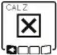 | - Unsuccessful calibration of the Z-axis | Cancel the calibration with by pressing the button for line operation (5). Check that the laser level is aligned correctly and restart calibration. | |
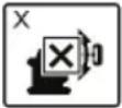 | ERR | Unsuccessful centre line mode in relation to the X-axis | Press any button to terminate the function. Before re- starting the function, check the position of the laser level and the laser receiver. |
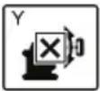 | ERR | Unsuccessful centre line mode in relation to the Y-axis | Press any button to terminate the function. Before re- starting the function, check the position of the laser level and the laser receiver. |
Maintenance and Service

Store and transport the tool only in the supplied
protective case.
Check the tool each time before using.
Keep the tool clean and dry at all times to ensure proper and safe operation.
Do not immerse the tool into water or other fluids.
Wipe off debris using a moist and soft cloth. Do not use any cleaning agents or solvents.
Regularly clean the surfaces at the exit opening of the laser.
In case of visible damage or loose components in the interior of the tool, the safe function is no longer ensured.
If the tool should fail despite the care taken in manufacturing and testing
procedures, repair should be carried out by an authorized after-sales service center for Bosch power tools.
In all correspondence and spare parts orders, please always include the 10-digit article number given on the type plate of the tool.
In case of repairs, send in the tool packed in its protective case.
ENVIRONMENT PROTECTION
Recycle raw materials & batteries instead of disposing of waste. The unit, accessories, packaging & used batteries should be sorted for
environmentally friendly recycling in accordance with the latest regulations.
LIMITED WARRANTY OF BOSCH LASER AND Laser level PRODUCTS
Robert Bosch Tool Corporation (“Seller”) warrants to the original purchaser only, that all Bosch lasers and laser levels will be free from defects in material or workmanship for a period of one (1) year from date of purchase. Bosch will extend warranty coverage to two (2) years when you register your product within eight (8) weeks after date of purchase. Product registration card must be complete and mailed to Bosch (postmarked within eight weeks after date of purchase), or you may register on-line at www.boschtools.com/Service/ProductRegistration. If you choose not to register your product, a one (1) year limited warranty will apply to your product.
30 Day Money Back Refund or Replacement -
If you are not completely satisfied with the performance of your laser and laser levels, for any reason, you can return it to your Bosch dealer within 30 days of the date of purchase for a full refund or replacement. To obtain this 30-Day Refund or Replacement, your return must be accompanied by the original receipt for purchase of the laser or optical instrument product. A maximum of 2 returns per customer will be permitted.
SELLER'S SOLE OBLIGATION AND YOUR EXCLUSIVE REMEDY under this Limited Warranty and, to the extent permitted by law, any warranty or condition implied by law, shall be the repair or replacement of parts, without charge, which are defective in material or workmanship and which have not been misused, carelessly handled, or misrepaired by persons other than Seller or Authorized Service Center. To make a claim under this Limited Warranty, you must return the complete Bosch laser or laser level, transportation prepaid, to any BOSCH Factory Service Center or Authorized Service Center. Please include a dated proof of purchase with your tool. For locations of nearby service centers, please use our on-line service locator or call 1-877-267-2499.
THIS WARRANTY PROGRAM DOES NOT APPLY TO TRIPODS AND RODS. Robert Bosch Tool Corporation (“Seller”) warrants tripods and leveling rods for a period of one (1) year from date of purchase.
THIS LIMITED WARRANTY DOES NOT APPLY TO OTHER ACCESSORY ITEMS AND RELATED ITEMS. THESE ITEMS RECEIVE A 90 DAY LIMITED WARRANTY.
To make a claim under this Limited Warranty, you must return the complete product, transportation prepaid. For details to make a claim under this Limited Warranty please visit www.boschtools.com or call 1-877-267-2499.
ANY IMPLIED WARRANTIES SHALL BE LIMITED IN DURATION TO ONE YEAR FROM DATE OF PURCHASE. SOME STATES IN THE U.S., AND SOME CANADIAN PROVINCES DO NOT ALLOW LIMITATIONS ON HOW LONG AN IMPLIED WARRANTY LASTS, SO THE ABOVE LIMITATION MAY NOT APPLY TO YOU.
IN NO EVENT SHALL SELLER BE LIABLE FOR ANY INCIDENTAL OR CONSEQUENTIAL DAMAGES (INCLUDING BUT NOT LIMITED TO LIABILITY FOR LOSS OF PROFITS) ARISING FROM THE SALE OR USE OF THIS PRODUCT. SOME STATES IN THE U.S., AND SOME CANADIAN PROVINCES DO NOT ALLOW THE EXCLUSION OR LIMITATION OF INCIDENTAL OR CONSEQUENTIAL DAMAGES, SO THE ABOVE LIMITATION MAY NOT APPLY TO YOU.
THIS LIMITED WARRANTY GIVES YOU SPECIFIC LEGAL RIGHTS, AND YOU MAY ALSO HAVE OTHER RIGHTS WHICH VARY FROM STATE TO STATE IN THE U.S., OR PROVINCE TO PROVINCE IN CANADA AND FROM COUNTRY TO COUNTRY.
THIS LIMITED WARRANTY APPLIES ONLY TO PRODUCTS SOLD WITHIN THE UNITED STATES OF AMERICA, CANADA AND THE COMMONWEALTH OF PUERTO RICO. FOR WARRANTY COVERAGE WITHIN OTHER COUNTRIES, CONTACT YOUR LOCAL BOSCH DEALER OR IMPORTER.