ST1520E-S - Lawn mower EGO - Free user manual and instructions
Find the device manual for free ST1520E-S EGO in PDF.


User questions about ST1520E-S EGO
0 question about this device. Answer the ones you know or ask your own.
Ask a new question about this device
Download the instructions for your Lawn mower in PDF format for free! Find your manual ST1520E-S - EGO and take your electronic device back in hand. On this page are published all the documents necessary for the use of your device. ST1520E-S by EGO.
USER MANUAL ST1520E-S EGO
natural_image
Line drawing of a mechanical device with articulated arms and connectors (no text or symbols)OPERATOR'S MANUAL
56 VOLT LITHIUM-ION CORDLESS LINE TRIMMER
MODEL NUMBER ST1520E-S
text_image
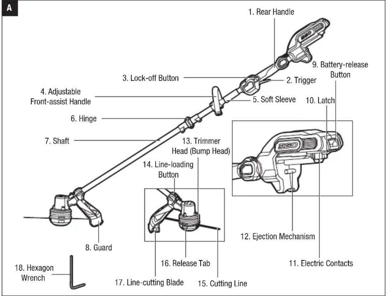
A 1. Rear Handle 2. Trigger 3. Lock-off Button 4. Adjustable Front-assist Handle 5. Soft Sleeve 6. Hinge 7. Shaft 8. Guard 9. Battery-release Button 10. Latch 11. Electric Contacts 12. Ejection Mechanism 13. Trimmer Head (Bump Head) 14. Line-loading Button 15. Cutting Line 16. Release Tab 17. Line-cutting Blade 18. Hexagon Wrench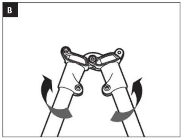
natural_image
Diagram of a mechanical linkage mechanism with rotating arrows indicating motion (no text or symbols)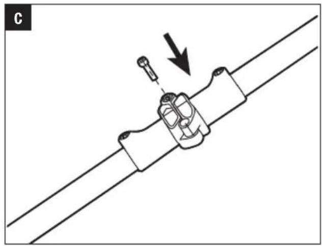
natural_image
Mechanical assembly diagram showing a clamp or bracket being inserted into a cable with a screw, indicated by an arrow (no text or symbols present)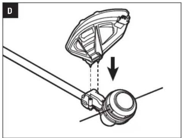
natural_image
Mechanical assembly diagram showing a bracket and connecting rod with a gear mechanism, no text or symbols present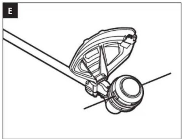
natural_image
Technical line drawing of a mechanical assembly with no visible text or symbols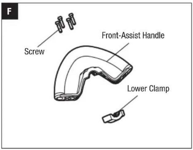
text_image
F Screw Front-Assist Handle Lower Clamp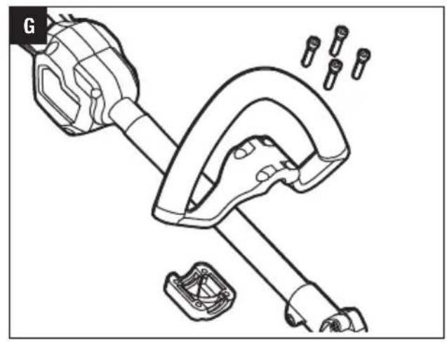
natural_image
Technical line drawing of a mechanical device with multiple components and fasteners (no text or symbols)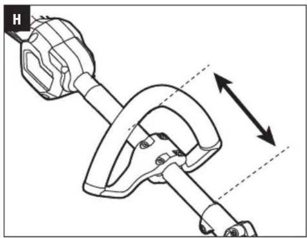
natural_image
Technical line drawing of a mechanical clamp or bracket assembly with directional arrows indicating motion (no text or symbols)
text_image
11 Backpack Line Battery Pack Adaptor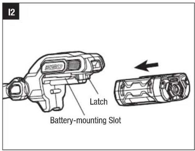
text_image
12 Latch Battery-mounting Slot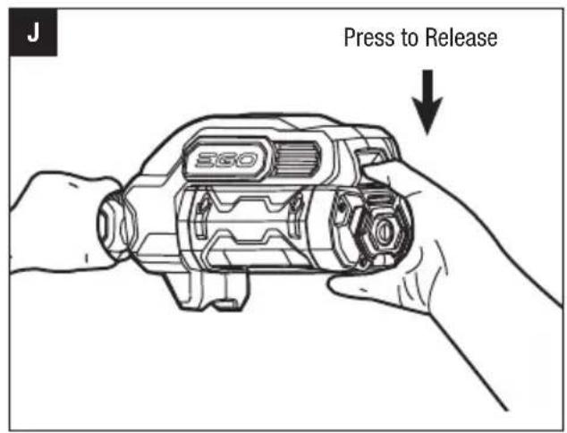
text_image
Press to Release EGO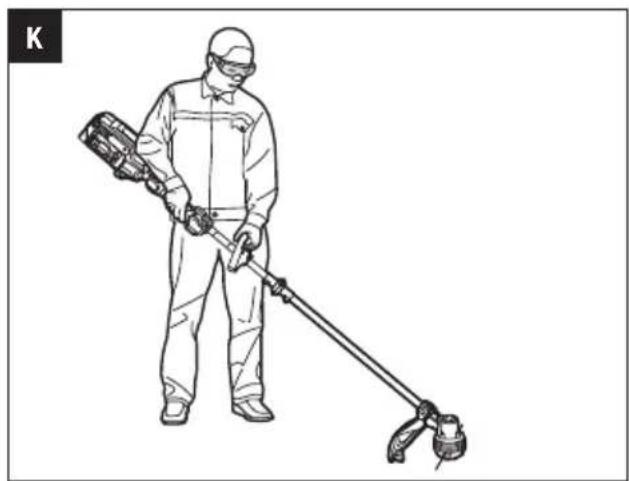
natural_image
Line drawing of a person in protective gear using a handheld tool (no text or symbols)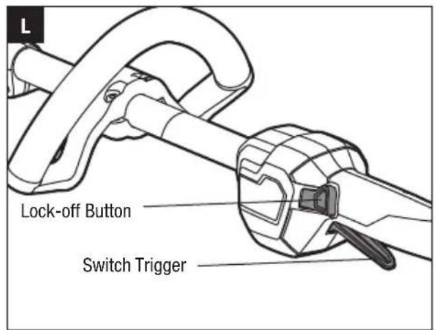
text_image
Lock-off Button Switch Trigger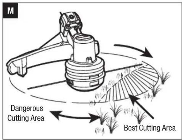
text_image
M Dangerous Cutting Area Best Cutting Area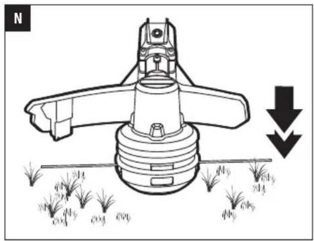
text_image
Cutting Line Lower Cover Eyelet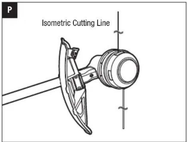
text_image
Isometric Cutting Line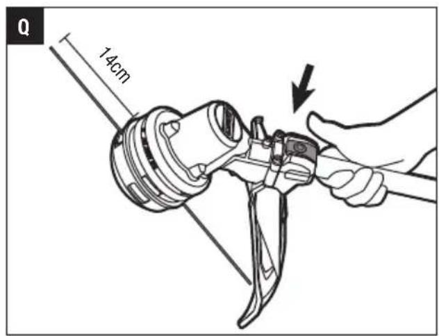
text_image
Q 14cm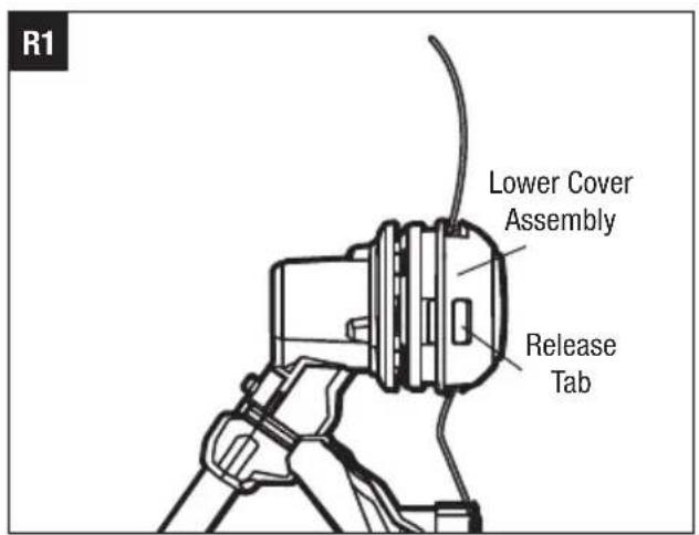
text_image
R1 Lower Cover Assembly Release Tab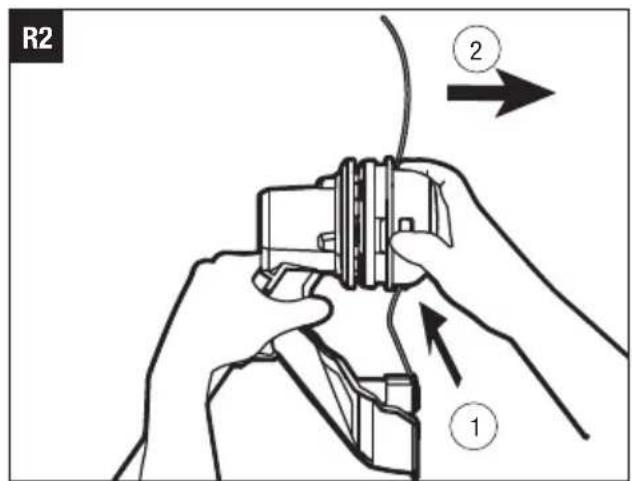
text_image
R2 ② ①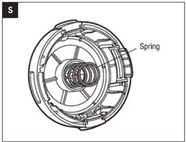
text_image
Spring
text_image
Release Tab Slot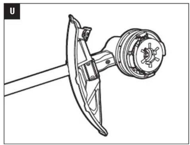
natural_image
Technical line drawing of a mechanical assembly with a central component and a shaft (no text or symbols)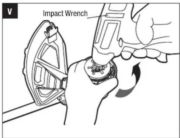
text_image
Impact Wrench
text_image
W Upper Cover Spool Assembly Washer Nut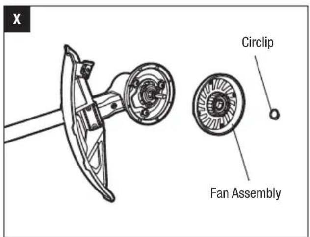
text_image
X Circlip Fan Assembly
text_image
Y Spline Key SlotEN
READ ALL INSTRUCTIONS!

READ OPERATOR'S MANUAL
WARNING: To ensure safety and reliability, all repairs and replacements should be performed by a qualified service technician.
SAFETY SYMBOLS
The purpose of safety symbols is to attract your attention to possible dangers. The safety symbols and the explanations with them deserve your careful attention and understanding. The symbol warnings do not, by themselves, eliminate any danger. The instructions and warnings they give are no substitutes for proper accident prevention measures.
WARNING: Be sure to read and understand all safety instructions in this Operator's Manual, including all safety alert symbols such as "DANGER," "WARNING," and "CAUTION" before using this tool. Failure to follow all instructions listed below may result in electric shock, fire, and/or serious personal injury.
SYMBOL MEANING
SAFETY ALERT SYMBOL: Indicates DANGER, WARNING, or CAUTION, may be used in conjunction with other symbols or pictographs.
SAFETY INSTRUCTIONS
This page depicts and describes safety symbols that may appear on this product. Read, understand, and follow all instructions on the machine before attempting to assemble and operate it.
| Safety Alert | Indicates a potential personal injury hazard. | |
| Read Operator's Manual | To reduce the risk of injury, user must read and understand the operator's manual before using this product. | |
| Wear Eye Protection | Always wear safety goggles or safety glasses with side shields and a full face shield when operating this product. | |
| Wear hearing protection | Always wear ear protection when operating this product. |
| No Cutting Blade | Do not install metal or plastic cutting blades | |
| Ricochet and Keep Bystanders Away | Thrown objects can ricochet and result in personal injury or property damage. Ensure that other people and pets remain away from the line trimmer when it is in use. | |
| Keep By-standers Away | Ensure that other people and pets remain at least 15m away from the line trimmer when it is in use. | |
| Noise Sound | pressure level | |
| IPX4 | Ingress Protection Degree | Protection from splashing water |
| V Volt | Voltage | |
| Direct Current | Type or a characteristic of current | |
| n_0 | No Load Speed | Rotational speed, at no load |
| ... /min | Per Minute Revolutions per minute | |
| mm millimeter Length or size | ||
| cm Centimeter Length or size | ||
 | No Cutting Blade | Do not install metal or plastic cutting blades |
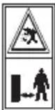 | Ricochet and Keep Bystanders Away | Thrown objects can ricochet and result in personal injury or property damage. Ensure that other people and pets remain away from the line trimmer when it is in use. |
 | Keep By-standers Away | Ensure that other people and pets remain at least 15m away from the line trimmer when it is in use. |
 | Noise Sound | pressure level |
| IPX4 | Ingress Protection Degree | Protection from splashing water |
| V Volt | Voltage | |
| [7xcy] | Direct Current | Type or a characteristic of current |
| [###] | No Load Speed | Rotational speed, at no load |
| ... /min | Per Minute Revolutions per minute | |
| mm millimeter Length or size | ||
| cm Centimeter Length or size | ||
GENERAL POWER TOOL SAFETY WARNINGS
WARNING: Read all safety warnings, instructions, illustrations and specifications provided with this power tool. Failure to follow all instructions listed below may result in electric shock, fire and/or serious injury.
Save all warnings and instructions for future reference.
The term “power tool” in the warnings refers to your mains-operated (corded) power tool or battery-operated (cordless) power tool.
WORK AREA SAFETY
- Keep work area clean and well lit. Cluttered or dark areas invite accidents.
■ Do not operate power tools in explosive atmospheres, such as in the presence of flammable liquids, gases or dust. Power tools create sparks which may ignite the dust or fumes. - Keep children and bystanders away while operating a power tool. Distractions can cause you to lose control.
ELECTRICAL SAFETY
■ Power tool plugs must match the outlet. Never modify the plug in any way. Do not use any adaptor plugs with earthed (grounded) power tools. Unmodified plugs and matching outlets will reduce risk of electric shock
■ Avoid body contact with earthed or grounded surfaces, such as pipes, radiators, ranges and refrigerators. There is an increased risk of electric shock if your body is earthed or grounded.
■ Do not expose power tools to rain or wet conditions. Water entering a power tool will increase the risk of electric shock.
- Do not abuse the cord. Never use the cord for carrying, pulling or unplugging the power tool. Keep cord away from heat, oil, sharp edges or moving parts. Damaged or entangled cords increase the risk of electric shock.
- When operating a power tool outdoors, use an extension cord suitable for outdoor use. Use of a cord suitable for outdoor use reduces the risk of electric shock.
■ If operating a power tool in a damp location is unavoidable, use a residual current device (RCD) protected supply. Use of an RCD reduces the risk of electric shock.
PERSONAL SAFETY
- Stay alert, watch what you are doing and use common sense when operating a power tool. Do not use a power tool while you are tired or under the influence of drugs, alcohol medication. A moment of inattention while operating power tools may result in serious personal injury.
■ Use personal protective equipment. Always wear eye protection. Protective equipment such as a dust mask, non-skid safety shoes, hard hat, or hearing protection used for appropriate conditions will reduce personal injuries.
■ Prevent unintentional starting. Ensure the switch is in the off-position before connecting to power source and/or battery pack, picking up or carrying the tool. Carrying power tools with your finger on the switch or energising power tools that have the switch on invites accidents.
■ Remove any adjusting key or wrench before turning the power tool on. A wrench or a key left attached to a rotating part of the power tool may result in personal injury.
■ Do not overreach. Keep proper footing and balance at all times. This enables better control of the power tool in unexpected situations.
■ Dress properly. Do not wear loose clothing or jewelry. Keep your hair, clothing and gloves away from moving parts. Loose clothes, jewelry or long hair can be caught in moving parts.
■ If devices are provided for the connection of dust extraction and collection facilities, ensure these are connected and properly used. Use of dust devices can reduce dust-related hazards.
■ Recommendation that the tool always be supplied via a residual current device having a rated residual current of 30 mA or less.
■ Do not let familiarity gained from frequent use of tools allow you to become complacent and ignore tool safety principles. A careless action can cause severe injury within a fraction of a second.
POWER TOOL USE AND CARE
■ Do not force the power tool. Use the correct power tool for your application. The correct power tool will do the job better and safer at the rate for which it was designed.
■ Do not use the power tool if the switch does not turn it on and off. Any power tool that cannot be controlled with the switch is dangerous and must be repaired.
■ Disconnect the plug from the power source and/or the battery pack from the power tool before making any adjustments, changing accessories, or storing power tools. Such preventive safety measures reduce the risk of starting the power tool accidentally.
■ Store idle power tools out of the reach of children and do not allow persons unfamiliar with the power tool or these instructions to operate the power tool. Power tools are dangerous in the hands of untrained users.
EN
- Maintain power tools and accessories. Check for misalignment or binding of moving parts, breakage of parts and any other condition that may affect the power tool's operation. If damaged, have the power tool repaired before use. Many accidents are caused by poorly maintained power tools.
- Keep cutting tools sharp and clean. Properly maintained cutting tools with sharp cutting edges are less likely to bind and are easier to control.
■ Use the power tool, accessories and tool bits in accordance with these instructions, taking into account the working conditions and the work to be performed. Use of the power tool for operations different from those intended could result in a hazardous situation.
- Keep handles and grasping surface dry, clean and free from oil and grease. Slippery handles and grasping surfaces do not allow for safe handling and control of the tool in unexpected situations.
BATTERY TOOL USE AND CARE
■ Recharge only with the charger specified by the manufacturer. A charger that is suitable for one type of battery pack may create a risk of fire when used with another battery pack.
■ Use power tools only with specifically designated battery packs. Use of any other battery packs may create a risk of injury and fire.
- When battery pack is not in use, keep it away from OPERATION
other metal objects, like paper clips, coins, keys, nails, screws or other small metal objects, that can make a connection from one terminal to another.
- Use the line
- Never
Shorting the battery terminals together may cause burns or a fire.
■ Under abusive conditions, liquid may be ejected from the battery; avoid contact. If contact accidentally occurs, flush with water. If liquid contacts eyes, additionally seek medical help.
Liquid ejected from the battery may cause irritation or burns.
■ Do not use a battery pack or tool that is damaged or modified. Damaged or modified batteries may exhibit unpredictable behaviour resulting in fire, explosion or risk of injury.
■ Do not expose a battery pack or tool to fire or excessive temperature. Exposure to fire or temperature above 100 °C may cause explosion.
■ Follow all charging instructions and do not charge the battery pack or tool outside the temperature range specified in the instructions. Charging
improperly or at temperatures outside the specified range may damage the battery and increase the risk of fire.
SERVICE
■ Have your power tool serviced by a qualified repair person using only identical replacement parts.
This will ensure that the safety of the power tool is maintained.
■ Never service damaged battery packs. Service of battery packs should only be performed by the manufacturer or authorised service providers.
TRAINING
- Read the instructions carefully. Be familiar with the controls and the proper use of the machine.
■ Never allow people unfamiliar with these instructions or children to use the machine. Local regulations can restrict the age of the operator. - Keep in mind that the operator or user is responsible for accidents or hazards occurring to other people or their property.
PREPARATION
■ Never operate this product while people, especially children, or pets are nearby.
■ Wear eye protection and stout shoes at all times while operating this product.
■ The distance between the machine and bystanders shall be at least 15m.
■ Use the line trimmer only in daylight or good artificial light.
■ Never operate the line trimmer with damaged guards or shields or without guards or shields in place.
■ Switch on the motor only when the hands and feet are away from the cutting means.
■ Always disconnect the line trimmer from the power supply (i.e. remove the battery pack).
■ whenever leaving the line trimmer unattended;
■ before clearing a blockage;
■ before checking, cleaning or working on the line trimmer;
■ after striking a foreign object;
■ whenever the line trimmer starts vibrating abnormally.
■ Take care against injury to feet and hands from the cutting means.
■ Always ensure that the ventilation openings are kept clear of debris.
MAINTENANCE AND STORAGE
■ Disconnect the power supply from the line trimmer (i.e. remove the battery pack) before carrying out maintenance or cleaning work.
- Use only the manufacturer's recommended replacement parts and accessories.
- Inspect and maintain the line trimmer regularly. Have the machine repaired only by an authorised repairer.
■ When not in use, store the line trimmer out of the reach of children.
OTHER SAFETY WARNINGS
- Avoid dangerous environments - Don't use appliances on damp or wet slope.
- Keep guards in place and in working order.
- Keep hands and feet away from the cutting area.
- Store line trimmer indoors - When not in use the line trimmer should be stored indoors in a dry and high or locked-up place with the battery pack removed-out of reach of children.
■ Before using the line trimmer and after any impact check for signs of wear or damage and repair as necessary.
SAVE THESE INSTRUCTIONS!
SPECIFICATIONS
■ If the equipment should start to vibrate abnormally, stop the motor, remove the battery pack from the line trimmer and check immediately for the cause.
SAVE THESE INSTRUCTIONS!
Vibration is generally a warning of trouble. A loose cutting unit may vibrate, crack, break or come off the line trimmer, which may result in serious or fatal injury. Make sure that the cutting unit is properly installed and securely fastened. If the cutting unit loosens after fixing it in position, replace it immediately. Never use a line trimmer with a loose cutting unit.
■ To reduce the risk of injury, never work on a ladde or on any other insecure support. Never hold the cutting unit above waist height.
- Check the cutting unit at regular short intervals during operation, or immediately if there is a noticeable change in cutting behavior.
- For best results, your battery should be charged in a location where the temperature is greater than 5°C and less than 40°C. Do not store it outside or in vehicles.
■ Only use EGO authorised polymer trimmer line and blade accessories, trimmer line and blade that are designed for use with this line trimmer. Although certain unauthorised units might be extremely dangerous, and/or damaging to the tools.
■ If you are approached, stop the motor and cutting uni
■ A coasting blade/line can cause injury while it continues to spin after the motor is stopped or trigger is released. Maintain proper control until the blade/line has completely stopped rotating.
- Use only with EGO's battery packs and chargers list below:
| BATTERY | CHARGER |
| BA1120E, BA1400, BA2240E, BA2800, BA3360, BA4200 | CH5500E, CH2100E |
■ Battery tools do not have to be plugged into an electrical outlet; therefore, they are always in operating condition. Be aware of possible hazards even when the tool is not operating. Take care when performing maintenance or service.
■ Do not wash with a hose; avoid getting water in motor and electrical connections.
■ If situations occur that are not covered in this manual, use care and good judgment. Contact the EGO Customer Service Center for assistance.
SPECIFICATIONS
| Voltage | 56V --- |
| No-load Speed 4000-5800/min | |
| Cutting Mechanism Bump Head | |
| Cutting Line Type | 2.4mm nylon twist line |
| Cutting Width 38cm | |
| Recommended Operating Temperature | 0°C-40°C |
| Recommended Storage Temperature | -20°C-70°C |
| Weight (without battery pack) | 3.2kg |
| Guaranteed sound power level 67dB(A) |
PACKING LIST
| PART NAME QUANTITY | |
| Line Trimmer 1 | |
| Guard 1 | |
| Front-assist Handle Assembly 1 | |
| Bolt 1 | |
| Hex Wrench | 1 |
| Operator's Manual | 1 |
EN
DESCRIPTION
KNOW YOUR LINE TRIMMER (Fig. A)
- Rear Handle
- Switch Trigger
- Lock-off Button
- Adjustable Front-assist Handle
- Soft Sleeve
- Hinge
- Shaft
- Guard
- Battery-release Button
- Latch
- Electric Contacts
- Ejection Mechanism
- Trimmer Head (Bump Head)
- Line-loading Button
- Cutting line
- Release Tab
- Line-cutting Blade
- Hexagon Wrench
ASSEMBLY
WARNING: If any parts are damaged or missing, do not operate this product until the parts are replaced. Use of this product with damaged or missing parts could result in serious personal injury.
WARNING: Do not attempt to modify this product or create accessories not recommended for use with this Line trimmer. Any such alteration or modification is misuse and could result in a hazardous condition leading to possible serious personal injury.
WARNING: To prevent accidental starting that could cause serious personal injury, always remove the battery pack from the tool when assembling parts.
UNFOLDING THE SHAFT
WARNING: In order to avoid pinching your hands or fingers, do not hold the shaft at the joint.
WARNING: Do not attempt to start the line trimmer until the shaft has been locked.
Put your line trimmer on the ground or the floor and make sure that the cable is inside the shaft, so that it will not be pinched when closing the joints. Carefully unfold the shaft until the two holes in the joint are accurately aligned (Fig. B).
Insert the bolt (supplied) and tighten it with the supplied hex wrench to lock the shaft in place (Fig. C).
MOUNTING THE GUARD
WARNING: Always wear gloves when mounting or replacing the guard. Take care of the blade on the guard and protect your hand from cutting.
WARNING: Never operate the tool without the guard firmly in place. The guard must always be on the tool to protect the user! When the guard is fixed, never attempt to remove or adjust the guard, if a replacement is needed, it should be performed by a qualified service technician!
Align the two bolts, which are pre-assembled on the guard, with the two screw holes in the shaft (Fig. D), and then tighten them with the supplied hex wrench(Fig. E).
Make sure the guard is fixed according to Fig. D & E, any reverse fixing will cause great danger!
MOUNTING AND ADJUSTING THE FRONT-ASSIST HANDLE
- Loosen the four screws in the handle with the supplied hex wrench and remove the screws and the lower clamp from the front-assist handle (Fig. F).
- Attach the front-assist handle and the lower clamp onto the shaft and secure them by pre-tightening the four screws. Turn the front-assist handle upward so that it points toward the top of the rear handle (Fig. G).
- Adjust the front-assist handle position so that it is between the soft sleeve and the hinge, as shown in Fig. H.
NOTICE: The handle should be adjusted so that your front arm will be straight when using the trimmer.
- Use the supplied hex wrench to tighten the four screws so that the handle cannot be rotated on the shaft.
WARNING: Only fix the front-assist handle between the soft sleeve and the hinge.
⚠ WARNING: The tool can not be used without the front-assist handle securely fixed.
⚠ WARNING: The tool can not be used without the front-assist handle securely fixed.
OPERATION
WARNING: Do not allow familiarity with this product to make you careless. Remember that a careless fraction of a second is sufficient to inflict serious injury.
WARNING: Always wear safety goggles or safety glasses with side shield, along with hearing protection. Failure to do so could result in objects being thrown into your eyes and other possible serious injuries.
WARNING: Do not use any attachments or accessories not recommended by the manufacturer of this product. The use of attachments or accessories not recommended can result in serious personal injury.
WARNING: To prevent serious personal injury, remove the battery pack from the tool before servicing, cleaning, changing attachments or removing material from the unit.
You may use this product for the purposes listed below:
Trimming: used for removing grass and weeds up against walls, fences, trees and borders.
Cutting: used for cutting the grass that is difficult to reach using a normal mower.
NOTICE: The tool is to be used only for its prescribed purpose. Any other use, for example edge trimming, is deemed to be a case of misuse.
ATTACHING/DETACHING THE BATTERY PACK
NOTICE: For better balance, when you use BA3360/BA4200 batteries, please cooperate it with the BH1000 backpack harness (Fig.11).
Fully charge before first use.
To Attach
Align the battery ribs with the mounting slots and press the battery pack down until you hear a "click" (Fig. 12).
To Detach
Depress the battery-release button and pull the battery pack out as Fig. J shown.
HOLDING THE LINE TRIMMER
WARNING: Dress properly to reduce the risk of injury when operating this tool. Do not wear loose clothing or jewelry. Wear eye and ear/hearing protection. Wear heavy duty, long trousers, boots and gloves. Do not wear short trousers, sandals or go barefoot.
Before operating, hold the trimmer with both hands, one hand on the rear handle and the other on the front-assist handle which shall be straight (Fig. K). Then check for balanced footing and a proper cutting distance.
NOTICE: The trimmer head is parallel to the ground at a proper cutting distance without the operator bending over.
STARTING/STOPPING THE LINE TRIMMER (Fig. L)
To Start
Press down the lock-off button then depress the trigger. Different pressure on the trigger results in variable rotating speed of the cutting line. More pressure, higher speed.
To Stop
Release the lock-off button and the trigger.
NOTICE: The motor runs only when the lock-off button and trigger are both pressed.
WARNING: Always remove the battery pack from the line trimmer during work breaks and after finishing work.
USING THE LINE TRIMMER
WARNING: To avoid serious personal injury, wear goggles or safety glasses at all times when operating this unit. Wear a face mask or dust mask in dusty locations.
Clear the area to be cut before each use. Remove all objects, such as rocks, broken glass, nails, wire, or line, that can be thrown or become entangled in the cutting attachment. Clear the area of children, bystanders, and pets. At a minimum, keep all children, bystanders and pets at least 15m away; there still may be risk to bystanders from thrown objects. Bystanders should be encouraged to wear eye protection. If you are approached, stop the motor and cutting attachment immediately.
Before each use, check for damage/worn parts
Check the bump head, guard and front-assist handle and replace the parts that are cracked, warped, bent, or damaged in any away.
The line-cutting blade on the edge of the guard can dull over time. It is recommended that you periodically sharpen it with a file or replace it with a new blade.
WARNING: Always wear gloves when mounting the guard or servicing the blade. Take care of the blade on the guard and protect your hand from cutting.
After each use, clean the trimmer.
CAUTION: Obstructions in the vents will prevent the air from flowing into the motor housing and result in overheating or damaged of the motor.
EN
■ Use only mild soap and a damp cloth to clean the tool. Never let any liquid get inside the tool; never immerse any part of the tool into a liquid.
- Keep air vents in the motor housing from debris at all times.
WARNING: Never use water for cleaning your trimmer. Avoid using solvents when cleaning plastic parts. Most plastics are susceptible to damage from various types of commercial solvents. Use clean cloths to remove dirt, dust, oil, grease, etc.
TIPS FOR BEST TRIMMING RESULTS (Fig. M)
■ The correct angle for the cutting attachment is parallel to the ground.
- Do not force the trimmer. Allow the very tip of the line to do the cutting (especially along walls). Cutting with more than the tip will reduce cutting efficiency and may overload the motor.
■ The cutting height is determined by the distance of the cutting line from the lawn surface.
■ Grass over 20cm should be cut by working progressively from top to the bottom in small increments to avoid premature line wear or motor drag.
■ Slowly move the trimmer into and out of the area being cut, maintaining the cutting head position at the desired cutting height. This movement can be either a forward-backward motion or a side-to-side motion. Cutting shorter lengths produces best results.
■ Trim only when grass and weeds are dry.
■ Wire and picket fences can cause extra line wear or breakage. Stone and brick walls, curbs, and wood may wear line rapidly.
■ Avoid trees and shrubs. Tree bark, wood moldings, siding, and fence posts can easily be damaged by the line.
ADJUSTING CUTTING LINE LENGTH
The trimmer head allows the operator to release more cutting line without stopping the motor. As line becomes frayed or worn, additional line can be released by lightly tapping the spool retainer on the ground while operating the trimmer (Fig. N).
NOTICE: Line release will become more difficult as the cutting line becomes shorter.
WARNING: Do not remove or alter the line cutting blade assembly. Excessive line length will cause the motor to overheat and may result in serious personal injury.
LINE REPLACEMENT
NOTICE: Always use the recommended nylon cutting line with a diameter that does not exceed 2.4 mm. Using line other than that specified may cause the line trimmer to overheat or become damaged.
WARNING: Never use metal-reinforced line, wire, or rope, etc. These can break off and become dangerous projectiles.
The line trimmer is equipped with an advanced POWERLOAD™ system. The cutting line can be wound onto the spool simply by pressing a single button. Loading a full spool can usually be completed in 12 seconds.
Avoid repeated operation of the winding system in rapid succession to reduce the possibility of motor damage.
- Remove the battery pack.
-
Remove the remaining cutting line, if necessary. Simply pull it out by hand.
-
Cut one piece of cutting line (4m) long. Insert the line into the eyelet (Fig. 0) and push the line until the end of the line comes out of the opposite eyelet.
-
Remove the battery if it has been mounted onto the line trimmer in previous step.
NOTICE: If the line cannot be inserted into the eyelet, mount the battery pack onto the trimmer, then press the line-loading button briefly to release the lower cover.
- Pull the line from the other side until equal lengths of the line appear on both sides of the trimmer head (Fig. P).
- Install the battery pack onto the line trimmer. Press and hold the line-loading button to start the line-winding motor. The line will be wound into the trimmer head continuously (Fig. Q).
- Watch the remaining line length carefully. Prepare to release the button as soon as approximately 18cm of line are left on each side. Briefly press the line-loading button to adjust the length until 14cm of the line is showing on each side.
- Push down on the trimmer head while pulling on the lines to manually advance the line in order to check for proper assembly of the cutting line.
NOTICE: In case the line is pulled into the trimmer head by accident, open the head and pull the cutting line out from the spool. Follow the section "RELOAD THE CUTTING LINE" in this manual to reload the line.
RELOAD THE CUTTING LINE
When the cutting line breaks from the line outlet or the cutting line is not released when the trimmer head is tapped, follow the steps below to remove the remaining cutting line and reload the line.
- Remove the battery pack. Press the two release tabs on the trimmer head and remove the trimmer head by pulling it straight out (Fig. R1 & R2).
- Remove the cutting line from the trimmer head and insert the spring into the slot in the lower cover assembly (Fig. S).
- With one hand holding the trimmer, use another hand to grasp the lower cover assembly and align the slots in the lower cover assembly with the release tabs. Press the lower cover assembly until it snaps into place, at which time you will hear a distinct click sound (Fig. T).
- Following the instructions in "LINE REPLACEMENT" to reload the cutting line.
TRIMMER HEAD REPLACEMENT
WARNING: If the head loosens after it is fixed in position, replace it immediately. Never use a trimmer with a loose cutting attachment. Replace a cracked, damaged or worn out cutting head immediately, even if damage is limited to superficial cracks. Such attachments may shatter at high speed and cause serious injury.
Remove the trimmer head
- Remove the battery pack from the line trimmer.
- Press the release tabs on the trimmer head and remove the lower cover assembly of the trimmer head by pulling it straight out (see Fig. R1 & R2).
- Remove the cutting line from the trimmer head (Fig. U).
- Take the spring out of the spool assembly, if necessary. Save it for reassembly.
- Wear gloves. Use one hand to grasp the spool assembly to stabilize it, and use the other hand to hold an impact wrench to loosen the nut in a counterclockwise direction (Fig. V).
- Remove the nut, washer, spool assembly and upper cover from the motor shaft (Fig. W).
- Use circlip pliers to remove the circlip. Remove the fan assembly (Fig. X).
- Replace with a new trimmer head and mount it in following steps.
Install the new trimmer head
- Align the key slot in the fan assembly with the spline in motor shaft and mount the fan assembly into place (Fig. Y).
- Mount the circlip, upper cover, spool assembly, and washer in that order. Use an impact wrench on the nut to tighten it.
- Following the instructions in "RELOAD THE CUTTING LINE" section in this manual to mount the lower cover assembly.
- Follow the instructions in "LINE REPLACEMENT" section in this manual to reload the cutting line.
- Start the tool to see whether the line trimmer will work normally. If it does not, reassemble as described above.
MAINTENANCE
WARNING: When servicing, use only identical replacement parts. Inspect and maintain the machine regularly. To ensure safety and reliability, all repairs should be performed by a qualified service technician.
WARNING: Battery tools do not have to be plugged into an electrical outlet; therefore, they are always in operating condition. To prevent serious personal injury, take extra precautions and care when performing maintenance, service or for changing the cutting attachment or other attachments.
WARNING: To prevent serious personal injury, remove the battery pack from the tool before servicing, cleaning, changing add-on attachments or removing material from the unit.
CLEANING THE UNIT
■ Clean the unit using a damp cloth with a mild detergent.
■ Do not use any strong detergents on the plastic housing or the handle. They can be damaged by certain aromatic oils, such as pine and lemon, and by solvents such as kerosene. Moisture can also cause a shock hazard. Wipe off any moisture with a soft dry cloth.
■ Use a small brush or the air discharge of a small vacuum cleaner brush to clean the air vents on the rear housing.
SHARPEN THE LINE-CUTTING BLADE
WARNING: Always protect your hands by wearing heavy gloves when performing any maintenance on the line-cutting blade.
EN
- Remove the line-cutting blade from the guard.
- Wear proper eye protection and gloves and be careful not to cut yourself.
- Secure the blade in a vise.
- Carefully file the cutting edges of the blade with a fine-tooth file or sharpening stone, maintaining the original cutting edge angle.
- Replace the blade on the guard and secure it in place with the two screws.
STORING THE UNIT
■ Remove the battery pack from the line trimmer when it is not in use.
■ Clean the tool thoroughly before storing it.
■ Store the unit in a dry, well-ventilated area, locked-up or up high, out of the reach of children. Do not store the unit on or adjacent to fertilisers, petrol, or other chemicals.
Protecting the environment
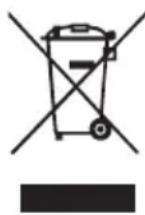
Do not dispose of electrical appliances as unsorted municipal waste, use separate collection facilities.
Contact your local government for information regarding the collection systems available.
If electrical appliances are disposed of in landfills or dumps, hazardous substances can leak into the groundwater and get into the food chain, damaging your health and well-being.
TROUBLESHOOTING
EN
| PROBLEM CAUSE SOLUTION | ||
| Line trimmer fails to start | ■ The battery pack is not attached to the line trimmer.■ No electrical contact between the trimmer and battery.■ The battery pack is depleted.■ The lock-off button and trigger are not depressed simultaneously. | ■ Attach the battery pack to the line trimmer.■ Remove battery, check contacts and reinstall the battery pack.■ Charge the battery pack.■ Press down the lock-off button and hold it, then depress the trigger to turn on the line trimmer. |
| Line trimmer stops while cutting | ■ The guard is not mounted on the trimmer, resulting in an overly long cutting line and motor overload.■ Heavy cutting line is used.■ The motor shaft or trimmer head is bound with grass.■ The motor is overloaded.■ The battery pack or line trimmer is too hot.■ The battery pack is disconnected from the tool.■ The battery pack is depleted. | ■ Remove the battery pack and mount the guard on the trimmer.■ Use recommended nylon cutting line with diameter no greater than 2.4mm.■ Stop the trimmer, remove the battery, and remove the grass from the motor shaft and trimmer head.■ Remove the trimmer head from the grass. The motor will recover to work as soon as the load is removed. When cutting, move the trimmer head in and out of the grass to be cut and remove no more than 20cm of length in a single cut.■ Allow the battery pack or trimmer to cool until the temperature drops below 67°C.■ Re-install the battery pack.■ Charge the battery pack. |
EN
| PROBLEM CAUSE SOLUTION | ||
| Trimmer head will not advance line | ■ The motor shaft or trimmer head is bound with grass.■ There is not enough line in the spool retainer.■ The trimmer head is dirty.■ Line is tangled in the spool retainer.■ The line is too short. | ■ Stop the trimmer, remove the battery, and remove the grass from the motor shaft and trimmer head.■ Remove the battery and replace the cutting line; follow the section “LINE REPLACEMENT” in this manual.■ Remove the battery and clean the spool retainer and spool base.■ Remove the battery, remove the line from the spool retainer and rewind; follow the section “LINE REPLACEMENT” in this manual.■ Remove the battery and pull the lines while alternately pressing down on and releasing the trimmer head. |
| Grass wraps around trimmer head and motor housing | ■ Cutting tall grass at ground level. | ■ Cut tall grass from the top down, removing no more than 20cm in each pass to prevent wrapping. |
| The blade is not cutting the line. | ■ The line-cutting blade on the edge of the guard has become dull. | ■ Sharpen the line-cutting blade with a file or replace it with a new blade. |
| Cracks on the trimmer head or the spool retainer comes loose with spool base. | ■ The trimmer head is worn out. | ■ Replace the trimmer head Immediately performed by a qualified service technician. |
| During line replace-ment, the line can’t be loaded into the trimmer head properly. | ■ Spool retainer’s LOAD lines do not align with the eyelets in the spool base.■ The trimmer line is not correctly inserted into the mounting hole in the eyelet. | ■ Rotate the spool retainer in the arrow direction to align the LOAD lines on the spool retainer with the eyelets in the spool base.■ Align the LOAD lines with the eyelets first, the insert the line into the mounting hole inside the eyelet. |
WARRANTY
EN
EGO WARRANTY POLICY
5 year warranty on EGO outdoor power equipment and 3 year warranty on EGO Power+ System battery packs and chargers.
Please contact EGO Customer Service on Australia 1300 000 EGO(1300 000 346),
New Zealand 0508 000 EGO (0508 000 346) any time you have questions or warranty claims.
LIMITED SERVICE WARRANTY
FOR FIVE YEARS from the date of original retail purchase, this EGO product is warranted against defects in material or workmanship. Defective product will receive free repair.
FOR THREE YEARS from the date of original retail purchase, the EGO Power+ System battery pack and charger are warranted against defects in material or workmanship. Defective product will receive free repair.
This warranty does not cover routine maintenance parts and consumables that can wear out from normal use within the warranty period.
■ This warranty applies only to the original purchaser from an authorised EGO retailer and may not be transferred.
■ The warranty period for any EGO product or part used for industrial, professional or commercial purpose is one year.
■ This warranty is void if the product has been used for rental purpose.
■ This warranty does not cover the damage resulting from modification, alteration or unauthorised repair.
■ This warranty only covers defects arising under normal usage and does not cover any malfunction, failure or defect resulting from misuse, abuse (including overloading of the product beyond capacity and immersion in water or other liquid), accidents, neglect or lack of proper installation, and improper maintenance or storage.
- This warranty does not cover normal deterioration of the exterior finish, including but not limited to scratches, dents, paint chips, or to any corrosion or discoloring by heat, abrasive and chemical cleaners.
HOW TO OBTAIN SERVICE
For warranty service, please contact EGO customer service on Australia 1300 000 EGO(1300 000 346).
New Zealand 0508 000 EGO (0508 000 346). When requesting warranty service, you must present the original dated sales receipt. An authorised service center will be selected to repair the product according to the stated warranty terms.
ADDITIONAL LIMITATIONS
Chervon Australia Pty Ltd ABN 36 165 077 501("Chervon") warrants to the original domestic purchaser that this product will be free from defects in materials and workmanship for 5 years from date of purchase, and any battery or charger will be free from defects in materials and workmanship for 3 years from date of purchase. To make a claim, return the faulty item together with proof of purchase directly to your closest service agent or to the place of purchase. Any handling and transportation costs (and other expenses incurred in claiming this warranty) are not covered by this warranty and will not be borne by Chervon. The replacement product or part or repaired product will be made available for your collection at an address nominated by Chervon. Where a valid warranty claim is made, Chervon will replace the defective product or repair the fault. Where the product is repaired, Chervon may use refurbished parts. This warranty does not cover normal wear and tear, misuse or abuse. This warranty may also be further limited or voided as specifically detailed in the product Manual. Chervon has no other liability under this warranty. The benefits to you given by this warranty are in addition to other rights and remedies imposed by State and Federal legislation that cannot be excluded. Our goods come with guarantees that cannot be excluded under the Australian Consumer Law. You are entitled to a replacement or refund for a major failure and compensation for any other reasonably foreseeable loss or damage. You are also entitled to have the goods repaired or replaced if the goods fail to be of acceptable quality and the failure does not amount to a major failure. Chervon Australia Pty Ltd, Unit 13, 1488 Ferntree Gully Rd, Knoxfield, VIC. 3180.
Phone Number: Australia 1300 000 EGO(1300 000 346), New Zealand 0508 000 EGO (0508 000 346).
Email address: support@egopowerplus.com.au.