
SC5299DP - Uncategorized INTEL - Free user manual and instructions
Find the device manual for free SC5299DP INTEL in PDF.


| Product Type | Server Chassis (tower/rack) |
| Brand | Intel |
| Model | SC5299DP |
| Dimensions (W x D x H) | 430 x 540 x 220 mm |
| Weight | 15 kg |
| Power Supply | 600 W (typical) |
| Cooling | 2 x 120 mm fans |
| Storage Bays | 6 internal bays (3.5" / 2.5") |
| Motherboard Compatibility | Intel® server motherboards (extended ATX format) |
| Main Features | Rack or tower mounting, cable management, security lock |
| Safety | Grounding, ESD protection, front panel lock switch |
| Maintenance and Cleaning | Clean with a dry, lint-free cloth; avoid moisture |
| Spare Parts and Repairability | Hot-swappable power supply, replaceable CR2032 battery |
| Operating Temperature | 10°C to 35°C |
| Operating Humidity | 20% to 80% non-condensing |
| Certifications | Class A (radio interference), UL, CE |
| Package Contents | Chassis, mounting kit, safety documentation |
| Warranty | 1 year (depending on retailer) |
Frequently Asked Questions - SC5299DP INTEL
User questions about SC5299DP INTEL
0 question about this device. Answer the ones you know or ask your own.
Ask a new question about this device
Download the instructions for your Uncategorized in PDF format for free! Find your manual SC5299DP - INTEL and take your electronic device back in hand. On this page are published all the documents necessary for the use of your device. SC5299DP by INTEL.
USER MANUAL SC5299DP INTEL
Intel® Entry Server Chassis SC5299-E DP/WS/BRP User Guide
A Guide for Technically Qualified Assemblers of Intel ^® Identified Subassemblies/Products
Intel Order Number D37596-002
Disclaimer
Information in this document is provided in connection with Intel® products. No license, express or implied, by estoppel or otherwise, to any intellectual property rights is granted by this document. Except as provided in Intel's Terms and Conditions of Sale for such products, Intel assumes no liability whatsoever, and Intel disclaims any express or implied warranty, relating to sale and/or use of Intel® products including liability or warranties relating to fitness for a particular purpose, merchantability, or infringement of any patent, copyright or other intellectual property right. Intel products are not designed, intended or authorized for use in any medical, life saving, or life sustaining applications or for any other application in which the failure of the Intel product could create a situation where personal injury or death may occur. Intel may make changes to specifications and product descriptions at any time, without notice.
Intel® server boards contain a number of high-density VLSI and power delivery components that need adequate airflow for cooling. Intel's own chassis are designed and tested to meet the intended thermal requirements of these components when the fully integrated system is used together. It is the responsibility of the system integrator that chooses not to use Intel developed server building blocks to consult vendor datasheets and operating parameters to determine the amount of airflow required for their specific application and environmental conditions. Intel Corporation can not be held responsible if components fail or the server board does not operate correctly when used outside any of their published operating or non-operating limits.
Intel, Intel Pentium, and Intel Xeon are trademarks or registered trademarks of Intel Corporation or its subsidiaries in the United States and other countries.
* Other names and brands may be claimed as the property of others.
Copyright © 2006, Intel Corporation. All Rights Reserved
Important Safety Instructions
Read all caution and safety statements in this document before performing any of the instructions. See also Intel Server Boards and Server Chassis Safety Information on the Intel® Server Deployment Toolkit CD and/or at http://support.intel.com/support/motherboards/server/sb/cs-010770.htm.
Heed safety instructions: Before working with your server product, whether you are using this guide or any other resource as a reference, pay close attention to the safety instructions. You must adhere to the assembly instructions in this guide to ensure and maintain compliance with existing product certifications and approvals. Use only the described, regulated components specified in this guide. Use of other products / components will void the UL listing and other regulatory approvals of the product and will most likely result in noncompliance with product regulations in the region(s) in which the product is sold.
System power on/off: The power button DOES NOT turn off the system AC power. To remove power from system, you must unplug the AC power cord from the wall outlet. Make sure the AC power cord is unplugged before you open the chassis, add, or remove any components.
Hazardous conditions, devices and cables: Hazardous electrical conditions may be present on power, telephone, and communication cables. Turn off the server and disconnect the power cord, telecommunications systems, networks, and modems attached to the server before opening it. Otherwise, personal injury or equipment damage can result.
Electrostatic discharge (ESD) and ESD protection: ESD can damage disk drives, boards, and other parts. We recommend that you perform all procedures in this chapter only at an ESD workstation. If one is not available, provide some ESD protection by wearing an antistatic wrist strap attached to chassis ground any unpainted metal surface on your server when handling parts.
ESD and handling boards: Always handle boards carefully. They can be extremely sensitive to ESD. Hold boards only by their edges. After removing a board from its protective wrapper or from the server, place the board component side up on a grounded, static free surface. Use a conductive foam pad if available but not the board wrapper. Do not slide board over any surface.
Installing or removing jumpers: A jumper is a small plastic encased conductor that slips over two jumper pins. Some jumpers have a small tab on top that you can grip with your fingertips or with a pair of fine needle nosed pliers. If your jumpers do not have such a tab, take care when using needle nosed pliers to remove or install a jumper; grip the narrow sides of the jumper with the pliers, never the wide sides. Gripping the wide sides can damage the contacts inside the jumper, causing intermittent problems with the function controlled by that jumper. Take care to grip with, but not squeeze, the pliers or other tool you use to remove a jumper, or you may bend or break the pins on the board.
About this Manual
Thank you for purchasing and using the Intel ^® Entry Server Chassis SC5299-E.
This manual is written for system technicians who are responsible for troubleshooting, upgrading, and repairing this server chassis. This document provides a brief overview of the features of the chassis, a list of accessories or other components you may need, troubleshooting information, and instructions on how to add and replace components on the Intel ^® Entry Server Chassis SC5299-E. For the latest version of this manual, see http://support.intel.com/support/motherboards/server/chassis/sc5299-e/.
Manual Organization
Chapter 1 provides a brief overview of the Intel ^® Entry Server Chassis SC5299-E. In this chapter, you will find a list of the server chassis features, photos of the product, and product diagrams to help you identify components and their locations.
Chapter 2 provides instructions on adding and replacing components. Use this chapter for step-by-step instructions and diagrams for installing or replacing components such as the fans, power supply, drives, and other components.
At the back of this book, you will find technical specifications, regulatory information, "getting help" information, and the warranty.
Product Contents, Order Options, and Accessories
This server chassis is compatible with the following Intel ^® Server Boards:
- Intel ^ Server Board S5000XVN
- Intel ^ Server Board S5000VSA
- Intel ^ Server Board S5000PSL
- Intel® Server Board S5000XSL
Your Intel ^® Entry Server Chassis SC5299-E ships with the following items:
- A power factor correction (PFC) power supply, installed in the chassis. Wattage of power supply will depend on the model of server chassis you purchased. Three power supply configurations are available.
- A box of hardware components, referred to below as the "hardware kit"
-
Fan cable, installed in the chassis
-
Chassis intrusion switch, installed in the chassis
- Front panel, installed in the chassis
- Attention document, in the chassis product box
- Intel® Entry Server Chassis SC5299-E Quick Start User's Guide, in the chassis product box
- Four M3 screws for installing 5.25-in drive component, in the hardware kit
- Fifteen 6-32 screws for mounting the server board to the chassis, in the hardware kit
- USB cable
In addition, you may need or want to purchase one or more of the following accessory items for your server:
Processor, memory FBDIMMs, hard drive, CD-ROM or DVD-ROM drive, RAID controller, operating system.
For information about which accessories, memory, processors, and third-party hardware have been tested and can be used with your server board, and for ordering information for Intel ^® products, see http://support.intel.com/support/motherboards/server/chassis/sc5299-e/compat.htm.
Additional Information and Software
If you need more information about this product or information about the accessories that can be used with this server chassis, use the following resources. These files are available at http://support.intel.com/support/motherboards/server/chassis/sc5299-e/
Unless otherwise indicated in the following table, once on this Web page, type the document or software name in the search field at the left side of the screen and select the option to search "This Product."
| For this information or software | Use this Document or Software |
| For in-depth technical information about this product, including dimensions and power characteristics | Intel®Entry Server Chassis SC5299-E Technical Product Specification |
| If you just received this product and need to install it | Intel®Entry Server Chassis SC5299-E Quick Start User's Guide in the product box |
| For virtual system tours and interactive repair information | A link to the SMaRT Tool is available under "Other Resources" at the right side of the screen athttp://support.intel.com/support/motherboards/server/chassis/sc5299-e |
| Accessories or other Intel server products | Spares and Configuration Guide |
| Hardware (peripheral boards, adapter cards) and operating systems that have been tested with this product | Tested Hardware/Operating Systems List |
| To make sure your system falls within the allowed power budget | Power Budget Tool athttp://support.intel.com/support/motherboards/server/chassis/sc5299-e |
| For software to manage your Intel® server | Intel® System Management Software |
Preface
Contents
Safety Information ....iii
Important Safety Instructions ....iii
Product Contents, Order Options, and Accessories ...... v
Additional Information and Software ...... vi
Server Chassis Features .... 1
Component Identification ....3
Front View Components ....3
Internal Components 5
Back Panel Components ....6
Front Panel 7
Peripheral Devices 8
Hard Disk Drives 8
Front Bezel Assembly 9
Rack-Mounted Systems 9
Mechanical Locks 10
Accessories and Order Codes ....10
Hardware Installations and Upgrades 11
Before You Begin 11
Tools and Supplies Needed 11
System References 11
Removing and Installing the Left Side Cover 11
Removing the Left Side Cover ....11
Installing the Left Side Cover 12
Removing and Installing the Front Bezel Assembly 13
Removing the Front Bezel Assembly 13
Installing the Front Bezel Assembly 14
Removing and Installing the Processor Air Duct 15
Removing the Processor Air Duct 15
Installing the Processor Air Duct 15
Installing or Removing a Server Board ....16
Installing and Removing a Fixed Hard Drive 22
Installing a Fixed Hard Drive 22
Removing a Fixed Hard Drive 28
Installing or Removing a DVD-ROM or CD-ROM Drive ....31
Installing a DVD-ROM or CD-ROM Drive ....31
Removing a CD-ROM or DVD-ROM Drive 33
Installing the Removing PCI Add-in Boards 34
Installing PCI Add-in Boards 34
Removing PCI Add-in Boards 36
Replacing the Front Panel Board 38
Replacing a System Fan 42
Replacing a Fixed Power Supply 44
Installing an Additional Hot Swap Power Supply Module (BRP configuration only) 47
Replacing a Hot Swap Power Supply (BRP configuration only) 48
Replacing a Hot Swap Power Supply Cage (BRP configuration only) 49
Installing Feet for a Pedestal-configured Chassis 54
Hot Swap Drive Cage Upgrade Install Instructions (optional) 55
Before You Begin 55
Kits Required 55
Tools and Supplies Needed 55
System References 55
Installing a Hot Swap Hard Drive Cage with a SAS/SATA or SCSI Backplane 56
Installing a Hot Swap Hard Drive 67
Rack Mount Kit Install Instructions (optional) 75
Before You Begin 75
Tools and Supplies Needed 75
System References 75
Setting up a Rack-configured Chassis 75
Technical Reference 87
Cable Routing 87
Power Supply Specifications 87
550-W Single Power Supply Input Voltages 87
550-W Single Power Supply Output Current 87
670-W Single Power Supply Input Voltages 88
670-W Single Power Supply Output Voltages 88
650-W Single Power Supply Input Voltages 88
650-W Single Power Supply Output Voltages 88
System Environmental Specifications 89
A. Safety Information 91
English 91
Server Safety Information 91
Safety Warnings and Cautions 91
Intended Application Uses 92
Site Selection 92
Equipment Handling Practices 92
Power and Electrical Warnings 92
System AccessWarnings 93
Rack Mount Warnings 94
Electrostatic Discharge (ESD) 94
Other Hazards 95
Deutsch 96
B. Installation/Assembly Safety Instructions 119
English 119
Deutsch 121
Français 124
Español 126
Italiano 128
C. Getting Help 131
World Wide Web 131
Telephone 131
U.S. and Canada 131
Europe 131
In Asia-Pacific region 132
Japan 132
Latin America 132
D. Intel ^® Server Issue Report Form 135
E. Warranty 139
Limited Warranty for Intel® Chassis Subassembly Products 139
Extent of Limited Warranty 139
Warranty Limitations and Exclusions 140
Limitations of Liability 140
How to Obtain Warranty Service 140
Telephone Support 141
Returning a Defective Product 141
F. Regulatory and Compliance Information ....143
Product Regulatory Compliance 143
Product Safety Compliance 143
Product EMC Compliance - Class A Compliance 144
Certifications / Registrations / Declarations 144
Product Regulatory Compliance Markings 145
Electromagnetic Compatibility Notices 146
FCC Verification Statement (USA) 146
Industry Canada (ICES-003) 147
Europe (CE Declaration of Conformity) 147
VCCI (Japan) 147
BSMI (Taiwan) 148
Korean Compliance (RRL) 148
Regulated Specified Components 148
Restriction of Hazardous Substances (RoHS) Compliance 149
End of Life / Product Recycling 149
List of Figures
Figure 1. Front View of Intel ^® Entry Server Chassis SC5299-E.... 1
Figure 2. Front View Components (with Front Bezel Assembly).... 3
Figure 3. Front View Components (without Front Bezel Assembly)....4
Figure 4. Internal Components....5
Figure 5. Back Panel Components....6
Figure 6. Front Panel Components ...... 7
Figure 7. Optional Peripheral Devices....8
Figure 8. Mechanical Locks....10
Figure 9. Removing Left Side Cover 12
Figure 10. Installing Left Side Cover .... 12
Figure 11. Removing Front Bezel Assembly.... 13
Figure 12. Installing the Front Bezel Assembly....14
Figure 13. Removing Processor Air Duct....15
Figure 14. Installing Processor Air Duct.... 16
Figure 15. Removing Drive Cage EMI Shield from Fixed Drive Cage.... 17
Figure 16. Removing Fixed Hard Drive Cage 18
Figure 17. Removing PCI Card Guide....18
Figure 18. Re-installing PCI Card Guide into Chassis 19
Figure 19. Inserting Fixed Hard Drive Cage into Chassis 20
Figure 20. Re-attaching Drive Cage EMI Shield 21
Figure 21. Drive Bay Slot Order 22
Figure 22. Removing Drive Cage EMI Shield from Chassis....23
Figure 23. Removing PCI Card Guide....24
Figure 24. Routing Hard Drive Power Cables 24
Figure 25. Unlatching Drive Latch....25
Figure 26. Inserting Hard Drive into Drive Cage 25
Figure 27. Latching Drive Latch 26
Figure 28. Drive Bay Slot Order 26
Figure 29. Cabling a Fixed Hard Drive....27
Figure 30. Re-installing Drive Cage EMI Shield.... 27
Figure 31. Re-installing PCI Card Guide....28
Figure 32. Preparing Fixed Hard Drive for Removal 29
Figure 33. Removing Fixed Hard Drive from Drive Bay 30
Figure 34. Re-installing Drive Cage EMI Shield.... 30
Figure 35. Removing 5.25-in Drive EMI Shield 31
Figure 36. Installing CD-ROM or DVD-ROM Drive 32
Figure 37. Removing CD-ROM or DVD-ROM Drive 33
Figure 38. Installing 5.25-in Drive EMI Shield 34
Figure 39. Opening PCI Add-in Card Retention Device....35
Figure 40. Removing PCI Slot Shield....35
Figure 41. Installing PCI Add-in Board....36
Figure 42. Opening PCI Add-in Card Retention Device....37
Figure 43. Removing PCI Add-in Board.... 37
Figure 44. Replacing PCI Slot Shield.... 38
Figure 45. Removing Right Side Cover from Chassis 39
Figure 46. Unattaching Front Panel Board from Chassis 39
Figure 47. Removing Front Panel Board from Chassis 40
Figure 48. Removing Standoffs from Front Panel.... 40
Figure 49. Installing Front Panel Board in Chassis.... 41
Figure 50. Positioning Front Panel Board in Chassis 41
Figure 51. Re-installing Right Side Cover on Chassis 42
Figure 52. Removing Fan Duct / System Fan Assembly 43
Figure 53. Re-installing Fan Duct / System Fan Assembly.... 43
Figure 54. Unlocking Fixed Power Supply from Chassis.... 44
Figure 55. Removing Fixed Power Supply from Chassis.... 45
Figure 56. Inserting Fixed Power Supply in Chassis 45
Figure 57. Locking Fixed Power Supply into Chassis.... 46
Figure 58. Removing Power Supply Filler Panel 47
Figure 59. Inserting Additional Hot Swap Power Supply Module.... 47
Figure 60. Removing Hot Swap Power Supply Module from Chassis 48
Figure 61. Inserting Hot Swap Power Supply Module in Chassis....48
Figure 62. Removing Hot Swap Power Supply Module.... 49
Figure 63. Detaching Hot Swap Power Supply Cage from Inside of Chassis.... 50
Figure 64. Detaching Hot Swap Power Supply Cage from Rear of Chassis 50
Figure 65. Removing Rear Support Bracket from Hot Swap Power Supply Cage .... 51
Figure 66. Attaching Rear Support Bracket to Power Supply Cage 51
Figure 67. Securing Hot Swap Power Supply Cage to Rear of Chassis.... 52
Figure 68. Securing Hot Swap Power Supply Cage to Inside of Chassis.... 52
Figure 69. Re-installing Hot Swap Power Supply Module(s) 53
Figure 70. Installing Feet on Chassis....54
Figure 71. Removing Fixed Drive Cage EMI Shield from Chassis 56
Figure 72. Removing Fixed Hard Drive Cage from Chassis....57
Figure 73. Removing Stud Screws from Hot Swap Drive Cage.... 58
Figure 74. Attaching Latch Plate to Hot Swap Drive Cage 58
Figure 75. Attaching Filler Panel to Hot Swap Drive Cage 59
Figure 76. Removing Thumb Screws from Backplane....59
Figure 77. Attaching Fan Bracket to Hot Swap Drive Cage (SAS/SATA drive cage illustrated).. 60
Figure 78. Attaching Fan to Fan Bracket 61
Figure 79. Inserting Hot Swap Drive Cage into Chassis....62
Figure 80. Cabling the SCSI Hot Swap Drive Cage....63
Figure 81. Layout of Cable Connectors on the SAS/SATA Backplane (Backplane without expander shown)....64
Figure 82. Making Six-drive SAS/SATA Hot-Swap Drive Cage Backplane without Expander Connections (fan bracket not shown in the illustration for clarity)....65
Figure 83. Making Six-drive Hot Swap Drive Cage Backplane with Expander Connections (fan bracket not shown in the illustration for clarity)....66
Figure 84. Opening Drive Bay Access Door 67
Figure 85. Releasing Drive Carrier from Hot Swap Drive Cage....68
Figure 86. Removing Retention Device from Drive Carrier.... 68
Figure 87. Installing Hard Drive into Drive Carrier....69
Figure 88. Re-installing Drive Carrier in Hot Swap Drive Cage....69
Figure 89. Closing Drive Bay Access Door 70
Figure 90. Opening Drive Bay Access Door....70
Figure 91. Removing Drive Carrier from Hot Swap Drive Cage....71
Figure 92. Removing Hard Drive from Drive Carrier ....71
Figure 93. Installing Hard Drive in Drive Carrier....72
Figure 94. Installing Plastic Retention Device in Drive Carrier....72
Figure 95. Re-installing Drive Carrier in Hot Swap Drive Cage....73
Figure 96. Closing Drive Bay Access Door 73
Figure 97. Removing Chassis Feet....76
Figure 98. Removing Top Side Cover from Chassis.... 76
Figure 99. Removing PCI Card Guide....77
Figure 100. Removing Plastic Filler Panel from Chassis 78
Figure 101. Removing Plastic Plugs 79
Figure 102. Removing Rear Screws 79
Figure 103. Removing Plastic Plugs from Top Side Cover 80
Figure 104. Installing Rack Handle on Left Side Cover....80
Figure 105. Affixing Label to Front Panel....81
Figure 106. Installing Top Side Cover on Chassis 81
Figure 107. Detaching Inner Rack Rail from Rack Rail Assembly ....82
Figure 108. Attaching Inner Rack Rails to Chassis.... 83
Figure 109. Attaching Outer Rack Rails to Rack Uprights 84
Figure 110. Installing Chassis into Rack....85
List of Tables
Table 1. Breakdown of Intel® Entry Server Chassis SC5299-E Configurations ..... 1
Table 2. Server Chassis Features....2
Table 3. Accessories and Order Codes ...... 10
Table 4. 550-W Power Supply Output Capability.... 87
Table 5. 670-W Power Supply Output Capability.... 88
Table 6. 650-W Power Supply Output Capability.... 88
Table 7. System Environmental Specifications 89
Table 8. Product Regulatory Compliance Markings....145
1 Server Chassis Features
This chapter describes the main features of the Intel ^® Entry Server Chassis SC5299-E. The location of important chassis components and connections, as well as a description of LED identification, are also presented.
natural_image
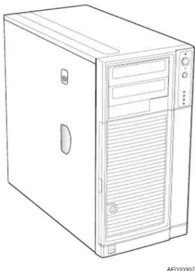
Line drawing of a desktop computer tower case with ventilation slots and drive bays (no text or symbols)Figure 1. Front View of Intel® Entry Server Chassis SC5299-E
The Intel ^® Entry Server Chassis SC5299-E is a 5.2U pedestal ^1 server chassis and is available in three configurations: DP (dual-processor), WS (workstation), and BRP (base redundant power). The chassis is designed to support the Intel ^® Server Boards S5000XVN, S5000PSL, S5000XSL and S5000VSA. The type of server board supported is dependent upon the configuration purchased. See Table 1 for a list of the Intel ^® server boards that are supported by each server chassis configuration.
Table 1. Breakdown of Intel® Entry Server Chassis SC5299-E Configurations
| Intel®Entry Server Chassis SC5299-E Configuration | Intel®Server Boards Supported1 |
| DP (Dual-processor) Intel | ®Server Boards S5000VSA, S5000XSL and S5000PSL |
| WS (Workstation) Intel | ®Server Board S5000XVN |
| BRP (Base Redundant Power) Intel | ®Server Boards S5000VSA, S5000XSL and S5000PSL |
NOTES: 1. For updated server board support, go to http://support.intel.com/support/motherboards/server/chassis/sc5299-e/.
Table 2 summarizes the features of the Intel ^ Entry Server Chassis SC5299-E.
Table 2. Server Chassis Features
| Feature Description | |
| Dimensions (pedestal) | 17.8 in (45.2 cm) high with feet; 17.6 in (44.7 cm) without feet9.256 in (23.5 cm) wide19.2 in (48.7 cm) deep |
| Dimensions (rack) | 9.256 in (23.5 cm) high without rack bezel; 10.3 in (26.2 cm) high with rack bezel17.6 in (44.7 cm) wide19.2 in (48.7 cm) deep |
| Hard drive cage | One removable fixed hard drive cage that can accept up to 6 tool-less cabled 3.5-in x 1-in hard drives.NOTE: An optional SCSI or SAS/SATA hot swap backplane hard drive cage (capable of handling up to 6 SCSI, SATA or SAS hot-swappable hard drives) can be purchased to replace the fixed hard drive cage. |
| Peripherals | Two tool-less 5.25-in device drive bays for CD-ROM, DVD-ROM drive, or tape drive |
| Front panel | One for the DP/WS/BRP chassis configurations. |
| Front Panel LEDs and displays | NIC1 ActivityNIC2 ActivityPower / SleepHard Drive ActivitySystem StatusNMINOTE: |
| Power Supply Wattage of | power supply is dependent on configuration of server chassis purchased:DP - ships with a 550-W PFC tool-less fixed power supplyWS - ships with a 670-W PFC tool-less fixed power supplyBRP - ships with a 650-W PFC redundant power supply module in a 1+0 configuration. An additional module can be purchased as an accessory to create a 1+1 configuration. |
| Fans | One 120-mm system fanOne power supply fan^1 Processor fans for active thermal solutionFan with optional hot swap drive kit upgradeFixed hard drive fan with WS chassis configuration |
| USB | Two front panel USB ports |
NOTES:
1. Power supply fan integrated into power supply module.
Component Identification
Front View Components
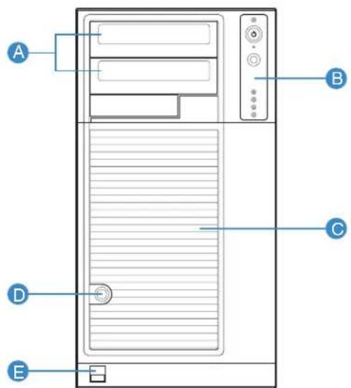
TP02345
| A. 5.25-in Device Drive Bays |
| B. Front Panel |
| C. Drive Bay Access Door |
| D. Door Lock |
| E. Front Panel USB Ports |
Figure 2. Front View Components (with Front Bezel Assembly)
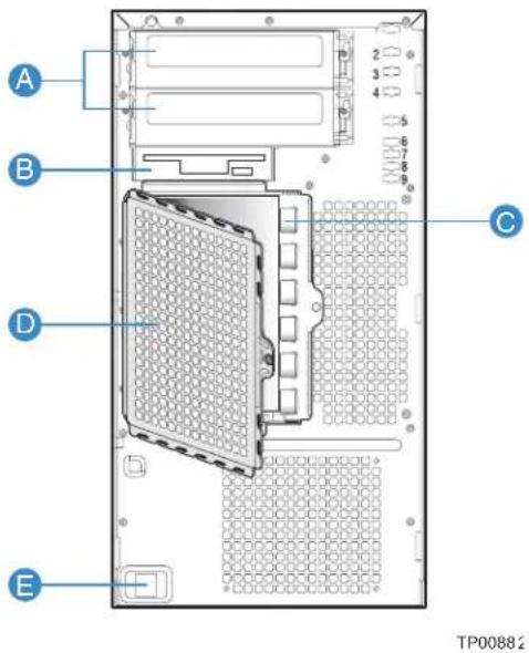
A. 5.25-in Device Drive Bays
B. 3.5-in Device Drive Bay
C. Hard Drive Cage
D. Drive Bay EMI Shield (shown open)
E. Front Panel USB Ports
Figure 3. Front View Components (without Front Bezel Assembly)
Internal Components
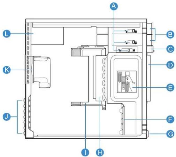
TP02033
A. Tool-less Device Bay Locks
B. 5.25-in Device Bays
C. 3.5-in Device Bay
D. Drive Bay EMI Shield
E. Drive Cage Retention Mechanism
F. PCI Add-in Card Guide
G. Front Panel USB Ports
H. Fixed Hard Drive Cage
I. Large Processor Air Duct
J. Rear Tool-less PCI Retention Mechanisms
K. Fan Duct / System Fan Assembly
L. Power Supply
Figure 4. Internal Components
Back Panel Components
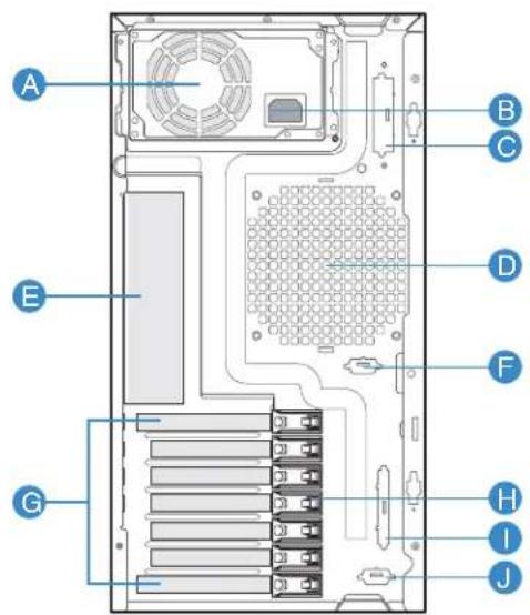
TP00880
A. Power Supply
NOTE: Fixed Power Supply shown. Your Power Supply may vary depending on chassis configuration purchased
B. A/C Power In
NOTE: Fixed Power Supply shown. Your Power Supply may vary depending on chassis configuration purchased.
C. Alternate external SCSI knockout
D. System Fan
E. I/O Shield
NOTE: I/O connectors vary, depending on the server board installed. See your server board documentation for port identification
F. Alternate Serial B port knockout
G. PCI Add-in Card slots
H. PCI Tool-less Card Retention Mechanisms
I. External SCSI knockout
J. Serial B port knockout
Figure 5. Back Panel Components
Front Panel
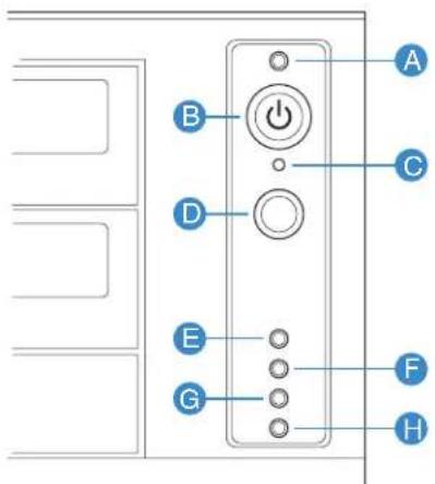
TP02346
| Callout Feature | 1,2 | Function |
| A. Power/Sleep LED Continuous green light indicates the system has power applied to it.Continuous amber light indicates the system is in S1 Sleep state.No light indicates the power is off / or the system is in S4 Sleep state. | ||
| B. Power/Sleep LED Powers the system off or on. | ||
| C. | NMI Button | Used to force system halt and dump memory contents to screen or file. |
| D. Reset Button Reboots and initializes the system. | ||
| E.F. | NIC 1 Activity LEDNIC 2 Activity LED | Continuous green light indicates a link between system and network.Blinking green light indicates network activity.No light indicates the NIC is disconnected. |
| G. Hard Drive ActivityLED | Random blinking green light indicates hard drive activity (SCSI or SAS/SATA).Continuous amber light indicates a hard drive fault.No light indicates no hard disk drive activity. | |
| H. Status LED Solid green indicates system ready (not supported by all server boards).Blinking green indicates processor or memory disabled.Solid amber indicates a critical temperature or voltage fault, or a missing CPU/terminator.Blinking amber indicates a power fault, fan fault, or a non-critical temperature or voltage fault.No light indicates a fatal error during POST. | ||
NOTES:
1. LED status may vary depending on server board integrated.
Figure 6. Front Panel Components
Peripheral Devices
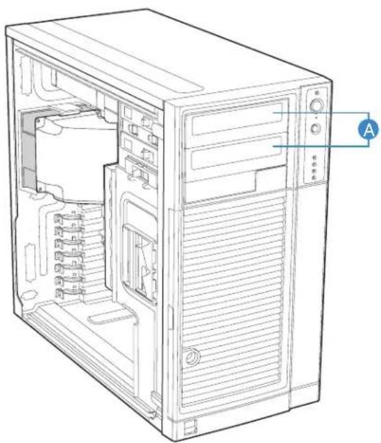
The server chassis provides locations and hardware for installing hard drives, a floppy drive, a CD-ROM drive, a DVD-ROM drive or a tape drive. The drives must be purchased separately. The following figure shows the available options.
natural_image
Line drawing of a desktop computer tower showing internal components and ventilation slots (no text or labels)TP02032
NOTE: It is recommended that screws be used to secure large devices if shipping chassis integrated.
Figure 7. Optional Peripheral Devices
Hard Disk Drives
The server chassis ships with one fixed hard drive cage capable of supporting up to six cabled 3.5-in x 1-in hard drives. Power requirements for each individual hard drive may limit the maximum number of drives that can be integrated into the server chassis.
An optional hot-swap SCSI or SAS/SATA backplane hard drive cage (capable of handling up to six hot-swappable SCSI, SATA or SAS hard drives) may be purchased to replace the fixed hard drive cage. See Table 3 for order code information.
For instructions on installing hard drives, see “Installing and Removing a Fixed Hard Drive”.
Note: Drives can consume up to 18.4 watts of power each. Drives must be specified to run at a maximum ambient temperature of 45C.
Note: The Intel ^® Entry Server Chassis SC5299-E does not support all SCSI or Serial ATA hard drives. See “Additional Information and Software” for an web link to a list of supported hardware.
Front Bezel Assembly
The front bezel assembly provides a snap-on design that allows for maximum airflow through the server chassis.
All configurations of the server chassis ship with a two-piece front bezel assembly.
Rack-Mounted Systems
Your Intel ^® Entry Server Chassis SC5299-E can be optionally mounted into a rack. Instructions for installing your chassis into a rack are included with the rail kit.
The order number for the rack mounting kit is APP3RACKIT.
Mechanical Locks
All configurations of the server chassis can support the installation of a padlock loop (see letter “A” in the following figure) at the rear of the chassis. Additionally, the server chassis ships with a two-position mechanical lock (see letter “B”) on the front bezel assembly to prevent access to the hard drives and the interior of the chassis.
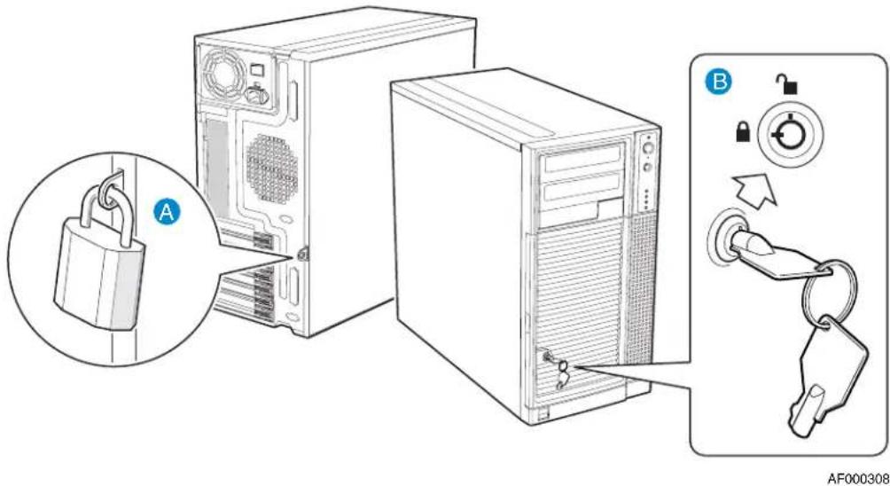
Figure 8. Mechanical Locks
Accessories and Order Codes
For a complete list of spares and accessories available for your chassis, see:
http://support.intel.com/go/serverbuilder
Table 3. Accessories and Order Codes
| Accessory Order Code | |
| SAS/SATA Hot Swap Drive Bay Upgrade Kit AXX6SASDB | |
| SCSI Hot Swap Drive Bay Upgrade Kit AXX6SCSIDB | |
| Hot Swap Conversion Kit APP3HSDBKIT | |
| Rack Mount Kit APP3RACKIT |
2 Hardware Installations and Upgrades
This document provides instructions for adding and replacing chassis components. For instructions on replacing components on the server board, such as the processor and memory FBDIMMs, see the instructions provided with the server board.
Before You Begin
Before working with your server product, review the important safety information listed in Appendix A, “Safety Information”.
Tools and Supplies Needed
- Phillips* (cross head) screwdriver (#1 bit and #2 bit)
- Needle-nosed pliers
- Anti-static wrist strap and conductive foam pad (recommended)
• Hex nut driver (6 mm)
System References
All references to left, right, front, top, and bottom assume the reader is facing the front of the chassis as it would be positioned for pedestal operation.
Removing and Installing the Left Side Cover
Warning: This chassis must be operated with the left side cover installed to ensure proper cooling.
Removing the Left Side Cover
The Intel ^® Entry Server Chassis SC5299-E must be operated with the left side cover in place to ensure proper cooling. You will need to remove the left side cover to add or replace components inside of the platform. Before removing the left side cover, power down the server and unplug all peripheral devices and the AC power cable.
Note: A nonskid surface or a stop behind the chassis may be needed to prevent the chassis from sliding on your work surface.
- Observe the safety and ESD precautions listed in Appendix A, "Safety Information".
-
Turn off all peripheral devices connected to the server. Turn off the server.
-
Disconnect the AC power cord(s).
-
If present, remove the two screws (see letter "A" in the following figure). Push in on latch with your right hand (see letter "B"), and with your left hand, grasp the rear cover clasp and slide the left side cover rearward to remove from chassis (see letter "C").
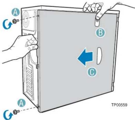
Figure 9. Removing Left Side Cover
Installing the Left Side Cover
Warning: This chassis must be operated with the left side cover installed to ensure proper cooling.
-
Slide the left side cover on the chassis and latch securely (see letter "A" in the following figure).
-
(Optional) Replace screws (see letter "B").
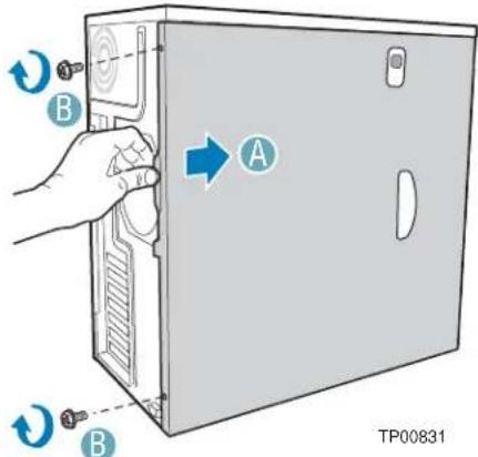
Figure 10. Installing Left Side Cover
- Reconnect all peripheral devices and the AC power cord. Power up the server.
Removing and Installing the Front Bezel Assembly
All configurations of the Intel ^® Entry Server Chassis SC5299-E ship with a two-piece front bezel assembly.
Removing the Front Bezel Assembly
- Observe the safety and ESD precautions listed in Appendix A, "Safety Information".
- Turn off all peripheral devices connected to the server. Turn off the server.
- Disconnect the AC power cord.
- Remove the left side cover. For instructions, see "Removing the Left Side Cover".
- Disengage the two bezel tabs from the left side of the chassis (see letter "A" in the following figure). Rotate the left side of the front bezel assembly outward slightly (see letter "B"). Disengage the three clips that attach the right side of the front bezel assembly to the chassis and remove (see letter "C").
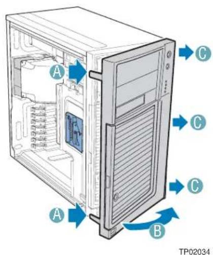
Figure 11. Removing Front Bezel Assembly
Installing the Front Bezel Assembly
- Line up the three clips on the right-side of the front bezel assembly with the corresponding slots on the right-side of the chassis (see letter "A" in the following figure). Engage the clips with the slots (see letter "B"). Rotate the left side of the front bezel assembly towards the chassis (see letter "C"). Snap the two bezel tabs into the corresponding recesses at the left edge of the chassis front panel (see letter "D").
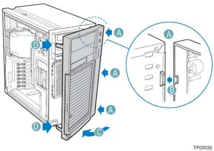
Figure 12. Installing the Front Bezel Assembly
- Reinstall the left side cover. For instructions, see "Installing the Left Side Cover".
- Reconnect all peripheral devices and the AC power cable. Power up the server.
Removing and Installing the Processor Air Duct
Warning: Always operate your server chassis with the processor air duct in place. This air duct is required for proper airflow within the chassis.
Warning: The processor air duct must only be used with active thermal solutions.
When adding or replacing a processor, first remove the processor air duct, and then refer to your server board User Guide for instructions on processor installation and removal. Return to these instructions to reinstall the processor air duct after you have installed your processor and heat sink.
Removing the Processor Air Duct
- Observe the safety and ESD precautions listed in Appendix A, "Safety Information".
- Power down the server and unplug all peripheral devices and the AC power cable.
- Remove the left side cover. For instructions, see "Removing the Left Side Cover".
- Loosen the two mounting screws and remove the processor air duct.
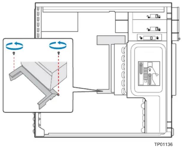
Figure 13. Removing Processor Air Duct
- Save the screws. You will need them to re-install the processor air duct.
Installing the Processor Air Duct
Warning: DO NOT operate the server chassis without the processor air duct in place. The processor air duct is required for proper airflow within the chassis.
- Lower the processor air duct into the chassis and line it up with the two mounting holes in chassis. Secure the processor air duct to the chassis with two mounting screws.
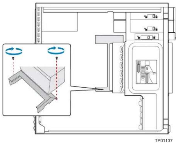
Figure 14. Installing Processor Air Duct
-
Install the left side cover. For instructions, see "Installing the Left Side Cover".
-
Plug all peripheral devices and the AC power cable into the server. Power up the server.
Installing or Removing a Server Board
Note: The type of Intel ^ Server Board you can install in your chassis will depend upon the model of chassis you purchased. For a breakout of server board/chassis model compatibility, see Table 1, “Breakdown of Intel ^ Entry Server Chassis SC5299-E Configurations”.
To install or remove a server board, do the following:
-
Observe the safety and ESD precautions listed in Appendix A, "Safety Information".
-
Power down the server and unplug all peripheral devices and the AC power cable.
-
Remove the left side cover. For instructions, see "Removing the Left Side Cover".
-
Remove the front bezel assembly. For instructions, see "Removing the Front Bezel Assembly".
-
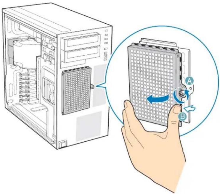
Loosen thumb screw and remove the drive cage EMI shield (see letter "A" in the following figure).
natural_image
Illustration of a computer tower with an open case and a hand holding a grid device labeled A and B, showing internal components and a blue circular arrow indicating rotation (no text or symbols beyond labels)TP01869
Figure 15. Removing Drive Cage EMI Shield from Fixed Drive Cage
-
Disconnect cables from any installed fixed hard drives. If necessary, remove hard drives from fixed hard drive cage. For instructions on removing fixed hard drives, see "Removing a Fixed Hard Drive".
-
Push the blue plastic release mechanism upward to release the fixed hard drive cage (see letter "A" in the following figure). Once released, pull the fixed hard drive cage from the chassis (see letter "B").
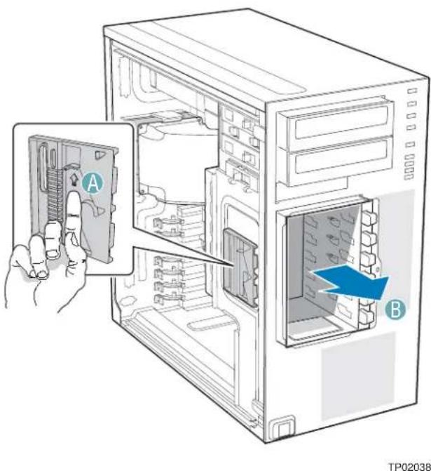
Figure 16. Removing Fixed Hard Drive Cage
- Remove any PCI add-in boards that are present.
- Remove the PCI card guide by pressing in on the blue tabs (see letter "A" in the following figure) and pulling the PCI card guide outward (see letter "B").
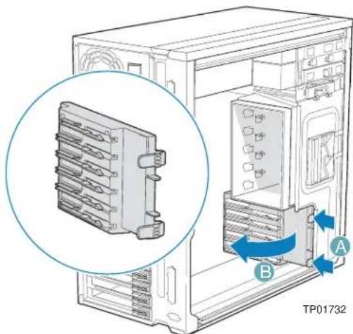
Figure 17. Removing PCI Card Guide
-
Remove the processor air duct. For instructions, see "Removing the Processor Air Duct".
-
If installing a server board, refer to your Intel ^® Server Board User's Guide and/or Quick Start User's Guide for installation instructions. Use the mounting screws, bumpers and standoffs (if necessary) that came with your chassis to secure the server board to the chassis. Make sure the server board is properly seated and then tighten the screws firmly, starting with the screws at the center of the server board.
If removing a server board, disconnect all cables connected to the server board. Refer to your Intel ^® Server Board User's Guide and/or Quick Start User's Guide for additional removal instructions.
-
Reinstall the processor air duct. For instructions, see "Installing the Processor Air Duct".
-
Re-install the PCI card guide. Insert tabs on left side of PCI card guide into slots in chassis (see letter "A" in the following figure). Swing PCI card guide into chassis until right-side blue tabs snap into place (see letter "B").
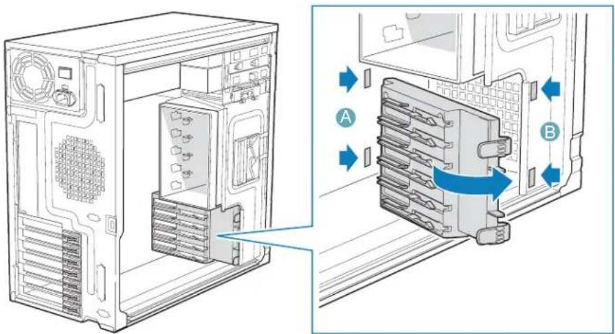
TP01735
Figure 18. Re-installing PCI Card Guide into Chassis
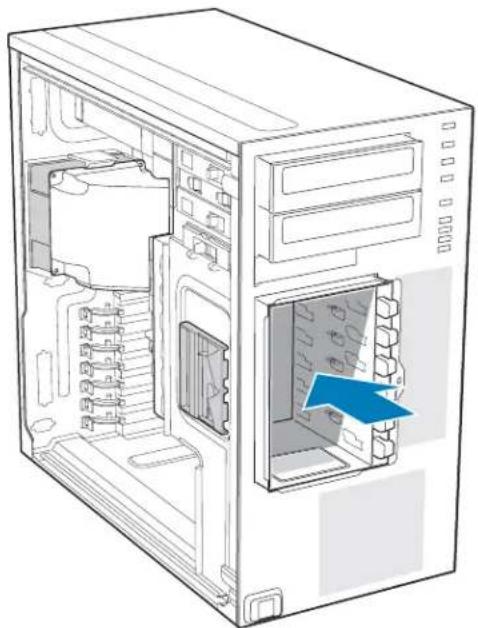
- Slide the fixed hard drive cage into the drive bay slot of the chassis. You should hear a click when the blue plastic retention mechanism locks into place.
natural_image
Diagram of a desktop computer tower showing internal components and a blue arrow pointing to a specific interior space (no text or symbols present)TP02039
Figure 19. Inserting Fixed Hard Drive Cage into Chassis
-
If previously removed, install fixed hard drives and connect power and data cables. For instructions, see "Installing a Fixed Hard Drive".
-
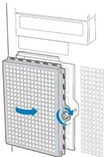
Re-attach the drive cage EMI shield to the fixed hard drive cage and tighten the thumb screw.
natural_image
Diagram of a grid-based device with directional arrows indicating rotation or movement (no text or symbols)AF000315
Figure 20. Re-attaching Drive Cage EMI Shield
- Re-install the front bezel assembly. For instructions, see "Removing and Installing the Front Bezel Assembly"
- Re-install the left side cover. For instructions, see "Installing the Left Side Cover"
- Plug all peripheral devices and the AC power cable(s) back into the server. Power up the server.
Installing and Removing a Fixed Hard Drive
Up to six fixed hard drives can be installed in the fixed hard drive cage that ships with the Intel ^® Entry Server Chassis SC5299-E. Power requirements for each individual hard drive may limit the maximum number of drives that can be integrated into the server chassis.
Note: The Intel ^ Entry Server Chassis SC5299-E does not support all hard drives. See "Additional Information and Software" for a web link to a list of supported hard drives.
Installing a Fixed Hard Drive
Caution: Fixed drives are NOT hot swappable. Before removing or replacing the drive, you must first take the server out of service, turn off all peripheral devices connected to the system, turn off the system by pressing the power button, and unplug the AC power cord from the system or wall outlet.
Warning: Drive bay slots 1, 3, and 5 MUST be populated first. Failure to do so could result in thermal issues within the chassis.
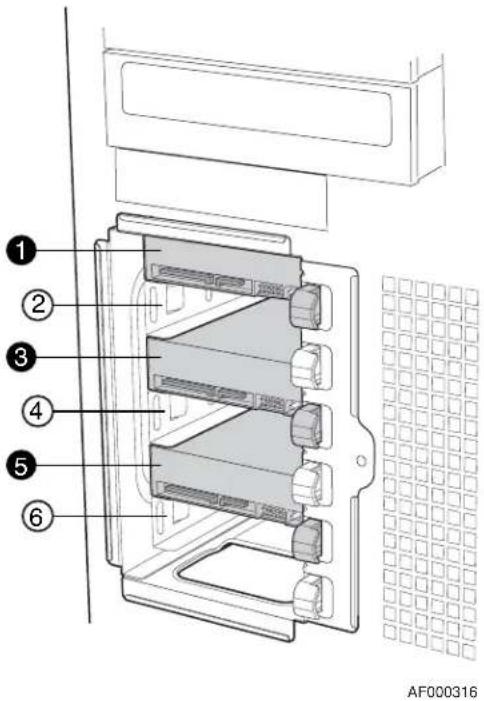
Note: SAS/SATA drives illustrated.
Figure 21. Drive Bay Slot Order
- Observe the safety and ESD precautions listed in Appendix A, "Safety Information".
-
Power down the server and unplug all peripheral devices and the AC power cable.
-
Remove the left side cover. For instructions, see "Removing the Left Side Cover".
-
Remove the front bezel assembly. For instructions, see "Removing the Front Bezel Assembly".
-
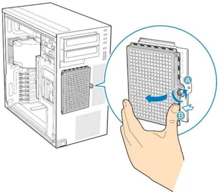
Loosen thumb screw and remove the drive cage EMI shield (see letter "A" in the following figure).
natural_image
Illustration of a computer tower with an open case and a hand holding a grid device labeled A and B, showing internal components and a blue circular arrow indicating rotation (no text or symbols beyond labels)TP01869
Figure 22. Removing Drive Cage EMI Shield from Chassis
-
Remove any PCI add-in boards that use the PCI card guide. For instructions, see "Removing PCI Add-in Boards".
-
Remove the PCI card guide by pressing in on the blue tabs (see letter "A" in the following figure) and pulling the PCI card guide outward (see letter "B").
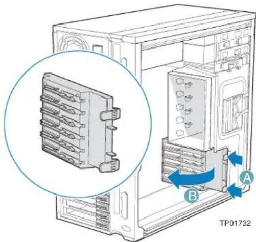
Figure 23. Removing PCI Card Guide
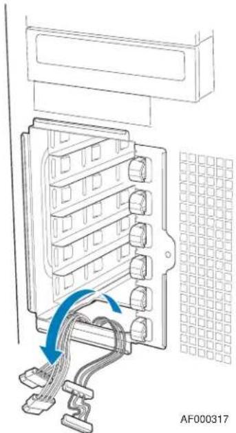
- Route the required power cables (connectors P8-P13) from behind the PCI card guide through the cable routing area at the bottom of the fixed drive cage.
natural_image
Diagram of an electrical enclosure with cable routing and grid pattern (no text or symbols)Figure 24. Routing Hard Drive Power Cables
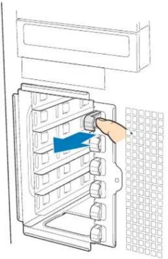
- Pull the drive latch forward to unlatch the drive locking assembly for the drive bay you want to install a hard drive in.
natural_image
Diagram of a hand inserting a component into an appliance panel with a blue arrow indicating direction (no text or symbols present)AF000318
Figure 25. Unlatching Drive Latch
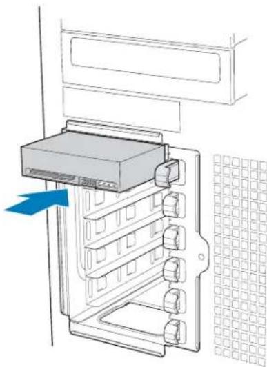
- Insert fixed hard drive into drive bay and push until it stops. Ensure that the power and data connector end of the hard drive is facing forward
natural_image
Diagram of an electronic device with a rack-mounted unit and a grid-patterned panel (no text or symbols)AF000319
Figure 26. Inserting Hard Drive into Drive Cage
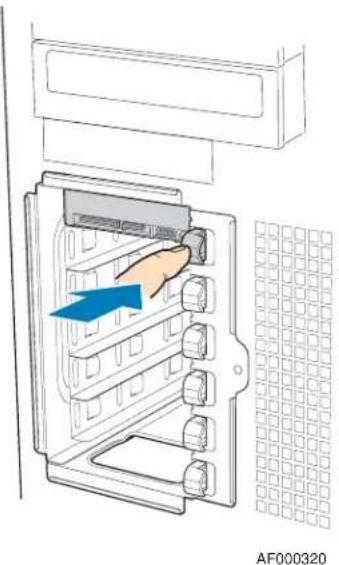
- Push drive latch in to lock hard drive into drive bay
natural_image
Diagram of a refrigerator interior with a hand inserting a component, showing no text or symbols on the main structure.Figure 27. Latching Drive Latch
- Install additional drives as necessary.
Warning: Drive bay slots 1, 3, and 5 MUST be populated first. Failure to do so could result in thermal issues within the chassis.
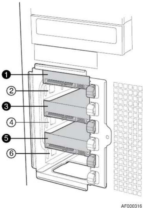
Figure 28. Drive Bay Slot Order
- Install power (see letter "A" in the following figure) and data (see letter "B") cables to each of the installed drives. The cables route through the oval opening at the bottom of the fixed drive cage.
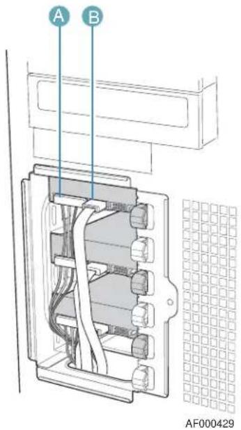
Figure 29. Cabling a Fixed Hard Drive
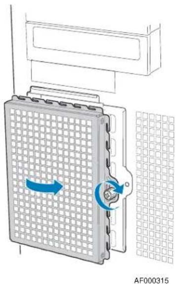
- Re-attach the drive cage EMI shield to the chassis and tighten the thumb screw.
natural_image
Diagram of a grid-based device with directional arrows indicating rotation, mounted on a panel (no text or symbols)Figure 30. Re-installing Drive Cage EMI Shield
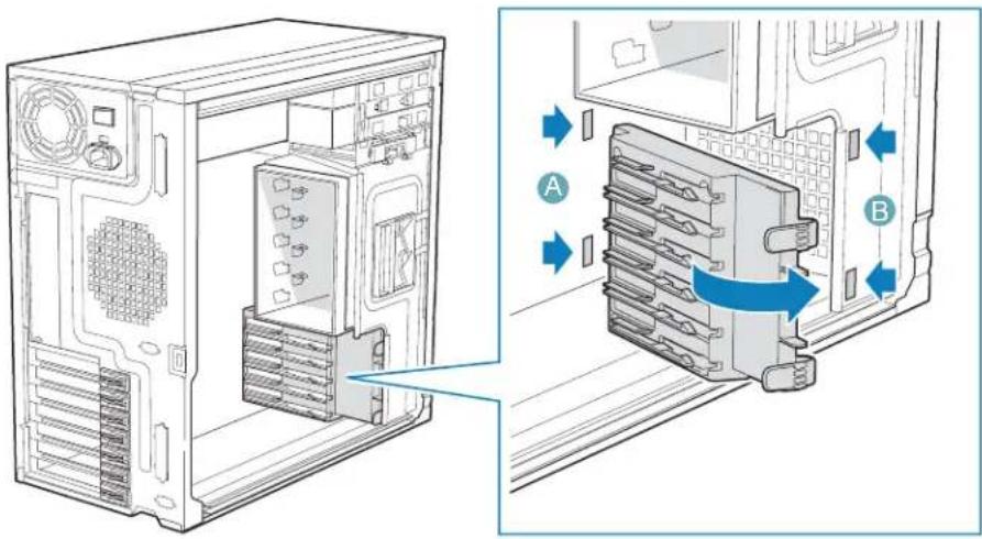
- Re-install the PCI card guide. Insert tabs on left side of PCI card guide into slots in chassis (see letter "A" in the following figure). Swing PCI card guide into chassis until right-side blue tabs snap into place (see letter "B").
TP01735
Figure 31. Re-installing PCI Card Guide
- Re-install any PCI add-in cards that were removed. For instructions, see "Installing PCI Add-in Boards".
- Re-install the front bezel assembly. For instructions, see "Installing the Front Bezel Assembly"
- Re-install the left side cover. For instructions, see "Installing the Left Side Cover"
- Plug all peripheral devices and the AC power cable back into the server. Power up the server.
Removing a Fixed Hard Drive
Caution: Fixed drives are NOT hot swappable. Before removing or replacing the drive, you must first take the server out of service, turn off all peripheral devices connected to the system, turn off the system by pressing the power button, and unplug the AC power cord from the system or wall outlet.
- Observe the safety and ESD precautions listed in Appendix A, "Safety Information".
- Power down the server and unplug all peripheral devices and the AC power cable.
- Remove the left side cover. For instructions, see "Removing the Left Side Cover".
-
Remove the front bezel assembly. For instructions, see "Removing and Installing the Front Bezel Assembly".
-
Loosen thumb screw (see letter "A" in the following figure). Apply slight pressure to right side of drive bay access door and swing door outward (see letter "B").
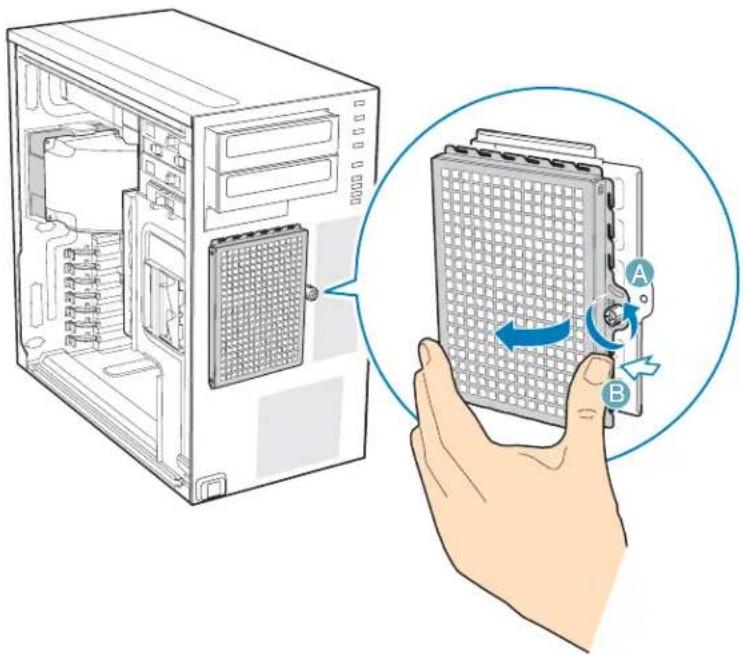
natural_image
Illustration of a computer tower with an open case and a hand holding a grid device labeled A and B, showing internal components and a blue circular arrow indicating rotation (no text or symbols beyond labels)TP01869
- Disconnect the data and power cables from the hard drive to be removed (see letter "A" in the following figure). Pull the drive latch forward (see letter "B") to unlatch the drive locking mechanism for the hard drive you want to remove.
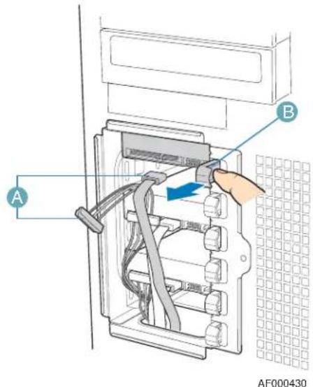
Figure 32. Preparing Fixed Hard Drive for Removal
- Slide the hard drive out of the fixed hard drive cage and place on an anti-static surface. If replacing the hard drive, see "Installing a Fixed Hard Drive" for instructions.
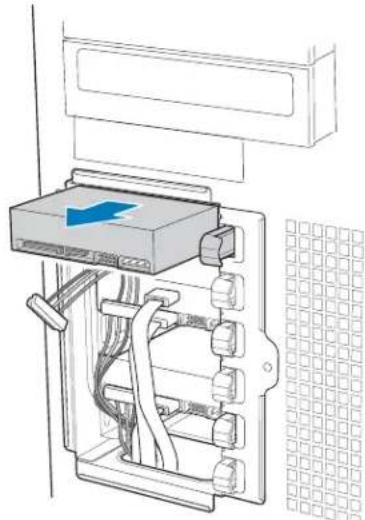
natural_image
Diagram of an electrical switch or server rack with cable and socket, no text or symbols presentAF000431
Figure 33. Removing Fixed Hard Drive from Drive Bay
- Re-attach the drive cage EMI shield to the chassis and tighten the thumb screw.
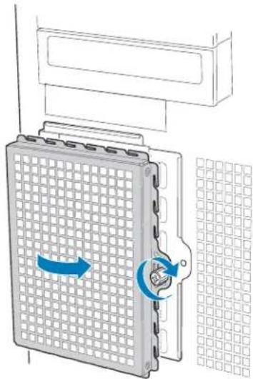
natural_image
Diagram of a grid-based device with directional arrows indicating rotation or movement (no text or symbols present)AF000315
Figure 34. Re-installing Drive Cage EMI Shield
-
Re-install the front bezel assembly. For instructions, see "Installing the Front Bezel Assembly"
-
Re-install the left side cover. For instructions, see "Installing the Left Side Cover"
-
Plug all peripheral devices and the AC power cable(s) into the server. Power up the server.
Installing or Removing a DVD-ROM or CD-ROM Drive
Caution: CD-ROM and DVD-ROM drives are NOT hot swappable. Before removing or replacing the drive, you must first take the server out of service, turn off all peripheral devices connected to the system, turn off the system by pressing the power button, and unplug the AC power cord from the system or wall outlet.
Installing a DVD-ROM or CD-ROM Drive
- Observe the safety and ESD precautions listed in Appendix A, "Safety Information".
- Power down the server and unplug all peripheral devices and the AC power cable.
- Remove the left side cover. For instructions, see "Removing the Left Side Cover".
- Remove the front bezel assembly. For instructions, see "Removing the Front Bezel Assembly".
- Remove the EMI shield from the 5.25-in device drive bay (see letter "A" in the following figure). Move latch to the "unlock" position (see letter "B").
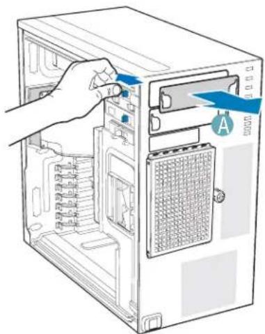
natural_image
Illustration of a desktop computer tower with a hand inserting a switch to the left panel (no text or symbols visible)TP01063
Figure 35. Removing 5.25-in Drive EMI Shield
- Insert CD-ROM or DVD-ROM drive into the 5.25-in device drive bay (see letter "C" in the following figure). Line up holes in CD-ROM drive with holes in chassis (see letter "D"). Move latch to the "lock" position (see letter "E"). Connect power (P3 or P4 connector from the power supply) and data cables to the rear of the CD-ROM or DVD-ROM drive (see letter "F").
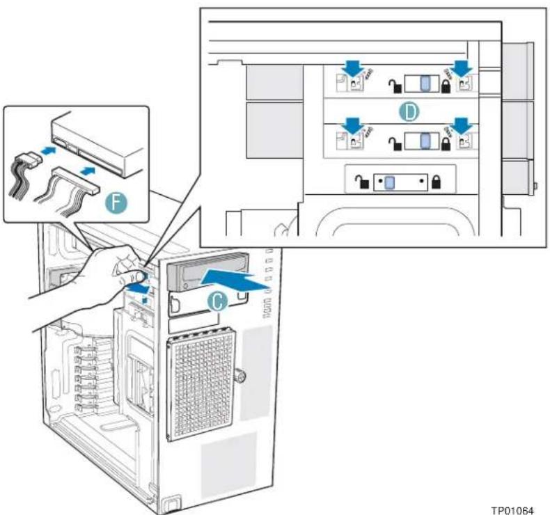
Figure 36. Installing CD-ROM or DVD-ROM Drive
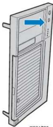
- If necessary, remove the filler panel from the front bezel assembly.
natural_image
Diagram of a server rack with ventilation slots and a blue arrow indicating direction (no text or symbols)- Reinstall the front bezel assembly. For instructions, see "Installing the Front Bezel Assembly".
- Reinstall the left side cover. For instructions, see "Installing the Left Side Cover".
- Reconnect all peripheral devices and the AC power cable(s). Power up the server.
Removing a CD-ROM or DVD-ROM Drive
- Observe the safety and ESD precautions listed in Appendix A, "Safety Information".
- Power down the server and unplug all peripheral devices and the AC power cable.
- Remove the chassis cover. For instructions, see "Removing the Left Side Cover".
- Remove the Front Bezel Assembly. For instructions, see "Removing the Front Bezel Assembly".
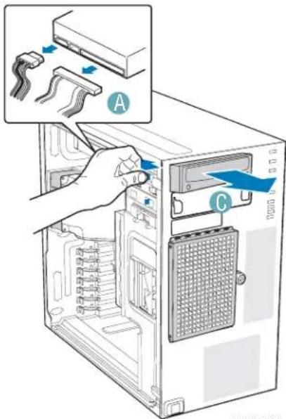
- Disconnect the power and data cables from the rear of the CD-ROM or DVD-ROM drive (see letter "A" in the following figure). Move latch to the "unlock" position (see letter "B"). Slide CD-ROM or DVD-ROM drive out of the Device Drive Bay (see letter "C").
TP02047
Figure 37. Removing CD-ROM or DVD-ROM Drive
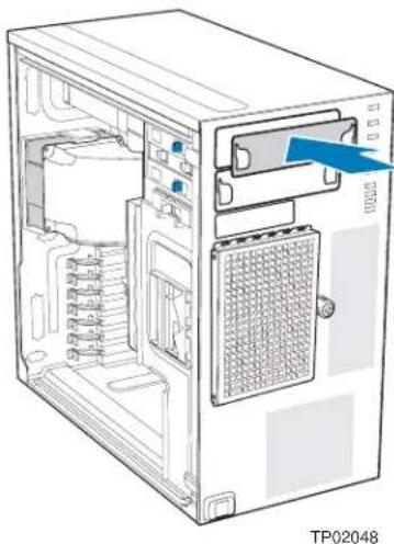
- If reinstalling a new CD-ROM or DVD-ROM drive, see "Installing a DVD-ROM or CD-ROM Drive" for instructions. If not replacing the drive, reinstall the EMI shield and front bezel filler panel, if available.
natural_image
Diagram of a desktop computer tower showing internal components and ventilation slots (no text or labels)Figure 38. Installing 5.25-in Drive EMI Shield
- Reinstall the front bezel assembly. For instructions, see "Installing the Front Bezel Assembly".
- Reinstall the chassis cover. For instructions, see "Installing the Left Side Cover".
- Reconnect all peripheral devices and the AC power cable(s). Power up the server.
Installing the Removing PCI Add-in Boards
The following instructions describe how to install and remove a PCI add-in board in the Intel ^® Entry Server Chassis SC5299-E. These instructions are server board dependent. See your server board documentation to determine PCI add-in board compatibility.
Caution: Do not overload the server board by installing add-in boards that draw excessive current.
Caution: PCI add-in boards can be extremely sensitive to electric static discharge (ESD) and always require careful handling. After removing the add-in board from its protective wrapper or from the server board, place it component side up on a grounded, static-free surface or conductive foam pad. Do not slide the add-in board over any surface.
Installing PCI Add-in Boards
Note: You may want to install an operating system before installing any PCI add-in boards.
- Observe the safety and ESD precautions listed in Appendix A, "Safety Information".
-
Power down the server and unplug all peripheral devices and the AC power cable.
-
Remove the left side cover. For instructions, see "Removing the Left Side Cover".
- Open the back panel PCI Add-in Card Retention Device by pressing open from the inside of the chassis.
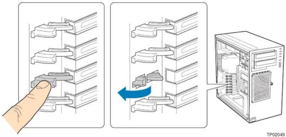
Figure 39. Opening PCI Add-in Card Retention Device
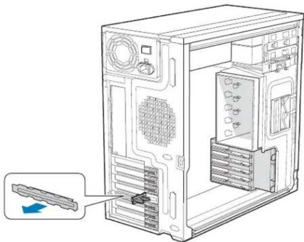
- Remove the PCI slot shield, if it has not already been removed, by pushing the shield out from the inside of the chassis.
natural_image
Technical line drawing of a computer tower internal structure showing ventilation, drive, and socket (no text or labels)TP01744
Figure 40. Removing PCI Slot Shield
-
Remove a PCI add-in board from its protective wrapper. Be careful not to touch the components or gold-edge connectors. Place board on an anti-static surface. Record the type and serial number of the add-in board in your equipment log. Set jumpers or switches on the board according to the manufacturer's instructions.
-
Hold the PCI add-in board by its top edge or upper corners. Firmly press the add-in board into an expansion slot on the server board (see letter "A" in the following figure). Close the back panel PCI Add-in Card Retention Device (see letter "B").
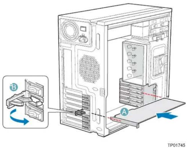
Figure 41. Installing PCI Add-in Board
- Repeat the previous steps until all PCI add-in boards are installed.
- Attach cables, if necessary.
- Reinstall the left side cover. For instructions, see "Installing the Left Side Cover".
- Reconnect all peripheral devices and the AC power cable. Power up the server.
Removing PCI Add-in Boards
Caution: PCI add-in boards can be extremely sensitive to electric static discharge (ESD) and always require careful handling. After removing the add-in board from its protective wrapper or from the server board, place it component side up on a grounded, static-free surface or conductive foam pad. Do not slide the add-in board over any surface.
- Observe the safety and ESD precautions listed in Appendix A, "Safety Information".
- Power down the server and unplug all peripheral devices and the AC power cable.
-
Remove the left side cover. For instructions, see "Removing the Left Side Cover".
-
Open the back panel PCI Add-in Card Retention Device by pressing open from the inside of the chassis.
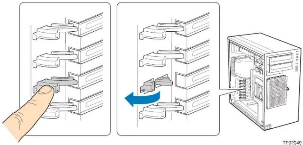
Figure 42. Opening PCI Add-in Card Retention Device
-
Disconnect any cables that may be attached to the PCI add-in board that needs to be removed.
-
Firmly grab the PCI add-in board by its top edge or upper corners and remove from the expansion slot on the server board (see letter "A" in the following figure). Place the removed add-in board in an anti-static protective wrapper. Close the back panel PCI Add-in Card Retention Device (see letter "B").
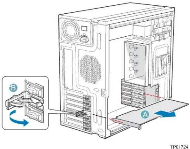
Figure 43. Removing PCI Add-in Board
- If available, replace the PCI slot shield by pressing the slot shield into the opening on the chassis.
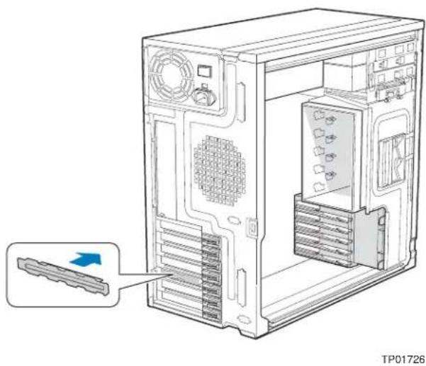
natural_image
Technical line drawing of a computer tower internal structure with ventilation slots and ventilation grilles (no text or symbols)Figure 44. Replacing PCI Slot Shield
-
Reinstall the left side cover. For instructions, see "Installing the Left Side Cover".
-
Reconnect all peripheral devices and the AC power cable(s). Power up the server.
Replacing the Front Panel Board
Your server must be operated with a front panel board installed.
Caution: The front panel board is NOT hot swappable. Before removing or replacing the front panel board, you must first take the server out of service, turn off all peripheral devices connected to the system, turn off the system by pressing the power button, and unplug the AC power cord from the system or wall outlet.
-
Observe the safety and ESD precautions listed in Appendix A, "Safety Information".
-
Power down the server and unplug all peripheral devices and the AC power cable.
-
Remove the left side cover. For instructions, see "Removing the Left Side Cover"
-
Remove the front bezel assembly if it is installed. For instructions, see "Removing the Front Bezel Assembly".
-
Remove the two screws (see letter "A" in the following figure") securing the right side cover to the chassis. Lift the right side cover off the chassis.
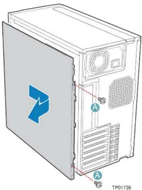
Figure 45. Removing Right Side Cover from Chassis
- Remove the three screws securing the front panel board to the chassis.
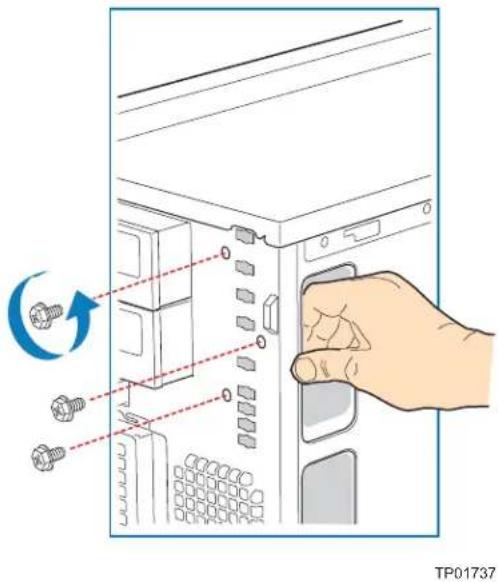
Figure 46. Unattaching Front Panel Board from Chassis
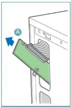
- Carefully remove the front panel board through the opening in the left side of the chassis (see letter "A" in the following figure). Disconnect the front panel cable (see letter "B") and the chassis intrusion cable (see letter "C") from the front panel board.
natural_image
Diagram of a computer tower with a green clipboard and a blue arrow labeled 'A' pointing to the screen (no text or symbols on the diagram itself)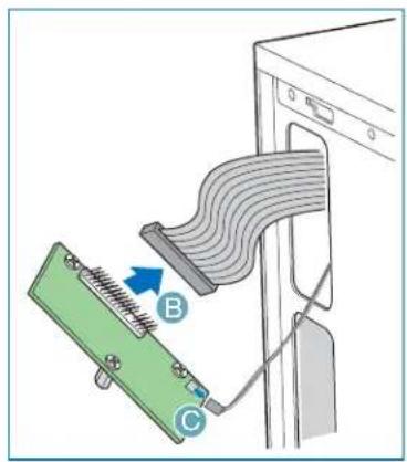
AF000432
Figure 47. Removing Front Panel Board from Chassis
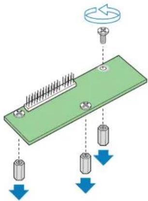
- Remove standoffs from old front panel and install on new front panel.
TP02000
Figure 48. Removing Standoffs from Front Panel
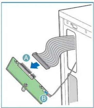
- Attach the front panel cable (see letter "A" in the following figure) and the chassis intrusion cable (see letter "B") to the new front panel board. Slide the new front panel board through the opening in the left side of chassis (see letter "C").
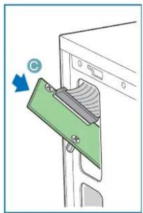
natural_image
Diagram of a computer tower with a green clipboard and a blue arrow indicating rotation (no text or symbols)AF000433
Figure 49. Installing Front Panel Board in Chassis
- Use one hand to align the front panel board in position inside the chassis. With your other hand, tighten the three screws to secure the front panel board to the front of the chassis.
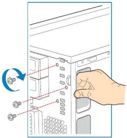
TP01740
Figure 50. Positioning Front Panel Board in Chassis
- Reinstall the right side cover. Reinstall the two screws.
Warning: This chassis must be operated with the right side cover installed to ensure proper cooling.
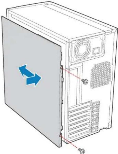
natural_image
Diagram of a computer tower with directional arrows indicating left and right motion (no text or symbols)TP01741
Figure 51. Re-installing Right Side Cover on Chassis
- Reinstall the front bezel assembly. For instructions, see "Installing the Front Bezel Assembly".
- Reinstall the left side cover. For instructions, see "Installing the Left Side Cover"
- Reconnect all peripheral devices and the AC power cable. Power up the server.
Replacing a System Fan
Caution: The system fan for the Intel ^® Entry Server Chassis SC5299-E is NOT hot swappable. Before removing or replacing a fan, you must first take the server out of service, turn off all peripheral devices connected to the system, turn off the system by pressing the power button, and unplug the AC power cord from the system or wall outlet.
- Observe the safety and ESD precautions listed in Appendix A, "Safety Information".
- Power down the server and unplug all peripheral devices and the AC power cable.
-
Remove the left side cover. For instructions, see "Removing the Left Side Cover".
-
Remove the fan duct /system fan assembly.
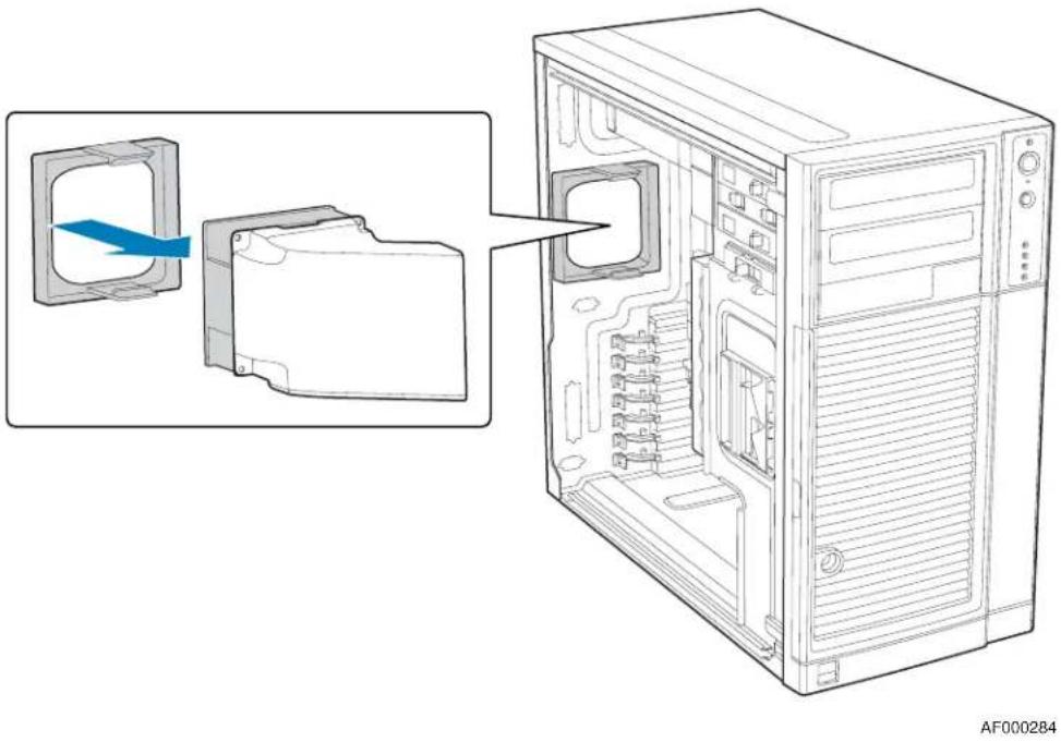
natural_image
Diagram of a computer tower internal structure showing internal components and an open base, with no visible text or symbols.Figure 52. Removing Fan Duct / System Fan Assembly
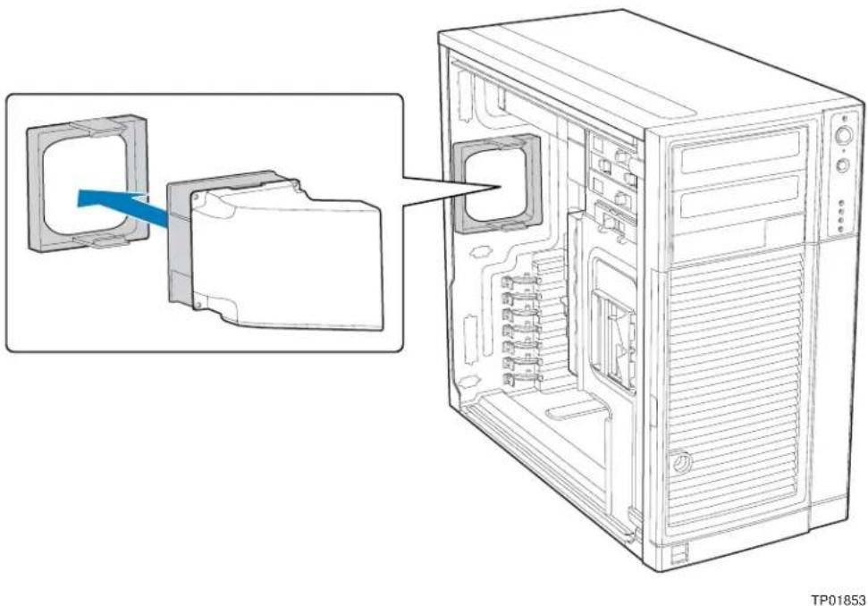
- Re-install the fan duct / system fan assembly.
natural_image
Diagram of a desktop computer tower showing internal components and a close-up of the folder (no text or symbols present)Figure 53. Re-installing Fan Duct / System Fan Assembly
- Reconnect the fan cable to the server board. Refer to the User Guide that came with your server board for connection location.
- Install the left side cover. For instructions, see "Installing the Left Side Cover".
- Plug all peripheral devices and the AC power cable into the server. Power up the server.
Replacing a Fixed Power Supply
Warning: Hazardous conditions, power supply: Hazardous voltage, current, and energy levels are present inside the power supply. There are no user-serviceable parts inside it; servicing of the power supply should only be done by technically qualified personnel.
Caution: The fixed power supply is NOT hot swappable in the DP and WS models of the Intel® Entry Server Chassis SC5299-E. Before removing or replacing the fixed power supply, you must first take the server out of service, turn off all peripheral devices connected to the system, turn off the system by pressing the power button, and unplug the AC power cord from the system or wall outlet.
To replace a fixed power supply, use the following instructions:
- Observe the safety and ESD precautions listed in Appendix A, "Safety Information"
- Power down the server and unplug all peripheral devices and the AC power cable.
- Remove the left side cover. For instructions, see "Removing the Left Side Cover".
- Disconnect all internal power cables from chassis components and server board.
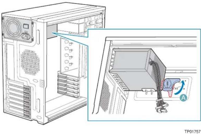
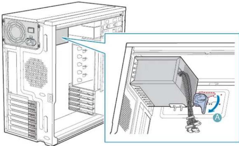
- Rotate the blue locking mechanism (see letter "A" in the following figure to the open position.
natural_image
Technical diagram showing a computer tower with ventilation slots and a close-up of the internal components (no text or symbols present)Figure 54. Unlocking Fixed Power Supply from Chassis
- Once the fixed power supply is loose, push the power supply against the blue locking mechanism and then lift the power supply out of the chassis.
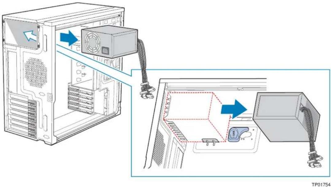
Figure 55. Removing Fixed Power Supply from Chassis
- Insert new fixed power supply in chassis. Ensure that the blue locking mechanism is still in the open position. Make sure that the new fixed power supply rests on the small metal shelf on the side wall of the chassis (see letter "A" in the following figure).
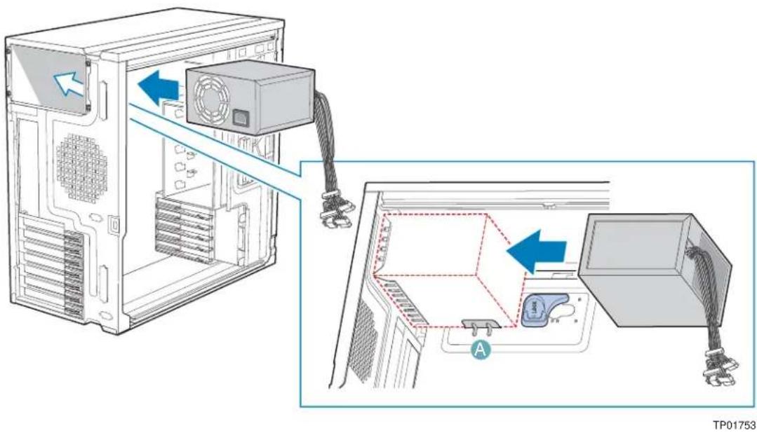
Figure 56. Inserting Fixed Power Supply in Chassis
- Rotate the blue locking mechanism to the locked position (see letter "A" in the following figure).
natural_image
Technical line drawing of a computer tower with internal components and a close-up view showing internal wiring (no text or symbols)TP01755
Figure 57. Locking Fixed Power Supply into Chassis
- Route and connect the P1, P2, and P14 cables to the server board. Refer to the Intel ^® Server Board Quick Start User's Guide or User Guide that came with your Intel ^® server board for appropriate power connections.
- Route the P5 cable to the floppy drive.
- Route the P3 and P4 cables to the 5.25-in. removable media device bays and connect to installed devices.
- Route the P8, P9, P10, and P12 cables to the hard drive cage and connect power cables to installed devices.
- Install the left side cover. For instructions, see "Installing the Left Side Cover".
- Reconnect all peripheral devices and the AC power cable to the server. Power up the server.
Installing an Additional Hot Swap Power Supply Module (BRP configuration only)
Note: This install procedure only applies to a chassis with redundant power supply capability. DO NOT perform this install procedure if your chassis has a fixed power supply
Warning: Hazardous conditions, power supply: Hazardous voltage, current, and energy levels are present inside the power supply. There are no user-serviceable parts inside it; servicing of the power supply should be done only by technically qualified personnel.
-
Observe the safety and ESD precautions listed in Appendix A, "Safety Information".
-
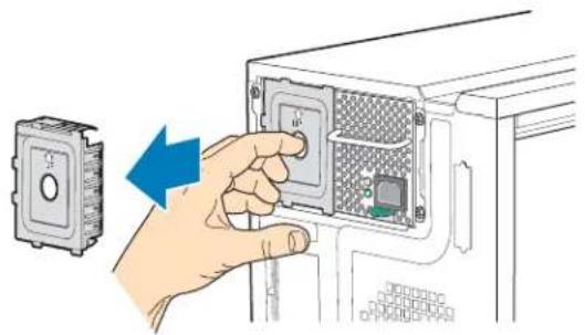
Insert finger into hole in middle of filler panel and remove filler panel from chassis.
natural_image
Illustration of a hand inserting a component into a device panel, showing a blue arrow indicating the process (no text or symbols present)TP00916
Figure 58. Removing Power Supply Filler Panel
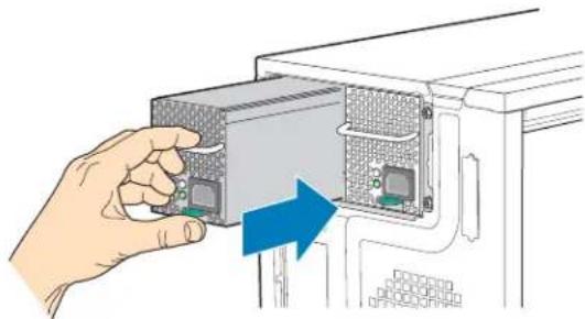
- Insert new hot swap power supply module until it clicks into place.
natural_image
Hand inserting a computer drive into a rack, showing internal components and a blue arrow indicating the process (no text or symbols present)TP00917
Figure 59. Inserting Additional Hot Swap Power Supply Module
Replacing a Hot Swap Power Supply (BRP configuration only)
Warning: Hazardous conditions, power supply: Hazardous voltage, current, and energy levels are present inside the power supply. There are no user-serviceable parts inside it; servicing of the power supply should be done only by technically qualified personnel.
- Observe the safety and ESD precautions listed in Appendix A, "Safety Information".
- Remove power cable from defective power supply.
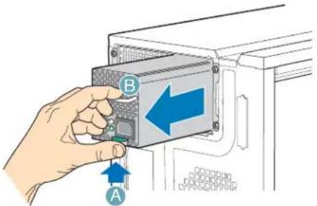
- Press up on green latch (see letter "A" in the following figure) while pulling on handle (see letter "B") to remove hot swap power supply from chassis.
TP00856
Figure 60. Removing Hot Swap Power Supply Module from Chassis
- Insert new hot swap power supply module.

natural_image
Hand inserting a device into a container with an arrow indicating direction (no text or symbols present)TP00854
Figure 61. Inserting Hot Swap Power Supply Module in Chassis
- Connect power cable to replaced hot swap power supply.
Replacing a Hot Swap Power Supply Cage (BRP configuration only)
Warning: Hazardous conditions, power supply: Hazardous voltage, current, and energy levels are present inside the power supply. There are no user-serviceable parts inside it; servicing of the power supply should be done by technically qualified personnel.
-
Observe the safety and ESD precautions listed in Appendix A, "Safety Information".
-
Power down the server and unplug all peripheral devices and the AC power cable.
-
Remove the left side cover. For instructions, see "Removing the Left Side Cover".
-
Press up on green latch (see letter "A") while pulling on handle to remove hot swap power supply module from chassis.
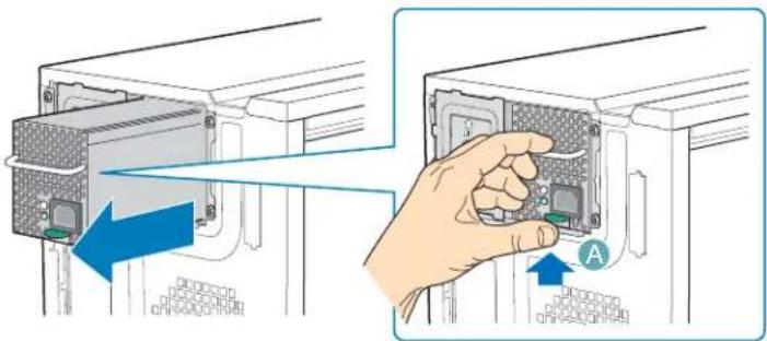
TP01765
Figure 62. Removing Hot Swap Power Supply Module
-
Remove second (redundant) hot swap power supply module (or filler panel), if one is present.
-
Disconnect all internal power cables from chassis components and server board.
-
Remove two internal screws (see letter "A" in the following figure) securing hot swap power supply cage to chassis.
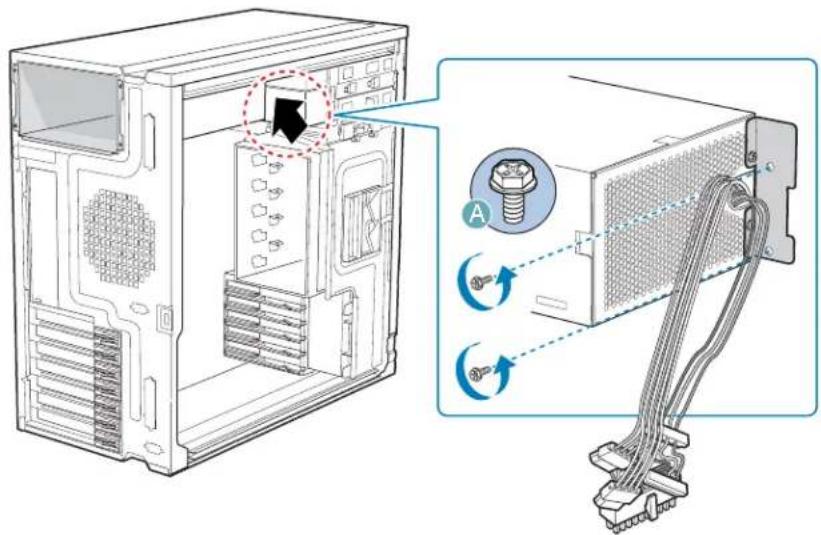
TP01761
Figure 63. Detaching Hot Swap Power Supply Cage from Inside of Chassis
- Remove five external screws securing back of power supply cage to chassis. Slide the power supply cage out of the chassis.
Note: You may have to work the power cables through slot sopenings with your free hand as you remove the power supply cage from the chassis.
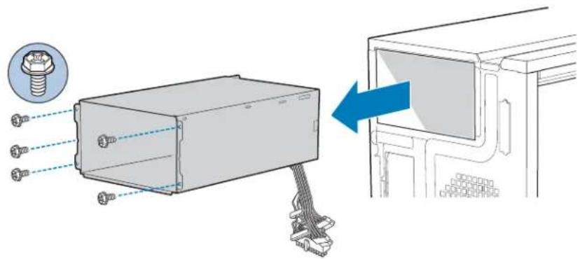
TP01762
Figure 64. Detaching Hot Swap Power Supply Cage from Rear of Chassis
- Remove the two screws (see letter "A" in the following figure) attaching the rear support bracket to the old power supply cage. Remove the rear support bracket (see letter "B").
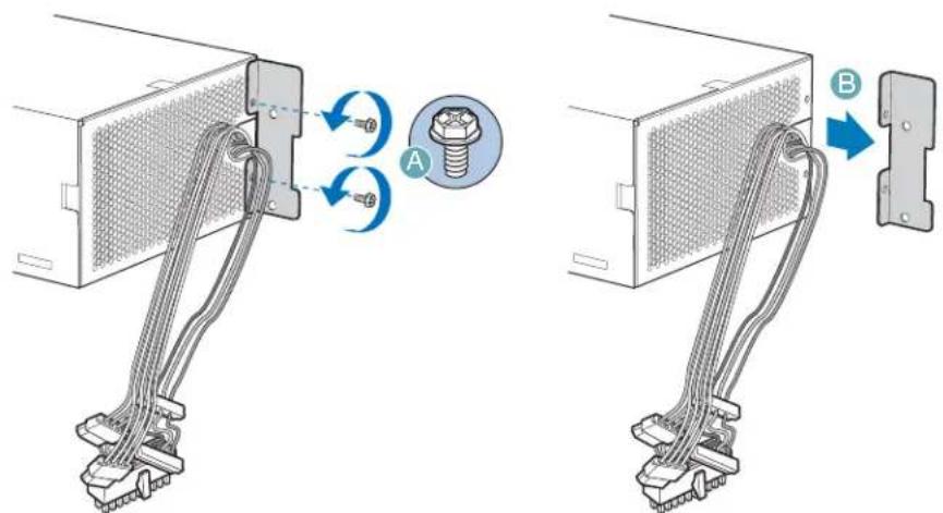
TP01764
Figure 65. Removing Rear Support Bracket from Hot Swap Power Supply Cage
- Attach the rear support bracket to the new power supply cage with the two screws removed from the previous step.
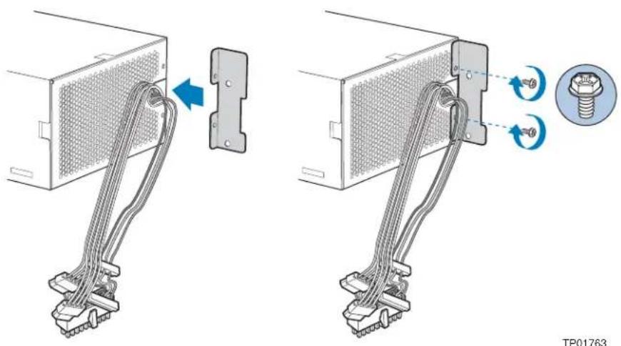
natural_image
Diagram showing two cable installation steps with a screw and nut, no text or symbols presentFigure 66. Attaching Rear Support Bracket to Power Supply Cage
- Insert new hot swap power supply cage into chassis. Secure back of hot swap power supply cage to chassis with five screws.
Note: Ensure that you route the power supply cables through the power supply opening in the chassis first before inserting the power supply cage.
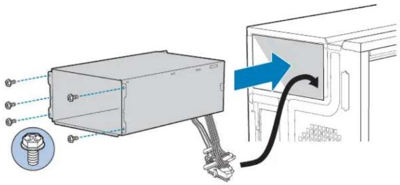
TP01766
Figure 67. Securing Hot Swap Power Supply Cage to Rear of Chassis
- Secure inside panel of hot swap power supply cage to chassis with two screws.
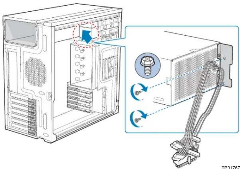
Figure 68. Securing Hot Swap Power Supply Cage to Inside of Chassis
-
Route the P1, P2, and P14 power cables to the server board and connect to appropriate connectors. Refer to the Intel ^® Server Board Quick Start User's Guide or User Guide that came with your Intel ^® server board for the location of power connections.
-
Route the P8, P9, P10, and P12 cables to the hard drive cage and connect power cables to any installed devices.
-
Route the P3 and P4 cables to the 5.25-in. removable media device bays and connect to any installed devices.
-
Route the P5 cable to the floppy drive, if installed.
-
Reinstall the hot swap power supply module(s). The power supply module(s) will click into place when properly seated.
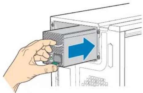
natural_image
Hand inserting a device into a rack, showing a blue arrow pointing to the internal component (no text or symbols present)TP01768
Figure 69. Re-installing Hot Swap Power Supply Module(s)
-
Install the left side cover. For instructions, see "Installing the Left Side Cover".
-
Reconnect all peripheral devices and the AC power cable(s) to the server. Power up the server.
Installing Feet for a Pedestal-configured Chassis
Note: Do not install feet on your Intel ^ Entry Server Chassis SC5299-E if it is to be installed in a rack. Only install feet on a pedestal-configured chassis.
-
Observe the safety and ESD precautions listed in Appendix A, "Safety Information".
-
Power down the server and unplug all peripheral devices and the AC power cable.
-
Lay the chassis down on its right side.
-
Insert rubber foot into chassis hole (see letter "A" in the following figure). Secure foot to chassis by inserting a pin through the rubber foot (see letter "B"). Repeat process for remaining feet.
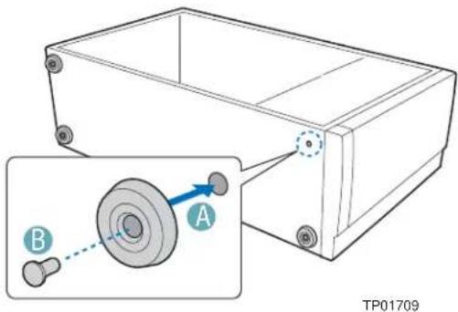
Figure 70. Installing Feet on Chassis
-
Put chassis in the upright position.
-
Reconnect all peripheral devices and the AC power cable to the server. Power up the server.
3 Hot Swap Drive Cage Upgrade Install Instructions (optional)
The fixed hard drive cage that ships with your Intel ^® Entry Server Chassis SC5299-E is upgradeable to a hot swap drive cage with a SCSI or SAS/SATA backplane. See your Intel Representative for ordering information.
Up to six hot swap hard drives can be installed in the optional hot swap drive cage. Power requirements for each individual hard drive may limit the maximum number of drives that can be integrated into the server chassis.
Note: The Intel ^ Entry Server Chassis SC5299-E does not support all hard drives. See “Additional Information and Software” for a web link to a list of supported hard drives.
Before You Begin
Before working with your server product, review the important safety information listed in Appendix A, “Safety Information”.
Kits Required
- A hot swap conversion kit (part number: APP3HSDBKIT).
- Either a hot swap drive cage kit with a SCSI backplane (part number: AXX6SCSIDB) or a hot swap drive cage kit with a SAS/SATA backplane without expander (part number AXX6DRV3G) or a SAS/SATA backplane with expander (part number AXX6DRV3GEXP).
Tools and Supplies Needed
- Phillips* (cross head) screwdriver (#1 bit and #2 bit)
- Needle-nosed pliers
- Anti-static wrist strap and conductive foam pad (recommended)
System References
All references to left, right, front, top, and bottom assume the reader is facing the front of the chassis as it would be positioned for pedestal operation.
Installing a Hot Swap Hard Drive Cage with a SAS/SATA or SCSI Backplane
- Observe the safety and ESD precautions listed in Appendix A, "Safety Information".
- Power down the server and unplug all peripheral devices and the AC power cable.
- Remove the left side cover. For instructions, see "Removing the Left Side Cover".
- Remove the front bezel assembly. For instructions, see "Removing the Front Bezel Assembly".
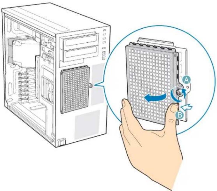
- Loosen the thumb screw and remove the fixed drive cage EMI shield.
natural_image
Illustration of a computer tower with an open case and a hand holding a grid-patterned device labeled A and B (no text or symbols on the device itself)TP01869
Figure 71. Removing Fixed Drive Cage EMI Shield from Chassis
-
Disconnect cables from any fixed hard drives and remove hard drives from fixed hard drive cage. For instructions on removing fixed hard drives, see "Removing a Fixed Hard Drive".
-
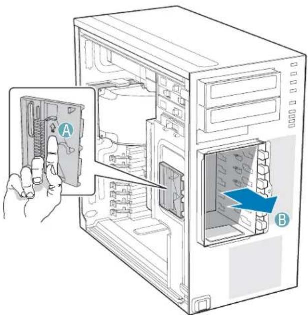
Push the blue plastic release mechanism upward to release the fixed hard drive cage (see letter "A" in the following figure). Once released, pull the fixed hard drive cage from the chassis (see letter "B").
TP02038
Figure 72. Removing Fixed Hard Drive Cage from Chassis
-
Gather together the components for the hot swap drive cage installation. You should have a hot swap drive cage with either a SAS/SATA or SCSI backplane, a side filler panel, a latch plate, a fan bracket, and a fan.
-
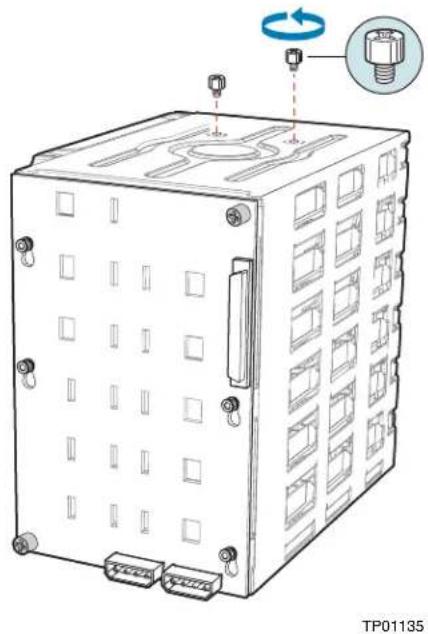
Remove the stud screws from the top of the hot swap drive cage.
natural_image
Technical line drawing of a server rack unit with connectors and a circular component, no text or symbols presentFigure 73. Removing Stud Screws from Hot Swap Drive Cage
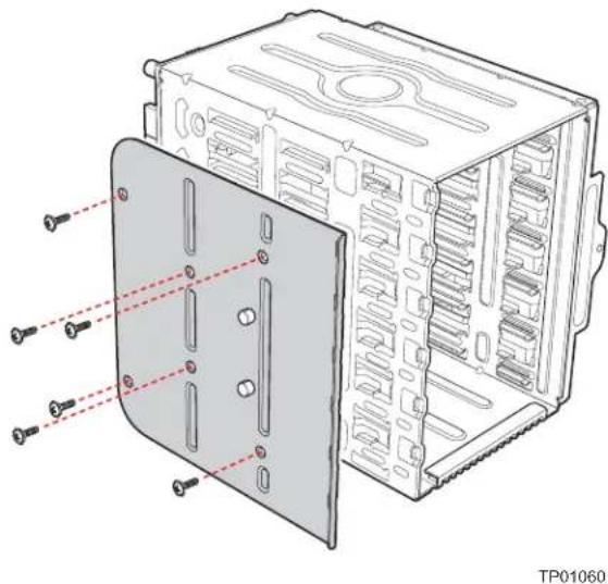
- Attach the latch plate to the left side of the hot swap drive cage.
natural_image
Technical line drawing of a computer case with screw annotations (no text or symbols present)Figure 74. Attaching Latch Plate to Hot Swap Drive Cage
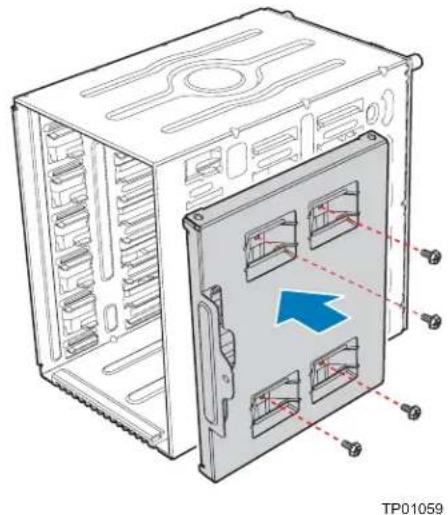
- Attach the side filler panel to the right side of the hot swap drive cage.
natural_image
Technical line drawing of a server rack cabinet with internal compartments and mounting points (no text or symbols)Figure 75. Attaching Filler Panel to Hot Swap Drive Cage
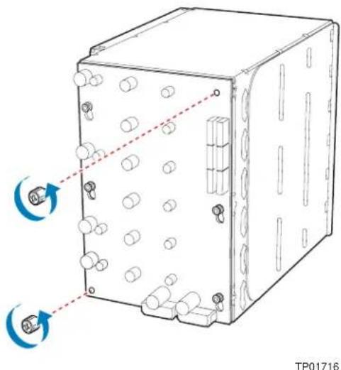
- Remove the two thumb screws that secure the backplane to the hot swap drive cage.
natural_image
Technical line drawing of a mechanical or electronic device with multiple ports and mounting holes, showing no text or symbols.Figure 76. Removing Thumb Screws from Backplane
- Align the fan bracket with the three pegs on the drive cage (see letter "A" in the following figure) and slide the fan bracket into position. Replace the two thumb screws (see letter "B").
Caution: The backplane may have slipped once the thumb screws were removed. Ensure that the backplane is positioned correctly before re-tightening the thumb screws.
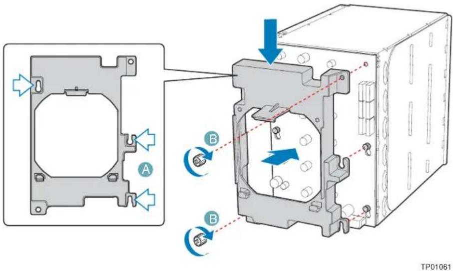
Figure 77. Attaching Fan Bracket to Hot Swap Drive Cage (SAS/SATA drive cage illustrated)
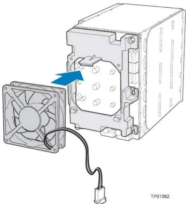
- Attach the fan to the fan bracket by placing two corners of the fan into the two holding slots on the fan bracket. Press the fan into the fan bracket until is clicks into place.
Caution: Ensure that the label and directional airflow arrow on fan are pointed out (away from the backplane).
natural_image
Diagram of a computer fan assembly with an external circuit board and cable, showing no text or symbols.Figure 78. Attaching Fan to Fan Bracket
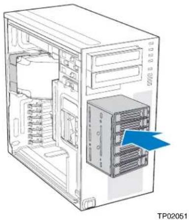
- Slide the drive cage into the drive bay slot on the chassis. You should hear a click when the blue plastic retention mechanism locks into place. Be sure to feed the fan cable through the slot first so that it exits through the back of the drive cage. Connect the fan cable to its connector on the server board.
natural_image
Diagram of a desktop computer tower showing internal components and a blue arrow pointing to a rack-mounted tower (no text or symbols present)Figure 79. Inserting Hot Swap Drive Cage into Chassis
-
Connect fan cable to the appropriate connector on the server board. See your server board documentation for information on the location of the fan cable connector.
-
Make backplane and server board/RAID controller card cable connections. Cable instructions will differ depending upon whether you are installing a SCSI or SAS/SATA hot swap drive cage. Refer to the documentation that came with your server board and/or RAID controller card for instructions on connecting backplane cables to your server board or RAID controller card.
Warning: It is critical that you connect the SAS/SATA data cables correctly from the SAS/SATA backplane to your server board or RAID controller card. Failure to do so may result in data loss.
Note: Connect the SES cable from the backplane to the RAID card (if one is installed).
a. If you are installing a six-drive SCSI hot swap drive cage:
i. Connect the two power cables (see letter "A" in the following figure) to the two power cable connectors on the SCSI backplane.
ii. Connect the SCSI data cable (see letter "B") to the SCSI connector on the SCSI backplane.
iii. (Optional, dependent on server board installed) Connect the IPMB header (see letter "C") to the IPMB connector on the SCSI backplane.
iv. Connect the fan power to the server board. For the Intel® Server Board S5000VSA, use FAN1. For other Intel® server boards, refer to the Quick Start User's Guide that came with the server board.
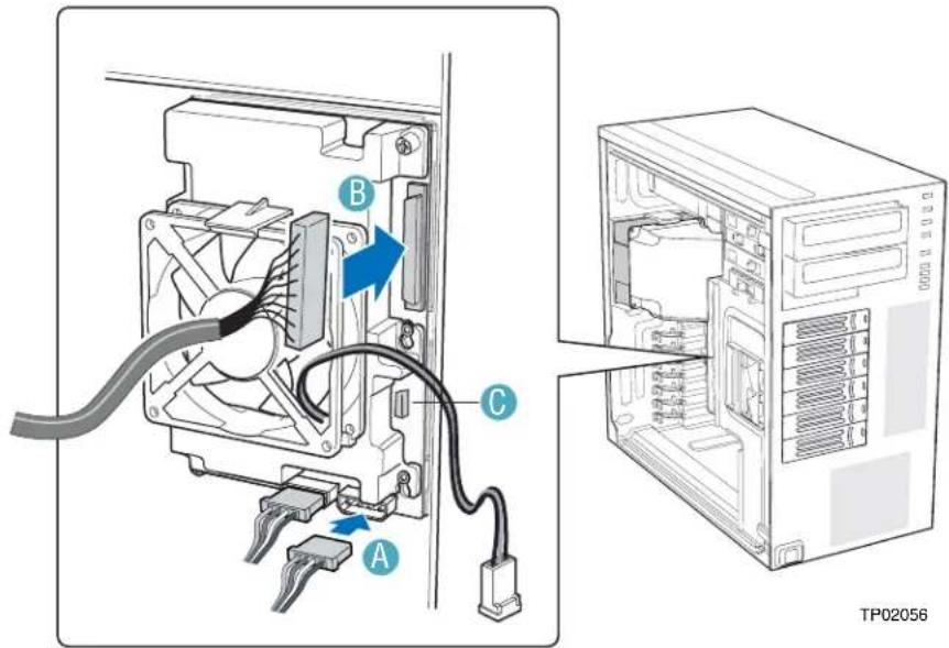
Figure 80. Cabling the SCSI Hot Swap Drive Cage
Hot Swap Drive Cage Upgrade Install Instructions (optional)
b. If you are installing a six-drive SAS/SATA hot swap drive cage:
Warning: It is critical that you connect the SAS/SATA data cables correctly from the SAS/SATA backplane to your server board or RAID Controller card. Failure to do so may result in data loss.
Note: The SAS/SATA cables are labeled to correspond with each drive. Make sure to connect the cables correctly to avoid confusion later.
The SAS/SATA connectors are laid out as follows on the SAS/SATA backplane.
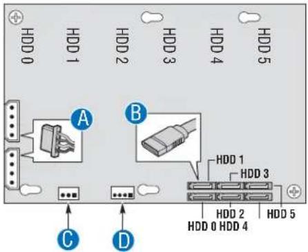
AF00450
| A. Power cable |
| B. Data Cable |
| C. IPMB |
| D. SES (not available in AXX6DRV3GEXP) |
Figure 81. Layout of Cable Connectors on the SAS/SATA Backplane (Backplane without expander shown)
c. If you are installing a SAS/SATA hot swap backplane without expander
Warning: SATA controllers cannot be used with an expander backplane.
i. Connect the two power cables (see letter "A" in the following figure) to the power cable connectors on the SAS/SATA backplane.
ii. Connect a SAS/SATA data cable (see letter "B") to each appropriate SAS/SATA connector on the SAS/SATA backplane.
iii. Connect the IPMB cable (see letter "C").
iv. Connect the SES cable (see letter "D").
v. Connect the fan power to the server board. For the Intel® Server Board S5000VSA, use FAN1. For other Intel® server boards, refer to the Quick Start User's Guide that came with the server board.
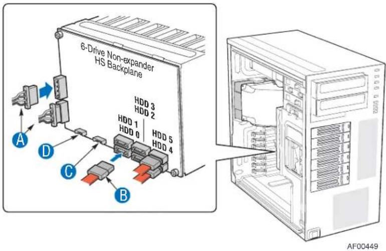
Figure 82. Making Six-drive SAS/SATA Hot-Swap Drive Cage Backplane without Expander Connections (fan bracket not shown in the illustration for clarity)
d. If you are installing a SAS/SATA hot swap backplane with expander
Warning: SATA controllers cannot be used with an expander backplane.
i. Connect the two power cables (see letter "A" in the following figure) to the power cable connectors on the SAS/SATA backplane.
ii. Connect a SAS/SATA data cable (see letter "B") to each appropriate SAS/SATA connector on the SAS/SATA backplane.
iii. Connect the IPMB cable (see letter "C").
iv. Connect the fan power to the server board. For the Intel® Server Board S5000VSA, use FAN1. For other Intel® server boards, refer to the Quick Start User's Guide that came with the server board.
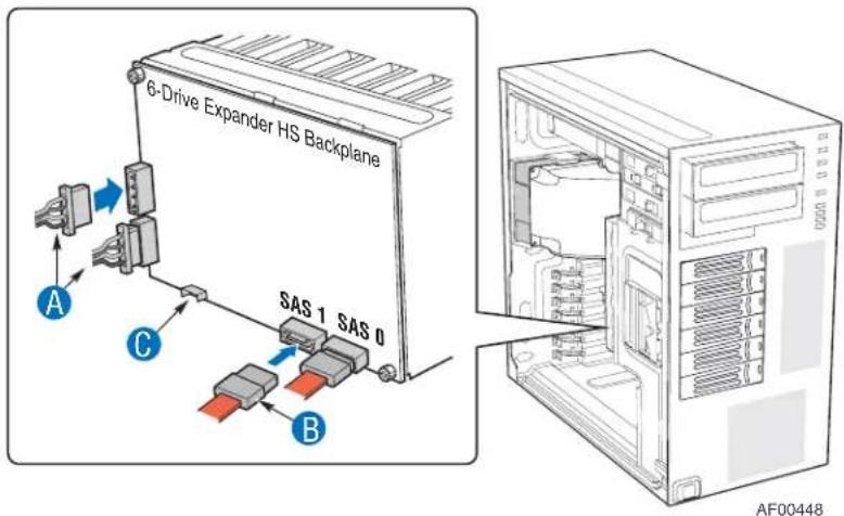
Figure 83. Making Six-drive Hot Swap Drive Cage Backplane with Expander Connections (fan bracket not shown in the illustration for clarity)
-
Install the hot swap hard drives. For instructions, see "If you are installing a six-drive SCSI hot swap drive cage:".
-
Install the front bezel assembly. For instructions, see "Installing the Front Bezel Assembly".
-
Install the left side cover. For instructions, see "Installing the Left Side Cover".
-
Plug all peripheral devices and the AC power cable into the server.
Installing a Hot Swap Hard Drive
Note: The following set of instructions is only applicable if you have replaced the fixed hard drive cage that shipped with your chassis with an optional hot swap SCSI or SAS/SATA hard drive cage. If you are replacing a fixed hard drive, see “Removing a Fixed Hard Drive” for instructions.
Note: The Intel ^ Entry Server Chassis SC5299-E does not support all hard drives. See "Additional Information and Software" for an Internet link to a list of supported hard drives.
- Open the drive bay access door.
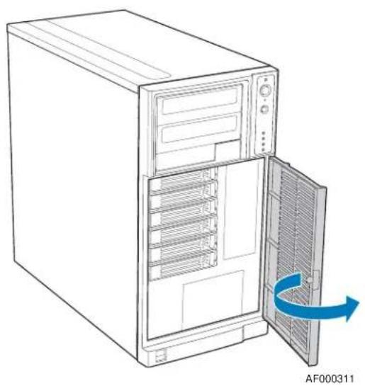
natural_image
Line drawing of a desktop computer tower with an open door and a blue arrow indicating rotation (no text or symbols on the diagram itself)Figure 84. Opening Drive Bay Access Door
- Remove a drive carrier from the hot swap drive cage. Press in on the green latch (see letter "A" in the following figure) at the end of the drive carrier to disengage the drive carrier from the drive cage. Pull out on the black lever (see letter "B") to push the drive carrier partially out of the drive cage. Slide the drive carrier all the way out of the drive cage.
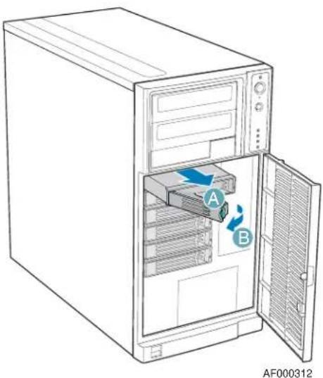
Figure 85. Releasing Drive Carrier from Hot Swap Drive Cage
- Remove the four screws that attach the plastic retention device to the drive carrier. Two screws are located on each side of the retention device.
Note: Store the plastic retention device for future use.
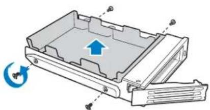
natural_image
Technical diagram of a mechanical device with an upward arrow indicating motion or force, showing internal components and mounting points (no text or symbols present)TP00928
Figure 86. Removing Retention Device from Drive Carrier
-
Remove the hard drive from its wrapper and place it on an anti-static surface.
-
Set any jumpers and/or switches on the drive according to the drive manufacturer's instructions.
-
With the drive circuit-side down, position the connector end of the drive so that it is facing the rear of the drive carrier.
-
Align the holes in the drive to the holes in the drive carrier and attach the drive to the carrier with the screws that were formerly attached to the plastic retention device.
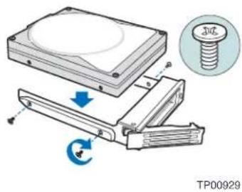
Figure 87. Installing Hard Drive into Drive Carrier
- With the black lever in the fully open position, insert the drive carrier into the hot swap drive cage. The green latch at the front of the drive carrier must be to the left of the drive cage. Do not push on the black drive carrier lever until the lever begins to close by itself. Once the black drive carrier lever begins to close by itself, push on it to lock the drive carrier into place.
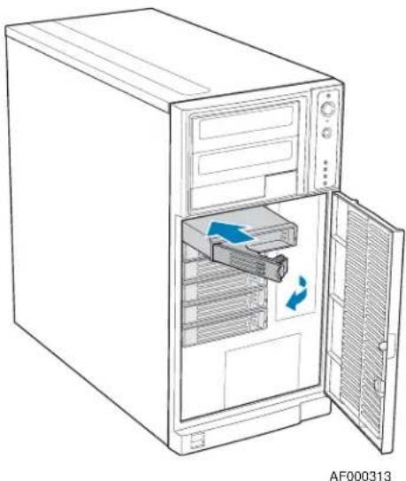
natural_image
Line drawing of a desktop computer tower with an open door and internal storage unit (no text or symbols)Figure 88. Re-installing Drive Carrier in Hot Swap Drive Cage
Hot Swap Drive Cage Upgrade Install Instructions (optional)
- Close the drive bay access door.
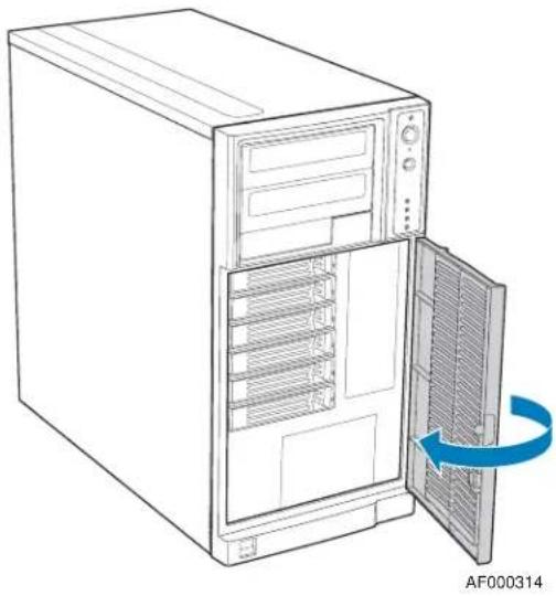
natural_image
Line drawing of a desktop computer tower with an open door and ventilation slots, showing internal rack layout (no text or symbols)Figure 89. Closing Drive Bay Access Door
Removing a Hot-swap Hard Drive
- Open the drive bay access door.
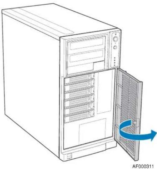
natural_image
Line drawing of a desktop computer tower with an open door and ventilation slots, showing internal rack layout (no text or symbols)Figure 90. Opening Drive Bay Access Door
- Press in on the green latch at the front of the drive carrier (see letter "A" in the following figure). Pull out on the black lever (see letter "B") to slide the drive carrier from the hot swap drive cage.
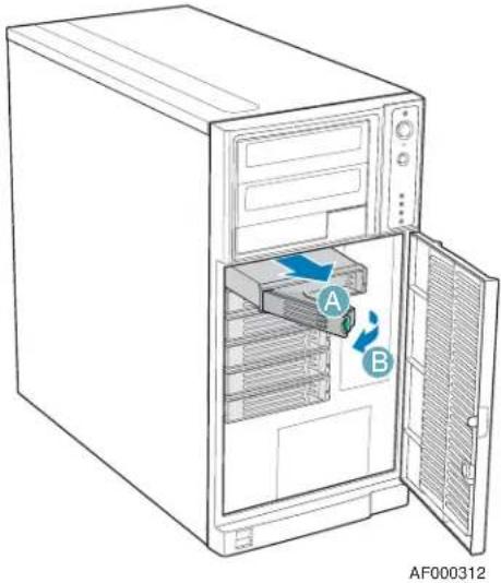
Figure 91. Removing Drive Carrier from Hot Swap Drive Cage
- Remove the four screws that attach the hard drive to the drive carrier. Lift the drive from the carrier. Store the old drive in an anti-static bag.
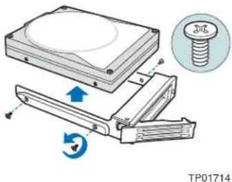
Figure 92. Removing Hard Drive from Drive Carrier
- Remove the new drive from its anti-static bag and place in the drive carrier. With the drive circuit-side down, position the connector end of the drive so that it is facing the rear of the drive carrier. Align the holes in the drive to the holes in the drive carrier and attach the drive to the carrier with the screws removed in the previous step.
Note: If you are not installing a new drive, place a plastic retention device into the drive carrier, using the four screws you removed from the hard drive.
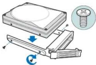
TP00929
Figure 93. Installing Hard Drive in Drive Carrier
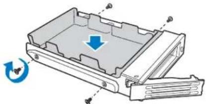
natural_image
3D diagram of a mechanical device with internal components and directional arrows indicating motion (no text or symbols)TP01713
Figure 94. Installing Plastic Retention Device in Drive Carrier
- With the black lever in the fully open position, slide the drive carrier into the chassis. The green latch must be to the left. Do not push on the black lever until the lever begins to close by itself. When the black lever begins to close by itself, push on it to lock the drive carrier into place.
Note: For proper airflow, the drive carrier must be replaced in the chassis, even if no hard drive is installed in it.
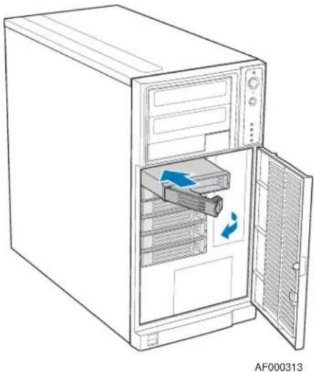
natural_image
Line drawing of a desktop computer tower with an open door and internal storage unit (no text or symbols)Figure 95. Re-installing Drive Carrier in Hot Swap Drive Cage
- Close the drive bay access door.
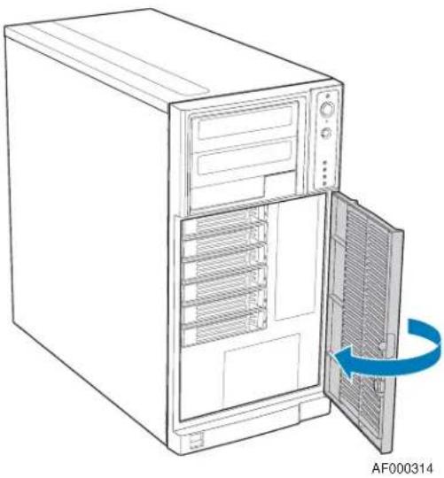
natural_image
Line drawing of a desktop computer tower with an open door and ventilation slots, showing internal rack layout (no text or symbols)Figure 96. Closing Drive Bay Access Door
Hot Swap Drive Cage Upgrade Install Instructions (optional)
4 Rack Mount Kit Install Instructions (optional)
The Intel ^® Entry Server Chassis SC5299-E can be configured as a rack-mount chassis when outfitted with the optional rack mount accessory kit.
Before You Begin
Before working with your server product, review the important safety information listed in Appendix A, “Safety Information”.
Tools and Supplies Needed
- Phillips* (cross head) screwdriver (#1 bit and #2 bit)
- Needle-nosed pliers
- Anti-static wrist strap and conductive foam pad (recommended)
System References
All references to left, right, front, top, and bottom assume the reader is facing the front of the chassis as it would be positioned for rack-mount operation.
Setting up a Rack-configured Chassis
- Observe the safety and ESD precautions listed in Appendix A, "Safety Information".
- Power down the server and unplug all peripheral devices and the AC power cable.
-
Lay the chassis down on its right side.
-
If installed, remove the chassis feet. Remove pin from rubber foot (see letter "A" in the following figure). Remove rubber foot from chassis hole (see letter "B"). Repeat process for remaining feet.
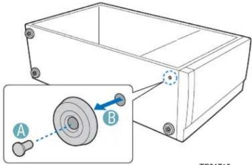
Figure 97. Removing Chassis Feet
- Remove the top side cover by pressing the latch and pushing back on the side cover to slide rearward and lift from chassis.
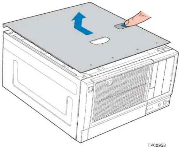
natural_image
Illustration of a computer oven with a hand pressing a button on top, showing internal structure and airflow direction (no text or symbols)Figure 98. Removing Top Side Cover from Chassis
- Remove any PCI add-in boards. Remove the PCI card guide by pressing in on the blue tabs (see letter "A" in the following figure) and pulling the PCI card guide outward (see letter "B").
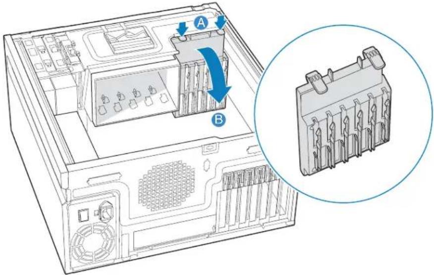
TP02001
Figure 99. Removing PCI Card Guide
- Remove plastic filler panel from chassis by pushing on interior tab (see letter "A" in the following figure) and sliding filler panel towards rear of chassis (see letter "B").
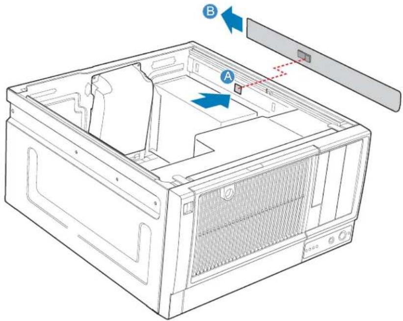
AF000285
Figure 100. Removing Plastic Filler Panel from Chassis
- Remove the three plastic plugs from left side of chassis.
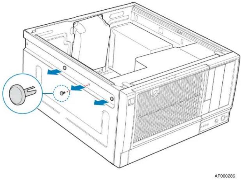
natural_image
Technical line drawing of a computer case with internal components and a magnified inset showing a key inserted into the case (no text or symbols present)Figure 101. Removing Plastic Plugs
- Remove two screws from left and right sides of chassis.
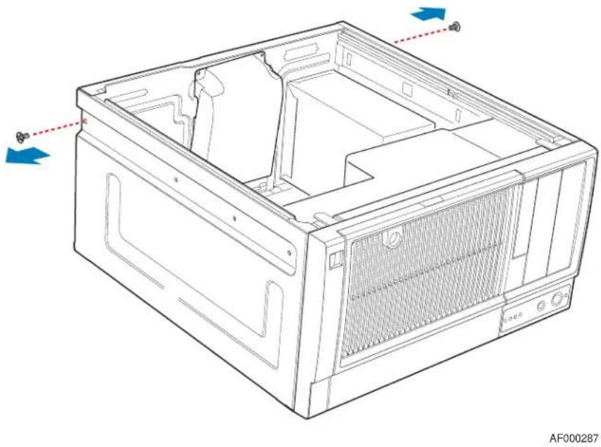
natural_image
Technical line drawing of a computer case with internal compartments and ventilation grilles (no text or symbols)Figure 102. Removing Rear Screws
- Remove four plastic plugs from top side cover.
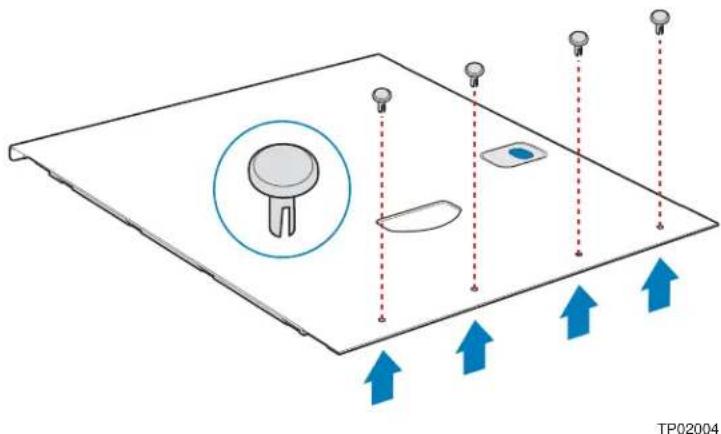
natural_image
Diagram of a device panel with labeled components and directional arrows indicating flow or movement (no text or symbols present)Figure 103. Removing Plastic Plugs from Top Side Cover
- Install rack handle on left side cover using four 6-32 screws.
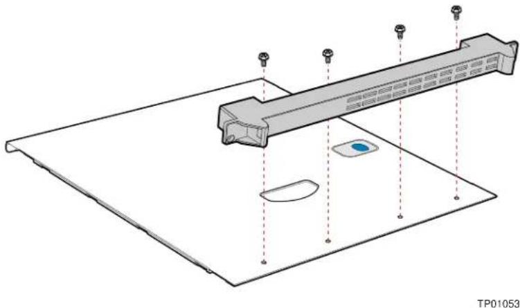
natural_image
Technical line drawing of a mechanical assembly with mounting holes and a central component (no text or symbols)Figure 104. Installing Rack Handle on Left Side Cover
- If removed, install front bezel assembly. Affix front panel label (see letter "A" in the following figure) to the front panel.
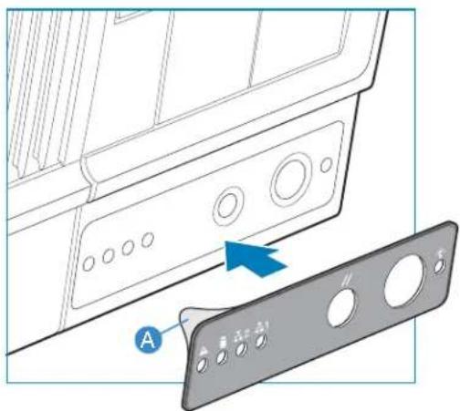
TP02005
Figure 105. Affixing Label to Front Panel
- Install top side cover on chassis.
Warning: This chassis must be operated with the left side cover installed to ensure proper cooling.
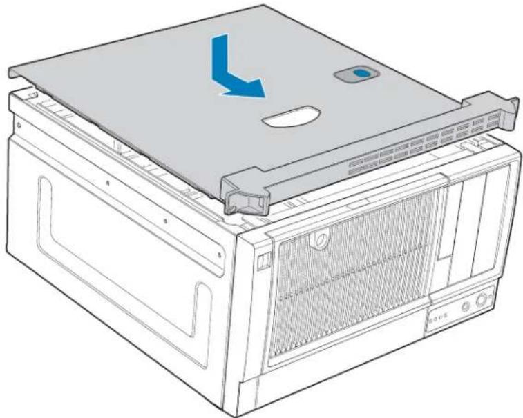
natural_image
Technical line drawing of a computer tower with ventilation grilles and a blue arrow indicating a component (no text or symbols present)TP01057
Figure 106. Installing Top Side Cover on Chassis
- Detach inner rack rail from rack rail assembly. Press tab on inside of rack rail to release rack rail from rack rail assembly.
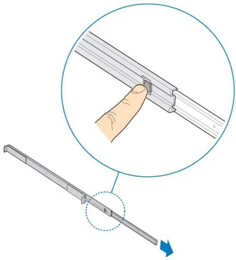
natural_image
Illustration showing a hand inserting a metal bracket into a rail track, with an arrow indicating direction (no text or symbols present)TP02006
Figure 107. Detaching Inner Rack Rail from Rack Rail Assembly
- Attach inner rack rails (one per side) to chassis with four 6-32 screws.
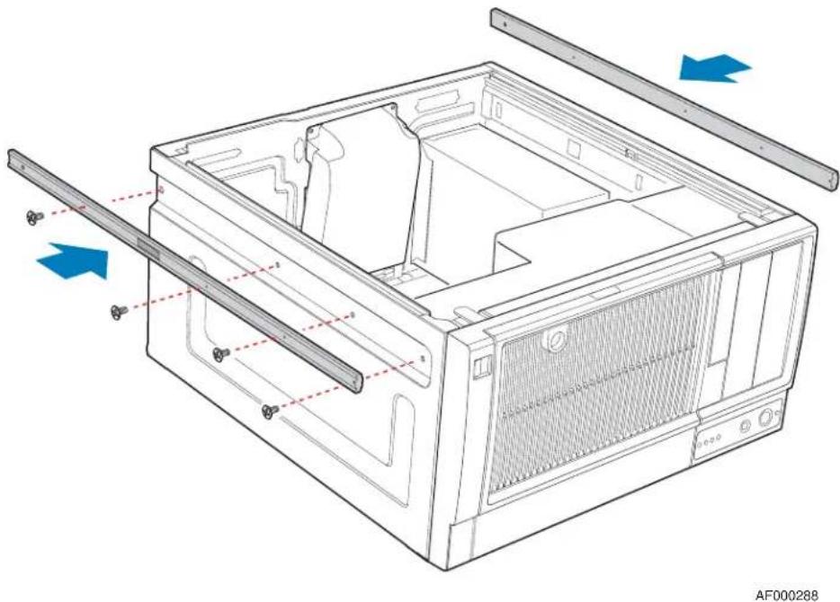
natural_image
Technical line drawing of a computer case with internal components and directional arrows indicating assembly (no text or symbols)Figure 108. Attaching Inner Rack Rails to Chassis
- Attach outer rack rails to rack uprights. Ensure that the screws (two per outer rack rail; see letter "A" in the following figure) pass through the rack upright (see letter "B"), and the outer rack rail (see letter "C").
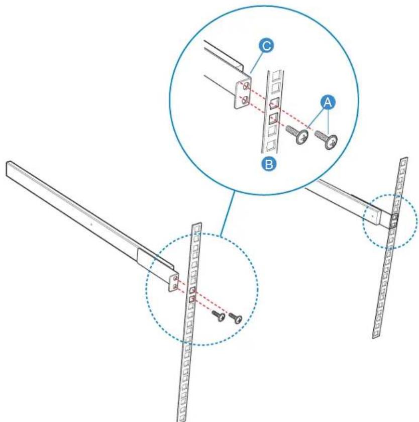
TP01056
Figure 109. Attaching Outer Rack Rails to Rack Uprights
- Install chassis into rack.
Warning: Safe handling and lifting of this system requires TWO people.
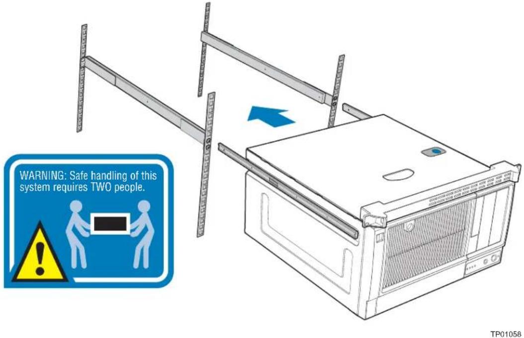
Figure 110. Installing Chassis into Rack
- Reconnect all peripheral devices and the AC power cable to the server. Power up the server.
Rack Mount Kit Install Instructions (optional)
5 Technical Reference
Cable Routing
When you add or remove components from your server chassis, make sure your cables are routed correctly before reinstalling the chassis cover. Use caution to make sure no cables or wires are pinched and that the airflow from the fans is not blocked.
Power Supply Specifications
The power supply specifications for your Intel ^® Entry Server Chassis SC5299-E will depend upon the configuration of chassis you purchased. Four power supply configurations are available:
- 550-W PFC fixed power supply (DP configuration)
- 650-W PFC redundant power supply (BRP configuration)
- 670-W PFC fixed power supply (WS configuration)
550-W Single Power Supply Input Voltages
• 100-127V at 50/60 Hz; 140 V rms max.
• 200-240V at 50/60 Hz; 264 V rms max.
550-W Single Power Supply Output Current
The following table lists the total amperage available from the power subsystem for each voltage. Ensure that your loads do not exceed the combined total wattage of 550 Watts.
Table 4. 550-W Power Supply Output Capability
| Voltage | Maximum Current |
| +3.3 V 24 A | |
| +5.0 V 24 A | |
| +5 V Standby 3 A | |
| +12.0 V1 40 A | |
| -12.0 V 0.5 A | |
| +12 V2 16 A |
670-W Single Power Supply Input Voltages
• 100-127V at 50/60 Hz; 12 A rms max.
• 200-240V at 50/60 Hz; 7 A rms max.
670-W Single Power Supply Output Voltages
The following table lists the total amperage available from the power subsystem for each voltage. Ensure that your loads do not exceed the combined total wattage of 670 Watts.
Table 5. 670-W Power Supply Output Capability
| Voltage | Maximum Current |
| +3.3 V 24 A | |
| +5.0 V 30 A | |
| +5 V Standby 3.0 A | |
| +12 V1 16 A | |
| +12 V2 16 A | |
| +12 V3 16 A | |
| +12 V4 16 A | |
| -12.0 V 0.5 A |
650-W Single Power Supply Input Voltages
• 100-127V at 50/60 Hz; 9.63 A rms max.
• 200-240V at 50/60 Hz; 4.82 A rms max.
650-W Single Power Supply Output Voltages
The following table lists the total amperage available from the power subsystem for each voltage. Ensure that your loads do not exceed the combined total wattage of 650 Watts.
Table 6. 650-W Power Supply Output Capability
| Voltage | Maximum Current |
| +3.3 V 24 A | |
| +5.0 V 30 A | |
| +5 V Standby 3.0 A | |
| -12.0 V 0.3 A | |
| 12 V1 16 A | |
| 12 V2 16 A | |
| 12 V3 16 A |
Table 6. 650-W Power Supply Output Capability
| Voltage | Maximum Current |
| 12 V4 16 A | |
| 12 V5 18 A |
System Environmental Specifications
Table 7. System Environmental Specifications
| Temperature | |
| Non-operating | -40 ° to 70 °C. |
| Operating | 10 ° to 35 °C; derated 0.5 °C for every 1000 ft (305 m) to a maximum of 10,000 ft. |
| Humidity | |
| Non-operating | 90% relative humidity (non-condensing) at 30 °C. |
| Shock | |
| Operating | 2.0 g, 11 msec, 1/2 sine |
| Packaged | Operational after an 18" free fall. |
| Acoustic noise DP, | BRP configurations - 5.5 BA LWA idle; 6.0 BA LWA typical operationWS configuration - 4.8 BA LWA idle; 5.5 BA LWA typical operation |
| Electrostatic discharge (ESD) | Tested to 15 kilovolts (kV); no component damage. |
Technical Reference
English
Server Safety Information
This document applies to Intel ^® server boards, Intel ^® server chassis (pedestal and rack-mount) and installed peripherals. To reduce the risk of bodily injury, electrical shock, fire, and equipment damage, read this document and observe all warnings and precautions in this guide before installing or maintaining your Intel ^® server product.
In the event of a conflict between the information in this document and information provided with the product or on the website for a particular product, the product documentation takes precedence.
Your server should be integrated and serviced only by technically qualified persons.
You must adhere to the guidelines in this guide and the assembly instructions in your server manuals to ensure and maintain compliance with existing product certifications and approvals. Use only the described, regulated components specified in this guide. Use of other products / components will void the UL Listing and other regulatory approvals of the product, and may result in noncompliance with product regulations in the region(s) in which the product is sold.
Safety Warnings and Cautions
To avoid personal injury or property damage, before you begin installing the product, read, observe, and adhere to all of the following safety instructions and information. The following safety symbols may be used throughout the documentation and may be marked on the product and / or the product packaging.
| CAUTION | Indicates the presence of a hazard that may cause minor personal injury or property damage if the CAUTION is ignored. | |
| WARNING | Indicates the presence of a hazard that may result in serious personal injury if the WARNING is ignored. | |
 | Indicates potential hazard if indicated information is ignored. | |
 | Indicates shock hazards that result in serious injury or death if safety instructions are not followed. | |
 | Indicates hot components or surfaces. | |
 | Indicates do not touch fan blades, may result in injury. | |
 | Indicates to unplug all AC power cord(s) to disconnect AC power | |
 | Please recycle battery | |
Intended Application Uses
This product was evaluated as Information Technology Equipment (ITE), which may be installed in offices, schools, computer rooms, and similar commercial type locations. The suitability of this product for other product categories and environments (such as medical, industrial, residential, alarm systems, and test equipment), other than an ITE application, may require further evaluation.
Site Selection
The system is designed to operate in a typical office environment. Choose a site that is:
- Clean, dry, and free of airborne particles (other than normal room dust).
- Well-ventilated and away from sources of heat including direct sunlight and radiators.
- Away from sources of vibration or physical shock.
- Isolated from strong electromagnetic fields produced by electrical devices.
- In regions that are susceptible to electrical storms, we recommend you plug your system into a surge suppresser and disconnect telecommunication lines to your modem during an electrical storm.
- Provided with a properly grounded wall outlet.
- Provided with sufficient space to access the power supply cord(s), because they serve as the product's main power disconnect.
Equipment Handling Practices
Reduce the risk of personal injury or equipment damage:
- Conform to local occupational health and safety requirements when moving and lifting equipment.
- Use mechanical assistance or other suitable assistance when moving and lifting equipment.
- To reduce the weight for easier handling, remove any easily detachable components.
Power and Electrical Warnings
Caution: The power button, indicated by the stand-by power marking, DOES NOT completely turn off the system AC power, 5V standby power is active whenever the system is plugged in. To remove power from system, you must unplug the AC power cord from the wall outlet. Your system may use more than one AC power cord. Make sure all AC power cords are
unplugged. Make sure the AC power cord(s) is/are unplugged before you open the chassis, or add or remove any non hot-plug components.
Do not attempt to modify or use an AC power cord if it is not the exact type required. A separate AC cord is required for each system power supply.
Some power supplies in Intel ^® servers use Neutral Pole Fusing. To avoid risk of shock use caution when working with power supplies that use Neutral Pole Fusing.
The power supply in this product contains no user-serviceable parts. Do not open the power supply. Hazardous voltage, current and energy levels are present inside the power supply. Return to manufacturer for servicing.
When replacing a hot-plug power supply, unplug the power cord to the power supply being replaced before removing it from the server.
To avoid risk of electric shock, turn off the server and disconnect the power cord, telecommunications systems, networks, and modems attached to the server before opening it.
Power Cord Warnings
If an AC power cord was not provided with your product, purchase one that is approved for use in your country.
Caution: To avoid electrical shock or fire, check the power cord(s) that will be used with the product as follows:
- Do not attempt to modify or use the AC power cord(s) if they are not the exact type required to fit into the grounded electrical outlets
- The power cord(s) must meet the following criteria:
- The power cord must have an electrical rating that is greater than that of the electrical current rating marked on the product.
- The power cord must have safety ground pin or contact that is suitable for the electrical outlet.
- The power supply cord(s) is/are the main disconnect device to AC power. The socket outlet(s) must be near the equipment and readily accessible for disconnection.
- The power supply cord(s) must be plugged into socket-outlet(s) that is /are provided with a suitable earth ground.
System Access Warnings
Caution: To avoid personal injury or property damage, the following safety instructions apply whenever accessing the inside of the product:
- Turn off all peripheral devices connected to this product.
- Turn off the system by pressing the power button to off.
-
Disconnect the AC power by unplugging all AC power cords from the system or wall outlet.
-
Disconnect all cables and telecommunication lines that are connected to the system.
- Retain all screws or other fasteners when removing access cover(s). Upon completion of accessing inside the product, refasten access cover with original screws or fasteners.
- Do not access the inside of the power supply. There are no serviceable parts in the power supply. Return to manufacturer for servicing.
- Power down the server and disconnect all power cords before adding or replacing any non hot-plug component.
- When replacing a hot-plug power supply, unplug the power cord to the power supply being replaced before removing the power supply from the server.
Caution: If the server has been running, any installed processor(s) and heat sink(s) may be hot. Unless you are adding or removing a hot-plug component, allow the system to cool before opening the covers. To avoid the possibility of coming into contact with hot component(s) during a hot-plug installation, be careful when removing or installing the hot-plug component(s).
Caution: To avoid injury do not contact moving fan blades. If your system is supplied with a guard over the fan, do not operate the system without the fan guard in place.
Rack Mount Warnings
The equipment rack must be anchored to an unmovable support to prevent it from tipping when a server or piece of equipment is extended from it. The equipment rack must be installed according to the rack manufacturer's instructions.
Install equipment in the rack from the bottom up, with the heaviest equipment at the bottom of the rack.
Extend only one piece of equipment from the rack at a time.
You are responsible for installing a main power disconnect for the entire rack unit. This main disconnect must be readily accessible, and it must be labeled as controlling power to the entire unit, not just to the server(s).
To avoid risk of potential electric shock, a proper safety ground must be implemented for the rack and each piece of equipment installed in it.
Electrostatic Discharge (ESD)
Caution: ESD can damage disk drives, boards, and other parts. We recommend that you perform all procedures at an ESD workstation. If one is not available, provide some ESD protection by wearing an antistatic wrist strap attached to chassis ground -- any unpainted metal surface -- on your server when handling parts.
Always handle boards carefully. They can be extremely sensitive to ESD. Hold boards only by their edges. After removing a board from its protective wrapper or from the server, place the board component side up on a grounded, static free surface. Use a
conductive foam pad if available but not the board wrapper. Do not slide board over any surface.
Other Hazards
Battery Replacement
Caution: There is the danger of explosion if the battery is incorrectly replaced. When replacing the battery, use only the battery recommended by the equipment manufacturer.
Dispose of batteries according to local ordinances and regulations.
Do not attempt to recharge a battery.
Do not attempt to disassemble, puncture, or otherwise damage a battery.
Cooling and Airflow
Caution: Carefully route cables as directed to minimize airflow blockage and cooling problems.
For proper cooling and airflow, operate the system only with the chassis covers installed. Operating the system without the covers in place can damage system parts. To install the covers:
- Check first to make sure you have not left loose tools or parts inside the system.
- Check that cables, add-in boards, and other components are properly installed.
- Attach the covers to the chassis according to the product instructions.
Laser Peripherals or Devices
Caution: To avoid risk of radiation exposure and/or personal injury:
- Do not open the enclosure of any laser peripheral or device
- Laser peripherals or devices have are not user serviceable
- Return to manufacturer for servicing
Deutsch
B Installation/Assembly Safety Instructions
English
 | The power supply in this product contains no user-serviceable parts. Refer servicing only to qualified personnel. |
 | Do not attempt to modify or use the supplied AC power cord if it is not the exact type required. A product with more than one power supply will have a separate AC power cord for each supply. |
 | The power button on the system does not turn off system AC power. To remove AC power from the system, you must unplug each AC power cord from the wall outlet or power supply.The power cord(s) is considered the disconnect device to the main (AC) power. The socket outlet that the system plugs into shall be installed near the equipment and shall be easily accessible. |
 | SAFETY STEPS: Whenever you remove the chassis covers to access the inside of the system, follow these steps:1. Turn off all peripheral devices connected to the system.2. Turn off the system by pressing the power button.3. Unplug all AC power cords from the system or from wall outlets.4. Label and disconnect all cables connected to I/O connectors or ports on the back of the system.5. Provide some electrostatic discharge (ESD) protection by wearing an antistatic wrist strap attached to chassis ground of the system-any unpainted metal surface-when handling components.6. Do not operate the system with the chassis covers removed. |
 | After you have completed the six SAFETY steps above, you can remove the system covers. To do this:1. Unlock and remove the padlock from the back of the system if a padlock has been installed.2. Remove and save all screws from the covers.3. Remove the cover(s). |
 | For proper cooling and airflow, always reinstall the chassis covers before turning on the system. Operating the system without the covers in place can damage system parts. To install the covers:1. Check first to make sure you have not left loose tools or parts inside the system.2. Check that cables, add-in boards, and other components are properly installed.3. Attach the covers to the chassis with the screws removed earlier, and tighten them firmly.4. Insert and lock the padlock to the system to prevent unauthorized access inside the system.5. Connect all external cables and the AC power cord(s) to the system. |
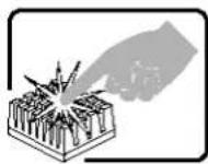 | A microprocessor and heat sink may be hot if the system has been running. Also, there may be sharp pins and edges on some board and chassis parts. Contact should be made with care. Consider wearing protective gloves. |
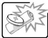 | Danger of explosion if the battery is incorrectly replaced. Replace only with the same or equivalent type recommended by the equipment manufacturer. Dispose of used batteries according to manufacturer's instructions. |
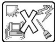 | The system is designed to operate in a typical office environment. Choose a site that is:Clean and free of airborne particles (other than normal room dust).Well ventilated and away from sources of heat including direct sunlight.Away from sources of vibration or physical shock.Isolated from strong electromagnetic fields produced by electrical devices.In regions that are susceptible to electrical storms, we recommend you plug your system into a surge suppresser and disconnect telecommunication lines to your modem during an electrical storm.Provided with a properly grounded wall outlet.Provided with sufficient space to access the power supply cord(s), because they serve as the product's main power disconnect. |
Deutsch
Installation/Assembly Safety Instructions
World Wide Web
http://support.intel.com/support/motherboards/server/chassis/sc5299-e/.
Telephone
All calls are billed US \$25.00 per incident, levied in local currency at the applicable credit card exchange rate plus applicable taxes. (Intel reserves the right to change the pricing for telephone support at any time without notice).
Before calling, fill out an “Intel® Server Issue Report Form”. A sample form is provided on the following pages. However, for the fastest service, please submit your form via the Internet.
For an updated support contact list, see http://www.intel.com/support/9089.htm/
U.S. and Canada
1-800-404-2284
Europe
Belgium ..... 02 714 3182
Denmark ... 38 487077
Finland ..... 9 693 79297
France..... 01 41 918529
Germany ... 069 9509 6099
Holland..... 020 487 4562
Italy...... 02 696 33276
Norway ..... 23 1620 50
Spain...... 91 377 8166
Sweden..... 08 445 1251
UK...... 870 6072439
In Asia-Pacific region
Australia.... 1800 649931
Cambodia.. 63 2 636 9797 (via Philippines)
China...... 800 820 1100 (toll-free)
8 621 33104691 (not toll-free)
Hong Kong 852 2 844 4456
India...... 0006517 2 68303634 (manual toll-free. You need an IDD-equipped telephone)
Indonesia... 803 65 7249
Korea...... 822 767 2595
Malaysia.... 1 800 80 1390
Myanmar... 63 2 636 9796 (via Philippines)
New Zealand 0800 444 365
Pakistan..... 632 63684 15 (IDD via Philippines)
Philippines 1 800 1 651 0117
Singapore .. 65 6213-1311
Taiwan..... 2 2545-1640
Thailand.... 1 800 631 0003
Vietnam ..... 632 6368416 (IDD via Philippines)
Japan
Domestic.... 0120 868686
Outside country 81 298 47 0800
Latin America
Argentina .. Contact AT&T USA at 0-800 222 1288. Once connected, dial 800 843 4481
Brazil...... 001-916 377 0180
Chile
Easter Island. ...... Contact AT&T USA at 800 800 311. Once connected, dial 800 843 4481
Mainland and Juan .. Contact AT&T USA at 800 225 288. Once connected, dial 800 843 4481
Colombia... Contact AT&T USA at 01 800 911 0010. Once connected, dial 800 843 4481
Costa Rica. Contact AT&T USA at 0 800 0 114 114. Once connected, dial 800 843 4481
Ecuador
(Andimate)....Contact AT&T USA at 1 999 119. Once connected, dial 800 843 4481
(Pacifictel) .....Contact AT&T USA at 1 800 225 528. Once connected, dial 800 843 4481
Guatemala. Contact AT&T USA at 99 99 190. Once connected, dial 800 843 4481
Mexico ..... Contact AT&T USA at 001 800 462 628 4240. Once connected, dial 800 843 4481
Miami ..... 1 800 621 8423
Panama.....Contact AT&T USA at 00 800 001 0109. Once connected, dial 800 843 4481
Paraguay ... 001 916 377 0114
Peru ...... 001 916 377 0114
Uruguay..... 001 916 377 0114
Venezuela... Contact AT&T USA at 0 800 2255 288. Once connected, dial 800 843 4481
Getting Help
Note: An on-line / automatic submission version of this form is available at http://support.intel.com/support/motherboards/server/chassis/sc5299-e/. For the fastest service, please submit your form via the Internet.
Date Submitted: ____
Company Name: ____
Contact Name: ____
Email Address: ____
Intel Server Product: ____
Priority (Critical, Hot, High, Low): ____
Brief Problem Description. Provide a brief description below. See the last page for space to include a detailed problem description.
Board / Chassis Information
Baseboard Revision - PBA#: ____
Baseboard Serial Number: ____
Chassis Model:
CPU1 Speed/Stepping/Spec: ____
CPU2 Speed/Stepping/Spec: ____
System BIOS Version: ____
DIMM1A MB and Vendor / part number: ____
DIMM1B MB and Vendor / part number: ____
DIMM2A MB and Vendor / part number: ____
DIMM2B MB and Vendor / part number: ____
DIMM3A MB and Vendor / part number: ____
DIMM3B MB and Vendor / part number: ____
DIMM4A MB and Vendor / part number: ____
DIMM4B MB and Vendor / part number: ____
Operating System Information
Operating System: ____
Version: ____
Service Pack: ____
Add-in Card, Peripheral, Video, NIC
Check each box below as applicable, and provide the requested information.
Peripheral Card or Peripheral Description Driver Revision IRQ # I/O Base Address NIC
| X Peripheral Description | Driver Revision | IRQ | I/O Base Address | FW Revision | ||
| Low-profile Riser | ||||||
| PCI Slot 1 | ||||||
| PCI Slot 2 | ||||||
| PCI Slot 3 | ||||||
| Full-height Riser | ||||||
| PCI Slot 1 | ||||||
| PCI Slot 2 | ||||||
| PCI Slot 3 | ||||||
| Video | ||||||
| On-board Video | ||||||
| Add-in Video | ||||||
| NIC | ||||||
| On-Board NIC1 | ||||||
| X Peripheral Description | Driver Revision | IRQ | I/O Base Address | FW Revision | |
| On-board NIC2 |
Hard Drive Information
| X | Drive Type (SCSI, SATA, etc) | Make/Model | Hot-swap or Fixed | IRQ | FW Revision |
Management Information
On-board Platform Instrumentation only
Intel® Management Module - Professional Edition
Intel® Management Module - Advanced Edition ____
Control Panel Information
Standard Control Panel ____
Intel ^® Local Control Panel
Complete Problem Description
In the space below, provide a complete description of the steps used to reproduce the problem or a complete description of where the problem can be found. Please also include any details on troubleshooting already done.
Limited Warranty for Intel® Chassis Subassembly Products
Intel warrants that the Products (defined herein as the Intel® chassis subassembly and all of its various components and software delivered with or as part of the Products) to be delivered hereunder, if properly used and installed, will be free from defects in material and workmanship and will substantially conform to Intel's publicly available specifications for a period of three (3) years after the date the Product was purchased from an Intel authorized distributor. Software of any kind delivered with or as part of products is expressly provided "as is" unless specifically provided for otherwise in any software license accompanying the software.
If any Product furnished by Intel which is the subject of this Limited Warranty fails during the warranty period for reasons covered by this Limited Warranty, Intel, at its option, will:
- REPAIR the Product by means of hardware and/or software; OR
- REPLACE the Product with another Product; OR
- REFUND the then-current value of the Product if Intel is unable to repair or replace the Product.
If such Product is defective, transportation charges for the return of Product to buyer within the USA will be paid by Intel. For all other locations, the warranty excludes all costs of shipping, customs clearance, and other related charges. Intel will have a reasonable time to make repairs or to replace Product or to refund the then-current value of the Product.
In no event will Intel be liable for any other costs associated with the replacement or repair of Product, including labor, installation or other costs incurred by buyer and in particular, any costs relating to the removal or replacement of any product soldered or otherwise permanently affixed to any printed circuit board.
This Limited Warranty, and any implied warranties that may exist under state law, apply only to the original purchaser of the Product.
Extent of Limited Warranty
Intel does not warrant that Products to be delivered hereunder, whether delivered standalone or integrated with other Products, including without limitation semiconductor components, will be free from design defects or errors known as "errata." Current characterized errata are available upon request.
This Limited Warranty does not cover damages due to external causes, including accident, problems with electrical power, usage not in accordance with product instructions, misuse, neglect, alteration, repair, improper installation, or improper testing.
Warranty Limitations and Exclusions
These warranties replace all other warranties, expressed or implied including, but not limited to, the implied warranties of merchantability and fitness for a particular purpose. Intel makes no expressed warranties beyond those stated here. Intel disclaims all other warranties, expressed or implied including, without limitation, implied warranties of merchantability and fitness for a particular purpose. Some jurisdictions do not allow the exclusion of implied warranties, so this limitation may not apply.
All expressed and implied warranties are limited in duration to the limited warranty period. No warranties apply after that period. Some jurisdictions do not allow limitations on how long an implied warranty lasts, so this limitation may not apply to you.
Limitations of Liability
Intel's responsibility under this, or any other warranty, implied or expressed, is limited to repair, replacement, or refund, as set forth above. These remedies are the sole and exclusive remedies for any breach of warranty. Intel is not responsible for direct, special, incidental, or consequential damages resulting from any breach of warranty under another legal theory including, but not limited to, lost profits, downtime, goodwill, damage to or replacement of equipment and property, and any costs of recovering, reprogramming, or reproducing any program or data stored in or used with a system containing this product. Some jurisdictions do not allow the exclusion or limitation of incidental or consequential damages, so the above limitations or exclusions may not apply to you.
This limited warranty gives you specific legal rights, and you may also have other rights that vary from jurisdiction to jurisdiction.
Any and all disputes arising under or related to this Limited Warranty shall be adjudicated in the following forums and governed by the following laws: for the United States of America, Canada, North America, and South America, the forum shall be Santa Clara, California, USA, and the applicable law shall be that of the State of California, USA; for the Asia Pacific region, the forum shall be Singapore and the applicable law shall be that of Singapore; for Europe and the rest of the world, the forum shall be London and the applicable law shall be that of the United Kingdom.
In the event of any conflict between the English language version and any other translated version(s) of this Limited Warranty, the English language version shall control.
How to Obtain Warranty Service
To obtain warranty service for this Product, you may contact Intel or your authorized distributor.
- North America and Latin America To obtain warranty repair for the product, please go to the following Web site to obtain instructions: http://support.intel.com/support/motherboards/draform.htm
- In Europe and in Asia Contact your original authorized distributor for warranty service.
Any replacement Product is warranted under this written warranty and is subject to the same limitations and exclusions for the remainder of the original warranty period.
Telephone Support
If you cannot find the information you need on Intel's World Wide Web site (http://www.intel.com/), call your local distributor or an Intel Customer Support representative. See “Getting Help” for telephone numbers.
Returning a Defective Product
Before returning any product, call your authorized dealer/distribution authority.
Warranty
F Regulatory and Compliance Information
Product Regulatory Compliance
Warning: To ensure regulatory compliance, you must adhere to the assembly instructions in this guide to ensure and maintain compliance with existing product certifications and approvals. Use only the described, regulated components specified in this guide. Use of other products/components will void the UL listing and other regulatory approvals of the product and will most likely result in noncompliance with product regulations in the region(s) in which the product is sold.
To help ensure EMC compliance with your local regional rules and regulations, before computer integration, make sure that the chassis, power supply, and other modules have passed EMC testing using a server board with a microprocessor from the same family (or higher) and operating at the same (or higher) speed as the microprocessor used on this server board. The final configuration of your end system product may require additional EMC compliance testing. For more information, please contact your local Intel representative.
This is an FCC Class A device. Integration of it into a Class B chassis does not result in a Class B device.
Product Safety Compliance
This server chassis product, when correctly integrated per this guide, complies with the following safety and electromagnetic compatibility (EMC) regulations.
Intended Application
This product was evaluated as Information Technology Equipment (ITE), which may be installed in offices, schools, computer rooms, and similar commercial type locations. The suitability of this product for other product categories and environments (such as: medical, industrial, telecommunications, NEBS, residential, alarm systems, test equipment, etc.), other than an ITE application, may require further evaluation.
Product Safety Compliance
The server chassis complies with the following product safety requirements:
• UL60950 - CSA 60950 (USA / Canada)
• EN60950 (Europe)
• IEC60950 (International)
• CB Certificate & Report, IEC60950 (report to include all country national deviations)
• GS License (Germany)
• GOST R 50377-92 - License (Russia)
• Belarus License (Belarus)
• Ukraine License (Ukraine)
• CE - Low Voltage Directive 73/23/EEE (Europe)
• IRAM Certification (Argentina)
• GB4943- CNCA Certification (China)
Product EMC Compliance - Class A Compliance
This server chassis has been tested and verified to comply with the following electromagnetic compatibility (EMC) regulations when installed in a compatible Intel® host system. For information on compatible host system(s) refer to Intel's Server Builder Web site or contact your local Intel representative.
• FCC /ICES-003 - Emissions (USA/Canada) Verification
• CISPR 22 - Emissions (International)
• EN55022 - Emissions (Europe)
• EN55024 - Immunity (Europe)
• EN61000-3-2 - Harmonics (Europe)
• EN61000-3-3 - Voltage Flicker (Europe)
• CE - EMC Directive 89/336/EEC (Europe)
• VCCI Emissions (Japan)
• AS/NZS 3548 Emissions (Australia / New Zealand)
• BSMI CNS13438 Emissions (Taiwan)
• GOST R 29216-91 Emissions (Russia)
• GOST R 50628-95 Immunity (Russia)
• Belarus License (Belarus)
• Ukraine License (Ukraine)
• RRL MIC Notice No. 1997-41 (EMC) & 1997-42 (EMI) (Korea)
• GB 9254 - CNCA Certification (China)
• GB 17625 - (Harmonics) CNCA Certification (China)
Certifications / Registrations / Declarations
• UL Certification (US/Canada)
• CE Declaration of Conformity (CENELEC Europe)
• FCC/ICES-003 Class A Attestation (USA/Canada)
• VCCI Certification (Japan)
• C-Tick Declaration of Conformity (Australia)
• MED Declaration of Conformity (New Zealand)
• BSMI Certification (Taiwan)
• GOST R Certification / License (Russia)
• Belarus Certification / License (Belarus)
• RRL Certification (Korea)
• IRAM Certification (Argentina)
• CNCA Certification (China)
• Ecology Declaration (International)
Product Regulatory Compliance Markings
This Intel ^® server chassis product bears the following regulatory marks.
Table 8. Product Regulatory Compliance Markings
| Regulatory Compliance | Region Marking | |
| cULus Listing Marks USA/Canada |  | |
| GS Mark Germany |   | |
| CE Mark Europe |  | |
| FCC Marking (Class A) USA | This device complies with Part 15 of the FCC Rules. Operation of this device is subject to the following two conditions:(1) This device may not cause harmful interference, and(2) This device must accept any interference received, including interference that may cause undesired operation. Manufactured by Intel Corporation | |
| EMC Marking (Class A) Canada | CANADA ICES-003 CLASS A CANADA NMB-003 CLASSE A | |
| VCCI Marking (Class A) Japan | この装置は、クラス A 情報技術装置です。この装置を家庭環境で使用すると電波妨害を引き起こすことがあります。この場合には使用者が適切な対策を講ずるよう要求されることがあります。VCCI-A | |
Table 8. Product Regulatory Compliance Markings
| Regulatory Compliance | Region Marking | |
| BSMI Certification Number & Class A Warning | Taiwan |  警告使用者:這是甲類的資訊產品,在居住的環境中使用時,可能會造成射頻干擾,在這種情況下,使用者會被要求採取某些適當的對策 警告使用者:這是甲類的資訊產品,在居住的環境中使用時,可能會造成射頻干擾,在這種情況下,使用者會被要求採取某些適當的對策 |
| GOST R Marking Russia |  | |
| RRL MIC Mark Korea |  | |
| China Compulsory Certification Mark | China |  |
Electromagnetic Compatibility Notices
FCC Verification Statement (USA)
This device complies with Part 15 of the FCC Rules. Operation is subject to the following two conditions: (1) this device may not cause harmful interference, and (2) this device must accept any interference received, including interference that may cause undesired operation.
For questions related to the EMC performance of this product, contact:
Intel Corporation
5200 N.E. Elam Young Parkway
Hillsboro, OR 97124-6497
1-800-628-8686
This equipment has been tested and found to comply with the limits for a Class A digital device, pursuant to Part 15 of the FCC Rules. These limits are designed to provide reasonable protection against harmful interference in a residential installation. This equipment generates, uses, and can radiate radio frequency energy and, if not installed and used in accordance with the instructions, may cause harmful interference to radio communications. However, there is no guarantee that interference will not occur in a particular installation. If this equipment does cause harmful interference to radio or television reception, which can be determined by turning the equipment off and on, the user is encouraged to try to correct the interference by one or more of the following measures:
• Reorient or relocate the receiving antenna.
- Increase the separation between the equipment and the receiver.
- Connect the equipment to an outlet on a circuit other than the one to which the receiver is connected.
- Consult the dealer or an experienced radio/TV technician for help.
Any changes or modifications not expressly approved by the grantee of this device could void the user's authority to operate the equipment. The customer is responsible for ensuring compliance of the modified product.
Only peripherals (computer input/output devices, terminals, printers, etc.) that comply with FCC Class A or B limits may be attached to this computer product. Operation with noncompliant peripherals is likely to result in interference to radio and TV reception.
All cables used to connect to peripherals must be shielded and grounded. Operation with cables, connected to peripherals, that are not shielded and grounded may result in interference to radio and TV reception.
Industry Canada (ICES-003)
English translation of the notice above:
This digital apparatus does not exceed the Class A limits for radio noise emissions from digital apparatus set out in the interference-causing equipment standard entitled: "Digital Apparatus," ICES-003 of the Canadian Department of Communications.
Europe (CE Declaration of Conformity)
This product has been tested in accordance to, and complies with the Low Voltage Directive (73/23/EEC) and EMC Directive (89/336/EEC). The product has been marked with the CE Mark to illustrate its compliance.
VCCI (Japan)
English translation of the preceding notice:
This is a Class A product based on the standard of the Voluntary Control Council for Interference (VCCI) from Information Technology Equipment. If this is used near a radio or television receiver in a domestic environment, it may cause radio interference. Install and use the equipment according to the instruction manual.
BSMI (Taiwan)
警告使用者:
The BSMI Certification Marking and EMC warning is located on the outside rear area of the product.
Korean Compliance (RRL)
Following is the RRL certification information for Korea.

English translation of the notice above:
- Type of Equipment (Model Name): On License and Product
- Certification No.: On RRL certificate. Obtain certificate from local Intel representative
- Name of Certification Recipient: Intel Corporation
- Date of Manufacturer: Refer to date code on product
- Manufacturer/Nation: Intel Corporation/Refer to country of origin marked on product
Regulated Specified Components
To maintain the UL listing and compliance to other regulatory certifications and/or declarations, the following regulated components must be used and conditions adhered to. Interchanging or use of other components will void the UL listing and other product certifications and approvals.
Updated product information for configurations can be found on the Intel Server Builder Web site at the following URL:
http://channel.intel.com/go/serverbuilder
If you do not have access to Intel's Web address, please contact your local Intel representative.
- Server Chassis: (base chassis is provided with power supply and fans) - UL listed.
- Server board: you must use an Intel server board - UL recognized.
- Add-in boards: must have a printed wiring board flammability rating of minimum UL94V-1. Add-in boards containing external power connectors and/or lithium batteries must be UL recognized or UL listed. Any add-in board containing modem telecommunication circuitry must be UL listed. In addition, the modem must have the appropriate telecommunications, safety, and EMC approvals for the region in which it is sold.
- Peripheral Storage Devices: must be a UL recognized or UL listed accessory and TUV or VDE licensed. Maximum power rating of any one device is 19 watts. Total server configuration is not to exceed the maximum loading conditions of the power supply.
Restriction of Hazardous Substances (RoHS) Compliance
Intel has a system in place to restrict the use of banned substances in accordance with the European Directive 2002/95/EC. Compliance is based on declaration that materials banned in the RoHS Directive are either (1) below all applicable substance threshold limits or (2) an approved/pending RoHS exemption applies.
Note: RoHS implementing details are not fully defined and may change.
Threshold limits and banned substances are noted as follows:
• Quantity limit of 0.1% by mass (1000 PPM) for:
— L e a d
— Mercury
— Hexavalent chromium
— Polybrominated biphenyls diphenyl ethers (PBDE)
• Quantity limit of 0.01% by mass (100 PPM) for:
— C a d m i u m
End of Life / Product Recycling
Product recycling and end-of-life take back systems and requirements vary from country to country. Contact the retailer or distributor of this product for information on product recycling and / or take back.
Regulatory and Compliance Information


- Intel® Entry Server Chassis SC5299-E DP/WS/BRP User Guide
- Disclaimer
- Important Safety Instructions
- About this Manual
- Manual Organization
- Product Contents, Order Options, and Accessories
- Additional Information and Software
- Contents
- Safety Information ....iii
- Server Chassis Features .... 1
- Hardware Installations and Upgrades 11
- Hot Swap Drive Cage Upgrade Install Instructions (optional) 55
- Rack Mount Kit Install Instructions (optional) 75
- Technical Reference 87
- Safety Information 91
- Regulatory and Compliance Information ....143
- List of Figures
- List of Tables
- Server Chassis Features
- Component Identification
- Front View Components
- Internal Components
- Back Panel Components
- Front Panel
- Peripheral Devices
- Hard Disk Drives
- Front Bezel Assembly
- Rack-Mounted Systems
- Mechanical Locks
- Accessories and Order Codes
- Hardware Installations and Upgrades
- Before You Begin
- Tools and Supplies Needed
- System References
- Removing and Installing the Left Side Cover
- Removing the Left Side Cover
- Installing the Left Side Cover
- Removing and Installing the Front Bezel Assembly
- Removing the Front Bezel Assembly
- Installing the Front Bezel Assembly
- Removing and Installing the Processor Air Duct
- Removing the Processor Air Duct
- Installing the Processor Air Duct
- Installing or Removing a Server Board
- Installing and Removing a Fixed Hard Drive
- Installing a Fixed Hard Drive
- Removing a Fixed Hard Drive
- Installing or Removing a DVD-ROM or CD-ROM Drive
- Installing a DVD-ROM or CD-ROM Drive
- Removing a CD-ROM or DVD-ROM Drive
- Installing the Removing PCI Add-in Boards
- Installing PCI Add-in Boards
- Removing PCI Add-in Boards
- Replacing the Front Panel Board
- Replacing a System Fan
- Replacing a Fixed Power Supply
- Installing an Additional Hot Swap Power Supply Module (BRP configuration only)
- Replacing a Hot Swap Power Supply (BRP configuration only)
- Replacing a Hot Swap Power Supply Cage (BRP configuration only)
- Installing Feet for a Pedestal-configured Chassis
- Hot Swap Drive Cage Upgrade Install Instructions (optional)
- Kits Required
- Installing a Hot Swap Hard Drive Cage with a SAS/SATA or SCSI Backplane
- c. If you are installing a SAS/SATA hot swap backplane without expander
- Installing a Hot Swap Hard Drive
- Removing a Hot-swap Hard Drive
- Rack Mount Kit Install Instructions (optional)
- Setting up a Rack-configured Chassis
- Technical Reference
- Cable Routing
- Power Supply Specifications
- 550-W Single Power Supply Input Voltages
- 550-W Single Power Supply Output Current
- 670-W Single Power Supply Input Voltages
- 670-W Single Power Supply Output Voltages
- 650-W Single Power Supply Input Voltages
- 650-W Single Power Supply Output Voltages
- System Environmental Specifications
- English
- Server Safety Information
- Safety Warnings and Cautions
- Intended Application Uses
- Site Selection
- Equipment Handling Practices
- Power and Electrical Warnings
- Power Cord Warnings
- System Access Warnings
- Rack Mount Warnings
- Electrostatic Discharge (ESD)
- Other Hazards
- Battery Replacement
- Cooling and Airflow
- Laser Peripherals or Devices
- Deutsch
- B Installation/Assembly Safety Instructions
- World Wide Web
- Telephone
- U.S. and Canada
- Europe
- In Asia-Pacific region
- Japan
- Latin America
- Ecuador
- Board / Chassis Information
- Operating System Information
- Add-in Card, Peripheral, Video, NIC
- Management Information
- Control Panel Information
- Complete Problem Description
- Limited Warranty for Intel® Chassis Subassembly Products
- Extent of Limited Warranty
- Warranty Limitations and Exclusions
- Limitations of Liability
- How to Obtain Warranty Service
- Telephone Support
- Returning a Defective Product
- F Regulatory and Compliance Information
- Product Regulatory Compliance
- Product Safety Compliance
- Intended Application
- Product EMC Compliance - Class A Compliance
- Certifications / Registrations / Declarations
- Product Regulatory Compliance Markings
- Electromagnetic Compatibility Notices
- FCC Verification Statement (USA)
- Industry Canada (ICES-003)
- Europe (CE Declaration of Conformity)
- VCCI (Japan)
- BSMI (Taiwan)
- 警告使用者:
- Korean Compliance (RRL)
- Regulated Specified Components
- Restriction of Hazardous Substances (RoHS) Compliance
- End of Life / Product Recycling
Brand : INTEL
Model : SC5299DP
Category : Uncategorized