AXXRMFBU2 - Uncategorized INTEL - Free user manual and instructions
Find the device manual for free AXXRMFBU2 INTEL in PDF.

| Product Type | RAID Controller Module |
| Model | AXXRMFBU2 |
| Form Factor | Low Profile MD2 |
| Interface | PCI Express 3.0 x8 |
| Supported RAID Levels | 0, 1, 5, 6, 10, 50, 60 |
| Cache Memory | 1 GB DDR3 |
| Ports | 2 x Mini-SAS HD (SFF-8643) |
| Maximum Drives Supported | Up to 32 SAS/SATA drives |
| Data Transfer Rate | 12 Gb/s per port |
| Operating Temperature | 0°C to 55°C |
| Storage Temperature | -40°C to 70°C |
| Dimensions (W x H x D) | 6.6 x 2.7 x 0.5 in (168 x 68 x 13 mm) |
| Weight | 0.5 lb (227 g) |
| Power Consumption | 15 W typical |
| Compatible Operating Systems | Windows, Linux, VMware |
| Management Software | Intel RAID Web Console, StorCLI |
| Security Features | Secure Erase, TCG Enterprise SSC |
| Warranty | 3 years limited |
Frequently Asked Questions - AXXRMFBU2 INTEL
User questions about AXXRMFBU2 INTEL
0 question about this device. Answer the ones you know or ask your own.
Ask a new question about this device
Download the instructions for your Uncategorized in PDF format for free! Find your manual AXXRMFBU2 - INTEL and take your electronic device back in hand. On this page are published all the documents necessary for the use of your device. AXXRMFBU2 by INTEL.
USER MANUAL AXXRMFBU2 INTEL
Intel® RAID Maintenance Free Backup Unit AXXRMFBU2 User's Guide
A Guide for Technically Qualified Assemblers of Intel ^® identified Subassemblies/Products
Intel Order Number: G49043-004

Disclaimer
Information in this document is provided in connection with Intel products. No license, express or implied, by estoppel or otherwise, to any intellectual property rights is granted by this document. Except as provided in Intel's Terms and Conditions of Sale for such products, Intel assumes no liability whatsoever, and Intel disclaims any express or implied warranty, relating to sale and/or use of Intel products including liability or warranties relating to fitness for a particular purpose, merchantability, or infringement of any patent, copyright or other intellectual property right. Intel products are not designed, intended or authorized for use in any medical, life saving, or life sustaining applications or for any other application in which the failure of the Intel product could create a situation where personal injury or death may occur. Intel may make changes to specifications and product descriptions at any time, without notice.
Intel server boards contain a number of high-density VLSI and power delivery components that need adequate airflow for cooling. Intel's own chassis are designed and tested to meet the intended thermal requirements of these components when the fully integrated system is used together. It is the responsibility of the system integrator that chooses not to use Intel developed server building blocks to consult vendor datasheets and operating parameters to determine the amount of airflow required for their specific application and environmental conditions. Intel Corporation cannot be held responsible if components fail or the server board does not operate correctly when used outside any of their published operating or non-operating limits.
Intel, Intel Pentium, and Intel Xeon are trademarks or registered trademarks of Intel Corporation or its subsidiaries in the United States and other countries.
* Other names and brands may be claimed as the property of others.
Copyright © 2013 Intel Corporation. All Rights Reserved.
Copyright © 2007 - 2013 LSI* Corporation. All Rights Reserved.
Intel warranties that this product will perform to its published specifications. However, all computer systems are inherently subject to unpredictable system behavior under various environmental and other conditions.
This product is not intended to be the sole source for any critical data and the user must maintain a verified backup. Failure to do so or to comply with other user notices in the product user guide and specification documents may result in loss of or access to data.
Important Safety Instructions
Read all caution and safety statements in this document before performing any of the instructions. See also Intel ^® Server Boards and Server Chassis Safety Information on the Intel ^® Server Deployment Toolkit 3.0 CD and/or at http://www.intel.com/support/motherboards/server/sb/cs-010770.htm.
Heed safety instructions: Before working with your server product, whether you are using this guide or any other resource as a reference, pay close attention to the safety instructions. You must adhere to the assembly instructions in this guide to ensure and maintain compliance with existing product certifications and approvals. Use only the described, regulated components specified in this guide. Use of other products/components will void the UL listing and other regulatory approvals of the product and will most likely result in noncompliance with product regulations in the region(s) in which the product is sold.
System power on/off: The power button DOES NOT turn off the system AC power. To remove power from the system, you must unplug the AC power cord from the wall outlet. Make sure the AC power cord is unplugged before you open the chassis, add, or remove any components.
Hazardous conditions, devices and cables: Hazardous electrical conditions may be present on power, telephone, and communication cables. Turn off the server and disconnect the power cord, telecommunications systems, networks, and modems attached to the server before opening it. Otherwise, personal injury or equipment damage can result.
Electrostatic discharge (ESD) and ESD protection: ESD can damage disk drives, boards, and other parts. We recommend that you perform all procedures in this chapter only at an ESD workstation. If one is not available, provide some ESD protection by wearing an antistatic wrist strap attached to chassis ground—any unpainted metal surface—on your server when handling parts.
ESD and handling boards: Always handle boards carefully. They can be extremely sensitive to ESD. Hold boards only by their edges. After removing a board from its protective wrapper or from the server, place the board component side up on a grounded, static free surface. Use a conductive foam pad if available but not the board wrapper. Do not slide board over any surface.
Installing or removing jumpers: A jumper is a small plastic encased conductor that slips over two jumper pins. Some jumpers have a small tab on top that you can grip with your fingertips or with a pair of fine needle nosed pliers. If your jumpers do not have such a tab, take care when using needle nosed pliers to remove or install a jumper; grip the narrow sides of the jumper with the pliers, never the wide sides. Gripping the wide sides can damage the contacts inside the jumper, causing intermittent problems with the function controlled by that jumper. Take care to grip with, but not squeeze, the pliers or other tool you use to remove a jumper, or you may bend or break the pins on the board.
Table of Contents
1 About the Intel ^® RAID Maintenance Free Backup Unit AXXRMFBU2 ......1
2 Installing the Hardware....2
Remote Connecting Cables....2
Important Pre-installation Considerations....3
Installing the Intel ^® RAID Maintenance Free Backup Unit AXXRMFBU2....3
Removing the RAID Module ....3
Installing the Intel ^® RAID Maintenance Free Backup Unit AXXRMFBU2....3
Connecting the Plastic RMFBU2 Holder to the Chassis....6
Attaching the Connecting Cable to the Server System....6
Installing the Intel ^® Integrated RAID Module in the Server System ....6
3 Monitoring RAID Maintenance Free Backup Unit 9
Monitoring the SuperCap with the Intel ^® RAID BIOS Configuration Utility....9
Using Intel ^® RAID Web Console 2....10
4 RAID Maintenance Free Backup Unit Specifications.... 11
MegaRAID CacheVault™ Technology....11
5 Regulatory and Compliance Information.... 12
Product Regulatory Compliance....12
Product Safety Compliance 12
Product EMC Compliance – Class A Compliance....12
Certifications/Registrations/Declarations 13
Product Regulatory Compliance Markings....13
Electromagnetic Compatibility Notices ....14
FCC (USA) 14
Industry Canada (ICES-003)....14
Europe (CE Declaration of Conformity)....15
Taiwan Declaration of Conformity (BSMI)....15
Korean Compliance (RRL)....15
6 Intel ^® Server Issue Report Form 18
List of Figures
Figure 1. Top View of the Intel ^® RAID Maintenance Free Backup Unit AXXRMFBU2 ......2
Figure 2. Connecting AXXRMFBU2 to the RAID Module ....4
Figure 3. Connect the cable ....5
Figure 5. Connecting the Plastic RMFBU2 Holder to the Chassis ....6
Figure 6. Seating the RAID Module....7
Figure 7. Tie Together the Cables with the Strap Tie ....7
Figure 8. Installing the Barrel Standoff ....8
Figure 9. Installing the Intel ^® Integrated RAID Module....8
Figure 10. Monitoring the RMFBU2 with Intel ^® RAID BIOS Console ......9
Figure 11. RMFBU2 Information in Intel® RAID Web Console 2....10
List of Tables
Table 1. Cable Compatibility ....2
Table 2. RMFBU2 Specifications .....11
Table 3. Product Certification Markings....13
1 About the Intel ^® RAID Maintenance Free Backup Unit AXXRMFBU2
Intel ^® Integrated RAID (Redundant Array of Inexpensive Disks) Modules provide reliability, high performance, and fault-tolerant disk subsystem management. A complete fault-tolerant strategy requires protection of all data, including the unwritten cached data in the RAM cache. If power is lost, the data in the RAM cache is lost. To avoid data loss, a RAID Maintenance Free Backup Unit (RMFBU) can be added to store unwritten cached data from the RAID RAM during an AC power outage or if the AC power cord is removed.
A RAID Maintenance Free Backup Unit protects the integrity of the cached data on Intel ^® Integrated RAID Modules by offloading data stored in the RAM cache to the NAND flash if there is a complete AC power failure or a brief power outage. The Intel ^® RAID Maintenance Free Backup Unit provides an alternative to use an uninterruptible power supply (UPS) or it can act as a second level of fault tolerance when used with a UPS. Furthermore, it eliminates the need for lithium ion (Li-ion) batteries traditionally used to protect DRAM cache memory on PCI RAID controllers. Therefore this is a greener and lower total cost cache protection solution.
The cache memory available on Intel® Integrated RAID Modules can improve the overall system performance. Writing data to the controller's cache memory is much faster than writing it to a storage device. Write operations appear to complete very quickly at the software application level. The Intel® Integrated RAID Module writes the cached data to the storage device when system activity is low or when the cache is getting full. The risk of using write-back cache is that the cached data can be lost if the AC power fails before it is written to the storage device. This risk factor is eliminated when the Intel® Integrated RAID Module has a RMFBU installed.
The Intel ^® RAID Maintenance Free Backup Unit AXXRMFBU2 consists of Cache Offload Module and SuperCap2. It monitors the voltage level of the DRAM modules of the Intel ^® Integrated RAID Module. If the voltage drops below a predefined level, the RMFBU offloads the data from the RAID RAM to the NAND flash of RMFBU2 Cache-offload Module and SuperCap2 provides sufficient power to complete the data transferring. When the voltage level returns to an acceptable level, the RAID RAM is recovered from flash, and all pending writes to storage devices are completed without losing any data.
The Intel ^® RAID Maintenance Free Backup Unit AXXRMFBU2 has a built-in functionality to charge the SuperCap2 automatically and to communicate entire unit status information such as voltage, temperature, and current to the host server system.
The Intel ^® RAID Maintenance Free Backup Unit AXXRMFBU2 is a smart backup module and uses MegaRAID CacheVault ^™ Technology. It is compatible with a backup auxiliary power source. The SuperCap2 is charged automatically.
2 Installing the Hardware
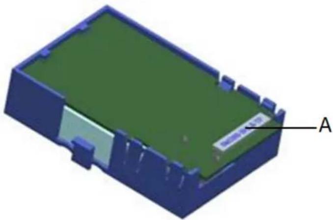
The Intel ^® RAID Maintenance Free Backup Unit AXXRMFBU2 pack attaches to the RAID modules remotely. Figure 1 displays the top view of the Intel ^® RAID Maintenance Free Backup Unit AXXRMFBU2. The 26-pin connector (see letter A for the location of this connector) is used to remotely connect to an Intel ^® Integrated RAID module using the supplied cable.
natural_image
3D model of a rectangular electronic device with green top and blue casing, labeled point A (no text or symbols on the object itself)Figure 1. Top View of the Intel® RAID Maintenance Free Backup Unit AXXRMFBU2
Remote Connecting Cables
Two 26-pin to 30-pin RMFBU2 Cache-offload Module cables (20-inch and 40-inch) are provided in the AXXRMFBU2 kit to remotely connect the Intel ^® RAID Maintenance Free Backup Unit AXXRMFBU2 to the Intel ^® Integrated RAID Module.
Table 1. Cable Compatibility
| Intel ^ RAID Controller or Server System | 20-inch Cable | 40-inch Cable |
| Intel ^ Integrated RAID Module RMS25PB080 | X | X |
| Intel ^ Integrated RAID Module RMS25PB040 | X | X |
| Intel ^ Integrated RAID Module RMT3PB080 | X | X |
| Intel ^ Integrated RAID Module RMS25CB080 | X | X |
| Intel ^ Integrated RAID Module RMS25CB040 | X | X |
| Intel ^ Integrated RAID Module RMT3CB080 | X | X |
| Intel ^ pedestal chassis | X | |
| Intel ^ rack mount chassis | X |
Important Pre-installation Considerations
Warning: Make sure that you are grounded and/or use a ground strap before touching the RAID module or the Intel ^® RAID Maintenance Free Backup Unit AXXRMFBU2. Perform all installation work at and ESD-safe workstation. Use an ESD-safe Phillips* screwdriver set to a maximum torque of 2.25 inch-pounds, and be sure the screwdriver is centered in the screw to avoid damaging the screw head. If you exceed the maximum torque specification, you may damage the board, connectors, or screws, and you will void the warranty of the board.
Installing the Intel ^® RAID Maintenance Free Backup Unit AXXRMFBU2
Warning: After the Intel ^® RAID Maintenance Free Backup Unit AXXRMFBU2 is installed, do not disconnect it from the Intel ^® Integrated RAID Module RMS25PB080, RMS25PB040, RMT3PB080, RMS25CB080, RMS25CB040, or RMT3CB080 when system has an unclean shutdown (that is, AC lost during operating system is running). Doing so will cause AXXRMFBU2 unrecoverable failure and replacement is required.
To install the Intel ^® RAID Maintenance Free Backup Unit AXXRMFBU2 on the Intel ^® Integrated RAID Module, you must perform the following steps:
-
Remove the RAID Module if it is already installed in the server system. For information, see Removing the RAID Module.
-
Install Intel ^® RAID Maintenance Free Backup Unit AXXRMFBU2 on the RAID Module using the following method:
— Set up a remote connection through the remote RMFBU connector. For information, see “Installing the Intel® RAID Maintenance Free Backup Unit AXXRMFBU2.
- Install the RAID Module in the server system. For information, see Installing the Intel® Integrated RAID Module in the Server System.
Removing the RAID Module
If the RAID module is already installed in a system, do the following to remove it before you install the Intel ^® RAID Maintenance Free Backup Unit AXXRMFBU2:
- Shutdown the system. Turn off the power and unplug the power cord(s).
- Remove the chassis cover. Make sure that you are grounded before touching the RAID module. Carefully unplug all cables connected to the RAID module.
- Carefully remove the RAID module from the server board. For more information on removing Intel® Integrated RAID module, refer to Quick Start User's Guide shipped with Intel® Integrated RAID module.
- Place the RAID controller on a flat, clean, static-free surface.
Installing the Intel ^® RAID Maintenance Free Backup Unit AXXRMFBU2
A remote connection to the RAID module is required. To install the Intel ^® RAID Maintenance Free backup Unit AXXRMFBU2 on the RAID Module through 26-pin connector, do the following:
-
Make sure that you are grounded and take the Intel ^® RAID Maintenance Free backup Unit AXXRMFBU2 out of the package.
-
Verify that the RMFBU2 Cache Offload Module and SuperCap2 are installed in the plastic bracket already.
-
Select a suitable cable from two cables provided for your system.
-
Carefully and lightly grasp the base of the cable. Make sure the yellow pin 1 of the cable is in alignment with the yellow mark on the board connector. Press the connector with your finger and insert with the connector parallel.
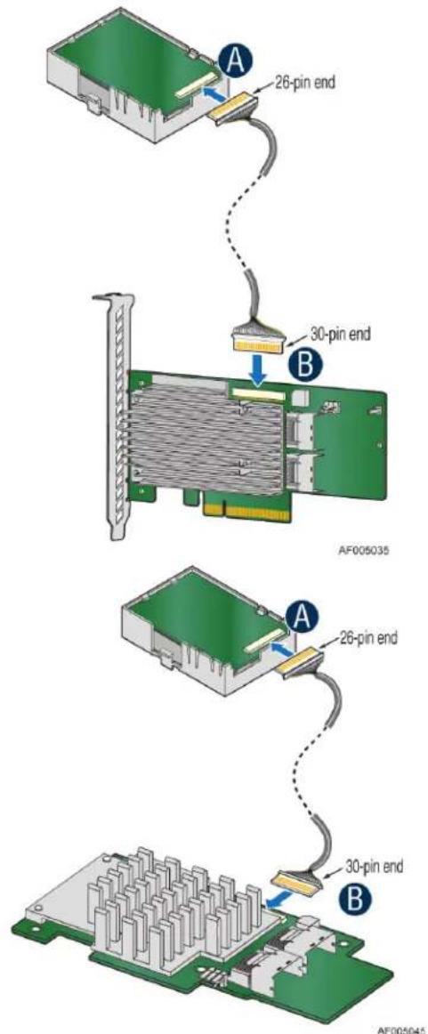
Figure 2. Connecting AXXRMFBU2 to the RAID Module
Note: Carefully observe how the cable connectors are keyed and avoid asserting unnecessary force when plugging in the cable. Do not insert at an angle. Doing so will cause connector deformation or damage.
Warning:
-
Make sure the yellow pin 1 of the cable is in alignment with the yellow mark on the board connector. Press the connector with your finger and insert with the connector parallel (see A in Figure 3). Do not try to insert cable backwards. Doing so will cause damage to the Intel ^® RAID Maintenance Free backup Unit AXXRMFBU2 and Intel ^® Integrated RAID Module.
-
Do not insert at an angle. Doing so will cause connector deformation or damage, even hardware damage to the Intel® RAID Maintenance Free backup Unit AXXRMFBU2 and Intel® Integrated RAID Module (see B in Figure 3).
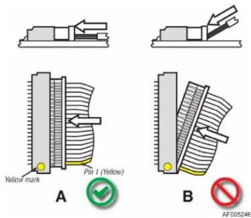
Figure 3. Connect the cable
- Secure the cable at 26-pin end with a provided Cable Twist Tie as shown in Figure 4. Note: This step is optional depends on the chassis design. Please refer to your server chassis documentation to determine if the Cable Twist Tie is needed.
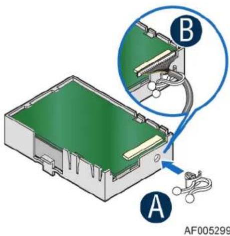
Figure 4. Installing the Cable Twist Tie
Connecting the Plastic RMFBU2 Holder to the Chassis
The Intel ^® RAID Maintenance Free Backup Unit AXXRMFBU2 is designed for easy attachment to either an Intel ^® pedestal or rack mount chassis. Complete the following instructions for your server.
If you are installing this component into a third-party chassis, you must first install an attachment mechanism, such as industrial-grade Velcro*. Refer to your server chassis documentation or discuss an appropriate attachment mechanism with your server chassis manufacturer to ensure the attachment mechanism complies with the chassis requirements.
-
Locate the installation clips inside the chassis. For the location of the installation clips, see your server system documentation. Remove the Mylar* pad if there is a Mylar* pad covering the mounting hole.
-
Align the tabs on the plastic RMFBU2 holder with the clips on the chassis (See A in Figure 5).
-
Slide the plastic RMFBU2 holder toward the front of the system until the tabs engage with the clips in the chassis (See B in Figure 5).
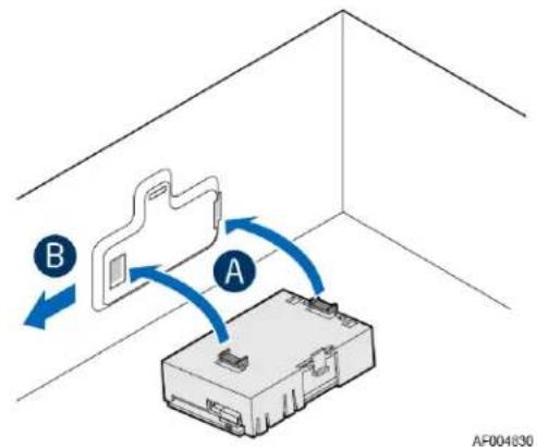
Figure 5. Connecting the Plastic RMFBU2 Holder to the Chassis
Attaching the Connecting Cable to the Server System
Follow the appropriate set of instructions below for your server:
-
Route the cable through the cable holder on the edge of the chassis.
-
Connect the cable to the RAID module.
Installing the Intel® Integrated RAID Module in the Server System
To install the Intel ^® Integrated RAID Module back into the server system, do the following: Intel ^® Integrated RAID Module RMS25PB040, RMS25PB080, RMT3PB080
-
Align the RAID module with the PCI Express* slot. To locate an appropriate slot and for instructions on installing an add-in card, see your server system documentation.
-
Press down gently, but firmly, to ensure that the RAID module is properly seated in the slot. The bottom edge of the RAID module must be flushed with the slot.
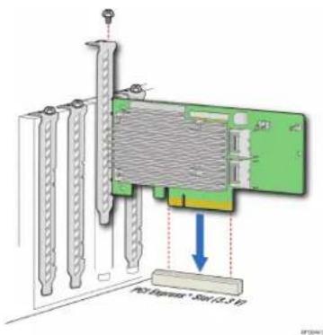
Figure 6. Seating the RAID Module
-
Connect the proper cables into the adapter using the 4-port combined end. Make sure the module and cables are properly attached and plug the cable into connector at the inside edge of the adapter.
-
Tie the RMFBU2 Cache-offload Module cable and the data cable together with a strap tie that is provided, as shown in Figure 7.
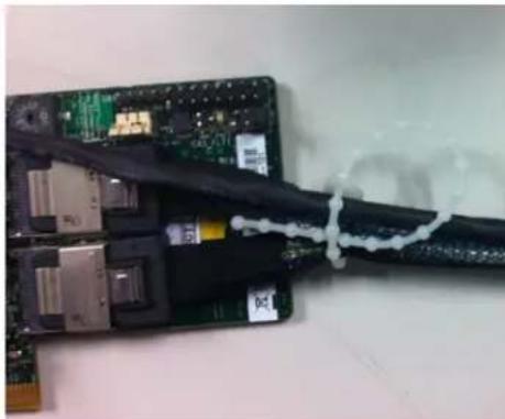
natural_image
Close-up of a damaged electronic circuit board with exposed components and a coiled cable wrapped around it (no visible text or symbols)Figure 7. Tie Together the Cables with the Strap Tie
Note: Please secure the cables with the strap tie to avoid unexpected RMFBU2 Cache-offload Module cable detaching from the RAID module during the system transportation.
- Install the server system cover back and connect the power cords. See your server system documentation for instructions.
Intel® Integrated RAID Module RMS25PB040, RMS25PB080, RMT3PB080
- Insert the four barrel standoffs into the matching holes in the server board. To locate the matching module card slot on your server board, see your server board documentation. The Intel ^ Server Board S2600IP is shown for illustrative purpose. Actual standoff hole locations could be different (see Figure 8).
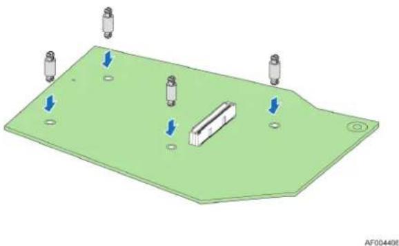
natural_image
3D CAD model of a green electronic component with four cylindrical pins and a central rectangular feature, showing mounting holes (no text or symbols)Figure 8. Installing the Barrel Standoff
- Attach the RAID to the matching server board connector, and press the module card firmly to engage the barrel standoffs installed in step 1. Press down gently but firmly to ensure that the card is properly seated in the connectors, and then insert the four pin standoffs into the barrel standoffs respectively. The Intel ^® RAID Module RM25PB080 is shown for illustrative purpose (see Figure 9).
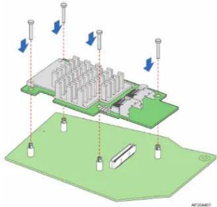
natural_image
3D diagram of a microchip or circuit board with directional arrows indicating movement or force, no text or symbols present.Figure 9. Installing the Intel® Integrated RAID Module
-
Connect the proper cables into the adapter using the 4-port combined end. Make sure the module and cables are properly attached and plug the cable into connector at the inside edge of the adapter.
-
Tie together the RMFBU2 Cache-offload Module cable and the data cable with a provided strap tie as shown in Figure 7.
Note: Please secure the cables with the strap tie to avoid unexpected RMFBU2 Cache-offload Module cable detaching from the RAID module during the system transportation.
- Install the server system cover back and connect the power cords. See your server system documentation for instructions.
3 Monitoring RAID Maintenance Free Backup Unit
Multiple utilities are available to display and configure the RMFBU2 information.
Note: This chapter describes only the RMFBU2 related features of the utility programs. For complete information on these utilities, see the Intel® RAID Software User's Guide.
Monitoring the SuperCap with the Intel® RAID BIOS Configuration Utility
The Intel ^® RAID BIOS Console can be used to configure disk arrays and logical drives. It is independent of the operating system and can be accessed at server start up by pressing
To view the RMFBU2 information, do the following:
- At boot, press
+ when prompted. - Once the Intel ^® RAID BIOS Console loads and the main menu is displayed, choose Adapter Properties.
- Click Next to view the second Adapter Properties screen.
- In the Battery Backup field at the top left of the Adapter Properties screen, click Present.
- The Battery Module screen appears, as shown in Figure 10. This screen contains the following information:
— Battery information
— Design information
— Capacity information
— Properties
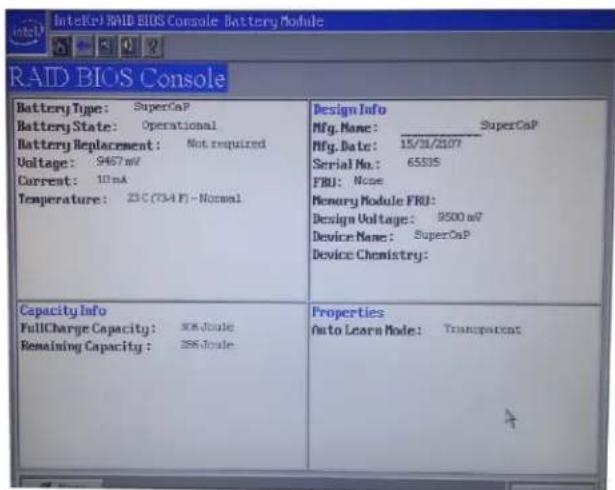
Figure 10. Monitoring the RMFBU2 with Intel® RAID BIOS Console
Note: The RMFBU2 properties are view only.
Using Intel® RAID Web Console 2
To view the status of all RMFBU2 connected to RAID modules in the server, select the Physical tab in the left panel of the Intel ^® RAID Web Console 2. To see the RMFBU2, select the controller. The RMFBU2 appears as the last item on the list under that module (see Figure 11). An icon (small green or red icon) appears in the left pane to indicate the RMFBU2 status. The green indicates normal operation and the red indicates the RMFBU2 has failed.
![RAID Web Console 2 - 11.06.00.0300 Manage Go To Log Tools Web Intel® RAID Web Console 2 Welcome administrator [Full Access] Log Off Dashboard Physica Logical Intel®Select05 Intel (R): RAID Controller RS2548080 (Bus 1,Dev 0) INTL: ID Error Level Data / Time Description 66 [Information... 2011-11-05, 00:20:10 Successful log on to the server User: administrator, Client: 127.0.0.1, Access Node: Full, Clerk Time: 2011-11-05,00:20:10 65 [Information... 2011-11-04, 23:19:53 Controller ID: 0 Time established since power on: Time 2001-11-04,23:19:53 465 Seconds 64 [Information... 2011-11-05, 23:19:53 Controller ID: 0 Battery is discharging 63 [Warning, 1] 2011-11-05, 23:19:53 Controller ID: 0 Battery relsam completed 62 [Information... 2011-11-05, 23:19:53 Controller ID: 0 Battery relsam in progress 61 [Information... 2011-11-05, 23:19:53 Controller ID: 0 Battery charge complesa 60 [Information... 2011-11-05, 23:19:53 Controller ID: 0 Battery relsam started 69 [Information... 2011-11-05, 23:19:52 Controller ID: 0 Battery relsam pending; Battery's under charge 68 [Information... 2011-11-05, 23:19:52 Controller ID: 0 Time established since power on: Time 2011-11-04,23:19:52 63 Seconds 67 [Information... 6seconds from reboot Controller ID: 0 BBU enabled; changing WT logical drives to WB 66 [Information... 1seconds from reboot Controller ID: 0 Battery temperature is normal 65 [Information... 1seconds from reboot Controller ID: 0 Battery started charging 64 [Information... 9seconds from reboot Controller ID: 0 Board Revisors: 161 63 [Information... 6seconds from reboot Controller ID: 0 Package version 23.2.1-0017 62 [Information... 6seconds from reboot Controller ID: 0 Battery Present 61 [Information... 6seconds from reboot Controller ID: 0 Image version: 3.150.05-1400 60 [Information... 6seconds from reboot Controller ID: 0 Firmware initialization started: (PCI ID 0x1000/0x005by/0x006 /0x936)) 69 [Information... 1seconds from reboot Controller ID: 0 Battery temperature is normal 68 [Information... 1seconds from reboot Controller ID: 0 Battery started charging 67 [Information... 5seconds from reboot Controller ID: 0 Board Revisors: 161 66 [Information... 5seconds from reboot Controller ID: 0 Package version 23.2.1-0017 65 [Information... 5seconds from reboot Controller ID: 0 Battery Present 64 [Information... 4seconds from reboot Controller ID: 0 Image version: 3.150.05-1400 Displaying log from server](/content/2026/05/1063076/images/1d972c74f7dcb6867fc4a06dc90849388152f8ecde890e853e8fede55d39af4a.jpg)
Figure 11. RMFBU2 Information in Intel® RAID Web Console 2
4 RAID Maintenance Free Backup Unit Specifications
MegaRAID CacheVault™ Technology
LSI* MegaRAID CacheVault™ flash cache protection uses NAND flash memory powered by a super-capacitor to protect data stored in the MegaRAID controller cache. This module eliminates the need for a lithium ion battery traditionally used to protect DRAM cache memory on PCI RAID controllers. The RAID controller automatically writes the data in cache to flash when a power failure occurs, while the super-capacitor keeps the current going during the process. When the power comes back, the DRAM is recovered from flash and the system goes on without loss of data. The benefits of this technology are elimination of hardware maintenance associated with LiON batteries, lower total cost of ownership over the life of the adapter, and more environmentally friendly cache protection.
Table 2. RMFBU2 Specifications
| Specifications RMFBU2 | |
| SuperCap2 Operating Environment | 0°C to 55°C |
| SuperCap2 Storage Temperature | 0°C to 70°C |
| Fast Charge Rate 500 mA | |
| SuperCap2 Voltage | Maximum Voltage: 13.2 VNominal Voltage: 9.5 V |
| SuperCap2 Capacity | 6.4 F (where F is the unit Farad) |
| SuperCap2 Mechanical | 65 mm x 52 mm |
| RMFBU2 Mechanical | 87 mm x 57 mm |
| SuperCap2 Charge Time | Typical: Approximately two minutes |
| RMFBU2 Shelf Life Two years | |
| RMFBU2 Warranty | Intel® provides a three year warranty on the Intel®RAID Maintenance Free Backup UnitAXXRMFBU2. |
| RMFBU2 Cache-offload Module Capacity | 2 GB NAND Flash |
| Smart Monitoring Temperature is monitored using the I | ^2C interface. |
5 Regulatory and Compliance Information
Product Regulatory Compliance
Product Safety Compliance
The Server Board SE7210TP1-E complies with the following safety requirements:
■ UL60950 – CSA 60950 (USA/Canada)
■ EN60950 (Europe)
■ IEC60950 (International)
■ CB Certificate and Report, IEC60950 (report to include all country national deviations)
■ GOST R 50377-92 – Listed on one System License (Russia)
- Belarus License – Listed on System License (Belarus)
■ CE – Low Voltage Directive 73/23/EEE (Europe)
■ IRAM Certification (Argentina)
Product EMC Compliance – Class A Compliance
Note: Legally, the product is required to comply with Class A emission requirements as it is intended for a commercial type market place. Intel targets 10db margin to Class A Limits
The Server Board SE7210TP1-E has been tested and verified to comply with the following electromagnetic compatibility (EMC) regulations when installed on a compatible Intel ^ host system. For information on compatible host system(s), refer to Intel ^® 's Server Builder website or contact your local Intel ^® representative.
■ FCC /ICES-003 Emissions – (USA/Canada) Verification
- CISPR 22 Emissions – (International)
■ EN55022 Emissions – (Europe)
■ EN55024 Immunity – (Europe)
■ CE – EMC Directive 89/336/EEC (Europe)
AS/NZS 3548 Emissions – (Australia/New Zealand)
■ BSMI CNS13438 Emissions – (Taiwan)
■ GOST R 29216-91 Emissions – Listed on one System License (Russia)
■ GOST R 50628-95 Immunity – Listed on one System License (Russia)
- Belarus License – Listed on one System License (Belarus)
■ RRL MIC Notice No. 1997-41 (EMC) and 1997-42 (EMI) (Korea)
Certifications/Registrations/Declarations
■ UL Certification (US/Canada)
■ CE Declaration of Conformity (CENELEC Europe)
■ FCC/ICES-003 Class A Attestation (USA/Canada)
■ C-Tick Declaration of Conformity (Australia)
■ MED Declaration of Conformity (New Zealand)
■ BSMI Certification (Taiwan)
■ GOST – Listed on one System License (Russia)
- Belarus – Listed on one System License (Belarus)
■ RRL Certification (Korea)
■ Ecology Declaration (International)
Product Regulatory Compliance Markings
This product is marked with the following Product Certification Markings:
Table 3. Product Certification Markings
| Regulatory Compliance | Country | Marking |
| UL Mark | USA/Canada |  US US |
| CE Mark | Europe |  |
| FCC Marking (Class A) | USA | This device complies with Part 15 of the FCC Rules. Operation of this device is subject to the following two conditions:(1) This device may not cause harmful interference, and(2) This device must accept any interference received,including interference that may cause undesired operation.Manufactured by Intel Corporation |
| EMC Marking (Class A) | Canada | CANADA ICES-003 CLASS ACANADA NMB-003 CLASSE A |
| BSMI Marking (Class A) | Taiwan |  |
| 警告使用者:這是甲類的資訊產品,在居住的環境中使用時,可能會造成射頻干擾,在這種情況下,使用者會被要求採取某些適當的對策 | ||
| RRL MIC Mark | Korea |  |
Electromagnetic Compatibility Notices
FCC (USA)
This device complies with Part 15 of the FCC Rules. Operation is subject to the following two conditions:
- This device may not cause harmful interference, and
- This device must accept any interference received, including interference that may cause undesired operation.
For questions related to the EMC performance of this product, contact:
Intel Corporation
5200 N.E. Elam Young Parkway
Hillsboro, OR 97124-6497
1-800-628-8686
This equipment has been tested and found to comply with the limits for a Class A digital device, pursuant to Part 15 of the FCC Rules. These limits are designed to provide reasonable protection against harmful interference in a residential installation. This equipment generates, uses, and can radiate radio frequency energy and, if not installed and used in accordance with the instructions, may cause harmful interference to radio communications. However, there is no guarantee that interference will not occur in a particular installation. If this equipment does cause harmful interference to radio or television reception, which can be determined by turning the equipment off and on, the user is encouraged to try to correct the interference by one or more of the following measures:
■ Reorient or relocate the receiving antenna.
■ Increase the separation between the equipment and the receiver.
- Connect the equipment to an outlet on a circuit other than the one to which the receiver is connected.
- Consult the dealer or an experienced radio/TV technician for help.
Any changes or modifications not expressly approved by the grantee of this device could void the user's authority to operate the equipment. The customer is responsible for ensuring compliance of the modified product.
Only peripherals (computer input/output devices, terminals, printers, and so on) that comply with FCC Class A or B limits may be attached to this computer product. Operation with noncompliant peripherals is likely to result in interference to radio and TV reception.
All cables used to connect to peripherals must be shielded and grounded. Operation with cables, connected to peripherals that are not shielded and grounded may result in interference to radio and TV reception.
Industry Canada (ICES-003)
This digital apparatus does not exceed the Class A limits for radio noise emissions from digital apparatus set out in the interference-causing equipment standard entitled: “Digital Apparatus,” ICES-003 of the Canadian Department of Communications.
Europe (CE Declaration of Conformity)
This product has been tested in accordance too, and complies with the Low Voltage Directive (73/23/EEC) and EMC Directive (89/336/EEC). The product has been marked with the CE Mark to illustrate its compliance.
Taiwan Declaration of Conformity (BSMI)
The BSMI Certification Marking and EMC warning is located on the outside rear area of the product.
Korean Compliance (RRL)

English translation of the notice above:
- Type of Equipment (Model Name): On License and Product
- Certification No.: On RRL certificate. Obtain certificate from local Intel ^® representative
- Name of Certification Recipient: Intel Corporation
- Date of Manufacturer: Refer to date code on product
- Manufacturer/Nation: Intel Corporation/Refer to country of origin marked on product
World Wide Web
http://www.intel.com/p/en_US/support/server/
Telephone
All calls are billed US \25.00 per incident, levied in local currency at the applicable credit card exchange rate plus applicable taxes. (Intel^{\textregistered}$ reserves the right to change the pricing for telephone support at any time without notice).
Before calling, fill out the Intel ^® Server Issue Report Form. A sample form is provided on the following pages. However, for the fastest service, please submit your form over the Internet.
| In U.S. and Canada | 1-800-404-2284 | |
| In Europe | ||
| UK 0870 6072439 | Finland 9 693 79297 | |
| France 01 41 918529 | Denmark 38 487077 | |
| Germany 069 9509 6099 | Norway 23 1620 50 | |
| Italy 02 696 33276 | Sweden 08 445 1251 | |
| Spain 91 377 8166 | Holland 020 487 4562 | |
| Belgium 02 714 3182 | ||
| In Asia-Pacific region | ||
| Australia 1800 649931 | Indonesia | 803 65 7249 |
| Hong Kong 852 2 844 4456 | Malaysia | 1 800 80 1390 |
| Korea 822 767 2595 | New Zealand | 0800 444 365 |
| China 800 820 1100 (toll-free) | Pakistan | 632 63684 15 (IDD from Philippines) |
| 8 621 33104691 (not toll-free) | Philippines | 1 800 1 651 0117 |
| Singapore 65 6213-1311 | Thailand | 1 800 631 0003 |
| India 0006517 2 68303634 (manual toll-free. From India, you need an IDD-equipped telephone) | Vietnam | 632 6368416 (IDD from Philippines) |
| Myanmar | 63 2 636 9796 (from Philippines) | |
| Cambodia | 63 2 636 9797 (from Philippines) | |
| Taiwan 2 2545-1640 | ||
| In Japan | ||
| 0120 868686 (Domestic) | 81 298 47 0800 (outside country) | |
In Latin America
| Brazil 001-916 377 0180 | |
| Mexico | Contact AT&T USA at 001 800462 628 4240. Once connected,dial 800 843 4481 |
| Colombia | Contact AT&T USA at 01 800911 0010. Once connected, dial800 843 4481 |
| Costa Rica | Contact AT&T USA at 0 800 0114 114. Once connected, dial800 843 4481 |
| Panama | Contact AT&T USA at 00 800001 0109. Once connected, dial800 843 4481 |
| Chile (Easter Island) | Contact AT&T USA at 800 800 311. Onceconnected, dial 800 843 4481 |
| Chile (Mainland and Juan) | Contact AT&T USA at 800 225 288. Onceconnected, dial 800 843 4481 |
| Miami | 1 800 621 8423 |
| Ecuador (Andimate) | Contact AT&T USA at 1 999 |
| 119. Once connected, dial 800 843 4481 | |
| Ecuador (Pacifictel) | Contact AT&T USA at 1 800 |
| 225 528. Once connected, dial 800 843 4481 | |
| Guatemala | Contact AT&T USA at 99 99 190. Once connected, dial 800 843 4481 |
| Venezuela | Contact AT&T USA at 0 800 2255 288. Once connected, dial 800 843 4481 |
| Argentina | Contact AT&T USA at 0-800 222 1288. Once connected, dial 800 843 4481 |
| Paraguay | 001 916 377 0114 |
| Peru | 001 916 377 0114 |
| Uruguay | 001 916 377 0114 |
For an updated support contact list, see http://www.intel.com/support/9089.htm/.
6 Intel® Server Issue Report Form
Date Submitted:
Company Name: ____
Contact Name:
Email Address:
Intel ^® Server Product:
Priority (Critical, Hot, High, Low): ____
Brief Problem Description. Provide a brief description below. See the last page for space to include a detailed problem description.
Board/Chassis Information
| Baseboard Revision – PBA#: | DIMM Configuration |
| Baseboard Serial Number: | DIMM1A MB: |
| CPU1 Speed/Stepping/Spec: | DIMM1A Vendor/part number: |
| CPU2 Speed/Stepping/Spec: | DIMM1B MB: |
| System BIOS Version: | DIMM1B Vendor/part number: |
| HSC Firmware Version: | DIMM2A MB: |
| Chassis Model | DIMM2A Vendor/part number: |
| Intel ^ SC5200 Base | DIMM2B MB: |
| Intel ^ SC5200 BaseRedundant Power | DIMM2B Vendor/part number: |
| Intel ^ SC5250-E | |
| Intel ^ SR1350-E | |
| Other (Vendor/Model): |
Operating System Information
Operating System ____
Version
Service Pack
Peripheral Information
Check each box below that is used, and provide the requested information.
| Peripheral | Card Or Peripheral Description | Driver Revision | IRQ # | I/O Base Address | FW Rev# |
| P64 Segment C (PCI-X 64/133) | |||||
| ☐ PCI Slot 1 | |||||
| ☐ PCI Slot 2 | |||||
| P64 Segment B (PCI-X 64/100) | |||||
| ☐ PCI Slot 3 | |||||
| ☐ PCI Slot 4 | |||||
| P32 Segment A (PCI 32/33) | |||||
| ☐ PCI Slot 5 | |||||
| ☐ PCI Slot 6 | |||||
| Video | |||||
| ☐ On-Board Video | |||||
| ☐ Add-in Video | |||||
| NIC | |||||
| ☐ On-Board NIC1(10/100 Mb) | |||||
| ☐ On-Board NIC2(1.0 Gb) | |||||
Hard Drive Information:
☐ IDE # of drives installed: ____
Make/Model/Firmware Revision
☐ SCSI # of drives installed: ____
Make/Model/Firmware Revision ____
☐ SATA # of drives installed: ____
Make/Model/Firmware Revision
Complete Problem Description
In the space below, provide a complete description of the steps used to reproduce the problem or a complete description of where the problem can be found. Please also include any details on troubleshooting already done.