
MSR3012 - Router HP - Free user manual and instructions
Find the device manual for free MSR3012 HP in PDF.


| Product Type | Router |
| Brand | HP (Hewlett Packard Enterprise) |
| Model | MSR3012 |
| Form Factor | Modular router with SIC, DSIC, MIM, XMIM, HMIM, FIC, DFIC slots |
| Supported Interface Modules | Ethernet, E1/T1, E3/T3, ATM, POS, CPOS, xDSL, ISDN, Serial, Voice, WLAN, 3G/4G |
| PoE Support | Yes (with PoE-capable interface modules) |
| Operating System | HPE Comware |
| Operating Temperature | 0°C to 45°C (32°F to 113°F) |
| Storage Temperature | -40°C to 70°C (-40°F to 158°F) |
| Safety Compliance | Compliant with international safety standards |
| Maintenance | Field-replaceable interface modules; hot-swappable (if supported) |
| Repairability | Modular design allows easy replacement of components |
| Warranty | Standard HP warranty (see documentation) |
| Dimensions | 1U rackmount (typical); exact dimensions vary by configuration |
Frequently Asked Questions - MSR3012 HP
User questions about MSR3012 HP
0 question about this device. Answer the ones you know or ask your own.
Ask a new question about this device
Download the instructions for your Router in PDF format for free! Find your manual MSR3012 - HP and take your electronic device back in hand. On this page are published all the documents necessary for the use of your device. MSR3012 by HP.
USER MANUAL MSR3012 HP
HPE FlexNetwork MSR Router Series Interface Module Guide
© Copyright 2016 Hewlett Packard Enterprise Development LP
The information contained herein is subject to change without notice. The only warranties for Hewlett Packard Enterprise products and services are set forth in the express warranty statements accompanying such products and services. Nothing herein should be construed as constituting an additional warranty. Hewlett Packard Enterprise shall not be liable for technical or editorial errors or omissions contained herein.
Confidential computer software. Valid license from Hewlett Packard Enterprise required for possession, use, or copying. Consistent with FAR 12.211 and 12.212, Commercial Computer Software, Computer Software Documentation, and Technical Data for Commercial Items are licensed to the U.S. Government under vendor's standard commercial license.
Links to third-party websites take you outside the Hewlett Packard Enterprise website. Hewlett Packard Enterprise has no control over and is not responsible for information outside the Hewlett Packard Enterprise website.
Acknowledgments
Intel®, Itanium®, Pentium®, Intel Inside®, and the Intel Inside logo are trademarks of Intel Corporation in the United States and other countries.
Microsoft® and Windows® are trademarks of the Microsoft group of companies.
Adobe® and Acrobat® are trademarks of Adobe Systems Incorporated.
Java and Oracle are registered trademarks of Oracle and/or its affiliates.
UNIX® is a registered trademark of The Open Group.
Contents
SIC/DSIC 1
Ethernet switching module 1
SIC-4FSW/SIC-4FSW-PoE/DSIC-9FSW/DSIC-9FSW-PoE 1
SIC-4GSW/SIC-4GSW-POE 2
For more information about the Ethernet interface cables and connection methods, see "Ethernet
interface."Ethernet interface module 3
SIC-1FEA 4
SIC-1FEF 4
SIC-1GEC-V2/SIC-1GEC-H3 5
E1/T1 interface module 7
SIC-1E1-F 7
SIC-2E1-F 8
SIC-4G-LTE-A/SIC-4G-LTE-G 37
MIM/DMIM/XMIM 40
Ethernet switching module 40
XMIM-16FSW/XMIM-24FSW 40
MIM-16FSW/MIM-16FSW-PoE/DMIM-24FSW/DMIM-24FSW-PoE 41
Ethernet interface module 43
MIM-2FE/MIM-4FE 43
MIM-2GBE 44
ATM interface module 45
MIM-1ATM-OC3 45
MIM-IMA-8E1 46
MIM-IMA-4T1 47
POS (SDH/SONET) interface module 48
MIM-1POS 48
E1/T1 interface module 49
MIM-2E1/MIM-4E1/MIM-4E1-F modules 49
MIM-8E1/MIM-8E1-F 51
MIM-2T1/MIM-4T1-F 52
MIM-8T1/MIM-8T1-F 53
E3/T3 interface module 55
MIM-1CE3 55
MIM-1CT3 56
xDSL interface module 57
MIM-1SHL-4W 57
Serial interface module 58
MIM-2SAE/MIM-4SAE/MIM-8SAE 59
MIM-8ASE/MIM-16ASE 60
Voice interface module 61
MIM-16FXS 62
MIM-4BSV 62
MIM-2FXO and MIM-4FXS/MIM-4FXO 64
MIM-4E&M 65
MIM-1VE1 66
MIM-1VT1 67
MIM-2VE1 68
MIM-2VT1 69
HMIM 71
Ethernet interface switching module 71
HMIM-8GSW/HMIM-24GSW/HMIM-24GSW-PoE 71
RT-HMIM-8GSWF 72
Ethernet interface module 73
HMIM-2GEE/HMIM-4GEE/HMIM-8GEE 73
HMIM-2GEF/HMIM-4GEF/HMIM-8GEF 74
POS (SDH/SONET) interface module 75
HMIM-1POS 75
CPOS (SDH/SONET) interface module 76
HMIM-1CPOS 76
E1/T1 interface module 77
HMIM-2E1/HMIM-4E1/HMIM-4E1-F 78
HMIM-8E1 79
HMIM-4SAE/HMIM-8SAE 86
HMIM-16ASE 88
Voice interface module 88
HMIM-16FXS 89
HMIM-2VE1 90
HMIM-2VT1 91
HMIM-1VE1 92
HMIM-1VT1 93
HMIM-4FXS/HMIM-4FXO 94
HMIM-4E&M 95
FIC/DFIC 96
Ethernet switching module 96
FIC-16FSW/FIC-16FSW-PoE/DFIC-24FSW/DFIC-24FSW-PoE 96
Ethernet interface module 98
FIC-2FE/FIC-4FE 98
FIC-1GBE/FIC-2GBE 99
FIC-1GEF/FIC-2GEF 100
ATM interface module 101
FIC-IMA-4E1/FIC-IMA-8E1 102
FIC-IMA-8T1 103
FIC-1AE3 104
FIC-1AT3....105
FIC-1ATM-OC3 106
POS (SDH/SONET) interface module 107
FIC-1POS 107
CPOS (SDH/SONET) interface module 108
FIC-1CPOS 108
E1/T1 interface module 109
FIC-2E1/FIC-4E1 and FIC-4E1-F 109
FIC-8E1 111
FIC-4T1-F 112
E3/T3 interface module 113
FIC-1CE3 113
FIC-1CT3 114
ISDN BRI interface module 116
FIC-4BSE 116
Serial interface module 118
FIC-4SAE/FIC-8SAE 118
FIC-8ASE/FIC-16ASE 120
Voice interface module 121
FIC-4FXS/FIC-4FXO 122
FIC-4E&M 123
FIC-24FXS 124
FIC-2VE1 124
FIC-2VT1 125
FIC-1VE1 127
FIC-1VT1 128
ESM/VCPM/VPM 130
ESMs 130
ESM-ANDE 130
ESM-SNDE 131
VCPM/VPM 131
VCPM/VPM purchase guide 131
VCPM 132
VPM 133
Cables and connection methods.... 134
Ethernet interface 134
Fiber port 136
E1 interface 141
T1 interface 149
E3/T3 interface 152
Synchronous/asynchronous serial ports 152
Asynchronous serial ports 155
ADSL/BS/FXS/FXO/AM/FCM interface 160
E&M interface 161
24FXS interface 163
BSV/BSE interface 164
G.SHDSL interface 166
WLAN interface 168
3G interface 169
4G interface 170
Appendix A Interface module list 172
Appendix B Purchase guide 177
SIC/DSIC purchase guide 177
MIM/XMIM/DMIM purchase guide 182
HMIM purchase guide 183
FIC/DFIC purchase guide 185
ESM/VPM/VCPM purchase guide 186
Index 188
SIC/DSIC
MSR series routers use modular design and support a wide range of SICs and DSICs. A SIC occupies one SIC slot and a DSIC occupies two SIC slots. The SIC/DSIC series interface modules provide interfaces such as synchronous/asynchronous serial interface, Ethernet interface, E1/T1, ISDN BRI/PRI, ADSL, audio interface, and Layer 2 switching interface.
Among this series interface modules, the Layer 2 switching interface modules (SIC-4FSW and DSIC-9FSW) each have a corresponding PoE-capable module. The module can provide -48 VDC power to remote powered devices (PDs, such as IP phone, WLAN AP, network camera) through straight-through cables if it is installed in a PoE router.
Ethernet switching module
- SIC-4FSW
- SIC-4FSW-PoE
- DSIC-9FSW
- DSIC-9FSW-PoE
- SIC-4GSW
- SIC-4GSW-PoE
SIC-4FSW/SIC-4FSW-PoE/DSIC-9FSW/DSIC-9FSW-PoE
Introduction
The 4/9-port 10/100 Mbps Ethernet Layer 2 interface modules SIC-4FSW/SIC-4FSW-PoE and DSIC-9FSW/DSIC-9FSW-PoE can provide up to 4/9 10/100 Base-Tx Ethernet ports for Layer 2 and Layer 3 switching. A router installed with SIC-4FSW/DSIC-9FSW modules can work as a switching/routing integrated device on a small-sized enterprise network to connect PCs and network devices inside the network. The SIC-4FSW-PoE/DSIC-9FSW-PoE interface modules can supply power to powered devices (PDs) through power over Ethernet (PoE).
Interface specifications
Table 1 Interface specifications
| Item | Specification | |
| SIC-4FSW/SIC-4FSW-PoE | DSIC-9FSW/DSIC-9FSW-PoE | |
| Connector | RJ-45 | |
| Interface type MDI/MDIX | ||
| Number of connectors | Four 100 Mbps RJ-45 connectors Nine 100 Mbps RJ-45 connectors | |
| Transmission distance | 100 m (328.08 ft) over category-5 twisted pair cables (both crossover and straight-through) | |
| Operating mode 10/100 Mbps autosensing, full/half duplex | ||
Interface LEDs
Figure 1 SIC-4FSW panel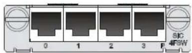
Figure 2 SIC-4FSW-PoE panel
Figure 3 DSIC-9FSW panel
Figure 4 DSIC-9FSW-PoE panel
Table 2 LED description
| LED | Description |
| Steady green A link is present. | |
| Off No link is present. | |
| Flashing green Data is being transmitted and received (ACT). | |
In addition, the SIC-4FSW-POE and DSIC-9FSW-POE each provide a PoE LED.
Table 3 LED description
| LED | Description |
| Steady green The module is supplying power to PDs. | |
| Flashing green at 8 Hz | An alarm has occurred on the ports that connects to the PDs. |
| Off The module is not supplying power to any PDs. | |
Interface cables and connection methods
For more information about the Ethernet interface cables and connection methods, see "Ethernet interface."
SIC-4GSW/SIC-4GSW-POE
Introduction
The 4-port 1000 Mbps Ethernet Layer 2 SIC interface module SIC-4GSW/SIC-4GSW-POE provides four 1000 Mbps RJ-45 connectors. It is designed for switching/routing integrated routers on a small-sized enterprise network. You can use it to connect PCs and network devices inside the network. The SIC-4GW-PoE interface module can supply power to PDs through PoE.
small-sized enterprise network. You can use it to connect PCs and network devices inside the network. The SIC-4GW-PoE interface module can supply power to PDs through PoE.
Interface specifications
Table 4 Interface specifications
| Item | Specification |
| Connector | RJ-45 |
| Interface type MDI/MDIX | |
| Number of connectors 4 | |
| Transmission distance | 100 m (328.08 ft) over category-5 twisted pair cables (both crossover and straight-through) |
| Operating mode 10/100/1000 Mbps autosensing, full/half duplex | |
Interface LEDs
Figure 5 SIC-4GSW
Figure 6 SIC-4GSW-PoE
Table 5 LED description
| LED | Description |
| Off | No link is present. |
| Steady green | A 1000 Mbps link is present. |
| Flashing green | The interface is sending or receiving data at 1000 Mbps. |
| Steady yellow | A 10/100 Mbps link is present. |
| Flashing yellow | The interface is sending or receiving data at 10/100 Mbps. |
Interface cables and connection methods
For more information about the Ethernet interface cables and connection methods, see "Ethernet interface."Ethernet interface module
- SIC-1FEA
- SIC-1FEF
- SIC-1GEC-V2
- SIC-1GEC-H3
SIC-1FEA
Introduction
The 1-port 10Base-T/100Base-TX Ethernet interface module (SIC-1FEA) implements communication between Routers and LANs.
Interface specifications
Table 6 Interface specifications
| Item | Specification |
| Connector | RJ-45 |
| Interface type MDI | |
| Number of connectors 1 | |
| Transmission distance | 100 m (328.08 ft) over category-5 twisted pair cables (both crossover and straight-through) |
| Operating mode 10/100 Mbps autosensing, full | duplex/half duplex |
Interface LEDs
Figure 7 SIC-1FEA panel
Table 7 LED description
| LED | Description |
| LINK | Off means no link is present;On means a link is present. |
| ACT | Off means no data is being transmitted or received;Flashing means data is being received or/and transmitted. |
Interface cables and connection methods
For more information about the Ethernet interface cables and connection methods, see "Ethernet interface."
SIC-1FEF
Introduction
The 1-port 100 Mbps fiber Ethernet interface module (SIC-1FEF) implements communication between the router and LAN.
Interface specifications
Table 8 Interface specifications
| Item | Specification |
| Number of connectors | 1 |
| Connector | SFP/LC |
| Interface standard | 802.3, 802.3u, and 802.3ab |
| Operating mode | 100 Mbps, full duplex |
Interface LEDs
Figure 8 SIC-1FEF panel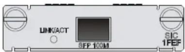
Table 9 LED description
| LED | Status | Description |
| LINK/ACT | Off No link is present. | |
| Steady green A link is present. | ||
| Flashing green Data is being received and transmitted at 100 Mbps. | ||
| Steady yellow Information detection failed. |
Fiber ports, optical fibers, and the connection methods
For more information about fiber ports, optical fibers, and the connection methods, see "Fiber port."
SIC-1GEC-V2/SIC-1GEC-H3
Introduction
The 1-port 10/100/1000 Mbps copper and fiber Ethernet interface module
SIC-1GEC-V2/SIC-1GEC-H3 provides the following features:
• Receipt, transmission and processing of GE data stream. - CE copper and fiber interface access. • 1000/100/10 Mbps on the copper interface. • 1000 Mbps on the fiber interface.
Interface specifications
Table 10 Interface specifications
| Item | Specification |
| Connector | RJ-45 |
| Interface type MDI | |
| Frame format | Ethernet_IIEthernet_SNAPIEEE 802.2IEEE 802.3 |
| Operating mode 10/100/1000 Mbps autosensing, full/half duplex | |
NOTE:
The SIC-1GEC-V2/SIC-1GEC-H3 provides an interface that combines a fiber port and a copper port. Only one port of the combo interface can be activated at a time. The copper port is activated by default. To use the fiber port, execute the related command at the command line interface (CLI).
Interface LEDs
Figure 9 SIC-1GEC-H3 panel
Figure 10 SIC-1GEC-V2 panel
Table 11 LED description for the SIC-1GEC-V2/SIC-1GEC-H3
| LED | Description |
| LINK | On means carrier signal is received.Off means no carrier signal is received.Green: Data is being received and transmitted at a speed of 1000 Mbps.Yellow: Data is being received and transmitted at a speed of 100/10 Mbps. |
| ACT | Off: No data is being received and transmitted.Flashing: Data is being received and transmitted. |
Table 12 LED description for the SIC-1GEC-V2/SIC-1GEC-H3
| LED | Description |
| LINK | On means carrier signal is received.Off means no carrier signal is received.Green: Data is being received and transmitted at a speed of 1000 Mbps.Yellow: The module is faulty. |
| ACT | Off: No data is being received and transmitted.Flashing: Data is being received and transmitted. |
Interface cables and connection methods
For more information about the Ethernet interface cables and connection methods, see "Ethernet interface."
E1/T1 interface module
- SIC-1E1-F
- SIC-2E1-F
- SIC-EPRI
- SIC-1EPRI
- SIC-1T1-F
SIC-1E1-F
Introduction
The 1-port fractional E1 interface module (SIC-1E1-F) provides the following features:
• Transmission, receiving, and handling of E1 data streams • CE1 (channelized E1) access - Remote loopback and local loopback functions, facilitating fault test and location
The FE1 operating mode supported by the SIC-1E1-F module allows only one bundle. The time slots can only be bundled into one n x 64 kbps channel, where n is in the range of 1 to 31.
The SIC-1E1-F does not support the PRI mode.
Interface specifications
Table 13 Interface specifications
| Item Specification | |
| Connector type | D15 |
| Number of connectors | 1 |
| Interface standard | G.703, G.704 |
| Interface rate | 2.048 Mbps |
| Cable type | 75-ohm unbalanced coaxial cable (D15 to BNC) |
| Operating modes | E1CE1 |
| Supported services | BackupTerminal access |
Interface LEDs
Figure 11 SIC-1E1-F panel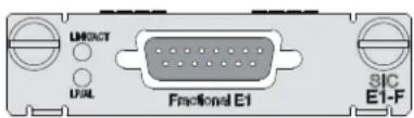
Table 14 LED description
| LED | Description |
| LINK/ACT | On means carrier signal has been received.Flashing means data is being transmitted or received.Off means no carrier signal has been received. |
| LP/AL | On means the interface is in a loopback.Flashing means an AIS, LFA, or RAI alarm signal is present.Off means neither loopback nor alarm is present. |
| Note:AIS = Alarm indication signal; LFA = loss of frame alignment; RAI = Remote alarm indication | |
Interface cables and connection methods
For more information about E1 interface cables, see "E1 interface."
SIC-2E1-F
Introduction
The 2-port fractional E1 interface module (fractional) provides the following features:
• Transmission/Receiving and handling of E1 data streams • CE1 (channelized E1) access - Remote loopback and local loopback functions, facilitating fault test and location.
The FE1 operating mode supported by the SIC-2E1-F module allows only one bundle. The time slots can only be bundled into one n x 64 kbps channel, where n is in the range of 1 to 31.
The SIC-2E1-F does not support the PRI mode.
Interface specifications
Table 15 Interface specifications
| Item Specification | |
| Connector type | D15 |
| Number of connectors | 1 |
| Interface standard | G.703, G.704 |
| Interface rate | 2.048 Mbps |
| Cable type | 75-ohm unbalanced coaxial cable (D15 to BNC) |
| Operating modes | E1CE1 |
| Supported services | BackupTerminal access |
Interface LEDs
Figure 12 SIC-2E1-F panel
Table 16 LED description
| LED | Description |
| LINK/ACT | On means carrier signal has been received.Flashing means data is being transmitted or received.Off means no carrier signal has been received. |
| LP/AL | On means the interface is in a loopback.Flashing means an AIS, LFA, or RAI alarm signal is present.Off means neither loopback nor alarm is present. |
| Note:AIS = Alarm indication signal; LFA = loss of frame alignment; RAI = Remote alarm indication | |
Interface cables and connection methods
For more information about E1 interface cables, see "E1 interface."
SIC-EPRI/SIC-1EPRI
Introduction
The 1-port E1/CE1/PRI SIC interface module (SIC-EPRI/SIC-1EPRI) provides the following features:
• Transmission/Receiving and handling of E1 data streams. • CE1 (channelized E1) access. - ISDN PRI. - Remote loopback and local loopback functions, facilitating fault test and location.
Interface specifications
Table 17 Interface specifications
| Item Specification | |
| Connector type | D15 |
| Number of connectors | 1 |
| Interface standard | G.703, G.704 |
| Interface rate | 2.048 Mbps |
| Cable type | 75-ohm unbalanced coaxial cable (D15 to BNC)Coaxial connector, network interface connector, and 75-to-120-ohm adaptor (with BNC connector) |
| Operating modes | E1CE1ISDN PRI |
| Supported services | BackupTerminal accessISDN |
Interface LEDs
Figure 13 SIC-EPRI/SIC-1EPRI panel
Table 18 LED description
| LED | Description |
| LINK/ACT | On means carrier signal has been received.Flashing means data is being transmitted or received.Off means no carrier signal has been received. |
| LP/AL | On means the interface is in a loopback.Flashing means an AIS, LFA, or RAI alarm signal is present.Off means neither loopback nor alarm is present. |
| Note:AIS = Alarm indication signal; LFA = loss of frame alignment; RAI = Remote alarm indication | |
Interface cables and connection methods
A 70-to-120-ohm adaptor is required to connect a 120-ohm cable to the 75-ohm SIC-1EPRI. For more information about E1 interface cables, see "E1 interface."
SIC-1T1-F
Introduction
1-port Fractional T1 interface module provides the following features:
• Transmission/Receiving and handling of T1 data streams. • Remote loopback and local loopback, facilitating the effective and flexible debugging.
The FT1 operating mode supported by the SIC-1T1-F module allows only one bundle. The time slots can only be bundled into one n x 56 kbps channel, where n is in the range of 1 to 24.
The SIC-1T1-F does not support the PRI mode.
Interface specifications
Table 19 Interface specifications
| Item Specification | |
| Connector type | RJ-45 |
| Number of connectors | 1 |
| Interface standard | G.703/T1.102G.704AT&T TR 54016AT&T TR 62411ANSI T1.403 |
| Interface rate | 1.544 Mbps |
| Cable type | T1 cable (100-ohm standard shielded network cable) |
| Operating mode | FT1 |
| Supported service | BackupTerminal access |
Interface LEDs
Figure 14 SIC-1T1-F panel
Table 20 LED description
| LED | Description |
| LINK/ACT | On means the carrier signal has been received.Off means no carrier signal has been received.Flashing means data is being transmitted or/and received. |
| LP/AL | On means the interface is in a loopback.Flashing means an AIS, LFA, or RAI alarm signal is present.Off means no loopback or alarm is present. |
| Note:AIS = Alarm indication signal; LFA = loss of frame alignment; RAI = Remote alarm indication | |
Interface cables and connection methods
For more information about T1 interface cables and connection methods, see "T1 interface."
Serial interface module
The 8-port asynchronous serial interface module (SIC-8AS) transmits and processes asynchronous data streams.
The SIC-8AS provides the following features:
• Each asynchronous serial port provides a rate up to 115.2 Kbps. • Supports the terminal access service and asynchronous dedicated line. • Acts as the small-/medium-sized ISP dial-up access server when an asynchronous serial port is used for dial-up.
Interface specifications
Table 21 Interface specifications
| Item | Specification |
| Connector | DB60 |
| Number of connectors 1 | |
| Interface cable Customized cable with 8-port RJ-45 connector | |
| Interface standard RS232 | |
| Minimum baud rate 300 bps | |
| Maximum baud rate 115.2 Kbps | |
| Supported services | Modem dial-upBackupTerminal access serviceAsynchronous dedicated line |
Interface LEDs
Figure 15 SIC-8AS front panel
Table 22 LED description
| LED | Description |
| LINK/ACT | Off means no link is present;On means a link is present.Flashing means data is being received or/and transmitted. |
Interface cables and connection methods
For more information about asynchronous serial port cables, see "Asynchronous serial ports."
SIC-16AS
Introduction
The 16-port asynchronous serial interface module (SIC-16AS) transmits and processes asynchronous data streams.
The SIC-16AS provides the following features:
• Each asynchronous serial port supports a rate of up to 115.2 Kbps. • Supports terminal access service and asynchronous dedicated line. - Acts as a small- or medium-sized ISP dial-up access server when an asynchronous serial port is used for dial-up.
Interface specifications
Table 23 Interface specifications
| Item | Specification |
| Connector | D28 (male) |
| Number of connectors 1 | |
| Interface cable Customized cable with 16-port RJ-45 connector (female) | |
| Interface standard RS232 | |
| Minimum baud rate 300 bps | |
| Maximum baud rate 115.2 Kbps | |
| Supported services | Modem dial-upBackupTerminal access serviceAsynchronous dedicated line |
Interface LEDs
Figure 16 SIC-16AS panel
Table 24 LED description
| LED | Description |
| LINK/ACT | Off means no link is present;On means a link is present.Flashing means data is being received or/and transmitted. |
Interface cables and connection methods
For more information about asynchronous serial port cables, see "Asynchronous serial ports."
SIC-1SAE/SIC-2SAE/SIC-4SAE
Introduction
The 1-port/2-port/4-port enhanced high-speed synchronous/asynchronous serial interface module (SIC-1SAE/SIC-2SAE/SIC-4SAE) provides features similar to SA, but its serial interfaces support additional protocols, such as RS449, X.21, and RS530.
Interface specifications
Table 25 Interface specifications
| Item | Specification | ||
| Synchronous | Asynchronous | ||
| Connector | D28 | ||
| Number of connectors | 1 (SIC-1SAE)2 (SIC-2SAE)4 (SIC-4SAE) | ||
| Interface standard and operating mode | V.24 | V.35, RS449, X.21, RS530 | RS232 |
| DTE, DCE DTE, DCE | |||
| Minimum baud rate (bps) | 1200 | 1200 | 300 |
| Maximum baud rate (bps) | 64 k 2.048 M | 115.2 | |
| Cable | V.24 (RS232) DTE cableV.24 (RS232) DCE cableV.35 DTE cableV.35 DCE cableX.21 DTE cableX.21 DCE cableRS449 DTE cableRS449 DCE cableRS530 DTE cableRS530 DCE cable | ||
| Supported service | DDN leased lineTerminal access service | Dialup through modemsBackupAsynchronous leased lineTerminal access | |
Interface LEDs
Figure 17 SIC-1SAE panel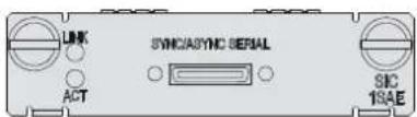
Figure 18 SIC-1SAE panel
Figure 19 SIC-1SAE panel
Table 26 LED description
| LED | Description |
| LINK | Off means no link is present.On means a link is present. |
| ACT | Off means no data is being transmitted or received.Flashing means data is being received or/and transmitted. |
Interface cables and connection methods
For more information about synchronous/asynchronous serial port cables and connection methods, see "Synchronous/asynchronous serial ports."
XDSL interface module
- DSIC-1SHDSL-8W
- SIC-1ADSL
- SIC-1ADSL-I
DSIC-1SHDSL-8W
Introduction
The 1-port 8-wire (4-pair) high-speed digital subscriber line interface module (DSIC-1SHDSL-8W) supports symmetric link rate of up to 22.76 Mbps.
The G.SHDSL provides symmetric uplink and downlink and transmission rates of 192 kbps to 2312 kbps. Developed from G.SHDSL, the G.SHDSL.BIS provides a higher-speed negotiation rate and supports scalability of multi-pair wires in addition to the functions of the G.SHDSL.
The DSIC-1SHDSL-8W provides the following features:
• Communications in ATM/EFM mode. • Manual and automatic switchover between ATM and EFM modes. • Supports using four, three, two, and one pair(s) of wires.
Interface specifications
Table 27 Interface specifications
| Item | Specification |
| Connector | RJ-45 |
| Number of connectors 1 | |
| Interface standard | ITU-T G991.2 ANNEX A, ANNEX B, ANNEX F, ANNEX GITU-T G994.1 handshaking |
| Interface rate | 5.69 Mbps (1 pair mode)11.38 Mbps (2 pair mode)17.07 Mbps (3 pair mode)22.76 Mbps (4 pair mode) |
| Cable | Telephone cable with ferrite core (one RJ-45 connector converts to two RJ-11 connectors.) |
| Operating mode | ATMEFM |
| Supported services G.SHDSL over the regular telephone line | |
Interface LEDs
Figure 20 DSIC-1SHDSL-8W panel
Table 28 LED description
| LED | Description |
| LINK/ACT (P0-P3) | On means a carrier signal is received.Off means no carrier signals is received.Fast flashing means data is being received or/and transmitted.Slow flashing means the module is negotiating rates. |
Interface cables and connection methods
For more information about G.SHDSL interface cables and connection methods, see "G.SHDSL interface."
SIC-1ADSL
Introduction
The 1-port ADSL over PSTN interface module (SIC-1ADSL) provides an RJ-11 interface that can work as a WAN interface. It allows a LAN subscriber to connect to the digital subscriber's loop access multiplexer (DSLAM) at the central office over a regular analog subscriber line or telephone line. Therefore, the subscriber can access the ATM/IP backbone or the Internet to use services such as high-speed data communication and video on demand (VoD).
ADSL transmits data in the high frequency band above 26 kHz. Therefore, it can provide services without interfering with the voice service being provided in the low frequency band (0 to 4 kHz) on the same line. It provides downlink rates in the range 32 kbps to 8 Mbps and uplink rates in the range 32 kbps to 1 Mbps.
The SIC-1ADSL provides the following features:
- Manual ADSL line activation and deactivation, which provides a convenient method for fault location.
• Interface standards of G. DMT, G. Lite, and T1.413, auto-sensing. - Trellis coding (except for G. Lite) on ADSL interfaces, enhancing the stability of ADSL connection.
Interface specifications
Table 29 Interface specifications
| Item | Specification |
| Connector | RJ-11 |
| Number of connectors 1 | |
| Interface rate | In ADSL full rate mode (ITU-T 992.1 G.DMT/ANSI T1.413):○ 8 Mbps (downlink rate)○ 1024 kbps (uplink rate)In ADSL Lite mode (ITU-T 992.2 G.Lite):○ 64 kbps to 1 Mbps (downlink rate)○ 64 kbps to 512 kbps (uplink rate)In ADSL2+ full rate mode (ITU-T 992.5):○ 24 Mbps (downlink rate)○ 1024 kbps (uplink rate) |
| Interface standard | ITU-T 992.1 G.DMTITU-T 992.2 G.LiteANSI T1.413 Issue 2ITU-T 992.3ITU-T 992.5 |
| Cable Telephone cable | |
| Supported service ADSL over the regular telephone line | |

Interface LEDs
Figure 21 SIC-1ADSL panel
Table 30 LED description
| LED | Description |
| LINK | Off means the loop is inactive.On means the loop has been activated and has entered the data mode.Flashing means the loop is being activated. |
| ACT | Off means no data is being transmitted or received.Flashing means data is being received or/and transmitted. |
Interface cables and connection methods
For more information about ADSL interface cables and connection methods, see
"ADSL/BS/FXS/FXO/AM/FCM interface."
SIC-1ADSL-I
Introduction
The 1-port ADSL over ISDN interface module (SIC-1ADSL-I) uses the RJ-11 connector for the WAN interface. It allows a LAN subscriber to connect to the DSLAM at the central office over a regular analog subscriber line or telephone line. Thus, the subscriber can access the ATM/IP backbone or the Internet to use services such as high-speed data communication and video on demand (VoD).
The module transmits data in the high frequency band above 138 kHz. Therefore, it can provide services on the same line without interfering with the ISDN service being provided on the same line. It provides downlink rates in the range 32 kbps to 8 Mbps and uplink rates in the range 32 kbps to 1 Mbps.
The SIC-1ADSL-I interface module provides the following features:
- Manual ADSL line activation and deactivation, which provides a convenient method for fault location.
- A G.992.1-compliant interface, auto-sensing.
- Trellis coding on ADSL interfaces, enhancing the stability of ADSL connection.
Interface specifications
Table 31 Interface specifications
| Item | Specification |
| Connector | RJ-11 |
| Number of connectors 1 | |
| Interface rate | In ADSL full rate mode (ITU-T 992.1 G.DMT/ANSI T1.413):8 Mbps (downlink rate)1024 kbps (uplink rate)In ADSL Lite mode (ITU-T 992.2 G.Lite):64 kbps to 1 Mbps (downlink rate)64 kbps to 512 kbps (uplink rate)In ADSL2+ full rate mode (ITU-T 992.5):24 Mbps (downlink rate)1024 kbps (uplink rate) |
| Interface standard | ITU-T 992.1 G.DMTITU-T 992.2 G.LiteANSI T1.413 Issue 2ITU-T 992.3ITU-T 992.5 |
| Interface rate | Downlink: 8 MbpsUplink: 1024 kbps |
| Interface cable Regular telephone cable | |
| Supported services ADSL over ISDN | |
Interface LEDs
Figure 22 SIC-1ADSL-I panel
Table 32 LED description
| LED | Description |
| LINK | Off means no link is present;On means a link is present. |
| ACT | Off means no data is being transmitted or received.Flashing means data is being received or/and transmitted. |
Interface cables and connection methods
For more information about ADSL Interface cables and connection methods, see "ADSL/BS/FXS/FXO/AM/FCM interface."
ISDN BRI interface module
- SIC-1BS
SIC-1BS
Introduction
The 1-port ISDN BRI S/T interface module (SIC-1BS) transmits and processes ISDN BRI S/T traffic flows. It can operate in dial-up or leased line mode.
Interface specifications
Table 33 Interface specifications
| Item | Description |
| Connector | RJ-45 |
| Number of connectors 1 | |
| Cable type Telephone cable with ferrite core | |
| Interface standard | ITU-T I.430Q.921Q.931 |
| Working mode | ISDN Dial-upISDN leased line |
| Supported services | ISDNISDN supplementary servicesMulti-subscriber numberSub-addressBackup |
Interface LEDs
Figure 23 SIC-1BS panel
Table 34 LED description
| LED | Description |
| B1 | Off indicates the B1 channel is idle.Flashing indicates the B1 channel is being used for data communication. |
| B2 | Off indicates the B2 channel is idle.Flashing indicates the B1 channel is being used for data communication. |
| ACT | Off indicates the inactive state.Steady on indicates the active state. |
| On | Off indicates the interface module is powered off.On indicates the interface module is powered on. |
Interface cables and connection methods
For more information about BS Interface cables and connection methods, see "ADSL/BS/FXS/FXO/AM/FCM interface."
Voice interface module
- SIC-1FXS
- SIC-1FXO
- SIC-2FXS
- SIC-2FXO
- SIC-2FXS1FXO
- DSIC-4FXS1FXO
- SIC-2BSV
- SIC-1VE1
- SIC-1VT1
- SIC-1VE1T1
- RT-SIC-1VE1T1
SIC-1FXS/SIC-1FXO/SIC-2FXS/SIC-2FXO
Introduction
The 1/2-port voice subscriber circuit interface module (SIC-1FXS/SIC-2FXS) and 1/2-port voice AT0 analog trunk interface module (SIC-1FXO/SIC-2FXO) provide access for and handle 1/2 channels of analog voice signals over data communication networks. The differences between SIC-FXS and SIC-FXO are as follows:
- The SIC-FXS modules are analog subscriber line modules that provide ordinary analog telephone and fax access and also can connect AT0 loop trunks of exchanges.
- The SIC-FXO modules are loop trunk modules that provide access for common subscriber lines.
Interface specifications
Table 35 Interface specifications
| Item | Specification |
| Connector type RJ-11 | |
| Number of connectors | 1 (SIC-1FXS/SIC-1FXO)2 (SIC-2FXS/SIC-2FXO) |
| Interface standard | Subscriber circuit interface (SIC-1FXS/SIC-2FXS) compliant with ITU Q.512.Loop trunk interface (SIC-1FXO/SIC-2FXO) compliant with ITU Q.552.Over-current and over-voltage protection compliant with ITU K.20 |
| Cable type Telephone cable with ferrite core. | |
| Dialing mode Supports DTMF, does not support pulse dial-up. | |
| Bandwidth 300 Hz to 3400 Hz | |
Interface LEDs
Figure 24 SIC-1FXS panel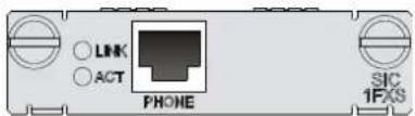
Figure 25 SIC-1FXO panel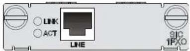
Figure 26 SIC-2FXS panel
Figure 27 SIC-2FXO panel
Table 36 LED description
| LED Description | |
| LINK | Off means the link is idle.On means the link is being occupied for call connection. |
| ACT | Off means the link is idle.On means the link is being occupied for communication. |
Interface cables and connection methods
For more information about FXS/FXO interface cables and connection methods, see "ADSL/BS/FXS/FXO/AM/FCM interface."
SIC-2FXS1FXO
Introduction
The 2-port analog subscriber circuit interface module and 1-port voice AT0 loop trunk interface module (SIC-2FXS1FXO) provide access for and handle three channels of analog voice signals over data communication networks. Two FXS interfaces and one FXO interface are available on a SIC-2FXS1FXO module:
- FXS interfaces are analog subscriber line interfaces that provide ordinary analog telephone and fax access and also can connect AT0 loop trunks of exchanges. • FXO interfaces are loop trunk interfaces that provide access for common subscriber lines.
Interface specifications
Table 37 Interface specifications
| Item | Specification |
| Connector type RJ-11 | |
| Number of connectors | 2 FXS interfaces1 FXO interface |
| Interface standard | Supports subscriber circuit interface (FXS), compliant with ITU Q.512Supports loop trunk interface (FXO), compliant with ITU Q.552Over-current and over-voltage protection compliant with ITU K.20 |
| Cable type Telephone cable | with ferrite core |
| Dial-up mode Supports DTMF, compliant with GB3378, but does not support pulse dial-up. | |
| Bandwidth 300 Hz to 3400 Hz | |
Interface LEDs
Figure 28 SIC-2FXS1FXO panel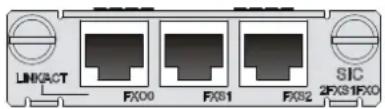
Table 38 LED description
| LED Description | |
| LINK/ACT | Off means the link is idle.On (Green) means the link is being occupied for call connection.Flashing (Yellow) means the link is being occupied for communication. |
Interface cables and connection methods
For more information about FXS/FXO interface cables and connection methods, see "ADSL/BS/FXS/FXO/AM/FCM interface."
DSIC-4FXS1FXO
Introduction
The 4-port analog subscriber circuit interface module and 1-port voice AT0 loop trunk interface module (DSIC-4FXS1FXO) provide access for and handle five channels of analog voice signals over data communication networks.
- FXS interfaces are analog subscriber line interfaces that provide ordinary analog telephone and fax access and also can connect AT0 loop trunks of exchanges; • FXO interfaces are loop trunk interfaces that provide access for common subscriber lines.
Interface specifications
Table 39 Interface specifications
| Item | Specification |
| Connector type RJ-11 | |
| Number of connectors | 4 FXS interfaces1 FXO interface |
| Interface standard | Supports subscriber circuit interface (FXS), compliant with ITU Q.512Supports loop trunk interface (FXO), compliant with ITU Q.552Over-current and over-voltage protection compliant with ITU K.20 |
| Cable type Telephone cable | with ferrite core |
| Dial-up mode Supports DTMF, compliant with GB3378, but does not support pulse dial-up. | |
| Bandwidth 300 Hz to 3400 Hz | |
Interface LEDs
Figure 29 DSIC-4FXS1FXO panel
| DISC4FX01FXD | LINKACTFX00 | FX01 | FX02 | FX03 | LINKACTFX04 | DISC4FX01FXD |
Table 40 LED description
| LED Description | |
| LINK/ACT | Off means the link is idle.On (Green) means the link is being occupied for call connection.Flashing (Yellow) means the link is being occupied for communication. |
Interface cables and connection methods
For more information about FXS/FXO interface cables and connection methods, see "ADSL/BS/FXS/FXO/AM/FCM interface."
SIC-1BSV/SIC-2BSV
Introduction
The 2-port ISDN BRI S/T voice interface module (SIC-2BSV) processes ISDN interface voice traffic. The interfaces on the SIC-2BSV module are ITU-T I.430-compliant. They use pseudo-ternary coding, provide 192 Kbps interface rate, and allow a maximum transmission distance of 1 km (0.6 miles) in
point-to-point mode. In the upstream direction, the SIC-2BSV module can be connected to a user interface on an ISDN switch to receive and decompress, compress and transmit ISDN BRI digital voice traffic. In the downstream direction, the module can be connected to a TE device to forward voice packets from the TE device to the Internet through a WAN interface on the router to implement VoIP. The module provides the following features:
- A BSV interface supports user and network modes for connecting an ISDN network and a TE device, respectively.
- When a BSV interface operates in network mode, traffic is processed as follows:
The digital voice traffic received on the BSV interface is compressed and forwarded through the CPU on the main processing unit (MPU) to a WAN interface. The IP voice traffic received on a WAN interface is forwarded through the CPU on the MPU to SIC-2BSV, where the traffic is decompressed and sent to the TE device.
- When a BSV interface operates in user mode, traffic is processed as follows:
The digital voice traffic received from the B channels on the BSV interface is decompressed and forwarded through the CPU on the MPU to a local FXS or FXO analog voice interface. The voice signals received on the local FXS or FXO analog voice interface are processed by VoIP and forwarded through the CPU on the MPU to the SIC-2BSV. The SIC-2BSV decompresses the traffic and sends the traffic out of the BSV interface to the ISDN switch.
- Working in conjunction with the FXS or FXO analog voice interface modules, SIC-2BSV provides flexibility in voice call routing. • The ISDN BRI D channel signaling is processed separately on the CPU. • A BSV interface can be connected to an ISDN phone to supply power to the phone. • The SIC-2BSV is dedicated to voice applications.
Interface specifications
Table 41 Interface specifications
| Item | Specification |
| Connector | RJ-45 |
| Number of connectors 2 | |
| Interface standard ITU-T I.430, Q.921, Q.931 | |
| Interface rate 192 Kbps | |
| Cable ISDN S interface cable | |
| Supported service Voice access over ISDN S interface cable | |
Interface LEDs
Figure 30 SIC-2BSV panel
Table 42 LED description
| LED | Description |
| B1 Flashing indicates data is being transmitted or received on the B1 channel. | |
| B2 Flashing green indicates data is being transmitted or received on the B2 channel. | |
| ACT | Flashing yellow indicates the link is being activated.Steady green indicates the link is active. |
| On Steady green indicates the module is powered on. | |
Interface cables and connection methods
For more information about BSV interface cables and connection methods, see "BSV/BSE interface."
SIC-1VE1
Introduction
The 1-port E1 voice interface module (SIC-1VE1) handles dense voice signals in a VoIP system. It provides a CE1/PRI/R2 port that can process a maximum of 30 channels of voice signals.
Interface specifications
Table 43 Interface specifications
| Item | Specification |
| Connector | DB 15 |
| Number of connector 1 | |
| Interface standard G.703, G.704 | |
| Interface rate 2.048 Mbps | |
| Frame format | Ethernet_IEthernet_SNAPIEEE 802.2IEEE 802.3 |
| Cable type | 75-ohm unbalanced coaxial cable120-ohm balanced twisted pair cableCoaxial connector, network interface connector and 75-ohm to 120-ohm adapter (with BNC connector) |
| Operating mode | CE1ISDN PRI (only supported by SIC-1VE1)R2 |
| Services | BackupTerminal accessISDN (only supported by SIC-1VE1) |
Interface LEDs
Figure 31 SIC-1VE1 panel
Table 44 LED description
| LED | Description |
| LINK/ACT | On means carrier signal has been received.Flashing means data is being transmitted or received.Off means no carrier signal has been received. |
| LP/AL | On means the interface is in a loopback.Flashing means an AIS, LFA, or RAI alarm signal is present.Off means neither loopback nor alarm is present. |
| Note:AIS = Alarm indication signal; LFA = loss of frame alignment; RAI = Remote alarm indication | |
Interface cables and connection methods
For more information about E1 interface cables, see "E1 interface."
SIC-1VT1
Introduction
The 1-port T1 voice interface module (SIC-1VT1) handles dense voice signals in a VoIP system. It provides a CT1/PRI/R2 port that can process a maximum of 23 channels of voice signals.
Interface specifications
Table 45 Interface specifications
| Item | Specification |
| Connector | RJ-45 |
| Number of connector 1 | |
| Interface standard | G.703/T1.102G.704AT&T TR 54016AT&T TR 62411ANSI T1.403 |
| Interface rate 1.544 Mbps | |
| Cable type T1 cable (100-ohm standard shielded cable) | |
| Operating mode | CT1ISDN PRI |
| Services | BackupTerminal accessISDN |
Interface LEDs
Figure 32 SIC-1VT1 panel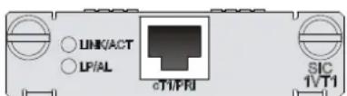
Table 46 LED description
| LED | Description |
| LINK/ACT | On means carrier signal has been received.Flashing means data is being transmitted or received.Off means no carrier signal has been received. |
| LP/AL | On means the interface is in a loopback.Flashing means an AIS, LFA, or RAI alarm signal is present.Off means neither loopback nor alarm is present. |
| Note:AIS = Alarm indication signal; LFA = loss of frame alignment; RAI = Remote alarm indication | |
Interface cables and connection methods
For more information about T1 interface cables and connection methods, see "T1 interface."
SIC-1VE1T1
Introduction
The 1-port E1/T1 voice interface module (SIC-1VE1T1) handles dense voice signals in VoIP and FoIP systems. The E1 module transmits, receives, and processes E1 voice signals. It allows the interface to operate in CE1 mode or ISDN PRI mode to process a maximum of 30 channels of voice signals. The T1 module transmits, receives, and processes T1 voice signals. It allows the interface to operate in CT1 mode or ISDN PRI mode to process a maximum of 23 channels of voice signals.
Interface specifications
Table 47 Interface specifications
| Item | Specification |
| Connector | RJ-45 |
| Number of connector 1 | |
| Interface standard | G.703G.704 |
| Interface rate | E1 interface: 2.048MbpsT1 interface: 1.544 Mbps |
| Cable type | E1 75-ohm coaxial cableE1 120-ohm twisted pair cable: 2 m (6.56 ft), 15 m (49.21 ft), or 30 m (98.43 ft)T1 100-ohm standard shielded cableCoaxial connector, network interface connector, or 75-to-120-ohm adapter (with BNC connector) |
| Operating mode | E1T1CE1T1ISDN PRI |
| Services | BackupTerminal accessISDN PRI |
Interface LEDs
Figure 33 SIC-1VT1 panel
Table 48 LED description
| LED | Description |
| LINK/ACT | Steady green means that carrier signal has been received.Flashing green at 4 Hz means that data is being transmitted or received.Off means that no carrier signals have been received. |
| LP/AL | Steady yellow means that the interface is in loopback mode.Flashing yellow at 0.5 Hz means that an AIS, LFA, or RAI alarm is present.Off means that neither loopback nor alarm is present. |
Interface cables and connection methods
For more information about E1 interface cables and connection methods, see "E1 interface."
For more information about T1 interface cables and connection methods, see "T1 interface."
RT-SIC-1VE1T1
Introduction
The 1-port E1/T1 voice interface module RT-SIC-1VE1T1 handles dense voice signals in VoIP and FoIP systems. The E1 module transmits, receives, and processes E1 voice signals. It allows the interface to operate in CE1 mode or ISDN PRI mode to process a maximum of 30 channels of voice signals. The T1 module transmits, receives, and processes T1 voice signals. It allows the interface to operate in CT1 mode or ISDN PRI mode to process a maximum of 23 channels of voice signals.
You can use command lines and a jumper to configure the interface as a 75-ohm E1 interface, 100-ohm T1 interface, or 120-ohm E1 interface. By default, the interface is a 75-ohm E1 interface.
- To configure the interface as a 75-ohm E1 interface, connect the jumper to pins 1 and 2, pins 7 and 8, pins 11 and 12, and pins 13 and 14.
- To configure the interface as a 100-ohm T1 or 120-ohm E1 interface, connect the jumper to pins 1 to 3, pins 5 to 7, pins 9 and 10, and pins 11 to 13.
Figure 34 Jumper connecting methods
Interface specifications
Table 49 Interface specifications
| Item | Specification |
| Connector | RJ-45 |
| Number of connector 1 | |
| Interface standard | G.703G.704 |
| Interface rate | E1 interface: 2.048MbpsT1 interface: 1.544 Mbps |
| Cable type | E1 75-ohm coaxial cableE1 120-ohm twisted pair cable: 2 m (6.56 ft), 15 m (49.21 ft), or 30 m (98.43 ft)T1 100-ohm standard shielded cableCoaxial connector, network interface connector, or 75-to-120-ohm adapter (with BNC connector) |
| Operating mode | E1T1CE1T1ISDN PRI |
| Services | BackupTerminal accessISDN PRI |
Interface LEDs
Figure 35 RT-SIC-1VE1T1 panel
Table 50 LED description
| LED | Description |
| LINK/ACT | Steady green: Carrier signal has been received.Flashing green at 4 Hz: Data is being transmitted or received.Off: No carrier signals have been received. |
| LP/AL | Steady yellow: The interface is in loopback mode.Flashing yellow at 0.5 Hz: An AIS, LFA, or RAI alarm is present.Off: Neither loopback nor alarm is present. |
Interface cables and connection methods
For more information about E1 interface cables and connection methods, see "E1 interface."
For more information about T1 interface cables and connection methods, see "T1 interface."
WLAN interface module
- SIC-WLAN-b/g/n • SIC-WLAN-b/g/n(NA)
SIC-WLAN-b/g/n/SIC-WLAN-b/g/n(NA)
Introduction
The SIC-WLAN-b/g/n module receives and sends 802.11b/g/n WIFI protocol data. Two external omnidirectional antennas are available on the module. The antennas follow the 802.11b/g/n standard, work on the 2.4 GHz channel and support 2*2 radio MIMO.
The SIC-WLAN-b/g/n (NA) modules are applicable only in North America, and the area code is fixed at NA. The other specifications for the SIC-WLAN-b/g/n (NA) modules are the same as the SIC-WLAN-b/g/n modules.
Interface specifications
Table 51 Interface specifications
| Item | Specification |
| Interface standard | Supports 802.11b/g/n standard.Works at the 2.4 G band. |
| Rate | 54 Mbps300 Mbps (40 MHz)130 Mbps(20 MHz) |
| Operating mode CCK+ OFDM + 2*2 Radio MIMO | |
| Services | WLAN Layer 2/Layer 3 accessWLAN encryptionWLAN security |
Interface LEDs
Figure 36 SIC-WLAN-b/g/n panel
Table 52 LED description
| LED Description | |
| LINK/ACT | Off means the link is idle.Steady green means a link is present and a call connection is being established.Flashing yellow means a link is present and there is a call activity. |
Interface cables and connection methods
For more information about WLAN interface cables and connection methods, see "WLAN interface."
3G interface module
- SIC-3G-GSM
- SIC-3G-HSPA
- SIC-3G-HSPA+
SIC-3G-GSM
Introduction
The SIC-3G-GSM module provides access to 3G networks. It supports the following features:
• General Packet Radio Service (GPRS) • Enhanced Data Rate for GSM Evolution (EDGE) • Universal Mobile Telecommunications System (UMTS) • High Speed Downlink Packet Access (HSDPA)
Interface specifications
Table 53 Interface specifications
| Item | Specification |
| Connector type | TNC: For connecting an antenna and accessing WLANs.RJ-45: For connecting to a third-party WLAN debugging and testing software such as CAIT of Qualcomm. |
| Number of connectors | 1 TNC RF1 RJ-45 |
| Interface standard | TNC RF: Omni antenna, supporting GPRS/EDGE/UMTS/HSDPA.RJ-45: RS232 |
| Cable type | TNC RF: NoneRJ-45: AUX cable |
| Rates | HSDPA (downlink: 7.2 Mbps)HSUPA (uplink: 5.76 Mbps)UMTS (downlink: 384 Mbps, uplink: 384 Kbps)EDGE (downlink: 236.8 Kbps, uplink: 236.8 Kbps)GPRS (downlink: 85.6 Kbps, uplink: 85.6 Kbps) |
| Services | GPRS/EDGE/UMTS/HSDPA |
Interface LEDs
Figure 37 SIC-3G-GSM panel
Table 54 LED description
| LED Description | |
| WWAN | Steady green means that a link is present.Flashing green means that data is being transmitted or received. |
| RSSI | Steady green means strong signal.Flashing green means middle or low signal.Off means weak signal or no signal. |
| UMTS | Steady yellow means the service is valid.Off means no service. |
| HSDPA | Steady yellow means the service is valid.Off means no service. |
Antenna, interface cable, and the connection method
For more information about SIC-3G-GSM interface cables and connection methods, see "WLAN interface."
Installing a SIM card
- Push the 3G SIM card holder in the direction marked "OPEN" so the holder projects upwards. Do not insert the 3G SIM card to the card holder before projecting the card holder up. Do not forcibly lift the holder.
- Insert the 3G SIM card along the slide rails to the holder.
- Put down the holder and push the holder in the direction marked "LOCK" to lock the card in position.
- Position the 3G SIM card socket cover and fasten the screws on the cover.
- Execute the display cellular [slot]/0 all command after the router is started. When "SIM Status = OK" appears in the output information, the SIM card is identified.
SIC-3G-HSPA
Introduction
The SIC-3G-HSPA module provides access to 3G networks. It provides the following features:
• GPRS - EDGE - UMTS • HSDPA
Interface specifications
Table 55 Interface specifications
| Item | Specification |
| Connector type | TNC: For connecting an antenna and accessing WLANs.RJ-45: For connecting to a third-party WLAN debugging and testing software such as CAIT of Qualcomm. |
| Number of connectors | 2 TNC RF1 RJ-45 |
| Interface standard | TNC RF: Omni antenna, supporting GPRS/EDGE/UMTS/HSDPA.RJ-45: RS232 |
| Cable type | TNC RF: NoneRJ-45: AUX cable |
| Rates | HSDPA (downlink: 7.2 Mbps)HSUPA (uplink: 5.76 Mbps)UMTS (downlink: 384 Mbps, uplink: 384 Kbps)EDGE (downlink: 236.8 Kbps, uplink: 236.8 Kbps)GPRS (downlink: 85.6 Kbps, uplink: 85.6 Kbps) |
| Services | GPRS/EDGE/UMTS/HSDPA |
| Supported wireless band | 850/900/1900/2100MHz WCDMA/HSDPA/HSUPA850/900/1800/1900MHz GPRS/EDGE |
Interface LEDs
Figure 38 SIC-3G-HSPA panel
Table 56 LED description
| LED Description | |
| WWAN | Steady green means that a link is present.Flashing green means that data is being transmitted or received. |
| RSSI | Steady green means strong signal.Flashing green means middle or low signal.Off means weak signal or no signal. |
| UMTS | Steady yellow means the service is valid.Off means no service. |
| HSDPA | Steady yellow means the service is valid.Off means no service. |
Antenna, interface cables, and connection methods
CAUTION:
The 3G antenna provided with the SIC-3G-HSPA must be installed on the antenna port that has a MAIN mark.
For more information about SIC-3G-HSPA Interface cables and connection methods, see "WLAN interface."
Installing a SIM card
- Push the 3G SIM card holder in the direction marked "OPEN" so the holder projects upwards. Do not insert the 3G SIM card into the card holder before projecting the card holder up. Do not forcibly lift the holder.
- Insert the 3G SIM card along the slide rails into the holder.
- Put down the holder and push it in the direction marked "LOCK" to lock the card in position.
- Position the 3G SIM card socket cover and fasten the screws on the cover.
- Execute the display cellular [slot]/0 all command after the router is started. When "SIM Status = OK" appears in the output information, the SIM card is identified.
SIC-3G-HSPA+
Introduction
The SIC-3G-HSPA+ module provides access to 3G networks. It provides the following features:
• GPRS - EDGE - UMTS • HSDPA
Interface specifications
Table 57 Interface specifications
| Item | Specification |
| Connector type | TNC: For connecting an antenna and accessing WLANs.RJ-45: For connecting to a third-party WLAN debugging and testing software such as CAIT of Qualcomm. |
| Number of connectors | 2 TNC RF1 RJ-45 |
| Interface standard | TNC RF: Omni antenna, supporting GPRS/EDGE/UMTS/HSDPA.RJ-45: RS232 |
| Cable type | TNC RF: NoneRJ-45: AUX cable |
| Rates | HSDPA (downlink: 7.2 Mbps)HSUPA (uplink: 5.76 Mbps)UMTS (downlink: 384 Mbps, uplink: 384 Kbps)EDGE (downlink: 236.8 Kbps, uplink: 236.8 Kbps)GPRS (downlink: 85.6 Kbps, uplink: 85.6 Kbps) |
| Services | GPRS/EDGE/UMTS/HSDPA |
| Supported wireless band | 850/900/1900/2100MHz WCDMA/HSDPA/HSUPA850/900/1800/1900MHz GPRS/EDGE |
Interface LEDs
Figure 39 SIC-3G-HSPA+ panel
Table 58 LED description
| LED Description | |
| WWAN | Steady green means that a link is present.Flashing green means that data is being transmitted or received. |
| RSSI | Steady green means strong signal.Flashing green means middle or low signal.Off means weak signal or no signal. |
| UMTS | Steady yellow means the service is valid.Off means no service. |
| HSDPA | Steady yellow means the service is valid.Off means no service. |
Antenna, interface cables, and connection methods

CAUTION:
The 3G antenna provided with the SIC-3G-HSPA+ must be installed on the antenna port that has a MAIN mark.
For more information about SIC-3G-HSPA+ interface cables and connection methods, see "WLAN interface."
Installing a SIM card
- Push the 3G SIM card holder in the direction marked "OPEN" so the holder projects upwards. Do not insert the 3G SIM card into the card holder before projecting the card holder up. Do not forcibly lift the holder.
- Insert the 3G SIM card along the slide rails into the holder.
- Put down the holder and push it in the direction marked "LOCK" to lock the card in position.
- Position the 3G SIM card socket cover and fasten the screws on the cover.
- Execute the display cellular [slot]/0 all command after the router is started. When "SIM Status = OK" appears in the output information, the SIM card is identified.
4G interface module
- SIC-4G-LTE-V
- SIC-4G-LTE-A
- SIC-4G-LTE-G
SIC-4G-LTE-V
The SIC-4G-LTE-V module provides access to 4G WLANs. It provides the following features:
- UMTS
- HSPA+
- CDMA 1x
- EV-DO Rev A
- Quad-Band EDGE • GPRS
- GSM
- Long Term Evolution (LTE)
Interface specifications
Table 59 Interface specifications
| Item | Specification |
| Connector type | TNC: For accessing WLANs.SMA: For accessing GPS.Mini USB Type AB: For connecting to third-party WLAN debugging and testing software such as CAIT of Qualcomm. |
| Number of connectors | 2 TNCs1 SMA1 Mini USB Type AB |
| Interface standard | TNC: Supports LTE, UMTS, HSPA+, CDMA 1x, EV-DO Rev A, Quad-Band EDGE, GPRS, and GSMSMA: GPSMini USB Type AB: RS232 |
| Cable type | SMA: Flexible 174 sized cableTNC: NoneMini USB Type AB: USB console cable |
| Services | LTEUMTSHSPA+CDMA 1xEV-DO Rev AQuad-Band EDGEGPRSGSM |
Interface LEDs
Figure 40 SIC-4G-LTE-V panel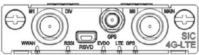
Table 60 LED description
| LED | Description |
| WWAN | Steady green indicates that a link is present.Flashing green indicates that data is being transmitted or received. |
| RSSI | Steady green indicates strong signal.Flashing green indicates middle or low signal.Off indicates weak signal or no signal. |
| EVDO | Steady green means the HSDPA service is valid.Flashing green means the EVDO service is valid.Off means no service. |
| LTE | Steady yellow means the service is valid.Off means no service. |
| GPS | Steady yellow means the service is valid.Off means no service. |
Connecting the antenna and interface cable
For more information, see "4G interface."
Installing a SIM card
- Push the 3G SIM card holder in the direction marked "OPEN" so the holder projects upwards. Do not insert the 3G SIM card into the card holder before projecting the card holder up. Do not forcibly lift the holder.
- Insert the 3G SIM card along the slide rails into the holder.
- Put down the holder and push it in the direction marked "LOCK" to lock the card in position.
- Position the 3G SIM card socket cover and fasten the screws on the cover.
- Execute the display cellular [slot]/0 all command after the router is started. When "SIM Status = OK" appears in the output information, the SIM module is identified.
SIC-4G-LTE-A/SIC-4G-LTE-G
The SIC-4G-LTE-A and SIC-4G-LTE-G are similar in appearance. The SIC-4G-LTE-A/SIC-4G-LTE-G module provides access to 4G networks. It supports the following features:
• LTE • UMTS - HSPA+ - Quad-Band EDGE
• GPRS • GSM
Interface specifications
Table 61 Interface specifications
| Item | Specification |
| Connector type | TNC: Antenna for accessing WLANs.SMA: For accessing GPS.Mini USB Type AB: For connecting to a third-party WLAN debugging and testing software such as CAIT of Qualcomm. |
| Number of connectors | 2 TNCs1 SMA1 Mini USB Type AB |
| Interface standard | TNC: Supports LTE, UMTS, HSPA+, CDMA 1x, EV-DO Rev A, Quad-Band EDGE, GPRS, and GSM.SMA: GPS.Mini USB Type AB: RS232. |
| Cable type | SMA: Flexible 174 sized cable.TNC: None.Mini USB Type AB: USB console cable. |
| Services | LTEUMTSHSPA+Quad-Band EDGEGPRSGSM |
Interface LEDs
Figure 41 SIC-4G-LTE-A/SIC-4G-LTE-G panel
Table 62 LED description
| LED Description | |
| WWAN | Steady green means that a link is present.Flashing green means that data is being transmitted or received. |
| RSSI | Steady green means strong signal.Flashing green means middle or low signal.Off means weak signal or no signal. |
| HSPA+ | Steady yellow means the service is valid.Off means no service. |
| LTE | Steady yellow means the service is valid.Off means no service. |
| GPS | Steady yellow means the service is valid.Off means no service. |
Connecting the antenna and interface cables
For more information, see "4G interface."
Installing a SIM card
- Push the 3G SIM card holder in the direction marked "OPEN" so the holder projects upwards. Do not insert the 3G SIM card into the card holder before projecting the card holder up. Do not forcibly lift the holder.
- Insert the 3G SIM card along the slide rails into the holder.
- Put down the holder and push the holder in the direction marked "LOCK" to lock the card in position.
- Position the 3G SIM card socket cover and fasten the screws on the cover.
- Execute the display cellular [slot]/0 all command after the router is started. When "SIM Status = OK" appears in the output information, the SIM card is identified.
MIM/DMIM/XMIM
The MSR series routers provide a wide range of optional MIM/DMIMs. The MIM/DMIMs provide interfaces such as synchronous/asynchronous serial interface, Ethernet interface, E1/T1, ISDN BRI/PRI, audio interface, and Layer 2 switching interface.
The MIM-16FSW and the DMIM-24FSW support PoE to provide -48 VDC power to remote PDs such as IP phone, AP, and network camera through straight-through network cables when installed in a PoE router.
Ethernet switching module
- MIM-16FSW
- MIM-16FSW-PoE
- DMIM-24FSW
- DMIM-24FSW-PoE
- XMIM-16FSW
- XMIM-24FSW
XMIM-16FSW/XMIM-24FSW
Introduction
The 16/24-port 10/100 Mbps Ethernet Layer 2 switching MIM interface modules (XMIM-16FSW and XMIM-24FSW) can be installed on the MSR30-11. Both the XMIM-16FSW and XMIM-24FSW are suitable for a small enterprise network to act as a switching & routing device, which can be directly connected to PCs and network devices of the enterprise.
Interface specifications
Table 63 Interface specifications
| Item | Specification |
| Connector type RJ-45 | |
| Interface type MDI/MDIX | |
| Number of connectors | 16/24 x 100 Mbps RJ-45 connector |
| Transmission distance | 100 m (328.08 ft) over category-5 twisted pair cables (both crossover and straight-through) |
| Operating mode 10/100 Mbps auto-sensing, full duplex/half duplex | |
Interface LEDs
Figure 42 XMIM-16FSW panel
Figure 43 XMIM-24FSW panel
Each 10/100 Mbps Ethernet interface on the panel has two LEDs.
Table 64 LED description
| LED status Description | |
| Green LED (LINK) | On: A link is present.Off: No link is present. |
| Yellow LED (ACT) | Flashing: Data is being received and sent on the port.Off: No data is being received or sent on the port. |
Interface cables and connection methods
For more information about the Ethernet interface cables and connection methods, see "Ethernet interface."
MIM-16FSW/MIM-16FSW-PoE/DMIM-24FSW/DMIM-24FSW-PoE
Introduction
The 16/24-port 10/100 Mbps Ethernet Layer 2 switching MIM interface modules (MIM-16FSW/MIM-16FSW-PoE and DMIM-24FSW/DMIM-24FSW-PoE) are applicable to MSR30 series routers. A router installed with MIM-16FSW or DMIM-24FSW can work as a switching and routing integrated device on a small-sized enterprise network to connect PCs and network devices inside the network. The MIM-16FSW-PoE/DMIM-24FSW-PoE can supply power to PDs through PoE.
Interface specifications
Table 65 Interface specifications
| Item | MIM-16FSW/MIM-16FSW-PoE | DMIM-24FSW/DMIM-24FSW-PoE |
| Connector RJ-45 RJ-45 + SFP fiber port | ||
| Interface type MDI/MDIX MDI/MDIX + SFP fiber port | ||
| Number of connectors | 16 x 100 Mbps RJ-45 connectors | 24 x 100 Mbps RJ-45 connectorsTwo 1000 Mbps RJ-45 connectorsTwo SFP connectors |
| Transmission distance | 100 m (328.08 ft) over category-5 twisted pair cables (both crossover and straight-through) | 100 m (328.08 ft) over category-5 twisted pair cables (both crossover and straight-through)Fiber interface supports SFP fiber module |
| Operating mode | 10/100 Mbps autosensing, full/half duplex | 24 x 100 Mbps copper port: 10/100 Mbps autosensing2 x GE copper port: 10/100/1000 Mbps autosensing2 x GE fiber port: GE SFP fiber port |
Interface LEDs
Figure 44 MIM-16FSW panel
Figure 45 MIM-16FSW-PoE panel
Figure 46 DMIM-24FSW panel
Figure 47 DMIM-24FSW-PoE panel
Table 66 Description for the MIM-16FSW/MIM-16FSW-PoE/DMIM-24FSW/DMIM-24FSW-PoE FE LEDs
| LED status Description |
| Steady green A link is present, but no data is being transmitted and received. |
| Off No link is present. |
| Flashing green A link is present and data is being transmitted and received (ACT). |
Table 67 Description for the DMIM-24FSW/DMIM-24FSW-PoE GE interface LEDs
| LED status Description | |
| Off No link is present. | |
| Steady green A gigabit link is present, but no data is being transmitted and received. | |
| Flashing green A gigabit link is present and data is being transmitted and received (ACT). | |
| Steady yellow A 100 Mbps link is present, but no data is being transmitted and received. | |
| Flashing yellow | A 100 Mbps link is present and data is being transmitted and received (ACT). |
Table 68 Description for the DMIM-24FSW/DMIM-24FSW-PoE fiber interface LEDs
| LED status Description | |
| Off No link is present. | |
| Steady green A link is present, but no data is being transmitted and received. | |
| Flashing green A link is present and data is being transmitted and received (ACT). | |
| Steady yellow Error prompt | |
NOTE:
The two GE interfaces on the DMIM-24FSW-PoE do not support PoE.
Interface cables and connection methods
For more information about the Ethernet interface cables and connection methods, see "Ethernet interface."
For more information about fiber ports, optical fibers, and the connection methods, see "Fiber port."
Ethernet interface module
- MIM-2FE
- MIM-4FE
- MIM-2GBE
MIM-2FE/MIM-4FE
Introduction
The 2/4-port 10/100Base-TX Fast Ethernet interface module (MIM-2FE/MIM-4FE) completes communications between routers and LANs.
Interface specifications
Table 69 Interface specifications
| Item | Specification | |
| MIM-2FE | MIM-4FE | |
| Connector | RJ-45 | |
| Type of interface MDI | ||
| Number of connectors 2 4 | ||
| Transmission distance | 100 m (328.08 ft) over category-5 twisted pair cables (both crossover and straight-through) | |
| Operating mode 10/100 Mbps autosensing, full duplex/ half-duplex | ||
Interface LEDs
Figure 48 MIM-2FE panel
Figure 49 MIM-4FE panel
Table 70 LED description
| LED Description | |
| LINK | Off means the Ethernet link is not connected.On means the link is connected. |
| ACTIVE | Off means no data is being transmitted or received;Flashing means data is being received or/and transmitted. |
Interface cables and connection methods
For more information about the Ethernet interface cables and connection methods, see "Ethernet interface."
MIM-2GBE
Introduction
The 2-port 10Base-T/100Base-TX/1000Base-T Ethernet electrical interface module completes the communication between a router and a LAN.
Interface specifications
Table 71 Interface specifications
| Item | Specification |
| Connector | RJ-45 |
| Number of connectors 2 | |
| Interface type MDI/MDIX | |
| Interface standard 802.3, 802.3u, 802.3ab | |
| Transmission distance | 100 m (328.08 ft) over category-5 twisted pair cables (both crossover and straight-through) |
| Operating mode | 10/100/1000 Mbps auto-sensing, half/full duplex |
Interface LEDs
Figure 50 MIM-2GBE
Table 72 LED description
| LED | Description |
| LINK | Off means no link is present;On means a link is present. |
| ACT | Off means no data is being transmitted or received;Flashing means data is being received or/and transmitted. |
Interface cables and connection methods
For more information about the Ethernet interface cables and connection methods, see "Ethernet interface."
ATM interface module
- MIM-1ATM-OC3
- MIM-IMA-8E1
- MIM-IMA-4T1
MIM-1ATM-OC3
Introduction
The 1-port ATM (Asynchronous Transfer Mode) 155 Mbps optical interface module (MIM-1ATM-OC3) provides ATM interfaces for routers. It provides the following features:
- Two frame formats: SDH STM-1 and SONET OC-3;
- Scrambling in data transmission;
- Both line clock (when working as DTE interface), and internal clock (when working as DCE interface);
- Three types of test measures: local cell loopback, local payload loopback, and remote loopback.
Interface specifications
Table 73 Interface specifications
| Item | Specification |
| Number of interfaces 1 | |
| Connector | SFP/LC |
| Interface standard SONET OC-3/SDH STM-1 | |
| Operating mode 1000 Mbps, full duplex | |
Interface LEDs
Figure 51 MIM-1ATM-OC3 panel
Table 74 LED description
| LED | Description |
| LINK/ACT | On means carrier signal has been received.Flashing means data is being received or/and transmitted.Off means no carrier signal has been received. |
| LP/AL | On means the interface is in a loopback.Flashing means an AIS, LFA, or RAI alarm signal is present.Off means no loopback or alarm is present. |
| Note:LFA = Loss of frame alignment; AIS = Alarm indication signal; RAI = Remote alarm indication. | |
Fiber ports, optical fibers, and the connection method
For more information about fiber ports, optical fibers, and the connection methods, see "Fiber port."
MIM-IMA-8E1
Introduction
The 8-port E1 ATM inverse multiplexing interface module (MIM-IMA-8E1) provides four/eight E1 interfaces that support the IMA (inverse multiplexing for ATM) technology.
The IMA technology combines multiple low-speed links into a group to support a high-speed ATM cell stream. It distributes an ATM cell stream over multiple low-speed E1 links on a cell-by-cell basis at the transmission end and reassembles the cells on the low-speed E1 links into the original stream at the far end. This technology provides a scalable and cost-effective solution, and is commonly used in plesiochronous digital hierarchy (PDH) networks to transport ATM cells.
Interface specifications
Table 75 Interface specifications
| Item | Specification |
| Connector | DB68 |
| Number of connectors | 1 |
| Interface standard | ITU-G.703, ITU-G.704 |
| Interface rate 2.048 Mbps | |
| Cable type 75-ohm 8E1 conversion cable | |
| Max transmission distance | 500 m (1640.4 ft) |
| Operating mode ATM E1 independent link/IMA bundle mode | |
| Supported service | AAL5 (ATM adaptation layer 5) |
| Protocol PPPoA, PPPoEoA, IPoA, IPoEoA | |
| Service type CBR/VBR-rt/VBR-nrt/UBR | |
Interface LEDs
Figure 52 MIM-IMA-8E1 (75-ohm) panel
Table 76 LED description
| LED | Description |
| LINK/ACT | On means carrier signal has been received.Flashing means data is being received or/and transmitted.Off means no carrier signal has been received. |
| LP/AL | On means the interface is in a loopback.Flashing means an AIS, LFA, or RAI alarm signal is present.Off means no loopback or alarm is present. |
| Note:AIS = Alarm indication signal; LFA = loss of frame alignment; RAI = Remote alarm indication | |
Interface cables and connection methods
For more information about E1 interface cables, see "E1 interface."
MIM-IMA-4T1
Introduction
The 4-port ATM inverse multiplexing interface module (MIM-IMA-4T1) provides four/eight T1 interfaces that support the IMA technology. Their network application is similar to the MIM-IMA-4E1/MIM-IMA-8E1 module.
Interface specifications
Table 77 Interface specifications
| Item | Specification |
| Connector | DB68 |
| Number of connectors 1 | |
| Interface standard ITU-G.703, ITU-G.704 | |
| Cable type 4T1 conversion cable (100-ohm straight-through shielded) | |
| Max transmission distance 150 m (492.1 ft) | |
| Operating mode ATM T1 independent link/IMA bundle mode | |
| Supported service AAL5 | |
| Protocol PPPoA, PPPoEoA, IPoA, IPoEoA | |
| Transmission rate CBR/VBR-rt/VBR-nrt/UBR |
Interface LEDs
Figure 53 MIM-IMA-4T1 panel
Table 78 LED description
| LED | Description |
| LINK/ACT | On means carrier signal has been received.Flashing means data is being received or/and transmitted.Off means no carrier signal has been received. |
| LP/AL | On means the interface is in a loopback.Flashing means an AIS, LFA, or RAI alarm signal is present.Off means no loopback or alarm is present. |
| Note:AIS = Alarm indication signal; LFA = loss of frame alignment; RAI = Remote alarm indication | |
Interface cables and connection methods
For more information about T1 interface cables and connection methods, see "T1 interface."
POS (SDH/SONET) interface module
- MIM-1POS
MIM-1POS
Introduction
The 1-port SDH/SONET interface module (MIM-1POS) provides interface rates up to 155.52 Mbps (STM-1/OC-3).
The MIM-1POS can use the protocols such as PPP, Frame Relay, and HDLC at the data link layer and IP at the network layer. It allows direct transmission of packets over SONET/SDH.
Interface specifications
Table 79 Interface specifications
| Item | Specification |
| Connector | SFP/LC |
| Interface standard | SONET OC-3/SDH STM-1 |
| Number of interfaces | 1 |
| Interface rate | 155.52 Mbps |
Interface LEDs
Figure 54 MIM-1POS panel
Table 80 LED description
| LED | Description |
| LINK/ACT | On means carrier signal has been received.Flashing means data is being received or/and transmitted.Off means no carrier signal has been received. |
| LP/AL | On means the interface is in a loopback.Flashing means an AIS, LFA, or RAI alarm signal is present.Off means no loopback or alarm is present. |
| Note:AIS = Alarm indication signal; LFA = loss of frame alignment; RAI = Remote alarm indication | |
Fiber ports, optical fibers, and the connection methods
For more information about fiber ports, optical fibers, and the connection methods, see "Fiber port."
E1/T1 interface module
- MIM-2E1
- MIM-4E1
- MIM-4E1-F
- MIM-8E1
- MIM-8E1-F
- MIM-2T1
- MIM-4T1-F
- MIM-8T1
- MIM-8T1-F
MIM-2E1/MIM-4E1/MIM-4E1-F modules
Introduction
• MIM-2E1/MIM-4E1
The 2-/4-port channelized E1/PRI interface module (MIM-2E1/MIM-4E1) transmits, receives, and processes E1 data traffic. In addition, you can use the module for other purposes, such as CE1 access and the ISDN PRI function.
- MIM-4E1-F
The MIM-4E1-F module differs from the MIM-2E1/MIM-4E1 module in the following ways:
The FE1 operating mode supported by the E1-F modules allows only one n x 64 kbps bundle to be formed on each interface, where n = 1 to 31. However, an E1 module allows arbitrary grouping of 31 channels and multiple bundles. - The E1-F modules do not support PRI mode.
Interface specifications
Table 81 Interface specifications
| Item | Specification | |
| MIM-2E1 | MIM-4E1/4E1-F | |
| Connector | D15 D25 | |
| Number of connectors 2 1 | ||
| Interface standard G.703, G.704 | ||
| Interface rate 2.048 Mbps | ||
| Cable type | E1 75-ohm unbalanced coaxial cableE1 120-ohm balanced twisted pair cable120-ohm 4E1 conversion cable (MIM-4E1/MIM-4E1-F modules)75-ohm 4E1 conversion cable (MIM-4E1/MIM-4E1-F modules)Coaxial connector, network interface connector and 75-ohm to 120-ohm adapter (with BNC connector) | |
| Operating mode | E1, CE1, ISDN PRI (only supported by MIM-2E1/MIM-4E1)FE1 (only supported by MIM-4E1-F) | |
| Supported service | BackupTerminal access serviceISDN PRI (only supported by MIM-4E1) | |
Interface LEDs
Figure 55 MIM-2E1 panel
Figure 56 MIM-4E1 panel
Figure 57 MIM-4E1-F panel
Table 82 LED description
| LED | Description |
| LINK/ACT | On means carrier signal has been received.Flashing means data is being received or/and transmitted.Off means no carrier signal has been received. |
| LP/AL | On means the interface is in a loopback.Flashing means an AIS, LFA, or RAI alarm signal is present.Off means no loopback or alarm is present. |
| Note:AIS = Alarm indication signal; LFA = loss of frame alignment; RAI = Remote alarm indication | |
Interface cables and connection methods
For more information about E1 interface cables, see "E1 interface."
MIM-8E1/MIM-8E1-F
Introduction
- MIM-8E1 module
The 8-port channelized E1/PRI interface module (MIM-8E1) transmits, receives, and processes eight channels of E1 data traffic. In addition, you can use the module for other purposes, such as CE1 access and the ISDN PRI function.
- MIM-8E1-F module
The 8-port fractional E1 interface module (MIM-8E1-F) differs from the MIM-8E1 module in the following ways:
The FE1 operating mode supported by the MIM-8E1-F module allows only one n x 64 kbps bundle to be formed on each interface, where n = 1 to 31. However, an MIM-8E1 module allows arbitrary grouping of 31 channels and therefore multiple bundles.
- The MIM-8E1-F module does not support PRI mode.
NOTE:
For a MIM-8E1 module, the system automatically creates a serial interface for each timeslot bundle formed on a controller E1 interface.
Interface specifications
Table 83 Interface specifications
| Item | Specification |
| Connector | D68 |
| Number of connectors | 1 |
| Interface standard G.703 | |
| Interface rate 2.048 Mbps | |
| Cable type 75-ohm 8E1 | conversion cable |
| Cable characteristic impedance | 75-ohm |
| Operating mode | E1, CE1, ISDN PRI (only supported by MIM-8E1)FE1 (only supported by MIM-8E1-F) |
| Supported service | BackupTerminal access serviceISDN PRI (only supported by MIM-8E1) |
Interface LEDs
Figure 58 MIM-8E1 (75-ohm) panel
Figure 59 MIM-8E1-F (75-ohm) panel
Table 84 LED description
| LED | Description |
| LINK/ACT | On means carrier signal has been received.Flashing means data is being received or/and transmitted.Off means no carrier signal has been received. |
| LP/AL | On means the interface is in a loopback.Flashing means an AIS, LFA, or RAI alarm signal is present.Off means no loopback or alarm is present. |
| Note:AIS = Alarm indication signal; LFA = loss of frame alignment; RAI = Remote alarm indication | |
Interface cables and connection methods
For more information about E1 interface cables, see "E1 interface."
MIM-2T1/MIM-4T1-F
Introduction
- MIM-2T1
The 2-port channelized T1/PRI interface module (MIM-2T1) transmits, receives, and handles T1 data streams, provides CT1 access, and fulfills the function of ISDN PRI.
- MIM-4T1-F
The 4-port fractional T1 interface module (MIM-4T1-F) and MIM-2T1 module differ in the following ways:
- FT1 operating mode supported by T1-F modules allows only one bundle. The time slots can only be bundled into one n x 64 kbps or 56 kbps channel, where n=1-24. However, a CT1 module allows arbitrary grouping of the 24 channels;
- T1-F does not support PRI mode.
NOTE:
For a T1 module, the system automatically creates a serial interface for each timeslot bundle formed on a controller T1 interface.
Interface specifications
Table 85 Interface specifications
| Item | Specification |
| Connector | RJ-45 |
| Number of connectors | 2 (MIM-2T1 module)4 (MIM-4T1-F module) |
| Interface standard | G.703/T1.102G.704AT&T TR 54016AT&T TR 62411ANSI T1.403 |
| Interface rate 1.544 Mbps | |
| Cable type T1 cable (100-ohm shielding network cable) | |
| Operating mode | CT1, ISDN PRI (MIM-2T1 module)FT1 (MIM-4T1-F module) |
| Supported service | BackupTerminal access serviceISDN PRI (MIM-2T1 module) |
Interface LEDs
Figure 60 MIM-2T1 panel
Figure 61 MIM-4T1-F panel
Table 86 LED description
| LED | Description |
| LINK/ACT | On means the carrier signal has been received.Off means no carrier signal has been received.Flashing means data is being transmitted or/and received. |
| LP/AL | On means the interface is in a loopback.Flashing means an AIS, LFA, or RAI alarm signal is present.Off means no loopback or alarm is present. |
| Note:AIS = Alarm indication signal; LFA = loss of frame alignment; RAI = Remote alarm indication | |
Interface cables and connection methods
For more information about T1 interface cables and connection methods, see "T1 interface."
MIM-8T1/MIM-8T1-F
Introduction
- MIM-8T1
The 8-port channelized T1/PRI interface module (MIM-8T1) transmits, receives, and processes eight channels of T1 data traffic. In addition, you can use the module for other purposes, such as CT1 access and the ISDN PRI function.
- MIM-8T1-F
The 8-port fractional T1 interface module (MIM-8T1-F) differs from the 8T1 module in the following ways:
The FT1 operating mode supported by the MIM-8T1-F module allows only one n x 64 kbps or n x 56 kbps bundle to be formed on each interface, where n = 1 to 24. However, the MIM-8T1 module allows arbitrary grouping of 24 channels and therefore multiple bundles. - The MIM-8T1-F module does not support PRI mode.
NOTE:
For a MIM-8T1 module, the system automatically creates a serial interface for each timeslot bundle formed on a controller T1 interface.
Interface specifications
Table 87 Interface specifications
| Item | Specification |
| Connector | RJ-45 |
| Number of connectors 1 | |
| Interface standard | G.703/T1 102G.704AT&T TR 54016AT&T TR 62411ANSI T1.403 |
| Interface rate 1.544 Mbps | |
| Cable type 8T1 conversion cable | |
| Operating mode | CT1, ISDN PRI (only supported by the MIM-8T1)FT1 (only supported by the MIM-8T1-F) |
| Supported service | BackupTerminal access serviceISDN PRI (only supported by the MIM-8T1) |
Interface LEDs
Figure 62 MIM-8T1 panel
Figure 63 MIM-8T1-F panel
Table 88 LED description
| LED | Description |
| LINK/ACT | On means carrier signal has been received.Flashing means data is being received or/and transmitted.Off means no carrier signal has been received. |
| LP/AL | On means the interface is in a loopback.Flashing means an AIS, LFA, or RAI alarm signal is present.Off means no loopback or alarm is present. |
| Note:AIS = Alarm indication signal; LFA = loss of frame alignment; RAI = Remote alarm indication | |
Interface cables and connection methods
For more information about T1 interface cables and connection methods, see "T1 interface."
E3/T3 interface module
- MIM-1CE3
- MIM-1CT3
MIM-1CE3
Introduction
The 1-port channelized E3 interface module (MIM-1CE3) provides the following features:
- Transmits and receives and handles one channel of E3 fast traffic, and provides access to E3 traffic when operating in E3 mode
- Provides low-speed accessing service at n x 64 kbps when operating in CE3 mode. n is smaller than or equal to 128.
NOTE:
E3 represents the tertiary group rate of E system in the TDM system: 34.368Mbps. An E3 channel can be channelized into 16 E1 lines through the demultiplexing processes of E23 and E12. Each E1 line supports both E1 and CE1 modes. E23 is used to indicate either E2-to-E3 multiplex or E3-to-E2 demultiplex, and E12 to indicate E1-to-E2 multiplex or E2-to-E1 demultiplex. "E23" and "E12" discussed here represent the demultiplex process.
Interface specifications
Table 89 Interface specifications
| Item | Specification |
| Connector | SMB |
| Number of connectors 2 | |
| Interface standard G.703, G.704, G.751 | |
| Interface rate 34.368 Mbps | |
| Interface cable type E3 cable (75ohm coaxial cable) | |
| Operating mode | E3CE3 |
| Supported service E3 leased line |
Interface LEDs
Figure 64 MIM-1CE3 panel
Table 90 LED description
| LED | Description |
| LINK | Off means the link is not set up.On means the link has been set up. |
| ACT | Off means no data is being transmitted or received;Flashing means data is being received or/and transmitted. |
Interface cables and connection methods
For more information about E3 interface cables and connection methods, see "E3/T3 interface."
MIM-1CT3
Introduction
The 1-port channelized T3 interface module (MIM-1CT3) provides the following features:
- Transmits and receives and handles one channel of T3 fast traffic, and provides access to T3 traffic when operating in T3 mode
- Provides low-speed accessing service at n x 64 kbps or 56 kbps when operating in CT3 mode. n is smaller than or equal to 128.
NOTE:
T3 represents the tertiary group rate (44.736 Mbps) of the T system in the TDM system. A T3 channel can be channelized into 28 T1 lines through the demultiplexing processes of T23 and T12. Each T1 line also supports the operating modes of CT1. T23 is used to indicate either T2-to-T3 multiplex or T3-to-T2 demultiplex, and T12 to indicate T1-to-T2 multiplex or T2-to-T1 demultiplex. "T23" and "T12" discussed here represent the demultiplex process.
Interface specifications
Table 91 Interface specifications
| Item | Specification |
| Connector | SMB |
| Number of connectors 2 | |
| Interface standard | G.703G.704G.752AT&T TR 54014AT&T TR 62415ANSI T1.107 |
| Interface rate 44.736 Mbps | |
| Interface cable type T3 cable (75-ohm coaxial cable) | |
| Operating mode | T3CT3 |
| Supported service T3 leased line |
Interface LEDs
Figure 65 MIM-1CT3 panel
Table 92 LED description
| LED | Description |
| LINK/ACT | On means the carrier signal has been received.Off means no carrier signal has been received.Flashing means data is being transmitted or/and received. |
| LP/AL | On means the interface is in a loopback.Flashing means an AIS, LFA, or RAI alarm signal is present.Off means no loopback or alarm is present. |
| Note:AIS = Alarm indication signal; LFA = loss of frame alignment; RAI = Remote alarm indication | |
Interface cables and connection methods
For more information about T3 interface cables and connection methods, see "E3/T3 interface."
xDSL interface module
- MIM-1SHL-4W
MIM-1SHL-4W
Introduction
The 1-port dual-pair G.SHDSL interface module (MIM-1SHL-4W) uses trellis coded pulse amplitude modulation (TCPAM) coding and provides symmetric rates up to 4.624 Mbps. The transmission rate of the interface can automatically adapt to line distances and conditions.
Compared with ADSL, G.SHDSL allows longer transmission distance and has a wider application scope. It is an alternative to E1/T1 line for high-speed data service access. However, because TCPAM uses the band starting from 0 Hz for data transmission, G.SHDSL cannot share the same line with POTS or ISDN.
The MIM-1SHL-4W provides the following features:
• Manual G.SHDSL line activation/deactivation and easy-to-use fault location tools. • G.991.2 interface standard and auto-sensing. - Allows you to set the dual-pair G.SHDSL interface to operate in dual-pair or single-pair mode.
Interface specifications
Table 93 Interface specifications
| Item | Specification |
| Connector | RJ-11 |
| Number of connectors 1 | |
| Interface standard | ITU-T G991.2ITU-T G994.1 handshaking |
| Interface rate | In single-pair mode, supports the sending and receiving independent symmetric rates in the range from 192 kbps to 2312 kbps in steps of 8 kbps.In dual-pair mode, supports the sending/receiving independent symmetric rates in the range from 384 kbps to 4624 kbps in steps of 16 kbps. |
| Interface cable Tailor-made 4-wire | telephone cable |
| Supported services G.SHDSL access over ordinary telephone lines | |
Interface LEDs
Figure 66 MIM-1SHL-4W panel
Table 94 LED description
| LED | Description |
| LINK | Off means no link is present.On means a link is present. |
| ACT | Off means no data is being transmitted or received.Flashing means data is being received or transmitted. |
Interface cables and connection methods
For more information about G.SHDSL interface cables and connection methods, see "G.SHDSL interface."
Serial interface module
- MIM-2SAE
- MIM-4SAE
- MIM-8SAE
- MIM-8ASE
- MIM-16ASE
MIM-2SAE/MIM-4SAE/MIM-8SAE
Introduction
The 2/4/8-port enhanced high-speed synchronous/asynchronous serial interface module (MIM-2SAE/MIM-4SAE/MIM-8SAE) functions the same as SA modules except that the SAE modules support additional protocols, for example, RS449, X.21, and RS530.
Interface specifications
Table 95 Interface specifications
| Item | Specification | ||
| Synchronous | Asynchronous | ||
| Connector | D28 | ||
| Number of connectors | 2 (MIM-2SAE)4 (MIM-4SAE)8 (MIM-8SAE) | ||
| Interface standard and operating mode | V.24 | V.35, RS449, X.21, RS530 | RS232 |
| DTE, DCE DTE, | DCE | ||
| Minimum baud rate (bps) | 1200 | 1200 | 300 |
| Maximum baud rate (bps) | 64 k 2.048 M 115.2 | ||
| Cable | • V.24 (RS232) DTE cable• V.24 (RS232) DCE cable• V.35 DTE cable• V.35 DCE cable• X.21 DTE cable• X.21 DCE cable• RS449 DTE cable• RS449 DCE cable• RS530 DTE cable• RS530 DCE cable | ||
| Supported service | • DDN leased line• Terminal access service | • Dialup through modems• Backup• Asynchronous leased line• Dumb terminal access | |
Interface LEDs
Figure 67 MIM-2SAE panel
Figure 68 MIM-4SAE panel
Table 96 LED description
| LED | Description |
| LINK | Off means no link is present;On means a link is present. |
| ACT | Off means no data is being transmitted or received;Flashing means data is being received or/and transmitted. |
Figure 69 MIM-8SAE panel
On the MIM-8SAE module, each link has one LED. On means the link is connected. Flashing means data is being transmitted or received.
Interface cables and connection methods
For more information about synchronous/asynchronous serial port cables, see "Synchronous/asynchronous serial ports."
MIM-8ASE/MIM-16ASE
Introduction
The 8/16-port enhanced asynchronous serial interface module (MIM-8ASE/MIM-16ASE) transmits, receives, and handles asynchronous serial interface data streams. The ASE modules use RJ-45 connectors and AUX cables.
Interface specifications
Table 97 Interface specifications
| Item | Specification |
| MIM-8ASE module MIM-16ASE module | |
| Connector | RJ-45 |
| Number of connectors | 8 (MIM-8ASE)16 (MIM-16ASE) |
| Interface standard and operating mode | RS232 |
| Cable | • AUX cable• Ethernet straight-through cable• MIM-8ASE/MIM-16ASE dumb terminal cable |
| Minimum baud rate (bps) 300 | |
| Maximum baud rate (bps) 115.2 k | |
| Supported services | Dialup through ModemBackupTerminal access serviceAsynchronous leased line service |
Interface LEDs
Figure 70 MIM-8ASE panel
Figure 71 MIM-16ASE panel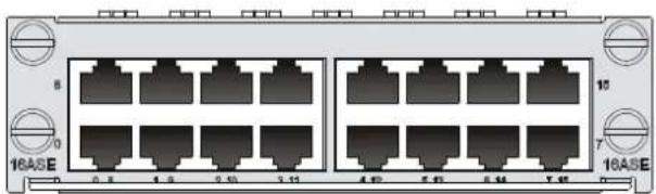
Each channel on the MIM-8ASE/MIM-16ASE has only one LED.
Table 98 LED description
| LED | Description |
| LINK | Off means no link is present;On means a link is present. |
| ACTIVE | Off means no data is being transmitted or received.Flashing means data is being transmitted or received. |
Interface cables and connection methods
For more information about asynchronous serial port cables, see "Asynchronous serial ports."
Voice interface module
- MIM-2FXO
- MIM-4FXS
- MIM-4FXO
- MIM-16FXS
- MIM-4E&M
- MIM-4BSV
- MIM-2VE1
- MIM-2VT1
- MIM-1VE1 • MIM-1VT1
MIM-16FXS
Introduction
The 16-port loop trunk interface module (MIM-16FXS) provides access for 16 channels of analog voice signals over data communication networks. The module provides 16 FXS interfaces. FXS interfaces are analog subscriber line interfaces that provide analog telephone and fax access and also can connect AT0 loop trunks of exchanges.
Interface specifications
Table 99 Interface specifications
| Item | Specification |
| Connector type RJ-11 | |
| Number of connectors 16 (FXS interfaces) | |
| Interface standard | Subscriber circuit interface (FXS) compliant with ITU Q.512.Over-current and over-voltage protection compliant with ITU K.20. |
| Cable type Telephone cable with ferrite core | |
| Dial-up mode DTMF, compliant with GB3378 (Pulse dial-up is not available.) | |
| Bandwidth 300 to 3400 Hz | |
Interface LEDs
Figure 72 MIM-16FXS panel
Table 100 LED description
| LED | Description |
| LINK/ACT | Off means no link is present.Steady green means a link is present and a call connection is being established.Flashing yellow means a link is present and there is a call activity. |
Interface cables and connection methods
For more information about FXS interface cables and connection methods, see "ADSL/BS/FXS/FXO/AM/FCM interface."
MIM-4BSV
Introduction
The 4-port ISDN BRI S/T voice interface module (MIM-4BSV) processes ISDN voice traffic. In the upstream direction, it can be connected to user interfaces on an ISDN switch to receive and decompress, and compress and transmit ISDN BRI digital voice traffic. In the downstream direction, the module can be connected to TE devices to allow their voice traffic to be forwarded through a WAN interface on the router to the Internet to implement VoIP. The interfaces on the MIM-4BSV module are ITU-T I.430-compliant. They use pseudo-ternary coding, providing 192 Kbps rate, and
allow a maximum transmission distance of 1 km (0.6 miles) in point-to-point mode. The MIM-4BSV provides the following features.
- The BSV interfaces support user and network modes for connecting an ISDN network and a TE device, respectively.
- When a BSV interface operates in network mode, the digital voice traffic received on the BSV interface is compressed and forwarded through the CPU on the MPU to a WAN interface. The IP voice traffic received on a WAN interface is forwarded through the CPU on the MPU to the MIM-4BSV. The MIM-4BSV decompresses and sends the voice traffic to the TE device.
- When a BSV interface operates in user mode, the digital voice traffic received from the B channels on the BSV interface is decompressed and forwarded through the CPU on the MPU to a local FXS or FXO analog voice interface. The voice signals received on the local FXS or FXO analog voice interface are processed by VoIP and forwarded through the CPU on the MPU to the MIM-4BSV module. The MIM-4BSV module decompresses and sends the traffic out of the BSV interface to the connected ISDN switch.
- Working in conjunction with the FXS or FXO analog voice interface modules, the MIM-4BSV provides flexibility in voice call routing. • The signaling on the ISDN BRI D channel is processed separately on CPU. • The BSV interfaces can be connected to ISDN phones to supply power to the phones.
- The MIM-4BSV is dedicated to voice applications.
Interface specifications
Table 101 Interface specifications
| Item | Specification |
| Connector | RJ-45 |
| Number of connectors 4 | |
| Interface standard ITU-T I.430, Q.921, Q.931 | |
| Interface rate 192 Kbps | |
| Cable ISDN S interface cable | |
| Supported service Voice access over ISDN S interface cable | |
Interface LEDs
Figure 73 MIM-4BSV panel
Table 102 LED description
| LED | Description |
| LINK | Off means no link is present.On means a link is present. |
| ACT | Slowly flashing means data is being transmitted or received on B1 channel.Fast flashing means data is being transmitted or received on B2 channel.Steady On means data is being transmitted or received on both B1 and B2 channels.Steady Off means no data is being transmitted or received. |
Interface cables and connection methods
For more information about BSV interface cables and connection methods, see "BSV/BSE interface."
MIM-2FXO and MIM-4FXS/MIM-4FXO
Introduction
The MIM-2FXO and MIM-4FXS/MIM-4FXO modules transfer voice signals over data communication networks.
- The 4-port voice subscriber circuit interface module (MIM-4FXS) can provide access for and process 2/4 channels of ordinary analog phone, fax, or AT0 loop trunk of telephone exchange.
- The 2/4-port voice AT0 analog trunk interface module (MIM-2FXO/MIM-4FXO) can provide access for and process 2/4 channels of common user lines of telephone exchange.
Interface specifications
Table 103 Interface specifications
| Item | Specification |
| Connector | RJ-45 |
| Number of connectors | 2 (MIM-2FXO module)4 (MIM-4FXS/MIM-4FXO module) |
| Cable | Telephone cable with ferrite coreE&M trunk (for E&M module, which should be made by users depending on the actual needs at the site.) |
| Interface standard | ITU Q.512-compliant subscriber circuit interface (MIM-4FXS)ITU Q.552-compliant loop trunk interface (MIM-2FXO/MIM-4FXO)ITU K.20-compliant overcurrent and overvoltage protection |
| Dial-up mode DTMF (Dual-Tone Multi-Frequency) but not pulse dial-up | |
| Bandwidth 300 Hz to 3400 Hz | |
Interface LEDs
Figure 74 MIM-2FXO panel
Figure 75 MIM-4FXS panel
Figure 76 MIM-4FXO panel
Table 104 LED description
| LED | Description |
| LINK | Off means no link is present; On means a link is present. |
| ACT | Off means the channel is idle. On means there is call activity. |
Interface cables and connection methods
For more information about FXS/FXO interface cables and connection methods, see "ADSL/BS/FXS/FXO/AM/FCM interface."
MIM-4E&M
Introduction
The 4-port voice E&M analog trunk interface module (MIM-4E&M) provides access for 4 channels of E&M analog trunks to transfer voice signals over data communication networks.
Interface specifications
Table 105 Interface specifications
 |
Interface LEDs
Figure 77 MIM-4E&M panel
Table 106 LED description
| LED | Description |
| LINK | Off means no link is present; On means a link is present. |
| ACT | Off means the channel is idle. On means there is call activity. |
Interface cables and connection methods
For more information about E&M interface cables and connection methods, see "E&M interface."
MIM-1VE1
Introduction
The 1-port E1 voice interface module (MIM-1VE1) handles dense voice signals in a VoIP system. It provides a CE1/PRI/R2 port that allows access of a maximum of 30 channels of voice signals.
Interface specifications
Table 107 Interface specifications
| Item | Specification |
| Connector | D15 |
| Number of connectors 1 | |
| Operating mode | CE1ISDN PRI R2 |
| Interface rate 2.048 Mbps | |
| Cable | E1 120-ohm balanced twisted pair cable75-ohm-to-120-ohm adapter (with BNC connector) |
| Supported service | R2 signalingDSS1 signalingIP FaxGeneral VoIP features in Comware |
Interface LEDs
Figure 78 MIM-1VE1 panel
Table 108 LED description
| LED | Description |
| LINK/ACT | On means carrier signal has been received.Flashing means data is being received or/and transmitted.Off means no carrier signal has been received. |
| LP/AL | On means the interface is in a loopback.Flashing means an AIS, LFA, or RAI alarm signal is present.Off means no loopback or alarm is present. |
| Note:AIS = Alarm indication signal; LFA = loss of frame alignment; RAI = Remote alarm indication | |
Interface cables and connection methods
For more information about E1 interface cables, see "E1 interface."
MIM-1VT1
Introduction
The 1-port T1 voice interface module (MIM-1VT1) handles dense voice signals in the VoIP system. The MIM-1VT1 module is structured in the form of board plus VCPM module plus VPM strip. It provides a CT1/PRI port that allows access of 24 channels of voice signals.
Interface specifications
Table 109 Interface specifications
| Item | Specification |
| Connector | RJ-45 |
| Number of connector 1 | |
| Interface standard | G.703/T1.102G.704AT&T TR 54016AT&T TR 62411ANSI T1.403 |
| Interface rate 1.544 Mbps | |
| Cable type T1 cable (100-ohm standard shielded cable) | |
| Operating mode | CT1ISDN PRI |
| Services | BackupTerminal accessISDN |
Interface LEDs
Figure 79 MIM-1VT1 panel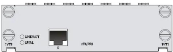
Table 110 LED description
| LED | Description |
| LINK/ACT | On means carrier signal has been received.Flashing means data is being received or/and transmitted.Off means no carrier signal has been received. |
| LP/AL | On means the interface is in a loopback.Flashing means an AIS, LFA, or RAI alarm signal is present.Off means no loopback or alarm is present. |
| Note:AIS = Alarm indication signal; LFA = loss of frame alignment; RAI = Remote alarm indication | |
Interface cables and connection methods
For more information about T1 interface cables and connection methods, see "T1 interface."
MIM-2VE1
Introduction
The 2-port E1 voice interface module (MIM-2VE1) handles dense voice signals in a VoIP system. It provides two CE1/PRI/R2 ports that allow access of a maximum of 60 channels of voice signals.
Interface specifications
Table 111 Interface specifications
| Item | Specification |
| Connector | D15 |
| Number of connectors 2 | |
| Operating mode | CE1ISDN PRI R2 |
| Interface rate 2.048 Mbps | |
| Cable | E1 120-ohm balanced twisted pair cable75ohm-to-120ohm adapter |
| Supported service | R2 signalingDSS1 signalingIP FaxGeneral VoIP features in Comware |
Interface LEDs
Figure 80 MIM-2VE1 panel
Table 112 LED description
| LED | Description |
| LINK/ACT | On means carrier signal has been received.Flashing means data is being received or/and transmitted.Off means no carrier signal has been received. |
| LP/AL | On means the interface is in a loopback.Flashing means an AIS, LFA, or RAI alarm signal is present.Off means no loopback or alarm is present. |
| Note:AIS = Alarm indication signal; LFA = loss of frame alignment; RAI = Remote alarm indication | |
Interface cables and connection methods
For more information about E1 interface cables, see "E1 interface."
MIM-2VT1
Introduction
The 2-port T1 voice interface module (MIM-2VT1) handles dense voice signals in a VoIP system. It provides two CT1/PRI ports that allow access of a maximum of 48 channels of voice signals.
Interface specifications
Table 113 Interface specifications
| Item | Specification |
| Connector | RJ-45 |
| Number of connector 2 | |
| Interface standard | G.703/T1.102G.704AT&T TR 54016AT&T TR 62411ANSI T1.403 |
| Interface rate 1.544 Mbps | |
| Cable type T1 cable (100-ohm standard shielded cable) | |
| Operating mode | CT1ISDN PRI |
| Services | BackupTerminal accessISDN |
Interface LEDs
Figure 81 MIM-2VT1 panel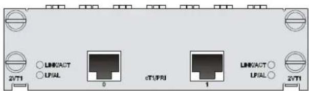
Table 114 LED description
| LED | Description |
| LINK/ACT | On means carrier signal has been received.Flashing means data is being received or/and transmitted.Off means no carrier signal has been received. |
| LP/AL | On means the interface is in a loopback.Flashing means an AIS, LFA, or RAI alarm signal is present.Off means no loopback or alarm is present. |
| Note:AIS = Alarm indication signal; LFA = loss of frame alignment; RAI = Remote alarm indication | |
Interface cables and connection methods
For more information about T1 interface cables and connection methods, see "T1 interface."
HMIM
A wide range of optional HMIMs are available for the MSR series routers. The HMIMs provide multiple types of interfaces such as the synchronous/asynchronous serial interface, Ethernet interface, E1/T1, ISDN BRI/PRI, audio interface, and Layer 2 switching interface.
Ethernet interface switching module
- HMIM-8GSW
- HMIM-24GSW
- HMIM-24GSW-PoE
- RT-HMIM-8GSWF
HMIM-8GSW/HMIM-24GSW/HMIM-24GSW-PoE
Introduction
The 8/24/24-port 1000M Layer 2 Ethernet interface module (HMIM-8GSW/HMIM-24GSW/HMIM-24GSW-PoE) is suitable for a small enterprise network to act as a switching & routing device. It can be connected to PCs and network devices of the enterprise. The HMIM-24GSW-PoE supports power transmission to remote devices over Ethernet cables.
Interface specifications
Table 115 Interface specifications
| Item | Specification |
| Connector | RJ-45 |
| Interface standard | MDI/MDIX |
| Number of connectors | • HMIM-8GSW: 8• HMIM-24GSW/ HMIM-24GSW-PoE: 24 |
| Transmission distance | 100 m (328.08 ft) over category-5 twisted pair cables (both crossover and straight-through) |
| Operating mode | 10/100/1000 Mbps autosensing, full/half duplex |
Interface LEDs
Each GE interface has one green LED.
Figure 82 HMIM-8GSW panel
Figure 83 HMIM-24GSW panel
Figure 84 HMIM-24GSW-PoE panel
Table 116 LED description
| LED | Description |
| Off No link is present. | |
| Steady green A 1000 Mbps link is present. | |
| Flashing green The interface is sending or receiving data at 1000 Mbps. | |
| Steady yellow A 10/100 Mbps link is present. | |
| Flashing yellow The interface is sending or receiving data at 10/100 Mbps. | |
Interface cables and connection methods
For more information about the Ethernet interface cables and connection methods, see "Ethernet interface."
RT-HMIM-8GSWF
Introduction
The 8-port (four fiber ports and four combo interfaces) 100M/1000M Layer 2/Layer 3 Ethernet interface module (RT-HMIM-8GSWF) is suitable for a small enterprise network to act as a switching & routing device. It can be directly connected to PCs and network devices of the enterprise.
Interface specifications
Table 117 Interface specifications
| Item | Specification |
| Number of connectors 8 | |
| Connector type SFP/LC | |
| Interface standard 802.3/802.3u/802.3ab | |
| Operating mode 100/1000 Mbps, full duplex |
Interface LEDs
Figure 85 RT-HMIM-8GSWF panel
Table 118 LED description
| LED | Description |
| LINK | Off means no link is present.On means a link is present. |
| ACT | Off means no data is being transmitted or received on the interface.Flashing means data is being transmitted and/or received. |
Fiber ports, optical fibers, and the connection methods
For more information about fiber ports, optical fibers, and the connection methods, see "Fiber port."
Ethernet interface module
- HMIM-2GEE
- HMIM-4GEE
- HMIM-8GEE
- HMIM-2GEF
- HMIM-4GEF
- HMIM-8GEF
HMIM-2GEE/HMIM-4GEE/HMIM-8GEE
Introduction
The HMIM-GEE module completes the communication between a router and a LAN. It includes the following types:
• HMIM-2GEE—2-port 10Base-T/100Base-TX/1000Base-T Ethernet electrical interface module • HMIM-4GEE—4-port 10Base-T/100Base-TX/1000Base-T Ethernet electrical interface module • HMIM-8GEE—8-port 10Base-T/100Base-TX/1000Base-T Ethernet electrical interface module
Interface specifications
Table 119 Interface specifications
| Item | HMIM-2GEE | HMIM-4GEE | HMIM-8GEE |
| Connector type RJ-45 | |||
| Number of connectors 2 4 8 | |||
| Interface type MDI/MDIX | |||
| Interface standard 802.3, 802.3u, and 802.3ab | |||
| Transmission distance | 100 m (328.08 ft) over category-5 twisted pair cables (both crossover and straight-through) | ||
| Operating mode 10/100/1000 Mbps autosensing, full duplex/half-duplex | |||
Interface LEDs
Figure 86 HMIM-2GEE panel
Figure 87 HMIM-4GEE panel
Figure 88 HMIM-8GEE panel
Table 120 LED description
| LED | Description |
| LINK | Off means no link is present.On means a link is present. |
| ACT | Off means no data is being transmitted or received on the interface.Flashing means data is being transmitted and/or received. |
Interface cables and connection methods
For more information about the Ethernet interface cables and connection methods, see "Ethernet interface."
HMIM-2GEF/HMIM-4GEF/HMIM-8GEF
Introduction
The HMIM-GEF module completes the communication between a router and a LAN. It includes the following types:
• HMIM-2GEF—2-port 10Base-T/100Base-TX/1000Base-T Ethernet optical interface module • HMIM-4GEF—4-port 10Base-T/100Base-TX/1000Base-T Ethernet optical interface module • HMIM-8GEF—8-port 10Base-T/100Base-TX/1000Base-T Ethernet optical interface module
Interface specifications
Table 121 Interface specifications
| Item | HMIM-2GEF | HMIM-4GEF | HMIM-8GEF |
| Connector type SFP/LC | |||
| Number of connectors 2 4 8 | |||
| Interface standard 802.3, 802.3u, and 802.3ab | |||
| Operating mode 1000 Mbps, full duplex | |||
Interface LEDs
Figure 89 HMIM-2GEF panel
Figure 90 HMIM-4GEF panel
Figure 91 HMIM-8GEF panel
Table 122 LED description
| LED | Description |
| LINK | Off means no link is present.On means a link is present. |
| ACT | Off means no data is being transmitted or received on the interface.Flashing means data is being transmitted and/or received. |
Interface cables and connection methods
For more information about the Ethernet interface cables and connection methods, see "Ethernet interface."
POS (SDH/SONET) interface module
- HMIM-1POS
HMIM-1POS
Introduction
The 1-port SDH/SONET interface module (HMIM-1POS) provides interface rates up to 155.52 Mbps (STM-1/OC-3).
The HMIM-1POS uses protocols such as PPP, Frame Relay, and HDLC at the data link layer and IP at the network layer. It allows direct transmission of packets over SONET/SDH.
Interface specifications
Table 123 Interface specifications
| Item | Specification |
| Interface standard SONET OC-3/SDH STM-1 | |
| Number of connectors 1 | |
| Connector type SFP/LC | |
| Interface rate 155.52 Mbps | |
Interface LEDs
Figure 92 HMIM-1POS front panel
Table 124 LED description
| LED | Description |
| LINK/ACT | On means carrier signal has been received.Flashing means data is being received or/and transmitted.Off means no carrier signal has been received. |
| LP/AL | On means the interface is in a loopback.Off means no loopback or alarm is present.Flashing means an alarm indication signal (AIS), loss of frame alignment (LFA) signal, or remote alarm indication (RAI) signal is present. |
Fiber ports, optical fibers, and the connection methods
For more information about fiber ports, optical fibers, and the connection methods, see "Fiber port."
CPOS (SDH/SONET) interface module
- HMIM-1CPOS
HMIM-1CPOS
Introduction
The 1-port channelized SDH/SONET interface module (HMIM-1CPOS) provides one STM-1/OC3-compliant multi-channel interface. It provides an interface rate of up to 155.52 Mbps.
You can set E1 or T1 working mode for the HMIM-1CPOS interface module.
The HMIM-1CPOS interface module is installed in an HMIM slot to receive and transmit data on STM-1 channelized POS interface and to communicate with the CPU through the PCI interface.
The HMIM-1CPOS provides the following features:
- Multiple transceiver modules. • Clear channel (unframed) E1 or T1 • Fractional (framed) E1 or T1 • A maximum of 256 x 64 kbps logical channels
Interface specifications
Table 125 Interface specifications
| Item | Specification |
| Interface standard | SONET OC-3/SDH STM-1 |
| Number of interfaces | 1 |
| Connector type SFP/LC | |
| Interface rate | 155.52 Mbps |
IMPORTANT:
If the interface receives signal over a long-distance optical fiber, make sure the transmission distance is longer than 25 km (15.53 miles). If the transmission distance is shorter than 25 km (15.53 miles), use an optical attenuator to reduce the optical power.
Interface LEDs
Figure 93 HMIM-1CPOS front panel
Table 126 LED description
| LED | Description |
| LINK/ACT | On: Carrier signal has been received.Off: No carrier signal has been received.Flashing: Data is being received and/or transmitted. |
| LP/AL | On: The interface is in a loopback.Off: No loopback or alarm is present.Flashing: An alarm indication signal (AIS), loss of frame alignment (LFA) signal, or remote alarm indication (RAI) signal is present. |
Fiber ports, optical fibers, and the connection methods
For more information about fiber ports, optical fibers, and the connection methods, see "Fiber port."
Setting the working mode
- Insert the HMIM-1CPOS interface module in an HMIM slot.
- Power on the device.
- Enter system view.
- Set the working mode of the HMIM-1CPOS interface module.
<Sysname> system-view
- Set the working mode to E1.
- Set the working mode to T1.
[Sysname] card-mode slot 4 e1
[Sysname] card-mode slot 4 t1
E1/T1 interface module
- HMIM-2E1
- HMIM-4E1
- HMIM-4E1-F
- HMIM-8E1
- HMIM-2T1
- HMIM-4T1-F
- RT-HMIM-8E1T1
- RT-HMIM-8E1T1-F
HMIM-2E1/HMIM-4E1/HMIM-4E1-F
Introduction
The 2-port channelized E1/PRI interface module (HMIM-2E1) and 4-port channelized E1/PRI interface module (HMIM-4E1) transmit, receive, and process E1 data traffic. In addition, you can use these modules for CE1 access and ISDN PRI.
The HMIM-4E1-F module differs from the HMIM-4E1 module in the following ways:
- The FE1 operating mode supported by the E1-F module allows only one n x 64 Kbps bundle to be formed on each interface, where n ranges from 1 to 31. However, an E1 module allows arbitrary grouping of 31 channels and multiple bundles.
- The E1-F modules do not support the PRI mode.
Interface specifications
Table 127 Interface specifications
| Item | HMIM-2E1/HMIM-2E1-F | HMIM-4E1/HMIM-4E1-F |
| Connector type DB15 DB25 | ||
| Number of connectors | 2 | 1 |
| Interface standard | G.703 and G.704 | |
| Interface rate 2.048 Mbps | ||
| Cable type | E1 75-ohm unbalanced coaxial cableE1 120-ohm balanced twisted pair cable120-ohm 4E1 conversion cable (only supported by the HMIM-4E1/HMIM-4E1-F)75-ohm 4E1 conversion cable (only supported by the HMIM-4E1/HMIM-4E1-F)Coaxial connector, network interface connector, and 75-ohm to 120-ohm adapter (with BNC connector) | |
| Operating mode | E1, CE1, ISDN PRI (only supported by the HMIM-2E1/HMIM-4E1)FE1 (only supported by the HMIM-4E1-F) | |
| Supported services | BackupTerminal access serviceISDN PRI (only supported by the HMIM-2E1/HMIM-4E1) | |
Interface LEDs
Figure 94 HMIM-2E1 panel
Figure 95 HMIM-4E1 panel
Figure 96 HMIM-4E1-F panel
Table 128 LED description
| LED | Description |
| LINK/ACT | On means carrier signal has been received.Flashing means data is being received or/and transmitted.Off means no carrier signal has been received. |
| LP/AL | On means the interface is in a loopback.Off means no loopback or alarm is present.Flashing means an alarm indication signal (AIS), loss of frame alignment (LFA) signal, or remote alarm indication (RAI) signal is present. |
| LINK | On means carrier signal has been received.Off means no carrier signal has been received. |
| ACTIVE | Off means no data is being transmitted or received.Flashing means data is being received or/and transmitted. |
Interface cables and connection methods
For more information about E1 interface cables, see "E1 interface."
HMIM-8E1
Introduction
The 8-port channelized E1/PRI interface module (HMIM-8E1) transmits, receives, and processes eight channels of E1 data traffic. In addition, you can use the module for CE1 access and ISDN PRI.
NOTE:
For an HMIM-8E1 module, the system automatically creates a serial interface for each timeslot bundle formed on a controller E1 interface.
Interface specifications
Table 129 Interface specifications
| Item | Description |
| Connector type D68 | |
| Number of connectors 1 | |
| Interface standard G.703 | |
| Interface rate 2.048 Mbps | |
| Cable type 75-ohm 8E1 conversion cable | |
| Cable characteristic impedance 75 ohm | |
| Operating mode E1, CE1, ISDN PRI | |
| Supported services | BackupTerminal access serviceISDN PRI |
Interface LEDs
Figure 97 HMIM-8E1 (75-ohm) panel
Figure 98 LED description
| LED | Description |
| LINK/ACT | On means carrier signal has been received.Flashing means data is being received or/and transmitted.Off means no carrier signal has been received. |
| LP/AL | On means the interface is in a loopback.Off means no loopback or alarm is present.Flashing means an alarm indication signal (AIS), loss of frame alignment (LFA) signal, or remote alarm indication (RAI) signal is present. |
Interface cables and connection methods
For more information about E1 interface cables, see "E1 interface."
HMIM-2T1/HMIM-4T1-F
Introduction
The 2-port channelized CT1/PRI interface module (HMIM-2T1) transmits, receives, and handles T1 data streams. In addition, you can use the module for CT1 access and ISDN PRI.
The 4-port fractional T1 interface module (HMIM-4T1-F) differs from the HMIM-CT1 module in the following ways:
- FT1 operating mode supported by T1-F modules allows only one bundle. The time slots can only be bundled into one n x 64 Kbps/56 Kbps channel, where the value range of n is 1 to 24. However, a CT1 module allows arbitrary grouping of the 24 channels. T1-F does not support the PRI mode.
NOTE:
For a T1 module, the system automatically creates a serial interface for each timeslot bundle formed on a controller T1 interface.
Interface specifications
Table 130 Interface specifications
| Item | Specification |
| Connector type RJ45 | |
| Number of connectors | • 2 (HMIM-2T1)• 4 (HMIM-4T1-F) |
| Interface standard | G.703/T1 102G.704AT & T TR 54016AT & T TR 62411ANSI T1.403 |
| Interface rate 1.544 Mbps | |
| cable type T1 cable (100-ohm shielding network cable) | |
| Operating mode | CT1, ISDN PRI (only supported by the HMIM-2T1)FT1 (only supported by the HMIM-4T1-F) |
| Supported services | BackupTerminal access serviceISDN PRI (only supported by the HMIM-2T1) |
Interface LEDs
Figure 99 HMIM-2T1 panel
Figure 100 HMIM-4T1-F panel
Table 131 LED description
| LEDs | Description |
| LINK/ACT | On means the carrier signal has been received.Off means no carrier signal has been received.Flashing means data is being transmitted or/and received. |
| LP/AL | On means the interface is in a loopback.Off means no loopback or alarm is present.Flashing means an alarm indication signal (AIS), loss of frame alignment (LFA) signal, or remote alarm indication (RAI) signal is present. |
Interface cables and connection methods
For more information about T1 interface cables and connection methods, see "T1 interface."
RT-HMIM-8E1T1/RT-HMIM-8E1T1-F
Introduction
• RT-HMIM-8E1T1 module
The 8-port channelized E1/CE1/T1/CT1/PRI interface module transmits, receives, and handles T1 data streams. In addition, you can use the module for CT1 access and ISDN PRI. The module allows arbitrary grouping of 31 channels.
• RT-HMIM-8E1T1-F module
The 8-port fractional T1 interface module allows only one bundle. The time slots can only be bundled into one n x 64 Kbps/56 Kbps channel, where the value range of n is 1 to 31. The module does not support the PRI mode.
• RT-HMIM-8E1T1(-F) jumper settings
You can set an interface to a 75-ohm E1 interface, 100-ohm T1 interface, or 120-ohm E1 interface at the CLI or by using the jumper connection method. By default, an interface is a 75-ohm E1 interface.
For a 75-ohm E1 interface, the jumper is connected to pins 1 and 2, pins 7 and 8, and pins 11 and 12. For a 100-ohm T1 or 120-ohm E1 interface, the jumper is connected to pins 1 to 3, pins 5 to 7, pins 9 and 10, and pins 11 to 13.
Figure 101 Jumper settings
NOTE:
- An interface corresponds to a jumper connector. Pin settings for the jumper connectors are the same. • Each interface comes with four jumper caps.
- All interfaces must operate in the same mode simultaneously.
Interface specifications
Table 132 Interface specifications
| Item | Specification |
| Connector type RJ-45 | |
| Number of connectors 8 | |
| Interface standard | G.703/G.704T1 102AT&T TR 54016AT&T TR 62411ANSI T1.403 |
| Interface rate | 1.544 Mbps2.048 Mbps |
| Supported cable | E1 75-ohm unbalanced twisted pair cableE1 120-ohm balanced twisted pair cable, 2 m (6.56 ft), 15 m (49.21 ft), or 30 m (98.43 ft)T1 cable (100-ohm shielding network cable)Coaxial connector, network connector, 75-to-120-ohm adapter (with BNC connector) |
| Operating mode | E1/T1/CE1T1/ISDN PRI (only supported by the RT-HMIM-8E1T1)FE1T1 (only supported by the RT-HMIM-8E1T1-F) |
| Supported services | BackupTerminal access serviceISDN PRI (only supported by the HMIM-8E1T1) |
Interface LEDs
Figure 102 RT-HMIM-8E1T1 panel
Figure 103 RT-HMIM-8E1T1-F panel
Table 133 LED description
| LED | Description |
| LINK/ACT | On means the carrier signal has been received.Off means no carrier signal has been received.Flashing means data is being transmitted or/and received. |
| LP/AL | On means the interface is in a loopback.Off means no loopback or alarm is present.Flashing means an AIS, LFA signal, or RAI signal is present. |
Interface cables and connection methods
For more information about E1 interface cables, see "E1 interface."
For more information about T1 interface cables, see "T1 interface."
E3/T3 interface module
- HMIM-1CE3
- HMIM-1CT3
HMIM-1CE3
Introduction
The 1-port channelized E3 interface module (HMIM-1CE3) provides the following features:
- Transmits, receives and handles one channel of E3 fast traffic, and provides access for E3 traffic when operating in E3 mode.
- Provides low-speed accessing service at n x 64 kbps when operating in CE3 mode. n is smaller than or equal to 128.
NOTE:
E3 represents the tertiary group rate (34.368 Mbps) of E system in the TDM system. An E3 channel can be channelized into 16 E1 lines through the demultiplexing processes of E23 and E12. Each E1 line supports both the E1 and CE1 modes. E23 is used to indicate either E2-to-E3 multiplex or E3-to-E2 demultiplex, and E12 to indicate E1-to-E2 multiplex or E2-to-E1 demultiplex. "E23" and "E12" discussed here represent the demultiplex process.
Interface specifications
Table 134 Interface specifications
| Item | Specification |
| Connector type SMB | |
| Number of connectors 2 | |
| Interface standard G.703, G.704, and G.751 | |
| Interface rate 34.368 Mbps | |
| Cable type E3 cable (75-ohm coaxial cable) | |
| Operating mode | E3CE3 |
| Supported services E3 leased line | |
Interface LEDs
Figure 104 HMIM-1CE3 panel
Table 135 LED description
| LED | Description |
| LINK/ACT | On means carrier signal has been received.Flashing means data is being received or/and transmitted.Off means no carrier signal has been received. |
| LP/AL | On means the interface is in a loopback.Off means no loopback or alarm is present.Flashing means an alarm indication signal (AIS), loss of frame alignment (LFA) signal, or remote alarm indication (RAI) signal is present. |
Interface cables and connection methods
For more information about E3 interface cables and connection methods, see "E3/T3 interface."
HMIM-1CT3
Introduction
The 1-port channelized T3 interface module (HMIM-1CT3) provides the following features:
- Transmits, receives, and handles one channel of T3 fast traffic, and provides access for T3 traffic when operating in T3 mode.
- Provides low-speed accessing service at n x 64 kbps/56 kbps when operating in CT3 mode. n is smaller than or equal to 128.
NOTE:
T3 represents the tertiary group rate (44.736 Mbps) of T system in the TDM system. A T3 channel can be channelized into 28 T1 lines through the demultiplexing processes of T23 and T12. Each T1 line supports the operating modes of CT1. T23 is used to indicate either T2-to-T3 multiplex or T3-to-T2 demultiplex, and T12 to indicate T1-to-T2 multiplex or T2-to-T1 demultiplex. "T23" and "T12" discussed here represent the demultiplex process.
Interface specifications
Table 136 Interface specifications
| Item | Specification |
| Connector type SMB | |
| Number of connectors 2 | |
| Interface standard | G.703G.704G.752AT & T TR 54014AT & T TR 62415ANSI T1.107 |
| Interface rate 44.736 Mbps | |
| Cable type T3 cable (75-ohm coaxial cable) | |
| Operating mode | T3CT3 |
| Supported services T3 leased line | |
Interface LEDs
Figure 105 HMIM-1CT3 panel
| LED | Description |
| LINK/ACT | On means carrier signal has been received.Flashing means data is being received or/and transmitted.Off means no carrier signal has been received. |
| LP/AL | On means the interface is in a loopback.Off means no loopback or alarm is present.Flashing means an alarm indication signal (AIS), loss of frame alignment (LFA) signal, or remote alarm indication (RAI) signal is present. |
Interface cables and connection methods
For more information about T3 interface cables and connection methods, see "E3/T3 interface."
Serial interface module
- HMIM-4SAE
- HMIM-8SAE
- HMIM-16ASE
HMIM-4SAE/HMIM-8SAE
Introduction
The 4-port SAE module (HMIM-4SAE) and 8-port SAE module (HMIM-8SAE) are enhanced high-speed synchronous/asynchronous serial interface modules. The SAE modules are the same as the SA modules except that the SAE modules support additional protocols, for example, RS449, X.21, and RS530.
Interface specifications
Table 138 Interface specifications
| Item | Synchronous | Asynchronous | |
| Connector type D28 | |||
| Number of connectors | 4 (HMIM-4SAE)8 (HMIM-8SAE) | ||
| Interface standard and operating mode | V.24 V.35, RS449, X.21, and RS530 | RS232 | |
| DTE and DCE DTE and DCE | |||
| Minimum baud rate (bps) 1200 1200 300 | |||
| Maximum baud rate (bps) 64 | k 2.048 M 115.2 | ||
| cable type | V.24 (RS232) DTE cableV.24 (RS232) DCE cableV.35 DTE cableV.35 DCE cableX.21 DTE cableX.21 DCE cableRS449 DTE cableRS449 DCE cableRS530 DTE cableRS530 DCE cable | ||
| Supported services | DDN leased lineTerminal access service | Dialup through modemsBackupAsynchronous leased lineDumb terminal access | |
Interface LEDs
Figure 106 HMIM-4SAE panel
Table 139 LED description
| LED | Description |
| LINK | Off means no link is present.On means a link is present. |
| ACT | Off means no data is being transmitted or received.Flashing means data is being received or/and transmitted. |
Figure 107 HMIM-8SAE panel
Table 140 LED description
| LED | Description |
| LINK/ACT | On means a link is present.Off means no data is being transmitted or received.Flashing means data is being received or/and transmitted. |
Interface cables and connection methods
For more information about synchronous/asynchronous serial port cables, see "Synchronous/asynchronous serial ports."
HMIM-16ASE
Introduction
The 16-port ASE module (HMIM-16ASE) is an enhanced asynchronous serial interface module that transmits, receives, and handles asynchronous serial interface data streams. It uses RJ-45 connectors and AUX cables.
Interface specifications
Table 141 Interface specifications
| Item | Specification |
| Connector type RJ45 | |
| Number of connectors 16 | |
| Interface standard and operating mode | RS232 |
| cable type | AUX cableStandard (straight-through) Ethernet cableHMIM-16ASE dumb terminal cable |
| Minimum baud rate (bps) 300 | |
| Maximum baud rate (bps) 115.2 k | |
| Supported services | Dialup through ModemBackupTerminal access serviceAsynchronous leased line service |
Interface LEDs
Figure 108 HMIM-16ASE panel
Table 142 LED description
| LED | Description |
| N/A | On means a link is present.Off means no link is present.Flashing means data is being received or/and transmitted. |
Interface cables and the connection methods
For more information about asynchronous serial port cables, see "Asynchronous serial ports."
Voice interface module
- HMIM-16FXS
- HMIM-2VE1
Introduction
The 16-port loop trunk interface module HHMIM-16FXS provides access for and handles 16 channels of analog voice signals over data communication networks. The module provides 16 FXS interfaces.
FXS interfaces are analog subscriber line interfaces that provide analog telephone and fax access and also can connect ATO loop trunks of exchanges.
Interface specifications
Table 143 Interface specifications
| Item | Specification |
| Connector type RJ-11 | |
| Number of connectors 16 (FXS interfaces) | |
| Interface standard | ITU Q.512-compliant subscriber circuit interface (FXS)ITU K.20-compliant over-current and over-voltage protection |
| Cable type Telephone cable with ferrite core | |
| Dial-up mode DTMF, compliant with GB3378 (Pulse dial-up is not available.) | |
| Bandwidth 300 to 3400 Hz | |
Interface LEDs
Figure 109 HMIM-16FXS front panel
Table 144 LED descriptions
| LED | Description |
| LINK/ACT | Steady green: A link is present and a call connection is being established.Off: No link is present.Flashing: A link is present and there is a call activity. |
Interface cables and connection methods
For more information about FXS interface cables and connection methods, see "ADSL/BS/FXS/FXO/AM/FCM interface."
HMIM-2VE1
Introduction
The 2-port E1 voice interface module (HMIM-2VE1) handles dense voice signals in VoIP systems. It provides two CE1/PRI/R2 ports that allow access to a maximum of 60 channels of voice signals.
Interface specifications
Table 145 Interface specifications
| Item | Specification |
| Connector | D15 |
| Number of connectors 2 | |
| Operating mode | CE1ISDN PRIR2 |
| Interface rate 2.048 Mbps | |
| Cable type | E1 75-ohm unbalanced coaxial cableE1 120-ohm balanced twisted pair cableCoaxial connector, network interface connector, and 75-to-120-ohm adapter (with BNC connector) |
| Supported service | R2 signalingDSS1 signalingIP FaxGeneral VoIP features in Comware |
Interface LEDs
Figure 110 HMIM-2VE1 panel
Table 146 LED description
| LED | Description |
| LINK/ACT | On means carrier signal has been received.Off means no carrier signal has been received.Flashing means data is being received and/or transmitted. |
| LP/AL | On means the interface is in a loopback.Off means no loopback or alarm is present.Flashing means an alarm indication signal (AIS), loss of frame alignment (LFA) signal, or remote alarm indication (RAI) signal is present. |
Interface cables and connection methods
For more information about E1 interface cables and connection methods, see "E1 interface."
HMIM-2VT1
Introduction
The 2-port T1 voice interface module HMIM-2VT1 handles dense voice signals in VoIP systems. It provides two CT1/PRI ports that allow access to a maximum of 48 channels of voice signals.
Interface specifications
Table 147 Interface specifications
| Item | Specification |
| Connector | RJ-45 |
| Number of connector 2 | |
| Interface standard | G.703/T1.102G.704AT & T TR 54016AT & T TR 62411ANSI T1.403 |
| Interface rate 1.544 Mbps | |
| Cable type T1 cable (100-ohm standard shielded cable) | |
| Operating mode | CT1ISDN PRI |
| Services | BackupTerminal accessISDN |
Interface LEDs
Figure 111 HMIM-2VT1 panel
Table 148 LED description
| LED | Description |
| LINK/ACT | On: Carrier signal has been received.Off: No carrier signal has been received.Flashing: Data is being received and/or transmitted. |
| LP/AL | On: The interface is in a loopback.Off: No loopback or alarm is present.Flashing: An alarm indication signal (AIS), loss of frame alignment (LFA) signal, or remote alarm indication (RAI) signal is present. |
Interface cables and connection methods
For more information about T1 interface cables and connection methods, see "T1 interface."
HMIM-1VE1
Introduction
The 1-port E1 voice interface module (HMIM-1VE1) handles dense voice signals in VoIP systems. It provides a CE1/PRI/R2 port that allows access to a maximum of 30 channels of voice signals.
Interface specifications
Table 149 Interface specifications
| Item | Specification |
| Connector | D15 |
| Number of connectors 1 | |
| Operating mode | CE1ISDN PRIR2 |
| Interface rate 2.048 Mbps | |
| Cable | E1 75-ohm unbalanced coaxial cableE1 120-ohm balanced twisted pair cableCoaxial connector, network interface connector, and 75ohm-to-120ohm adapter (with BNC connector) |
| Supported service | R2 signalingDSS1 signalingIP FaxGeneral VoIP features in Comware |
Interface LEDs
Figure 112 HMIM-1VE1 panel
Table 150 LED description
| LED | Description |
| LINK/ACT | On means carrier signal has been received.Off means no carrier signal has been received.Flashing means data is being received and/or transmitted. |
| LP/AL | On means the interface is in a loopback.Off means no loopback or alarm is present.Flashing means an alarm indication signal (AIS), loss of frame alignment (LFA) signal, or remote alarm indication (RAI) signal is present. |
Interface cables and connection methods
For more information about E1 interface cables and connection methods, see "E1 interface."
HMIM-1VT1
Introduction
The 1-port T1 voice interface module (HMIM-1VT1) handles dense voice signals in VoIP systems. It provides a CT1/PRI port that allows access to 24 channels of voice signals.
Interface specifications
Table 151 Interface specifications
| Item | Specification |
| Connector | RJ-45 |
| Number of connector 1 | |
| Interface standard | G.703/T1.102G.704AT & T TR 54016AT & T TR 62411ANSI T1.403 |
| Interface rate 1.544 Mbps | |
| Cable type T1 cable (100-ohm standard shielded cable) | |
| Operating mode | CT1ISDN PRI |
| Services | BackupTerminal accessISDN |
Interface LEDs
Figure 113 HMIM-1VT1 panel
Table 152 LED description
| LED | Description |
| LINK/ACT | On means carrier signal has been received.Off means no carrier signal has been received.Flashing means data is being received and/or transmitted. |
| LP/AL | On means the interface is in a loopback.Off means no loopback or alarm is present.Flashing means an alarm indication signal (AIS), loss of frame alignment (LFA) signal, or remote alarm indication (RAI) signal is present. |
Interface cables and connection methods
For more information about T1 interface cables and connection methods, see "T1 interface."
HMIM-4FXS/HMIM-4FXO
Introduction
The 4-port voice subscriber circuit interface module (HMIM-4FXS) processes and transmits voice signals for 2/4 regular analog phones, faxes, or AT0 loop trunks of telephone exchanges over data communications networks.
The 4-port voice AT0 analog trunk interface module (HMIM-4FXO) processes and transmits voice signals for 2/4 loops of telephone exchanges over data communications networks.
Interface specifications
Table 153 Interface specifications
| Item Specification | |
| Connector | RJ-45 |
| Number of connectors | 4 |
| Cable | Telephone cable with ferrite coreE&M trunk cable (only for E&M modules, made on site) |
| Interface standard | ITU Q.512-compliant subscriber circuit interface (HMIM-4FXS)ITU Q.552-compliant loop trunk interface (HMIM-4FXO)ITU K.20-compliant over-current and over-voltage protection |
| Dial-up mode | DTMF, compliant with GB3378 (Pulse dial-up is not available.) |
| Bandwidth | 300 Hz to 3400 Hz |
Interface LEDs
Figure 114 HMIM-4FXS panel
Figure 115 HMIM-4FXO panel
Table 154 LED description
| LED | Description |
| LINK | On means a link is present.Off means no link is present. |
| ACT | On means there is call activity.Off means the channel is idle. |
Interface cables and connection methods
For more information about FXS/FXO interface cables and connection methods, see "ADSL/BS/FXS/FXO/AM/FCM interface."
HMIM-4E&M
Introduction
The 4-port voice E&M analog trunk interface module (HMIM-4E&M) provides and transmits voice signals for 4 E&M analog trunks over data communications networks.
Interface specifications
Table 155 Interface specifications
| Item Specification | |
| Connector | RJ-45 |
| Number of connectors | 4 |
| Cable type | Telephone cable with ferrite coreE&M trunk cable (only for E&M modules, made on site) |
| Interface standard | G.712-compliant E&M trunk interface (HMIM-4E&M), E&M interface (supporting Bell type I, II, III, V, and support 2-wire and 4-wire)ITU K.20-compliant over-current and over-voltage protection |
| Dial-up mode | DTMF, compliant with GB3378 (Pulse dial-up is not available.) |
| Bandwidth | 300 Hz to 3400 Hz |
Interface LEDs
Figure 116 HMIM-4E&M panel
Table 156 LED description
| LED | Description |
| LINK | On means a link is present.Off means no link is present. |
| ACT | On means there is call activity.Off means the channel is idle. |
Interface cables and connection methods
For more information about E&M interface cables and connection methods, see "E&M interface."
FIC/DFIC
For modular MSR series routers, a wide range of optional FICs/DFICs are available, which provide multiple types of interfaces, such as synchronous/asynchronous serial interface, Ethernet interface, E1/T1, ISDN BRI/PRI, audio interface, and Layer 2 switching interface.
Among these interface modules, the Layer 2 switching interface modules (FIC-16FSW and DFIC-24FSW) each have a PoE-capable module. The module provides -48 VDC power to remote PDs (such as IP phone, WLAN AP, and network camera) through straight-through network cables if it is installed on a PoE router.
Ethernet switching module
- FIC-16FSW
- FIC-16FSW-PoE
- DFIC-24FSW
- DFIC-24FSW-PoE
FIC-16FSW/FIC-16FSW-PoE/DFIC-24FSW/DFIC-24FSW-PoE
Introduction
The 16/24-port 10/100 Mbps Ethernet Layer 2 switching MIM interface module (FIC-16FSW/FIC-16FSW-PoE/DFIC-24FSW/DFIC-24FSW-PoE) is used on the HPE MSR50 series router. A router installed with FIC-16FSW/DFIC-24FSW modules can act as a switching/routing integrated device on a small-sized enterprise network to connect PCs and network devices inside the network. The interfaces provided on the FIC-16FSW/FIC-16FSW-PoE and DFIC-24FSW/DFIC-24FSW-PoE are as follows:
The FIC-16FSW/FIC-16FSW-PoE provides the following features:
• 16 10/100 Mbps RJ-45 connector interfaces on the FIC-16FSW module • One 10/100/1000 Mbps gigabit RJ-45 connector electrical interface on the FIC-16FSW module - 1 SFP fiber interface (Fiber interfaces and gigabit electrical interfaces share the MAC layer) on the FIC-16FSW module
The DFIC-24FSW/DFIC-24FSW-PoE provides the following features:
- 2 SFP fiber interfaces (Fiber interfaces and gigabit electrical interfaces share the MAC layer) on the DMIM-24FSW module. By default, the electrical interfaces take effect.
Interface specifications
Table 157 Interface specifications
| Item | FIC-16FSW/FIC-16FSW-PoE module | DFIC-24FSW/DFIC-24FSW-PoE module |
| Connector | RJ-45SFP | |
| Interface type MDI/MDIX | ||
| Number of connectors | 16 x 100 Mbps RJ-45 connectorsone 1000 Mbps RJ-45 connectorsOne SFP connector | 24 x 100 Mbps RJ-45 connectorsTwo 1000 Mbps RJ-45 connectorsTwo SFP connectors |
| Transmission distance | 100 m (328.08 ft) over category-5 twisted pair cables (both crossover and straight-through) | |
| Operating mode 10/100 | Mbps autosensing, full/half duplex | |
Interface LEDs
On the FIC-16FSW/FIC-16FSW-PoE/DFIC-24FSW/DFIC-24FSW-PoE panel, each port has one green LED.
Figure 117 FIC-16FSW panel
Figure 118 FIC-16FSW-PoE panel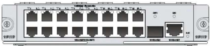
Table 158 LED description for the
FIC-16FSW/FIC-16FSW-PoE/DFIC-24FSW/DFIC-24FSW-PoE FE ports
| LED | Description |
| Steady green A link is present, but no data is being transmitted and received. | |
| Off No link is present. | |
| Flashing green A link is present and data is being transmitted and received (ACT). | |
Table 159 LED description for the FIC-16FSW/FIC-16FSW-PoE/DFIC-24FSW/DFIC-24FSW-PoE GE ports
| LED | Description |
| Off No link is present. | |
| Steady green A 1000 Mbps link is present, but no data is being transmitted and received. | |
| Flashing green A 1000 Mbps link is present and data is being transmitted and received (ACT). | |
| Steady yellow A 100 Mbps link is present, but no data is being transmitted and received. | |
| Flashing yellow | A 100 Mbps link is present and data is being transmitted and received (ACT). |
Table 160 LED description for the FIC-16FSW/FIC-16FSW-PoE/DFIC-24FSW/DFIC-24FSW-PoE fiber ports
| LED | Description |
| Off No link is present. | |
| Steady green A link is present, but no data is being transmitted and received. | |
| Flashing green A link is present and data is being transmitted and received (ACT). | |
| Steady yellow Error prompt | |
NOTE: The two GE ports on the DFIC-24FSW-PoE do not support PoE.
Interface cables and connection methods
For more information about the Ethernet interface cables and connection methods, see "Ethernet interface."
Ethernet interface module
• FIC-2FE - FIC-4FE - FIC-1GBE - FIC-2GBE - FIC-1GEF • FIC-2GEF
FIC-2FE/FIC-4FE
Introduction
The 2-port and 4-port 10Base-T/100Base-TX fast Ethernet interface modules (FIC-2FE, and FIC-4FE) are typically used for communication between the router and LAN.
Interface specifications
Table 161 Interface specifications
| Item | Specification | |
| FIC-2FE | FIC-4FE | |
| Connector | RJ-45 | |
| Number of connectors | 2 | 4 |
| Transmission distance | 100 m (328.08 ft) over category-5 twisted pair cables (both crossover and straight-through) | |
| Operating mode | 10/100 Mbps auto-sensing, full duplex/half-duplex | |
| Supported frame format | Ethernet_IIEthernet_SNAP | |
Interface LEDs
Figure 121 FIC-2FE panel
Figure 122 FIC-4FE panel
| LED | Description |
| LINK | Off means no link is present;On means a link is present. |
| ACT | Off means no data is being transmitted or received on the interface.Flashing means data is being transmitted and/or received. |
Interface cables and connection methods
For more information about the Ethernet interface cables and connection methods, see "Ethernet interface."
FIC-1GBE/FIC-2GBE
Introduction
The 1-port/2-port 10Base-T/100Base-TX/1000Base-T Ethernet electrical interface module (FIC-1GBE/FIC-2GBE) is used for router-to-LAN communication.
Interface specifications
Table 163 Interface specifications
| Item | FIC-1GBE | FIC-2GBE |
| Connector | RJ-45 | |
| Number of connectors 1 2 | ||
| Interface type MDI/MDIX | ||
| Interface standard 802.3, 802.3u, and 802.3ab | ||
| Transmission distance | 100 m (328.08 ft) over category-5 twisted pair cables (both crossover and straight-through) | |
| Operating mode 10/100/1000 Mbps auto-sensing, half-duplex/full duplex | ||
Interface LEDs
Figure 123 FIC-1GBE panel
Figure 124 FIC-2GBE panel
Table 164 LED description
| LED | Description |
| LINK | Off means no link is present;On means a link is present. |
| ACT | Off means no data is being transmitted or received.Flashing means data is being transmitted and/or received. |
Fiber ports, optical fibers, and the connection method
For more information about fiber ports, optical fibers, and the connection methods, see "Fiber port."
FIC-1GEF/FIC-2GEF
Introduction
The 1-port/2-port 1000Base-SX/1000Base-LX GE optical interface module (FIC-1GEF/FIC-2GEF) is used for router-to-LAN communication. The FIC-1GEF/FIC-2GEF supports multiple transceiver modules.
Interface specifications
Table 165 Interface specifications
| Item FIC-1GEF | FIC-2GEF | |
| Connector | SFP | |
| Number of interfaces | 1 | 2 |
| Interface standard | 802.3, 802.3u, 802.3ab | |
| Operating mode 1000 Mbps, full duplex | ||
Interface LEDs
Figure 125 FIC-1GEF panel
Figure 126 FIC-2GEF panel
Table 166 LED description
| LED | Description |
| LINK | Off means no link is present;On means a link is present. |
| ACT | Off means no data is being transmitted or received;Flashing means data is being received or/and transmitted. |
Fiber ports, optical fibers, and the connection method
For more information about fiber ports, optical fibers, and the connection methods, see "Fiber port."
ATM interface module
- FIC-IMA-4E1
- FIC-IMA-8E1
- FIC-1AE3
- FIC-1AT3 • FIC-1ATM-OC3
FIC-IMA-4E1/FIC-IMA-8E1
Introduction
The 4-port/8-port E1 ATM inverse multiplexing interface module (FIC-IMA-4E1/FIC-IMA-8E1) provides four/eight E1 interfaces that support the IMA (inverse multiplexing for ATM) technology.
IMA technology combines multiple low-speed links into a group to support a high-speed ATM cell stream. It distributes an ATM cell stream over multiple low-speed E1 links on a cell-by-cell basis at the transmission end and reassembles the cells on the low-speed E1 links into the original stream at the far end. This technology provides a scalable and cost-effective solution, and is typically used in PDH networks to transport ATM cells.
Interface specifications
Table 167 Interface specifications
| Item | Specification | |
| FIC-IMA-4E1 (75-ohm) FIC-IMA-8E1 (75-ohm) | ||
| Connector | D68 | |
| Number of connectors 1 | ||
| Interface standard ITU-G.703, ITU-G.704 | ||
| Interface rate 2.048 Mbps | ||
| Cable type 75-ohm 4E1 conversion cable 75-ohm 8E1 conversion cable | ||
| Max transmission distance | 500 m (1640.4 ft) | |
| Operating mode ATM E1 independent link/IMA bundle mode | ||
| Supported service AAL5 | ||
| Protocol PPPoA, PPPoEoA, IPoA, IPoEoA | ||
| Transmission rate CBR/VBR-rt/VBR-nrt/UBR | ||
Interface LEDs
Figure 127 75-ohm FIC-IMA-4E1 panel
Figure 128 75-ohm FIC-IMA-8E1 panel
| LED | Description |
| LINK | Off means no link is present;On means a link is present. |
| ACT | Off means no data is being transmitted or received;Flashing means data is being received or transmitted. |
Interface cables and connection methods
For more information about E1 interface cables, see "E1 interface."
FIC-IMA-8T1
Introduction
The 8-port T1 ATM inverse multiplexing interface module (FIC-IMA-8T1) provides four/eight T1 interfaces that support the IMA technology.
Interface specifications
Table 169 Interface specifications
| Item | Specification |
| Connector | D68 |
| Number of connectors 1 | |
| Interface standard ITU-G.703, ITU-G.704 | |
| Cable type 8T1 conversion cable (100-ohm straight-through shielded) | |
| Max transmission distance | 150 m (492.1 ft) |
| Operating mode ATM T1 | independent link/IMA bundle mode |
| Supported service AAL5 | |
| Protocol PPPoA, PPPoEoA, IPoA, IPoEoA | |
| Transmission rate CBR/VBR-rt/VBR-nrt/UBR | |
Interface LEDs
Figure 129 FIC-IMA-8T1 panel
Table 170 LED description
| LED | Description |
| LINK | Off means no link is present;On means a link is present. |
| ACT | Off means no data is being transmitted or received;Flashing means data is being received or transmitted. |
Interface cables and connection methods
For more information about T1 interface cables and connection methods, see "T1 interface."
FIC-1AE3
Introduction
The 1-port 34 Mbps ATM-E3 interface module (FIC-1AE3) provides the following features:
- Two ATM cell mapping modes: ATM direct mapping (ADM) and physical layer convergence protocol (PLCP).
- Scrambling in data transmission.
- Line clock (when working as DTE interface) and internal clock (when working as DCE interface).
- Four types of test measures: local cell loopback, local loopback, remote payload loopback, and remote line loopback.
Interface specifications
Table 171 Interface specifications
| Item | Specification |
| Connector | SMB |
| Number of connectors | 2 |
| Interface standard | G.703, G.751, G.832, G.823 |
| Interface rate | 34.368 Mbps |
| Interface cable | E3/T3 cable (75-ohm coaxial cables) |
| Supported services | ATM traffic CBR (constant bit rate), rt_VBR (variable bit rate-real time), nrt_VBR (variable bit rate-non real time), UBR (unspecified bit rate) |
Interface LEDs
Figure 130 FIC-1AE3 panel
Table 172 LED description
| LED | Description |
| LINK | Off means no link is present;On means a link is present. |
| ACT | Off means no data is being transmitted or received;Flashing means data is being received or/and transmitted. |
Interface cables and connection methods
For more information about E3 interface cables and connection methods, see "E3/T3 interface."
FIC-1AT3
Introduction
The 1-port 44 Mbps ATM-T3 interface module (FIC-1AT3) provides the following features:
- Two ATM cell mapping modes: ADM and PLCP.
- Scrambling in data transmission.
- Line clock (when working as DTE interface) and internal clock (when working as DCE interface).
- Four types of test measures: local cell loopback, local loopback, remote payload loopback, and remote line loopback.
Interface specifications
Table 173 Interface specifications
| Item | Specification |
| Connector | SMB |
| Number of connectors 2 | |
| Interface standard G.703, G.704, G.823 | |
| Interface rate 44.736 Mbps | |
| Interface cable E3/T3 cable (75-ohm coaxial cables) | |
| Supported services ATM Traffic CBR, rt_VBR, nrt_VBR, UBR | |
Interface LEDs
Figure 131 FIC-1AT3 panel
Table 174 LED description
| LED | Description |
| LINK | Off means no link is present;On means a link is present. |
| ACT | Off means no data is being transmitted or received;Flashing means data is being received or/and transmitted. |
Interface cables and connection methods
For more information about T3 interface cables and connection methods, see "E3/T3 interface."
FIC-1ATM-OC3
Introduction
The 1-port ATM 155 Mbps optical interface module (FIC-1ATM-OC3) provides the following features:
- Two frame formats: SDH STM-1 and SONET OC-3.
- Scrambling in data transmission.
- Line clock (when working as DTE interface), and internal clock (when working as DCE interface). Three test measures: local cell loopback, local payload loopback, and remote loopback.
Interface specifications
Table 175 Interface specifications
| Item | Specification |
| Number of interfaces | 1 |
| Connector type | SFP/LC |
| Interface standard | SONET OC-3/SDH STM-1 |
| Operating mode | 1000 Mbps, full duplex |
Interface LEDs
Figure 132 FIC-1ATM-OC3 panel
Table 176 LED description
| LED | Description |
| LINK/ACT | On means carrier signal has been received.Flashing means data is being received or/and transmitted.Off means no carrier signal has been received. |
| LP/AL | On means the interface is in a loopback.Flashing means an AIS, LFA, or RAI alarm signal is present.Off means no loopback or alarm is present. |
| Note:LFA = Loss of frame alignment; AIS = Alarm indication signal; RAI = Remote alarm indication. | |
Fiber ports, optical fibers, and the connection method
For more information about fiber ports, optical fibers, and the connection methods, see "Fiber port."
POS (SDH/SONET) interface module
- FIC-1POS
FIC-1POS
Introduction
The 1-port SDH/SONET interface module (FIC-1POS) supports interface rates up to 155.52 Mbps (STM-1/OC-3).
The FIC-1POS uses protocols such as PPP, Frame Relay, and HDLC at the data link layer and IP at the network layer. It allows direct transmission of packets over SONET/SDH. The FIC-1POS supports multiple transceiver modules.
Interface specifications
Table 177 Interface specifications
| Item Specification | |
| Connector | SFP/LC |
| Interface standard | SONET OC-3/SDH STM-1 |
| Number of interfaces | 1 |
| Interface rate | 155.52 Mbps |
Interface LEDs
Figure 133 FIC-1POS panel
Table 178 LED description
| LED | Description |
| LINK/ACT | On means carrier signal has been received.Flashing means data is being received or/and transmitted.Off means no carrier signal has been received. |
| LP/AL | On means the interface is in a loopback.Flashing means an AIS, LFA, or RAI alarm signal is present.Off means no loopback or alarm is present. |
| Note:AIS = Alarm indication signal; LFA = loss of frame alignment; RAI = Remote alarm indication | |
Fiber ports, optical fibers, and the connection method
For more information about fiber ports, optical fibers, and the connection methods, see "Fiber port."
CPOS (SDH/SONET) interface module
- FIC-1CPOS
FIC-1CPOS
Introduction
The 1-port channelized SDH/SONET interface module (FIC-1CPOS) provides one STM-1/OC3-compliant multi-channel interface and supports communication speeds up to 155.52 Mbps.
The FIC-1CPOS supports the switchover of E1 and T1 interface modes.
The FIC-1CPOS communicates with the CPU through the PCI interface to receive and transmit data on the STM-1 channelized POS interface.
The FIC-1CPOS provides the following features:
- Multiple transceiver modules.
- Clear channel (unframed) E1 or T1. • Fractional (framed) E1 or T1.
- A maximum of 256 × 64 kbps logical channels.
Interface specifications
Table 179 Interface specifications
| Item Specification | |
| Connector | SFP/LC |
| Number of Connectors | 1 |
| Interface standard | SONET OC-3/SDH STM-1 |
| Interface rate | 155.52 Mbps |
Interface LEDs
Figure 134 FIC-1CPOS panel
Table 180 LED description
| LED | Description |
| LINK/ACT | Off means no link is present;On means a link is present.Flashing means data is being received or transmitted. |
| LP/AL | On means a loopback interface is configured.Flashing means an alarm is present on the physical link. |
| Note:AIS = Alarm indication signal; LFA = loss of frame alignment; RAI = Remote alarm indication | |
Fiber ports, optical fibers, and the connection method
For more information about fiber ports, optical fibers, and the connection methods, see "Fiber port."
Interface mode switchover
To switch the FIC-1CPOS to operate in E1 and T1 interface modes at the command line interface (CLI):
- Insert the FIC-1CPOS into the FIC slot of the router and then power on the router.
- Use the card-mode command in system view to set the interface mode. The following shows the FIC-1CPOS module is inserted in slot 4 of the device.
# Enter system view
system-view
# Set the FIC-1CPOS to work in the E1 interface mode.
[Sysname] module-mode slot 4 el
# Set the FIC-1CPOS to work in the T1 interface mode.
[Sysname] module-mode slot 4 t1
E1/T1 interface module
- FIC-2E1
- FIC-4E1
- FIC-4E1-F FIC-8E1
- FIC-4T1-F
FIC-2E1/FIC-4E1 and FIC-4E1-F
Introduction
- FIC-2E1/FIC-4E1
The 2-/4-port channelized E1/PRI interface module (FIC-2E1/FIC-4E1) transmits, receives, and processes E1 data traffic. In addition, you can use the module for other purposes, such as CE1 access and the ISDN PRI function.
- FIC-4E1-F
The 2-/4-port fractional E1 interface module (FIC-4E1-F) differs from the FIC-2E1/FIC-4E1 in the following ways:
The FE1 operating mode supported by the E1-F modules allows only one n x 64 kbps bundle to be formed on each interface, where n = 1 to 31. However, an E1 module allows arbitrary grouping of 31 channels and multiple bundles. - The FIC-E1-F modules do not support the PRI mode.
Interface specifications
Table 181 Interface specifications
| Item | Specification | |
| FIC-2E1 | FIC-4E1/FIC-4E1-F | |
| Connector | D15 | D25 |
| Number of connectors | 2 | 1 |
| Interface standard G.703, G.704 | ||
| Interface rate | 2.048 Mbps | |
| Cable type | E1 75-ohm unbalanced coaxial cableE1 120-ohm balanced twisted-pair cable120-ohm 4E1 adapter cable (FIC-4E1/FIC-4E1-F)75-ohm 4E1 adapter cable (FIC-4E1/FIC-4E1-F)Coaxial connector, network connector, 75-to-120-ohm adapter (with BNC connector) | |
| Operating mode | E1, CE1, ISDN PRI (only supported by the FIC-E1 modules)FE1 (only supported by the FIC-E1-F modules) | |
| Supported service | BackupLeased lineISDN PRI (only supported by the FIC-E1 modules) | |
Interface LEDs
Figure 135 FIC-2E1 panel
Figure 136 FIC-4E1 panel
| LED | Description |
| LINK/ACT | On means carrier signal has been received.Flashing means data is being received or/and transmitted.Off means no carrier signal has been received. |
| LP/AL | On means the interface is in a loopback.Flashing means an AIS, LFA, or RAI alarm signal is present.Off means no loopback or alarm is present. |
| Note:AIS = Alarm indication signal; LFA = loss of frame alignment; RAI = Remote alarm indication | |
Interface cables and connection methods
For more information about E1 interface cables, see "E1 interface."
FIC-8E1
Introduction
The 8-port channelized E1/PRI interface module (FIC-8E1) transmits, receives, and processes eight channels of E1 data traffic. In addition, you can use the module for other purposes, such as CE1 access and the ISDN PRI function.
NOTE:
For a FIC-8E1 module, the system automatically creates a serial interface for each timeslot bundle formed on a controller E1 interface.
Interface specifications
Table 183 Interface specifications
| Item Specification | |
| Connector | D68 |
| Number of connectors | 1 |
| Interface standard G.703 | |
| Interface rate 2.048 Mbps | |
| Cable type 75-ohm 8E1 conversion cable | |
| Operating mode | • E1, CE1, ISDN PRI |
| Supported service | • Backup• Terminal access service• ISDN PRI |
Interface LEDs
Figure 138 FIC-8E1 (75-ohm) panel
Table 184 LED description
| LED | Description |
| LINK/ACT | On means carrier signal has been received.Flashing means data is being received or/and transmitted.Off means no carrier signal has been received. |
| LP/AL | On means the interface is in a loopback.Flashing means an AIS, LFA, or RAI alarm signal is present.Off means no loopback or alarm is present. |
| Note:AIS = Alarm indication signal; LFA = loss of frame alignment; RAI = Remote alarm indication | |
Interface cables and connection methods
For more information about E1 interface cables, see "E1 interface."
FIC-4T1-F
Introduction
The FT1 operating mode supported by the T1-F modules allows only one n x 64 kbps or n x 56 kbps bundle to be formed on each interface, where n = 1 to 24. The FIC-4T1-F modules do not support the PRI mode.
Interface specifications
Table 185 Interface specifications
| Item Specification | |
| Connector | RJ-45 |
| Number of connectors | • 4 |
| Interface standard | • G.703/T1 102• G.704• AT&T TR 54016• AT&T TR 62411• ANSI T1.403 |
| Interface rate | 1.544 Mbps |
| Cable type | T1 cable (100-ohm straight-through shielded cable) |
| Operating mode | FT1 |
| Supported service | • Backup• Leased line |
Interface LEDs
Figure 139 FIC-4T1-F panel
Table 186 LED description
| LED | Description |
| LINK/ACT | On means the carrier signal has been received.Off means no carrier signal has been received.Flashing means data is being transmitted or/and received. |
| LP/AL | On means the interface is in a loopback.Flashing means an AIS, LFA, or RAI alarm signal is present.Off means no loopback or alarm is present. |
| Note:AIS = Alarm indication signal; LFA = loss of frame alignment; RAI = Remote alarm indication | |
Interface cables and connection methods
For more information about T1 interface cables, see "T1 interface."
E3/T3 interface module
- FIC-1CE3
- FIC-1CT3
FIC-1CE3
Introduction
The 1-port channelized E3/fractional E3 interface module (FIC-1CE3) provides the following features:
- In E3 mode, transmits, receives, and processes one channel of E3 fast traffic; providing E3 traffic access.
- In CE3 mode, provides the subscribers with N x 64 kbps low-speed access, where N is smaller than or equal to 128.
NOTE:
E3 represents the tertiary group rate (34.368 Mbps) of the E system in the TDM system. Through E23 and E12 demultiplexing, an E3 channel can be channelized into 16 E1 lines. Each line supports both E1 and CE1 modes. E23 means either E2-to-E3 multiplex or E3-to-E2 demultiplex, and E12 means E1-to-E2 multiplex or E2-to-E1 demultiplex. "E23" and "E12" discussed here represent the demultiplex process.
Interface specifications
Table 187 Interface specifications
| Item | Specification |
| Connector | SMB |
| Number of connectors | 2 |
| Interface standard | G.703G.704G.751 |
| Interface rate | 34.368 Mbps |
| Cable type | E3 cable (75-ohm coaxial cable) |
| Operating mode | E3CE3 |
| Supported service | E3 leased line |
Interface LEDs
Figure 140 FIC-1CE3 panel
Table 188 LED description
| LED | Description |
| LINK/ACT | On means the carrier signal has been received.Off means no carrier signal has been received.Flashing means data is being transmitted or/and received. |
| LP/AL | On means the interface is in a loopback.Flashing means an AIS, LFA, or RAI alarm signal is present.Off means no loopback or alarm is present. |
| Note:AIS = Alarm indication signal; LFA = loss of frame alignment; RAI = Remote alarm indication | |
Interface cables and connection methods
For more information about E3 interface cables and connection methods, see "E3/T3 interface."
FIC-1CT3
Introduction
The 1-port channelized/non-channelized T3 interface module (FIC-1CT3) provides the following features:
- In T3 mode, transmits, receives, and processes one channel of T3 fast traffic; providing T3 traffic access.
- In CT3 mode, provides the subscribers with N x 64 kbps or N x 56 kbps low-speed access, where N is smaller than or equal to 128.
NOTE:
T3 represents the tertiary group rate (44.736 Mbps) of the T system in the TDM system. Through T23 and T12A demultiplexing, a T3 channel can be channelized into 28 T1 lines. Each line supports the operating mode of CT1. T23 means either T2-to-T3 multiplex or T3-to-T2 demultiplex, and T12 means T1-to-T2 multiplex or T2-to-T1 demultiplex. "T23" and "T12" discussed here represent the demultiplex process.
Interface specifications
Table 189 Interface specifications
| Item Specification | |
| Connector | SMB |
| Number of connectors | 2 |
| Interface standard | G.703G.704G.752AT&T TR 54014AT&T TR 62415ANSI T1.107 |
| Interface rate | 44.736 Mbps |
| Cable | T3 cable (75-ohm coaxial cable) |
| Operating mode | T3CT3 |
| Supported service | T3 leased line |
Interface LEDs
Figure 141 FIC-1CT3 panel
Table 190 LED description
| LED | Description |
| LINK/ACT | On means the carrier signal has been received.Off means no carrier signal has been received.Flashing means data is being transmitted or/and received. |
| LP/AL | On means the interface is in a loopback.Flashing means an AIS, LFA, or RAI alarm signal is present.Off means no loopback or alarm is present. |
| Note:AIS = Alarm indication signal; LFA = loss of frame alignment; RAI = Remote alarm indication | |
Interface cables and connection methods
For more information about T3 interface cables, see "E3/T3 interface."
ISDN BRI interface module
- FIC-4BSE
FIC-4BSE
Introduction
The four-port ISDN BRI interface module (FIC-4BSE) transmits, receives, and processes four channels of ISDN BRI S/T data traffic on ISDN BRI S/T interfaces.
The FIC-4BSE differs from the FIC-4BS only in the way they set matched resistance for an ISDN BRI S/T interface. The FIC-4BS uses jumpers while the FIC-4BSE uses DIP switches.
The FIC-4BSE can operate in dial mode or leased line mode.
Interface specifications
Table 191 Interface specifications
| Item | Specification |
| Connector | RJ-45 |
| Number of connectors 4 | |
| Cable ISDN S/T cable | |
| Protocol & standard ITU-T I.430, Q.921, Q.931 | |
| Operating mode | • ISDN dial-up• ISDN leased line |
| Supported service | • ISDN• ISDN supplementary services• Multi-user number• Sub-addressing• Backup |
Jumper settings
The FIC-4BSE uses jumpers to set matched resistance for ISDN BRI S/T interfaces. The use of 100-ohm resistance on an ISDN BRI S/T interface depends on jumper settings. By default, the jumpers are placed over jump pins 2 and 3, and 100-ohm matched resistances are not used. Figure 142 shows the jumper settings, where all the ISDN BRI S/T interfaces are using 100-ohm resistance.
Figure 142 Jumper settings of the FIC-4BSE (example)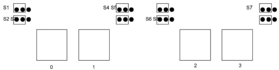
Table 192 Set the jumpers on the FIC-4BSE
| Jumper settings & description | ||
| Interface 0 | S2 | To use a 100-ohm matched resistance for data transmission, place the jumper over pins 1 and 2.To do otherwise, place the jumper over jump pins 2 and 3.See Figure 142. |
| S1 | To use a 100-ohm matched resistance for data receiving, place the jumper over jump pins 1 and 2.To do otherwise, place the jumper over jump pins 2 and 3.See Figure 142. | |
| Interface 1 | S4 | To use a 100-ohm matched resistance for data transmission, place the jumper over pins 1 and 2.To do otherwise, place the jumper over jump pins 2 and 3.See Figure 142. |
| S3 | To use a 100-ohm matched resistance for data receiving, place the jumper over jump pins 1 and 2.To do otherwise, place the jumper over jump pins 2 and 3.See Figure 142. | |
| Interface 2 | S6 | To use a 100-ohm matched resistance for data transmission, place the jumper over pins 1 and 2.To do otherwise, place the jumper over jump pins 2 and 3.See Figure 142. |
| S5 | To use a 100-ohm matched resistance for data receiving, place the jumper over jump pins 1 and 2.To do otherwise, place the jumper over jump pins 2 and 3.See Figure 142. | |
| Interface 3 | S8 | To use a 100-ohm matched resistance for data transmission, place the jumper over pins 1 and 2.To do otherwise, place the jumper over jump pins 2 and 3.See Figure 142. |
| S7 | To use a 100-ohm matched resistance for data receiving, place the jumper over jump pins 1 and 2.To do otherwise, place the jumper over jump pins 2 and 3.See Figure 142. | |
Interface LEDs
Figure 143 FIC-4BSE panel
Table 193 LED description
| LED | Description |
| LINK | Off means no link is present.On means a link is present. |
| ACT | Off means no data is being received or transmitted.Flashing means data is being received and/or transmitted. |
Interface cables and connection methods
For more information about BSE interface cables, see "BSV/BSE interface."
Serial interface module
- FIC-4SAE
- FIC-8SAE
- FIC-8ASE
- FIC-16ASE
FIC-4SAE/FIC-8SAE
Introduction
The 4-/8-port enhanced high-speed synchronous/asynchronous serial interface module (FIC-4SAE/FIC-8SAE) transmits, receives, and processes data on the synchronous/asynchronous serial interface. They support both synchronous and asynchronous modes. In synchronous mode, they support the DTE/DCE mode.
DTE and DCE
An FIC-SA module is typically connected to an external modem for dialing purposes, and an appropriate baud rate setting is required.
The synchronous serial interface can work in either DTE or DCE mode. Two directly connected devices must work as DTE and DCE. The DCE provides clock synchronization and specifies the communication rate, whereas the DTE accepts clock synchronization and communicates at the specified rate.
The router typically works as a DTE. To identify whether the equipment connected to the router is DTE or DCE, refer to the manual shipped with the equipment.
Speed and transmission segment of synchronous/asynchronous serial interface
In different operating modes, the synchronous/asynchronous serial interface supports different electric signal specifications and baud rates. In addition, the maximum signal transmission segment depends not only on the specified baud rate but also on the selected cable. The following table shows how the cable type, baud rate, and the maximum signal transmission segment relate to each other.
Table 194 Speed and transmission segment of the V.24 (RS232)/V.35 cable
| V.24 (RS232) V.35 | |||
| Baud rate (bps) | Max. transmission segment | Baud rate (bps) | Max. transmission segment |
| 2400 60 m (196.9 ft) | 2400 1250 (4101 ft) | ||
| 4800 60 m (196.9 ft) | 4800 625 m (2050.5 ft) | ||
| 9600 30 m (98.4 ft) | 9600 312 m (1023.6 ft) | ||
| 19200 30 m (98.4 ft) | 19200 156 m (511.8 ft) | ||
| 38400 20 m 65.6 ft) | 38400 78 m (255.9 ft) | ||
| 64000 20 m (65.6 ft) | 56000 60 m (196.9 ft) | ||
| 115200 10 m (32.8 ft) | 64000 50 m (164 ft) | ||
| — — 2048000 30 m (98.4 ft) | |||
NOTE:
When a V.24 cable is used, make sure the baud rate of the FIC-SA in synchronous mode does not exceed 64 Kbps.
Interface specifications
Table 195 Interface specifications
| Item | Specification | |||
| Synchronous | Asynchronous | |||
| Connector | D28 | |||
| Number of connectors | 2 (FIC-2SAE)4 (FIC-4SAE)8 (FIC-8SAE) | |||
| Interface standard and operating mode | V.24 | V.35, RS449, X.21, RS530 | RS232 | |
| DTE, DCE | DTE DCE | |||
| Min. baud rate(bps) 1200 | 1200 300 | |||
| Max. baud rate(bps) 64 k | 4.096 M | 2.048 M | 115.2 | |
| Cable | V.24 (RS232) DTE cableV.24 (RS232) DCE cableV.35 DTE cableV.35 DCE cableX.21 DTE cableX.21 DCE cableRS449 DTE cableRS449 DCE cableRS530 DTE cableRS530 DCE cable | |||
| Supported service | DDN leased lineTerminal access service | Dialup through modemBackupAsynchronous leased lineTerminal access service | ||
Interface LEDs
Figure 144 FIC-4SAE panel
Table 196 LED description
| LED | Description |
| LINK | Off means no link is present;On means a link is present. |
| ACT | Off means no data is being transmitted or received.Flashing means data is being transmitted and/or received. |
Figure 145 FIC-8SAE front panel
On the FIC-8SAE panel, each link has a LED. On means a link is present. Flashing means data is being transmitted and/or received.
Interface cables and connection methods
For more information about asynchronous serial port cables, see "Asynchronous serial ports."
FIC-8ASE/FIC-16ASE
Introduction
The 8-/16-port enhanced asynchronous serial interface module (FIC-8ASE/FIC-16ASE) transmits, receives, and processes data traffic on asynchronous serial interfaces. Each asynchronous serial interface can operate at 115.2 kbps, supporting terminal access service and asynchronous leased line. In addition, these asynchronous serial interfaces can act as the dialup access servers for the small and medium-sized ISPs to interconnect eight or 16 LANs through asynchronous dialup lines.
Interface specifications
Table 197 Interface specifications
| Item | Specification | |
| FIC-8ASE | FIC-16ASE | |
| Connector | RJ-45 | |
| Number of connectors | 8 (FIC-8ASE)16 (FIC-16ASE) | |
| Interface standard and operating mode RS232 | ||
| Cable type | AUX cableEthernet straight-through cableFIC-8ASE/FIC-16ASE dumb terminal cable | |
| Min. baud rate (bps) 300 | ||
| Max. baud rate (bps) 115.2 k | ||
| Service supported | Dialup through modemBackupTerminal access serviceAsynchronous leased line | |
Interface LEDs
Figure 146 FIC-8ASE panel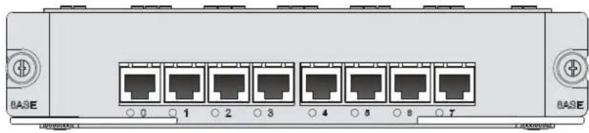
Figure 147 FIC-16ASE panel
The FIC-8ASE/FIC-16ASE has one LED for each port. On means a link is present. Off means data is being transmitted and/or received.
Interface cables and connection methods
For more information about asynchronous serial port cables, see "Asynchronous serial ports."
Voice interface module
- FIC-4FXS
- FIC-4FXO
- FIC-4E&M
- FIC-24FXS
- FIC-2VE1
- FIC-2VT1
- FIC-1VE1
- FIC-1VT1
FIC-4FXS/FIC-4FXO
Introduction
The 4-port voice subscriber circuit interface module (FIC-4FXS) processes and transmits over data communications networks voice signals for 4 regular analog phones, faxes, or AT0 loop trunks of telephone exchanges.
The 4-port voice AT0 analog trunk interface module (FIC-4FXO) processes and transmits voice signals for 4 loops of telephone exchanges over data communications networks.
Interface specifications
Table 198 Interface specifications
| Item Specification | |
| Connector | RJ-45 |
| Number of connectors | • 4 |
| Cable | • Telephone cable with ferrite core• E&M trunk cable (only for E&M modules, made on site) |
| Interface standard | • ITU Q.512-compliant subscriber circuit interface (FIC-4FXS)• ITU Q.552-compliant loop trunk interface (FIC-4FXO)• ITU K.20-compliant overcurrent protection |
| Dial-up mode | Dual-tone multifrequency (DTMF), compliant with GB3378 (Pulse dial is not available.) |
| Bandwidth | 300 Hz to 3400 Hz |
Interface LEDs
Figure 148 FIC-4FXS panel
Figure 149 FIC-4FXO panel
Table 199 LED description
| LED | Description |
| LINK | Off means no link is present.On means a link is present. |
| ACT | Off means the channel is idle.On means there is call activity. |
Interface cables and connection methods
For more information about FXS / FXO interface cables and connection methods, see "ADSL/BS/FXS/FXO/AM/FCM interface."
FIC-4E&M
Introduction
The 4-port voice E&M analog trunk interface module (FIC-4E&M) processes and transmits voice signals for 4 E&M analog trunks over data communications networks.
Interface specifications
Table 200 Interface specifications
| Item Specification | |
| Connector | RJ-45 |
| Number of connectors | • 4 |
| Cable | • Telephone cable with ferrite core• E&M trunk cable (only for E&M modules, made on site) |
| Interface standard | • ITU Q.512-compliant subscriber circuit interface (FIC-4FXS)• ITU Q.552-compliant loop trunk interface (FIC-4FXO)• ITU K.20-compliant overcurrent protection |
| Dial-up mode | Dual-tone multifrequency (DTMF), compliant with GB3378 (Pulse dial is not available.) |
| Bandwidth | 300 Hz to 3400 Hz |
Interface LEDs
Figure 150 FIC-4E&M panel
| LED | Description |
| LINK | Off means no link is present.On means a link is present. |
| ACT | Off means the channel is idle.On means there is call activity. |
Interface cables and connection methods
For more information about E&M interface cables and connection methods, see "E&M interface."
FIC-24FXS
Introduction
The 24-port voice subscriber circuit interface module (FIC-24FXS) processes and transmits voice signals over data communications networks for 24 regular analog phones, faxes, or AT0 loop trunks of telephone exchanges.
Interface specifications
Table 202 Interface specifications
| Item | Description |
| Connector 50-pin D-type female connector | |
| Interface standard FXS interface | |
| Interface rate 24 x FXS interface rate |
Interface LEDs
Table 203 LED description
| LED | Description |
| LINK | Off means no link is present.On means a link is present. |
| ACT | Off means the channel is idle.On means there is call activity. |
Figure 151 FIC-24FXS front panel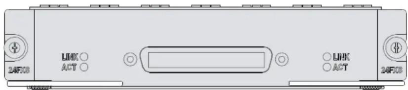
Interface cables and connection methods
For more information about 24FXS interface cables and connection methods, see "24FXS interface."
FIC-2VE1
Introduction
The 2-port E1 voice interface module (FIC-2VE1) handles dense voice signals in a VoIP system. It provides two CE1/PRI/R2 ports that provide access for a maximum of 60 channels of voice signals.
Interface specifications
Table 204 Interface specifications
| Item | Specification |
| Connector | D15 |
| Number of connectors 2 | |
| Operating mode | CE1ISDN PRI R2 |
| Interface rate 2.048 Mbps | |
| Cable | E1 75-ohm unbalanced twisted pair cableE1 120-ohm balanced twisted pair cableCoaxial connector, network connector, 75-to-120-ohm adapter (with BNC connector) |
| Supported service | R2 signalingDSS1 signalingIP FaxGeneral VoIP features in Comware |
Interface LEDs
Figure 152 FIC-2VE1 panel
Table 205 LED description
| LED | Description |
| LINK/ACT | On means carrier signal has been received.Flashing means data is being received or/and transmitted.Off means no carrier signal has been received. |
| LP/AL | On means the interface is in a loopback.Flashing means an AIS, LFA, or RAI alarm signal is present.Off means no loopback or alarm is present. |
| Note:AIS = Alarm indication signal; LFA = loss of frame alignment; RAI = Remote alarm indication | |
Interface cables and connection methods
For more information about E1 interface cables and connection methods, see "E1 interface."
FIC-2VT1
Introduction
The 2-port T1 voice interface module (FIC-2VT1) handles dense voice signals in VoIP system. It provides two CE1/PRI ports that allow access of a maximum of 48 channels of voice signals.
Interface specifications
Table 206 Interface specifications
| Item | Specification |
| Connector | RJ-45 |
| Number of connector 2 | |
| Interface standard | G.703/T1.102G.704AT&T TR 54016AT&T TR 62411ANSI T1.403 |
| Interface rate 1.544 Mbps | |
| Cable type T1 cable (100-ohm standard shielded cable) | |
| Operating mode | CT1ISDN PRI |
| Services | BackupTerminal accessISDN |
Interface LEDs
Figure 153 FIC-2VT1 panel
Table 207 LED description
| LED | Description |
| LINK/ACT | On means carrier signal has been received.Flashing means data is being received or/and transmitted.Off means no carrier signal has been received. |
| LP/AL | On means the interface is in a loopback.Flashing means an AIS, LFA, or RAI alarm signal is present.Off means no loopback or alarm is present. |
| Note:AIS = Alarm indication signal; LFA = loss of frame alignment; RAI = Remote alarm indication | |
Interface cables and connection methods
For more information about T1 interface cables and connection methods, see "T1 interface."
FIC-1VE1
Introduction
The 1-port E1 voice interface module (FIC-1VE1) handles dense voice signals in VoIP systems. It provides a CE1/PRI/R2 port that allows access to a maximum of 30 channels of voice signals.
Interface specifications
Table 208 Interface specifications
| Item | Specification |
| Connector | D15 |
| Number of connectors 1 | |
| Operating mode | CE1ISDN PRI R2 |
| Interface rate 2.048 Mbps | |
| Cable | E1 120-ohm balanced twisted pair cable75ohm-to-120ohm adapterNetwork interface connector |
| Supported service | R2 signalingDSS1 signalingIP FaxGeneral VoIP features in Comware |
Interface LEDs
Figure 154 FIC-1VE1 panel
Table 209 LED description
| LED | Description |
| LINK/ACT | On means carrier signal has been received.Flashing means data is being received or/and transmitted.Off means no carrier signal has been received. |
| LP/AL | On means the interface is in a loopback.Flashing means an AIS, LFA, or RAI alarm signal is present.Off means no loopback or alarm is present. |
| Note:AIS = Alarm indication signal; LFA = loss of frame alignment; RAI = Remote alarm indication | |
Interface cables and connection methods
For more information about E1 interface cables and connection methods, see "E1 interface."
FIC-1VT1
Introduction
The 1-port T1 voice interface module (FIC-1VT1) handles dense voice signals in VoIP systems. It provides a CT1/PRI port that allows access to a maximum of 24 channels of voice signals.
Interface specifications
Table 210 Interface specifications
| Item | Specification |
| Connector | RJ-45 |
| Number of connector 1 | |
| Interface standard | G.703/T1.102G.704AT&T TR 54016AT&T TR 62411ANSI T1.403 |
| Interface rate 1.544 Mbps | |
| Cable type T1 cable (100-ohm standard shielded cable) | |
| Operating mode | CT1ISDN PRI |
| Services | BackupTerminal accessISDN |
Interface LEDs
Figure 155 FIC-1VT1 panel
Table 211 LED description
| LED | Description |
| LINK/ACT | On means carrier signal has been received.Flashing means data is being received or/and transmitted.Off means no carrier signal has been received. |
| LP/AL | On means the interface is in a loopback.Flashing means an AIS, LFA, or RAI alarm signal is present.Off means no loopback or alarm is present. |
| Note:AIS = Alarm indication signal; LFA = loss of frame alignment; RAI = Remote alarm indication | |
Interface cables and connection methods
For more information about T1 interface cables and connection methods, see "T1 interface."
ESM/VCPM/VPM
ESMs
Enhanced service module (ESM) is installed on a multi-service module (MSC). It supports IPsec and hardware encryption and decryption and hashing operations to provide high performance and reliable encryption features.
The encryption engine is optional. On a router installed with an encryption engine, the MPU routes IP packets and implements encryption-enabled VPN, while the encryption module encrypts packets.
- ESM-ANDE
- ESM-SNDE
ESM-ANDE
Introduction
When installed with an ESM-ANDE module, the main board of your router can implement VPN with encryption provided by the ESM-ANDE module in addition to IP packet forwarding.
Interface specifications
Table 212 Interface specifications
| Item | Specification |
| Protocol supported IPsec | |
| IPsec concurrent tunnels 100 (implemented through software) | |
| Hardware algorithm | key algorithm (DES, 3DES, AES, QC5, Blowfish, Cast-128 and SkipJack)Authentication algorithm (HMAC-MD5-96, HMAC-SHA-1-96) |
Interface LEDs
The MPU on the router provides an ESM interface LED to indicate the status of the ESM-ANDE module.
Table 213 LED description
| LED | Description |
| ESMx | Green: The ANDE module is in the slot and is operating correctly.Yellow: The ANDE module is in the slot but cannot be accessed by the router. |
| Note:x means the number of the slot the ESM LED is in. | |
Installing and removing an ESM-ANDE module
For more information about installing and removing an ESM-ANDE module, see the installation guides for the HPE MSR router models.
ESM-SNDE
Introduction
The ESM-SNDE supports IPsec and hardware expedited IP data packet encryption to provide encryption with high performance and reliability.
Installed with a standard network data encryption engine (SNDE) module, the MPU on your router can implement VPN with encryption provided by the ESM-SNDE module in addition to IP packet forwarding.
Interface specifications
Table 214 Interface specifications
| Item | Specification |
| Protocol supported IPsec | |
| IPsec concurrent tunnels 100 (implemented through software) | |
| Hardware algorithm | key algorithm (DES, 3DES, AES, QC5, Blowfish, Cast-128 and SkipJack)Authentication algorithm (HMAC-MD5-96, HMAC-SHA-1-96) |
Interface LEDs
The MPU on the router provides an ESM interface LED to indicate the status of the ESM-SNDE module.
Table 215 LED description
| LED | Description |
| ESMx | Green: The SNDE module is in the slot and is operating correctly.Yellow: The SNDE module is in the slot but cannot be accessed by the router. |
| Note:x means the number of the slot the ESM LED is in. | |
Installing and removing an ESM-SNDE module
For more information about installing and removing an ESM-SNDE module, see the installation guides for the HPE MSR router models.
VCPM/VPM
- VCPM • VPM
VCPM/VPM purchase guide
- The main boards of the MSR20-40 and MSR30 series routers provide voice co-processing module (VCPM) and voice processing module (VPM) slots. They do not have VCPM and VPM modules installed when the router is shipped from the factory.
- The SIC-VE1/SIC-VT1 module does not provide any VCPM or VPM slot, and can only use the VCPM and VPM installed on the main board of the router.
- The MIM-1VE1/MIM-1VT1 module provides a VCPM and a VPM slot, and the MIM-2VE1/MIM-2VT1 module provides a VCPM and two VPM slots. Each MIM-VE1/MIM-VT1 module has a VCPM installed but has no VPM installed when it is shipped from the factory.
- The VCPM module used for the main board of the MSR20-40 and MSR30 series routers and the VCPM module that comes pre-installed on the MIM-VE1/VT1 module are different and cannot be used interchangeably.
- The VPM module used for the main board of an MSR20-40 or MSR30 series router is the same as the VPM module installed on the MIM-VE1/VT1 module.
- When you install a SIC-VE1/SIC-VT1 module on a compatible MSR20-40 and MSR30 series router, you also need to install a VCPM and VPM on the main board of the router. The number of VPMs needed depends on the number of calls. Installation should be performed by HPE Support or an authorized HPE partner.
- The MIM-VE1/VT1 module must be used with VPM installed. The number of VPMs needed depends on the number of calls.
- If you install more than one MIM-VE1/MIM-VT1 module (or one MIM-VE1/MIM-VT1 module and one SIC-VE1/SIC-VT1 module) on a compatible MSR30 series router, you need to add another VCPM on the main board of the router.
- If you install a single MIM-VE1/MIM-VT1 module on an MSR30 series router, no additional VCPM is required.
- When using an MSR router as the initiator of a three-party conference, the main board of the MSR router must have VPM installed. This is because the initiator of a three-party conference is responsible for audio mixing.
- Do not install a VCPM on the MSR20-12 router when installing a SIC-VE1/SIC-VT1 module on them. Each main board of the MSR20-12 routers provides only one VPN slot. The specifications and number of VPMs needed depend on the number of calls. Installation should be performed by HPE personnel or an authorized HPE partner.
- The multi-service module A (MSCA) of an MSR50 series router provides VCPM and VPM slots, but the multi-service module B (MSCB) provides only one VCPM slot. No VCPM and VPM slots are installed when MSR is shipped.
- Install VCPM and VPM modules on a MSCA when installing the SIC-VE1/SIC-VT1 on the MSR50 series routers. The specifications and number of VPM modules needed depend on the number of calls.
- The FIC-1VE1/FIC-1VT1 module provides one VCPM slot and one VPM slot and the FIC-2VE1/FIC-2VT1 module provides one VCPM and two VPM slots. The FIC-2VE1/FIC-2VT1 module has a VCPM installed when MSR is shipped.
- The VCPM module installed on the MSCR/MSCB of an MSR50 series router is different from the VCPM module installed on the FIC-VE1/FIC-VT1 module. Therefore, they cannot be used interchangeably.
- The FIC-VE1/FIC-VT1 is used with a VPM module installed. The specifications and number of VPM modules needed depend on the number of calls.
- The VPM modules installed on the MSCA of the MSR50 series routers are the same as the VPM modules installed on the FIC-VE1/FIC-VT1 modules.
- If you install more than two FIC-VE1/FIC-VT1 modules on an MSR50 series router, you need to add another VCPM module on the MSCA/MSCA.
VCPM
Introduction
The Voice co-processing module (VCPM) provides a transmission channel between DSP strip and system memory for voice data. This implements TDM HW exchange for each PCM data voice channel.
VCPM modules are required for voice communications of routers.
Interface specifications
Table 216 Interface specifications
| Item | Specification |
| Connector | Double-edge connector |
| Interface type PCI 2.2, EHPI | |
| Data transmission rate | Operating rate for PCI bus: 33 MHz/66 MHzMaximum bandwidth: 264 MbpsBURST transmission: Up to 1 KB of data can be transmitted once and the maximum number of bytes transmitted can be configured. |
Interface LEDs
The MPU on the router provides a VCPM interface LED to indicate the status of the VCPM module.
Table 217 LED description
| LED | Description |
| VCPMx | Green: The VCPM module is in the slot and is operating correctly.Yellow: The VCPM module is in the slot but cannot be accessed by the router. |
| Note:X means the slot number VCPM module LED is on. | |
Installing/removing a VCPM module
For more information about how to install or remove a VCPM module, see the installation guides for HPE MSR series routers.
VPM
Introduction
The Voice Processing Module (VPM) provides the following features:
- Encoding/decoding
- Echo cancellation (EC)
- Comfortable noise generation (CNG) of voices.
Interface specifications
Table 218 Interface specifications
| Item | Specification |
| Number of calls supported | 8162432 |
Installing/removing a VPM module
For more information about how to install or remove a VPM module, see the installation guides for HPE MSR series routers.
Cables and connection methods
Ethernet interface
Ethernet cable appearance and applicable models
Table 219 Ethernet cable appearance and applicable models
| Cable | Appearance | Applicable | models | |
| Ethernet cable |  1 x RJ45 < ---- > 1 x RJ45 1 x RJ45 < ---- > 1 x RJ45 | SIC-4FSWSIC-4FSW-PoEDSIC-9FSWDSIC-9FSW-PoESIC-4GSWSIC-4GSW-PoEMIM-16FSWMIM-16FSW-PoEDMIM-24FSWDMIM-24FSW-PoEFIC-16FSWFIC-16FSW-PoEDFIC-24FSWDFIC-24FSW-PoESIC-1FEASIC-1GECXMIM-16FSWXMIM-24FSWMIM-1FEMIM-2FEMIM-4FEMIM-1GBEMIM-2GBEFIC-16FSWFIC-16FSW-PoEFIC-1FEFIC-2FEFIC-4FEFIC-1GBEFIC-2GBEHMIM-8GSWHMIM-24GSWHMIM-24GSW-PoE | ||
10/100 Mbps Ethernet uses category-5 twisted pair cables, and 1000 Mbps Ethernet uses category-5 enhanced or category-6 twisted pair cables. Twisted pair cables include straight-through cables and crossover cables.
Category-5 cables provide a transmission frequency of 100 MHz for voice and data transmission. They are typically used in 100Base-T and 10Base-T networks. Category-5 cables are common Ethernet cables, which can also be used to transmit 1000 Mbps Ethernet data.
Category-5 enhanced cables feature low attenuation and crosstalk, providing higher attenuation to crosstalk ratio (ACR), less delay error and higher performance than category-5 cables. Category-5 enhanced cables are mainly used in 1000 Mbps Ethernet networks.
Category-6 cables provide a transmission frequency of 1 MHz to 250 MHz, and improve the performance on crosstalk and return loss. A fine better return loss performance is extremely important for new-generation full-duplex high-speed networks. Category-6 cables have sufficient power sum ACR (PS-ACR) when working at 200 MHz. They provide a bandwidth two times than that of category-5 enhanced cables, thus featuring a higher transmission performance. Therefore, category-6 cables are suitable for applications requiring a transmission speed of more than 1 Gbps.
The 10/100 Mbps Ethernet uses two pairs of cables, orange/white, orange, green/white and green cables, to transmit and receive data. The 1000 Mbps Ethernet uses four pairs of cables to transmit and receive data.
For the pinouts of common twisted pair cables, see the following tables. (A and B represent the two ends of a cable.)
Table 220 Straight-through cable pinouts
| Pinout No. A B | ||
| 1 | Orange/white | Orange/white |
| 2 | Orange | Orange |
| 3 | Green/white | Green/white |
| 4 | Blue | Blue |
| 5 | Blue/white | Blue/white |
| 6 | Green | Green |
| 7 | Brown/white | Brown/white |
| 8 | Brown | Brown |
Table 221 Crossover cable pinouts
| Pinout No. A B | ||
| 1 | Orange/white | Green/white |
| 2 | Orange | Green |
| 3 | Green/white | Orange/white |
| 4 | Blue | Blue |
| 5 | Blue/white | Blue/white |
| 6 | Green | Orange |
| 7 | Brown/white | Brown/white |
| 8 | Brown | Brown |
IMPORTANT:
To ensure communication quality, use the pinouts in the above tables when identifying or making the two types of Ethernet cables.
Connecting an Ethernet cable
- Connect one end of an Ethernet cable to an Ethernet interface on the module and the other end to the Ethernet interface on the peer device. Because the Ethernet interface of the module supports MDI/MDIX auto-sensing, you can use a straight-through cable or crossover cable to connect the interface.
- Check the status of the LED of the Ethernet interface after power-on. For the status of the LED, see the relevant part in this manual.
Fiber port
Appearances and applicable models of transceiver modules and optical fibers
Optical interfaces must work with SFP transceiver modules and optical fibers with LC connectors.
Table 222 Ethernet cable appearance and applicable models
| Product number | Cable | Appearance | Applicable | models |
| JD090AJD091AJD102BJD120B | SFP transceiver module |  | SIC-1FEFMIM-1POS FIC-1POS FIC-1CPOSHMIM-1POS HMIM-1CPOS MIM-1ATM-OC3 FIC-1ATM-OC3 RT-HMIM-8GSWF | |
| JD100AJD101A | 100-Mbps BIDI transceiver module |  | SIC-1FEFMIM-1POS FIC-1POS FIC-1CPOS HMIM-1POS HMIM-1CPOS MIM-1ATM-OC3 FIC-1ATM-OC3 RT-HMIM-8GSWF | |
| JD118BJD119BJD061AJD062AJD063BJD103AJD098BJD099B | SFP transceiver module |  | SIC-1GEC FIC-1GEFFIC-2GEFRT-HMIM-8GSWF | |
| JD098BJD099B | 1000-Mbps BIDI transceiver module | 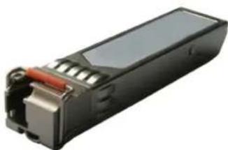 | SIC-1GECFIC-1GEFFIC-2GEFRT-HMIM-8GSWF |
100-Mbps SFP transceiver module
A 100-Mbps SFP transceiver module uses LC connectors.
Table 223 Specifications for 100-Mbps SFP transceiver modules
| Product code | Name | Center wavelength (nm) | Data rate (Mbps) | Fiber mode | Optical fiber diameter (μm) | Transmission distance | Interface specifications (dBm) | ||
| Output optical power | Receive sensitivity | Optical saturation | |||||||
| JD102B | HPE X115100M SFP LC FXTransceiver | 1310 | 155 | MMF | 50/125 | 2 km(1.24 miles) | -19 to -14 | ≤-30 | ≤-14 |
| 62.5/125 | |||||||||
| JD120B | HPE X110100M SFP LC LXTransceiver | 1310 | 155 | SMF | 9/125 | 15 km(9.32 miles) | -15 to -8 | ≤-28 | ≤-7 |
| JD090A | HPE X110100M SFP LC LH40Transceiver | 1310 | 40 km(24.86 miles) | -5 to 0 ≤-34 | ≤-9 | ||||
| JD091A | HPE X110100M SFP LC LH80Transceiver | 1550 | 80 km(49.71 miles) | -5 to 0 ≤-34 | ≤-10 | ||||
100-Mbps BIDI transceiver module
A 100-Mbps BIDI transceiver module uses LC connectors.
Table 224 Specifications for 100-Mbps BIDI transceiver modules
| Product code | Name | Center wavelength (nm) | Data rate (Mbps) | Fiber mode | Optical fiber diameter (μm) | Transmission distance | Interface specifications (dBm) | ||
| Output optical power | Receive sensitivity | Optical saturation | |||||||
| JD100A | HPE X110 100M SFP LC BX 10-U Transceiver | 1310 (TX) 1550 (RX) | 155 | SMF | 9/125 | 15 km (9.32 miles) | -15 to -8 | ≤-31 | ≤-3 |
| JD101A | HPE X110 100M SFP LC BX 10-D Transceiver | 1550 (TX) 1310 (RX) | |||||||
1000-Mbps SFP transceiver module
The 1000-Mbps SFP transceiver module uses LC connectors.
Table 225 Specifications for 1000-Mbps SFP transceiver modules
| Produ ct code | Name | Center wavele ngth (nm) | Fiber mode | Optica l fiber diam eter (μm) | Model band width (MH z*km) | Transmis sion dist ance | Interface index (dBm) | ||
| Output optical power | Receive sensitivity | Opti cal satur ation | |||||||
| JD118B | HPE X120 1G SFP LC SX Transceiver | 850 | MMF 50/125 | 500 | 550 m (180 4.46 ft) | -9.5 to 0 ≤-17 | ≤-3 | ||
| 400 | 500 m (164 0.42 ft) | ||||||||
| MMF | 62.5/12 5 | 200 | 275 m (902. 23 ft) | ||||||
| 160 | 220 m (721. 78 ft) | ||||||||
| JD119B | HPE X120 1G SFP LC LX Transceiver | 1310 | SMF | 9/125 | N/A | 10 km (6.21 miles) | -9.5 to -3 | ≤-19 | ≤-3 |
| MMF | 50/125 | 500 | 550 | ||||||
| Product code | Name | Center wavelength (nm) | Fiber mode | Optical fiber diameter (μm) | Model bandwidth (MH z*km) | Transmission distance m (180 4.46 ft) | Interface index (dBm) | ||
| Output optical power | Receive sensitivity | Optical saturation | |||||||
| 400 | |||||||||
| MMF | 62.5/125 | 500 | 550 m (180 4.46 ft) | ||||||
| JD061A | HPE X125 1G SFP LC LH40 1310nm Transceiver | 1310 | SMF | 9/125 | N/A | 40 km (24.86 miles) | -2 to +5 ≤-22 | ≤-3 | |
| JD062A | HPE X120 1G SFP LC LH40 1550nm Transceiver | 1550 | SMF | 9/125 | N/A | 40 km (24.86 miles) | -4 to +1 ≤-21 | ≤-3 | |
| JD063B | HPE X125 1G SFP LC LH70 Transceiver | 1550 | SMF | 9/125 | N/A | 70 km (43.50 miles) | -4 to +2 ≤-22 | ≤-3 | |
| JD103A | HPE X120 1G SFP LC LH100 Transceiver | 1550 | SMF | 9/125 | N/A | 100 km (62.139 miles) | 0 to +5 ≤-30 ≤-9 | ||
| JD098B | HPE X120 1G SFP LC BX 10-U Transceiver | 1310(TX) 1490(RX) | SMF | 9/125 | N/A | 10 km (6.21 miles) | -9 to -3 | ≤-18.7 | ≤-3 |
| JD099B | HPE X120 1G SFP LC BX 10-D Transceiver | 1490(TX)1310(RX) | SMF | 9/125 | N/A | 10 km (6.21 miles) | -9 to -3 | ≤-18.7 | ≤-3 |
1000-Mbps BIDI transceiver module
A 1000-Mbps BIDI transceiver module uses LC connectors.
Table 226 Specifications for 1000-Mbps BIDI transceiver modules
| Product code | Name | Center wavelength (nm) | Fiber mode | Optical fiber diameter (μm) | Transmission distance | Interface specifications (dBm) | ||
| Output optical power | Receive sensitivity | Optical saturation | ||||||
| JD098 B | HPE X120 1G SFP LC BX 10-U Transceiver | 1310 (TX) 1490 (RX) | SMF | 9/125 | 10 km (6.21 miles) | -9 to -3 | ≤-18.7 | ≤-3 |
| JD099 B | HPE X120 1G SFP LC BX 10-D Transceiver | 1490 (TX) 1310 (RX) | ||||||
Connecting an optical fiber

CAUTION:
- Never stare into an open optical Ethernet interface, because invisible rays might be emitted from the optical Ethernet interface. Cover the dust cover if no optical fiber connector is connected to the optical Ethernet interface.
To connect an optical fiber
- Insert the SFP/XFP transceiver module into the SFP/XFP interface on the interface module or service module.
- Identify the Rx and Tx ports on the SFP transceiver.
a. Plug the LC connector at one end of one fiber cable into the Rx port of the router and the LC connector at the other end into the Tx port of the peer device. b. Plug the LC connector at one end of another fiber cable into the Tx port of the router and the LC connector at the other end into the Rx port of the peer device.
- View the LINK LED after connection.
- If the LED is on, the optical fiber link is present.
- If the LED is off, no link is present. This might be because the TX and Rx ports of the optical fiber are not connected correctly. In this case, connect the optical fiber again.
E1 interface
E1 cable appearance and applicable models
Table 227 E1 cable appearance and applicable models
| Product number | Cable | Appearance | Applicable models |
| JD175AJD514AJD516A | 1-port E175-ohm cable |  1 × D15 < ---- > 2 × BNC 1 × D15 < ---- > 2 × BNC | SIC-1E1-FSIC-1EPRI MIM-1E1MIM-1E1-FMIM-2E1MIM-2E1-FFIC-1E1FIC-1E1-FFIC-2E1FIC-2E1-FHMIM-2E1SIC-1VE1MIM-1VE1MIM-2VE1FIC-1VE1FIC-2VE1HMIM-1VE1HMIM-2VE1 |
| JD509AJD517A | 1-port E1120-ohm cable |  1 × D15 < ---- > 1 × RJ45 1 × D15 < ---- > 1 × RJ45 | MIM-1E1MIM-1E1-FMIM-2E1MIM-2E1-FFIC-1E1FIC-1E1-FFIC-2E1FIC-2E1-FHMIM-2E1SIC-1VE1MIM-1VE1MIM-2VE1FIC-1VE1FIC-2VE1HMIM-1VE1HMIM-2VE1FIC-2VE1 |
| JC156AJC151AJC152A | 1-port E1120-ohm cable(2m,15m,30m)-RJ45 |  1 × RJ45 < ---- > 1 × RJ45 1 × RJ45 < ---- > 1 × RJ45 | RT-HMIM-8E1T1RT-HMIM-8E1T1-FRT-SIC-1VE1T1 |
| JD643A | 2-port E175-ohmcable |  1 × D15 < ---- > 4 × BNC 1 × D15 < ---- > 4 × BNC | SIC-2E1-F |
| JD638A | 4-port E175-ohmcable |  1 × D68 < ---- > 8 × BNC 1 × D68 < ---- > 8 × BNC | MIM-IMA-4E1FIC-IMA-4E1 |
| - | 4-port E175-ohmcable |  1 × D25 < ---- > 4 × D15 1 × D25 < ---- > 4 × D15 | MIM-4E1MIM-4E1-FFIC-4E1FIC-4E1-FHMIM-4E1HMIM-4E1-F |
| - | 4-port E1 120-ohm cable |  1 x D25 < ---- > 4 x D15 1 x D25 < ---- > 4 x D15 | MIM-4E1MIM-4E1-FFIC-4E1FIC-4E1-FHMIM-4E1HMIM-4E1-F |
| JD512AJD927A | 8-port E1 75-ohm cable |  | MIM-8E1MIM-8E1-FMIM-IMA-8E1FIC-8E1FIC-8E1-FFIC-IMA-8E1HMIM-8E1 |
| JH294A- | 1-port E1 75-ohm RJ-45 cable75-ohm adapter cable | 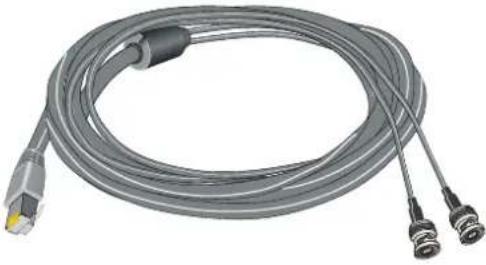  1 x BNC < ---- > 1 x BNC 1 x BNC < ---- > 1 x BNC | RT-HMIM-8E1T1RT-HMIM-8E1T1-FRT-SIC-1VE1T1Use as needed |
| - | Coaxial connector |  1 x BNC < ---- > 1 x BNC 1 x BNC < ---- > 1 x BNC | Use as needed |
| - | Impedance converter |  2 x BNC < ---- > 1 x RJ45 2 x BNC < ---- > 1 x RJ45 | Use as needed |
Dual inline package switch
The E1/E1-F/VE1 interface module provides a dual inline package (DIP) switch. The DIP switch setting defines the interface impedance and the grounding method.
Table 228 DIP switch-to-interface map
| DIP switch E1 interface | Applicable | models |
| S1 | Interface | MIM-2E1MIM-4E1MIM-4E1-FFIC-2E1FIC-4E1FIC-4E1-FHMIM-2E1HMIM-4E10HMIM-4E1-FSIC-1VE1MIM-1VE1MIM-2VE1FIC-1VE1FIC-2VE1HMIM-1VE1HMIM-2VE1 |
| S2 | Interface1 | MIM-2E1MIM-4E1MIM-4E1-FFIC-2E1FIC-4E1FIC-4E1-FHMIM-2E1HMIM-4E1HMIM-4E1-FMIM-2VE1FIC-2VE1HMIM-2VE1 |
| S3 | Interface2 | MIM-4E1MIM-4E1-FFIC-4E1-FHMIM-4E1HMIM-4E1-F |
| S4 | Interface3 | MIM-4E1MIM-4E1-FFIC-4E1-FHMIM-4E1HMIM-4E1-F |
By default, all DIP switches are On, and the E1 interface impedance is 70 ohms, as shown in the following figure:
Figure 156 Default DIP switch settings
HPE recommends that you use the DIP switch as follows:
- When the interface is connected to a 70-ohm cable, turn on switches BIT1 through 8.
- When the interface is connected to a 120-ohm cable, turn off switches BIT1 through 8.
DIP switch settings descriptions are shown in the following table:
Table 229 Description for DIP switch settings
| DIP | Description | Configuration of 75-ohm impedance | Configuration of 120-ohm impedance |
| 1BIT | 75-ohm/120-ohm selection switch | On | Off |
| 2BIT | On | Off | |
| 3BIT | On | Off | |
| 4BIT | On | Off | |
| 5BIT | On | Off | |
| 6BIT | RxRing grounding mode selection switch | Off: RxRing is grounded via capacitance.On: RxRing is grounded directly. | — |
| 7BIT | RxShield grounding mode selection switch | — | On: RxShield is grounded.Off: RxShield is not grounded. |
| 8BIT | SxShield grounding mode selection switch | — | Off: RxShield is grounded via capacitanceOn: RxShield is grounded directly. |
Connecting a 1/2/4/8-port E1 75-ohm cable (D15/D68 <----> BNC)

CAUTION:
Make sure you insert the cable into the right interface so as to avoid damages to the interface module or the chassis.
To connect the BNC connectors of the E1 75-ohm cable to the remote network device:
- Connect the D15/D68 connector of the E1 75-ohm cable to the D15/D68 interface of the interface module and fasten the bolts to fix the cable.
- The other end of the cable provides one pair or multiple pairs of 75-ohm BNC connectors. Connect the TX connectors and the RX connectors on this end to the RX connectors and the TX connectors on the remote device, respectively.
Figure 157 Connecting an E1 75-ohm cable![graph TD A["Device (75ohm E1 Port)"] --> B["1/2/4/8-port E1 75-ohm cable"] B --> C["RX"] B --> D["TX"] C --> E["Device"] D --> E style A fill:#f9f,stroke:#333 style B fill:#ccf,stroke:#333 style C fill:#cfc,stroke:#333 style D fill:#cfc,stroke:#333](/content/2026/05/818477/images/45653a3158abfcd9f989b52045c78451b082b8118b96b5a311f760ae118211a7.jpg)
To extend the cable:
- Connect each BNC connector of the E1 75-ohm cable to one end of a coaxial connector.
- Connect the remote device to the other end of the coaxial connector through an E1 75-ohm trunk cable.
Figure 158 Connecting an E1 75-ohm cable![graph LR A["E1 / E1-F (75ohm)"] --> B["1/2/4/8-port E1 75-ohm cable"] B --> C["RX"] B --> D["TX"] C --> E["Device (75ohm E1 Port)"] D --> F["Coaxial connector"] F --> G["75-ohm adapter cable"]](/content/2026/05/818477/images/d3b19eb9104ca46d426eda62101d857326bc46d57a930b8e26102e4b3d047aed.jpg)
If the impedance of the E1 interface on the remote device is 120 ohms, you must use an impedance converter to adapt the impedance.
Figure 159 Connecting an impedance converter![graph LR A["E1 / E1-F (75ohm)"] --> B["1/2/4/8-port E1 75-ohm cable"] B --> C["RX"] B --> D["TX"] C --> E["Device (120ohm E1 Port)"] D --> F["Impedance converter"] F --> G["Straight-through cable"]](/content/2026/05/818477/images/c86b5f8f4806443966b77d2bdbf2e8e8190d4ded90edac276751c2971215ae8f.jpg)
Connecting a 4-port E1 75-ohm cable (D25 <----> D15)
- Connect the D25 connector of the 4-port E1 75-ohm cable to the D25 interface of the interface module and fasten the bolts to fix the cable.
- The other end of the cable provides four D15 connectors. Connect them to the D15 interfaces on the remote device as needed.
Figure 160 Connecting a 4-port E1 75-ohm cable![graph TD A["E1 / E1-F (75ohm)"] --> B["4-port E1 75-ohm cable"] B --> C["Device (75ohm E1 Port)"] C --> D["1-port E1 75-ohm cable"] D --> E["RX"] D --> F["TX"] D --> G["RX"] style A fill:#f9f,stroke:#333 style C fill:#ccf,stroke:#333 style D fill:#cfc,stroke:#333](/content/2026/05/818477/images/18a0ce9f47579a8c6352a97ecb5e71b22fd0802e0db13e76a91289e8ce9e522a.jpg)
Connecting a 1-port E1 120-ohm cable (D15 <----> RJ45)
- Connect the D15 connector of the E1 120-ohm cable to the D15 interface on the interface module and fasten the bolts to fix the cable.
- The other end of the cable provides one or multiple RJ45 connectors. Connect them to the RJ45 interface on the remote device as needed.
Figure 161 Connecting an E1 120-ohm cable![graph TD A["Device (120ohm E1 Port)"] --> B["1-port E1 120-ohm cable"] B --> C["E1 / E1-F (120ohm)"]](/content/2026/05/818477/images/5075360aa212e14ab1161057f5f3c503ad1c461544c66e7b3e3a615678e8c90e.jpg)
Connecting a 4-port E1 120-ohm cable (D25 <----> D15)
- Connect the D25 connector of the 4-port E1 120-ohm cable to the D25 interface on the interface module and fasten the bolts to fix the cable.
- The other end of the cable provides four D15 connectors. Connect them to the D15 interface on the remote device as needed.
Figure 162 Connecting a 4-port E1 120-ohm cable![graph LR A["E1 / E1-F (120ohm)"] --> B["4-port E1 120-ohm cable"] B --> C["Device (120ohm E1 Port)"] C --> D["1-port E1 120-ohm cable"] D --> E["Device (120ohm E1 Port)"]](/content/2026/05/818477/images/855353d8eb1f8eeb6171a93d2e77266c3940ddbaffeec736093f0765c27d74a3.jpg)
T1 interface

CAUTION:
To avoid damage to the interface module or the chassis, make sure you insert the cable into the correct interface.
T1 cable appearance and applicable models
Table 230 T1 cable appearance and applicable models
| Product number | Cable | Appearance | Applicable models |
| JD518A | 1-port T1 cable (100-ohm standard shielded cable) |  | SIC-1T1-FMIM-2T1MIM-2T1-FMIM-4T1-FFIC-1T1FIC-1T1-FFIC-2T1FIC-2T1-FFIC-4T1FIC-4T1-FHMIM-2T1HMIM-4T1-FRT-SIC-1VE1T1SIC-1VE1T1SIC-1VT1MIM-1VT1MIM-2VT1FIC-1VT1FIC-2VT1HMIM-1VT1HMIM-2VT1RT-HMIM-8E1T1RT-HMIM-8E1T1-F |
| JD640A | 4-port T1 cable |  1 × D68 < ---- > 4 × RJ45 1 × D68 < ---- > 4 × RJ45 | MIM-IMA-4T1FIC-IMA-4T1 |
| JD639A | 8-port T1 cable |  1 x D68 < ---- > 8 x RJ45 1 x D68 < ---- > 8 x RJ45 | MIM-8T1MIM-8T1-FFIC-8T1FIC-8T1-FFIC-IMA-8T1 |
| - | RJ45 connector | 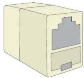 1 x RJ45 < ---- > 1 x RJ45 1 x RJ45 < ---- > 1 x RJ45 | Use as needed |
Connecting a 1-port T1 cable
The two ends of the 1-port T1 cable are RJ45 connectors. Connect one end of the cable to the T1 connector (RJ45) of the interface module and the other end of the cable to the T1 connector (RJ45) on the remote device.
Connecting a 4/8-port T1 cable
- Connect the D68 connector of the 4/8-port T1 cable to the D68 interface on the interface module and fasten the bolts to secure the cable.
- Connect the other end to the RJ45 interface on the remote device as needed.
E3/T3 interface
E3/T3 cable appearance and applicable models
Table 231 E3/T3 cable appearance and applicable models
| Product number | Cable | Appearance | Applicable models |
| JD531AJD533A | E3/T3interface cable | 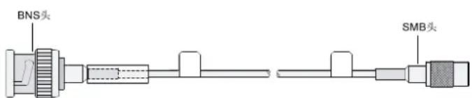 1 x BNS < ---- > 1 x SMB 1 x BNS < ---- > 1 x SMB | MIM-1CE3MIM-1CT3FIC-1CE3FIC-1CT3FIC-1AE3FIC-1AT3HMIM-1CE3HMIM-1CT3 |
Connecting the cable
- Connect the SMB connector on one end of an E3/T3 cable to the Tx port on the interface module and the other end of the cable to the Rx port on the device to be connected.
- Connect the SMB connector of another E3/T3 cable to the Rx port on the interface module and the other end of the cable to the Tx port on the device to be connected.
- Check the LINK LED on the module panel. It is off when a fault has occurred on the link and the signal is out of synchronization. In this case, check the link.
Synchronous/asynchronous serial ports
Appearance and applicable models of synchronous/asynchronous serial port cables
Table 232 Appearance and applicable models of synchronous/asynchronous serial port cables
| Product number | Cable Appearance | Applicable models | |
| JD519A | V.24DTEcable |  1 x D25 (male) < ---- > 1 x D28 1 x D25 (male) < ---- > 1 x D28 | SIC-1SAESIC-2SAESIC-4SAEMIM-2SAEMIM-4SAEMIM-8SAE |
| JD521A | V.24 DCE cable | [A]  1 x D25 (female) < ---- > 1 x D28 1 x D25 (female) < ---- > 1 x D28 | FIC-2SAE FIC-4SAE FIC-8SAE HMIM-4SAE HMIM-8SAE |
| JD523A | V.35 DTE cable | 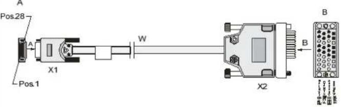 1 x D28 < ---- > 1 x D34 (male) 1 x D28 < ---- > 1 x D34 (male) | |
| JD525A | V.35 DCE cable | [A]  1 x D28 < ---- > 1 x D34 (female) 1 x D28 < ---- > 1 x D34 (female) | |
| JD527A | X.21 DTE cable |  1 x D15 (male) < ---- > 1 x D28 1 x D15 (male) < ---- > 1 x D28 | |
| JD529A | X.21 DCE cable |  1 x D15 (female) < ---- > 1 x D28 1 x D15 (female) < ---- > 1 x D28 | |
| JF825A | RS-449 DTE cable |  1 x D28 < ---- > 1 x D37 (male) 1 x D28 < ---- > 1 x D37 (male) | |
| JF826A | RS-449 DCE cable |  1 x D28 < ---- > 1 x D37 (female) 1 x D28 < ---- > 1 x D37 (female) | |
| JF827A | RS-530 DTE cable | A 1 x D25 (male) < ---- > 1 x D28 1 x D25 (male) < ---- > 1 x D28 | |
| JF828A | RS-530 DCE cable |  1 x D25 (female) < ---- > 1 x D28 1 x D25 (female) < ---- > 1 x D28 | |
Connecting the cable
- Check the port type of the peer device and choose the correct synchronous serial interface cable.
- Plug the D28 end of the synchronous serial interface cable into the D28 interface of the SAE interface module.
- If the WAN uses a DDN line, connect the cable to the port of the CSU/DSU.
- Check the LINK LED on the SAE panel.
If the LED is on, a link is present.
If the LED is off, a fault has occurred on the link and signal is out of synchronization. In this case, check the link.
Asynchronous serial ports
Appearance and applicable models of asynchronous serial port cables
Table 233 Appearance and applicable models of asynchronous serial port cables
| Product number | Cable | Appearance | Applicable models |
| JD642A | 8-port asynchronous serial port adapter cable |  1 x D60 < ---- > 8 x RJ45 (female) 1 x D60 < ---- > 8 x RJ45 (female) | SIC-8AS |
| JG263A- | 4-port asynchronous serial port adapter cableStraight-through cable |  1 x D28 < ---- > 4 x RJ45 (female) 1 x D28 < ---- > 4 x RJ45 (female) | SIC-16ASMIM-8ASEMIM-16ASEFIC-8ASEFIC-16ASEHMIM-16ASE |
| JD641A | Dumb terminal adapter cable |   1 x RJ45 (female) < ---- > 1 x RJ45 (male) 1 x RJ45 (female) < ---- > 1 x RJ45 (male) | MIM-8ASEMIM-16ASEFIC-8ASEFIC-16ASEHMIM-16ASE |
| JD508A | AUX cable |  1 x D25 & 1 x D9 < ---- > 1 x RJ45 1 x D25 & 1 x D9 < ---- > 1 x RJ45 | MIM-8ASEMIM-16ASEFIC-8ASEFIC-16ASEHMIM-16ASE |
| JD636A | Dumb terminal adapter |  1 x D25 < ---- > 1 x RJ45 1 x D25 < ---- > 1 x RJ45 | MIM-8ASEMIM-16ASEFIC-8ASEFIC-16ASEHMIM-16ASE |
Connecting a SIC-8AS/SIC-16AS interface module
- To connect the SIC-8AS interface module, connect the D60 connector of the 8-port asynchronous serial port adapter cable to the SIC-8AS interface module.
- To connect the SIC-16AS interface module, connect the D28 connector of the 4-port asynchronous serial port adapter cable to the SIC-16AS interface module, which allows up to four such cables.
Choose the cable connection type according to the remote device type:
- If the remote device connector is an RJ45 connector, connect it to the RJ45 interface of the asynchronous serial port adapter cable using a straight-through cable. The sequence is shown in the following figure:
Figure 163 Connecting a telecommunication device![graph TD A["8AS 16AS"] --> B["Central Server"] C["Asynchronous serial port adapter cable"] --> B D["StraightThrough cable"] --> B B --> E["Telecom device"]](/content/2026/05/818477/images/3ce647caffcf0e6b4bfe44b58026d0c5419849adad0e03e8a4025341fbecce86.jpg)
- If the remote device is a bank dumb terminal device:
- Connect the RJ45 connector (male) on one end of the dumb terminal cable to the RJ45 interface on the asynchronous serial port adapter cable.
- Connect the RJ45 connector (female) on the other end of the dumb terminal cable to the RJ45 interface on one end of the dumb terminal adapter using a straight-through cable.
- The other end of the dumb terminal adapter is a D25 interface and can be connected to the bank dumb terminal device. The sequence is shown in the following figure:
Figure 164 Connecting the dumb terminal device![graph LR A["8AS 16AS"] --> B["Central Node"] B --> C["Asynchronous serial port adapter cable"] B --> D["Dumb terminal adapter cable"] B --> E["Straight-through cable"] B --> F["Dumb terminal adapter"] B --> G["Bank dumb terminal device"]](/content/2026/05/818477/images/77c29470800783814143452da360018c89c4870f7ef3a09a4d29cd10371e9533.jpg)
- If the interface of the remote device is a D25/D9 interface, use the AUX cable to connect the asynchronous serial port adapter cable to the interface:
Figure 165 Connecting a modem![graph TD A["8AS 16AS"] --> B["Asynchronous serial port adapter cable"] B --> C["AUX cable"] C --> D["Modem"] B --> E["..."] B --> F["..."] B --> G["..."] B --> H["..."]](/content/2026/05/818477/images/d78f84d8adf288751a1d859f0e39ae9e7828d4609ace3acc8469da11cfd697a6.jpg)
Connecting a MIM-8ASE/MIM-16ASE/FIC-8ASE/FIC-16ASE interface module

CAUTION:
- To avoid damage to the device and the ports, do not plug or unplug the MIM-8ASE/MIM-16ASE module interface cable when the router is powered on.
- To avoid damaging the interface module or the chassis, make sure you insert the cable into the correct interface.
Choose the cable connection type according to the remote device type:
- If the remote device is a telecommunications device with an RJ45 interface, connect it to the RJ45 interface of the MIM-8ASE/MIM-16ASE/FIC-8ASE/FIC-16ASE interface module using a straight-through cable. The sequence is shown in the following figure:
Figure 166 Connecting a telecommunications device![graph TD A["8ASE"] -->|StraightThrough cable| B["Telecom device"] C["16ASE"] -->|StraightThrough cable| B B --> D["Switch"]](/content/2026/05/818477/images/61f3d9731321a41ba47969f8fb2e099b79bf97c843e3c22aad6f6f1a8b65ddb2.jpg)
- If the remote device is a bank dumb terminal device, connect the RJ45 connector (male) on one end of the dumb terminal cable to the RJ45 interface on the MIM-8ASE/MIM-16ASE/FIC-8ASE/FIC-16ASE interface module. Connect the RJ45 connector (female) on the other end of the dumb terminal cable to the RJ45 interface on one end of the dumb terminal adapter using a straight-through cable. The other end of the dumb terminal adapter is a D25 interface and can be connected to the bank dumb terminal device. The sequence is shown in the following figure:
Figure 167 Connecting a bank dumb terminal device![graph LR A["8ASE 16ASE"] --> B["Dumb terminal adapter cable"] B --> C["Straight-through cable"] C --> D["Dumb terminal adapter"] D --> E["Bank dumb terminal device"]](/content/2026/05/818477/images/1b88c1a0a72272236bdf70d4747bfc5b559562e62b281a01b172e03e863b850b.jpg)
- If the interface of the remote device is a D25/D9 interface, use the AUX cable to connect to the RJ45 interface on the MIM-8ASE/MIM-16ASE/FIC-8ASE/FIC-16ASE interface module. The sequence is shown in the following figure:
Figure 168 Connecting a modem![graph TD A["8ASE"] --> B["Modem"] C["16ASE"] --> B["Modem"] D["AUX cable"] --> B["Modem"]](/content/2026/05/818477/images/18a99b06f6408684339a8c063346c14ee9bbb327bf40b96cae6919f558ff7e55.jpg)
ADSL/BS/FXS/FXO/AM/FCM interface
Appearance and applicable models of the magnetic-core telephone cable
Table 234 Appearance and applicable models of magnetic-core telephone cable
| Cable | Appearance | Applicable models |
| Magnetic-core telephone cable |  1 × RJ11 < ---- > 1 × RJ11 1 × RJ11 < ---- > 1 × RJ11 | SIC-1ADSLSIC-1ADSL-ISIC-1BSSIC-1FXSSIC-1FXOSIC-2FXSSIC-2FXOSIC-2FXS1FXODSIC-4FXS1FXOMIM-2FXSMIM-2FXOMIM-4FXSMIM-4FXOMIM-16FXSFIC-2FXSFIC-2FXOFIC-4FXSFIC-4FXOHMIM-4FXSHMIM-4FXOHMIM-16FXS |
Connecting an ADSL/FXS/FXO interface module
- Connect one end of the magnetic-core telephone cable to the RJ11 or RJ45 interface of the interface module.
- Connect the other end of the magnetic-core telephone cable to the remote device interface.
Connecting a SIC-1BS interface module cable
- If the service provider provides an ISDN U interface cable, you must use an NT1 device for adaptation.
a. Connect one end of the magnetic-core telephone cable to the RJ45 interface of the SIC-1BS interface module. b. Connect the other end of the magnetic-core telephone cable to the S/T interface of the NT1 device. c. Connect the ISDN U interface cable to the U interface on the NT1 device.
Figure 169 Connecting the U interface cable to the SIC-1BS interface module![graph LR A["SIC-1BS"] --> B["MT"] B --> C["NT1"] C --> D["ISDN U interface cable of Service provider"] style A fill:#f9f,stroke:#333 style B fill:#ccf,stroke:#333 style C fill:#cfc,stroke:#333 style D fill:#fcc,stroke:#333](/content/2026/05/818477/images/226f758f8da4f85b83312760d18325562580fe35d25ea9f6f81bd6c59c8250e7.jpg)
- If the service provider provides an ISDN S/T interface cable, directly connect the cable to the RJ45 interface of the SIC-1BS interface module.
Figure 170 Connecting the S/T interface cable to the SIC-1BS interface module
E&M interface
E&M interface appearance and the applicable model
MIM-4E&M/FIC-4E&M modules support Bell I, II, III, V switches, and 2-wire & 4-wire voice signals.
HPE recommends that you use Bell V 4-wire voice signal to communicate with the router.
The sequence of E&M RJ-45 pins is shown in the following figure, numbered 1 to 8 in order from PIN1:
Figure 171 Sequence of RJ-45 pins
Table 235 Pinouts of E&M interface cable (Bell V 4-wire)
| E&M interface | ||
| RJ-45 Pin Signal Signal direction | ||
| 1 | — | — |
| 2 | E | IN |
| 3 | RING0 | IN |
| 4 | RING1 | OUT |
| 5 | TIP1 | OUT |
| 6 | TIP0 | IN |
| 7 | M | OUT |
| 8 | SG | |
NOTE:
The 4E&M modules cannot determine the interface types (Bell I/II/III/V), cable types (2-wire or 4-wire), and pinouts (E/M/Tx/Rx) of the peer switch. You must prepare the interface cables of the 4E&M modules according to the on-site conditions. To ensure the EMC of the router, install a ferrite core near the connector of the E&M module interface cable at the router side.
Connecting the cable
- Connect one end of the magnetic-core telephone cable to the RJ11 or RJ45 interface of the interface module.
- Connect the other end of the magnetic-core telephone cable to the remote device interface.
24FXS interface
24FXS interface cable appearance and applicable models
Table 236 24FXS interface cable appearance and applicable models
| Product number | Cable | Appearance | Applicable models |
| JG318A | 24FXS interface cable | 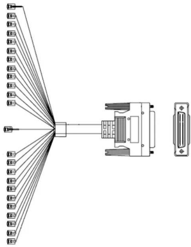 24 x RJ11 < ---- > 1 x D50 24 x RJ11 < ---- > 1 x D50 | FIC-24FXS |
Connecting the cable
- Connect the D50 interface (male) of the 24FXS interface cable to the FIC-24FXS interface module.
- Connect the other end of the 24FXS interface cable to the RJ11 interface on the remote device.
BSV/BSE interface
BSV/BSE interface cable appearance and applicable models
Table 237 BSV/BSE interface cable appearance and applicable models
| Cable | Appearance | Applicable models |
| ISDN S/T interface standard cable |  1 x RJ45 < ---- > 1 x RJ45 1 x RJ45 < ---- > 1 x RJ45 | SIC-1BSV-SIC-2BSVMIM-4BSVFIC-4BSE |
| ISDN S/T interface crossover cable |   1 x RJ45 (female) < ---- > 1 x RJ45 (male) 1 x RJ45 (female) < ---- > 1 x RJ45 (male) | SIC-1BSVSIC-2BSVMIM-4BSV |
Connecting a SIC-1BSV/SIC-2BSV/MIM-4BSV interface module cable
The BSV interface supports User and Network working modes. The BSV interface operates in User mode when connecting to an ISDN network, or operates in Network mode when connecting to TE devices such as digital telephones or BSV interfaces operating in User mode.
Choose the cable connection type according to the working mode:
- When the BSV interface operates in User mode, choose the connection method according to the type of cable provided by the service provider:
If the service provider provides an ISDN U interface cable, you must use an NT1 device for adaptation. a. Connect one end of the standard ISDN S/T interface cable to the RJ45 interface of the BSV interface module. b. Connect the other end of the standard ISDN S/T interface cable to the S/T interface of the NT1 device. c. Connect the ISDN U interface cable to the U interface on the NT1 device.
Figure 172 Connecting a service provider U interface cable to a BSV interface module![graph LR A["BSV"] --> B["NT1"] B --> C["ISDN S/T interface standard cable"] B --> D["ISDN U interface cable of service provider"]](/content/2026/05/818477/images/e93532e192bbdc0418a2aa2e94bbffe33c4142c474e2d9b98395e6d0d860d521.jpg)
If the service provider provides an ISDN S/T interface cable, directly connect the service provider cable to the BSV interface.
Figure 173 Connecting a service provider S/T interface cable to a BSV interface module
When the BSV interface operates in Network mode, you must use an ISDN S/T interface crossover cable to connect the BSV interface to a TE device. For example, a digital telephone or a BSV interface operating in User mode.
a. Connect the RJ45 connector (male) of the ISDN S/T interface crossover cable to the RJ45 interface on the BSV interface module. b. Connect the RJ45 interface (female) of the standard ISDN S/T interface cable to one end of the standard ISDN S/T interface cable. c. Connect the S/T interface on the TE device to the other end of the standard ISDN S/T interface cable.
Figure 174 Connecting a TE device to a BSV interface module![graph LR A["BSV"] --> B["ISDN S/T interface crossover cable"] B --> C["TE"] C --> D["ISDN S/T interface standard cable"] style A fill:#f9f,stroke:#333 style B fill:#ccf,stroke:#333 style C fill:#cfc,stroke:#333 style D fill:#fcc,stroke:#333](/content/2026/05/818477/images/2218b20ef2ace38d7bb52002936a0cebe319416bce6d90c42631ddcbd728effc.jpg)
Connecting a FIC-4BSE interface module cable
Choose the cable connection type according to the service provider line type:
- If the service provider provides an ISDN U interface cable, you must use an NT1 device for adaptation. a. Connect one end of the standard ISDN S/T interface cable to the RJ45 interface of the BSE interface module. b. Connect the other end of the standard ISDN S/T interface cable to the S/T interface of the NT1 device. c. Connect the ISDN U interface cable to the U interface on the NT1 device.
Figure 175 Connecting a service provider U interface cable to a BSE interface module![graph LR A["BSE"] --> B["NT1"] B --> C["ISDN S/T interface standard cable"] B --> D["ISDN U interface cable of service provider"]](/content/2026/05/818477/images/e09142842f88e8a402d11502bd39b8ad5756052fe244ea549c9818b9b881672d.jpg)
If the service provider provides an ISDN S/T interface cable, directly connect the service provider cable to the RJ45 interface on the BSE interface module.
Figure 176 Connecting a service provider S/T interface cable to a BSE interface module
G.SHDSL interface
Appearance and applicable models of the G.SHDSL interface adapter cable
Table 238 Appearance and applicable models of the G.SHDSL interface adapter cable
| Cable | Appearance | Applicable models |
| 8-wireG.SHDSLinterface cable |  1 x RJ45 (8 wires) < ---- > 2 x RJ11 (4 wire) 1 x RJ45 (8 wires) < ---- > 2 x RJ11 (4 wire) | DSIC-1SHDSL-8W |
| 4-wire Y typeG.SHDSL interface cable | 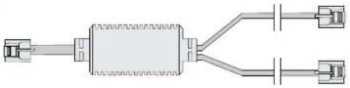 1 x RJ11 (4 wire) < ---- > 2 x RJ11 (2 wire) 1 x RJ11 (4 wire) < ---- > 2 x RJ11 (2 wire) | MIM-1SHL-4W |
| 4-wire I typeG.SHDSL interface cable |  1 x RJ11 (4 wire) < ---- > 1No RJ11 (4 wire) 1 x RJ11 (4 wire) < ---- > 1No RJ11 (4 wire) | MIM-1SHL-4W |
Connecting a DSIC-1SHDSL-8W interface module cable
- Connect the RJ45 connector on one end of the 8-wire G.SHDSL interface cable to the RJ45 interface on the DSIC-1SHDSL-8W interface module.
- The other end of the cable provides two RJ11 connectors. They can be connected to two 4-core telephone cables.
Use correct wire pairs when the DSIC-1SHDSL-8W interface module cable is operating in different modes:
- When the interface module cable is operating in dual-wire mode, use Line 0.
- When the interface module cable is operating in four-wire mode, use Line 0 and Line 1.
- When the interface module cable is operating in six-wire mode, use Line 0, Line 1, and Line 2.
The sequence of the RJ-45 connector pins is shown in Figure 177, numbered 1 to 8 in order from PIN1.
Figure 177 Sequence of RJ-45 pins
Table 239 Pinouts of DSIC-1SHDSL-8W interface module cable
| Pin | Line | Signal |
| 1 | 1 | Ring |
| 2 | 1 | Tip |
| 3 | 2 | Ring |
| 4 | 0 | Ring |
| 5 | 0 | Tip |
| 6 | 2 | Tip |
| 7 | 3 | Ring |
| 8 | 3 | Tip |
Connecting a MIM-1SHL-4W interface module cable
One end of the cable provides one RJ11 connector, the other end of the cable provides two RJ11 connectors that can be connected to two 2-core telephone cables.
To connect the 4-wire Y type G.SHDSL interface cable:
- Connect the end with only one RJ11 connector of the cable to the RJ11 interface on the MIM-1SHL-4W interface module.
- Connect the other end of the cable to the network device.
- Connect the 4-wire I type G.SHDSL interface cable as follows:
Each end of the cable provides one RJ11 connector that can be connected to one 4-core telephone cable.
- Connect one end of the cable to the RJ11 interface on the MIM-1SHL-4W interface module.
- Connect the other end of the cable to the network device.
Use correct wire pairs when the MIM-1SHL-4W interface module cable is operating in different modes:
- When the interface module cable is operating in dual-wire mode, use Line 0.
- When the interface module cable is operating in four-wire mode, use Line 0 and Line 1.
Table 240 Pinouts of the MIM-1SHL-4W interface module cable
| Pin | Line | Signal |
| 1 | 1 | Tip |
| 2 | 0 | Tip |
| 3 | 0 | Ring |
| 4 | 1 | Ring |
WLAN interface
Appearance and applicable models of the WLAN interface module antenna
Table 241 Appearance and applicable models of the WLAN interface module antenna
| Cable | Appearance | Applicable | models |
| WLAN interface module antenna |  | SIC-WLAN-b/g/nSIC-WLAN-b/g/n(NA) |
Connecting a WLAN interface module antenna
- To install an antenna, adjust the angle of the antenna to 180 degrees.
- Fasten the antenna onto the antenna connector on the interface module. Avoid over-tightening. Make sure the antenna is vertical to the ground or ceiling to achieve the optimal coverage.
3G interface
Appearance and applicable models of the SIC-3G-GSM/SIC-3G-HSPA / SIC-3G-HSPA+ interface module antenna
Table 242 Appearance and applicable models of the SIC-3G-GSM/SIC-3G-HSPA / SIC-3G-HSPA+ interface module antenna
| Product number | Cable | Appearance | Applicable models | |
| - | SIC-3G-GSM/SIC-3G-HSPA/SIC-3G-HSPA+ interface module antenna |  | SIC-3G-GSM SIC-3G-HSPA SIC-3G-HSPA + | |
| JD508A | AUX cable |  | ||
| 1 x D25 & 1 x D9 < ---- > 1 x RJ45 | ||||
Table 243 Detailed specifications for the SIC-3G-GSM/SIC-3G-HSPA / SIC-3G-HSPA+ interface module antenna
| Item | Description |
| Frequency scope 824-960 MHz/1710-2170 MHz | |
| Voltage standing wave ratio ≤ 2 | |
| Input impedance 50 Ω | |
| Gain | 1.5 |
| Polarization type Vertical | |
| Maximum input power 10 W | |
| Interface | TNC-Male |
| Lightning protection Direct current grounding | |
| Height 153 mm (6.02 in) | |
| Weight 26 g (0.92 oz) | |
| Length | None |
| Color | Black |
| Operation temperature -30 °C to 60 °C (-22°F to 140°F) | |
Connecting a SIC-3G-GSM/SIC-3G-HSPA / SIC-3G-HSPA+ interface module antenna
- To install an antenna, adjust the angle of the antenna to 180 degrees.
- Fasten the antenna onto the antenna port that has a MAIN mark. Avoid over-tightening. Make sure the antenna is vertical to the ground or ceiling to achieve the optimal coverage.
Connecting a SIC-3G-GSM/SIC-3G-HSPA / SIC-3G-HSPA+ interface debug antenna
- Connect the RJ-45 interface of the AUX cable to the Diag Port interface.
- Connect the D25/D9 connector to a peer device, which is typically a PC.
4G interface
Appearance and applicable models of the SIC-4G-LTE-V/SIC-4G-LTE-A/SIC-4G-LTE-G interface module antenna
Table 244 Appearance and applicable models of the 4G interface module antenna
| Appearance | Applicable |
 | SIC-4G-LTE-VSIC-4G-LTE-ASIC-4G-LTE-G |
Table 245 Specifications
| Item | Description |
| Frequency scope 698 to 960 MHz/1.71 to 2.7 GHz | |
| Voltage standing wave ratio 2.5 | |
| Input impedance 50 ohms | |
| Gain | 2 dB |
| Polarization type Vertical | |
| Maximum input power 5 W | |
| Interface | TNC |
| Height 21.4 cm (8.43 in) | |
| Weight 50.5 g (1.78 oz) | |
| Color | Black |
| Operation temperature -40°C to +85°C ( -40°F to +185°F ) | |
Installing a 4G interface module antenna
- Change the angle of the antenna orientation from vertical to horizontal.
- Fasten the antenna onto the antenna port that has a MAIN mark. Avoid over-tightening.
- Change the antenna orientation to vertical to achieve better signal coverage.
Installing a 4G interface debugging antenna
A 4G interface module has a Mini USB port to connect to the peer device through the USB console cable for third-party software to debug the 4G interface module. When the interface module is operating correctly, you do not need to connect the USB console cable.
To debug a 4G interface module:
- Connect the port at one end of the USB console cable to the peer device (PC).
- Connect the other end to the Mini USB port on the interface module.
Appendix A Interface module list
The full names and abbreviations of the interface modules are listed below. To simplify the descriptions in the guide, abbreviations are used to identify the interface modules.
Table 246 Interface module list
| Product code Full name Abbreviation Height | |||
| JD573B | RT-SIC-4FSW-H3 | SIC-4FSW | |
| JD574B | RT-DSIC-9FSW-H3 | DSIC-9FSW | |
| JD620A | RT-SIC-4FSW-POE-H3 | SIC-4FSW-POE | 0.5U |
| JD621A | RT-DSIC-9FSW-POE-H3 | DSIC-9FSW-POE | 0.5U |
| JF280A | RT-SIC-1FEF-H3 | SIC-1FEF | |
| JD545B | RT-SIC-1FEA-H3 | SIC-1FEA | 0.5U |
| JD572A | RT-SIC-1GEC-H3 | SIC-1GEC-H3 | 0.5U |
| JG738A | RT-SIC-1GEC-V2 | SIC-1GEC-V2 | 0.5U |
| JD634B | RT-SIC-1E1-F-V3-H3 | SIC-1E1-F | 0.5U |
| JD538A | RT-SIC-1T1-F-V2-H3 | SIC-1T1-F | 0.5U |
| JF842A | RT-SIC-2E1-F-H3 | SIC-2E1-F | 0.5U |
| JF253B | RT-SIC-EPRI-H3 | SIC-1EPRI | 0.5U |
| JG604A | RT-SIC-1EPRI-V3 | SIC-1EPRI | 0.5U |
| JF281A | RT-SIC-8AS-H3 | SIC-8AS | 0.5U |
| JG186A | RT-SIC-16AS-H3 | SIC-16AS | 0.5U |
| JD557A | RT-SIC-1SAE-H3 | SIC-1SAE | |
| JG736A | RT-SIC-2SAE | SIC-2SAE | 0.5U |
| JG737A | RT-SIC-4SAE | SIC-4SAE | 0.5U |
| JG191A | RT-DSIC-1SHDSL-8W-H3 | DSIC-1SHDSL-8W | 0.5U |
| JD537A | RT-SIC-1ADSL-H3 | SIC-1ADSL | 0.5U |
| JG056B | RT-SIC-1ADSL-I-H3 | SIC-1ADSL-I | 0.5U |
| JD571A | RT-SIC-1BS-V2-H3 | SIC-1BS | 0.5U |
| JD561A | RT-SIC-1FXS-V2-H3 | SIC-1FXS | 0.5U |
| JD560A | RT-SIC-2FXS-V2-H3 | SIC-2FXS | 0.5U |
| JD559A | RT-SIC-1FXO-V2-H3 | SIC-1FXO | 0.5U |
| JD558A | RT-SIC-2FXO-V2-H3 | SIC-2FXO | 0.5U |
| JD632A | RT-SIC-2FXS1FXO-H3 | SIC-2FXS1FXO | 0.5U |
| JG189A | RT-DSIC-4FXS1FXO-H3 | DSIC-4FXS1FXO | 0.5U |
| JD612B | RT-SIC-1BSV-H3 | SIC-1BSV | |
| JF821A | RT-SIC-2BSV-H3 | SIC-2BSV | 0.5U |
| JD575B | RT-SIC-1VE1-V2-H3 | SIC-1VE1 | 0.5U |
| JD576B | RT-SIC-1VT1-V2-H3 | SIC-1VT1 | |
| JH240A | RT-SIC-1VE1T1 | RT-SIC-1VE1T1 | |
| JF819A | RT-SIC-AP-H3 | SIC-WLAN-b/g/n | |
| JG211A | RT-SIC-AP-H3 | SIC-WLAN-b/g/n | (NA) |
| JF820A | RT-SIC-3G-GSM-H3 | SIC-3G-GSM | |
| JG187A | RT-SIC-3G-HSPA-H3 | SIC-3G-HSPA | 0.5U |
| JG929A | RT-SIC-3G-HSPA+-H3 | SIC-3G-HSPA+ | 0.5U |
| JG739A | RT-SIC-4GSW | SIC-4GSW | 0.5U |
| JG740A | RT-SIC-4GSW-POE | SIC-4GSW-POE | 0.5U |
| JG742A | RT-SIC-4G-LTE-V | SIC-4G-LTE-V | 0.5U |
| JG743A | RT-SIC-4G-LTE-A | SIC-4G-LTE-A | 0.5U |
| JG744A | RT-SIC-4G-LTE-G | SIC-4G-LTE-G | 0.5U |
| JD569A | RT-MIM-16FSW-H3 | MIM-16FSW | 1U |
| JD618A | RT-MIM-16FSW-POE-H3 | MIM-16FSW-POE | 1U |
| JF279A | RT-XMIM-16FSW-H3 | XMIM-16FSW | 1U |
| JF276A | RT-XMIM-24FSW-H3 | XMIM-24FSW | 1U |
| JD564A | RT-DMIM-24FSW-H3 | DMIM-24FSW | 1U |
| JD619A | RT-DMIM-24FSW-POE-H3 | DMIM-24FSW-POE | 1U |
| JD613A | RT-MIM-2FE-V2-H3 | MIM-2FE | 0.5U |
| JD551A | NS-MIM-4FE-H3 | MIM-4FE | 0.5U |
| JD548A | RT-MIM-2GBE-H3 | MIM-2GBE | 0.5U |
| JD624A | RT-MIM-1ATM-OC3-H3 | MIM-1ATM-OC3 | 0.5U |
| JD555B | RT-MIM-IMA-8E1(75)-H3 | MIM-IMA-8E1(75) | 0.5U |
| JD556A | RT-MIM-IMA-4T1-V2-H3 | MIM-IMA-4T1 | 0.5U |
| JG193A | RT-MIM-1POS-V2-H3 | MIM-1POS | 0.5U |
| JD544A | RT-MIM-2E1-V3-H3 | MIM-2E1 | 0.5U |
| JD550A | RT-MIM-4E1-V3-H3 | MIM-4E1 | 0.5U |
| JF257B | RT-MIM-4E1-F-V2-H3 | MIM-4E1-F | 0.5U |
| JD563A | RT-MIM-8E1(75)-H3 | MIM-8E1(75) | 0.5U |
| JF255A | RT-MIM-8E1(75)-F-H3 | MIM-8E1(75)-F | 0.5U |
| JD549A | RT-MIM-2T1-V2-H3 | MIM-2T1 | 0.5U |
| JF254B | RT-MIM-4T1-F-V2-H3 | MIM-4T1-F | 0.5U |
| JC160A | RT-MIM-8T1-H3 | MIM-8T1 | 0.5U |
| JC159A | RT-MIM-8T1-F-H3 | MIM-8T1-F | 0.5U |
| JD630A | RT-MIM-1CE3-V2-H3 | MIM-1CE3 | 0.5U |
| JD628A | RT-MIM-1CT3-V2-H3 | MIM-1CT3 | 0.5U |
| JD547A | RT-MIM-1SHL-4W-H3 | MIM-1SHL-4W | 0.5U |
| Product code Full name Abbreviation Height | |||
| JD540A | RT-MIM-2SAE-H3 | MIM-2SAE | |
| JD541A | RT-MIM-4SAE-H3 | MIM-4SAE | |
| JD552A | RT-MIM-8SAE-H3 | MIM-8SAE | |
| JF840A | RT-MIM-8ASE-H3 | MIM-8ASE | |
| JF841A | RT-MIM-16ASE-H3 | MIM-16ASE | |
| JD543A | RT-MIM-2FXO-V2-H3 | MIM-2FXO | |
| JD553A | RT-MIM-4FXS-V2-H3 | MIM-4FXS | |
| JD542A | RT-MIM-4FXO-V2-H3 | MIM-4FXO | |
| JF822A | RT-MIM-16FXS-H3 | MIM-16FXS | |
| JD539A | RT-MIM-4EM-H3 | MIM-4E&M | 0.5U |
| JF837A | RT-MIM-4BSV-H3 | MIM-4BSV | |
| JD565A | RT-MIM-1VE1-V2-H3 | MIM-1VE1 | 1U |
| JD566A | RT-MIM-1VT1-V2-H3 | MIM-1VT1 | 1U |
| JD567A | RT-MIM-2VE1-V2-H3 | MIM-2VE1 | 1U |
| JD568A | RT-MIM-2VT1-V2-H3 | MIM-2VT1 | 1U |
| JG741A | RT-HMIM-8GSW | HMIM-8GSW | 0.5U |
| JG426A | RT-HMIM-24GSW | HMIM-24GSW | 1U |
| JG427A | RT-HMIM-24GSW-PoE | HMIM-24GSW-PoE | 1U |
| JG420A | RT-HMIM-2GEE | HMIM-2GEE | 0.5U |
| JG421A | RT-HMIM-4GEE | HMIM-4GEE | 0.5U |
| JG422A | RT-HMIM-8GEE | HMIM-8GEE | 0.5U |
| JG423A | RT-HMIM-2GEF | HMIM-2GEF | 0.5U |
| JG424A | RT-HMIM-4GEF | HMIM-4GEF | 0.5U |
| JG425A | RT-HMIM-8GEF | HMIM-8GEF | 0.5U |
| JH238A | RT-HMIM-8GSWF | RT-HMIM-8GSWF | 0.5U |
| JG438A | RT-HMIM-1POS | HMIM-1POS | 0.5U |
| JG428A | RT-HMIM-1CPOS | HMIM-1CPOS | 0.5U |
| JG450A | RT-HMIM-2E1 | HMIM-2E1 | 0.5U |
| JG451A | RT-HMIM-4E1 | HMIM-4E1 | 0.5U |
| JG453A | RT-HMIM-4E1-F | HMIM-4E1-F | 0.5U |
| JG452A | RT-HMIM-8E1 | HMIM-8E1 | 0.5U |
| JG456A | RT-HMIM-2T1 | HMIM-2T1 | 0.5U |
| JG457A | RT-HMIM-4T1-F | HMIM-4T1-F | 0.5U |
| JH169A | RT-HMIM-8E1T1 | RT-HMIM-8E1T1 | 0.5U |
| JH172A | RT-HMIM-8E1T1-F | RT-HMIM-8E1T1-F | 0.5U |
| JG436A | RT-HMIM-1CE3 | HMIM-1CE3 | 0.5U |
| JG435A | RT-HMIM-1CT3 | HMIM-1CT3 | 0.5U |
| Product code Full name Abbreviation Height | |||
| JG442A | RT-HMIM-4SAE | HMIM-4SAE | |
| JG443A | RT-HMIM-8SAE | HMIM-8SAE | |
| JG445A | RT-HMIM-16ASE | HMIM-16ASE | |
| JG431A | RT-HMIM-2VE1 | HMIM-2VE1 | |
| JG429A | RT-HMIM-1VE1 | HMIM-1VE1 | |
| JG432A | RT-HMIM-2VT1 | HMIM-1VT1 | |
| JG430A | RT-HMIM-1VT1 | HMIM-1VT1 | |
| JG446A | RT-HMIM-4FXS | HMIM-4FXS | |
| JG447A | RT-HMIM-4FXO | HMIM-4FXO | |
| JG434A | RT-HMIM-16FXS | HMIM-16FXO | 1U |
| JG448A | RT-HMIM-4E&M | HMIM-4E&M | 0.5U |
| JD604A | RT-FIC-16FSW-H3 | FIC-16FSW | 1U |
| JD616A | RT-FIC-16FSW-POE-H3 | FIC-16FSW-POE | 1U |
| JD603A | RT-DFIC-24FSW-H3 | FIC-24FSW | 1U |
| JD617A | RT-DFIC-24FSW-POE-H3 | FIC-24FSW-POE | 1U |
| JD577A | RT-FIC-2FE-V2-H3 | FIC-2FE | 1U |
| JF824A | RT-FIC-4FE-H3 | FIC-4FE | 1U |
| JD583B | RT-FIC-1GBE-V2-H3 | FIC-1GBE | 1U |
| JF269B | RT-FIC-2GBE-V2-H3 | FIC-2GBE | 1U |
| JD582A | RT-FIC-1GEF-V2-H3 | FIC-1GEF | 1U |
| JF270B | RT-FIC-2GEF-V2-H3 | FIC-2GEF | 1U |
| JD622A | RT-FIC-IMA-4E1(75)-V3-H3 | FIC-IMA-4E1(75) | 1U |
| JF278B | RT-FIC-IMA-8E1(75)-V2-H3 | FIC-IMA-8E1(75) | 1U |
| JD596A | RT-FIC-1AE3-V3-H3 | FIC-1AE3 | 1U |
| JD595A | RT-FIC-1AT3-V3-H3 | FIC-1AT3 | 1U |
| JG200A | RT-FIC-IMA-8T1-V2-H3 | FIC-IMA-8T1 | 1U |
| JD633A | RT-FIC-1ATM-OC3-H3 | FIC-1ATM-OC3MM | 1U |
| JD581C | RT-FIC-1POS-V4-H3 | FIC-1POS | 1U |
| JG201A | RT-FIC-1CPOS-H3 | FIC-1CPOS | 1U |
| JD578A | RT-FIC-2E1-V3-H3 | FIC-2E1 | 1U |
| JD588A | RT-FIC-4E1-V4-H3 | FIC-4E1 | 1U |
| JD591A | RT-FIC-4E1-F-V4-H3 | FIC-4E1-F | 1U |
| JD585A | RT-FIC-8E1(75)-V3-H3 | FIC-8E1(75) | 1U |
| JD586B | RT-FIC-8T1-V2-H3 | FIC-8T1 | 1U |
| JD592A | RT-FIC-4T1-F-V3-H3 | FIC-4T1-F | 1U |
| JD625A | RT-FIC-1CE3-V3-H3 | FIC-1CE3 | 1U |
| JD629A | RT-FIC-1CT3-V3-H3 | FIC-1CT3 | 1U |
| JD589A | RT-FIC-4BSE-V2-H3 | FIC-4BSE | |
| JD584A | RT-FIC-4SAE-V2-H3 | FIC-4SAE | |
| JD580A | RT-FIC-8SAE-V2-H3 | FIC-8SAE | |
| JF260B | RT-FIC-8ASE-V2-H3 | FIC-8ASE | |
| JF265B | RT-FIC-16ASE-V2-H3 | FIC-16ASE | |
| JD594A | RT-FIC-4FXS-V3-H3 | FIC-4FXS | |
| JD593A | RT-FIC-4FXO-V3-H3 | FIC-4FXO | |
| JG197A | RT-FIC-24FXS-H3 | FIC-24FXS | |
| JD602A | RT-FIC-4EM-V2-H3 | FIC-4E&M | 1U |
| JD607A | RT-FIC-1VE1-V2-H3 | FIC-1VE1 | 1U |
| JD605A | RT-FIC-1VT1-V2-H3 | FIC-1VT1 | 1U |
| JD587A | RT-FIC-2VE1-V2-H3 | FIC-2VE1 | 1U |
| JD606A | RT-FIC-2VT1-V2-H3 | FIC-2VT1 | 1U |
| JD608A | RT-ESM-ANDE-H3 | ESM-ANDE | - |
| JD609A | RT-ESM-SNDE-H3 | ESM-SNDE | - |
| JD610A | RT-VCPM-H3 | VCPM | - |
| JD598A | RT-VPM32-H3 | VPM32 | - |
| JD599A | RT-VPM24-H3 | VPM24 | - |
| JD600A | RT-VPM16-H3 | VPM16 | - |
| JD601A | RT-VPM8-H3 | VPM8 | - |
| JG417A | RT-VPM2-128 | VPM2-128 | - |
| JG418A | RT-VPM2-256 | VPM2-256 | - |
| JG419A | RT-VPM2-512 | VPM2-512 | - |
| JG415A | RT-HMIM-Adapter | RT-HMIM-Adapter | 0.5U |
| JG416A | RT-HMIM-Adapter-H | RT-HMIM-Adapter-H | 1U |
1U
1U
1U
1U
1U
1U
1U
1U
Appendix B Purchase guide
This appendix introduces the types of interface modules that each model of HPE MSR routers can accommodate. In the tables, "Yes" means "Supported" and "No" means "Not supported."
SIC/DSIC purchase guide
NOTE:
- MSR50(MPU-G2), MSR4000, MSR900, and MSR930 routers do not support the installation of SIC/DSIC interface modules.
- A PoE interface module provides PoE features only when it is installed on a PoE device.
Table 247 SIC/DSIC options
| Product code | Type | 20-1 X | 20-20/ 20-21 | 20-40 | 30-10 | 30-11E /30-11 F | 30-16 | 30-20/ 30-40/ 30-60 | 50-40 / 50-60 + MPU F |
| JD573B | SIC-4FS W | Yes | Yes | Yes in Slot 2 and Slot 4 | Yes in Slot 2 | Yes in Slot 2 | Yes in Slot 2 and Slot 4 | Yes in Slot 2 and Slot 4 | Yes in Slot 2 and Slot 4 |
| JD574B | DSIC-9F SW | Yes | No | Yes in Slot 2 and Slot 4 | No | No | Yes in Slot 2 and Slot 4 | Yes in Slot 2 and Slot 4 | Yes in Slot 2 and Slot 4 |
| JD620A | SIC-4FS W-POE | Yes | Yes | Yes in Slot 2 and Slot 4 | Yes in Slot 2 | Yes in Slot 2 | Yes in Slot 2 and Slot 4 | Yes in Slot 2 and Slot 4 | Yes in Slot 2 and Slot 4 |
| JD621A | DSIC-9F SW-POE | Yes | No | Yes in Slot 2 and Slot 4 | No | No | Yes in Slot 2 and Slot 4 | Yes in Slot 2 and Slot 4 | Yes in Slot 2 and Slot 4 |
| JF280A | SIC-1FEF | Yes | Yes | Yes in Slot 2 and Slot 4 | Yes in Slot 2 | Yes in Slot 2 | Yes in Slot 2 and Slot 4 | Yes in Slot 2 and Slot 4 | Yes in Slot 2 and Slot 4 |
| JD545B | SIC-1FE A | Yes | Yes | Yes in Slot 2 and Slot 4 | Yes in Slot 2 | Yes in Slot 2 | Yes in Slot 2 and Slot 4 | Yes in Slot 2 and Slot 4 | Yes in Slot 2 and Slot 4 |
| JD572A | SIC-1GE C-H3 | Yes | Yes | Yes in Slot 2 and Slot 4 | Yes in Slot 2 | Yes in Slot 2 | Yes in Slot 2 and Slot 4 | Yes in Slot 2 and Slot 4 | Yes in Slot 2 and Slot 4 |
| JD634B | SIC-1E1-F | Yes | Yes | Yes | Yes | Yes | Yes | Yes | Yes |
| JD538A | SIC-1T1-F | Yes | Yes | Yes | Yes | Yes in Slot 1 | Yes | Yes | Yes |
| JF842A | SIC-2E1-F | Yes | Yes | Yes | Yes | Yes | Yes | Yes | Yes |
| JF253B | SIC-EPRI | Yes | Yes | Yes | Yes in Slot 1 Yes | Yes | Yes | Yes | |
| JF281A | SIC-8AS | Yes | Yes | Yes | Yes | Yes | Yes | Yes | Yes |
| JG186A | SIC-16AS | Yes | Yes | Yes | Yes | Yes | Yes | Yes | Yes |
| JD557A | SIC-1SA E | Yes | Yes | Yes | Yes | Yes | Yes | Yes | Yes |
| JG191A | DSIC-1SHDSL-8 W | Yes | No | Yes | No | No | Yes | Yes | Yes |
| JD537A | SIC-1AD SL | Yes | Yes | Yes in Slot 2 and Slot 4 | Yes in Slot 2 | Yes in Slot 2 | Yes in Slot 2 and Slot 4 | Yes in Slot 2 and Slot 4 | Yes |
| JG056B | SIC-1AD SL-I | Yes | Yes | Yes in Slot 2 and Slot 4 | Yes in Slot 2 | Yes in Slot 2 | Yes in Slot 2 and Slot 4 | Yes in Slot 2 and Slot 4 | Yes in Slot 2 and Slot 4 |
| JD571A | SIC-1BS | Yes | Yes | Yes | Yes | Yes in Slot 1 | Yes | Yes | Yes |
| JD561A | SIC-1FX S | Yes | Yes | Yes | Yes | Yes | Yes | Yes | Yes |
| JD560A | SIC-2FX S | Yes | Yes | Yes | Yes | Yes | Yes | Yes | Yes |
| JD559A | SIC-1FX O | Yes | Yes | Yes | Yes | Yes | Yes | Yes | Yes |
| JD558A | SIC-2FX O | Yes | Yes | Yes | Yes | Yes | Yes | Yes | Yes |
| JD632A | SIC-2 FXS1FX O | Yes | Yes | Yes | Yes | Yes | Yes | Yes | Yes |
| JG189A | DSIC-4FXS1FXO | Yes | Yes | Yes | Yes | Yes | Yes | Yes | Yes |
| JF821A | SIC-2BS V | Yes | Yes | Yes | Yes | Yes in Slot 1 | Yes | Yes | Yes |
| JD575B | SIC-1VE1 | Yes | No | Yes | Yes in Slot 1 | No | Yes | Yes | Yes |
| JD576B | SIC-1VT1 | Yes | No Yes | Yes in Slot 1 | No | Yes | Yes | Yes | |
| JH240A | RT-SIC-1 VE1T1 | Yes | No | Yes | Yes in Slot 1 | No | Yes | Yes | Yes |
| JF820A | SIC-3G-G SM | Yes | Yes | Yes in Slot 2 and Slot 4 | Yes in Slot 2 | Yes in Slot 2 | Yes in Slot 2 and Slot 4 | Yes in Slot 2 and Slot 4 | Yes in Slot 2 and Slot 4 |
| JG187A | SIC-3G-H SPA | Yes | Yes | Yes in Slot 2 and Slot 4 | Yes in Slot 2 | Yes in Slot 2 | Yes in Slot 2 and Slot 4 | Yes in Slot 2 and Slot 4 | Yes in Slot 2 and Slot 4 |
| JG929A | SIC-3G-H SPA+ | Yes | Yes | Yes in Slot 2 and Slot 4 | Yes in Slot 2 | Yes in Slot 2 | Yes in Slot 2 and Slot 4 | Yes in Slot 2 and Slot 4 | Yes in Slot 2 and Slot 4 |
| JF819A | SIC-WLA N-b/g/n | Yes | Yes | Yes in Slot 2 and Slot 4 | Yes in Slot 2 | Yes in Slot 2 | Yes in Slot 2 and Slot 4 | Yes in Slot 2 and Slot 4 | Yes in Slot 2 and Slot 4 |
| Product code | Type | 1002-4 | 1003-8/1003-8S | 2003 | 2004-24/48 | 3012 | 3024 | 3044 | 3064 |
| JF280A | SIC-1FEF | Yes in Slot 2 | Yes in Slot 2 and Slot 3 | Yes in Slot 2 and Slot 3 | Yes in Slot 2 and Slot 4 | Yes | Yes in Slot 2 and Slot 4 | Yes in Slot 2 and Slot 4 | Yes in Slot 2 and Slot 4 |
| JG738A | SIC-1GEC-V2 | Yes in Slot 2 | Yes in Slot 2 | Yes in Slot 2 | Yes in Slot 2 | Yes | Yes in Slot 2 and Slot 4 | Yes in Slot 2 and Slot 4 | Yes in Slot 2 and Slot 4 |
| JD545B | SIC-1FEA | Yes in Slot 2 | Yes in Slot 2 and Slot 3 | Yes in Slot 2 and Slot 3 | Yes in Slot 2 and Slot 4 | Yes | Yes in Slot 2 and Slot 4 | Yes in Slot 2 and Slot 4 | Yes in Slot 2 and Slot 4 |
| JD573B | SIC-4FSW | Yes in Slot 2 | Yes in Slot 2 and Slot 3 | Yes in Slot 2 and Slot 3 | Yes in Slot 2 and Slot 4 | Yes | Yes in Slot 2 and Slot 4 | Yes in Slot 2 and Slot 4 | Yes in Slot 2 and Slot 4 |
| JD620A | DSIC-4FSWP | Yes in Slot 2 | Yes in Slot 2 and Slot 3 | Yes in Slot 2 and Slot 3 | Yes in Slot 2 and Slot 4 | Yes | Yes in Slot 2 and Slot 4 | Yes in Slot 2 and Slot 4 | Yes in Slot 2 and Slot 4 |
| JD574B | DSIC-9FSW | Yes in Slot 2 | Yes in Slot 2 | Yes in Slot 2 | No | No | Yes in Slot 2 and Slot 4 | Yes in Slot 2 and Slot 4 | Yes in Slot 2 and Slot 4 |
| JD621A | DSIC-9 FSWP | Yes in Slot 2 | Yes in Slot 2 | Yes in Slot 2 | No | No | Yes in Slot 2 and Slot 4 | Yes in Slot 2 and Slot 4 | Yes in Slot 2 and Slot 4 |
| JD537A | SIC-1A DSL | Yes in Slot 2 | Yes in Slot 2 and Slot 3 | Yes in Slot 2 and Slot 3 | Yes in Slot 2 and Slot 4 | Yes | Yes in Slot 2 and Slot 4 | Yes in Slot 2 and Slot 4 | Yes in Slot 2 and Slot 4 |
| JG056B | SIC-1A DSL-I | Yes in Slot 2 | Yes in Slot 2 and Slot 3 | Yes in Slot 2 and Slot 3 | Yes in Slot 2 and Slot 4 | Yes | Yes in Slot 2 and Slot 4 | Yes in Slot 2 and Slot 4 | Yes in Slot 2 and Slot 4 |
| JG191A | DSIC-1 SHDSL -8W | Yes in Slot 2 | Yes in Slot 2 | Yes in Slot 2 | No | No | Yes in Slot 2 and Slot 4 | Yes in Slot 2 and Slot 4 | Yes in Slot 2 and Slot 4 |
| JD634B | SIC-1E 1-F | Yes | Yes | Yes | Yes | Yes | Yes | Yes | Yes |
| JF842A | SIC-2E 1-F | Yes | Yes | Yes | Yes | Yes | Yes | Yes | Yes |
| JD538A | SIC-1T 1-F | Yes | Yes | Yes | Yes | Yes | Yes | Yes | Yes |
| JG604A | SIC-1E PRI | Yes | Yes | Yes | Yes | Yes | Yes | Yes | Yes |
| JD557A | SIC-1S AE | Yes | Yes | Yes in Slot 2 and Slot 3 | Yes | Yes | Yes | Yes | |
| JG736A | SIC-2S AE | Yes | Yes | Yes in Slot 2 and Slot 3 | Yes | Yes | Yes | Yes | |
| JG737A | SIC-4S AE | Yes | Yes | Yes in Slot 2 and Slot 3 | Yes | Yes | Yes | Yes | |
| JF281A | SIC-8A S | Yes | Yes | Yes | Yes | Yes | Yes | Yes | Yes |
| JG186A | SIC-16 AS | Yes | Yes | Yes | Yes | Yes | Yes | Yes | Yes |
| JD571A | SIC-1B S | Yes | Yes | Yes | Yes | Yes | Yes | Yes | Yes |
| JD561A | SIC-1F XS | Yes | Yes | Yes | Yes | Yes | Yes | Yes | Yes |
| JD560A | SIC-2F XS | Yes | Yes | Yes | Yes | Yes | Yes | Yes | Yes |
| JD559A | SIC-1F XO | Yes | Yes | Yes | Yes | Yes | Yes | Yes | Yes |
| JD558A | SIC-2FXO | Yes | Yes | Yes | Yes | Yes | Yes | Yes | Yes |
| JD632A | SIC-2FXS1FXO | Yes | Yes | Yes | Yes | Yes | Yes | Yes | Yes |
| JG189A | DSIC-4FXS1FXO | Yes in Slot 2 | Yes in Slot 2 | Yes in Slot 2 | No | No | Yes in Slot 2 and Slot 4 | Yes in Slot 2 and Slot 4 | Yes in Slot 2 and Slot 4 |
| JD612B | SIC-1BSV | Yes | Yes | Yes | Yes | Yes | Yes | Yes | Yes |
| JF821A | SIC-2BSV | Yes | Yes | Yes | Yes | Yes | Yes | Yes | Yes |
| JD575B | SIC-1VE1 | No | No | No | No | Yes | Yes | Yes | Yes |
| JD576B | SIC-1VT1 | No | No | No | No | Yes | Yes | Yes | Yes |
| JH240A | RT-SIC-1VE1T1 | No | No | No | No | Yes | Yes | Yes | Yes |
| JG187A | SIC-3G-HSPA | Yes in Slot 2 | Yes in Slot 2 and Slot 3 | Yes in Slot 2 and Slot 3 | Yes in Slot 2 and Slot 4 | Yes | Yes in Slot 2 and Slot 4 | Yes in Slot 2 and Slot 4 | Yes in Slot 2 and Slot 4 |
| JG929A | SIC-3G-HSPA+ | Yes in Slot 2 | Yes in Slot 2 and Slot 3 | Yes in Slot 2 and Slot 3 | Yes in Slot 2 and Slot 4 | Yes | Yes in Slot 2 and Slot 4 | Yes in Slot 2 and Slot 4 | Yes in Slot 2 and Slot 4 |
| JG739A | SIC-4GSW | Yes in Slot 2 | Yes in Slot 2 | Yes in Slot 2 | Yes in Slot 2 | Yes | Yes in Slot 2 and Slot 4 | Yes in Slot 2 and Slot 4 | Yes in Slot 2 and Slot 4 |
| JG740A | SIC-4GSWP | Yes in Slot 2 | Yes in Slot 2 | Yes in Slot 2 | Yes in Slot 2 | Yes | Yes in Slot 2 and Slot 4 | Yes in Slot 2 and Slot 4 | Yes in Slot 2 and Slot 4 |
| JG743A | SIC4G-LTE-A | Yes in Slot 2 | Yes in Slot 2 and Slot 3 | Yes in Slot 2 and Slot 3 | Yes in Slot 2 and Slot 4 | Yes | Yes in Slot 2 and Slot 4 | Yes in Slot 2 and Slot 4 | Yes in Slot 2 and Slot 4 |
| JG742A | SIC4G-LTE-V | Yes in Slot 2 | Yes in Slot 2 and Slot 3 | Yes in Slot 2 and Slot 3 | Yes in Slot 2 and Slot 4 | Yes | Yes in Slot 2 and Slot 4 | Yes in Slot 2 and Slot 4 | Yes in Slot 2 and Slot 4 |
| JG744A | SIC4G-LTE-G | Yes in Slot 2 | Yes in Slot 2 and Slot 3 | Yes in Slot 2 and Slot 3 | Yes in Slot 2 and Slot 4 | Yes | Yes in Slot 2 and Slot 4 | Yes in Slot 2 and Slot 4 | Yes in Slot 2 and Slot 4 |
MIM/XMIM/DMIM purchase guide
NOTE:
- Only MSR30 routers support the installation of the MIM/XMIM/DMIM interface modules.
- A PoE interface module provides PoE features only when it is installed on a PoE device.
Table 248 MIM/XMIM/DMIM options
| Product code | Type 30-10 | 30-11E/30-11F/30-16 | 30-20 | 30-40/30-60 | |
| JD569A | MIM-16FSW | Yes | Yes | Yes | |
| JD618A | MIM-16FSW-POE | Yes | Yes | Yes | |
| JF279A | XMIM-16FSW | Yes | Yes | No | |
| JF276A | XMIM-24FSW | Yes | Yes | No | |
| JD564A | DMIM-24FSW | No | No | No | |
| JD619A | DMIM-24FSW-POE | No | No | No | |
| JD613A | MIM-2FE | Yes | Yes | Yes | |
| JD551A | MIM-4FE | Yes | Yes | Yes | |
| JD548A | MIM-2GBE | Yes | Yes | Yes | |
| JD624A | MIM-1ATM-OC3 | Yes | Yes | Yes | |
| JD555B | MIM-IMA-8E1(75) | Yes | Yes | Yes | |
| JD556A | MIM-IMA-4T1 | Yes | Yes | Yes | |
| JG193A | MIM-1POS | Yes | Yes | Yes | |
| JD544A | MIM-2E1 | Yes | Yes | Yes | |
| JD550A | MIM-4E1 | Yes | Yes | Yes | |
| JF257B | MIM-4E1-F | Yes | Yes | Yes | Yes |
| JD563A | MIM-8E1(75) | Yes | Yes | Yes | |
| JF255A | MIM-8E1(75)-F | Yes | Yes | Yes | Yes |
| JD549A | MIM-2T1 | Yes | Yes | Yes | |
| JF254B | MIM-4T1-F | Yes | Yes | Yes | Yes |
| JC160A | MIM-8T1 | Yes | Yes | Yes | |
| JC159A | MIM-8T1-F | Yes | Yes | Yes | |
| JD630A | MIM-1CE3 | Yes | Yes | Yes | |
| JD628A | MIM-1CT3 | Yes | Yes | Yes | |
| JD547A | MIM-1SHL-4W | Yes | Yes | Yes | |
| JD540A | MIM-2SAE | Yes | Yes | Yes | |
| JD541A | MIM-4SAE | Yes | Yes | Yes | |
| JD552A | MIM-8SAE | Yes | Yes | Yes | |
| JF840A | MIM-8ASE | Yes | Yes | Yes | |
| JF841A | MIM-16ASE | Yes | Yes | Yes | |
| JD543A | MIM-2FXO | Yes | Yes | Yes | |
| JD553A | MIM-4FXS | Yes | Yes | Yes | |
| JD542A | MIM-4FXO | Yes | Yes | Yes | |
| JF822A | MIM-16FXS | Yes | Yes | Yes | |
| JD539A | MIM-4E&M | Yes | Yes | Yes | |
| JF837A | MIM-4BSV | Yes | Yes | Yes | |
| JD565A | MIM-1VE1 | Yes | Yes | Yes | |
| JD566A | MIM-1VT1 | Yes | Yes | Yes | |
| JD567A | MIM-2VE1 | Yes | Yes | Yes | |
| JD568A | MIM-2VT1 | Yes | Yes | Yes | |
HMIM purchase guide
NOTE:
- Only MSR3000, MSR4000 routers support the installation of the HMIM interface modules.
- A PoE interface module provides PoE features only when it is installed on a PoE device.
Table 249 HMIM options
| Product code | Type | 3012 | 3024 | 3044 | 3064 | 4060 | 4080 |
| JG741A | HMIM-8GSW | Yes | Yes | Yes | Yes in Slot 5, Slot 6, Slot 8, Slot 9, and Slot 10 | Yes | Yes in Slot 1, Slot 2, Slot 5, Slot 6, Slot 7, and Slot 8 |
| JG426A | HMIM-24GSW | Yes | Yes | Yes | Yes | Yes | Yes |
| JG427A | HMIM-24GSW-POE | Yes | Yes | Yes | Yes | Yes | Yes |
| JG420A | HMIM-2GE E | Yes | Yes | Yes | Yes | Yes | Yes |
| JG421A | HMIM-4GE E | Yes | Yes | Yes | Yes | Yes | Yes |
| JG422A | HMIM-8GE E | Yes | Yes | Yes | Yes | Yes | Yes |
| JG423A | HMIM-2GE F | Yes | Yes | Yes | Yes | Yes | Yes |
| JG424A | HMIM-4GE F | Yes | Yes | Yes | Yes | Yes | Yes |
| Product code | Type | 3012 | 3024 | 3044 | 3064 | 4060 | |
| JG425A | HMIM-8GE F | Yes | Yes | Yes | Yes | Yes | Yes |
| JH238A | RT-HMIM- 8GSWF | Yes | Yes | Yes | Yes in Slot 5, Slot 6, Slot 8, Slot 9, and Slot 10 | Yes | Yes in Slot 1, Slot 2, Slot 5, Slot 6, Slot 7, and Slot 8 |
| JG438A | HMIM-1PO S | Yes | Yes | Yes | Yes | Yes | Yes |
| JG428A | HMIM-1CP OS | Yes | Yes | Yes | Yes | Yes | Yes |
| JG450A | HMIM-2E1 | Yes | Yes | Yes | Yes | Yes | |
| JG451A | HMIM-4E1 | Yes | Yes | Yes | Yes | Yes | |
| JG453A | HMIM-4E1-F | Yes | Yes | Yes | Yes | Yes | Yes |
| JG452A | HMIM-8E1 | Yes | Yes | Yes | Yes | Yes | |
| JG456A | HMIM-2T1 | Yes | Yes | Yes | Yes | Yes | |
| JG457A | HMIM-4T1-F | Yes | Yes | Yes | Yes | Yes | Yes |
| JH169A | RT-HMIM- 8E1T1 | Yes | Yes | Yes | Yes | Yes | Yes |
| JH172A | RT-HMIM- 8E1T1-F | Yes | Yes | Yes | Yes | Yes | Yes |
| JG436A | HMIM-1CE 3 | Yes | Yes | Yes | Yes | Yes | Yes |
| JG435A | HMIM-1CT 3 | Yes | Yes | Yes | Yes | Yes | Yes |
| JG442A | HMIM-4SA E | Yes | Yes | Yes | Yes | Yes | Yes |
| JG443A | HMIM-8SA E | Yes | Yes | Yes | Yes | Yes | Yes |
| JG445A | HMIM-16A SE | Yes | Yes | Yes | Yes | Yes | Yes |
| JG431A | HMIM-2VE 1 | Yes | Yes | Yes | Yes | Yes | Yes |
| JG429A | HMIM-1VE 1 | Yes | Yes | Yes | Yes | Yes | Yes |
| JG432A | HMIM-2VT 1 | Yes | Yes | Yes | Yes | Yes | Yes |
| JG430A | HMIM-1VT 1 | Yes | Yes | Yes | Yes | Yes | Yes |
| JG434A | HMIM-16F XS | Yes | Yes | Yes | Yes | Yes | Yes |
| JG446A | HMIM-4FX S | Yes | Yes | Yes | Yes | Yes | Yes |
4080
Yes
Yes
Yes
Yes
| Product code | Type | 3012 | 3024 | 3044 | 3064 | 4060 | ||
| JG447A | HMIM-4FX O | Yes | Yes | Yes | Yes | Yes | Yes | |
| JG448A | HMIM-4E&M | Yes | Yes | Yes | Yes | Yes | Yes |
4080
FIC/DFIC purchase guide
NOTE:
- Only MSR50 routers support the installation of the FIC/DFIC interface modules.
- A PoE interface module provides PoE features only when it is installed on a PoE device.
Table 250 FIC/DFIC options
| Product code | Type 50-40/ 50-60 | MPUF 50-40/ 50-60 | MPU-G2 | |
| JD604A | FIC-16FSW | Yes | Yes | |
| JD616A | FIC-16FSW-POE | Yes | Yes | |
| JD603A | DFIC-24FSW | Yes | Yes | |
| JD617A | DFIC-24FSW-POE | Yes | Yes | |
| JD577A | FIC-2FE | Yes | Yes | |
| JF824A | FIC-4FE | Yes | Yes | |
| JD583B | FIC-1GBE | Yes | Yes | |
| JF269B | FIC-2GBE | Yes | Yes | |
| JD582A | FIC-1GEF | Yes | Yes | |
| JF270B | FIC-2GEF | Yes | Yes | |
| JD622A | FIC-IMA-4E1(75) | Yes | Yes | |
| JF278B | FIC-IMA-8E1(75) | Yes | Yes | |
| JD596A | FIC-1AE3 | Yes | Yes | |
| JD595A | FIC-1AT3 | Yes | Yes | |
| JG200A | FIC-IMA-8T1 | Yes | Yes | |
| JD633A | FIC-1ATM-OC3MM | Yes | Yes | |
| JD581C | FIC-1POS | Yes | Yes | |
| JG201A | FIC-1CPOS | Yes | Yes | |
| JD578A | FIC-2E1 | Yes | Yes | |
| JD588A | FIC-4E1 | Yes | Yes | |
| JD591A | FIC-4E1-F | Yes | Yes |
| Product code Type 50-40/ 50-60 MPUF 50-40/ 50-60 MPU-G2 | |||
| JD585A | FIC-8E1(75) | Yes | Yes |
| JD586B | FIC-8T1 | Yes | Yes |
| JD592A | FIC-4T1-F | Yes | Yes |
| JD625A | FIC-1CE3 | Yes | Yes |
| JD629A | FIC-1CT3 | Yes | Yes |
| JD589A | FIC-4BSE | Yes | Yes |
| JD584A | FIC-4SAE | Yes | Yes |
| JD580A | FIC-8SAE | Yes | Yes |
| JF260B | FIC-8ASE | Yes | Yes |
| JF265B | FIC-16ASE | Yes | Yes |
| JD594A | FIC-4FXS | Yes | Yes |
| JD593A | FIC-4FXO | Yes | Yes |
| JD602A | FIC-4E&M | Yes | Yes |
| JD607A | FIC-1VE1 | Yes | Yes |
| JD605A | FIC-1VT1 | Yes | Yes |
| JD587A | FIC-2VE1 | Yes | Yes |
| JD606A | FIC-2VT1 | Yes | Yes |
ESM/VPM/VCPM purchase guide
Table 251 ESM/VPM/VCPM options
| Product code | Type | 900 | 20-1 0/20 -11/ 20-1 3 | 20-1 2 | 20-2 0/ 20-2 1 | 20-4 0 | 30-1 1E/ 30-1 1F | 30-1 0 | 30-1 6 | 30-2 0/30 -40/ 30-6 0 | 50-4 0/ 50-6 0 + MP UF + MSCA | 50-40/ 50-60 + MPU-G 2 + MSCB |
| JD608A | ESM-AN DE | No | No | No | Yes | Yes | Yes | Yes | Yes | Yes | Yes | Yes |
| JD609A | ESM-SN DE | No | No | No | Yes | Yes | Yes | Yes | Yes | Yes | Yes | Yes |
| JD610A | VCPM | No | No | No | No | Yes | No | No | Yes | Yes | Yes | Yes |
| JD598A | VPM32 | No | No | Yes | No | Yes | No | Yes | Yes | Yes | Yes | No |
| JD599A | VPM24 | No | No | Yes | No | Yes | No | Yes | Yes | Yes | Yes | No |
| JD600A | VPM16 | No | No | Yes | No | Yes | No | Yes | Yes | Yes | ||
| JD601A | VPM8 | No | No | Yes | No | Yes | No | Yes | Yes | Yes |
Yes No
Yes No
| Product code | Type | 930 | 2003 | 3012 | 3024 | 3044 | 3064 | 4060 | 4080 |
| JG419A | VPM2 | 512 | No | Yes | Yes | Yes | Yes | Yes | |
| JG418A | VPM2 | 256 | No | Yes | Yes | Yes | Yes | Yes | |
| JG417A | VPM2 | 128 | No | Yes | Yes | Yes | Yes | Yes |
Yes Yes
Yes Yes
Yes Yes
Index
Numerics
3G interface module
SIC-3G-GSM, 31
SIC-3G-HSPA, 33, 34
4G interface module
SIC-4G-LTE-A, 37
SIC-4G-LTE-G, 37
SIC-4G-LTE-V, 36
A
antenna
SIC-3G-GSM, 32
SIC-3G-HSPA, 34, 35
SIC-4G-LTE-A, 39
SIC-4G-LTE-V, 37
asynchronous interface
FIC-4SAE, 118
FIC-8SAE, 118
ATM interface module
FIC-1AE3, 104
FIC-1AT3, 105
FIC-1ATM-OC3, 106
FIC-IMA-4E1, 102
FIC-IMA-8E1, 102
FIC-IMA-8T1, 103
MIM-1ATM-OC3, 45
MIM-IMA-4T1, 47
MIM-IMA-8E1, 46
C
cable
24FXS interface, 163
3G interface, 169
4G interface, 170
ADSL interface, 160
AM interface, 160
asynchronous serial port, 152
BS interface, 160
BSE interface, 164
BSV interface, 164
E&M interface, 161
E1 interface, 141
E3 interface, 152
Ethernet interface, 134
FCM interface, 160
fiber port, 136
FXO interface, 160
FXS interface, 160
G.SHDSL interface, 166
synchronous serial port, 152
T1 interface, 149
T3 interface, 152
WLAN interface, 168
connection method
24FXS interface, 163
3G interface, 169
4G interface, 170
ADSL interface, 160
AM interface, 160
asynchronous serial port, 152
BS interface, 160
BSE interface, 164
BSV interface, 164
DFIC-24FSW, 98
DFIC-24FSW-PoE, 98
DMIM-24FSW, 43
DMIM-24FSW-PoE, 43
DSIC-1SHDSL-8W, 16
DSIC-4FXS1FXO, 23
DSIC-9FSW, 2
DSIC-9FSW-PoE, 2
E&M interface, 161
E1 interface, 141
E3 interface, 152
Ethernet interface, 134
FCM interface, 160
fiber port, 136
FIC-16ASE, 121
FIC-16FSW, 98
FIC-16FSW-PoE, 98
FIC-1AE3, 105
FIC-1AT3, 105
FIC-1ATM-OC3, 106
FIC-1CE3, 114
FIC-1CPOS, 109
FIC-1CT3, 116
FIC-1GBE, 100
FIC-1GEF, 101
FIC-1POS, 107
FIC-1VE1, 127
FIC-1VT1, 129
FIC-24FXS, 124
FIC-2E1, 111
FIC-2FE, 99
FIC-2GBE, 100
FIC-2GEF, 101
FIC-2VE1, 125
FIC-2VT1, 126
FIC-4BSE, 118
FIC-4E&M, 123
FIC-4E1, 111
FIC-4E1-F, 111
FIC-4FE, 99
FIC-4FX, 123
FIC-4FXO, 123
FIC-4SAE, 120
FIC-4T1-F, 113
FIC-8ASE, 121
FIC-8E1, 112
FIC-8SAE, 120
FIC-IMA-4E1, 103
FIC-IMA-8E1, 103
FIC-IMA-8T1, 104
FXO interface, 160
FXS interface, 160
G.SHDSL interface, 166
HMIM-16ASE, 88
HMIM-16FXS, 89
HMIM-1CE3, 85
HMIM-1CPOS, 77
HMIM-1CT3, 86
HMIM-1POS, 76
HMIM-1VE1, 92
HMIM-1VT1, 93
HMIM-24GSW, 72
HMIM-24GSW-PoE, 72
HMIM-2E1, 79
HMIM-2E1T1, 84
HMIM-2E1T1-F, 84
HMIM-2GEE, 74
HMIM-2GEF, 75
HMIM-2T1, 81
HMIM-2VE1, 90
HMIM-4E&M, 95
HMIM-4E1, 79
HMIM-4E1-F, 79
HMIM-4E1T1, 84
HMIM-4E1T1-F, 84
HMIM-4FXO, 94
HMIM-4FXS, 94
HMIM-4GEE, 74
HMIM-4GEF, 75
HMIM-4SAE, 87
HMIM-4T1-F, 81
HMIM-8E1, 80
HMIM-8E1T1, 84
HMIM-8E1T1-F, 84
HMIM-8GEE, 74
HMIM-8GEF, 75
HMIM-8GSW, 72
HMIM-8GSWF, 73
HMIM-8SAE, 87
MIM-16ASE, 61
MIM-16FSW, 43
MIM-16FSW-PoE, 43
MIM-16FXS, 62
MIM-1ATM-OC3, 46
MIM-1CE3, 56
MIM-1CT3, 57
MIM-1POS, 49
MIM-1SHL-4W, 58
MIM-1VE1, 66
MIM-1VT1, 68
MIM-2E1, 51
MIM-2FE, 44
MIM-2FXO, 65
MIM-2GBE, 45
MIM-2SAE, 60
MIM-2T1, 53
MIM-2VE1, 69
MIM-2VT1, 70
MIM-4BSV, 64
MIM-4E&M, 65
MIM-4E1, 51
MIM-4E1-F, 51
MIM-4FE, 44
MIM-4FXO, 65
MIM-4FXS, 65
MIM-4SAE, 60
MIM-4T1-F, 53
MIM-8ASE, 61
MIM-8E1, 52
MIM-8E1-F, 52
MIM-8SAE, 60
MIM-8T1, 55
MIM-8T1-F, 55
MIM-IMA-4T1, 48
MIM-IMA-8E1, 47
SIC-16AS, 13
SIC-1ADSL, 17
SIC-1ADSL-I, 19
SIC-1BS, 20
SIC-1BSV, 25
SIC-1E1-F, 8
SIC-1EPRI, 10
SIC-1FEA, 4
SIC-1FEF, 5
SIC-1FXO, 22
SIC-1FXS, 22
SIC-1GEC, 6
SIC-1SAE, 15
SIC-1T1-F, 11
SIC-1VE1, 26
SIC-1VE1T1, 28
SIC-1VT1, 27
SIC-2BSV, 25
SIC-2E1-F, 9
SIC-2FXO, 22
SIC-2FXS, 22
SIC-2FXS1FXO, 22
SIC-2SAE, 15
SIC-3G-GSM, 32
SIC-3G-HSPA, 34, 35
SIC-4FSW, 2
SIC-4FSW-PoE, 2
SIC-4GSW, 3
SIC-4GSW-POE, 3
SIC-4SAE, 15
SIC-8AS, 12
SIC-EPRI, 10
SIC-WLAN-b/g/n, 31
SIC-WLAN-b/g/n(NA), 31
synchronous serial port, 152
T1 interface, 149
T3 interface, 152
WLAN interface, 168
XMIM-16FSW, 41
XMIM-24FSW, 41
CPOS (SDH/SONET) interface module
FIC-1CPOS, 108
HMIM-1CPOS, 76
D
DCE
FIC-4SAE, 118
FIC-8SAE, 118
DFIC
Ethernet switching module, 96
DMIM
Ethernet switching module, 40
DSIC
Ethernet switching module, 1
voice interface module, 20
XDSL interface module, 15
DTE
FIC-4SAE, 118
FIC-8SAE, 118
E
E1 cable
applicable interface module, 141
E1/T1 interface module
FIC-2E1, 109
FIC-4E1, 109
FIC-4E1-F, 109
FIC-4T1-F, 112
FIC-8E1, 111
HMIM-2E1, 78
HMIM-2T1, 80
HMIM-4E1, 78
HMIM-4E1-F, 78
HMIM-4T1-F, 80
HMIM-8E1, 79
MIM-2E1, 49
MIM-2T1, 52
MIM-4E1, 49
MIM-4E1-F, 49
MIM-4T1-F, 52
MIM-8E1, 51
MIM-8E1-F, 51
MIM-8T1, 53
MIM-8T1-F, 53
SIC-1E1-F, 7
SIC-1EPRI, 9
SIC-1T1-F, 10
SIC-2E1-F, 8
SIC-EPRI, 9
E3/T3 interface module
FIC-1CE3, 113
FIC-1CT3, 114
HMIM-1CE3, 84
HMIM-1CT3, 85
MIM-1CE3, 55
MIM-1CT3, 56
ESM
ESM-ANDE, 130
ESM-SNDE, 131
Ethernet interface module
FIC-1GBE, 99
FIC-1GEF, 100
FIC-2FE, 98
FIC-2GBE, 99
FIC-2GEF, 100
FIC-4FE, 98
HMIM-2E1T1, 81
HMIM-2E1T1-F, 81
HMIM-2GEE, 73
HMIM-2GEF, 74
HMIM-4E1T1, 81
HMIM-4E1T1-F, 81
HMIM-4GEE, 73
HMIM-4GEF, 74
HMIM-8E1T1, 81
HMIM-8E1T1-F, 81
HMIM-8GEE, 73
HMIM-8GEF, 74
MIM-2FE, 43
MIM-2GBE, 44
MIM-4FE, 43
SIC-1FEA, 4
SIC-1FEF, 4
SIC-1GEC, 5
Ethernet interface switching module
HMIM-24GSW, 71
HMIM-24GSW-PoE, 71
HMIM-8GSW, 71
HMIM-8GSWF, 72
Ethernet switching module
DFIC-24FSW, 96
DFIC-24FSW-PoE, 96
DMIM-24FSW, 41
DMIM-24FSW-PoE, 41
DSIC-9FSW, 1
DSIC-9FSW-PoE, 1
FIC-16FSW, 96
FIC-16FSW-PoE, 96
MIM-16FSW, 41
MIM-16FSW-PoE, 41
SIC-4FSW, 1
SIC-4FSW-PoE, 1
SIC-4GSW, 2
SIC-4GSW-POE, 2
XMIM-16FSW, 40
XMIM-24FSW, 40
F
fiber port
FIC-1ATM-OC3, 106
FIC-1CPOS, 109
FIC-1GBE, 100
FIC-1GEF, 101
FIC-1POS, 107
FIC-2GBE, 100
FIC-2GEF, 101
HMIM-1CPOS, 77
HMIM-1POS, 76
HMIM-8GSWF, 73
MIM-1ATM-OC3, 46
MIM-1POS, 49
SIC-1FEF, 5
FIC
ATM interface module, 101
CPOS (SDH/SONET) interface module, 108
E1/T1 interface module, 109
E3/T3 interface module, 113
Ethernet interface module, 98
Ethernet switching module, 96
ISDN BRI interface module, 116
POS (SDH/SONET) interface module, 107
serial interface module, 118
voice interface module, 121
H
HMIM
CPOS (SDH/SONET) interface module, 76
E1/T1 interface module, 77
E3/T3 interface module, 84
Ethernet interface module, 73
Ethernet interface switching module, 71
POS (SDH/SONET) interface module, 75
serial interface module, 86
voice interface module, 88
|
installation
ESM-ANDE, 130
ESM-SNDE, 131
VCPM, 133, 133
installing a SIM card
SIC-3G-GSM, 32
SIC-3G-HSPA, 34, 35
SIC-4G-LTE-A, 39
SIC-4G-LTE-G, 39
SIC-4G-LTE-V, 37
interface
DFIC-24FSW, 96
DFIC-24FSW-PoE, 96
DMIM-24FSW, 41
DMIM-24FSW-PoE, 41
DSIC-1SHDSL-8W, 15
DSIC-4FXS1FXO, 23
DSIC-9FSW, 1
DSIC-9FSW-PoE, 1
ESM-ANDE, 130
ESM-SNDE, 131
FIC-16ASE, 120
FIC-16FSW, 96
FIC-16FSW-PoE, 96
FIC-1AE3, 104
FIC-1AT3, 105
FIC-1ATM-OC3, 106
FIC-1CE3, 114
FIC-1CPOS, 108
FIC-1CT3, 115
FIC-1GBE, 100
FIC-1GEF, 101
FIC-1POS, 107
FIC-1VE1, 127
FIC-1VT1, 128
FIC-24FXS, 124
FIC-2E1, 110
FIC-2FE, 98
FIC-2GBE, 100
FIC-2GEF, 101
FIC-2VE1, 124
FIC-2VT1, 126
FIC-4BSE, 116
FIC-4E&M, 123
FIC-4E1, 110
FIC-4E1-F, 110
FIC-4FE, 98
FIC-4FX, 122
FIC-4FXO, 122
FIC-4SAE, 119
FIC-4T1-F, 112
FIC-8ASE, 120
FIC-8E1, 111
FIC-8SAE, 119
FIC-IMA-4E1, 102
FIC-IMA-8E1, 102
FIC-IMA-8T1, 103
HMIM-16ASE, 88
HMIM-16FXS, 89
HMIM-1CE3, 84
HMIM-1CPOS, 76
HMIM-1CT3, 85
HMIM-1POS, 75
HMIM-1VE1, 92
HMIM-1VT1, 93
HMIM-24GSW, 71
HMIM-24GSW-PoE, 71
HMIM-2E1, 78
HMIM-2E1T1, 83
HMIM-2E1T1-F, 83
HMIM-2GEE, 73
HMIM-2GEF, 74
HMIM-2T1, 80
HMIM-2VE1, 90
HMIM-4E&M, 95
HMIM-4E1, 78
HMIM-4E1-F, 78
HMIM-4E1T1, 83
HMIM-4E1T1-F, 83
HMIM-4FXO, 94
HMIM-4FXS, 94
HMIM-4GEE, 73
HMIM-4GEF, 74
HMIM-4SAE, 86
HMIM-4T1-F, 80
HMIM-8E1, 79
HMIM-8E1T1, 83
HMIM-8E1T1-F, 83
HMIM-8GEE, 73
HMIM-8GEF, 74
HMIM-8GSW, 71
HMIM-8GSWF, 72
HMIM-8SAE, 86
MIM-16ASE, 60
MIM-16FSW, 41
MIM-16FSW-PoE, 41
MIM-16FXS, 62
MIM-1ATM-OC3, 45
MIM-1CE3, 55
MIM-1CT3, 56
MIM-1POS, 48
MIM-1SHL-4W, 58
MIM-1VE1, 66
MIM-1VT1, 67
MIM-2E1, 49
MIM-2FE, 43
MIM-2FXO, 64
MIM-2GBE, 44
MIM-2SAE, 59
MIM-2T1, 52
MIM-2VE1, 68
MIM-2VT1, 69
MIM-4BSV, 63
MIM-4E&M, 65
MIM-4E1, 49
MIM-4E1-F, 49
MIM-4FE, 43
MIM-4FXO, 64
MIM-4FXS, 64
MIM-4SAE, 59
MIM-4T1-F, 52
MIM-8ASE, 60
MIM-8E1, 51
MIM-8E1-F, 51
MIM-8SAE, 59
MIM-8T1, 54
MIM-8T1-F, 54
MIM-IMA-4T1, 47
MIM-IMA-8E1, 46
SIC-16AS, 13
SIC-1ADSL, 17
SIC-1ADSL-I, 18
SIC-1BS, 19
SIC-1BSV, 24
SIC-1E1-F, 7
SIC-1EPRI, 9
SIC-1FEA, 4
SIC-1FEF, 5
SIC-1FXO, 21
SIC-1FXS, 21
SIC-1GEC, 5
SIC-1SAE, 14
SIC-1T1-F, 10
SIC-1VE1, 25
SIC-1VE1T1, 27
SIC-1VT1, 26
SIC-2BSV, 24
SIC-2E1-F, 8
SIC-2FXO, 21
SIC-2FXS, 21
SIC-2FXS1FXO, 22
SIC-2SAE, 14
SIC-3G-GSM, 31
SIC-3G-HSPA, 33, 34
SIC-4FSW, 1
SIC-4FSW-PoE, 1
SIC-4G-LTE-A, 38
SIC-4G-LTE-G, 38
SIC-4G-LTE-V, 36
SIC-4GSW, 3
SIC-4GSW-POE, 3
SIC-4SAE, 14
SIC-8AS, 12
SIC-EPRI, 9
SIC-WLAN-b/g/n, 30
SIC-WLAN-b/g/n(NA), 30
VCPM, 133
VPM, 133
XMIM-16FSW, 40
XMIM-24FSW, 40
interface cable
DFIC, 96
DFIC-24FSW, 98
DFIC-24FSW-PoE, 98
DMIM-24FSW, 43
DMIM-24FSW-PoE, 43
DSIC-1SHDSL-8W, 16
DSIC-4FXS1FXO, 23
DSIC-9FSW, 2
DSIC-9FSW-PoE, 2
FIC, 96
FIC-16ASE, 121
FIC-16FSW, 98
FIC-16FSW-PoE, 98
FIC-1AE3, 105
FIC-1AT3, 105
FIC-1CE3, 114
FIC-1CT3, 116
FIC-1VE1, 127
FIC-1VT1, 129
FIC-24FXS, 124
FIC-2E1, 111
FIC-2FE, 99
FIC-2VE1, 125
FIC-2VT1, 126
FIC-4BSE, 118
FIC-4E&M, 123
FIC-4E1, 111
FIC-4E1-F, 111
FIC-4FE, 99
FIC-4FX, 123
FIC-4FXO, 123
FIC-4SAE, 120
FIC-4T1-F, 113
FIC-8ASE, 121
FIC-8E1, 112
FIC-8SAE, 120
FIC-IMA-4E1, 103
FIC-IMA-8E1, 103
FIC-IMA-8T1, 104
HMIM-16ASE, 88
HMIM-16FXS, 89
HMIM-1CE3, 85
HMIM-1CT3, 86
HMIM-1VE1, 92
HMIM-1VT1, 93
HMIM-24GSW, 72
HMIM-24GSW-PoE, 72
HMIM-2E1, 79
HMIM-2E1T1, 84
HMIM-2E1T1-F, 84
HMIM-2GEE, 74
HMIM-2GEF, 75
HMIM-2T1, 81
HMIM-2VE1, 90
HMIM-4E&M, 95
HMIM-4E1, 79
HMIM-4E1-F, 79
HMIM-4E1T1, 84
HMIM-4E1T1-F, 84
HMIM-4FXO, 94
HMIM-4FXS, 94
HMIM-4GEE, 74
HMIM-4GEF, 75
HMIM-4SAE, 87
HMIM-4T1-F, 81
HMIM-8E1, 80
HMIM-8E1T1, 84
HMIM-8E1T1-F, 84
HMIM-8GEE, 74
HMIM-8GEF, 75
HMIM-8GSW, 72
HMIM-8SAE, 87
MIM-16ASE, 61
MIM-16FSW, 43
MIM-16FSW-PoE, 43
MIM-16FXS, 62
MIM-1CE3, 56
MIM-1CT3, 57
MIM-1SHL-4W, 58
MIM-1VE1, 66
MIM-1VT1, 68
MIM-2E1, 51
MIM-2FE, 44
MIM-2FXO, 65
MIM-2GBE, 45
MIM-2SAE, 60
MIM-2T1, 53
MIM-2VE1, 69
MIM-2VT1, 70
MIM-4BSV, 64
MIM-4E&M, 65
MIM-4E1, 51
MIM-4E1-F, 51
MIM-4FE, 44
MIM-4FXO, 65
MIM-4FXS, 65
MIM-4SAE, 60
MIM-4T1-F, 53
MIM-8ASE, 61
MIM-8E1, 52
MIM-8E1-F, 52
MIM-8SAE, 60
MIM-8T1, 55
MIM-8T1-F, 55
MIM-IMA-4T1, 48
MIM-IMA-8E1, 47
SIC-16AS, 13
SIC-1ADSL, 17
SIC-1ADSL-I, 19
SIC-1BS, 20
SIC-1BSV, 25
SIC-1E1-F, 8
SIC-1EPRI, 10
SIC-1FEA, 4
SIC-1FXO, 22
SIC-1FXS, 22
SIC-1GEC, 6
SIC-1SAE, 15
SIC-1T1-F, 11
SIC-1VE1, 26
SIC-1VE1T1, 28
SIC-1VT1, 27
SIC-2BSV, 25
SIC-2E1-F, 9
SIC-2FXO, 22
SIC-2FXS, 22
SIC-2FXS1FXO, 22
SIC-2SAE, 15
SIC-3G-GSM, 32
SIC-3G-HSPA, 34, 35
SIC-4FSW, 2
SIC-4FSW-PoE, 2
SIC-4G-LTE-G, 39
SIC-4G-LTE-V, 37
SIC-4GSW, 3
SIC-4GSW-POE, 3
SIC-4SAE, 15
SIC-8AS, 12
SIC-EPRI, 10
SIC-WLAN-b/g/n, 31
SIC-WLAN-b/g/n(NA), 31
XMIM-16FSW, 41
XMIM-24FSW, 41
interface mode switchover
FIC-1CPOS, 109
interface module
cable, 134
connection method, 134
DMIM, 40
DSIC, 1
ESM, 130, 130
HMIM, 71
list, 172
MIM, 40
SIC, 1
VCPM, 130, 131, 132
VPM, 130, 131, 133
XMIM, 40
Introduction
DFIC-24FSW, 96
DFIC-24FSW-PoE, 96
DMIM-24FSW, 41
DMIM-24FSW-PoE, 41
DSIC-1SHDSL-8W, 15
DSIC-4FXS1FXO, 23
DSIC-9FSW, 1
DSIC-9FSW-PoE, 1
ESM-ANDE, 130
ESM-SNDE, 131
FIC-16ASE, 120
FIC-16FSW, 96
FIC-16FSW-PoE, 96
FIC-1AE3, 104
FIC-1AT3, 105
FIC-1ATM-OC3, 106
FIC-1CE3, 113
FIC-1CPOS, 108
FIC-1CT3, 114
FIC-1GBE, 99
FIC-1GEF, 100
FIC-1POS, 107
FIC-1VE1, 127
FIC-1VT1, 128
FIC-24FXS, 124
FIC-2E1, 109
FIC-2FE, 98
FIC-2GBE, 99
FIC-2GEF, 100
FIC-2VE1, 124
FIC-2VT1, 125
FIC-4BSE, 116
FIC-4E&M, 123
FIC-4E1, 109
FIC-4E1-F, 109
FIC-4FE, 98
FIC-4FX, 122
FIC-4FXO, 122
FIC-4SAE, 118
FIC-4T1-F, 112
FIC-8ASE, 120
FIC-8E1, 111
FIC-8SAE, 118
FIC-IMA-4E1, 102
FIC-IMA-8E1, 102
FIC-IMA-8T1, 103
HMIM-16ASE, 88
HMIM-16FXS, 89
HMIM-1CE3, 84
HMIM-1CPOS, 76
HMIM-1CT3, 85
HMIM-1POS, 75
HMIM-1VE1, 92
HMIM-1VT1, 93
HMIM-24GSW, 71
HMIM-24GSW-PoE, 71
HMIM-2E1, 78
HMIM-2E1T1, 81
HMIM-2E1T1-F, 81
HMIM-2GEE, 73
HMIM-2GEF, 74
HMIM-2T1, 80
HMIM-2VE1, 90
HMIM-4E&M, 95
HMIM-4E1, 78
HMIM-4E1-F, 78
HMIM-4E1T1, 81
HMIM-4E1T1-F, 81
HMIM-4FXO, 94
HMIM-4FXS, 94
HMIM-4GEE, 73
HMIM-4GEF, 74
HMIM-4SAE, 86
HMIM-4T1-F, 80
HMIM-8E1, 79
HMIM-8E1T1, 81
HMIM-8E1T1-F, 81
HMIM-8GEE, 73
HMIM-8GEF, 74
HMIM-8GSW, 71
HMIM-8GSWF, 72
HMIM-8SAE, 86
MIM-16ASE, 60
MIM-16FSW, 41
MIM-16FSW-PoE, 41
MIM-16FXS, 62
MIM-1ATM-OC3, 45
MIM-1CE3, 55
MIM-1CT3, 56
MIM-1POS, 48
MIM-1SHL-4W, 57
MIM-1VE1, 66
MIM-1VT1, 67
MIM-2E1, 49
MIM-2FXO, 64
MIM-2GBE, 44
MIM-2SAE, 59
MIM-2T1, 52
MIM-2VE1, 68
MIM-2VT1, 69
MIM-4BSV, 62
MIM-4E&M, 65
MIM-4E1, 49
MIM-4E1-F, 49
MIM-4FXO, 64
MIM-4FXS, 64
MIM-4SAE, 59
MIM-4T1-F, 52
MIM-8ASE, 60
MIM-8E1, 51
MIM-8E1-F, 51
MIM-8SAE, 59
MIM-8T1, 53
MIM-8T1-F, 53
MIM-IMA-4T1, 47
MIM-IMA-8E1, 46
SIC-16AS, 13
SIC-1ADSL, 16
SIC-1ADSL-I, 18
SIC-1BS, 19
SIC-1BSV, 23
SIC-1E1-F, 7
SIC-1EPRI, 9
SIC-1FEA, 4
SIC-1FEF, 4
SIC-1FXO, 20
SIC-1FXS, 20
SIC-1GEC, 5
SIC-1SAE, 14
SIC-1T1-F, 10
SIC-1VE1, 25
SIC-1VE1T1, 27
SIC-1VT1, 26
SIC-2BSV, 23
SIC-2E1-F, 8
SIC-2FXO, 20
SIC-2FXS, 20
SIC-2FXS1FXO, 22
SIC-2SAE, 14
SIC-3G-GSM, 31
SIC-3G-HSPA, 33, 34
SIC-4FSW, 1
SIC-4FSW-PoE, 1
SIC-4GSW, 2
SIC-4GSW-POE, 2
SIC-4SAE, 14
SIC-8AS, 12
SIC-EPRI, 9
SIC-WLAN-b/g/n, 30
SIC-WLAN-b/g/n(NA), 30, 31
VCPM, 132
VPM, 133
XMIM-16FSW, 40
XMIM-24FSW, 40
ISDN BRI interface module
FIC-4BSE, 116
SIC-1BS, 19
J
jumper setting
FIC-4BSE, 116
L
LED
DMIM-24FSW, 42
DMIM-24FSW-PoE, 42
DSIC-1SHDSL-8W, 16
DSIC-4FXS1FXO, 23
ESM-ANDE, 130
ESM-SNDE, 131
FIC-16ASE, 121
FIC-1AE3, 104
FIC-1AT3, 105
FIC-1ATM-OC3, 106
FIC-1CE3, 114
FIC-1CPOS, 108
FIC-1CT3, 115
FIC-1GBE, 100
FIC-1GEF, 101
FIC-1POS, 107
FIC-1VE1, 127
FIC-1VT1, 128
FIC-24FXS, 124
FIC-2E1, 110
FIC-2FE, 99
FIC-2GBE, 100
FIC-2GEF, 101
FIC-2VE1, 125
FIC-2VT1, 126
FIC-4BSE, 117
FIC-4E&M, 123
FIC-4E1, 110
FIC-4E1-F, 110
FIC-4FE, 99
FIC-4FX, 122
FIC-4FXO, 122
FIC-4SAE, 120
FIC-4T1-F, 113
FIC-8ASE, 121
FIC-8E1, 112
FIC-8SAE, 120
FIC-IMA-4E1, 102
FIC-IMA-8E1, 102
FIC-IMA-8T1, 103
HMIM-16ASE, 88
HMIM-16FXS, 89
HMIM-1CE3, 84
HMIM-1CPOS, 77
HMIM-1CT3, 86
HMIM-1POS, 76
HMIM-1VE1, 92
HMIM-1VT1, 93
HMIM-24GSW, 71
HMIM-24GSW-PoE, 71
HMIM-2E1, 78
HMIM-2E1T1, 83
HMIM-2E1T1-F, 83
HMIM-2GEE, 73
HMIM-2GEF, 74
HMIM-2T1, 81
HMIM-2VE1, 90
HMIM-4E&M, 95
HMIM-4E1, 78
HMIM-4E1-F, 78
HMIM-4E1T1, 83
HMIM-4E1T1-F, 83
HMIM-4FXO, 94
HMIM-4FXS, 94
HMIM-4GEE, 73
HMIM-4GEF, 74
HMIM-4SAE, 87
HMIM-4T1-F, 81
HMIM-8E1, 80
HMIM-8E1T1, 83
HMIM-8E1T1-F, 83
HMIM-8GEE, 73
HMIM-8GEF, 74
HMIM-8GSW, 71
HMIM-8GSWF, 72
HMIM-8SAE, 87
MIM-16ASE, 61
MIM-16FSW, 42
MIM-16FSW-PoE, 42
MIM-16FXS, 62
MIM-1ATM-OC3, 45
MIM-1CE3, 56
MIM-1CT3, 57
MIM-1POS, 48
MIM-1SHL-4W, 58
MIM-1VE1, 66
MIM-1VT1, 67
MIM-2E1, 50
MIM-2FE, 43
MIM-2FXO, 64
MIM-2GBE, 44
MIM-2SAE, 59
MIM-2T1, 53
MIM-2VE1, 68
MIM-2VT1, 69
MIM-4BSV, 63
MIM-4E&M, 65
MIM-4E1, 50
MIM-4E1-F, 50
MIM-4FE, 43
MIM-4FXO, 64
MIM-4FXS, 64
MIM-4SAE, 59
MIM-4T1-F, 53
MIM-8ASE, 61
MIM-8E1, 51
MIM-8E1-F, 51
MIM-8SAE, 59
MIM-8T1, 54
MIM-8T1-F, 54
MIM-IMA-4T1, 47
MIM-IMA-8E1, 46
SIC-16AS, 13
SIC-1ADSL, 17
SIC-1ADSL-I, 19
SIC-1BS, 20
SIC-1BSV, 24
SIC-1E1-F, 7
SIC-1EPRI, 10
SIC-1FEA, 4
SIC-1FEF, 5
SIC-1FXO, 21
SIC-1FXS, 21
SIC-1GEC, 6
SIC-1SAE, 14
SIC-1T1-F, 11
SIC-1VE1, 25
SIC-1VE1T1, 28
SIC-1VT1, 26
SIC-2BSV, 24
SIC-2E1-F, 9
SIC-2FXO, 21
SIC-2FXS, 21
SIC-2FXS1FXO, 22
SIC-2SAE, 14
SIC-3G-GSM, 32
SIC-3G-HSPA, 33, 35
SIC-4G-LTE-A, 38
SIC-4G-LTE-G, 38
SIC-4G-LTE-V, 37
SIC-4GSW, 3
SIC-4GSW-POE, 3
SIC-4SAE, 14
SIC-8AS, 12
SIC-EPRI, 10
SIC-WLAN-b/g/n, 31
VCPM, 133
XMIM-16FSW, 40
XMIM-24FSW, 40
M
MIM
ATM interface module, 45
E1/T1 interface module, 49
E3/T3 interface module, 55
Ethernet interface module, 43
Ethernet switching module, 40
POS (SDH/SONET) interface module, 48
serial interface module, 58
voice interface module, 61
xDSL interface module, 57
0
optical fiber
FIC-1ATM-OC3, 106
FIC-1CPOS, 109
FIC-1GBE, 100
FIC-1GEF, 101
FIC-1POS, 107
FIC-2GBE, 100
FIC-2GEF, 101
HMIM-1CPOS, 77
HMIM-1POS, 76
HMIM-8GSWF, 73
MIM-1ATM-OC3, 46
MIM-1POS, 49
SIC-1FEF, 5
P
POS (SDH/SONET) interface module
FIC-1POS, 107
HMIM-1POS, 75
MIM-1POS, 48
purchase guide, 177
DFIC, 185
DMIM, 182
DSIC, 177
ESM, 186
FIC, 185
HMIM, 183
MIM, 182
SIC, 177
VCPM, 131, 186
VPM, 131, 186
XMIM, 182
R
removal
ESM-ANDE, 130
ESM-SNDE, 131
VCPM, 133, 133
s
serial interface module
FIC-16ASE, 120
FIC-4SAE, 118
FIC-8ASE, 120
FIC-8SAE, 118
HMIM-16ASE, 88
HMIM-4SAE, 86
HMIM-8SAE, 86
MIM-16ASE, 60
MIM-2SAE, 59
MIM-4SAE, 59
MIM-8ASE, 60
MIM-8SAE, 59
SIC-16AS, 13
SIC-1SAE, 14
SIC-2SAE, 14
SIC-4SAE, 14
SIC-8AS, 12
SIC
3G interface module, 31
4G interface module, 36
E1/T1 interface module, 7
Ethernet interface module, 3
Ethernet switching module, 1
ISDN BRI interface module, 19
serial interface module, 11
voice interface module, 20
WLAN interface module, 30
XDSL interface module, 15
synchronous interface
FIC-4SAE, 118
FIC-8SAE, 118
V
voice interface module
DSIC-4FXS1FXO, 23
FIC-1VE1, 127
FIC-1VT1, 128
FIC-24FXS, 124
FIC-2VE1, 124
FIC-2VT1, 125
FIC-4E&M, 123
FIC-4FX, 122
FIC-4FXO, 122
HMIM-16FXS, 89
HMIM-1VE1, 92
HMIM-1VT1, 93
HMIM-2VE1, 90
HMIM-4E&M, 95
HMIM-4FXO, 94
HMIM-4FXS, 94
MIM-16FXS, 62
MIM-1VE1, 66
MIM-1VT1, 67
MIM-2FXO, 64
MIM-2VE1, 68
MIM-2VT1, 69
MIM-4BSV, 62
MIM-4E&M, 65
MIM-4FXO, 64
MIM-4FXS, 64
SIC-1BSV, 23
SIC-1FXO, 20
SIC-1FXS, 20
SIC-1VE1, 25
SIC-1VE1T1, 27
SIC-1VT1, 26
SIC-2BSV, 23
SIC-2FXO, 20
SIC-2FXS, 20
SIC-2FXS1FXO, 22
W
WLAN interface module
SIC-WLAN-b/g/n, 30
SIC-WLAN-b/g/n(NA), 30
working mode
HMIM-1CPOS, 77, 77, 77
x
XDSL interface module
DSIC-1SHDSL-8W, 15
SIC-1ADSL, 16
SIC-1ADSL-I, 18
xDSL interface module
MIM-1SHL-4W, 57
XMIM
Ethernet switching module, 40



- HPE FLEXNETWORK MSR ROUTER SERIES INTERFACE MODULE GUIDE
- ACKNOWLEDGMENTS
- CONTENTS
- SIC/DSIC
- MIM/DMIM/XMIM
- HMIM
- FIC/DFIC
- ESM/VCPM/VPM
- CABLES AND CONNECTION METHODS
- APPENDIX A INTERFACE MODULE LIST
- APPENDIX B PURCHASE GUIDE
- ETHERNET SWITCHING MODULE
- SIC-4FSW/SIC-4FSW-POE/DSIC-9FSW/DSIC-9FSW-POE
- INTRODUCTION
- INTERFACE SPECIFICATIONS
- INTERFACE LEDS
- INTERFACE CABLES AND CONNECTION METHODS
- SIC-4GSW/SIC-4GSW-POE
- FOR MORE INFORMATION ABOUT THE ETHERNET INTERFACE CABLES AND CONNECTION METHODS, SEE "ETHERNET INTERFACE."ETHERNET INTERFACE MODULE
- SIC-1FEA
- SIC-1FEF
- FIBER PORTS, OPTICAL FIBERS, AND THE CONNECTION METHODS
- SIC-1GEC-V2/SIC-1GEC-H
- NOTE
- E1/T1 INTERFACE MODULE
- SIC-1E1-F
- SIC-2E1-F
- SIC-EPRI/SIC-1EPRI
- SIC-1T1-F
- SERIAL INTERFACE MODULE
- SIC-16AS
- SIC-1SAE/SIC-2SAE/SIC-4SAE
- XDSL INTERFACE MODULE
- DSIC-1SHDSL-8W
- SIC-1ADSL
- SIC-1ADSL-I
- ISDN BRI INTERFACE MODULE
- SIC-1BS
- VOICE INTERFACE MODULE
- SIC-1FXS/SIC-1FXO/SIC-2FXS/SIC-2FXO
- SIC-2FXS1FXO
- DSIC-4FXS1FXO
- SIC-1BSV/SIC-2BSV
- SIC-1VE
- SIC-1VT
- SIC-1VE1T
- RT-SIC-1VE1T
- WLAN INTERFACE MODULE
- SIC-WLAN-B/G/N/SIC-WLAN-B/G/N(NA)
- G INTERFACE MODULE
- SIC-3G-GSM
- ANTENNA, INTERFACE CABLE, AND THE CONNECTION METHOD
- INSTALLING A SIM CARD
- SIC-3G-HSPA
- ANTENNA, INTERFACE CABLES, AND CONNECTION METHODS
- CAUTION
- SIC-4G-LTE-V
- CONNECTING THE ANTENNA AND INTERFACE CABLE
- SIC-4G-LTE-A/SIC-4G-LTE-G
- CONNECTING THE ANTENNA AND INTERFACE CABLES
- XMIM-16FSW/XMIM-24FSW
- MIM-16FSW/MIM-16FSW-POE/DMIM-24FSW/DMIM-24FSW-POE
- ETHERNET INTERFACE MODULE
- MIM-2FE/MIM-4FE
- MIM-2GBE
- ATM INTERFACE MODULE
- MIM-1ATM-OC
- FIBER PORTS, OPTICAL FIBERS, AND THE CONNECTION METHOD
- MIM-IMA-8E
- MIM-IMA-4T
- POS (SDH/SONET) INTERFACE MODULE
- MIM-1POS
- MIM-2E1/MIM-4E1/MIM-4E1-F MODULES
- MIM-8E1/MIM-8E1-F
- MIM-2T1/MIM-4T1-F
- MIM-2T
- MIM-4T1-F
- MIM-8T1/MIM-8T1-F
- E3/T3 INTERFACE MODULE
- MIM-1CE
- MIM-1CT
- MIM-1SHL-4W
- MIM-2SAE/MIM-4SAE/MIM-8SAE
- MIM-8ASE/MIM-16ASE
- MIM-16FXS
- MIM-4BSV
- MIM-2FXO AND MIM-4FXS/MIM-4FXO
- MIM-4E&M
- MIM-1VE
- MIM-1VT
- MIM-2VE
- MIM-2VT
- ETHERNET INTERFACE SWITCHING MODULE
- HMIM-8GSW/HMIM-24GSW/HMIM-24GSW-POE
- RT-HMIM-8GSWF
- HMIM-2GEE/HMIM-4GEE/HMIM-8GEE
- HMIM-2GEF/HMIM-4GEF/HMIM-8GEF
- HMIM-1POS
- CPOS (SDH/SONET) INTERFACE MODULE
- HMIM-1CPOS
- IMPORTANT
- SETTING THE WORKING MODE
- HMIM-2E1/HMIM-4E1/HMIM-4E1-F
- HMIM-8E
- HMIM-2T1/HMIM-4T1-F
- RT-HMIM-8E1T1/RT-HMIM-8E1T1-F
- HMIM-1CE
- HMIM-1CT
- HMIM-4SAE/HMIM-8SAE
- HMIM-16ASE
- INTERFACE CABLES AND THE CONNECTION METHODS
- HMIM-2VE
- HMIM-2VT
- HMIM-1VE
- HMIM-1VT
- HMIM-4FXS/HMIM-4FXO
- HMIM-4E&M
- FIC-16FSW/FIC-16FSW-POE/DFIC-24FSW/DFIC-24FSW-POE
- FIC-2FE/FIC-4FE
- FIC-1GBE/FIC-2GBE
- FIC-1GEF/FIC-2GEF
- FIC-IMA-4E1/FIC-IMA-8E
- FIC-IMA-8T
- FIC-1AE
- FIC-1AT
- FIC-1ATM-OC
- FIC-1POS
- FIC-1CPOS
- INTERFACE MODE SWITCHOVER
- FIC-2E1/FIC-4E1 AND FIC-4E1-F
- FIC-8E
- FIC-4T1-F
- FIC-1CE
- FIC-1CT
- FIC-4BSE
- JUMPER SETTINGS
- FIC-4SAE/FIC-8SAE
- DTE AND DCE
- SPEED AND TRANSMISSION SEGMENT OF SYNCHRONOUS/ASYNCHRONOUS SERIAL INTERFACE
- FIC-8ASE/FIC-16ASE
- FIC-4FXS/FIC-4FXO
- FIC-4E&M
- FIC-24FXS
- FIC-2VE
- FIC-2VT
- FIC-1VE
- FIC-1VT
- ESMS
- ESM-ANDE
- INSTALLING AND REMOVING AN ESM-ANDE MODULE
- ESM-SNDE
- INSTALLING AND REMOVING AN ESM-SNDE MODULE
- VCPM/VPM
- VCPM/VPM PURCHASE GUIDE
- VCPM
- INSTALLING/REMOVING A VCPM MODULE
- VPM
- INSTALLING/REMOVING A VPM MODULE
- ETHERNET INTERFACE
- CONNECTING AN ETHERNET CABLE
- FIBER PORT
- APPEARANCES AND APPLICABLE MODELS OF TRANSCEIVER MODULES AND OPTICAL FIBERS
- MBPS SFP TRANSCEIVER MODULE
- MBPS BIDI TRANSCEIVER MODULE
- CONNECTING AN OPTICAL FIBER
- TO CONNECT AN OPTICAL FIBER
- E1 INTERFACE
- E1 CABLE APPEARANCE AND APPLICABLE MODELS
- DUAL INLINE PACKAGE SWITCH
- CONNECTING A 4-PORT E1 75-OHM CABLE (D25 D15)
- CONNECTING A 1-PORT E1 120-OHM CABLE (D15 RJ45)
- CONNECTING A 4-PORT E1 120-OHM CABLE (D25 D15)
- T1 INTERFACE
- T1 CABLE APPEARANCE AND APPLICABLE MODELS
- CONNECTING A 1-PORT T1 CABLE
- CONNECTING A 4/8-PORT T1 CABLE
- E3/T3 INTERFACE
- E3/T3 CABLE APPEARANCE AND APPLICABLE MODELS
- CONNECTING THE CABLE
- SYNCHRONOUS/ASYNCHRONOUS SERIAL PORTS
- APPEARANCE AND APPLICABLE MODELS OF SYNCHRONOUS/ASYNCHRONOUS SERIAL PORT CABLES
- ASYNCHRONOUS SERIAL PORTS
- CONNECTING A SIC-8AS/SIC-16AS INTERFACE MODULE
- CONNECTING A MIM-8ASE/MIM-16ASE/FIC-8ASE/FIC-16ASE INTERFACE MODULE
- ADSL/BS/FXS/FXO/AM/FCM INTERFACE
- CONNECTING AN ADSL/FXS/FXO INTERFACE MODULE
- CONNECTING A SIC-1BS INTERFACE MODULE CABLE
- E&M INTERFACE
- E&M INTERFACE APPEARANCE AND THE APPLICABLE MODEL
- FXS INTERFACE
- BSV/BSE INTERFACE
- BSV/BSE INTERFACE CABLE APPEARANCE AND APPLICABLE MODELS
- CONNECTING A SIC-1BSV/SIC-2BSV/MIM-4BSV INTERFACE MODULE CABLE
- CONNECTING A FIC-4BSE INTERFACE MODULE CABLE
- G.SHDSL INTERFACE
- CONNECTING A DSIC-1SHDSL-8W INTERFACE MODULE CABLE
- CONNECTING A MIM-1SHL-4W INTERFACE MODULE CABLE
- WLAN INTERFACE
- APPEARANCE AND APPLICABLE MODELS OF THE WLAN INTERFACE MODULE ANTENNA
- CONNECTING A WLAN INTERFACE MODULE ANTENNA
- G INTERFACE
- CONNECTING A SIC-3G-GSM/SIC-3G-HSPA / SIC-3G-HSPA+ INTERFACE MODULE ANTENNA
- CONNECTING A SIC-3G-GSM/SIC-3G-HSPA / SIC-3G-HSPA+ INTERFACE DEBUG ANTENNA
- APPEARANCE AND APPLICABLE MODELS OF THE SIC-4G-LTE-V/SIC-4G-LTE-A/SIC-4G-LTE-G INTERFACE MODULE ANTENNA
- INSTALLING A 4G INTERFACE MODULE ANTENNA
- INSTALLING A 4G INTERFACE DEBUGGING ANTENNA
- SIC/DSIC PURCHASE GUIDE
- MIM/XMIM/DMIM PURCHASE GUIDE
- HMIM PURCHASE GUIDE
- FIC/DFIC PURCHASE GUIDE
- ESM/VPM/VCPM PURCHASE GUIDE
- INDEX
- NUMERICS
- A
- C
- D
- E
- F
- FIC
- H
- J
- L
- LED
- M
- MIM
- OPTICAL FIBER
- P
- PURCHASE GUIDE
- R
- REMOVAL
- S
- SIC
- V
- W
- X
Brand : HP
Model : MSR3012
Category : Router