
StorageWorks 400 - Router HP - Free user manual and instructions
Find the device manual for free StorageWorks 400 HP in PDF.
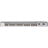


| Type of product | Router |
| Brand | HP |
| Model | StorageWorks 400 |
| Dimensions (W x D x H) | 220 x 160 x 35 mm |
| Weight | 0.6 kg |
| Power input | AC 100-240V, 50/60Hz |
| Power consumption | 15 W (max) |
| Ethernet ports | 4x Gigabit LAN, 1x Gigabit WAN |
| Wireless standard | IEEE 802.11a/b/g/n/ac |
| Frequency band | Dual-band 2.4 GHz and 5 GHz |
| Max wireless data rate | 1200 Mbps |
| Security protocols | WPA2, WPA3, WEP, firewall, VPN passthrough |
| Management interface | Web-based GUI, CLI via telnet/SSH |
| QoS support | Yes, traffic prioritization and bandwidth control |
| NAT support | Yes, static and dynamic NAT |
| Number of antennas | 4 external detachable antennas |
| LED indicators | Power, WAN, LAN, Wi-Fi, WPS |
| Operating temperature | 0°C to 40°C |
| Storage temperature | -20°C to 70°C |
| Humidity (operation) | 10% to 85% non-condensing |
| Maintenance and cleaning | Clean with a soft dry cloth; avoid liquids |
| Safety warnings | Keep away from water and heat sources; use only provided power adapter |
| Spare parts and reparability | Replacement antennas and power adapters available; user serviceable parts limited |
| Warranty | 1-year limited hardware warranty |
| Package contents | Router, power adapter, network cable, quick start guide |
Frequently Asked Questions - StorageWorks 400 HP
User questions about StorageWorks 400 HP
0 question about this device. Answer the ones you know or ask your own.
Ask a new question about this device
Download the instructions for your Router in PDF format for free! Find your manual StorageWorks 400 - HP and take your electronic device back in hand. On this page are published all the documents necessary for the use of your device. StorageWorks 400 by HP.
USER MANUAL StorageWorks 400 HP
Legal and notice information
© Copyright 2006 Hewlett-Packard Development Company, L.P.
© Copyright 2006 Brocade Communications Systems, Incorporated.
Hewlett-Packard Company makes no warranty of any kind with regard to this material, including, but not limited to, the implied warranties of merchantability and fitness for a particular purpose. Hewlett-Packard shall not be liable for errors contained herein or for incidental or consequential damages in connection with the furnishing, performance, or use of this material.
This document contains proprietary information, which is protected by copyright. No part of this document may be photocopied, reproduced, or translated into another language without the prior written consent of Hewlett-Packard. The information is provided "as is" without warranty of any kind and is subject to change without notice. The only warranties for HP products and services are set forth in the express warranty statements accompanying such products and services. Nothing herein should be construed as constituting an additional warranty. HP shall not be liable for technical or editorial errors or omissions contained herein.
Compaq Computer Corporation is a wholly-owned subsidiary of Hewlett-Packard Company.
Microsoft, Windows, Windows NT, and Windows XP are U.S. registered trademarks of Microsoft Corporation.
UNIX® is a registered trademark of The Open Group.
Printed in the US.
400 Multi-protocol Router installation guide
Contents
About this guide 7
Intended audience 7
Related documentation 7
Document conventions and symbols 8
Rack stability 9
HP technical support 9
HP-authorized reseller 9
Helpful websites 10
1 Introduction 11
Overview 11
Ports summary.... 12
Port side of the 400 MP Router 12
Port numbering in the 400 MP Router....13
Nonport side of the 400 MP Router 14
Managing the 400 MP Router 15
Supported features 16
Unsupported features 16
2 Installing and configuring the 400 MP Router 17
Installation and safety considerations 17
Items included with the 400 MP Router 18
Setting up the 400 MP Router as a standalone unit....18
Installing the 400 MP Router in an HP rack using the SAN Switch Rack Mount Kit ..... 18
Required hardware for installing in an HP rack 19
Initial setup of the 400 MP Router....28
Powering on the switch. 29
Creating a serial connection 29
Connecting to the switch using the serial connection 30
Setting the switch IP address 30
Creating an Ethernet connection 30
Setting the switch domain ID 31
Installing the SFPs and cables 31
Setting the switch date and time 32
Synchronizing the local time with an external source 33
Correcting the time zone of a switch 33
FCIP and Fibre Channel routing services configuration 34
Verifying correct operation and backing up the configuration 34
Recommendations for cable management 36
3 Operating the 400 MP Router.... 37
Interpreting LED activity 37
LEDs on the port side of the switch 37
LEDs on the nonport side of the switch 41
Interpreting POST results 42
Maintaining the 400 MP Router 43
Diagnostic tests 43
Field replaceable units (FRUs) 43
Power supplies 43
Fan Assemblies.... 44
Powering Off the 400 MP Router 44
4 Technical specifications 45
Switch components 45
Weight and physical dimensions 46
Facility requirements 46
Power supply specifications 47
Environmental requirements 47
General specifications.... 48
Data transmission ranges. 49
Memory specifications 50
Fibre Channel port specifications 50
GbE port specifications 50
Serial port specifications 51
POST and boot specifications.... 51
POST 52
Boot....52
5 Installing field-replaceable units (FRUs) 53
Power supply summary 53
Time required for power supply removal. 55
Items required for power supply removal 55
Replacing a 400 MP Router Power Supply 55
Fan assemblies summary 57
Time required for fan assembly removal 58
Items required for fan assembly removal.... 58
Replacing a 400 MP Router fan assembly 58
A Electrostatic discharge recommendations 61
Grounding methods 61
B Regulatory compliance and safety 63
Regulatory compliance 63
Federal Communications Commission notice for Class A equipment. 63
Declaration of conformity for products marked with the FCC logo, United States only ..... 63
Modifications 63
Cables 63
Regulatory compliance identification numbers 64
Laser device 64
Laser safety warning 64
Certification and classification information. 64
Laser product label 64
International notices and statements 65
Class A equipment 65
European Union notice.... 65
BSMI notice 65
Japanese notice. 66
Korean notices 66
Safety 66
Battery replacement notice 66
Taiwan battery recycling notice....67
Power cords 67
Japanese power cord notice 68
Waste Electrical and Electronic Equipment directive 68
Czechoslovakian notice 68
Danish notice 68
Waste Electrical and Electronic Equipment (WEEE) Recycling Notice 69
Estonian notice 69
Finnish notice 69
French notice 70
German notice 70
Greek notice....71
Hungarian notice....71
Italian notice....72
Latvian notice 72
Lithuanian notice 73
Polish notice 73
Portuguese notice 74
Slovakian notice 74
Slovenian notice 74
Spanish notice. 75
Swedish notice 75
Glossary 77
Index 85
Figures
1 Port side view of the 400 MP Router 12
2 Port numbering in the 400 MP Router....13
3 Nonport side of a 400 MP Router 14
4 Installing the rear mounting brackets (HP 10000 Series Rack)....21
5 Installing the rear mounting brackets (HP System/e rack—left rear upright)....22
6 Installing the outer rails (HP 10000 Series Rack) 23
7 Assembling the outer rails....24
8 Assembling the outer rails (HP System/e Rack) 25
9 Attaching the rails to the 400 MP Router. 26
10 Securing the 400 MP Router to a rack (HP 10000 Series rack) ..... 27
11 Securing the 400 MP Router to a rack (HP System/e rack) ..... 27
12 400 MP Router port side LEDs....38
13 400 MP Router Power Supplies on the nonport side 53
14 400 MP Router fan assemblies on the nonport side 57
15 Inserting the Fan Assembly in the 400 MP Router....59
16 Class 1 laser product label 64
Tables
1 Document conventions 8
2 Management options for the 400 MP Router....15
3 Rack Mount Kit rails and rail mounting hardware 19
4 tsTimeZone command parameter selection 34
5 Port side LED patterns during normal operation 39
6 Nonport side LED patterns during normal operation....41
7 Physical specifications 46
8 Power supply specifications 47
9 Environmental Requirements 47
10 General specifications 48
11 Data transmission ranges 49
12 Serial cable pinouts 51
13 Power supply status LED behavior, description, and required actions ..... 54
14 Inserting the Power Supply in the 400 MP Router....56
15 Fan status LED behavior, description, and required actions....58
About this guide
This guide provides information about:
- Setting up and configuring the HP StorageWorks 400 Multi-protocol (MP) Router
- Maintaining and operating the 400 MP Router
Intended audience
This guide is intended for system administrators and technicians who are experienced with the following:
• HP StorageWorks Fibre Channel Storage Area Network (SAN) switches
• Fabric Operating System 5.1.x or higher
Related documentation
Documentation, including white papers and best practices documents, is available on the HP website:
http://www.hp.com/support/manuals
Scroll to the storage section of the web page and select SAN infrastructure for HP StorageWorks products.
IMPORTANT: For late breaking, supplemental information, access the latest version of the HP StorageWorks Fabric OS 5.1.x release notes.
Document conventions and symbols
Table 1 Document conventions
| Convention Element | |
| Medium blue text: Figure 1 | Cross-reference links and e-mail addresses |
| Medium blue, underlined text (http://www.hp.com) | website addresses |
| Bold font | Key namesText typed into a GUI element, such as into a boxGUI elements that are clicked or selected, such as menu and list items, buttons, and check boxes |
| Italics font | Text emphasis |
| Monospace font | File and directory namesSystem outputCodeText typed at the command-line |
| Monospace, italic font | Code variablesCommand-line variables |
| Monospace, bold font | Emphasis of file and directory names, system output, code, and text typed at the command line |
⚠ WARNING! Indicates that failure to follow directions could result in bodily harm or death.
△ CAUTION: Indicates that failure to follow directions could result in damage to equipment or data.
IMPORTANT: Provides clarifying information or specific instructions.
NOTE: Provides additional information.
⚠ WARNING! To reduce the risk of personal injury or damage to equipment:
- Extend leveling jacks to the floor.
- Ensure that the full weight of the rack rests on the leveling jacks.
• Install stabilizing feet on the rack. - In multiple-rack installations, secure racks together.
- Extend only one rack component at a time. Racks may become unstable if more than one component is extended.
HP technical support
Telephone numbers for worldwide technical support are listed on the HP support website: http://www.hp.com/support/.
Collect the following information before calling:
• Technical support registration number (if applicable)
• Product serial numbers
• Product model names and numbers
• Applicable error messages
- Operating system type and revision level
• Detailed, specific questions
For continuous quality improvement, calls may be recorded or monitored.
HP strongly recommends that customers sign up online using the Subscriber's choice website: http://www.hp.com/go/e-updates.
- Subscribing to this service provides you with e-mail updates on the latest product enhancements, newest versions of drivers, and firmware documentation updates as well as instant access to numerous other product resources.
- After signing up, you can quickly locate your products by selecting Business support and then Storage under Product Category.
HP-authorized reseller
For the name of your nearest HP-authorized reseller:
• In the United States, call 1-800-282-6672.
- Elsewhere, visit the HP website: http://www.hp.com. Then click Contact HP to find locations and telephone numbers.
Helpful websites
For other product information, see the following HP websites:
- http://www.hp.com
- http://www.hp.com/go/storage
- http://www.hp.com/support/
- http://www.docs.hp.com
1 l n t r o d u c t i o n
This chapter provides the following information:
- Overview, page 11
• Port side of the 400 MP Router, page 12
• Nonport side of the 400 MP Router, page 14
• Managing the 400 MP Router, page 15
• Supported features, page 16
• Unsupported features, page 16
Overview
The 400 MP Router is a 1 Unit (U) switch with 16 Fibre Channel SFP ports and 2 physical Gigabit Ethernet (GbE) ports. It is compatible with the entire HP StorageWorks product family. It can operate independently or in a fabric containing multiple switches.
This switch is intended as a platform for Fibre Channel Routing Services and Fibre Channel over IP (FCIP). Refer to the Fabric OS Administrator's Guide for information on configuring these features.
The 400 MP Router provides the following features:
- Rack mountable 1U chassis
• 2 redundant, hot-swappable power supplies
• 3 internal temperature sensors - 3 redundant, hot-swappable fan FRUs. Each fan FRU has two fans (for a total of 6 fans). Only one fan speed is displayed per FRU using the fanShow command
- 16 Fibre Channel SFP ports supporting Fibre Channel Routing Services with link speeds up to 1-, 2-, or 4-Gbit/sec
- 2 GbE ports supporting the FCIP and Fibre Channel Routing Services features with link speeds up to 1-Gbit/sec:
• Each GbE port can support up to 8 FCIP tunnels
• Each FCIP tunnel is represented and managed as an Fibre Channel E_Port - Fibre Channel Routing Services functionality can be used over the FCIP link
- Fabrics connected through FCIP merge if the ports are configured as VE_Ports, and do not merge if they are configured as VEX_Ports. If VE_Ports are used in an Fibre Channel Routing Services backbone fabric configuration, then the backbone fabric merges but the EX_Port attached to edge fabrics do not merge. For more information see the Fabric OS Administrator's Guide.
Ports summary
The first 16 Fibre Channel ports are physical ports on the 400 MP Router, Ports 16-23 are virtual ports associated with the GE0 physical GbE link and ports 24-31 are virtual ports associated with GE1 physical GbE link. The GbE ports are displayed as ge0 and ge1 and are not assigned port numbers or area numbers.
Port side of the 400 MP Router
Figure 1 shows the port side of the 400 MP Router.

Figure 1 Port side view of the 400 MP Router
Introduction12
Port numbering in the 400 MP Router
The Fibre Channel ports are numbered from left to right, in eight-port groups, and are also numbered on the faceplate (Figure 2).

1 Fibre Channel ports 0 through 3
2 Fibre Channel ports 4 through 7
3 Fibre Channel ports 8 through 11
4 Fibre Channel ports 12 through 15
5 GbE ports (2)
Figure 2 Port numbering in the 400 MP Router
The port side of the 400 MP Router also displays the system status LED, power status LED, and port status LEDs (Figure 12 on page 38).
Nonport side of the 400 MP Router
Figure 3 shows the nonport side of the 400 MP Router, which contains the power supplies (including the AC power receptacle and AC power switch) and fans.

1 Power supply #2 2 Fan assembly #3
3 Fan assembly #2 4 Fan assembly #1
5 Power supply #1
Figure 3 Nonport side of a 400 MP Router
Managing the 400 MP Router
You can use the management functions built into the 400 MP Router to monitor the fabric topology, port status, physical status, and other information to help you analyze switch performance and to accelerate system debugging.

NOTE: The 400 MP Router automatically performs power-on self-test (POST) each time it is turned on. Any errors are recorded in the error log. For more information about POST, see "POST and boot specifications" on page 51.
For information about upgrading the version of Fabric OS installed on your switch, see the Fabric OS Administrator's Guide.
You can manage the 400 MP Router using any of the management options listed in Table 2.
Table 2 Management options for the 400 MP Router
| Management tool Out-of-band | support | In-band support |
| Command line interface (CLI)Up to two admin sessions and four user sessions simultaneously. For more information, see the Fabric OS Administrator's Guide and the Fabric OS Command Reference Manual. | Ethernet or serial management port connection | IP over Fibre Channel |
| HP Fabric ManagerFor information, see the Fabric Manager User's Guide. | Ethernet or serial management port connection | IP over Fibre Channel |
| HP Web ToolsFor information, see the Advanced Web Tools Administrator's Guide. | Ethernet or serial management port connection | IP over Fibre Channel |
| Standard SNMP applicationsFor information, see the Fabric OS MIB Reference Manual. | Ethernet or serial management port connection | IP over Fibre Channel |
| Management ServerFor information, see the Fabric OS Administrator's Guide and the Fabric OS Command Reference Manual. | Ethernet or serial management port connection | Native in-band interface (over HBA only) |
Supported features
The 400 MP Router supports the following features that are included with the firmware:
- Extended Fabrics
• Fibre Channel Routing Services - Zoning
The following optional HP software is available with the purchase of a specific license key:
• FC over IP SAN Extension (FCIP)
- Fabric Manager
- Web Tools
For information on these features, see the Fabric OS Administrator's Guide.
Unsupported features
The following HP features are not supported:
- ISL Trunking is not supported on EX_Ports on the 400 MP Router.
- Secure Fabric OS is not supported if the ports are configured as EX_Port and devices are imported from edge fabrics to backbone fabric.
2 Installing and configuring the 400 MP Router
This chapter provides the following information:
• Installation and safety considerations, page 17
• Items included with the 400 MP Router, page 18
- Setting up the 400 MP Router as a standalone unit, page 18
• Installing in an EIA cabinet, page 18
- Initial setup of the 400 MP Router, page 28
- Recommendations for cable management, page 36
Installation and safety considerations
You can install the 400 MP Router in the following ways:
- As a standalone unit on a flat surface. For instructions and more information, see "Setting up the 400 MP Router as a standalone unit" on page 18.
To install and operate the switch successfully, ensure that the following requirements are met:
- The primary AC input is 100-240 VAC (switch autosenses input voltage), 47-63 Hz.
- The primary outlet is correctly wired, protected by a circuit breaker, and grounded in accordance with local electrical codes.
- The supply circuit, line fusing, and wire size are adequate, as specified by the electrical rating on the switch nameplate.
For power supply information, see "Power supply specifications" on page 47.
To ensure adequate cooling, install the switch with the nonport side, which contains the air intake vents, facing a cool-air aisle.
Verify that the ambient air temperature does not exceed 40 × C ( 104 × F ) and that the ambient humidity remains between 20% and 85% while the switch is operating.
If installing the switch in a cabinet:
• The cabinet must be a standard EIA cabinet.
- Plan a cabinet space that is 1U (1.75 in.; 4.44 cm), 19 in. (48.3 cm) wide, and at least 24 in. (61cm) deep.
- Ground all equipment in the cabinet through a reliable branch circuit connection and maintain ground at all times. Do not rely on a secondary connection to a branch circuit, like a power strip.
- Ensure that airflow and temperature requirements are met on an ongoing basis, particularly if the switch is installed in a closed or multi-rack assembly.
- Verify that the additional weight of the switch does not exceed the cabinet's weight limits or unbalance the cabinet in any way.
- Secure the cabinet to ensure stability in case of unexpected movement.
Items included with the 400 MP Router
The following items are included with the standard shipment of the 400 MP Router:
- The 400 MP Router switch, containing three fan assemblies and two power supplies
• HP StorageWorks SAN Switch rack mount kit
• One accessory kit, containing the following items:
- Rubber mounting feet (to be used when setting up the 400 MP Router as a standalone unit)
- Two grounded 6-ft (approximately 1.83 m) power cords.
• Power plug type is NEMA5-15
• Power plug current/voltage rating: 15A/125V
- Cordage type: SVT
- Current rating/wire gauge: 10A/ 18AWG
- Connector at system end of cordset: IEC 60320/ C13
- One RJ-45 serial cable, 10-ft (approximately 3 m) long. The 400 MP Router uses an RJ-45 connector for serial port. An RJ-45 to DB9 adaptor is also provided with the switch.
Setting up the 400 MP Router as a standalone unit
The 400 MP Router can be configured as a standalone unit, which means that it resides outside of a rack.
To configure the 400 MP Router as a standalone unit:
- Unpack the 400 MP Router and verify that all ordered items are present.
- Clean the four corner depressions on the bottom of the switch and place a rubber foot in each one. This helps prevent the switch from accidentally sliding off the supporting surface.
- Place the switch on a stable, flat surface.
Installing the 400 MP Router in an HP rack using the SAN Switch Rack Mount Kit
This section provides instructions for installing the SAN Switch in an HP custom rack, as follows:
- HP System/e rack
• HP 10000 series rack
• HP 10000 G2 series rack
For optimal cable management, HP recommends that you install the HP StorageWorks SAN Switch Rack Mount Kit to allow the nonport side of the switch to slide out the cool-air side of the rack. In this installation, the port side of the switch is set 7.62 cm (3 in.) back from the edge of the rack, allowing a more gradual bend in the fiber optic cables.
Required hardware for installing in an HP rack
The following items are required to install the 400 MP Router in a rack:
- 400 MP Router
• Power cables
• #2 Phillips screwdriver
• 7/16-inch wrench or socket
The SAN Switch Rack Mount Kit rails and rail mounting hardware are listed in Table 3.
Table 3 Rack Mount Kit rails and rail mounting hardware
| Item Description | |
 | (2) rear mounting brackets |
 | A right inner rail and a right outer rail |
 | A left inner rail and a left outer rail |
 | (14) #8-32 x 3/16-inch Phillips pan-head screws with thread lock for the SAN Switch 4/32 only. |
 | (14) 8-32 x 5/16-inch Phillips pan-head SEMS screws for use with the 400 MP Router (requires ten, five on each side, to attach right and left rails) |
 | (10) #10-32 x 1/2-inch Phillips pan-head screws with captive star lock washer |
 | (8) #10 alignment washers |
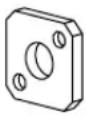 | (8) #10 adapter washers |
 | (2) 1/4-20 hex nuts with captive star lock washers |
 | (2) 1/4-inch flat washers |

CAUTION: For proper air flow, the SFP media side of the 400 MP Router must face the rear of the rack. This mounting allows air to enter from the front of the rack and to exhaust at the rear of the rack, similar to other rack-mounted equipment. This prevents overheating, which can cause failures.
To install the 400 MP Router in a rack:
- Check the contents of the shipping carton to verify that all the required parts and hardware are available.
- Choose a mounting location in the rack for the router.
- Attach the rear mounting brackets to the rear rack uprights by completing one of the following steps:
- For HP 10000 series racks (including the 10000 G2 series rack) assemble each of the two brackets with two #10-32 x 1/2-inch Phillips pan-head screws with captive star lock washers and two #10 adapter washers as shown in Figure 4.

Figure 4 Installing the rear mounting brackets (HP 10000 Series Rack)
- For an HP System/e rack, install each of the two rear mounting brackets with two #10-32 x 1/2-inch Phillips pan-head screws and two #10 alignment washers as shown in Figure 5.

Figure 5 Installing the rear mounting brackets (HP System/e rack—left rear upright)
NOTE: This kit contains both left rails and right rails. The rails are labelled Right and Left.
- Assemble the outer rails by completing the following steps:
a. Attach the left outer rail and the right outer rails to the rear mounting brackets using two 1/4-20 hex nuts with captive star lock washers. Attach the hex nuts loosely (as shown in Figure 6). Do not tighten; tighten the hex nuts later in step 7 on page 28.
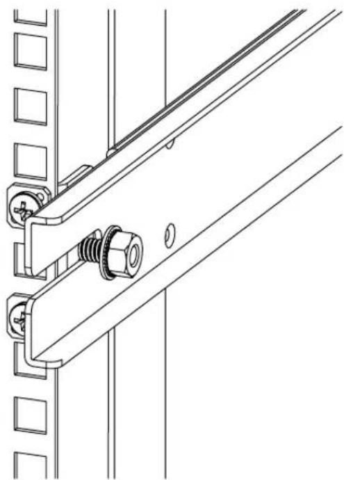
Figure 6 Installing the outer rails (HP 10000 Series Rack)
b. Depending on the rack you are using, complete one of the following tasks:
- For an HP 10000 series rack, install two #10-32 x 1/2-inch Phillips pan-head screws with captive star lock washers and two #10 adapter washers in the upper and lower hole locations of the right rail. Then install two #10-32 x 1/2-inch Phillips pan-head screws with captive star lock washers and two #10 adapter washers in the upper and lower hole locations of the left rail, as shown in Figure 7.

Figure 7 Assembling the outer rails
- For an HP System/e rack, install two #10-32 x 1/2-inch Phillips pan-head screws with captive star lock washers and two #10 alignment washers in the upper and lower hole locations of the right rail. Then install two #10-32 x 1/2-inch Phillips pan-head screws with captive star lock washers and two #10 alignment washers in the upper and lower hole locations of the left rail, as shown in Figure 8.

Figure 8 Assembling the outer rails (HP System/e Rack)

CAUTION: Do not use any screws other than the fourteen that are provided. Using longer screws can cause damage to internal components.
- For both HP 10000 series and HP System/e racks, use the mounting holes shown in Figure 9 to attach the two inner rails (one on each side) to the 400 MP Router. Use ten 8-32 x 5/16-inch Phillips pan-head SEMS screws (five on each side) of the as shown in Figure 9.
When viewing a rack from the front, the left rails are used in the left side of the rack and the right rails are used in the right side of the rack. The rails must match up—right inner with right outer and left inner with left outer. Note that the 400 MP Router mounts in the rack with its front, the port side, facing the back of the rack. The rear of the 400 MP Router, the AC side, faces the front of the rack.

NOTE: The rail kit provides fourteen #8-32 x 5/16-inch Phillips pan-head SEMS screws for assembling the inner rails onto HP StorageWorks devices. Each device requires a different number of these screws. For example, Figure 9 shows an inner rail being attached to the 400 MP Router with five screws. Attaching both inner rails requires ten screws.

25199a
Figure 9 Attaching the rails to the 400 MP Router

NOTE: This step applies to both the HP 10000 series and HP System/e racks.
- Insert the 400 MP Router into the rack and install two #10-32 x 1/2-inch Phillips pan-head screws with captive star lock washers, one on each side, as shown in Figure 10 and Figure 11.

Figure 10 Securing the 400 MP Router to a rack (HP 10000 Series rack)

Figure 11 Securing the 400 MP Router to a rack (HP System/e rack)

NOTE: To uninstall a 400 MP Router, remove the middle #10-32 x 1/2-inch Phillips pan head screw with captive star lock washer from either side of the rack uprights.
Initial setup of the 400 MP Router
The 400 MP Router must be configured correctly before it can operate within a network and fabric. For instructions on configuring the switch to operate in a fabric containing switches from other vendors, see the Fabric OS Administrator's Guide.
The following items are required for configuring and connecting the 400 MP Router for use in a network and fabric:
- The 400 MP Router, installed and connected to a power source
- A workstation computer that has a terminal emulator application (such as HyperTerminal for Windows)
- An unused IP address and corresponding subnet mask and gateway address
• The serial cable provided with the switch
• An Ethernet cable - SFP transceivers and compatible fibre cables, as required
- Access to an FTP server, for backing up (uploading) or downloading the switch configuration
To configure the 400 MP Router, you must perform the following tasks:
- Powering on the switch, page 29
- Creating a serial connection, page 29
- Connecting to the switch using the serial connection, page 30
- Setting the switch IP address, page 30
- Creating an Ethernet connection, page 30
- Setting the switch domain ID, page 31
- Installing the SFPs and cables, page 31
- Setting the switch date and time, page 32
- Synchronizing the local time with an external source, page 33
- Correcting the time zone of a switch, page 33
- FCIP and Fibre Channel routing services configuration, page 34
- Verifying correct operation and backing up the configuration, page 34

CAUTION: Do not connect the switch to the network until the IP address is correctly set.
Powering on the switch
To power on the 400 MP Router:
- Connect the power cords to both power supplies and then to power sources on separate circuits to protect against AC failure. Ensure that the cords have a minimum service loop of 6 in. available and are routed to avoid stress.
- Power on the power supplies by setting both AC switches to the 1 symbol. The power supply LEDs display amber until POST is complete, and then change to green. The switch usually requires from 1 to 3 min to boot and complete POST.

NOTE: Power is supplied to the switch as soon as the first power supply is connected and turned on.
- After POST is complete, verify that the switch power and status LEDs on the left of the port side of the switch are green.
Creating a serial connection
To create a serial connection to the 400 MP Router:
- Remove the plug from the serial port and insert the serial cable provided with the 400 MP Router.
- Connect the serial cable to the serial port on the switch and to an RS-232 serial port on the workstation. If the serial port on the workstation is RJ-45 instead of RS-232, you can remove the adapter on the end of the serial cable and insert the exposed RJ-45 connector into the RJ-45 serial port on the workstation.
- Disable any serial communication programs running on the workstation.
- Open a terminal emulator application (such as HyperTerminal for Windows or TERM in a UNIX environment) and configure the application as follows:
• In a Windows NT, 2000, 2003, ME, or XP environment:
- In a UNIX environment, enter the following command at the prompt:
tip /dev/ttyb -9600
Connecting to the switch using the serial connection
To log in to the switch through the serial connection:
- Verify that the switch has completed POST. When POST is complete, the port status and switch power and status LEDs return to a standard healthy state; for information about LED signals, see "Powering Off the 400 MP Router" on page 44.
- When the terminal emulator application stops reporting information, press Enter to display the login prompt.
- Login to the switch as admin, using the default password: password. You are prompted to change the default passwords at initial login.
Setting the switch IP address
To replace the default IP address and related information:
- Enter the ipAddrSet command at the terminal emulator application prompt, and enter the requested information at the prompts:
switch:admin> ipaddrset
Ethernet IP Address [10.77.77.77]:10.32.53.47
Ethernet Subnetmask [255.0.0.0]:255.255.240.0
Fibre Channel IP Address [0.0.0.0]: 20.32.233.48
Fibre Channel Subnetmask [0.0.0.0]: 255.255.230.0
Gateway IP Address [0.0.0.0]:10.32.48.1
IP address is being changed...Done.
Committing configuration...Done.
switch:admin>
- Optionally, verify that the address was correctly set by entering the ipAddrShow command at the prompt.
- Record the IP address on the pull out tab (Figure 1 on page 12) provided for this purpose on the port side of the 400 MP Router.
- If the serial port is no longer required, log out of the serial console, remove the serial cable, and replace the plug in the serial port.
Creating an Ethernet connection
To create an Ethernet connection to the 400 MP Router:
- Remove the plug from the Ethernet port.
- Connect an Ethernet cable to the switch Ethernet port and to the workstation or to an Ethernet network containing the workstation.

NOTE: At this point, the switch can be accessed remotely, by command line or by Web Tools. Ensure that the switch is not being modified from any other connections during the remaining tasks.
Setting the switch domain ID
To set the switch domain ID:
- Log on to the switch by telnet, using the admin account.
- Modify the domain ID if required.
The default domain ID is 1. If the switch is not powered on until after it is connected to the fabric and the default domain ID is already in use, the domain ID for the new switch is automatically reset to a unique value. If the switch is connected to the fabric after is has been powered on and the default domain ID is already in use, the fabric segments. To find the domain IDs that are currently in use, run the fabricShow command on another switch in the fabric.
a. Disable the switch by entering the switchDisable command.
b. Enter the configure command. The command prompts display sequentially; enter a new value or press Enter to accept each default value.
c. Enter y after the "Fabric param" prompt:
d. Fabric param (yes, y, no, n): [no] y
e. Enter a unique domain ID (such as the domain ID used by the previous switch, if still available):
f. Domain: (1..239) [1] 3
g. Complete the remaining prompts or press Ctrl-D to accept the remaining settings without completing all the prompts.
h. Re-enable the switch by entering the switchEnable command.
Installing the SFPs and cables
To install the SFPs and cables:
- Install the SFP transceivers in the Fibre Channel ports, as required. The ports selected for use in trunking groups must meet specific requirements. For a list of these requirements, see the Fabric OS Administrator's Guide.
a. Remove the plugs from the ports to be used.
b. Position a transceiver so that it is oriented correctly and insert it into a port until it is firmly seated and the latching mechanism clicks.
For instructions specific to the type of transceiver, see the transceiver manufacturer's documentation.

NOTE: The transceivers are keyed to ensure correct orientation. If a transceiver does not install easily, ensure that it is correctly oriented.
c. Repeat Steps a and b for the remaining ports, as required.
- Connect the cables to the transceivers.
The cables used in trunking groups must meet specific requirements. For a list of these requirements, see the Fabric OS Administrator's Guide.
△ CAUTION: A 50-micron cable should not be bent to a radius less than 2 in. under full tensile load and 1.2 in. with no tensile load. Tie wraps are not recommended for optical cables because they are easily overtightened.
a. Orient a cable connector so that the key (the ridge on one side of connector) aligns with the slot in the transceiver. Then, insert the cable into the transceiver until the latching mechanism clicks. For instructions specific to cable type, see the cable manufacturer's documentation.
NOTE: The cable connectors are keyed to ensure correct orientation. If a cable does not install easily, ensure that it is correctly oriented.
b. Repeat Step a for the remaining cables as required.
-
Check the LEDs to verify that all components are functional. For information about LED patterns, see "Powering Off the 400 MP Router" on page 44.
-
Verify the correct operation of the 400 MP Router by entering the switchShow command from the workstation.
Setting the switch date and time
The date and time switch settings are used for logging events. Switch operation does not depend on the date and time; a switch with an incorrect date and time value still functions properly.
You can synchronize the local time of the principal or primary fabric configuration server (FCS) switch to that of an external Network Time Protocol (NTP) server.
To set the date and time of a switch:
- Log in to the switch as admin.
- Enter the date command at the command line using the following syntax:
date "MMDDhhmm[CC]YY"
where:
• MM is the month (01-12)
- DD is the date (01-31)
• hh is the hour (00-23)
• mm is minutes (00-59)
- CC is the century (19-20)
- YY is the year (00-99)
Year values greater than 69 are interpreted as 1970-1999; year values less than 70 are interpreted as 2000-2069. The date function does not support Daylight Savings Time or time zones, so changes will have to be reset manually.
switch:admin> date
Fri May 5 21:50:00 UTC 1989
switch:admin>
switch:admin> date "0624165203"
Tue Jun 24 16:52:30 UTC 2003
switch:admin>
Synchronizing the local time with an external source
To synchronize the local time of the principal or primary FCS switch with that of an external NTP server:
- Log in as admin.
- Enter the tsClockServer ipaddr command.
The ipaddr variable represents the IP address of the NTP server that the switch can access. This argument is optional; by default the value is LOCL.
switch:admin> tsclockserver
LOCL
switch:admin> tsclockserver 132.163.135.131
switch:admin>
Correcting the time zone of a switch
If the time of your switch(es) is off by hours (and not minutes), use the following procedure on all switches.
To set the time zone:
- Log in as admin.
-
Enter the tsTimeZone command as follows:
tstimezone [houroffset [, minuteoffset]]
For Pacific Standard Time, enter tsTimeZone -8,0
For Central Standard Time, enter tsTimeZone -6,0
For Eastern Standard Time, enter tsTimeZone -5,0
The default time zone for switches is universal time conversion (UTC), which is 8 hours ahead of Pacific Standard Time. Additional time zone conversions are listed later in this section.
The parameters listed do not apply if the time zone of the switch(es) has already been changed from the default (8 hours ahead of PT).
For more detailed information about the command parameters, see the tsTimeZone command in the Fabric OS Command Reference Manual. -
Repeat steps 1 and 2 on all switches that the time zone needs to be set.
This needs to be done only once, because the value is stored in nonvolatile memory. For U.S. time zones, use Table 4 to determine the correct parameter for the tsTimeZone command.
Table 4 tsTimeZone command parameter selection
| Local time tsTimeZone parameter (difference from UTC) | |
| Atlantic Standard -4,0 | |
| Atlantic Daylight -3,0 | |
| Eastern Standard -5,0 | |
| Eastern Daylight -4,0 | |
| Central Standard -6,0 | |
| Central Daylight | -5,0 |
| Mountain Standard | -7,0 |
| Mountain Daylight | -6,0 |
| Pacific Standard -8,0 | |
| Pacific Daylight | -7,0 |
| Alaskan Standard | -9,0 |
| Alaskan Daylight -8,0 | |
| Hawaiian Standard | -10,0 |
FCIP and Fibre Channel routing services configuration
The ports on the 400 MP Router are initially set to persistently disabled.
If you want to enable the FC ports as a standard E_Port or F_port use the portcfgpersistentenable command to enable the ports.
If you are using the FC ports as EX_Ports you must configure the Fibre Channel Routing Services feature prior to enabling the ports.
The GbE ports can only be used once you have configured FCIP and enabled the VE_Ports.
See the Fabric OS Administrator's Guide for detailed instructions on configuring the Fibre Channel Router ports and GbE ports on the 400 MP Router.
Verifying correct operation and backing up the configuration
To verify correct operation and backup with switch configuration:
- Check the LEDs to verify that all components are functional. For information about LED patterns, see "Powering Off the 400 MP Router" on page 44.
- Run the portcfgpersistentenable command to activate the FC ports for FC operation.
- Verify the correct operation of the 400 MP Router by entering the switchShow command from the workstation.
This command provides information about switch and port status.
sw7500:admin> switchshow
switchName: sw7500
switchType: 46.2
switchState: Online
switchMode: Native
switchRole: Subordinate
switchDomain: 49
switchId: fffc31
switchWwn: 10:00:00:05:1e:37:0d:a5
zoning: ON (cfg_em)
switchBeacon: OFF
FC Router BB Fabric ID: 1
Area Port Media Speed State
0 0 id N4 Online E-Port 10:00:00:60:69:e4:20:3e "sw48000"
(upstream)(Trunk master)
1 1 id N4 No_Light
2 2 id 2G Online LS E-Port (Trunk port, master is Port 3)
3 3 id 2G Online LS E-Port 10:00:00:60:69:e4:20:3e "sw48000"
(Trunk master)
4 4 id N4 No_Light
5 5 id N4 No_Light
6 6 id N4 No_Light
7 7 id N4 No_Light
8 8 id N2 No_Light
9 9 id N2 No_Light
10 10 id N2 No_Light
11 11 id N2 No_Light
12 12 id N4 No_Light
13 13 id N4 No_Light
14 14 id N4 No_Light
15 15 id N4 No_Light
16 16 -- -- Online VE-Port 10:00:00:60:69:e4:20:3e "sw48000"
17 17 -- -- Online VE-Port 10:00:00:60:69:e4:20:3e "sw48000"
18 18 -- -- Online VE-Port 10:00:00:60:69:e4:20:3e "sw48000"
19 19 -- -- Online VE-Port 10:00:00:60:69:e4:20:3e "sw48000"
20 20 -- -- Online VE-Port 10:00:00:60:69:e4:20:3e "sw48000"
21 21 -- -- Online VE-Port 10:00:00:60:69:e4:20:3e "sw48000"
22 22 -- -- Online VE-Port 10:00:00:60:69:e4:20:3e "sw48000"
| 23 | 23 | -- | -- | Online | VE-Port | 10:00:00:60:69:e4:20:3e | "sw48000" |
| 24 | 24 | -- | -- | Online | VE-Port | 10:00:00:60:69:e4:20:3e | "sw48000" |
| 25 | 25 | -- | -- | Online | VE-Port | 10:00:00:60:69:e4:20:3e | "sw48000" |
| 26 | 26 | -- | -- | Online | VE-Port | 10:00:00:60:69:e4:20:3e | "sw48000" |
| 27 | 27 | -- | -- | Online | VE-Port | 10:00:00:60:69:e4:20:3e | "sw48000" |
| 28 | 28 | -- | -- | Online | VE-Port | 10:00:00:60:69:e4:20:3e | "sw48000" |
| 29 | 29 | -- | -- | Online | VE-Port | 10:00:00:60:69:e4:20:3e | "sw48000" |
| 30 | 30 | -- | -- | Online | VE-Port | 10:00:00:60:69:e4:20:3e | "sw48000" |
| 31 | 31 | -- | -- | Online | VE-Port | 10:00:00:60:69:e4:20:3e | "sw48000" |
| ge0 | id | 1G | Online | ||||
| ge1 | id | 1G | Online | ||||
| sw7500:admin: | |||||||
- Verify the correct operation of the 400 MP Router in the fabric by entering the fabricShow command from the workstation.
This command provides general information about the fabric.
- Back up the switch configuration to an FTP server by entering the configUpload command and following the prompts.
This command uploads the switch configuration to the server, making it available for downloading to a replacement switch if necessary.
HP recommends backing up the configuration on a regular basis to ensure that a complete configuration is available for downloading to a replacement switch. For specific instructions about how to back up the configuration, see the Fabric OS Administrator's Guide. The switchShow, fabricShow, and configUpload commands are described in detail in the Fabric OS Command Reference Manual.
Recommendations for cable management
Cables can be organized and managed in a variety of ways, such as by using cable channels or patch panels. Following is a list of recommendations:
- Plan cable management before installing the switch in a rack.
- Leave at least one meter of slack for each port cable. This provides room to remove and replace the switch, allows for inadvertent movement of the rack, and helps prevent the cables from being bent to less than the minimum bend radius.
△ CAUTION: A 50-micron cable should not be bent to a radius less than 2 in. under full tensile load and 1.2 in. with no tensile load. Tie wraps are not recommended for optical cables because they are easily overtightened.
3 Operating the 400 MP Router
This chapter provides the following information:
• Interpreting LED activity, page 37 next
• Interpreting POST results, page 42
- Maintaining the 400 MP Router, page 43
• Powering Off the 400 MP Router, page 44
Interpreting LED activity
System activity and status can be determined through the activity of the LEDs on the switch.
There are three possible LED states:
- No light
- Steady light
- Flashing light
The lights are in one of the following colors:
- Green
- Amber
The status LEDs may display amber or flash during boot, POST, or other diagnostic tests. This is normal; it does not indicate a problem unless the LEDs do not indicate a healthy state after all boot processes and diagnostic tests are complete.
LEDs on the port side of the switch
The port side of the switch has the following LEDs:
• One system status LED (above) on the left side.
• One power status LED (below) on the left side.
- Ethernet speed and status LEDs.
- One port status LED for each Fibre Channel port on the switch. The port LEDs are located in the array in the same relative positions as the ports.
• One port status LED for each GbE port.
Figure 12 shows the port side LEDs on the 400 MP Router.

1 System status LED
2 System power LED
3 Console port 4 IP address pull out tab
5 Ethernet speed LED 6 Ethernet link LED
7 Ethernet port
8 Fibre Channel ports 0-3
9 Port 0 status LED
10 GbE ports (2)
11 GEO port
Figure 12 400 MP Router port side LEDs
Table 5 describes the LEDs and their actions on the port side of the switch.
Table 5 Port side LED patterns during normal operation
| LED name LED color Status of hardware Recommended action | |||
| Power Status N | No light System is off | or there is an internal power supply failure. | Verify that system is powered on (power supply switches to “1”), the power cables attached, and your power source is live.If the system power LED is not green, the unit may be faulty.Contact HP. |
| Steady green System is on and power supplies are functioning properly. | No action required. | ||
| System Status | No light System is off or there is no power. Verify that system is on and has completed booting. | ||
| Steady green System is on and functioning properly. | No action required. | ||
| Steady amber (for more than five seconds) | Unknown state, boot failed, or the system is faulty.This LED displays steady amber during POST, this is normal and does not indicate a fault. | Perform the following steps:Connect a serial cable to the system.Reboot the system.Check the failure indicated on the system consoleContact HP. | |
| Flashing amber/green | Attention is required. A number of variables can cause this status including a single power supply failure, a fan failure, or one or more environmental ranges has exceeded. | Check the management interface and the error log for details on the cause of status.Contact HP. | |
| Ethernet Speed | No light Port speed is 10 Mb/sec. No action required. | ||
| Steady green Port speed is 100 Mb/sec. No action required. | |||
| Ethernet Link N | No light There is no link. Verify that the Ethernet cable is connected correctly. | ||
| Steady green There is a link. No action required. | |||
| Flashing green | There is link activity (traffic). | No action required. | |
| LED name LED color Status of hardware Recommended action | |||
| Port Status No | light Indicates one | of the following:No signal or light carrier (media or cable) detected.Blade may be currently initializing-connected device is configured in an offline state | Verify the power LED is on, and check the SFP and cable.Verify the blade is not currently being initialized.Verify the status of the connected device. |
| Steady green Port | is online (connected to external device) but has no traffic. | No action required. | |
| Slow-flashing green (on 1 second; then off 1 second) | Port is online but segmented because of a loopback cable or incompatible switch connection. | Verify that the correct device is attached to the blade. | |
| Fast-flashing green (on 1/4 second; then off 1/4 second) | Port is online and an internal loopback diagnostic test is running. | No action required. | |
| Flickering green Port | is online and frames are flowing through the port. | No action required. | |
| Steady amber Port | is receiving light or signal carrier, but it is not online yet. | No action required. | |
| Slow-flashing amber (on 2 seconds; then off 2 seconds) | Port is disabled because of diagnostics or the portDisable command. | Reset the port. The portCfgPersistentDisable command is persistent across reboots in Fabric OS v5.0.1. | |
| Fast-flashing amber (on 1/2 second; then off 1/2 second) | SFP or port is faulty. Replace the SFP. | Reset the port. | |
LEDs on the nonport side of the switch
The nonport side of the switch has the following LEDs:
• One power supply LED above the AC power switch on each power supply
• One fan status LED near the handle of each fan assembly
Table 6 describes the LEDs on the nonport side of the switch.
Table 6 Nonport side LED patterns during normal operation
| LED name LED color Status of hardware Recommended action | |||
| Power Supply Status | No light Power supply is not | seated correctly. | Verify that the power supply is seated correctly. |
| Steady green Power supply | is operating normally. | No action required. | |
| Steady amber (for more than five seconds) | Power supply fault for one of the following reasons:• Power supply is switched off• The power cable is disconnected• The power supply has failed• Note: When the switch is first powered on the power supply status LED will show amber until POST has completed. | Try the following:• Check the power cable connection• Verify that the power supply is powered on• Replace the power supply FRU | |
| LED name LED color | Status of hardware Recommended action | ||
| Fan Status No light | Fan assembly is not | receiving power. | No action required. |
| Steady green Fan assembly | is operating normally. | No action required. | |
| Steady amber (for more than five seconds) | Fan fault for one of the following reasons:One or more of the fan(s) in the fan assembly has failedThe fan FRU was disabled by the userNote:When the switch is first powered on the fan status LED will show amber until POST has completed. | Try the following:Verify that the fan FRU is enabled (use the fanEnable command)Replace the fan FRU | |
Interpreting POST results
POST is a system check that is performed each time the switch is powered on, rebooted, or reset, and during which the LEDs flash different colors.
To determine whether POST completed successfully and whether any errors were detected:
- Verify that the LEDs on the switch indicate that all components are healthy (LED patterns are described in Table 5 on page 39 and Table 6 on page 41). If one or more LEDs do not display a healthy state:
- Verify that the LEDs are not set to "beacon" (this can be determined through the switchShow command or Web Tools). For information about how to turn beaconing on and off, see the Fabric OS Administrator's Guide or the Advanced Web Tools Administrator's Guide.
- Follow the recommended action for the observed LED behavior, as listed in Table 5 on page 39 or Table 6 on page 41.
- Verify that diagShow command displays that the diagnostic status for all ports in the switch is OK.
- Review the system log for errors. Errors detected during POST are written to the system log, which is viewed using the errShow command. For more information about this command, see the Fabric OS Command Reference Manual. For information about specific error messages, see the Fabric OS System Error Message Reference Manual.
Maintaining the 400 MP Router
The 400 MP Router is designed for high availability and low failure; it does not require any regular physical maintenance. It includes diagnostic tests and field-replaceable units, described in the following sections.
Diagnostic tests
In addition to POST, Fabric OS includes diagnostic tests to help you troubleshoot the hardware and firmware. This includes tests of internal connections and circuitry, fixed media, and the transceivers and cables in use. The tests are implemented by command, either through a telnet session or through a terminal set up for a serial connection to the switch. Some tests require the ports to be connected by external cables, to allow diagnostics to verify the serializer/deserializer interface, transceiver, and cable. Some tests require loop back plugs.
Diagnostic tests are run at link speeds of 1-Gbit/sec, 2-Gbit/sec, and 4-Gbit/sec. For information about specific diagnostic tests, see the Fabric OS Administrator's Guide.

NOTE: Diagnostic tests might temporarily lock the transmit and receive speed of the links during diagnostic testing.
Field replaceable units (FRUs)
You can replace the power supplies and fan assemblies onsite without the use of special tools. The power supplies and fan assemblies are keyed to ensure correct orientation during installation. Replacement instructions are provided with all replacement units ordered.

WARNING! The 400 MP Router uses two power cords. To remove all power from the switch, disconnect both power cords before servicing.
Power supplies
The two power supplies are hot-swappable. They are identical and fit into either power supply slot.
Fabric OS identifies the power supplies as follows (viewing the switch from the nonport side):
• Power supply #1 on the right
• Power supply #2 on the left
Any of the following methods can be used to determine whether a power supply requires replacing:
- Check the power supply status LED next to the On/Off switch (see "LEDs on the nonport side of the switch" on page 41).
- Enter the psShow command at the command prompt to display power supply status as shown below:
  sw7500:admin> psshow
  Power Supply #1 is OK
  V10529, TQ2H0000118 ,60-0300031-01,X2, ,SP640 ,2X,TQ2H0000
  Power Supply #2 is OK
  V10529, TQ2H0000121 ,60-0300031-01,X2, ,SP640 ,2X,TQ2H0000
  sw7500:admin>
• In Web Tools, click the Power Status icon.
Fan Assemblies
The three fan assemblies are hot-swappable. They are identical and fit into any fan assembly slot.
Each fan assembly contains two fans, identified by Fabric OS as follows (viewing the switch from the nonport side):
• Fan assembly #1 on the right
• Fan assembly #2 in the center
• Fan assembly #3 on the left
Any of the following methods can be used to determine whether a fan assembly requires replacing:
- Check the fan status LED on the face of the fan assembly (see "LEDs on the nonport side of the switch" on page 41).
- Enter the fanShow command at the command prompt.
sw7500:admin> fanshow
Fan 1 is Ok, speed is 9507 RPM
Fan 2 is Ok, speed is 9246 RPM
Fan 3 is Ok, speed is 9246 RPM
sw7500:admin>
• In Web Tools, click the Fan Status icon.
Powering Off the 400 MP Router
To power off the 400 MP Router:
- Run the sysShutdown command.
- Set each AC power switch to 0.
4 Technical specifications
This chapter provides the following information:
- Switch components, page 45
• Weight and physical dimensions, page 46
• Facility requirements, page 46
• Power supply specifications, page 47
• Environmental requirements, page 47
• General specifications, page 48
• Data transmission ranges, page 49
• Memory specifications, page 50
• Fibre Channel port specifications, page 50
• GbE port specifications, page 50
• Serial port specifications, page 51
• POST and boot specifications, page 51
Switch components
The 400 MP Router switch includes the following components:
- Cabinet-mountable 1U chassis designed to be mounted in a 19-in. cabinet space, with forced-air cooling that flows from the nonport side of the switch to the port side
- Sixteen Fibre Channel ports, compatible with short wavelength (SWL), long wavelength (LWL), and extended long wavelength (ELWL) SFP transceivers
- Two GbE ports (1-Gbit/sec), compatible with short wavelength (SWL), long wavelength (LWL), and extended long wavelength (ELWL) SFP transceivers
- One IEEE-compliant RJ-45 serial cable, 10-ft (approximately 3 m) long. An RJ-45 to DB9 adaptor is also provided with the switch.
• One IEEE-compliant RJ-45 connector on the port side of the switch for use with a serial console and 10/100 MB/sec Ethernet - Switch status and management LEDs: 1 switch power LED, 1 switch status LED, 2 Ethernet LEDs, two power supply LEDs, and 3 fan LEDs
- Port status LEDs: 16 Fibre Channel port status LEDs, and 2 GbE port status LEDs
- Two universal AC input and redundant power supplies with AC switches and built-in fans
- Three fan assemblies containing two fans each. The fans have two speeds, which are set automatically and cannot be modified. They default to high speed upon boot, then switch to low speed as Fabric OS comes online, returning to high speed only as required.
Weight and physical dimensions
Table 7 lists the weight and dimensions of the 400 MP Router.
Table 7 Physical specifications
| Dimension Value | |
| Height 1U = 42.44 mm (1.67 in.) | |
| Depth 635mm (25.0 inches) | |
| Width 429 mm (16.89 in.) | |
| Weight (with two power supplies and three fan assemblies installed) | 12.43 kg (27.4 lbs) |
Facility requirements
To ensure correct operation of the switch, the facility where the switch is in use must meet the following requirements:
- Electrical:
- Primary AC input 100-240 VAC (switch autosenses input voltage), 47-63 Hz.
- Correctly wired primary outlet, protected by a circuit breaker and grounded in accordance with local electrical codes.
- Adequate supply circuit, line fusing, and wire size, as specified by the electrical rating on the switch nameplate.
- Electrical interference must be less than the levels stated in the standards listed in Table 10 on page 48, under "Immunity."
• Thermal:
- Air flows from the non-port side to the port side. A minimum air flow of 56.5 cu ft/min (96 cu m/hr) available in the immediate vicinity of the switch.
- Ambient air temperature must not exceed 40°C (104°F) while the switch is operating.
• Environmental: Specifications are listed in Table 9 on page 47.
- Cabinet:
- Cabinet space of one rack unit in a 19-in. cabinet.
- All equipment in cabinet must be grounded through a reliable branch circuit connection.
- The additional weight of the switch must not exceed the cabinet's weight limits.
- The cabinet must be secured to ensure stability in case of unexpected movement.
Power supply specifications
The power supplies are universal and capable of functioning worldwide without voltage jumpers or switches. They meet IEC 61000-4-5 surge voltage requirements and are autoranging in terms of accommodating input voltages and line frequencies. Each power supply has a built-in fan for cooling, pushing air towards the port side of the switch.
Table 8 lists the power supply specifications for the 400 MP Router.
Table 8 Power supply specifications
| Specification Value | |
| Outlet The outlet must be a correctly | wired, primary with earth ground |
| Maximum output 300 Watts | |
| System power consumption 240W | Max, 215W typical |
| Input voltage 85-264 VAC, Universal | |
| Input line frequency 47 - 63 Hz | |
| Harmonic distortion Active power factor correction | |
| BTU rating at 80% efficiency 240W | X 3.412 BTU/hr/Watts = 820 BTU/Hr |
| Inrush current Maximum of 15 amps | for period between 10-150 ms at 50 degrees C (122 degrees F), hot or cold start |
| Input line protection Fused in both hot and neutral lines, using independent fuses | |
Environmental requirements
Table 9 lists the acceptable environmental ranges for both operating and nonoperating (such as during transportation or storage) conditions.
Table 9 Environmental Requirements
| Condition | Acceptable during operation | Acceptable during non-operation |
| Ambient Temperature | 0° to 40°C(32° to 104°F) | -25° to 70°C(-13° to 158°F) |
| Humidity | 20% to 85% RH non-condensing, at 40°C (104°F), with maximum gradient of 10% per hour | 10% to 85% RH non-condensing, at 70°C (158°F) |
| Altitude | 0 to 3 km (10,000 ft) above sea level | 0 to 12 km (40,000 ft) above sea level |
| Shock | 20 G, 6 ms, half-sine wave | 15 G, 12-18 milliseconds, trapezoid |
| Vibration | 0.5 G, 5-500 Hz | 2.0 G, 5-500 Hz |
| Air Flow | 31 cu ft/min (52.7 cu m/hr) | NA |
General specifications
Table 10 lists 400 MP Router general specifications.
Table 10 General specifications
| Specification Description | |
| Configurable port types The GbE ports can be VE_Ports or VEX_Ports.The Fibre Channel ports can be E_Ports, EX_Ports, FL_Ports, or F_Ports. | |
| EMC (electromagnetic compatibility) | EmissionsAn operating 400 MP Router conforms to the emissions requirements specified by the following regulations:FCC Rules & Regulations, Part 15 subpart B, Class ACSA C108.8 Class AVCCI Class A ITECISPR 22 Class AN55022 Class AKorean EMC RequirementsBSMI Standard CNS 13438EMC Directive 89/336/EECEN50082-2/EN55024: 1998ICES-003 Class AImmunityIEC 61000-4-2 Severity Level 3 for Electrostatic DischargeIEC 61000-4-3 Severity Level 3 for Radiated FieldsIEC 61000-4-4 Severity Level 3 for Fast TransientsIEC 61000-4-5 Severity Level 3 for Surge VoltageIEC 61000-4-6 Conducted EmissionsIEC 61000-4-11 Voltage VariationsEN 61000-4-12 Oscillatory Waves ImmunityEN 61000-3-2 Limits for Harmonic Current EmissionsEN 61000-3-3 JEIDA |
| System architecture Nonblocking shared-memory switch | |
| System processor PowerPC 440GX, | 800 MHz CPU |
| ANSI Fibre Channel protocol FC-PH | (Fibre Channel Physical and Signalling Interface standard) |
| Modes of operation Fibre Channel Class 2 and Class 3 | |
| Fabric initialization Complies with FC-SW-3 Rev. 6.6 | |
| FC-IP (IP over Fibre Channel) Complies with FC-IP 2.3 of FCA profile | |
| Aggregate Switch I/O bandwidth A | total 132 Gbit/sec:• 128 Gbit/sec if all 16 FC ports are running at 4 Gbit/sec, full duplex• 4 Gbit/sec if both GbE ports are running at 1 Gbit/sec, full duplex |
| Port-to-port latency Less than 2 microseconds with no contention (destination port is free) | |
Data transmission ranges
Table 11 provides the data transmission ranges for different cable types and port speeds.
Table 11 Data transmission ranges
| Port speed Cable | size (microns) | Short wavelength (SWL) | Long wavelength (LWL) | Extended long wavelength (ELWL) |
| 1 Gbit/sec 50 500 | m (1,640 ft) NA NA | |||
| 62.5 300 m (984 ft) | NA | NA | ||
| 9 | NA | 10 km (6.2 mi) | 80 km (50 mi) | |
| 2 Gbit/sec | 50 300 m (984 ft) | NA | NA | |
| 62.5 150 m (492 ft) | NA | NA | ||
| 9 | NA | 10 km (6.2 mi) | 80 km (50 mi) | |
| 4 Gbit/sec | 50 150 m (492 ft) | NA | NA | |
| 62.5 | 70 m (230 ft) | NA | NA | |
| 9 | NA | 10 km (6.2 mi) | NA |
Up to 500km at 1G is supported when using long distance transport system such as DWDM.
Memory specifications
The 400 MP Router has three types of memory devices:
- Boot flash - 4 MB
- Compact flash - 1 G
• Main memory (SDRAM) - 512 MB
Fibre Channel port specifications
The Fibre Channel ports in the 400 MP Router are compatible with SWL, LWL, and ELWL SFP transceivers. The strength of the signal is determined by the type of transceiver in use.
The ports meet all required safety standards. For more information about these standards, see "Regulatory compliance" on page 45.
The ports are capable of operating at 1-, 2-, or 4-Gbit/sec and are able to auto-negotiate to the maximum link speed.
GbE port specifications
The GbE ports in the 400 MP Router are compatible with SWL, LWL, and ELWL SFP transceivers. The strength of the signal is determined by the type of transceiver in use.
The ports meet all required safety standards. For more information about these standards, see "Regulatory compliance" on page 45.
The GbE ports are capable of operating at 1-Gbit/sec. The 8 virtual FCIP Fibre Channel links over each physical GbE connection share this bandwidth.
Serial port specifications
The serial port is located on the port side of the switch. The 400 MP Router uses an RJ-45 connector for serial port. An RJ-45 to DB9 adaptor is also provided with the switch.

NOTE: To protect the serial port from damage, keep the cover on the port when not in use.
The serial port can be used to connect to a workstation to configure the switch IP address before connecting the switch to a fabric or IP network. The serial port's parameters are fixed at 9600 baud, 8 data bits, and no parity, with flow control set to None.
Table 12 lists the serial cable pinouts.
Table 12 Serial cable pinouts
| PIN Signal Description | |||||||
| 1 | N | o | t | s | u | p | p |
| 2 | N | o | t | s | u | p | p |
| 3 UART1_TXD Transmit data | |||||||
| 4 GND Logic ground | |||||||
| 5 GND Logic ground | |||||||
| 6 UART1_RXD Receive data | |||||||
| 7 | N | o | t | s | u | p | p |
| 8 | N | o | t | s | u | p | p |
| o | r | † | e | c |
| o | r | † | e | c |
| o | r | † | e | c |
| o | r | † | e | c |
POST and boot specifications
The 400 MP Router runs POST by default each time it is powered on; it typically requires from 1 to 3 min to boot and complete POST.
POST can be skipped after subsequent reboots by entering the fastBoot command. For more information about this command, see the Fabric OS Command Reference Manual.
POST
The success/fail results of the diagnostic tests that run during POST can be monitored through LED activity, the error log, or a command line interface.
POST includes the following tasks:
- Conduct preliminary POST diagnostics
- Initialize the operating system
- Initialize hardware
- Run diagnostic tests on several functions, including circuitry, port functionality, memory, statistics counters, and serialization
Boot
In addition to POST, boot includes the following tasks after POST is complete:
- Perform universal port configuration
- Initialize links
- Obtain a domain ID and assigning port addresses
- Construct unicast routing tables
-
Enable normal port operation
-
Analyze fabric. If any ports are connected to other switches, the switch participates in a fabric configuration
5 Installing field-replaceable units (FRUs)
This chapter provides the following information:
• Power supply summary, page 53
• Fan assemblies summary, page 57
• Replacing a 400 MP Router fan assembly, page 58
Power supply summary
The 400 MP Router integrates two power supplies, as displayed in Figure 13. Fabric OS identifies the power supplies from left to right on the nonport side as PS2 (on the left) and PS1 (on the right).
Figure 13 400 MP Router Power Supplies on the nonport side

1 Power supply #2 2 Power supply #1
CAUTION: Disassembling any part of the power supply voids the part warranty and regulatory certifications. There are no user-serviceable parts inside the power supply.
Because the cooling system relies on pressurized air, do not leave either of the power supply slots empty longer than two minutes while the switch is operating. If a power supply fails, leave it in the switch until it can be replaced.
Maintain both power supplies in operational condition to provide redundancy.
Table 13 describes the power supply status LED colors, behaviors, and actions required, if any.
Table 13 Power supply status LED behavior, description, and required actions
| LED Color and behavior | Description Action Required | |
| No light Power supply is not seated correctly. Verify that the power supply is seated correctly. | ||
| Steady green | Power supply is operating normally. No action required. | |
| Steady amber (for more than five seconds) | Power supply fault for one of the following reasons:• Power cable is disconnected• Power supply is off• Power supply has failedNote:When the switch is first powered on the power supply status will show amber until POST has completed. | Try the following:• Check the power cable connection• Verify that the power supply is powered on• Replace the power supply |
Time required for power supply removal
Replacing a power supply in the 400 MP Router should take less than two minutes.
Items required for power supply removal
You need the following items to replace a power supply in a 400 MP Router:
- 400 MP Router
- New power supply
• Phillips-head screwdriver #1
Replacing a 400 MP Router Power Supply
To replace a power supply unit in a 400 MP Router:
- To leave the switch in service while you replace a power supply, verify that the other power supply (the one not being replaced) has been powered on for at least four seconds and has a green LED.
- Power off the power supply by pressing the AC power switch to the "0" symbol. See Figure 13 for the location of the AC power switch.
- Unplug the power cord from the power supply that you are replacing.
- Unscrew the captive screw on the power supply that you are replacing using the Phillips-head screwdriver.
- Remove the power supply from the chassis by pulling the handle on the power supply out, away from the chassis.
- Install the new power supply in the chassis:

NOTE: Do not force the installation. If the power supply does not slide in easily, ensure that it is correctly oriented before continuing.
a. Orient the power supply as shown in Figure 14, with the AC power switch on the left.
b. Gently push the power supply into the chassis until it is firmly in.
c. Secure the power supply to the chassis by screwing in the captive screw using the Phillips-head screwdriver.
-
Plug the power cord in to the power supply and power on the switch by pressing the AC power switch to the "1" symbol.
-
Verify that the LED on the new power supply displays a steady green light while the switch is operating (see Table 13). If the LED is not green, ensure that the power supply is securely installed, the power plug is secure, and the primary power is available.
-
Optionally, type the psShow command at the command line prompt to display power supply status (see Figure 13 for location of Power supply #1 and Power supply #2).
Table 14 Inserting the Power Supply in the 400 MP Router

1 Power Supply 2 Captive screw
3 Handle
Fan assemblies summary
The 400 MP Router switch has three fan assemblies as displayed in Figure 14. Fabric OS identifies the fans from left to right as Fan 3, Fan 2, and Fan 1.
Figure 14 400 MP Router fan assemblies on the nonport side

CAUTION: Disassembling any part of the fan assembly voids the part warranty and regulatory certifications. There are no user-serviceable parts inside the fan assembly.
Because the cooling system relies on pressurized air, do not leave either of the fan assembly slots empty longer than two minutes while the switch is operating. If a fan assembly fails, leave it in the switch until it can be replaced.
Maintain all three fan assemblies in operational condition to provide redundancy.
Table 15 describes the fan status LED colors, behaviors, and actions required, if any.
Table 15 Fan status LED behavior, description, and required actions
| LED color and behavior | Description Action required | |
| No light Fan assembly is not receiving power. Verify that the fan FRU is seated correctly. | ||
| Steady green Fan assembly is operating normally. No action required. | ||
| Steady amber (for more than five seconds) | Fan fault for one of the following reasons:• one or more of the fan(s) in the fan assembly has failed• the fan FRU was disabled by the user | Verify that the fan FRU is enabled. If the fan FRU is enabled and the FRU is faulty it should be replaced. |
Time required for fan assembly removal
Replacing a fan assembly in the 400 MP Router switch should take less than two minutes.
Items required for fan assembly removal
You need the following items to replace a fan assembly in a400 MP Router:
• 400 MP Router switch
- New fan FRU assembly
• Phillips-head screwdriver #1
Replacing a 400 MP Router fan assembly
To replace a fan assembly in a 400 MP Router:
- Unscrew the captive screw on the fan assembly you are replacing using a Phillips-head screwdriver.
- Remove the fan assembly you are replacing from the chassis by pulling the handle out, away from the chassis.
- Install the new fan assembly in the chassis:
a. Orient the new fan assembly as shown in Figure 15 on page 59, with the captive screw on the right.
b. Gently push the fan assembly into the chassis until it is firmly in.

NOTE: Do not force the installation. If the fan assembly does not slide in easily, ensure that it is correctly oriented before continuing.
c. Secure the fan assembly to the chassis by screwing in the captive screw using the Phillips-head screwdriver.
-
Verify that the fan status LED is lit steady green to indicate normal operation (see Table 15).
-
Optionally, display the fan status using the fanShow command from the CLI (see Figure 14 for the locations of Fan assembly #1, Fan assembly #2, and Fan assembly #3).
Figure 15 Inserting the Fan Assembly in the 400 MP Router

1 Fan assembly
2 Captive screw
3 Handle
A Electrostatic discharge recommendations
To prevent damaging the system, be aware of the precautions you need to follow when setting up the system or handling parts. A discharge of static electricity from a finger or other conductor may damage system boards or other static-sensitive devices. This type of damage may reduce the life expectancy of the device.
To prevent electrostatic damage, observe the following precautions:
- Avoid hand contact by transporting and storing products in static-safe containers.
- Keep electrostatic-sensitive parts in their containers until they arrive at static-free workstations.
- Place parts on a grounded surface before removing them from their containers.
- Avoid touching pins, leads, or circuitry.
- Always make sure you are properly grounded when touching a static-sensitive component or assembly.
Grounding methods
There are several methods for grounding. Use one or more of the following methods when handling or installing electrostatic-sensitive parts:
- Use a wrist strap connected by a ground cord to a grounded workstation or computer chassis. Wrist straps are flexible straps with a minimum of 1 megohm ± 10 percent resistance in the ground cords. To provide proper ground, wear the strap snug against the skin.
- Use heel straps, toe straps, or boot straps at standing workstations. Wear the straps on both feet when standing on conductive floors or dissipating floor mats.
- Use conductive field service tools.
- Use a portable field service kit with a folding static-dissipating work mat.
If you do not have any of the suggested equipment for proper grounding, have an HP authorized reseller install the part.

NOTE: For more information on static electricity, or for assistance with product installation, contact your HP authorized reseller.
B Regulatory compliance and safety
Regulatory compliance
Federal Communications Commission notice for Class A equipment
This equipment has been tested and found to comply with the limits for a Class A digital device, pursuant to Part 15 of the FCC Rules. These limits are designed to provide reasonable protection against harmful interference when the equipment is operated in a commercial environment. This equipment generates, uses and can radiate radio frequency energy and, if not installed and used in accordance with the instruction manual, may cause harmful interference to radio communications. Operation of this equipment in a residential area is likely to cause harmful interference, in which case the user will be required to correct the interference at his own expense. The end user of this product should be aware that any changes or modifications made to this equipment without the approval of Hewlett-Packard could result in the product not meeting the Class A limits, in which case the FCC could void the user's authority to operate the equipment.
HP StorageWorks 400 MP Router Regulatory Model Number:
HSTNM-N009
Declaration of conformity for products marked with the FCC logo, United States only
This device complies with Part 15 of the FCC Rules. Operation is subject to the following two conditions: (1) this device may not cause harmful interference, and (2) this device must accept any interference received, including interference that may cause undesired operation.
For questions regarding your product, visit http://www.hp.com.
For questions regarding this FCC declaration, contact us by mail or telephone:
• Hewlett-Packard Company
P.O. Box 692000, Mailstop 510101
Houston, Texas 77269-2000
1-281-514-3333
To identify this product, refer to the part, Regulatory Model Number, or product number found on the product.
Modifications
The FCC requires the user to be notified that any changes or modifications made to this device that are not expressly approved by Hewlett-Packard Company may void the user's authority to operate the equipment.
Cables
Connections to this device must be made with shielded cables with metallic RFI/EMI connector hoods in order to maintain compliance with FCC Rules and Regulations.
Regulatory compliance identification numbers
For the purpose of regulatory compliance certifications and identification, your product has been assigned a unique Regulatory Model Number. The RMN can be found on the product nameplate label, along with all required approval markings and information. When requesting compliance information for this product, always refer to this RMN. The Regulatory Model Number should not be confused with the marketing name or model number of the product.
Laser device
All HP systems equipped with a laser device comply with safety standards, including International Electrotechnical Commission (IEC) 825. With specific regard to the laser, the equipment complies with laser product performance standards set by government agencies as a Class 1 laser product. The product does not emit hazardous light.
Laser safety warning
⚠ WARNING! To reduce the risk of exposure to hazardous radiation:
- Do not try to open the laser device enclosure. There are no user-serviceable components inside.
- Do not operate controls, make adjustments, or perform procedures to the laser device other than those specified herein.
- Allow only HP authorized service technicians to repair the laser device.
Certification and classification information
This product contains a laser internal to the fiber optic (FO) transceiver for connection to the Fibre Channel communications port.
In the USA, the FO transceiver is certified as a Class 1 laser product conforming to the requirements contained in the Department of Health and Human Services (DHHS) regulation 21 CFR, Subchapter J. A label on the plastic FO transceiver housing indicates the certification.
Outside the USA, the FO transceiver is certified as a Class 1 laser product conforming to the requirements contained in IEC 825-1:1993 and EN 60825-1:1994, including Amendment 11:1996 and Amendment 2:2001.
Laser product label
The optional label in Figure 16 or equivalent may be located on the surface of the HP supplied laser device.

Figure 16 Class 1 laser product label
This optional label indicates that the product is classified as a CLASS 1 LASER PRODUCT. This label may appear on the laser device installed in your product.
International notices and statements
This Class A digital apparatus meets all requirements of the Canadian Interference-Causing Equipment Regulations.
Products bearing the CE marking comply with the EMC Directive (89/336/EEC) and the Low Voltage Directive (73/23/EEC) issued by the Commission of the European Community and if this product has telecommunication functionality, the R&TTE Directive (1999/5/EC).
Compliance with these directives implies conformity to the following European Norms (in parentheses are the equivalent international standards and regulations):
• EN55022 (CISPR 22) - Electromagnetic Interference
EN55024 (IEC61000-4-2, IEC61000-4-3, IEC61000-4-4, IEC61000-4-5, IEC61000-4-6, IEC61000-4-8, IEC61000-4-11) - Electromagnetic Immunity
• Power Quality:
• EN61000-3-2 (IEC61000-3-2) - Power Line Harmonics
• EN61000-3-3 (IEC61000-3-3) - Power Line Flicker
• EN60950 (IEC60950) - Product Safety
- Also approved under UL 60950/CSA C22.2 No. 60950-00, Safety of Information Technology Equipment.
BSMI notice
警告使用者:
Battery replacement notice
Your switch is equipped with a lithium manganese dioxide, a vanadium pentoxide, or an alkaline internal battery or battery pack. There is a danger of explosion and risk of personal injury if the battery is incorrectly replaced or mistreated. Replacement is to be done by an HP authorized service provider using the HP spare part designated for this product. For more information about battery replacement or proper disposal, contact an HP authorized reseller or HP authorized service provider.
⚠ WARNING! Your switch contains an internal lithium manganese dioxide, a vanadium pentoxide, or an alkaline battery pack. There is risk of fire and burns if the battery pack is not properly handled. To reduce the risk of personal injury:
- Do not attempt to recharge the battery.
- Do not expose to temperatures higher than 60°C .
- Do not disassemble, crush, puncture, short external contacts, or dispose of in fire or water.
- Replace only with the HP spare part designated for this product.

Batteries, battery packs, and accumulators should not be disposed of together with the general household waste. To forward them to recycling or proper disposal, please use the public collection system or return them to HP, an authorized HP Partner, or their agents.
For more information about battery replacement or proper disposal, contact an HP authorized reseller or service provider.
Taiwan battery recycling notice

廢電池請回收
The Taiwan EPA requires dry battery manufacturing or importing firms in accordance with Article 15 of the Waste Disposal Act to indicate the recovery marks on the batteries used in sales, giveaway or promotion. Contact a qualified Taiwanese recycler for proper battery disposal.
Power cords
The power cord set must meet the requirements for use in the country where the product was purchased. If the product is to be used in another country, purchase a power cord that is approved for use in that country.
The power cord must be rated for the product and for the voltage and current marked on the product electrical ratings label. The voltage and current rating of the cord should be greater than the voltage and current rating marked on the product. In addition, the diameter of the wire must be a minimum of 1.00 mm2 or 18 AWG, and the length of the cord must be between 1.8 m (6 ft) and 3.6 m (12 ft). If you have questions about the type of power cord to use, contact an HP authorized service provider.
NOTE: Route power cords so that they will not be walked on and cannot be pinched by items placed upon or against them. Pay particular attention to the plug, electrical outlet, and the point where the cords exit from the product.
Japanese power cord notice
Waste Electrical and Electronic Equipment directive Czechoslovakian notice
Waste Electrical and Electronic Equipment (WEEE) Recycling Notice
Disposal of waste equipment by users in private household in the European Union
This symbol on the product or on its packaging indicates that this product must not be disposed of with your other household waste. Instead, it is your responsibility to dispose of your waste equipment by handing it over to a designated collection point for recycling of waste electrical and electronic equipment. The separate collection and recycling of your waste equipment at the time of disposal will help to conserve natural resources and ensure that it is recycled in a manner that protects human health and the environment. For more information about where you can drop off your waste equipment for recycling, please
contact your local city office, your household waste disposal service, or the shop where you purchased the product.
Estonian notice
This glossary defines terms used in this guide or related to this product and is not a comprehensive glossary of computer terms.
AL_PA Arbitrated loop physical address. A unique 8-bit value assigned during loop initialization to a port in an arbitrated loop.
alias server A fabric software facility that supports multicast group management.
API Application programming interface. A defined protocol that allows applications to interface with a set of services.
AW_TOV Arbitration wait time-out value. The minimum time an arbitrating L_Port waits for a response before beginning loop initialization.
backup FCS switch Backup fabric configuration server switch. The switch or switches assigned as backup in case the primary FCS switch fails.
bandwidth The total transmission capacity of a cable, link, or system. Usually measured in bps (bits per second). May also refer to the range of transmission frequencies available to a link or system.
broadcast The transmission of data from a single source to all devices in the fabric, regardless of zoning.
buffer-to-buffer flow control Management of the frame transmission rate in either a point-to-point topology or in an arbitrated loop.
CLI Command line interface. Interface that depends entirely on the use of commands, such as through telnet or SNMP, and does not involve a GUI.
compact flash Flash (temporary) memory that is used in a manner similar to hard disk storage. It is connected to a bridging component which connects to the PCI bus of the processor. Not visible within the processor's memory space.
Configuration The way in which a system is set up. May refer to hardware or software.
Hardware: The number, type, and arrangement of components that make up a system or network.
Software: The set of parameters that guide switch operation. May include general system parameters, IP address information, Domain ID, and other information. Modifiable by any login with administrative privileges.
May also refer to a set of zones.
CRC Cyclic redundancy check. A check for transmission errors that is included in every data frame.
data word A type of transmission word that occurs within frames. The frame header, data field, and CRC all consist of data words.
defined zone configuration The set of all zone objects defined in the fabric. May include multiple zone configurations.
| DLS Dynamic load sharing. Dynamic distribution of traffic over available paths. Allows for recomputing of routes when an Fx_Port or E_Port changes status. | |
| Domain ID | Unique identifier for all switches in a fabric, used in routing frames. Usually automatically assigned by the principal switch, but can be assigned manually. The Domain ID for an HP switch can be any integer between 1 and 239. Generally, the default Domain ID is 1. |
| E_D_TOV Error detect time-out value. The minimum amount of time a target waits for a sequence to complete before initiating recovery. Can also be defined as the maximum time allowed for a round-trip transmission before an error condition is declared. | |
| E_Port Expansion port. A type of switch port that can be connected to an E_Port on another switch to create an ISL. | |
| EE_Credit | End-to-end credit. The number of receive buffers allocated by a recipient port to an originating port. Used by Class 1 and 2 services to manage the exchange of frames across the fabric between source and destination. |
| enabled zone configuration | The currently enabled configuration of zones. Only one configuration can be enabled at a time. |
| end-to-end flow control | Governs flow of class 1 and 2 frames between N_Ports. |
| error As applies to Fibre Channel, a missing or corrupted frame, time-out, loss of synchronization, or loss of signal (link errors). | |
| exchange The highest level Fibre Channel mechanism used for communication between N_Ports. Composed of one or more related sequences, and can work in either one or both directions. | |
| F_Port | Fabric port. A port that is able to transmit under fabric protocol and interface over links. Can be used to connect an N_Port to a switch. |
| fabric | A Fibre Channel network containing two or more switches in addition to hosts and devices. May also be referred to as a switched fabric. |
| fabric name | The unique identifier assigned to a fabric and communicated during login and port discovery. |
| FCIA | Fibre Channel Industry Association. An international organization of Fibre Channel industry professionals. Among other things, provides oversight of ANSI and industry developed standards. |
| FCP Fibre Channel | Protocol. Mapping of protocols onto the Fibre Channel standard protocols. For example, SCSI FCP maps SCSI-3 onto Fibre Channel. |
| FCS switch | Fabric Configuration Server Switch. One or more designated HP switches that store and manage the configuration and security parameters for all switches in the fabric. FCS switches are designated by WWN, and the list of designated switches is communicated fabric-wide. |
| fill word | An IDLE or ARB ordered set that is transmitted during breaks between data frames to keep the Fibre Channel link active. |
FL_Port Fabric loop port. A port that is able to transmit under fabric protocol and also has arbitrated loop capabilities. Can be used to connect an NL_Port to a switch.
FRU Field-Replaceable Unit. A component that can be replaced on site.
FS Fibre Channel Service. A service that is defined by Fibre Channel standards and exists at a well-known address. For example, the Simple Name Server is a Fibre Channel service.
FSP Fibre Channel service protocol. The common protocol for all fabric services, transparent to the fabric type or topology.
FSPF Fabric shortest path first. HP's routing protocol for Fibre Channel switches.
Fx_Port A fabric port that can operate as either an F_Port or FL_Port.
G_Port Generic port. A port that can operate as either an E_Port or F_Port. A port is defined as a G_Port when it is not yet connected or has not yet assumed a specific function in the fabric.
hard address The AL_PA that an NL_Port attempts to acquire during loop initialization.
idle Continuous transmission of an ordered set over a Fibre Channel link when no data is being transmitted, to keep the link active and maintain bit, byte, and word synchronization.
integrated fabric The fabric created by connecting multiple HP switches with multiple ISL cables, and configuring the switches to handle traffic as a seamless group.
ISL trunking The distribution of traffic over the combined bandwidth of multiple ISLs. A set of trunked ISLs is called a trunking group, and the ports in a trunking group are called trunking ports.
isolated E_Port An E_Port that is online but not operational due to overlapping Domain IDs or nonidentical parameters (such as E_D_TOVs).
K28.5 A special 10-bit character used to indicate the beginning of a transmission word that performs Fibre Channel control and signaling functions. The first seven bits of the character are the comma pattern.
kernel flash Flash (temporary) memory connected to the peripheral bus of the processor, and visible within the processor's memory space. Also known as user flash.
L_Port Loop port. A node port (NL_Port) or fabric port (FL_Port) that has arbitrated loop capabilities. An L_Port can be in one of two modes:
Fabric mode: F Connected to a port that is not loop capable, and using fabric protocol.
Loop mode: In an arbitrated loop and using loop protocol. An L_Port in loop mode can also be in participating mode or non-participating mode.
latency The period of time required to transmit a frame, from the time it is sent until it arrives. Together, latency and bandwidth define the speed and capacity of a link or system.
link As applies to Fibre Channel, a physical connection between two ports, consisting of both transmit and receive fibres.
link services A protocol for link-related actions.
| LIP Loop initialization primitive. The signal used to begin initialization in a loop.Indicates either loop failure or resetting of a node. | |
| LM_TOV | Loop master time-out value. The minimum time that the loop master waits for a loop initialization sequence to return. |
| loop failure | Loss of signal within a loop for any period of time, or loss of synchronization for longer than the time-out value. |
| loop initialization | The logical procedure used by an L_Port to discover its environment. Can be used to assign AL_PA addresses, detect loop failure, or reset a node. |
| Loop_ID A hex value representing one of the 127 possible AL_PA values in an arbitrated loop. | |
| LPSM | Loop Port State Machine. The logical entity that performs arbitrated loop protocols and defines the behavior of L_Ports when they require access to an arbitrated loop. |
| LWL Long wavelength. A type of fiber optic cabling that is based on 1300mm lasers and supports link speeds up to 2 Gbit/sec. May also refer to the type of transceiver. | |
| master port | The port that determines the routing paths for all traffic flowing through a trunking group. One of the ports that is in the first ISL in the trunking group is designated as the master port for that group. |
| MIB Management Information Base. An SNMP structure to help with device management, providing configuration and device information. | |
| multicast | The transmission of data from a single source to multiple specified N_Ports (as opposed to all the ports on the network). |
| N_Port | Node port. A port on a node that can connect to a Fibre Channel port or to another N_Port in a point-to-point connection. |
| name server Frequently used to indicate Simple Name Server. | |
| NL_Port | Node loop port. A node port that has arbitrated loop capabilities. Used to connect an equipment port to the fabric in a loop configuration through an FL_Port. |
| node A Fibre Channel device that contains an N_Port or NL_Port. | |
| non-participating mode | A mode in which an L_Port in a loop is inactive and cannot arbitrate or send frames, but can retransmit any received transmissions. This mode is entered if there are more than 127 devices in a loop and an AL_PA cannot be acquired. |
| Nx_Port | A node port that can operate as either an N_Port or NL_Port. |
| packet | A set of information transmitted across a network. |
| participating mode | A mode in which an L_Port in a loop has a valid AL_PA and can arbitrate, send frames, and retransmit received transmissions. |
| path selection | The selection of a transmission path through the fabric. HP switches use the FSPF protocol. |
| phantom address | An AL_PA value that is assigned to an device that is not physically in the loop. Also known as phantom AL_PA. |
| phantom device | A device that is not physically in an arbitrated loop but is logically included through the use of a phantom address. |
| PLOGI | Port login. The port-to-port login process by which initiators establish sessions with targets. |
| point-to-point A Fibre Channel topology that employs direct links between each pair of communicating entities. | |
| port cage The metal casing extending out of the Fibre Channel port on the switch, and into which a GBIC or SFP transceiver can be inserted. | |
| Port_Name | The unique identifier assigned to a Fibre Channel port. Communicated during login and port discovery. |
| POST Power On Self-Test. A series of tests run by a switch after it is powered on. | |
| primary FCS switch | Primary fabric configuration server switch. The switch that actively manages the configuration and security parameters for all switches in the fabric. |
| private loop An arbitrated loop that does not include a participating FL_Port. | |
| private NL_Port | An NL_Port that communicates only with other private NL_Ports in the same loop and does not log into the fabric. |
| public device | A device that supports arbitrated loop protocol, can interpret 8-bit addresses, and can log into the fabric. |
| public loop | An arbitrated loop that includes a participating FL_Port, and may contain both public and private NL_Ports. |
| public NL_Port | An NL_Port that logs into the fabric, can function within either a public or a private loop, and can communicate with either private or public NL_Ports. |
| quad A group of four adjacent ports that share a common pool of frame buffers. | |
| R_A_TOV | Resource allocation time-out value. The maximum time a frame can be delayed in the fabric and still be delivered. |
| RAID | Redundant Array Of Independent Disks. A collection of disk drives that appear as a single volume to the server and are fault tolerant through mirroring or parity checking. |
| request rate The rate at which requests arrive at a servicing entity. | |
| route | As applies to a fabric, the communication path between two switches. May also apply to the specific path taken by an individual frame, from source to destination. |
| routing | The assignment of frames to specific switch ports, according to frame destination. |
| RR_TOV | Resource recovery time-out value. The minimum time a target device in a loop waits after a LIP before logging out a SCSI initiator. |
| RSCN | Registered state change notification. A switch function that allows notification of fabric changes to be sent from the switch to specified nodes. |
| SAN | Storage Area Network. A network of systems and storage devices that communicate using Fibre Channel protocols. |
| SDRAM | The main memory for the switch. |
| sequence | A group of related frames transmitted in the same direction between two N_Ports. |
| service rate | The rate at which an entity can service requests. |
| single mode | The fiber optic cabling standard that corresponds to distances of up to 10 km between devices. |
| SNMP | Simple Network Management Protocol. An internet management protocol that uses either IP for network-level functions and UDP for transport-level functions, or TCP/IP for both. Can be made available over other protocols, such as UDP/IP, because it does not rely on the underlying communication protocols. |
| SNS Simple Name | Server. A switch service that stores names, addresses, and attributes for up to 15 minutes, and provides them as required to other devices in the fabric. SNS is defined by Fibre Channel standards and exists at a well-known address. May also be referred to as directory service. |
| switch | Hardware that routes frames according to Fibre Channel protocol and is controlled by software. |
| switch port | A port on a switch. Switch ports can be E_Ports, F_Ports, or FL_Ports. |
| SWL Short wavelength. | A type of fiber optic cabling that is based on 850mm lasers and supports link speeds up to 2 Gbit/sec. May also refer to the type of transceiver. |
| tenancy | The time from when a port wins arbitration in a loop until the same port returns to the monitoring state. Also referred to as loop tenancy. |
| throughput | The rate of data flow achieved within a cable, link, or system. Usually measured in bps (bits per second). |
| topology | As applies to Fibre Channel, the configuration of the Fibre Channel network and the resulting communication paths allowed. There are three possible topologies: Point-to-point: A direct link between two communication ports. Switched fabric: Multiple N_Ports linked to a switch by F_Ports. Arbitrated loop: Multiple NL_Ports connected in a loop |
| transmission character | A 10-bit character encoded according to the rules of the 8b/10b algorithm. |
| transmission word | A group of four transmission characters. |
| trap (SNMP) | The message sent by an SNMP agent to inform the SNMP management station of a critical error. |
| U_Port | Universal port. A switch port that can operate as a G_Port, E_Port, F_Port, or FL_Port. A port is defined as a U_Port when it is not connected or has not yet assumed a specific function in the fabric. |
| well-known address | As pertaining to Fibre Channel, a logical address defined by the Fibre Channel standards as assigned to a specific function, and stored on the switch. |
| workstation | A computer used to access and manage the fabric. May also be referred to as a management station or host. |
| WWN | World Wide Name. An identifier that is unique worldwide. Each entity in a fabric has a separate WWN. |
zone A set of devices and hosts attached to the same fabric and configured as being in the same zone. Devices and hosts within the same zone have access permission to others in the zone, but are not visible to any outside the zone.
zone configuration A specified set of zones. Enabling a configuration enables all zones in that configuration.
Index
A
accumulators 67
alkaline battery warning 67
audience 7
authorized reseller, HP 9
Avis Canadien, regulatory compliance notice 65
B
batteries
recycling or disposal 67
replacement
notice 66
warning 67
Taiwan EPA recycling and disposal 67
boot 52
BSMI, regulatory compliance notice 65
C
cables
FCC compliance statement 63
shielded 63
Canada, regulatory compliance notice 65
certification and classification information, laser 64
Class A equipment, Canadian compliance statement 65
connect to the switch using the serial connection 30
conventions
document 8
text symbols 8
correct the time zone of a switch 33
create a serial connection 29
create an ethernet connection 30
D
data transmission ranges 49
date setting 32
declaration of conformity 63
diagnostic tests 43
directive, waste electrical and electronic equipment 68
disposal
waste equipment for EU private households 69
disposal, battery 67
disposal, Taiwan EPA battery 67
document
conventions 8
related documentation 7
domain ID 31
E
environmental requirements 47
European Union, regulatory compliance notice 65
F
facility requirements 46
FCC (Federal Communications Commission) declaration of conformity 63 modifications 63
FCIP and Fibre Channel Routing Services configuration 34
features not supported 16
Fibre Channel port specifications 50
field replaceable units (FRUs) 43
G
GbE port specifications 50
general specifications 48
German noise declaration 66
H
hardware
rails and rail mounting 19
help, obtaining 9, 10
HP
address for
FCC questions 63
authorized reseller 9
series number 64
storage web site 10
Subscriber's choice web site 9
technical support 9
telephone number
FCC questions 63
|
IEC EMC, worldwide regulatory compliance notice 65
initial setup of the 400 MP Router 28
install SFPs and cable the switch 31
installation and safety considerations 17
interpreting led activity 37
interpreting post results 42
IP address 30
items included with the 400 MP Router 18
J
Japan
regulatory compliance notice 66
K
Korean, regulatory compliance notice 66
L
label, laser 64
laser
international certification and classification
information 64
product label 64
radiation, warning 64
regulatory compliance notice 64
LEDs on the nonport side of the switch 41
LEDs on the port side of the switch 37
lithium battery 66
M
maintaining the 400 MP Router 43
managing the 400 MP Router 15
memory specifications 50
N
noise declaration, German 66
nonport side view 14
O
overview of 400 MP Router 11
P
port side view 12
post 52
post and boot specifications 51
power cord
compliance notice 67
replacement 67
set 67
power supply specifications 47
powering off 44
provide power to the switch 29
R
rack stability, warning 9
rails 19
recommendations for cable management 36
recycling, battery 67
recycling, Taiwan EPA battery 67
regulatory compliance
information number 64
notices
BSMI 65
Canada 65
European Union 65
HP series number 64
IEC EMC statement, worldwide 65
Japan 66
Korean 66
lasers 64
modifications 63
shielded cables 63
related documentation 7
replacing a power cord 67
RFI/EMI connector hoods 63
S
serial port specifications 51
series number, regulatory compliance 64
set the switch date and time 32
set the switch domain ID 31
set the switch IP address 30
setting up as a standalone unit 18
Subscriber's choice, HP 9
supported features 16
switch components 45
symbols in text 8
synchronize local time with an external source 33
T
Taiwan EPA battery recycling and disposal 67
technical support, HP 9
telephone numbers
FCC questions 63
text symbols 8
time setting 32
V
verify correct operation and backup the
configuration 34
W
warning
rack stability 9
warnings
alkaline batteries 67
battery replacement 67
lasers, radiation 64
waste electrical and electronic equipment directive 68
waste equipment disposal for EU private households 69
web sites
HP storage 10
HP Subscriber's choice 9
weight and physical dimensions 46


- LEGAL AND NOTICE INFORMATION
- CONTENTS
- ABOUT THIS GUIDE
- INTRODUCTION
- INSTALLING AND CONFIGURING THE 400 MP ROUTER
- OPERATING THE 400 MP ROUTER
- TECHNICAL SPECIFICATIONS
- INSTALLING FIELD-REPLACEABLE UNITS (FRUS)
- A ELECTROSTATIC DISCHARGE RECOMMENDATIONS
- B REGULATORY COMPLIANCE AND SAFETY
- FIGURES
- TABLES
- INTENDED AUDIENCE
- RELATED DOCUMENTATION
- DOCUMENT CONVENTIONS AND SYMBOLS
- HP TECHNICAL SUPPORT
- HP-AUTHORIZED RESELLER
- HELPFUL WEBSITES
- L N T R O D U C T I O N
- OVERVIEW
- PORTS SUMMARY
- PORT SIDE OF THE 400 MP ROUTER
- PORT NUMBERING IN THE 400 MP ROUTER
- NONPORT SIDE OF THE 400 MP ROUTER
- MANAGING THE 400 MP ROUTER
- SUPPORTED FEATURES
- UNSUPPORTED FEATURES
- INSTALLATION AND SAFETY CONSIDERATIONS
- ITEMS INCLUDED WITH THE 400 MP ROUTER
- SETTING UP THE 400 MP ROUTER AS A STANDALONE UNIT
- INSTALLING THE 400 MP ROUTER IN AN HP RACK USING THE SAN SWITCH RACK MOUNT KIT
- REQUIRED HARDWARE FOR INSTALLING IN AN HP RACK
- INITIAL SETUP OF THE 400 MP ROUTER
- POWERING ON THE SWITCH
- CREATING A SERIAL CONNECTION
- CONNECTING TO THE SWITCH USING THE SERIAL CONNECTION
- SETTING THE SWITCH IP ADDRESS
- CREATING AN ETHERNET CONNECTION
- SETTING THE SWITCH DOMAIN ID
- INSTALLING THE SFPS AND CABLES
- SETTING THE SWITCH DATE AND TIME
- SYNCHRONIZING THE LOCAL TIME WITH AN EXTERNAL SOURCE
- CORRECTING THE TIME ZONE OF A SWITCH
- FCIP AND FIBRE CHANNEL ROUTING SERVICES CONFIGURATION
- VERIFYING CORRECT OPERATION AND BACKING UP THE CONFIGURATION
- RECOMMENDATIONS FOR CABLE MANAGEMENT
- INTERPRETING LED ACTIVITY
- LEDS ON THE PORT SIDE OF THE SWITCH
- LEDS ON THE NONPORT SIDE OF THE SWITCH
- INTERPRETING POST RESULTS
- MAINTAINING THE 400 MP ROUTER
- DIAGNOSTIC TESTS
- FIELD REPLACEABLE UNITS (FRUS)
- POWER SUPPLIES
- FAN ASSEMBLIES
- POWERING OFF THE 400 MP ROUTER
- SWITCH COMPONENTS
- WEIGHT AND PHYSICAL DIMENSIONS
- FACILITY REQUIREMENTS
- POWER SUPPLY SPECIFICATIONS
- ENVIRONMENTAL REQUIREMENTS
- GENERAL SPECIFICATIONS
- DATA TRANSMISSION RANGES
- MEMORY SPECIFICATIONS
- FIBRE CHANNEL PORT SPECIFICATIONS
- GBE PORT SPECIFICATIONS
- SERIAL PORT SPECIFICATIONS
- POST AND BOOT SPECIFICATIONS
- POST
- BOOT
- POWER SUPPLY SUMMARY
- TIME REQUIRED FOR POWER SUPPLY REMOVAL
- ITEMS REQUIRED FOR POWER SUPPLY REMOVAL
- REPLACING A 400 MP ROUTER POWER SUPPLY
- FAN ASSEMBLIES SUMMARY
- TIME REQUIRED FOR FAN ASSEMBLY REMOVAL
- ITEMS REQUIRED FOR FAN ASSEMBLY REMOVAL
- REPLACING A 400 MP ROUTER FAN ASSEMBLY
- GROUNDING METHODS
- REGULATORY COMPLIANCE
- FEDERAL COMMUNICATIONS COMMISSION NOTICE FOR CLASS A EQUIPMENT
- DECLARATION OF CONFORMITY FOR PRODUCTS MARKED WITH THE FCC LOGO, UNITED STATES ONLY
- MODIFICATIONS
- CABLES
- REGULATORY COMPLIANCE IDENTIFICATION NUMBERS
- LASER DEVICE
- LASER SAFETY WARNING
- CERTIFICATION AND CLASSIFICATION INFORMATION
- LASER PRODUCT LABEL
- INTERNATIONAL NOTICES AND STATEMENTS
- BSMI NOTICE
- BATTERY REPLACEMENT NOTICE
- TAIWAN BATTERY RECYCLING NOTICE
- 廢電池請回收
- POWER CORDS
- JAPANESE POWER CORD NOTICE
- WASTE ELECTRICAL AND ELECTRONIC EQUIPMENT DIRECTIVE CZECHOSLOVAKIAN NOTICE
- WASTE ELECTRICAL AND ELECTRONIC EQUIPMENT (WEEE) RECYCLING NOTICE
- DISPOSAL OF WASTE EQUIPMENT BY USERS IN PRIVATE HOUSEHOLD IN THE EUROPEAN UNION
- ESTONIAN NOTICE
- INDEX
- A
- B
- C
- D
- E
- F
- G
- H
- J
- K
- L
- M
- N
- O
- P
- R
- S
- T
- V
- W
Brand : HP
Model : StorageWorks 400
Category : Router