
FlexNetwork MSR954 - Router HP - Free user manual and instructions
Find the device manual for free FlexNetwork MSR954 HP in PDF.


| Product Type | Router |
| Brand | HP |
| Model | FlexNetwork MSR954 |
| Dimensions (W x D x H) | 252 x 177 x 44 mm |
| Weight | 1.4 kg |
| Power Supply | AC 100-240V, 50-60 Hz |
| Power Consumption | 12 W (typical) |
| Network Interfaces | 4 x Gigabit Ethernet LAN, 1 x Gigabit Ethernet WAN |
| USB Ports | 1 x USB 2.0 |
| LED Indicators | Power, Status, LAN/WAN activity |
| Routing Protocols | Static, RIP, OSPF, BGP |
| Security Features | Stateful firewall, NAT, VPN (IPsec, SSL) |
| VLAN Support | IEEE 802.1Q |
| Quality of Service | Traffic shaping, priority queuing |
| Management | Web GUI, CLI, SNMP |
| Operating Temperature | 0 °C to 40 °C |
| Storage Temperature | -40 °C to 70 °C |
| Humidity | 10% to 90% non-condensing |
| Certifications | CE, FCC, RoHS |
| Warranty | Limited lifetime warranty (terms apply) |
| Repairability | No user-serviceable parts; contact support |
Frequently Asked Questions - FlexNetwork MSR954 HP
User questions about FlexNetwork MSR954 HP
0 question about this device. Answer the ones you know or ask your own.
Ask a new question about this device
Download the instructions for your Router in PDF format for free! Find your manual FlexNetwork MSR954 - HP and take your electronic device back in hand. On this page are published all the documents necessary for the use of your device. FlexNetwork MSR954 by HP.
USER MANUAL FlexNetwork MSR954 HP
HPE FlexNetwork MSR 954 Routers Installation Guide
© Copyright 2016 Hewlett Packard Enterprise Development LP
The information contained herein is subject to change without notice. The only warranties for Hewlett Packard Enterprise products and services are set forth in the express warranty statements accompanying such products and services. Nothing herein should be construed as constituting an additional warranty. Hewlett Packard Enterprise shall not be liable for technical or editorial errors or omissions contained herein.
Confidential computer software. Valid license from Hewlett Packard Enterprise required for possession, use, or copying. Consistent with FAR 12.211 and 12.212, Commercial Computer Software, Computer Software Documentation, and Technical Data for Commercial Items are licensed to the U.S. Government under vendor's standard commercial license.
Links to third-party websites take you outside the Hewlett Packard Enterprise website. Hewlett Packard Enterprise has no control over and is not responsible for information outside the Hewlett Packard Enterprise website.
Acknowledgments
Intel®, Itanium®, Pentium®, Intel Inside®, and the Intel Inside logo are trademarks of Intel Corporation in the United States and other countries.
Microsoft® and Windows® are trademarks of the Microsoft group of companies.
Adobe® and Acrobat® are trademarks of Adobe Systems Incorporated.
Java and Oracle are registered trademarks of Oracle and/or its affiliates.
UNIX® is a registered trademark of The Open Group.
Contents
Preparing for installation 1
Safety recommendations ....1
Safety symbols....1
General safety recommendations
Electricity safety
ESD prevention
Examining the installation site
Temperature and humidity
Cleanliness
Cooling
EMI
Lightning protection
Installation accessories and tools
Pre-installation checklist
Installing the router
Installation prerequisites
Installation flowchart
Installing the router
Mounting the router on a workbench 8
Mounting the router on a wall 9
Installing the router in a rack 10
Grounding the router 12
Installing a 4G SIM card (JH296A/JH297A/JH298A/JH299A)....14
Installing a 4G SIM card (JH373A) 14
Installing a Micro SD card 17
Installing a 4G antenna 18
Connecting a 4G antenna extension cable to a 4G router....19
Installing a WLAN antenna 19
Connecting Ethernet interface cables 20
Connecting the console cable and setting terminal parameters 20
Connecting the power cord 21
Verifying the installation 22
Accessing the router for the first time 22
Powering on the router
Observing the startup process
Power-on check
Configuring basic settings for the router
Troubleshooting
Power supply failure
Symptom
Solution
No display on the configuration terminal
Symptom
Solution
Garbled display on the configuration terminal
No response from the serial port
Symptom
Solution
3G/4G SIM card and 4G antenna failures 26
Symptom 26
Solution 26
Restoring the factory settings 27
Scenario 1 27
Scenario 2 27
Scenario 3 27
Reset button usage guidelines 27
Appendix A Chassis views and technical specifications 29
Chassis views 29
JH296A 29
JH297A 30
JH298A 30
JH299A 31
JH373A 32
Technical specifications 32
Appendix B LEDs 34
LEDs 34
JH296A 34
JH297A 34
JH298A 35
JH299A 35
JH373A 36
LED description 36
Document conventions and icons 39
Conventions 39
Network topology icons 40
Support and other resources 41
Accessing Hewlett Packard Enterprise Support 41
Accessing updates 41
Websites 42
Customer self repair 42
Remote support 42
Documentation feedback 43
Index 44
Preparing for installation
The HPE MSR954 Router Series includes the models in Table 1.
Table 1 HPE MSR954 Router Series models
| Product code HPE description RMN | |
| JH296A HPE MSR95X 1GbE+SFP Router BJNGA-BB0036 | |
| JH297A HPE MSR95X-W 1GbE+SFP (WW) Router BJNGA-BB0037 | |
| JH298A HPE MSR95X-W 1GbE+SFP LTE (AM) Router BJNGA-BB0038 | |
| JH299A HPE MSR95X-W 1GbE+SFP LTE (WW) Router BJNGA-BB0039 | |
| JH373A HPE MSR954 1GbE Dual 4G (WW) Router BJNGA-BB0042 |
IMPORTANT:
For regulatory identification purposes, every MSR954 router is assigned a regulatory model number (RMN). These regulatory model numbers should not be confused with the marketing name HPE MSR954 or the product codes.
Safety recommendations
To avoid any equipment damage or bodily injury, read the following safety recommendations before installation. Note that the recommendations do not cover every possible hazardous condition.
Safety symbols
When reading this document, note the following symbols:
WARNING means an alert that calls attention to important information that if not understood or followed can result in personal injury.
△ CAUTION means an alert that calls attention to important information that if not understood or followed can result in data loss, data corruption, or damage to hardware or software.
General safety recommendations
- Keep the router and installation tools away from walk areas.
- Place the router in a dry and flat location and make sure anti-slip measures are in place.
- Remove all external interface cables and power cords before moving the router.
Electricity safety
- Locate the external power switch in the room before installation. Shut off the power immediately if an accident occurs.
- Make sure the router is reliably grounded.
- Do not remove and install the chassis cover when the router is operating.
- Connect the interface cables correctly.
- Use an uninterrupted power supply (UPS).
- Do not work alone when the router has power • Always make sure the power has been disconnected during installation or replacement.
ESD prevention
WARNING!
Check the resistance of the ESD wrist strap for safety. The resistance reading should be in the range of 1 to 10 megohm (Mohm) between a human body and the ground.
To prevent electrostatic discharge (ESD), follow these guidelines:
• Make sure the router and the floor are reliably grounded. - Keep the equipment room clean to reduce the negative effects of dusts and particles. - Maintain the humidity and temperature levels in the acceptable range. - Always wear an ESD wrist strap. Make sure the wrist strap makes good skin contact and is reliably grounded.
No ESD wrist strap is provided with the router. Prepare it yourself.
To attach an ESD wrist strap:
- Wear the wrist strap on your wrist.
- Lock the wrist strap tight around your wrist to maintain good contact with the skin.
- Secure the wrist strap lock and the alligator clip lock together.
- Attach the alligator clip to the grounding screw on the router.
Examining the installation site
The router can only be used indoors. To ensure correct operation and a long lifespan for your router, the installation site must meet the requirements in this section.
Temperature and humidity
Maintain the temperature and humidity in the equipment room as described in Table 2.
- Lasting high relative humidity can cause poor insulation, electricity creepage, mechanical property change of materials, and metal corrosion.
- Lasting low relative humidity can cause washer contraction and ESD and bring problems including loose captive screws and circuit failure.
- High temperature can accelerate the aging of insulation materials and significantly lower the reliability and lifespan of the router.
Table 2 Temperature/humidity requirements in the equipment room
| Temperature | Relative | humidity |
| 0°C to 45°C (32°F to 113°F) 5% to 95%, noncondensing |
Cleanliness
Dust buildup on the chassis might result in electrostatic adsorption, which causes poor contact of metal components and contact points, especially when indoor relative humidity is low. In the worst case, electrostatic adsorption can cause communication failure.
Table 3 Dust concentration limit in the equipment room
| Substance Concentration limit (particles/m3) | |
| Dust particles | ≤ 3 × 10⁴ (No visible dust on the tabletop in three days) |
| NOTE:Dust diameter ≥ 5 μm | |
The equipment room must also meet strict limits on salts, acids, and sulfides to eliminate corrosion and premature aging of components, as shown in Table 4.
Table 4 Harmful gas limits in an equipment room
| Gas Maximum concentration (mg/m) | 3 |
| SO2 | 0.2 |
| H2S | 0.006 |
| NH3 | 0.05 |
| Cl2 | 0.01 |
Cooling
- Maintain a minimum clearance of 10 cm (3.94 in) around the air vents. Make sure the installation site has a good ventilation system.
EMI
All electromagnetic interference (EMI) sources, from outside or inside of the router and application system, adversely affect the router in the following ways:
- A conduction pattern of capacitance coupling.
- Inductance coupling. Electromagnetic wave radiation. Common impedance (including the grounding system) coupling.
To prevent EMI, perform the following tasks:
- If AC power is used, use a single-phase three-wire power receptacle with protection earth (PE) to filter interference from the power grid.
- Keep the router far away from radio transmitting stations, radar stations, and high-frequency devices. Use electromagnetic shielding, for example, shielded interface cables, when necessary.
Lightning protection
To protect the router from lightning, follow these guidelines:
Make sure the router is reliably grounded by using a grounding cable. Make sure the AC power receptacle is reliably grounded. Install a lightning protector at each power input end.
Installation accessories and tools
Table 5 Installation accessories
| Product code | Description | Quantity Applicable models | |
| JG669A | 4G antenna | 2 | JH298AJH299A |
| JG669A | 4G antenna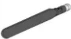 | 4 | JH373A |
| 5189-9346 | WLAN antenna | 2 | JH297AJH298AJH299A |
| 5188-9371 | Grounding cable | 1 | JH296AJH297AJH298AJH299AJH373A |
| N/A | Floating nut[6GS4] | User supplied | JH296AJH297AJH298AJH299AJH373A |
| N/A | M6 screw | User supplied | JH296AJH297AJH298AJH299AJH373A |
| N/A | M4 screw | User supplied | JH296AJH297AJH298AJH299AJH373A |
| JH316A | Mounting brackets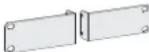 | User supplied | JH296AJH297AJH298AJH299A |
| N/A | Wall anchor and screw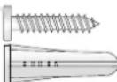 | User supplied | JH296AJH297AJH298AJH299A |
| Product code | Description | Quantity | Applicable models | |
| 5184-7298 | Rubber feet | 1 kit | JH296AJH297AJH298AJH299AJH373A | |
| 5190-1728 | Bail latch | 1 kit | JH296AJH297AJH298AJH299A | |
| 5190-1727 | Console cable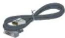 | 1 kit | JH296AJH297AJH298AJH299AJH373A | |
Figure 1 User-supplied tools and equipment
Ruler
Wire-stripping pliers
Rubber hammer
ESD wrist strap
Flathead screwdriver

Drill, marker, diagonal pliers

Phillips screwdriver
Pre-installation checklist
| Item | Requirements | |
| Installation site | Ventilation | There is a minimum clearance of 10 cm (3.9 in) around the air inlet and outlet vents.An adequate ventilation system is available at the installation site. |
| Temperature 0°C to 40°C (32°F to 104°F) | ||
| Relative humidity 5% to 90% (noncondensing) | ||
| Cleanness | Dust concentration ≤ 3 × 10⁴ particles/ m3 (no visible dust on the tabletop over three days) | |
| ESD prevention | The router and floor are reliably grounded.The equipment room is dust-controlled.Humidity and temperature are maintained at acceptable levels.An ESD wrist strap is available. | |
| EMI prevention | A single-phase three-wire power receptacle with protection earth (PE) is available for filtering interference from the power grid.The router is far away from radio transmitting stations, radar stations, and high-frequency devices.Electromagnetic shielding, for example, shielded interface cables, is used as required. | |
| Lightning protection | The router is reliably grounded.The AC power receptacle is reliably grounded.(Optional.) Port lightning protectors are available. A signal lightning arrester is required at the input end of an external signal cable.(Optional.) Power lightning protectors are available. | |
| Electricity safety | A UPS is available.The external power switch is located so to shut off the power immediately when an accident occurs. | |
| Workbench | The workbench is stable.The workbench is reliably grounded. | |
| Safety precautions | The router is far away from any sources of heat or moisture.The emergency power switch in the equipment room is identified and accessible. | |
| Tools | Installation accessories supplied with the router are ready.User-supplied tools are ready. | |
| Reference | Documents shipped with the router are available.Online documents are available. | |
Installing the router

WARNING!
To avoid injury, do not touch bare wires, terminals, or parts with high-voltage hazard signs.

IMPORTANT:
- The barcode on the router chassis contains product information that must be provided to local sales agent when you return a faulty router for repair.
- Keep the tamper-proof seal on a mounting screw on the chassis cover intact, and if you want to open the chassis, contact Hewlett Packard Enterprise for permission. Otherwise, Hewlett Packard Enterprise shall not be liable for any consequence.
Installation prerequisites
• You have read "Preparing for installation" carefully. • All requirements in "Preparing for installation" are met.
Installation flowchart
The following installation options are available for the router:
• Workbench mounting. - Wall mounting. - Rack mounting.
Determine the installation method according to the installation environment. Follow the installation flowchart shown in Figure 2 to install the router.
Figure 2 Installation flowchart![graph TD A["Start"] --> B{Determine the installation position} B -->|Workbench mounting| C["Install the router on a workbench"] B -->|Wall mounting| D["Install the router on a wall"] C --> E["Install the router in a rack"] D --> E E --> F["Ground the router"] F --> G["Install antennas"] G --> H["Con…](/content/2026/06/1390944/images/8b2af80f90a8af621e5d92168e1141e8cfb324c1ec99355de7c4e89e08d3fac5.jpg)
Installing the router
Mounting the router on a workbench
IMPORTANT:
- Make sure the workbench is clean, stable, and reliably grounded.
- Maintain a minimum clearance of 10 cm (3.9 in) around the router for heat dissipation.
- Do not place heavy objects on the router.
To mount the router on a workbench:
- Place the router upside down on the workbench and attach the rubber feet to the four round holes in the chassis bottom.
- Place the router with the upside up on the workbench.
Figure 3 Mounting the router on a workbench
Mounting the router on a wall
- Mark two screw hole locations on the wall.
- Drill holes with a minimum depth of 22 mm (0.87 in) in the marked locations.
- Use a hammer to tap an anchor into each hole until the anchor end is flush with the wall.
- Drive a screw into each anchor and make sure the screw protrudes a minimum of 1.5 mm (0.06 in) from the wall.
- Hang the router on the screws.
Position the router so the network interfaces face downwards, and the sides with ventilation openings are perpendicular to the ground, as shown in Figure 4.
Figure 4 Wall-mounting the router

Installing the router in a rack

CAUTION:
The mounting brackets can support only the weight of the router. Do not place objects on the router.
To install the router in a rack:
- Use a mounting bracket to mark the cage nut installation holes in the front rack posts, as shown in Figure 5.
Make sure the cage nut installation holes on the front rack posts are on a horizontal line.
Figure 5 Marking cage nut installation holes
- Install the cage nuts, as shown in Figure 6.
a. Insert one ear of a cage nut into the marked installation hole. b. Use a flathead screwdriver to push another ear into the same hole.
Figure 6 Installing cage nuts
- Attach mounting brackets to both sides of the router, as shown in Figure 7.
Figure 7 Attaching mounting brackets to the router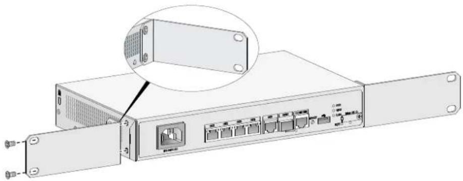
- Use M6 screws to attach the mounting brackets on the router to the front rack posts, as shown in Figure 8.
Figure 8 Securing the router to the rack
Grounding the router

CAUTION:
- Correctly connecting the grounding cable is crucial to lightning protection and EMI protection. When you install and use the router, first ground the router reliably.
- Ensure a minimum resistance of 5 ohms between the router and the ground.
The router provides only a ring terminal. No grounding cable is provided with the router. Purchase a grounding cable yourself.
Grounding the router with a grounding strip
- Remove the grounding screw from the grounding hole in the chassis.
- Use the grounding screw to attach the ring terminal of the grounding cable to the grounding hole.
- Use a screwdriver to fasten the grounding screw.
- Connect the other end of the grounding cable to the grounding strip.
Figure 9 Connecting the grounding cable to the router
Grounding the router by burying a grounding conductor in the earth ground
If the installation site does not have any grounding strips, but earth ground is available, hammer a 0.5 m (1.64 ft) or longer angle iron or steel tube into the earth ground to act as a grounding conductor.
Weld the yellow-green grounding cable to the angle iron or steel tube and treat the joint for corrosion protection.
Figure 10 Grounding the router by burying a grounding conductor in the earth ground
Installing a 4G SIM card (JH296A/JH297A/JH298A/JH299A)

CAUTION:
- Do not hot-swap a 4G SIM card.
- To avoid damaging the SIM card slot, do not use excessive force when installing a 4G SIM card.
To install a 4G SIM card:
- Remove the screw on the 4G SIM card slot cover and take off the cover.
- Insert the 4G SIM card into the SIM card slot along the guide rails.
- Reinstall the cover and fasten the screw on the cover.
Figure 11 Installing a 4G SIM card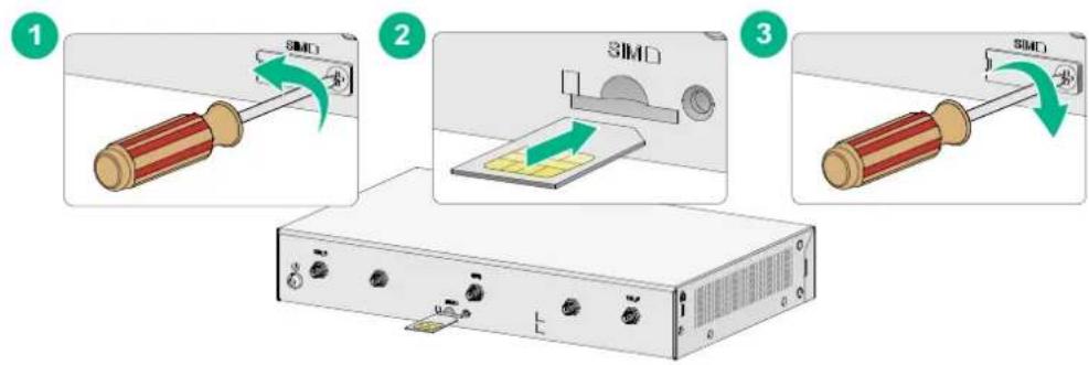
Installing a 4G SIM card (JH373A)

CAUTION:
- To avoid damage to the 4G SIM card holder, do not use excessive force when installing the 4G SIM card.
- Do not hot-swap a 4G SIM card.
To install a 4G SIM card:
- Remove the screw of the 4G SIM card socket cover on the router bottom and take off the cover.
Figure 12 Removing the 4G SIM card socket cover
- Install SIM 1 and SIM 2.
Figure 13 Install SIM 1 and SIM 2.


- Push the 4G SIM card holder in the direction marked "OPEN" so the holder projects upwards. Do not insert the 4G SIM card to the card holder before projecting the card holder up or lift the holder forcibly.
Figure 14 Incorrect installations

- Insert the 4G SIM card along the slide rails to the holder.
- Put down the holder and push the holder in the direction marked "LOCK" to lock the card in position.
Figure 15 Installing the 4G SIM card


- Position the 4G SIM card socket cover and fasten the screws on the cover.
Figure 16 Installing the 4G SIM card socket cover
Installing a Micro SD card

CAUTION:
To avoid damaging the Micro SD card slot, do not use excessive force when you install a Micro SD card.
Only the JH296A, JH297A, JH298A and JH299A routers support Micro SD cards.
To install a Micro SD card:
- Remove the screw on the Micro SD card slot cover and take off the cover.
- Insert the Micro SD card into the Micro SD card slot along the guide rails.
- Reinstall the cover and fasten the screw on the cover.
Figure 17 Installing a Micro SD card 1
2
3

Installing a 4G antenna
Only the JH298A, JH299A and JH373A routers support 4G antennas.
To install a 4G antenna:
- Change the angle of the antenna orientation from vertical to horizontal.
- Attach the 4G antenna to the 4G antenna port on the router. Do not over-tighten the antenna to avoid damage.
For better signal receiving, change the antenna orientation to vertical.
Figure 18 Installing 4G antennas (JH298A/JH299A)
Figure 19 Installing 4G antennas (JH373A)
Connecting a 4G antenna extension cable to a 4G router
Only the JH373A router supports a 4G antenna extension cable.
A 4G antenna extension cable is not provided with the router. To use a 4G antenna extension cable, purchase it separately.
To install a 4G antenna extension cable:
- Thread the male connector of the cable through the hole on the bracket, and use screws (from behind the bracket) to secure the male connector to the bracket.
- Change the angle of the antenna orientation from vertical to horizontal.
- Attach the antenna to the male connector of the cable.
- Attach the female connector of the cable to the router.
Figure 20 Installing the 4G antenna extension cable to a 4G router
Installing a WLAN antenna
Only the JH297A, JH298A, and JH299A routers support WLAN antennas.
To install a WLAN antenna:
- Change the angle of the antenna orientation from vertical to horizontal.
- Attach the antenna to the WLAN antenna port on the router. Do not over-tighten the antenna to avoid damage. For better signal receiving, change the antenna orientation to vertical.
Figure 21 Installing WLAN antennas
Connecting Ethernet interface cables
- Connect one end of the cable to an Ethernet port on the router.
- Connect the other end of the cable to the Ethernet port on a host.
- Examine the port LEDs on the router. For more information about the LEDs, see "LED description."
Figure 22 Connecting an Ethernet cable
Connecting the console cable and setting terminal parameters
Connecting the console cable

CAUTION:
The serial ports on PCs do not support hot swapping. To connect a PC to an operating router, first connect the PC end. To disconnect a PC from an operating router, first disconnect the router end.
To connect the console cable:
- Select a configuration terminal, which can be an ASCII terminal with an RS232 serial port or a PC. (A PC is more commonly used.)
- Connect the DB-9 connector (female) of the console cable to the RS-232 serial port on the configuration terminal and the RJ-45 connector to the console port of the router.
NOTE:
If the configuration terminal does not have an RS-232 serial port, a serial adapter is required to connect the console cable to a USB port on the terminal.
Figure 23 Connecting the console cable
Setting configuration terminal parameters
To access the device through the console port, you must run a terminal emulator program (HyperTerminal, PuTTY, or Tera Term) on the configuration terminal. For information about using a terminal emulator program, see the program's user guide.
The following are the required terminal settings:
• Baud rate—9600. • Data bits—8. • Stop bits—1. • Parity—none. • Flow control—none.
Connecting the power cord
To connect an AC power:
- Make sure the router is reliably grounded.
- Connect one end of the AC power cord to the AC power receptacle on the router, and connect the other end to the AC power source.
Figure 24 Connecting the power cord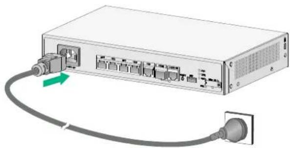
To connect a power adapter:
- Make sure the router is reliably grounded.
- Connect the power adapter to an AC power source.
- Connect the DC plug of the power adapter to the DC-input receptacle on the router.
Figure 25 Connecting a power adapter
Verifying the installation
After you complete the installation, verify the following information:
• There is enough space around the router for heat dissipation. • The router is securely installed. • Antennas and USB devices are installed correctly. • The router and power source are reliably grounded. • The power source is as required by the router. • The router is connected correctly to the configuration terminal and other devices. Parameters are configured correctly on the configuration terminal.
Accessing the router for the first time
Powering on the router

WARNING!
Before powering on the router, locate the power source switch so that you can cut off power promptly in case of an emergency.
To power on the router:
- Turn on the switch for the power source.
- Turn on the power switch on the router.
Observing the startup process
The router first initializes its memory at startup. Then it runs the extended BootWare. Observe the information displayed on the configuration terminal:
System is starting...
Press Ctrl+D to access BASIC-BOOTWARE MENU...
Booting Normal Extended BootWare
The Extended BootWare is self-decompressing....Done.
*
*
HPE MSR954 BootWare, Version 9.00
*
******************************************************************************************
Copyright (c) 2010-2016 Hewlett Packard Enterprise Development LP
Compiled Date : Jan 2 2016
CPU ID : 0x1
Memory Type : DDR3 SDRAM
Memory Size : 1024MB
Flash Size : 2MB
Nand Flash size : 256MB
CPLD Version : 2.0
PCB Version : 3.0
BootWare Validating...
Press Ctrl+B to access EXTENDED-BOOTWARE MENU...
Loading the main image files...
Loading file flash:/msr954-cmw710-system-r0305.bin....Done.
Loading file flash:/msr954-cmw710-security-r0305.bin...Done.
Loading file flash:/msr954-cmw710-voice-r0305.bin....Done.
Loading file flash:/msr954-cmw710-data-r0305.bin....Done.
Loading file flash:/msr954-cmw710-boot-r0305.bin....Done.
Image file flash:/msr954-cmw710-boot-r0305.bin is self-decompressing.....Done. System image is starting...
Startup configuration file does not exist. Performing automatic configuration... Press CTRL_D to break.
Automatic configuration attempt: 1.
Not ready for automatic configuration: no interface available.
Waiting for the next...
Automatic configuration is aborted.
Line aux0 is available.
Press ENTER to get started. Press Enter and the system displays the following prompt: This prompt indicates that the router has entered user view and is ready to configure.
Power-on check
After powering on the router, check the following items:
- The LEDs on the front panel are normal, as described in "LED description."
- The configuration terminal displays information correctly. You can see the startup window on the local configuration terminal. For more information, see "Observing the startup process."
- After completing the POST, the system prompts you to press Enter. When the command line prompt appears, the router is ready to configure.
Configuring basic settings for the router
After the router is powered on for the first time, configure basic settings for the router. For more information, see HPE FlexNetwork MSR Router Series Configuration Guides(V7) and HPE FlexNetwork MSR Router Series Command References(V7).
Troubleshooting
IMPORTANT:
- The barcode on the router chassis contains product information that must be provided to local sales agent when you return a faulty router for repair.
- Keep the tamper-proof seal on a mounting screw on the chassis cover intact, and if you want to open the chassis, contact Hewlett Packard Enterprise for permission. Otherwise, Hewlett Packard Enterprise shall not be liable for any consequence.
Power supply failure
Symptom
The router cannot be powered on and the LEDs on the front panel are off.
Solution
To resolve the problem:
- Power off the router
- Verify that the power cord connects the router to the power source correctly.
- Verify that the power source is operating correctly.
- Verify that the power cord is in good condition.
- If the problem persists, contact Hewlett Packard Enterprise Support.
No display on the configuration terminal
Symptom
The configuration terminal does not have display when the router is powered on.
Solution
To resolve the problem:
- Verify that the power system is operating correctly.
- Verify that the console cable is connected correctly to the specified serial port on the configuration terminal.
- Verify that the following settings are configured for the terminal:
Baud rate: 9,600. Data bits: 8. Parity: none. Stop bits: 1. Flow control: none. Emulation: VT100.
- Verify that the console cable is in good condition.
- If the problem persists, contact Hewlett Packard Enterprise Support.
Garbled display on the configuration terminal
Symptom
The configuration terminal has garbled display when the router is powered on.
Solution
To resolve the problem:
- Verify that the following settings are configured for the terminal:
Baud rate: 9,600. Data bits: 8. Parity: none. Stop bits: 1. Flow control: none.
- If the problem persists, contact Hewlett Packard Enterprise Support.
No response from the serial port
Symptom
The serial port on the router does not respond
Solution
To resolve the problem:
- Verify that the serial cable is in good condition and the serial port settings are correct.
- If the problem persists, contact Hewlett Packard Enterprise Support.
3G/4G SIM card and 4G antenna failures
Symptom
After a 3G/4G SIM card and 4G antennas are installed on the router and the router is powered on, the corresponding LEDs on the front panel indicate operation failure.
Solution
To resolve the problem:
- Verify that the 3G/4G SIM card has been correctly installed and makes good contact with the card socket.
- Verify that the 3G/4G SIM card and the card socket use the same wireless standard.
- Verify that the 4G antenna is correctly installed.
- Verify that the 3G/4G SIM card, card socket, and 4G antenna are in good condition.
- Verify that the network provided by NSP is running correctly.
- If the problem persists, contact Hewlett Packard Enterprise Support.
Restoring the factory settings
Scenario 1
Symptom
When you replace the router, the router password is lost. As a result, you cannot log in to the router and do not know the router configuration.
Solution
Because the router is replaced, you do not need to save the configuration of the router. In this case, you can press the Reset button for more than 4 seconds to reboot the router and restore the factory settings. Then, you can use the username and password shipped with the router to log in to the router.
When the router configuration must be saved and you have a console cable, you can log in to the router from the BootWare menu.
Scenario 2
Symptom
After the configuration is modified, network connectivity is lost. When you check the configuration, it is very complicated and it is hard to locate the errors. In this case, you must configure the router again.
Solution
If you have not saved any configuration, you can reboot the router by pressing the Reset button for a short time or power off the router.
If you have saved the configuration, delete the configuration file at the CLI, and press the Reset button to restore the factory settings.
Scenario 3
Symptom
The router crashes.
Solution
Press the Reset button for a short time to reboot the router.
Reset button usage guidelines
The router provides a Reset button. To reboot the router, use a paper clip to press the Reset button for a short time. To reboot the router and restore the factory settings, use a paper clip to press the Reset button for more than 4 seconds.
Figure 26 Reset button
Appendix A Chassis views and technical specifications
Chassis views
The figures in this appendix are for illustration only.
JH296A
Figure 27 Front view
(1) AC power receptacle (2) Gigabit Ethernet LAN ports (GE1 to GE4)
(3) Gigabit Ethernet WAN port (GE0)
(4) Gigabit fiber port (SFP5) (5) Console port (6) USB port
(7) Micro SD card slot (8) USB port (9) Reset button (RESET)
Figure 28 Rear view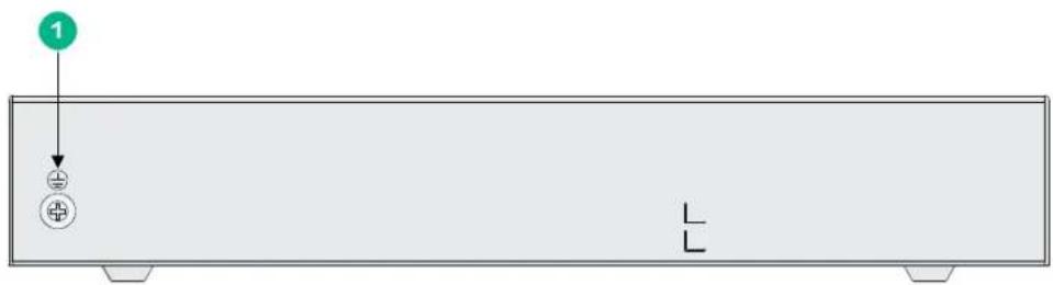
(1) Grounding screw
Figure 29 Front view
(1) AC power receptacle (2) Gigabit Ethernet LAN ports (GE1 to GE4) (3) Gigabit Ethernet WAN port (GE0) (4) Gigabit fiber port (SFP5) (5) Console port (6) USB port (7) Micro SD card slot (8) USB port (9) Reset button (RESET)
Figure 30 Rear view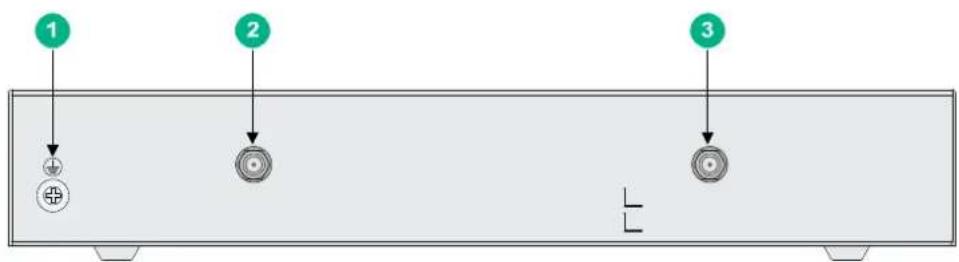
(1) Grounding screw (2) 2.4G WLAN antenna port (3) 2.4G WLAN antenna port
JH298A
Figure 31 Front view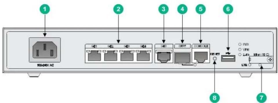
(1) AC power receptacle (2) Gigabit Ethernet LAN ports (GE1 to GE4) (3) Gigabit Ethernet WAN ports (GE0) (4) Gigabit fiber port (SFP5) (5) Console port (6) USB port (7) Micro SD card slot (8) Reset button (RESET)
Figure 32 Rear view
(1) Grounding screw (2) LTE antenna port 1 (3) 2.4G WLAN antenna port (4) 4G SIM card slot (5) 2.4G WLAN antenna port (6) LTE antenna port 2
JH299A
Figure 33 Front view
(1) AC power receptacle (2) Gigabit Ethernet LAN ports (GE1 to GE4) (3) Gigabit Ethernet WAN port (GE0) (4) Gigabit fiber port (SFP5) (5) Console port (6) USB port (7) Micro SD card slot (8) Reset button (RESET)
Figure 34 Rear view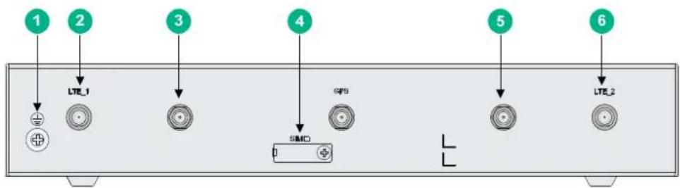
(1) Grounding screw (2) LTE antenna port 1 (3) 2.4G WLAN antenna port (4) 4G SIM card slot (5) 2.4G WLAN antenna port (6) LTE antenna port 2
Figure 35 Front view
(1) 4G antenna auxiliary connector (DIV1) (2) USB port
(3) Reset button (RESET) (4) 4G antenna main connector (MAIN1)
Figure 36 Rear view
(1) Serial port (2) 4G antenna main connector (MAIN2) (3) 4G antenna auxiliary connector (DIV2)
(4) Power adapter receptacle (5) Console/AUX port (CON/AUX) (6) Gigabit Ethernet WAN port (GE0)
(7) Gigabit Ethernet LAN ports (8) Grounding screw (GE1 to GE4)
Technical specifications
Table 6 Router specifications
| Item | JH296A | JH297A | JH298A | JH299A | JH373A |
| Console | port | 1 | 1 | 1 | 1 |
| USB | port | 2 | 2 | 1 | 1 |
| GE | WAN | port | 1 | 1 | 1 |
| GE | SFP | port | 1 | 1 | 1 |
| GE | LAN | port | 4 | 4 | 4 |
| Serial | port | N/A | N/A | N/A | N/A |
| Memory | 1 GB DDR3 | 1 GB DDR3 | 1 GB DDR3 | 1 GB DDR3 | 1 GB DDR3 |
| Flash | 256 MB | 256 MB | 256 MB | 256 MB | 256MB |
| Dimensions (H × W × D) (excluding rubber feet and mounting brackets) | 43.6 × 266 × 161 mm (1.72 × 10.47 × 6.34 in) | 43.6 × 266 × 161 mm (1.72 × 10.47 × 6.34 in) | 43.6 × 266 × 161 mm (1.72 × 10.47 × 6.34 in) | 43.6 × 266 × 161 mm (1.72 × 10.17 × 6.34 in) | 44.2 × 300 × 200 mm (1.74 × 11.81 × 7.87 in) |
| AC input voltage | 100 VAC to 240 VAC @ 50 Hz/60 Hz | 100 VAC to 240 VAC @ 50 Hz/60 Hz | 100 VAC to 240 VAC @ 50 Hz/60 Hz | 100 VAC to 240 VAC @ 50 Hz/60 Hz | 100 VAC to 240 VAC @ 50 Hz/60 Hz |
| Max. AC power 15 W 15 W 15 W 15 W 24 W | |||||
| Operating temperature | 0°C to 45°C (32°F to 113°F) | 0°C to 45°C (32°F to 113°F) | 0°C to 45°C (32°F to 113°F) | 0°C to 45°C (32°F to 113°F) | 0°C to 45°C (32°F to 113°F) |
| Relative humidity (non-condensing) | 5% to 90% 5% to 90% 5% to 90% 5% to 90% 5% to 90% | ||||
Table 7 4G antenna specifications
| Item | Specification |
| Frequency range 698-960 MHz / 1.71-2.70 GHz | |
| Voltage Standing Wave Ratio (VSWR) ≤ 2.5:1 | |
| Input impedance 50 ohms | |
| Gain | 2 |
| Max power 5 W | |
| Input port TNC male | |
| Length 21.4 cm (8.43 in) | |
| Color | Black |
| Weight 50 g (1.76 oz) | |
| Operating temperature -40°C to +85°C (-40°F to +185°F) | |
dBi
Table 8 WLAN antenna specifications
| Item | Specification |
| Frequency range 2.4 to 2.5 GHz | |
| Voltage standing wave ratio (VSWR) | 1.92:1 |
| Input impedance | 50 ohms |
| Gain | 2 dBi |
| Max power | 1 W |
| Input port | RSMA |
| Length | 115 mm (4.53 in) |
| Color | Black |
| Weight | 25 g (0.88 oz ) |
| Operating temperature | -10°C to +60°C (14°F to 140°F) |
Appendix B LEDs
LEDs
JH296A
Figure 37 Front panel LEDs
(1) GE port yellow LED (2) GE port green LED (3) System status LED (SYS) (4) Micro SD card LED (5) VPN status LED (6) SFP port LED
JH297A
Figure 38 Front panel LEDs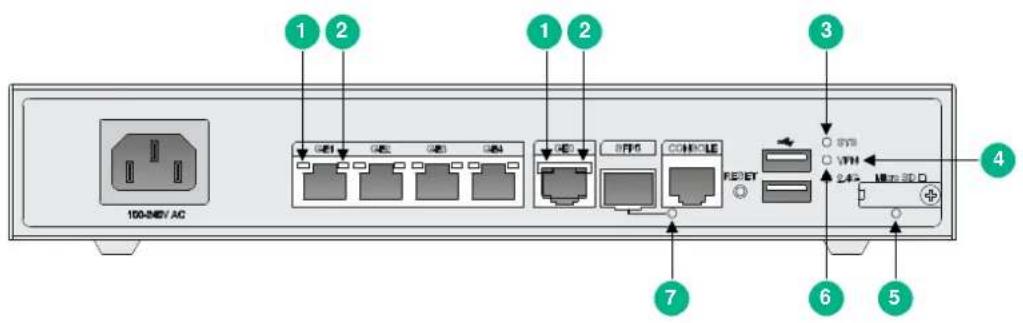
(1) GE port yellow LED (2) GE port green LED (3) System status LED (SYS) (4) VPN status LED (5) Micro SD card LED (6) 2.4G WLAN LED (7) SFP port LED
JH298A
Figure 39 Front panel LEDs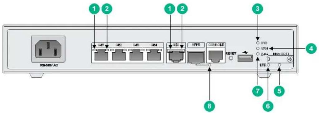
(1) GE port yellow LED (2) GE port green LED (3) System status LED (SYS) (4) VPN status LED (5) Micro SD card LED (6) LTE LED (7) 2.4G WLAN LED (8) SFP port LED
JH299A
Figure 40 Front panel LEDs
(1) GE port yellow LED (2) GE port green LED (3) System status LED (SYS) (4) VPN LED (5) Micro SD card LED (6) LTE LED (7) 2.4G WLAN LED (8) SFP port LED
Figure 41 Front panel LEDs
(1) System status LED (SYS) (2) VPN status LED (VPN) (3) 4G status LED (WWAN1)
(4) Received 4G signal strength indication LED (RSSI1) (5) 4G status LED (WWAN2) (6) Received 4G signal strength indication LED (RSSI2)
Figure 42 Rear panel LEDs
(1) Serial port link status LED (LINK) (2) Serial port data transmission status LED (ACT) (3) GE port status LED (yellow) (4) GE port status LED (green)
LED description
| LED | Status | Description | |
| GE port LEDs | Green LED | Steady green A 1000 Mbps link is present. | |
| Flashing green | Data is being received or transmitted at 1000 Mbps. | ||
| Off No 1000 Mbps link is present. | |||
| Yellow LED | Steady yellow A 10/100 Mbps link is present. | ||
| Flashing yellow | Data is being received or transmitted at 10/100 Mbps | ||
| Off No 10/100 Mbps link is present. | |||
| LED | Status | Description |
| System status LED (SYS) | Steady green The SDRAM is performing self-test. | |
| Flashing green (8 Hz) | The system software image is being copied and decompressed. | |
| Flashing green (1 Hz) | Comware has started with the configuration file and the router has booted up. | |
| Flashing yellow (1 Hz) The SDRAM has failed the self-test. | ||
| Flashing yellow (8 Hz) The extended segment does not exist. | ||
| Steady yellow The system software image does not exist. | ||
| Off | No power input, or exceptions have occurred. | |
| VPN status LED (VPN) | Steady on | A minimum of one IPSec VPN tunnel is present. |
| Off No IPSec VPN tunnel is present. | ||
| Micro SD card LED | Steady green | The Micro SD card is present and has passed the test. |
| Flashing green (8 Hz) | The system is accessing the Micro SD card. Do not remove the card. | |
| Off | No Micro SD card is inserted or the Micro SD card is installed incorrectly. | |
| LTE LED | Steady green A 4G link is present. | |
| Flashing green (8 Hz) | Data is being received or transmitted on a 4G link. | |
| Steady yellow A 3G link is present. | ||
| Flashing yellow (8 Hz) | Data is being received or transmitted on a 3G link. | |
| Off | No 3G/4G link is present or no 4G modem is installed. | |
| 2.4G WLAN status LED | Steady green A 2.4G WLAN link is present. | |
| Flashing green | Data is being received or transmitted on a 2.4G WLAN link. | |
| Off No 2.4G WLAN link is present. | ||
| SFP port LED | Steady green A 1000 Mbps link is present. | |
| Flashing green | Data is being received or transmitted at 1000 Mbps. | |
| Steady yellow A 10/100 Mbps link is present. | ||
| Flashing yellow | Data is being received or transmitted at 10/100 Mbps. | |
| Off No link is present. | ||
| 4G status LED (WWAN) | Off | No link is present or the router is operating in 2G mode. |
| Steady green | The router has been connected to the wireless network and is operating in 4G mode. | |
| Flashing green (8 Hz) | Data is being received or transmitted. The router is operating in 4G mode. | |
| Steady yellow | The router has been connected to the wireless network and is operating in 3G mode. | |
| Flashing yellow (8 Hz) | Data is being received or transmitted. The router is operating in 3G mode. | |
| Received 4G signal strength indication LED (RSSI) | Off Weak or no signal. | |
| Steady green Strong signal. | ||
| Flashing green (8 Hz) Middle or low signal. | ||
| Serial port data transmission status LED (ACT) | Off No data is being received or transmitted. | |
| Flashing green Data is being received or transmitted. | ||
| Serial port link status LED (LINK) | Off No link is present. | |
| Steady green A link is present. | ||
Document conventions and icons
Conventions
This section describes the conventions used in the documentation.
Port numbering in examples
The port numbers in this document are for illustration only and might be unavailable on your device.
Command conventions
| Convention | Description |
| Boldface | Bold text represents commands and keywords that you enter literally as shown. |
| Italic | Italic text represents arguments that you replace with actual values. |
| [ ] Square brackets | enclose syntax choices (keywords or arguments) that are optional. |
| {x | y | ... } | Braces enclose a set of required syntax choices separated by vertical bars, from which you select one. |
| [x | y | ... ] | Square brackets enclose a set of optional syntax choices separated by vertical bars, from which you select one or none. |
| {x | y | ... }* | Asterisk marked braces enclose a set of required syntax choices separated by vertical bars, from which you select at least one. |
| [x | y | ... ]* | Asterisk marked square brackets enclose optional syntax choices separated by vertical bars, from which you select one choice, multiple choices, or none. |
| &<1-n> | The argument or keyword and argument combination before the ampersand (&) sign can be entered 1 to n times. |
| # A line that starts with a pound (#) sign is comments. | |
GUI conventions
| Convention | Description |
| Boldface | Window names, button names, field names, and menu items are in Boldface. For example, the New User window appears; click OK. |
| > | Multi-level menus are separated by angle brackets. For example, File > Create > Folder. |
Symbols
| Convention | Description |
| WARNING! | An alert that calls attention to important information that if not understood or followed can result in personal injury. |
| CAUTION: | An alert that calls attention to important information that if not understood or followed can result in data loss, data corruption, or damage to hardware or software. |
| IMPORTANT: | An alert that calls attention to essential information. |
| NOTE: | An alert that contains additional or supplementary information. |
| TIP: | An alert that provides helpful information. |
Network topology icons
| Convention | Description |
 | Represents a generic network device, such as a router, switch, or firewall. |
 | Represents a routing-capable device, such as a router or Layer 3 switch. |
 | Represents a generic switch, such as a Layer 2 or Layer 3 switch, or a router that supports Layer 2 forwarding and other Layer 2 features. |
 | Represents an access controller, a unified wired-WLAN module, or the access controller engine on a unified wired-WLAN switch. |
 | Represents an access point. |
| -ZYW7] | Represents a wireless terminator unit. |
 | Represents a wireless terminator. |
 | Represents a mesh access point. |
 | Represents omnidirectional signals. |
 | Represents directional signals. |
 | Represents a security product, such as a firewall, UTM, multiservice security gateway, or load balancing device. |
 | Represents a security card, such as a firewall, load balancing, NetStream, SSL VPN, IPS, or ACG card. |
Support and other resources
Accessing Hewlett Packard Enterprise Support
- For live assistance, go to the Contact Hewlett Packard Enterprise Worldwide website: www.hpe.com/assistance
- To access documentation and support services, go to the Hewlett Packard Enterprise Support Center website: www.hpe.com/support/hpesc
Information to collect
• Technical support registration number (if applicable) - Product name, model or version, and serial number - Operating system name and version - Firmware version - Error messages • Product-specific reports and logs - Add-on products or components • Third-party products or components
Accessing updates
- Some software products provide a mechanism for accessing software updates through the product interface. Review your product documentation to identify the recommended software update method. • To download product updates, go to either of the following:
- Hewlett Packard Enterprise Support Center Get connected with updates page: www.hpe.com/support/e-updates
- Software Depot website: www.hpe.com/support/softwaredepot
- To view and update your entitlements, and to link your contracts, Care Packs, and warranties with your profile, go to the Hewlett Packard Enterprise Support Center More Information on Access to Support Materials page: www.hpe.com/support/AccessToSupportMaterials
IMPORTANT:
Access to some updates might require product entitlement when accessed through the Hewlett Packard Enterprise Support Center. You must have an HP Passport set up with relevant entitlements.
Websites
| Website | Link |
| Networking websites | |
| Hewlett Packard Enterprise Information Library for Networking | www.hpe.com/networking/resourcefinder |
| Hewlett Packard Enterprise Networking website | www.hpe.com/info/networking |
| Hewlett Packard Enterprise My Networking website | www.hpe.com/networking/support |
| Hewlett Packard Enterprise My Networking Portal | www.hpe.com/networking/mynetworking |
| Hewlett Packard Enterprise Networking Warranty | www.hpe.com/networking/warranty |
| General websites | |
| Hewlett Packard Enterprise Information Library | www.hpe.com/info/enterprise/docs |
| Hewlett Packard Enterprise Support Center | www.hpe.com/support/hpesc |
| Hewlett Packard Enterprise Support Services Central | ssc.hpe.com/portal/site/ssc/ |
| Contact Hewlett Packard Enterprise Worldwide | www.hpe.com/assistance |
| Subscription Service/Support Alerts | www.hpe.com/support/e-updates |
| Software Depot www.hpe.com/support/softwaredepot | |
| Customer Self Repair (not applicable to all devices) | www.hpe.com/support/selfrepair |
| Insight Remote Support (not applicable to all devices) | www.hpe.com/info/insightremotesupport/docs |
Customer self repair
Hewlett Packard Enterprise customer self repair (CSR) programs allow you to repair your product. If a CSR part needs to be replaced, it will be shipped directly to you so that you can install it at your convenience. Some parts do not qualify for CSR. Your Hewlett Packard Enterprise authorized service provider will determine whether a repair can be accomplished by CSR.
For more information about CSR, contact your local service provider or go to the CSR website:
www.hpe.com/support/selfrepair
Remote support
Remote support is available with supported devices as part of your warranty, Care Pack Service, or contractual support agreement. It provides intelligent event diagnosis, and automatic, secure submission of hardware event notifications to Hewlett Packard Enterprise, which will initiate a fast and accurate resolution based on your product's service level. Hewlett Packard Enterprise strongly recommends that you register your device for remote support.
For more information and device support details, go to the following website:
www.hpe.com/info/insightremotesupport/docs
Documentation feedback
Hewlett Packard Enterprise is committed to providing documentation that meets your needs. To help us improve the documentation, send any errors, suggestions, or comments to Documentation Feedback (docsfeedback@hpe.com). When submitting your feedback, include the document title, part number, edition, and publication date located on the front cover of the document. For online help content, include the product name, product version, help edition, and publication date located on the legal notices page.
Index
Numerics
4G antenna
technical specifications, 33
A
AC
troubleshooting power supply failure, 25
accessories (installation), 4
Appendix
A chassis views and technical
specifications, 29
B LEDs, 34
C
cable
connecting console cable, 20
installing interface cable, 20
troubleshooting no response from serial port, 26
chassis
cooling and ventilation, 3
chassis views, 29
JH296A, 29
JH297A, 30
JH298A, 30
JH299A, 31, 32
cleanliness (installation site), 2
configuring
basic settings for router, 24
connecting
console cable, 20
power cord, 21
console
connecting cable, 20
power-on check, 23
setting terminal parameters, 21
troubleshooting garbled terminal display, 26
cooling requirements (installation site), 3
D
DC power cord, 21
dust (installation site), 2
E
electrical
connecting power cord, 21
grounding router with buried grounding conductor, 13
grounding router with grounding strip, 13
grounding the router, 12
powering on the router, 22
electricity
electricity
electrical cooling requirements, 3
electromagnetic interference. Use EMI
EMI prevention, 3
safety recommendations, 1
troubleshooting power supply failure, 25
EMI prevention, 3
environment
installation site, 2
site cleanliness, 2
site cooling requirements, 3
site dust concentration, 2
site gas saturation, 2
site humidity, 2
site temperature, 2
examining installation site, 2
F
factory settings
restoring, 27
G
garbled terminal display (troubleshooting), 26
gas (installation site), 2
grounding
buried grounding conductor, 13
EMI prevention, 3
grounding strip, 13
lightning protection, 3
router, 12
H
hardware
chassis cooling and ventilation, 3
grounding router with buried grounding
conductor, 13
grounding router with grounding strip, 13
grounding the router, 12
installation flowchart, 7
installing 3G/4G antenna extension cable, 19
installing 4G SIM card, 14, 14
installing WLAN antenna, 19
router installation, 7, 8
router wall installation, 9
router workbench installation, 8
humidity
installation site requirements, 2
|
installation flowchart, 7
Installing
3G/4G antenna extension cable, 19
installing
4G SIM card, 14, 14
accessories required, 4
cooling requirements, 3
EMI prevention, 3
interface cable, 20
lightning protection, 3
pre-installation checklist, 5
router, 7, 8
router on wall, 9
site cleanliness, 2
site examination, 2
site humidity, 2
site temperature, 2
tools required, 4
troubleshooting router installation, 25
verifying installation, 22
WLAN antenna, 19
interface
cable installation, 20
L
LED
JH296A, 34
JH297A, 34
JH298A, 35
JH299A, 35
LED description, 36
power-on check, 23
technical specifications, 34, 34
lightning
protection, 3
M
mounting
router on workbench, 8
N
network management
router installation, 7, 8
troubleshooting router installation, 25
no response from serial port (troubleshooting), 26
P
parameter (console terminal), 21
port (troubleshooting no response), 26
power cooling requirements, 3
power cord
AC power, 21
power supply
connecting power cord, 21
troubleshooting failure, 25
powering on (router), 22
power-on check, 23
pre-installation checklist, 5
preventing
EMI prevention, 3
procedure
configuring basic settings for router, 24
connecting console cable, 20
connecting power cord, 21
grounding router with buried grounding
conductor, 13
grounding router with grounding strip, 13
grounding the router, 12
installing 3G/4G antenna extension cable, 19
installing 4G SIM card, 14, 14
installing interface cable, 20
installing router on wall, 9
installing the router, 7, 8
installing WLAN antenna, 19
mounting router on workbench, 8
powering on the router, 22
restoring factory settings, 27
setting console terminal parameters, 21
startup process, 22
troubleshooting 3G/4G antenna failure, 26
troubleshooting 3G/4G SIM card and 3G/4G
antenna failures, 26
troubleshooting 3G/4G SIM card failure, 26
troubleshooting garbled terminal display, 26
troubleshooting no response from serial port, 26
troubleshooting power supply failure, 25
R
reset button
usage guidelines, 27
s
safety
caution and warning symbols, 1
electrical safety recommendations, 1
EMI prevention, 3
general recommendations, 1
installation site cleanliness, 2
installation site dust concentration, 2
installation site gas saturation, 2
installation site humidity, 2
installation site temperature, 2
lightning protection, 3
setting console terminal parameters, 21
site
cleanliness, 2
cooling requirements, 3
dust concentration, 2
examination, 2
gas saturation, 2
humidity, 2
temperature, 2
startup process, 22
T
technical specifications, 32
4G antenna, 33
LED, 34, 34
temperature
installation site requirements, 2
site cooling requirements, 3
terminal
setting console parameters, 21
troubleshooting garbled display, 26
tools (installation), 4
troubleshooting
3G/4G antenna failure, 26
3G/4G SIM card failure, 26
garbled terminal display, 26
no response from serial port, 26
power supply failure, 25
reset button usage guidelines, 27
restoring factory settings, 27
router installation, 25
U
usage guidelines
reset button, 27
V
ventilation (installation site), 3
verifying installation, 22
W
wall (router installation), 9
workbench (router installation), 8

- HPE FLEXNETWORK MSR 954 ROUTERS INSTALLATION GUIDE
- ACKNOWLEDGMENTS
- CONTENTS
- PREPARING FOR INSTALLATION
- INSTALLING THE ROUTER
- TROUBLESHOOTING
- APPENDIX A CHASSIS VIEWS AND TECHNICAL SPECIFICATIONS
- APPENDIX B LEDS
- DOCUMENT CONVENTIONS AND ICONS
- SUPPORT AND OTHER RESOURCES
- INDEX
- IMPORTANT
- SAFETY RECOMMENDATIONS
- SAFETY SYMBOLS
- GENERAL SAFETY RECOMMENDATIONS
- ELECTRICITY SAFETY
- ESD PREVENTION
- WARNING
- EXAMINING THE INSTALLATION SITE
- TEMPERATURE AND HUMIDITY
- CLEANLINESS
- COOLING
- EMI
- LIGHTNING PROTECTION
- INSTALLATION ACCESSORIES AND TOOLS
- PRE-INSTALLATION CHECKLIST
- INSTALLATION PREREQUISITES
- INSTALLATION FLOWCHART
- MOUNTING THE ROUTER ON A WORKBENCH
- MOUNTING THE ROUTER ON A WALL
- INSTALLING THE ROUTER IN A RACK
- CAUTION
- GROUNDING THE ROUTER
- GROUNDING THE ROUTER WITH A GROUNDING STRIP
- GROUNDING THE ROUTER BY BURYING A GROUNDING CONDUCTOR IN THE EARTH GROUND
- INSTALLING A 4G SIM CARD (JH296A/JH297A/JH298A/JH299A)
- INSTALLING A 4G SIM CARD (JH373A)
- INSTALLING A MICRO SD CARD
- INSTALLING A 4G ANTENNA
- CONNECTING A 4G ANTENNA EXTENSION CABLE TO A 4G ROUTER
- INSTALLING A WLAN ANTENNA
- CONNECTING ETHERNET INTERFACE CABLES
- CONNECTING THE CONSOLE CABLE AND SETTING TERMINAL PARAMETERS
- NOTE
- SETTING CONFIGURATION TERMINAL PARAMETERS
- CONNECTING THE POWER CORD
- VERIFYING THE INSTALLATION
- ACCESSING THE ROUTER FOR THE FIRST TIME
- POWERING ON THE ROUTER
- OBSERVING THE STARTUP PROCESS
- POWER-ON CHECK
- CONFIGURING BASIC SETTINGS FOR THE ROUTER
- POWER SUPPLY FAILURE
- SYMPTOM
- SOLUTION
- NO DISPLAY ON THE CONFIGURATION TERMINAL
- GARBLED DISPLAY ON THE CONFIGURATION TERMINAL
- NO RESPONSE FROM THE SERIAL PORT
- G/4G SIM CARD AND 4G ANTENNA FAILURES
- RESTORING THE FACTORY SETTINGS
- SCENARIO
- RESET BUTTON USAGE GUIDELINES
- CHASSIS VIEWS
- JH296A
- JH298A
- JH299A
- TECHNICAL SPECIFICATIONS
- LEDS
- JH297A
- LED DESCRIPTION
- CONVENTIONS
- PORT NUMBERING IN EXAMPLES
- COMMAND CONVENTIONS
- GUI CONVENTIONS
- SYMBOLS
- NETWORK TOPOLOGY ICONS
- ACCESSING HEWLETT PACKARD ENTERPRISE SUPPORT
- ACCESSING UPDATES
- WEBSITES
- CUSTOMER SELF REPAIR
- REMOTE SUPPORT
- DOCUMENTATION FEEDBACK
- NUMERICS
- A
- C
- D
- E
- F
- G
- H
- L
- M
- N
- P
- R
- S
- T
- U
- V
- W
Brand : HP
Model : FlexNetwork MSR954
Category : Router