417 - Access Point HP - Free user manual and instructions
Find the device manual for free 417 HP in PDF.

| Product Type | Wireless Access Point |
| Model | 417 |
| Brand | HP |
| Dimensions (approx.) | 200 x 150 x 30 mm |
| Weight (approx.) | 300 g |
| Power Supply | PoE (Power over Ethernet) or DC adapter (12V 1A) |
| Wireless Standards | IEEE 802.11a/b/g/n/ac |
| Frequency Bands | 2.4 GHz and 5 GHz |
| Maximum Data Rate | Up to 1200 Mbps |
| Antenna Type | Internal dual-band antennas |
| Number of SSIDs | Up to 8 |
| Security | WPA2-PSK, WPA3, 802.1X |
| Management | Web interface, SNMP, Telnet |
| Ports | 1 x 10/100/1000 Ethernet (PoE-in) |
| Operating Temperature | 0°C to 40°C |
| Humidity | 10% to 90% (non-condensing) |
| Mounting | Wall or ceiling mountable |
| LED Indicators | Power, LAN, Wireless |
| Care and Cleaning | Wipe with a soft, dry cloth. Avoid liquids. |
| Safety | Keep away from water and heat sources. Use only supplied power adapter. |
| Spare Parts & Repairability | No user-serviceable parts. Contact HP support for repairs. |
| General Information | Firmware updates available via HP website. Default credentials: admin/admin. |
Frequently Asked Questions - 417 HP
User questions about 417 HP
0 question about this device. Answer the ones you know or ask your own.
Ask a new question about this device
Download the instructions for your Access Point in PDF format for free! Find your manual 417 - HP and take your electronic device back in hand. On this page are published all the documents necessary for the use of your device. 417 by HP.
USER MANUAL 417 HP
HP 417 Single Radio 802.11n Unified Wired WLAN Walljack quick start guide
This quick start guide shows you how to install and get started using the HP 417 Single Radio 802.11n Unified Wired WLAN Walljack (RMN BJNGA-FB0003) JG971A (AM), JG972A (WW), JG973A (20 pack AM), JG974A (20 pack WW), hereafter referred to as the HP 417.
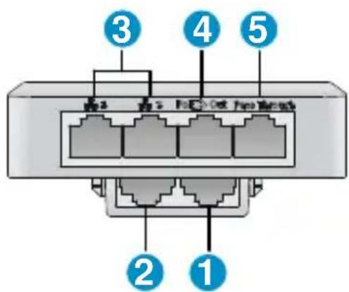
Hardware overview

natural_image
Blank white square with rounded corners, no text or symbols presentFront view
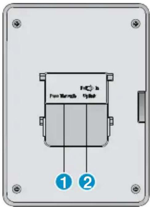
Back view
1: Pass Through port
2: Uplink port
Bottom views
3: Ethernet LAN ports 1 and 2
4: PoE Out Ethernet LAN port 3
5: Pass Through port
Package contents
The HP 417, mounting bracket, screws, MAC address label, and documentation.
Ports
- Three Ethernet ports: Auto-sensing 100Base-T Ethernet ports with RJ-45 connectors. One port provides IEEE 802.3af Power over Ethernet (PoE) to supply power to one device.
One Gigabit Ethernet uplink port: Auto-sensing 1000Base-T Ethernet port with RJ-45 connector.
• One pair of pass-through ports: Work with Cat5 cabling as well as an analog telephone cable.
Radio and antennas
The HP 417 supports IEEE 802.11b/g/n. It has two internal antennas (4.2 dBi) supporting 2x2 MIMO with two spatial streams at a rate of up to 300 Mbps.
Reset button
The reset button is accessible through a hole on the side panel of the HP 417. To reset the HP 417, insert a paper clip into the reset button hole, and press and quickly release the button. To reset the HP 417 to factory defaults, press and hold the button more than 5 seconds until the status LEDs (Power, Radio, and Uplink) flash, then release.
Status LEDs
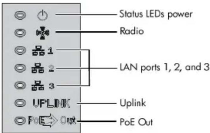
| Power | Uplink | Radio | LAN(1 to 3) | PoE | Description | |
| Off | Off | Off | Off | The AP has no power. | ||
| Steady orange | Off | Off | Off | The AP is starting up. | ||
| Flashing green once per second | Off | Off | Off | Off | The AP is looking for an IP address or building the list of VLANS on which to perform discovery. | |
| The power, uplink, and radio LEDs are flashing green in sequence. | Off | Off | The AP has obtained an IP address and is attempting to discover a controller. | |||
| Steady green | The uplink and radio LEDs are flashing green alternately. | Off | Off | The AP has found a controller and is attempting to establish a tunnel with it. | ||
| The power and uplink LEDs are alternately flashing green (slowly). | Off | Off | Off | The AP is performing Ethernet negotiation, and is waiting for the Ethernet link to come up. | ||
| Steady green | Off | Any | Any | The uplink interface is not connected or there is no network activity. | ||
| Steady green | Flashing green | Any | Any | Any | The uplink interface is transmitting or receiving data. | |
| Steady green | Any | Off | Any | The radio interface is disabled or there is no network activity. | ||
| Steady green | Any | Flashing green | Any | Any | The radio interface is transmitting or receiving data. | |
| Steady green | Any | Any | Off | The LAN interface is disabled or there is no network activity. | ||
| Steady green | Any | Any | Flashing green | Any | The LAN interface is transmitting or receiving data. | |
| Steady green | Any | Any | Any | No PoE device is connected. | ||
| Steady green | Any | Any | Any | Steady green | A PoE device is connected. | |
Powering the HP 417
The HP 417 can be powered by a PoE-enabled switch that provides 10/100 Mbps or 10/100/1000 Mbps Ethernet ports.
The HP 417 supports an 802.3af PoE PSE connection to one device on LAN port 3. This feature is dependent on the power source of the HP 417, as follows:
- Supports 802.3af class 1/2/3 PoE Out when the 803.3at (PoE+) power supply mode is used.
• Supports 802.3af class 1/2 PoE Out when the standard 803.3af power supply mode is used.
Important information to read before installing
Professional installation is required. For indoor installation only. Before installing or using the AP, consult with a professional installer trained in RF installation and knowledgeable in local regulations including building and wiring codes, safety, channel, power, and license requirements for the intended country. The end user is responsible for ensuring that installation and use comply with local safety and radio regulations.
To avoid possible bodily injury or equipment damage, read the following safety recommendations before you install an HP 417. The recommendations do not cover every possible hazardous condition.
• Install with six inches or more of clearance around the walljack.
- Keep the chassis clean and dust-free.
• Make sure the ground is dry and flat and anti-slip measures are in place.
- Do not place the AP in a moist area and avoid liquid surrounding the AP.
- Keep the chassis and installation tools away from walkways.
Installation
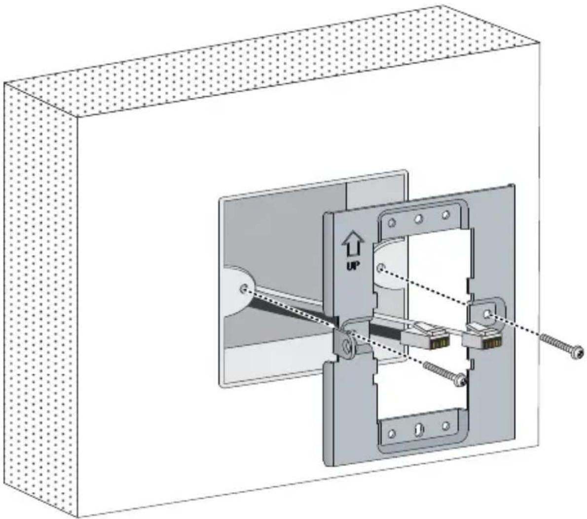
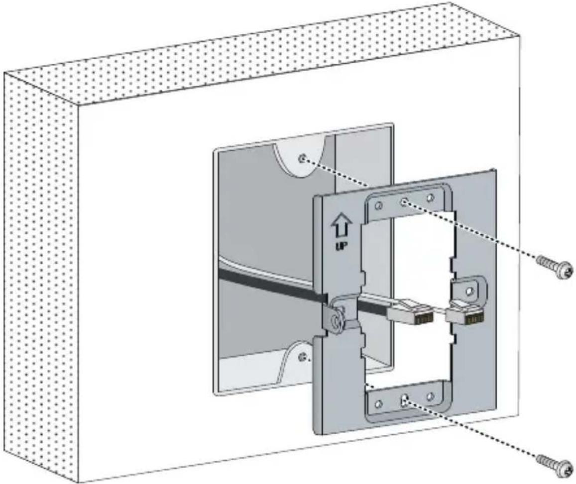
- Place the mounting bracket, with the UP arrow pointing up, on the electrical outlet box, and then use two of the supplied mounting screws to secure the bracket to the box.
The two long mounting screws are for a US electrical box. The two short mounting screws are for an EU electrical outlet box.
Long mounting screw

Short mounting screw
Figure 1 Securing the mounting bracket to an electrical outlet box (EU)
natural_image
Technical diagram of a mechanical assembly inside a rectangular frame, showing internal components and connection lines (no text or symbols)Figure 2 Securing the mounting bracket to an electrical outlet box (US)
natural_image
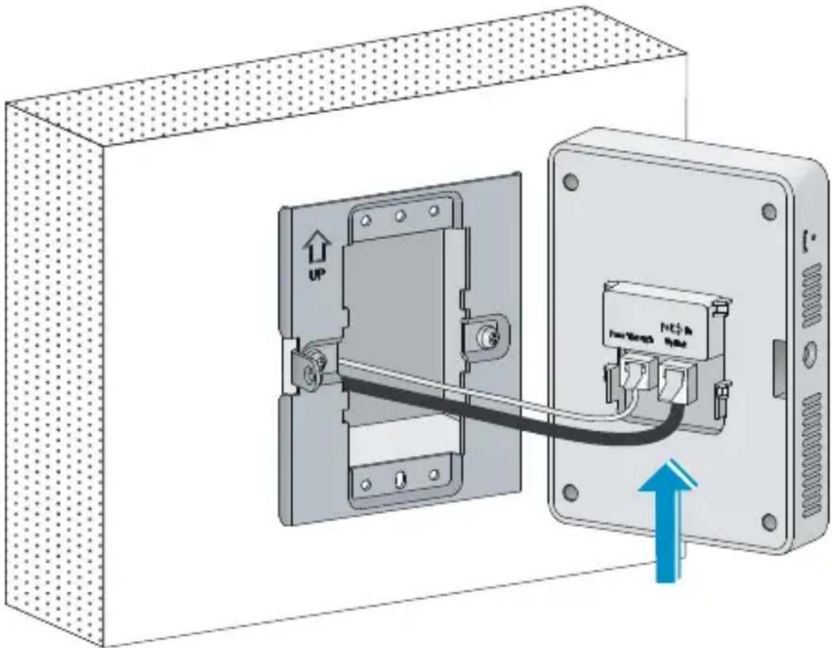
Technical diagram of a mechanical assembly with mounting holes and fasteners, no text or symbols present- Connect the network cable from the box to the RJ-45 Uplink port on the back of the HP 417. If required, also connect the cable providing support for pass-through devices to the Pass Through port on the back of the HP 417.
Figure 3 Connecting the network cable
natural_image
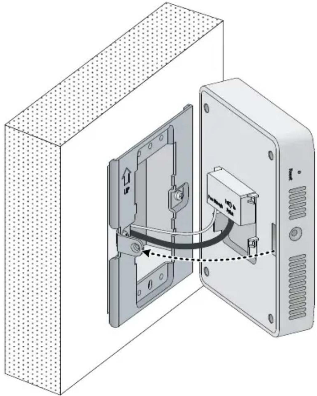
Diagram of an electrical enclosure with a cable and switch, showing internal components and directional arrows (no text or symbols)- Align the installation hole in the rear of the AP with the standout on the mounting bracket.
Figure 4 Aligning the installation hole
natural_image
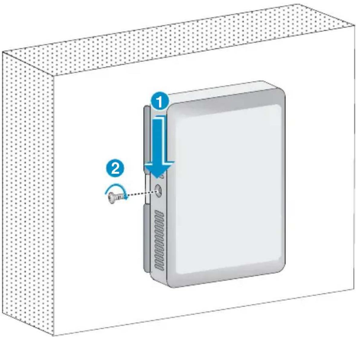
Diagram of an open computer case with internal components and a dashed line indicating connection (no text or symbols present)- Push the HP 417 onto the mounting bracket, and then slide it down until it is fully engaged. Then secure the AP to the bracket by using the Phillips-head screw or the security-head security Torx-10 screw.
Do not let go of the HP 417 until you confirm that it is securely in place.
Figure 5 Securing the AP
Provided access services
After the installation is complete, connect equipment to the HP 417 as follows:
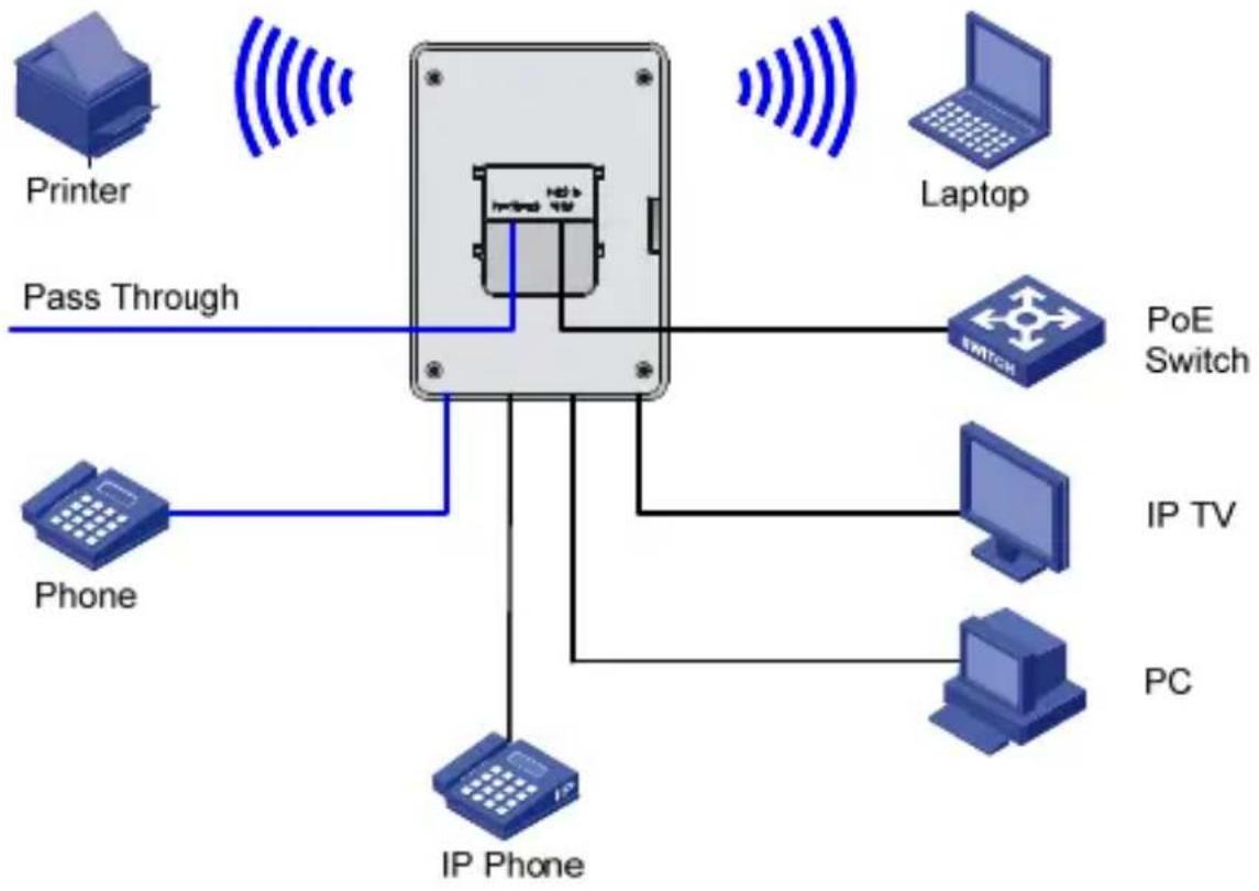
flowchart
graph TD
    A["Printer"] -->|Pass Through| B["Central Device"]
    C["Laptop"] -->|Pass Through| B
    D["Phone"] -->|Pass Through| B
    E["IP Phone"] -->|Pass Through| B
    F["POE Switch"] --> B
    G["IP TV"] --> B
    H["PC"] --> B
    B --> I["Switch"]
Technical support
For worldwide technical support information, see the HP support website at www.hp.com/networking/support.
Other regulatory information
For important safety, environmental, and regulatory information, see Safety and Compliance Information for Server, Storage, Power, Networking, and Rack Products, available at www.hp.com/support/Safety-Compliance-EnterpriseProducts.
FCC Notice
This device must not be co-located with any other transmitters except in accordance with FCC multi-transmitter product procedures.
Referring to the multi-transmitter policy, multiple-transmitter(s) and module(s) can be operated simultaneously without C2P.
This device will not permit operation on channels 120-128 for 802.11a, 802.11n, and 802.11ac modes that overlap the 5600-5650 MHz band.
A 20 cm minimum distance must be maintained between the antenna and the users for the host this module is integrated into. Under such configuration, the FCC radiation exposure limits set forth for a population/uncontrolled environment can be satisfied.
Any changes or modifications not expressly approved by the manufacturer could void the user's authority to operate this equipment.
Industry Canada Notice
CAN ICES-3 (B)/NMB-3(B)
This device complies with Industry Canada license-exempt RSS standard(s). Operation is subject to the following two conditions: (1) this device may not cause interference, and (2) this device must accept any interference, including interference that may cause undesired operation of the device.
Important Note: IC Radiation Exposure Statement: This equipment complies with IC RSS-102 radiation exposure limits set forth for an uncontrolled environment. This equipment should be installed and operated with minimum distance of 20 cm between the radiator and your body.
Class B (broadcasting
communication device for home use)
This device obtained EMC registration mainly for home use (Class B) and may be used in all areas.
Eurasian Economic Commission
HP 417 Single Radio 802.11n Unified Wired WLAN Walljack (JG972A)
Точка доступа HP 417 Single Radio 802.11n Устройство Unified Wired WLAN Walljack (JG972A)
Street, Palo Alto, California 94304-1185, U.S.A
Made In China
Изготовлено в Китае
Кытайда жасалған
Виготовлено в Китаї
Local Representatives
The HP 417 Access Point supports IEEE 802.11b/g/n, has two internal antennas supporting 2x2 MIMO spatial streams at a rate of up to 300 Mbps and is powered via PoE. The Access Point has 3 Auto-sensing 100 Base-T Ethernet ports, 1 Gigabit Ethernet uplink port and one pair of pass-through ports.
Обзор продукта
The manufacturing date is defined by the serial number.
CCYMBBBZZZ (HP serial number format for this product)
Valid date formats include:
Y (Y) = Year of Manufacture (Where Y indicates the year counting from within each new decade, with 2000 as the starting point. For example, 2 for 2002. The year 2010 is indicated by 0, 2011 by 1, and so forth. YY indicates the year using a base year of 2000. For example, 02 for 2002 and 12 for 2012)
M (M) = Month of Manufacture (For M, 1-9 for January to September, 0 for October, A for November, B for December. For MM, actual calendar month 1-12)
Дата изготовления
Environmental Conditions
Operating temperature: 32^ F to 115^ F ( 0^ C to 45^ C)
Operating relative humidity: 5% to 95%, noncondensing
Non-operating/Storage temperature: -40^ to +158^ ( -40^ to +70^ )
Non-operating/Storage relative humidity: 5% to 95%, noncondensing
Altitude: Up to 13,123 ft (4 km)
Physical characteristics
Dimensions: 120 × 86 × 35 mm ( 4.72 × 3.39 × 1.38 in)
Weight: 0.19 kg (6.70 oz)
Mounting position: Standard US or EU electrical box
Electrical characteristic
IEEE 802.3af and 802.3at PoE compliant for Gigabit Ethernet
Ports
A 10/100/1000 Mbps uplink Ethernet port that supports PoE In.
Three 10/100 Mbps downlink Ethernet ports, one of which supports PoE Out.
A pair of RJ-45 Pass Through ports.
Memory and processor
CPU
Single-core
@
Storage media Nor Flash 4MB, Nand Flash 128MB
Memory
DDR2
128MB
Performance
Radios
802.11
b/g/n
Radio operation modes Client access, Local mesh, Packet capture
AP operation modes Managed
Wi-Fi Alliance Certification b/g/n Wi-Fi Certified
Disposal of Waste Equipment by Users in Private Households

natural_image
Symbol of a trash bin crossed with no text or numbers, representing environmental restriction (no text present)This symbol means do not dispose of your product with your other household waste. Instead, you should protect human health and the environment by handing over your waste equipment to a designated collection point for the recycling of waste electrical and electronic equipment. For more information, please contact your household waste disposal service.
natural_image
Symbol of a trash bin crossed with no text or numbers, representing waste sorting or disposal (no text present)natural_image
Symbol of a trash bin crossed with no text or numbers, representing environmental restriction (no text present)natural_image
Symbol of a trash bin crossed with no text or numbers, representing waste sorting or disposal (no text present)© Copyright 2014 Hewlett-Packard Development Company, L.P. The information contained herein is subject to change without notice.
May 2014
Printed in China
Document part #5998-5825