KLR 3200 - Receiver Ashly - Free user manual and instructions
Find the device manual for free KLR 3200 Ashly in PDF.


User questions about KLR 3200 Ashly
0 question about this device. Answer the ones you know or ask your own.
Ask a new question about this device
Download the instructions for your Receiver in PDF format for free! Find your manual KLR 3200 - Ashly and take your electronic device back in hand. On this page are published all the documents necessary for the use of your device. KLR 3200 by Ashly.
USER MANUAL KLR 3200 Ashly
KLR 2000, KLR 3200, KLR 4000, KLR 5000
Operator Manual
text_image
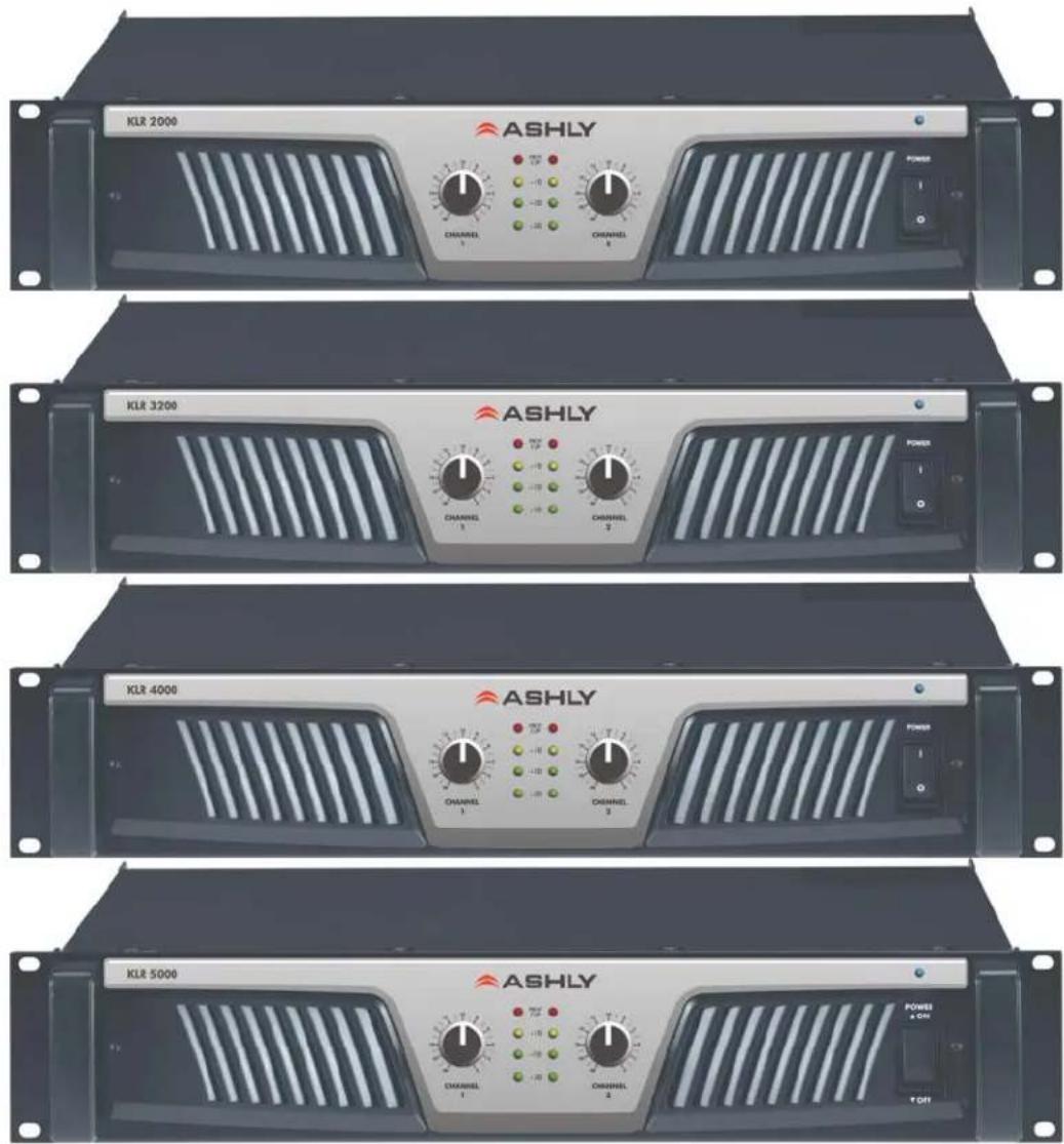
KLR 2000 ASHLY CHANNEL 1 CHANNEL 2 POWER I KLR 3200 ASHLY CHANNEL 1 CHANNEL 2 POWER I KLR 4000 ASHLY CHANNEL 1 CHANNEL 2 POWER I KLR 5000 ASHLY CHANNEL 1 CHANNEL 2 POWER & OFF T OFFAshly Audio Inc.
847 Holt Road, Webster, NY 14580-9103
Toll Free (800) 828-6308, Telephone (585) 872-0010, FAX (585) 872-0739
www.ashly.com
All Trademarks referred to herein, are the property of their respective owners.
All Rights Reserved r0515
Important Safety Instructions - 2
Introduction - 3
The KLR Series - 4
Physical Description - 5
Installation - 6
Troubleshooting - 10
Spec Table - 11
Warranty - 12
This manual uses a Perpetual Table Of Contents. Each page has a copy of the manual's contents in a gray box just like this one. The section you are in will always be bold with the other sections "grayed out." The feature allows you to jump directly to another section without having to return to a Table Of Contents page.
This power amplifier can produce dangerous output voltage, power and sound pressure levels. In order to minimize the risk of injury, damage, or hearing loss, please read the entire owner's manual.
The lightning flash with arrowhead symbol, within an equilateral triangle, is intended to alert the user to the presence of uninsulated "dangerous voltage" within the product's enclosure that may be of sufficient magnitude to constitute a risk of electric shock to persons. The exclamation point within an equilateral triangle is intended to alert the user to the presence of important operating and maintenance instructions in the literature accompanying the device.
- Read these instructions.
- Keep these instructions.
- Heed all warnings.
- Follow all instructions.
- To reduce the risk of fire or electric shock, do not expose this apparatus to rain or moisture.
- Do not use this apparatus near water.
- Clean only with dry cloth.
- Do not block any ventilation openings. Install in accordance with the manufacturer's instructions.
- Do not install near any heat sources such as radiators, heat registers, stoves, or other apparatus (including amplifiers) that produce heat.
- Do not defeat the safety purpose of the polarized or grounding-type plug. A polarized plug has two blades with one wider than the other. A grounding type plug has two blades and a third grounding prong. The wide blade or the third prong are provided for your safety. If the provided plug does not fit into your outlet, consult an electrician for replacement of the obsolete outlet.
- Protect the power cord from being walked on or pinched particularly at plugs, convenience receptacles, and the point where they exit from the apparatus.
- Only use attachments/accessories specified by the manufacturer.
- Use only with the cart, stand, tripod, bracket, or table specified by the manufacturer, or sold with the apparatus. When a cart is used, use caution when moving the cart/apparatus combination to avoid injury from tip-over.
- Unplug this apparatus during lightning storms or when unused for long periods of time.
- Refer all servicing to qualified service personnel. Servicing is required when the apparatus has been damaged in any way, such as power-supply cord or plug is damaged, liquid has been spilled or objects have fallen into the apparatus, the apparatus has been exposed to rain or moisture, does not operate normally, or has been dropped.
- To completely disconnect this apparatus from the AC mains, disconnect the power supply cord plug from the AC receptacle.
- The mains plug of the power supply cord shall remain readily accessible.
Congratulations on your purchase of an Ashly KLR-Series amplifier. The KLR-Series is made up of powerful, high-efficiency, lightweight amplifiers incorporating the latest technologies. We are confident that you will be pleased with the high performance, superb sound quality, reliability, and more.
About Ashly
Ashly Audio was founded in 1974 by a group of recording engineers, concert sound professionals, and electronics designers. The first products were elaborate custom consoles for friends and associates, but business quickly spread to new clients and the business grew. The philosophy we established from the very beginning holds true today: to offer only the highest quality audio tools at an affordable cost to the professional user – ensuring reliability and long life. More than thirty years later, Ashly remains committed to these principles.
FCC Compliance
This device complies with part 15 of the FCC Rules. Operation is subject to the following two conditions:
- This device may not cause harmful interference
- This device must accept any interference received, including interference that may cause undesired operation.
Note: This equipment has been tested and found to comply with the limits for a Class B digital device, pursuant to part 15 of the FCC Rules. These limits are designed to provide reasonable protection against harmful interference in both a commercial and residential installation. This equipment generates, uses and can radiate radio frequency energy and, if not installed and used in accordance with the instructions, may cause harmful interference to radio communications. However, there is no guarantee that interference will not occur in a particular installation. If this equipment does cause harmful interference to radio or television reception, which can be determined by turning the equipment off and on, the user is encouraged to try to correct the interference by one or more of the following measures:
- Reorient or relocate the receiving antenna.
- Increase the separation between the equipment and receiver.
- Connect the equipment into an outlet on a circuit different from that to which the receiver is connected.
- Consult the dealer or an experienced radio/TV technician for help.
Important Safety
Instructions - 2
Introduction - 3
About Ashly
FCC Compliance
The KLR Series - 4
Physical Description - 5
Installation - 6
Troubleshooting - 10
Spec Table - 11
Warranty - 12
Important Safety
Instructions - 2
Introduction - 3
The KLR Series - 4 Protection
Physical Description - 5
Installation - 6
Troubleshooting - 10
Spec Table - 11
Warranty - 12
The KLR Series
KLR-Series amplifiers are high-efficiency, lightweight high power amplifiers incorporating the latest amplifier technologies.
The series provides a power range of 1000 to 2500 watts per channel at 2 ohms (20Hz-20kHz, 1% THD). The KLR series is available in 2 channel versions at four power points. All models will drive 2, 4, or 8 ohm loads.
*The KLR 3200 can also be used as a two channel 70V distributed output amplifier providing up to 800W per channel. For 70V applications, Ashly recommends setting the amplifier's HiPass filter switch to 50Hz (see page 5).
| KLR-Series Power Ratings (per channel) | |||||
| Stereo | Mono | ||||
| Model | 70V | 8Ω | 4Ω | 2Ω | 4Ω |
| KLR 2000 X 350W | 600W | 1000W | 2000W | ||
| KLR 3200* | 800W | 650W | 1100W | 1600W | 3200W |
| KLR 4000 X 850W | 1400W | 2000W | 4000W | ||
| KLR 5000 | X | 1000W | 1700W | 2500W | 5000W |
- Inputs are via 3-pin Euroblock, XLR, and 14 " TRS connectors.
- Switch mode power supply provides high efficiency and low weight
• Output connectors are four pin Speakon type. - Rear panel switches include: Gain and Operation Mode, Limiter, and HPF.
- Forced air cooled (front panel intake, rear panel exhaust)
- Front panel indicators for output level, clip/protect, and power on/off
- Gain selectable switch for both channels
- Removable dust filters on front panel
- Rack ears for permanent installation in a standard 2RU 19"(rack mount width) enclosure
Protection
KLR-Series Amplifiers come standard with several protection circuits:
√ Output over-current protection
√ DC output protection
√ Chassis internal temperature monitoring
√ Inrush limiting
√ Mains circuit breaker (Mains fuse used in KLR-5000)
WARNING: Do not remove the mains connector ground.
Physical Description
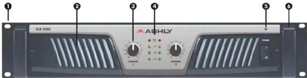
Each model in the KLR-Series is 2RU. The model number is indicated on the left side of the front panel
Amplifier Front Panel
text_image
1 2 3 4 5 6 ASHLY KLR 2000 CHANNELS 1 CHANNELS 2 HOLD I O- Mounting Holes – For rack mounting.
- Air Inflow Vents – Cool air enters here.
- Channel Attenuators - These knobs adjust the attenuation of the input signal of each channel from to 0.
-
Signal, Clip, and Protect LEDs – Indicates output level of -30, -20, -10dB, Clip, and amplifier protect.
-
Power Switch and LED – Switches the unit on or off. The KLR 2000, KLR 3200, and KLR 4000 use a switch with a built in mains circuit-breaker. The KLR 5000 uses a non-breaker switch and an internal mains fuse instead.
- Rack Handles – Handles on newer models can be removed using a 3mm hex wrench.
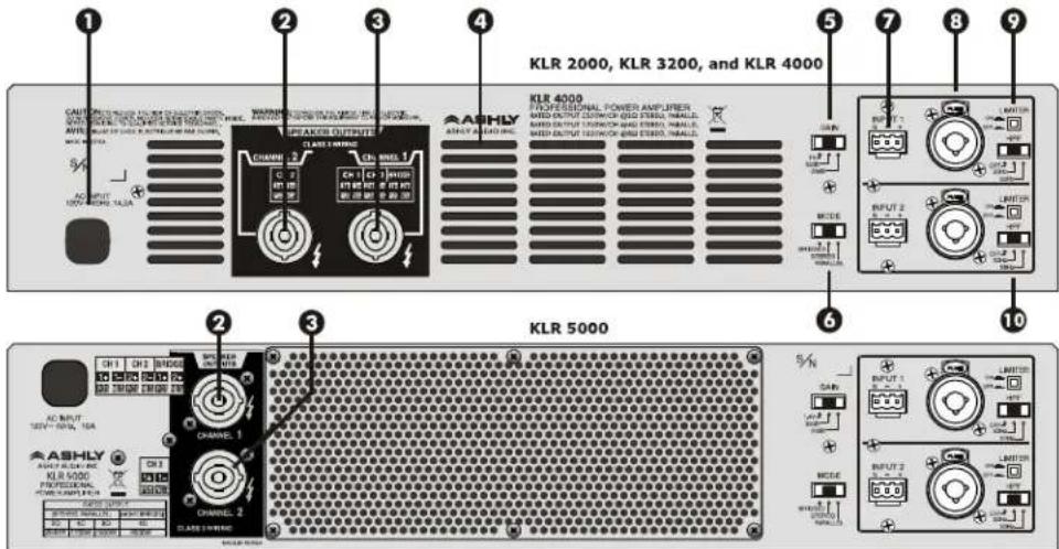
Amplifier Rear Panel (Note: KLR 5000 rear panel has different feature locations)
text_image
1 2 3 4 5 6 7 8 9 KLR 2000, KLR 3200, and KLR 4000 KLR 4000 POWER AMPLIFIER MID OUTPUT COCONIC QSO STRES, SMALL, MID OUTPUT SQUINIC AND STRES, SMALL, MID OUTPUT SQUINIC AND STRES, SMALL. KLR 5000 KLR 5000 KLM 2 CHANNEL 2 CHANNEL 1 CHANNEL 2 CHANNEL 1 CHANNEL 2 CHANNEL 1 CHANNEL 2 CHANNEL 1 CHANNEL 2 CHANNEL 1 CHANNEL 2 CHANNEL 1 CHANNEL 2 CHANNEL 1 CHANNEL 2 CHANNEL 1 CHANNEL 2 CHANNEL 1 CHANNEL 2 CHANNEL 1 CHANNEL 2 CHANNEL 1 CHANNEL 2 CHANNEL 1 CHANNEL 2 CHANNEL 1 CHANNEL 1 CHANNEL 2 CHANNEL 1 CHANNEL 2 CHANNEL 1 CHANNEL 2 CHANNEL 1 CHANNEL 2 CHANNEL 1 CHANNEL 2 CHANNEL 1 CHANNEL 2 CHANNEL 1 CHANNEL 2 CHANNEL 1 CHANNEL 2 CHANNEL 1 CHANNEL 2 CHANNEL 1 CHANNEL 2 CHANNEL 1 CHANNEL 2 CHANNEL 1 CHANNEL 2 CHANNEL 2 CHANNEL 1 CHANNEL 2 CHANNEL 1 CHANNEL 2 CHANNEL 1 CHANNEL 2 CHANNEL 1 CHANNEL 2 CHANNEL 1 CHANNEL 2 CHANNEL 1 CHANNEL 2 CHANNEL 1 CHANNEL 2 CHANNEL 1 CHANNEL 2 CHANNEL 1 CHANNEL 2 CHANNEL 1 CHANNEL 2 CHANNEL 1 CHANNEL 2 CHANNEL 1 channel control panel (SIP) channel control panel (SIP) channel control panel (SIP) channel control panel (SIP) channel control panel (SIP) channel control panel (SIP) channel control panel (SIP) channel control panel (SIP) channel control panel (SIP) channel control panel (SIP) channel control panel (SIP) channel control panel (SIP) channel control panel (SIP) channel control panel (SIP) channel control panel (SIP) channel controller (SIP) channel controller (SIP) channel controller (SIP) channel controller (SIP) channel controller (SIP) channel controller (SIP) channel controller (SIP) channel controller (SIP) channel controller (SIP) channel controller (SIP) channel controller (SIP) channel controller (SIP) channel controller (SIP) channel controller (SIP) channel controller (SIP) channel controller (SIP) channel controller (SIP)- AC Cord – For connection to the AC mains
- CH 1, CH 2, Bridged Output Connector – This connector provides the amplifier's Channel 1, channel 1 and 2, or bridged output.
- CH 2 Output Connector – This connector provides the amplifier's Channel 2 output.
- Air Outflow Vents – Warm air exits here.
- Gain Switch – The Gain switch sets the gain for both channels. Gain selections vary between models. Check specifications for each model.
-
Mode Switch – This switch selects the amplifier's operating mode (Bridge, Stereo, or Parallel Mono).
-
3-Pin Euroblock Input Connectors – These connectors are used for balanced or unbalanced input signals. For parallel mode or bridged mode, use INPUT 1 only.
- Combination XLR, 1/4" TRS Input Connectors – These connectors are used for balanced or unbalanced input signals, and are wired in parallel with the Euroblock connector.
- Limiter Switch – This switch engages the limiter. There is a separate limiter for each channel.
- HPF Switch – This switch selects the input HiPass filter to 30Hz, 50Hz, or Off.
Important Safety
Instructions-2
Introduction - 3
The KLR Series - 4
Physical Description - 5
Front Panel
Rear Panel
Installation - 6
Troubleshooting - 10
Spec Table - 11
Warranty - 12
Important Safety
Instructions - 2
Introduction - 3
The KLR Series - 4
Physical Description - 5
Front Panel
Rear Panel
Installation - 6
Requirements
Installation Density
Typical Applications
Connectors & Polarity
Speaker Connections
Troubleshooting - 10
Spec Table - 11
Warranty - 12
Installation
KLR-Series amplifiers are designed for use in both fixed and mobile sound systems. Each amplifier is shipped (unless otherwise specified) with the following factory settings:
| Front panel: Rear panel: | |
| On/Off Switch = OffAttenuators =∞ | High Pass Filter(s) = OffGain Selector = Max Gain PositionMode Selector = StereoLimiter Switch = Off |
Before connecting to mains power, make sure that the switches are set to the configuration needed for your particular application. Always switch the amplifier off before making any changes to the settings. Failure to do so could result in damage to the unit or other components in your system. CAUTION: When mounting or connecting the amplifier, always disconnect it from the mains. Use four screws and washers when mounting the amplifier to the front rack rails. Rear support is also recommended, especially for mobile or touring use. To reduce the risk of fire or electric shock, do not expose this apparatus to rain or moisture.
Requirements
KLR-Series amplifiers have specific physical, electrical and signal requirements for proper operation. These requirements will vary depending on your specific application, setup, and the settings on the amplifier. When setting up and testing your system, please take special care to double check all connections and settings. Please refer to the specifications section of this manual for specific input, output and other figures.
Installation Density
KLR-Series amplifiers produce substantial power output from a small chassis. When driven at the higher-end of their potential, they do produce heat that must be dissipated. In cases where multiple KLR amplifiers are mounted together (or a single KLR with other equipment), it is recommended that a 1RU space is left between units to allow for proper air circulation. If the amplifier overheats, it will go into ‘thermal’ protect mode to prevent damage to itself and any connected components and speakers.
text_image
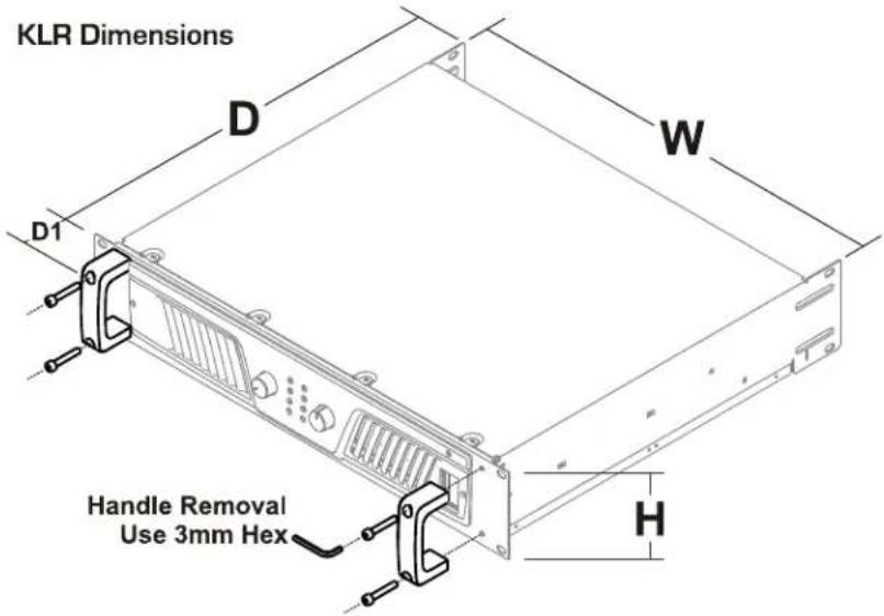
KLR Dimensions D W D1 Handle Removal Use 3mm Hex H| H = 3.47" (88.1mm) |
| W = 17.6" (447mm) |
| D = 16.0" (406mm) |
| D1 = 1.5" (38.1mm) |
Typical Applications (Note: KLR 5000 not shown - see page 5)
text_image
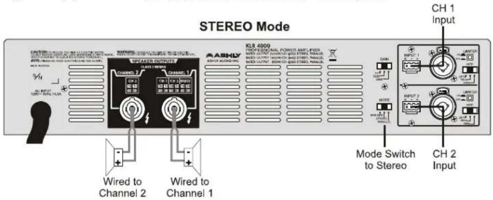
STEREO Mode WIREND SPEAKER OUTPUTS CLASS 1 MANGE CHAVER 2 CHAVER 1 CHA 2 CHA 3 CHA 4 CHA 5 CHA 6 CHA 7 CHA 8 CHA 9 CHA 10 CHA 11 CHA 12 CHA 13 CHA 14 CHA 15 CHA 16 CHA 17 CHA 18 CHA 19 CHA 20 CHA 21 CHA 22 CHA 23 CHA 24 CHA 25 CHA 26 CHA 27 CHA 28 CHA 29 CHA 30 CHA 31 CHA 32 CHA 33 CHA 34 CHA 35 CHA 36 CHA 37 CHA 38 CHA 39 CHA 40 CHA 41 CHA 42 CHA 43 CHA 44 CHA 45 CHA 46 CHA 47 CHA 48 CHA 49 CHA 50 CHA 51 CHA 52 CHA 53 CHA 54 CHA 55 CHA 56 CHA 57 CHA 58 CHA 59 CHA 60 CHA 61 CHA 62 CHA 63 CHA 64 CHA 65 CHA 66 CHA 67 CHA 68 CHA 69 CHA 70 CHA 71 CHA 72 CHA 73 CHA 74 CHA 75 CHA 76 CHA 77 CHA 78 CHA 79 CHA 80 CHA 81 CHA 82 CHA 83 CHA 84 CHA 85 CHA 86 CHA 87 CHA 88 CHA 89 CHA 90 CHA 91 CHA 92 CHA 93 CHA 94 CHA 95 CHA 96 CHA 97 CHA 98 CHA 99 CHA 100 MODE SWITCH to Stereo CH 1 InputThe most common use of a KLR-Series amplifier is a 2-channel source driving 2 speaker channels. In this illustration, the amplifier is receiving a stereo signal and is driving two stereo speakers. The amplifier is in STEREO mode.
text_image
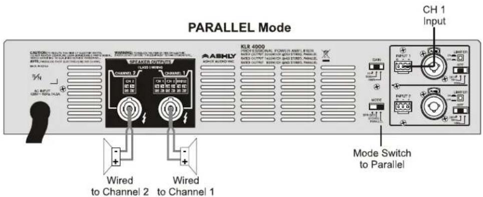
PARALLEL Mode CAUTIONS SELECT ON MODE 1 (AVERAGE MODE) ON MODE 1 (AVERAGE MODE) OR OFF COLDING (RANGE, WIDTH, POWER, etc.) OFF COLDING (RANGE, WIDTH, POWER, etc.) AMOUNTING ON MODE 2 (RANGE, WIDTH, POWER, etc.) AMOUNTING ON MODE 3 (RANGE, WIDTH, POWER, etc.) AMOUNTING ON MODE 4 (RANGE, WIDTH, POWER, etc.) AMOUNTING ON MODE 5 (RANGE, WIDTH, POWER, etc.) AMOUNTING ON MODE 6 (RANGE, WIDTH, POWER, etc.) AMOUNTING ON MODE 7 (RANGE, WIDTH, POWER, etc.) AMOUNTING ON MODE 8 (RANGE, WIDTH, POWER, etc.) AMOUNTING ON MODE 9 (RANGE, WIDTH, POWER, etc.) AMOUNTING ON MODE 10 (RANGE, WIDTH, POWER, etc.) AMOUNTING ON MODE 11 (RANGE, WIDTH, POWER, etc.) AMOUNTING ON MODE 12 (RANGE, WIDTH, POWER, etc.) AMOUNTING ON MODE 13 (RANGE, WIDTH, POWER, etc.) AMOUNTING ON MODE 14 (RANGE, WIDTH, POWER, etc.) AMOUNTING ON MODE 15 (RANGE, WIDTH, POWER, etc.) AMOUNTING ON MODE 16 (RANGE, WIDTH, POWER, etc.) AMOUNTING ON MODE 17 (RANGE, WIDTH, POWER, etc.) AMOUNTING ON MODE 18 (RANGE, WIDTH, POWER, etc.) AMOUNTING ON MODE 19 (RANGE, WIDTH, POWER, etc.) AMOUNTING ON MODE 20 (RANGE, WIDTH, POWER, etc.) AMOUNTING ON MODE 21 (RANGE, WIDTH, POWER, etc.) AMOUNTING ON MODE 22 (RANGE, WIDTH, POWER, etc.) AMOUNTING ON MODE 23 (RANGE, WIDTH, POWER, etc.) AMOUNTING ON MODE 24 (RANGE, WIDTH, POWER, etc.) AMOUNTING ON MODE 25 (RANGE, WIDTH, POWER, etc.) AMOUNTING ON MODE 26 (RANGE, WIDTH, POWER, etc.) AMOUNTING ON MODE 27 (RANGE, WIDTH, POWER, etc.) AMOUNTING ON MODE 28 (RANGE, WIDTH, POWER, etc.) AMOUNTING ON MODE 29 (RANGE, WIDTH, POWER, etc.) AMOUNTING ON MODE 30 (RANGE, WIDTH, POWER, etc.) AMOUNTING ON MODE 31 (RANGE, WIDTH, POWER, etc.) AMOUNTING ON MODE 32 (RANGE, WIDTH, POWER, etc.) AMOUNTING ON MODE 33 (RANGE, WIDTH, POWER, etc.) AMOUNTING ON MODE 34 (RANGE, WIDTH, POWER, etc.) AMOUNTING ON MODE 35 (RANGE, WIDTH, POWER, etc.) AMOUNTING ON MODE 36 (RANGE, WIDTH, POWER, etc.) AMOUNTING ON MODE 37 (RANGE, WIDTH, POWER, etc.) AMOUNTING ON MODE 38 (RANGE, WIDTH, POWER, etc.) AMOUNTING ON MODE 39 (RANGE, WIDTH, POWER, etc.) AMOUNTING ON MODE 40 (RANGE, WIDTH, POWER, etc.) AMOUNTING ON MODE 41 (RANGE, WIDTH, POWER, etc.) AMOUNTING ON MODE 42 (RANGE, WIDTH, POWER, etc.) AMOUNTING ON MODE 43 (RANGE, WIDTH, POWER, etc.) AMOUNTING ON MODE 44 (RANGE, WIDTH, POWER, etc.) AMOUNTING ON MODE 45 (RANGE, WIDTH, POWER, etc.) AMOUNTING ON MODE 46 (RANGE, WIDTH, POWER, etc.) AMOUNTING ON MODE 47 (RANGE, WIDTH, POWER, etc.) AMOUNTING ON MODE 48 (RANGE, WIDTH, POWER, etc.) AMOUNTING ON MODE 49 (RANGE, WIDTH, POWER, etc.) AMOUNTING ON MODE 50 (RANGE, WIDTH, POWER, etc.) AMOUNTING ON MODE 51 (RANGE, WIDTH, POWER, etc.) AMOUNTING ON MODE 52 (RANGE, WIDTH, POWER, etc.) AMOUNTING ON MODE 53 (RANGE, WIDTH, POWER, etc.) AMOUNTING ON MODE 54 (RANGE, WIDTH, POWER, etc.) AMOUNTING ON MODE 55 (RANGE, WIDTH, POWER, etc.) AMOUNTING ON MODE 56 (RANGE, WIDTH, POWER, etc.) AMOUNTING ON MODE 57 (RANGE, WIDTH, POWER, etc.) AMOUNTING ON MODE 58 (RANGE, WIDTH, POWER, etc.) AMOUNTING ON MODE 59 (RANGE, WIDTH, POWER, etc.) AMOUNTING ON MODE 60 (RANGE, WIDTH, POWER, etc.) AMOUNTING ON MODE 61 (RANGE, WIDTH, POWER, etc.) AMOUNTING ON MODE 62 (RANGE, WIDTH, POWER, etc.) AMOUNTING ON MODE 63 (RANGE, WIDTH, POWER, etc.) AMOUNTING ON MODE 64 (RANGE, WIDTH, POWER, etc.) AMOUNTING ON MODE 65 (RANGE, WIDTH, POWER, etc.) AMOUNTING ON MODE 66 (RANGE, WIDTH, POWER, etc.) AMOUNTING ON MODE 67 (RANGE, WIDTH, POWER, etc.) AMOUNTING ON MODE 68 (RANGE, WIDTH, POWER, etc.) AMOUNTING ON MODE 69 (RANGE, WIDTH, POWER, etc.) AMOUNTING ON MODE 70 (RANGE, WIDTH, POWER, etc.) AMOUNTING ON MODE 71 (RANGE, WIDTH, POWER, etc.) AMOUNTING ON MODE 72 (RANGE, WIDTH, POWER, etc.) AMOUNTING ON MODE 73 (RANGE, WIDTH, POWER, etc.) AMOUNTING ON MODE 74 (RANGE, WIDTH, POWER, etc.) AMOUNTING ON MODE 75 (RANGE, WIDTH, POWER, etc.) AMOUNTING ON MODE 76 (RANGE, WIDTH, POWER, etc.) AMOUNTING ON MODE 77 (RANGE, WIDTH, POWER, etc.) AMOUNTING ON MODE 78 (RANGE, WIDTH, POWER, etc.) AMOUNTING ON MODE 79 (RANGE, WIDTH, POWER, etc.) AMOUNTING ON MODE 80 (RANGE.Another use of a KLR-Series amplifier is a single channel source driving both speaker channels. In this illustration, the amplifier is receiving a signal and is driving both channel speakers with the same signal. The amplifier is in PARALLEL mode.
text_image
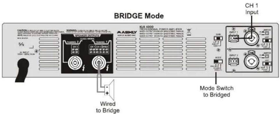
BRIDGE Mode CAUTIONAL SWITCH ON CH1 INPUT (A) OF CH2 INPUT (B) OF CH3 INPUT (C) OF CH4 INPUT (D) OF CH5 INPUT (E) OF CH6 INPUT (F) OF CH7 INPUT (G) OF CH8 INPUT (H) OF CH9 INPUT (I) OF CH10 INPUT (J) OF CH11 INPUT (K) OF CH12 INPUT (L) OF CH13 INPUT (M) OF CH14 INPUT (N) OF CH15 INPUT (O) OF CH16 INPUT (P) OF CH17 INPUT (Q) OF CH18 INPUT (R) OF CH19 INPUT (S) OF CH20 INPUT (T) OF CH21 INPUT (U) OF CH22 INPUT (V) OF CH23 INPUT (W) OF CH24 INPUT (X) OF CH25 INPUT (Y) OF CH26 INPUT (Z) OF CH27 INPUT (A) OF CH28 INPUT (A) OF CH29 INPUT (A) OF CH30 INPUT (A) OF CH31 INPUT (A) WARNING: 1.00% 0.00% 0.00% 0.00% 0.00% 0.00% 0.00% 0.00% 0.00% 0.00% 0.00% 0.00% 0.00% 0.00% 0.00% 0.00% 0.00% 0.00% SPEAKER OUTPUTS CLASS 2 MINDING ASHLY AUDIO INC KL8 4990 VECH FEEDUNAL POWER AMPLIER MATH OUTPUT 250V/CH-250D STWD. PANEL MATH OUTPUT 450V/CH-450D STWD. PANEL MATH OUTPUT 450V/CH-450D STWD. PANEL Mode Switch to Bridged CAN INPUT 1 LIMITED RUNUT 2 UNITED RUNUT 3 RUNUT 4 RUNUT 5 RUNUT 6 RUNUT 7 RUNUT 8 RUNUT 9 RUNUT 10 RUNUT 11 RUNUT 12 RUNUT 13 RUNUT 14 RUNUT 15 RUNUT 16 RUNUT 17 RUNUT 18 RUNUT 19 RUNUT 20 RUNUT 21 RUNUT 22 RUNUT 23 RUNUT 24 RUNUT 25 RUNUT 26 RUNUT 27 RUNUT 28 RUNUT 29 RUNUT 30 RUNUT 31 RUNUT 32 RUNUT 33 RUNUT 34 RUNUT 35 RUNUT 36 RUNUT 37 RUNUT 38 RUNUT 39 RUNUT 40 RUNUT 41 RUNUT 42 RUNUT 43 RUNUT 44 RUNUT 45 RUNUT 46 RUNUT 47 RUNUT 48 RUNUT 49 RUNUT 50 RUNUT 51 RUNUT 52 RUNUT 53 RUNUT 54 RUNUT 55 RUNUT 56 RUNUT 57 RUNUT 58 RUNUT 59 RUNUT 60 RUNUT 61 RUNUT 62 RUNUT 63 RUNUT 64 RUNUT 65 RUNUT 66 RUNUT 67 RUNUT 68 RUNUT 69 RUNUT 70 RUNUT 71 RUNUT 72 RUNUT 73 RUNUT 74 RUNUT 75 RUNUT 76 RUNUT 77 RUNUT 78 RUNUT 79 RUNUT 80 RUNUT 81 RUNUT 82 RUNUT 83 RUNUT 84 RUNUT 85 RUNUT 86 RUNUT 87 RUNUT 88 RUNUT 89 RUNUT 90 RUNUT 91 RUNUT 92 RUNUT 93 RUNUT 94 RUNUT 95 RUNUT 96 RUNUT 97 RUNUT 98 RUNUT 99 RUNUT 100KLR-Series amplifiers are well suited to BRIDGED operation to drive a speaker load such as a subwoofer. This illustration shows a KLR driving a signal in BRIDGED mode. Note the special wiring to the channel 1 connector for Bridge mode. Minimum Bridged load impedance is 4 (2Ω per channel).
Important Safety
Instructions - 2
Introduction - 3
The KLR Series - 4
Physical Description - 5
Installation - 6
Requirements
Installation Density
Typical Applications
Connectors & Polarity
Speaker Connections
Troubleshooting - 10
Spec Table - 11
Warranty - 12
Important Safety
Instructions - 2
Introduction - 3
The KLR Series - 4
Physical Description - 5
Installation - 6
Requirements
Installation Density
Typical Applications
Connectors & Polarity
Speaker Connections
Troubleshooting - 10
Spec Table - 11
Warranty - 12
Connectors & Polarity
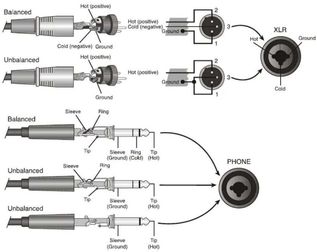
KLR-Series amplifiers utilize three types of professional audio connectors. For the inputs, 3-pin Euroblock connectors are utilized with their polarity clearly marked on the amplifier's rear panel, and combination XLR and 1/4" phone jack are all wired in parallel. Outputs are four pin Speakon type connectors. The polarity for these connections is marked on the unit's chassis. Note that polarity changes when the unit is operated in BRIDGED mode. Be sure to read the Operation section of this manual for important information on the operating modes.
flowchart
graph TD
    A["Balanced"] --> B["Hot (positive)"]
    B --> C["Cold (negative)"]
    C --> D["Ground"]
    E["Unbalanced"] --> F["Hot (positive)"]
    F --> G["Cold (negative)"]
    G --> H["Ground"]
    I["Sleeve"] --> J["Ring"]
    K["Sleeve (Ground)"] --> L["Ring (Cold)"]
    M["Sleeve (Ground)"] --> N["Tip (Hot)"]
    O["Sleeve (Ground)"] --> P["Tip (Hot)"]
    Q["Ground"] --> R["2 3 1"]
    S["XLR"] --> T["Hot"]
    U["Phone"] --> V["2 3 1"]
    W["Ground"] --> X["2 3 1"]
    Y["Ground"] --> Z["2 3 1"]
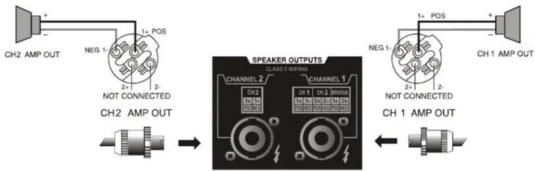
Speaker Connections [Note: KLR 5000 speaker outputs not shown - see page 5]
flowchart
graph LR
    A["CH2 AMP OUT"] -->|1+ POS| B["Speaker Outputs"]
    C["CH2 AMP OUT"] --> D["Speaker Outputs"]
    E["CH1 AMP OUT"] --> F["Speaker Outputs"]
    style A fill:#f9f,stroke:#333
    style C fill:#f9f,stroke:#333
    style E fill:#f9f,stroke:#333
    style B fill:#ccf,stroke:#333
    style D fill:#ccf,stroke:#333
    style F fill:#ccf,stroke:#333
Stereo Speaker Wiring
In this mode, the amplifier's channels operate fully independent of each other. Each signal enters the unit and is amplified separately and wired using different connectors.
text_image
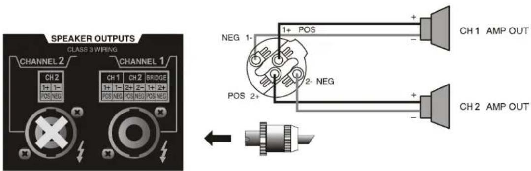
SPEAKER OUTPUTS CLASS 3 WIRING CHANNEL 2 CHANNEL 1 CH2 1+ 1- POS NEG CH1 CH2 BRIDGE 1+ 1- 2+ 2- 1+ 2+ POS NEG POS NEG POS NEG NEG 1- POS 1+ POS 2- NEG POS 2+ CH1 AMP OUT CH2 AMP OUTStereo Speaker Wiring Using Single 4-Conductor Speaker Cable
In this mode, the amplifier's channels still operate independent of each other. Each signal is amplified separately, however both channels are wired using the Channel 1 connector.
text_image
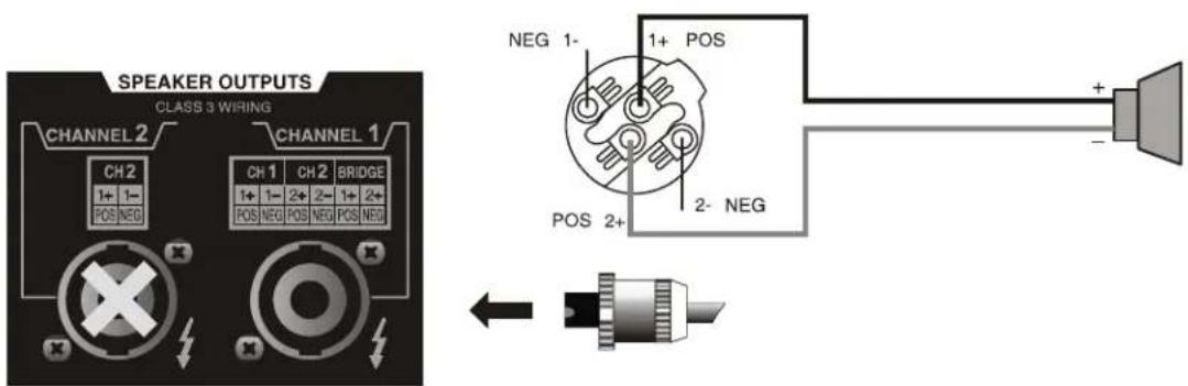
SPEAKER OUTPUTS CLASS 3 WIRING CHANNEL 2 CHANNEL 1 CH 2 1+ 1- POS NEG CH 1 1+ 1- POS NEG CH 2 BRIDGE 2- 1+ POS NEG POS NEG NEG 1- POS 2+ 1+ POS 2- NEG POS 2+ + - ←Bridged (Mono) Mode
In this mode, a single input is connected to channel 1 and is connected to the two output channels that have been “Bridged” together using the Channel 1 connector. Minimum Bridged load impedance is 4 .
Important Safety
Instructions - 2
Introduction - 3
The KLR Series - 4
Physical Description - 5
Installation - 6
Requirements
Installation Density
Typical Applications
Connectors & Polarity
Speaker Connections
Troubleshooting - 10
Spec Table - 11
Warranty - 12
Important Safety
Instructions - 2
Introduction - 3
The KLR Sries - 4
Physical Description - 5
Installation-6
Troubleshooting - 10
Spec Table - 11
Warranty - 12
Troubleshooting
| Situation Indication Action | ||
| No Sound | Signal LED not litClip LEDs not lit | Check AC plug. Confirm that AC outlet works by plugging in another device. |
| Signal LED not lit Make sure the signal source is operating and try another cable. Check position of Volume Pots. | ||
| Signal LEDs responding to signal level Check the speaker wiring for breaks.Try another speaker and cable. | ||
| Protect LED is lit Overheating will cause protective muting.Check for proper ventilation. | ||
| No Channel Separation | No Channel Separation Check the mode indicators on the back paneland make sure the mode selector on the rear panel is in the stereo position. Make sure other equipment in the signal path such as mixers and preamps are set for stereo, not mono | |
| Distorted Sound | Power LED is lit A faulty speaker or a loose connection could cause this. Check the wiring and try another speaker. | |
| Signal LEDs responding to signal level | The signal source might be clipping. Keep the volume pots at least halfway up so that the source does not have to be overdriven. | |
| Clip LEDs not lit Keep the volume pots at least halfway up and try changing input sensitivity with the gain selector on the rear. | ||
| Hiss Hiss Unplug the amplifier input to confirm that the | hiss is coming from the source or from a device upstream. Erratic or popping noises indicate an electronic fault in the offending unit. To keep the noise floor low, operate the primary signal source at full level, without clipping. Avoid boosting the signal further between the source and the amplifier. | |
| Squeals and Feedback | Squeals and Feedback Microphone feedback should be eliminated with mixer controls. If noise continues to build up with no microphone gain, there is a serious fault in the signal processors or cables.Working in succession from the signal source towards the amplifier and check each device in the signal path by reducing its gain or by unplugging it. | |
Specification Table
| KLR 2000 | KLR 3200 | KLR 4000 | KLR 5000 | |
| Power Output Per Channel | ||||
| Stereo Mode, both channels driven | ||||
| 8Ω, 20Hz - 20kHz, 1% THD | 350W | 650W | 850W | 1000W |
| 4Ω, 20Hz - 20kHz, 1% THD | 600W | 1100W | 1400W | 1700W |
| 2Ω, 20Hz - 20kHz, 1% THD | 1000W | 1600W | 2000W | 2500W |
| 70V Output, 20Hz - 20kHz, 1% THD, per channel | X | 800W | X | X |
| Bridged Mono Mode | ||||
| 4Ω, 20 Hz - 20 kHz, 1% THD | 2000W | 3200W | 4000W | 5000W |
| Line Current Draw* (all channels driven @4Ω) | ||||
| Idle (120VAC 60Hz) * | 0.99A | 0.92A | 1.05A | 1.14A |
| 1/8th Power Pink Noise (120VAC 60Hz) * | 9.7A | 11.4A | 14.0A | 17.5A |
| 1/3 Power Sine Wave (120VAC 60Hz) * | 14.9A | 16.6A | 19.8A | 24.7A |
| Thermal Dissipation (all channels driven @4Ω) | ||||
| Idle (BTU/hr) | 164 | 136 | 171 | 215 |
| 1/8th Power Pink Noise (BTU/hr) | 1876 | 2063 | 2489 | 3111 |
| 1/3 Power Sine Wave (BTU/hr) | 2880 | 3001 | 3516 | 4395 |
| Input Gain Switch | 1V, 26dB, 20dB | 1V, 32dB, 26dB | 1V, 32dB, 26dB | 1.4V, 32B, 26dB |
| Signal to Noise Ratio(20Hz-20kHz, rated power @ 8Ω unweighted) | >108 dB | >109 dB | >109 dB | >110 dB |
| Output Circuitry: | Class AB | 2 Step Class H | 2 Step Class H | 2 Step Class H |
| Frequency Response 1W @ 8Ω 20Hz-20kHz(-3dB down point) | +/- 0.3dB5Hz - 70kHz | |||
| Damping Factor - 100Hz @ rated power @8Ω | >380 | |||
| THD 20Hz-20kHz, 10dB below rated output @4Ω | <0.05% | |||
| Input Impedance | 12 kΩ, balanced | |||
| HPF (30Hz, 50Hz, Off) | 12dB/Oct | |||
| Amplifier Protection | Output Overcurrent, DC Output, Chassis Temperature, Mains Breaker(KLR-5000 uses Internal Mains Fuse Instead of Breaker) | |||
| Cooling | Variable Speed Fan, Front to Rear Air Flow | |||
| Front Panel Indicators | Prot/Clip, Signal, Power | |||
| Attenuators | Per channel: front panel | |||
| Input Connectors, each channel | 3-Pin Euroblock, XLR, 1⁄4" TRS Phone Jack | |||
| Output connectors, each channel | Four pin Speakon type | |||
| Operating Temperature/Humidity | Temperature: -10C - +40C / Humidity: 0% - 90% | |||
| Power Cable Connector | 3-Prong NEMA 5-15 (5-20 for KLR-5000) | |||
| Dimensions | 19" x 3.5" x 16" (482mm x 88mmx x407mm) | |||
| Weight | 24 lbs (10.9kg) | 26.4 lbs (12kg) | 26.7 lbs (12.1kg) | 28.2 lbs (12.8kg) |
* For 230VAC 50Hz models, divide Line Current Draw values by 2.
All Specifications Subject to Change or Improvement Without Notice.
Important Safety
Instructions - 2
Introduction - 3
The KLR Series - 4
Physical Description - 5
Installation - 6
Troubleshooting - 10
Spec Table - 11
Warranty - 12
Important Safety
Instructions - 2
Introduction - 3
The KLR Series - 4
Physical Description - 5
Installation - 6
Troubleshooting - 10
Spec Table - 11
Warranty - 12
Ashly Audio Inc. LIMITED WARRANTY (USA ONLY)
(Other countries please contact your respective distributor or dealer.)
For units purchased in the USA, warranty service for this unit shall be provided by ASHLY AUDIO, INC. in accordance with the following warranty statement.
ASHLY AUDIO, INC. warrants to the owner of this product that it will be free from defects in workmanship and materials for a period of FIVE years from the original-date-of-purchase. ASHLY AUDIO INC. will without charge, repair or replace at its discretion, any defective product or component parts upon prepaid delivery of the product to the ASHLY AUDIO, INC. factory service department, accompanied with a proof of original-date-of-purchase in the form of a valid sales receipt. This warranty gives you specific legal rights, and you may also have other rights, which vary from state to state.
EXCLUSIONS: This warranty does not apply in the event of misuse, neglect, or as a result of unauthorized alterations or repairs made to the product. This warranty is void if the serial number is altered, defaced, or removed. ASHLY AUDIO, INC. reserves the right to make changes in design, or make additions to, or improvements upon, this product without any obligation to install the same on products previously manufactured.
Any implied warranties, which may arise under the operation of state law, shall be effective only for FIVE years from the original-date-of-purchase of the product. ASHLY AUDIO, INC. shall be obligated to only correct defects in the product itself. ASHLY AUDIO, INC. is not liable for any damage or injury, which may result from, or be incidental to, or a consequence of, such defects. Some states do not allow limitations on how long an implied warranty lasts, or the exclusion, or limitation of incidental or consequential damages, so the above limitations or exclusions may not apply to you.
OBTAINING WARRANTY SERVICE:
For warranty service in the United States, please follow this procedure:
1) Return the product to ASHLY AUDIO, INC. freight prepaid, with a written statement describing the defect and application that the product is used in. ASHLY AUDIO, INC. will examine the product and perform any necessary service, including replacement of defective parts, at no further cost to you.
2) Ship your product to:
ASHLY AUDIO, INC.
Attention: Service Department
847 Holt Road
Webster, NY 14580-9103