
TM-360 - Receiver Ashly - Free user manual and instructions
Find the device manual for free TM-360 Ashly in PDF.


| Product Type | Audio/Video Receiver |
| Brand | Ashly |
| Model | TM-360 |
| Dimensions (W x H x D) | 17 in x 3.5 in x 12 in (43.2 cm x 8.9 cm x 30.5 cm) |
| Weight | 10.5 lbs (4.8 kg) |
| Power Consumption | 100 W (idle), 400 W (max) |
| Power Supply | AC 120V/60Hz or 230V/50Hz (switchable) |
| Frequency Response | 20 Hz - 20 kHz ±0.5 dB |
| Total Harmonic Distortion (THD) | <0.05% |
| Signal-to-Noise Ratio | >100 dB |
| Inputs | 6 x RCA, 2 x XLR, 2 x Optical, 1 x Coaxial |
| Outputs | 2 x Speaker (binding posts), 1 x Pre-out, 1 x Headphone (1/4") |
| Tuner Bands | AM, FM |
| Preset Stations | 30 AM, 30 FM |
| Remote Control | Infrared (included) |
| Integrated Amplifier Power | 100 W per channel (8 ohms, 20 Hz - 20 kHz, 2 channels driven) |
| Supported Audio Formats | MP3, AAC, WMA, FLAC (via USB) |
| USB Port | 1 x Type-A (front) |
| Bluetooth | Version 4.2, A2DP, AVRCP |
| Operating Temperature | 32°F - 104°F (0°C - 40°C) |
| Cleaning Instructions | Wipe with dry cloth; avoid solvents |
| Safety Features | Overload protection, thermal shutdown, short circuit protection |
| Spare Parts Availability | Contact Ashly support for replacement parts |
| Repair Service | Authorized service centers; user-replaceable fuse |
Frequently Asked Questions - TM-360 Ashly
User questions about TM-360 Ashly
0 question about this device. Answer the ones you know or ask your own.
Ask a new question about this device
Download the instructions for your Receiver in PDF format for free! Find your manual TM-360 - Ashly and take your electronic device back in hand. On this page are published all the documents necessary for the use of your device. TM-360 by Ashly.
USER MANUAL TM-360 Ashly
Public Address Amplifier
Operating Manual
The lightning flash with arrowhead symbol, within an equilateral triangle, is intended to alert the user to the presence of uninsulated "dangerous voltage" within the product's enclosure that may be of sufficient magnitude to constitute a risk of electric shock to persons. The exclamation point within an equilateral triangle is intended to alert the user to the presence of important operating and maintenance instructions in the literature accompanying the device.
This device complies with part 15 of the FCC Rules. Operation is subject to the following two conditions:
- This device may not cause harmful interference
- This device must accept any interference received, including interference that may cause undesired operation.
WARNING:
THIS APPARATUS MUST BE EARTHED
Table Of Contents
Safety Instructions 2
Front Panel Features 4
Rear Panel Features .... 5
Typical Application 8
Speaker Wiring....9
Dimensions 10
Schematic Block Diagram 11
Specifications 12
Limited Warranty....13
Overview
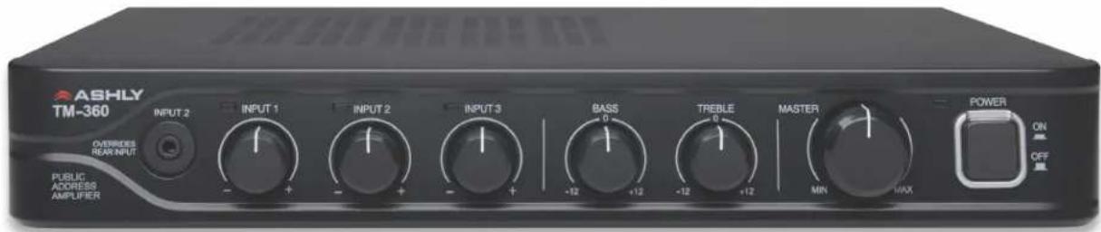
The Ashly TM-360 is a table-top mixer and 60W mono amplifier suitable for applications that require background music with priority paging from a single microphone. Features include:
- Mic/line input with switchable phantom power, plus two additional line level inputs
- LED signal present indicators on input channels
- Mic/line input can have priority over line input 2, input 2 can have priority over line input 3
- 60 watt speaker output with 4 , 70V, and 25V taps
- 230V export version has 60 watt speaker output with 4Ω, 70V, and 100V taps
- Second zone output with a 1W 8Ω output and a balanced 600Ω output
- Independent 600Ω PRE output
- Euroblock connectors on all inputs and outputs
- Line inputs also use summed mono dual RCA jacks
- Rear panel DIP switch for zone 2 assignment, input priority, mute link status, low cut filter, and phantom power
● Automatic sleep mode after 25 minutes of inactivity - Master standby mode using contact closure.
- Limited five year warranty
- Safety/Compliance: cCSAus, CE, FCC, RoHS
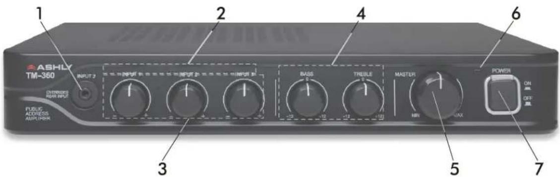
Front Panel Features
1) Input 2 Jack
This is a 3.5mm tip-ring-sleeve (TRS) jack on the front panel that drives input 2. This jack is very useful for connecting MP3 players, and overrides all input 2 connections on the back panel.
2) Input Signal LEDs (3)
These green LEDs flash when signal is present and the input level control is turned up. They only indicate signal present, not clipping. Also, if the TM-360 is in sleep mode from audio inactivity, at least one input signal LED must show signal activity for the amplifier to automatically wake up.
3) Input Level Controls (3)
These adjust the input signal levels sent to the master level control. Note that input signal LEDs indicate audio taken after the input level controls.
4) Bass and Treble Controls
These control the bass and treble of the main amplifier output.
5) Master Volume Control
This controls the main amplifier output level. There is a separate rear panel level control for zone 2 output.
6) Power LED
This LED is blue when the amplifier is powered on and active, and is red when in sleep or standby mode.
7) Power Switch
This switch turns the power on or off.
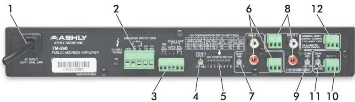
☐ Rear Panel Features
1) AC Mains
This is the AC cord for connecting to 120VAC mains, 60Hz, 24W.
2) Main Speaker Outputs
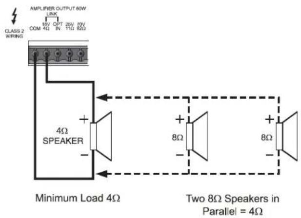
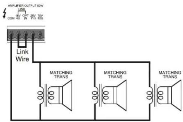
This 5.08mm Euroblock connector is used for the main speaker output wiring. For low impedance speaker loads, minimum 4 Ohm, connect between the COM and 16V/4 Ohm pins. For 25V or 70V speaker loads (70V and 100V output taps on 230VAC models), the LINK wire must first be installed between the 16V/4 Ohm pin and OPT IN pin, then connect the speaker load between COM and 25V or 70V pins.
3) Zone 2 and Preamp Outputs
In addition to the main 60 Watt amplifier output, there is a separate ZONE 2 output which is a switch selectable mix of channels 1, 2, or 3. This output is not effected by the priority ducking/mute action or by the bass/treble EQ controls.
The ZONE-2 output provides two signals; 1) a low impedance output that is capable of continuously driving 1 Watt into an 8 Ohm loudspeaker, and 2) a 600 Ohms transformer balanced output. Zone 2 output is controlled by the rear panel Zone 2 level control, as well as the three channel assign DIP switches.
The PRE OUT connection is used for driving additional external devices with the same signal that drives the main TM-360 power amplifier. The PRE OUT 600 Ohm output signal is taken before the master volume control.
4) Zone 2 Level Control
This controls the level of the Zone 2 output signal.
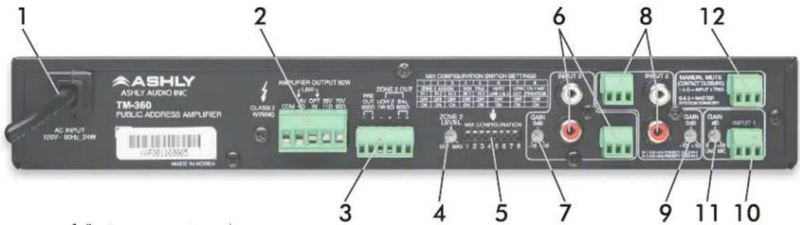
(rear panel features cont. . . .)
5) Mix Configuration DIP Switches
Switches 1, 2, and 3: Zone 2 Assign
These assign each input to Zone 2 output, post-level control. There is no effect to the main output mix.
Switches 4-5: VOX Trigger -
The TM-360 has the ability to trigger a mute on channel 2 or 3 from the presence of an audio signal on channel 1 or 2. This is called voice operated switching, or VOX. Input 2 has priority over input 3, and input 1 has priority over input 2. Input 1 also has the ability to use a contact closure trigger such as a mic push-to-talk switch for priority muting of channel 2. Additionally, input 1 can be set to have priority over both inputs 2 and 3 together (see switch 6).
The TM-360 has audio detecting LEDs on each input. When the VOX TRIG switches are set to ON for inputs 1 or 2, the same signal level which activates the LED is used as the VOX trigger. VOX mutes the dependent channel until the trigger signal falls back below the LED threshold. Each input features a rear panel gain trim that first optimizes the overall input sensitivity for each input, but can also serve to fine-tune the sensitivity of the signal detector which creates the VOX trigger point for each input.
Switch 6: Mute Link 2&3
When this switch is turned on, it sets the channel 1 VOX trigger or manual mute contact closure to mute both channels 2 and 3. If only channel 2 is to be affected, leave it off.
Switch 7: Low-Cut Filter
This switch turns on a 400Hz 6dB/oct low-cut filter affecting the main and PRE outputs but not the zone 2 outputs. This is useful for providing the proper EQ for paging horns.
Switch 8: CH I MIC Phantom Power
This provides +18V phantom power to input 1 for use with condenser and electret microphones.
6) Input 3 Connectors
3.5mm Euroblock connectors and summed stereo RCA jacks are used for input 3. If wiring an unbalanced input signal into a balanced Euroblock input, be sure to ground the (-) input pin.
7) Input 3 Gain Control
Input 3 gain trim range is adjustable from -10dB to +10dB
8) Input 2 Connectors
3.5mm Euroblock connectors and summed stereo RCA jacks are used for input 2. If wiring an unbalanced input signal into a balanced Euroblock input, be sure to ground the (-) input pin.
9) Input 2 Gain Control
Input 2 gain trim range is adjustable from -10dB to +10dB. This control is also used to fine tune the signal threshold that will trigger the muting of input 3.
10) Input 1 Connector
A 3.5mm Euroblock connector is used for input 1, and can be used as a mic level or line level input. As a balanced line input, it can connect to a telephone paging system instead of a microphone. If the input signal is unbalanced, be sure to ground the unused (-) input pin.
11) Input 1 Gain Control
Input 1 gain trim range is adjustable from 0dB to +50dB. A typical line level input setting would be close to 0dB. A typical microphone input setting would be closer to +50dB. This control is also used to fine tune the signal threshold that will trigger the muting of input 2 (or inputs 2 and 3 if linked.
12a) Manual Mute Contact Closure
Contact closure between pins 1 and G will mute input channel 2, or mute channels 2 and 3 together if they are linked using mix configuration switch #6. This is typically used when a microphone plugged into channel 1 has a push-to-talk switch, whereby the pressing of the switch not only turns on the mic but also mutes the signal on channel 2, or channels 2 and 3 if they are linked. When the switch is released, the signal on channels 2 and 3 returns.
12b) Master System Standby
This device has two power saving modes, sleep mode and master system standby. Both modes shut down the power supply to the main amplifier circuit, and are indicated by the power LED changing from blue to red.
Sleep mode happens automatically after 25 minutes of audio inactivity. Sleep mode cannot be disabled. Once in sleep mode, the amplifier is re-awakened when there is sufficient audio signal (post-input level control) to light any input signal LED.
Master system standby mode is triggered manually by contact closure of it's Euroblock connector pins G & 2. Master system standby ends when the contact closure circuit is re-opened after being closed. Master system standby always has priority over sleep mode.
□ Typical Application
Restaurant system
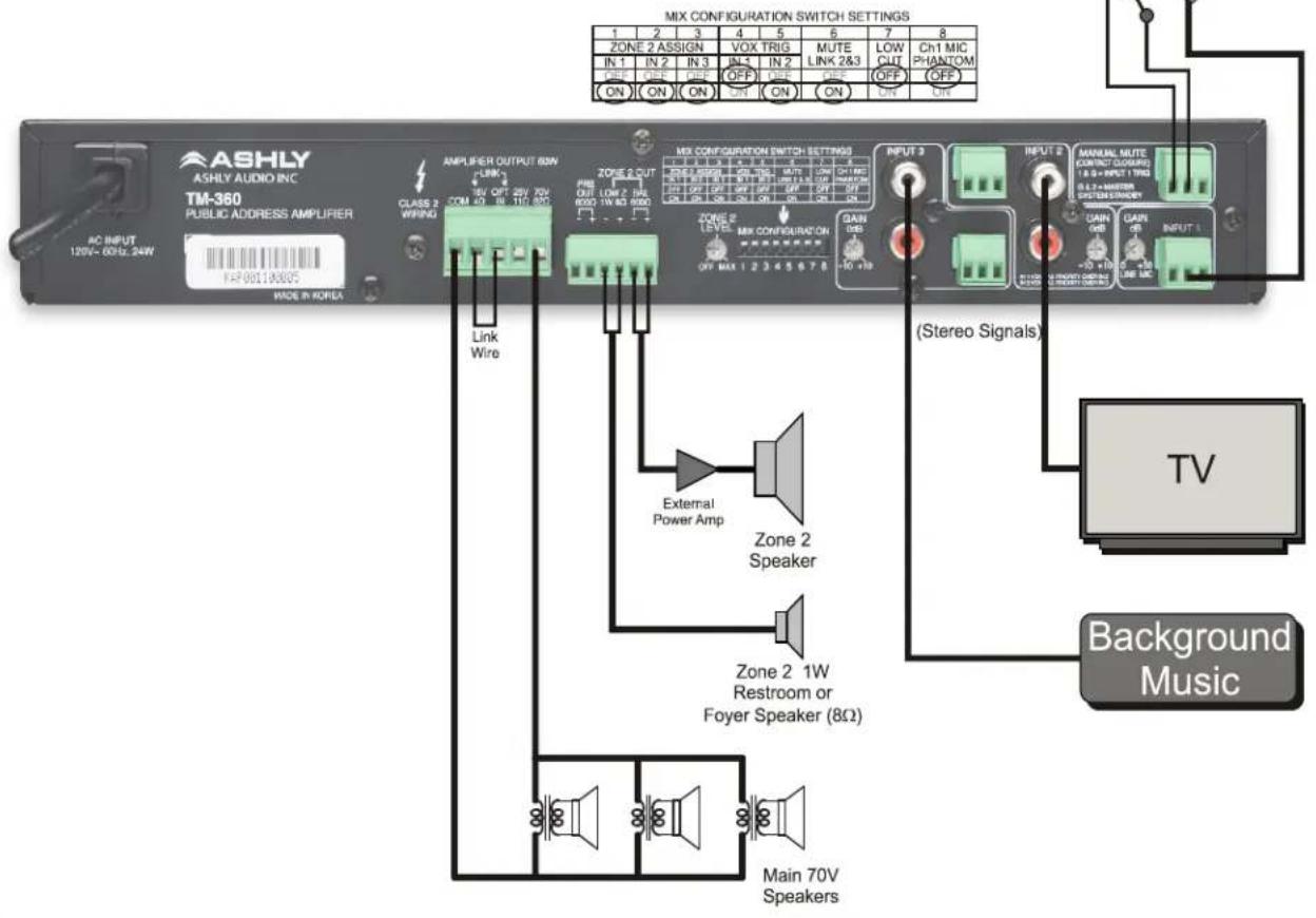
This two tiered priority ducking example allows for background music to be present on channel 3, which can be overridden by the presence of audio on channel 2 from a TV signal, both of which can be overridden by a keyed microphone announcement on channel 1. Stereo audio signals using RCA jacks are summed to mono at the input.
In this example, all three inputs are assigned to Zone 2 via the DIP switches. Because the mic is set up for push-to-talk, the IN 1 VOX trigger switch is left off. IN 2 VOX trigger is switched on however, so that signal from the TV will automatically override the background music. Mute Link is switched on so that the keyed mic will mute both Inputs 1 and 2.
A 70V distributed speaker system runs off of the main power amplifier, and an external power amplifier is run off of the Zone 2 600Ω output. A small 1W 8Ω speaker is run off of the Zone 2 Low Z output.
☐ Speaker Wiring
4Ω Speaker Wiring (60W max)
25V Speaker Wiring (60W max)
70V Speaker Wiring (60W max)
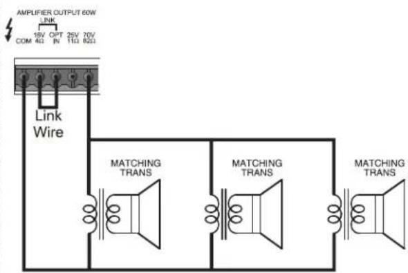
1) Low Z (4Ω), 25V, and 70V speaker loads should not be wired in combination with each other.
2) Remove power prior to making speaker connections
3) Use Class 2 Wiring.
Dimensions
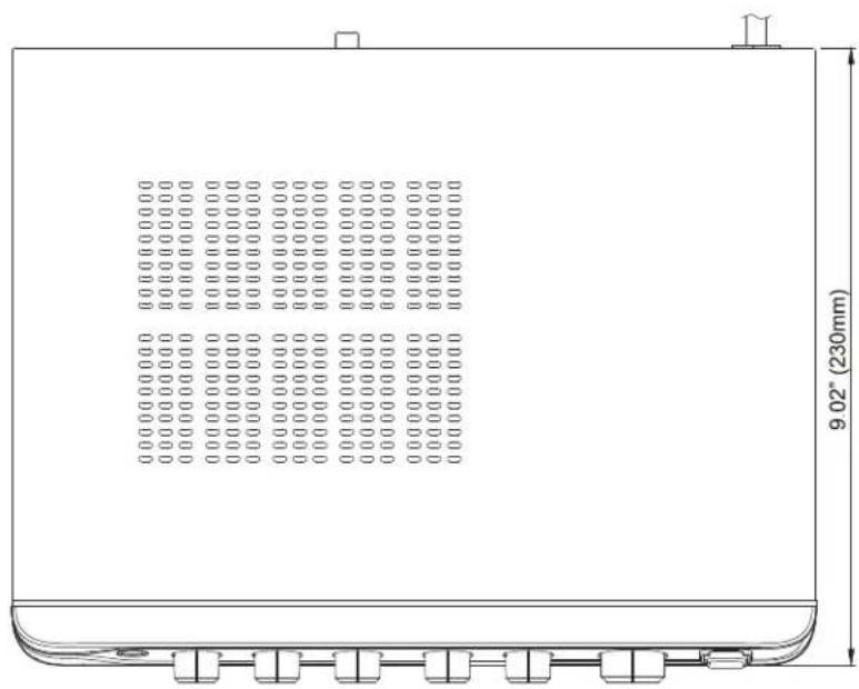
natural_image
Technical line drawing of a rectangular enclosure with internal compartments and a curved base, dimensioned as 9.02" (230mm), no text or symbols present.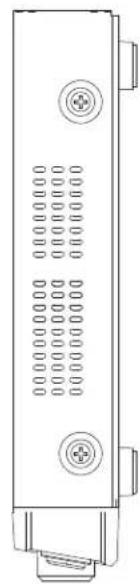
natural_image
Technical line drawing of a vertical electronic device with multiple ports and mounting feet (no text or symbols)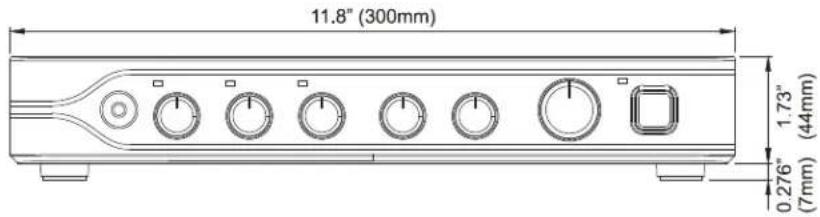
☐ Schematic Block Diagram
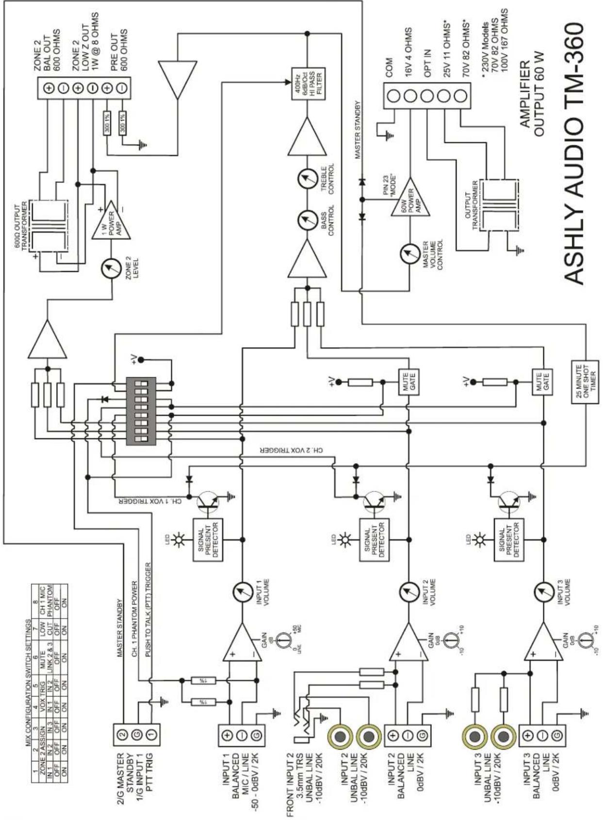
flowchart
graph TD
    subgraph Left_Circuit
        A["2/G MASTER STANDBY 1/G INPUT 1 PTT TRIG"] --> B["MASTER STANDBY"]
        B --> C["CH. 1 PHANTOM POWER PUSH TO TALK (PTT) TRIGGER"]
        D["INPUT 1 BALANCED MIC / LINE -50 - 0dBV / 2K"] --> E["+"]
        F["FRONT INPUT 2 3.5mm TRS UNBAL LINE -10dBV / 20K"] --> G["+"]
        H["INPUT 2 UNBAL LINE -10dBV / 20K"] --> I["+"]
        J["INPUT 2 BALANCED LINE 0dBV / 2K"] --> K["+"]
        L["INPUT 3 UNBAL LINE -10dBV / 20K"] --> M["+"]
        N["INPUT 3 BALANCED LINE 0dBV / 2K"] --> O["+"]
    end

    subgraph Right_Circuit
        P["SIGNAL PRESENT DETECTOR"] --> Q["CH. 1 VOX TRIGGER"]
        R["SIGNAL PRESENT DETECTOR"] --> S["CH. 2 VOX TRIGGER"]
        T["SIGNAL PRESENT DETECTOR"] --> U["CH. 2 VOX TRIGGER"]
        V["SIGNAL PRESENT DETECTOR"] --> W["CH. 2 VOX TRIGGER"]
        X["SIGNAL PRESENT DETECTOR"] --> Y["CH. 2 VOX TRIGGER"]
        Z["SIGNAL PRESENT DETECTOR"] --> AA["CH. 2 VOX TRIGGER"]
        AB["SIGNAL PRESENT DETECTOR"] --> AC["CH. 2 VOX TRIGGER"]
        AD["SIGNAL PRESENT DETECTOR"] --> AE["CH. 2 VOX TRIGGER"]
        AF["SIGNAL PRESENT DETECTOR"] --> AG["CH. 2 VOX TRIGGER"]
        AH["SIGNAL PRESENT DETECTOR"] --> AI["CH. 2 VOX TRIGGER"]
        AJ["SIGNAL PRESENT DETECTOR"] --> AK["CH. 2 VOX TRIGGER"]
        AL["SIGNAL PRESENT DETECTOR"] --> AM["CH. 2 VOX TRIGGER"]
        AN["SIGNAL PRESENT DETECTOR"] --> AO["CH. 2 VOX TRIGGER"]
        AP["SIGNAL PRESENT DETECTOR"] --> AQ["CH. 2 VOX TRIGGER"]
        AR["SIGNAL PRESENT DETECTOR"] --> AS["CH. 2 VOX TRIGGER"]
        AT["SIGNAL PRESENT DETECTOR"] --> AU["CH. 2 VOX TRIGGER"]
        AV["SIGNAL PRESENT DETECTOR"] --> AW["CH. 2 VOX TRIGGER"]
        AX["SIGNAL PRESENT DETECTOR"] --> AY["CH. 2 VOX TRIGGER"]
        AZ["SIGNAL PRESENT DETECTOR"] --> BA["CH. 2 VOX TRIGGER"]
        BB["SIGNAL PRESENT DETECTOR"] --> BC["CH. 2 VOX TRIGGER"]
        BD["SIGNAL PRESENT DETECTOR"] --> BE["CH. 2 VOX TRIGGER"]
        BF["SIGNAL PRESENT DETECTOR"] --> BG["CH. 2 VOX TRIGGER"]
        BH["SIGNAL PRESENT DETECTOR"] --> BI["CH. 2 VOX TRIGGER"]
        BJ["SIGNAL PRESENT DETECTOR"] --> BK["CH. 2 VOX TRIGGER"]
        BL["SIGNAL PRESENT DETECTOR"] --> BM["CH. 2 VOX TRIGGER"]
        BN["SIGNAL PRESENT DETECTOR"] --> BO["CH. 2 VOX TRIGGER"]
        BP["SIGNAL PRESENT DETECTOR"] --> BQ["CH. 2 VOX TRIGGER"]
        BR["SIGNAL PRESENT DETECTOR"] --> BS["CH. 2 VOX TRIGGER"]
        BT["SIGNAL PRESENT DETECTOR"] --> BU["CH. 2 VOX TRIGGER"]
        BV["SIGNAL PRESENT DETECTOR"] --> BW["CH. 2 VOX TRIGGER"]
        BX["SIGNAL PRESENT DETECTOR"] --> BY["CH. 2 VOX TRIGGER"]
        BZ["SIGNAL PRESENT DETECTOR"] --> CA["CH. 2 VOX TRIGGER"]
        CB["SIGNAL PRESENT DETECTOR"] --> CC["CH. 2 VOX TRIGGER"]
        DD["SIGNAL PRESENT DETECTOR"] --> EE["CH. 2 VOX TRIGGER"]
    end

    subgraph Right_Circuit
        F --> F1["+V"]
        G --> G1["BASS CONTROL"]
        H --> H1["TREBLE CONTROL"]
        I --> I1["400Hz 6dB/Oct HI PASS FILTER"]
        J --> J1["MASTER STANDBY"]
        K --> K1["PIN 23 "MODE""]
        L --> L1["60W POWER AMP"]
        M --> M1["MASTER VOLUME CONTROL"]
        N --> N1["OUTPUT TRANSFORMER"]
        O --> O1["*230V Models 70V 82 OHMS 100V 167 OHMS"]

    end

    subgraph Left_Peak
        P --> P1["+V"]
        Q --> Q1["MUTE GATE"]
        R --> R1["MUTE GATE"]
        S --> S1["+V"]
        T --> T1["MUTE GATE"]
        U --> U1["+V"]
    end

    subgraph Right_Peak
        U1 --> U1a["BASS CONTROL"]
        U1a --> U1b["TREBLE CONTROL"]
        U1b --> U1c["400Hz 6dB/Oct HI PASS FILTER"]

    subgraph Left_Detek
        U1a --> U1a1["BASS CONTROL"]
        U1a --> U1a2["TREBLE CONTROL"]
    end

    subgraph Right_Detek
        U1a1 --> U1a1a["BASS CONTROL"]
        U1a1a --> U1a1b["BASS CONTROL"]
    end

    style Left_Circuit fill:#f9f,stroke:#333
    style Right_Circuit fill:#ccf,stroke:#333
Specifications
| TM-360 | ||||
| Rated Output Power (THD 1%) | 60W (RMS) | |||
| Output Voltage /Impedance | USA/CANADA & Associated | 4Ω/15.5V | 10.4Ω/25V | 82Ω/70V |
| EC & Associated, JAPAN | 4Ω/15.5V | 82Ω/70V | 167Ω/100V | |
| Frequency Response (1W@1KHz) | Input 1, 2, 3 | +1/-3dB, 80Hz-15kHz | ||
| THD (60W @ 1kHz) | < 1% | |||
| S/N Ratio (60W@1KHz A-weighted) | Input 1, 2, 3 | >80dB | ||
| Input Sensitivity | Input 1 | -10dBV to -50dBV | ||
| Input 2, 3 | 0dBV to -20dBV | |||
| Tone Control | Treble (10kHz) | ±10dB | ||
| Bass (100Hz) | ±10dB | |||
| Residual Noise (Input 1-3 vol min, tone at center) | Master volume min | -72dB | ||
| Master volume max | -57dB | |||
| Zone 2 Output | Rated power 8Ω (RMS, THD 3%) | 1W | ||
| Bal 600Ω | 2.4V | |||
| PRE Out (input -10dBV) | 0dBV | |||
| Mix Configuration Switches | SW1 | Zone 2 Assign Input 1 | ||
| SW2 | Zone 2 Assign Input 2 | |||
| SW3 | Zone 2 Assign Input 3 | |||
| SW4 | VOX Trigger Input 1 | |||
| SW5 | VOX Trigger Input 2 | |||
| SW6 | Mute Link Input 2 & 3 | |||
| SW7 | Low-Cut, 400Hz 6dB/Oct. | |||
| SW8 | Ch1 Phantom Power, +18V | |||
| Manual Mute Contact Closure | Pins 1 & G = Input 1 Mute Trigger | |||
| Master System Standby Contact Closure | Pins G & 2 = Power Standby, with priority over sleep mode | |||
| Sleep Mode (Power Standby) | Sleep after 25 minutes inactivity, wake when input LED shows signal | |||
| AC Requirements | 120VAC, 60Hz, 24W (USA & Canada and Associated) 230VAC, 50/60HZ, 24W (EC and Associated, Japan) | |||
| Line Current Draw (120VAC 60Hz) (For 230VAC models, divide line current draw values by 2) | Standby | 0.15A | ||
| Idle | 0.24A | |||
| 1/8th Power Pink Noise | 0.38A | |||
| 1/3th Power Sine Wave | 0.66A | |||
| Thermal Dissipation (BTU/hr) | Standby | 26 | ||
| Idle | 43 | |||
| 1/8th Power Pink Noise | 53 | |||
| 1/3th Power Sine Wave | 75 | |||
| Environmental | 40°F ~ 120°F (4° ~ 49°C) non-condensing | |||
| Weight | 8.6lb (3.9kg) | |||
| Dimensions | 11.8"W x 2"H x 9.02"D (300mm x 51mm x 230mm) | |||
* Specifications and design subject to change without notice. Note: 0dBV = 1V
Ashly Audio Inc. LIMITED WARRANTY (USA ONLY)
(Other countries please contact your respective distributor or dealer)
For units purchased in the USA, warranty service for this unit shall be provided by ASHLY AUDIO, INC. in accordance with the following warranty statement.
ASHLY AUDIO, INC. warrants to the owner of this product that it will be free from defects in workmanship and materials for a period of FIVE years from the original-date-of-purchase. ASHLY AUDIO INC. will without charge, repair or replace at its discretion, any defective product or component parts upon prepaid delivery of the product to the ASHLY AUDIO, INC. factory service department, accompanied with a proof of original-date-of-purchase in the form of a valid sales receipt. This warranty gives you specific legal rights, and you may also have other rights, which vary from state to state.
EXCLUSIONS: This warranty does not apply in the event of misuse, neglect, or as a result of unauthorized alterations or repairs made to the product. This warranty is void if the serial number is altered, defaced, or removed. ASHLY AUDIO, INC. reserves the right to make changes in design, or make additions to, or improvements upon, this product without any obligation to install the same on products previously manufactured.
Any implied warranties, which may arise under the operation of state law, shall be effective only for FIVE years from the original-date-of-purchase of the product. ASHLY AUDIO, INC. shall be obligated to only correct defects in the product itself. ASHLY AUDIO, INC. is not liable for any damage or injury, which may result from, or be incidental to, or a consequence of, such defects. Some states do not allow limitations on how long an implied warranty lasts, or the exclusion, or limitation of incidental or consequential damages, so the above limitations or exclusions may not apply to you.
OBTAINING WARRANTY SERVICE:
For warranty service in the United States, please follow this procedure:
1) Return the product to ASHLY AUDIO, INC. freight prepaid, with a written statement describing the defect and application that the product is used in. ASHLY AUDIO, INC. will examine the product and perform any necessary service, including replacement of defective parts, at no further cost to you.
2) Ship your product to:
ASHLY AUDIO, INC.
Attention: Service Department
847 Holt Road
Webster, NY 14580-9103
(This page intentionally left blank)
(This page intentionally left blank)
- Public Address Amplifier
- Operating Manual
- Table Of Contents
- Overview
- Front Panel Features
- 1) Input 2 Jack
- 2) Input Signal LEDs (3)
- 3) Input Level Controls (3)
- 4) Bass and Treble Controls
- 5) Master Volume Control
- 6) Power LED
- 7) Power Switch
- ☐ Rear Panel Features
- 1) AC Mains
- 2) Main Speaker Outputs
- 3) Zone 2 and Preamp Outputs
- 4) Zone 2 Level Control
- 5) Mix Configuration DIP Switches
- Switches 1, 2, and 3: Zone 2 Assign
- Switches 4-5: VOX Trigger -
- Switch 6: Mute Link 2&3
- Switch 7: Low-Cut Filter
- Switch 8: CH I MIC Phantom Power
- 6) Input 3 Connectors
- 7) Input 3 Gain Control
- 8) Input 2 Connectors
- 9) Input 2 Gain Control
- 10) Input 1 Connector
- 11) Input 1 Gain Control
- 12a) Manual Mute Contact Closure
- 12b) Master System Standby
- □ Typical Application
- Restaurant system
- ☐ Speaker Wiring
- Dimensions
- Ashly Audio Inc. LIMITED WARRANTY (USA ONLY)
- (Other countries please contact your respective distributor or dealer)
- OBTAINING WARRANTY SERVICE:
Brand : Ashly
Model : TM-360
Category : Receiver