TM-335 - Receiver Ashly - Free user manual and instructions
Find the device manual for free TM-335 Ashly in PDF.


| Product Type | Professional Audio Receiver |
| Brand | Ashly |
| Model | TM-335 |
| Rack Mountable | Yes, standard 19-inch rack |
| Dimensions (W x H x D) | 19 x 1.75 x 10 inches |
| Weight | 10 lbs |
| Power Supply | 100-240V AC, 50/60 Hz |
| Power Consumption | 50W maximum |
| Inputs | XLR, 1/4" TRS, RCA |
| Outputs | XLR, 1/4" TRS, Speaker terminals |
| Frequency Response | 20 Hz - 20 kHz |
| Signal-to-Noise Ratio | >90 dB |
| Total Harmonic Distortion | <0.05% |
| Cooling | Fan-cooled, temperature controlled |
| Chassis Material | Steel with black finish |
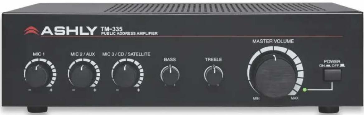
| Front Panel Controls | Volume knob, power switch, LED indicators |
| Rear Panel Features | Binding post outputs, fuse holder, IEC power inlet |
| Protection Features | Short circuit, thermal, overload |
| Operating Temperature | 32°F to 104°F (0°C to 40°C) |
| Maintenance | Keep vents clear, clean with dry cloth, avoid moisture |
| Safety Certifications | CE, RoHS |
Frequently Asked Questions - TM-335 Ashly
User questions about TM-335 Ashly
0 question about this device. Answer the ones you know or ask your own.
Ask a new question about this device
Download the instructions for your Receiver in PDF format for free! Find your manual TM-335 - Ashly and take your electronic device back in hand. On this page are published all the documents necessary for the use of your device. TM-335 by Ashly.
USER MANUAL TM-335 Ashly
Public Address Mixer/Amplifier
Operating Manual
The lightning flash with arrowhead symbol, within an equilateral triangle, is intended to alert the user to the presence of uninsulated "dangerous voltage" within the product's enclosure that may be of sufficient magnitude to constitute a risk of electric shock to persons. The exclamation point within an equilateral triangle is intended to alert the user to the presence of important operating and maintenance instructions in the literature accompanying the device.
- Read these instructions.
- Keep these instructions.
- Heed all warnings.
- Follow all instructions.
- To reduce the risk of fire or electric shock, do not expose this apparatus to rain or moisture.
- Do not use this apparatus near water.
- Clean only with dry cloth.
- Do not block any ventilation openings. Install in accordance with the manufacturer's instructions.
- Do not install near any heat sources such as radiators, heat registers, stoves, or other apparatus.
- Do not defeat the safety purpose of the polarized or grounding-type plug. A polarized plug has two blades with one wider than the other. A grounding type plug has two blades and a third grounding prong. The wide blade or the third prong are provided for your safety. If the provided plug does not fit into your outlet, consult an electrician for replacement of the obsolete outlet.
- Protect the power cord from being walked on or pinched particularly at plugs, convenience receptacles, and the point where they exit from the apparatus.
- Only use attachments/accessories specified by the manufacturer.
- Use only with the cart, stand, tripod, bracket, or table specified by the manufacturer, or sold with the apparatus. When a cart is used, use caution when moving the cart/apparatus combination to avoid injury from tip-over.
- Unplug this apparatus during lightning storms or when unused for long periods of time.
- Refer all servicing to qualified service personnel. Servicing is required when the apparatus has been damaged in any way, such as power-supply cord or plug is damaged, liquid has been spilled or objects have fallen into the apparatus, the apparatus has been exposed to rain or moisture, does not operate normally, or has been dropped.
This device complies with part 15 of the FCC Rules. Operation is subject to the following two conditions:
- This device may not cause harmful interference
- This device must accept any interference received, including interference that may cause undesired operation.
WARNING:
THIS APPARATUS MUST BE EARTHED
Table Of Contents
Safety Instructions....2
Front Panel Features 4
Rear Panel Features .... 5
Speaker Wiring 7
Typical Application 8
Dimensions 9
Schematic Block Diagram 10
Specifications....11
Limited Warranty....12
Overview
The Ashly TM-335 is a table-top 35W mono mixer amplifier, suitable for applications requiring background music with priority paging/ducking from either a microphone or telephone paging system input. The TM-335 includes the following features:
- 35W mono speaker output with 4Ω, 8Ω, 25V, and 70V taps on Euroblock 230V export models have 4Ω, 8Ω, 70V, and 100V output taps
- Euroblock telephone input with rear panel level and ducking depth controls
- Euroblock mic input with rear panel ducking depth control
- Selectable Euroblock mic input or summed stereo aux input on Euroblock or 3.5mm jack
- Selectable Euroblock mic input or summed stereo CD/Satellite input on RCA jack
- Front panel level and master volume controls
- Front panel bass and treble controls
- Limited five year warranty
• Safety/Compliance: cCSAus, CE, FCC, RoHS
Please read this entire manual to fully understand the features and proper use of this product.
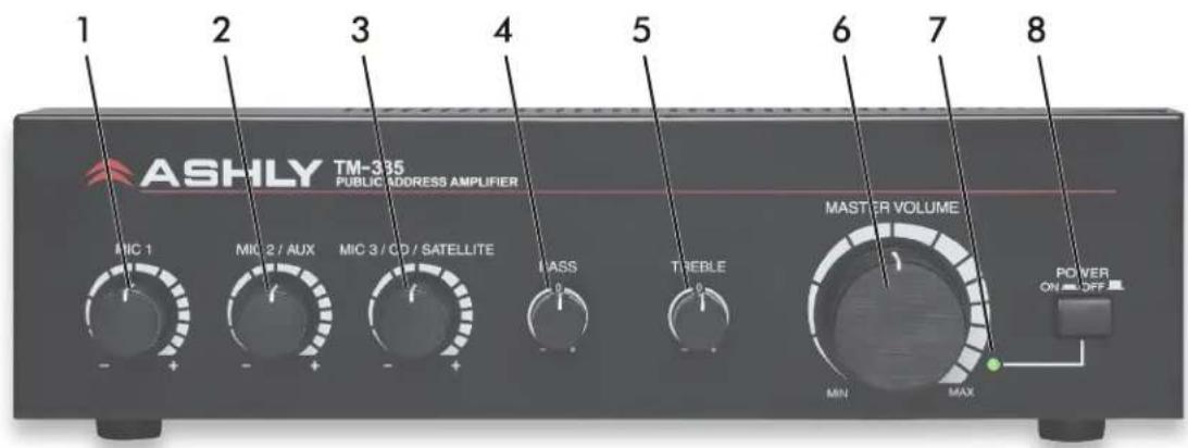
Front Panel Features
1) Mic 1 Level
This controls the level of Mic 1 input.
2) Mic 2/Aux Level
This controls the level of the selectable Mic 2 or summed Stereo Aux inputs.
3) Mic 3/CD/Satellite Input Level
This controls the level of the selectable Mic 3 or summed stereo CD/Satellite inputs.
4) Bass
This provides control of the low frequency response with up to 10dB of boost or cut.
5) Treble
This provides control of the high frequency response with up to 10dB of boost or cut.
6) Master Volume
This controls the amplifier output level.
7) Power LED
This LED lights green when the unit is powered on.
8) Power Switch
This switch turns the power on or off
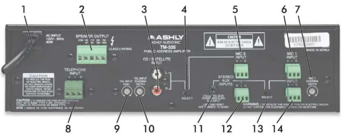
☐ Rear Panel Features
1) AC Mains
This is the AC cord for connecting to 120VAC mains, 60Hz, 40W. Certain export models connect to 230V and are labelled accordingly.
2) Main Speaker Outputs
This 5.08mm Euroblock connector is used for speaker output wiring. For low impedance speaker loads, connect between the COM and 12V/4Ω terminal or COM and 17V/8Ω terminal. For 25V or 70V distributed speaker applications, connect the speakers between COM and 25V or 70V terminals, depending on the transformers/speakers used. For distributed speaker loads on 230V export models, connect between COM and 70V or 100V terminals.
3) CD/Satellite Input
These RCA inputs accept a stereo line level signal and sum them to mono on channel 3 input. To use the CD/Satellite RCA inputs, be sure to set the channel 3 Select switch (#4 below) to the left.
4) Input Select Switch
This switch selects either the stereo line level input on RCA jacks, or mic level input on the MIC 3 Euroblock connector.
5) MIC 3 Input
This 3.5mm Euroblock connector is used for MIC 3 input. To use the MIC 3 input, set the channel 3 SELECT switch (#4 above) to the right. Wire the microphone (+) signal to pin 1, the (-) signal to pin 2, and (G) to pin 3. If wiring an unbalanced mic input signal into a balanced Euroblock input, be sure to ground the (-) input pin.
6) MIC 1 Input
This 3.5mm Euroblock connector is used for MIC 1 input. Wire the microphone (+) signal to pin 1, the (-) signal to pin 2, and (G) to pin 3. If wiring an unbalanced mic input signal into a balanced Euroblock input, be sure to ground the (-) input pin. MIC 1 input has ducking priority over MIC 2 and MIC 3 inputs, with an adjustable ducking depth control. There is no phantom power available on the TM-335.
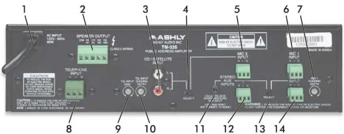
(rear panel features continued . . .)
7) MIC 1 Ducking Depth
This control adjusts the ducking depth of channels 2 and 3 when MIC 1 input has signal present. Turning the control clockwise increases the amount of ducking.
8) Telephone Input
This 5.08mm Euroblock connector is used to connect with a 0.3V 600Ω output from a telephone paging system. Wire the telephone input (+) signal to pin 1, the (-) signal to pin 2, and (G) to pin 3. If wiring an unbalanced signal into the balanced telephone input, be sure to ground the (-) input pin. The telephone input has ducking priority over channels 2 and 3 along with MIC 1 input.
9) Telephone Input Gain
This adjusts the level of the Telephone input to the main output.
10) Telephone Input Ducking Depth
This control adjusts the ducking depth, or decrease in volume, of channels 2 and 3 when the telephone input has signal present. Turning the control clockwise increases the amount of ducking.
11) Stereo Aux Input - 3.5mm Jack
This 3.5mm Tip Ring Sleeve (TRS) jack sums its left and right signals into mono, and overrides the Euroblock Stereo Aux input when plugged in. To use this input, the select switch (#13) must be pushed left.
12) Stereo Aux Input - Euroblock
This Euroblock input connector sums its left and right signals into mono, and is overridden by the 3.5mm stereo aux input. To use this input, the select switch (#13) must be pushed left.
13) Select Switch
This switch must be pushed left to use either the 3.5mm stereo aux input or the euroblock stereo aux input. It must be pushed right to use MIC 2 input.
14) MIC 2 Input
This 3.5mm Euroblock connector is used for MIC 2 input. To use the MIC 2 input, push the channel 2 Select switch (#13 above) to the right. Wire the microphone (+) signal to pin 1, the (-) signal to pin 2, and (G) to pin 3. If wiring an unbalanced mic input signal into a balanced Euroblock input, be sure to ground the (-) input pin.
☐ Speaker Wiring
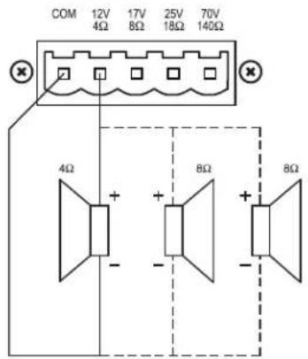
- Before connecting speakers to the TM-335 unit, be sure to disconnect the AC power cable.
- Make certain that the load impedance is not less than the rated impedance indicated.
- Low Z (4Ω or 8Ω), 25V, and 70V speaker loads should not be wired in combination with each other.
- Use class 2 wiring.
For the 4Ω low impedance terminal, connect as shown below, with the negative (-) speaker wire connected to the COM terminal and the positive (+) speaker wire connected to the 4Ω terminal. Note from the illustration how two 8Ω speakers can be wired in parallel to make a 4Ω load.
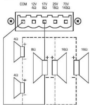
For the 8Ω low impedance terminal, connect as shown below, with the negative (-) speaker wire connected to the COM terminal and the positive (+) speaker wire connected to the 8Ω terminal. Note from the illustration how two 4Ω speakers can be wired in series, or two 16Ω speakers can be wired in parallel to make an 8Ω load.
FOR 4Ω TERMINAL
FOR 8Ω TERMINAL
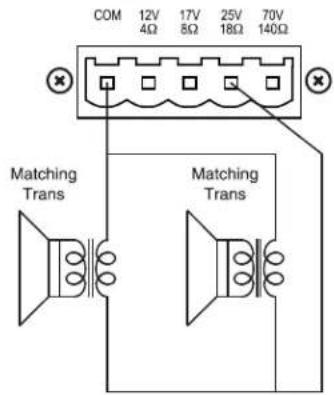
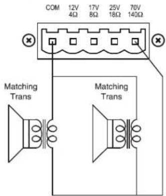
For 25V and 70V terminals, connect with matching transformers as shown below. Note: 230V export models have 70V and 100V taps instead of 25V and 70V.
FOR 25V TERMINAL
FOR 70V TERMINAL
□ Typical Application
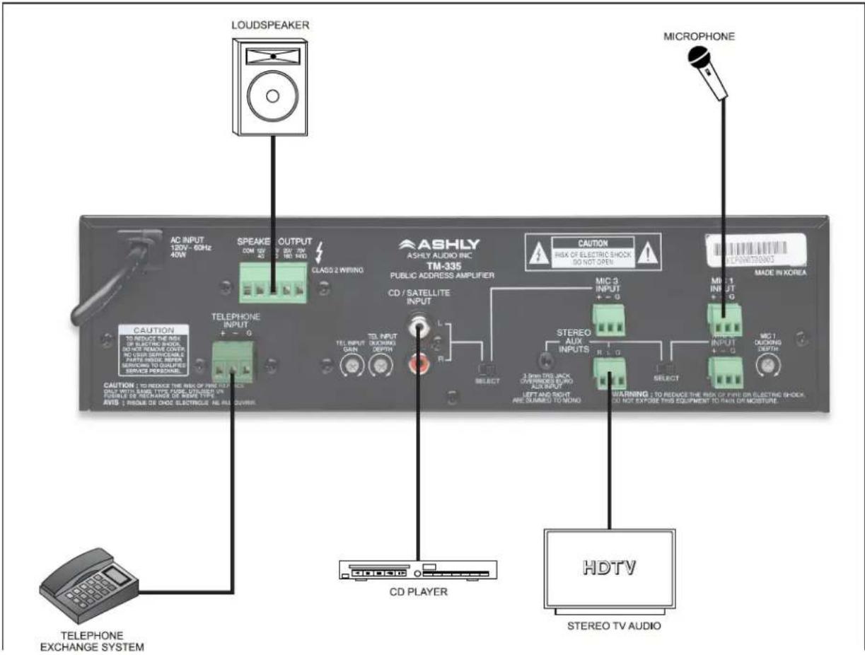
In this example, a dynamic microphone is connected to MIC 1, a stereo tv output is wired to channel 2, and a CD player or satellite receiver is connected to channel 3 using the RCA inputs. A telephone system paging output is connected to the telephone input. Signal present on either MIC 1 or on the telephone input will duck, or temporarily lower the volume, of both the TV and CD/Satellite inputs. The amount of ducking is determined separately by the rear panel ducking depth controls for telephone and MIC 1 inputs. Turning the ducking depth controls clockwise increases the amount of ducking on channels 2 and 3 when that input is active.
Loudspeaker(s) are wired to either the 4Ω, 8Ω, 25V, or 70V output terminals. Make certain to use only one type of speaker output, and to connect a total speaker impedance that is the same or higher than the rated output impedance for the terminal used.
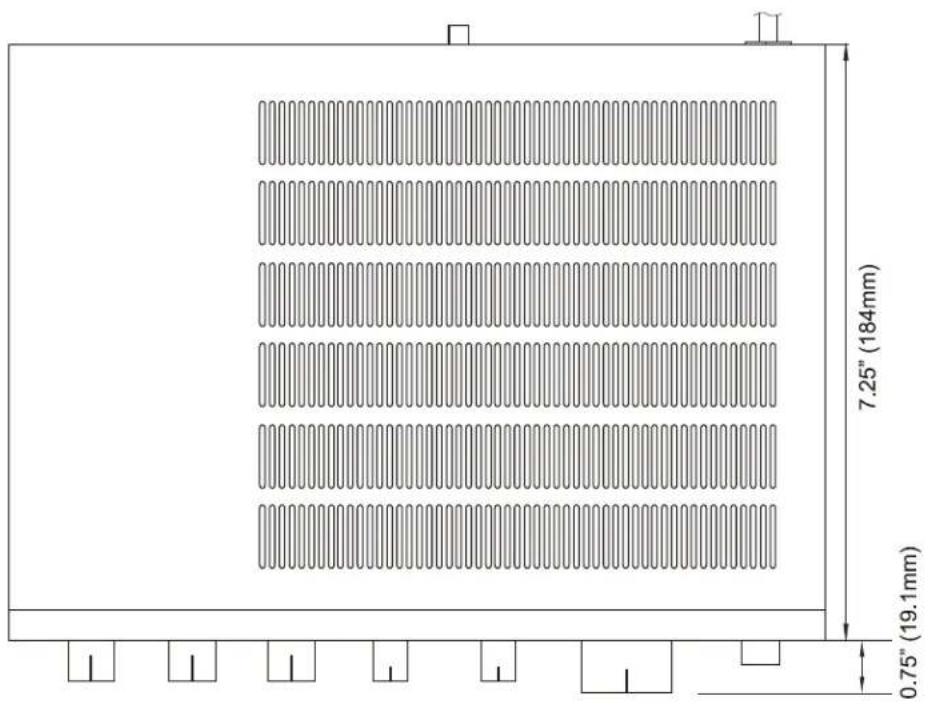
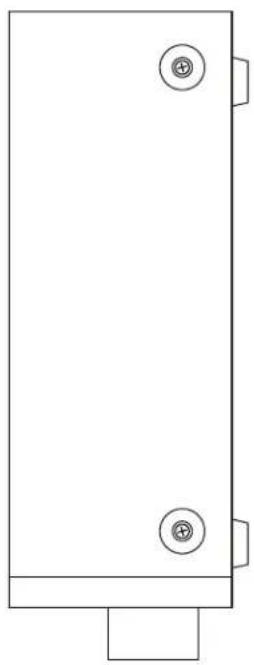
Dimensions
natural_image
Simple line drawing of a rectangular panel with two circular buttons and a base (no text or symbols)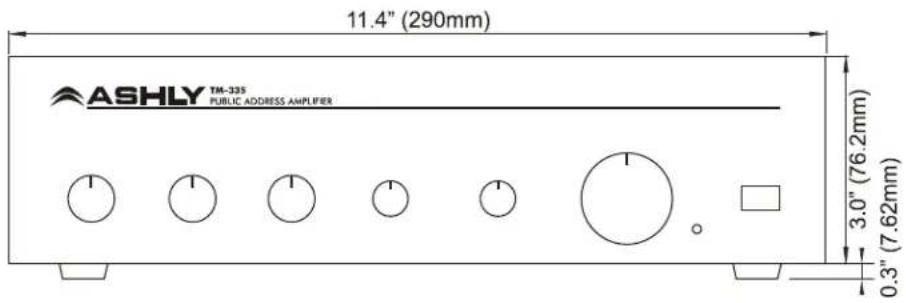
☐ Schematic Block Diagram
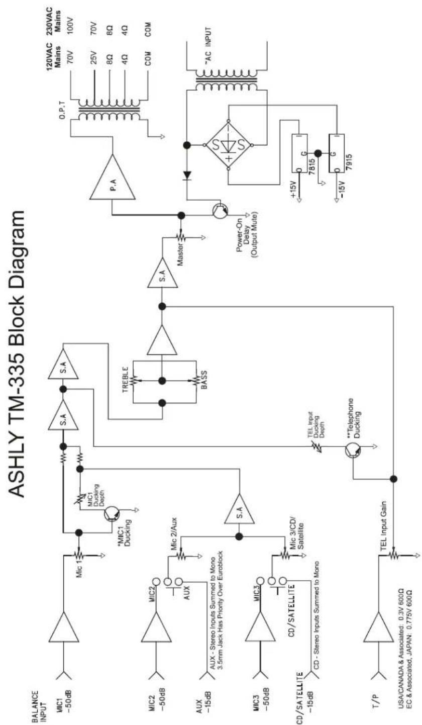
flowchart
graph TD
    A["Balance INPUT"] --> B["MIC1 -50dB"]
    B --> C["+"]
    C --> D["Mic 1"]
    D --> E["S.A"]
    E --> F["S.A"]
    F --> G["TREBLE"]
    G --> H["BASS"]
    H --> I["S.A"]
    I --> J["P.A"]
    J --> K["120VAC Mains 70V 100V"]
    K --> L["230VAC Mains 25V 70V 8Ω 4Ω 4Ω"]
    L --> M["COM"]
    M --> N["AC INPUT"]
    N --> O["Power-On Delay (Output Mute)"]
    O --> P["+15V 7815 G"]
    P --> Q["-15V 7915 G"]
    Q --> R["+15V 7815 G"]
    R --> S["AC INPUT"]
    S --> T["Power-On Delay (Output Mute)"]
    T --> U["Power-On Delay (Output Mute)"]
    U --> V["Power-On Delay (Output Mute)"]
    V --> W["Power-On Delay (Output Mute)"]
    W --> X["Power-On Delay (Output Mute)"]
    X --> Y["Power-On Delay (Output Mute)"]
    Y --> Z["Power-On Delay (Output Mute)"]
    Z --> AA["Power-On Delay (Output Mute)"]
    AA --> AB["Power-On Delay (Output Mute)"]
    AB --> AC["Power-On Delay (Output Mute)"]
    AC --> AD["Power-On Delay (Output Mute)"]
    AD --> AE["Power-On Delay (Output Mute)"]
    AE --> AF["Power-On Delay (Output Mute)"]
    AF --> AG["Power-On Delay (Output Mute)"]
    AG --> AH["Power-On Delay (Output Mute)"]
    AH --> AI["Power-On Delay (Output Mute)"]
    AI --> AJ["Power-On Delay (Output Mute)"]
    AJ --> AK["Power-On Delay (Output Mute)"]
    AK --> AL["Power-On Delay (Output Mute)"]
    AL --> AM["Power-On Delay (Output Mute)"]
    AM --> AN["Power-On Delay (Output Mute)"]
    AN --> AO["Power-On Delay (Output Mute)"]
    AO --> AP["Power-On Delay (Output Mute)"]
    AP --> AQ["Power-On Delay (Output Mute)"]
    AQ --> AR["Power-On Delay (Output Mute)"]
    AR --> AS["Power-On Delay (Output Mute)"]
    AS --> AT["Power-On Delay (Output Mute)"]
    AT --> AU["Power-On Delay (Output Mute)"]
    AU --> AV["Power-On Delay (Output Mute)"]
    AV --> AW["Power-On Delay (Output Mute)"]
    AW --> AX["Power-On Delay (Output Mute)"]
    AX --> AY["Power-On Delay (Output Mute)"]
    AY --> AZ["Power-On Delay (Output Mute)"]
    AZ --> BA["Power-On Delay (Output Mute)"]
    BA --> BB["Power-On Delay (Output Mute)"]
    BB --> BC["Power-On Delay (Output Mute)"]
    BC --> BD["Power-On Delay (Output Mute)"]
    BD --> BE["Power-On Delay (Output Mute)"]
    BE --> BF["Power-On Delay (Output Mute)"]
    BF --> BG["Power-On Delay (Output Mute)"]
    BG --> BH["Power-On Delay (Output Mute)"]
    BH --> BI["Power-On Delay (Output Mute)"]
    BI --> BJ["Power-On Delay (Output Mute)"]
    BJ --> BK["Power-On Delay (Output Mute)"]
    BK --> BL["Power-On Delay (Output Mute)"]
    BL --> BM["Power-On Delay (Output Mute)"]
    BM --> BN["Power-On Delay (Output Mute)"]
    BN --> BO["Power-On Delay (Output Mute)"]
    BO --> BP["Power-On Delay (Output Mute)"]
    BP --> BQ["Power-On Delay (Output Mute)"]
    BQ --> BR["Power-On Delay (Output Mute)"]
    BR --> BS["Power-On Delay (Output Mute)"]
    BS --> BT["Power-On Delay (Output Mute)"]
    BT --> BU["Power-On Delay (Output Mute)"]
    BU --> BV["Power-On Delay (Output Mute)"]
    BV --> BW["Power-On Delay (Output Mute)"]
    BW --> BX["Power-On Delay (Output Mute)"]
    BX --> BY["Power-On Delay (Output Mute)"]
    BY --> BZ["Power-On Delay (Output Mute)"]
    BZ --> CA["Power-On Delay (Output Mute)"]
    CA --> CB["Power-On Delay (Output Mute)"]
    CB --> CC["Power-On Delay (Output Mute)"]
    CC --> CD["Power-On Delay (Output Mute)"]
    CD --> CE["Power-On Delay (Output Mute)"]
    CE --> CF["Power-On Delay (Output Mute)"]
    CF --> CG["Power-On Delay (Output Mute)"]
    CG --> CH["Power-On Delay (Output Mute)"]
    CH --> CI["Power-On Delay (Output Mute)"]
    CI --> CJ["Power-On Delay (Output Mute)"]
    CJ --> CK["Power-On Delay (Output Mute)"]
    CK --> CL["Power-On Delay (Output Mute)"]
*Mic 1 has ducking priority over mic 2 and mic 3 channels **Telephone input has ducking priority over mic 1, mic 2, and mic 3 channels
Specifications
| TM-335 | |||||
| Rated Output Power (at T.H.D : 5% | 35W (RMS) | ||||
| Frequency Response (+0, -3dB) | Mic 1, 2, 3 | 130Hz-20kHz | |||
| Aux | 50Hz-20kHz | ||||
| CD/Satellite | 50Hz-20kHz | ||||
| Telephone | 330Hz-3kHz | ||||
| T.H.D (at Rated Output, 1kHz | Less Than 5% | ||||
| S/N(26dB Gain) | Mic 1, 2, 3 | 89dB | |||
| Aux, CD/Satellite, Telephone | 89dB | ||||
| Input Sensitivity /Impedance | Mic 1, 2, 3 | -50dBV/600Ω | |||
| Aux | -15dBV/10kΩ | ||||
| CD/Satellite | -15dBV/10kΩ | ||||
| Telephone | 0.3V/600Ω | ||||
| Output Voltage /Impedance | EC & Associated (230V) | 4Ω/11.8V | 8Ω/16.7V | 140Ω/70V | 285Ω/100V |
| USA/CANADA & Associated | 4Ω/11.8V | 8Ω/16.7V | 18Ω/25V | 140Ω/70V | |
| Operating Temperature | -10°C ~ +40°C | ||||
| Power Source | 100–120VAC or 220–240VAC; 50/60Hz(Supplied AC mains transformer depends on country requirements) | ||||
| Line Current Draw (120VAC 60Hz)(For 230VAC 50Hz Models,Divide Line Current Draw Values by 2) | Idle | 0.11A | |||
| 1/8th Power Pink Noise | 0.27A | ||||
| 1/3th Power Sine Wave | 0.31A | ||||
| Thermal Dissipation(BTU/hr) | Idle | 30 | |||
| 1/8th Power Pink Noise | 68 | ||||
| 1/3th Power Sine Wave | 75 | ||||
| Weight | 4.4kg/9.7lb | ||||
| Dimensions | 290(W)X76(H)X185(D)mm/11.4(W)X3(H)X7.3(D)in | ||||
* Specifications and design subject to change without notice. Note: 0dBV = 1V
Ashly Audio Inc. LIMITED WARRANTY (USA ONLY)
(Other countries please contact your respective distributor or dealer)
For units purchased in the USA, warranty service for this unit shall be provided by ASHLY AUDIO, INC. in accordance with the following warranty statement.
ASHLY AUDIO, INC. warrants to the owner of this product that it will be free from defects in workmanship and materials for a period of FIVE years from the original-date-of-purchase. ASHLY AUDIO INC. will without charge, repair or replace at its discretion, any defective product or component parts upon prepaid delivery of the product to the ASHLY AUDIO, INC. factory service department, accompanied with a proof of original-date-of-purchase in the form of a valid sales receipt. This warranty gives you specific legal rights, and you may also have other rights, which vary from state to state.
EXCLUSIONS: This warranty does not apply in the event of misuse, neglect, or as a result of unauthorized alterations or repairs made to the product. This warranty is void if the serial number is altered, defaced, or removed. ASHLY AUDIO, INC. reserves the right to make changes in design, or make additions to, or improvements upon, this product without any obligation to install the same on products previously manufactured.
Any implied warranties, which may arise under the operation of state law, shall be effective only for FIVE years from the original-date-of-purchase of the product. ASHLY AUDIO, INC. shall be obligated to only correct defects in the product itself. ASHLY AUDIO, INC. is not liable for any damage or injury, which may result from, or be incidental to, or a consequence of, such defects. Some states do not allow limitations on how long an implied warranty lasts, or the exclusion, or limitation of incidental or consequential damages, so the above limitations or exclusions may not apply to you.
OBTAINING WARRANTY SERVICE:
For warranty service in the United States, please follow this procedure:
1) Return the product to ASHLY AUDIO, INC. freight prepaid, with a written statement describing the defect and application that the product is used in. ASHLY AUDIO, INC. will examine the product and perform any necessary service, including replacement of defective parts, at no further cost to you.
2) Ship your product to:
ASHLY AUDIO, INC.
Attention: Service Department
847 Holt Road
Webster, NY 14580-9103
Ashly Audio Inc 847 Holt Rd Webster NY 14580
585-872-0010 toll free 800-828-6308 fax 585-872-0739 www.ashly.com
© 2012 by Ashly Audio Corporation. All rights reserved worldwide.
- Public Address Mixer/Amplifier
- Operating Manual
- Table Of Contents
- Overview
- Front Panel Features
- 1) Mic 1 Level
- 2) Mic 2/Aux Level
- 3) Mic 3/CD/Satellite Input Level
- 4) Bass
- 5) Treble
- 6) Master Volume
- 7) Power LED
- 8) Power Switch
- ☐ Rear Panel Features
- 1) AC Mains
- 2) Main Speaker Outputs
- 3) CD/Satellite Input
- 4) Input Select Switch
- 5) MIC 3 Input
- 6) MIC 1 Input
- 7) MIC 1 Ducking Depth
- 8) Telephone Input
- 9) Telephone Input Gain
- 10) Telephone Input Ducking Depth
- 11) Stereo Aux Input - 3.5mm Jack
- 12) Stereo Aux Input - Euroblock
- 13) Select Switch
- 14) MIC 2 Input
- ☐ Speaker Wiring
- □ Typical Application
- ☐ Schematic Block Diagram
- Ashly Audio Inc. LIMITED WARRANTY (USA ONLY)
- (Other countries please contact your respective distributor or dealer)
- OBTAINING WARRANTY SERVICE:
- For warranty service in the United States, please follow this procedure:
Brand : Ashly
Model : TM-335
Category : Receiver