ne4250.70 - Receiver Ashly - Free user manual and instructions
Find the device manual for free ne4250.70 Ashly in PDF.


User questions about ne4250.70 Ashly
0 question about this device. Answer the ones you know or ask your own.
Ask a new question about this device
Download the instructions for your Receiver in PDF format for free! Find your manual ne4250.70 - Ashly and take your electronic device back in hand. On this page are published all the documents necessary for the use of your device. ne4250.70 by Ashly.
USER MANUAL ne4250.70 Ashly
Operating Manual Network Enabled Multi-Channel Power Amplifiers
natural_image
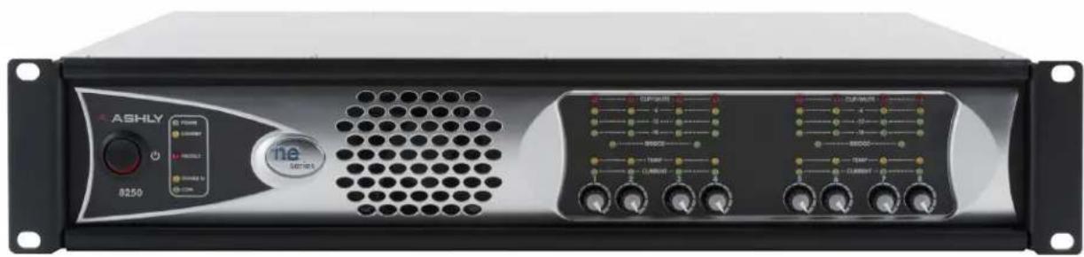
Front view of an ASHLY audio amplifier rack with visible ports, knobs, and a central grille (no readable text or symbols beyond branding)ne8250, ne8250.25, ne8250.70, ne8250.10
natural_image
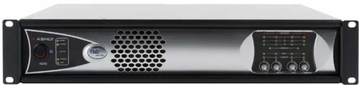
Front view of an ASHLY industrial power supply unit (no visible text or symbols on the device body)ne4250, ne4250.25, ne4250.70, ne4250.10
ASHLY AUDIO INC.
847 Holt Road Webster, NY 14580-9103 Phone: (585) 872-0010
Toll-Free: (800) 828-6308 Fax: (585) 872-0739 www.ashly.com
© 2016 by Ashly Audio Corporation. All rights reserved worldwide.
All Trademarks referred to herein are the property of their respective owners.
The lightning flash with arrowhead symbol, within an equilateral triangle, is intended to alert the user to the presence of uninsulated "dangerous voltage" within the product's enclosure that may be of sufficient magnitude to constitute a risk of electric shock to persons. The exclamation point within an equilateral triangle is intended to alert the user to the presence of important operating and maintenance instructions in the literature accompanying the device.
This device complies with part 15 of the FCC Rules. Operation is subject to the following two conditions:
- This device may not cause harmful interference
- This device must accept any interference received, including interference that may cause undesired operation
Note: This equipment has been tested and found to comply with the limits for a Class B digital device, pursuant to part 15 of the FCC Rules. These limits are designed to provide reasonable protection against harmful interference in both a commercial and residential installation. This equipment generates, uses and can radiate radio frequency energy and, if not installed and used in accordance with the instructions, may cause harmful interference to radio communications. However, there is no guarantee that interference will not occur in a particular installation. If this equipment does cause harmful interference to radio or television reception, which can be determined by turning the equipment off and on, the user is encouraged to try to correct the interference by one or more of the following measures:
- Reorient or relocate the receiving antenna.
- Increase the separation between the equipment and receiver.
- Connect the equipment into an outlet on a circuit different from that to which the receiver is connected.
- Consult the dealer or an experienced radio/TV technician for help..
- Increase the separation between the equipment and receiver. - Connect the equipment into an outlet on a circuit different from that to which the receiver is connected. - Consult the dealer or an experienced radio/TV technician for help..
Table Of Contents
1 INTRODUCTION 4
2 UNPACKING 4
3 THE NE MULTICHANNEL AMP SERIES 5
Overview 5
Protection....5
Physical Description....6
Front Panel Features 6
Rear Panel Features....7
Installation Requirements....7
Constant Voltage Models and High Pass Filters 7
4 REMOTE CONTROL 8
On/Off Remote Standby 8
Preset Recall....8
WR-1 Remote Level Control 9
WR-2 Remote Preset Recall Switch 9
WR-1.5 Remote Level Control and Preset Switch ..... 9
RD-8C and RW-8C Remote Fader Control 10
WR-5 Remote Programmable Button Control. 10
neWR-5 Networked Remote Programmable Button Control ..... 11
FR-8 and FR-16 Networked Programmable Fader Control ..... 11
Ashly Remote App for iPad ^® 11
5 Protea ^ne SOFTWARE 12
Overview 12
Amplifier Control Surface 12
The DSP Window....13
6 SPECIFICATIONS/BLOCK DIAGRAM 14-16
7 WARRANTY 17
WARNING:
THIS APPARATUS MUST BE EARTHED
1. INTRODUCTION
Thank you for your purchase of this NE (network enabled) multi channel power amplifier. NE power amplifiers combine lightweight, state of the art, high efficiency switching technology with integrated Ethernet control, and offer optional factory installed expansion cards to provide comprehensive internal DSP processing, AES/EBU input, and networked digital audio input. Please read the entire manual to fully understand the features and capabilities of this product.
About Ashly
Ashly Audio was founded in 1974 by a group of recording engineers, concert sound professionals, and electronics designers. The first products were elaborate custom consoles for friends and associates, but business quickly spread to new clients and the business grew. The philosophy we established from the very beginning holds true today: to offer only the highest quality audio tools at an affordable cost to the professional user – ensuring reliability and long life. Many years later, Ashly remains committed to these principles.
Ashly's exclusive Five Year, Worry- Free Warranty remains one of the most liberal policies available on any commercial- grade product. The warranty covers every product with the Ashly brand name, and is offered at no extra cost.
FCC Compliance
This device complies with part 15 of the FCC Rules for Class B operation, subject to the following two conditions:
- This device may not cause harmful interference
- This device must accept any interference received, including interference that may cause undesired operation.
2. UNPACKING
As a part of our system of quality control, every Ashly product is carefully inspected before leaving the factory to ensure flawless appearance. After unpacking, please inspect for any physical damage. Save the shipping carton and all packing materials, as they were carefully designed to reduce to minimum the possibility of transportation damage should the unit again require packing and shipping. In the event that damage has occurred, immediately notify your dealer so that a written claim to cover the damages can be initiated.
The right to any claim against a public carrier can be forfeited if the carrier is not notified promptly and if the shipping carton and packing materials are not available for inspection by the carrier. Save all packing materials until the claim has been settled.
3. THE NE MULTICHANNEL AMP SERIES
Models:
ne4250 - Four Channels, Low-Z, 250W per channel into 4 ohms
ne8250 - Eight Channels, Low-Z, 250W per channel into 4 ohms
ne4250.70 - Four Channels, 70 volt output, 250W per channel (must be ordered as 70V)
ne8250.70 - Eight Channels, 70 volt output, 250W per channel (must be ordered as 70V)
ne4250.25 - Four Channels, 25 volt output, 250W per channel (must be ordered as 25V)
ne8250.25 - Eight Channels, 25 volt output, 250W per channel (must be ordered as 25V)
ne4250.10 - Four Channels, 100 volt output, 250W per channel (must be ordered as 100V)
ne8250.10 - Eight Channels, 100 volt output, 250W per channel (must be ordered as 100V)
The basic NE multichannel amplifiers come in either four channel or eight channel configurations with Euroblock input and output connectors. Standard features on all models include balanced inputs, bridge mono mode, and Ethernet control using Protea ^ne software. Remote control functions include standby, contact closure preset recall, and DC level control. Programmable remotes for NE amplifiers with DSP include Ashly's WR-5 or neWR-5 button controllers, RD-8C or FR-8/16 fader controllers, third party RS-232 control, or Ashly Remote app for iPad ^® .
Factory Installed Options
Factory installed hardware options for NE multichannel power amplifiers include the following:
1) Internal DSP - With Protea DSP installed, each input channel benefits from pluggable DSP blocks for dynamics control, gain functions, graphic and/or parametric EQ, Hi-pass/Lo-pass filters, time delay, metering, and test signal generator. A mixer section with assignable routing allows any input to drive any or all amplifier outputs. Output channels have the same DSP functions as inputs, with the addition of automated crossover setup and FIR filter capability. Both inputs and outputs can copy/paste their settings to other channels, or can link with one or more other channels to track their settings.
Presets store and retrieve parameters of an entire amplifier control surface and DSP settings. In addition, Sub Presets allow for a collection of individual DSP parameters within and across multiple channels of an amplifier to be stored and recalled as a set, affecting only those parameters and channels which have been tagged. Up to 35 presets/subpresets can be stored within the amplifier and can be recalled in real time from a computer, by a programmable remote control, or by on-board contact closure switch connections on the back panel.
2) AES3 Input - With a four or eight channel AES3 option installed, AES3 outputs can plug directly into the amplifier. Using AES3, 2 channels of digital audio are sent over a single mic cable, maintaining a completely digital signal path until just before the power amplification stage. 48kHz & 96kHz data rates are supported. AES3 can be installed with or without DSP.
3) Network Audio - Dante ^® or CobraNet ^® network audio modules can be factory installed, with or without installed DSP. Note that amplifiers without DSP must have a factory installed OPDAC4 module to use network audio.
Dante ^® , created by Audinate, is an Ethernet based digital AV network technology that uses existing 100MB or 1GB network infrastructure for delivery of high performance, high channel count audio signals. Ashly products with network audio capability can be integrated into a Dante ^™ digital audio system by purchasing our OPTDante module as a factory installed option, and controlled using Protea ^ne software.
CobraNet ^® is a technology developed and supported by Cirrus Logic (www.cirrus.com). It is a combination of software, hardware and network protocol which allows distribution of multiple channels of real-time, high quality digital audio over a standard Ethernet Network. For detailed information about CobraNet or its implementation or installation please visit www.cobranet.info.
Protection
NE multichannel amplifiers use the following protection schemes:
Over Current Protection - Is controlled in the output stage.
Thermal Protection - The amplifier senses output device temperature and adjusts a two-speed fan to keep the operating temperature within acceptable limits. If device temperatures exceed that limit, the input to that channel is first reduced, and as a last resort the power supply will be switched off while the fan continues to run.
Mains Protections – Protection within the power supply includes: Inrush Current Limitation during power up, Mains Over Voltage Detection, and internal Mains Fuse Protection. To protect the Mains fuse against AC overcurrent due to excessive audio output current, there is also a protection scheme indicated on the amplifier front panel and software control surface which reduces audio output level until the overcurrent condition is no longer present.
Physical Description
Each model in the NE Multichannel series is 2RU. The model number is indicated in the lower left corner of the front panel.
Amplifier Front Panel
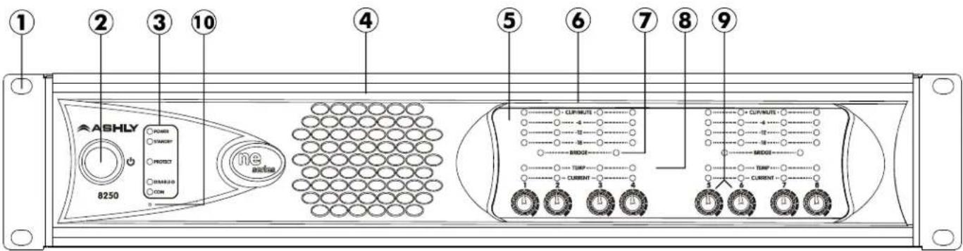
- Mounting Holes – For rack mounting
- Power Switch - Switches the unit on or off. Note: The power switch can be disabled from software.
- Status LEDs – Indicates status of Power, Standby, Protect, Power Switch Disable, and Ethernet activity.
- Air Vents - Cool air enters the sides and is blown out the front.
- Channel Controls – Channel control area.
- Signal LEDs – The lowest LED will begin to light when the output voltage is -18dBu below rated output. The Clip LEDs will begin to flash when output voltage is 1/2 volt below the rated output power supply voltage.
- Bridge - This LED indicates that the channel pair is selected to BRIDGE mode from the back panel switch, and that only the odd input channel level control is active.
- Temp and Current LEDs - The Temp LED indicates an excessively high operating temperature and that countermeasures are being used to cool the amplifier. The Current LED confirms that the amplifier output is delivered to a speaker load.
-
Channel Attenuators - These control the input signal level to the amplifier. They can be disabled from software.
-
Factory Reset – To reset all internal configurations (including passwords) back to their original factory settings, press and hold this recessed front panel momentary switch during power up until all channel LEDs are lit. Upon reset completion, the LEDs will turn off and the amp will resume normal operating mode.
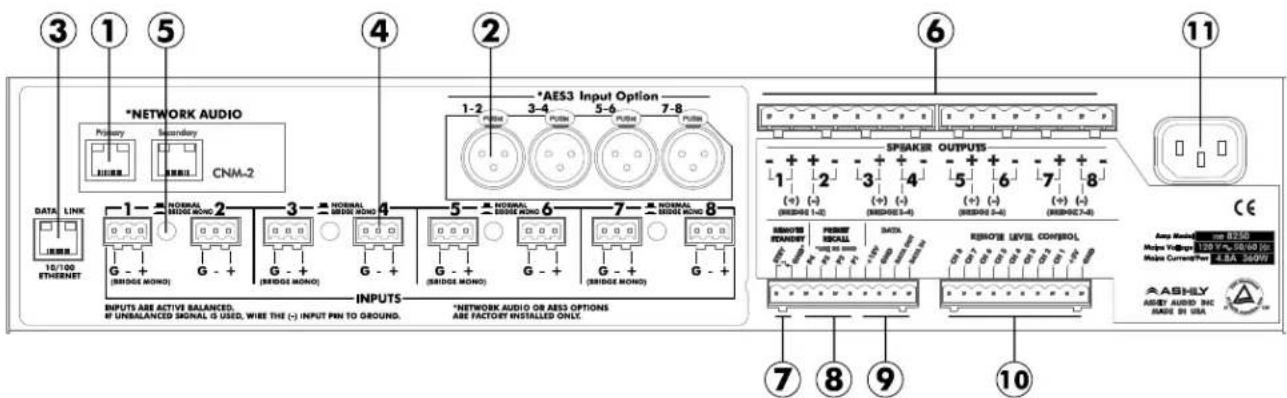
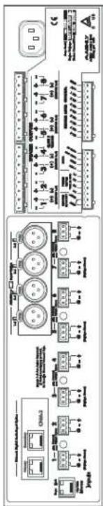
Amplifier Rear Panel (illustration on next page)
-
Optional Network Audio – This factory option allows connection to a Dante or Cobranet audio network.
-
Optional AES3 - This slot is for factory installation of an AES3 digital audio input module.
-
Ethernet Port - This RJ45 jack is for connecting to an Ethernet network for software control.
-
Input Connector - This is used for a three wire (G, +, -) balanced input on Euroblock connectors.
-
Normal/Bridge Switch - This switches the channel pair to Bridge Mode.
-
Euroblock Speaker Connectors - Used to connect speakers to individual output channels or in bridged mode.
-
Remote Standby - These two contact closure pins are wired to a switch to remotely place the amp in standby.
-
Preset Recall - These four pins (and GND) can be wired to remote switches to recall up to four amplifier presets.
Amplifier Rear Panel (continued)
text_image
③ ① ⑤ ④ ② *NETWORK AUDIO Primary Secondary CNM-2 DATA LINK 10/100 ETHERNET 1 G - + (NBRIDGE MONO) NORMAL RESIDE MONO G - + (BRIDGE MONO) INPUTS INPUTS ARE ACTIVE BALANCED. IF UNBALANCED SIGNAL IS USED, WIRE THE (+) INPUT PIN TO GROUND. N/AES3 Input Option 1-2 PULSE 3-4 PULSE 5-6 PULSE 7-8 NORMAL RESIDE MONO G - + (SRIDGE MONO) G - + (BRIDGE MONO) INPUTS *NETWORK AUDIO OR AES3 OPTIONS ARE FACTORY INSTALLED ONLY. ⑥ ⑦ ⑧ ⑨ ⑩ ⑪ ⑬ ⑭ ⑮ ⑯ ⑰ ⑪ ⑫ ⑬ ⑭ ⑮ ⑯ ⑰ ⑪ ⑬ ⑭ ⑮ ⑯ ⑰ ⑪ ⑬ ⑭ ⑮ ⑯ ⑰ ⑪ ⑬ ⑭ ⑮ ⑯ ⑰ ⑪ ⑬ ⑭ ⑮ ⑯ ⑰ ⑪ ⑬ ⑭ ⑮ ⑯ CE Speaker OUTPUTS 1 2 3 4 5 6 7 8 (+) (-) (-) (-) (-) (-) (-) (-) (-) (-) (-) (-) (-) (-) (-) (-) (-) (-) (-) (-) (-) (-) (-) (-) (-) (-) (-) (-) (-) (-) (-) (-) (-) (-) (-) (-) (-) (-) (-) (-) (-) (-) (-) (-) (-) (-) (-) (-) (-) (-) (-) (-) REMOTE RECOVERY PEEKRET RECALL DATA REMOTE LEVEL CONTROL 128.9% 30.0% (E) Maxus Current/Per 2.8A 300Hz ASHLY ASSET AUDIO INC MADS BY USA-
Data - These four pins can be wired to remote serial data controllers such as the Ashly WR-5 or RD-8C.
-
Remote Level Control - These pins are wired to potentiometers such as the WR-1 for level control of individual channels
-
AC Inlet - Used for the detachable AC cord supplied with the amplifier.
WARNING: Do not remove or lift the mains connector ground pin.
Installation
Before connecting to mains power, make sure that the switches and wiring are all set to the configuration needed for your particular application. Failure to do so could result in damage to the unit or to other components in your system.
CAUTION: Before mounting or connecting the amplifier, always disconnect it from AC. Use four screws with lockwashers when mounting the amplifier to the front rack rails. Rear support is also recommended, especially for mobile or touring use. To reduce the risk of fire or electric shock, do not expose this apparatus to rain or moisture.
Requirements
NE multichannel amplifiers have specific physical, electrical and signal requirements for proper operation. These requirements will vary depending on your specific application, setup, and settings on the amplifier. When setting up and testing your system, please take special care to double check all connections and settings. Refer to the specifications section of this manual for specific input, output and other figures.
Constant Voltage Models (25V, 70V, and 100V) and High Pass Filters
Amplifiers that are factory configured as constant voltage models (25V, 70V, or 100V) come standard with High Pass Filter (HPF) hardware installed, allowing for software selectable 80Hz or 400Hz filters on each channel. High pass filters prevent low frequency energy from saturating the iron core of low cost speaker tap transformers typically used in distributed constant voltage systems. Available filters are 80Hz @12dB/oct, 400Hz @ 6dB/oct, and OFF. The 400Hz setting is commonly used in paging systems with horn speakers. Note that with just the standard HPF hardware installed, DSP, network audio, or AES3 input are unavailable.
NE amplifiers shipped with AES3 or network audio, but without DSP, also come with an Ashly OpDAC A/D converter card installed. This OpDAC converter card offers the same software controlled HPF options as the standard amp.
Note: Constant voltage amplifiers that ship with Protea DSP do not have the standard 80Hz/400Hz HPF circuitry installed, and as such must have High Pass filters manually set in the software DSP section.
4. REMOTE AMPLIFIER CONTROL
ON/OFF/Remote Standby
The NE multichannel amplifiers have three possible states, OFF, ON, and STANDBY, each with a status LED on the front panel. Control for these three states is managed by the following:
1) Power Switch - When the power switch is turned off the amplifier is completely off, UNLESS the power switch has been disabled from software, in which case the power switch on the amplifier has no effect at all. If the power switch has been disabled, the front panel DISABLE LED will be lit. Even if the AC power is removed, the amplifier's internal memory will retain the
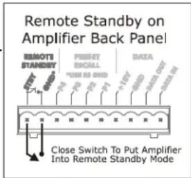
2) Remote Standby Contact Closure - When these two pins are wired to a switch and connected closed, the amp will go into standby mode, whereby the amp is active but in a reduced power state. For remote standby to work, the power switch must be turned on or on but disabled in software.
text_image
Remote Standby on Amplifier Back Panel REMOTE STANDBY 1st 2nd 3rd 4th 5th 6th 7th 8th 9th 10th 11th 12th 13th 14th 15th 16th 17th 18th 19th 20th 21st 22nd 23rd 24th 25th 26th 27th 28th 29th 30th Close Switch To Put Amplifier Into Remote Standby Mode3) Software On/Standby - On/standby in software functions the same as the remote standby contact closure on the back panel. Clicking on STANDBY places the amp into standby mode. Software on/standby does not override the hardware Remote Standby, they both remain active.
4) Software Power Switch Enable/Disable - This feature disables the front panel power switch. If the power switch is disabled from software, the front panel DISABLE LED is lit. The power switch remains disabled until enabled again from software, even after the amp is unplugged from AC.
Preset Recall
The preset recall connections on the back panel allow different presets to be loaded from amplifier memory when one of the contacts is closed to the provided ground pin. Device presets are configured from software and can include gain settings, mute status, polarity, and DSP functions if the amp has DSP installed.
The NE amplifier stores up to 35 internal device presets. A device preset stores the most commonly used control data for that amplifier. A device preset (saved to amplifier) differs from a computer preset file in that a computer preset file stores all information associated with the amplifier and its software settings, while the device preset only stores the most commonly used and relevant audio settings. Changes to an individual preset can be saved to the amplifier in software using
Loading a preset can be done using software, using preset recall contact closure connections on the back panel, using an Ashly programmable remote button controller, or using the Ashly Remote iPad® app. Contact closure pins P1 through P4 load device presets 1-4 from the amplifier memory.
Caution: A new preset may have dramatically different settings capable of damaging sound system components. Be careful not to recall the wrong preset while the system is on.
Data Control
The data euroblock on the back of the amplifier is used for connecting an Ashly WR-5 programmable zone controller or RD-8C remote level controller. The data interface provides data and phantom power for these devices using four conductor bell wire.
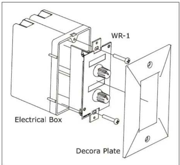
WR-1 Remote Level Control - The WR-1 is a dual potentiometer remote volume control designed to mount in a standard single US electrical wall box, and is wired to the amplifier back panel Euroblock connector labeled "Remote Level Control" using four conductor wire. Installed DSP is not required for WR-1 remote level control. If wiring a custom potentiometer assembly other than the WR-1, connect +5V from the Remote Level Control Euroblock connector to the potentiometer's CW pin, GND to the CCW pin, and the channel under control to the wiper. Do not connect the WR-1 remote level control ground to any other external grounds.
text_image
WR-1 Electrical Box Decora Plate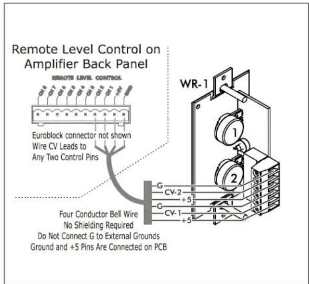
text_image
Remote Level Control on Amplifier Back Panel Euroblock connector not shown Wire CV Leads to Any Two Control Pins Four Conductor Bell Wire No Shielding Required Do Not Connect G to External Grounds Ground and +5 Pins Are Connected on PCB WR-1 G CV-2 +5 G CV-1 +5WR-1 Remote Level Control
WR-2 Remote Preset Recall Switches - The WR-2 (shown at right) allows selection of one of four presets via interlocking pushbutton switches. Each pushbutton switch can be connected to a Preset Recall Pin on the back panel of the amplifier. The terminal numbers correspond to the first 4 device presets stored in the amplifier. Pressing any button will select the corresponding preset. Windows are provided by each switch for a user-generated label.

text_image
LEVEL 2 3 1 4 ASHLY WR-1.5 WR-1.5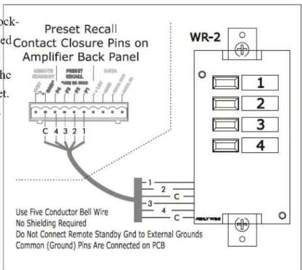
text_image
Preset Recall Contact Closure Pins on Amplifier Back Panel WR-2 1 2 3 4 Use Five Conductor Bell Wire No Shielding Required Do Not Connect Remote Standby Grid to External Grounds Common (Ground) Pins Are Connected on PCBWR-2 Remote Preset Recall Switches
WR-1.5 Remote Level Control and Preset Recall Switch The WR-1.5 (shown at left) combines one potentiometer for remote level control with a four position rotary switch for preset recall.
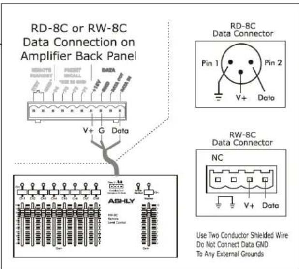
RD-8C or RW-8C Remote Level Control - The RD-8C and RW-8C are remote level controllers which are connected to the amplifier's Data Port, and are phantom powered from the amplifier. They can only be used in NE amplifiers which have DSP installed, and are used in conjunction with the "Remote Gain" pluggable DSP tool placed in an input or output in software.
Maximum cable length is 1000 ft using #24 gauge twisted pair. The RD-8C is a desktop controller, while the RW-8C is electronically the same but mounts as a wall plate using a standard North American 4-gang electrical box and connects using a Euroblock.. There are eight channels and a master, each with a fader control and an on/off button. Note: Only one RD-8C can be used per amplifier, and use of an RD-8C will exclude the use of the data port for a WR-5. One or the other remote control device may be connected, but not both
text_image
RD-8C or RW-8C Data Connection on Amplifier Back Panel RD-8C Data Connector Pin 1 Pin 2 V+ Data V+ G Data RW-8C Data Connector NC Use Two Conductor Shielded Wire Do Not Connect Data GND To Any External GroundsRD-8C or RW-8C Remote Level Control
WR-5 Programmable Button Con-
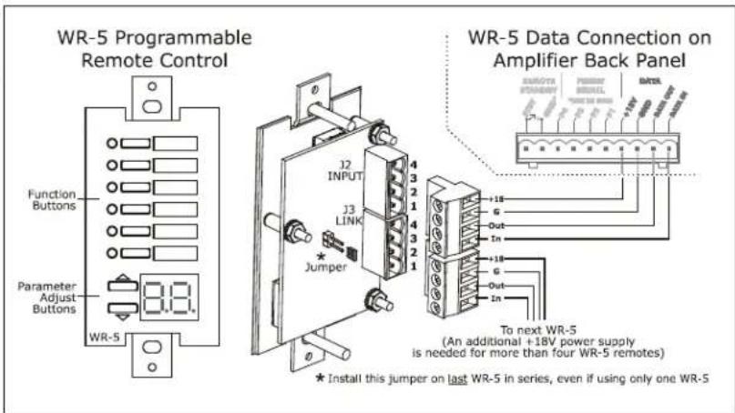
troller - The WR-5 is a programmable button remote control which mounts into a standard US electrical wall box and connects to an amplifier data port using four conductor wire. Maximum cable length is 1000 ft using #24 gauge twisted pair. A decora cover plate (not included) can be purchased at hardware stores to cover the WR-5 electrical box and satisfy the aesthetic needs of the installation. The WR-5 is phantom powered from the amplifier. Up to four different WR-5 remotes can be phantom powered from one amplifier, and more can be added by purchasing an Ashly RPS-18 remote power supply.
text_image
WR-5 Programmable Remote Control Function Buttons Parameter Adjust Buttons WR-5 J2 INPUT J3 LINK Jumper WR-5 Data Connection on Amplifier Back Panel To next WR-5 (An additional +18V power supply is needed for more than four WR-5 remotes) * Install this jumper on last WR-5 in series, even if using only one WR-5WR-5 Programmable Button Controller
WR-5 buttons are programmed from software, after the WR-5 is wired to an amplifier and assigned a unique ID number in the WR-5 device window associated with that amplifier in software. Each WR-5 button has a status LED. Standard control functions include preset recall/scroll and mute, and in amplifiers with DSP installed the functions also include gain control, zone source selection, individual channel and matrix point level control. Note: To use the WR-5 as a remote level control, a (ne)WR-5 Remote Gain tool must be placed in one of the DSP processing blocks of the channels(s) to be controlled. A windowed mylar pocket is available to insert custom button labels. A WR-5 label template is available on the Ashly web site.
INA-1 Inline RS-232 Adapter (not shown) - The amplifier Data Port uses a proprietary serial communications protocol which can be converted to RS-232 by purchasing the Ashly INA-1 RS-232 adapter. This allows the use of custom designed third party RS-232 controllers.
text_image
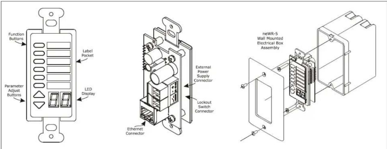
Function Buttons Parameter Adjust Buttons Label Pocket LED Display External Power Supply Connector Lockout Switch Connector Ethernet Connector neWR-5 Wall Mounted Electrical Box AssemblyneWR-5 Networked Programmable Button Controller
neWR-5 Networked Programmable Button Controller - The neWR-5 remote control is a networked version of the WR-5, using Ethernet instead of the data port to communicate with the amplifier. Connecting and powering the neWR-5 is done using Cat-5 Ethernet cable and a Class 1 IEEE 802.3af Power over Ethernet (PoE) switch, hub, or in-line PoE injector. If PoE is unavailable, the Ashly RPS-18 (sold separately) is a 15-48VDC power supply capable of at least 2 watts per neWR-5 and can be hard wired to the back of the neWR-5. PoE current draw is 38mA @48VDC and 80mA@15VDC. A decora cover plate (not included) can be purchased at hardware stores to cover the neWR-5 electrical box and satisfy the aesthetic needs of the installation.
The neWR-5 appears in the software device menu tree and must be assigned within it's device window to a specific amplifier. The neWR-5 has six programmable function buttons which can light up green, red, or amber to display status. Further information on LED status is found in the neWR-5 owner's manual, available on the Ashly website. To the right of the function buttons is a pocket in the mylar overlay for a printed function label to be inserted, also available as a template on the website. The two other buttons are used to adjust function parameters such as gain or preset number, and are indicated by the LED display. Without DSP installed in the amplifier, neWR-5 functions are limited to preset recall and mute. Note: To use the neWR-5 as a remote level control, a (ne)WR-5 Remote Gain tool must be placed in one of the DSP processing blocks of the channels(s).
There is also a hard-wired Lock-Out feature on the neWR-5, where the closing of a switch wired to the lockout Euroblock renders all buttons inactive.
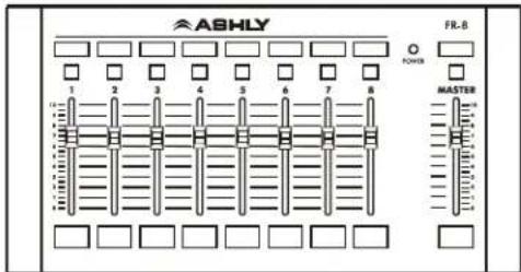
FR-8 and FR-16 Networked Fader Controller - The FR-8 (shown at right) and FR-16 are Ethernet based remote fader control units, with the ability to assign each fader control of one or more input or output DSP gain stages or level control for a DSP matrix mixer point. The button LEDs for each fader are normally used to indicate as- signable signal level/clip or mute
text_image
ASHLY FR-B 1 2 3 4 5 6 7 8 POWER MASTERFR-8 Networked Fader Controller
text_image
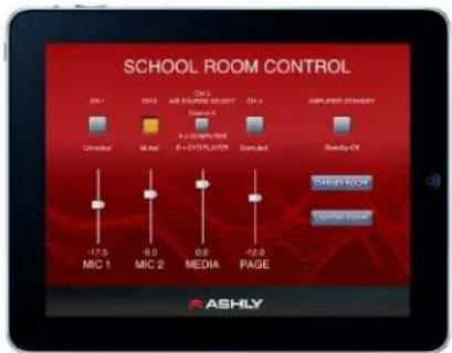
SCHOOL ROOM CONTROL ON 1 ON 2 AIR EQUIPMENT CONTROL ON 3 AIR CONDITION CONTROL Standard Unmarked X-Alt X-LEARNING R = 510 PLAT/ON Standard Balance OFF -17.5 -0.0 0.0 MIC 1 MIC 2 MEDIA PAGE ASHLYAshly Remote App for iPad ^®
status, but can alternately select A/B signal source for that fader. The FR remotes can be wall mounted to electrical box, panel mounted, or freestanding, and have a back panel contact closure for full front panel lockout. See further details in the FR-8/16 owner's manual on the Ashly website.
Ashly Remote App for iPad ^® - A custom and secure touch-screen control surface for the iPad ^® can be designed using the
5. PROTEA ^ne SOFTWARE
Protea ^re software offers a comprehensive suite of tools for controlling Ashly NE multichannel amplifiers. The standard amplifiers allow for Ethernet control and monitoring of power functions, mute, and preset control. With the DSP option installed, software control and monitoring of audio functions can be custom configured on a per channel basis, as well as through linked channels. More in depth discussion of software features can be found in the Protea ^re software online help.
The base amplifier interface includes a main control surface, password protected security functions, and network property management. Link Group Configuration and Power On Delay* can be set up under the Device Options menu tab. In addition, provisions for implementing DSP functions, AES/EBU Inputs, and network audio inputs are available, presuming the necessary hardware options have been installed in the amplifier. Protec software will auto-detect any installed hardware options and display the resulting menu items once it recognizes the amplifier on the network.
*Note - Power On Delay does not work when standby mode is activated via contact closure.
Link Group Configuration - Linking allows the controls for multiple DSP function blocks to track each other. For example, if two different graphic equalizer blocks are assigned to a link group, any change made to a control within either of the equalizers will result in an identical change to the other. Blocks may be linked across channels.
Each device will support up to 16 link groups. DSP function blocks can be individually assigned to these link groups. Once assigned to a group, all similar functions within that group will track parameter changes. More than one function type may be assigned to a group. Each link group can be assigned a name by the user, and can also be assigned a color for easy identification. For further details about linking, see the software online help.
Preset Options - The preset options menu allows amplifier setups to be saved to or recalled from an amplifier or a computer. File presets are the complete amplifier and software settings, whereas device presets are limited to commonly used functions.
Sub Presets - Sub Presets are user defined groups of DSP functions within one channel or across multiple channels. Sub Presets allow the user to instantly recall a pre-determined set of DSP parameters to quickly address changing environmental conditions, without the risk of making undesirable or irrecoverable system changes.
The Amplifier Control Surface Tab
The control surface tab is the main software interface for the amplifier. Key features of this window include:
1) Channel and Offset Link Group Faders - The main level control provides up to 40dB of analog input attenuation. More than 40dB of cumulative attenuation causes the channel to mute. If a channel has been assigned to an offset link group, a colored triangular marker appears on the left side of the fader graticule for secondary level control of all channels in that group. The main level control faders can not be linked to a group.
2) Mute button - This mutes the input channel
3) Polarity button - This inverts the phase of the input channel
4) Offset link group - Up to 16 groups are available for the purpose of linking similar function parameters across multiple channels. In addition to the control surface secondary level control (not the main fader), most DSP functions have a link group check box in their work window to assign a specific parameter to one of the eight link groups if desired. Link groups can be renamed by clicking on any group name and entering the new name then pressing
5) Attenuators - These two dials indicate the physical position of hardware controls on either the amp front panel or remote DC level control (if present). Note that these will display the position of attenuators even when they are disabled by software.
6) Total Attenuation - This indicates the total amount of attenuation being applied to the channel. This is the sum of the following attenuators: main fader, offset link group attenuation, front panel and remote attenuators.
7) Meters - Input and Output meters display the real time activity per channel, in dB below rated output. Also, the amplifier's operating temperature and output current are shown. Output current shows that the amplifier channel is actually delivering output to a connected speaker load.
The Amplifier DSP Tab
If the amplifier has DSP installed, the DSP tab automatically appears. The DSP tab includes an input side and an output side, with a cross linking matrix mixer in between. Key features of the DSP window include:
Input Channel Number - Right click on this to bring up Clear, Copy/Paste, Link, and Sub Preset for that input channel.
Input Channel Name - The user can name each input channel.
Input Mute Button - Mutes the input.
Pluggable DSP Tools - Six blocks are available on both inputs and outputs for custom configuration of pluggable DSP processing blocks. Total DSP usage for the four input and output channel groups is indicated as a percentage at the bottom of each input section in the DSP tab. Increasing the number and complexity of applied DSP tools increases the DSP usage. Note: The total DSP usage per group of four channels is limited, and cannot exceed 100%. Available DSP tools include:
1) Dynamics controls - Brick Wall Limiter, Compressor, Autoleveler, Ducker, Noise Gate
2) Gain functions - Gain, Gain with VCA, Remote Gain, (ne)WR-5 Remote Gain
3) Equalization - 31 band Graphic Equalizer, 10/6/4/2 Band Parametric Equalizers, FIR filter (outputs only)
4) Crossover functions - Four Way, Three Way, and Two Way Crossovers are available on outputs only.
HPF and LPF filters are available on both inputs and outputs.
5) Delay - Speaker Delay at 48kHz sampling rate is 21mS, and Delay is 682mS. At 96kHz, 10.6mS and 341ms.
6) Metering - -60dBu to +20dBu display
7) Signal Generator - Pink noise, White Noise, Sine Wave from 20Hz to 12kHz.
Extensive online help information is available for all DSP blocks within the software. From within any DSP tool, simply press
Input/Output Matrix Router - Any input can be routed to any or all outputs. Click and drag from the input to output to assign routing. For faster routing of a single input or output to multiple channels, highlight its node and then press Ctrl+Click over the desired nodes to connect to. To delete a route or clear the matrix, right click on the routing line or node. Also, right click anywhere in the matrix area to bring up a menu of common routing choices.
Output Mute Button - Mutes the output.
Output Channel Name - The user can name each output channel.
Output Channel Number - Right click on this to bring up Clear, Copy, Link, and Sub Preset functions for that output.
6. SPECIFICATIONS
General Power Amplifier Specifications
0dBu = 0.775V rms
Base Model 4250 8250
120VAC 230VAC 120VAC 230VAC
Continuous Average Power Output Per Channel
Low Z models, Stereo Mode, all channels driven
Low Z models, Bridge Mode, all channels driven
Line Current Draw (all channels driven)
Standby mode....190mA 95mA 290mA 145mA
Idle (no signal)....540mA 270mA 565mA 283mA
Typical (1/8 power pink noise)....2.85A 1.43A 5.00A 2.50A
Maximum (1/3 power sine wave)....6.00A 3.00A 11.0A 5.50A
Thermal Dissipation (BTU/hr, all channels driven)
Standby mode, 46.7 46.7 63.8 63.8
Idle (no signal)....123 123 187 187
Typ (1/8 power pink noise)....341 341 700 700
Max (1/3 power sine wave) 378 378 775 775
Signal to Noise (20Hz-20KHz, unweighted) >105dB
Distortion (SMPTE, typical) - 8 ohm load, 10dB below rated power: ....<0.5%
Distortion (THD-N, typical) - 8 ohm load, 10dB below rated power, 20Hz-20kHz:....<0.5%
Frequency Response 20Hz-20kHz, +/-1dB
Damping Factor (8 ohm load, <1kHz) >250
Input Impedance....20K Ohm, balanced
Maximum Input Level +21dB
Cooling.... temperature controlled fan, cool air is drawn in from the sides and blown out the front
Control Network.....Standard 100MB Ethernet
Front Panel Indicators...per channel: Clip/Mute, -6dB, -12dB, -18dB, Temp, Current, Bridge (per pair)
overall: Power, Standby, Protect, Power Switch Disable, Comm
Control Surface and Amp LEDs: Level meters are in dB below rated output
Attenuators....per channel: front panel, software, offset link group, and remote
Input/Remote Connectors. Euroblock (5.08mm)
Output Connectors..... Euroblock (7.62mm)
Amplifier Protection....inrush current limitation, temperature monitoring, output over-current protection, mains fuses
Power Requirements . . . 120VAC or 240VAC (factory set) ±10%, 50/60Hz
Power Cable Connector. . 15A Edison
Unit Dimensions....19"W x 3.5"H x 16.84"D (483 x 89 x 428mm)
Unit Weight . . . . . . . . . . ne4250: 23 lbs (10.4kg), ne8250: 24.7 lbs (11.2kg)
Shipping Weight ..... ne4250: 29.1 lbs (13.2kg), ne8250: 30.8 lbs (13.9kg)
Environmental: .... 40°-120°F, (4°-49°C), noncondensing
Safety/Compliance....cTUVus, FCC Class B, CE, RoHS
DSP Specifications
Input....Active Balanced, 10 kohms
Max Input Level....+21 dBu
Dynamics
Brick Wall Limiter
Threshold....-20dBu to +20dBu
Ratio......infinite
Attack....0.2ms/dB to 50 ms/dB
Release....5ms/dB to 1000ms/dB
Compressor
Threshold....-20dBu to +20dBu
Ratio....1.2:1 to infinite
Attack....0.2 to 50ms
Release....5ms/dB to 1000ms/dB
Detector....Peak/Average
Autoleveler
Target Level....-40dBu to +20dBu
Action....gentle, normal, aggressive, user defined
Maximum Gain....0dB to +15dB
Ratio....1.2:1 to 10:1
Threshold Below Target .....-30dB to 0dB
Gain Increase Rate.....5ms/dB to 1000ms/dB
Hold Time....0-6 sec
Ducker
Ducking Type high/low priority, trigger, filibuster,
ducked program
Trigger Threshold ..... -80dBu to +20 dBu
Ducking Release....5ms/dB to 1000ms/dB
Ducking Depth....0dB to -30dB
Gate
Threshold....-80dBu to +20dBu
Range....off, 100dB to 0dB
Attack....0.2ms/dB to 50 ms/dB
Release....5ms/dB to 1000ms/dB
Gain
Gain....off,-50dB to +12dB
Gain w/VCA....off, -50dB to +12dB
WR-5 Remote Gain .... .off, -50dB to +12dB
Equalization
FIR Filter (Output only, 48kHz only, 2-384 Taps)
File types ....*.csv, *.fir
31 Band Graphic
Filter Type . . . . . . . . . . . . . . . constant Q or proportional
Bandwidth 0.499oct to 0.25oct
2, 4, 6, or 10 Band Parametric
Filter Types
Parametric:
Frequency.....20-20kHz
Level....-30dB to +15dB
Q Value....0.016oct to 4oct
Hi/Low Shelf 6/12 dB
Frequency.....20Hz-20kHz
Level....-15dB to +15dB
All Pass
Frequency 20Hz-20kHz
Variable Q HP/LP
Frequency.....20Hz-20kHz
Q Value....3.047 to 0.267
Notch/Bandpass
Frequency.....20Hz-20kHz
Q Value....92.436 to 0.267
Crossover
2 Way, 3 Way, 4 Way Crossover
High Pass/Low Pass Filters
Filter Types:
Bessel....12/18/24/48 dB/oct
Butterworth ....12/18/24/48 dB/oct
Linkwitz 12/24/48 dB/oct
Frequency....off, 20Hz-20KHz
Delay
@ 48kHz Sampling Rate
Speaker Delay 0-21ms
Delay 0-682ms
@ 96kHz Sampling Rate
Speaker Delay . . . . . . . . . . . . . 0-10.6ms
Delay 0-341ms
Tools
Audio Meter
Range....-60dBu to +20dBu
Increments ....1dB
Peak Hold Indicator.....yes
Signal Generator....pink noise, white noise, sine wave
Sine Wave Frequency.....20Hz-12kHz
Signal Level....off, -50dBu to +20dBu
Cross Point Mixer
Gain....Off., -50dB to +12dB
0.5dB increments with Mute at -50dB
Linking
All functions can be linked to 1 of 16 link groups
Processors
Input A/D ....24 bit (Burr Brown PCM4204)
Output D/A....24 bit (Burr Brown PCM4104)
DSP Processors ....32-bit floating point (Sharc ADSP-21262)
Sample Rates ....48kHz, 96kHz
Propagation Delay @ 48kHz 1.42 ms
Propagation Delay @ 96kHz 0.71 ms
Four or Eight Channel AES3 Digital Audio Input Option
Type 110 ohm transformer balanced XLR
Sample Rates .....48kHz, 96kHz
Max Cable Length .....100 meters
Network Audio Option
Available Types ....Dante®, CobraNet®
NE Multi-Channel Power Amplifier - Block Diagram
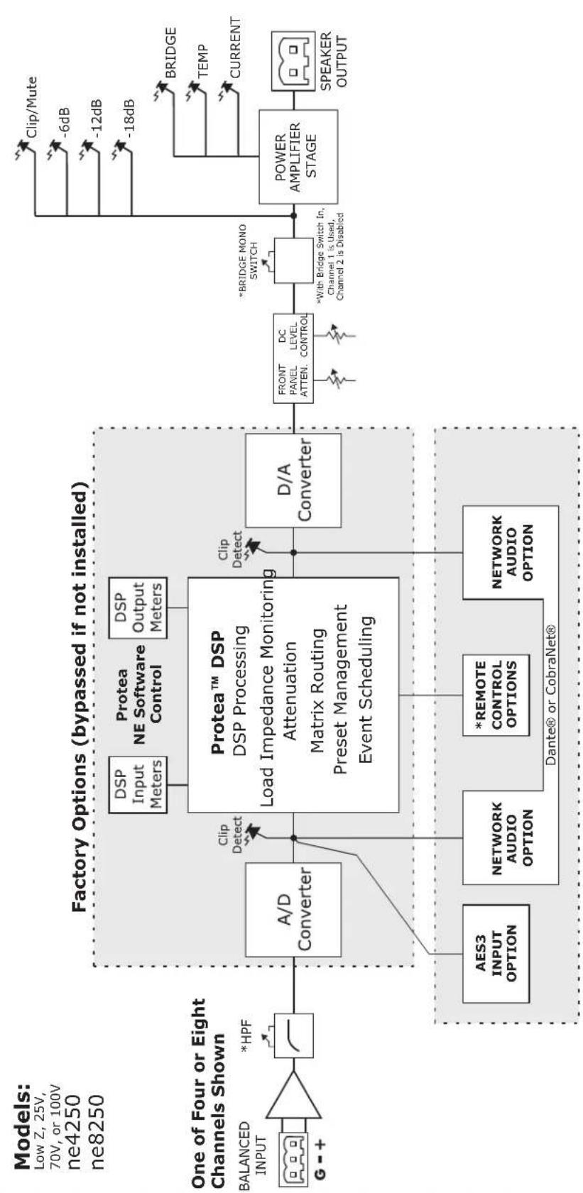
flowchart
graph LR
    A["BALANCED INPUT"] --> B["One of Four or Eight Channels Shown"]
    B --> C["A/D Converter"]
    C --> D["Clip Detect"]
    D --> E["DSP Input Meters"]
    D --> F["DSP Output Meters"]
    E --> G["Protea™ DSP<br>DSP Processing<br>Load Impedance Monitoring<br>Attenuation<br>Matrix Routing<br>Preset Management<br>Event Scheduling"]
    F --> G
    G --> H["D/A Converter"]
    H --> I["FRONT PANEL ATTEN. DC LEVEL CONTROL"]
    I --> J["*BRIDGE MONO SWITCH"]
    J --> K["POWER AMPLIFIER STAGE"]
    K --> L["SPEAKER OUTPUT"]
    C --> M["AES3 INPUT OPTION"]
    C --> N["NETWORK AUDIO OPTION"]
    C --> O["*REMOTE CONTROL OPTIONS"]
    C --> P["NETWORK AUDIO OPTION"]
    J --> Q["BRIDGE"]
    J --> R["TEMP"]
    J --> S["CURRENT"]
    K --> T["Clip/Mute"]
    K --> U["-6dB"]
    K --> V["-12dB"]
    K --> W["-18dB"]
Available Factory Option Configurations:
1) Standard - Without Protea DSP or Network Audio
2) With Protea DSP
3) With Protea DSP and Network Audio or AES3 Input
4) With Network Audio or AES3 Input but Without DSP (factory installed DAC converter required)
*Remote Control Options Vary With Configuration, DSP is Required for Most Programmable Remote Control Functions
text_image
Electrical schematic diagram showing connections between components like capacitors, relays, and power supply lines with labeled terminals.
text_image
AAS-6Y AIR AIR Control AIR Control AIR Control AIR Control AIR Control AIR Control AIR Control AIR Control AIR Control AIR Control AIR Control AIR Control AIR Control AIR Control AIR Control AIR Control AIR Control AIR Control AIR Control AIR Control AIR Control AIR Control AIR Control AIR Control AIR Control AIR Control AIR Control AIR Control AIR Control AIR Control AIR Control AIR Control AIR Control AIR ControlLIMITED WARRANTY (USA ONLY)
(Other countries please contact your respective distributor or dealer.)
For units purchased in the USA, warranty service for this unit shall be provided by ASHLY AUDIO, INC. in accordance with the following warranty statement.
ASHLY AUDIO, INC. warrants to the owner of this product that it will be free from defects in workmanship and materials for a period of FIVE years from the original-date-of-purchase. ASHLY AUDIO INC. will without charge, repair or replace at its discretion, any defective product or component parts upon prepaid delivery of the product to the ASHLY AUDIO, INC. factory service department, accompanied with a proof of original-date-of-purchase in the form of a valid sales receipt. This warranty gives you specific legal rights, and you may also have other rights, which vary from state to state.
EXCLUSIONS: This warranty does not apply in the event of misuse, neglect, or as a result of unauthorized alterations or repairs made to the product. This warranty is void if the serial number is altered, defaced, or removed. ASHLY AUDIO, INC. reserves the right to make changes in design, or make additions to, or improvements upon, this product without any obligation to install the same on products previously manufactured.
Any implied warranties, which may arise under the operation of state law, shall be effective only for FIVE years from the original-date-of-purchase of the product. ASHLY AUDIO, INC. shall be obligated to only correct defects in the product itself. ASHLY AUDIO, INC. is not liable for any damage or injury, which may result from, or be incidental to, or a consequence of, such defects. Some states do not allow limitations on how long an implied warranty lasts, or the exclusion, or limitation of incidental or consequential damages, so the above limitations or exclusions may not apply to you.
OBTAINING WARRANTY SERVICE:
For warranty service in the United States, please follow this procedure:
1) Return the product to ASHLY AUDIO, INC. freight prepaid, with a written statement describing the defect and application that the product is used in. ASHLY AUDIO, INC. will examine the product and perform any necessary service, including replacement of defective parts, at no further cost to you.
2) Ship your product to:
ASHLY AUDIO, INC.
Attention: Service Department
847 Holt Road
Webster, NY 14580-9103
This page intentionally left blank
This page intentionally left blank

ASHLY
ASHLY AUDIO INC. 847 Holt Road Webster, NY 14580
Phone: (585) 872-0010 Fax: (585) 872-0739
Toll Free (800) 828-6308 www.ashly.com
Ashly Audio is a division of Jam Industries, Ltd.
©2016 by Ashly Audio Inc. All rights reserved worldwide.
All features, specifications, and graphical representations are subject to change or improvement without notice.