
XG-P25X - Video projector SHARP - Free user manual and instructions
Find the device manual for free XG-P25X SHARP in PDF.


User questions about XG-P25X SHARP
0 question about this device. Answer the ones you know or ask your own.
Ask a new question about this device
Download the instructions for your Video projector in PDF format for free! Find your manual XG-P25X - SHARP and take your electronic device back in hand. On this page are published all the documents necessary for the use of your device. XG-P25X by SHARP.
USER MANUAL XG-P25X SHARP
text_image
Suppliens, repetsils Suppliens, repetsils Suppliens, repetsils Suppliens, repetsils Suppliens, repetsils Suppliens, repetsils Suppliens, repetsils Suppliens, repetsils Suppliens, repetsils Suppliens, repetsils Suppliens, repetsils Suppliens, repetsils suppliens, repetsils suppliens, repetsils suppliens, repetsils suppliens, repetsils suppliens, repetsils suppliens, repetsils suppliens, repetsils suppliens, repetsils suppliens, repetsils suppliens, repetsils suppliens, repetsils suppilis, repetsils supplis, repetsils supplis, repetsils supplis, repetsils supplis, repetsils supplis, repetsils supplis, repetsils supplis, repetsils supplis, repetsils supplis, repetsils supplis, repetsils supplis, repetsils supplis, repetsils supplis, repedsils supplis, repetsils supplis, repetsils supplis, repetsils supplis, repetsils supplis, repetsils supplis, repetsils supplis, repetsils supplis, repetsils supplis, repetsils supplis, repetsils supplis, repetsils supplis, repetsils suppilis, repetsils supplis, repetsils supplis, repetsils supplis, repetsils supplis, repetsils supplis, repetsils supplis, repetsils supplis, repetsils supplis, repetsils supplis, repetsils supplis, repetsils supplis, repedsils supplis, repedsils supplis, repedsils supplis, repedsils supplis, repedsils supplis, repedsils supplis, repedsils supplis, repedsils supplis, repedsils supplis, repedsils supplis, repedsils supplis, repedsils supplis, repedsils suppilis, repedsils supplis, repedsils supplis, repedsils supplis, repedsils supplis, repedsils supplis, repedsils supplis, repedsils supplis, repedsils supplis, repedsils supplis, repedsils supplis, repedsils supplis, repedsils supplis, repentsilsOPERATION MANUAL
MODEL
XG-P25X
LCD PROJECTOR
Conference Series
香港電器安全規格
(國際電工委員會規格適合)
natural_image
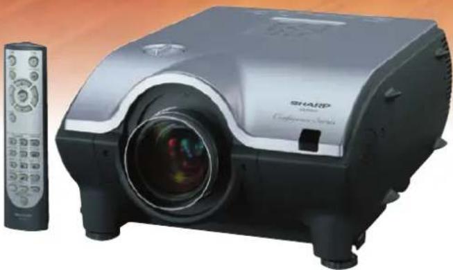
Exterior view of a Sharp projector with a remote control unit (no visible text or symbols)IMPORTANT
For your assistance in reporting the loss or theft of your Color LCD Projector, please record the Serial Number located on the bottom of the projector and retain this information. Before recycling the packaging, please be sure that you have checked the contents of the carton thoroughly against the list of "Supplied Accessories" on page 15.
Model No.: XG-P25X
Serial No.:
This equipment complies with the requirements of Directives 89/336/EEC and 73/23/EEC as amended by 93/68/EEC.
The mains lead of this product is fitted with a non-rewireable (moulded) plug incorporating a 10A fuse. Should the fuse need to be replaced, a BSI or ASTA approved BS 1362 fuse marked for and of the same rating as above, which is also indicated on the pin face of the plug, must be used.
Always refit the fuse cover after replacing the fuse. Never use the plug without the fuse cover fitted. In the unlikely event of the socket outlet in your home not being compatible with the plug supplied, cut off the mains plug and fit an appropriate type.
DANGER:
The fuse from the cut-off plug should be removed and the cut-off plug destroyed immediately and disposed of in a safe manner.
Under no circumstances should the cut-off plug be inserted elsewhere into a 10A socket outlet, as a serious electric shock may occur.
To fit an appropriate plug to the mains lead, follow the instructions below:
IMPORTANT:
The wires in the mains lead are coloured in accordance with the following code:
Blue: Neutral
Brown: Live
As the colours of the wires in the mains lead of this product may not correspond with the coloured markings identifying the terminals in your plug, proceed as follows:
- The wire which is coloured blue must be connected to the plug terminal which is marked N or coloured black.
- The wire which is coloured brown must be connected to the plug terminal which is marked L or coloured red.
Ensure that neither the brown nor the blue wire is connected to the earth terminal in your three-pin plug. Before replacing the plug cover make sure that:
- If the new fitted plug contains a fuse, its value is the same as that removed from the cut-off plug.
- The cord grip is clamped over the sheath of the mains lead, and not simply over the lead wires. IF YOU HAVE ANY DOUBT, CONSULT A QUALIFIED ELECTRICIAN.
The supplied CD-ROM contains operation instructions in English, German, French, Swedish, Spanish, Italian, Dutch, Portuguese, Chinese (Traditional Chinese and Simplified Chinese), Korean and Arabic. Carefully read through the operation instructions before operating the LCD projector.
There are two important reasons for prompt warranty registration of your new SHARP LCD Projector, using the REGISTRATION CARD packed with the projector.
1. WARRANTY
This is to assure that you immediately receive the full benefit of the parts, service and labor warranty applicable to your purchase.
2. CONSUMER PRODUCT SAFETY ACT
To ensure that you will promptly receive any safety notification of inspection, modification, or recall that SHARP may be required to give under the 1972 Consumer Product Safety Act, PLEASE READ CAREFULLY THE IMPORTANT "LIMITED WARRANTY" CLAUSE. U.S.A. ONLY
WARNING:
High brightness light source. Do not stare into the beam of light, or view directly. Be especially careful that children do not stare directly into the beam of light.
WARNING:
To reduce the risk of fire or electric shock, do not expose this product to rain or moisture.
The lightning flash with arrowhead symbol, within an equilateral triangle, is intended to alert the user to the presence of uninsulated “dangerous voltage” within the product’s enclosure that may be of sufficient magnitude to constitute a risk or electric shock to persons.

The exclamation point within a triangle is intended to alert the user to the presence of important operating and maintenance (servicing) instructions in the literature accompanying the product.
WARNING:
FCC Regulations state that any unauthorized changes or modifications to this equipment not expressly approved by the manufacturer could void the user's authority to operate this equipment. U.S.A. ONLY
INFORMATION
This equipment has been tested and found to comply with the limits for a Class A digital device, pursuant to Part 15 of the FCC Rules. These limits are designed to provide reasonable protection against harmful interference when the equipment is operated in a commercial environment. This equipment generates, uses, and can radiate radio frequency energy and, if not installed and used in accordance with the operation manual, may cause harmful interference to radio communications. Operation of this equipment in a residential area is likely to cause harmful interference, in which case the user will be required to correct the interference at his own expense.
U.S.A. ONLY
The enclosed computer cable must be used with the device. The cable is provided to ensure that the device complies with FCC Class A verification.
WARNING:
This is a class A product. In a domestic environment this product may cause radio interference in which case the user may be required to take adequate measures.
WARNING:
The cooling fan in this projector continues to run for about 90 seconds after the projector is turned off. During normal operation, when turning the power off, always use the POWER OFF button on the projector or on the remote control. Ensure the cooling fan has stopped before disconnecting the power cord.
DURING NORMAL OPERATION, NEVER TURN THE PROJECTOR OFF BY DISCONNECTING THE POWER CORD. FAILURE TO OBSERVE THIS WILL RESULT IN PREMATURE LAMP FAILURE.
PRODUCT DISPOSAL
This projector utilizes tin-lead solder, and a pressurized lamp containing a small amount of mercury. Disposal of these materials may be regulated due to environmental considerations. For disposal or recycling information, please contact your local authorities or, if you are located in the United States of America, the Electronics Industries Alliance: www.eiae.org.
natural_image
Technical line drawing of a computer monitor with ventilation slots and a handle (no text or symbols)
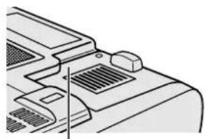
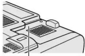
LAMP REPLACEMENT CAUTION
BEFORE REMOVEING THE SCREW, DISCONNECT POWER CORD. HOT SURFACE INSIDE ALLOW 1 HOUR TO COOL BEFORE REPLACING THE LAMP. REPLACE WITH SAVE SHARP LAMP UNIT TYPE BQC-XGP25X/1 ONLY. UV RADIATION: CAN CAUSE EYE DAMAGE. TURN OFF LAMP BEFORE SERVICING MEDIUM PRESSURE LAMP: RISK OF EXPLOSION POTENTIAL HAZARD OF GLASS PARTICLES IF LAMP HAS RUPTURED. HANDLE WITH CARE. SEE OPERATION MANUAL.
Caution Concerning the Lamp Replacement
See "Replacing the Lamp" on pages 64 and 65.
CAUTION: Please read all of these instructions before you operate this product and save these instructions for later use.
Electrical energy can perform many useful functions. This product has been engineered and manufactured to ensure your personal safety. But IMPROPER USE CAN RESULT IN POTENTIAL ELECTRICAL SHOCK OR FIRE HAZARD. In order not to defeat the safeguards incorporated into this LCD Projector, observe the following basic rules for its installation, use and servicing.
1. Read Instructions
All the safety and operating instructions should be read before the product is operated.
2. Retain Instructions
The safety and operating instructions should be retained for future reference.
3. Heed Warnings
All warnings on the product and in the operating instructions should be adhered to.
4. Follow Instructions
All operating and use instructions should be followed.
5. Cleaning
Unplug this product from the wall outlet before cleaning. Do not use liquid cleaners or aerosol cleaners. Use a damp cloth for cleaning.
6. Attachments
Do not use attachments not recommended by the product manufacturer as they may cause hazards.
7. Water and Moisture
Do not use this product near water-for example, near a bathtub, wash bowl, kitchen sink, or laundry tub; in a wet basement; or near a swimming pool; and the like.
8. Accessories
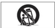
Do not place this product on an unstable cart, stand, tripod, bracket, or table. The product may fall, causing serious injury to a child or adult, and serious damage to the product. Use only with a cart, stand, tripod, bracket, or table recommended by the manufacturer, or sold with the product. Any mounting of the product should follow the manufacturer's instructions, and should use a mounting accessory recommended by the manufacturer.
9. Transportation
A product and cart combination should be moved with care. Quick stops, excessive force, and uneven surfaces may cause the product and cart combination to overturn.
10. Ventilation
Slots and openings in the cabinet are provided for ventilation to ensure reliable operation of the product and to protect it from overheating, and these openings must not be blocked or covered. The openings should never be blocked by placing the product on a bed, sofa, rug, or other similar surface. This product should not be placed in a built-in installation such as a bookcase or rack unless proper ventilation is provided or the manufacturer's instructions have been adhered to.
11. Power Sources
This product should be operated only from the type of power source indicated on the marking label. If you are not sure of the type of power supply to your home, consult your product dealer or local power company. For products intended to operate from battery power, or other sources, refer to the operating instructions.
12. Grounding or Polarization
This product is provided with one of the following types of plugs. If the plug should fail to fit into the power outlet, please contact your electrician.
Do not defeat the safety purpose of the plug.
a. Two-wire type (mains) plug.
b. Three-wire grounding type (mains) plug with a grounding terminal.
This plug will only fit into a grounding type power outlet.
13. Power-Cord Protection
Power-supply cords should be routed so that they are not likely to be walked on or pinched by items placed upon or against them, paying particular attention to cords at plugs, convenience receptacles, and the point where they exit from the product.
14. Lightning
For added protection for this product during a lightning storm, or when it is left unattended and unused for long periods of time, unplug it from the wall outlet and disconnect the cable system. This will prevent damage to the product due to lightning and power-line surges.
15. Overloading
Do not overload wall outlets, extension cords, or integral convenience receptacles as this can result in a risk of fire or electric shock.
16. Object and Liquid Entry
Never push objects of any kind into this product through openings as they may touch dangerous voltage points or short-out parts that could result in a fire or electric shock. Never spill liquid of any kind on the product.
17. Servicing
Do not attempt to service this product yourself as opening or removing covers may expose you to dangerous voltage or other hazards. Refer all servicing to qualified service personnel.
18. Damage Requiring Service
Unplug this product from the wall outlet and refer servicing to qualified service personnel under the following conditions:
a. If the power-supply cord or plug is damaged.
b. If liquid has been spilled, or objects have fallen into the product.
c. If the product has been exposed to rain or water.
d. If the product does not operate normally by following the operating instructions. Adjust only those controls that are covered by the operating instructions, as an improper adjustment of other controls may result in damage and will often require extensive work by a qualified technician to restore the product to normal operation.
e. If the product has been dropped or damaged in any way.
f. If the product exhibits a distinct change in performance, this indicates a need for service.
19. Replacement Parts
When replacement parts are required, be sure the service technician has used replacement parts specified by the manufacturer or have the same characteristics as the original part. Unauthorized substitutions may result in fire, electric shock, or other hazards.
20. Safety Check
Upon completion of any service or repairs to this product, ask the service technician to perform safety checks to determine that the product is in proper operating condition.
21. Wall or Ceiling Mounting
This product should be mounted to a wall or ceiling only as recommended by the manufacturer.
22. Heat
This product should be situated away from heat sources such as radiators, heat registers, stoves, or other products (including amplifiers) that produce heat.
- Microsoft and Windows are registered trademarks of Microsoft Corporation, in the United States and/or other countries.
• PC/AT is a registered trademark of International Business Machines Corporation in the United States. - Adobe Acrobat is a trademark of Adobe Systems Incorporated.
• Macintosh is a registered trademark of Apple Computer, Inc. in the United States and/or other countries. - All other company or product names are trademarks or registered trademarks of their respective companies.
- This software is based in part on the work of the Independent JPEG Group.
natural_image
Line drawing of a computer monitor with ventilation slots and a scroll wheel (no text or symbols)
LAMP REPLACEMENT CAUTION
BEFORE REMOVIDING THE SCREW, DISCONNECT POWER CORD. HOT SURFACE INSIDE ALLOW 1 HOUR TO COOL BEFORE REPLACING THE LAMP. REPLACE WITH SAME SHARP LAMP UNIT TYPE BQC-XGP25X/1 ONLY UV RADIATION: CAN CAUSE EYE DAMAGE. TURN OFF LAMP BEFORE SERVICING. MEDIUM PRESSURE LAMP: RISK OF EXPLOSION POTENTIAL HAZARD OF GLASS PARTICLES IF LAMP HAS RUPTURED. HANDLE WITH CARE. SEE OPERATION MANUAL
natural_image
Technical line drawing of a mechanical fan or housing component (no text or symbols)text_image
Illustration of a device with a red prohibition symbol overlaid, indicating no prohibition or prohibition in the use of this device.Caution Concerning the Lamp Replacement
See "Replacing the Lamp" on pages 64 and 65.
PRODUCT DISPOSAL
This projector utilizes tin-lead solder, and a pressurized lamp containing a small amount of mercury. Disposal of these materials may be regulated due to environmental considerations. For disposal or recycling information, please contact your local authorities or, if you are located in the United States of America, the Electronics Industries Alliance: www.eiae.org.
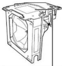
Caution Concerning the Lamp Unit
Potential hazard of glass particles if lamp ruptures. In case of lamp rupture, contact your nearest Sharp Authorized LCD Projector Dealer or Service Center for a replacement.
See "Replacing the Lamp" on pages 64 and 65.
Cautions Concerning the Setup of the Projector
For minimal servicing and to maintain high image quality, SHARP recommends that this projector be installed in an area free from humidity, dust and cigarette smoke. When the projector is subjected to these environments, the lens must be cleaned more often. As long as the projector is properly maintained in this manner, use in these environments will not reduce the overall operation life. Please note that all internal cleaning must be performed by a Sharp Authorized LCD Projector Dealer or Service Center.
Notes on Operation
- The exhaust vent, the lamp cage cover and adjacent areas may be extremely hot during projector operation. To prevent injury, do not touch these areas until they have sufficiently cooled.
- Allow at least 12 inches (30 cm) of space between the exhaust vent and the nearest wall or obstruction.
- If the cooling fan becomes obstructed, a protection device will automatically turn off the projector lamp. This does not indicate a malfunction. Remove the projector power cord from the wall outlet and wait at least 10 minutes. Then turn on the power by plugging the power cord back in. This will return the projector to the normal operating condition.

TEMP.

LAMP
natural_image
Line drawing of a vintage portable device with handle and front panel (no text or symbols)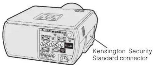
text_image
Kensington Security Standard connectorTemperature Monitor Function
If the projector starts to overheat due to setup problems or a dirty air filter, "TEMP." and "☒" will blink in the lower-left corner of the picture. If the temperature continues to rise, the lamp will turn off, the TEMPERATURE WARNING indicator on the projector will blink, and after a 90-second cooling-off period the power will shut off. Refer to "Lamp/Maintenance Indicators" on page 63, for details.
NOTE
- The cooling fan regulates the internal temperature, and its performance is automatically controlled. The sound of the fan may change during projector operation due to changes in the fan speed.
Lamp Monitor Function
When the projector is turned on after the lamp has been used for 1,400 hours, "LAMP" and "8" will blink in the lower-left corner of the picture to advise you to replace the lamp. See pages 64 and 65 for lamp replacement. If the lamp has been used for 1,500 hours, the projector power will automatically turn off and the projector will enter standby mode. Refer to "Lamp/Maintenance Indicators" on page 63, for details.
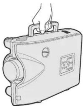
Using the Carrying Handle
When transporting the projector, carry it by the carrying handle on the side.
CAUTION
• Always put on the lens cap to prevent damage to the lens when transporting the projector.
- Do not lift or carry the projector by the lens or the lens cap as this may damage the lens.
Using the Kensington Lock
This projector has a Kensington Security Standard connector for use with a Kensington MicroSaver Security System. Refer to the information that came with the system for instructions on how to use it to secure the projector.
1. High-end LCD Projector with Ultra High Brightness
- AC 270 W Lamp
Use AC 270 W lamp for excellent color uniformity and ultra high brightness.
2. Computer Compatibility
- Compatible with resolutions including VGA-SVGA (expanded), XGA (true resolution) and SXGA-UXGA (compressed) as well as DTV formats (480I, 480P, 580I, 580P, 720P, 1035I and 1080I).
3. XGA Image Quality
- OCS LCD panel enhances color uniformity.
- Various other circuits are also used to provide high quality video images.
4. Computer & Video Integrated Composer Technology
- New Progressive Mode
I/P conversion with new algorithm used to achieve beautiful image quality.
• Enhanced Up-scaling and Digital Image Enlargement
Enables sharper image quality without jaggies even for enlarged images.
- Superior 16:9 Image
4:3 images can be converted to 16:9 images using Smart Stretch (sides stretched, center untouched), previously not achievable with LCD projectors.
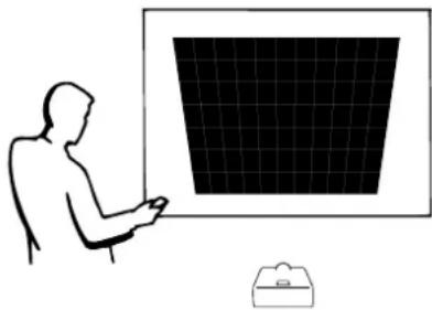
- Intelligent Digital Keystone Correction
Smooths out jaggies on keystone images and compresses the image not only horizontally but vertically keeping the 4:3 aspect ratio. Even if the 4:3 aspect ratio changes due to lens shift, v-size adjustment allows you to keep this ratio.
- New Intelligent Compression
Efficiently compresses UXGA (1,600 × 1,200) images to XGA (1,024 × 768).
• Enhanced three-two pull down
Converts cinema mode DVD images transformed with three-two pull down enhancement to progressive mode images for easier viewing by Film Mode.
• Dynamic GAMMA Correction
Optimizing GAMMA correction frame by frame in real time.
5. 3D Digital Uniformity and Digital Convergence
- Three-Dimensional Digital Uniformity compensates uneven picture brightness even for pictures at any brightness level from white to dark. And, with Digital Convergence, a slight distortion of convergence can be adjusted on the service menu screen without having to touch the LCD panel.
natural_image
Silhouette of a person using a computer monitor with a grid screen (no text or symbols visible)6. Network Capability
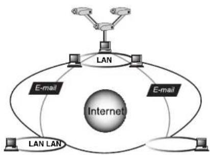
• Self-Diagnosis/Projector Status
Self-diagnosis/Projector status function sends e-mail messages to a specified computer about lamp usage time and any malfunctions.
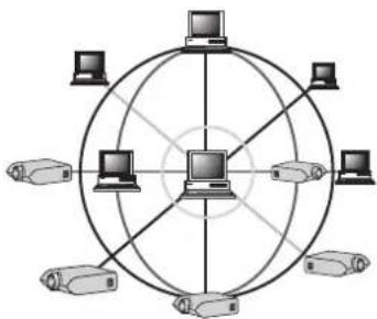
• Multiple & Group Projector Control
Up to 250 projectors can be controlled over a network. Projector RS-232C OUT can be used for daisy chain connection.
- Simple Stacking and Videowall Display
Comes with software for easy stacking and videowall processing even for input from a single source.
flowchart
graph TD
    A["Central Computer"] --> B["Computer 1"]
    A --> C["Computer 2"]
    A --> D["Computer 3"]
    A --> E["Computer 4"]
    A --> F["Computer 5"]
    A --> G["Computer 6"]
    A --> H["Computer 7"]
    A --> I["Computer 8"]
    A --> J["Computer 9"]
    A --> K["Computer 10"]
    A --> L["Computer 11"]
    A --> M["Computer 12"]
    A --> N["Computer 13"]
    A --> O["Computer 14"]
    A --> P["Computer 15"]
    A --> Q["Computer 16"]
    A --> R["Computer 17"]
    A --> S["Computer 18"]
    A --> T["Computer 19"]
    A --> U["Computer 20"]
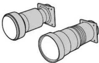
7. Two Optional Lenses for Maximum Flexibility
- Screw mount type: Fixed Wide Lens, Tele-Zoom Lens
8. Multiple Input and Output Terminals
• BNC Terminal for RGB/Component/Video Signal
• PC Digital Input (DVI-I)
- Output terminal with VAO (variable audio output) support
natural_image
Illustration of two cylindrical mechanical components with flanged ends and threaded end caps (no text or symbols)9. Easy Setup
- Lens Shift, Power Zoom & Focus, Digital Keystone Correction
• High Speed Auto Sync Technology
10. Useful Features
• Picture-in-Picture, Digital Enlargement, Freeze
- Customizable Startup Screen & Background Screen
11. Application Software
- “Sharp Advanced Presentation Software Professional Edition” (Network and Remote Control)
flowchart
graph TD
    A["Internet"] --> B["LAN"]
    A --> C["E-mail"]
    A --> D["LAN LAN"]
    A --> E["E-mail"]
    B --> F["Computer"]
    C --> G["Computer"]
    D --> H["Computer"]
    E --> I["Computer"]
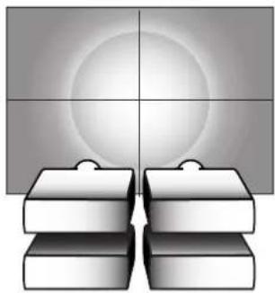
natural_image
Abstract 3D illustration of stacked blocks with a central circular gradient, no text or symbols present
Contents

Important Information
Introduction 1
IMPORTANT SAFEGUARDS .... 3
Outstanding Features 7
Contents 9
How to Access the PDF Operation Manuals 11
Part Names.... 12
Using the Remote Control 14
Accessories 15
Setup & Connections
Connections.... 16
Power Supply 16
Projecting Computer Images 16
Watching Video Images 18
Watching Component Video Images ..... 19
Controlling Projectors 20
Connecting to a Monitor 21
For Better Sound 21
Power ON/OFF 22
Setting Up the Screen 23
Using the Adjustment Feet 23
Using the Lens Shift 23
LENS Button 24
Adjusting the Projection Distance ..... 25
Image Projection 30
Rear Projection 30
Projection Using a Mirror 30
Ceiling-mount Projection 30
Operation Buttons
Using the Operation Buttons ...... 31
Selecting the Input Signal Source 31
Adjusting the Volume.... 31
Muting the Sound 31
Superimposing a Black Screen.... 32
Displaying a Still Image 32
Magnifying a Specific Portion of an Image 33
Displaying and Setting the Break Timer ... 34
Computer Image Adjustments using AUTO SYNC 34
Adjusting the Picture Aspect Ratio...... 35
Gamma Correction Function 37

Basic Operation
Using the GUI (Graphical User
Interface) Menu Screen 38
Basic Operations 38
Menu Bars 39
Adjusting the Picture 41
Adjusting the Computer Images (RGB menu only) 43
Adjusting the Sound 46
Displaying Dual Pictures (RGB menu only) 47
Reducing Image Noise [DNR] (VIDEO menu only) 47
Turning On/Off the On-screen Display ... 48
Setting the Video Signal (VIDEO menu only) 48
Selecting a Background Image...... 49
Selecting a Startup Image.... 49
Selecting the Economy Mode 50
Confirming the Lamp Usage Time ..... 51
Reversing/Inverting Projected Images ... 51
Setting the Stacking Mode 52
Locking the Operation Buttons on the Projector.... 52
Deselecting Inputs 53
Selecting the Transmission Speed (RS-232C) 53
Controlling Multiple Projectors with ID Numbers 54
Protecting Important Settings with a Password 55
Selecting the On-screen Display Language.... 56
Displaying the Adjustment Settings ..... 56
Multiple Function
Using Extended Functionality Features 57

Maintenance & Troubleshooting
Lamp/Maintenance Indicators 63
Replacing the Lamp 64
Replacing the Air Filter 66
Troubleshooting 67
For SHARP Assistance 68

Appendix
Connecting Pin Assignments 69
(RS-232C) Specifications and Command Settings.... 70
Wired Remote Control Terminal Specifications 73
Compatibility Chart 74
Dimensions 75
Specifications 76
Glossary 77
Index 78
PDF operation manuals in several languages are included in the Projector Manual and Technical Reference CD-ROM. To utilize these manuals, you need to install Adobe Acrobat Reader on your PC (Windows or Macintosh). If you have not installed Acrobat Reader yet, you can download it from the Internet (http://www.adobe.com) or install it from the CD-ROM.
To Install Acrobat Reader from the CD-ROM
For Windows:
①Insert the CD-ROM in the CD-ROM drive.
② Double click on the "My Computer" icon.
③Double click on the "CD-ROM" drive.
④ Double click on the "ACROBAT" folder.
⑤Double click on the language (name of the folder) that you want to view.
⑥Double click on the desired installation program and follow the instructions on the screen.
For Macintosh:
①Insert the CD-ROM in the CD-ROM drive.
② Double click on the "CD-ROM" icon.
③ Double click on the "ACROBAT" folder.
④Double click on the language (name of the folder) that you want to view.
⑤Double click on the desired installation program and follow the instructions on the screen.
For other operating systems:
Please download Acrobat Reader from the Internet (http://www.adobe.com).
For other languages:
If you prefer using Acrobat Reader for languages other than those included in the CD-ROM, please download the appropriate version from the Internet.
Accessing the PDF Manuals
For Windows:
①Insert the CD-ROM in the CD-ROM drive.
② Double click on the "My Computer" icon.
③Double click on the "CD-ROM" drive.
④Double click on the "MANUALS" folder.
⑤Double click on the language (name of the folder) that you want to view.
⑥ Double click on the "P25X" pdf file to access the projector manual.
For Macintosh:
①Insert the CD-ROM in the CD-ROM drive.
② Double click on the "CD-ROM" icon.
③Double click on the "MANUALS" folder.
④Double click on the language (name of the folder) that you want to view.
⑤ Double click on the "P25X" pdf file to access the projector manual.
NOTE
- If the desired pdf file cannot be opened by double clicking the mouse, start Acrobat Reader first, then specify the desired file using the "File", "Open" menu.
- See the "readme.txt" file on the CD-ROM for important information on the CD-ROM not included in this operation manual.
Numbers next to the part names refer to the main pages in this manual where the topic is explained.
Projector
Front View
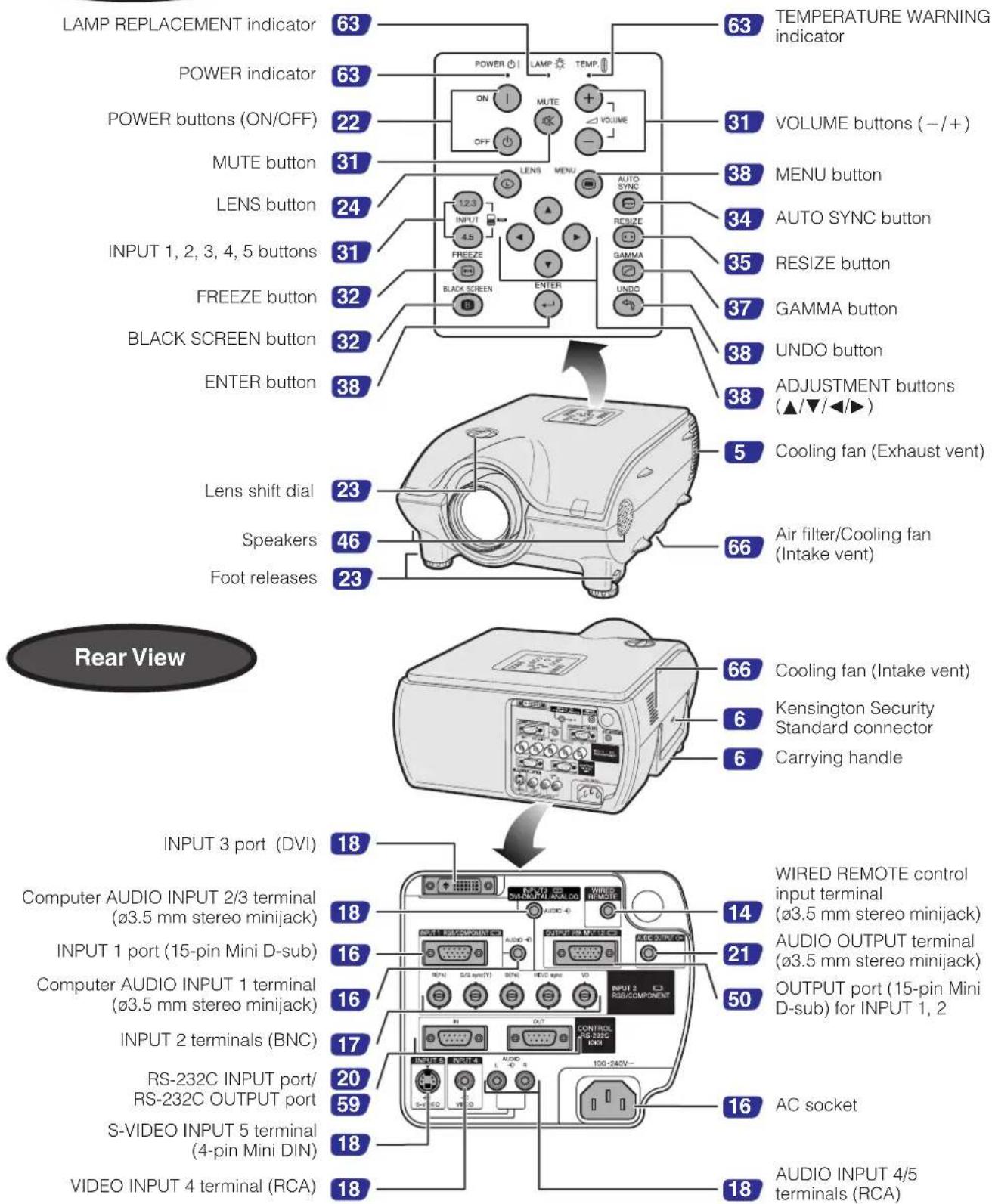
text_image
LAMP REPLACEMENT indicator POWER indicator POWER buttons (ON/OFF) MUTE button LENS button INPUT 1, 2, 3, 4, 5 buttons FREEZE button BLACK SCREEN button ENTER button Lens shift dial Speakers Foot releases 63 63 TEMPERATURE WARNING indicator POWER ON ON OFF LAMP TEMP VOLUME buttons (-/+) 31 MENU button AUTO SYNC button 34 AUTO SYNC button RESIZE button 35 RESIZE button GAMMA button 37 GAMMA button 38 UNDO button ADJUSTMENT buttons (▲/▼/◄►) 5 Cooling fan (Exhaust vent) 66 Air filter/Cooling fan (Intake vent) 66 Kensington Security Standard connector 6 Carrying handle 66 COOLING FAN (Intake vent) 6 KENSINGTON Security Standard connector 6 Carrying handle INPUT 3 port (DVI) 18 Wired REMOTE control input terminal (ø3.5 mm stereo minijack) 14 AUDIO OUTPUT terminal (ø3.5 mm stereo minijack) 21 OUTPUT port (15-pin Mini D-sub) for INPUT 1, 2 16 INPUT 1 port (15-pin Mini D-sub) 16 INPUT 2 terminals (BNC) 17 RS-232C INPUT port/RS-232C OUTPUT port 20 S-VIDEO INPUT 5 terminal (4-pin Mini DIN) 18 AC socket 18 AUDIO INPUT 4/5 terminals (RCA)Numbers next to the part names refer to the main pages in this manual where the topic is explained.
Remote Control
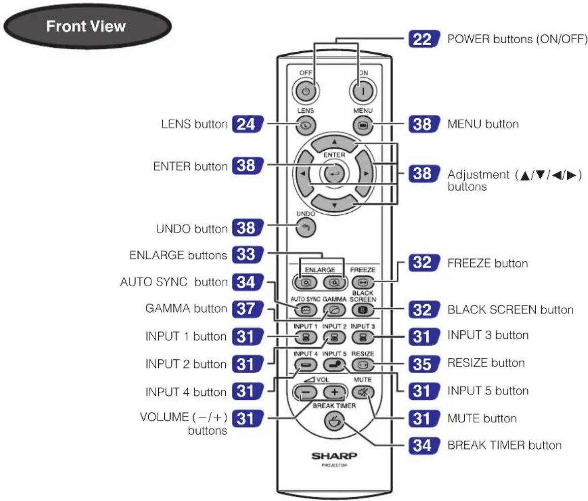
text_image
Front View 22 POWER buttons (ON/OFF) OFF ON LENS MENU 38 MENU button 38 ENTER button 38 Adjustment (▲/▼/◄/►) buttons UNDO button 38 ENLARGE buttons 33 FREEZE button AUTO SYNC button 34 AUTO SYNC GAMA BLACK SCREEN GAMMA button 37 BLACK SCREEN button INPUT 1 button 31 INPUT 3 button INPUT 2 button 31 RESIZE button INPUT 4 button 31 INPUT 5 button VOLUME (-/+) buttons 31 MUTE button BREAK TIMER button 34 BREAK TIMER button SHARP PROJECTOR
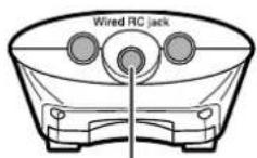
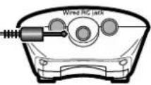
14 Wired RC jack (ø3.5 mm minijack)
Inserting the batteries
| 1 Press the tab and lift open the battery cover in the direction of the arrow. | 2 Insert two R-6 batteries ("AA" size, UM/SUM-3, HP-7 or similar), making sure the polarities match the + and - marks inside the battery compartment. | 3 Insert the tabs on the end of the battery cover into their slots and press the cover into position. |
Battery cov 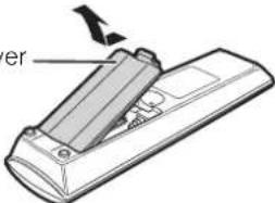 | 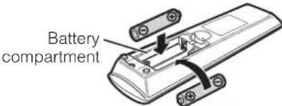 | 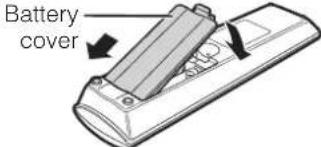 |
Incorrect use of the batteries may cause them to leak or explode. Please follow the precautions below.
CAUTION
- Insert the batteries making sure the polarities correctly match the + and - marks inside the battery compartment.
- Batteries of different types have different properties, therefore do not mix batteries of different types.
- Do not mix new and old batteries.
This may shorten the life of new batteries of may cause old batteries to leak.
- Remove the batteries from the remote control once they have run out, as leaving them can cause them to leak.
Battery fluid from leaked batteries is harmful to your skin, therefore be sure to first wipe them and then remove them using a cloth. - The batteries included with this projector may be used up over a short period, depending on how they are kept. Be sure to replace them as soon as possible with new batteries.
- Remove the batteries from the remote control if you will not be using the remote control for a long time.
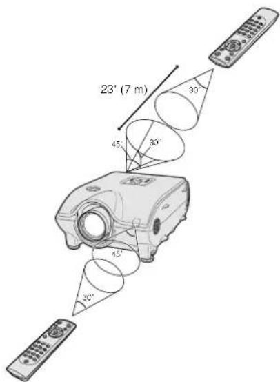
Available Range of the Remote Control
The remote control can be used to control the projector within the ranges shown in the illustration.
NOTE
- The signal from the remote control can be reflected off a screen for easy operation. However, the effective distance of the signal may differ due to the screen material.
When using the remote control:
- Be sure not to drop, expose to moisture or high temperature.
- The remote control may malfunction under a fluorescent lamp. Under that circumstance, move the projector away from the fluorescent lamp.
text_image
23' (7 m) 45° 30° 30° 45° 30°Using as a Wired Remote Control
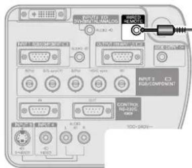
When the remote control cannot be used due to the range or positioning of the projector (rear projection, etc.), connect a 3.5 mm minijack cable (commercially available) from the wired RC jack on the bottom of the remote control to the WIRED REMOTE control input terminal on the rear of the projector.
text_image
POWER TO RUBSING ENLOGS INPUT 2 C RUBCOMPONENT CONTROL REG302C USB 100-540V~∅3.5 mm minijack cable (commercially available)
Supplied Accessories
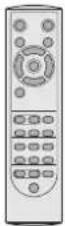
Remote control
RRMCGA048WJSA
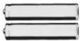
Two R-6 batteries ("AA" size, UM/SUM-3, HP-7 or similar)
Power cord
(1) (2) (3) (4)
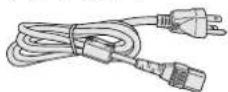
For U.S., Canada etc.
(11' 10", 3.6m)
QACCDA010WJPZ

For Europe, except U.K.
(6', 1.8m)
QACCV4002CEZZ
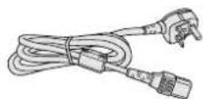
For U.K., Hong Kong and Singapore (6', 1.8m)
QACCBA012WJPZ
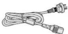
For Australia, New Zealand and Oceania (6', 1.8m)
QACCL3022CEZZ
NOTE
- Depending on the region, projectors only ship with one power cord (See above). Use the power cord that corresponds to the wall outlet in your country.
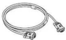
RGB cable
(9' 10", 3m)
QCNWGA012WJPZ
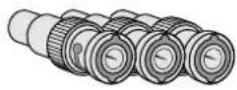
Three BNC-RCA adaptors
QPLGJ0107GEZZ
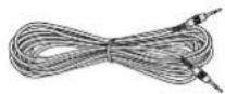
Computer audio cable
(ø3.5 mm stereo minijack cable)
(9' 10", 3m)
QCNWGA013WJPZ
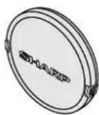
Lens cap
(attached)
PCAPH1056CESA
Extra air filter
PFILD0080CEZZ
Projector Manual and Technical Reference CD-ROM UDSKAA004WJZZ
Sharp Advanced Presentation
Software CD-ROM
UDSKAA005WJZZ
LCD projector operation manual
TINS-A133WJZZ
Quick reference guides
Sharp Advanced Presentation
Software installation guide
TINS-A139WJZZ
ID number seal
TLABZ0781CEZZ
Optional Accessories
DVI cable (9' 10" (3.0 m))
3 RCA to 15-pin D-sub cable (9' 10" (3.0 m))
Computer RGB cable (32' 10" (10.0 m))
AN-C3DV
AN-C3CP
AN-C10BM
(for IBM-PC, NEC PC-9821 and PC-98NX series)
AN-C10MC
(for Macintosh series)
AN-C10PC
(for NEC PC-98 series (Except NEC PC-9821 and PC-98NX series)
5 BNC to 15-pin D-sub cable (9' 10" (3.0 m))
RS-232C serial control cable (32' 10" (10.0 m))
DVI to 15-pin D-sub adaptor (7.9" (20 cm))
AN-C3BN
AN-C10RS
AN-A1DV
NOTE
- All cables may not be available in all regions. Please check with your nearest Sharp Authorized LCD Projector Dealer or Service Center.

Power Supply
Connecting the Power Cord
Plug the supplied power cord into the AC socket on the rear of the projector.
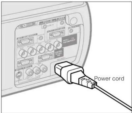
text_image
Power cordMake the necessary connections before proceeding. Connect the power cord to a wall outlet.
The POWER indicator lights up red and the projector enters standby mode.
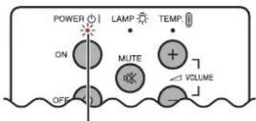
text_image
POWER LAMP TEMP ON MUTE VOLUME OFFPOWER indicator
NOTE
- If the bottom filter cover is not securely installed, the POWER indicator blinks.

Projecting Computer Images
Connecting the Projector to a Computer
You can connect your projector to a computer for projection of full color computer images.
Connecting to a computer using the standard 15-pin Input
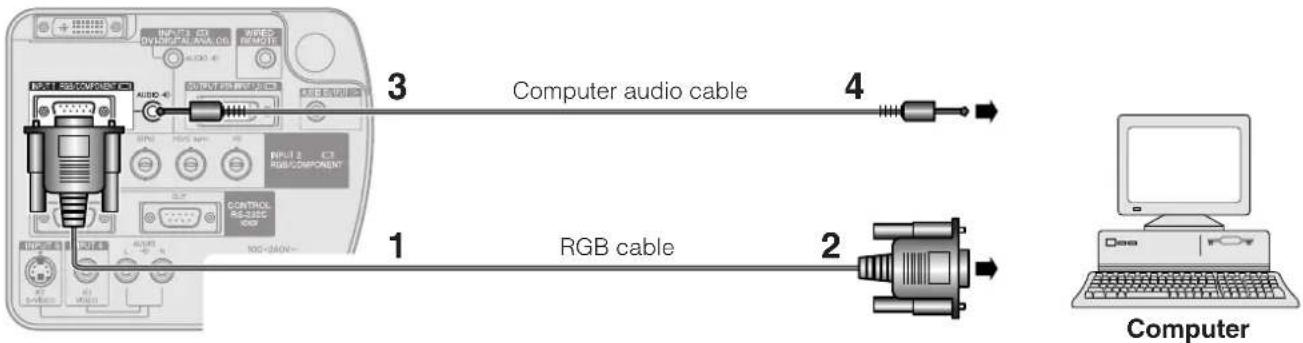
text_image
3 Computer audio cable 4 1 RGB cable 2 Computer1 Connect one end of the supplied RGB cable to the INPUT 1 port on the projector.
2 Connect the other end to the monitor output port on the computer. Secure the connectors by tightening the thumb screws.
3 To use the built-in audio system, connect one end of the supplied computer audio cable to the AUDIO INPUT 1 terminal on the projector.
4 Connect the other end to the audio output terminal on the computer.
CAUTION
- Before connecting, be sure to turn both the projector and the computer off. After making all connections, turn the projector on first. The computer should always be turned on last.
NOTE
- Please read the computer's operation manual carefully before making connections.
- Refer to page 74 "Compatibility Chart" for a list of computer signals compatible with the projector. Use with computer signals other than those listed may cause some of the functions not to work.
- A 3.5 mm stereo minijack to stereo RCA audio cable adaptor may be necessary.
When connecting this projector to a computer, select "RGB" for "Signal Type" on the GUI menu. (See page 41.)
NOTE
- A Macintosh adaptor may be required for use with some Macintosh computers. Contact your nearest Sharp Authorized LCD Projector Dealer or Service Center.
-
AUDIO INPUT 1 can be used to input audio corresponding to the INPUT 1.
-
This projector uses a 5 BNC computer input to prevent deterioration of image quality.
- Connect the R (PR), G/G sync (Y), B (PB), HD/C sync and VD cables (sold separately) to the correct input terminals on the projector and an RGB switcher (sold separately) connected to the computer, or connect a 5 BNC cable (sold separately) directly from the input terminals on the projector to the computer.
Connecting to an external RGB switcher or other compatible computers using the BNC Input (Typically used in larger installations)
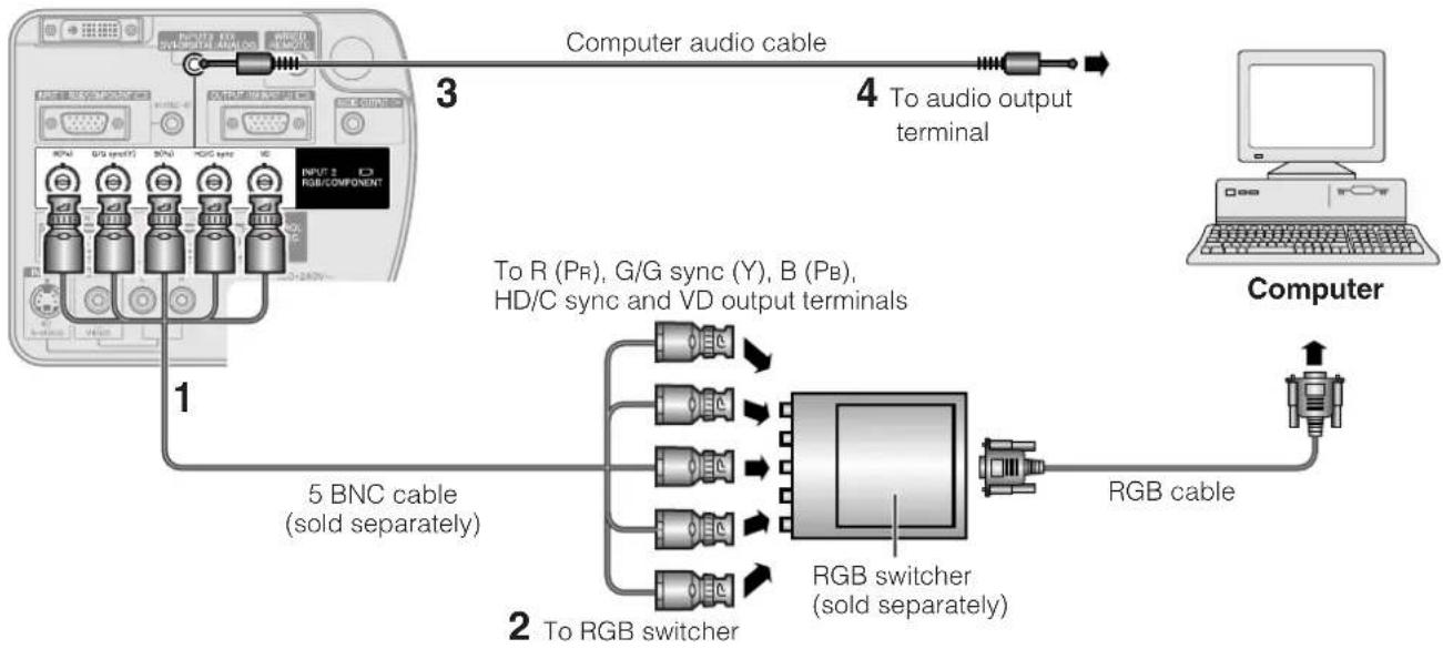
flowchart
graph LR
    A["Computer"] -->|1| B["5 BNC cable (sold separately)"]
    A -->|2| C["RGB switcher (sold separately)"]
    A -->|3| D["Computer audio cable"]
    D -->|4| E["To audio output terminal"]
    B --> F["RGB cable"]
    C --> G["RGB switcher (sold separately)"]
    style A fill:#f9f,stroke:#333
    style B fill:#ccf,stroke:#333
    style C fill:#cfc,stroke:#333
    style D fill:#fcc,stroke:#333
1 Connect each BNC connector of a 5 BNC cable to the corresponding INPUT 2 terminals on the projector.
2 Connect the other end of the 5 BNC cable to the corresponding BNC terminals on the external RGB switcher. Connect the RGB switcher to the computer using a RGB cable.
3 To use the built-in audio system, connect one end of the supplied computer audio cable to the AUDIO INPUT 2/3 terminal on the projector.
4 Connect the other end to the audio output terminal on the computer or external audio system.
NOTE
- A 3.5 mm stereo minijack to stereo RCA audio cable adaptor may be necessary.
When connecting the projector to a compatible computer other than a PC (VGA/SVGA/XGA/SXGA/UXGA) or Macintosh (i.e. Workstation), a separate cable may be needed. Please contact your dealer for more information.
When connecting this projector to a computer, select "RGB" for "Signal Type" on the GUI menu. (See page 41.)
NOTE
- Connecting computers other than the recommended types may result in damage to the projector, the computer, or both.
- AUDIO INPUT 2/3 can be used to input audio corresponding to the INPUT 2/3.
"Plug and Play" function (when connecting to a 15-pin terminal)
- This projector is compatible with VESA-standard DDC 1/DDC 2B. The projector and a VESA DDC compatible computer will communicate their setting requirements, allowing for quick and easy setup.
- Before using the "Plug and Play" function, be sure to turn on the projector first and the connected computer last.
NOTE
- The DDC "Plug and Play" function of this projector operates only when used in conjunction with a VESA DDC compatible computer.
Connecting to a computer using the direct digital input port
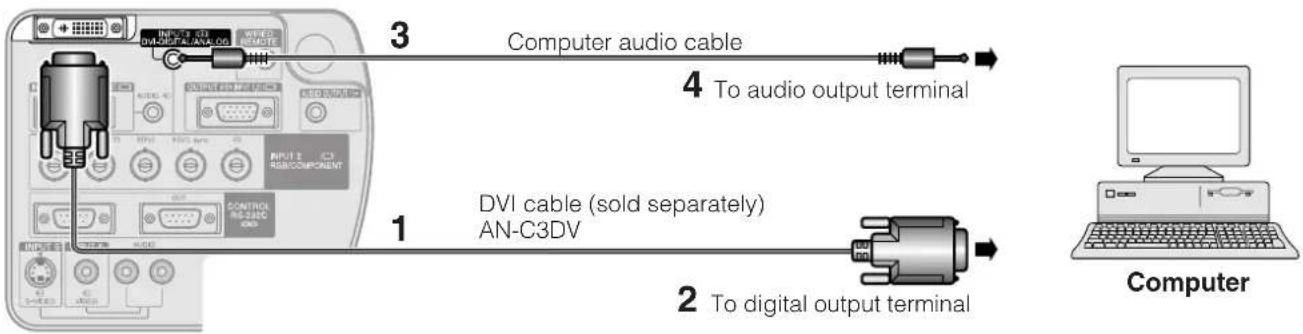
text_image
Computer audio cable 4 To audio output terminal 1 DVI cable (sold separately) AN-C3DV 2 To digital output terminal Computer1 Connect one end of the DVI cable to the INPUT 3 port on the projector.
2 Connect the other end to the corresponding terminal on a computer.
3 To use the built-in audio system, connect one end of the supplied computer audio cable to the AUDIO INPUT 2/3 terminal on the projector.
4 Connect the other end to the audio output terminal on the computer.
NOTE
- This DVI port is DVI version 1.0 compatible. Therefore when the signal is input from copy guard system compatible (DVI version 2.0) equipment, no signal will be received.
- The analog RGB signal inputs on the DVI port are only compatible with separate sync.

Watching Video Images
Connecting to a VCR, laser disc player and other audiovisual equipment using the standard video Input
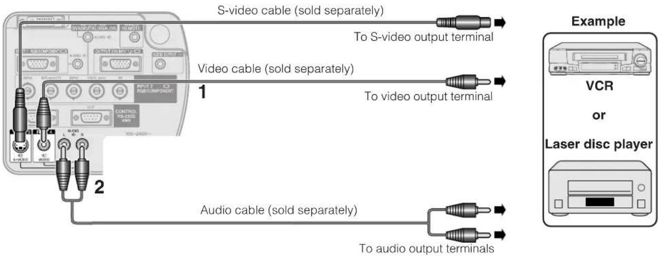
text_image
S-video cable (sold separately) To S-video output terminal Video cable (sold separately) 1 To video output terminal Audio cable (sold separately) To audio output terminals Example VCR or Laser disc player1 Connect the yellow RCA connectors to the corresponding yellow VIDEO INPUT 4 terminal on the projector and the Video output terminal on the video source.
2 To use the built-in audio system, connect the red and white RCA connectors to the corresponding red and white AUDIO INPUT 4/5 terminals on the projector and the Audio output terminals on the video source.
The S-VIDEO INPUT 5 terminal uses a video signal system in which the picture is separated into a color and a luminance signal to realize a higher-quality image.
NOTE
- For higher quality video, you may use the S-VIDEO INPUT 5 terminal on the projector. S-video cable is sold separately.
- If your video equipment does not have an S-video output terminal, use a composite video cable.
A CA
CAUTION
- Always turn off the projector before connecting to video equipment, in order to protect both the projector and the equipment being connected.
Connecting to a DVD video player, DTV\* decoder and other component video equipment using the 5 BNC Input
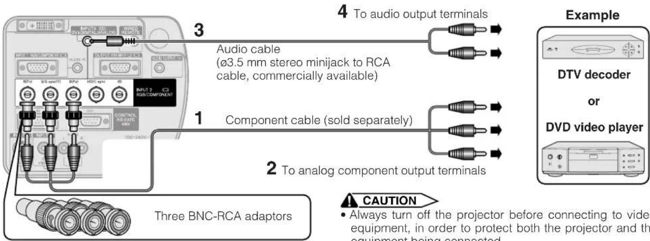
text_image
3 4 To audio output terminals Audio cable (ø3.5 mm stereo minijack to RCA cable, commercially available) 1 Component cable (sold separately) 2 To analog component output terminals Example DTV decoder or DVD video player Three BNC-RCA adaptors CAUTION • Always turn off the projector before connecting to video equipment, in order to protect both the projector and the equipment being connected1 Connect each BNC connector of a component cable to the corresponding BNC INPUT 2 terminals on the projector.
2 Connect the other end of the cable to the corresponding terminals on a DVD video player or DTV decoder.
3 To use the built-in audio system, connect one end of an audio cable (sold separately) to the AUDIO INPUT 2/3 terminal on the projector.
4 Connect the other end to the audio output terminal on the DVD video player or DTV decoder.
NOTE
- BNC-RCA adaptors are included for use with RCA type cables and sources.
- A 3.5 mm stereo minijack to stereo RCA audio cable adaptor may be necessary.
When connecting this projector to a DVD video player or DTV decoder, select "Component" for "Signal Type" on the GUI menu. (See page 41.)
*DTV is the umbrella term used to describe the new digital television system in the United States.
Connecting to a computer using the RS-232C Port
When the RS-232C IN port on the projector is connected to a computer with an RS-232C serial control cable (cross type, sold separately), the computer can be used to control the projector and check the status of the projector. See pages 70, 71 and 72 for details.
Connect an RS-232C serial control cable (cross type, sold separately) to the serial port on the computer. See page 69 for recommended connection of an RS-232C serial control cable.
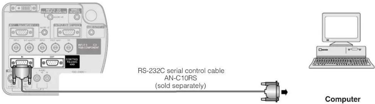
text_image
RS-232C serial control cable AN-C10RS (sold separately) Computer

CAUTION
- Do not connect or disconnect an RS-232C cable to or from the computer while it is on. This may damage your computer.
NOTE
- RS-232C function may not operate if your computer port is not correctly set up. Please refer to the operation manual of the computer for details on setting up/installing the correct mouse driver.
Daisy chain connection
When controlling multiple projectors, or making stack projection using the accompanied Sharp Advanced Presentation Software Professional Edition, projectors need to be daisy-chained.
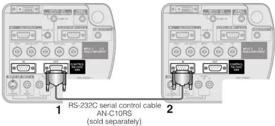
text_image
1 RS-232C serial control cable AN-C10RS (sold separately) 21 Connect one end of the RS-232C cable to the RS-232C OUT port on the projector.
2 Connect the other end to the RS-232C IN port on another projector.

Connecting to a Monitor
By connecting the OUTPUT terminal on the projector to the RGB terminal on a monitor using an RGB cable (commercially available), you can display the computer image both on the projector and on the monitor.
1 Connect one end of the computer RGB cable (commercially available) to the RGB (analog) OUTPUT port on the projector.
2 Connect the other end of the computer RGB cable to the RGB (analog) INPUT port on the monitor.
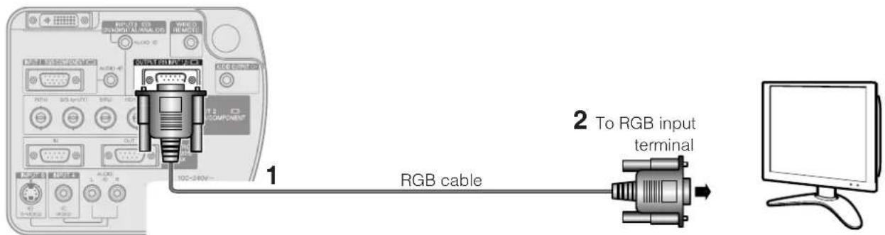
text_image
1 RGB cable 2 To RGB input terminalNOTE
- The image source from INPUT 1 or 2 can display using the OUTPUT terminal. This doesn't apply to the image source from INPUT 3,4, or 5.

For Better Sound
Connecting to an amplifier and other audio components
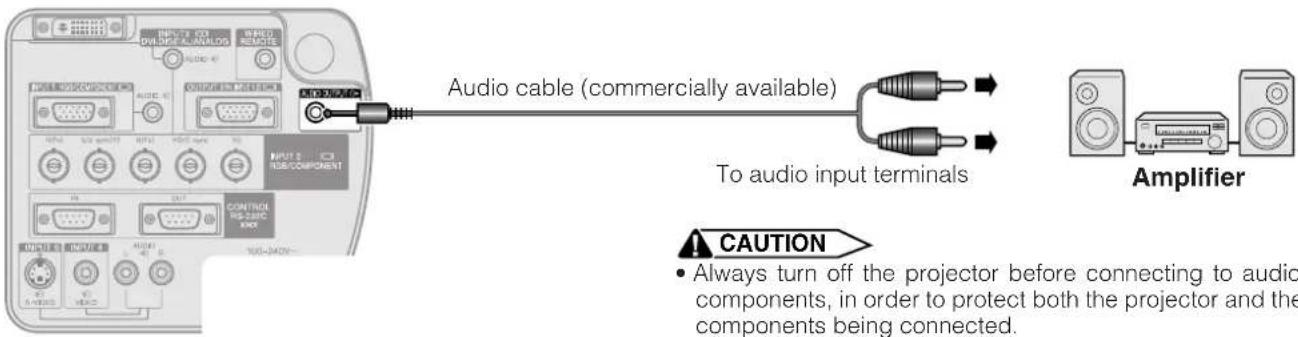
text_image
Audio cable (commercially available) To audio input terminals Amplifier CAUTION • Always turn off the projector before connecting to audio components, in order to protect both the projector and the components being connected.NOTE
- By using external audio components, the volume can be amplified for better sound.
- The AUDIO OUTPUT terminal allow you to output audio to audio components from the selected AUDIO INPUT 1 to 5 terminals connected to audiovisual equipment.
- For details on Variable Audio Output (VAO) and Fixed Audio Output (FAO), see page 46.
- A 3.5 mm stereo minijack to stereo RCA audio cable adaptor may be necessary.
Projector Remote control
text_image
POWER LAMP TEMP ON MUTE VOLUME OFF LENS MENU AUTO SYNC RESIZE GAMMA UNDO 12.3 INPUT 4.5 FREEZE BLACK SCREEN ENTER ON/OFF OFF ON LE ENTER UNDO SMARGE FREEZE AUTO SYNC GAMA GREEN INPUT 1 INPUT 2 INPUT 3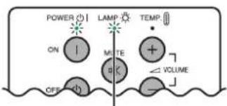
text_image
POWER ON OFF LAMP MUTE TEMP + VOLUMELAMP REPLACEMENT indicator
On-screen Display

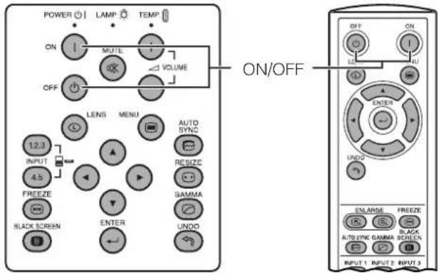
Press POWER ON.
- The blinking green LAMP REPLACEMENT indicator shows that the lamp is warming up. Wait until the indicator stops blinking before operating the projector.
- If the power is turned off and then immediately turned on again, it may take a short while before the lamp turns on.
NOTE
- After the projector is unpacked and turned on for the first time, a slight odor may be emitted from the exhaust vent. This odor will soon disappear with use.
When the power is on, the LAMP REPLACEMENT indicator lights, indicating the status of the lamp.
Green: Lamp is ready.
Green blinking: Warming up.
Red: Change the lamp.
Press POWER OFF.
Press POWER OFF again while the message is displayed to turn off the power.
NOTE
- If you accidentally pressed POWER OFF and do not want to turn off the power, wait until the power off screen disappears.
- When the power is turned off, the POWER indicator will light up red and the cooling fan will run for about 90 seconds. The projector will then enter standby mode.
- Wait until the cooling fan stops before disconnecting the power cord.
- The power can be turned on again by pressing POWER ON. When the power is turned on, the POWER indicator and the LAMP REPLACEMENT indicator light green.
- The POWER indicator blinks if the bottom filter cover is not securely installed.
WARNING:
The cooling fan in this projector continues to run for about 90 seconds after the projector is turned off. During normal operation, when turning the power off always use the POWER OFF button on the projector or on the remote control. Ensure the cooling fan has stopped before disconnecting the power cord. DURING NORMAL OPERATION, NEVER TURN THE PROJECTOR OFF BY DISCONNECTING THE POWER CORD. FAILURE TO OBSERVE THIS WILL RESULT IN PREMATURE LAMP FAILURE.

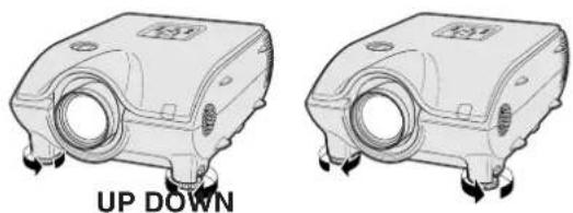
Using the Adjustment Feet
1
natural_image
Illustration of hands holding a mechanical component with arrows indicating force or movement (no text or symbols)2
natural_image
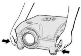
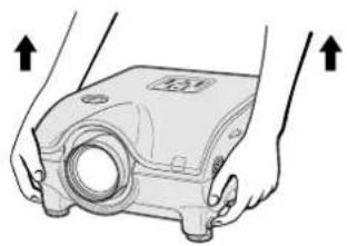
Illustration of hands holding a mechanical component with arrows indicating upward movement (no text or symbols)Press foot releases. Adjust height of projector and remove hands from foot releases.
3
natural_image
Technical line drawings of two mechanical components with mounting holes and directional arrows, labeled 'UP DOWN' (no text or symbols on the components themselves)Rotate feet to make minor changes.
NOTE
- The projector is adjustable up to approximately 10^ from the standard position.
- When the height of the projector is adjusted, the image may become distorted (keystoned), depending on the relative positions of the projector and the screen. See page 24 for keystone setting.
CAUTION
- Do not press the foot releases when the adjustment feet are extended without firmly holding the projector.
- Do not hold the lens when lifting or lowering the projector.
- When lowering the projector, be careful not to get your fingers caught in the area between the adjustment feet and the projector.

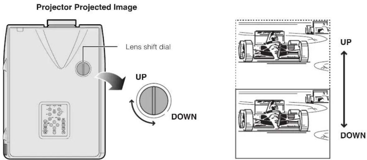
Using the Lens Shift
The picture can be adjusted within the shift range of the lens by rotating the dial on the top of the projector.
text_image
Projector Projected Image Lens shift dial UP DOWN UP DOWNNOTE
- The lens shift dial is set to the upper most position at the factory. Remember to adjust lower by turning the dial when operating the projector.
- The lens shift dial has two points to help orient the position. The center of the lens and bottom of the screen are the same height (10:0) and the center of the lens and center of the screen are the same height (5:5). When either position is reached by turning the dial, you will notice a slight latching feeling.
- Do not forcefully turn the lens shift dial beyond the 10:0 and 5:5 orientating positions; doing so may result in damaging the equipment.
- When the AN-P9MX of optional lens is attached, lens shift cannot be used.
Projector Remote control
text_image
POWER LAMP TEMP ON MUTE VOLUME OFF LENS MENU AUTO SYNC RESIZE GAMMA UNDO 12.3 INPUT 4.5 FREEZE BLACK SCREEN ENTER UNDO LENS UNDO ENTER OFF ON LENS MENU ▲/▼/◄► ENTER UNDO NLARGO FREEZE AUTO SYNC GAMA BLACK SCREEN T2 INPUT 9On-screen Display (Example: 4:3 NORMAL image)
natural_image
Black-and-white beach scene with palm trees, waves, and a shoreline (no text or symbols)↓
text_image
FOCUS NEW NEW NEW FOCUS↓
text_image
BZI ZOOM NEW BUY SELL↓
text_image
KEystone NEXT NEXT FINDS BLOOMY↓
text_image
V-Size 100 100 32.0007 NEXT VIEW NEWOn-screen Display (Example: 16:9 WIDE image)
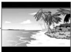
natural_image
Black-and-white illustration of a tropical beach scene with palm trees and waves (no text or symbols)↓
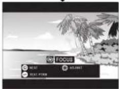
text_image
LOG FOCUS NEW CHANGE CHANGE FROM↓
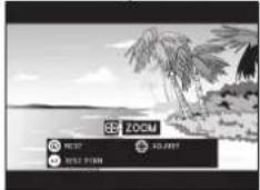
text_image
ZOOM NEW NEW FORM↓
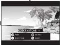
text_image
KEYSTONE NEW! NEW! NEW!↓
text_image
V-SIZE EXIT EXIT VIEW A3-0007 EXIT↓
text_image
DIGITAL SHIFT 0 FIND ADD RESET RESETDigital Image Adjustments
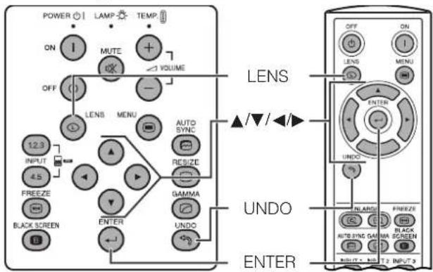
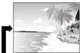
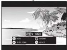
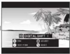
This function can be used to adjust the focus, zoom, keystone, v-size and digital shift settings.
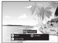
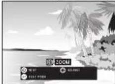
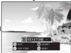
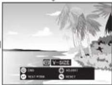
1 Press LENS to select mode. Each time LENS is pressed, the screen changes as shown on the left.
2 Press ENTER to display test pattern.
3 Press ▲/▼/◄/► to make adjustments.
4 a. Press LENS until normal screen appears.
b. To reset the "KEYSTONE", "V-SIZE" and "DIGITAL SHIFT" setting, press UNDO.
NOTE
- Do not touch the lens when adjusting the focus or zoom.
Keystone setting
Trapezoidal distortion is caused when the projector image is positioned away from the center axis of the screen. This function allows you to correct the keystone effect for excellent picture quality.
NOTE
- Straight lines and the edges of the displayed image may appear jagged, when adjusting the KEYSTONE setting.
V-size setting
During keystone correction an error can occur in the aspect ratio depending on the amount of lens shift. Use the V-SIZE fine-tuning function to correct this error.
NOTE
- V-SIZE is only displayed and can only be adjusted when performing KEYSTONE correction.
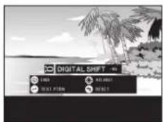
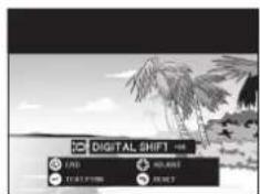
Digital shift setting
For easier viewing, this function shifts the image projected on the screen up or down eliminating either the upper or lower black band found in 16:9 and other wide aspect ratios.
NOTE
- Digital shift function only works with BORDER, STRETCH or SMART STRETCH of VIDEO and DTV inputs. (See page 35 for details.) The DIGITAL SHIFT screen is not displayed when projecting images other than WIDE.
Digital Shift
text_image
DIGITAL SHIFT 100% 100% 0.0007 100% 0.0008 100% 0.0009 100% 0.0010Press ▲. Press ▼.
or
text_image
DIGITAL SHIFT LND RGB JPEG JPEGPosition the projector perpendicular to the screen with all feet flat and level to achieve an optimal image. Move the projector forward or backward if the edges of the image are distorted.
NOTE
- The projector lens should be centered in the middle of the screen. If the lens center is not perpendicular to the screen, the image will be distorted, making viewing difficult.
- Position the screen so that it is not in direct sunlight or room light. Light falling directly onto the screen washes out colors, making viewing difficult. Close the curtains and dim the lights when setting up the screen in a sunny or bright room.
- A polarizing screen cannot be used with this projector.
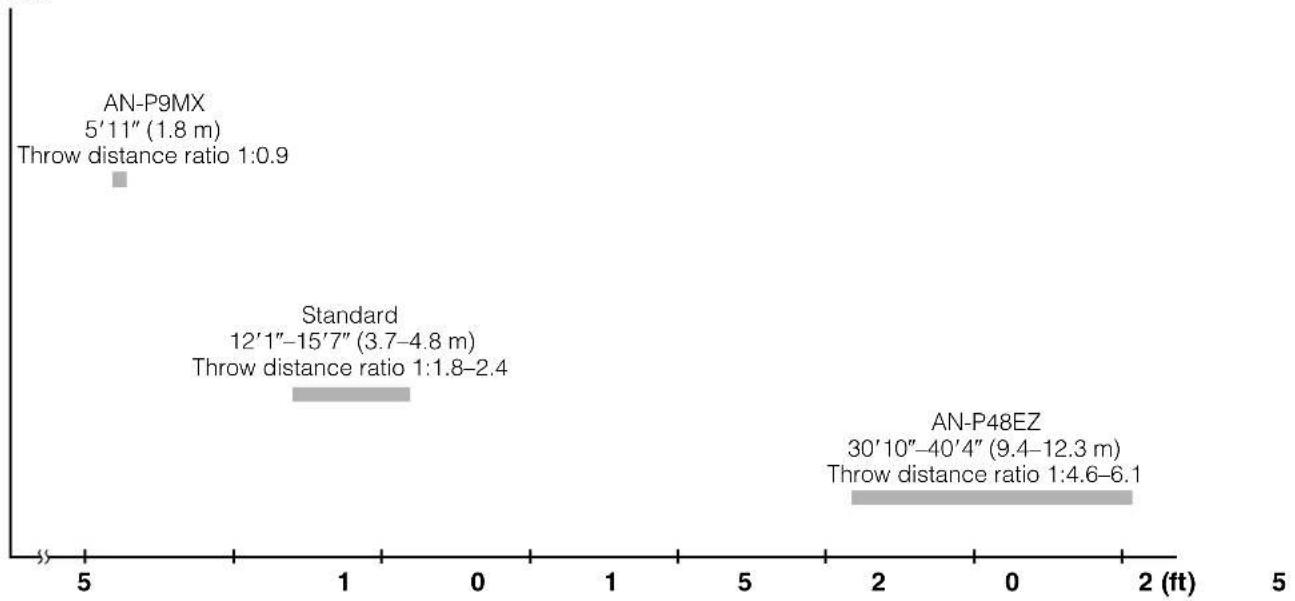
Two optional lenses from Sharp are also available for specialized application. Please see your local Sharp Authorized LCD Projector Dealer to details on all the lenses. (Refer to the lens operation manual when attaching a lens.) Also, be sure to have service personnel install the AN-P9MX and AN-P48EZ optional lenses.
Throw Distance
The graph below is for 100 inches (254 cm) screen with 4:3 normal mode.
Screen
bar
| Category | Throw distance ratio (ft) | Throw distance ratio (m) | | :--- | :--- | :--- | | AN-P9MX | 5'11" | 1.8 | | Standard | 12'1"-15'7" | 3.7-4.8 | | AN-P48EZ | 30'10"-40'4" | 9.4-12.3 | Throw distance ratio 1:4.6-6.1Standard Setup (Front Projection)
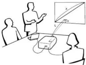
Place the projector at the required distance from the screen according to the desired picture size. (See pages 27 to 29.)
NOTE
- Two optional lenses from Sharp are available for specialized application. Please see your local Sharp Authorized LCD Projector Dealer for details on all the lenses.
text_image
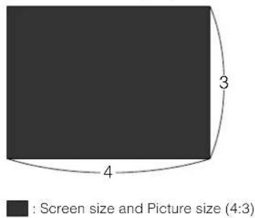
Diagram illustrating a medical or diagnostic procedure with labeled components and projection viewNORMAL Mode (4:3)
text_image
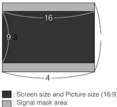
: Screen size and Picture size (4:3)STRETCH Mode (16:9)
text_image
Screen size and Picture size (16:9) Signal mask area 9 3 4 16Upper and Lower Lens Shift Position
- This projector is equipped with a lens shift function that lets you adjust the projection height.
- Adjust to match the setup configuration.
Screen size: 100 inches (254 cm)
STRETCH Mode: 16:9
Standard Lens as an example
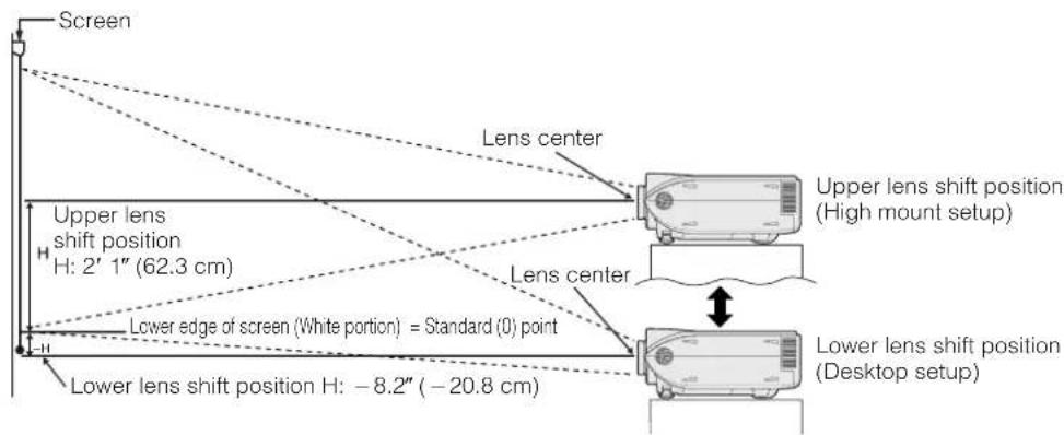
text_image
Screen Lens center Upper lens shift position H: 2' 1" (62.3 cm) Lower edge of screen (White portion) = Standard (0) point Lower lens shift position H: -8.2" (-20.8 cm) Upper lens shift position (High mount setup) Lens center Lower lens shift position (Desktop setup)Upper and Lower Lens Shift Position (Ceiling Mount)
When the projector is in the inverted position, use the upper edge of the screen as the base line, and exchange the lower and upper lens shift values.
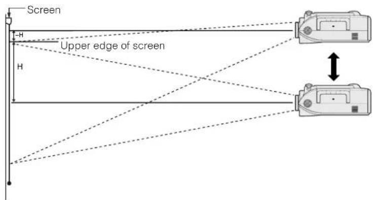
text_image
Screen H Upper edge of screen HNOTE
- Optimal image quality is produced with the projector positioned perpendicular to the screen with all feet flat and level. Tilting or angling the projector will reduce the effectiveness of the lens shift function.
Standard Lens
Throw distance ratio
1:1.8 to 2.4
NORMAL Mode (4:3)
| Screen size (4:3) (X) | Projection distance (L) | Lens center to the lower edge of the screen (H) | ||||
| Diag. Width | Height | Maximum (l) | Minimum (l) | Upper lens shift position (i1) | Lower lens shift position (i2) | |
| 300" (762 cm) | 240" (609.6 cm) | 180" (457.2 cm) | 48' 2" (14.7 m) | 37' 4" (11.4 m) | 7' 6" (228.6 cm) | 0.0"(0.0 cm) |
| 200" (508 cm) | 160" (406.4 cm) | 120" (304.8 cm) | 32' 2" (9.8 m) | 24' 6" (7.5 m) | 5' 0" (152.4 cm) | 0.0"(0.0 cm) |
| 150" (381 cm) | 120" (304.8 cm) | 90" (228.6 cm) | 24' 0" (7.3 m) | 18' 4" (5.6 m) | 3' 9" (114.3 cm) | 0.0"(0.0 cm) |
| 100" (254 cm) | 80" (203.2 cm) | 60" (152.4 cm) | 15' 7" (4.8 m) | 12' 1" (3.7 m) | 2' 6" (76.2 cm) | 0.0"(0.0 cm) |
| 84" (213.4 cm) | 67" (170.2 cm) | 50" (127 cm) | 13' 1" (4.0 m) | 10' 2" (3.1 m) | 2' 1" (64.0 cm) | 0.0"(0.0 cm) |
| 72" (182.9 cm) | 58" (147.3 cm) | 43" (109.2 cm) | 11' 2" (3.4 m) | 8' 5" (2.6 m) | 1' 10" (54.9 cm) | 0.0"(0.0 cm) |
| 60" (152.4 cm) | 48" (121.9 cm) | 36" (91.4 cm) | 9' 2" (2.8 m) | 7' 2" (2.2 m) | 1' 6" (45.7 cm) | 0.0"(0.0 cm) |
| 40" (101.6 cm) | 32" (81.3 cm) | 24" (61 cm) | 6' 2" (1.9 m) | 4' 6" (1.4 m) | 1' 0" (30.5 cm) | 0.0"(0.0 cm) |
The formula for screen size and projection distance
l, (Max.) = (0.0495x - 0.1302) × 3.28
x: Screen size (diag.) (X) (inches)
l_2 (Min.) = (0.0383x - 0.1153) × 3.28
l: Projection distance (L) (feet)
,(Upper)=0.3x
h: Lens center to the lower edge of the screen (H) (inches)
h_,(Lower) = 0
STRETCH Mode (16:9)
| Screen size (4:3) (X) | Projection distance (L) | Lens center to the lower edge of the screen (H) | ||||
| Diag. Width | Height | Maximum (L) | Minimum (L) | Upper lens shift position (k.) | Lower lens shift position (k.) | |
| 300" (762 cm) | 261" (662.9 cm) | 147" (373.4 cm) | 52' 5" (16.0 m) | 40' 7" (12.4 m) | 6' 2" (186.8 cm) | -2' 1" (-62.3 cm) |
| 200" (508 cm) | 174" (442 cm) | 98" (248.9 cm) | 34' 8" (10.6 m) | 26' 9" (8.2 m) | 4' 1" (124.5 cm) | -1' 4" (-41.5 cm) |
| 150" (381 cm) | 131" (332.7 cm) | 74" (188 cm) | 26' 2" (8.0 m) | 20' 3" (6.2 m) | 3' 1" (93.4 cm) | -1' 0" (-31.1 cm) |
| 133" (337.8 cm) | 116" (294.6 cm) | 65" (165.1 cm) | 23' 3" (7.1 m) | 17' 7" (5.4 m) | 2' 9" (82.8 cm) | -10.9" (-27.6 cm) |
| 106" (269.2 cm) | 92" (233.7 cm) | 52" (132.1 cm) | 18' 4" (5.6 m) | 14' 1" (4.3 m) | 2' 2" (66.0 cm) | -8.7" (-22.0 cm) |
| 100" (254 cm) | 87" (221 cm) | 49" (124.5 cm) | 17' 4" (5.3 m) | 13' 5" (4.1 m) | 2' 1" (62.3 cm) | -8.2" (-20.8 cm) |
| 92" (233.7 cm) | 80" (203.2 cm) | 45" (114.3 cm) | 15' 7" (4.8 m) | 12' 1" (3.7 m) | 1' 11" (57.3 cm) | -7.5" (-19.1 cm) |
| 84" (213.4 cm) | 73" (185.4 cm) | 41" (104.1 cm) | 14' 4" (4.4 m) | 11' 2" (3.4 m) | 1' 9" (52.3 cm) | -6.9" (-17.4 cm) |
| 72" (182.9 cm) | 63" (160 cm) | 35" (88.9 cm) | 12' 5" (3.8 m) | 9' 5" (2.9 m) | 1' 6" (44.8 cm) | -5.9" (-14.9 cm) |
| 60" (152.4 cm) | 52" (132.1 cm) | 29" (73.7 cm) | 10' 2" (3.1 m) | 7' 9" (2.4 m) | 1' 3" (37.4 cm) | -4.9" (-12.5 cm) |
| 40" (101.6 cm) | 35" (88.9 cm) | 20" (50.8 cm) | 6' 6" (2.0 m) | 5' 2" (1.6 m) | 9.8" (24.9 cm) | -3.3" (-8.3 cm) |
The formula for screen size and projection distance
l, (Max.) = (0.0538x - 0.1242) × 3.28
x: Screen size (diag.) (X) (inches)
I_2 (Min.) = (0.0417x - 0.1135) × 3.28
l: Projection distance (L) (feet)
_i(Upper) = 0.2451x
h: Lens center to the lower edge of the screen (H) (inches)
h_2(Lower) = -0.0817x
NOTE
• There is an error of ±3% in the formula above.
- Values with a minus (−) sign indicate the distance of the lens center below the bottom of the screen.
AN-P9MX
Throw distance ratio 1:0.9
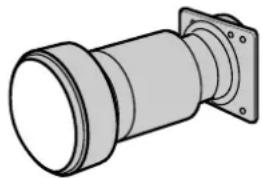
natural_image
Technical illustration of a cylindrical mechanical component with flanged ends and a central shaft (no text or symbols)NORMAL Mode (4:3)
| Screen size (4:3) (X) | Projection distance (L) | Lens center to the lower edge of the screen (H) | ||
| Diag. Width | Height | |||
| 300" (762 cm) | 240" (609.6 cm) | 180" (457.2 cm) | 18' 1" (5.5 m) | 7' 6" (228.6 cm) |
| 200" (508 cm) | 160" (406.4 cm) | 120" (304.8 cm) | 12' 0" (3.7 m) | 5' 0" (152.4 cm) |
| 150" (381 cm) | 120" (304.8 cm) | 90" (228.6 cm) | 9' 0" (2.7 m) | 3' 9" (114.3 cm) |
| 100" (254 cm) | 80" (203.2 cm) | 60" (152.4 cm) | 5' 11" (1.8 m) | 2' 6" (76.2 cm) |
| 84" (213.4 cm) | 67" (170.2 cm) | 50" (127 cm) | 4' 11" (1.5 m) | 2' 1" (64.0 cm) |
| 72" (182.9 cm) | 58" (147.3 cm) | 43" (109.2 cm) | 4' 2" (1.3 m) | 1' 10" (54.9 cm) |
| 60" (152.4 cm) | 48" (121.9 cm) | 36" (91.4 cm) | 3' 6" (1.1 m) | 1' 6" (45.7 cm) |
| 40" (101.6 cm) | 32" (81.3 cm) | 24" (61 cm) | 2' 3" (0.7 m) | 1' 0" (30.5 cm) |
The formula for screen size and projection distance
l = (0.0186x - 0.0563) × 3.28
h = 0.3x
x: Screen size (diag.) (X) (inches)
l: Projection distance (L) (feet)
h: Lens center to the lower edge of the screen (H) (inches)
STRETCH Mode (16:9)
| Screen size (4:3) (X) | Projection distance (L) | Lens center to the lower edge of the screen (H) | ||
| Diag. Width | Height | |||
| 300" (762 cm) | 261" (662.9 cm) | 147" (373.4 cm) | 19' 9" (6.0 m) | 6' 2" (186.8 cm) |
| 200" (508 cm) | 174" (442 cm) | 98" (248.9 cm) | 13' 2" (4.0 m) | 4' 1" (124.5 cm) |
| 150" (381 cm) | 131" (332.7 cm) | 74" (188 cm) | 9' 10" (3.0 m) | 3' 1" (93.4 cm) |
| 133" (337.8 cm) | 116" (294.6 cm) | 65" (165.1 cm) | 8' 8" (2.6 m) | 2' 9" (82.8 cm) |
| 106" (269.2 cm) | 92" (233.7 cm) | 52" (132.1 cm) | 6' 10" (2.1 m) | 2' 2" (66.0 cm) |
| 100" (254 cm) | 87" (221 cm) | 49" (124.5 cm) | 6' 6" (2.0 m) | 2' 1" (62.3 cm) |
| 92" (233.7 cm) | 80" (203.2 cm) | 45" (114.3 cm) | 5' 11" (1.8 m) | 1' 11" (57.3 cm) |
| 84" (213.4 cm) | 73" (185.4 cm) | 41" (104.1 cm) | 5' 4" (1.6 m) | 1' 9" (52.3 cm) |
| 72" (182.9 cm) | 63" (160 cm) | 35" (88.9 cm) | 4' 8" (1.4 m) | 1' 6" (44.8 cm) |
| 60" (152.4 cm) | 52" (132.1 cm) | 29" (73.7 cm) | 3' 9" (1.2 m) | 1' 3" (37.4 cm) |
| 40" (101.6 cm) | 35" (88.9 cm) | 20" (50.8 cm) | 2' 6" (0.8 m) | 10.0" (24.9 cm) |
The formula for screen size and projection distance
l = (0.0203x - 0.0579) × 3.28
h = 0.2451x
x: Screen size (diag.) (X) (inches)
I: Projection distance (L) (feet)
h: Lens center to the lower edge of the screen (H) (inches)
NOTE
- There is an error of ± 3% in the formula above.
- Values with a minus (−) sign indicate the distance of the lens center below the bottom of the screen.
AN-P48EZ
Throw distance ratio
1:4.6 to 6.1
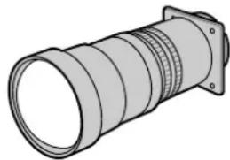
natural_image
Illustration of a cylindrical mechanical component with flanged ends and threaded sections (no text or symbols)NORMAL Mode (4:3)
| Screen size (4:3) (X) | Projection distance (L) | Lens center to the lower edge of the screen (H) | ||||
| Diag. Width | Height | Maximum (l) | Minimum (l) | Upper lens shift position (k) | Lower lens shift position (k) | |
| 300" (762 cm) | 240" (609.6 cm) | 180" (457.2 cm) | 119' 9" (36.5 m) | 91' 6" (27.9 m) | 7' 6" (228.6 cm) | 0.0" (0.0 cm) |
| 200" (508 cm) | 160" (406.4 cm) | 120" (304.8 cm) | 80' 1" (24.4 m) | 61' 4" (18.7 m) | 5' 0" (152.4 cm) | 0.0" (0.0 cm) |
| 150" (381 cm) | 120" (304.8 cm) | 90" (228.6 cm) | 60' 0" (18.3 m) | 45' 11" (14.0 m) | 3' 9" (114.3 cm) | 0.0" (0.0 cm) |
| 100" (254 cm) | 80" (203.2 cm) | 60" (152.4 cm) | 40' 4" (12.3 m) | 30' 10" (9.4 m) | 2' 6" (76.2 cm) | 0.0" (0.0 cm) |
| 84" (213.4 cm) | 67" (170.2 cm) | 50" (127 cm) | 33' 10" (10.3 m) | 25' 11" (7.9 m) | 2' 1" (64.0 cm) | 0.0" (0.0 cm) |
| 72" (182.9 cm) | 58" (147.3 cm) | 43" (109.2 cm) | 29' 2" (8.9 m) | 22' 4" (6.8 m) | 1' 10" (54.9 cm) | 0.0" (0.0 cm) |
| 60" (152.4 cm) | 48" (121.9 cm) | 36" (91.4 cm) | 24' 3" (7.4 m) | 18' 8" (5.7 m) | 1' 6" (45.7 cm) | 0.0" (0.0 cm) |
The formula for screen size and projection distance
l_i(Max.) = (0.1214x + 0.1272) × 3.28
x: Screen size (diag.) (X) (inches)
I_· (Min.) = (0.0927x + 0.1233)× 3.28
I: Projection distance (L) (feet)
h_i(Upper) = 0.3x
h: Lens center to the lower edge of the screen (H) (inches)
h_2(Lower) = 0
STRETCH Mode (16:9)
| Screen size (4:3) (X) | Projection distance (L) | Lens center to the lower edge of the screen (H) | ||||
| Diag. Width | Height | Maximum (L) | Minimum (L) | Upper lens shift position (h) | Lower lens shift position (h) | |
| 300" (762 cm) | 261" (662.9 cm) | 147" (373.4 cm) | 130' 7" (39.8 m) | 99' 9" (30.4 m) | 6' 2" (186.8 cm) | -2' 1" (-62.3 cm) |
| 200" (508 cm) | 174" (442 cm) | 98" (248.9 cm) | 87' 3" (26.6 m) | 66' 7" (20.3 m) | 4' 1" (124.5 cm) | -1' 4" (-41.5 cm) |
| 150" (381 cm) | 131" (332.7 cm) | 74" (188 cm) | 65' 7" (20.0 m) | 50' 2" (15.3 m) | 3' 1" (93.4 cm) | -1' 0" (-31.1 cm) |
| 133" (337.8 cm) | 116" (294.6 cm) | 65" (165.1 cm) | 58' 1" (17.7 m) | 44' 7" (13.6 m) | 2' 9" (82.8 cm) | -10.9" (-27.6 cm) |
| 106" (269.2 cm) | 92" (233.7 cm) | 52" (132.1 cm) | 46' 3" (14.1 m) | 35' 5" (10.8 m) | 2' 2" (66.0 cm) | -8.7" (-22.0 cm) |
| 100" (254 cm) | 87" (221 cm) | 49" (124.5 cm) | 44' 0" (13.4 m) | 33' 6" (10.2 m) | 2' 1" (62.3 cm) | -8.2" (-20.8 cm) |
| 92" (233.7 cm) | 80" (203.2 cm) | 45" (114.3 cm) | 40' 4" (12.3 m) | 30' 10" (9.4 m) | 1' 11" (57.3 cm) | -7.5" (-19.1 cm) |
| 84" (213.4 cm) | 73" (185.4 cm) | 41" (104.1 cm) | 36' 9" (11.2 m) | 28' 3" (8.6 m) | 1' 9" (52.3 cm) | -6.9" (-17.4 cm) |
| 72" (182.9 cm) | 63" (160 cm) | 35" (88.9 cm) | 31' 10" (9.7 m) | 24' 3" (7.4 m) | 1' 6" (44.8 cm) | -5.9" (-14.9 cm) |
| 60" (152.4 cm) | 52" (132.1 cm) | 29" (73.7 cm) | 26' 7" (8.1 m) | 20' 4" (6.2 m) | 1' 3" (37.4 cm) | -4.9" (-12.5 cm) |
The formula for screen size and projection distance
I_1(Max.) = (0.1323x + 0.1272) × 3.28
x: Screen size (diag.) (X) (inches)
I_2 (Min.) = (0.101x + 0.1233) × 3.28
l: Projection distance (L) (feet)
h_i(Upper) = 0.2451x
h: Lens center to the lower edge of the screen (H) (inches)
h_2 (Lower) = -0.0817x
NOTE
• There is an error of ±3% in the formula above.
- Values with a minus (−) sign indicate the distance of the lens center below the bottom of the screen.

Rear Projection
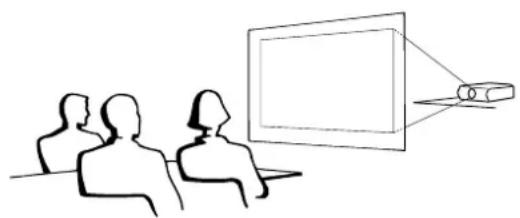
natural_image
Line drawing of three people watching a projector screen (no text or symbols)- Place a translucent screen between the projector and the audience.
- Use the projector's menu system to reverse the projected image. (See page 51 for use of this function.)
NOTE
- Optimal image quality can be achieved when the projector is positioned perpendicular to the screen with all feet flat and level.

Projection Using a Mirror
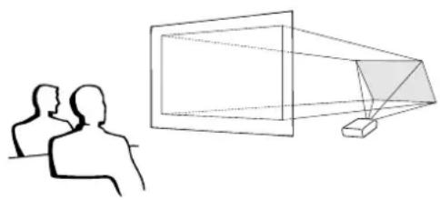
natural_image
Simple line drawing of two human silhouettes facing a screen and projecting a geometric shape (no text or symbols)- When the distance between the projector and screen is not sufficient for normal rear projection, you can use a mirror to reflect the image onto the screen.
- Place a mirror (normal flat type) in front of the lens.
- Project the normal image onto the mirror.
- The image reflected from the mirror is projected onto the translucent screen.
CAUTION
- When using a mirror, be sure to carefully position both the projector and the mirror so the light does not shine into the eyes of the audience.

Ceiling-mount Projection
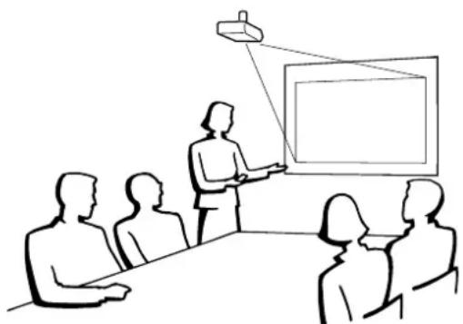
natural_image
Line drawing of a meeting scene with a presenter and audience (no text or symbols)- It is recommended that you use the optional Sharp ceiling-mount bracket for this installation.
- Before mounting the projector, contact your nearest Sharp Authorized LCD Projector Dealer or Service Center to obtain the recommended ceiling-mount bracket (sold separately). (AN-XGCM61 ceiling-mount bracket and its AN-EP101AP extension tube (for U.S.A.), or AN-NV6T ceiling-mount bracket and its AN-TK201/AN-TK202 extension tubes (for countries other than the U.S.A.))
- When the projector is in the inverted position, use the upper edge of the screen as the base line.
- Use the projector's menu system to select the appropriate projection mode. (See page 51 for use of this function.)

Selecting the Input Signal Source
Projector Remote control
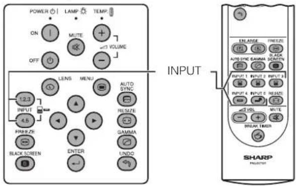
text_image
POWER ON OFF LAMP MUTE VOLUME LENS MENU AUTO SYNC INPUT 4.5 FREEZE BLACK SCREEN ENTER UNDO INPUT 12.3 RESETZE GAMMA INPUT 2 INPUT 3 INPUT 4 INPUT 5 RESET 1 VOLT + - BREAK TIMER INPUT SHARP INPUT ENLARGE FREEZE F1 F2 F3 AUTO SYNC GAMMA SCREEN OUTPUT 1 INPUT 2 INPUT 3 OUTPUT 4 INPUT 5 RESET 1 VOLT + - BREAK TIMERPress INPUT 1.2.3 or INPUT 4.5 on the projector or INPUT (1, 2, 3, 4 or 5) on the remote control to change the mode.
NOTE
- When no signal is received, "NO SIGNAL" will be displayed. When a signal that the projector is not preset to receive is received, "NOT REG." will be displayed.
On-screen Display
INPUT 1 Mode INPUT 2 Mode INPUT 3 Mode

INPUT 4 Mode INPUT 5 Mode


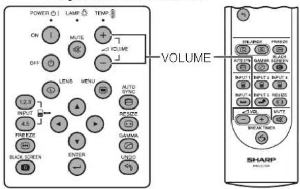
Adjusting the Volume
Projector Remote control
text_image
POWER ON OFF LAMP MUTE VOLUME LENS MENU AUTO SYNC RESIZE GAMMA BLACK SCREEN 12.3 INPUT 4.5 FREEZE BLACK SCREEN ENTER UNDO VOLUME ENLARGE FREEZE MAX 300 MHz GAMMA SCREEN INPUT 1 INPUT 2 INPUT 3 INPUT 4 INPUT 5 RESET VOL MUTE BREAK TIMER SHARPPress VOLUME -/+ to adjust the volume.
On-screen Display
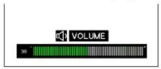
text_image
VOLUME 30
Muting the Sound
Projector
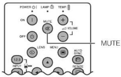
text_image
POWER | LAMP | TEMP | ON | MUTE + OFF | VOLUME - LENS MENU AUTO SYNC RESIZE 12.3 INPUT E MUTERemote control
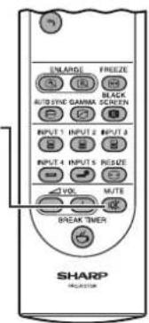
text_image
ENLARGE FREEZE A1 B2 BLACK RUTYING GAMMA SCREEN INPUT 1 INPUT 2 INPUT 3 INPUT 4 INPUT 5 RESET VOL MUTE BREAK TIMER SHARP RELATORPress MUTE to temporarily turn off the sound.
Press MUTE again to turn the sound back on.
On-screen Display
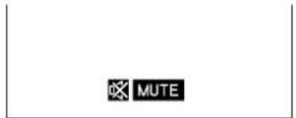
text_image
MUTE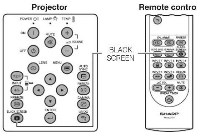
text_image
Projector POWER LAMP TEMP ON MUTE VOLUME OFF LENS MENU AUTO INPUT RESUZB 4.5 GAMA FREEZE BLACK SCREEN ENTER UNDO BLACK SCREEN Remote control ENLARGE FREEZE AUTO SING GAMMA SCREEN INPUT 1 INPUT 2 INPUT 3 INPUT 4 INPUT 5 RESET VOL MUTE BREAK TIMER SHARP PRODUCER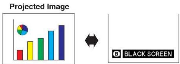
bar
| Color | Projected Image | |---|---| | Red | 1.5 | | Yellow | 2.5 | | Green | 3.0 | | Blue | 4.0 | | Dark Blue | 5.0 |This function can be used to superimpose a black screen over the projected image.
Blacking out the Projected Image
Press BLACK SCREEN. The screen turns black and "BLACK SCREEN" is displayed on the screen. To return to the original projected image, press BLACK SCREEN again.

Displaying a Still Image
text_image
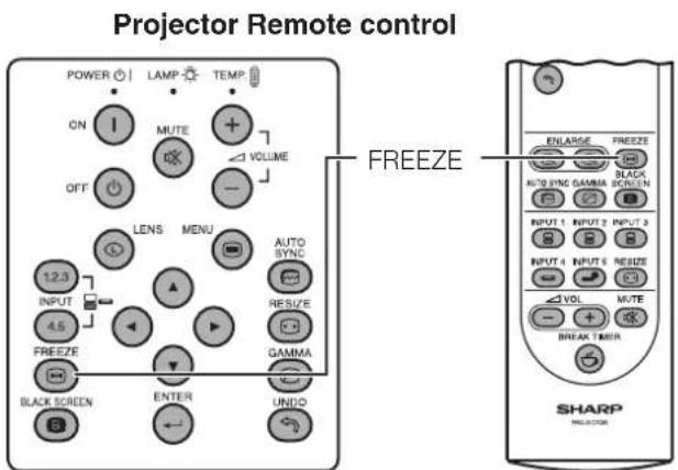
Projector Remote control POWER | LAMP | TEMP | ON | MUTE VOLUME OFF LENS MENU AUTO SYNC INPUT 1.2.3 + 4.5 FREEZE RESIZE BLACK SCREEN GAMA ENTER UNDO FREEZE ENLARGE FREEZE AUTO SYNC GAMMA BLACK SCREEN INPUT 1 INPUT 2 INPUT 3 INPUT 4 INPUT 5 RESIZE VOL MUTE BREAK TIMER SHARPThis function allows you to instantly freeze a moving image. This is useful when you want to display a still image from a computer or video, giving you more time to explain the image to the audience.
You can also use this function to display a still image from a computer while you make preparations for the next computer images to be presented.
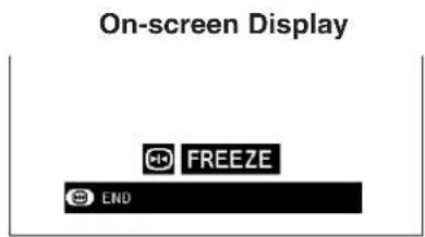
1 Press FREEZE to freeze the image.
2 Press FREEZE again to return to the moving image.
text_image
On-screen Display FREEZE ENDRemote control
text_image
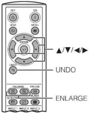
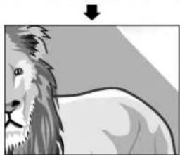
OFF ON I LENS MENU ENTER UNDO UNDO ENLARGE FREEZE AUTO FND BLACK INPUT 1 INPUT 2 INPUT 3 ▲/▼/◄► ENLARGEThis function allows you to magnify a specific portion of an image. This is useful when you want to display a detailed portion of the image.
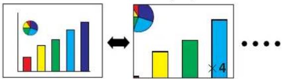
1 Press ENLARGE (☐) to zoom in. (Press ENLARGE (☐) to zoom out.) ×1←→×4←→×9←→×16←→×36←→×64
2 To return to ×1, press UNDO.
NOTE
- If you press ENLARGE (Q) when the zoom is set to ×1, no change will occur. And if you press ENLARGE (Q) when the zoom is set to ×64, no change will occur.
- If the input signal is changed during digital image magnification, the image will return to × 1 . The input signal is changed
(a) when INPUT 1, 2, 3, 4 or 5 is pressed,
(b) when the input signal is interrupted, or
(c) when the input resolution and refresh rate changes.
(a) when INPUT 1, 2, 3, 4 or 5 is pressed, (b) when the input signal is interrupted, or (c) when the input resolution and refresh rate changes.
On-screen Display
bar
| Category | Value | |---|---| | Bar 1 | 3 | | Bar 2 | 6 | | Bar 3 | 8 | | Bar 4 | 10 | | Bar 5 | 12 | | Bar 6 | 14 | | Bar 7 | 16 | | Bar 8 | 18 | | Bar 9 | 20 | | Bar 10 | 22 | All three bars are equal in height (indicated by ×4). The chart visually represents a comparison of values between two groups: one group (red circle) and another (blue circle).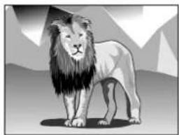
natural_image
Illustration of a standing lion with long mane and mountain background (no text or symbols)Press ENLARGE (☐) to zoom in.
natural_image
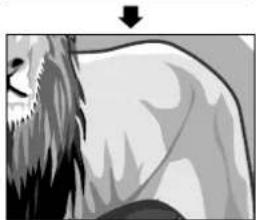
Illustration of a lion's head and neck with a downward arrow, no text or symbols presentPress ▲/▼/◄/►.
natural_image
Illustration of a lion with a long mane and spiky mane, no text or symbols present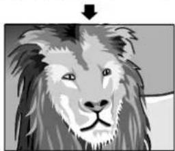
natural_image
Illustration of a lion's head with a pointing arrow (no text or symbols)Pan Around the Screen
Enlarging the screen image and move it around.
When the image is magnified, press ▲/▼/◄/► to pan and scan around the image.
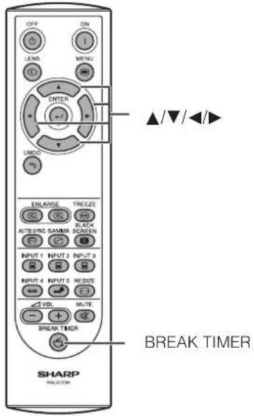
Remote control This function can be used to show the remaining time for break during meeting.
text_image
OFF ON LENS MENU ENTER UNDO ENLARGE FREEZE AUTO SING GAVM BLACK SCREEN INPUT 1 INPUT 2 INPUT 3 INPUT 4 INPUT 5 RESET VOL MUTE BREAK TIMER BREAK TIMER SHARP PROJECTOR1 Press BREAK TIMER. The timer starts to count down from 5 minutes.
- You can set the Break Timer 1 to 60 minutes with ▲/▼/
◀/▶. The timer starts to count down as soon as ▲/▼/
◀/▶ is pressed.
2 Press BREAK TIMER to cancel the Break Timer.
NOTE
- The Break Timer is displayed against the background image selected in "Selecting a Startup Image." (See page 49)
On-screen Display
5:00

Computer Image Adjustments using AUTO SYNC
Projector Remote control
text_image
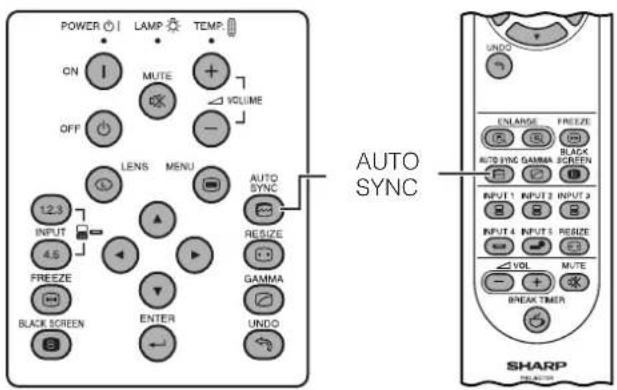
POWER ON OFF 12.3 INPUT 4.5 FREEZE BLACK SCREEN LAMP MUTE VOLUME LENS MENU AUTO SYNC RESIZE GAMMA ENTER UNDO AUTO SYNC ENLARGE FREEZE AUTO SYNC GAMA SCREEN INPUT 1 INPUT 2 INPUT 3 INPUT 4 INPUT 5 RESET VOL MUTE BREAK TIMER SHARPThis function can be used to automatically adjust a computer image.
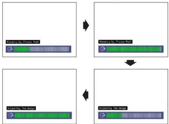
Press AUTO SYNC. During Auto Sync adjustment, the On-screen Display changes as shown on the bottom left.
- See page 45 "Auto Sync Adjustment" for setting the Auto Sync.
NOTE
- Auto Sync adjustment may take some time to complete, depending on the image of the computer connected to the projector.
On-screen Display
flowchart
graph TD
    A["Warming Up, Please Wait"] --> B["Warming Up, Please Wait"]
    B --> C["Adjusting The Image"]
    C --> D["Adjusting The Image"]
Projector
text_image
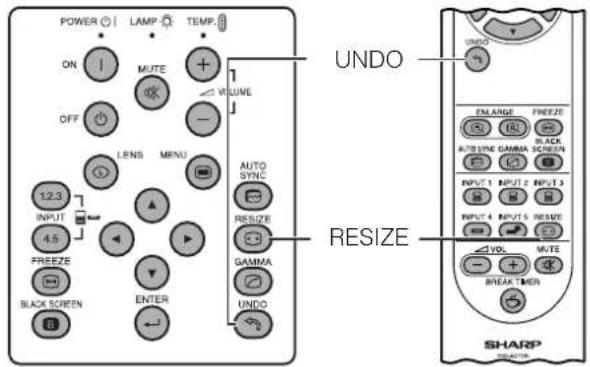
POWER LAMP TEMP ON MUTE + OFF LRNS MENU 12.3 INPUT 4.5 FREEZE BLACK SCREEN ENTER AUTO SYNC RESIZE GAMMA UNDO UNDO ENLARGE FREEZE AUTO SYNC GAMMA SCREEN INPUT 1 INPUT 2 INPUT 3 INPUT 4 INPUT 5 RESET VOL MUTE BREAK MUN RESIZE SHARPThis function allows you to modify or customize the picture display mode to enhance the input image. Depending on the input signal, you can choose NORMAL, FULL, DOT BY DOT, BORDER, STRETCH or SMART STRETCH image.
1 Press RESIZE. Each time RESIZE is pressed, the picture mode changes as shown below.
2 To return to the standard image, press UNDO while "RESIZE" is displayed on the screen.
COMPUTER
| NORMAL | FULL | DOT BY DOT | ||
| 4:3 aspect ratio | SVGA (800 × 600) | 1024 × 768 | - | 800 × 600 |
| XGA (1024 × 768) | 1024 × 768 | - | - | |
| SXGA (1280 × 960) | 1024 × 768 | - | 1280 × 960 | |
| UXGA (1600 × 1200) | 1024 × 768 | - | 1600 × 1200 | |
| Other aspect ratios | SXGA (1280 × 1024) | 960 × 768 | 1024 × 768 | 1280 × 1024 |
- "NORMAL" is fixed when XGA (1024 × 768) signals are entered.
| Input Signal | Output screen image | |||
| NORMALProjects a full screen image while maintaining the aspect ratio. | FULLProjects a full screen image while ignoring the aspect ratio. | DOT BY DOTProjects the original resolution signal of the image. | ||
| Resolution lower than XGA |  4:3 aspect ratio 4:3 aspect ratio |  | — | 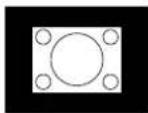 |
| XGA | 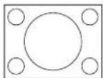 4:3 aspect ratio 4:3 aspect ratio | 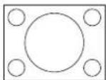 | — | — |
| Resolution higher than XGA | 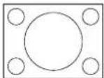 4:3 aspect ratio 4:3 aspect ratio | 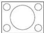 | — | 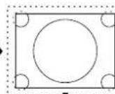 |
| SXGA(1280 × 1024) | 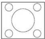 | 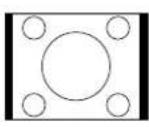 | → |   |
VIDEO
| NORMAL BOR | DER STRETCH SMART STRETCH | |||
| 480I, 480P, 580I, 580P, NTSC, PAL, SECAM | 4:3 aspect ratioLetter box, squeeze | 1024 × 768 768 × 576* | 1024 × 576* | 1024 × 576* |
| 720P, 1035I, 1080I | 16:9 aspect ratio | - | - | - |
- "STRETCH" is fixed when 720P, 1035I or 1080I signals are entered.
* The Digital Shift function can be used with these images.
| Input Signal | Output screen image | ||||
| NORMALProjects a full screen image. | BORDERProjects 4:3 image fully in STRETCH (the following column) image. | STRETCHProjects 16:9 image evenly over entire screen (top/bottom black bands). | SMART STRETCHProjects the image fully in a 16:9 screen by enlarging only the surrounding areas while keeping the aspect ratio in the middle part of the image at 4:3. | ||
| 480I, 480P, 580I, 580P, NTSC, PAL, SECAM |  4:3 aspect ratio 4:3 aspect ratio | 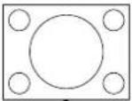 | 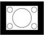 | 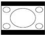 | 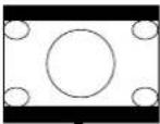 |
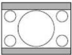 Letter box Letter box | 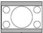 | 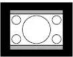 | 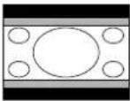 | 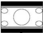 | |
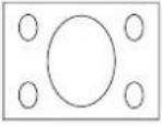 Squeeze Squeeze | 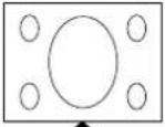 | 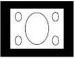 | 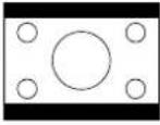 | 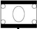 | |
| 720P, 1035 I, 1080I | 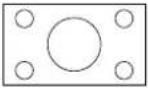 16:9 aspect ratio 16:9 aspect ratio | — | — | 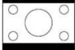 | — |
Projector • Gamma is an Remote Control hancement function
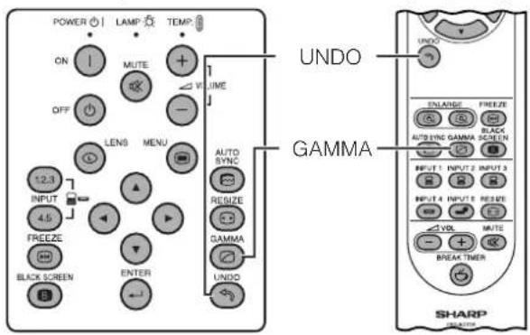
text_image
POWER ON OFF 12.3 INPUT 4.5 FREEZE BLACK SCREEN LAMP MUTE LENS MENU VOLUME AUTO SYNC RESET GAMMA UNDO UNDO ENLARGE FREEZE AUTO SYNC GAMMA SCREEN INPUT 1 INPUT 2 INPUT 3 INPUT 4 INPUT 5 RESET VDL MUTE BREAK TIMER GAMMA SHARP
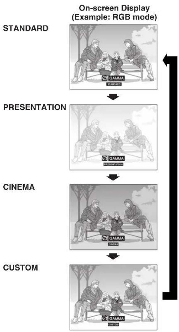
flowchart
graph TD
    A["STANDARD"] --> B["PRESENTATION"]
    B --> C["CINEMA"]
    C --> D["CUSTOM"]
    style A fill:#f9f,stroke:#333
    style B fill:#f9f,stroke:#333
    style C fill:#f9f,stroke:#333
    style D fill:#f9f,stroke:#333
that offers a richer image by brightening the darker portions of the image without altering the brightness of the brighter portions.
- Four gamma settings are available to allow for differences in the images displayed and in the brightness of the room.
- When you are displaying images with frequent, dark scenes, such as a film or concert, or when you are displaying images in a bright room, this feature makes the dark scenes easier to see and gives the impression of greater depth in the image.
Gamma Modes
| Gamma modeSelected Mode | |
| STANDARD | Standard picture without gamma correction. |
| PRESENTATION | Brightens darker portions of image for more enhanced presentations. |
| CINEMA | Gives greater depth to darker portions of image for a more exciting theater experience. |
| CUSTOM | Allows you to adjust gamma value using Sharp Advanced Presentation Software. |
1 Press GAMMA. Each time GAMMA is pressed, the gamma level toggles as shown on the left.
2 To return to the standard image, press UNDO while "GAMMA" is displayed on the screen.
NOTE
- The CUSTOM setting of VIDEO mode optimizes the video source to reproduce the image more beautifully. It darkens bright portions of the image and gives greater depth to darker portions of the image. Select CUSTOM as your default setting if you prefer a smooth textured image to a sharply contrasted one.
- STANDARD and CINEMA settings of VIDEO mode (except COMPONENT 480P/580P/720P/1035I/1080I) incorporate a DYNAMIC GAMMA function for optimizing GAMMA correction frame by frame in real time, thus providing a more beautiful image.
- PRESENTATION settings are the same for both RGB and VIDEO modes.

Basic Operations
This projector has two sets of menu screens that allow you to adjust the image and various projector settings. These menu screens can be operated from the projector or the remote control with the following procedure.
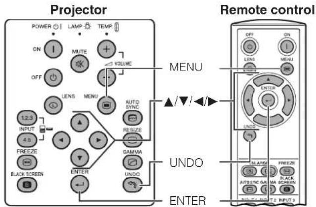
text_image
Projector POWER LAMP TEMP ON MUTE VOLUME OFF LENS MENU AUTO INPUT AUTO SYNC 4.5 FREEZE RESIZE BLACK SCREEN DAMMA UNDO ENTER MENU UNDO ENTER Remote control OFF ON LENS MENU ▲/▼/◄► ENTER UNDO N.A.MU FREEZE AUTO SYNC GA BLACK SCREEN INPUT 3(GUI) On-screen Display
INPUT 1, 2 (RGB) or 3 (DIGITAL) mode (Example)
1
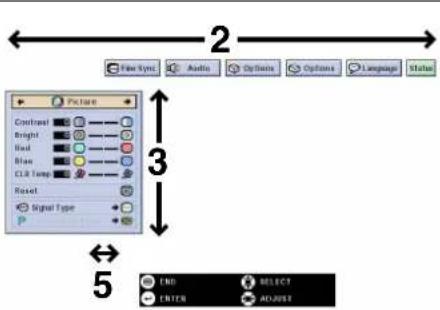
text_image
2 Picture Contrast Bright Red Blue CLR Temp Reset Signal Type 5 END SELECT ENTER ALABET4
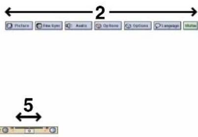
text_image
Picture Fox Icon Audio Options Options Language Status 2 5INPUT 4, 5 (VIDEO) mode (Example)
1
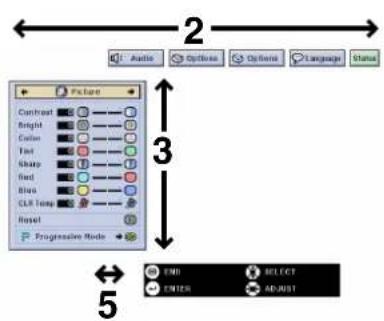
text_image
Audio Options Options Language Status 2 3 5 Picture Contrast Bright Color Tint Sharp Red Blue CLR Temp Reset Progressive Mode END SELECT ENTER ADJUST1 Press MENU to display the INPUT 1, 2, 3, 4 or 5 mode menu bar.
2 Press ◀/▶ to select an adjustment menu on the menu bar.
3 Press ▲/▼ to select a specific adjustment item.
4 To display a single adjustment item, press ENTER after selecting the item. Only the menu bar and the selected adjustment item will appear.
5 Press ◀/▶ to adjust the item.
6 Press UNDO to return to the previous screen.
7 To exit from the GUI, press MENU.
NOTE
- For details on items on the menu screen, see the tree charts on pages 39 and 40.
Items on the INPUT 1, 2 or 3 Mode Menu Bar
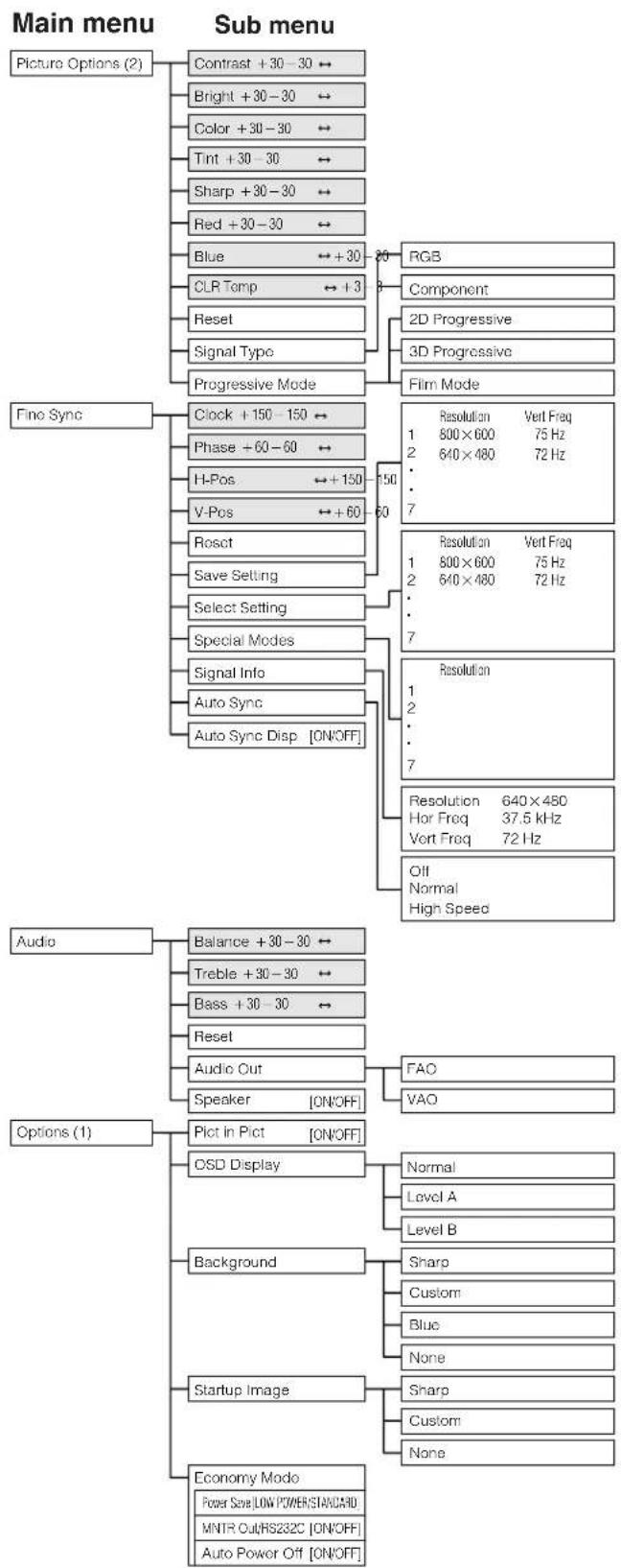
flowchart
graph TD
    A["Main menu"] --> B["Picture Options (2)"]
    B --> C1["Contrast +30-30 ↔"]
    B --> C2["Bright +30-30 ↔"]
    B --> C3["Color +30-30 ↔"]
    B --> C4["Tint +30-30 ↔"]
    B --> C5["Sharp +30-30 ↔"]
    B --> C6["Red +30-30 ↔"]
    B --> C7["Blue ↔+30"]
    C7 --> D1["RGB"]
    C7 --> D2["Component"]
    C7 --> D3["2D Progressive"]
    C7 --> D4["3D Progressive"]
    C7 --> D5["Film Mode"]

    A --> E1["Fine Sync"]
    E1 --> F1["Clock +150-150 ↔"]
    E1 --> F2["Phase +60-60 ↔"]
    E1 --> F3["H-Pos ↔+150"]
    E1 --> F4["V-Pos ↔+60"]
    E1 --> F5["Rosct"]
    E1 --> F6["Save Setting"]
    E1 --> F7["Select Setting"]
    E1 --> F8["Special Modes"]
    E1 --> F9["Signal Info"]
    E1 --> F10["Auto Sync"]
    E1 --> F11["Auto Sync Disp [ON/OFF"]]

    A --> G1["Audio"]
    G1 --> H1["Balance +30-30 ↔"]
    G1 --> H2["Treble +30-30 ↔"]
    G1 --> H3["Bass +30-30 ↔"]
    G1 --> H4["Reset"]
    G1 --> H5["Audio Out"]
    G1 --> H6["Speaker [ON/OFF"]]

    A --> I1["Options (1)"]
    I1 --> J1["Pict in Plot [ON/OFF"]]
    I1 --> J2["OSD Display"]
    I1 --> J3["Background"]
    I1 --> J4["Startup Image"]
    I1 --> J5["Economy Modo"]

    style A fill:#f9f,stroke:#333
    style B fill:#ccf,stroke:#333
    style E1 fill:#cfc,stroke:#333
    style G1 fill:#fcc,stroke:#333
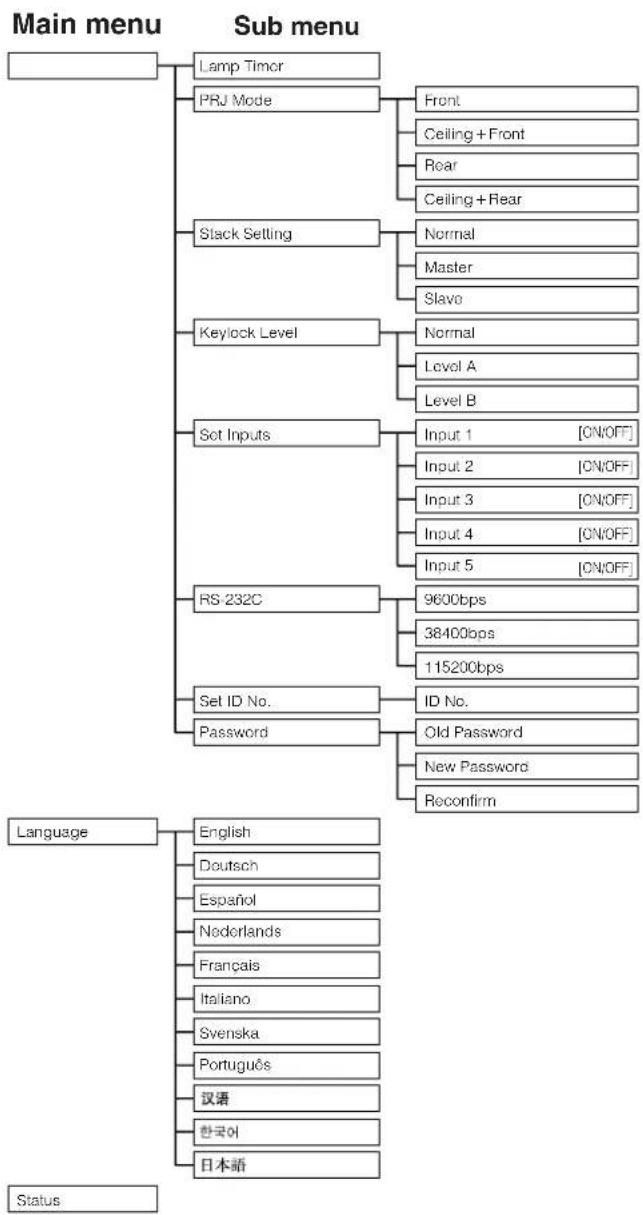
flowchart
graph TD
    A["Main menu"] --> B["Lamp Timor"]
    A --> C["PRJ Mode"]
    C --> D["Front"]
    C --> E["Ceiling + Front"]
    C --> F["Rear"]
    C --> G["Ceiling + Rear"]
    A --> H["Slack Setting"]
    H --> I["Normal"]
    H --> J["Master"]
    H --> K["Slavo"]
    A --> L["Keylock Level"]
    L --> M["Normal"]
    L --> N["Level A"]
    L --> O["Level B"]
    A --> P["Set Inputs"]
    P --> Q["Input 1 [ON/OFF"]]
    P --> R["Input 2 [ON/OFF"]]
    P --> S["Input 3 [ON/OFF"]]
    P --> T["Input 4 [ON/OFF"]]
    P --> U["Input 5 [ON/OFF"]]
    A --> V["RS-232C"]
    V --> W["9600bps"]
    V --> X["38400bps"]
    V --> Y["115200bps"]
    A --> Z["Set ID No."]
    Z --> AA["ID No."]
    Z --> AB["Password"]
    AB --> AC["Old Password"]
    AB --> AD["New Password"]
    AB --> AE["Reconfirm"]

    AF["Language"] --> AG["English"]
    AF --> AH["Deutsch"]
    AF --> AI["Espanol"]
    AF --> AJ["Nederlands"]
    AF --> AK["Français"]
    AF --> AL["Italiano"]
    AF --> AM["Svenska"]
    AF --> AN["Português"]
    AF --> AO["汉语"]
    AF --> AP["한국어"]
    AF --> AQ["日本語"]

    AR["Status"] --> AS
NOTE
- The resolution, vertical frequency and horizontal frequency figures displayed above are for example purposes only.
- "Color", "Tint", and "Sharp" appear only when Component input is selected in INPUT 1 or 2 mode. For INPUT 3 (DVI), in "Picture" menu, only "CLR Temp" is active and the other menus are displayed in gray. In "Fine Sync" menu, only "Signal Info" is active and the other menus are displayed in gray.
- Only the items highlighted in the tree charts above can be adjusted.
- To adjust the items under the sub menu, press ▶ after selecting the sub menu.
Items on the INPUT 4 or 5 Mode Menu Bar
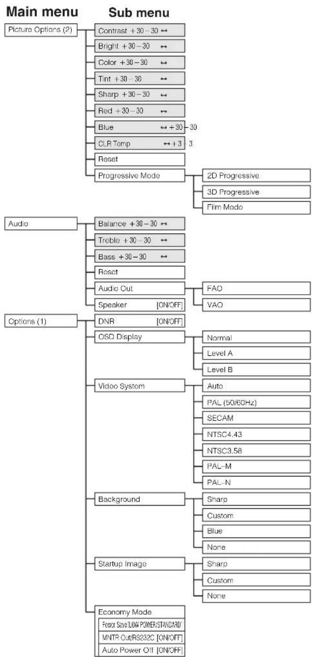
flowchart
graph TD
    A["Main menu"] --> B["Picture Options (2)"]
    A --> C["Sub menu"]
    B --> D["Contrast +30-30 ↔"]
    B --> E["Bright +30-30 ↔"]
    B --> F["Color +30-30 ↔"]
    B --> G["Tint +30-30 ↔"]
    B --> H["Sharp +30-30 ↔"]
    B --> I["Red +30-30 ↔"]
    B --> J["Blue ↔ +30-30"]
    B --> K["CLR Temp ↔ +3 3"]
    B --> L["Reset"]
    B --> M["Progressive Mode"]
    C --> N["2D Progressive"]
    C --> O["3D Progressive"]
    C --> P["Film Mode"]
    Q["Audio"] --> R["Balance +30-30 ↔"]
    Q --> S["Treble +30-30 ↔"]
    Q --> T["Bass +30-30 ↔"]
    Q --> U["Reset"]
    Q --> V["Audio Out"]
    V --> W["Speaker [ON/OFF"]]
    V --> X["FAO"]
    V --> Y["VAO"]
    Z["Options (1)"] --> AA["DNR [ON/OFF"]]
    Z --> AB["CSD Display"]
    AB --> AC["Normal"]
    AB --> AD["Level A"]
    AB --> AE["Level B"]
    Z --> AF["Video System"]
    AF --> AG["Auto"]
    AG --> AH["PAL (50/60Hz)"]
    AG --> AI["SECAM"]
    AG --> AJ["NTSC4.43"]
    AG --> AK["NTSC3.58"]
    AG --> AL["PAL-M"]
    AG --> AM["PAL-N"]
    Z --> AN["Background"]
    AN --> AO["Sharp"]
    AN --> AP["Custom"]
    AN --> AQ["Blue"]
    AN --> AR["None"]
    Z --> AS["Startup Image"]
    AS --> AT["Sharp"]
    AS --> AU["Custom"]
    AS --> AV["None"]
    Z --> AW["Economy Mode"]
    AW --> AX["FPower Save LOW POWER/STANDARD'"]
    AW --> AY["MNTR Cut/RS232C [ON/OFF"]]
    AW --> AZ["Auto Power Off [ON/OFF"]]
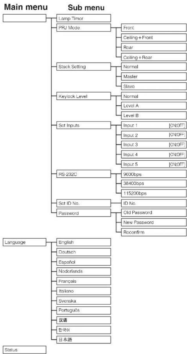
flowchart
graph TD
    A["Main menu"] --> B["Lamp Timor"]
    A --> C["PRJ Mode"]
    C --> D["Front"]
    C --> E["Ceiling + Front"]
    C --> F["Rear"]
    C --> G["Ceiling + Rear"]
    A --> H["Stack Setting"]
    H --> I["Normal"]
    H --> J["Master"]
    H --> K["Slavo"]
    A --> L["Keylock Level"]
    L --> M["Normal"]
    L --> N["Level A"]
    L --> O["Level B"]
    A --> P["Set Inputs"]
    P --> Q["Input 1 [ON/OFF"]]
    P --> R["Input 2 [ON/OFF"]]
    P --> S["Input 3 [ON/OFF"]]
    P --> T["Input 4 [ON/OFF"]]
    P --> U["Input 5 [ON/OFF"]]
    A --> V["RS-232C"]
    V --> W["9600bps"]
    V --> X["38400bps"]
    V --> Y["115200bps"]
    A --> Z["Set ID No."]
    Z --> AA["ID No."]
    Z --> AB["Password"]
    AB --> AC["Old Password"]
    AB --> AD["New Password"]
    AB --> AE["Reconfirm"]

    AF["Language"] --> AG["English"]
    AF --> AH["Deutsch"]
    AF --> AI["Espanol"]
    AF --> AJ["Nodorlands"]
    AF --> AK["Français"]
    AF --> AL["Italano"]
    AF --> AM["Svenska"]
    AF --> AN["Português"]
    AF --> AO["汉语"]
    AF --> AP["한국어"]
    AF --> AQ["日本語"]

    AR["Status"] --> AS
NOTE
- Only the items highlighted in the tree charts above can be adjusted.
- To adjust the items under the sub menu, press ▶ after selecting the sub menu.

text_image
Picture Fine Sync Audio Options Options Language StatusYou can adjust the projector's picture to your preferences with the following picture settings. See page 38 for the procedure details.
e. g. RGB input in INPUT 1 or 2 mode
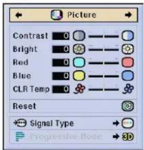
text_image
Picture Contrast 0 Bright 0 Red 0 Blue 0 CLR Temp 0 Reset Signal Type Progressive Mode 3D| Selected item | ◀ button | ▶ button |
| Contrast | For less contrast | For more contrast |
| Bright | For less brightness | For more brightness |
| Color | For less color intensity | For more color intensity |
| Tint | Skin tones become purplish | Skin tones become greenish |
| Sharp | For less sharpness | For more sharpness |
| Red | For weaker red | For stronger red |
| Blue | For weaker blue | For stronger blue |
| Reset | All image adjustment items are returned to the factory preset settings. | |
NOTE
• "Color", "Tint" and "Sharp" do not appear for RGB input in INPUT 1 or 2 mode.
- To reset all adjustment items, select "Reset" on the "Picture" menu screen and press ENTER.
- The adjustments can be stored separately in the INPUT 1 to 5 modes.
- Depending on the type of signal received, "Sharp" may not be adjustable for COMPONENT input in INPUT 1 or 2 mode.
Adjusting the Color Temperature
This function can be used to adjust the color temperature to suit the type of image input to the projector (video, computer image, TV broadcast, etc.). Decrease the color temperature to create warmer, reddish images for natural flesh tones, or increase to create cooler, bluish images for a brighter picture.
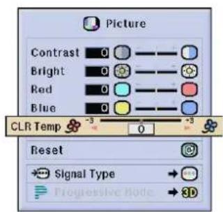
text_image
Picture Contrast 0 Bright 0 Red 0 Blue 0 CLR Temp -3 0 +3 Reset Signal Type → Progressive Node → 3D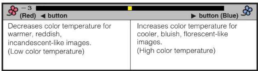
text_image
-3 (Red) ▶ button ▶ button (Blue) Decreases color temperature for warmer, reddish, incandescent-like images. (Low color temperature) Increases color temperature for cooler, bluish, florescent-like images. (High color temperature)Selecting the Signal Type (RGB menu only)
This function allows you to select the input signal type RGB or COMPONENT for INPUT 1 or 2 port.
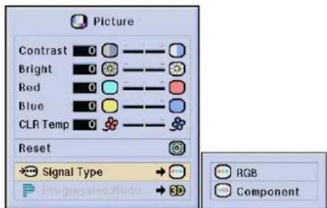
text_image
Picture Contrast 0 Bright 0 Red 0 Blue 0 CLR Temp 0 Reset Signal Type RGB Component

Progressive Mode
This function allows you to select the progressive display of a video signal. The progressive display projects a smoother video image. See page 38 for the procedure details.
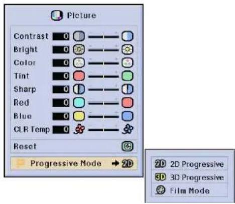
text_image
Picture Contrast 0 Bright 0 Color 0 Tint 0 Sharp 0 Red 0 Blue 0 CLR Temp 0 Reset Progressive Mode → 2D 2D 2D Progressive 3D 3D Progressive Film ModeSelects the progressive conversion mode.
2D Progressive
This function is useful to display fast-moving images such as sports and action films. This mode optimizes the image in a displayed frame.
3D Progressive
This function is useful to display relatively slow-moving images such as drama and documentary more clearly. This mode optimizes the image by estimating the movement of a number of preceding and succeeding frames.
Film Mode
Reproduces the image of film source clearly. Displays the optimized image of film transformed with three-two pull down (NTSC and PAL 60Hz) or two-two pull down (PAL 50Hz and SECAM) enhancement to progressive mode images.
* The film source is a digital video recording with the original encoded as is at 24 frames/second. The projector can convert this film source to progressive video at 60 frames/second with NTSC and PAL60Hz or at 50 frames/second with PAL50Hz and SECAM to play back a high-definition image.

NOTE
- When using progressive inputs, these inputs are directly displayed therefore 2D Progressive, 3D Progressive and Film Mode cannot be selected. These modes can be selected in interlace signals other than 1080I.
- In NTSC or PAL60Hz, even if the 3D Progressive mode has been set, the three-two pull down enhancement will be enabled automatically, when the film source has been entered.
- In PAL50Hz or SECAM, the two-two pull down enhancement will be enabled only in the Film Mode, when the film source has been entered.

Picture

Fine Sync

Audio

Options

Options

Language
Status
When displaying computer patterns which are very detailed (tiling, vertical stripes, etc.), interference may occur between the LCD pixels, causing flickering, vertical stripes, or contrast irregularities in portions of the screen. Should this occur, adjust "Clock", "Phase", "H-Pos" and "V-Pos" for the optimum computer image. See page 38 for the procedure details.
Select the desired computer input mode with INPUT 1 or 2.
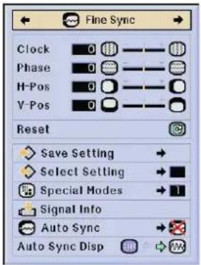
text_image
Fine Sync Clock 0 Phase 0 H-Pos 0 V-Pos 0 Reset Save Setting → Select Setting → Special Modes → 1 Signal Info Auto Sync → Auto Sync Disp →Clock
Adjusts vertical noise.
Phase
Adjusts horizontal noise (similar to tracking on your VCR).
H-Pos
Centers the on-screen image by moving it to the left or right.
V-Pos
Centers the on-screen image by moving it up or down.
NOTE
• Computer image adjustments can be made easily by pressing AUTO SYNC (☐). See page 45 for details.
- To reset all adjustment items, select "Reset" on the "Fine Sync" menu screen and press ENTER.
Saving and Selecting Adjustment Settings
This projector allows you to store up to seven adjustment settings for use with various computers. Once these settings are stored, they can be easily selected each time you connect a computer to the projector.
Saving the adjustment setting
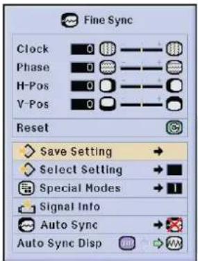
text_image
Fine Sync Clock 0 Phase 0 H-Pos 0 V-Pos 0 Reset Save Setting → Select Setting → Special Modes → 1 Signal Info Auto Sync → Auto Sync Disp →| Resolution | Vert Freq | |
| 1 | 640 × 400 | 60 Hz |
| 2 | 800 × 600 | 60 Hz |
| 3 | ||
| 4 | ||
| 5 | ||
| 6 | ||
| 7 | ||
Selecting a saved setting
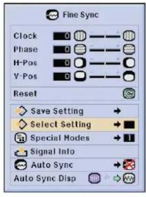
text_image
Fine Sync Clock 0 Phase 0 H-Pos 0 V-Pos 0 Reset Save Setting → Select Setting → Special Modes → Signal Info Auto Sync → Auto Sync Disp| Resolution | Vert Freq | |
| 1 | 640 x 480 | 60 Hz |
| 2 | 800 x 600 | 60 Hz |
NOTE
- If a memory position has not been set, a resolution and frequency setting will not be displayed.
- When selecting the stored adjustment setting with "Select Setting", the computer system should match the stored setting.

Picture

Fine Sync

Audio

Options

Options

Language
Status
Special Mode Adjustment
Ordinarily, the type of input signal is detected and the correct resolution mode is automatically selected. However, for some signals, the optimal resolution mode in "Special Modes" on the "Fine Sync" menu screen may need to be selected to match the computer display mode. See page 38 for the procedure details.
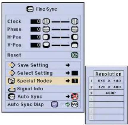
text_image
Fine Sync Clock 0 Phase 0 H-Pos 0 V-Pos 0 Reset Save Setting → Select Setting → Special Modes → Signal Info Auto Sync → Auto Sync Disp → Resolution 1 640 × 480 2 720 × 480 3 400PNOTE
- Avoid displaying computer patterns which repeat every other line (horizontal stripes). (Flickering may occur, making the image hard to see.)
- When inputting DTV 480P or 1080I signals, select the corresponding type of signal.
Checking the Input Signal
This function allows you to check the current input signal information.
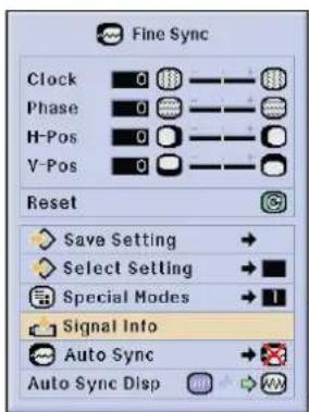
text_image
Fine Sync Clock 0 Phase 0 H-Pos 0 V-Pos 0 Reset Save Setting → Select Setting → Special Modes → 1 Signal Info Auto Sync → Auto Sync Disp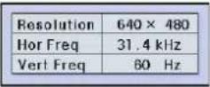

Picture

Fine Sync

Audio

Options

Options

Language
Status
Auto Sync Adjustment
• Used to automatically adjust a computer image.
- Auto Sync adjustment can be made manually by pressing AUTO SYNC, or automatically by setting "Auto Sync" to "Normal" or "High Speed" in the projector's GUI menu. See page 38 for the procedure details.
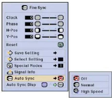
text_image
Fine Sync Clock 0 Phase 0 H-Pos 0 V-Pos 0 Reset Save Setting → Select Setting → Special Modes → 1 Signal Info Auto Sync → Auto Sync DispOff
- Synchronized adjustment is not automatically performed.
- Press AUTO SYNC to perform manual adjustment.
Normal
- Synchronized adjustment is automatically performed the same as the "High Speed" setting.
- Adjustment using the "Normal" setting takes longer to perform than using the "High Speed" setting, but it is more accurate.
High Speed
- The sync adjustment is automatically made each time the projector is turned on while connected to a computer or the input selection is changed.
- The Auto Sync adjustment setting previously made is cleared when the projector's setting is changed.
NOTE
• Automatic adjustments can be made by pressing AUTO SYNC.
- When performing AUTO SYNC in Off or High Speed mode, if you press AUTO SYNC once, then press it again within one minute, AUTO SYNC will be executed in Normal mode.
• Auto Sync adjustment may take some time to complete, depending on the image of the computer connected to the projector.
- When the optimum image cannot be achieved with Auto Sync adjustment, use manual adjustments. (See page 43.)
Auto Sync Display Function
Normally, an image is not superimposed during Auto Sync adjustment. You can, however, choose to superimpose a background image during Auto Sync adjustment.
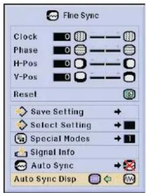
text_image
Fine Sync Clock 0 Phase 0 H-Pos 0 Y-Pos 0 Reset Save Setting Select Setting Special Modes Signal Info Auto Sync Auto Sync Disp
Picture

Fine Sync

Audio

Options

Options

Language
Status
This projector's audio is factory preset to standard settings. However, you can adjust it to suit your own preferences by adjusting the following audio settings. See page 38 for the procedure details.

text_image
Audio Balance 0 Treble 0 Bass 0 Reset Audio Out Speaker| ◀ buttonSelected item | ▶ button | |
| Balance | Increased audio from the left speaker | Increased audio from the right speaker |
| Treble | For weaker treble | For stronger treble |
| Bass | For weaker bass | For stronger bass |
| Reset | All audio adjustment items are returned to the factory preset settings. | |
NOTE
- To reset all adjustment items, select "Reset" on the "Audio" menu screen and press ENTER.
Audio Out
FAO (Fixed audio output): Audio output that does not vary in strength with the volume level of the source projector.
VAO (Variable audio output): Audio output that varies in strength with the volume level of the source projector.
Speaker
Switching the built-in speakers on the projector ON/OFF.


Picture in Picture function allows you to display two pictures on the same screen. You can display the image input from INPUT 4 or 5 as an inset picture overlapping the main picture input from INPUT 1, 2 or 3. See page 38 for the procedure details.
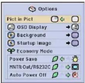
text_image
Options Pict in Pict OSD Display Background Startup Image Economy Mode Power Save MNTR Out/RS232C Auto Power Off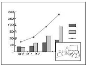
bar_line
| Year | Category A | Category B | |---|---|---| | 1996 | 40 | 35 | | 1997 | 50 | 70 | | 1998 | 75 | 120 | | 2000 | 90 | 180 | | 2001 | 100 | 280 |1 Press ◀ to select "☐" to display an inset picture (Factory preset to INPUT 4).
2 Press ◀/▶/▲/▼ to move the inset picture to one of four preset positions.
NOTE
• The image from INPUT 1, 2 or 3 is displayed as the main picture and the image from INPUT 4 or 5 is displayed as the inset picture.
- The last displayed image from INPUT 4 or 5 is displayed as the inset picture. For example, when you want to display the image from INPUT 4 as the inset picture, select INPUT 4, then select the main picture, and then select "Pict in Pict".
- Inset picture can only be displayed in video signal of NTSC/PAL/SECAM.
- When selecting the image for the inset picture, only the images being input will be displayed.
- The audio of the inset picture will come out of the projector's speakers.
- Picture in Picture does not work in case of the following RGB signals. UXGA signal image/SXGA+ signal image/Interlaced signal/DTV (480P/580P/720P/1035I/1080I)
- You can only use the following functions while in Picture in Picture mode. FREEZE: Works for the inset picture only.

Reducing Image Noise [DNR] (VIDEO menu only)
![SHARP XG-P25X - Reducing Image Noise [DNR] (VIDEO menu only) - 1](/content/2026/05/817466/images/c3aed425b8f5150cba6423caa065fb6a8cbd82838c7365c12575d7313fc31566.jpg)
![SHARP XG-P25X - Reducing Image Noise [DNR] (VIDEO menu only) - 2](/content/2026/05/817466/images/a174e378241efe929627c5f70c2af2c6226e7b7df4ebbde3bcf569ae4b84caf3.jpg)
![SHARP XG-P25X - Reducing Image Noise [DNR] (VIDEO menu only) - 3](/content/2026/05/817466/images/5ec562b7c638ca6e1d8d82cfeb5b0adf60aa98b598225242bdac47ffae66d90d.jpg)
![SHARP XG-P25X - Reducing Image Noise [DNR] (VIDEO menu only) - 4](/content/2026/05/817466/images/e9d0f604f0c54c7793a167cd8d59335f8761ff4d116ec6a7dfd475a5b62e345a.jpg)
![SHARP XG-P25X - Reducing Image Noise [DNR] (VIDEO menu only) - 5](/content/2026/05/817466/images/ee21537c7f6d415cc54bb6f1cb25327e6a8eb5af0e4973ad0c9ccfdd7e8f2fc9.jpg)
![SHARP XG-P25X - Reducing Image Noise [DNR] (VIDEO menu only) - 6](/content/2026/05/817466/images/639f026299739854ebd335b75a5a7bab4772a2d60ecf89b64786eb7c8c8164ec.jpg)
Digital Noise Reduction (DNR) provides high quality images with minimal dot crawl and cross color noise. See page 38 for the procedure details.
![SHARP XG-P25X - Reducing Image Noise [DNR] (VIDEO menu only) - 7](/content/2026/05/817466/images/3c46b1fdc97205ca2f6e4d4d9ad7ca4e7d534e51e7977e4928b6e21fe7524084.jpg)
text_image
Options DNR OSD Display Video System Background Startup Image Economy Mode Power Save MNTR Out/RS232C Auto Power OffNOTE
- If the image is clear, select "☐" to prevent any blurring.

This function allows you to turn on or off the on-screen messages that appear during input select. See page 38 for the procedure details.
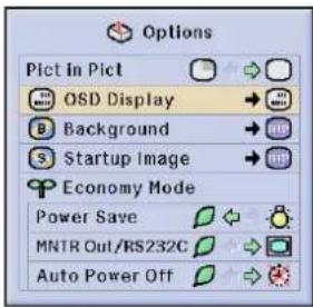
text_image
Options Pict in Pict OSD Display Background Startup Image Economy Mode Power Save MNTR Out/RS232C Auto Power Off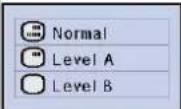
| Selected item | Description |
| Normal | All On-screen Display are displayed. |
| Level A | Input/Custom/Freeze/Enlarge/Auto sync/Volume/Mute/Black screen functions are not displayed. |
| Level B | All On-screen Display are not displayed (except Menu/Lens functions and warning display (Power off/Temp./Lamp function etc.)). |

Setting the Video Signal (VIDEO menu only)


The video input system mode is preset to "Auto"; however, it can be changed to a specific system mode if the selected system mode is not compatible with the connected audiovisual equipment. See page 38 for the procedure details.
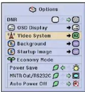
text_image
Options DNR OSD Display Video System Background Startup Image Economy Mode Power Save MNTR Out/RS232C Auto Power Off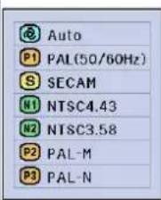
text_image
Auto P1 PAL(50/60Hz) SECAM N1 NTSC4.43 N2 NTSC3.58 P2 PAL-M P3 PAL-NNOTE
- When the system mode is set to "Auto", you may not receive a clear picture due to signal differences. Should this occur, switch to the video system of the source signal.
- AUTO cannot be set for PAL-M and PAL-N input signals. Select "PAL-M" or "PAL-N" in "Video System" menu for PAL-M and PAL-N input signals.

This function allows you to select the image displayed when no signal is being sent to the projector. See page 38 for the procedure details.
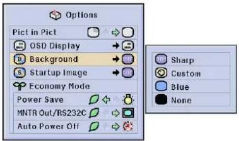
text_image
Options Pict in Pict OSD Display Background Startup Image Economy Mode Power Save MNTR Out/RS232C Auto Power Off Sharp Custom Blue None| Selected item | Description |
| Sharp | SHARP default image |
| Custom | User customized image (e.g. company logo) |
| Blue | Blue screen |
| None | Black screen |
NOTE
- By selecting "Custom", the projector can display a custom image (e.g. your company logo) as the background image. The custom image must be a 256-color BMP file with a picture size no larger than 1,024 × 768 pixels. Please see the Sharp Advanced Presentation Software operation manual on the CD-ROM for how to save (or change) a custom image.

Selecting a Startup Image


This function allows you to specify the image to be displayed upon the projector's startup. A custom image (e.g. your company logo) can be uploaded to the projector via an RS-232C cable. See page 20 in this operation manual, and also the supplied Sharp Advanced Presentation Software operation manual on the CD-ROM for detailed instructions. See page 38 for the procedure details.
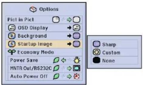
text_image
Options Pict in Pict OSD Display Background Startup Image Economy Mode Power Save MNTR Out/RS232C Auto Power Off Sharp Custom None| Selected item | Description |
| Sharp | SHARP default image |
| Custom | User customized image (e.g. company logo) |
| None | Black screen |
NOTE
- By selecting "Custom", the projector can display a custom image (e.g. your company logo) as the startup image. The custom image must be a 256-color BMP file with a picture size no larger than 1,024 × 768 pixels. Please see the Sharp Advanced Presentation Software operation manual on the CD-ROM for how to save (or change) a custom image.


These functions allow you to reduce the power consumption. See page 38 for the procedure details.
Power Save Function
Function to control the quantity of projected light. Select “(Low Power Mode)” or “(Standard Mode)” to decrease or increase brightness, fan noise and power consumption.
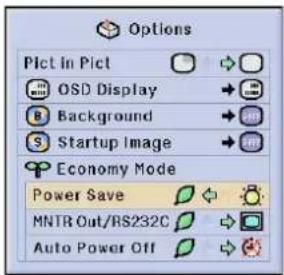
text_image
Options Pict in Pict OSD Display Background Startup Image Economy Mode Power Save MNTR Out/RS232C Auto Power Off| Quantity of light is 85%.Power consumption is about 350 W. | |
| Quantity of light is 100%.Power consumption is 380 W. |
NOTE
- "Power Save" mode is factory preset to ".(Standard Mode)".
- Even when selecting "☐ (Low Power Mode)" in "Power Save" mode, fan noise may increase if internal temperature rises enough to activate the cooling function.
Monitor Out/RS-232C Off Function
This projector consumes power when using a monitor connected to the OUTPUT port for INPUT 1, 2 and a computer connected to the RS-232C port. When not using these ports, "MNTR Out/RS232C" can be set to "☐" to reduce standby power consumption.
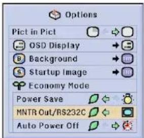
text_image
Options Pict in Pict OSD Display Background Startup Image Economy Mode Power Save MNTR Out/RS232C Auto Power Off| Standby power for Monitor Out/RS-232C connection turned off. | |
| Monitor Out/RS-232C on |
CAUTION
- Set "MNTR Out/RS232C" to "☐" when using the Sharp Advanced Presentation Software (supplied).
Automatic Power Shutoff Function
When no input signal is detected for more than 15 minutes, the projector will automatically shut off. The on-screen message, "Power OFF in 5 min." will appear five minutes before the power is automatically turned off.
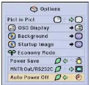
text_image
Options Pict in Pict OSD Display Background Startup Image Economy Mode Power Save MNTR Out/RS232C Auto Power Off| Power automatically shuts off after about 15 minutes of no signal input. | |
| Automatic Power Shutoff disabled. |
NOTE
- "MNTR Out/RS232C" is factory preset to "☐", and "Auto Power Off" is factory preset to "☐".

Picture

Fine Sync

Audio

Options

Options

Language
Status
This function allows you to check the accumulated lamp usage time. See page 38 for the procedure details.
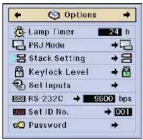
text_image
Options Lamp Timer 24 h PRJ Mode Stack Setting Keylock Level Set Inputs RS-232C 9600 bps Set ID No. 001 PasswordNOTE
- It is recommended that the lamp be replaced after approximately 1,400 cumulative hours of use. See pages 64 and 65 for lamp replacement.

Reversing/Inverting Projected Images

Picture

Fine Sync

Audio

Options

Options

Language
Status
This projector is equipped with a reverse/invert image function which allows you to reverse or invert the projected image for various applications. See page 38 for the procedure details.
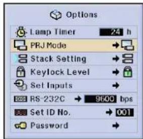
text_image
Options Lamp Timer 24 h PRJ Mode Stack Setting Keylock Level Set Inputs RS-232C → 9600 bps Set ID No. → 001 Password →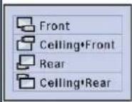
| Selected item | Description |
| Front | Normal image |
| Ceiling + Front | Inverted image |
| Rear | Reversed image |
| Ceiling + Rear | Reversed and inverted image |
NOTE
- This function is used for the reversed image and ceiling-mount setups. See page 30 for these setups.

Picture

Fine Sync

Audio

Options

Options

Language
Status
You can double the brightness of an image by stacking two projectors and projecting the same picture simultaneously. (Stack Projection)
Connect two projectors by using the RS-232C cable. Then assign one as the master and the other as the slave. In this way, you can control two projectors with one remote control. See page 38 for the procedure details.
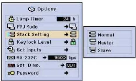
text_image
Options Lamp Timer 24 h PRJ Mode → Stack Setting → Keylock Level → Set Inputs → RS-232C → 9600 bps Set ID No. → 001 Password → Normal Master SlaveNOTE
- When operating the master projector with the remote control, actuating signals are transmitted to the slave projector through RS-232C, which then responds in concert with the master. The buttons below can control both the master and the slave at one time.
POWER ON, POWER OFF, BLACK SCREEN, INPUT (1, 2, 3, 4 or 5)
- The slave projector cannot be controlled directly with the remote control.
• Even after setting up for stack projection, you can still control each projector by one of the methods below.
(a) Use the operation buttons on the projector.
(b) Connect the remote control to the projector with a cable.
- For details on intended purpose, see pages 59 to 62.

Locking the Operation Buttons on the Projector

Picture

Fine Sync

Audio

Options

Options

Language
Status
This function can be used to lock the use of certain operation buttons on the projector. The user can still operate the projector fully with the remote control. See page 38 for the procedure details.
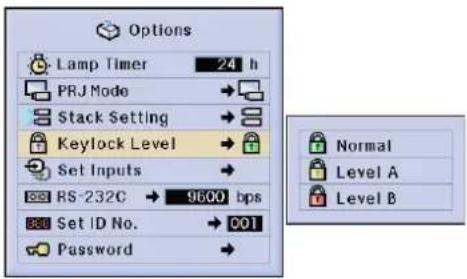
text_image
Options Lamp Timer 24 h PRJ Mode → Stack Setting → Keylock Level → Set Inputs → RS-232C → 9600 bps Set ID No. → 001 Password → Normal Level A Level B| Selected item | Description |
| Normal | All operation buttons are functional. |
| Level A | Only Input/Volume/Mute functions on the projector are available. |
| Level B | All operation buttons on the projector are unavailable. |
NOTE
- To cancel the Keylock Level, perform the above procedure using the remote control.
• See page 55 for details using the password function.

Picture

Fine Sync

Audio

Options

Options

Language
Status
This function allows you to deselect unwanted signal input. See page 38 for the procedure details.
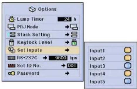
text_image
Options Lamp Timer 24 h PRJ Mode → Stack Setting → Keylock Level → Set Inputs → RS-232C → 9600 bps Set ID No. → 001 Password → Input1 Input2 Input3 Input4 Input5NOTE
- When stack projecting, multi-screen projecting and so on, this function can be used to cancel the RS-232C control.
- Up to two input signals can be blocked for both Input 1, 2, 3 or Input 4, 5.
- For details on intended purpose, see pages 59 to 62.

Selecting the Transmission Speed (RS-232C)

Picture

Fine Sync

Audio

Options

Options

Language
Status
This menu allows you to adjust the transmission speed of the RS-232C connection by selecting the baud rate. See page 38 for the procedure details.
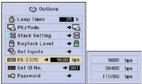
text_image
Options Lamp Timer 25 h PRJ Mode → Stack Setting → Keylock Level → Set Inputs → RS-232C → 9600 bps Set ID No. → 001 Password → 9600 bps 38400 bps 115200 bpsNOTE
- Make sure that both the projector and computer are set for the same baud rate. Refer to the computer's operation manual for instructions for setting the baud rate.

This projector can form a network of up to 250 projectors. To identify separately and control specified projector, you need to set ID No.. The ID No. is factory preset to "001". See page 38 for the procedure details.
Setting the ID No.
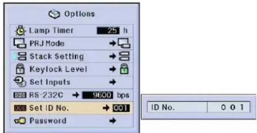
text_image
Options Lamp Timer 25 h PRJ Mode → Stack Setting → Keylock Level → Set Inputs → RS-232C → 9600 bps Set ID No. → C01 Password → ID No. 0 0 1Press ▶ to select the first digit and ▲/▼ to select the desired number. Continue this procedure for the remaining two digits.
NOTE
- Be sure to set the ID No. in the Option menu and attach a corresponding number seal to the projector.
• The ID No. can be set from 001 to 250.
• For details on intended purpose, see pages 57 to 62

A password can be set by the user and used with the keylock level to prevent adjustments to certain settings on the GUI. See page 38 for the procedure details.
NOTE
- When password is set, you need to enter the password to use "PRJ Mode", "Stack Setting", "Keylock Level", "Set Inputs", "RS-232C" and "Set ID No." menus.
Setting the Password
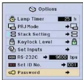
text_image
Options Lamp Timer 25 h PRJ Mode Stack Setting Keylock Level Set Inputs RS-232C 9600 bps Set ID No. 001 Password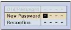
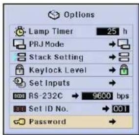
text_image
Options Lamp Timer 25 h PRJ Mode Stack Setting Keylock Level Set Inputs RS-232C 9600 bps Set ID No. 001 Password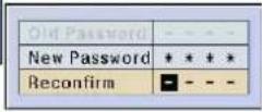
1 Enter the new password using ▲/▼ to select the desired number, and then press ▶ to select the next digit. Continue this procedure for the remaining three digits, and then press ENTER.
2 Enter the password again ("Reconfirm") using ▲/▼/◄/►, and then press ENTER.
NOTE
• After setting the password, be sure to write it down in a secure location in case you can not remember it.
Changing the Password
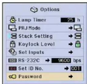
text_image
Options Lamp Timer 25 h PRJ Mode → Stack Setting → Keylock Level → Set Inputs → RS-232C → 9600 bps Set ID No. → 001 Password →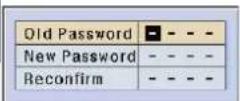
1 Enter the old password using ▲/▼/◄/►, and then press ENTER.
2 Enter the new password using ▲/▼/◄/►, and then press ENTER.
3 Enter the password again ("Reconfirm") using ▲/▼/◄/►, and then press ENTER.

Picture

Fine Sync

Audio

Options

Options

Language
Status
English is the preset language for the On-screen Display; however, this can be changed to German, Spanish, Dutch, French, Italian, Swedish, Portuguese, Chinese, Korean or Japanese. See page 38 for the procedure details.

text_image
Language English Deutsch Español Nederlands Français Italiano Svenska Português 汉语 한국어 日本語
Displaying the Adjustment Settings

Picture

Fine Sync

Audio

Options

Options

Language

This function can be used to display all the adjusted settings on the screen simultaneously. See page 38 for the procedure details.
INPUT 1, 2 (RGB) or 3 (DIGITAL) mode INPUT 4, 5 (VIDEO) mode
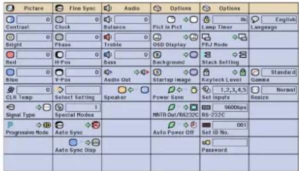
text_image
Picture 0 Contrast 0 Bright 0 Red 0 Blue 0 CLR Temp Select Setting 1 Special Nodes Auto Sync Disp Audio Balance Trobble Bass Audio Out Speaker Options Pict in Pict OISD Display Background Startup Image Power Save MNTR Out/RS232C Auto Power Off Options Lamp Timer PHJ Mode Stack Setting Keylock Level Set Inputs 9600bps Rs-232C 001 Set ID No. Password Normal Resize Progressive Mode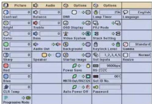
text_image
Picture Audio Options Options Contrast Balance DNR Loop Timer Language Bright Treble O&D Display PBJ Mode Color Bass Video System Stack Setting Int Audio Out Background Keylock Level Standard Sharp Speaker Startup Image 1,2,3,4,5 Set inputs Normal Resize Red 0 Power Save 9600bps RS-232C Blue MNTR Out/RS232C 001 CLR Temp Auto Power Off Password Progressive ModeThis projector has outstanding network capability.
- Internet access for self-diagnosis
- Multiple and group projector control
- Simultaneous multiple projector control
Internet access for self-diagnosis, status information and preventive maintenance
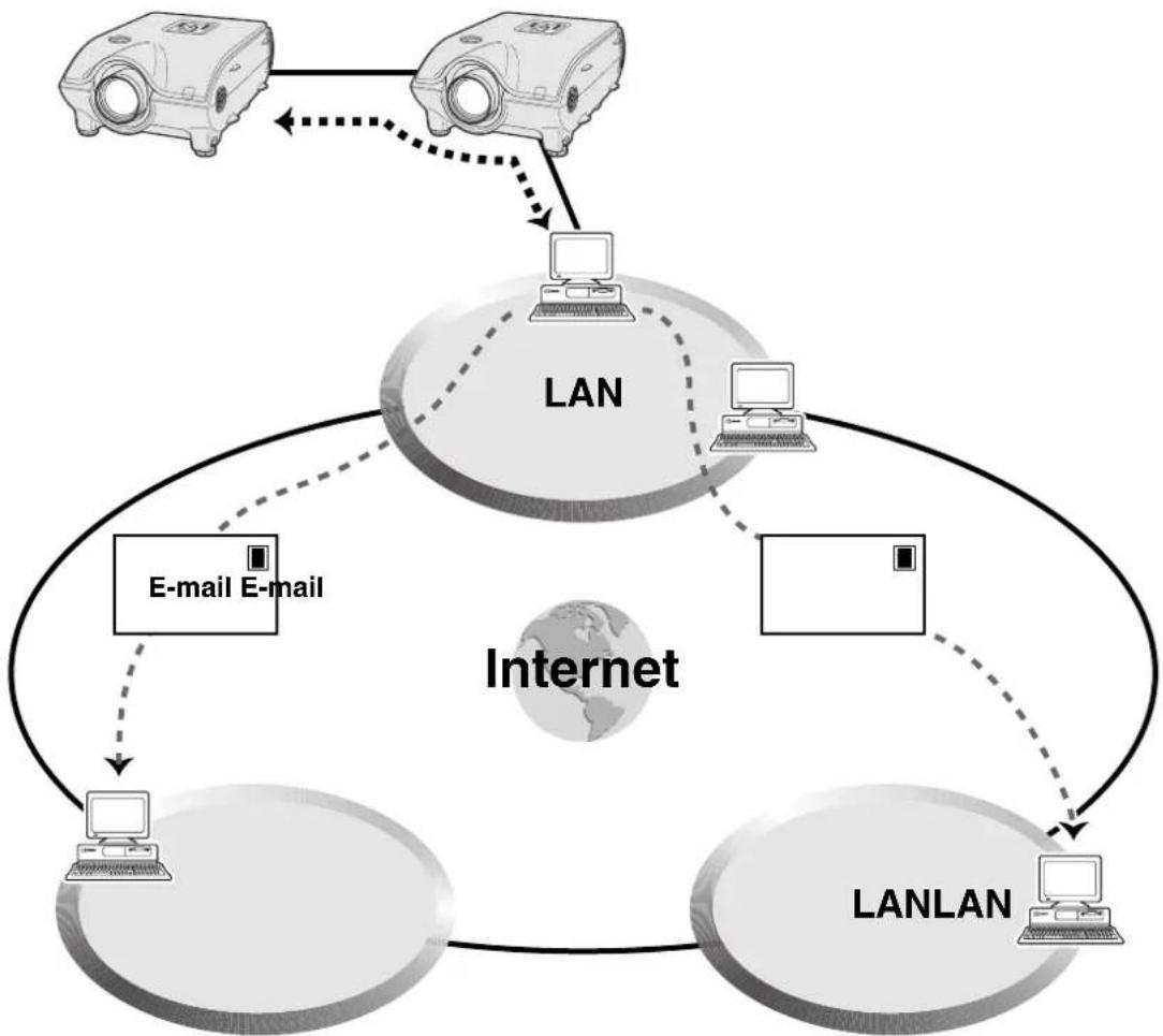
This projector can be used in a network of up to 250 projectors managed from a single PC with the accompanied Sharp Advanced Presentation Software Professional Edition. This projector can be connected to a PC using an RS-232C connection. Output terminals are provided (RS-232C on the projector) enabling a daisy chain configuration and eliminating the need for a distributor.
This projector is also equipped with a function to send status information (lamp usage time, etc.) to a Sharp Service Center or outside contractor for quick and efficient customer service.
NOTE
- For more information on these features, see the operation manuals accompanying the Sharp Advanced Presentation Software Professional Edition.
Multiple and group projector control via computer
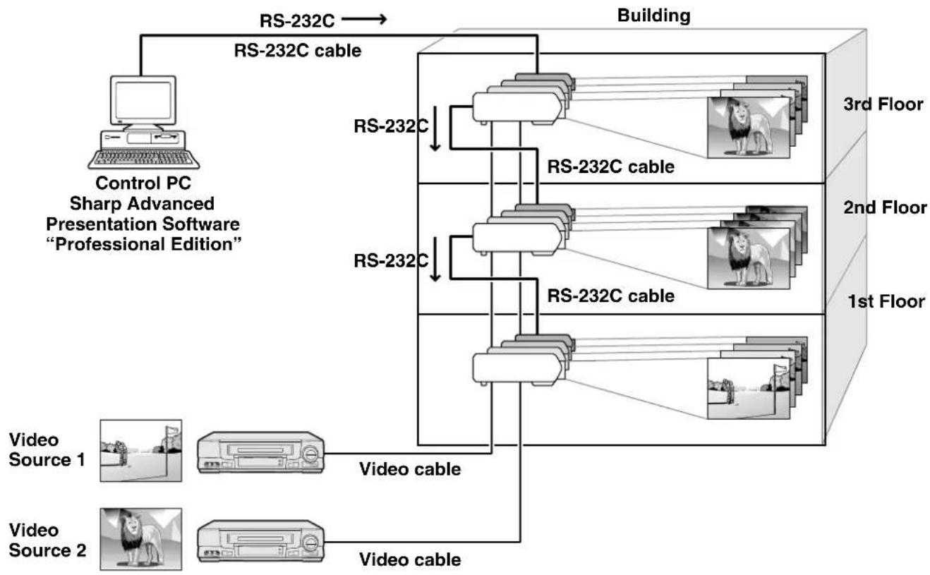
flowchart
graph TD
    A["Control PC\nSharp Advanced Presentation Software\n"Professional Edition""] -->|RS-232C| B["Building"]
    B --> C["1st Floor"]
    B --> D["2nd Floor"]
    B --> E["3rd Floor"]
    C --> F["Video Source 1"]
    C --> G["Video Source 2"]
    C --> H["Video cable"]
    D --> I["RS-232C cable"]
    D --> J["RS-232C cable"]
    E --> K["RS-232C cable"]
    E --> L["RS-232C cable"]
    F --> M["Video cable"]
    G --> N["Video cable"]
    H --> O["Video cable"]
This projector can be used in a network of projectors managed from a single PC with the accompanied Sharp Advanced Presentation Software Professional Edition. Projectors in conference rooms on the first and third floors of a building, for example, can be used for video presentations, while projectors on the second floor can be used for PC-assisted presentations. Projectors can even be powered down at different times (e.g., projectors on the first and second floors are powered down in one hour, while those on the third floor are powered down in two hours).
NOTE
- For more information on these features, see the operation manuals accompanying the Sharp Advanced Presentation Software Professional Edition.
- Transmission performance of the RS-232C cable can vary depending on the surrounding conditions. Use the transmission repeater if performance is not up to par.
• We recommend you use an RS-232C cable not longer than 49' 3" (15 m).
Stack Projection
For brighter images, two projectors can be stacked using the Stack Setting function.
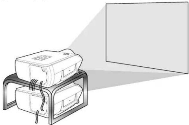
natural_image
Illustration of a device mounted on a stand with cables, next to a blank screen (no text or symbols)Basic
Computer
Projector 1
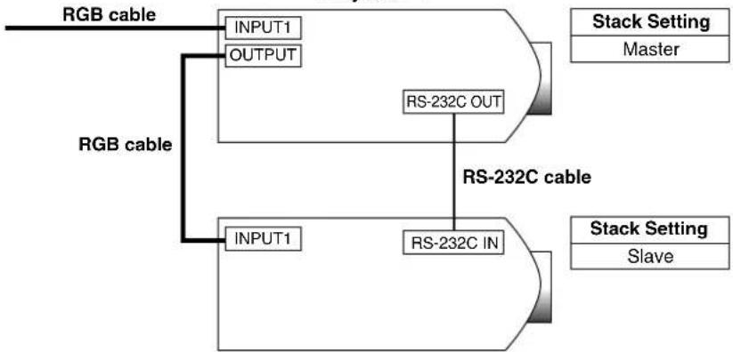
flowchart
graph TD
    A["RGB cable"] --> B["INPUT1"]
    A --> C["OUTPUT"]
    B --> D["RS-232C OUT"]
    C --> E["RS-232C IN"]
    F["RGB cable"] --> G["INPUT1"]
    F --> H["OUTPUT"]
    D --> I["Stack Setting: Master"]
    E --> J["Stack Setting: Slave"]
Projector 2
Below are the steps for making a stack projection as shown in the diagram above.
1 Set the "Stack Setting" of Projector 1 to "Master". (See page 52 for details.)
2 Set the "Stack Setting" of Projector 2 to "Slave". (See page 52 for details.)
3 Select the same RS-232C transmission speed for both Projector 1 and Projector 2. (See page 53 for details.)
4 Adjust the "Set Inputs" setting as the table below. (See page 53 for details.)
Projector 1 (Master)
| Set Inputs | |
| INPUT1 | ON |
| INPUT2 | OFF |
| INPUT3 | OFF |
| INPUT4 | OFF |
| INPUT5 | OFF |
Projector 2 (Slave)
| Set Inputs | |
| INPUT1 | ON |
| INPUT2 | OFF |
| INPUT3 | OFF |
| INPUT4 | OFF |
| INPUT5 | OFF |
NOTE
Set input terminals you will use to "ON". Set input terminals you will not use to "OFF".
5 Turn off the projector.
6 Connect the INPUT 1 port on Projector 1 to the RGB port on the computer using an RGB cable. (See page 16 for details.)
7 Connect the OUTPUT port on Projector 1 to the INPUT 1 port on Projector 2 using an RGB cable. (See page 21 for details.)
NOTE
When connecting an RGB cable to Projector 2, use the input port that has the same number as Projector 1. (INPUT 1, in this case)
8 Connect the RS-232C OUT port on Projector 1 to the RS-232C IN port on Projector 2 using an RS-232C cable.
(See page 20 for details.)
9 Turn on the projector first, then turn on the computer.
Application
When inputting multiple image sources, refer to the example below to adjust Set Inputs.

flowchart
graph TD
    A["Computer 1"] -->|RGB cable| B["Projector 1"]
    C["Computer 2"] -->|RGB cable| B
    D["DVD video player"] -->|Distributor| E["Projector 2"]
    E -->|RS-232C IN| B
    E -->|RS-232C OUT| B
    B -->|INPUT1| F["Stack Setting Master"]
    B -->|INPUT2| G["Stack Setting Master"]
    B -->|OUTPUT| H["Stack Setting Master"]
    B -->|INPUT4| I["Stack Setting Master"]
    E -->|INPUT1| J["Stack Setting Slave"]
    E -->|INPUT4| K["Stack Setting Slave"]
Projector 1 (Master)
| Set Inputs | |
| INPUT1 | ON |
| INPUT2 | ON |
| INPUT3 | OFF |
| INPUT4 | ON |
| INPUT5 | OFF |
Projector 2 (Slave)
| Set Inputs | |
| INPUT1 | ON |
| INPUT2 | OFF |
| INPUT3 | OFF |
| INPUT4 | ON |
| INPUT5 | OFF |
Videowall
In the past, to setup a video wall, it was necessary to purchase a costly image-processing device, designed exclusively for the purpose.
The XG-P25X has built-in video wall capability that doesn't require additional expensive equipment.
Basic
Following is an example of how to build a 2X2 video wall using 4 projectors as shown above.
NOTE
Install the supplied Sharp Advanced Presentation Software Professional Edition in advance. For installation details, refer to the guide for this software.
1 Select the same RS-232C transmission speed for all projectors. (See page 53 for details on selecting transmission speed.)
2 Set the ID No. for each projector. (See page 54 for details on setting the ID No.)
3 Turn off all the projectors.
4 Connect the computer with Sharp Advanced Presentation Software Professional Edition to the 4 projectors using a RS-232C cable as the Connection Diagram 1 below. (See page 20 for details on connecting RS-232C cable.)
5 Turn on the computer, then launch Sharp Advanced Presentation Software Professional Edition.
6 Select "Use ID Number" at the Operation Mode Setting. (See the Sharp Advanced Presentation Software Professional Edition installation guide for setup details.)
7 Execute Scan at Scan Setting. (See the Sharp Advanced Presentation Software Professional Edition installation guide for details.)
8 Click Power ON at the Multiple Control window. If the projectors are connected and setup correctly, all the projectors will turn on. If power does not turn on, check connections and try again.
9 Group the projectors at Group Setting. (See the Sharp Advanced Presentation Software Professional Edition installation guide for details.)
10 Perform video wall setup at Video Wall Setting. (See the Sharp Advanced Presentation Software Professional Edition installation guide for setup details.)
That completes video wall setup. When the same image signal is input to all the projectors, video wall projection starts.
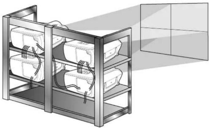
natural_image
Illustration of a multi-level storage unit with internal wiring and a transparent box (no text or symbols)NOTE
Video wall is not compatible with resolutions higher than SXGA.
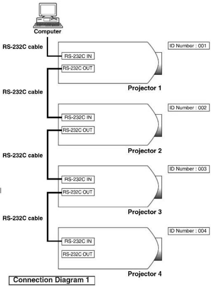
flowchart
graph TD
    A["Computer"] --> B["RS-232C cable"]
    B --> C["RS-232C IN"]
    B --> D["RS-232C OUT"]
    E["RS-232C cable"] --> F["Projector 1"]
    F --> G["ID Number: 001"]
    E --> H["Projector 2"]
    H --> I["ID Number: 002"]
    E --> J["Projector 3"]
    J --> K["ID Number: 003"]
    E --> L["Projector 4"]
    L --> M["ID Number: 004"]
    N["RS-232C cable"] --> O["RS-232C IN"]
    N --> P["RS-232C OUT"]
    Q["RS-232C cable"] --> R["RS-232C IN"]
    Q --> S["RS-232C OUT"]
    T["RS-232C cable"] --> U["RS-232C IN"]
    T --> V["RS-232C OUT"]
Application
Using Stack Setting and Set Inputs functions together allows you to control the video wall with one remote control. Connection Diagram 2 below shows how the video wall is connected based on the example in the previous section.
NOTE
Perform the procedure below after setting up the basic connection.
1 Adjust the Set Inputs setting for each projector as the table below.
(See page 53 for setup details)
Projector 1
| Set Inputs | |
| INPUT1 | ON |
| INPUT2 | ON |
| INPUT3 | OFF |
| INPUT4 | ON |
| INPUT5 | OFF |
Projector 2-4
| Set Inputs | |
| INPUT1 | ON |
| INPUT2 | OFF |
| INPUT3 | OFF |
| INPUT4 | ON |
| INPUT5 | OFF |
NOTE
- Set input terminals you will use to "ON". Set input terminals you will not use to "OFF".
2 Adjust the Stack Setting for each projector as the table below.
(See page 52 for setup details)
Projector 1
| Stack Setting |
| Master |
Projector 2-4
| Stack Setting |
| Slave |
3 Turn off the projector.
4 Make all connections as shown in Connection Diagram 2.
5 Turn on the projector first, then the computers and video player.


Computer 1 Computer 2
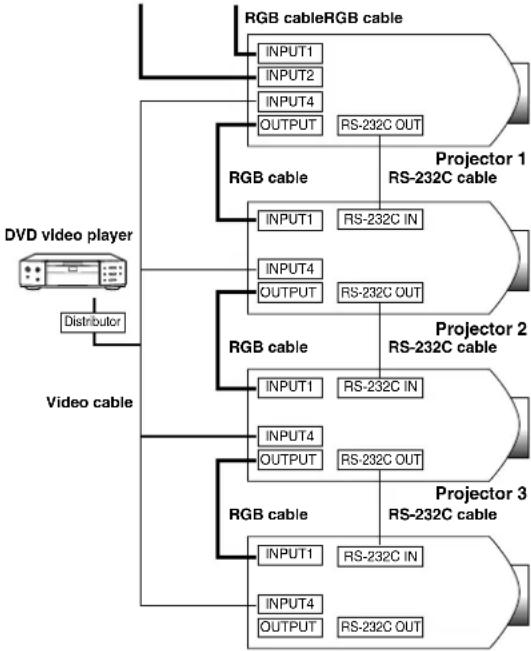
flowchart
graph TD
    A["DVD video player"] --> B["Distribution"]
    B --> C["RGB cable RGB cable"]
    C --> D["INPUT1 INPUT2 INPUT4 OUTPUT"]
    D --> E["RS-232C OUT"]
    F["Video cable"] --> G["RGB cable"]
    G --> H["INPUT1 INPUT2 INPUT4 OUTPUT"]
    H --> I["RS-232C IN"]
    I --> J["Projector 1 RS-232C cable"]
    G --> K["RGB cable"]
    K --> L["INPUT1 INPUT2 INPUT4 OUTPUT"]
    L --> M["RS-232C OUT"]
    N["Projector 2 RS-232C cable"] --> O["RGB cable"]
    O --> P["INPUT1 INPUT2 INPUT4 OUTPUT"]
    P --> Q["RS-232C IN"]
    O --> R["RGB cable"]
    R --> S["INPUT1 INPUT2 INPUT4 OUTPUT"]
    S --> T["RS-232C OUT"]
    U["Projector 3 RS-232C cable"] --> V["RGB cable"]
    V --> W["INPUT1 INPUT2 INPUT4 OUTPUT"]
    W --> X["RS-232C IN"]
    V --> Y["RGB cable"]
    Y --> Z["INPUT1 INPUT2 INPUT4 OUTPUT"]
    Z --> AA["RS-232C OUT"]
Connection Diagram 2
Projector 4
NOTE
- Image quality may deteriorate when picture signals are input through multiple projectors in a daisy chain connection.
Maintenance Indicators
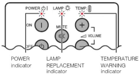
text_image
POWER ON LAMP MUTE TEMP VOLUME POWER indicator LAMP REPLACEMENT indicator TEMPERATURE WARNING indicator- The warning lights on the projector indicate problems inside the projector.
- There are two warning lights: a TEMPERATURE WARNING indicator which warns that the projector is too hot, and a LAMP REPLACEMENT indicator which lets you know when to change the lamp.
- If a problem occurs, either the TEMPERATURE WARNING indicator or the LAMP REPLACEMENT indicator will light up red. After turning off the power, follow the procedures given below.
| Maintenance Indicator | Condition Possible Solution problem | ||
| TEMPERATURE WARNING indicator | The internal temperature is abnormally high. | • Blocked air intake. | • Relocate the projector to an area with proper ventilation. |
| • Clogged air filter. | • Clean the filter.(See page 66.) | ||
| • Cooling fan breakdown.• Internal circuit failure. | • Take the projector to your nearest Sharp Authorized LCD Projector Dealer or Service Center for repair. | ||
| LAMP REPLACE-MENT indicator | The lamp does not light up. | • Burnt-out lamp.• Lamp circuit failure. | • Carefully replace the lamp. (See pages 64 and 65.)• Take the projector to your nearest Sharp Authorized LCD Projector Dealer or Service Center for repair. |
| The lamp requires replacement. | • Lamp has been used for over 1,400 hours. | ||
| POWER indicator | The POWER indicator blinks in red when the projector is on. | • The filter cover is open. | • Securely install the filter cover.• If the POWER indicator blinks even when the filter cover is securely installed, contact your nearest Sharp Authorized LCD Projector Dealer or Service Center for advice. |
NOTE
- If the TEMPERATURE WARNING indicator lights up, follow the above possible solutions and then wait until the projector has cooled down completely before turning the power back on. (At least 5 minutes.)
- If the power is turned off and then turned on again, as during a brief rest, the LAMP REPLACEMENT indicator may be triggered, preventing the power from going on. Should this occur, take the power cord out of the wall outlet and put it back in again.
Lamp
The lamp in this projector operates for approximately 1,500 cumulative hours, depending on the usage environment. It is recommended that the lamp be replaced after 1,400 cumulative hours of use or when you notice a significant deterioration of the picture and color quality. The lamp usage time can be checked with the On-screen Display. (see page 51.)

CAUTION
- Intense light hazard. Do not attempt to look into the aperture and lens while the projector is operating.
NOTE
- As the usage environment can vary significantly, the projector lamp may not operate for 1,500 hours.
- For safety, the power will not be turned on from the fourth times when turning on the power without changing the lamp after use for 1,500 hours.
| Condition | Problem | Possible Solution |
| The LAMP REPLACEMENT indicator lights up red, and “LAMP” and “8” will blink in yellow in the lower-left corner of the picture. | • Lamp has been used for over 1,400 hours. | • Purchase a replacement lamp unit (lamp/cage module) of the current type BQC-XGP25X//1 from your nearest Sharp Authorised LCD Projector Dealer or Service Center.• Replace the lamp. (See pages 64 and 65.) If you wish, you may have the lamp replaced at your nearest Sharp Authorised LCD Projector Dealer or Service Center. |
| A significant deterioration of the picture and color quality occurs. | ||
| The power will automatically turn off and the projector will enter standby mode. | • Lamp has been used for over 1,500 hours. | |
| “LAMP” and “5” will blink in red in the lower-left corner of the picture, and the power will turn off. |
CAUTION
- Potential hazard of glass particles if lamp ruptures. In case of lamp rupture, contact your nearest Sharp Authorized LCD Projector Dealer or Service Center for a replacement.
- Do not remove the lamp cage directly after operation of the projector. The lamp may be extremely hot. Wait at least one hour after the power cord is disconnected to allow the surface of the lamp cage to fully cool before removing the lamp cage.
It is recommended that the lamp be replaced after approximately 1,400 cumulative hours of use or when you notice a significant deterioration of the picture and color quality. Carefully change the lamp by following the steps below.
If the new lamp does not light after replacement, take your projector to the nearest Sharp Authorized LCD Projector Dealer or Service Center for repair. Purchase a replacement lamp unit (lamp/cage module) of the current type BQC-XGP25X//1 from your nearest Sharp Authorized LCD Projector Dealer or Service Center. Then carefully change the lamp by following the instructions below. If you wish, you may have the lamp replaced at your nearest Sharp Authorized LCD Projector Dealer or Service Center.
IMPORTANT NOTE TO U.S. CUSTOMERS:
The lamp included with this projector is backed by a 90-day parts and labor limited warranty. All service of this projector under warranty, including lamp replacement, must be obtained through a Sharp Authorized LCD Projector Dealer or Service Center. For the name of the nearest Sharp Authorized LCD Projector Dealer or Service Center, please call toll-free: 1-888-GO-SHARP (1-888-467-4277). U.S.A. ONLY
Caution Concerning the Lamp
- This projector utilizes a pressurized mercury lamp. A loud sound may indicate lamp failure. Lamp failure can be attributed to numerous sources such as excessive shock, improper cooling, surface scratches or deterioration of the lamp due to a lapse of usage time. The period of time up to failure largely varies depending on the individual lamp and/or the condition and the frequency of use. It is important to note that failure can often result in the bulb cracking.
- When the LAMP REPLACEMENT indicator and on-screen display icon is illuminated or blinks, it is recommended that the lamp be replaced with a new one immediately, even if the lamp appears to be operating normally.
- Should the lamp break, the glass particles may spread inside the lamp cage or gas contained in the lamp may be vented into the room from the exhaust vent. Because the gas in this lamp includes mercury, ventilate the room well if the lamp breaks and avoid all exposure to the released gas. In case of exposure to the gas, consult with a doctor as soon as possible.
- Should the lamp break, there is also a possibility that glass particles may spread inside of the projector. In such a case, it is recommended you contact your nearest Sharp Authorized LCD Projector Dealer or Service Center to remove the damaged lamp and assure safe operation.
Removing and installing the lamp unit
CAUTION
- Be sure to remove the lamp cage by the handle. Be sure not to touch the glass surface of the lamp cage or the inside of the projector.
- To avoid injury to yourself and damage to the lamp, be sure to carefully follow the steps below.
- Be sure to change the air filter during lamp replacement. The air filter comes packaged with the lamp unit.
| 1 Turn off the power. | 2 Disconnect the power cord. | 3 Remove the bottom filter cover. | 4 Remove the air filter. |
Press POWER OFF. Wait until the cooling fan stops.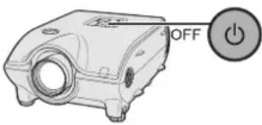 | Unplug the power cord from the AC socket.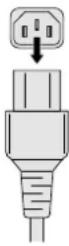 | Turn over the projector. Press the tab and lift open the filter cover in the direction of the arrow.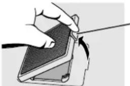 ·Tab ·Tab | Grasp the air filter between your fingers and lift it out of the filter cover.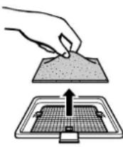 |
| 5 Replace the air filter. Replace the filter cover. | 7 Remove the lamp cage cover. | |
Place the air filter underneath the tabs on the filter frame.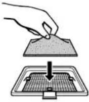 | Insert the tab on the end of the filter cover into the filter cover opening and press the filter cover into position.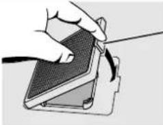 Tab Tab | Turn over the projector and loosen the user service screw that secures the lamp cage cover. Then slide the cover in the direction of the arrow.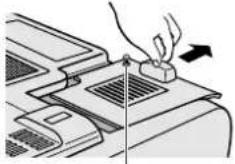 User service screw User service screw |
| 8 Remove the lamp cage. | 9 Insert the new lamp cage. | 10 Attach the lamp cage cover. |
Remove the securing screws from the lamp cage. Hold the lamp cage by the handle and pull it towards you.Securi curing scri ews 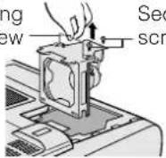 | Press the lamp cage firmly into the lamp cage compartment.Fasten the securing screws.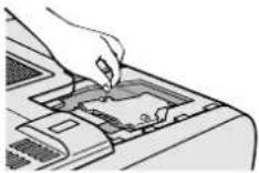 | Slide the lamp cage cover in the direction of the arrow. Then tighten the user service screw.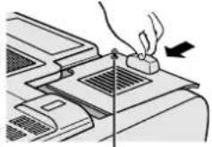 User service screw User service screw |
Resetting the lamp timer
| 1 Connect the power cord. | 2 Reset the lamp timer. | |
Plug the power cord into the AC socket of the projector.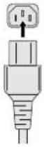 | While pressing ▼, ▶ and ENTER on the projector, press POWER ON on the projector.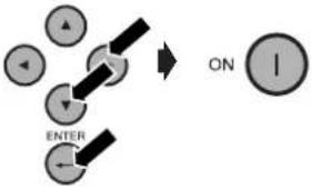 | “LAMP 0000H” is displayed, indicating that the lamp timer is reset.  |
NOTE
- Reset the lamp timer only after replacing the lamp.

Replacing the Air Filter
- This projector is equipped with two air filters to ensure the optimal operating condition of the projector.
- The air filters should be cleaned every 100 hours of use. Clean the filters more often when the projector is used in a dusty or smoky location.
- Have your nearest Sharp Authorized LCD Projector Dealer or Service Center exchange the filter (PFILD0080CEZZ) when it is no longer possible to clean it.
Bottom View
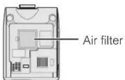
text_image
Air filterSide and Rear View
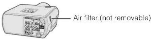
text_image
Air filter (not removable)Cleaning and replacing the bottom air filter
| 1 Turn off the power and disconnect the power cord. | 2 Remove the bottom filter cover. | 3 Remove the air filter. |
Press POWER OFF. Wait until the cooling fan stops.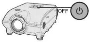 | Turn over the projector. Press the tab and lift open the filter cover in the direction of the arrow.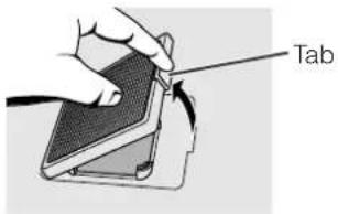 | Grasp the air filter between your fingers and lift it out of the filter cover. |
| 4 Clean the air filter. | 5 Replace the air filter. | 6 Replace the filter cover. |
Clean the dust off the air filter and cover with a vacuum cleaner extension hose.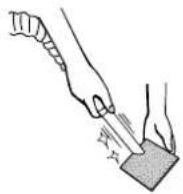 | Place the air filter underneath the tabs on the filter frame.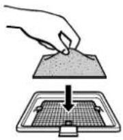 | Insert the tab on the end of the filter cover into the filter cover opening and press the filter cover into position.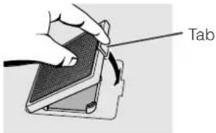 |
NOTE
- Be sure the filter cover is securely installed. The power will not turn on unless it is correctly installed.
Cleaning the side air filter (not removable)
If dust or dirt has collected inside the air filter, clean the filter with a vacuum cleaner extension hose.
NOTE
- The side air filter cannot be removed.

Troubleshooting
| Problem | Check |
| Power cannot be turned on or off using the POWER buttons (ON/OFF) on the projector. | Keylock level is set to "Level A" or "Level B", preventing operation of some or all buttons. (See page 52.) |
| Cannot be operated by remote control. | Check to see if the batteries are dead. If they are, replace with new ones. (See page 14.)When the projector is set to slave, use the buttons on the master projector or change the setting by RS-232C commands from the computer. (See page 52.) |
| Cannot be operated by all buttons of the projector and remote control. | When using slave setting in combination with Keylock Level B, all the buttons on the projector and the remote control are disabled. Use the SAPS or RS-232C commands to release slave and Keylock setting and enable buttons to operate. Without a computer, you can release slave and Keylock setting by entering the buttons on the projector as follows.ON→ ENTER → ON→ ENTER → ON→ ENTER → MENUHowever, this operation also releases the password set. |
| No picture and no sound. | Projector power cord is not plugged into the wall outlet.The bottom filter cover is not securely installed.Selected input is wrong. (See page 31.)Cables incorrectly connected to rear panel of the projector. (See pages 16–21.)Remote control batteries have run down. (See page 14.) |
| Sound is heard but no picture appears. | Cables incorrectly connected to rear panel of the projector. (See pages 16–21.)“Contrast” and “Bright” adjustments are set to minimum position. (See page 41.)On-screen Display (“BLACK SCREEN”) is turned off and Black Screen function is turned on, creating a black image. (See page 32.) |
| Color is faded or poor. | “Color” and “Tint” adjustments are not correct. (See page 41.) |
| Picture is blurred. | Adjust the focus. (See page 24.)Projection distance is too long or too short to allow for proper focus. (See pages 25–29.) |
| Picture appears but no sound is heard. | Cables incorrectly connected to rear panel of the projector. (See pages 16–21.)Volume is set to minimum. (See page 31.) |
| No OSD appears. | OSD Display is set to “Level A” or “Level B”, preventing to display some or all On-screen Displays. (See page 48.) |
| An unusual sound is occasionally heard from the cabinet. | If the picture is normal, the sound is due to cabinet shrinkage caused by temperature changes. This will not affect operation or performance. |
| Maintenance indicator lights up. | Refer to “Lamp/Maintenance Indicators” on page 63. |
| Picture noise appears. | Adjust the “Phase” setting. (See page 43.)Noise may appear when used with certain computers. Set the NOISE FILTER to ON using the RS-232C command. (See pages 70–72.) |
| 480P images do not appear. | Set the resolution mode to 480P. (See page 44.) |
| Image is green on INPUT 1 or 2 COMPONENT.Image is pink (no green) on INPUT 1, 2 RGB. | Change the input signal type. (See page 41.) |
If you encounter any problems during setup or operation of this projector, first refer to the "Troubleshooting" section on page 67. If this operation manual does not answer your question, please contact the SHARP Service Department listed below.
U.S.A.
Sharp Electronics Corporation
1-888-GO-SHARP (1-888-467-4277)
lcdsupport@sharpsec.com
http://www.sharplcd.com
Canada
Sharp Electronics of Canada Ltd.
(905) 568-7140
http://www.sharp.ca
Mexico
Sharp Electronics Corporation Mexico Branch
(525) 716-9000
http://www.sharp.com.mx
Latin America
Sharp Electronics Corp. Latin American
Group
(305) 264-2277
www.servicio@sharpsec.com
http://www.siempresharp.com
Germany
Sharp Electronics (Europe) GMBH
01805-234675
http://www.sharp.de
U.K.
Sharp Electronics (U.K.) Ltd.
0161-205-2333
custinfo@sharp-uk.co.uk
http://www.sharp.co.uk
Italy
Sharp Electronics (Italy) S.P.A.
(39) 02-89595-1
http://www.sharp.it
France
Sharp Electronics France
01 49 90 35 40
hotlineced@sef.sharp-eu.com
http://www.sharp.fr
Spain
Sharp Electronica Espana, S.A.
93 5819700
sharplcd@sees.sharp-eu.com
http://www.sharp.es
Switzerland
cattaneo@sez.sharp-eu.com
http://www.sharp.ch
Sweden
Sharp Electronics ( Nordic ) AB
(46) 8 6343600
vision.support@sen.sharp-eu.com
http://www.sharp.se
Austria
Sharp Electronics Austria (Ges.m.b.H.)
0043 1 727 19 123
pogats@sea.sharp-eu.com
http://www.sharp.at
Australia
Sharp Corporation of Australia Pty.Ltd.
1300-135-022
http://www.sharp.net.au
New Zealand
Sharp Corporation of New Zealand
(09) 634-2059, (09) 636-6972
http://www.sharpnz.co.nz
Singapore
Sharp-Roxy Sales (S) Pte. Ltd.
65-226-6556
ckng@srs.global.sharp.co.jp
http://www.sharp.com.sg
Hong Kong
Sharp-Roxy (HK) Ltd.
(852) 2410-2623
dcmktg@srh.global.sharp.co.jp
http://www.sharp.com.hk
Malaysia
Sharp-Roxy Sales & Service Co.
(60) 3-5125678
U.A.E.
Sharp Middle East Fze
971-4-81-5311
helpdesk@smef.global.sharp.co.jp
Thailand
Sharp Thebnakorn Co. Ltd.
02-236-0170
svc@stcl.global.sharp.co.jp
http://www.sharp-th.com
Korea
Sharp Electronics Incorporated of Korea
(82) 2-3660-2002
webmaster@sharp-korea.co.kr
http://www.sharp-korea.co.kr
India
Sharp Business Systems (India) Limited
(91) 11-6431313
service@sharp-oa.com
INPUT 1 RGB and OUTPUT (INPUT 1, 2) Signal Ports: 15-pin Mini D-sub female connector
RGB Input
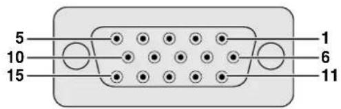
text_image
5 10 15 1 6 11Analog
| 1. Video input (red) | 8. Earth (blue) |
| 2. Video input(green/sync on green) | 9. Not connected10. GND |
| 3. Video input (blue) | 11. GND |
| 4. Reserve input 1 | 12. Bi-directional data |
| 5. Composite sync | 13. Horizontal sync signal |
| 6. Earth (red) | 14. Vertical sync signal |
| 7. Earth (green/sync on green) | 15. Data clock |
Component Input
| Analog | |
| 1. PR (CR) | 9. Not connected |
| 2. Y | 10. Not connected |
| 3. PB (CB) | 11. Not connected |
| 4. Not connected | 12. Not connected |
| 5. Not connected | 13. Not connected |
| 6. Earth (PR) | 14. Not connected |
| 7. Earth (Y) | 15. Not connected |
| 8. Earth (PB) | |
RS-232C Port: 9-pin D-sub male connector
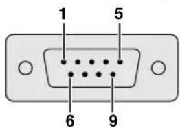
text_image
1 5 6 9Pin No. Signal Name I/O Reference
| 1 CD Not connected | ||
| 2 RD Receive Data Input Connected to internal circuit | ||
| 3 SD Send Data Output Connected to internal circuit | ||
| 4 ER Not connected | ||
| 5 SG Signal Ground Connected to internal circuit | ||
| 6 DR Data Set Ready | Not connected | |
| 7 RS Request to Send | Output Connected to internal circuit | |
| 8 CS Clear to Send | Input | Connected to internal circuit |
| 9 CI | Not connected | |
RS-232C Cable recommended connection: 9-pin D-sub female connector
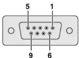
text_image
5 1 9 6Pin No. Signal
| 1 | CD | 1 | CD |
| 2 | RD | 2 | RD |
| 3 | SD | 3 | SD |
| 4 | ER | 4 | ER |
| 5 | SG | 5 | SG |
| 6 | DR | 6 | DR |
| 7 | RS | 7 | RS |
| 8 | CS | 8 | CS |
| 9 | CI | 9 | CI |
NOTE
- Depending on the system layout, it is necessary to connect Pin 4 and Pin 6 on the controlling device (e.g. PC).
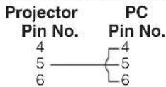
INPUT 3 DVI Port: 29-pin
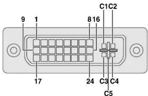
text_image
9 1 8 16 C1 C2 17 24 C3 C4 C5Pin No.
| 1 | T.M.D.S. Data 2- | 16 | Hot Plug Detect |
| 2 | T.M.D.S. Data 2+ | 17 | T.M.D.S. Data 0- |
| 3 | T.M.D.S. Data 2/4 Shield | 18 | T.M.D.S. Data 0+ |
| 4 | T.M.D.S. Data 4- ^*3 | 19 | T.M.D.S. Data 0/5 Shield |
| 5 | T.M.D.S. Data 4+ ^*3 | 20 | T.M.D.S. Data 5- ^*3 |
| 6 | DDC Clock | 21 | T.M.D.S. Data 5+ ^*3 |
| 7 | DDC Data | 22 | T.M.D.S. Clock Shield |
| 8 | Analog Vertical Sync | 23 | T.M.D.S. Clock + |
| 9 | T.M.D.S. Data 1- | 24 | T.M.D.S. Clock - |
| 10 | T.M.D.S. Data 1+ | C1 | Analog Red |
| 11 | T.M.D.S. Data 1/3 Shield | C2 | Analog Green |
| 12 | T.M.D.S. Data 3- ^*3 | C3 | Analog Blue |
| 13 | T.M.D.S. Data 3+ ^*3 | C4 | Analog Horizontal sync |
| 14 | +5 V Power | C5 | Analog Ground ^*2 |
| 15 | Ground ^*1 |
NOTE
• * 1 Return for +5 V, Hsync. and Vsync.
• * 2 Analog R, G and B return
• * 3 These pins are not used on this equipment.
PC control
A computer can be used to control the projector by connecting an RS-232C cable (cross type, sold separately) to the projector. (See page 20 for connection.)
Communication conditions
Set the serial port settings of the computer to match that of the table.
Signal format: Conforms to RS-232C standard.
Baud rate: 9,600 bps
Data length: 8 bits
Parity bit: None
Stop bit: 1 bit
Flow control: None
Basic format
Commands from the computer are sent in the following order: command, parameter, and return code. After the projector processes the command from the computer, it sends a response code to the computer.
Command format

text_image
C1 C2 C3 C4 P1 P2 P3 P4 Command 4-digit Parameter 4-digit Return code (0DH)Response code format
Normal response

Problem response (communication error or incorrect command)

When more than one code is being sent, send each command only after the OK response code for the previous command from the projector is verified.
NOTE
- When using the computer control function of the projector, the projector operating status cannot be read to the computer. Therefore, confirm the status by transmitting the display commands for each adjustment menu and checking the status with the On-screen Display. If the projector receives a command other than a menu display command, it will execute the command without displaying the On-screen Display.
- When the projector is in standby mode, send each command more than 1 minute after the previous command.
Commands

- When "BRIGHT" of INPUT 1 (RGB 1) image adjustment is set to -10.
ProjectorComputer
| R | A | B | R | 1 | 0 | - | O | K |
| CONTROLS CONTENTS | COMMAID | PARAMETER | RETURN | ||||||||
| POWER ON | P | O | W | R | _ | 1 | OK OR ERR | ||||
| POWER OFF | P | O | W | R | _ | 0 | OK OR ERR | ||||
| VOLUME (0 – 60) | V | O | L | A | _ | * | * | OK OR ERR | |||
| MUTE ON | M | U | T | E | _ | 1 | OK OR ERR | ||||
| MUTE OFF | M | U | T | E | _ | 0 | OK OR ERR | ||||
| LENS FOCUS (–30 – +30) | L | N | F | O | _ | * | * | * | OK OR ERR | ||
| LENS ZOOM (–30 – +30) | L | N | Z | O | _ | * | * | * | OK OR ERR | ||
| KEYSTONE (–127 – +127) | K | E | Y | S | * | * | * | * | OK OR ERR | ||
| V-SIZE (–30 – +30) | V | S | I | Z | _ | * | * | OK OR ERR | |||
| DIGITAL SHIFT (–98 – +96) | L | N | D | S | _ | * | * | * | OK OR ERR | ||
| CONTROLS CONTENTS | COMMAND | PARAMETER | RETURN | ||||||
| BUTTONS & REMOTE CONTROL KEY | BLACK SCREEN ON | I | M | B | K | _ | _ | 1 | OK OR ERR |
| BLACK SCREEN OFF | I | M | B | K | _ | _ | 0 | OK OR ERR | |
| INPUT 1 (RGB 1) | I | R | G | B | _ | _ | 1 | OK OR ERR | |
| INPUT 2 (RGB 2) | I | R | G | B | _ | _ | 2 | OK OR ERR | |
| INPUT 3 (RGB 3) | I | R | G | B | _ | _ | 3 | OK OR ERR | |
| INPUT 4 (VIDEO 1) | I | V | E | D | _ | _ | 1 | OK OR ERR | |
| INPUT 5 (VIDEO 2) | I | V | E | D | _ | _ | 2 | OK OR ERR | |
| INPUT CHECK | I | C | H | K | _ | _ | 0 | OK OR ERR | |
| FREEZE ON | F | R | E | Z | _ | _ | 1 | OK OR ERR | |
| FREEZE OFF | F | R | E | Z | _ | _ | 0 | OK OR ERR | |
| AUTO SYNC START | A | D | J | S | _ | _ | 1 | OK OR ERR | |
| BUTTONS & REMOTE CONTROL KEYPICTURE | INPUT 1 (RGB 1) RESIZE : NORMAL | R | A | S | R | _ | _ | 1 OK OR ERR | |
| INPUT 1 (RGB 1) RESIZE : FULL | R | A | S | R | _ | _ | 5 OK OR ERR | ||
| INPUT 1 (RGB 1) RESIZE : DOT BY DOT | R | A | S | R | _ | _ | 3 OK OR ERR | ||
| INPUT 2 (RGB 2) RESIZE : NORMAL | R | B | S | R | _ | _ | 1 OK OR ERR | ||
| INPUT 2 (RGB 2) RESIZE : FULL | R | B | S | R | _ | _ | 5 OK OR ERR | ||
| INPUT 2 (RGB 2) RESIZE : DOT BY DOT | R | B | S | R | _ | _ | 3 OK OR ERR | ||
| INPUT 3 (RGB 3) RESIZE : NORMAL | R | C | S | R | _ | _ | 1 OK OR ERR | ||
| INPUT 3 (RGB 3) RESIZE : FULL | R | C | S | R | _ | _ | 5 OK OR ERR | ||
| INPUT 3 (RGB 3) RESIZE : DOT BY DOT | R | C | S | R | _ | _ | 3 OK OR ERR | ||
| INPUT 4 (VIDEO 1) RESIZE : NORMAL | R | A | S | V | _ | _ | 1 OK OR ERR | ||
| INPUT 4 (VIDEO 1) RESIZE : FULL | R | A | S | V | _ | _ | 5 OK OR ERR | ||
| INPUT 4 (VIDEO 1) RESIZE : BORDER | R | A | S | V | _ | _ | 3 OK OR ERR | ||
| INPUT 4 (VIDEO 1) RESIZE : STRETCH | R | A | S | V | _ | _ | 2 OK OR ERR | ||
| INPUT 4 (VIDEO 1) RESIZE : SMART STRETCH | R | A | S | V | _ | _ | 4 OK OR ERR | ||
| INPUT 5 (VIDEO 2) RESIZE : NORMAL | R | B | S | V | _ | _ | 1 OK OR ERR | ||
| INPUT 5 (VIDEO 2) RESIZE : FULL | R | B | S | V | _ | _ | 5 OK OR ERR | ||
| INPUT 5 (VIDEO 2) RESIZE : BORDER | R | B | S | V | _ | _ | 3 OK OR ERR | ||
| INPUT 5 (VIDEO 2) RESIZE : STRETCH | R | B | S | V | _ | _ | 2 OK OR ERR | ||
| INPUT 5 (VIDEO 2) RESIZE : SMART STRETCH | R | B | S | V | _ | _ | 4 OK OR ERR | ||
| RCB GAMMA : STANDARD | G | A | M | R | _ | _ | 1 OK OR ERR | ||
| RGB GAMMA : PRESENTATION | G | A | M | R | _ | _ | 2 OK OR ERR | ||
| RCB GAMMA : CINEMA | G | A | M | R | _ | _ | 3 OK OR ERR | ||
| RGB GAMMA : CUSTOM | G | A | M | R | _ | _ | 4 OK OR ERR | ||
| VIDEO GAMMA : STANDARD | G | A | M | V | _ | _ | 1 OK OR ERR | ||
| VIDEO GAMMA : PRESENTATION | G | A | M | V | _ | _ | 2 OK OR ERR | ||
| VIDEO GAMMA : CINEMA | G | A | M | V | _ | _ | 3 OK OR ERR | ||
| VIDEO GAMMA : CUSTOM | G | A | M | V | _ | _ | 4 OK OR ERR | ||
| INPUT 1 (RGB 1) CONTRAST (-30 - +30) | R | A | P | I | _ | * * * | OK OR ERR | ||
| INPUT 1 (RGB 1) BRIGHT (-30 - +30) | R | A | B | R | _ | * * * | OK OR ERR | ||
| INPUT 1 (RGB 1) RED (-30 - +30) | R | A | R | D | _ | * * * | OK OR ERR | ||
| INPUT 1 (RGB 1) BLUE (-30 - +30) | R | A | B | E | _ | * * * | OK OR ERR | ||
| INPUT 1 (RGB 1) COLOR (-30 - +30) | R | A | C | O | _ | * * * | OK OR ERR | ||
| INPUT 1 (RGB 1) TINT (-30 - +30) | R | A | T | I | _ | * * * | OK OR ERR | ||
| INPUT 1 (RGB 1) SHARP (-30 - +30) | R | A | S | H | _ | * * * | OK OR ERR | ||
| INPUT 1 (RGB 1) CLR TEMP (-3 - +3) | R | A | C | T | _ | * * | OK OR ERR | ||
| INPUT 1 (RGB 1) DISPLAY | R | A | R | E | _ | _ | 0 OK OR ERR | ||
| INPUT 1 (RGB 1) ADJUSTMENT RESET | R | A | R | E | _ | _ | 1 OK OR ERR | ||
| INPUT 2 (RGB 2) CONTRAST (-30 - +30) | R | B | P | I | _ | * * * | OK OR ERR | ||
| INPUT 2 (RGB 2) BRIGHT (-30 - +30) | R | B | B | R | _ | * * * | OK OR ERR | ||
| INPUT 2 (RGB 2) RED (-30 - +30) | R | B | R | D | _ | * * * | OK OR ERR | ||
| INPUT 2 (RGB 2) BLUE (-30 - +30) | R | B | B | E | _ | * * * | OK OR ERR | ||
| INPUT 2 (RGB 2) COLOR (-30 - +30) | R | B | C | O | _ | * * * | OK OR ERR | ||
| INPUT 2 (RGB 2) TINT (-30 - +30) | R | B | T | I | _ | * * * | OK OR ERR | ||
| INPUT 2 (RGB 2) SHARP (-30 - +30) | R | B | S | H | _ | * * * | OK OR ERR | ||
| INPUT 2 (RGB 2) CLR TEMP (-3 - +3) | R | B | C | T | _ | * * | OK OR ERR | ||
| INPUT 2 (RGB 2) DISPLAY | R | B | R | E | _ | _ | 0 OK OR ERR | ||
| INPUT 2 (RGB 2) ADJUSTMENT RESET | R | B | R | E | _ | _ | 1 OK OR ERR | ||
| INPUT 3 (RGB 3) CONTRAST (-30 - +30) | R | C | P | I | _ | * * * | OK OR ERR | ||
| INPUT 3 (RGB 3) BRIGHT (-30 - +30) | R | C | B | R | _ | * * * | OK OR ERR | ||
| INPUT 3 (RGB 3) RED (-30 - +30) | R | C | R | D | _ | * * * | OK OR ERR | ||
| INPUT 3 (RGB 3) BLUE (-30 - +30) | R | C | B | E | _ | * * * | OK OR ERR | ||
| INPUT 3 (RGB 3) COLOR (-30 - +30) | R | C | C | O | _ | * * * | OK OR ERR | ||
| INPUT 3 (RGB 3) TINT (-30 - +30) | R | C | T | I | _ | * * * | OK OR ERR | ||
| INPUT 3 (RGB 3) SHARP (-30 - +30) | R | C | C | H | _ | * * * | OK OR ERR | ||
| INPUT 3 (RGB 3) CLR TEMP (-3 - +3) | R | C | C | T | _ | * * | OK OR ERR | ||
| INPUT 3 (RGB 3) DISPLAY | R | C | R | E | _ | _ | 0 OK OR ERR | ||
| INPUT 3 (RGB 3) ADJUSTMENT RESET | R | C | R | E | _ | _ | 1 OK OR ERR | ||
| CONTROL CONTENTS | COMMAND | PARAMETER | RETURN | |||||||
| PICTUREFINE SYNC | INPUT 1 (RGB 1) SIGNAL TYPE : RGB | I | A | S | I | — | — | — | 1 | OK OR ERR |
| INPUT 1 (RGB 1) SIGNAL TYPE : COMPONENT | I | A | S | I | — | — | — | 2 | OK OR ERR | |
| INPUT 2 (RGB 2) SIGNAL TYPE : RGB | I | B | S | I | — | — | — | 1 | OK OR ERR | |
| INPUT 2 (RGB 2) SIGNAL TYPE : COMPONENT | I | B | S | I | — | — | — | 2 | OK OR ERR | |
| INPUT 1 (RGB 1) 2D PROGRESSIVE | R | A | I | P | — | — | — | 0 | OK OR ERR | |
| INPUT 1 (RGB 1) 3D PROGRESSIVE | R | A | I | P | — | — | — | 1 | OK OR ERR | |
| INPUT 1 (RGB 1) Film MODE | R | A | I | P | — | — | — | 2 | OK OR ERR | |
| INPUT 2 (RGB 2) 2D PROGRESSIVE | R | B | I | P | — | — | — | 0 | OK OR ERR | |
| INPUT 2 (RGB 2) 3D PROGRESSIVE | R | B | I | P | — | — | — | 1 | OK OR ERR | |
| INPUT 2 (RGB 2) Film MODE | R | B | I | P | — | — | — | 2 | OK OR ERR | |
| INPUT 3 (RGB 3) 2D PROGRESSIVE | R | C | I | P | — | — | — | 0 | OK OR ERR | |
| INPUT 3 (RGB 3) 3D PROGRESSIVE | R | C | I | P | — | — | — | 1 | OK OR ERR | |
| INPUT 3 (RGB 3) Film MODE | R | C | I | P | — | — | — | 2 | OK OR ERR | |
| INPUT 4 (VIDEO 1) CONTRAST (-30 - +30) | V | A | P | I | — | * | * | * | OK OR ERR | |
| INPUT 4 (VIDEO 1) BRIGHT (-30 - +30) | V | A | B | R | — | * | * | * | OK OR ERR | |
| INPUT 4 (VIDEO 1) RED (-30 - +30) | V | A | R | D | — | * | * | * | OK OR ERR | |
| INPUT 4 (VIDEO 1) BLUE (-30 - +30) | V | A | B | E | — | * | * | * | OK OR ERR | |
| INPUT 4 (VIDEO 1) COLOR (-30 - +30) | V | A | C | O | — | * | * | * | OK OR ERR | |
| INPUT 4 (VIDEO 1) TINT (-30 - +30) | V | A | T | I | — | * | * | * | OK OR ERR | |
| INPUT 4 (VIDEO 1) SHARP (-30 - +30) | V | A | S | H | — | * | * | * | OK OR ERR | |
| INPUT 4 (VIDEO 1) CLR TEMP (-3 - +3) | V | A | C | T | — | — | * | * | OK OR ERR | |
| INPUT 4 (VIDEO 1) DISPLAY | V | A | R | E | — | — | — | 0 | OK OR ERR | |
| INPUT 4 (VIDEO 1) ADJUSTMENT RESET | V | A | R | E | — | — | — | 1 | OK OR ERR | |
| INPUT 5 (VIDEO 2) CONTRAST (-30 - +30) | V | B | P | I | — | * | * | * | OK OR ERR | |
| INPUT 5 (VIDEO 2) BRIGHT (-30 - +30) | V | B | B | R | — | * | * | * | OK OR ERR | |
| INPUT 5 (VIDEO 2) RED (-30 - +30) | V | B | R | D | — | * | * | * | OK OR ERR | |
| INPUT 5 (VIDEO 2) BLUE (-30 - +30) | V | B | B | E | — | * | * | * | OK OR ERR | |
| INPUT 5 (VIDEO 2) COLOR (-30 - +30) | V | B | C | O | — | * | * | * | OK OR ERR | |
| INPUT 5 (VIDEO 2) TINT (-30 - +30) | V | B | T | I | — | * | * | * | OK OR ERR | |
| INPUT 5 (VIDEO 2) SHARP (-30 - +30) | V | B | S | H | — | * | * | * | OK OR ERR | |
| INPUT 5 (VIDEO 2) CLR TEMP (-3 - +3) | V | B | C | T | — | — | * | * | OK OR ERR | |
| INPUT 5 (VIDEO 2) DISPLAY | V | B | R | E | — | — | — | 0 | OK OR ERR | |
| INPUT 5 (VIDEO 2) ADJUSTMENT RESET | V | B | R | E | — | — | — | 1 | OK OR ERR | |
| INPUT 4 (VIDEO 1) 2D PROGRESSIVE | V | A | I | P | — | — | — | 0 | OK OR ERR | |
| INPUT 4 (VIDEO 1) 3D PROGRESSIVE | V | A | I | P | — | — | — | 1 | OK OR ERR | |
| INPUT 4 (VIDEO 1) Film MODE | V | A | I | P | — | — | — | 2 | OK OR ERR | |
| INPUT 5 (VIDEO 2) 2D PROGRESSIVE | V | B | I | P | — | — | — | 0 | OK OR ERR | |
| INPUT 5 (VIDEO 2) 3D PROGRESSIVE | V | B | I | P | — | — | — | 1 | OK OR ERR | |
| INPUT 5 (VIDEO 2) Film MODE | V | B | I | P | — | — | — | 2 | OK OR ERR | |
| (INPUT 1-5) 2D PROGRESSIVE | I | M | I | P | — | — | — | 0 | OK OR ERR | |
| (INPUT 1-5) 3D PROGRESSIVE | I | M | I | P | — | — | — | 1 | OK OR ERR | |
| (INPUT 1-5) Film MODE | I | M | I | P | — | — | — | 2 | OK OR ERR | |
| CLOCK (-150 - +150) | I | N | C | L | * | * | * | * | OK OR ERR | |
| PHASE (-60 - +60) | I | N | P | H | — | * | * | * | OK OR ERR | |
| H-POSITION (-150 - +150) | I | A | H | P | * | * | * | * | OK OR ERR | |
| V-POSITION (-60 - +60) | I | A | V | P | — | * | * | * | OK OR ERR | |
| RGB INPUT DISPLAY | I | A | R | E | — | — | — | 0 | OK OR ERR | |
| RGB ADJUSTMENT RESET | I | A | R | E | — | — | — | 1 | OK OR ERR | |
| SAVE SETTING (1 - 7) | M | E | M | S | — | — | — | * | OK OR ERR | |
| SELECT SETTING (1 - 7) | M | E | M | L | — | — | — | * | OK OR ERR | |
| RGB HORIZONTAL FREQUENCY CHECK | T | F | R | Q | — | — | — | 1 | kHz (***, * OR_) | |
| RGB VERTICAL FREQUENCY CHECK | T | F | R | Q | — | — | — | 2 | Hz (***, * OR_) | |
| AUTO SYNC OFF | A | A | D | J | — | — | — | 0 | OK OR ERR | |
| NORMAL AUTO SYNC | A | A | D | J | — | — | — | 1 | OK OR ERR | |
| HIGH SPEED AUTO SYNC | A | A | D | J | — | — | — | 2 | OK OR ERR | |
| AUTO SYNC DISPLAY ON | I | M | A | S | — | — | — | 1 | OK OR ERR | |
| AUTO SYNC DISPLAY OFF | I | M | A | S | — | — | — | 0 | OK OR ERR | |
| AUDIOPTIONS (1) | CONTROL CONTENTS | COMMAND | PARAMETER | RETURN | ||||||
| BALANCE (-30 - +30) | A | A | B | L | _ | * | * | OK OR ERR | ||
| TREBLE (-30 - +30) | A | A | T | E | _ | * | * | OK OR ERR | ||
| BASS (-30 - +30) | A | A | B | A | _ | * | * | OK OR ERR | ||
| AUDIO DISPLAY | A | A | R | E | _ | _ | 0 | OK OR ERR | ||
| AUDIO ADJUSTMENT RESET | A | A | R | E | _ | _ | 1 | OK OR ERR | ||
| FAO | A | O | U | T | _ | _ | 1 | OK OR ERR | ||
| VAO | A | O | U | T | _ | _ | 2 | OK OR ERR | ||
| SPEAKER ON | A | S | P | K | _ | _ | 1 | OK OR ERR | ||
| SPEAKER OFF | A | S | P | K | _ | _ | 0 | OK OR ERR | ||
| PICT IN PICT : BOTTOM RIGHT | P | I | N | P | _ | 1 | 1 | OK OR ERR | ||
| PICT IN PICT : BOTTOM LEFT | P | I | N | P | _ | 1 | 2 | OK OR ERR | ||
| PICT IN PICT : UPPER RIGHT | P | I | N | P | _ | 1 | 3 | OK OR ERR | ||
| PICT IN PICT : UPPER LEFT | P | I | N | P | _ | 1 | 4 | OK OR ERR | ||
| PICT IN PICT RESET | P | I | N | P | _ | _ | 0 | OK OR ERR | ||
| VIDEO DNR OFF | 3 | D | N | R | _ | _ | 0 | OK OR ERR | ||
| VIDEO DNR ON | 3 | D | N | R | _ | _ | 1 | OK OR ERR | ||
| OSD DISPLAY ON | I | M | D | I | _ | _ | 1 | OK OR ERR | ||
| OSD DISPLAY OFF (LEVEL A) | I | M | D | I | _ | _ | 2 | OK OR ERR | ||
| OSD DISPLAY OFF (LEVEL B) | I | M | D | I | _ | _ | 0 | OK OR ERR | ||
| BLACK SCREEN DISPLAY ON | I | M | B | O | _ | _ | 1 | OK OR ERR | ||
| BLACK SCREEN DISPLAY OFF | I | M | B | O | _ | _ | 0 | OK OR ERR | ||
| VIDEO SYSTEM SELECTION : AUTO | M | E | S | Y | _ | _ | 1 | OK OR ERR | ||
| VIDEO SYSTEM SELECTION : PAL | M | E | S | Y | _ | _ | 2 | OK OR ERR | ||
| VIDEO SYSTEM SELECTION : SECAM | M | E | S | Y | _ | _ | 3 | OK OR ERR | ||
| VIDEO SYSTEM SELECTION : NTSC4.43 | M | E | S | Y | _ | _ | 4 | OK OR ERR | ||
| VIDEO SYSTEM SELECTION : NTSC3.58 | M | E | S | Y | _ | _ | 5 | OK OR ERR | ||
| VIDEO SYSTEM SELECTION : PAL_M | M | E | S | Y | _ | _ | 6 | OK OR ERR | ||
| VIDEO SYSTEM SELECTION : PAL_N | M | E | S | Y | _ | _ | 7 | OK OR ERR | ||
| BACKGROUND SELECTION : SHARP | I | M | B | G | _ | _ | 1 | OK OR ERR | ||
| BACKGROUND SELECTION : CUSTOM | I | M | B | G | _ | _ | 2 | OK OR ERR | ||
| BACKGROUND SELECTION : BLUE | I | M | B | G | _ | _ | 3 | OK OR ERR | ||
| BACKGROUND SELECTION : NONE | I | M | B | G | _ | _ | 4 | OK OR ERR | ||
| STARTUP IMAGE SELECTION : SHARP | I | M | S | I | _ | _ | 1 | OK OR ERR | ||
| STARTUP IMAGE SELECTION : CUSTOM | I | M | S | I | _ | _ | 2 | OK OR ERR | ||
| STARTUP IMAGE SELECTION : NONE | I | M | S | I | _ | _ | 3 | OK OR ERR | ||
| POWER SAVE MODE: STANDARD | T | H | M | D | _ | _ | 0 | OK OR ERR | ||
| POWER SAVE MODE: LOW POWER | T | H | M | D | _ | _ | 1 | OK OR ERR | ||
| MONITOR OUT OFF | M | O | U | T | _ | _ | 0 | OK OR ERR | ||
| MONITOR OUT ON | M | O | U | T | _ | _ | 1 | OK OR ERR | ||
| AUTO POWER OFF : NO USE | A | P | O | W | _ | _ | 0 | OK OR ERR | ||
| AUTO POWER OFF : USE | A | P | O | W | _ | _ | 1 | OK OR ERR | ||
| CONTROLS CONTENTS | COMMAND | PARAMETER | RETURN | ||||||
| OPTIONS (2)LANGUAGE | LAMP USAGE TIME | T | L | T | T | _ | _ | 1 | 0-9999 (INTEGER) |
| LAMP STATUS | T | L | P | S | _ | _ | 1 | 0:OFF, 1:ON, 2:RETRY,3:WAITING, 4:LAMP ERROR | |
| PRJ MODE : REVERSE OFF | I | M | R | E | _ | _ | 0 | OK OR ERR | |
| PRJ MODE : REVERSE ON | I | M | R | E | _ | _ | 1 | OK OR ERR | |
| PRJ MODE : INVERT OFF | I | M | I | N | _ | _ | 0 | OK OR ERR | |
| PRJ MODE : INVERT ON | I | M | I | N | _ | _ | 1 | OK OR ERR | |
| STACK SETTING : NORMAL | S | T | A | K | _ | _ | 0 | OK OR ERR | |
| STACK SETTING : MASTER | S | T | A | K | _ | _ | 1 | OK OR ERR | |
| STACK SETTING : SLAVE | S | T | A | K | _ | _ | 2 | OK OR ERR | |
| KEYLOCK LEVEL : NORMAL | K | E | Y | L | _ | _ | 0 | OK OR ERR | |
| KEYLOCK LEVEL : LEVEL A | K | E | Y | L | _ | _ | 1 | OK OR ERR | |
| KEYLOCK LEVEL : LEVEL B | K | E | Y | L | _ | _ | 2 | OK OR ERR | |
| SET INPUTS : INPUT 1 NO USE | R | A | S | I | _ | _ | 0 | OK OR ERR | |
| SET INPUTS : INPUT 1 USE | R | A | S | I | _ | _ | 1 | OK OR ERR | |
| SET INPUTS : INPUT 2 NO USE | R | B | S | I | _ | _ | 0 | OK OR ERR | |
| SET INPUTS : INPUT 2 USE | R | B | S | I | _ | _ | 1 | OK OR ERR | |
| SET INPUTS : INPUT 3 NO USE | R | C | S | I | _ | _ | 0 | OK OR ERR | |
| SET INPUTS : INPUT 3 USE | R | C | S | I | _ | _ | 1 | OK OR ERR | |
| SET INPUTS : INPUT 4 NO USE | V | A | S | I | _ | _ | 0 | OK OR ERR | |
| SET INPUTS : INPUT 4 USE | V | A | S | I | _ | _ | 1 | OK OR ERR | |
| SET INPUTS : INPUT 5 NO USE | V | B | S | I | _ | _ | 0 | OK OR ERR | |
| SET INPUTS : INPUT 5 USE | V | B | S | I | _ | _ | 1 | OK OR ERR | |
| ID NO. CHECK | R | D | I | D | _ | _ | 1 | 001-250 | |
| LANGUAGE SELECTION : ENGLISH | M | E | L | A | _ | _ | 0 | OK OR ERR | |
| LANGUAGE SELECTION : DEUTSCH | M | E | L | A | _ | _ | 1 | OK OR ERR | |
| LANGUAGE SELECTION : ESPANOL | M | E | L | A | _ | _ | 2 | OK OR ERR | |
| LANGUAGE SELECTION : NEDERLANDS | M | E | L | A | _ | _ | 3 | OK OR ERR | |
| LANGUAGE SELECTION : FRANÇAIS | M | E | L | A | _ | _ | 4 | OK OR ERR | |
| LANGUAGE SELECTION : ITALIANO | M | E | L | A | _ | _ | 5 | OK OR ERR | |
| LANGUAGE SELECTION : SVENSKA | M | E | L | A | _ | _ | 6 | OK OR ERR | |
| LANGUAGE SELECTION : 日本語 | M | E | L | A | _ | _ | 7 | OK OR ERR | |
| LANGUAGE SELECTION : PORTUGUES | M | E | L | A | _ | _ | 8 | OK OR ERR | |
| LANGUAGE SELECTION : 汉语 | M | E | L | A | _ | _ | 9 | OK OR ERR | |
| LANGUAGE SELECTION : 한국어 | M | E | L | A | _ | 1 | 0 | OK OR ERR | |
| MODEL NAME CHECK | M | N | R | D | _ | _ | 1 | MODEL NAME | |
| NOISE FILTER OFF | N | F | I | L | _ | _ | 0 | OK OR ERR | |
| NOISE FILTER ON | N | F | I | L | _ | _ | 1 | OK OR ERR | |
| SERIAL NO. CHECK * | S | N | R | D | _ | _ | 1 | SERIAL NO. | |
| PROJECTOR NAME SETTING * | P | J | N | A | _ | _ | 1 | OK OR ERR | |
| PROJECTOR NAME CHECK | P | J | N | A | _ | _ | 2 | PROJECTOR NAME | |
NOTE
- If an underbar (_) appears in the parameter column, enter a space. If an asterisk (*) appears, enter a value in the range indicated in brackets under CONTROL CONTENTS.
- ^1 FINE SYNC can only be set in the displayed RGB mode.
- ^2 Noise may appear when used with certain computers. Set the NOISE FILTER to ON using the RS-232C command.
- ^3 SERIAL NO. CHECK command is used to read out the 12 digits of serial No..
- ^4 After OK is returned, enter PROJECTOR NAME, up to 12-character memory. The PROJECTOR NAME in memory can then be output (confirmed).
Specifications of wired remote control input
- 3.5 ~mm minijack
• External: +5 V (1 A) - Internal: GND
Function and transmission codes
| CONTROL ITEM | SYSTEM CODE | DATA CODE | EXTERNAL CODE | ||||||||||||
| C1 | C2 | C3 | C4 | C5 | C6 | C7 | C8 | C9 | C10 | C11 | C12 | C13 | C14 | C15 | |
| ON | 1 | 0 | 1 | 1 | 0 | 0 | 1 | 1 | 0 | 1 | 0 | 1 | 0 | 1 | 0 |
| OFF | 1 | 0 | 1 | 1 | 0 | 0 | 1 | 1 | 0 | 1 | 0 | 0 | 1 | 1 | 0 |
| VOLUME + | 1 | 0 | 1 | 1 | 0 | 0 | 0 | 1 | 0 | 1 | 0 | 0 | 0 | 1 | 0 |
| VOLUME - | 1 | 0 | 1 | 1 | 0 | 1 | 0 | 1 | 0 | 1 | 0 | 0 | 0 | 1 | 0 |
| MUTE | 1 | 0 | 1 | 1 | 0 | 1 | 1 | 1 | 0 | 1 | 0 | 0 | 0 | 1 | 0 |
| MENU | 1 | 0 | 1 | 1 | 0 | 0 | 0 | 1 | 0 | 0 | 0 | 1 | 1 | 1 | 0 |
| LENS | 1 | 0 | 1 | 1 | 0 | 1 | 1 | 0 | 1 | 0 | 0 | 0 | 1 | 1 | 0 |
| BLACK SCREEN | 1 | 0 | 1 | 1 | 0 | 1 | 0 | 0 | 1 | 0 | 1 | 1 | 0 | 1 | 0 |
| ENTER | 1 | 0 | 1 | 1 | 0 | 1 | 1 | 1 | 0 | 1 | 0 | 1 | 0 | 1 | 0 |
| RESIZE | 1 | 0 | 1 | 1 | 0 | 0 | 1 | 1 | 1 | 1 | 0 | 1 | 0 | 1 | 0 |
| UNDO | 1 | 0 | 1 | 1 | 0 | 1 | 0 | 0 | 1 | 1 | 0 | 1 | 0 | 1 | 0 |
| Freeze | 1 | 0 | 1 | 1 | 0 | 1 | 0 | 1 | 1 | 0 | 0 | 0 | 1 | 1 | 0 |
| Break Timer | 1 | 0 | 1 | 1 | 0 | 0 | 0 | 1 | 0 | 1 | 1 | 0 | 1 | 1 | 0 |
| CONTROL ITEM | SYSTEM CODE | DATA CODE | EXTERNAL CODE | ||||||||||||
| C1 | C2 | C3 | C4 | C5 | C6 | C7 | C8 | C9 | C10 | C11 | C12 | C13 | C14 | C15 | |
| Enlarge + | 1 | 0 | 1 | 1 | 0 | 1 | 0 | 1 | 1 | 0 | 1 | 1 | 0 | 1 | 0 |
| Enlarge - | 1 | 0 | 1 | 1 | 0 | 1 | 0 | 1 | 1 | 0 | 1 | 0 | 1 | 1 | 0 |
| AUTO SYNC | 1 | 0 | 1 | 1 | 0 | 0 | 1 | 0 | 1 | 1 | 1 | 1 | 1 | 1 | 0 |
| ▲ | 1 | 0 | 1 | 1 | 0 | 0 | 0 | 1 | 1 | 1 | 0 | 0 | 1 | 1 | 0 |
| ▼ | 1 | 0 | 1 | 1 | 0 | 1 | 0 | 1 | 1 | 1 | 0 | 0 | 1 | 1 | 0 |
| ◀ | 1 | 0 | 1 | 1 | 0 | 0 | 0 | 0 | 0 | 1 | 0 | 1 | 0 | 1 | 0 |
| ▶ | 1 | 0 | 1 | 1 | 0 | 1 | 1 | 1 | 1 | 0 | 0 | 1 | 0 | 1 | 0 |
| GAMMA | 1 | 0 | 1 | 1 | 0 | 0 | 0 | 0 | 0 | 0 | 0 | 1 | 0 | 1 | 0 |
| INPUT 1 | 1 | 0 | 1 | 1 | 0 | 1 | 0 | 1 | 0 | 1 | 1 | 0 | 0 | 1 | 0 |
| INPUT 2 | 1 | 0 | 1 | 1 | 0 | 0 | 1 | 1 | 0 | 1 | 1 | 0 | 0 | 1 | 0 |
| INPUT 3 | 1 | 0 | 1 | 1 | 0 | 1 | 0 | 1 | 0 | 1 | 1 | 0 | 1 | 1 | 0 |
| INPUT 4 | 1 | 0 | 1 | 1 | 0 | 0 | 1 | 0 | 0 | 1 | 1 | 0 | 0 | 1 | 0 |
| INPUT 5 | 1 | 0 | 1 | 1 | 0 | 1 | 1 | 0 | 0 | 1 | 1 | 0 | 0 | 1 | 0 |
NOTE
- To operate the mouse, left-click and right-click functions through the wired remote control input, connect the cable from the WIRED REMOTE control input terminal on the projector to the remote control. The codes for these functions are complex and are, therefore, not listed here.
Wired remote control function code
LSB MSB
| C1 System Code C5 C6 Beta. Code | C13 C14 C16— — | |||||||||||||||||
| 1 | 0 | 1 | 1 | 0 | ' | ' | ' | ' | ' | ' | ' | ' | ' | ' | ' | ' | 1 | 0 |
- System codes C1 to C5 are fixed at "10110".
- Codes C14 and C15 are reverse confirmation bits, with "10" indicating "Front" and "01" indicating "Rear".
Sharp remote control signal format
Transmission format: 15-bit format

text_image
67.5 ms 67.5 msWave form of output signal: Output using Pulse Position Modulation

text_image
1 T1 T2 "1" "0" "0" "0" D "0" "0" 1 26.4 μs 1• t = 264 μs
- Pulse carrier frequency = 455/12 kHz
- T_0 = 1.05 ~ms
- Duty ratio = 1:1
- T_1 = 2.10 ~ms
Transmission control code
15 bit
| C1 | C2 | C3 | C4 | C5 | C6 | C7 | C8 | C9 | C10 | C11 | C12 | C13 | C14 | C15 |
| System Address | Function Key Data Bit | Data Expansion | Mask | Data Distr-Finition | ||||||||||
| D to D Common Data Bit | Reverse in D | |||||||||||||
Example of Reverse D to
| D | C1 | C2 | C3 | C4 | C5 | C6 | C7 | C8 | C9 | C10 | C11 | C12 | C13 | C14 | C15 |
| 1 | 0 | 1 | 1 | 0 | 1 | 0 | 0 | 0 | 0 | 0 | 0 | 0 | 1 | 0 |
Computer
Horizontal Frequency: 15–126 kHz* / Vertical Frequency: 43–200 Hz / Pixel Clock: 12–230 MHz Compatible with sync on green and composite sync signals UXGA and SXGA compatible in advanced intelligent compression or intelligent compression AICS (Advanced Intelligent Compression and Expansion System) resizing technology
| PC/MAC/WS | Resolution | Horizontal Frequency (kHz) | Vertical Frequency (Hz) | VESA Standard | DVI Support | Display | |
| PC | VGA | 640 × 350 | 27.0 60 | Upscale | |||
| 31.5 70 | |||||||
| 37.9 85 | √ | ||||||
| 720 × 350 | 27.0 60 | ||||||
| 31.5 70 | |||||||
| 640 × 400 | 27.0 60 | √ | |||||
| 31.5 70 | √ | ||||||
| 37.9 | 85 | √ | √ | ||||
| 720 × 400 | 27.0 | 60 | √ | ||||
| 31.5 | 70 | √ | |||||
| 37.9 | 85 | √ | √ | ||||
| 640 × 480 | 26.2 | 50 | |||||
| 31.5 | 60 | √ | |||||
| 34.7 | 70 | ||||||
| 37.9 | 72 | √ | √ | ||||
| 37.5 | 75 | √ | √ | ||||
| 43.3 | 85 | √ | √ | ||||
| 47.9 | 90 | ||||||
| 53.0 | 100 | ||||||
| 61.8 | 120 | ||||||
| 78.5 | 150 | ||||||
| 80.9 | 160 | ||||||
| 100.4 200 | |||||||
| SVGA | 800 × 600 | 31.4 50 | |||||
| 35.1 56 | √ | √ | |||||
| 37.9 60 | √ | √ | |||||
| 44.5 70 | |||||||
| 48.1 72 | √ | √ | |||||
| 46.9 75 | √ | √ | |||||
| 53.7 85 | √ | √ | |||||
| 56.8 90 | |||||||
| 64.0 100 | |||||||
| 77.2 120 | |||||||
| 98.3 150 | |||||||
| 102.1 160 | |||||||
| 125.6 200 | |||||||
| XGA | 1.024 × 768 | 35.5 43 | √ | True | |||
| 40.3 50 | |||||||
| 48.4 60 | √ | √ | |||||
| 56.5 70 | √ | √ | |||||
| 58.1 72 | |||||||
| 60.0 75 | √ | √ | |||||
| 68.7 85 | √ | √ | |||||
| 73.5 90 | |||||||
| 77.2 96 | |||||||
| 80.6 100 | |||||||
| 98.8 120 | |||||||
| 113.2 140 | |||||||
| PC/MAC/WS | Resolution Disp | Horizontal frequency (Hz) | Vertical Frequency (Hz) | VESA Standard | DVI Support | ||
| PC | SXGA | 1,152 × 864 | 54.3 60 | √ | Advanced Intelligent Compression | ||
| 64.0 70 | |||||||
| 64.1 72 | |||||||
| 67.5 75 | √ | √ | |||||
| 75.7 80 | |||||||
| 77.3 85 | |||||||
| 90.2 100 | |||||||
| 1,152 × 882 | 54.8 60 | ||||||
| 65.9 72 | |||||||
| 67.4 74 | |||||||
| 1,280 × 1,024 | 64.0 60 | √ | √ | ||||
| 74.6 70 | |||||||
| 78.1 74 | |||||||
| 80.0 75 | √ | ||||||
| 91.1 85 | √ | ||||||
| 108.4 100 | |||||||
| SXGA+ | 1,400 × 1,050 | 64.0 60 | |||||
| UXGA | 1,600 × 1,200 | 74.7 52 | |||||
| 75.0 60 | √ | ||||||
| 81.3 65 | √ | Intelligent Compression | |||||
| 87.5 70 | √ | ||||||
| 90.1 72 | |||||||
| 93.8 75 | √ | ||||||
| 106.3 85 | √ | ||||||
| PC/MAC 13' | VGA | 640 × 480 | 34.9 | 67 | Upscale | ||
| PC/MAC 19' | XGA | 1,024 × 768 | 48.4 60 | √ | √ | True | |
| 60.0 | 75 | √ | √ | ||||
| PC/MAC 21' | SXGA | 1,280 × 1,024 | 80.0 | 75 | √ | Advanced Intelligent Compression | |
| MAC 16' | SVGA | 800 × 600 | 46.8 75 | Upscale | |||
| 832 × 624 | 49.6 75 | ||||||
| MAC 21' | SXGA | 1,152 × 870 | 68.5 | 75 | Advanced Intelligent Compression | ||
| HP (WS) | SXGA | 1,280 × 1,024 | 78.1 72 | ||||
| PC (WS) | 1,280 × 960 | 60.0 60 | √ | ||||
| WS | 85.9 85 | ||||||
| SGI (WS) | 1,280 × 1,024 | 53.5 50 | |||||
| 76.8 72 | |||||||
| SUN (WS) | 1,152 × 900 | 60.9 66 | |||||
| 71.9 76 | |||||||
* When the RGB input is used for displaying moving images received as interlaced image signal, the images may not be displayed as you intended depending on the type of the signal. Please use the component input, video input, or s-video input in case this happens.
NOTE
- This projector may not be able to display images from notebook computers in simultaneous (CRT/LCD) mode. Should this occur, turn off the LCD display on the notebook computer and output the display data in "CRT only" mode. Details on how to change display modes can be found in your notebook computer's operation manual.
- This projector can receive 640 × 350 VESA format VGA signals, however, "640 × 400" will appear on the screen.
- When receiving 1,600 × 1,200 VESA format UXGA signals, sampling occurs and the image is displayed with 1,024 lines, causing part of the image to be blocked.
DTV
| Horizontal Frequency (kHz) | Sylindrical Frequency (Hz) | |
| 480I | 15.7 | 60 |
| 480P | 31.5 | 60 |
| 580I | 15.6 | 50 |
| 580P | 31.3 | 50 |
| 720P | 45.0 | 60 |
| 1035I | 33.6 | 60 |
| 1080I | 33.8 | 60 |
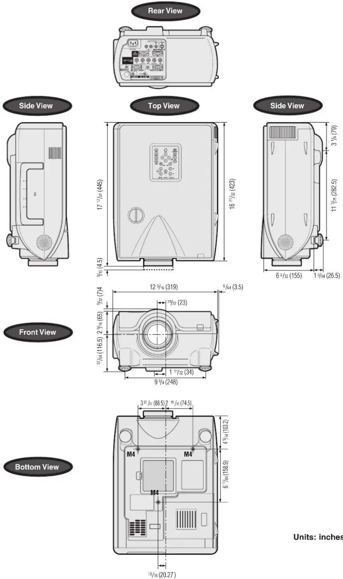
| Product type | LCD Projector |
| Model | XG-P25X |
| Video system | PAL/PAL 60/PAL-M/PAL-N/SECAM/NTSC 3.58/NTSC 4.43 |
| DTV 480I/480P/580I/580P/720P/1035I/1080I | |
| Display method | LCD panel × 3, RGB optical shutter method |
| LCD panel | Panel size: 1.3" (33mm) (20.0 [H] × 26.6 [W] mm) |
| Display method: Translucent TN liquid crystal panel | |
| Drive method: TFT (Thin Film Transistor) Active Matrix panel | |
| No. of dots: 786,432 dots (1,024 [H] × 768 [V]) | |
| Standard Lens | 1-1.3 × zoom lens, F1.7-2.4, f = 49.2-63.8 mm |
| Projection lamp | AC 270 W lamp |
| Video input signal | RCA Connector (INPUT 4): VIDEO, composite video, 1.0 Vp-p, sync negative, 75 Ω terminated |
| RCA Connector: AUDIO, 0.5 Vrms more than 22 kΩ (stereo) | |
| S-video input signal | 4-pin Mini DIN connector (INPUT 5) |
| Y (luminance signal): 1.0 Vp-p, sync negative, 75 Ω terminated | |
| C (chrominance signal): Burst 0.286 Vp-p, 75 Ω terminated | |
| Component input signal | BNC Connector (INPUT 2) |
| Y: 1.0 Vp-p, sync negative, 75 Ω terminated | |
| PB: 0.7 Vp-p, 75 Ω terminated | |
| PR: 0.7 Vp-p, 75 Ω terminated | |
| Horizontal resolution | 520 TV lines (S-video input), 750 TV lines (DTV 720P input, STRETCH mode) |
| RGB input signal | 15-PIN MINI D-SUB CONNECTOR (INPUT 1), 5 BNC CONNECTOR (INPUT 2): |
| RGB separate/composite sync/sync on green type analog input: 0-0.7 Vp-p, positive, 75 Ω terminated | |
| DVI CONNECTOR (29-PIN) (INPUT 3), RGB (DIGITAL), 250-1,000 mV, 50 Ω | |
| HORIZONTAL SYNC. SIGNAL: TTL level (positive/negative) or composite sync (Apple only) | |
| VERTICAL SYNC. SIGNAL: Same as above | |
| STEREO MINJACK: AUDIO, 0.5 Vrms, more than 22 kΩ (stereo) | |
| Pixel clock | 12-230 MHz |
| Vertical frequency | 43-200 Hz |
| Horizontal frequency | 15-126 kHz * |
| Computer control signal | 9-pin D-sub connector (RS-232C Input Port/Output Port) |
| Speaker system | 1 4%4" (4.5 cm) round × 2 |
| 2 W + 2 W (stereo) | |
| Rated voltage | AC 100-240 V |
| Input current | 3.9 A |
| Rated frequency | 50/60 Hz |
| Power consumption | 380 W |
| Heat dissipation | 1,430 BTU/hour |
| Operating temperature | 41°F to 104°F (+5°C to +40°C) |
| Storage temperature | -4°F to 140°F (-20°C to +60°C) |
| Cabinet | Plastic |
| I/R carrier frequency | 38 kHz |
| Dimensions (approx.) | 12 3/16" (W) × 6 3/2" (H) × 16 2/1/2" (D) (319.0 × 155.0 × 423.0 mm) (main body only) |
| 12 1/2" (W) × 7 2/3/4" (H) × 17 1/3/2" (D) (322.5 × 188.5 × 445.0 mm) (including standard lens, adjustment feet and projecting parts) | |
| Weight (approx.) | 21.4 lbs. (9.7 kg) |
| Supplied accessories | Remote control, Two R-6 batteries, Power cord, RGB cable (9' 10", 3 m), Computer audio cable (9' 10", 3 m), Three BNC-RCA adaptors, Extra air filter, Lens cap, CD-ROM, LCD projector operation manual, Quick reference guides, ID number seal |
| Replacement parts | Lamp unit (Lamp/cage module) (BQC-XGP25X//1), Remote control (RRMCGA048WJSA), Two R-6 batteries ("AA" size, UM/SUM-3, HP-7 or similar), Power cord for U.S., Canada etc. (QACCDA010WJPZ), Power cord for Europe, except U.K. (QACCVA002CEZZ), Power cord for U.K., Hong Kong and Singapore (QACCBA012WJPZ), Power cord for Australia, New Zealand and Oceania (QACCL3022CEZZ), RGB cable (QCNWGA012WJPZ), Computer audio cable (QCNWGA013WJPZ), BNC-RCA adaptors (QPLGJ0107GEZZ), Air filter (PFILD0080CEZZ), Lens cap (PCAPH1056CESA), CD-ROM (UDSKAA004WJZZ, UDSKAA005WJZZ), LCD projector operation manual (TINS-A133WJZZ), Quick reference guides, Sharp Advanced Presentation Software installation guide (TINS-A139WJZZ), ID number seal (TLABZ0781CEZZ) |
* When the RGB input is used for displaying moving images received as interlaced image signal, the images may not be displayed as you intended depending on the type of the signal. Please use the component input, video input, or s-video input in case this happens.
This SHARP projector uses LCD (Liquid Crystal Display) panels. These very sophisticated panels contain 786,432 pixels ( × RGB) TFTs (Thin Film Transistors). As with any high technology electronic equipment such as large screen TVs, video systems and video cameras, there are certain acceptable tolerances that the equipment must conform to.
This unit has some inactive TFTs within acceptable tolerances which may result in illuminated or inactive dots on the picture screen. This will not affect the picture quality or the life expectancy of the unit.

Glossary
Aspect ratio
Width and height ratio of an image. The normal aspect ratio of a computer and video image is 4:3. There are also wide images with an aspect ratio of 16:9 and 21:9.
Auto Sync
Optimizes projected computer images by automatically adjusting certain characteristics.
Background
Initial setting image projected when no signal is being input.
Border
Projects a 4:3 image fully within a 16:9 screen by keeping the aspect ratio at 4:3.
Clock
Clock adjustment is used to adjust vertical noise when clock level is incorrect.
CLR Temp (Color temperature)
Function that can be used to adjust the color temperature to suit the type of image input to the projector. Decrease the color temperature to create warmer, reddish images for natural flesh tones, or increase to create cooler, bluish images for a brighter picture.
Composite sync
Signal combining horizontal and vertical sync pulses.
Digital shift
Shifts image up or down easily by ▲/▼ buttons when RESIZE mode of input image is BORDER, STRETCH or SMART STRETCH of COMPUTER (except for SXGA and UXGA), VIDEO and DTV inputs.
DNR (Digital Noise Reduction)
Provides high quality images with minimal dot crawl and cross color noise.
Dot by dot
Mode that projects images in their native resolution.
DVI
Digital Visual Interface that supports both digital and analog displays.
GAMMA
Image quality enhancement function that offers a richer image by brightening the darker portions of the image without altering the brightness of the brighter portions. You can select four different modes: STANDARD, PRESENTATION, CINEMA and CUSTOM.
Intelligent compression and expansion
High quality resizing of lower and higher resolution images to fit the projector's native resolution.
Intelligent digital keystone correction
Function to digitally correct a distorted image when the projector is set up at an angle, smooths out jaggies on keystone images and compresses the image not only horizontally but vertically keeping the 4:3 aspect ratio, and at the same time, calculates the aspect ratio automatically adjusting to the lens shift width.
Keylock level
Mode that can lock the operation of projector buttons to prevent mischief.
Lens shift
The lens can be easily raised and lowered to minimize or eliminate "Keystone" type effect.
Magnification (Enlarge)
Digitally zooms in on a portion of an image.
Phase
Phase shift is a timing shift between isomorphic signals with the same resolution. When phase level is incorrect, the projected image typically displays horizontal flicker.
Picture in Picture
Allows you to add video images onto a data screen image, providing you with even more effective presentations.
Progressive Mode
The progressive display projects a smoother video image. You can select three different modes: 2D Progressive, 3D Progressive and Film Mode.
RESIZE
Allows you to modify or customize the picture display mode to enhance the input image. You can select six different modes: NORMAL, FULL, DOT BY DOT, BORDER, STRETCH and SMART STRETCH.
RS-232C
Function to control the projector from the computer by using the RS-232C ports on the projector and computer.
Set Inputs
Function to limit inputs. For example, when setting Input 2 to "OFF", the input is switchable only between Input 1 and Input 3, skipping Input 2.
Smart Stretch
Projects the image fully in a 16:9 screen by enlarging only the surrounding areas while keeping the aspect ratio in the middle part of the image at 4:3.
Stack Setting
Prevents trouble with adjustment and operation when stack projecting. When setting two projectors, one to master and the other to slave, the slave follows the master's operation.
Status function
Displays the settings of each adjustment item.
Stretch
Mode that stretches the 4:3 image horizontally to display it fully on a 16:9 screen.
Sync on green
Video signal mode of a computer which overlaps horizontal and vertical sync signal to green color signal pin.
A
AC socket 16
Adjusting the Picture 41
Adjustment Feet 23
Air filter 66
Aspect ratio 35
Audio 46
Audio cable 21
AUDIO INPUT terminal 16
AUDIO OUTPUT terminal 21
Auto sync adjustment 45
AUTO SYNC button.... 34
B
Background 49
BLACK SCREEN button 32
BNC-RCA adaptors.... 19
BORDER 35
BREAK TIMER button 34
C
Carrying handle 6
Ceiling-mount 30
Ceiling+Rear 51
Clock 43
CLR Temp (Color Temperature) 41
D
Digital shift 24
DNR (Digital Noise Reduction) 47
DOT BY DOT 35
DVI INPUT port (INPUT 3) 18
E
Economy Mode 50
ENLARGE buttons.... 33
ENTER button 38
Exhaust vent....5
Extra air filter 15
F
FAO 46
FREEZE button 32
G
GAMMA button 37
GUI (Graphical User Interface) 38
|
INPUT buttons 31
INPUT port 16
K
Keylock Levels 52
Keystone correction 24
L
LAMP REPLACEMENT indicator 63
LENS button 24
Lens shift 23
M
MENU button.... 38
Monitor Out/RS-232C Off Function 50
MUTE button 31
N
Network Function 57
0
On-screen display 48
On-screen display Language 56
OUTPUT port 50
P
Password 55
PDF 11
Phase 43
Picture in Picture 47
POWER buttons 22
Power cord 16
POWER indicator 16
Power Save 50
Progressive Mode 42
R
Rear projection.... 30
RESIZE button 35
RGB cable....16
RS-232C port 20
S
Save Setting 43
Select Setting 43
Set ID No. 54
Set Inputs 53
Speaker 46
Stack Setting 52
Startup image 49
Status function 56
S-VIDEO INPUT terminal 18
Sync 45
Sync on green 69
T
TEMPERATURE WARNING indicator 63
Transmission Speed (RS-232C) 53
U
UNDO button 38
V
VAO 46
VIDEO INPUT terminal 18
Video System 48
Videowall 61
VOLUME buttons 31
W
Wired RC jack 14
WIRED REMOTE control input terminal 14
No.
1.2.3 button 31
4.5 button 31