
HDC-1450 - Camcorder SONY - Free user manual and instructions
Find the device manual for free HDC-1450 SONY in PDF.


| Product Type | Professional HD Color Video Camera (Camcorder) |
| Model | HDC-1450 |
| Brand | Sony |
| Imaging Sensor | 2/3-type Progressive Scan CCD, 3-CCD RGB |
| Effective Resolution | 1920 (horizontal) x 1080 (vertical) pixels |
| Sensitivity | f10.0 (1080/59.94i), f11.0 (1080/50i) at 2000 lx, 89.9% reflectivity |
| Signal-to-Noise Ratio | Typical -54 dB / -62 dB (NS MAX) |
| Horizontal Resolution | 1000 TV lines (center, 5% modulation) |
| Registration | 0.02% for total area (excluding lens distortion) |
| Optical System | F1.4 prism |
| Built-in ND Filters | Clear, 1/4 ND, 1/16 ND, 1/64 ND |
| Built-in Cross Filter | Yes |
| Video Formats Supported | 1080/59.94i, 720/59.94P (UC model); 1080/50i, 720/50P (CE model) |
| Power Requirements | 180 V DC, 1.0 A max; 12 V DC, 7 A max |
| Dimensions (W x H x D) | 362 x 198 x 266 mm (14 3/8 x 7 7/8 x 10 1/2 in) |
| Weight | Approx. 4.9 kg (10 lb 13 oz) (camera head only) |
| Operating Temperature | -20°C to +45°C (-4°F to +113°F) |
| Storage Temperature | -20°C to +60°C (-4°F to +140°F) |
| Connectors | Triax (HDCU/HDFX), LENS (12-pin), VF (20-pin), MIC 1 IN (XLR 3-pin), AUDIO IN CH1/CH2 (XLR 3-pin), INTERCOM 1/2 (XLR 5-pin), SDI (BNC), TEST OUT (BNC), PROMPTER (BNC), DC IN (XLR 4-pin), DC OUT (4-pin), REMOTE (8-pin), etc. |
| Key Features | Swing handle, adjustable shoulder pad, function-assignable switches, Memory Stick port, user-customizable menu, color reproduction functions (gamma, multi-matrix, knee saturation, low key saturation), detail control (skin tone, boost frequency, H/V ratio, white/black limiter), viewfinder display with zebra pattern, safety zone and center markers |
| Care Instructions | Avoid condensation; store in a level, air-conditioned place; do not expose to rain or moisture; do not use solvents |
| Safety Compliance | Class A digital device per FCC; CE marking per EMC Directive and Low Voltage Directive |
| Supplied Accessories | Operation manual, switch labels (1, 2) |
| Optional Accessories | HDVF-20A (2-type monochrome viewfinder), HDVF-C35W (3.5-type color viewfinder), HDLA1500 Large Lens Adaptor, CAC-6 Return Video Selector, BKW-401 Viewfinder Rotation Bracket, VCT-14 Tripod Adaptor, Memory Stick, low-repulsion shoulder pad |
Frequently Asked Questions - HDC-1450 SONY
User questions about HDC-1450 SONY
0 question about this device. Answer the ones you know or ask your own.
Ask a new question about this device
Download the instructions for your Camcorder in PDF format for free! Find your manual HDC-1450 - SONY and take your electronic device back in hand. On this page are published all the documents necessary for the use of your device. HDC-1450 by SONY.
USER MANUAL HDC-1450 SONY
OPERATION MANUAL Japanese/English 1st Edition (Revised 8)
安全のために
natural_image
Technical line drawing of a camera setup with lens and control panel (no text or symbols)natural_image
Line drawing showing a person adjusting a video camera before and after a change, with no text or symbols present.ご注意
natural_image
Technical line drawing of a mechanical clamp or tool with multiple screws and fasteners (no text or symbols)natural_image
Mechanical assembly diagram showing a clamp mechanism with threaded fasteners (no text or labels)natural_image
Line drawing of a professional video camera with external clamping device (no text or symbols)natural_image
Technical line drawing of a mechanical component with no visible text or symbolsAUTO W/B BAL スイッチ
natural_image
Technical line drawing of a mechanical component with no visible text or symbolsSHUTTER スイッチ
| CONTENTS EOD TOP | |
| ↓↓ | |
| 01.EDIT PAGE | |
| 02.USER 1 EDIT | |
| →03.USER 2 EDIT | |
| 04.USER 3 EDIT | |
| 05.USER 4 EDIT | |
| 06.USER 5 EDIT | |
| 07.USER 6 EDIT | |
| 08.USER 7 EDIT | |
| 09.USER 8 EDIT | |
| 10.USER 9 EDIT | |
| EDIT FUNCTION | ESC |
| →INSERT | |
| MOVE | |
| DELETE | |
| BLANK |
To reduce the risk of fire or electric shock, do not expose this apparatus to rain or moisture.
To avoid electrical shock, do not open the cabinet. Refer servicing to qualified personnel only.
AVERTISSEMENT
For the customers in the U.S.A.
This equipment has been tested and found to comply with the limits for a Class A digital device, pursuant to Part 15 of the FCC Rules. These limits are designed to provide reasonable protection against harmful interference when the equipment is operated in a commercial environment. This equipment generates, uses, and can radiate radio frequency energy and, if not installed and used in accordance with the instruction manual, may cause harmful interference to radio communications. Operation of this equipment in a residential area is likely to cause harmful interference in which case the user will be required to correct the interference at his own expense.
You are cautioned that any changes or modifications not expressly approved in this manual could void your authority to operate this equipment.
All interface cables used to connect peripherals must be shielded in order to comply with the limits for a digital device pursuant to Subpart B of Part 15 of FCC Rules.
For the State of California, USA only
Perchlorate Material - special handling may apply, See www.dtsc.ca.gov/hazardouswaste/perchlorate
Perchlorate Material : Lithium battery contains perchlorate.
For the customers in Taiwan only

廢電池請回收
For laser-related devices (HDC1500/1400 only)
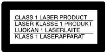
This HD Color Camera is classified as a CLASS 1 LASER PRODUCT.
Laser diode properties
Wave length: 1310±40 nm
Emission duration: Pulse Modulation
Laser output power: 141 μW ^+37_-29
The use of optical instruments with this product will increase eye hazard.
CAUTION
Use of controls or adjustments or performance of procedures other than those specified herein may result in hazardous radiation exposure.
For the customers in Europe
This product with the CE marking complies with both the EMC Directive and the Low Voltage Directive issued by the Commission of the European Community.
Compliance with these directives implies conformity to the following European standards:
• EN60950-1: Product Safety
• EN55103-1: Electromagnetic Interference (Emission)
- EN55103-2: Electromagnetic Susceptibility (Immunity) This product is intended for use in the following Electromagnetic Environments:
E1 (residential), E2 (commercial and light industrial), E3 (urban outdoors), E4 (controlled EMC environment, ex. TV studio)
The manufacturer of this product is Sony Corporation, 1-7-1 Konan, Minato-ku, Tokyo, Japan.
The Authorized Representative for EMC and product safety is Sony Deutschland GmbH, Hedelfinger Strasse 61, 70327 Stuttgart, Germany. For any service or guarantee matters please refer to the addresses given in separate service or guarantee documents.
Phenomena Specific to CCD Image Sensors....66
Locations and Functions of Parts....67
Accessory Attachments....67
Controls and Connectors....68
Preparations....76
Attaching a Lens 76
Adjusting the Flange Focal Length....76
Attaching a Viewfinder....76
Adjusting the Shoulder Pad Position ....78
Mounting the Camera to a Tripod....79
Adjustments and Settings for Recording....80
Adjusting the Black Balance and White Balance ....80
Setting the Electronic Shutter 83
Setting the Camera Outputs ....84
Viewfinder Screen Status Display....87
Menu Operations ....88
Starting Menu Operations....88
Selecting Pages 89
Setting the Menu Items....90
Editing the USER Menu 90
Menu List....94
OPERATION Menu 94
PAINT Menu 99
MAINTENANCE Menu....103
FILE Menu....106
DIAGNOSIS Menu....108
Using a "Memory Stick"....109
Specifications ....111
HDC1500....111
HDC1550 112
HDC1400....114
HDC1450....115
Overview
The HDC1500-series cameras, HDC1500, HDC1550, HDC1400, and HDC1450, are 2/3-type high-definition portable video cameras equipped with CCD for 2,200,000 pixels. They incorporate the latest pickup elements and digital signal-processing LSI to yield higher picture
quality and higher stability in image creation while maintaining conventional popular functions and operability.
The differences among the models are shown below:
| HDC1500 HDC1550 HDC1400 HDC1450 | ||||||||
| JN4/SYL models | CE/E33 models | UC model CE | model JN3/JN4 models | CE/E33 models | UC model CE | model | ||
| Operation panel | SY type | European type | SY type | European type | SY type | European type | SY type | European type |
| Control connector | Fiber Triax Fiber | Triax | ||||||
| Video format coverage | 1080/50i, 1080/59.94i, 1080/23.98P, 1080/24P, 1080/25P, 1080/29.97P, 720/50P, 720/59.94P, 1080/50P, 1080/59.94P | 1080/50i, 1080/59.94i, 1080/23.98P, 1080/24P, 1080/25P, 1080/29.97P, 720/50P, 720/59.94P | 1080/59.94i, 720/59.94P | 1080/50i, 720/50P | 1080/59.94i, 720/59.94P | 1080/50i, 720/50P | ||
| Built-in filters | Optical ND filters (1/4ND, 1/8ND, 1/16ND,1/64ND)Optical CC filters (cross, 3200K, 4300K, 6300K, 8000K)Electric filter (5600K) | Optical ND filters (1/4ND, 1/16ND,1/64ND)Optical cross filterElectric filter (5600K) | ||||||
| HD SDI output | BNC connector×2 (HD SDI with embedded audio ×1, with no embedded audio ×1), Dual Link | BNC connector×1 (No embedded audio) | ← | ← | ||||
| Promptor output | 2 channels 1 channel | ← | ← | |||||
| Genlock/return input | Yes | No | ||||||
Features
High picture quality and high performance
The new 2/3-type Progressive IT CCD for 2,200,000 pixels conforms to driving formats up to 1080/59.94P, achieving high sensitivity and low smear. In addition, the 14-bit A/D converter and a unique signal-processing LSI provide picture quality of optimal grade.
Multiple formats
The HDC1500 covers ten video formats, HDC1550 covers eight video formats, and HDC1400 and HDC1450 covers two video formats. With the HDC1500, signal output of 1080/50P and 59.94P from the camera head is also possible via the Dual Link interface.
Newly designed integrated unit with low center of gravity
The basic design has been reworked. The stylish appearance with low-slung design improves operability as a portable camera and, when used in combination with the HDLA1500-series Large Lens Adaptor, it permits the viewfinder to be mounted at a low position, making the viewfinder position closer to the optical axis of the lens for highly efficient operations.
Swing handle
The swinging structure of the handle enables the large viewfinder mounted on the HDLA1500-series Large Lens Adaptor to be shifted forward, giving it the same total longitudinal size as a standard studio-use camera, for operability equivalent to that of a standard studio-use camera.
Position-adjustable shoulder pad
The position of the shoulder pad can be adjusted for stable shooting according to the build of the camera operator, the type of lens in use, or the shooting style.
A low-repulsion shoulder pad (position fixed) is avaliable as an option (Part No.: A-8286-346-A).
Function-assignable switches
The camera has a switch to which various functions can be assigned on the side panel. You can activate your desired function, such as electronic color-temperature conversion, instantly when shooting by assigning it to the switch in advance. Switches on the handle are also available as function assignable switches.
Memory Stick ^1) operation
The camera is equipped with a Memory Stick port, which enables setup data storage and software upgrading using Memory Sticks.
1) Memory Stick and are trademarks of Sony Corporation.
Various color-reproduction functions
Selection of the gamma table
Multiple gamma tables are provided, enabling you to use multiple formats and perform flexible image creation.
Multimatrix color correction
In addition the standard 6-axis matrix function, the camera has a multimatrix function that permits you to adjust the hue and chroma for color components in 16-axis directions independently. This is quite useful in color matching among multiple cameras.
Knee saturation
Change of hue and decrease in chroma that occur in highlighted areas can be compensated.
This enables reproduction of natural skin tones under strong lighting.
Low key saturation
Hue and saturation in low-key zones can be compensated. Thus, compensation for color reproduction in all zones is enabled in combination with matrix color compensation and knee saturation functions.
Versatile detail control functions
Skin-tone detail function
This function allows control (emphasis or suppression) of the detail level for just a certain hue or chroma area in the image, by creating a detail gate signal from color components of your specified hue, such as skin tones. The detail levels of three hues can be adjusted independently at the same time.
Detail boost-frequency control
The boost frequency can be adjusted from 20 to 30 MHz. This allows the detail thickness to be set appropriately for the subject, thus enabling more subtle image expression.
H/V ratio control
The ratio between horizontal and vertical detail can be adjusted.
White/black limiter
The white and black details can be limited independently.
Easy menu-based setting
Selections and settings for viewfinder display items, safety-zone marker ^2) or center marker, ^3) screen size marker, etc. can be made quickly and easily, using setup menus displayed on the viewfinder screen or an external monitor.
2) Safety zone marker:
A box-shaped marker displayed on the viewfinder screen which indicates 80%, 90%, 92.5%, or 95% of the total screen area
3) Center marker:
A cross-shaped marker which indicates the center of the viewfinder screen
Wide variety of viewfinder display options
Along with items such as operation messages, a zebra pattern, ^4) a safety-zone marker, and a center marker, camera settings may also be displayed on the viewfinder screen. Furthermore, there are other indicators arranged above and below the viewfinder, such as a tally lamp, battery warning indicator, and an indicator to tell you that one or more settings are other than standard. This makes it simple to check the status of the camera.
4) Zebra pattern:
A stripe pattern displayed on the viewfinder screen which indicates the portions where the video level is above about 70% or 100%. Used to check the video level of the subject.
Optical digital transmission (HDC1500/1400)
The camera uses electro-optical coding cable for 1.5-gigabit digital optical transmission between the camera and a Camera Control Unit.
High-resolution 2-type monochrome and 3.5-type color multiformat viewfinders (optional)
The HDVF-20A, a multiformat 2-type monochrome CRT viewfinder, and the HDVF-C35W, a multiformat 3.5-type color LCD viewfinder, are available as options to cover various applications.
Prevention of electrical shock
When the power connection is unsafe, the power supply from the connected Camera Control Unit will be shut off.
System Configuration
Peripherals and related devices for the HDC1500-series cameras are shown in the figures on the subsequent pages.
Note
Production of some of the peripherals and related devices shown in the figures has been discontinued. For device about choosing devices, please contact your Sony dealer or a Sony sales representative.
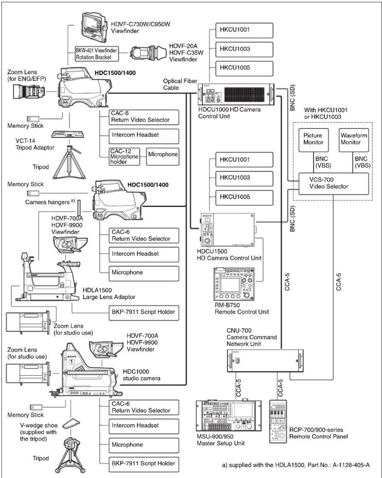
flowchart
graph TD
    A["HDUF-C730W/C950W Viewfinder"] --> B["BKW-401 Viewfinder Rotation Bracket"]
    B --> C["HDUF-20A HDVF-C35W Viewfinder"]
    D["Zoom Lens (for ENG/EFP)"] --> E["HDC1500/1400"]
    E --> F["CAC-6 Return Video Selector"]
    E --> G["Intercom Headset"]
    E --> H["CAC-12 Microphone holder"]
    E --> I["Microphone"]
    J["Memory Stick"] --> K["VCT-14 Tripod Adaptor"]
    K --> L["Tripod"]
    M["Memory Stick"] --> N["Camera hangers a)"]
    N --> O["HDUF-700A HDVF-9900 Viewfinder"]
    O --> P["CAC-6 Return Video Selector"]
    O --> Q["Intercom Headset"]
    O --> R["Microphone"]
    S["HDLA1500 Large Lens Adaptor"] --> T["Zoom Lens (for studio use)"]
    T --> U["BKP-7911 Script Holder"]
    V["HDUF-700A HDVF-9900 Viewfinder"] --> W["Zoom Lens (for studio use)"]
    X["HDUF-700A HDVF-9900 Viewfinder"] --> Y["HDC1000 studio camera"]
    Z["Memory Stick"] --> AA["V-wedge shoe (supplied with the tripod)"]
    AB["Tripod"] --> AC["HCUCU1001 or HKCU1003"]
    AD["With HKCU1001 or HKCU1003"] --> AE["Picture Monitor"]
    AD --> AF["VCS-700 Video Selector"]
    AG["With HKCU1001 or HKCU1003"] --> AH["Picture Monitor"]
    AG --> AI["VCS-700 Video Selector"]
    AJ["With HKCU1001 or HKCU1003"] --> AK["Picture Monitor"]
    AJ --> AL["VCS-700 Video Selector"]
    AM["With HKCU1001 or HKCU1003"] --> AN["Picture Monitor"]
    AM --> AO["VCS-700 Video Selector"]
    AP["With HKCU1001 or HKCU1003"] --> AQ["Picture Monitor"]
    AP --> AR["VCS-700 Video Selector"]
    AS["With HKCU1001 or HKCU1003"] --> AT["Picture Monitor"]
    AS --> AU["VCS-700 Video Selector"]
    AV["With HKCU1001 or HKCU1003"] --> AW["Picture Monitor"]
    AV --> AX["VCS-700 Video Selector"]
    AY["With HKCU1001 or HKCU1003"] --> AZ["Picture Monitor"]
    AY --> BA["VCS-700 Video Selector"]
    BB["With HKCU1001 or HKCU1003"] --> BC["Picture Monitor"]
    BB --> BD["VCS-700 Video Selector"]
    BE["With HKCU1001 or HKCU1003"] --> BEP["BNC (VBS)"]
    BE --> BF["BNC (VBS)"]
    BG["With HKCU1001 or HKCU1003"] --> BH["BNC (SD)"]
    BI["With HKCU1001 or HKCU1003"] --> BJ["BNC (SD)"]
    BK["With HKCU1001 or HKCU1003"] --> BL["BNC (SD)"]
    BM["With HKCU1001 or HKCU1003"] --> BN["BNC (SD)"]
    BO["With HKCU1001 or HKCU1003"] --> BP["BNC (SD)"]
    BQ["With HKCU1001 or HKCU1003"] --> BQB["BNC (VBS)"]
    CA["With HKCU1001 or HKCU1003"] --> CB["BNC (VBS)"]
    CA --> CC["BNC (SD)"]
    CE["With HKCU1001 or HKCU1003"] --> CF["BNC (SD)"]
    CG["With HKCU1001 or HKCU1003"] --> CH["BNC (SD)"]
    CI["With HKCU1001 or HKCU1003"] --> CJ["BNC (SD)"]
    CK["With HKCU1001 or HKCU1003"] --> CL["BNC (SD)"]
    CM["With HKCU1001 or HKCU1003"] --> CN["BNC (SD)"]
    CO["With HKCU1001 or HKCU1003"] --> CP["BNC (SD)"]
    CQ["With HKCU1001 or HKCU1003"] --> CR["BNC (SD)"]
    CS["With HKCU1001 or HKCU1003"] --> CSB["BNC (SD)"]
    CT["With HKCU1001 or HKCU1003"] --> CU["BNC (SD)"]
    CV["With HKCU1001 or HKCU1003"] --> CW["BNC (SD)"]
    CX["With HKCU1001 or HKCU1003"] --> CYB["BNC (SD)"]
    CZ["With HKCU1001 or HKCU1003"] --> DA["BNC (SD)"]
    DB["With HKCU1001 or HKCU1003"] --> DC["BNC (SD)"]
    DD["With HKCU1001 or HKCU1003"] --> DE["BNC (SD)"]
    DF["With HKCU1001 or HKCU1003"] --> DFb["BNC (VBS)"]
    DF --> DG["BNC (VBS)"]
Connection example 2 (HDC1550/1450)
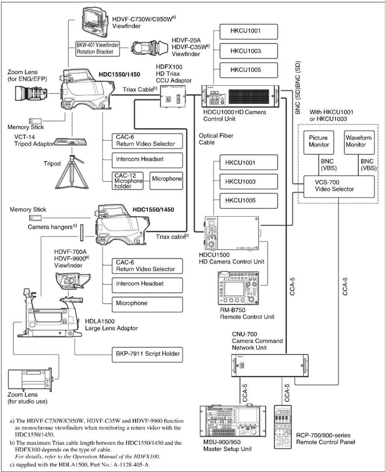
flowchart
graph TD
    A["Zoom Lens (for ENG/EFP)"] --> B["HDC1550/1450"]
    B --> C["Triax Cable"]
    C --> D["HDFX100 HD Triax CCU Adaptor"]
    D --> E["HDCU1000 HD Camera Control Unit"]
    E --> F["BNC (SD)BNC (SD)"]
    F --> G["With HKCU1001 or HKCU1003"]
    G --> H["Picture Monitor"]
    G --> I["VCS-700 Video Selector"]
    H --> J["BNC (VBS)"]
    I --> K["BNC (VBS)"]
    L["Memory Stick"] --> M["HDC1550/1450"]
    M --> N["CAC-6 Return Video Selector"]
    M --> O["Intercom Headset"]
    M --> P["CAC-12 Microphone holder"]
    M --> Q["Microphone"]
    M --> R["Triax cable"]
    R --> S["HDCU1500 HD Camera Control Unit"]
    S --> T["RM-B750 Remote Control Unit"]
    T --> U["CNU-700 Camera Command Network Unit"]
    U --> V["MSU-900/950 Master Setup Unit"]
    V --> W["RCP-700/900-series Remote Control Panel"]
    X["HDVF-C730W/C950W, HDVF-C35W and HDVF-9900 function as monochrome viewfinders when monitoring a return video with the HDC1550/1450."] --> Y["Zoom Lens (for studio use)"]
    Z["Maximal Triax cable length between the HDC1550/1450 and the HDFX100 depends on the type of cable. For details, refer to the Operation Manual of the HDFX100. c) supplied with the HDLA1500, Part No.: A-1128-405-A"] --> AA["HDVF-700A HDVF-9900a Viewfinder"]
    AB["Camera hangersc"] --> AC["HDLA1500 Large Lens Adaptor"]
    AC --> AD["BKP-7911 Script Holder"]
Connection example 3
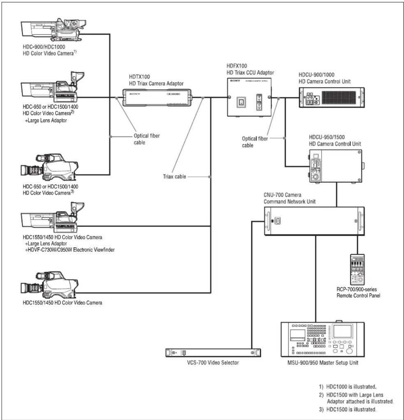
flowchart
graph TD
    A["HDC-900/HDC1000 HD Color Video Camera¹"] --> B["HDTX100 HD Triax Camera Adaptor"]
    C["HDC-950 or HDC1500/1400 HD Color Video Camera²"] --> B
    D["HDC-950 or HDC1500/1400 HD Color Video Camera³"] --> E["Triax cable"]
    F["HDC1550/1450 HD Color Video Camera"] --> G["+Large Lens Adaptor +HDVF-C730W/C950W Electronic Viewfinder"]
    H["HDC1550/1450 HD Color Video Camera"] --> I["VCS-700 Video Selector"]
    B --> J["HDFX100 HD Triax CCU Adaptor"]
    E --> J
    I --> K["MSU-900/950 Master Setup Unit"]
    J --> L["CNU-700 Camera Command Network Unit"]
    L --> M["RCP-700/900-series Remote Control Panel"]
    M --> N["MSU-900/950 Master Setup Unit"]
    style A fill:#f9f,stroke:#333
    style C fill:#f9f,stroke:#333
    style D fill:#f9f,stroke:#333
    style F fill:#f9f,stroke:#333
    style H fill:#f9f,stroke:#333
    style B fill:#ccf,stroke:#333
    style J fill:#ccf,stroke:#333
    style K fill:#ccf,stroke:#333
    style L fill:#cfc,stroke:#333
    style M fill:#cfc,stroke:#333
    style N fill:#fcc,stroke:#333
Maximum cable run with Triax cable
The maximum Triax cable length between the HDC1550/1450 and the HDFX100 or between the HDFX100 and the HDTX100 depends on the type of cable.
For details, refer to the Operation Manual of the HDFX100/HDTX100.
Notes
- The viewfinders function as monochrome viewfinders when monitoring a return video using the HDFX100 and the HDTX100.
• The skin gate signal is superimposed on the camera video signal. When tally becomes ON, the skin gate signal is forced to OFF.
Precautions
Note on laser beams
Laser beams may damage the CCDs. If you shoot a scene that includes a laser beam, be careful not to let a laser beam become directed into the lens of the camera.
Do not subject to severe shocks
Damage to the case or internal components may result.
When finished using
Set the power switch to OFF.
Operation and storage environment
Store in a level place with air conditioning.
If the unit gets wet, make sure it is completely dry before storage.
Avoid use or storage in the following places:
• Extremely hot or cold places
- Places with high humidity
- Places with strong vibration
• Near strong magnetic fields
- In places where it receives much direct sunlight, or near heating equipment
Condensation
If you move the camera from a very cold place to a warm place, or use it in a damp location, condensation may form on the lens or inside the camera.
The camera has no built-in condensation indicator. If you find condensation on the body or lens, switch the camera off and wait for the condensation to disappear for about one hour.
Phenomena Specific to CCD Image Sensors
The following phenomena that may appear in images are specific to CCD (Charge Coupled Device) image sensors. They do not indicate malfunctions.
White flecks
Although the CCD image sensors are produced with high-precision technologies, fine white flecks may be generated on the screen in rare cases, caused by cosmic rays.
This is related to the principle of CCD image sensors and is not a malfunction.
The white flecks especially tend to be seen
- when operating at a high environmental temperature
- when you have raised the master gain (sensitivity)
This product has a compensation function and the problem may be alleviated by automatic black balance adjustment (see page 80).
Smear
When an extremely bright object, such as a strong spotlight or flashlight, is being shot, vertical tails may be produced on the screen, or the image may be distorted.
Aliasing
When fine patterns, stripes, or lines are shot, they may appear jagged or flicker.
Locations and Functions of Parts
Accessory Attachments
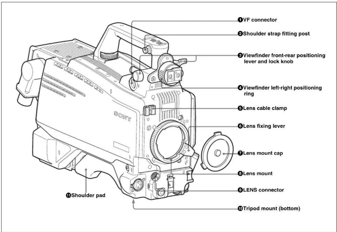
①VF (viewfinder) connector (20-pin)
Connect the cable of the viewfinder (not supplied).
②Shoulder strap fitting post
Attach one end of a shoulder strap (not supplied) to this fitting post, and the other end to the fitting post on the other side of the camera.
③ Viewfinder front-rear positioning lever and LOCK knob
Loosen the lever and knob to adjust the viewfinder position towards the front or rear.
④ Viewfinder left-right positioning ring
Loosen this ring to adjust the viewfinder position towards the left or right.
For details on adjusting the viewfinder position, see "Attaching a Viewfinder" on page 76.
⑤ Lens cable clamp
Used to secure the cable of the lens (not supplied).
⑥ Lens fixing lever
Used to secure the lens in the lens mount.
⑦ Lens mount cap
Cover the lens mount with this cap when a lens is not attached. The cover may be removed by moving the lens fixing lever upwards.
⑧ Lens mount
Used to attach a lens (not supplied).
⑨LENS connector (12-pin)
Connect the lens cable. The camera can control the lens functions through this cable.
⑩Tripod mount
Attach the VCT-14 Tripod Adaptor when mounting the camera on a tripod.
⑪Shoulder pad
You can adjust the position so that you can get the best balance for shooting with the camera on your shoulder.
For details, see "Adjusting the Shoulder Pad Position" on page 78.
Controls and Connectors
Front right
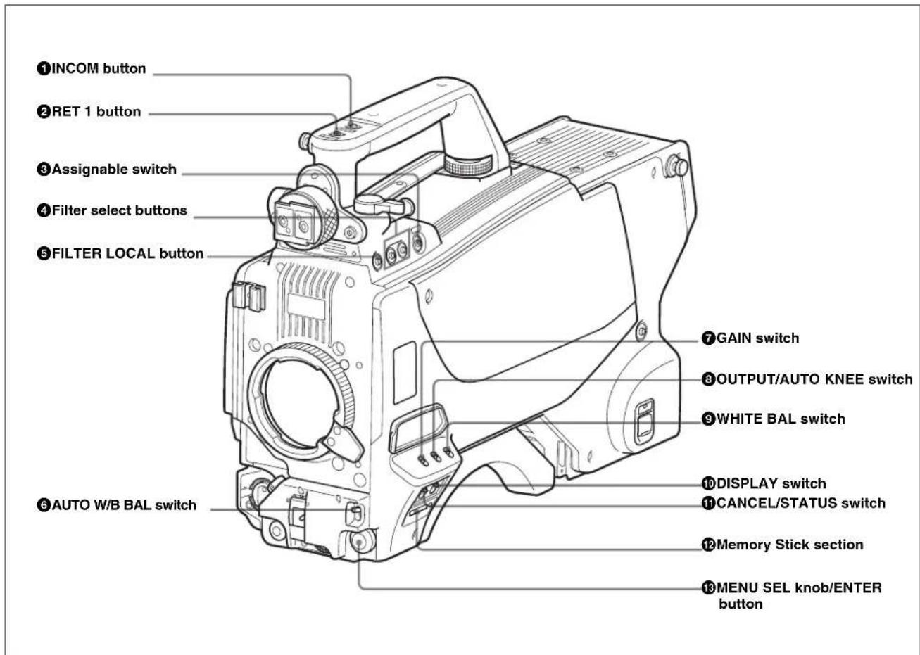
①INCOM (intercom 1) button
The intercom 1 microphone is turned ON while this button is pressed.
You can also assign other functions to this button, using the menu displayed on the viewfinder screen.
②RET 1 (return video 1) button
The return video 1 signal from the camera control unit is monitored on the viewfinder screen while this button is pressed. It function the same as the RET 1 button on the side (page 70) and that on the operation panel on the rear of the camera (page 72 or 73).
You can also assign other functions to this button, using the menu displayed on the viewfinder screen.
③ Assignable switch
You can assign a function using the menu displayed on the viewfinder screen.
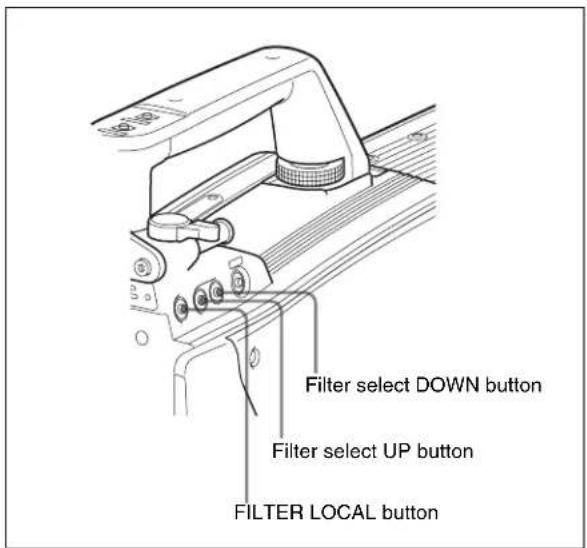
④Filter select buttons
HDC1500/1550
You can switch the built-in ND and CC (color temperature conversion) filters by pressing the selectors while holding the FILTER LOCAL button depressed.
Pressing the left button selects the available ND filters (clear, 1/4ND, 1/8ND, 1/16ND, 1/64ND) in sequence. Pressing the right button selects the available CC filters (cross, 3200K, 4300K, 6300K, 8000K) in sequence.
HDC1400/1450
You can switch the built-in optical filters (clear, 1/4ND, 1/16ND, 1/64ND, cross) by pressing either of these buttons while holding the FILTER LOCAL button depressed.
While holding this button depressed, press either of the filter select buttons to select the built-in optical filters.
⑥ AUTO W/B BAL (white and black balance automatic adjustment) switch
Used to automatically adjust white and black balance when the camera is used in stand-alone status without connecting to the camera control unit.
WHT: Automatically adjust white balance.
BLK: Automatically adjust black balance.
⑦GAIN switch
Used to select the gain of the video amplifier based on lighting conditions when the camera is used in stand-alone status without connecting a camera control unit.
When shipped from the factory, the values set are L = 0 dB, M = 6 dB, and H = 12 dB.
⑧ OUTPUT (output signal selection)/AUTO KNEE switch
Used to select the signal (color bar signal or camera's video signal) to be used as output to a VTR, the viewfinder or a video monitor when the camera is used in stand-alone status without connecting a camera control unit.
When the camera's video signal is being used as output, the auto knee function may be used.
The relationship between the switch setting and the output signal and auto knee function is shown in the table below.
| OUTPUT | AUTO KNEE Function |
| BARS OFF | Output is a color bar signal. |
| CAM OFF | Output is the camera's video signal. The auto knee circuit is disabled. |
| CAM ON | Output is the camera's video signal. The auto knee circuit is enabled. |
⑨WHITE BAL (white balance memory selection) switch
Used to select the white balance adjustment method or the memory used to store the adjusted value when the camera is used in stand-alone status without connecting a camera control unit.
PRST (preset): White balance is adjusted to a preset value corresponding to a color temperature of 3200K.
A or B: Selects memory A or B.
⑩DISPLAY switch
The functions of the DISPLAY switch are as follows:
ON: Characters and messages showing the camera settings and operating status may be displayed on the viewfinder screen.
OFF: Status messages will not appear on the viewfinder screen.
MENU: Menus for camera settings will be displayed on the viewfinder screen.
⑪ CANCEL/STATUS switch
When a menu is displayed on the viewfinder screen, you can cancel any changed settings or return the display to the previous menu.
When no menu is displayed on the viewfinder screen, the status information of this camera is displayed.
⑫Memory Stick section
A slot to accommodate a “Memory Stick” and an access lamp are provided behind the panel. The access lamp lights in red while writing or reading data to/from a “Memory Stick.”
Note
When the access lamp is lit, do not insert/remove the "Memory Stick" or turn off the camera.
13 MENU SEL (menu select) knob/ENTER button (rotary encoder)
Used to select settings from menus displayed on the viewfinder screen (by rotating the knob) and to confirm settings (by pushing the button).
Note
When a camera control unit or a remote control device, such as MSU-900/950 and the RCP-700/900-series Remote Control Panel, is connected, the functions of ⑥ to
⑨ are controlled from the external control device and the controls on the camera are disabled.
Front left
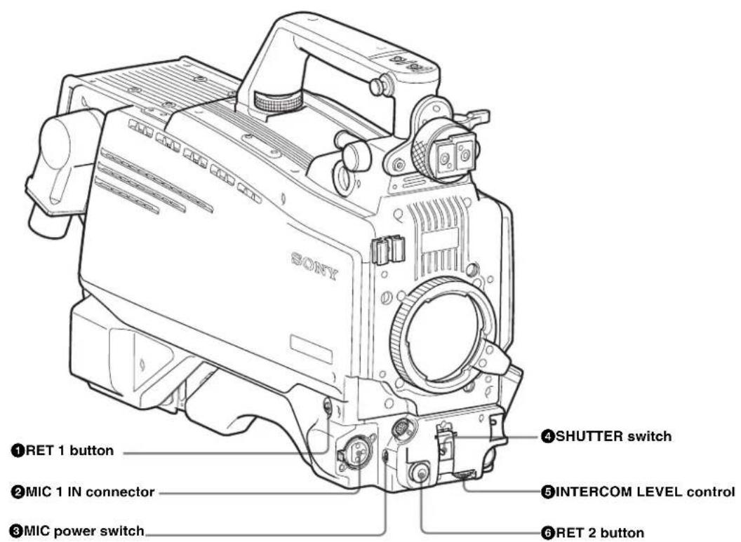
①RET 1 (return video 1) button
The return video 1 signal from the camera control unit is monitored on the viewfinder screen while this button is pressed. It function the same as the RET1 buttons on the handle (page 68) and that on the operation panel on the rear of the camera (page 72 or 73).
You can also assign other functions to this button, using the menu displayed on the viewfinder screen.
②MIC 1 IN (microphone 1 input) connector (XLR 3-pin)
Connect a microphone.
This connector and the AUDIO IN CH-1 connector (page 75) on the operation panel on the rear of the camera are alternately activated with the CH1 input select switch (page 75).
③MIC (microphone) power switch
+48V: To supply a power of +48 V to the connected microphone.
OFF: Not to supply a power to the connected microphone.
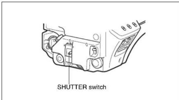
④SHUTTER switch
Used for setting the electronic shutter functions when the camera is used in stand-alone status without connecting a camera control unit.
OFF: The electronic shutter does not function.
ON: The electronic shutter is activated.
SEL: The shutter speed and shutter mode change each time the switch is set to this position.
For details, see "Setting the Electronic Shutter" on page 83.
⑤ INTERCOM LEVEL control
To adjust the intercom/earphone volume level. The intercom level adjustment is enabled when the INTERCOM 1 and 2 LEVEL/MIC switches (on the SY-type operation panel, page 72) or the LEVEL switch (on the European-type operation panel, page 73) on the rear of the camera are set to “FRONT.”
⑥RET 2 (return video 2) button
When this button is pressed, the picture on the viewfinder changes to the return video signal selected with the RET 2 select switch (page 72 or 73) on the operation panel on the rear of the camera.
You can also assign other functions to this button, using the menu displayed on the viewfinder screen.
Rear
The figure shows HDC1500.
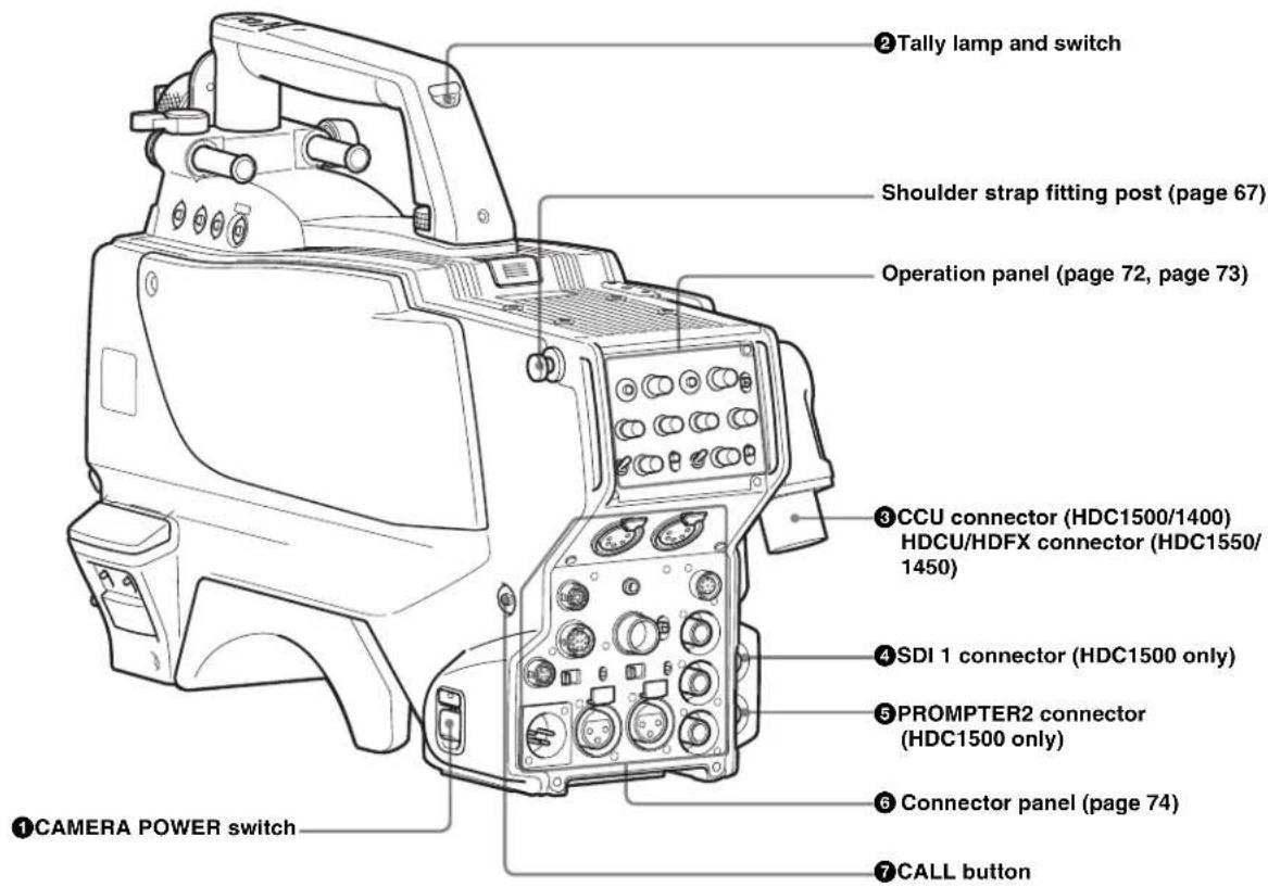
①CAMERA POWER switch
CCU: Power supply will be received from the camera control unit.
EXT: Power supply will be received through the DC IN connector.
②Tally lamp and switch
ON: The tally lamp lights upon a tally signal input to the connected camera control unit or a call signal generated by pressing a CALL button.
OFF: The tally lamp is prevented from lighting.
③CCU (Camera Control Unit) connector (optical/electrical multi-connector) (HDC1500/1400)
Connect a camera control unit using an optical electrocomposite cable.
③HDCU/HDFX (HD Triax CCU) connector (Triax connector) (HDC1550/1450)
Connect the HDFX100 HD Triax CCU Adaptor using a Triax cable. A camera control unit can be connected via the HDFX100.
④ SDI 1 (serial digital interface 1) connector (BNC type) (HDC1500 only)
Used for HD SDI signal output.
⑤PROMPTER2 connector (BNC type) (HDC1500 only)
Used for prompter 2 signal output.
This operates only when a camera control unit having a prompter 2 input is connected.
⑥ CALL button
When you press this button, the red tally lamp of the RCP-700/900-series Remote Control Panel or the MSU-900/950 Master Setup Unit, will light. Use to call the operator of the RCP or MSU.
Operation panel
SY type: For UC/SYL/JN3 (USA, Canada, and other countries) and JN4 (East Asia) models (for NTSC areas)
For details on the differences among models, see "Overview" on page 60.
① INTERCOM1 and INTERCOM2 controls and switches
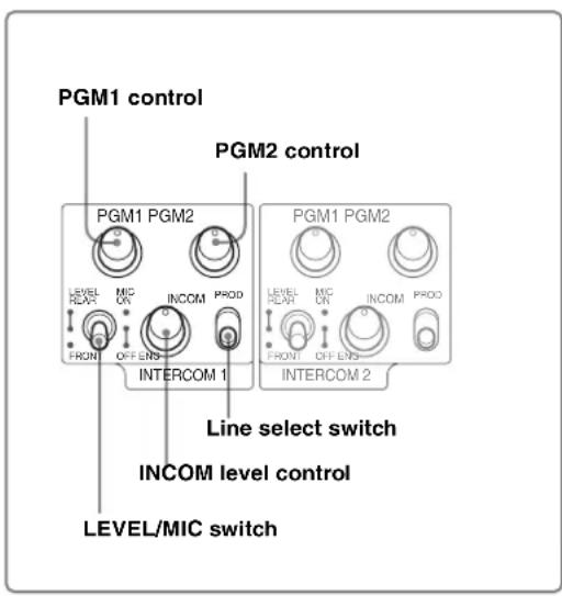
② RET 1 button and select switch
① INTERCOM1 and INTERCOM2 controls and switches
There are PGM1 and 2 controls incorporated with a line select switch, a LEVEL/MIC switch, and INCOM level control each for intercom line 1 and 2.
PGM1 (program 1) control
Adjust the audio reception level of program 1.
PGM2 (program 2) control
Adjust the audio reception level of program 2.
LEVEL/MIC switch
REAR/ON: The intercom headset microphone is turned on. The intercom audio reception level is adjusted with the INCOM level control.
REAR/OFF: The intercom headset microphone is turned off. The intercom audio reception level is adjusted with the INCOM level control.
FRONT/OFF: The intercom headset microphone is turned off. The intercom audio reception level is adjusted with the INTERCOM LEVEL control on the front of the camera.
INCOM level control
Adjust the intercom audio reception level.
Line select switch
Select the intercom line.
PROD: Producer line
ENG: Engineer line
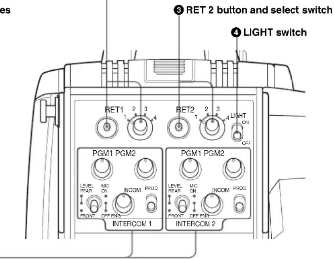
②RET 1 (return video 1) button and select switch
The return video signal selected with the switch is displayed on the viewfinder screen while the button is pressed.
③RET 2 (return video 2) button and select switch
When other return video systems are used in addition to return video 1, you can monitor the signal selected with the switch on the viewfinder screen while pressing the button.
Note
The RET 1 button has priority over the RET 2 button if both buttons are pressed.
4 LIGHT switch
Set to ON to illuminate the operation panel.
European type: For CE (Europe) and E33 (China and South Asia) models (for PAL areas)
For details on the differences among models, see "Overview" on page 60.
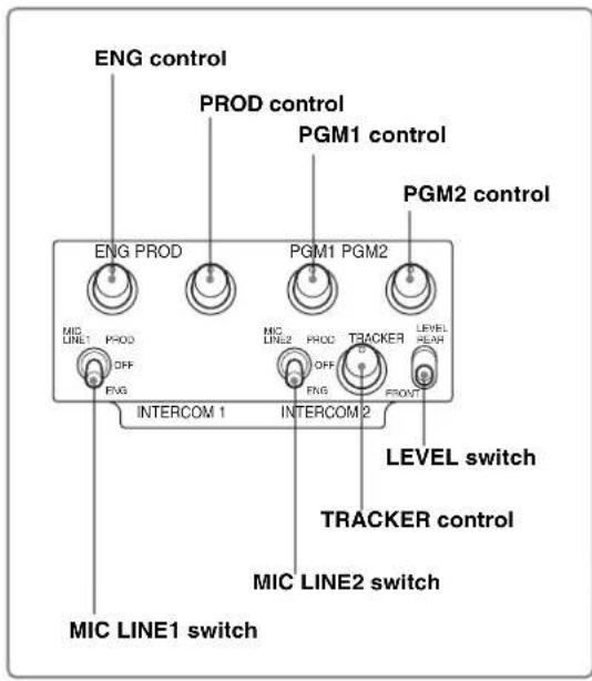
①INTERCOM1 and INTERCOM2 controls and switches
① INTERCOM1 and INTERCOM2 controls and switches
The reception level controls are common to intercom 1 and intercom 2. The talk lines can be set independently for intercom 1 and intercom 2.
ENG (engineer line) control:
Adjust the intercom audio reception level of the engineer line.
PROD (producer line) control
Adjust the intercom audio reception level of the producer line.
PGM1 (program 1) control
Adjust the audio reception level of program 1.
PGM2 (program 2) control
Adjust the audio reception level of program 2.
TRACKER control
Adjust the intercom audio reception level at the TRACKER connector (page 74) on the connector panel when using the connector for intercom.
MIC LINE1 (intercom microphone line 1) switch
Select the talk line for intercom 1.
PROD: To talk over the producer line
OFF: To turn off the headset microphone for intercom line 1.
ENG: To talk over the engineer line
MIC LINE2 (intercom microphone line 2) switch
Select the talk line for intercom 2.
PROD: To talk over the producer line
OFF: To turn off the headset microphone for intercom line 2.
ENG: To talk over the engineer line
LEVEL switch
REAR: The intercom audio reception level is adjusted with the controls on this panel.
FRONT: The intercom audio reception level is adjusted with the INTERCOM LEVEL control on the front of the camera.
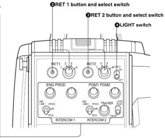
②RET 1 (return video 1) button and select switch
The return video signal selected with the switch is displayed on the viewfinder screen while the button is pressed.
③RET 2 (return video 2) button and select switch
When other return video systems are used in addition to return video 1, you can monitor the signal selected with the switch on the viewfinder screen while pressing the button.
Note
The RET 1 button has priority over the RET 2 button if both buttons are pressed.
④LIGHT switch
Set to ON to illuminate the operation panel.
Connector panel
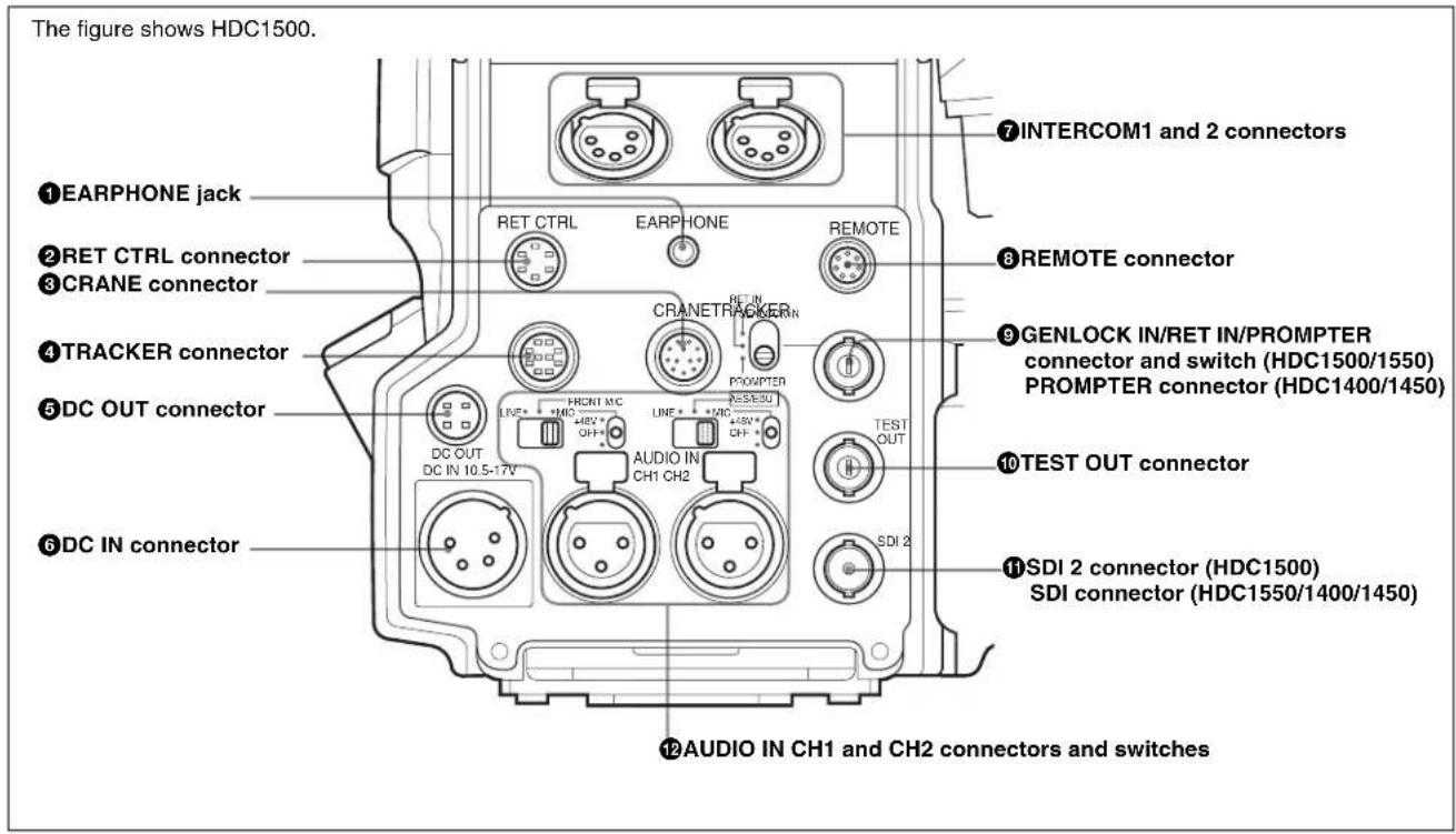
①EARPHONE jack (stereo minijack)
Connect an earphone or headset for output of the intercom.
②RET CTRL (return control) connector (6-pin)
Used for connection to a CAC-6 Return Video Selector.
③CRANE connector (12-pin)
For external interface, such as viewfinder (and external data with HDC1500/1400).
④TRACKER connector (10-pin)
For external interface, such as intercom and tally.
⑤DC OUT (DC power supply output) connector (4-pin)
Used to supply power to devices such as a wireless receiver (optional).
⑥DC IN (DC power supply input) connector (XLR 4-pin)
Used for connection to the AC-DN10 AC Adaptor to supply power to the camera.
⑦ INTERCOM1 and 2 (intercom 1 and 2) connectors (XLR 5-pin)
Used for input and output of intercom audio signals if an XLR 5-pin headset is connected.
The INTERCOM 1 connector can be used for communication over the engineer line even when the power is off, as long as the power LED is lit in red.
⑧ REMOTE connector (8-pin)
Used for connection to an RM-B150/B750 Remote Control Unit, RCP-700/900-series Remote Control Panel, or MSU-900/950 Master Setup Unit.
Note
When the camera is connected to a CCU, do not connect any remote control device, such as RCP and MSU, to this connector.
⑨GENLOCK IN/RET IN/PROMPTER (external gen-lock signal input/return video signal input/prompter signal output) connector (BNC type) and switch (HDC1500/1550)
Set the switch according to the signal at the connector.
GENLOCK IN: Used for input of an external gen-lock signal (VBS or 3-level sync) when the camera is used without a camera control unit connected
RET IN: Used for input of the return video signal when the camera is used without a camera control unit connected.
The connector accepts analog HD signals only. SDI signals are not acceptable. Supply a signal of 1080i (720P is not acceptable).
The signal supplied to this connector cannot be fed as RET OUT from the TEST OUT or SDI OUT connector.
PROMPTER: Used for output of a prompter signal (valid only when a camera control unit is connected). When a camera control unit having two prompter inputs is
connected, the signal of input 1 is output from this connector.
⑨PROMPTER (prompter signal output) connector (BNC type) (HDC1400/1450)
Used for output of a prompter signal (valid only when a camera control unit is connected). When a camera control unit having two prompter inputs is connected, the signal of input 1 is output from this connector.
⑩TEST OUT connector (BNC type)
Used to output the analog signal.
This also supplies the VBS signal, an HD signal nearly equal to the signal output from the VF connector, an HD-SYNC signal, or an SD-SYNC signal depending on which of these you have selected on the menu.
⑪SDI 2 (serial digital interface 2) connector (BNC type) (HDC1500)
Used for HD SDI or SD SDI signal output.
⑪ SDI (serial digital interface) connector (BNC type) (HDC1550/1400/1450)
Used for HD SDI or SD SDI signal output.
Note
No audio signal is embedded to the output from the SDI 2/SDI connector.
12 AUDIO IN CH1 and CH2 connectors (XLR 3-pin) and switches
Connect audio signals. An input select switch and microphone power switch are provided for each channel.
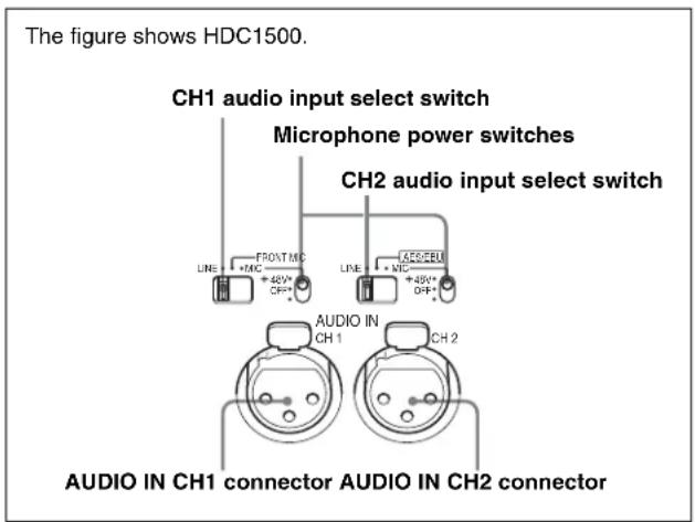
CH1 audio input select switch
Set to the appropriate position according to the equipment connected to the AUDIO IN CH1 connector.
LINE: When a line-level (0 dBu) signal source is connected
FRONT MIC: When using the microphone connected to the MIC 1 IN connector
MIC: When an external microphone is connected
CH2 audio input select switch
Set to the appropriate position according to the equipment connected to the AUDIO IN CH2 connector.
LINE: When a line-level (0 dBu) signal source is connected
AES/EBU (HDC1500/1400 only): When a digital audio signal is connected (The signal must be in synchronization with the camera output). The corresponding position on the HDC1550/1450 is invalid (NC).
MIC: When an external microphone is connected
Microphone power switches
When a microphone is connected to the corresponding AUDIO IN connector, set whether or not to supply a power to the microphone.
+48V: To supply a power of +48 V
OFF: Not to supply a power
(No function has been assigned to the lowermost position.
No power is supplied to the microphone.)
Note
To supply a power of +12 V, modification of the camera is required.
Preparations
Attaching a Lens
The procedure for attaching a lens to the camera is as follows:
For information on handling lenses, refer to the lens' operation manual.
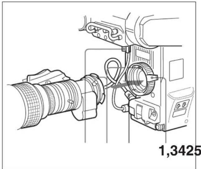
natural_image
Technical line drawing of a camera setup with lens and control panel (no text or symbols)1 Push the lens fixing lever upwards and remove the lens mount cap from the lens mount.
2 Align the lens' alignment pin with the notch in the upper part of the lens mount and insert the lens into the mount.
3 While supporting the lens, push the lens fixing lever downwards to secure the lens.
4 Connect the lens cable to the LENS connector.
5 Secure the lens cable with the cable clamp.
Adjusting the Flange Focal Length
Adjustment of the flange focal length ^1) is necessary in the following situations.
• The first time a lens is attached
- When changing lenses
- When zooming and the focus is not sharp at both telephoto and wide angle
Note
The various parts of the lens used in adjusting the flange focal length are in different positions on different lenses. Refer to the lens' operation manual.
The procedure for adjusting the flange focal length is as follows:
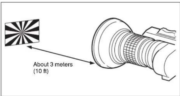
1 Set the iris control to manual, and open the iris fully.
2 Place a flange focal length adjustment chart approximately 3 meters from the camera and adjust the lighting to get an appropriate video output level.
3 Loosen the Ff ^2) ring lock screw.
4 With either manual or power zoom, set the zoom ring to telephoto.
5 Aim at the flange focal length adjustment chart and turn the focus ring to focus the image.
6 Set the zoom ring to wide angle.
7 Turn the Ff ring to bring the chart in focus. Take care not to move the distance ring.
8 Repeat steps 4 through 7 until the image is focus at both telephoto and wide angle.
9 Tighten the Ff ring lock screw.
1) Flange focal length: The distance between the lens mount attachment plane and the imaging plane
2) Fl: Abbreviation of flange focal length
Attaching a Viewfinder
Caution
When the viewfinder is attached, do not leave the camera (or the camcorder) with the eyepiece facing the sun. Direct sunlight can enter through the eyepiece, be focused in the viewfinder and cause fire.
Example: Attaching a HDVF-20A/C35W Viewfinder
For details on the viewfinder, refer to the instruction manual of the viewfinder.
Attaching procedure
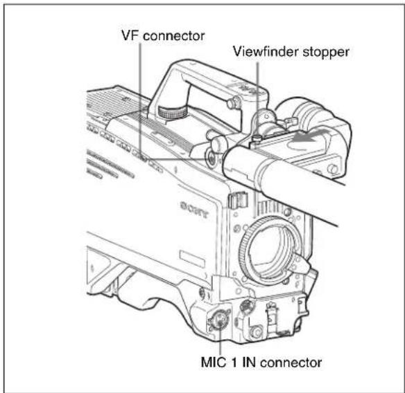
1 Slide the viewfinder in the direction of the arrow. The viewfinder stopper automatically pops down.
2 Loosen the viewfinder left-right positioning ring, slide the viewfinder side to side to the most convenient position and tighten the ring.
3 Connect the viewfinder cable to the VF connector of the camera.
4 Connect the microphone cable to the MIC 1 IN connector of the camera.
Adjusting the viewfinder position
The viewfinder position may be adjusted towards the front and rear and to the left and right to make it easy to see into it.
To adjust the position to the left or right
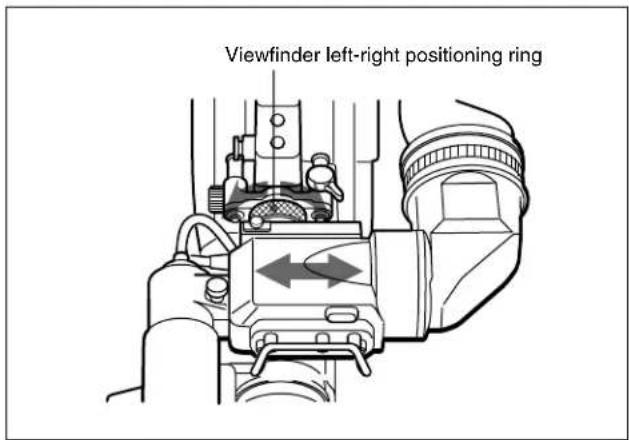
1 Loosen the viewfinder left-right positioning ring.
2 Slide the viewfinder left or right to move it into a good viewing position.
3 Tighten the viewfinder left-right positioning ring.
To adjust the position forward or backward
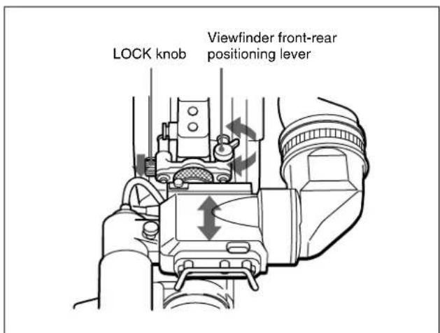
1 Loosen the viewfinder front-rear positioning lever and LOCK knob.
2 Slide the viewfinder towards the front or rear of the camera to move it into a good viewing position.
3 Tighten the viewfinder front-rear positioning lever and LOCK knob.
To detach the viewfinder
Loosen the viewfinder left-right positioning ring, pull the viewfinder stopper, then pull out the viewfinder by sliding it in the direction opposite to that when attached.
Keeping the viewfinder from hitting your leg
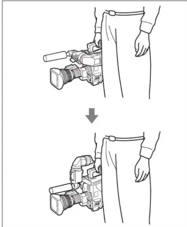
To keep the viewfinder from bumping your leg when carrying the camera, install the BKW-401 Viewfinder Rotation Bracket (optional) and rotate the viewfinder upwards.
natural_image
Line drawing showing a person adjusting a digital camera module, with no text or symbols present.Note
Lock the viewfinder in a slightly forward position before rotating it upwards. If the viewfinder is in its rearmost position, the arm of the viewfinder rotation bracket will strike the grip.
Attaching procedure of the BKW-401
1 Turn the arm of the rotation mechanism assembly of the BKW-401 in the direction of the arrow in the following illustration.
Next, using a hexagonal wrench 3 mm across flats, remove the bolts (M4 × 8) together with the washers, to separate the rotation mechanism assembly from the viewfinder front-back positioning mechanism assembly.
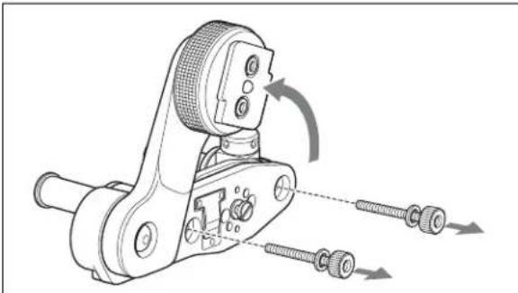
natural_image
Technical line drawing of a mechanical clamp or crimping tool with threaded fasteners and directional arrows indicating movement (no text or symbols present)2 In the same manner as step 1, remove the viewfinder shoe of the camera from the front-rear positioning mechanism.
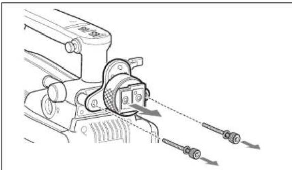
natural_image
Technical line drawing of a mechanical clamp or bracket assembly with two screws inserted (no text or symbols)3 Using the two bolts (M4 × 8) and the washers removed from the camera in step 2, attach the rotation mechanism assembly of the BKW-401 to the camera.
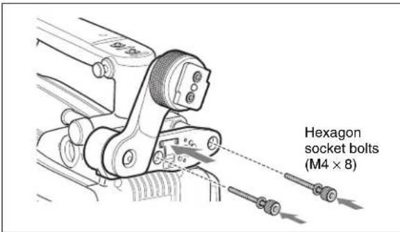
Adjusting the Shoulder Pad Position
You can shift the shoulder pad from its center position (factory setting) backward by up to 10 mm (3/8 inch) or forward by up to 25 mm (1 inch). This adjustment helps you get the best balance for shooting with the camcorder on your shoulder.
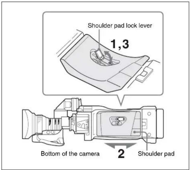
Adjusting procedure
1 Raise the lever in the center of the shoulder pad to unlock the shoulder pad.
2 Slide the shoulder pad backward or forward until it is in the most convenient position.
3 Bring down the lever to lock the shoulder pad in the selected position.
Mounting the Camera to a Tripod
Mount the camera to a tripod using a VCT-14 Tripod Adaptor.
Caution
- Select an appropriate hole from among those at the bottom of the tripod adaptor considering the balance of the weight of the camera and the tripod adaptor. If an inappropriate hole is selected, the camera may fall over.
- Check that the size of the selected hole matches that of the screw of the tripod. If they do not match, the tripod adaptor cannot be attached to the tripod securely.
Mounting procedure
1 Attach the tripod adaptor to the tripod and secure it with the screw.
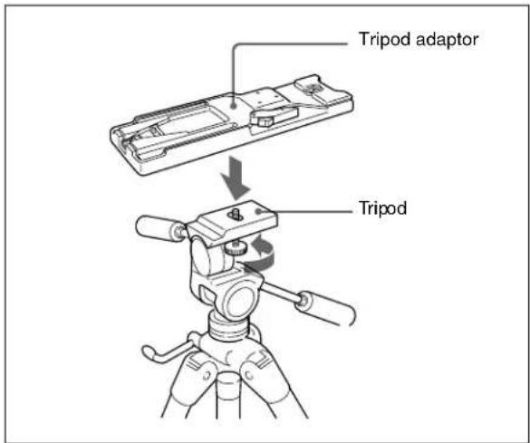
2 Place the camera on the tripod adaptor, and slide forward it along the groove of the tripod adaptor until it clicks.
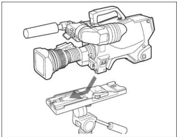
natural_image
Technical line drawing of a video camera and its internal clamp device (no text or symbols)To remove the camera from the tripod adaptor
Hold down the red button and pull the lever in the direction of the arrow.
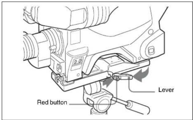
If the pin of the tripod adaptor does not return to its original position
After removing the camera, if the pin of the tripod adaptor does not return to its original position, hold down the red button and move the lever in the direction of the arrow to return the pin to its original position. It is not possible to mount a camera with the pin not seated.
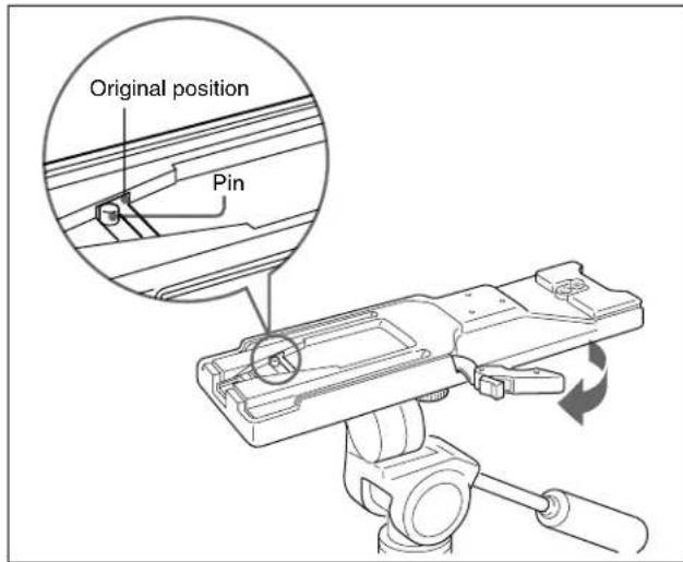
Adjustments and Settings for Recording
Adjusting the Black Balance and White Balance
In order to maintain high picture quality when using the camera, it is necessary to set the black balance and white balance appropriately for the conditions.
Note
When a camera control unit or a remote control device, such as MSU-900/950 and the RCP-700/900-series Remote Control Panel, is connected, the black balance and white balance are controlled from the external control device and controls on the camera are disabled.
Black balance adjustment
The black balance needs adjustment in situations like the following:
• The first time the camera is used
- When the camera is used after a long period of disuse
- When the surrounding temperature changes greatly
- When the gain value is changed using the setup menus Normally, there is no need to adjust the black balance every time the camera is turned on.
White balance adjustment
Always readjust the white balance when lighting conditions change.
About the viewfinder screen
After the process of adjusting the black balance or white balance begins, messages about the progress and results of the adjustment will be displayed on the viewfinder screen.
Note
Adjusted values set through automatic adjustment, and other settings, are stored in the camera's memory and preserved even when the camera power is turned off.
Adjusting the black balance
In automatic adjustment of black balance, both the black set and black balance are adjusted.
Procedure for adjusting the black balance
1 Push the AUTO W/B BAL switch to BLK and release the switch.
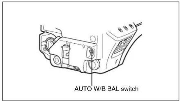
The switch will return to the center position, and adjustment will be performed.
During adjustment, a message like the one in the figure below will be displayed on the viewfinder screen.
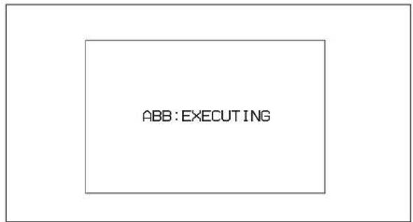
When the adjustment process is completed, the message "ABB: OK" will be displayed. The adjusted value is automatically stored in memory.
Notes
- During black balance adjustment, the iris will be automatically closed.
- During black balance adjustment, the gain switching circuit will work automatically, and the viewfinder screen will flicker several times. This is not a malfunction.
When automatic black balance adjustment fails
If the automatic black balance adjustment process does not end successfully, the error message "ABB: NG" will be displayed on the viewfinder screen for approximately three seconds.
If this error message is displayed, try black balance adjustment again.
If the error message continues to be displayed after several attempts, the camera requires internal inspection.
About black balance memory
The black balance values stored in memory will be preserved even when the camera power is turned off.
Adjusting the white balance
Automatic adjustment of white balance is performed with the following procedure:
Procedure for adjusting the white balance
1 Set the WHITE BAL switch to A or B.
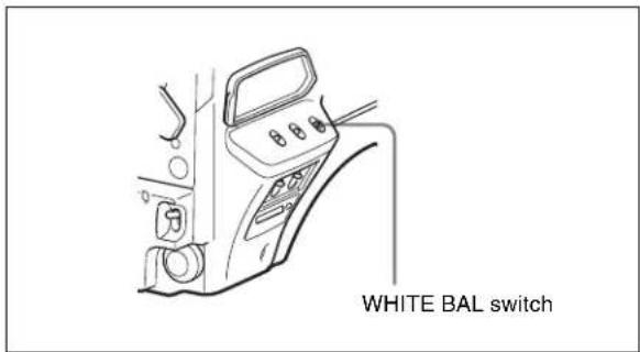
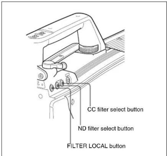
2 Select the filter setting according to the lighting conditions.
HDC1500/1550
To select the ND filter
Press the ND filter select button while holding the FILTER LOCAL button depressed.
Each press of the select button switches the available ND filters (clear, 1/4ND, 1/8ND, 1/16ND, 1/64ND) in sequence.
To select the CC filter
Press the CC filter select button while holding the FILTER LOCAL button depressed.
Each press of the select button switches the available CC filters (cross, 3200K, 4300K, 6300K, 8000K) in sequence.
| ND Filter Color temperature | conversion filter | ||
| 1 clear | A cross filter | ||
| 2 1/4 | ND B 3200K (clear) | ||
| 3 1/8 | ND C 4300K | ||
| 4 1/16 | ND D 6300K | ||
| 5 1/64 | ND E 8000K | ||
HDC1400/1450
Press the filter select UP or DOWN button while holding the FILTER LOCAL button depressed. Each press of the UP or DOWN button switches the available optical filters in sequence.
| Optical Filter | |||
| 1 clear | |||
| 2 1/4 ND | |||
| 3 | 1 | / | 1 |
| 4 | 1 | / | 6 |
| 5 | c | r | o |
| 6 | N |
| 4 | N |
| s | s |
3 Place a white pattern in the same lighting conditions as the subject, and zoom in on it so that a white area is obtained in the screen to satisfy the positional and quantitative requirements illustrated below.
A white object (white cloth, a white wall, etc.) near the subject may be used in place of a white pattern.
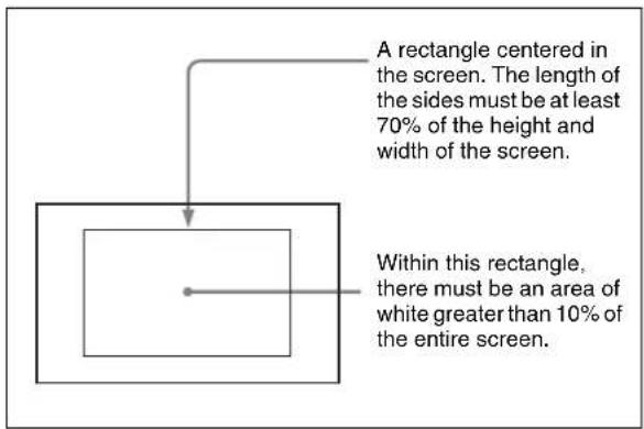
Note
Be careful not to have any spots of high illumination in the rectangle.
4 Adjust the lens iris opening.
With a manually adjusted lens: Set the opening to an appropriate value.
With a lens which has automatic iris control: Set the lens' automatic/manual iris control switch to automatic.
5 Push the AUTO W/B BAL switch to WHT and release the switch.
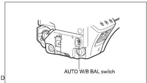
D
The switch will return to the center position, and adjustment will be performed.
During adjustment, the message “AWB: EXECUTING” will be displayed on the viewfinder screen.
After about one second, a message like the one in the figure below will be displayed, and the adjustment process will complete. The adjusted value will be automatically stored in the memory (A or B) selected in step 1.
AWB:OK
Note
When using a zoom lens with automatic iris control capability, hunting ^1) may occur. Adjust the lens' iris gain control (labeled IG, IS, S, etc.).
1) Hunting: The automatic iris responds over and over, and the image repeatedly darkens and lightens.
For more information, refer to the lens' operation manual.
When automatic white balance adjustment fails
If the white balance adjustment process does not end successfully, the error message "AWB: NG" will be displayed on the viewfinder screen for approximately three seconds.
If this error message is displayed, try white balance adjustment again.
If the error message continues to be displayed after several attempts, the camera requires internal inspection.
When there is no time to adjust the white balance
Set the WHITE BAL switch to PRST. The white balance will be set automatically according to the filter settings.
About white balance memory
The white balance values stored in memory will be preserved even when the camera power is turned off. There are two white balance memories, A and B. When the AUTO W/B BAL switch is pushed to the WHT side, the white balance will be adjusted automatically according to the filter settings. The adjusted value will be stored in the selected memory. Each memory can store up to five adjusted values, for a total of 10.
Setting the Electronic Shutter
This section explains the different modes which can be used for the electronic shutter, and gives the procedures for setting the shutter mode and shutter speed.
Note
When a camera control unit or a remote control device, such as MSU-900/950 and the RCP-700/900-series Remote Control Panel, is connected, the electronic shutter
is controlled from the external control device and control on the camera are disabled.
About the shutter modes
The shutter modes that can be used with the electronic shutter of the camera and the shutter speeds that may be selected are as follows:
Shutter modes and speeds
| Shutter mode | Shutter speeds1) | Usage |
| Standard 1/100, | 1/125, 1/250, 1/500, 1/1000, 1/2000 second | Use to obtain clear images of quickly moving subjects |
| ECS (Extended Clear Scan) | Continuously variable in the range of 60.0 Hz to 4300 Hz | Use to obtain images of computer monitors without horizontal striping |
1) The values in the table are those with 60i/59.94i. With other formats, the available values may be different.
Note
With artificial lighting, particularly fluorescent lights and mercury vapor lamps, the brightness appears to be constant, but in fact the strength of the red, green, and blue components varies with the power supply frequency. This phenomenon is known as “flicker.” When using the electronic shutter under these lighting conditions, there are certain cases in which the flicker is more noticeable. In particular, color flicker is evident when the power frequency is 60 Hz. In areas where the power frequency is 50 Hz, setting the shutter speed to 1/100 second will reduce the flicker.
Selecting the shutter mode and speed
The shutter mode, and the shutter speed in standard mode, are set using the SHUTTER switch.
Setting the shutter mode, and shutter speed in standard mode
1 Push the SHUTTER switch from the ON position to the SEL position.
The current shutter setting will be displayed in the setting change/adjustment progress message display area of the viewfinder screen for about three seconds.
Example: "Shutter: 1/250"
2 Push the SHUTTER switch to the SEL position again before the display disappears. Repeat this action until the desired mode or speed is displayed.
When all modes and speeds are displayed, they will be displayed in the following order:
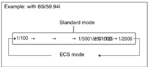
flowchart
graph LR
    A["Standard mode"] --> B["1/100"]
    B --> C["→"]
    C --> D["→"]
    D --> E["1/5001/2501.0135"]
    E --> F["1/2000"]
    G["ECS mode"] --> H["←"]
    style A fill:#f9f,stroke:#333
    style G fill:#f9f,stroke:#333
Setting the Camera Outputs
You can specify video signals directly output from the camera, with menu operations.
Note
The MAIN (camera picture), RET (return video), or VF (the same picture as that displayed on the viewfinder) setting is common to SD SDI and VBS. Different signals cannot be output.
The menu pages used for the output settings have been registered to the USER menu at the factory.
(HDC1500)/ (HDC1550/1400/1450)
•
Set the following menu items to the settings shown in the table.
For details on menu operations and the USER menu, see "Menu Operations" on page 88.
Outputting the signal being shot (camera picture)
The same character information as that displayed on the viewfinder can be added to the output signal by setting CHARACTER to "ON" on the
To output as HD SDI
| Menu page Item Setting | ||
| SDI-2 OUT (HDC1500)/SDI OUT(HDC1550/1400/1450) | OUT (HDC1500)/SDI OUT(HDC1550/1400/1450) | ACTIVE |
| (HDC1500)(HDC1550/1400/1450) | OUTPUT MAIN |
To output as SD SDI
| Menu page Item Setting | ||
| SDI-2 OUT(HDC1500)/SDI OUT(HDC1550/1400/1450) | ACTIVE | |
| DOWN CONVERTER ACTIVE | ||
| OUTPUT SIGNAL MAIN | ||
| (HDC1500) | OUTPUT SD-SDI | |
| (HDC1550/1400/1450) |
To output as VBS
| Menu page Item Setting | ||
Constantly outputting a return video
- When a camera control unit is connected, one of the signals being supplied to the camera control unit can be output from the camera.
- The last selected return signal is output.
- The same character information as that displayed on the viewfinder can be added to the output signal by setting CHARACTER to “ON” on the
( ) or page.
To output as HD SDI
| Menu page Item Setting | ||
| SDI-2 OUT (HDC1500)/SDI OUT(HDC1550/1400/1450) | ACTIVE | |
| (HDC1500)(HDC1550/1400/1450) | OUTPUT RET | |
To output as SD SDI
| Menu page Item Setting | ||
| SDI-2 OUT | UT (HDC1500)/SDI OUT(HDC1550/1400/1450) | ACTIVE |
| DOWN CONVERTER ACTIVE | ||
| OUTPUT SIGNAL RET | ||
| (HDC1500)/(HDC1550/1400/1450) | OUTPUT SD-SDI | |
To output as VBS
| Menu page Item Setting | ||
Outputting the same image as that on the viewfinder
- With HD SDI, you can obtain a signal that includes the same information as that being displayed on the viewfinder according to the settings of the VF MARKER, CHARACTER, VF DETAIL, ZEBRA, etc. The ON/OFF or other settings for adding information are common to those for the viewfinder. The output is synchronized with switching among Y, R, G, and B or switching to a return signal.
- With SD SDI or VBS, the output is synchronized only with switching between a return signal and the camera image. It does not correspond to switching among Y, R, G, and B. Information other than CHARACTER (such as VF MARKER, VF DETAIL, ZEBRA) cannot be added to the output.
Note
With the settings for outputting the same image as that on the viewfinder, the output will be obtained in 1080i, even if the format setting is 720P.
To output as HD SDI
| Menu page Item Setting | ||
| SDI-2 OUT(HDC1500)/SDI OUT(HDC1550/1400/1450) | (HDC1500)/SDI OUT(HDC1550/1400/1450) | ACTIVE |
| (HDC1500)(HDC1550/1400/1450) | OUTPUT VF |
To output as SD SDI
| Menu page Item Setting | ||
| SDI-2 OUT | (HDC1500)/SDI OUT(HDC1550/1400/1450) | ACTIVE |
| DOWN CONVERTER ACTIVE | ||
| OUTPUT SIGNAL VF | ||
| (HDC1500)(HDC1550/1400/1450) | OUTPUT SD-SDI | |
To output as VBS
| Menu page Item Setting | ||
| DOWN CONVERTER ACTIVE | ||
| OUTPUT SIGNAL VF | ||
| OUTPUT VBS |
Outputting via Dual Link (HDC1500 only)
The SDI-1 output is assigned to Link A, SDI-2 output to Link B.
Note
This function cannot be used when a camera control unit is connected.
To output in 1080/59.94P or 1080/50P
| Menu page Item Setting | ||
| ACT | VE LINE 1080 | |
| (Format) 59.94P or 50P | ||
| SDI-2 OUT | UT ACTIVE | |
| OUTPUT LINK-B | ||
Viewfinder Screen Status Display
Besides the video image, the viewfinder can display text and messages showing the camera settings and operation
status, as well as items such as a center marker or safety zone marker.
When the DISPLAY switch is set to ON
Items set to ON using the menu or related switches will be displayed on the upper and lower edges of the screen.
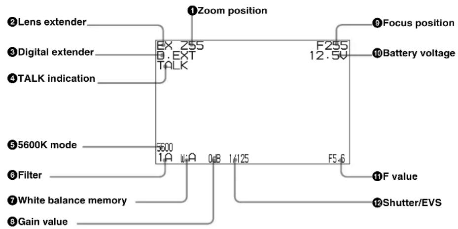
①Zoom position
Indicates the approximate position of the zoom lens variator between wide angle (0) and telephoto (99). Shows how close it is to the telephoto side.
② Lens extender
“EX” is displayed when a lens extender is in use.
③Digital extender (HDC1500/1550 only)
“D.EXT” is displayed when a digital extender is in use.
④ TALK indication
Displayed when the intercom microphone is set to ON.
55600K mode
Displayed when 5600K is set to ON.
6Filter
Displays the type of filter currently selected. The number (1, 2, 3, 4, or 5) indicates the ND filter, and the letter (A, B, C, D or E) is for the CC filter (HDC1500/1550 only).
⑦ White balance memory
Displays the currently selected white balance automatic adjustment memory.
W:A: The WHITE BAL switch is set to "A"
W:B: The WHITE BAL switch is set to "B"
W:P: The WHITE BAL switch is set to "PRST"
⑧Gain value
Displays the video gain value (dB) set with the GAIN switch.
⑨ Focus position
Shows the focus position of a zoom lens as a numeric value (0 to 255 (infinity)).
⑩Battery voltage
Displays the input voltage.
⑪F value
Indicates the lens F (iris opening) value.
⑫Shutter/EVS
Displays the shutter/EVS status. Nothing is displayed if both the electronic shutter and EVS are set to OFF.
When you press the CANCEL/STATUS switch toward STATUS
The status display is changed to show the following items:
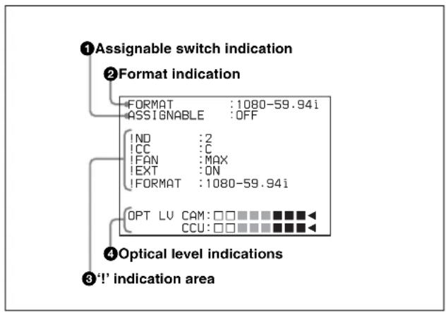
① Assignable switch indication
The function assigned to the assignable switch (page 68) is indicated.
For the functions that can be assigned, see OPERATION menu
②Format indication
The current video format is displayed.
③‘!’ indication area
This area is used to display abnormal statuses, using the <^! IND> function. Display options can be set, using the menu. (!CC is displayed for HDC1500/1550 only.)
For details, see OPERATION menu <‘!’ IND> (page 95).
④ Optical level indications (HDC1500/1400 only)
This area shows the input/output levels at the CCU connector (page 71), in segments.
CAM: Level of the output from the camera head
CCU: Level of the input to the camera head
Note
If a camera control unit other than an HDCU1000/1500 is connected, correct indications may not be obtained.
Menu Operations
The menus displayed on the viewfinder enable various settings of the camera.
The following controls are used to operate the menus.
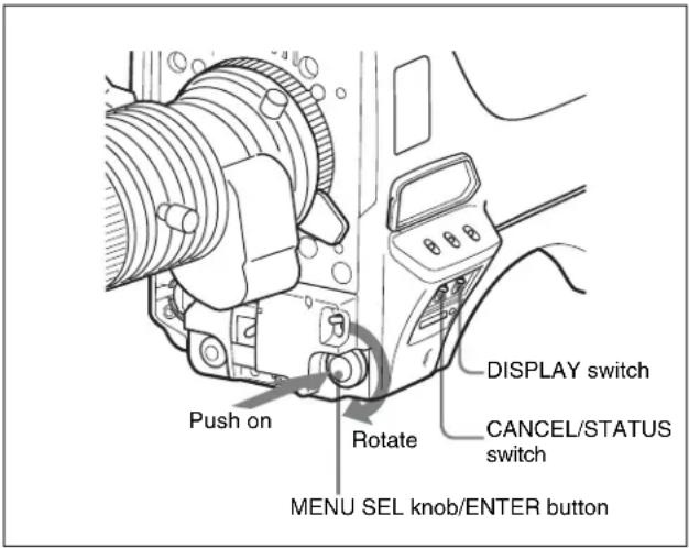
Starting Menu Operations
To display a menu page
Set the DISPLAY switch from OFF to MENU. The menu page that last operated will be displayed. (If it is the first time, the CONTENTS page of the OPERATION menu will be displayed.)
To display the TOP MENU screen
If you set the DISPLAY switch from OFF to MENU while holding the MENU SEL knob/ENTER button pressed, "TOP" is displayed at the upper right corner of the screen. Selecting it displays the TOP MENU screen, which lists the available menus, and you can select the menus on this screen.
TOP MENU screen
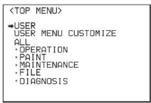
To disable the "TOP" indication
Turn the power once off then on again, or set the DISPLAY switch from OFF to MENU while holding the CANCEL/STATUS switch pressed toward CANCEL. This disables the TOP selection.
Available menus
USER menu
This menu can include menu pages selected from among the OPERATION, PAINT, MAINTENANCE, FILE, and DIAGNOSIS menus, for convenience. Changing, adding, and deleting pages can be performed with the USER MENU CUSTOMIZE menu.
USER MENU CUSTOMIZE menu
This menu allows you to edit the USER menu.
For details on the USER menu, see “Editing the USER Menu” on page 90.
ALL menu
This menu permits you to control all items of the OPERATION menu, PAINT menu, MAINTENANCE menu, FILE menu, and DIAGNOSIS menu as a single menu.
OPERATION menu
This menu contains items for camera operators to operate the camera. It mainly permits viewfinder, intercom, and switch settings.
PAINT menu
This menu contains items for making detailed image adjustments while using a waveform monitor to monitor the waveforms output from the camera. Support of a video engineer is usually required to use this menu.
Although you can also use an external remote control panel or master setup unit to set the items on this menu, the menu is effective when using the camera by itself outdoors.
MAINTENANCE menu
This menu contains items for performing camera maintenance operations, such as changing the system or setting infrequently used “paint” items.
FILE menu
This menu is for performing file operations, such as writing or clearing the reference file.
DIAGNOSIS menu
This menu enables you to confirm the self-diagnostic information.
To select a menu on the TOP MENU screen
1 Rotate the MENU SEL knob/ENTER button to align the arrow marker ( ) with the desired menu indication.
2 Push on the MENU SEL knob/ENTER button.
The CONTENTS page or the last operated page of the selected menu is displayed.
Selecting Pages
When selecting a page from a CONTENTS page
CONTENTS page (example)
If the screen can be scrolled, arrows will indicate the direction of scrolling.
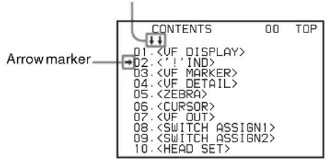
Rotate the MENU SEL knob/ENTER button to align the arrow marker ( ) with the desired page indication, then push on the MENU SEL knob/ENTER button.
The selected page is displayed.
![Page number → [04] TOP VF DETAIL : ON LEVEL : 25% CRISP : 0](/content/2026/05/815395/images/7d8ddef1721d4ae7e8dcfbcc9adf7b34177ff7f19a254130f25950022622da44.jpg)
To change the displayed page
1 Check that the arrow marker ( ) is located at the left of the page number, then push on the MENU SEL knob/ENTER button.
The arrow marker ( ) changes to a flashing question (?) mark.
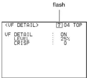
2 Rotate the MENU SEL knob/ENTER button to flip through the pages.
3 When the desired page is displayed, push on the MENU SEL knob/ENTER button.
The “?” mark will change back to the arrow marker (→), and operations with the displayed page are enabled.
To return to the TOP MENU screen
Align the arrow marker ( ) with “TOP” at the top right of the menu page then press the MENU SEL knob/ENTER button.
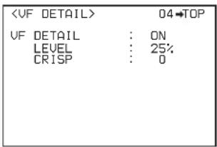
The TOP MENU screen is resumed.
Setting the Menu Items
If a “?” mark is flashing at the left of the page number, push on the MENU SEL knob/ENTER button to change it to the arrow marker (→). Setting on the displayed page is enabled.
1 Rotate the MENU SEL knob/ENTER button to align the arrow marker ( ) with the desired item.
2 Push on the MENU SEL knob/ENTER button.
The arrow marker ( ) will change to a flashing “?” mark.
3 Rotate the MENU SEL knob/ENTER button to change the setting value.
When the knob is rotated quickly, the values will change quickly; when rotated slowly, the values will change slowly.
To reset a changed value
If you press the CANCEL/STATUS switch toward CANCEL before pressing the MENU SEL knob/ENTER button, the setting will be returned to its previous value.
To interrupt settings
Set the DISPLAY switch to OFF to turn off the menu screen display.
The setting operation can be restarted by setting the DISPLAY switch back to MENU.
4 Push on the MENU SEL knob/ENTER button.
The “?” mark will change back to the arrow marker ( ), and the new setting will be registered.
5 To change other setting items on the same menu page, repeat steps 1 through 4.
To specify a character string
When you press the MENU SEL knob/ENTER button with the arrow marker (→) pointing to an item for which a character string, such as a file ID, is to be specified, a cursor and the list of selectable characters are displayed. The displayed cursor can be moved by rotating the MENU SEL knob/ENTER button.
1 Set the cursor to the position where you wish enter a character, then push on the MENU SEL knob/ENTER button.
Another cursor appears on the character list.
2 Set the cursor to the character to be entered and push on the MENU SEL knob/ENTER button.
Repeat steps 1 and 2.
By selecting INS on the line below the character list, you can enter a space at the cursor position.
Selecting DEL deletes the character at the cursor position.
You can return to step 1 without changing the character by selecting RET.
If you enter the permitted maximum number of characters (up to the stop mark at the right end of the line), the cursor moves to ESC on the line below the character list.
To register the new string you have set, select END and push on the MENU SEL knob/ENTER button.
To restore the previous string, select ESC and push on the MENU SEL knob/ENTER button.
To end menu operations
Set the DISPLAY switch to OFF.
Editing the USER Menu
You can select desired pages and items from the OPERATION, PAINT, MAINTENANCE, FILE, and DIAGNOSIS menus and register them to the USER menu. If you specify pages or items frequently used for the USER menu, you can easily call and use them.
The following pages are included on the factory-set USER menu:
For the items on each page, see the corresponding source menu page in the table in “Menu List” on page 94.
The USER MENU CUSTOMIZE menu allows you to configure a USER menu that consists only of pages and items that you need, by your adding, deleting or replacing pages.
Creating a new page
The USER MENU CUSTOMIZE menu allows you to add a new page to the USER menu.
While the EDIT page contains factory-preset items, the USER 1 EDIT to USER 19 EDIT pages are all blank in their initial state. You can register up to 10 items, including blank lines, on each of these pages.
To create a new page, proceed as follows.
1 While holding the CANCEL/STATUS switch pressed toward STATUS, move the DISPLAY switch from the OFF position to the MENU position.
The TOP MENU screen appears.
2 Turn the MENU SEL knob/ENTER button to move the arrow marker ( ) to “USER MENU CUSTOMIZE”, then push on the MENU SEL knob/ENTER button.
If this is the first time the USER MENU CUSTOMIZE menu has been displayed, the CONTENTS page of the menu appears.
| CONTENTS | E00 TOP |
| ↓↓ | |
| 01.EDIT PAGE | |
| 02.USER 1 EDIT | |
| →03.USER 2 EDIT | |
| 04.USER 3 EDIT | |
| 05.USER 4 EDIT | |
| 06.USER 5 EDIT | |
| 07.USER 6 EDIT | |
| 08.USER 7 EDIT | |
| 09.USER 8 EDIT | |
| 10.USER 9 EDIT |
If the USER MENU CUSTOMIZE menu has been used before, the page last accessed appears.
3 If the CONTENTS page is displayed, turn the MENU SEL knob/ENTER button to move the arrow marker (→) to any of USER 1 EDIT to USER 19 EDIT then push on the MENU SEL knob/ENTER button to display the page.
If a different page is displayed, turn the MENU SEL knob/ENTER button until the desired page appears, then push on the MENU SEL knob/ENTER button to select the page.
Example: When you select the USER 2 EDIT page
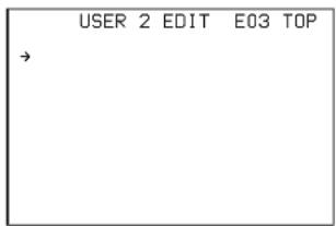
4 Move the arrow marker ( ) to the item to be added (this operation is unnecessary if no item exists on the page, as shown in the figure for step 3) then push on the MENU SEL knob/ENTER button.
The EDIT FUNCTION screen appears.
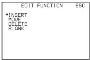
5 Move the arrow marker (→) to "INSERT" and push on the MENU SEL knob/ENTER button.
The page with the last item added appears.
| <SW STATUS> | P22 ESC |
| FLARE :→ ON | |
| GAMMA : ON | |
| BLK GAM : OFF | |
| KNEE : ON | |
| WHT CLIP : ON | |
| DETAIL : ON | |
| LUL DEP : ON | |
| SKIN DTL : OFF | |
| MATRIX : OFF |
6 Add the items.
①Turn the MENU SEL knob/ENTER button until the page that has the desired items appears, then push on the MENU SEL knob/ENTER button.
②Turn the MENU SEL knob/ENTER button to move the arrow marker ( ) to the desired item, then push on the MENU SEL knob/ENTER button.
The USER 2 EDIT page appears again, displaying the newly added item.
7 Add the remaining items by repeating steps 4 to 6.
You can add up to 10 items on one page.
To delete items from a page
Proceed as follows:
1 Move the arrow marker ( ) to the item to be deleted, and push on the MENU SEL knob/ENTER button.
The EDIT FUNCTION screen appears.
2 Select "DELETE," and push on the MENU SEL knob/ENTER button.
The previously displayed page appears again, and the message “DELETE OK? Yes No” appears at the upper right.
3 To delete, turn the MENU SEL knob/ENTER button to move the arrow marker ( ) to "YES," and push on the MENU SEL knob/ENTER button.
To change the order of items on a page
Proceed as follows:
1 Turn the MENU SEL knob/ENTER button to move the arrow marker ( ) to the item to be moved, then push on the MENU SEL knob/ENTER button.
The EDIT FUNCTION screen appears.
2 Select MOVE, then push on the MENU SEL knob/ENTER button.
The previously displayed page appears again.
3 Turn the MENU SEL knob/ENTER button to move the arrow marker (→) to the position where you wish to move the item, then push on the MENU SEL knob/ENTER button.
| ITEM MOVE | ESC | |
| ↓↓→UF OUT | : COLOR | |
| UF DETAIL | : OFF | |
| MARKER | : ON | |
| CURSOR | : OFF | |
| ZEBRA SW | : OFF | |
| : 1 | ||
| ●ASSIGNABLE | : OFF |
The item selected in step 1 moves to the position that you selected in step 3.
In the above example, "ASSIGNABLE" is moved to the top and the other items are moved down one line.
To insert a blank line
Proceed as follows:
1 Turn the MENU SEL knob/ENTER button to move the arrow marker (→) to the item above which you wish to insert a blank line.
The EDIT FUNCTION screen appears.
2 Select "BLANK" then push on the MENU SEL knob/ENTER button.
The previously displayed page appears again, and a blank line is inserted above the specified item.
Note
You cannot insert a blank line on a page where 10 items have already been registered.
Adding/deleting/replacing pages
You can add a new page to the USER menu, delete a page from the USER menu or replace pages, using the EDIT PAGE of the USER MENU CUSTOMIZE menu.
To add a page
Proceed as follows:
1 Select "USER MENU CUSTOMIZE" on the TOP MENU screen.
If this is the first time the USER MENU CUSTOMIZE menu has been displayed, the CONTENTS page of the menu appears. If the menu has been used before, the last accessed page appears.
2 If the CONTENTS page is displayed, turn the MENU SEL knob/ENTER button to move the arrow marker (→) to "EDIT PAGE", then push on the MENU SEL knob/ENTER button to display the EDIT PAGE screen.
If a different page is displayed, turn the MENU SEL knob/ENTER button until the EDIT PAGE screen appears, then push on the MENU SEL knob/ENTER button to select the page.
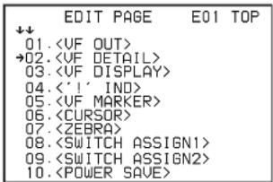
3 Turn the MENU SEL knob/ENTER button to move the arrow marker ( ) to where you wish to add the page, then push on the MENU SEL knob/ENTER button.
The EDIT FUNCTION screen appears.
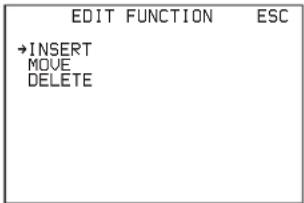
4 Select INSERT then push on the MENU SEL knob/ENTER button.
The selection screen appears.
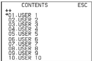
5 Turn the MENU SEL knob/ENTER button to move the arrow marker (→) to the desired page, then push on the MENU SEL knob/ENTER button.
This adds the number and name of the selected page above the item selected in step 3.
To cancel addition of a page
Before pushing the MENU SEL knob/ENTER button in step 5, turn the MENU SEL knob/ENTER button to move the arrow marker (→) to "ESC" at the top right of the screen, then push on the MENU SEL knob/ENTER button. The EDIT PAGE screen appears again.
To delete a page
Proceed as follows:
1 On the EDIT PAGE screen of the USER MENU CUSTOMIZE menu, move the arrow marker (→) to
the page to be deleted, and push on the MENU SEL knob/ENTER button.
The EDIT FUNCTION screen appears.
2 Select "DELETE" then push on the MENU SEL knob/ENTER button.
The previously displayed page appears again, and the message “DELETE OK?” appears at the upper right.
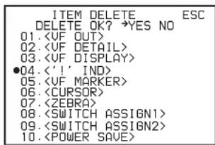
3 To delete, turn the MENU SEL knob/ENTER button to move the arrow marker (→) to "YES," then push on the MENU SEL knob/ENTER button.
To move a page
Proceed as follows:
1 Display the EDIT PAGE screen of the USER MENU CUSTOMIZE menu. Turn the MENU SEL knob/ENTER button to move the arrow marker (→) to the page that you wish to move.
The EDIT FUNCTION screen appears.
2 Select "MOVE" then push on the MENU SEL knob/ENTER button.
The EDIT PAGE screen appears again.
3 Turn MENU SEL knob/ENTER button to move the arrow marker ( ) to the position to which you wish to move the page selected in step 1.
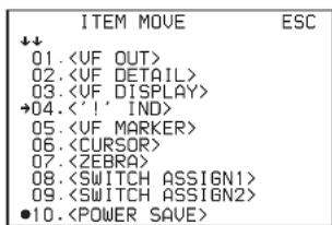
4 Push on the MENU SEL knob/ENTER button.
The page selected in step 1 is moved to the position selected in step 3.
In the above example,
Menu List
This section shows the menus to be displayed on the viewfinder in tables.
- For the pages that have been registered in the USER menu at the factory, the USER menu page numbers are indicated in parenthesis in the No. column of the tables.
- A CONTENTS page (numbered 00) is also provided for each menu.
Notes
HDLA: HDLA1500-series Large Lens Adaptor
CCU: HDCU1000/1500 Camera Control Unit
Execute by ENTER: Execute by pushing on the MENU SEL knob/ENTER button.
OPERATION Menu
| Page title | No. | Item | Default | Settings | Remarks |
| 01(U03) | EX ON ON, OFF | ||||
| ZOOM OFF ON, OFF | |||||
| DISP LEFT | LEFT, RIGT | ||||
| FOCUS | OFF | ON, OFF | Valid only when a serial lens is used | ||
| ND | ON ON, OFF | ||||
| CC | ON ON, OFF | Invalid with HDC1400/1450 | |||
| 5600K | ON ON, OFF | ||||
| IRIS | ON ON, OFF | ||||
| WHITE | OFF ON, OFF | ||||
| D.EXT | ON ON, OFF | Invalid with HDC1400/1450 | |||
| GAIN | ON ON, OFF | ||||
| SHUTT | ON ON, OFF | ||||
| BATT | OFF ON, OFF | ||||
| RETURN ON ON, OFF | |||||
| TALK ON ON, OFF | |||||
| MESSAGND [IND] ON ON, OFF | ALL[IND]: Set whether to be | ALL, WRN, AT, OFF | ALL: To display all messagesWRN: To display warning messages and higherAT: To display Auto Setup information and higherincluded in the status indications on the viewfinder (see page 88).[NORMAL]: Specify the conditions under which the '!' indication is not to be displayed even if [IND] is ON. (By specifying the standard or normal conditions here, non-standard or abnormal conditions can be found with the '!' indication on the viewfinder.)e.g.: With the default setting of ND, the '!' indication is displayed when an ND filter other than 1 is selected.- - - : When CCU connected (cannot be changed)NoteCC is available for HDC1500/1550 only. | ||
| 02(U04) | |||||
| [NORMAL] 1 - - - - | 1, 2, 3, 4, 5 (combination allowed) | ||||
| CC [IND] ON ON, OFF | |||||
| [NORMAL] - B - - - | A, B, C, D, E (combination allowed) | ||||
| WHITE [IND] ON ON, OFF, - - - | |||||
| [NORMAL] - A B P, A, B (combination allowed) | |||||
| 5600K [IND] ON ON, OFF, - - - | |||||
| [NORMAL] OFF ON, OFF | |||||
| GAIN [IND] ON ON, OFF, - - - | |||||
| [NORMAL] - - L | L, M, H (combination allowed) | ||||
| SHUTT [IND] ON ON, OFF, - - - | |||||
| [NORMAL] OFF ON, OFF | |||||
| FAN | [IND] ON ON, OFF | ||||
| [NORMAL] AUTO1 | AUTO1, AUTO2, MIN, MAX | ||||
| EXT | [IND] ON ON, OFF | ||||
| FORMAT | [IND] ON ON, OFF | ||||
| [NORMAL] 59.94i or 50i (HDC1400 CE/E33 and HDC1450 CE models) | HDC1500/1550:59.94i, 29.97PsF, 50i,25PsF, 24PsF, 23.98PsF,59.94P, 50PHDC1400 JN3/JN4 and HDC1450 UC models:59.94i, 59.94PHDC1400 CE/E33 and HDC1450 CE models:50i, 50P | ||||
| 03(U05) | MARKER | ON | ON, OFF Except MASK | ||
| CENTER | OFF | ON, OFF | |||
| 1 | 1, 2, 3, 4 | 1: Entire cross2: Entire cross with a hole3: Center4: Center with a hole | |||
| SAFETY ZONE | OFF | ON, OFF | |||
| 90.0% 80.0, 90.0, 92.5 | 95.0% | ||||
| EFFECT | OFF | ON, OFF | |||
| ASPECT | OFF | ON, OFF | |||
| 4:3 | 16:9, 15:9, 14:9, 13:9, 4:3,(4.3) | (4.3): If VF SCAN is set to 4:3 on HDLA attached (cannot be changed) | |||
| MASK | OFF | ON, OFF, (ON) | (ON): If VF SCAN is set to 4:3 on HDLA attached (cannot be changed) | ||
| 12 | 0 to 15 | Set the level to darken outside the aspect area. | |||
| SAFETY | OFF | ON, OFF For the safety marker in Aspect mode | |||
| 90.0% 80.0, 90.0, 92.5 | 95.0% | ||||
| 04(U02) | VF DETAIL | ON | ON, OFF | ||
| LEVEL | 25% | 0 to 100% | |||
| CRISP | 0 | -99 to +99 | |||
| FREQUENCY | 9M | 9M, 14M, 18M | |||
| 05(U07) | ZEBRA OFF ON, OFF | ||||
| 1 1, 2, 1&2 | |||||
| ZEBRA1 LEVEL 70% 50 to 109% | |||||
| WIDTH 10% 0 to 30 % | |||||
| ZEBRA2 100% 50 to 109% | |||||
| 06(U06) | CURSOR OFF ON, OFF display only if HDLA attached | ||||
| BOX/CROSS BOX BOX, CROSS | |||||
| H POSITION 50 0 to 99 | display only if HDLA attached | ||||
| V POSITION 50 0 to 99 | |||||
| WIDTH 50 0 to 99 | |||||
| HEIGHT | 50 0 to 99 | ||||
| 07(U01) | VF OUT | COLOR | COLOR, Y, R, G, B,(COLOR), (Y), (R), (G), (B),(RET), (VF), (R+G), (R+B),(G+B) | Settings in ( ): When HDLA attached (cannot be changed) | |
| RET MIX VF | OFF | ON, OFF, (ON), (OFF) | Settings in ( ): When HDLA attached (cannot be changed) | ||
| MIX DIRECTION RET MAIN, RET | |||||
| MIX VF MODE | Y-MIX | Y-MIX, WIRE(W), WIRE(B) | |||
| MIX VF LEVEL | 80% 0 to 80% | ||||
| 08(U08) | GAIN | [L] 0 dB | -3, 0, 3, 6, 9, 12 dB | ||
| [M] 6 dB | -3, 0, 3, 6, 9, 12 dB | ||||
| [H] 12 dB | -3, 0, 3, 6, 9, 12 dB | ||||
| ASSIGNABLE | OFF OFF, RETURN1 S W,RETURN2 SW, INCOM1,INCOM2, VF DETAIL,MIX VF, 5600K, FAN MAX,D.EXTENDER | When HDLA attached: OFF,EXTENDER, 5600K, FANMAX, D.EXTENDERNotesWhen you turnD.EXTENDER ON or OFF,noise may be generated.This is not a malfunction.D.EXTENDER cannot be selected on HDC1400/1450. | |||
| RE.ROTATION | STD | STD, RVS | Specify operation mode of the MENU SEL knob.STD: Clockwise rotationmoves → down orincreases values on themenu screen.RVS: Counterclockwiserotation moves → down orincreases values on themenu screen. | ||
| 09 (U09) | LENS VTR S/S RETURN | N2 SW OFF, RETURN1 | SW,RETURN2 SW, INCOM1,INCOM2 | Assign a function to the VTR START/STOP switch on the mounted lens. | |
| FRONT RET1 RETURN | 1 SW OFF, RETURN1 | SW,RETURN2 SW, INCOM1,INCOM2, D.EXTENDER | D.EXTENDER cannot be selected on HDC1400/1450. | ||
| FRONT RET2 RETURN | 2 SW OFF, RETURN1 | SW,RETURN2 SW, INCOM1,INCOM2, D.EXTENDER | D.EXTENDER cannot be selected on HDC1400/1450. | ||
| HANDLE SW1 RETURN | 1 SW OFF, RETURN1 | SW,RETURN2 SW, INCOM1,INCOM2, ZOOM(T) | |||
| HANDLE SW2 INCOM1 | OFF, RETURN1 SW, | RETURN2 SW, INCOM1,INCOM2, ZOOM(W) | |||
| ZOOM SPEED 20 00 to 99 | |||||
| HKCT INCOM MIC INCOM1 INCOM1, INCOM2 | UC/SYL/JN3/JN4 models | only.Assign a function to the INTERCOM MIC switch on the HKC-T1500. | |||
| ENG ENG, PROD CE/E33 models only. | Assign a function to the INTERCOM MIC switch on the HKC-T1500. | ||||
| 10 (U12) | INTERCOM1 MIC | CARBON | DYNAMIC, CARBON, MANUAL | ||
| LEVEL | (-20 dB) | -60 dB, -50 dB, -40 dB,-30 dB, -20 dB | Settings in ( ): With DYNAMIC or CARBON (cannot be changed) | ||
| 0 dB | -6 dB, 0 dB, +6 dB | Input gain | |||
| POWER (OFF) | ON, OFF, (ON), (OFF) Settings in ( ): With DYNAMIC or CARBON (cannot be changed) | ||||
| UNBAL | (OFF) | ON, OFF, (ON), (OFF) | Settings in ( ): With CARBON (cannot be changed) | ||
| INTERCOM2 MIC | CARBON | DYNAMIC, CARBON, MANUAL | |||
| LEVEL | (-20 dB) | -60 dB, -50 dB, -40 dB,-30 dB, -20 dB | Settings in ( ): With DYNAMIC or CARBON (cannot be changed) | ||
| 0 dB | -6 dB, 0 dB, +6 dB | Input gain | |||
| POWER (OFF). | ON, OFF, (ON), (OFF) Settings in ( ): With DYNAMIC or CARBON (cannot be changed) | ||||
| UNBAL | (OFF) | ON, OFF, (ON), (OFF) | Settings in ( ): With CARBON (cannot be changed) | ||
| 11 (U13) | SIDE TONE | ||||
| INTERCOM1 | 50 MU, 1 to 99 | ||||
| INTERCOM2 | 50 MU, 1 to 99 | ||||
| 12 INTERCOM1 | SEPARATE SEPARATE, MIX | ||||
| INTERCOM LEFT RIGHT, LEFT, BOTH, -- - UC/SYL/JN3/JN4 models only | |||||
| ENG LEFT RIGHT, LEFT, BOTH, -- - CE/E33 models only | |||||
| PROD LEFT RIGHT, LEFT, BOTH, -- - CE/E33 models only | |||||
| PGM1 RIGHT RIGHT, LEFT, BOTH, -- | |||||
| PGM2 RIGHT RIGHT, LEFT, BOTH, -- | |||||
| TRACKER LEFT RIGHT, LEFT, BOTH, -- | |||||
| 13 INTERCOM2 | SEPARATE SEPARATE, MIX | ||||
| INTERCOM LEFT RIGHT, LEFT, BOTH, -- - UC/SYL/JN3/JN4 models only | |||||
| ENG LEFT RIGHT, LEFT, BOTH, -- - CE/E33 models only | |||||
| PROD LEFT RIGHT, LEFT, BOTH, -- - CE/E33 models only | |||||
| PGM1RIGHT RIGHT, LEFT, BOTH, -- | |||||
| PGM2RIGHT RIGHT, LEFT, BOTH, -- | |||||
| TRACKER -- | RIGHT, LEFT, BOTH, -- | ||||
| 14 TRACKER RECEIVE SEL | SEPARATE SEPARATE, MIX | ||||
| INTERCOM LEFT RIGHT, LEFT, BOTH, -- - UC/SYL/JN3/JN4 models only | |||||
| ENG LEFT RIGHT, LEFT, BOTH, -- - CE/E33 models only | |||||
| PROD LEFT RIGHT, LEFT, BOTH, -- - CE/E33 models only | |||||
| PGM1 Right RIGHT, LEFT, BOTH, -- | |||||
| PGM2 RIGHT RIGHT, LEFT, BOTH, -- | |||||
| 15 EARNPHONE | SEPARATE SEPARATE, MIX | ||||
| INTERCOM LEFT RIGHT, LEFT, BOTH, -- - UC/SYL/JN3/JN4 models only | |||||
| ENG LEFT RIGHT, LEFT, BOTH, -- - CE/E33 models only | |||||
| PROD LEFT RIGHT, LEFT, BOTH, -- - CE/E33 models only | |||||
| PGM1Right RIGHT, LEFT, BOTH, -- | |||||
| PGM2RIGHT RIGHT, LEFT, BOTH, -- | |||||
| TRACKER LEFT RIGHT, LEFT, BOTH, -- | |||||
| 16 | READ (MS→CAM) | Execute by ENTER. | To read the operator file from a “Memory Stick” | ||
| WRITE (CAM→MS) | Execute by ENTER. | To write the current settings of the operator file items to a “Memory Stick” | |||
| PRESET | Execute by ENTER. | To set the operator file items to the preset values in internal memory | |||
| FILE ID | alphanumerics (max.16 characters) | Enter a comment for the operator file to be written to a “Memory Stick.”See “To specify a character string” on page 90. | |||
| CAM CODE | HDCxxxx | Camera code | display only | ||
| DATE | display only | ||||
| 17(U11) | FILE 1 1 to 16 | ||||
| xxxx... Lens file name display only | |||||
| F.xx F-stop number of the lens display only | |||||
| CENTER MARKER To set and store the center | marker position:H POS: Increasing the value moves it to the right.V POS: Increasing the value moves it downwards. | ||||
| H POS 0 -20 to +20 | |||||
| V POS 0 -20 to +20 | |||||
| STORE CENTER Execute by ENTER. | |||||
PAINT Menu
| Menu page | No. | Item/ | Default | Settings | Remarks |
| P01 | FLARE | ON | ON, OFF | ||
| GAMMA | ON | ON, OFF | |||
| BLK GAM | OFF | ON, OFF | |||
| KNEE | ON | ON, OFF | |||
| WHT CLIP | ON | ON, OFF | |||
| DETAIL | ON | ON, OFF | |||
| LVL DEP | ON | ON, OFF | |||
| SKIN DTL | OFF | ON, OFF | |||
| MATRIX | OFF | ON, OFF | |||
| P02 | WHITE | [R] [G] [B] [M]0 0 0 | -99 to +99 | R, G, B, and M (master) values can be independently set.(M cannot be set for WHITE or FLARE.) | |
| BLACK | 0 0 0 0 | -99 to +99 | |||
| FLARE | 0 0 0 | -99 to +99 | |||
| GAMMA | 0 0 0 0 | -99 to +99 | |||
| V MOD | 0 0 0 0 | -99 to +99 | |||
| FLARE | ON | ON, OFF | |||
| V MOD | ON | ON, OFF | |||
| D. SHAD | OFF | ON, OFF | |||
| TEST | OFF | OFF, SAW, 3STEP, 10STEP | |||
| P03 | LEVEL | [R] [G] [B] [M]0 0 0 0 | -99 to +99 | R, G, B, and M (master) values can be independently set. | |
| COARSE | 0.45 | 0.35 to 0.90 (0.05 steps) | |||
| TABLE | STANDARD | STANDARD, HYPER | |||
| 5 | 1, 2, 3, 4, 5, 6, 7 | With STANDARD selected1: equivalent to a camcorder2: 4.5-times gain3: 3.5-times gain4: equivalent to SMPTE-240M5: equivalent to ITU-R7096: 5.0-times gain7: 5.0-times gain - 709With HYPER selected1: 325% to 100%2: 460% to 100%3: 325% to 109%4: 460% to 109% (default)(5 to 7 are not selectable) | |||
| GAMMA | ON | ON, OFF | |||
| TEST | OFF | OFF, SAW, 3 STEP, 10 STEP | |||
| LEVEL | [R] [G] [B] [M]0 0 0 0 | -99 to +99 | R, G, B, and M (master) values can be independently set. | ||
| RANGE HIGH LOW, L | MID, H.MID, HIGH | ||||
| OFF ON, OFF | |||||
| TEST OFF OFF, SAW, 3 STEP, 10 STEP | |||||
| P05 SATURATION 0 -99 to +99 | |||||
| SW OFF ON, OFF | |||||
| LOW KEY SAT 0 -99 to +99 | |||||
| RANGE HIGH LOW, L.MID, H.MID, HIGH | |||||
| SW OFF ON, OFF | |||||
| TEST OFF OFF, SAW, 3 STEP, 10 STEP | |||||
| K POINT | [R] [G] [B] [M]0 0 0 0 | -99 to +99 | R, G, B, and M (master) values can be independently set. Absolute values are displayed in ABS mode except for M (master). | ||
| K SLOPE | 0 0 0 0 | -99 to +99 | |||
| KNEE | ON ON, OFF | ||||
| KNEE MAX | OFF ON, OFF | ||||
| KNEE SAT | 0 -99 to +99 | ||||
| OFF ON, OFF | |||||
| AUTO KNEE | OFF | OFF, AUTO, ADAPTIVE | |||
| POINT LIMIT | 0 | -99 to +99 | Absolute value is displayed in ABS mode. | ||
| SLOPE | 0 | -99 to +99 | Absolute value is displayed in ABS mode. | ||
| ABS | Highlighted: ABS (Absolute) mode | ||||
| P07 | W CLIP | [R] [G] [B] [M]0 0 0 0 | -99 to +99 | R, G, B, and M (master) values can be independently set. Absolute values are displayed in ABS mode except for M (master). | |
| ON ON, OFF | |||||
| ABS | Highlighted: ABS (Absolute) mode | ||||
| P08 DETAIL ON ON, OFF | |||||
| LEVEL | 0 | ||||
| LIMITER M | 0 | ||||
| LIMITER WHT | 0 | ||||
| LIMITER BLK | 0 | ||||
| CRISP | 0 | ||||
| LVL DEP | 0 | ||||
| ON ON, OFF | |||||
| ABS | |||||
| P09 | H/V RATIO | 0 | -99 to +99 | Absolute value is displayed in ABS mode. | |
| FREQ 0 -99 to +99 Absolute value is displayed in ABS | mode. | ||||
| MIX RATIO 0 -99 to +99 Absolute value is displayed in ABS | mode. | ||||
| KNEE APERTURE | 0 | -99 to +99 | Absolute value is displayed in ABS mode. | ||
| OFF ON, OFF | |||||
| ABS Highlighted: ABS | (Absolute) mode | ||||
| P10 SKIN DTL | OFF ON, OFF | ||||
| SKIN GATE OFF OFF, | 1, 2, 3 | 1, 2, 3: Skin gate can be set to ON for the specified channel only. | |||
| ABS Highlighted: ABS | (Absolute) mode | ||||
| CH SW | [1] [2] [3] (ON) OFF OFF | ON, OFF | Skin tone detail function can be independently set for each channel (channel 1 is always ON). | ||
| HUE | AUTO AUTO AUTO | Execute by ENTER. | Absolute values are indicated for LEVEL only in ABS mode. | ||
| PHASE | 0 0 0 | 0 to 359 | |||
| WIDTH | 29 29 29 | 0 to 359 | |||
| SAT | -89 -89 -89 | -99 to +99 | |||
| LEVEL | 0 0 0 | -99 to +99 | |||
| P11 | R-G | 0 | -99 to +99 | ||
| R-B | 0 -99 to +99 | ||||
| G-R | 0 -99 to +99 | ||||
| G-B | 0 -99 to +99 | ||||
| B-R | 0 -99 to +99 | ||||
| B-G | 0 -99 to +99 | ||||
| MATRIX | ON | ON, OFF | |||
| PRESET | ON | ON, OFF | Invalid when MATRIX is OFF | ||
| SMPTE-240M | SMPTE-240M, ITU-709, SMPTE-WIDE, NTSC, EBU, ITU-601 | ||||
| USER MATRIX | OFF ON, OFF | ||||
| MULTI MATRIX | OFF ON, OFF | ||||
| P12 | PHASE | 0 | 0, 23, 45, 68, 90, 113, 135, 158, 180, 203, 225, 248, 270, 293, 315, 338 | Select an axis (angle) at PHASE for which the multimatrix adjustment to be made, and set HUE and SAT. (HUE and SAT can be adjusted independently for 16 axes.) | |
| HUE | 0 -99 to +99 | ||||
| SAT | 0 -99 to +99 | ||||
| ALL CLEAR | Execute by ENTER. | ||||
| GATE | OFF ON, OFF | ||||
| MATRIX | ON | ON, OFF | |||
| PRESET | ON | ON, OFF | Invalid when MATRIX is OFF | ||
| ITU-709 | SMPTE-240M, ITU-709, SMPTE-WIDE, NTSC, EBU, ITU-601 | ||||
| USER | OFF ON, OFF | ||||
| MULTI | OFF ON, OFF | ||||
| Menu page | No. | Item/ | Default | Settings | Remarks | |
| P13 SHUTTER OFF ON, OFF | ||||||
| 1/100 (sec) 59.94i: | 1/100, 1/125, 1/250,1/500, 1/1000, 1/200050i: 1/60, 1/125, 1/250,1/500, 1/1000, 1/200029.97PsF: 1/40, 1/60, 1/120,1/125, 1/250, 1/500,1/100025PsF: 1/33, 1/50, 1/100,1/125, 1/250, 1/500,1/100024P/23.98P: 1/32, 1/48,1/96, 1/125, 1/250,1/500, 1/100059.94P: 1/100, 1/125, 1/250,1/500, 1/1000, 1/200050P: 1/60, 1/125, 1/250,1/500, 1/1000, 1/2000 | Step shutter settingNoteThere are some formats that cannot be selected on HDC1400/1450. | ||||
| ECS FREQ 59.94 Hz | 59.94i: 60.00 to 4300 | Hz50i: 50.00 to 4700 Hz29.97PsF: 30.00 to 2700 Hz25PsF: 25.00 to 2300 Hz24PsF/23.98PsF: 24.00 to2200 Hz59.94P: 60.02 to 4600 Hz50P: 50.03 to 4600 Hz | NoteThere are some formats that cannot be selected on HDC1400/1450. | |||
| P14 1 To store | and read scene files | (paint data):When storing a file in camera memory, specify the number before executing STORE.When reading, only specify the number. | ||||
| 2 | ||||||
| 3 | ||||||
| 4 | ||||||
| 5 | ||||||
| STORE Execute by ENTER. | ||||||
| STANDARD Execute by ENTER. To read the standard paint data | ||||||
| READ (MS→CAM) | Execute by ENTER. | To load five scene files from a “Memory Stick” to internal memory | ||||
| WRITE (CAM→MS) | Execute by ENTER. | To write five scene files in the camera’s memory to a “Memory Stick” | ||||
| FILE ID Max.16 characters Enter a comment for the scene | files to be written to a “Memory Stick.”See “To specify a character string” on page 90. | |||||
| CAM CODE | HDCxxxx | Camera code | display only | |||
| DATE | display only | |||||
| P15 | NOISE SUP | 0% | 0 to 100% | |||
| SW | OFF ON, OFF | |||||
MAINTENANCE Menu
| Menu page | No. | Item/ | Default | Settings | Remarks |
| M02 | [R] [G] [B] 0 0 0 | -99 to +99 | R, G, and B values can be independently set. | ||
| V SAW | |||||
| V PARA | 0 0 0 | -99 to +99 | |||
| H SAW | 0 0 0 | -99 to +99 | |||
| H PARA | 0 0 0 | -99 to +99 | |||
| WHITE | 0 0 0 | -99 to +99 | |||
| AUTO WHITE SHADING E | execute by ENTER. | ||||
| WHITE SHAD MODE | RB | RGB, RB | |||
| 3D WHITE SHAD | ON | ON, OFF | |||
| M03 | [R] [G] [B] [M] 0 0 0 | -99 to +99 | R, G, and B values can be independently set.M (master) value can also be set for BLACK. | ||
| V SAW | |||||
| V PARA | 0 0 0 | -99 to +99 | |||
| H SAW | 0 0 0 | -99 to +99 | |||
| H PARA | 0 0 0 | -99 to +99 | |||
| BLK SET | 0 0 0 | -99 to +99 | |||
| BLACK | 0 0 0 0 | -99 to +99 | |||
| MASTER GAIN | 0 dB | -3, 0, 3, 6, 9, 12 dB | |||
| AUTO BLACK SHADING E | execute by ENTER. | ||||
| 2D BLACK SHAD | ON | ON, OFF | |||
| M04 | PHASE | 0 | 0, 23, 45, 68, 90, 113, 135, 158, 180, 203, 225, 248, 270, 293, 315, 338 | To select an axis (angle) at PHASE for which the OHB matrix adjustment is to be made, and set HUE and SAT (HUE and SAT can be adjusted independently for 16 axes). | |
| HUE | 0 | -99 to +99 | |||
| SAT 0 | -99 to +99 | ||||
| ALL CLEAR | Execute by ENTER. | To clear the HUE and SAT values for all PHASE settings | |||
| OHB MATRIX | OFF | ON, OFF | |||
| MATRIX | ON | ON, OFF | |||
| M05 AUTO IRIS | OFF ON, OFF | ||||
| WINDOW 1 1, 2, 3, 4, 5, 6 | Select the auto iris windows: | 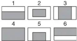 The shaded parts indicate the area where light detection occurs. The shaded parts indicate the area where light detection occurs. | |||
| OVERRIDE - - -99 to +99, | - To set the override to | temporarily change the reference value for brightness of the automatic iris level in the range of ±2 steps:-99: two steps to fully closed iris+99: two steps to fully open iris - - : OFFThe setting returns to “ - - ” when the power is turned off. | |||
| IRIS LEVEL 0 -99 to +99 ±4 steps | |||||
| APL RATIO 65 -99 to +99 | |||||
| IRIS GAIN 0 -99 to +99 | |||||
| IRIS CLOSE | OFF ON, OFF | ||||
| M06 (U14) | MIC1 | 60 dB | 20, 30, 40, 50, 60 dB | valid only in standalone operation | |
| MIC2 | 60 dB | 20, 30, 40, 50, 60 dB | |||
| M07 (U20) | TALLY BRIGHTNESS | 50 0 to 100 | |||
| NUMBER BRIGHTNESS | 50 0 to 100 | ||||
| CAMERA NUMBER | -- | -, 1 to 96 | |||
| NUMBER DISPLAY | AUTO | ON, OFF, AUTO | AUTO: to correspond to the UP TALLY switch setting of HDLA attached | ||
| M08 | CCU CALL | ON | ON, OFF | Invalid with CCU connected | |
| CAM CALL OFF ON, OFF | Invalid with CCU connected | ||||
| M09 (U15) | CURRENT | 1080-59.94i (V) | Displays the current format. | ||
| ACTIVE LINE | 1080 | 1080, 720 | The selectable frame settings are displayed for the selected ACTIVE LINE.(not displayed with CCU connected) | ||
| 59.94i | 1080: 24PsF, 59.94i, 29.97PsF, 23.98PsF, 59.94P, 50i, 25PsF, 50P720: 59.94P, 50P | ||||
| M09 (U15) | CURRENT | 1080-59.94i (V) | Displays the current format. | ||
| ACTIVE LINE | 1080 | 1080, 720 | The selectable frame settings are displayed for the selected ACTIVE LINE.(not displayed with CCU connected) | ||
| 59.94i | 1080: 59.94i, 29.97PsF, 23.98PsF, 50i, 25PsF, 24PsF720: 59.94P, 50P | ||||
| M09 (U15) | CURRENT | 1080-59.94i (V) | Displays the current format. | ||
| ACTIVE LINE | 1080 | 1080, 720 | The selectable frame setting is displayed for the selected ACTIVE LINE (not displayed with CCU connected) | ||
| 59.94i | 1080: 59.94i720: 59.94P | ||||
| M09 (U15) | CURRENT 1080-50i (V) Displays the current format. | ||||
| ACTIVE LINE 1080 1080, 720 The selectable frame setting is | displayed for the selected ACTIVE LINE (not displayed with CCU connected) | ||||
| 50i 1080: 50i | 720: 50P | ||||
| M10 (U18) | OUTPUT SIGNAL MAIN MAIN, RET, VF | ||||
| ASPECT SQ SQ, EC | |||||
| M11 (U16) | OUTPUT VF | SD-SYNC, HD-SYNC, VF, VBS | |||
| (PWR SAVE) | Displayed in POWER SAVE mode only | ||||
| VBS-OUT | |||||
| CHARACTER | OFF | ON, OFF | |||
| HD-SYNC-OUT | |||||
| V-PHASE | 0 | -127 to +127 | |||
| H-PHASE | 0 | -127 to +127 | |||
| M12 (U17) | OUTPUT MAIN | MAIN, VF, LINK-B, RET, SD-SDI | |||
| (PWR SAVE) | Displayed in POWER SAVE mode only | ||||
| CHARACTER | OFF | ON, OFF | Not displayed if OUTPUT is set to VF or LINK-B | ||
| M12 (U17) | OUTPUT MAIN | MAIN, VF, RET, SD-SDI | |||
| (PWR SAVE) | Displayed in POWER SAVE mode only | ||||
| CHARACTER | OFF | ON, OFF | Not displayed if OUTPUT is set to VF | ||
| M13 (U10) | SDI-2 OUT | PWR SAVE | PWR SAVE, ACTIVE | ||
| DOWN CONVERTER | ACTIVE | PWR SAVE, ACTIVE | |||
| M13 (U10) | SDI OUT | PWR SAVE | PWR SAVE, ACTIVE | ||
| DOWN CONVERTER | ACTIVE | PWR SAVE, ACTIVE | |||
| M14 (U19) | TRUNK | ON | ON, OFF | ||
| IF | 232c | 232c, 422a | |||
| M15 | REFERENCE | Condition of synchronisation | display only | ||
| GENLOCK | display only | ||||
| STATUS | |||||
| FORMAT | |||||
| PHASE | |||||
| V | 0 | -999 to +999 | |||
| HD H | 0 | -99 to +99 | |||
| SD H | 0 | -99 to +99 | |||
| M16 | DATE/TIME | yyyy/mm/dd hh: mm | 2000 to 2099 / 01 to 12 / 00 to 31, 00 to 23 : 00 to 59 | ||
| M17 | FAN MODE | AUTO1 | AUTO1, AUTO2, MIN, MAX | AUTO1: Normal rotation AUTO2: Slow rotation | |
| CAM BARS | OFF | ON, OFF | |||
| V DTL CREATION | NAM NAM, G, R+G | Y | |||
| DTL H/V MODE | H/V H/V, V only | ||||
| TEST 2 MODE | 3STEP | 3STEP, 10STEP | |||
| WHITE SETUP MODE | AWB AWB, A.LVL | ||||
| M18 DATE TYPE | 5 M/D/Y 1 Y/Mn/D | 2 Mn/D3 D/M/Y4 D/M5 M/D/Y6 M/D | Y: YearMn: Month (numeric)M: Month (character string)D: Day | ||
| WHITE MEMORY OFF ON, OFF Set to ON to use independent | white memory at each CC filter position (HDC1500/1550 only). | ||||
| F NO. DISP CONTROL CONTROL, RETURN Select the iris indication on the panel when AUTO IRIS is off:CONTROL: To display the value from the cameraRETURN: To display the value returned from the lens(When AUTO IRIS is on, the value returned from the lens is always displayed.) | |||||
FILE Menu
Five types of files can be used for easy adjustments of the camera; Operator, Reference, Scene, OHB, and Lens. You can store the items set with the OPERATION menu and customized USER menu in the Operator file.
For the specific items included in these files, refer to the Maintenance Manual.
| Menu page | No. | Item/ | Default | Settings | Remarks |
| F01 | READ (MS→CAM) | Execute by ENTER. | To read the operator file from a “Memory Stick” | ||
| WRITE (CAM→MS) | Execute by ENTER. | To write the current settings of the operator file items to a “Memory Stick” | |||
| PRESET | Execute by ENTER. | To set the operator file items to the preset values in internal memory | |||
| STORE PRESET FILE | Execute by ENTER. | To store the current settings of the operator file items in the operator file in internal memory. | |||
| FILE ID | max.16 characters | Enter a comment for the operator file to be written to a “Memory Stick.” See “To specify a character string” on page 90. | |||
| CAM CODE HDCxxxx | Camera code | display only | |||
| DATE | display only | ||||
| F02 1 To store | and read scene files | (paint data):When storing a file in camera memory, specify the number before executing STORE.When reading, only specify the number. | |||
| 2 | |||||
| 3 | |||||
| 4 | |||||
| 5 | |||||
| STORE Execute by ENTER. | |||||
| STANDARD Execute by ENTER. To read the standard paint data | |||||
| READ (MS→CAM) | Execute by ENTER. | To load five scene files from a "Memory Stick" to internal memory | |||
| WRITE (CAM→MS) | Execute by ENTER. | To write five scene files in the camera's memory to a "Memory Stick" | |||
| FILE ID Max.16 characters | Enter a comment for the scene | files to be written to a "Memory Stick."See "To specify a character string" on page 90. | |||
| CAM CODE HDCxxxx Camera code display only | |||||
| DATE display only | |||||
| F03 | STORE FILE | Execute by ENTER. | To store the current settings of the reference file items in the reference file in internal memory. | ||
| STANDARD Execute by ENTER. To read the standard values in | the reference file in internal memory. | ||||
| ALL PRESET | Execute by ENTER. To resume the factory-preset reference file | ||||
| READ (MS→CAM) | Execute by ENTER. | To load a reference file from a "Memory Stick" | |||
| WRITE (CAM→MS) | Execute by ENTER. | To write the current settings of the reference file items as a reference file to a "Memory Stick" | |||
| FILE ID Max.16 characters | Enter a comment for the | reference file to be written to a "Memory Stick."See "To specify a character string" on page 90. | |||
| CAM CODE HDCxxxx Camera code display only | |||||
| DATE display only | |||||
| F04 STORE FILE | Execute by ENTER. | ||||
| No. | 1 to 16 | ||||
| NAME | xxxxx... | ||||
| F NO | F1.7 | F1.0 to F3.4 | |||
| CENTER MARKER | |||||
| H POS | 0 | -20 to +20 | |||
| V POS | 0 | -20 to +20 | |||
| STORE | Execute by ENTER. | ||||
| F05 | STORE FILE | Execute by ENTER. | To store the offset values of the items specific to the CCD (No repeated store operation is necessary even if the CCD is reattached) | ||
| F06 PRESET OPERATOR Execute by ENTER. | |||||
| REFERENCE (ALL) Execute by ENTER. | |||||
| 10 SEC CLEAR OFF ON, OFF OFF: To exclude the 10 SEC | |||||
| LENS (CURRENT) Execute by ENTER. To return the settings of the | |||||
| OHB WHITE SHADE (ALL) | |||||
| OHB WHITE SHADE (3D) Execute by ENTER. To clear the 3D WHITE | |||||
| OHB BLACK SHADE Execute by ENTER. | |||||
| OHB ND OFFSET Execute by ENTER. | |||||
| OHB MATRIX | |||||
| M.S. FORMAT | |||||
DIAGNOSIS Menu
This menu is only for viewing and no setting is made using this menu.
| Menu page | No. | Item | Indication | Remarks |
| D01 | CCU→CAM | GREEN, YELLOW, RED, NG, NO SIGNAL | With CCU connected only | |
| CAM→CCU | GREEN, YELLOW, RED, NG, NO SIGNAL | With CCU connected only | ||
| D02 | ROM | Vx.xxx | ROM version | |
| OHB | OK, NG | |||
| DPR | OK, NG | |||
| VDA | OK, NG | |||
| DAP | OK, NG | |||
| AU | OK, NG | |||
| AT | OK, NG | |||
| PS | OK, NG | |||
| SDI | OK, NG | HDC1500/1400 only | ||
| TR | OK, NG | HDC1550/1450 only | ||
| D03 | TG | Vx.xxx | ||
| VDA | Vx.xxx | |||
| DAP | Vx.xxx | |||
| AT | Vx.xxx | |||
| SDI | Vx.xxx | |||
| D04 | AT | x.xx | ||
| HDLA | x.xx | With HDLA attached only |
Using a “Memory Stick”
When a “Memory Stick” is inserted in the camera, the file data can be stored on the “Memory Stick,” which enables you to share data among cameras.
Inserting a "Memory Stick"
Insert a “Memory Stick” with the label side up into the “Memory Stick” slot until it clicks and the access lamp lights in red.
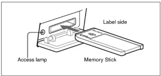
Access lamp
If the access lamp is lit or is flashing, data is being read from or written to the “Memory Stick.” At this time, do not shake the product or subject it to shock. Do not turn off the power of the product or remove the “Memory Stick.” This may damage the data.
What is "Memory Stick"?
“Memory Stick” is a new compact, portable and versatile IC (Integrated Circuit) recording medium with a data capacity that exceeds a floppy disk. “Memory Stick” is specially designed for exchanging and sharing digital data among “Memory Stick” compatible products. Because it is removable, “Memory Stick” can also be used for external data storage.
“Memory Stick” is available in two sizes: standard size and compact “Memory Stick Duo” size. Once attached to a “Memory Stick Duo” adapter, “Memory Stick Duo” turns to the same size as standard “Memory Stick” and thus can be used with products compliant with standard “Memory Stick”.
Types of "Memory Stick"
"Memory Stick" is available in the following types to meet various requirements in functions:
"Memory Stick-R"
Stored data are not overwritten. You can write data to "Memory Stick-R" with "Memory Stick-R" compatible products only. Copyright protected data that requires MagicGate copyright protection technology cannot be written to “Memory Stick-R.”
"Memory Stick"
Stores any type of data except copyright-protected data that requires the MagicGate copyright protection technology.
"MagicGate Memory Stick"
Equipped with the MagicGate copyright protection technology.
"Memory Stick-ROM"
Stores pre-recorded, read-only data. You cannot record on "Memory Stick-ROM" or erase the pre-recorded data.
"Memory Stick PRO"
"Memory Stick" with MagicGate copyright protection technology, exclusive for "Memory Stick PRO"-compliant products.
Usable types of "Memory Stick"
You can use a “Memory Stick,” a “MagicGate Memory Stick,” or a “Memory Stick PRO” with this product. However, the MagicGate copyright protection is not valid with this product.
Note
You cannot use a “Memory Stick Duo” without an appropriate adaptor.
Note on data read/write speed
Data read/write speed may vary depending on the combination of the “Memory Stick” and “Memory Stick” compliant product you use.
What is MagicGate?
MagicGate is copyright protection technology that uses encryption technology.
About a "Memory Stick"
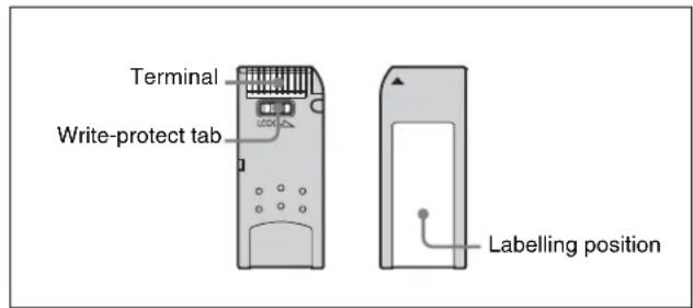
- When you set the “Memory Stick” erasure prevention switch to “LOCK,” data cannot be recorded, edited, or erased.
• Data may be damaged if:
—You remove the “Memory Stick” or turn off the unit while it is reading or writing data.
—You use the “Memory Stick” in a location subject to the effects of static electricity or electric noise.
- We recommend that you make a backup copy of important data that you record on the “Memory Stick”.
Notes
- Do not attach anything other than the supplied label to the "Memory Stick" labeling position.
- Attach the label so that it does not stick out beyond the labeling position.
- Carry and store the "Memory Stick" in its case.
- Do not touch the connector of the “Memory Stick” with anything, including your finger or metallic objects.
- Do not strike, bend, or drop the "Memory Stick".
- Do not disassemble or modify the "Memory Stick".
- Do not allow the "Memory Stick" to get wet.
- Do not use or store the “Memory Stick” in a location that is:
—Extremely hot, such as in a car parked in the sun
—Under direct sunlight
—Very humid or subject to corrosive substances
Precautions
- To prevent data loss, make backups of data frequently. In no event will Sony be liable for any loss of data.
- Unauthorized recording may be contrary to the provisions of copyright law. When you use a “Memory Stick” that has been pre-recorded, be sure that the material has been recorded in accordance with copyright and other applicable laws.
- The “Memory Stick” application software may be modified or changed by Sony without prior notice.
-
Note that there are certain restrictions on recording stage performances and other entertainment events, even if they are recorded for personal use only.
-
“Memory Stick”, and “MagicGate Memory Stick” are trademarks of Sony Corporation.
- "Memory Stick Duo" and MEMORY STICK DUO trademarks of Sony Corporation.
- "Memory Stick PRO" and MEMORY STICK PRO trademarks of Sony Corporation.
- "MagicGate" and MagicGate of Sony Corporation.
Specifications
HDC1500
General
Power requirements 240 V AC, 1.4 A (max.)
180 V DC, 1.0 A (max.)
12 V DC, 7 A (max.)
Operating temperature
-20^ to +45^ (-4^ to +113^)
Storage temperature -20^ to +60^ ( -4^ to +140^ )
Mass Approx. 4.5 kg (9 lb 15 oz) (camera
head only)
Imager
Imager 2/3-type Progressive Scan CCD
Method 3-CCD, RGB
Effective resolution 1920 (horizontal) × 1080 (vertical)
Electrical characteristics
Sensitivity f10.0 (at 2000 lx with 89.9%
reflectivity)
Image S/N Typical -54 dB/-62 dB (NS MAX)
Horizontal resolution
1000 TV lines (at center of screen)
5% or higher modulation
Registration 0.02% for total area (not including lens distortion)
Geometric distortion Negligible (not including lens distortion)
Optical system specifications
Spectral system F1.4 prism
Built-in filters Color temperature conversion filters
A: cross filter
B: 3200K (clear)
C: 4300K
D: 6300K
E: 8000K
ND filters
1: clear
2: 1/4 ND
3: 1/8 ND
4: 1/16 ND
5: 1/64 ND
Input/output connectors
CCU Optical/electrical multi-connector (1)
LENS 12-pin (1)
VF 20-pin (1)
MIC 1 IN XLR 3-pin, female (1)
AUDIO IN CH1, CH2
XLR 3-pin, female (1 each)
For MIC: -60 dBu (may be selected to -20 dBu by menu or
HDCU1000/1500 operations), balanced
For LINE: 0 dBu, balanced
INTERCOM1, INTERCOM2
XLR 5-pin, female (1 each)
EARPHONE Stereo minijack (1)
DC IN XLR 4-pin (1), 10.5 to 17 V DC
Dimensions
Unit: mm (inches)
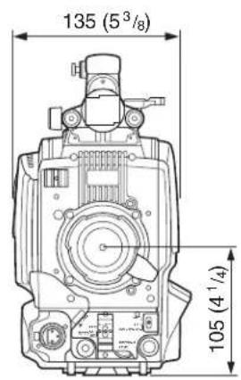
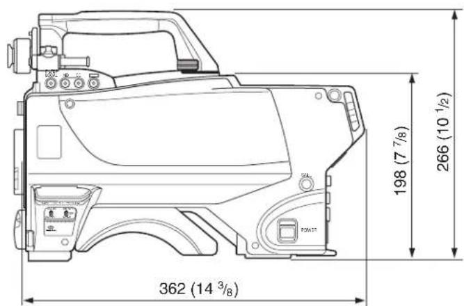
DC OUT 4-pin (1), 10.5 to 17 V DC, 1.5 A maximum It may be limited depending on the load and input conditions.
SDI 1, 2 BNC type (1 each)
TEST OUT BNC type (1)
GENLOCK IN/RET IN/PROMPTER
BNC type (1), 1 Vp-p, 75 ohms
PROMPTER2 BNC type (1), 1 Vp-p, 75 ohms
RET CTRL 6-pin (1)
REMOTE 8-pin (1)
TRACKER 10-pin (1)
CRANE 12-pin (1)
Supplied accessories
Operation manual (1)
Switch label 1, 2 (1 each)
Optional accessories
HDVF-20A HD Electronic Viewfinder (2-type, monochrome)
HDVF-C35W HD Electronic Viewfinder (3.5-type, color)
HDVF-C730W HD Electronic Viewfinder (6.3-type, color)
HDVF-C950W HD Electronic Viewfinder (9-type, color)
HDLA1500/1505 Large Lens Adaptor
HDLA1507 Large Viewfinder Adaptor
CAC-12 Microphone Holder
CAC-6 Return Video Selector
BKW-401 Viewfinder Rotation Bracket
VCT-14 Tripod Adaptor
Memory Stick
Low-repulsion Shoulder Pad A-8286-346-A
Related equipment
HDCU1000/1500 HD Camera Control Unit
MSU-900/950 Master Setup Unit
RCP-700/900-series Remote Control Panel
VCS-700 Video Selector
CNU-700 Camera Command Network Unit
For the customers in the U.S.A., Canada, Europe, Australia, and New Zealand
Connectors for optical/electric composite cables:
- L E MoOUW.3K.93C.TLCC96 (to the "CAMERA" connector on HDCU)
- L E Mo∅UW.3K.93C.TLMC96 (to the "HDCU" connector on CAMERA)
Caution on the optical/electric composite cable:
For connection between the HD camera control unit and a camera, be sure to use an optical/electric signal composite cable with the connectors specified in this manual in order to comply with the limit for EMC regulations.
Design and specifications are subject to change without notice.
HDC1550
General
Power requirements 180 V DC, 1.0 A (max.)
12 V DC, 7 A (max.)
Operating temperature
-20^ to +45^ (-4^ to +113^)
Storage temperature -20^ to +60^ (-4^ to +140^)
Mass Approx. 4.9 kg (10 lb 13 oz) (camera head only)
Imager
Imager 2/3-type Progressive Scan CCD
Method 3-CCD, RGB
Effective resolution 1920 (horizontal) × 1080 (vertical)
Electrical characteristics
Sensitivity f10.0 (at 2000 lx with 89.9% reflectivity)
Image S/N Typical -54 dB/-62 dB (NS MAX)
Horizontal resolution
1000 TV lines (at center of screen)
5% or higher modulation
Registration 0.02% for total area (not including lens distortion)
Geometric distortion Negligible (not including lens distortion)
Optical system specifications
Spectral system F1.4 prism
Built-in filters Color temperature conversion filters
A: cross filter
B: 3200K (clear)
C: 4300K
D: 6300K
E: 8000K
ND filters
1: clear
2: 1/4 ND
3: 1/8 ND
4: 1/16 ND
5: 1/64 ND
Input/output connectors
HDCU/HDFX Triax connector (1)
LENS 12-pin (1)
VF 20-pin (1)
MIC 1 IN XLR 3-pin, female (1)
AUDIO IN CH1, CH2
XLR 3-pin, female (1 each)
For MIC: -60 dBu (may be selected to -20 dBu by menu or
HDCU1000/1500 operations), balanced
For LINE: 0 dBu, balanced
INTERCOM1, INTERCOM2
XLR 5-pin, female (1 each)
EARPHONE Stereo minijack (1)
DC IN XLR 4-pin (1), 10.5 to 17 V DC
DC OUT 4-pin (1), 10.5 to 17 V DC, 1.5 A
maximum
It may be limited depending on the load and input conditions.
SDI BNC type (1)
TEST OUT BNC type (1)
GENLOCK IN/RET IN/PROMPTER
BNC type (1), 1 Vp-p, 75 ohms
RET CTRL 6-pin (1)
REMOTE 8-pin (1)
TRACKER 10-pin (1)
CRANE 12-pin (1)
Supplied accessories
Operation manual (1)
Switch label 1, 2 (1 each)
Optional accessories
HDVF-20A HD Electronic Viewfinder (2-type, monochrome)
HDVF-C35W HD Electronic Viewfinder (3.5-type, color)
HDVF-C730W HD Electronic Viewfinder (6.3-type, color)
HDVF-C950W HD Electronic Viewfinder (9-type, color)
HDLA1500/1505 Large Lens Adaptor
HDLA1507 Large Viewfinder Adaptor
CAC-12 Microphone Holder
CAC-6 Return Video Selector
BKW-401 Viewfinder Rotation Bracket
VCT-14 Tripod Adaptor
Memory Stick
Low-repulsion Shoulder Pad A-8286-346-A
Dimensions
Unit: mm (inches)
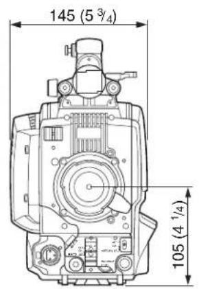
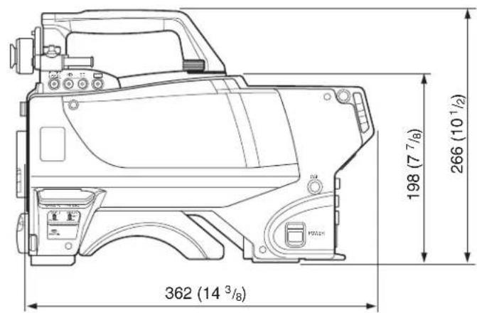
Related equipment
HDFX100 HD Triax CCU Adaptor
HDCU1000/1500 HD Camera Control Unit
MSU-900/950 Master Setup Unit
RCP-700/900-series Remote Control Panel
VCS-700 Video Selector
CNU-700 Camera Command Network Unit
Design and specifications are subject to change without notice.
HDC1400
General
Power requirements 240 V AC, 1.4 A (max.)
180 V DC, 1.0 A (max.)
12 V DC, 7 A (max.)
Operating temperature
-20^ to +45^ (-4^ to +113^)
Storage temperature -20^ to +60^ ( -4^ to +140^ )
Mass Approx. 4.5 kg (9 lb 15 oz) (camera
head only)
Imager
Imager 2/3-type Progressive Scan CCD
Method 3-CCD, RGB
Effective resolution 1920 (horizontal) × 1080 (vertical)
Electrical characteristics
Sensitivity f10.0 with 1080/59.94i
f11.0 with 1080/50i
(at 2000 lx with 89.9% reflectivity)
Image S/N Typical -54 dB/-62 dB (NS MAX)
Horizontal resolution
1000 TV lines (at center of screen)
5% or higher modulation
Registration 0.02% for total area (not including
lens distortion)
Geometric distortion Negligible (not including lens
distortion)
Optical system specifications
Spectral system F1.4 prism
Built-in optical filters1: clear
2: 1/4 ND
3: 1/16 ND
4: 1/64 ND
5: cross
Input/output connectors
CCU Optical/electrical multi-connector
(1)
LENS 12-pin (1)
VF 20-pin (1)
MIC 1 IN XLR 3-pin, female (1)
AUDIO IN CH1, CH2
XLR 3-pin, female (1 each)
For MIC: -60 dBu (may be selected
to -20 dBu by menu or
HDCU1000/1500 operations),
balanced
For LINE: 0 dBu, balanced
INTERCOM1, INTERCOM2
XLR 5-pin, female (1 each)
EARPHONE Stereo minijack (1)
DC IN XLR 4-pin (1), 10.5 to 17 V DC
DC OUT 4-pin (1), 10.5 to 17 V DC, 1.5 A
maximum
It may be limited depending on the
load and input conditions.
Dimensions
Unit: mm (inches)
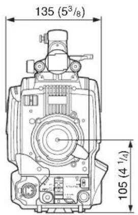
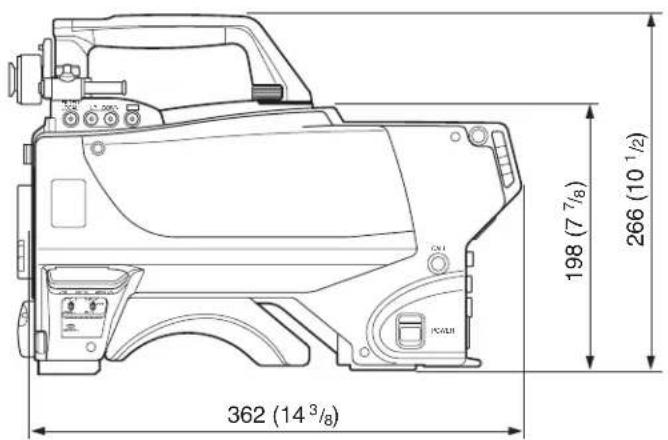
SDI BNC type (1)
TEST OUT BNC type (1)
PROMPTER BNC type (1), 1 Vp-p, 75 ohms
RET CTRL 6-pin (1)
REMOTE 8-pin (1)
TRACKER 10-pin (1)
CRANE 12-pin (1)
Supplied accessories
Operation manual (1)
Switch label 1, 2 (1 each)
Optional accessories
HDVF-20A HD Electronic Viewfinder (2-type, monochrome)
HDVF-C35W HD Electronic Viewfinder (3.5-type, color)
HDVF-C730W HD Electronic Viewfinder (6.3-type, color)
HDVF-C950W HD Electronic Viewfinder (9-type, color)
HDLA1500/1505 Large Lens Adaptor
HDLA1507 Large Viewfinder Adaptor
CAC-12 Microphone Holder
CAC-6 Return Video Selector
BKW-401 Viewfinder Rotation Bracket
HKC-DF14 Dual Optical Filter Unit
VCT-14 Tripod Adaptor
Memory Stick
Low-repulsion Shoulder Pad A-8286-346-A
Related equipment
HDCU1000/1500 HD Camera Control Unit
MSU-900/950 Master Setup Unit
RCP-700/900-series Remote Control Panel
VCS-700 Video Selector
CNU-700 Camera Command Network Unit
For the customers in the U.S.A., Canada, Europe, Australia, and New Zealand
Connectors for optical/electric composite cables:
- L E M®DUW.3K.93C.TLCC96 (to the “CAMERA” connector on HDCU)
- L E Ms BUW.3K.93C.TLMC96 (to the "HDCU" connector on CAMERA)
Caution on the optical/electric composite cable:
For connection between the HD camera control unit and a camera, be sure to use an optical/electric signal composite cable with the connectors specified in this manual in order to comply with the limit for EMC regulations.
Design and specifications are subject to change without notice.
HDC1450
General
Power requirements 180 V DC, 1.0 A (max.)
12 V DC, 7 A (max.)
Operating temperature
-20^ to +45^ (-4^ to +113^)
Storage temperature -20^ to +60^ (-4^ to +140^)
Mass Approx. 4.9 kg (10 lb 13 oz) (camera
head only)
Imager
Imager 2/3-type Progressive Scan CCD
Method 3-CCD, RGB
Effective resolution 1920 (horizontal) × 1080 (vertical)
Electrical characteristics
Sensitivity f10.0 with 1080/59.94i
f11.0 with 1080/50i
(at 2000 lx with 89.9% reflectivity)
Image S/N Typical -54 dB/-62 dB (NS MAX)
Horizontal resolution
1000 TV lines (at center of screen)
5% or higher modulation
Registration 0.02% for total area (not including lens distortion) Geometric distortion Negligible (not including lens distortion)
Optical system specifications
Spectral system F1.4 prism
Built-in optical filters1: clear
2: 1/4 ND
3: 1/16 ND
4: 1/64 ND
5: cross
Input/output connectors
HDCU/HDFX Triax connector (1)
LENS 12-pin (1)
VF 20-pin (1)
MIC 1 IN XLR 3-pin, female (1)
AUDIO IN CH1, CH2
XLR 3-pin, female (1 each)
For MIC: -60 dBu (may be selected to -20 dBu by menu or
HDCU1000/1500 operations), balanced
For LINE: 0 dBu, balanced
INTERCOM1, INTERCOM2
XLR 5-pin, female (1 each)
EARPHONE Stereo minijack (1)
DC IN XLR 4-pin (1), 10.5 to 17 V DC
DC OUT 4-pin (1), 10.5 to 17 V DC, 1.5 A
maximum
It may be limited depending on the
load and input conditions.
SDI BNC type (1)
TEST OUT BNC type (1)
PROMPTER BNC type (1), 1 Vp-p, 75 ohms
RET CTRL 6-pin (1)
REMOTE 8-pin (1)
TRACKER 10-pin (1)
CRANE 12-pin (1)
Supplied accessories
Operation manual (1)
Switch label 1, 2 (1 each)
Optional accessories
HDVF-20A HD Electronic Viewfinder (2-type, monochrome)
HDVF-C35W HD Electronic Viewfinder (3.5-type, color)
HDVF-C730W HD Electronic Viewfinder (6.3-type, color)
HDVF-C950W HD Electronic Viewfinder (9-type, color)
HDLA1500/1505 Large Lens Adaptor
HDLA1507 Large Viewfinder Adaptor
CAC-12 Microphone Holder
CAC-6 Return Video Selector
BKW-401 Viewfinder Rotation Bracket
HKC-DF14 Dual Optical Filter Unit
VCT-14 Tripod Adaptor
Memory Stick
Low-repulsion Shoulder Pad A-8286-346-A
Related equipment
HDFX100 HD Triax CCU Adaptor
HDCU1000/1500 HD Camera Control Unit
MSU-900/950 Master Setup Unit
RCP-700/900-series Remote Control Panel
VCS-700 Video Selector
CNU-700 Camera Command Network Unit
Design and specifications are subject to change without notice.
Dimensions
Unit: mm (inches)
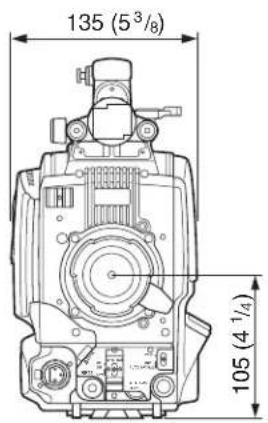
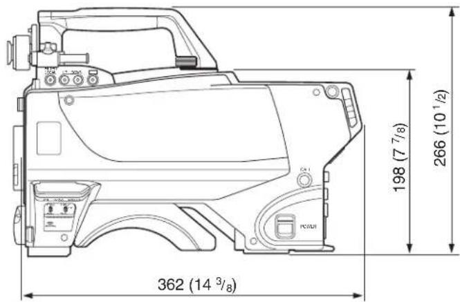
Note
Always verify that the unit is operating properly before use. SONY WILL NOT BE LIABLE FOR DAMAGES OF ANY KIND INCLUDING, BUT NOT LIMITED TO, COMPENSATION OR REIMBURSEMENT ON ACCOUNT OF THE LOSS OF PRESENT OR PROSPECTIVE PROFITS DUE TO FAILURE OF THIS UNIT, EITHER DURING THE WARRANTY PERIOD OR AFTER EXPIRATION OF THE WARRANTY, OR FOR ANY OTHER REASON WHATSOEVER.
The material contained in this manual consists of information that is the property of Sony Corporation and is intended solely for use by the purchasers of the equipment described in this manual.
Sony Corporation expressly prohibits the duplication of any portion of this manual or the use thereof for any purpose other than the operation or maintenance of the equipment described in this manual without the express written permission of Sony Corporation.
For Customer in China
HDC1400 (JN3/JN4/CE/E33)
HDC1450 (UC/CE)
HDC1500 (SYL/JN4/CE/E33)
HDC1550 (UC/CE)
HDC1600 (J)
3-868-749-09(1)
Sony Corporation
http://www.sony.net/

この説明書は、再生紙を使用しています。
Printed on recycled paper.
Printed in Japan
2008.05.13
© 2005
- 安全のために
- ご注意
- AVERTISSEMENT
- For the customers in the U.S.A.
- Laser diode properties
- CAUTION
- For the customers in Europe
- Locations and Functions of Parts....67
- Preparations....76
- Adjustments and Settings for Recording....80
- Setting the Camera Outputs ....84
- Viewfinder Screen Status Display....87
- Menu Operations ....88
- Menu List....94
- Using a "Memory Stick"....109
- Specifications ....111
- Overview
- Features
- High picture quality and high performance
- Multiple formats
- Newly designed integrated unit with low center of gravity
- Swing handle
- Position-adjustable shoulder pad
- Function-assignable switches
- Memory Stick 1) operation
- Various color-reproduction functions
- Selection of the gamma table
- Multimatrix color correction
- Knee saturation
- Low key saturation
- Versatile detail control functions
- Skin-tone detail function
- Detail boost-frequency control
- H/V ratio control
- White/black limiter
- Easy menu-based setting
- Wide variety of viewfinder display options
- Optical digital transmission (HDC1500/1400)
- High-resolution 2-type monochrome and 3.5-type color multiformat viewfinders (optional)
- Prevention of electrical shock
- System Configuration
- Note
- Connection example 3
- Maximum cable run with Triax cable
- Notes
- Precautions
- Note on laser beams
- Do not subject to severe shocks
- When finished using
- Operation and storage environment
- Condensation
- Phenomena Specific to CCD Image Sensors
- White flecks
- Smear
- Aliasing
- Locations and Functions of Parts
- Accessory Attachments
- ⑩Tripod mount
- ⑪Shoulder pad
- Controls and Connectors
- Front right
- ①INCOM (intercom 1) button
- ②RET 1 (return video 1) button
- ③ Assignable switch
- ④Filter select buttons
- HDC1500/1550
- HDC1400/1450
- ⑥ AUTO W/B BAL (white and black balance automatic adjustment) switch
- ⑦GAIN switch
- ⑧ OUTPUT (output signal selection)/AUTO KNEE switch
- ⑨WHITE BAL (white balance memory selection) switch
- ⑩DISPLAY switch
- ⑪ CANCEL/STATUS switch
- ⑫Memory Stick section
- MENU SEL (menu select) knob/ENTER button (rotary encoder)
- Front left
- ①RET 1 (return video 1) button
- ②MIC 1 IN (microphone 1 input) connector (XLR 3-pin)
- ③MIC (microphone) power switch
- ④SHUTTER switch
- ⑤ INTERCOM LEVEL control
- ⑥RET 2 (return video 2) button
- Rear
- ①CAMERA POWER switch
- ②Tally lamp and switch
- ③CCU (Camera Control Unit) connector (optical/electrical multi-connector) (HDC1500/1400)
- ③HDCU/HDFX (HD Triax CCU) connector (Triax connector) (HDC1550/1450)
- ④ SDI 1 (serial digital interface 1) connector (BNC type) (HDC1500 only)
- ⑤PROMPTER2 connector (BNC type) (HDC1500 only)
- ⑥ CALL button
- Operation panel
- ① INTERCOM1 and INTERCOM2 controls and switches
- PGM1 (program 1) control
- PGM2 (program 2) control
- LEVEL/MIC switch
- INCOM level control
- Line select switch
- ②RET 1 (return video 1) button and select switch
- ③RET 2 (return video 2) button and select switch
- LIGHT switch
- ENG (engineer line) control:
- PROD (producer line) control
- TRACKER control
- MIC LINE1 (intercom microphone line 1) switch
- MIC LINE2 (intercom microphone line 2) switch
- LEVEL switch
- ④LIGHT switch
- Connector panel
- ⑨PROMPTER (prompter signal output) connector (BNC type) (HDC1400/1450)
- ⑩TEST OUT connector (BNC type)
- ⑪SDI 2 (serial digital interface 2) connector (BNC type) (HDC1500)
- ⑪ SDI (serial digital interface) connector (BNC type) (HDC1550/1400/1450)
- AUDIO IN CH1 and CH2 connectors (XLR 3-pin) and switches
- CH1 audio input select switch
- CH2 audio input select switch
- Microphone power switches
- Preparations
- Attaching a Lens
- Adjusting the Flange Focal Length
- Attaching a Viewfinder
- Example: Attaching a HDVF-20A/C35W Viewfinder
- Attaching procedure
- Adjusting the viewfinder position
- To adjust the position to the left or right
- To adjust the position forward or backward
- To detach the viewfinder
- Keeping the viewfinder from hitting your leg
- Attaching procedure of the BKW-401
- Adjusting the Shoulder Pad Position
- Adjusting procedure
- Mounting the Camera to a Tripod
- Mounting procedure
- To remove the camera from the tripod adaptor
- Adjustments and Settings for Recording
- Adjusting the Black Balance and White Balance
- Black balance adjustment
- White balance adjustment
- About the viewfinder screen
- Adjusting the black balance
- Procedure for adjusting the black balance
- When automatic black balance adjustment fails
- About black balance memory
- Adjusting the white balance
- Procedure for adjusting the white balance
- To select the ND filter
- To select the CC filter
- When automatic white balance adjustment fails
- When there is no time to adjust the white balance
- About white balance memory
- Setting the Electronic Shutter
- About the shutter modes
- Selecting the shutter mode and speed
- Setting the shutter mode, and shutter speed in standard mode
- Setting the Camera Outputs
- Outputting the signal being shot (camera picture)
- Constantly outputting a return video
- Outputting the same image as that on the viewfinder
- Outputting via Dual Link (HDC1500 only)
- Viewfinder Screen Status Display
- When the DISPLAY switch is set to ON
- ①Zoom position
- ② Lens extender
- ③Digital extender (HDC1500/1550 only)
- ④ TALK indication
- 55600K mode
- 6Filter
- ⑦ White balance memory
- ⑧Gain value
- ⑨ Focus position
- ⑩Battery voltage
- ⑪F value
- ⑫Shutter/EVS
- When you press the CANCEL/STATUS switch toward STATUS
- ① Assignable switch indication
- ②Format indication
- ③‘!’ indication area
- ④ Optical level indications (HDC1500/1400 only)
- Menu Operations
- Starting Menu Operations
- To display a menu page
- To display the TOP MENU screen
- To disable the "TOP" indication
- Available menus
- USER menu
- USER MENU CUSTOMIZE menu
- ALL menu
- OPERATION menu
- PAINT menu
- MAINTENANCE menu
- FILE menu
- DIAGNOSIS menu
- To select a menu on the TOP MENU screen
- Selecting Pages
- When selecting a page from a CONTENTS page
- To change the displayed page
- To return to the TOP MENU screen
- Setting the Menu Items
- To reset a changed value
- To interrupt settings
- To specify a character string
- To end menu operations
- Editing the USER Menu
- Creating a new page
- To delete items from a page
- To change the order of items on a page
- To insert a blank line
- Adding/deleting/replacing pages
- To add a page
- To cancel addition of a page
- To delete a page
- To move a page
- Menu List
- Using a “Memory Stick”
- Inserting a "Memory Stick"
- Access lamp
- What is "Memory Stick"?
- Types of "Memory Stick"
- "Memory Stick-R"
- "Memory Stick"
- "MagicGate Memory Stick"
- "Memory Stick-ROM"
- "Memory Stick PRO"
- Usable types of "Memory Stick"
- Note on data read/write speed
- What is MagicGate?
- About a "Memory Stick"
- Specifications
- HDC1500
- General
- Imager
- Electrical characteristics
- Optical system specifications
- Input/output connectors
- Supplied accessories
- Optional accessories
- Related equipment
- For the customers in the U.S.A., Canada, Europe, Australia, and New Zealand
- Caution on the optical/electric composite cable:
- HDC1550
- HDC1400
- HDC1450
- Sony Corporation
Brand : SONY
Model : HDC-1450
Category : Camcorder