
RAV4 EV (2013) - Automotive TOYOTA - Free user manual and instructions
Find the device manual for free RAV4 EV (2013) TOYOTA in PDF.


| Product Type | All-Electric SUV |
| Brand | Toyota |
| Model | RAV4 EV (2013) |
| Battery Capacity | 41.8 kWh |
| Electric Range (EPA) | 76 miles (122 km) |
| Charging Time (120V) | Approx. 18 hours (full charge) |
| Charging Time (240V) | Approx. 6 hours (full charge) |
| DC Fast Charging (CHAdeMO) | Up to 50 kW |
| Motor | AC induction, 115 kW (154 hp) |
| Torque | 273 lb-ft (370 Nm) |
| Drivetrain | Front-wheel drive |
| Dimensions (L x W x H) | 180.9 x 71.5 x 65.5 in (4595 x 1816 x 1664 mm) |
| Curb Weight | 4,030 lbs (1,828 kg) |
| Seating Capacity | 5 passengers |
| Cargo Volume (rear seats up) | 38.4 cu ft (1,087 L) |
| Safety Features | ABS, traction control, stability control, airbags |
| Maintenance | No oil changes; tire rotation, brake checks, cabin filter replacement |
| Warranty (Basic) | 3 years / 36,000 miles |
| Warranty (Battery) | 8 years / 100,000 miles |
Frequently Asked Questions - RAV4 EV (2013) TOYOTA
User questions about RAV4 EV (2013) TOYOTA
0 question about this device. Answer the ones you know or ask your own.
Ask a new question about this device
Download the instructions for your Automotive in PDF format for free! Find your manual RAV4 EV (2013) - TOYOTA and take your electronic device back in hand. On this page are published all the documents necessary for the use of your device. RAV4 EV (2013) by TOYOTA.
USER MANUAL RAV4 EV (2013) TOYOTA
| 1 | Before driving | Information on the EV system, adjusting and operating features such as door locks, mirrors, and steering column. |
| 2 | When driving | Driving, stopping and safe-driving information. |
| 3 | Interior features | Air conditioning, as well as other interior features for a comfortable driving experience. |
| 4 | Maintenance and care | Cleaning and protecting your vehicle, performing do-it-yourself maintenance, and maintenance information. |
| 5 | When trouble arises | What to do if the vehicle needs to be towed, gets a flat tire, or is involved in an accident. |
| 6 | Vehicle specifications | Detailed vehicle information. |
| 7 | For owners | Reporting safety defects for U.S. owners |
| Index | Alphabetical listing of information contained in this manual. |
1 Before driving
1-1. EV system
Characteristics of the EV (Electric Vehicle) system.... 26
EV (Electric Vehicle) system precautions .... 32
Energy monitor/consumption screen.... 38
EV (Electric Vehicle) driving tips.... 41
1-2. Navigation system screen operations
Navigation system screen operations 44
1-3. Charging
Charging equipment...... 46
Power sources that can be used 50
Charging and pre-climate (Remote Climate Control) procedures.... 53
When normal charging cannot be carried out ..... 88
Inspecting the charging cable 92
1-4. Key information
Keys 94
1-5. Opening, closing and locking the doors
Smart key system.... 96
Wireless remote control..... 108
Side doors 110
Back door 113
1-6. Adjustable components (seats, mirrors, steering wheel)
Front seats.... 118
Rear seats 121
Head restraints 127
Seat belts.... 131
Steering wheel.... 140
Anti-glare inside rear view mirror.... 141
Outside rear view mirrors ... 143
1-7. Opening and closing the windows
Power windows.... 146
1-8. Theft deterrent system
Immobilizer system...... 149
Theft prevention labels ..... 151
1-9. Safety information
Correct driving posture ..... 152
SRS airbags 154
Front passenger occupant classification system...... 166
Child restraint systems ..... 172
Installing child restraints ..... 176
2 When driving
2-1. Driving procedures
Driving the vehicle.... 190
Power switch...... 200
Transmission...... 206
Turn signal lever 215
Parking brake.... 216
Horn 217
2-2. Instrument cluster
Gauges and meters ..... 218
Indicators and warning lights 223
Multi-information display ..... 227
2-3. Operating the lights and wipers
Headlight switch...... 234
Windshield wipers and washer 238
Rear window wiper and washer 241
2-4. Using other driving systems
Cruise control.... 243
Rear view monitor system 247
Driving assist systems ..... 251
Hill-start assist control...... 256
2-5. Driving information
Utility vehicle precautions.... 258
Cargo and luggage...... 263
Vehicle load limits.... 267
Winter driving tips.... 268
Trailer towing.... 273
Dinghy towing.... 274
3 Interior features
3-1. Using the air conditioning system and defogger
Automatic air conditioning system...... 276
Rear window and outside rear view mirror defoggers 292
3-2. Using the interior lights
Interior lights list 293
- Personal/interior light main switch 294
• Personal/interior lights..... 294
- Interior light 295
- Luggage compartment light.... 295
3-3. Using the storage features
List of storage features..... 296
- Glove box.... 297
- Console box 298
• Cup holders...... 299
- Bottle holders 300
- Auxiliary boxes...... 302
3-4. Other interior features
Sun visors 304
Vanity mirrors.... 305
Power outlets 306
Seat heaters.... 310
Armrest.... 313
Coat hooks.... 314
Assist grips.... 315
Floor mat.... 316
Luggage compartment features...... 317
Garage door opener...... 320
Safety Connect.... 326
4 Maintenance and care
4-1. Maintenance and care
Cleaning and protecting the vehicle exterior...... 334
Cleaning and protecting the vehicle interior...... 337
4-2. Maintenance
Maintenance requirements.... 340
General maintenance...... 342
4-3. Do-it-yourself maintenance
Do-it-yourself service precautions.... 346
Hood.... 349
Positioning a floor jack...... 351
Motor compartment 355
Tires.... 366
Tire inflation pressure...... 374
Wheels.... 378
Air conditioning filter ..... 381
Electronic key battery ..... 383
Checking and replacing fuses.... 385
Headlight aim.... 398
Light bulbs 400
5 When trouble arises
5-1. Essential information
Emergency flashers...... 412
If your vehicle needs to be towed.... 413
If you think something is wrong.... 416
5-2. Steps to take in an emergency
If a warning light turns on or a warning buzzer sounds... 417
If a warning message is displayed.... 427
If you have a flat tire...... 447
If the EV (Electric Vehicle) system will not start ..... 465
If you lose your keys ..... 467
If the electronic key does not operate properly...... 468
If the vehicle 12-volt battery is discharged...... 470
If your vehicle overheats..... 475
If the vehicle becomes stuck 477
If your vehicle has to be stopped in an emergency.... 479
6 Vehicle specifications
6-1. Specifications
Maintenance data (fluid capacity, etc.)...... 482
Tire information...... 489
6-2. Customization
Customizable features ..... 500
6-3. Initialization
Items to initialize 503
7 For owners
Reporting safety defects for U.S. owners 506
Index
Abbreviation list...... 508
Alphabetical index 509
What to do if... 518
1
2
3
4
5
6
7
Pictorial index
Exterior
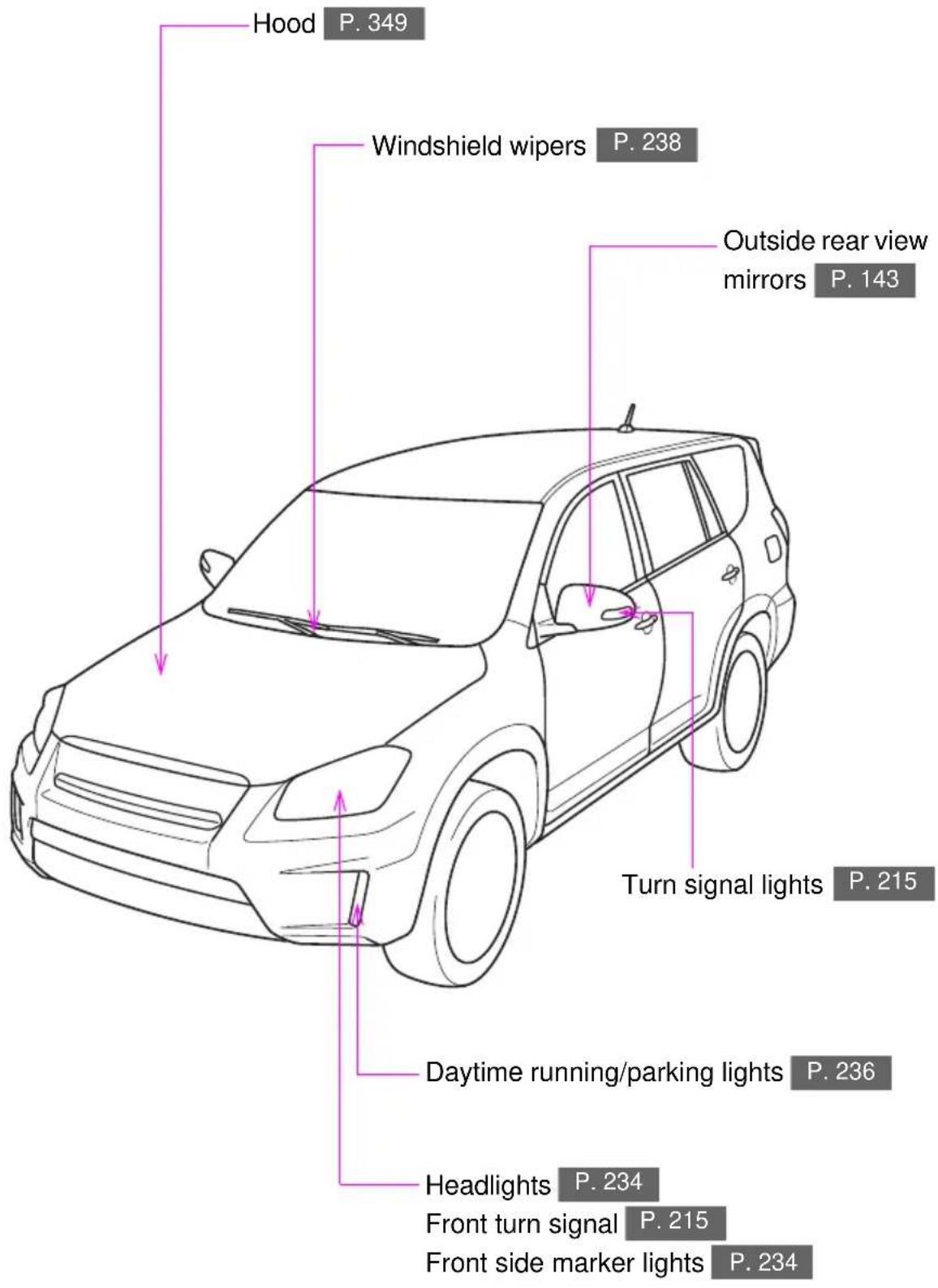
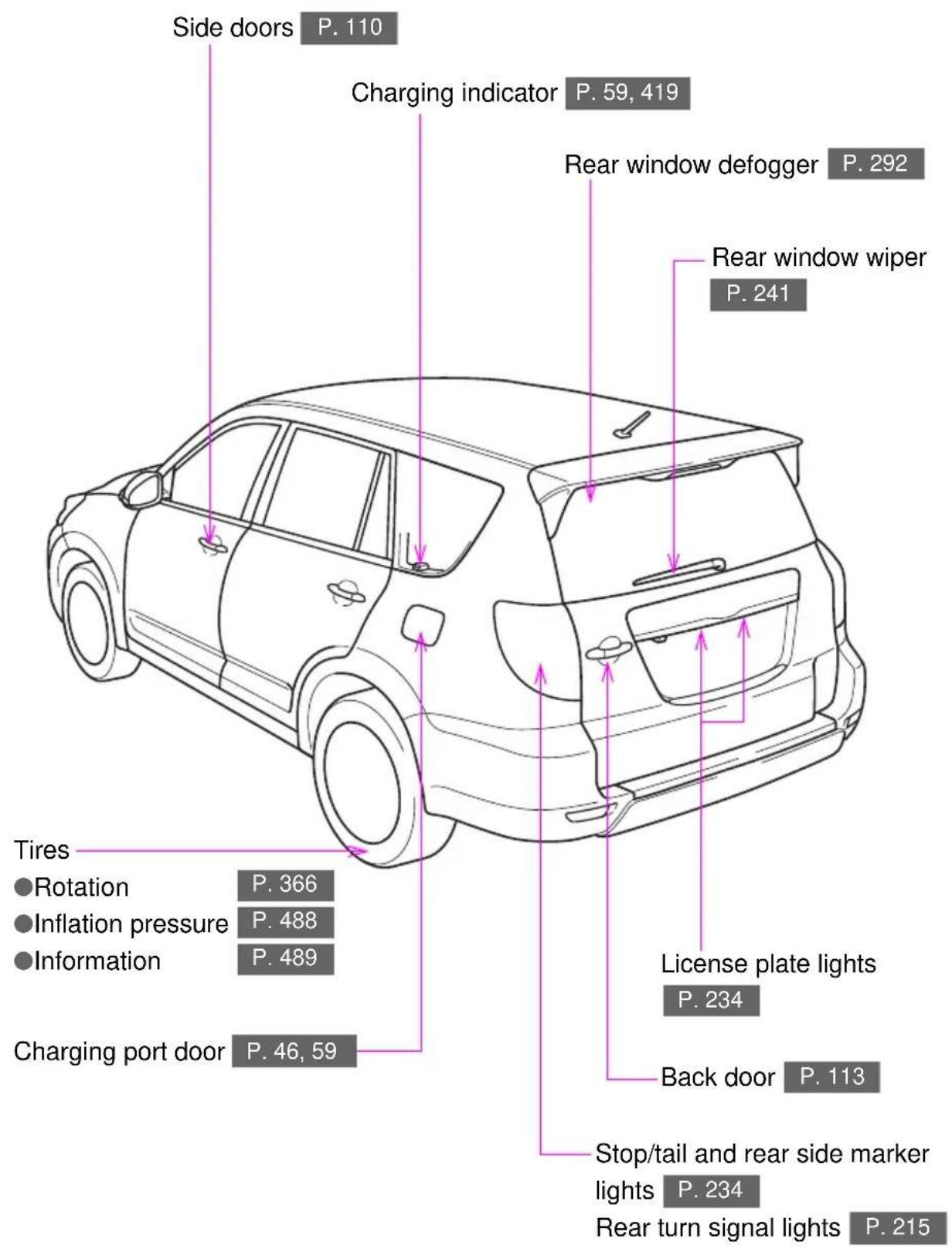
Pictorial index
Interior
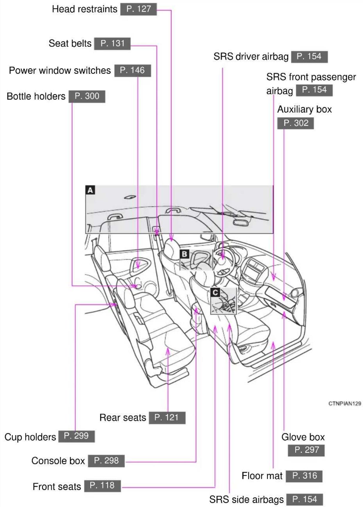
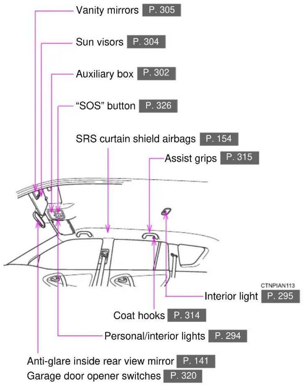
A
B
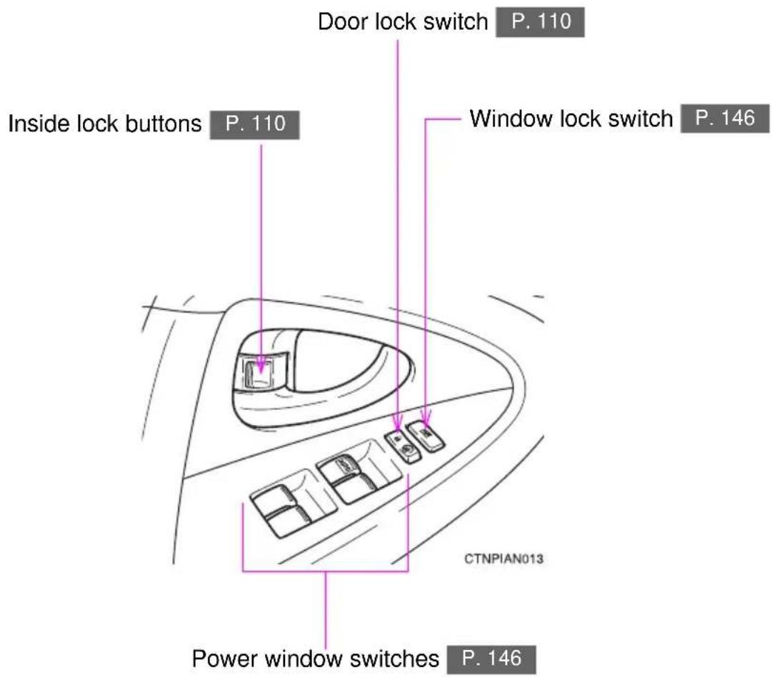
C
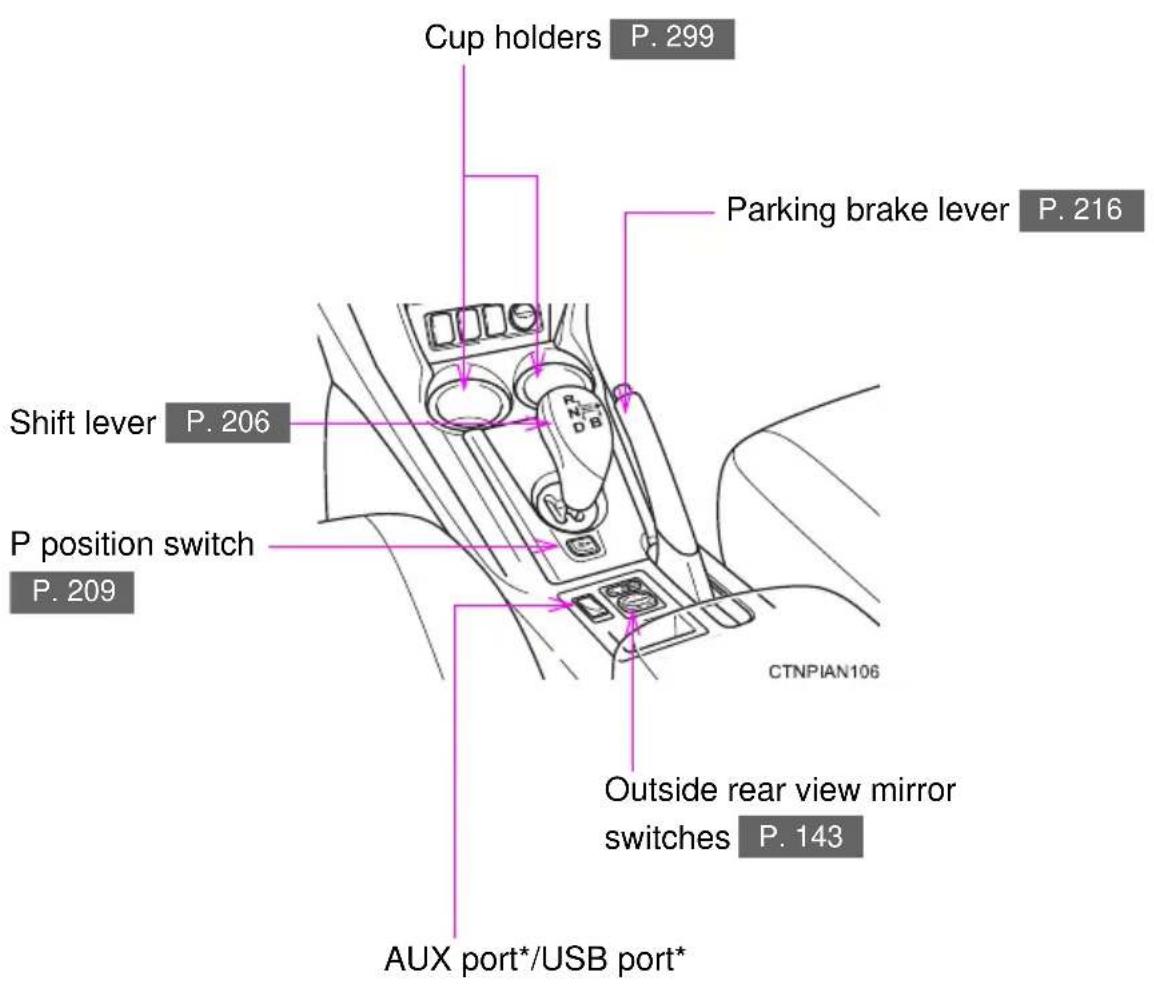
*: Refer to "Navigation System Owner's Manual".
Pictorial index
Instrument panel
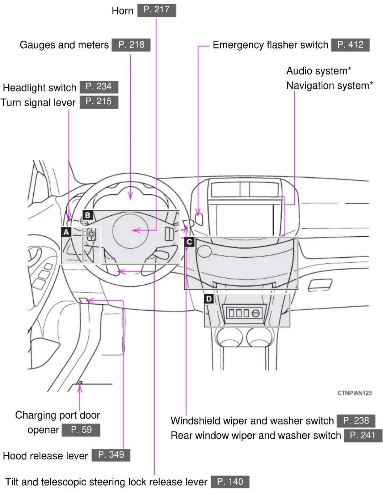
A
Instrument panel light control dial P. 219
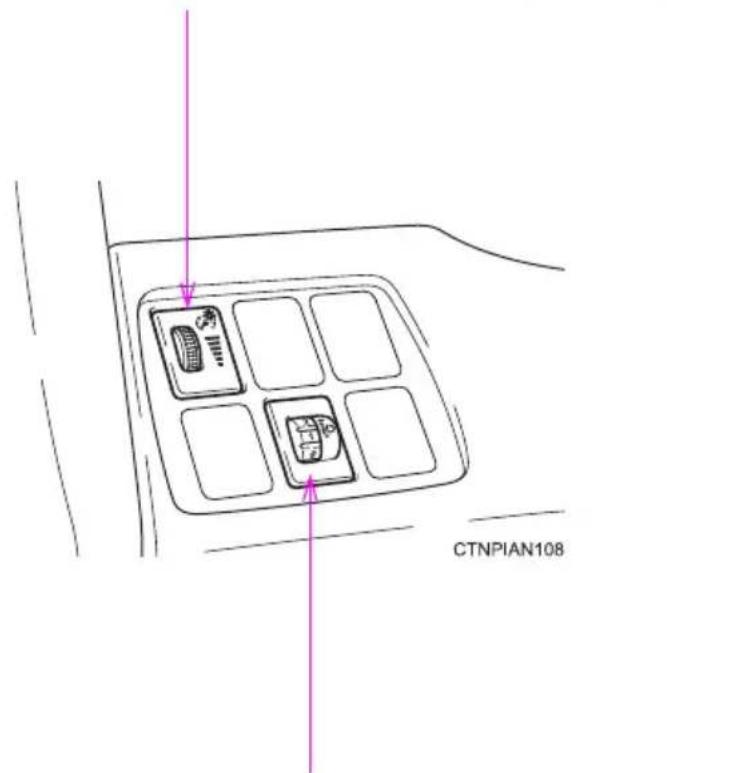
Manual headlight leveling dial
P.235
*: Refer to "Navigation System Owner's Manual".
B
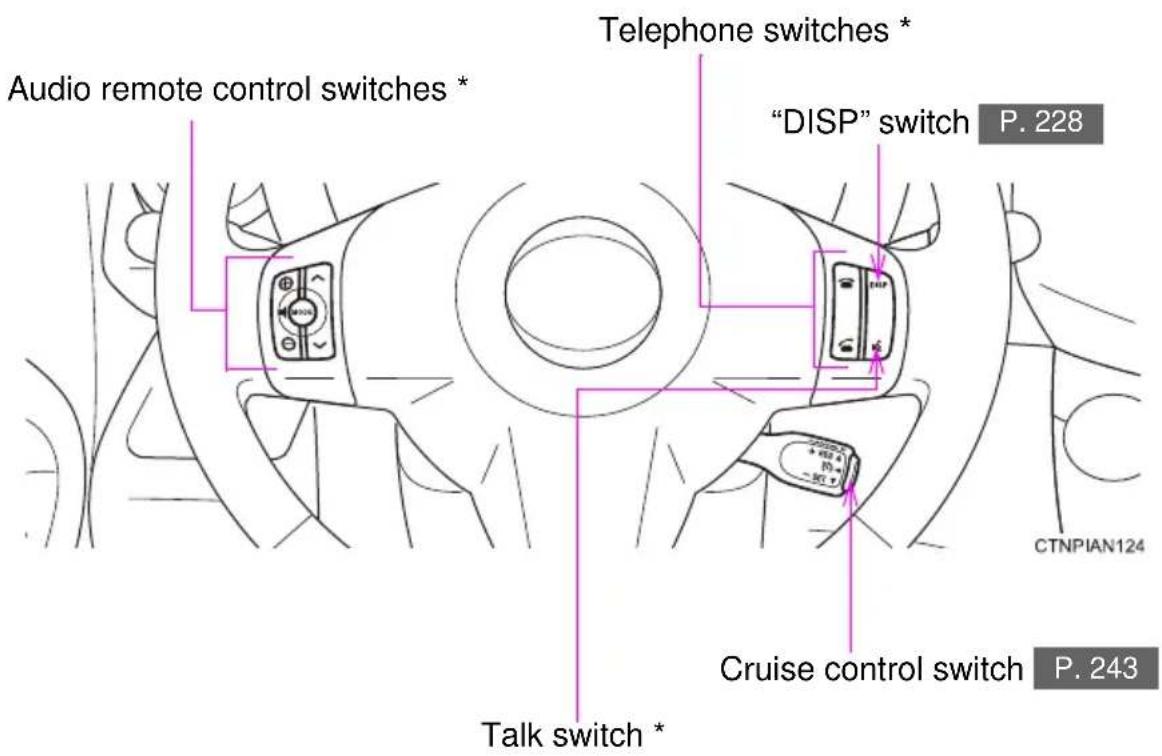
C
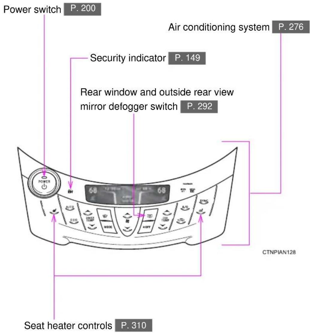
*: Refer to "Navigation System Owner's Manual".
Pictorial index
Instrument panel
D
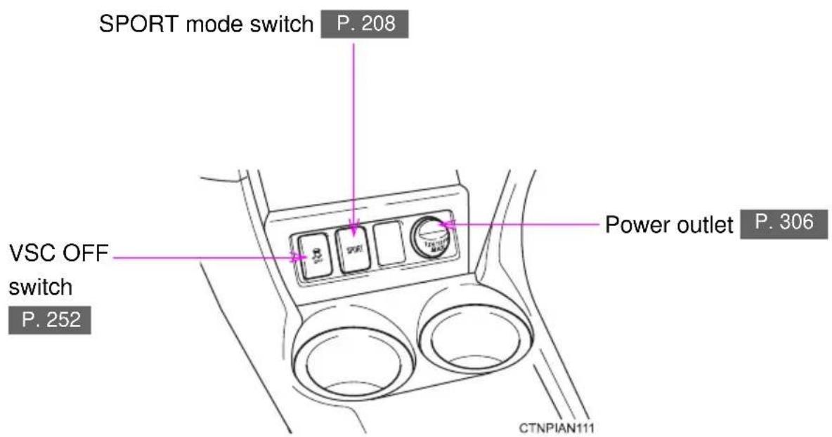
Pictorial index
Luggage compartment
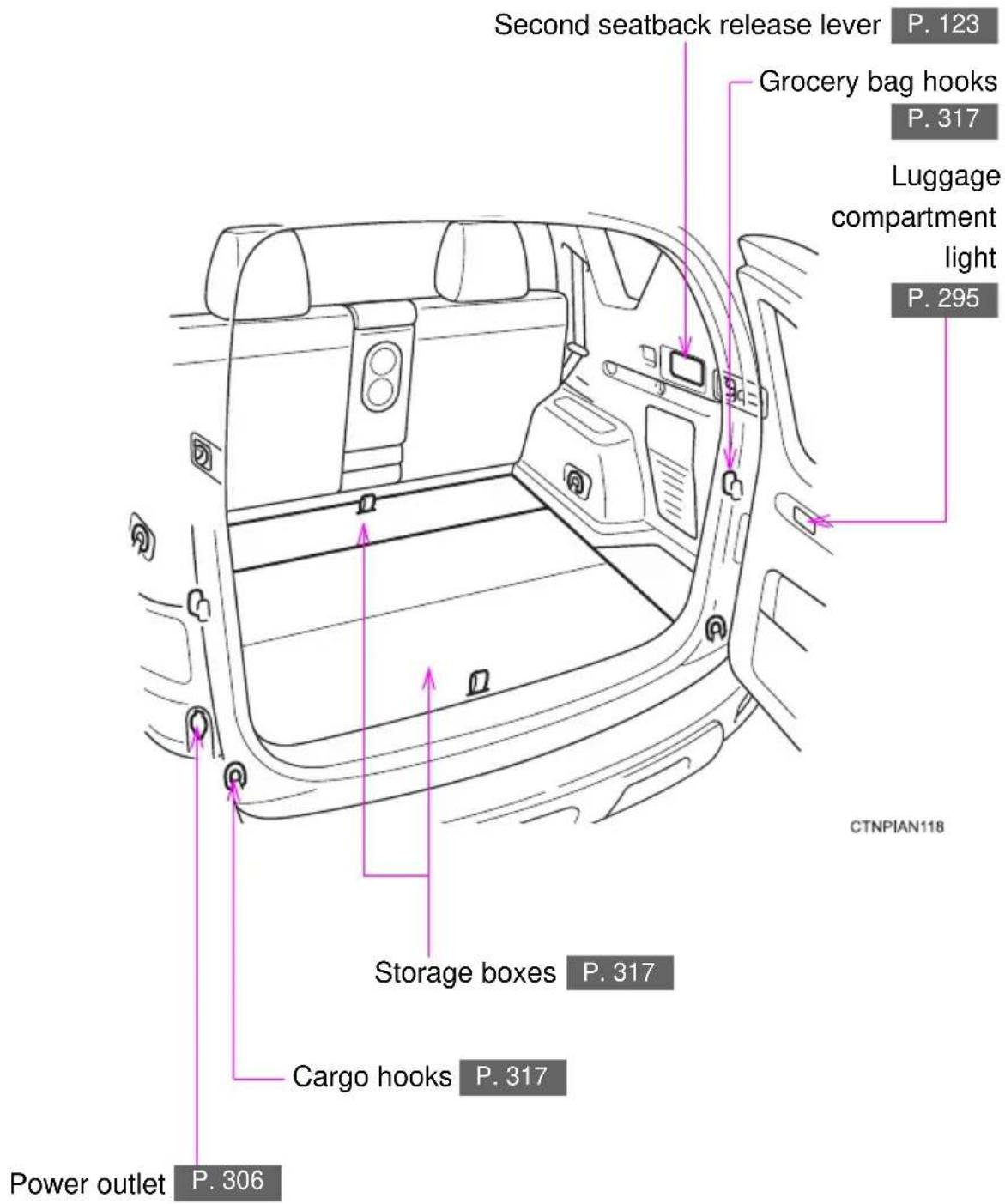
For your information
Main Owner's Manual
Please note that this manual covers all models and all equipment, including options. Therefore, you may find some explanations for equipment not installed on your vehicle.
All specifications provided in this manual are current at the time of printing. However, because of the Toyota policy of continual product improvement, we reserve the right to make changes at any time without notice.
Depending on specifications, the vehicle shown in the illustrations may differ from your vehicle in terms of equipment.
Accessories, spare parts and modification of your Toyota
A wide variety of non-genuine spare parts and accessories for Toyota vehicles are currently available on the market. You should know that these parts are not covered by Toyota warranty and that Toyota is not responsible for their performance, repair, or replacement, or for any damage they may cause to, or adverse effect they may have on, your Toyota vehicle.
This vehicle should not be modified with non-genuine Toyota products. Modification with non-genuine Toyota products may affect performance, safety or durability, and may even violate governmental regulations. In addition, damage or performance problems resulting from the modification may not be covered under warranty.
Installation of a mobile two-way radio system
The installation of a mobile two-way radio system in your vehicle could affect electronic systems such as:
●Cruise control system
●Anti-lock brake system
●SRS airbag system
- Seat belt pretensioner system
Be sure to check with your Toyota dealer for precautionary measures or special instructions regarding installation of a mobile two-way radio system.
Vehicle data recordings
Your Toyota is equipped with several sophisticated computers that will record certain data, such as:
• Electric motor speed (traction motor speed)
- Accelerator status
- Brake status
- Vehicle speed
- Shift position
- Traction battery status
The recorded data varies according to the vehicle grade level and options with which it is equipped. Furthermore, these computers do not record conversations, sounds or pictures.
●Data usage
Toyota may use the data recorded in these computers to diagnose malfunctions, conduct research and development, and improve quality.
Toyota will not disclose the recorded data to a third party except:
- With the consent of the vehicle owner or with the consent of the lessee if the vehicle is leased
- In response to an official request by the police, a court of law or a government agency
- For use by Toyota in a law suit
- For research purposes where the data is not tied to a specific vehicle or vehicle owner
●Usage of data collected through Safety Connect
If your Toyota has Safety Connect and if you have subscribed to those services, please refer to the Safety Connect Telematics Subscription Service Agreement for information on data collected and its usage.
Event data recorder
This vehicle is equipped with an event data recorder (EDR). The main purpose of an EDR is to record, in certain crash or near crash-like situations, such as an air bag deployment or hitting a road obstacle, data that will assist in understanding how a vehicle's systems performed. The EDR is designed to record data related to vehicle dynamics and safety systems for a short period of time, typically 30 seconds or less.
The EDR in this vehicle is designed to record such data as:
- How various systems in your vehicle were operating;
- Whether or not the driver and passenger safety belts were buckled/fas-stened;
- How far (if at all) the driver was depressing the accelerator and/or brake pedal; and,
• How fast the vehicle was traveling.
These data can help provide a better understanding of the circumstances in which crashes and injuries occur.
NOTE: EDR data are recorded by your vehicle only if a non-trivial crash situation occurs; no data are recorded by the EDR under normal driving conditions and no personal data (e.g., name, gender, age, and crash location) are recorded. However, other parties, such as law enforcement, could combine the EDR data with the type of personally identifying data routinely acquired during a crash investigation.
To read data recorded by an EDR, special equipment is required, and access to the vehicle or the EDR is needed. In addition to the vehicle manufacturer, other parties, such as law enforcement, that have the special equipment, can read the information if they have access to the vehicle or the EDR.
●Disclosure of the EDR data
Toyota will not disclose the data recorded in an EDR to a third party except when:
- An agreement from the vehicle's owner (or the lessee for a leased vehicle) is obtained
- In response to an official request by the police, a court of law or a government agency
-
For use by Toyota in a law suit
However, if necessary, Toyota may: -
Use the data for research on vehicle safety performance
- Disclose the data to a third party for research purposes without disclosing information about the specific vehicle or vehicle owner
Scrapping of your Toyota
The SRS airbag and seat belt pretensioner devices in your Toyota contain explosive chemicals. If the vehicle is scrapped with the airbags and seat belt pretensioners left as they are, this may cause an accident such as fire. Be sure to have the systems of the SRS airbag and seat belt pretensioner removed and disposed of by a qualified service shop or by your Toyota dealer before you scrap your vehicle. Additionally, the lithium-ion battery (traction battery) may cause an accident such as a fire if it is not removed prior to scrapping. The lithium-ion battery can be disposed of at your Toyota dealer.
Perchlorate Material
Special handling may apply, See www.dtsc.ca.gov/hazardouswaste/perchlorate.
Your vehicle has components that may contain perchlorate. These components may include airbag, seat belt pretensioners, and wireless remote control batteries.

CAUTION
■General precautions while driving
Driving under the influence: Never drive your vehicle when under the influence of alcohol or drugs that have impaired your ability to operate your vehicle. Alcohol and certain drugs delay reaction time, impair judgment and reduce coordination, which could lead to an accident that could result in death or serious injury.
Defensive driving: Always drive defensively. Anticipate mistakes that other drivers or pedestrians might make and be ready to avoid accidents.
Driver distraction: Always give your full attention to driving. Anything that distracts the driver, such as adjusting controls, talking on a cellular phone or reading can result in a collision with resulting death or serious injury to you, your occupants or others.
■General precaution regarding children's safety
Never leave children unattended in the vehicle, and never allow children to have or use the key.
Children may be able to start the vehicle or shift the vehicle into neutral. There is also a danger that children may injure themselves by playing with the windows, the moon roof, or other features of the vehicle. In addition, heat build-up or extremely cold temperatures inside the vehicle can be fatal to children.
■Traction battery
Never resell, hand over or modify the traction battery. To prevent accidents, traction batteries that have been removed from a disposed vehicle are collected through Toyota dealers. Do not dispose of the battery yourself.
Unless the battery is properly collected, the following may occur, resulting in death or serious injury:
●The traction battery may be illegally disposed of or dumped, and someone may touch a high voltage part, resulting in an electric shock.
●The traction battery is intended to be used exclusively with your EV. If the traction battery is used outside of your vehicle or modified in any way, accidents such as electric shock, heat generation, smoke generation, an explosion and electrolyte leakage may occur.
If the traction battery is resold or handed over to a third party, the possibility of an accident is extremely high because the person receiving the traction battery may not be aware of these dangers.

CAUTION
■Disposal of the traction battery
If your vehicle is disposed of without the traction battery having been removed, there is a danger of serious electric shock if high voltage parts, cables and their connectors are touched. In the event that your vehicle must be disposed of, the traction battery must be disposed of by your Toyota dealer or a qualified service shop. If the traction battery is not disposed of properly, it may cause electric shock that can result in death or serious injury.
Symbols used throughout this manual
Cautions & Notices

CAUTION
This is a warning against anything which may cause death or injury to people if the warning is ignored. You are informed about what you must or must not do in order to reduce the risk of injury to yourself and others.

NOTICE
This is a warning against anything which may cause damage to the vehicle or its equipment if the warning is ignored. You are informed about what you must or must not do in order to avoid or reduce the risk of damage to your Toyota and its equipment.
Symbols used in illustrations

Safety symbol
The symbol of a circle with a slash through it means "Do not", "Do not do this", or "Do not let this happen".
natural_image
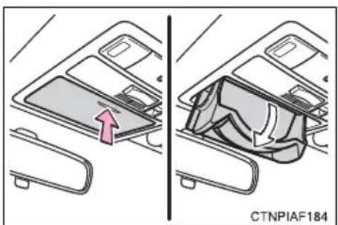
Diagram showing two views of a car interior with a highlighted component (no text or symbols)Arrows indicating operations

Indicates the action (pushing, turning, etc.) used to operate switches and other devices.

Indicates the outcome of an operation (e.g. a lid opens).
Before driving
1
1-1. EV system
Characteristics of the EV (Electric Vehicle) system 26
EV (Electric Vehicle) system precautions...... 32
Energy monitor/consumption screen...... 38
EV (Electric Vehicle) driving tips.... 41
1-2. Navigation system screen operations
Navigation system screen operations.... 44
1-3. Charging
Charging equipment...... 46
Power sources that can be used.... 50
Charging and pre-climate (Remote Climate Control) procedures.... 53
When normal charging cannot be carried out..... 88
Inspecting the charging cable 92
1-4. Key information
Keys.... 94
1-5. Opening, closing and locking the doors
Smart key system 96
Wireless remote control ... 108
Side doors.... 110
Back door.... 113
1-6. Adjustable components (seats, mirrors, steering wheel)
Front seats.... 118
Rear seats.... 121
Head restraints...... 127
Seat belts.... 131
Steering wheel 140
Anti-glare inside rear view mirror 141
Outside rear view mirrors.... 143
1-7. Opening and closing the windows
Power windows.... 146
1-8. Theft deterrent system
Immobilizer system ..... 149
Theft prevention labels..... 151
1-9. Safety information
Correct driving posture..... 152
SRS airbags.... 154
Front passenger occupant classification system..... 166
Child restraint systems..... 172
Installing child restraints.... 176
The RAV4 EV is considerably different from a conventional vehicle. Instead of using gasoline, the vehicle is driven using electricity in the rechargeable traction battery to power the electric motor. This technology is clean and has a low impact on the environment by not emitting exhaust such as CO_2 or NOx during operation.
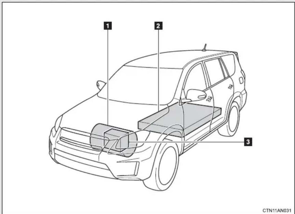
The illustration is an example for explanation purposes only and may vary from the actual vehicle.
1 Electric motor (traction motor)
2 Traction battery
Provides electricity to the electric motor and air conditioning system.
3 12-volt battery
Provides electricity to various vehicle functions such as the audio system, wipers, headlights and so forth.
Charging
The RAV4 EV is driven using electricity, received from an external power source, that is stored in the traction battery. Not only public charging stations, but also household electrical receptacles can be used for charging. Procedures are different from refueling a conventional vehicle. Therefore, make sure to read the following thoroughly.
● Charging equipment ( P. 46)
● Power sources that can be used ( P. 50)
●How to charge your vehicle and set the pre-climate schedule ( P. 53)
● When normal charging cannot be carried out ( P. 88)
● Inspecting the charging cable ( P. 92)
■When braking (regenerative braking)
The electric motor (traction motor) charges the traction battery. The driving range can be extended by actively using this regenerative braking to store electricity in the traction battery.
Vehicle Proximity Notification System
A sound is produced while driving to warn pedestrians, people riding bicycles or other people and vehicles in the surrounding area that the vehicle is approaching. The pitch of the sound adjusts according to vehicle speed. When vehicle speed is approximately 16 mph (25 km/h) or more, the warning system turns off.
"Range map" screen
The driving area possible on the current charge level can be displayed as a reference. Charge stations in the surrounding area of the current position can also be displayed. Press the “HOME” button, and then touch “EV” followed by “Range Map” on the screen to display the range map screen.
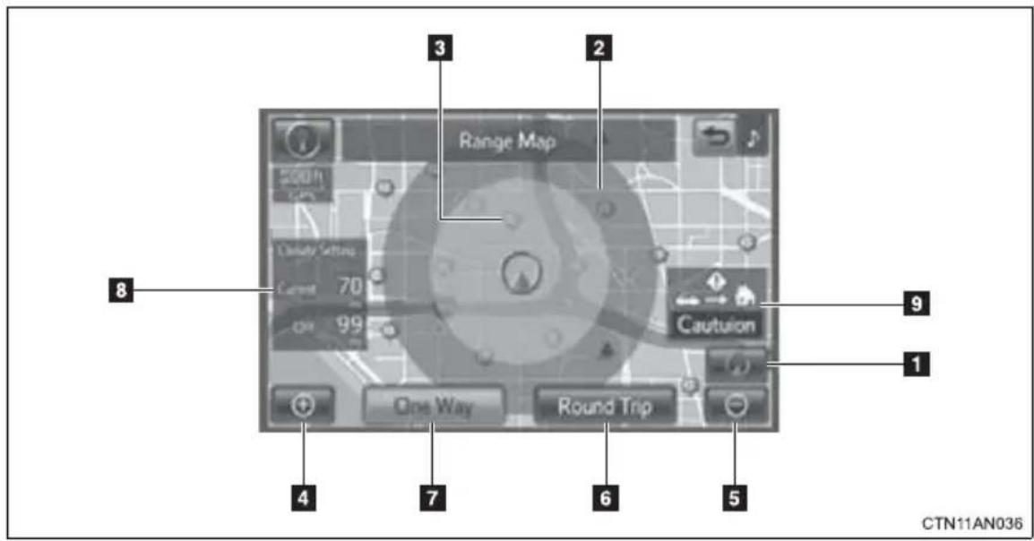
| No. | Name Function | |
| 1 | Current position | Touch to return to the current position if the map has been scrolled. |
| 2 | Range circle | Shows the driving range based on the current charge level. |
| 3 | Charge station | Shows the charge stations around the current position. |
| 4 | Zoom in button Touch to magnify the map scale. | |
| 5 | Zoom out button Touch to reduce the map scale. | |
| 6 | “Round Trip” | Touch to display the driving range for a round trip. (Displayed when route guidance is not being used.) |
| 7 | “One Way” | Touch to display the driving range for a one-way trip. (Displayed when route guidance is not being used.) |
| 8 | “Climate Setting” | Displays the driving range with the current air conditioning settings and with the air conditioning turned off. |
| 9 | Reachable Destination Guidance | When a destination is set, or when Home is registered, displays an estimation of whether the destination can be reached on the amount of charge remaining in the traction battery.For details refer to the “Navigation System Owner's Manual”. |
For details on ions that are displayed during route guidance, refer to “Map Screen” or “Starting Route Guidance” in the “Navigation System Owner’s Manual”.
■ Regenerative braking
During deceleration, kinetic energy from the vehicle is stored in the traction battery for later use. This occurs while driving in D or B position when:
●The acceleration pedal is released
●The brake pedal is applied
■12-volt battery recharging
The traction battery automatically recharges the 12-volt battery when the EV system is ON or while the traction battery is being charged from an electrical receptacle.
If the vehicle is not used for one month or more, there is a possibility the 12-volt battery may discharge. If this occurs, follow the correction procedures. ( P. 470)
■When not using the vehicle for an extended period of time
→P. 81
Charging
Be sure you maintain the traction battery charge level for your driving needs. If the traction battery fully discharges, the vehicle cannot be driven at all. Even when driving, keep early charging in mind. ( P. 53) If the amount of charge remaining in the traction battery becomes low, search for a charging station using the navigation system*.
* For details, refer to the "Navigation System Owner's Manual".
■Driving Range
Based on the amount of charge remaining in the traction battery, the air-conditioning system mode and so forth, the calculated driving range is displayed on the meter.
Depending on driving speed, road surface conditions, method of air-conditioning use, and so forth, the actual driving distance may increase or decrease. Keep early charging in mind.
■Noise and vibrations specific to an electric vehicle
Because an electric vehicle does not have the engine noise or vibrations that a conventional vehicle has, the driver may not notice that the ready indicator is illuminated and the vehicle is in a drivable condition. For safety reasons, always shift the shift position to P and apply the parking brake when parking the vehicle.
After starting the EV system, the following noises and vibrations may occur. These noises and/or vibrations are not signs of a malfunction. For example:
●Motor sounds coming from the motor compartment.
Electrical relay sounds may be heard from the traction battery when the EV system starts or stops.
●Sounds may be heard from the transmission and its surrounding area when the EV system starts or stops.
● Sounds may be heard due to regenerative braking when you depress the brake pedal or release the accelerator pedal.
●Motor sounds may be heard when accelerating suddenly.
●Operational and motor sounds may be heard when the brake pedal is depressed.
●The electric cooling fans in the front of the vehicle may be heard.
●Air conditioning operation sounds may be heard.
If the amount of charge remaining in the traction battery becomes low
→P. 53
■ Vehicle Proximity Notification System
In the following cases, the Vehicle Proximity Notification System sound may be difficult for pedestrians, people riding bicycles or other people and vehicles in the surrounding area to hear:
- When there is a lot of noise in the vicinity
- When it is raining or during strong winds
- When in the area surrounding the rear of the vehicle, rather than in front of the vehicle
■Maintenance, Repair and Disposal
Contact your Toyota dealer regarding maintenance, repair and disposal. When disposing of your vehicle, traction batteries are collected through Toyota dealers, and as such we appreciate your cooperation.
Please do not attempt to disassemble or service the EV system, as it contains high voltage (nearly 400 V), as well as parts that become extremely hot when the EV system is operating. Obey the caution labels attached to the vehicle.
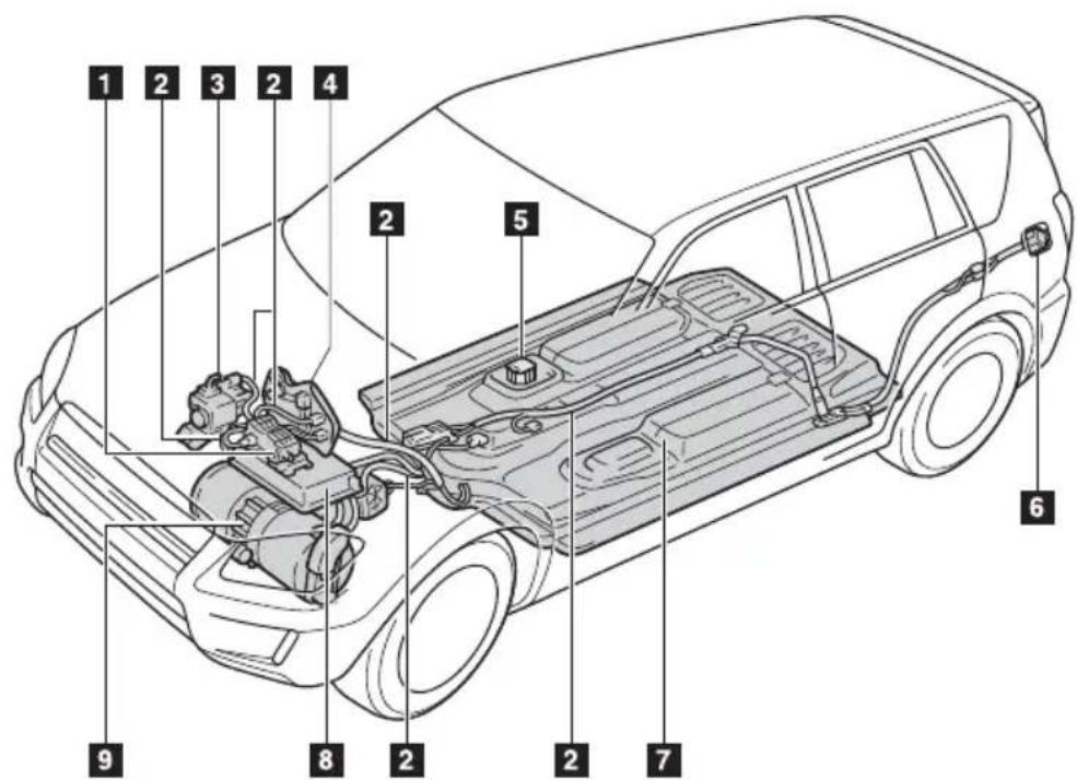
CTN11AN029
The illustration is an example for explanation purposes only and may vary from the actual vehicle.
1 Cabin coolant heater
2 High voltage cables (orange)
3 Air conditioning compressor
4 DC/DC converter
5 Service plug
6 Charging port
7 Traction battery
8 Charger
9 Electric motor (traction motor)
Emergency shut off system
When a certain level of impact is detected by the impact sensor, the emergency shut off system turns off the EV system and blocks off the high voltage current. If the emergency shut off system activates, your vehicle will not restart. To restart the EV system, contact your Toyota dealer.
Warning message
A message is automatically displayed when a malfunction occurs in the EV system or an improper operation is attempted.
natural_image
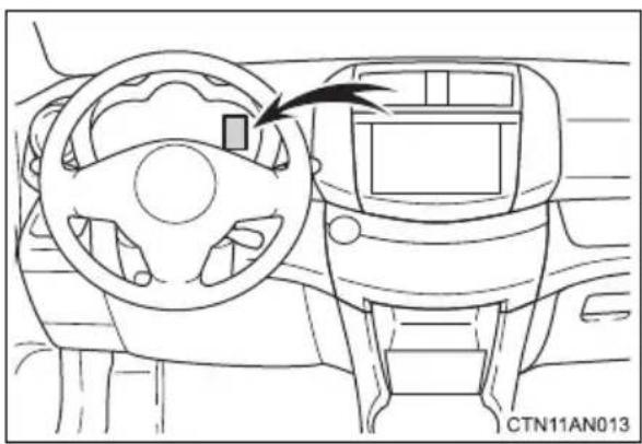
Interior view of a car dashboard and infotainment system (no text or symbols visible)If a warning message is shown on the multi-information display, read the message and follow the instructions. ( P. 427)
If a warning light comes on, a warning message is displayed, or the 12-volt battery has been disconnected
The EV system may not start. In that case, try to start the system again. If the “READY” indicator does not come on, contact your Toyota dealer.
Electromagnetic waves
●High voltage parts and cables on electric vehicles incorporate electromagnetic shielding, and therefore emit approximately the same amount of electromagnetic waves as conventional gasoline powered vehicles or home electronic appliances.
- Your vehicle may cause sound interference in some third party-produced radio parts.
■Traction battery (Lithium-ion battery)
The traction battery has a limited service life.
The traction battery capacity (the ability to store energy) reduces with time and use in the same way as other rechargeable batteries. The extent at which capacity reduces changes drastically depending on the environment (ambient temperature, etc.) and usage conditions, such as how the vehicle is driven and how the traction battery is charged. This is a natural characteristic of lithium-ion batteries, and is not a malfunction. In order to reduce the possibility of the capacity decreasing, follow the directions listed on P. 80, "Capacity reduction of the traction battery".

CAUTION
■High voltage precautions
The vehicle has high voltage DC and AC systems as well as a 12-volt system. DC and AC high voltage systems are very dangerous and can cause severe burns and electric shock that may result in death or serious injury.
●Never touch, disassemble, remove or replace the high voltage parts, cables or their connectors.
●The EV system will become hot after starting as the system uses high voltage. Be careful of both the high voltage and the high temperature, and always obey the caution labels attached to the vehicle.
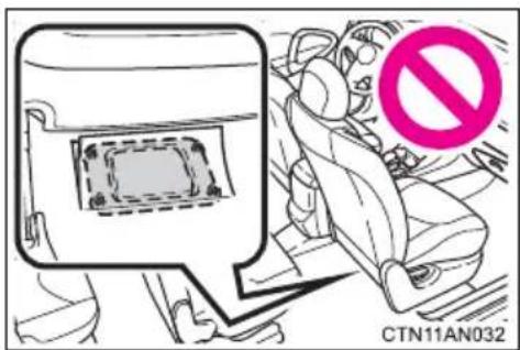
●Never try to open the service plug access hole located under the front passenger seat. The service plug is used only when the vehicle is serviced and is subject to high voltage.

CAUTION
Road accident cautions
Observe the following precautions to reduce the risk of death or serious injury:
- Stop the vehicle in a safe place, apply the parking brake while depressing the brake pedal, shift the shift position to P and turn the EV system off. Then gradually release the brake pedal.
●Do not touch the high voltage parts, cables or connectors. - If electric wires are exposed inside or outside your vehicle, an electric shock may occur. Never touch exposed electric wires.
- Do not touch the traction battery if liquid is leaking from or adhering to it. If electrolyte (Organic Carbonate-based electrolyte) from the traction battery comes into contact with the eyes or skin, it could cause blindness or skin wounds. In the unlikely event that it comes into contact with the eyes or skin, wash it off immediately with a large amount of water, and seek immediate medical attention.
- If electrolyte is leaking from the traction battery, do not approach the vehicle. Even in the unlikely event that the traction battery is damaged, the internal construction of the battery will prevent a large amount of electrolyte from leaking out. However, any electrolyte that does leak out will give off acidic fumes. These fumes are an irritant to skin and eyes and could cause acute poisoning if inhaled.
- Do not bring burning or high-temperature items close to the electrolyte. The electrolyte may ignite and cause a fire.
- If a fire occurs in the electric vehicle, leave the vehicle as soon as possible. Never use a fire extinguisher that is not meant for electrical fires. Using even a small amount of water may be dangerous.
- If your vehicle needs to be towed, do so with the front wheels raised. If the wheels connected to the electric motor (traction motor) are on the ground when towing, the motor may continue to generate electricity. This may cause an electricity leakage leading to a fire. ( P. 413)

CAUTION
- Carefully check to see if there are exposed high voltage parts or cables. Never touch the parts or cables. (→P. 32)
- Carefully inspect the ground under the vehicle. If you find that liquid (other than water from the air conditioning) has leaked onto the ground, the traction battery may have been damaged. Leave the vehicle as soon as possible.
■ Traction battery (lithium-ion battery) replacement and disposal
Do not replace, dispose of, modify, or reuse the traction battery and do not use it for anything other than its intended use. Contact your Toyota dealer for replacement or disposal.
If the traction battery is replaced, disposed of, modified or reused in an improper way, or if the traction battery is used in a way it is not intended for, there is a risk of severe burns and electrical shock that may result in death or serious injury.
Also, improper handling of the traction battery can lead to environmental hazards.
■Caution while driving
The RAV4 EV does not make the sounds that a gasoline vehicle makes. As such, pedestrians, people riding bicycles or other people and vehicles in the surrounding area may not be aware of the vehicle starting off or approaching them, so take extra care while driving.
You can view the status of your EV system on the navigation system.
Trip Information screen/Past record screen
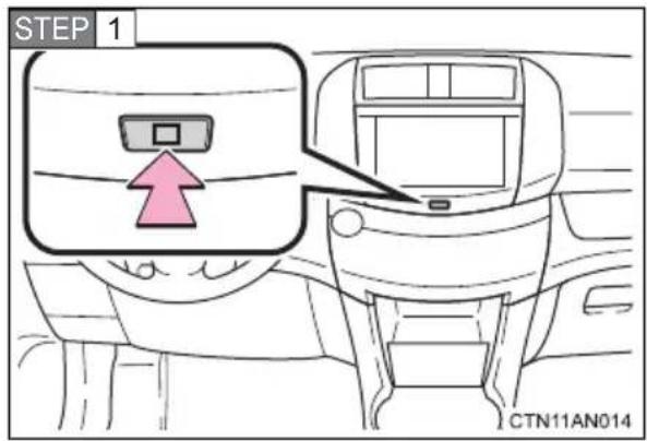
Press the HOME button.
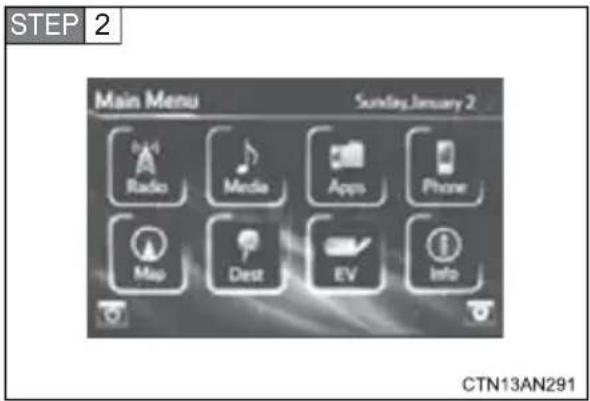
Touch "EV" on the "Main Menu" screen.
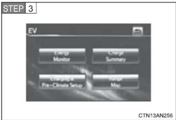
Touch "Energy Monitor" on the "EV" screen.
■Trip information screen
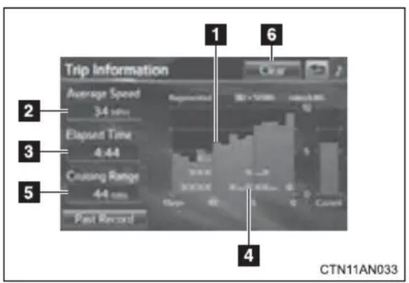
1 Power consumption in the past 15 minutes
2 Displays the average vehicle speed since the EV system was started.
3 Displays the elapsed time since the EV system was started.
4 Regenerated energy in the past 15 minutes
One symbol indicates 50 Wh.
Up to 5 symbols are shown.
5 Displays an estimated cruising range
6 Reset the power consumption and the regenerated energy for the past 15 minutes.
Selecting “Yes” on the following screen will confirm resetting of all the data.
The image is an example only, and may vary slightly from actual conditions.
Past record screen
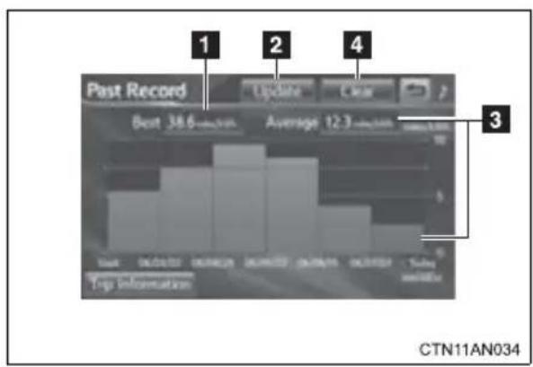
1 Best past power consumption
2 Update
The average power consumption and graph are updated, and a new average power consumption record begins.
3 Average power consumption
Displays a maximum of five past records of the average power consumption.
4 Reset the past records and best past power consumption.
Selecting "Yes" on the following screen will confirm resetting of all the data.
The image is an example only, and may vary slightly from actual conditions.
Observe the following to reduce traction battery consumption and increase driving range.
■Driving in normal mode:
Normal mode (when compared with sport mode) allows the most efficient driving. ( P. 208)
Route selection
In addition to a driving style of repeated acceleration and deceleration, driving on routes that have steep inclines and long waits at traffic lights will lead to poor power consumption. Check traffic reports before leaving, avoid delays and drive on flat roads as much as possible. When encountering a delay, gently release the brake pedal to allow the vehicle to move forward slightly while avoiding overuse of the accelerator pedal. Doing so can help control excessive energy consumption.
■Use of EV System Indicator
Keeping the EV System Indicator needle within ECO area can help improve Eco-friendly driving. ( P. 221)
■When braking the vehicle
Make sure to operate the brakes gently and in good time. A greater amount of electrical energy can be retained when slowing down.
■ Highway driving
Control your speed, keep at a constant speed and obey speed limits. Also, before stopping at a toll booth or similar, allow plenty of time to release the accelerator and slowly stop the vehicle using regenerative braking and the brake pedal. A greater amount of electrical energy can be retained while slowing down.
Air conditioning system
Use the air conditioning only when necessary. Doing so can help control excessive energy consumption. Even when the air conditioning is on, driving range can be extended by setting it to “ECO LO” or “ECO HI”, or by turning the A/C off. ( P. 276) If pre-climate (Remote Climate Control) is operated before departure when the vehicle is plugged in, depending on air-conditioning specifications, traction battery power consumption can be reduced. ( P. 53)
Additionally, keep in mind the following during heavy air conditioning use in summer and winter.
In summer: In high temperatures, use the recirculated mode. Doing so can help control excessive power consumption.
In winter: By combining use with the seat heater, the set temperature for the heater can be reduced. This can increase power efficiency.
■ Checking tire inflation pressure
Make sure to check the tire inflation pressure frequently. Improper tire inflation pressure can cause poor power consumption.
Also, as snow tires can cause large amounts of friction, their use on dry roads can lead to poor power consumption. Use a tire that is appropriate for the season.
Luggage
Carrying luggage can lead to poor power consumption. Avoid carrying unnecessary luggage. Installing a roof rack can also cause poor power consumption.
■Pre-driving warm-up
When the charging schedule is set
According to departure time, traction battery warm-up is performed automatically. Therefore, the vehicle can be driven immediately. ( P. 203)
When the charging schedule is not set
If the traction battery's available power becomes too low (due to temperature or charge level), a warning message will be shown on the multi-information display. Until battery warm-up is completed, the EV system may not be able to be started or power output may be limited while driving. Follow the correction procedures. (→P. 427)
■Sport mode
When sport mode is selected, acceleration performance is maximized, and maximum speed is increased but vehicle efficiency and driving range may be reduced. ( P. 208)
Every time the vehicle is turned on, normal mode will automatically be selected. If sport mode is desired, it must be selected manually.
1-2. Navigation system screen operations
Navigation system screen operations
Operations are performed by touching the navigation system screen directly with your finger.
■Main operations
| Operation method Outline Main use | ||
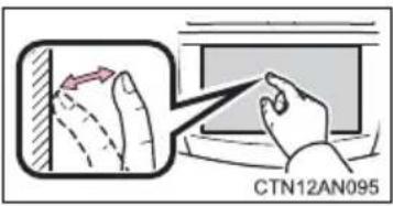 | TouchQuickly touch and release once. | Changing and selecting various settings. |
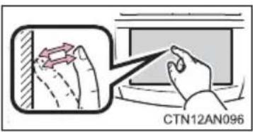 | Double tap*Quickly touch and release twice. | Changing the map scale. |
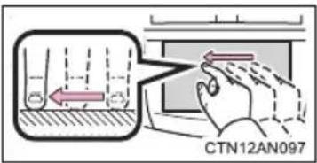 | Drag*Touch the screen with your finger, and move the screen to the desired position. | Moving around the map, adjusting audio volume, etc. |
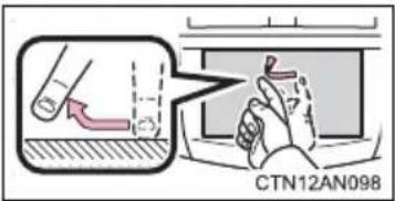 | Flick*Quickly move the screen left or right by flicking with your finger. | Moving around the map, skipping to the next page of a list, etc. |
*: The above operations may not be performed on all screens.
■Navigation system screen operations
In the following conditions, operations may not be performed despite touching the screen. Also, take care because they may cause incorrect operations.
- When wearing gloves
- When operations are performed with your fingernails
- When operations are performed while foreign matter is stuck to the screen
- When operations are performed using 2 fingers or more
- When operations are performed with a wet finger
NOTICE
■When using the navigation system screen
The screen is designed to be touched softly. Do not press the screen with sharp objects such as fingernails, the ends of ballpoint pens and pins. Doing so may damage the screen.
This vehicle is charged by connecting to an external power source.
■ Charging equipment
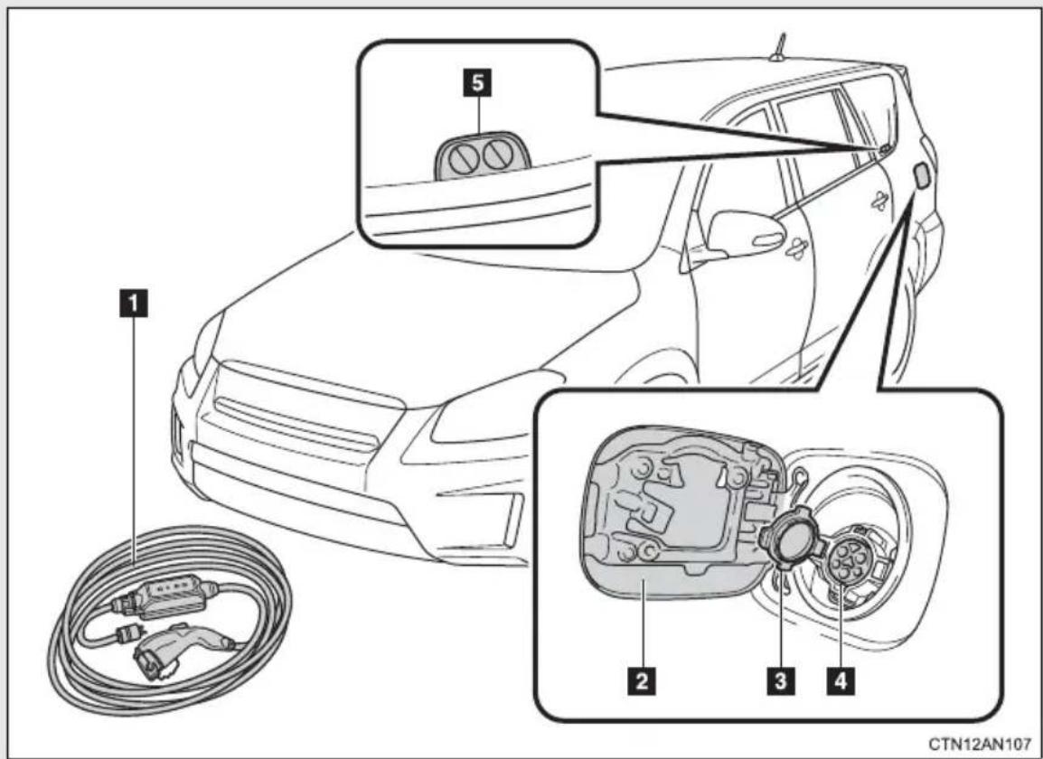
1 Charging cable
2 Charging port door
3 Charging port cap
4 Charging port
5 Charging indicator
■The names of each part of the charging cable
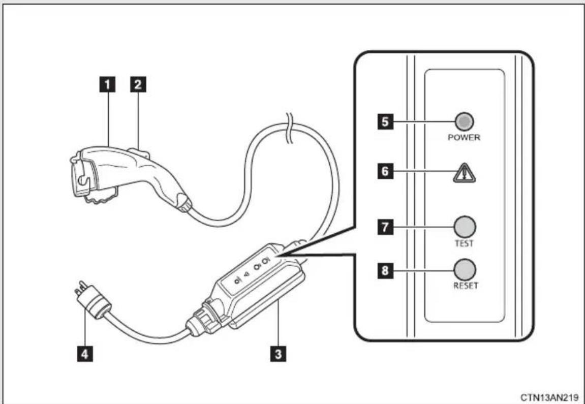
1 Charging connector
2 Latch release button
3 CCID (Charging Circuit Interrupting Device)
4 Plug*
5 Power indicator
6 Error warning indicator
7 Test button
8 Reset button
*: The shape of the plug differs in accordance with the voltage and the target region.
Safety functions
The CCID (Charging Circuit Interrupting Device) has the following safety features.
■Electrical leakage detection function
If an electrical leakage is detected during charging, the power source will be automatically interrupted, thus preventing fires or electrical shocks caused by electrical leakage.
If the power source is interrupted, the error warning indicator will illuminate.
If the power source is interrupted: →P.91
■Electrical leakage test function
The electrical leakage detection function can be tested prior to charging to confirm that it is operating correctly.
When the test button is pressed while the plug is connected to an external power source, the error warning indicator should illuminate. ( P. 59)
■Conditions for supplying current to the vehicle
The CCID (Charging Circuit Interrupting Device) is designed to prevent electrical current from being supplied to the charging connector when it is not connected to the vehicle, even if the plug is inserted into an electrical receptacle.
Charging method
●The charging cable included with the vehicle is designed to be connected only to an AC 120 V power source.
Toyota strongly recommends that the vehicle be charged using a 240 V charging station that is compliant with SAE J1772. This offers a faster charge time than 120 V (level 1) charging. If you would like more information on obtaining 240 V (level 2) charging in your home, please consult the Toyota dealer from whom you purchased your RAV4 EV, any other dealership authorized to sell the RAV4 EV or visit http://toyota.leviton.com/. For more information regarding public charging stations, please refer to the "Navigation System Owner's Manual" regarding Charging Station POI or Apps.

CAUTION
■ When using the charging cable and CCID (Charging Circuit Interrupting Device)
Observe the following precautions.
If you do not follow them, fire, electrical shock or damage may occur, possibly resulting in death or serious injury
- Do not attempt to disassemble or repair the charging cable, charging connector, plug or CCID (Charging Circuit Interrupting Device). If a problem arises with the charging cable or the CCID (Charging Circuit Interrupting Device), stop charging immediately and contact your Toyota dealer.
- Do not subject the charging cable, charging connector, plug or CCID (Charging Circuit Interrupting Device) to strong force or impact.
- Do not forcefully fold the charging cable or damage the charging cable with sharp objects.
- Do not insert foreign objects into the charging connector or plug.
- Do hold the body of the charging connector or plug when removing or inserting.
- Remove the charging connector from vehicle's charging port FIRST, before removing the plug from the electrical receptacle.
● Avoid exposure of plug to water or moisture. - Do not attempt to modify the charging cable, charging connector, plug or CCID (Charging Circuit Interrupting Device).
A charging solution that fulfills the following criteria is necessary for charging this vehicle. Confirm that the criteria is met before charging.
Power sources
- Connect the charging plug cable to an AC 120 V electrical receptacle (NEMA 5-15R or NEMA 5-20R) with a Ground-Fault Circuit-Interrupter (GFCI) and with an over current circuit breaker in the service panel.
● Toyota recommends use of a dedicated receptacle with a single socket. If the receptacle has two sockets, do not plug any other items into the other socket.
●This vehicle is expected to charge at public charging stations that are compliant with SAE J1772. The navigation system can show you a list of nearby public charging stations. Please refer to the “Navigation System Owner's Manual” regarding Charging Station POI or Apps for more information. - When charging outdoors, make sure to connect to a raintight electrical receptacle type that is appropriate for outdoor use.
■Electrical receptacles that can be connected
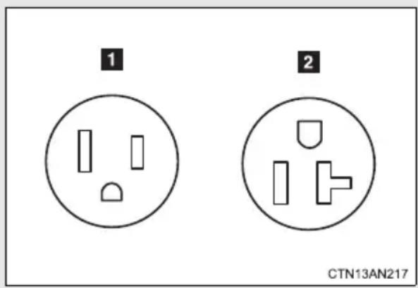
1 NEMA 5-15R electrical receptacle
2 NEMA 5-20R electrical receptacle
The illustration is an example shown for demonstration purposes, and may differ from the actual configuration.
■The charging environment
For safer charging, the following charging equipment and settings are recommended.
●Weatherproof electrical receptacle
When charging outside using the Toyota-provided charging cable, connect to an appropriate outdoor receptacle with a "while-in-use" cover.
●Dedicated circuit
- To reduce the risk of fire, connect only to a circuit provided with 15A or 20A maximum branch circuit over-current protection in accordance with the National Electric Code, ANSI/NFPA 70.
- To reduce the risk of electric shock when working with the plug, connect to an electrical receptacle with a Ground-Fault Circuit-Interrupter (GFCI) or that has an Earth Leakage Circuit Breaker installed.
■ Using a DC charger
DC charging equipment cannot be used with this vehicle.

CAUTION
Electrical Malfunctions
When charging the vehicle, make sure you observe the precautions included in this manual.
Failure to do so or using a power source that does not meet the necessary conditions can cause a fire, from electrical leakage or overheating, or electric shock that may result in death or serious injury.

CAUTION
■Power sources precautions
Observe the following precautions.
If you do not follow them, fire, electrical shock or damage may occur, possibly resulting in death or serious injury.
- Connect to an AC 120 V electrical receptacle (NEMA 5-15R or NEMA 5-20R) with a Ground-Fault Circuit-Interrupter (GFCI) and with an over current circuit breaker in a service panel.
natural_image
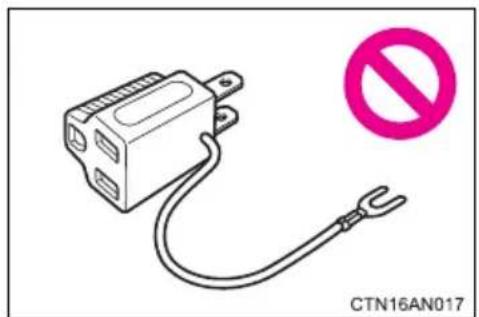
Simple line drawing of a connector with a power cord and a no-smoking symbol (no text or labels)- Do not connect the charging cable to a multi-outlet adapter, multi-plugs, or conversion plug.
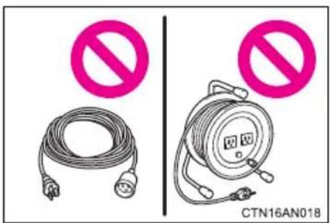
- Do not connect the charging cable to an extension cable. The cable may overheat and does not contain a Ground-Fault Circuit-Interrupter (GFCI).
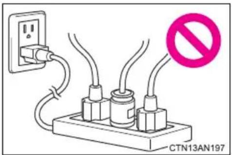
- Do not connect to a power strip.
- Do not perform charging with a damaged electrical receptacle.
On the RAV4 EV, setting the charge and pre-climate (Remote Climate Control) schedule is performed on the navigation system's screen. A variety of settings are available including charging and pre-climate operations according to departure time. After thoroughly reading the following instructions, make sure to correctly follow the procedures when charging your vehicle.
■Charging and pre-climate (Remote Climate Control)
Depending on the settings of the following functions, this vehicle does not start charging by simply just plugging in the charging cable.
Set any of the following functions before or after charging.
| System Details | |
| Charging | Charge immediately functionRegardless of the charging schedule settings, starts charging immediately. (→P. 64)However, when this function is used, pre-climate schedule operations cannot be performed simultaneously. |
| Scheduled charging functionThe time when charging is to be completed by can be set for each day of the week. (→P. 66)Even when the schedule is set, the charge immediately function can be selected if the EV system is off. (→P. 64)After the immediate charge is complete, the schedule will be returned to.If the schedule is not set for any days of the week, the charge immediately function will be automatically selected. | |
| Pre-climate (Remote Climate Control)* | The time when pre-climate operations are to be completed by can be set for each day of the week.Cabin temperature is adjusted before departure by performing climate control operations, thereby reducing traction battery consumption after departure. If these operations are performed while the vehicle is plugged in, the traction battery's power consumption is reduced, increasing driving range. (→P. 66)If the amount of charge remaining in the traction battery is 50% or less at the time pre-climate operations begin, pre-climate operations will not be performed in order to preserve driving range. |
*: By using a smart phone, pre-climate operations and so forth can be performed from a distant location. (→P. 58)
■ Important things to check before charging and pre-climate operations (Remote Climate Control)
Before charging and pre-climate operations, always check that:
● The parking brake is securely set ( P. 216)
● The shift position is in P ( P. 206)
●All windows and doors are closed
●The motor compartment hood is securely closed
If the hood is open the electric cooling fans will not operate, raising the temperature of the charger and traction battery. This may increase charging time or cause charging to be aborted.
● All lights are turned off (For example, the headlights, emergency flashers, interior lights, etc.)
If any lights are turned on, then these features will consume electricity, and charging time will increase.
■Items to be regularly inspected
→P.92
■By My Departure Schedule Setting
When the EV system is turned off, the screen changes to the charging and pre-climate settings screen. If no operations are performed for approximately 30 seconds, the screen turns off.
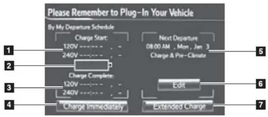
CTN13AN286
The actual screen may vary slightly, depending on settings.
| Function Details | |
| 1 Charge start | Displays the time that charging started (if charging is in progress or complete) or will start (if charging schedule is set). |
| 2 Battery charge amount | Displays the current amount of charge remaining in the traction battery. |
| 3 Charge complete schedule | Displays the schedule when charging will be completed according to voltage. |
| 4 Charge immediately button | Sets the immediate charge function on/off. |
| 5 Next departure schedule | Displays the currently set next departure schedule and charge/pre-climate settings. |
| 6 Departure schedule Edit button | Edits and sets the next departure schedule and charge/pre-climate schedule. |
| 7 Extended charge mode setting button | Sets extended charge mode on/off. |
Charge and Pre-Climate Schedule Setting Screen
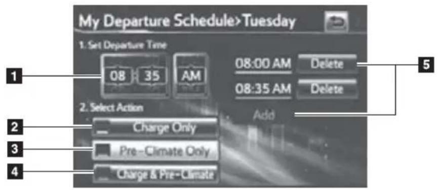
CTN13AN252
The actual screen may vary slightly, depending on settings.
| Function Details | |
| 1 Set departure time dial | Set the desired time and day by flick-ing up or down. |
| 2 Charge Only Button | To finish charging before the setdeparture time. |
| 3 Pre-Climate Only Button | To finish pre-climate operationsbefore the set departure time. |
| 4 Charge and Pre-ClimateButton | To finish both charging and pre-cli-mate operations before the setdeparture time. |
| 5 Add/Edit/Delete Button | To add, edit or delete items in theschedule that were set using screenbuttons 1 . |
Charge mode
The RAV4 EV has the following 2 charge modes.
After understanding the characteristics of each mode, select the appropriate mode according to usage instructions.
| Charge mode | Charge amount* | Details |
| Normal charge mode | Approximately 80% | A mode that combines maximizing vehicle performance and traction battery life. Toyota recommends charging using this mode whenever long distance driving is not necessary. |
| Extended charge mode (→P. 72) | Approximately 100% | A mode that maximizes driving range on a single charge. Continued use of this mode may contribute to the reduction of the traction battery capacity over the vehicle life. |
*: This value is only a reference value, for a traction battery without any capacity deterioration. Depending on conditions such as air-conditioning system usage, road conditions, years of usage and so forth, the value may increase or decrease.
■Linked smart phone function
For drivers who own a smart phone and have an active Entune subscription, several features are available to remotely interact with your vehicle.
For details, please refer to http://www.toyota.com/entune/ or call 1-800-331-4331
Plugging in the charging cable
STEP 1 Prepare the charging cable
Insert the charging cable's plug into the electrical receptacle of the external power source.
Make sure that the standards of the electrical receptacle and charging cable's plug match. (→P. 50)
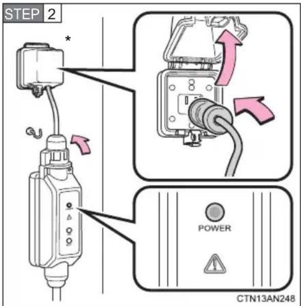
Check that the power indicator of the CCID (Charging Circuit Interrupting Device) is illuminated. (If it does not illuminate, refer to the text on page 88.)
To reduce the burden on the electrical receptacle and charging cable plug, Toyota recommends hanging the CCID (Charging Circuit Interrupting Device) on a hook or similar.
When charging outdoors, make sure to use a "while-in-use" cover as shown in the illustration.
*: "While-in-use" cover.
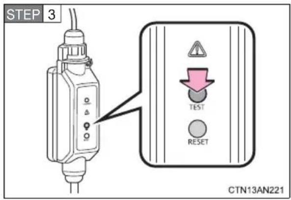
Press the test button on the CCID (Charging Circuit Interrupting Device) to check that the electrical leakage detection function operates properly.
If the error warning indicator illuminates when the test button is pressed, the function is operating correctly.
After the test has been completed, press the reset button to turn off the error warning indicator. Charging cannot be carried out while the error warning indicator is illuminated.
If the error warning indicator does not come on even if the test button is pressed, it is likely that the function is not operating correctly. Stop charging immediately and contact your Toyota dealer.
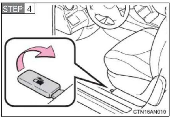
Pull up the charging port door lever.
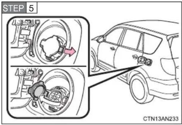
Unlock the charging port cap by moving the lock.
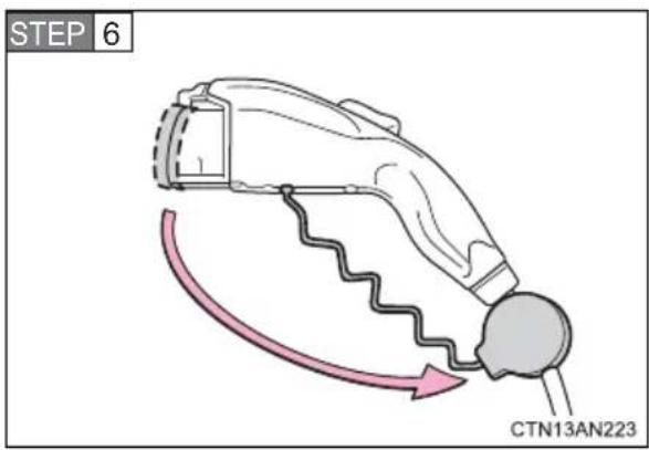
Remove the charging connector cap.
Affix the cap to the cable.
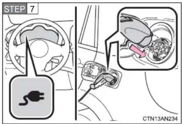
Confirm the charging cable connector's direction and insert it into the charging port.
When inserting the connector, insert it without pressing the latch release button.
Align with the guide position shown on the underside of the charging connector with the charging port, and push it in straight and firmly until a click is heard. Then, confirm that the connector is securely locked.
When plugging in has been completed correctly, the plug-in indicator on the meter comes on in green. If there has been a problem with plugging in, the plug-in indicator comes on in yellow. (→P. 419)
If the schedule is not set for any days of the week or the charge immediately function is selected, charging will begin by simply plugging in the charging cable.
If the EV system is on when the vehicle is plugged in, the READY indicator will automatically turn off and a message will be shown on the multi-information display. (→P. 443)
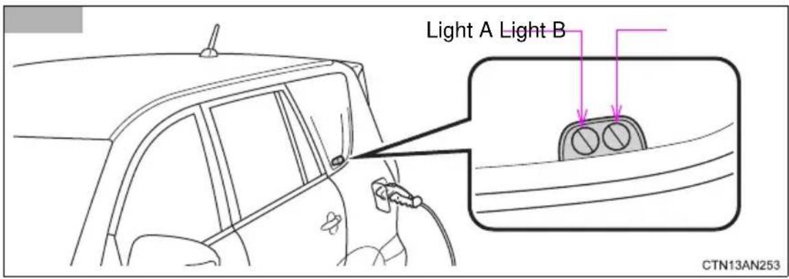
Check the status of the charging indicator.
The charging indicator consists of 2 lights that display charging status by illuminating, flashing and turning off as follows.
| Charging Status | Charging Indicator | |
| Light A Light B | ||
| The charging cable is connected to the vehicle and the charging and/or pre-climate schedule is set | Lights A and B flash on and off alternatively for 10 minutes. (After 10 min. both lights remain off until charging starts) | |
| Charge level is less than 49% Flashes Off | ||
| Charge level is between 50% and less than 99% | Illuminates Flashes | |
| Charging is complete | Both lights A and B illuminate for 10 minutes. (After 10 min. both lights turn off) | |
| Malfunction occurred during charging | Both lights A and B quickly flash simultaneously for 10 seconds. (After 10 sec. both lights turn off) | |
The indicator lights will not flash or turn on when the charging cable is not connected properly.
During charging, current charging status and the estimated time until charging will be completed can be confirmed on the multi-information display or navigation display. ( P. 74)
The error warning indicator of the CCID (Charging Circuit Interrupting Device) has illuminated during charging: →P.88
Charging immediately
■ Charging using the Charge Immediately function
STEP 1 Turn the EV system off.
The charge settings screen will be displayed. If no operations are performed for approximately 30 seconds, the screen turns off.
When the charging schedule is not set or charging immediately has been set while the EV system was on.
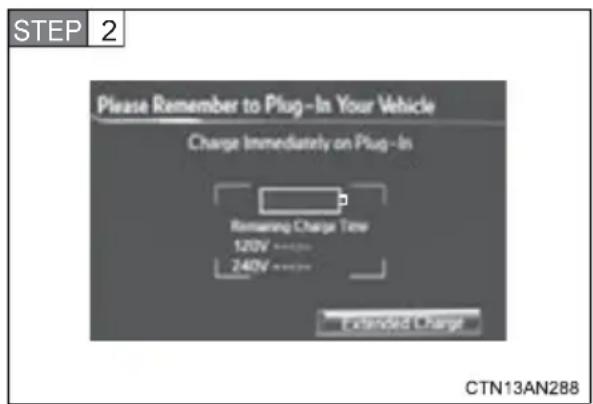
When this screen is displayed, proceed to step 3.
To change charging mode to normal/extended charge mode: →P.72
When the charging schedule is set.
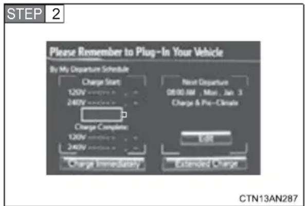
Touch "Charge Immediately".
After operations have been completed, the "Charge Immediately" screen button indicator illuminates.
This mode is a one time immediate charge. Once the charge is complete, the schedule will be returned to.
To change charging mode to normal/extended charge mode: →P.72
To set the schedule to charge the vehicle and/or to use the pre-climate: →P.66
STEP 3 Plug in the charging cable. ( P. 59)
Charging will start.
■Setting charge mode to charge immediately in advance
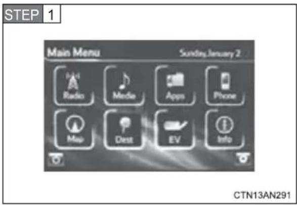
Touch "EV".
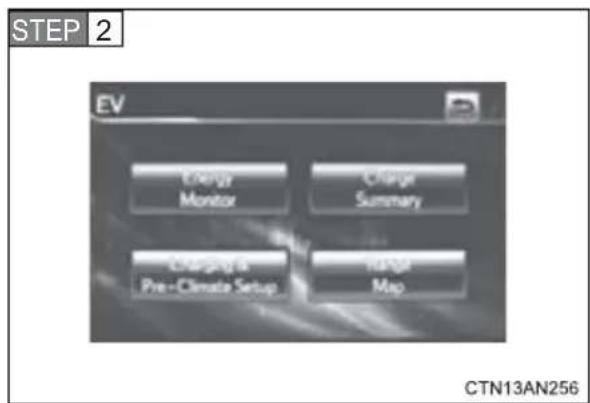
Touch "Charging & Pre-Climate Setup".
Touch or flick the screen to the right to display the "Charge Immediately on Plug-in" screen.
If schedule is not set:
This step is skipped.
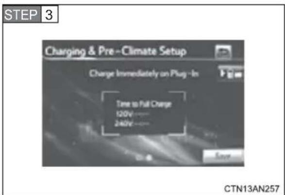
Touch "Save".
If "Save" is not touched, the changes will not be reflected in the charging schedule.
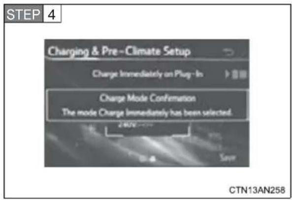
A screen advising that charge mode has been changed to immediate charge is displayed. The EV screen is returned to after a few seconds.
STEP 5 Turn the EV system off.
The charge settings screen will be displayed for approximately 30 seconds.
To change charging mode to normal/extended charge mode: →P.72
STEP 6 Plug in the charging cable ( P. 59)
Charging will start.
The estimated time charging will be completed in is displayed if an immediate charge is performed.
Start charging according to departure time and the set pre-climate completion time
■Setting the charging and pre-climate schedule in advance
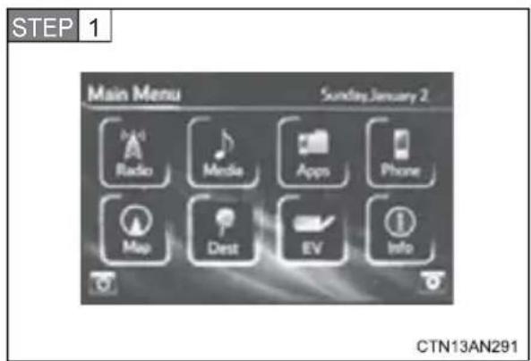
Touch "EV".
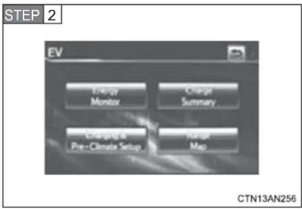
Touch "Charging & Pre-Climate Setup".
Touch or flick the screen to the left to display the "By My Departure Schedule" screen.
If schedule is set: This step is skipped.
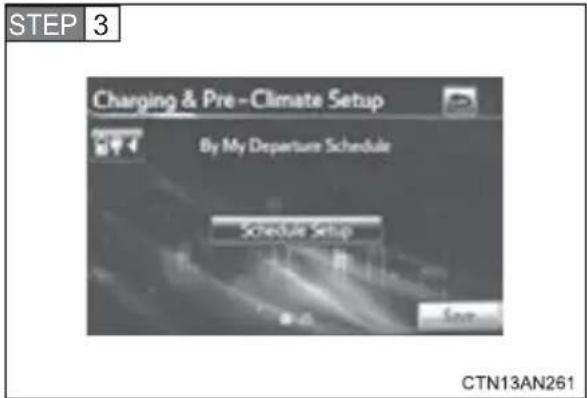
Touch "Schedule Setup".
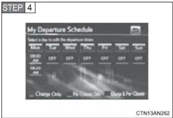
Touch the desired day to be set.
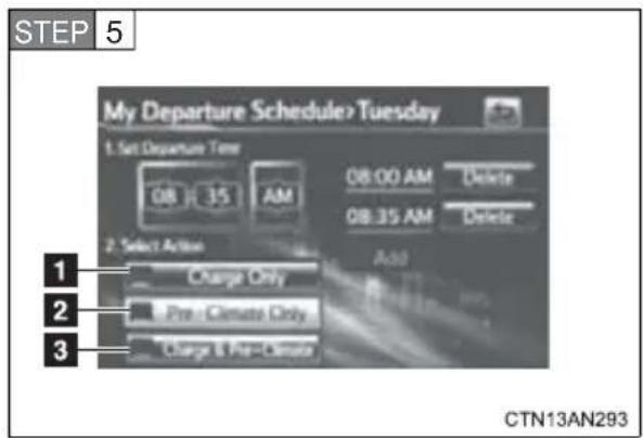
Flick the schedule to the desired time for charging and/or pre-climate to be completed. Touch the action to be completed by the set time.
1 Charge only schedule setting
2 Pre-climate only schedule setting
3 Charging and pre-climate schedule setting
Up to 3 actions can be set for a single day by touching "Add".
To delete the set action, touch "Delete".
Two actions cannot be set to the same time.
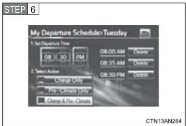
After settings have been com-
pleted, touch twice to
return to the "By My Departure Schedule".
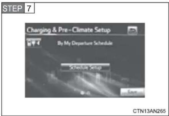
Touch "Save".
If "Save" is not touched, the changes will not be reflected in the charging schedule.
When the charging schedule is only set for some days of the week.
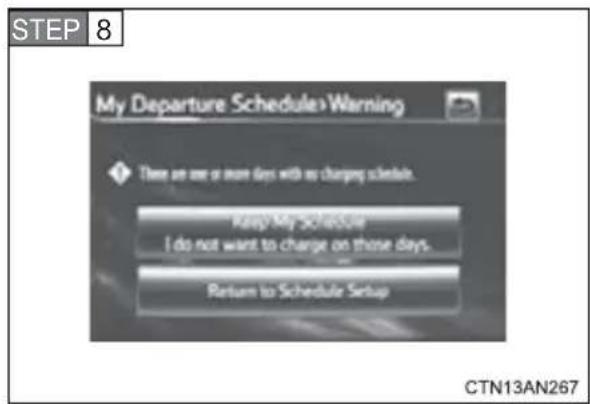
If “Keep My Schedule” is touched, setting the charging schedule will be completed and the display will return to the EV screen.
Touch "Return to Schedule Setup" to set the charging schedule for additional days.
When the charging schedule is set for each day of the week.
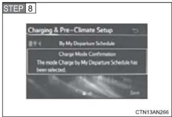
A screen advising settings have been completed is displayed. The display will return to the EV screen after a few seconds.
■Adjusting the charge schedule's next departure after the schedule has been set (One time departure)
In order to use this function, it is necessary to set the schedule beforehand. ( P. 66)
STEP 1 Turn the EV system off.
The charge settings screen will be displayed. If no operations are performed for approximately 30 seconds, the screen turns off.
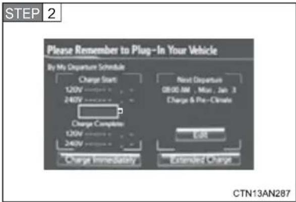
Touch "Edit".
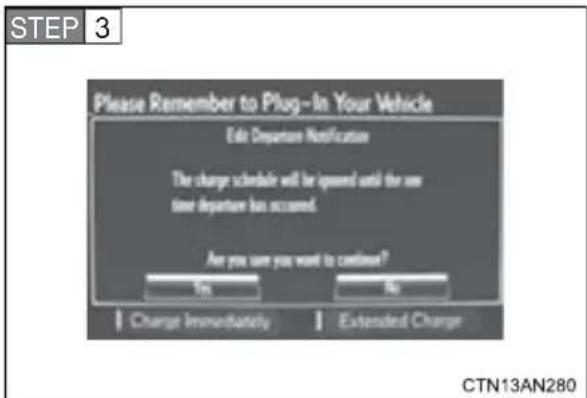
Touch "Yes".
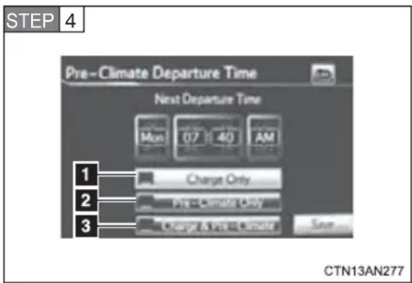
Flick the schedule to the desired day and time for charging and/or pre-climate to be completed. Touch the action to be completed by the set day and time.
1 Charge only schedule setting
2 Pre-climate only schedule setting
3 Charging and pre-climate schedule setting
Touch "Save" to start the selected action.
To cancel, touch
STEP 5 The set schedule will be displayed.
To change the set action or schedule, return to step 2.
To change charging mode to normal/extended charge mode: →P.72
To charge immediately: →P.64
STEP 6 Plug in the charging cable. ( P. 59)
Changing to normal/extended charge mode
STEP 1 Turn the EV system off.
The screen will change to the charging schedule screen. The screen will turn off after approximately 30 seconds if no operations are performed. Depending on “Charging & Pre-Climate Setup” settings, the displayed screen will differ.
When the vehicle is in extended charge mode, an extended charge reminder is displayed on the screen for a few seconds.
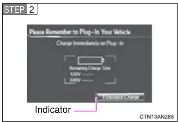
Touch "Extended Charge".
The current charge mode can be confirmed by checking the indicator on the "Extended Charge".
Illuminated:
Extended charge mode
Not illuminated:
Normal charge mode
To normal charge mode
STEP 3 The indicator will turn off, showing that the vehicle is in normal charge mode.
To extended charge mode
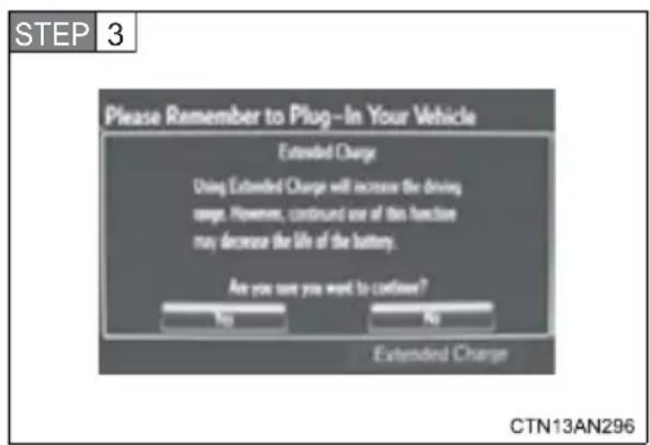
Touch “Yes” if it is desired to change to extended charge mode after reading the contents of the confirmation screen.
If "No" is touched, or there are no operations for a few seconds, the previous screen will be returned to.
STEP 4 When settings are completed, the indicator illuminates.
Unplugging the charging cable
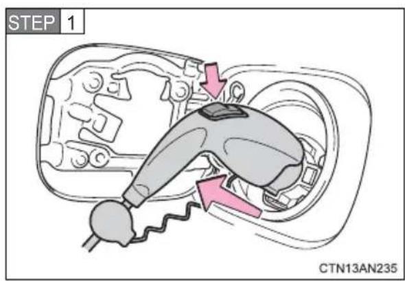
Pull the charging connector towards you while pressing the latch release button.
If the charging connector is disconnected during charging (while the charging indicator indicates the vehicle is being charged), charging will be interrupted.
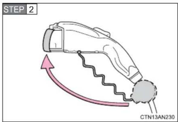
Attach the charging connector cap.

Close the charging port cap, and then close the charging port door.
Firmly push the charging port cap and charging port door, and check that they are securely locked.
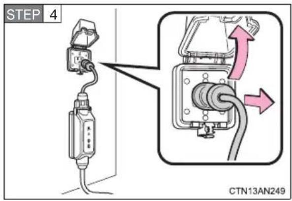
Remove the plug from the electrical receptacle when the charging equipment will not be used for a prolonged period of time.
Hold the body of the plug when removing.
Make sure to put the cable away immediately after disconnecting. (→P. 87)
When leaving the plug inserted, inspect the plug and connector once a month to check if dirt or dust has accumulated.
Contents shown on the multi-information display
A variety of information regarding charging is shown on the multi-information display.
■Results of Charging and Pre-climate Display
When charging/pre-climate operations are being performed or after they have finished, the following information is displayed according to vehicle conditions when the driver's door is opened for approximately 30 seconds or until the "POWER" switch is turned to ON mode.
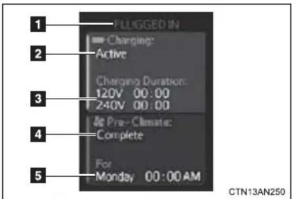
| Name Details | |
| 1 Plug connection information | Displays if plug is currently plugged in or not. |
| 2 Current charging status Displays current charging status. | |
| 3 Estimated charging time | Displays both 120 V and 240 V estimated charging times.When the plug is plugged in, only the voltage of the connected receptacle is displayed. |
| 4 Pre-climate result | Displays result of pre-climate operations (if they were completed or interrupted and so forth). |
| 5 Departure time* | Displays scheduled departure time pre-climate operations were performed for. |
*: If pre-climate operations are performed using a smart phone, this will not be displayed even if the driver's door is opened. (→P. 58)
In the following conditions, only the plug connection information will be displayed:
- When the “POWER” switch is turned to ON mode after charging/pre-climate operations.
- When the charging/pre-climate schedule is not set.
If pre-climate operations are performed using a smart phone, pre-climate result will be displayed. ( P. 58)
Setting and changing the schedule ( P. 66)
■ Charging information and warning messages
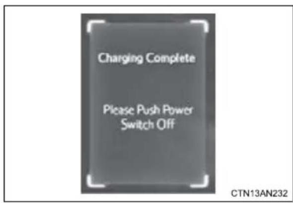
The first time the “POWER” switch is turned to ON mode after charging is completed, a message detailing the results of the charge is shown. Also, if an operation that cannot be carried out during charging was attempted, a warning message will be shown.
Comply with the instructions in the message and perform any necessary operations. (→P. 443)
Confirming current charge settings
The amount of charge remaining in the traction battery and charging/pre-climate schedule settings can be confirmed.
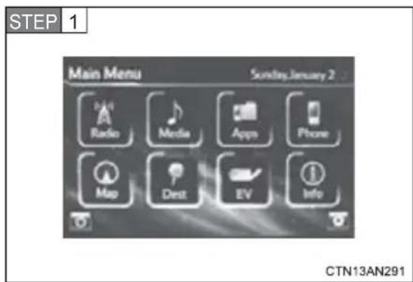
Touch "EV".
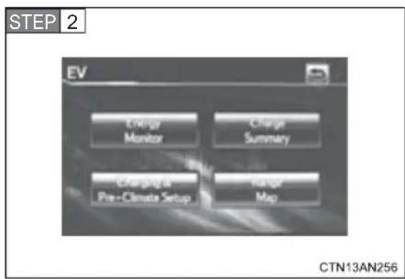
Touch "Charge Summary".
When the charging schedule is not set or charging immediately has been set while the EV system was on.
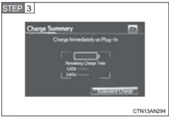
Confirm that charge immediately mode is set.
When the charging schedule is set.
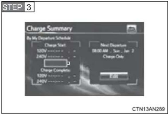
Confirm the next charging/pre-climate schedule.
If it is desirable to charge before the next scheduled charge, use one time departure.
Touch "Edit".
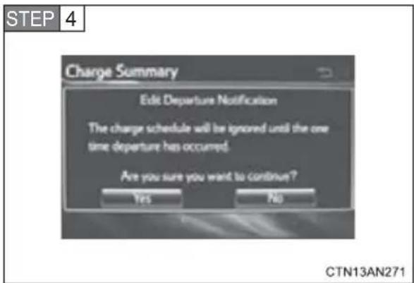
Touch "Yes".
Changing the charging schedule.
For details on changing the charging schedule, refer to Step 2 of one time departure. (→P. 70)
■When leaving the vehicle
To prevent vehicle theft and to increase the efficiency of pre-climate operation, check that all windows are closed.
■ Amount of time required for charging
The amount of time required to fully charge the traction battery varies according to a number of factors, such as the amount of charge remaining in the traction battery, the power source being used, the charge settings, ambient temperature, battery temperature and so forth.
Only use the following times as a guide to estimate charging time. The estimated times are to fully charge a completely discharged battery in normal charge mode or extended charge mode.
| Charge specification (Amps/Voltage) | Charging time*1 (hours) | |
| Normal charge mode | Extended charge mode | |
| 40 A/240 V 5 6 | ||
| 30 A/240 V 6.5 8 | ||
| 16 A/240 V 12 15 | ||
| 12 A/120 V*2 | 44 52 | |
*1: Charging time will vary with ambient temperature.
*2: Toyota supplied charging cable at time of purchase
Because a 240 V power source charges more quickly than a 120 V power source, Toyota recommends charging at 240 V.
■ Automatic OFF function when the charging cable is connected
If the charging cable is connected while the EV system is on, the EV system is automatically turned off.
■Default charge mode setting
The factory default setting is normal charge mode.
Charge mode setting
The charge mode will remain in the last charge mode selected for the next time charging is performed.
During charging
●The surface of the CCID (Charging Circuit Interrupting Device) may become hot, but this does not indicate a malfunction.
● Depending on radio wave conditions, interference may be heard on the radio.
■If charging has been interrupted
If charging is interrupted before the traction battery is fully charged (before both charging indicator lights illuminate), the EV system cannot be started and the shift position cannot be shifted from P for approximately 6 seconds. Start the EV system after 6 seconds have elapsed.
■ Charging time may increase
In the following situations, charging time may become longer than normal:
● In very hot or very cold temperatures.
●The vehicle is consuming a lot of electricity, for example, when pre-climate is used.
●There is a power outage during charging.
●There is an interruption in the electrical supply.
- There is a drop in the voltage of your panel's AC supply.
●The charge in the 12-volt battery is low, for example due to the vehicle being left unused for a long period of time.
■ Capacity reduction of the traction battery
The capacity of the traction battery will decline gradually with normal use over the life of the vehicle. The rate at which it declines is dependant on a number of factors, including environmental conditions and the way the vehicle is used. By observing the following precautions, battery capacity decline can be suppressed.
- Avoid parking the vehicle for prolonged periods in areas with a high temperature under direct sunlight when the traction battery is fully charged. When storing the vehicle for prolonged periods, it is recommended to park the vehicle in a shaded area or a cool garage. This helps minimize traction battery capacity decline.
- When not driving long distances, it is recommended to charge using normal charge mode to help minimize traction battery capacity decline. (→P. 58, 72)
● Regular use of the scheduled charging function helps mitigate battery capacity decline by avoiding storage at high SOC.
■When not using the vehicle for an extended period of time
In order to preserve the traction battery, Toyota recommends plugging in the vehicle whenever it is not in use.
Pre-climate operations will occur while the amount of charge remaining in the traction battery is more than 50% at the time pre-climate operations begin. If the schedule is left set, pre-climate operations will continue to function up to the maximum of 15 minutes even if the vehicle is not used for extended periods of time. Because this uses energy from the traction battery, temporarily suspend the pre-climate schedule (smart phone exclusive setting →P. 58) or delete the pre-climate schedule, if the vehicle is not being regularly used.
When using navigation screen operations, only canceling the schedule is available. Because the schedule will need to be set once again when it is used next time, Toyota recommends using a smart phone and temporarily suspending the schedule.
If the amount of charge remaining in the traction battery becomes low while driving
The driving power restriction output control warning light illuminates and driving range is extended by automatically restricting driving power and air conditioning system operations. Using the navigation system, promptly search for the closest charging station and charge the vehicle. If the traction battery fully discharges, driving will not be possible.
For information on how to search for a charging station, refer to the “Navigation System Owner's Manual”.
- Charging schedule confirmation display after switching the EV system off
The current charging schedule will be displayed for a while after the EV system is turned off. To change the charging schedule, set the schedule using the navigation system's screen. ( P. 64, 70)
■If the charging port door is frozen
→P. 268
■Pre-climate operations automatic shut-off
Pre-climate will automatically shut off under the following conditions:
●After about 15 minutes have passed since operations began
- If any one of the operating conditions are not met
- If there is only a slight difference between the air conditioning set temperature and the inside temperature.
- When a door is opened.
■While pre-climate is operating
●The effectiveness of the pre-climate operations may differ according to outside temperature. Pre-climate operations may be unable to reach the set temperature during very cold or very hot weather.
● Sometimes during normal operation of the pre-climate schedule, the electric fan may spin and an operating noise may be heard. However, this does not indicate a malfunction.
■Safety functions
- For safety purposes, the EV system cannot be started while the charging cable is connected to the vehicle, even if the “POWER” switch is operated. (→P. 443)
- If the charging cable is connected while the “READY” indicator light is illuminated, the EV system will stop automatically and driving will not be possible. (→P. 443)
- When the charging cable is connected to the vehicle, the shift position cannot be shifted out of P.
- For safety reasons, even if the charging cable is connected, charging will not start while the latch release button is being pressed.
However, if the latch release button is pressed and held for a few seconds or more while charging, charging will be canceled. To recommence charging, reinsert the charging cable.
If charging has not been carried out in a long time
The charging port cap's lever may get stuck and not open automatically even if the knob is moved. If this occurs, push aside the release button and open the cap by hand.
■When the outside temperature is low or high
The level shown on the SOC gauge ( P. 218) may drop slightly when the "POWER" switch is turned to ON mode, even if charging has been completed and the traction battery is fully charged. However, this does not indicate a malfunction.
■ Charging in extremely cold temperatures
If the vehicle is parked in ambient temperatures below freezing, 240 V charging is recommended.
If only a 120 V outlet is available, the following will improve your charge process:
●Charge at mid-day (when it is warmest)
●Protect the vehicle from wind during charging.
If the vehicle is still too cold to charge, please contact your Toyota dealership or tow it to a warmer charging location.
■Handling the traction battery
→P.22

CAUTION
When charging
- When charging the vehicle, make sure you observe the following precautions. Failure to do so can cause a fire or electric shock that may result in death or serious injury.
- Check that the electrical receptacle, charging cable and charging port do not have any damage.
- Check that charging cable plug's prongs are not bent.
- Check that the charging cable plug prongs are not dirty from dust and so forth.
- Insert the charging cable plug all the way into the electrical receptacle.
- Do not use an electrical receptacle that leaves the charging cable plug unstable after being inserted, such as an electrical receptacle that is in an extremely high location.
- Do not perform charging with the charging cable bundled or coiled.
- Check that the charging cable is not bent or underneath any heavy objects.
- Use a hook or mounting bracket to support the charging cable, so that it is not supported by the AC 120 V electrical receptacle.
- Use a dedicated AC 120 V electrical receptacle (NEMA 5-15R or NEMA 5-20R).

CAUTION
- When charging the vehicle, make sure you observe the following precautions. Failure to do so can cause an electric shock that may result in death or serious injury.
- Check that the electrical receptacle, charging cable and charging port do not have any areas that are damaged.
- Check that there is no snow or ice in the charging port
- Check that no water has built up in the charging port
- Do not plug in or unplug the charging cable plug with wet hands. Also, do not get the charging cable plug or electrical receptacle wet.
- Do not touch the charging connector's end terminals or short them with foreign objects.
- When the charging cable is not in use, store it in a location free from moisture.
- Do not pull, twist or bend the charging cable.
- Do not touch the charging port's end terminals with sharp metallic objects, such as wire, needles, and so forth.
- When charging outdoors, make sure to connect to an appropriate outdoor receptacle with a "While-in-use" cover.
Also, if rain falls during charging, take care that rainwater does not run along the length of cable and wet the electrical receptacle.
- If the electrical receptacle is submerged in water or covered in snow, do not insert the charging cable's plug. If, in this situation, the charging cable plug is already plugged in and needs to be unplugged, first turn off the breaker and then unplug the charging cable plug.
- To stop vehicle charging or if charging has been interrupted, disconnect the charging connector from the vehicle first, before unplugging the charging cable plug form the receptacle.
- Do not charge the vehicle during weather that may produce lightning.
- If you hear thunder while charging the vehicle, turn the breaker off without touching the vehicle or charging cable.

CAUTION
■Precautions for the pre-climate
Do not use pre-climate if people are in the vehicle.
Even when pre-climate is used, the temperature inside the vehicle may become very high or very low due to features such as the automatic shut-off. Do not leave children and/or pets inside the vehicle.
- When in the sun, the temperature inside a vehicle with all its windows closed may rise rapidly, possibly causing heat stroke or dehydration.
- When in cold weather, the temperature inside the vehicle may drop rapidly, possibly causing hypothermia.
Both of the above cases can lead to a serious health hazard or even death.
■Handling the traction battery
No part of the traction battery can be repaired by you or a non-Toyota technician. Never open the traction battery or perform any modifications to it. If you find a malfunction with the battery, always contact your Toyota dealer.
If the error warning indicator on the CCID (Charging Circuit Interrupting Device) stays on during charging
Press the reset button on the CCID (Charging Circuit Interrupting Device) ( P. 91). If the error warning indicator does not turn off even when the reset button is pressed, an electrical leakage may be occurring in the path to the power source, or there may be a problem with the charging cable or the charging system. In this event, stop charging immediately, remove the charging cable and contact your Toyota dealer. An accident may occur or damage may be inflicted if charging continues.
■When the charging cable is connected to the vehicle
Do not operate the shift lever.
In the unlikely event that the charging cable has been damaged, the shift position may change from P to another position and the vehicle could move, possibly leading to an accident.

NOTICE
■After charging
● After disconnecting the charging connector from the charging port, always make sure to firmly lock the charging port cap by closing it until a click is heard, and close the charging port door.
If the charging port cap or door is left open, water or foreign objects may enter the charging port, which could lead to vehicle damage.
- Promptly unplug the charging cable plug from the electrical receptacle and store the charging cable in a dry, clean place. The charging cable may be damaged if stepped on.
■ Using private power generators
Do not use private power generators as a power source for charging. Doing so may make charging unsafe.
■ Usable temperature range
- Do not charge if the outside temperature is below -22 °F (-30 °C), as it is likely that charging will take longer, and equipment related to charging may be damaged.
- Do not leave the vehicle or the charging cable in areas where the outside temperature is lower than -40 °F (-40 °C). The vehicle or charging cable may be damaged.
If charging does not commence even though the correct procedure has been carried out, and an error message is shown on the multi-information display, try the correction procedures listed in the table below.
If you still cannot correct the problem, contact your Toyota dealer.
A problem has occurred during charging
Refer to the following table and carry out the appropriate correction procedure.
| Situation Reason | Correction procedure | |
| The power indicator on the CCID (Charging Circuit Interrupting Device) does not illuminate even when connected to a power source | The plug is not properly connected to the electrical receptacle. | Insert the plug firmly into the electrical receptacle. |
| There is a power outage. | Restart charging once power has been restored. | |
| The circuit breaker has activated. | Check the circuit breaker. If there is nothing unusual, connect to another electrical receptacle and check that charging is possible.If charging is possible, there is likely a problem with the first electrical receptacle.Contact your building manager or an electrician. | |
| The power indicator on the CCID (Charging Circuit Interrupting Device) does not illuminate even when connected to a power source | The charging cable connecting the CCID (Charging Circuit Interrupting Device) to the plug is damaged. | Stop charging immediately and contact your Toyota dealer. |
| The error warning indicator on the CCID (Charging Circuit Interrupting Device) illuminates | The electrical leakage detection function or the self-test function has operated and the power supply has been interrupted. | Reset the CCID (Charging Circuit Interrupting Device). (→P. 91) |
| The charging indicator lights do not illuminate or flash even though the charging connector is connected | The latch release button is being pressed. | For safety purposes, charging will be interrupted when the latch release button is pressed. (→P. 82) When connecting the charging connector to the vehicle, insert it into the charging port without pressing the latch release button. |
| The charging connector is not properly connected to the charging port. | Check that the charging connector is firmly connected to the charging port. If the charging indicator lights do not illuminate or flash even though the charging connector is firmly connected, there may be a problem in the system. Stop charging immediately and consult your Toyota dealer. | |
| The charging indicator lights do not illuminate or flash even though the charging connector is connected | The traction battery is already fully charged. | — |
| If the charging indicator lights flash quickly | An error may have occurred in the charging system. | Turn the “POWER” switch to ON mode and comply with the warning message shown on the multi-information display. (→P. 443) |
If a warning message is displayed after charging
If a warning message is displayed when the “POWER” switch is turned to ON mode after charging, comply with the contents of the message and take any necessary actions. ( P. 443)
■ Resetting the CCID (Charging Circuit Interrupting Device)
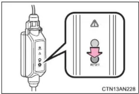
If the error warning indicator of the CCID (Charging Circuit Interrupting Device) illuminates during charging, conduct either of the following procedures.
- Press the reset button on the CCID (Charging Circuit Interrupting Device).
- Disconnect the plug, wait for a short while and reconnect.
The error warning indicator will go out and the power source will reconnect.
- If the error warning indicator does not illuminate a second time after the power source has been reconnected, charging can continue.
- If the error warning indicator illuminates again, there may be a problem with the charging cable or the power source. Stop charging immediately and contact your Toyota dealer.
For safety, inspect the charging cable on a routine basis (at least once a month).
Inspecting the electrical leakage detection function
Check that the electrical leakage detection function operates properly by following the procedure below.
In the unlikely event that the electrical leakage detection function does not operate properly, contact your Toyota dealer as soon as possible.
STEP 1 Insert the charging cable into the electrical receptacle of the external power source.
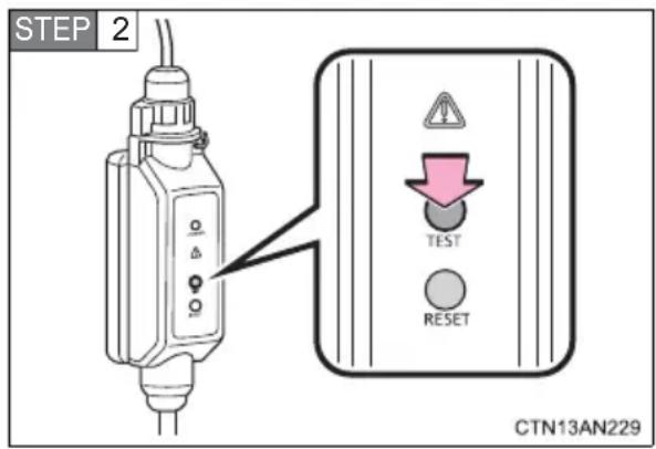
Press the test button on the CCID (Charging Circuit Interrupting Device).
If the error warning indicator illuminates when the test button is pressed, the function is operating correctly.
STEP 3 Press the reset button on the CCID (Charging Circuit Interrupting Device).
Turn off the error warning indicator. Charging cannot be carried out while the error warning indicator is illuminated.
Charging can be continued by following the normal procedure. If not charging, store the charging cable.

CAUTION
■Routine inspection
Check the following points regularly.
If use is continued without inspection, fire or electric shock may occur, possibly resulting in death or serious injury.
● The charging cable, plug, charging connector, CCID (Charging Circuit Interrupting Device) etc. have not been damaged
●The electrical receptacle has not been damaged
●The plug does not get extremely hot during use
●The tip of the plug has not been deformed
●The plug is not dirtied by dust etc.
Inspect the plug after removing it from the electrical receptacle.
■Maintaining the charging cable
When the cable is dirty, first remove the dirt with a squeezed out cloth, and then wipe the cable with a dry cloth. Do not wash with water, as doing so could cause a fire or electrical shock when charging, which could lead to death or serious injury.
■When not using the charging cable for a long time
Remove the plug from the electrical receptacle. Dust could accumulate on the plug or in the electrical receptacle, possibly causing overheating which could lead to a fire.
Also, keep the cable in a place free from moisture.
The following keys are provided with the vehicle.
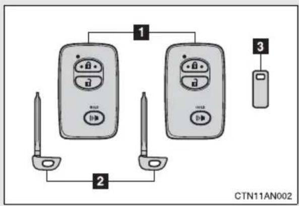
flowchart
graph TD
    A["Device 1"] --> B["Device 2"]
    C["Device 2"] --> D["Device 3"]
    B --> E["Device 1"]
    D --> F["Device 3"]
1 Electronic keys
- Operating the smart key system ( P. 96)
- Operating the wireless remote control function (→P. 108)
2 Mechanical keys
3 Key number plate
Using the mechanical key
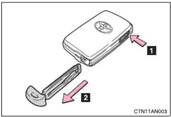
To take out the mechanical key, push the release button and take the key out.
After using the mechanical key, store it in the electronic key. Carry the mechanical key together with the electronic key. If the electronic key battery is depleted or the entry function does not operate properly, you will need the mechanical key.
$$ (\rightarrow \mathrm{P}. 4 6 8) $$
■ When required to leave a key to the vehicle with a parking attendant
Lock the glove box as circumstances demand. ( P. 297)
Remove the mechanical key for your own use and provide the attendant with the electronic key only.
■Key number plate
Keep the plate in a safe place such as your wallet, not in the vehicle. In the event that a key is lost, a new key can be made by your Toyota dealer using the key number plate. ( P. 467)
■When riding in an aircraft
When bringing a key with wireless remote control function onto an aircraft, make sure you do not press any buttons on the key while inside the aircraft cabin. If you are carrying the key in your bag etc, ensure that the buttons are not likely to be pressed accidentally. Pressing a button may cause the key to emit radio waves that could interfere with the operation of the aircraft.

NOTICE
■To prevent key damage
- Do not subject the keys to strong shocks, expose them to high temperatures by placing them in direct sunlight, or get them wet.
- Do not expose the keys to electromagnetic materials or attach any material that blocks electromagnetic waves to the key surface.
- Do not disassemble the key.
The following operations can be performed simply by carrying the electronic key on your person, for example in your pocket.
(The driver should always carry the electronic key.)
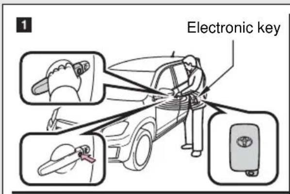
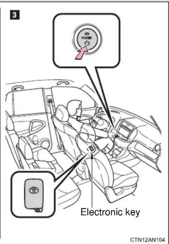
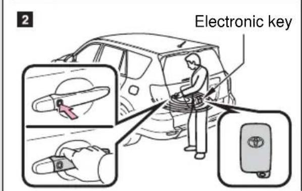
1 Locks and unlocks the doors ( P. 97)
2 Locks and unlocks the back door ( P. 97)
3 Starts the EV system ( P. 200)
Unlocking and locking the doors and back door (front and back door handles only)
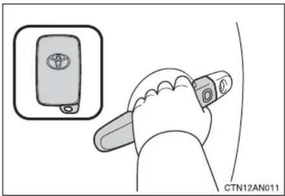
Grip the driver's door handle to unlock the door. Grip the passenger's door handle to unlock all the doors.*
Make sure to touch the sensor on the back of the handle.
The doors cannot be unlocked for 3 seconds after the doors are locked.
*: The door unlock settings can be changed. (→P. 103)
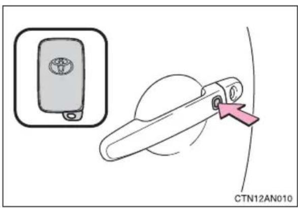
Press the lock button to lock the doors.
Antenna location and effective range
Antenna location
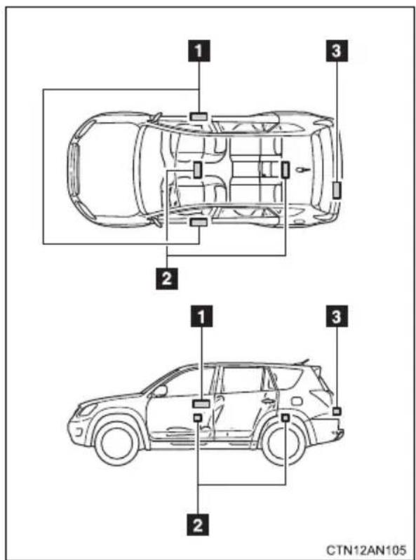
1 Antennas outside the cabin
2 Antennas inside the cabin
3 Antenna outside the luggage compartment
■Effective range (areas within which the electronic key is detected)
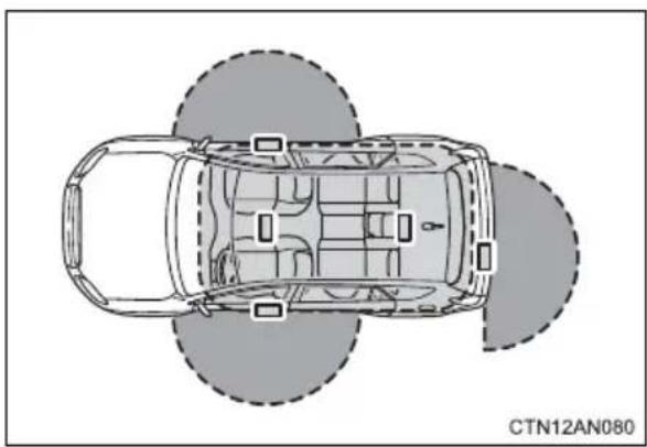
natural_image
Top-down schematic of a car showing front, rear, and side views with no text or symbolsWhen locking or unlocking the doors
The system can be operated when the electronic key is within about 2.3 ft. (0.7 m) of either of the outside front door handles and back door handle.
When starting the EV system or changing "POWER" switch modes
The system can be operated when the electronic key is inside the vehicle.
Operation signals
A buzzer sounds and the emergency flashers flash to indicate that the doors have been locked/unlocked. (Locked: Once; Unlocked: Twice)
■Alarms and warning indicators
A combination of exterior and interior alarms are used to prevent theft of the vehicle and unforeseeable accidents resulting from erroneous operation. Take appropriate measures according to the warning message shown on the multi-information display. ( P. 427)
The following table describes circumstances and correction procedures when only alarms are sounded.
| Alarm Situation Correction procedure | ||
| Interior alarm pings once and exterior alarm sounds once for 10 seconds*1 | An attempt was made to lock the doors using the entry function while the electronic key was still inside the passenger compartment. | Retrieve the electronic key from the passenger compartment and lock the doors again. |
| An attempt was made to exit the vehicle and lock the doors without first turning the “POWER” switch off. | Turn the “POWER” switch off and lock the doors again. | |
| Exterior alarm sounds once for 10 seconds | An attempt was made to lock the vehicle while a door is open. | Close all of the doors and lock the doors again. |
| Interior alarm pings continuously*1 | The “POWER” switch was turned to ACCESSORY mode while the driver's door was open (or the driver's door was opened while the “POWER” switch was in ACCESSORY mode). | Turn the “POWER” switch off and close the driver's door. |
| Interior alarm sounds continuously*1 | When the “POWER” switch was in ON or ACCESSORY mode, an attempt was made to open the door and exit the vehicle when the shift position was not in P. | Push the P position switch and turn the “POWER” switch off. |
| Interior and exterior alarms sound continuously*1 | When the “POWER” switch was in ON or ACCESSORY mode, the driver's door was closed after the key was carried outside the vehicle when the shift position was not in P. | Push the P position switch, turn the “POWER” switch off and close the driver's door again. |
| Interior alarm pings once*1 | The electronic key has a low battery. | Replace the electronic key battery. |
| An attempt was made to start the EV system without the electronic key being present, or the electronic key was not functioning normally. | Start the EV system with the electronic key present.*2 | |
| Interior alarm pings once and exterior alarm sounds 3 times*1 | The driver's door was closed after the key was carried outside the vehicle when the “POWER” switch was not turned off. | Turn the “POWER” switch OFF and close the driver's door again. |
| An occupant carried the electronic key outside the vehicle and closed the door while the “POWER” switch was not off. | Bring the electronic key back into the vehicle. | |
*1: A message will be shown on the multi-information display in the instrument cluster.
^*2 : If the EV system does not start when the electronic key is inside the vehicle, the electronic key battery may be depleted or there may be difficulties receiving the signal from the key. ( P. 468)
■Security feature
If a door is not opened within approximately 60 seconds after the vehicle is unlocked, the security feature automatically locks the vehicle again.
■Switching the door unlock function
It is possible to set which doors the entry function unlocks.
STEP 1 Turn the "POWER" switch off.
STEP 2 When the indicator on the key surface is turned off, push and hold 🔒 or 🔒 approximately 5 seconds while pushing the button on the key.
The setting changes each time an operation is performed, as shown below. (When changing the setting continuously, release the buttons, wait for at least 5 seconds, and repeat STEP 2
| Multi-information display | Unlocking doors Beep | |
 | Hold the driver's door handle to unlock only the driver's door. | Exterior: Beeps three timesInterior: Pings once |
| Hold the passenger's door handle or back door opener to unlock all the doors. | ||
 | Hold a front door handle or back door opener to unlock all the doors. | Exterior: Beeps twiceInterior: Pings once |
■Battery-saving function
In the following circumstances, the entry function is disabled in order to prevent the 12-volt battery from discharging and the electronic key battery from depleting.
- When the entry function has not been used for 2 weeks or more.
- When the electronic key has been left within approximately 3 ft. (1 m) of the vehicle for 10 minutes or more.
The system will resume operation when
●The vehicle is locked using the door handle lock switch when carrying the electronic key on your person.
●The vehicle is locked/unlocked using the wireless remote control. (→P. 108)
● The vehicle is locked/unlocked using the mechanical key. (→P. 468)
■Conditions affecting operation
The smart key system uses weak radio waves. In the following situations, the communication between the electronic key and the vehicle may be affected, preventing the smart key system and wireless remote control from operating properly. (Ways of coping: →P. 468)
- When the electronic key battery is depleted
●Near a TV tower, electric power plant, gas station, radio station, large display, airport or other facility that generates strong radio waves or electrical noise - When carrying a portable radio, cellular phone, cordless phone or other wireless communication devices
- When the electronic key is in contact with, or is covered by a metallic object
- When multiple electronic keys are in the vicinity
- When carrying or using the electronic key together with one or move of the following devices that emit radio waves
- Another vehicle's electronic key
- A wireless key that emits radio waves
- Personal computer
- If window tint with a metallic content or metallic objects is attached to the rear window
■Note for the entry function
●Even when the electronic key is within the effective range (detection areas), the system may not operate properly in the following cases.
- The electronic key is too close to the window or outside door handle, near the ground, or in a high place when the doors are locked or unlocked.
- The electronic key is on the instrument panel, in the auxiliary box, on the floor or in the glove box when the EV system is started or "POWER" switch modes are changed.
- Do not leave the electronic key on top of the instrument panel or near the door pockets when exiting the vehicle. Depending on the radio wave reception conditions, it may be detected by the antenna outside the cabin and the door will become lockable from the outside, possibly trapping the electronic key inside the vehicle.
- As long as the electronic key is within the effective range, the doors may be locked or unlocked by anyone.
● Even if the electronic key is not inside the vehicle, it may be possible to start the EV system if the electronic key is near the window.
●The doors may unlock if a large amount of water splashes on the door handle, such as in the rain or in a car wash. (The doors will automatically be locked after approximately 60 seconds if the doors are not opened and closed.)
●Gripping the door handle when wearing a glove may not unlock the door. - If the wireless remote control is used to lock the doors when the electronic key is near the vehicle, there is a possibility that the door may not be unlocked by the entry function. (Use the wireless remote control to unlock the doors.)
■ When the vehicle is not driven for extended periods
To prevent theft of the vehicle, do not leave the electronic key within 6 ft. (2 m) of the vehicle.
■To operate the system properly
Make sure to carry the electronic key when operating the system. Do not get the electronic key too close to the vehicle when operating the system from the outside of the vehicle.
Depending on the position and holding condition of the electronic key, the key may not be detected correctly and the system may not operate properly. (The alarm may go off accidentally, or the door lock prevention may not function.)
If the smart key system does not operate properly
- Locking and unlocking the doors: Use the mechanical key. (→P. 468)
● Starting the EV system. ( P. 468)
Electronic key battery depletion
- The standard battery life is 1 to 2 years. (The battery becomes depleted even if the electronic key is not used.) If the smart key system or the wireless remote control function does not operate, or the detection area becomes smaller, the battery may be depleted. Replace the battery when necessary. ( P.383)
- If the battery becomes low, an alarm will sound in the cabin when the EV system stops. (→P. 100)
● To avoid serious deterioration, do not leave the electronic key within 3 ft. (1 m) of the following electrical appliances that produce a magnetic field:
• TVs
- Personal computers
- Cellular phones, cordless phones and battery chargers
- Recharging cellular phones or cordless phones
- Induction cookers
- Table lamps
■When the electronic key battery is fully depleted
→P. 383
■ Customization that can be configured at Toyota dealer
Settings (e. g. smart key system) can be changed.
(Customizable features → P. 500)
■Certification for the smart key system
FCC ID: HYQ14AEM
FCC ID: NI4TMLF-2
FCC ID: HYQ14AAB
FCC ID: HYQ13BZS
FCC ID: HYQ14ABK
FCC ID: HYQ13CZA
NOTE:
This device complies with Part 15 of the FCC Rules. Operation is subject to the following two conditions: (1) this device may not cause harmful interference, and (2) this device must accept any interference received, including interference that may cause undesired operation.
FCC WARNING:
Changes or modifications not expressly approved by the party responsible for compliance could void the user's authority to operate the equipment.

CAUTION
■ Caution regarding interference with electronic devices
● People with implanted pacemakers or cardiac defibrillators should keep away from smart key system antennas. (→P. 98) The radio waves may affect the operation of such devices. If necessary, the entry function can be disabled. Ask your Toyota dealer for details, such as the frequency of radio waves and timing of emitting the radio waves. Then, consult your doctor to see if you should disable the entry function.
- Users of any electrical medical device other than implanted pacemakers and implanted cardiac defibrillators should consult the manufacturer of the device for information about its operation under the influence of radio waves.
Radio waves could have unexpected effects on the operation of such medical devices.
Ask your Toyota dealer for details for disabling the entry function.
The wireless remote control can be used to lock and unlock the vehicle from outside the vehicle.
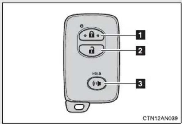
1 Locks all doors
2 Unlocks all doors
Pressing the button unlocks the driver's door. Pressing the button again within 3 seconds unlocks the other doors.
3 Pushing and holding: Sounds the alarm
Operation signals
A buzzer sounds and the emergency flashers flash to indicate that the doors have been locked/unlocked. (Locked: Once; Unlocked: Twice)
■Panic mode
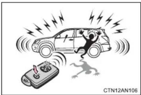
natural_image
Illustration of a person falling into a car with lightning bolts and a switch, symbolizing accident or damage (no text or symbols present)When (is) pushed for longer than about one second, an alarm will sound for about 60 seconds and the vehicle lights will flash to deter any person from trying to break into or damage your vehicle.
To stop the alarm, push any button on the wireless remote control.
■Door lock buzzer
If a door is not fully closed, a buzzer sounds continuously if an attempt to lock the door is made. Fully close the door to stop the buzzer, and lock the vehicle once more.
■Key battery depletion
→P. 383
If the wireless remote control does not operate
Locking and unlocking the doors: Use the mechanical key. ( P. 468)
■Security feature
If a door is not opened within approximately 60 seconds after the vehicle is unlocked, the anti-theft system automatically locks the vehicle again.
■Conditions affecting operation
→P. 104
■ Customization that can be configured at your Toyota dealer
Settings (e.g. wireless remote control) can be changed. (Customizable features → P. 500)
■Certification for wireless remote control
→P. 107
1-5. Opening, closing and locking the doors
Side doors
The vehicle can be locked and unlocked using the entry function, wireless remote control or door lock switch.
Entry function
→P.96
■ Wireless remote control
→P. 108
■Door lock switch
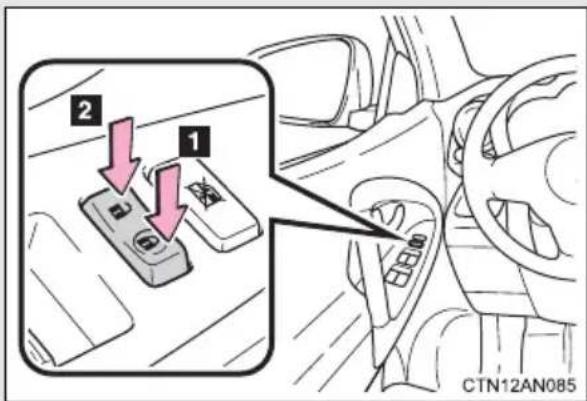
1 Locks all the doors
2 Unlocks all the doors
Inside lock buttons
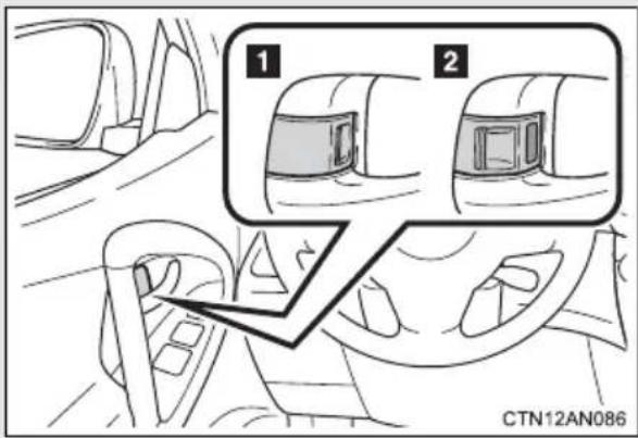
Pulling the door handle can open the front door even if the lock button is in the lock position.
Locking the front doors from the outside without the wireless remote control or key
STEP 1 Move the inside lock button to the lock position.
STEP 2 Close the door.
The door cannot be locked if the "POWER" switch is in ACCESSORY or ON mode, or the electronic key is left inside the vehicle.
The key may not be detected correctly and the door may be locked.
Rear door child-protector lock
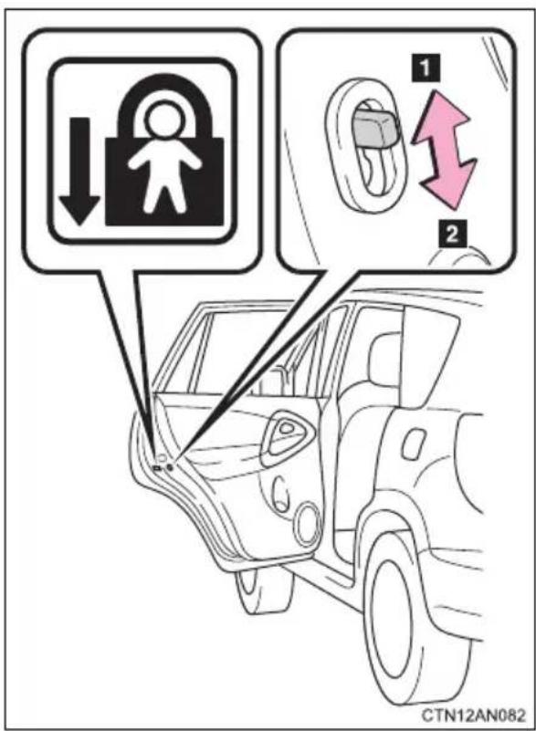
The door cannot be opened from inside the vehicle when the lock is set.
1 Unlock
2 Lock
These locks can be set to prevent children from opening the rear doors. Push down on each rear door switch to lock both rear doors.
■ Using the mechanical key
The doors can also be locked and unlocked with the mechanical key. ( P. 468)
- When all the doors are locked with the entry function, wireless remote control or key
The doors cannot be unlocked with the door lock switch.
The door lock switch can be reset by unlocking all the doors with the entry function, wireless remote control or key.
■The doors cannot be locked when
The “POWER” switch is in ACCESSORY or ON mode, or the electronic key is left inside the vehicle.
Depending on the position of the electronic key, the key may not be detected correctly and the door may be locked.
■ Customization that can be configured at Toyota dealer
Settings (e.g. door unlocking function) can be changed.
(Customizable features → P. 500)

CAUTION
■To prevent an accident
Observe the following precautions while driving the vehicle.
Failure to do so may result in a door opening and an occupant falling out, resulting in death or serious injury.
●Always use a seat belt.
●Always lock all the doors.
●Ensure that all doors are properly closed.
- Do not pull the inside handle of the doors while driving.
The doors may be opened and the passengers are thrown out of the vehicle and it may result in serious injury or death.
Be especially careful for the front doors, as the doors may be opened even if the inside lock buttons are in locked position.
- Set the rear door child-protector locks when children are seated in the rear seats.
1-5. Opening, closing and locking the doors
Back door
The back door can be opened using the back door handle. The back door can be locked and unlocked using the wireless remote control, entry function or door lock switch.
■Locking and unlocking the back door
Entry function
→P. 97
Wireless remote control
→P. 108
Door lock switch
→P. 110
Rear step bumper
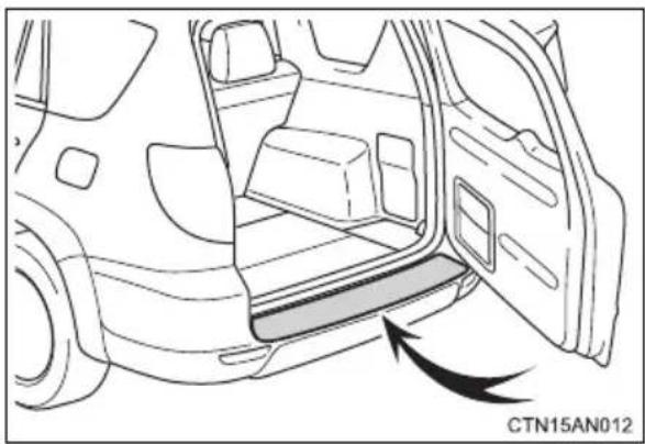
natural_image
Diagram of a car interior showing the door, seat, and side panel with an arrow indicating direction (no text or symbols)The rear step bumper is intended for rear end protection and easier step-up loading.
Luggage compartment light
The luggage compartment lights turn on when the back door is opened with the luggage compartment light switch on.
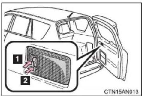
1 On
2 Off
■ Customization that can be configured at Toyota dealer
Settings (e.g. wireless remote control) can be changed.
(Customizable features → P. 500)

CAUTION
■Caution while driving
- Keep the back door closed while driving.
If the back door is left open, it may hit near-by objects while driving or luggage may be unexpectedly thrown out, causing an accident.
●Before driving the vehicle, make sure that the back door is fully closed. If the back door is not fully closed, it may open unexpectedly while driving, causing an accident.
●Never let anyone sit in the luggage compartment. In the event of sudden braking or a collision, they are susceptible to death or serious injury. - Do not get on the rear step bumper.
■Caution while parking
If the open back door hides the stop, tail or rear turn signal lights, other road users must be warned of the presence of your vehicle by a warning triangle or other device.
■When children are in the vehicle
Observe the following precautions.
Failure to do so may result in death or serious injury.
- Do not allow children to play in the luggage compartment.
If a child is accidentally locked in the luggage compartment, they could have heat exhaustion or other injuries. - Do not allow a child to open or close the back door.
Doing so may cause the back door to move unexpectedly, or cause the child's hands, head, or neck to be caught by the closing back door.

CAUTION
■Operating the back door
Observe the following precautions.
Failure to do so may cause parts of the body to be caught, resulting in death or serious injury.
- When opening or closing the back door, thoroughly check to make sure the surrounding area is safe.
- If anyone is in the vicinity, make sure they are safe and let them know that the back door is about to open or close.
- Use caution when opening or closing the back door in windy weather as it may move abruptly in strong wind.
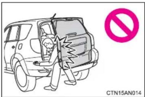
●The back door may close if it is not opened fully. It is more difficult to open or close the back door on an incline than on a level surface, so beware of the back door unexpectedly opening or closing by itself. Make sure that the back door is fully open and secure before using the luggage compartment.
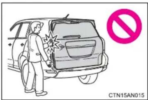
- When closing the back door, take extra care to prevent your fingers etc. from being caught.
-
When closing the back door, make sure to press it lightly on its outer surface.
-
Do not attach any accessories other than genuine Toyota parts to the back door. Such additional weight on the back door may interfere with the safety opening and closing operation of the back door.
- If the open back door hides the stop, tail, rear side marker or rear turn signal lights while you are parked, other road users must be warned of the presence of your vehicle by a warning triangle or other device.

NOTICE
■To prevent damage to the back door components
Do not allow more than one person to get on the rear step bumper at a time.
■To prevent 12-volt battery discharge
Do not leave the luggage compartment light on for extended periods while the EV system is off.
1-6. Adjustable components (seats, mirrors, steering wheel) Front seats
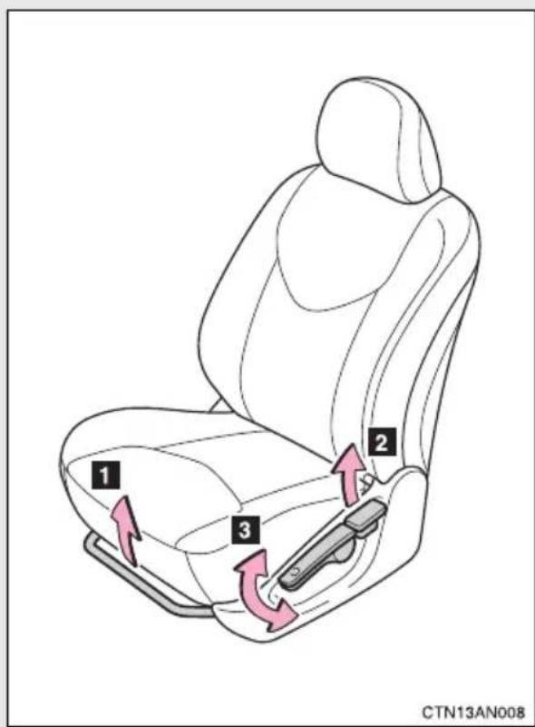
1 Seat position adjustment lever
2 Seatback angle adjustment lever
3 Vertical height adjustment lever (driver's side only)
Flattening the front seatbacks
■Before flattening the front seatbacks
Slide the rear seats as far back as possible. (→P. 121)
■Flattening the front seatbacks
STEP 1 Remove the front head restraint. ( P. 127)
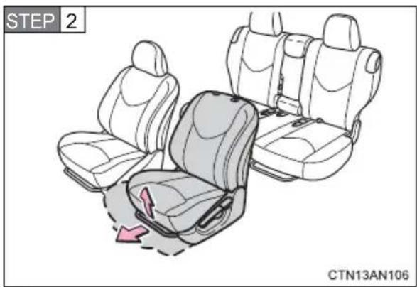
Slide the front seat further forward than the forward-most lockable position.
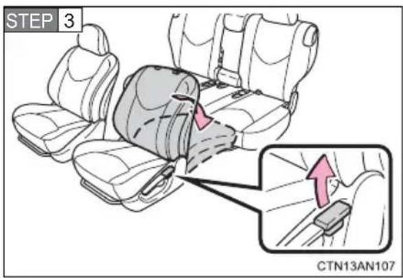
Pull the seatback angle adjustment lever up to unlock and push down the seatback.
After returning the seat to its original position, be certain to replace the head restraint.
Active head restraints
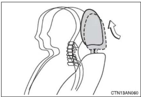
natural_image
Diagram of a human head with a medical device inserted, showing anatomical alignment and movement (no text or symbols)When the occupant's lower back presses against the seatback during a rear-end collision, the head restraint moves slightly forward and upward to help reduce the risk of whiplash on the seat occupant.
■Active head restraints
Even small forces applied to the seatback may cause the head restraint to move. Pushing up a locked head restraint forcibly may appear the head restraint inner structure. These do not indicate problems.
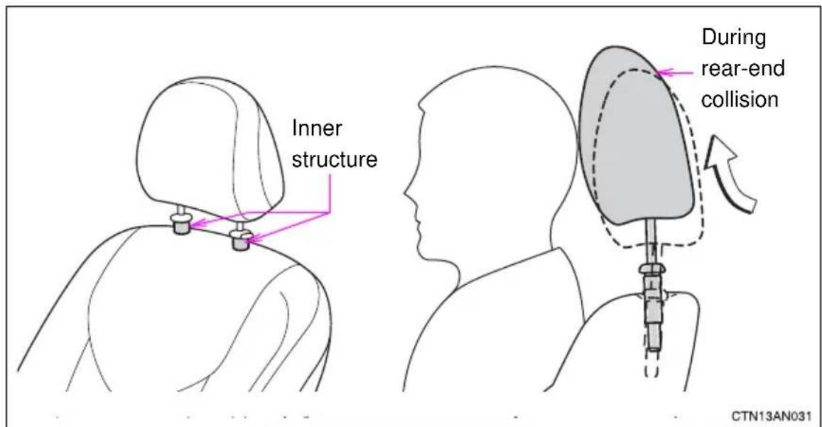

CAUTION
■Seat adjustment
● Be careful that the seat does not hit passengers or luggage.
●To reduce the risk of sliding under the lap belt during a collision, do not recline the seat more than necessary.
If the seat is too reclined, the lap belt may slide past the hips and apply restraint forces directly to the abdomen, or your neck may contact the shoulder belt, increasing the risk of death or serious injury in the event of an accident.
Adjustments should not be made while driving as the seat may unexpectedly move and cause the driver to lose control of the vehicle.
●After adjusting the seat, make sure that the seat is locked in position.
1-6. Adjustable components (seats, mirrors, steering wheel) Rear seats
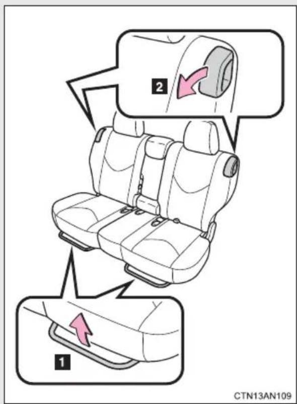
1 Seat position adjustment levers
2 Seatback angle adjustment levers
When a person sits in the rear center position, adjust both seat cushions to the same position and align all seat-backs at the same angle.
Folding down the rear seatbacks
Folding down the rear seats will enlarge the luggage compartment.
■Before folding down the rear seatbacks
STEP 1 Stow the rear center seat belt. (→P. 133)
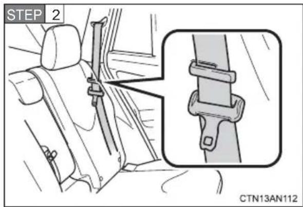
Make sure the outside seat belt passes through the hanger when folding the rear seat.
This prevents the shoulder belt from being damaged.
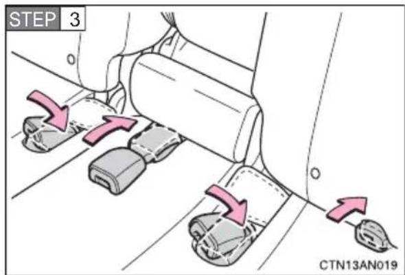
Stow the rear seat belt buckles.
STEP 4 Remove the outside head restraints ( P. 128)
STEP 5 Lower the rear center seat head restraint to the lowest position. (→P. 127)
STEP 6 Raise the armrest until it locks. ( P. 313)
■Folding down the rear seatbacks
STEP 1 Slide the rear seats as far back as possible. (→P. 121)
From inside
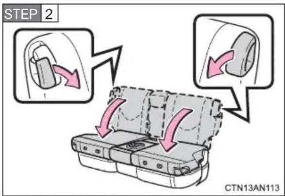
Pull down the seatback angle adjustment lever and fold down the seatback.
From outside
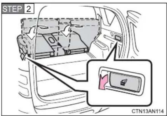
Open the back door and pull the lock release lever to fold down the rear seat.

CAUTION
■When folding the rear seatbacks down
Observe the following precautions. Failure to do so may result in death or serious injury.
●Do not fold the seatbacks down while driving.
- Stop the vehicle on level ground, set the parking brake and shift the shift position to P.
- Do not fold the rear seatback when passengers sit or luggage is placed on the seat.
- Do not allow passengers to ride on the folded seat or in the luggage compartment while driving.
● Make sure that no passengers or luggage are on the rear seats.
● Make sure the seatback is securely locked by pushing forward and rearward on the top of the seatback.
- Do not allow anyone to sit on a folded seatback or in the luggage compartment while driving.
- Do not allow children to enter the luggage compartment.

CAUTION
■Seat adjustment
Observe the following precautions.
Failure to do so may result in death or serious injuries.
● To reduce the risk of sliding under the lap belt during a collision, do not recline the seat more than necessary.
If the seat is too reclined, the lap belt may slide past the hips and apply restraint forces directly to the abdomen, or your neck may contact the shoulder belt, increasing the risk of death or serious injury in the event of an accident.
Adjustments should not be made while driving as the seat may unexpectedly move and cause the driver to lose control of the vehicle.
● Be careful not to get your hands or feet pinched in the seat.
- Do not adjust the seat while the vehicle is moving as the seat may unexpectedly move and cause the driver to lose control of the vehicle.
●Be careful that the seat does not hit a passenger or luggage.
- Do not put objects under the seats.
Otherwise, the objects may interfere with the seat-lock mechanism or unexpectedly push up the seat position adjustment lever and the seat may suddenly move, causing the driver to lose control of the vehicle.
- Adjust both seat cushions to the same position and align all seatbacks at the same angle when a person sits in the rear center position.
Otherwise, the person cannot wear the seat belt properly and this may cause death or serious injuries in a collision.
■After adjusting a seat
Observe the following precautions. Failure to do so may result in death or serious injury.
● Make sure the seat position and seatback are securely locked by pushing the seat and seatback forward and rearward.
- Check that the seat belts are not twisted or caught in the seatback.

NOTICE
■ Stowing the seat belts
The seat belts and the buckles must be stowed before you fold down the rear seatbacks.
1-6. Adjustable components (seats, mirrors, steering wheel) Head restraints
Head restraints are provided for all seats.
Front seats
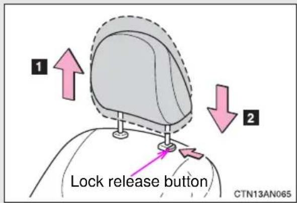
1 Up
Pull the head restraints up.
2 Down
Push the head restraint down while pushing the lock release button.
Rear center seat
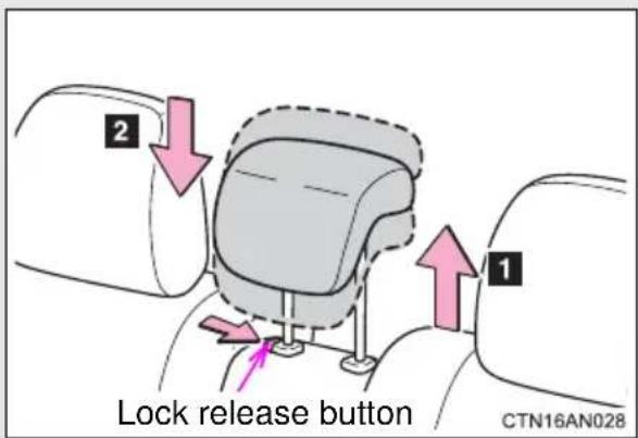
1 Up
Pull the head restraints up.
2 Down
Push the head restraint down while pushing the lock release button.
Rear outside seats
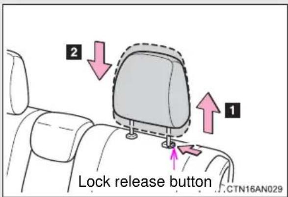
1 Up
2 Down
Pull up or push down the head restraint while pushing the lock release button.
■Removing the head restraints
Front seats
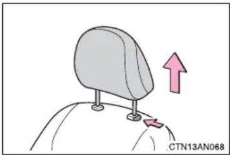
natural_image
Illustration of a car head with a pink upward arrow indicating motion or movement (no text or symbols)Pull the head restraint up while pushing the lock release button.
Rear seats
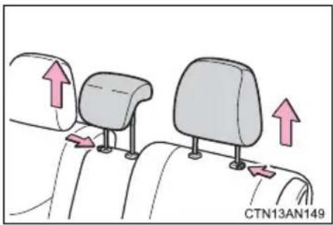
natural_image
Diagram of car seat mounting points with arrows indicating direction (no text or symbols)Pull the head restraint up while pushing the lock release button.
■Installing the head restraints
Front seats
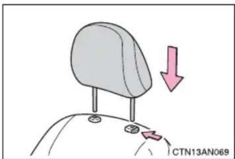
Rear seats
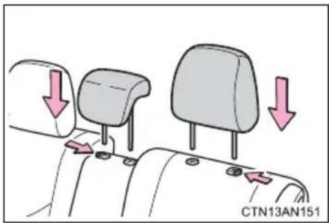
Align the head restraint with the installation holes and push it down to the lock position.
Press and hold the lock release button when lowering the head restraint.
Align the head restraint with the installation holes and push it down to the lock position.
Press and hold the lock release button when lowering the head restraint.
■Adjusting the height of the head restraints
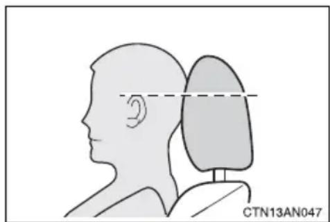
natural_image
Side profile illustration of a human head and neck with a dashed line indicating measurement or alignment (no text or symbols)Make sure that the head restraints are adjusted so that the center of the head restraint is closest to the top of your ears.
■Adjusting the rear center seat head restraint
Always raise the head restraint one level from the stowed position when using.

CAUTION
■Head restraint precautions
Observe the following precautions regarding the head restraints. Failure to do so may result in death or serious injury.
● Use the head restraints designed for each respective seat.
- Adjust the head restraints to the correct position at all times.
● After adjusting the head restraints, push down on them and make sure they are locked in position.
- Do not drive with the head restraints removed.
1-6. Adjustable components (seats, mirrors, steering wheel) Seat belts
Make sure that all occupants are wearing their seat belts before driving the vehicle.
■ Correct use of the seat belts
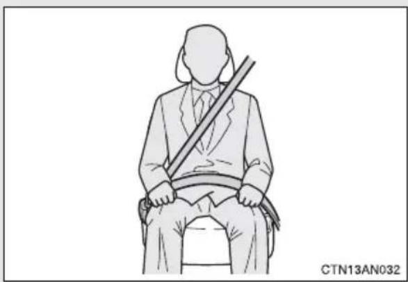
natural_image
Line drawing of a seated person holding a long object, no text or symbols present- Extend the shoulder belt so that it comes fully over the shoulder, but does not come into contact with the neck or slide off the shoulder.
●Position the lap belt as low as possible over the hips. - Adjust the position of the seatback. Sit up straight and well back in the seat.
●Do not twist the seat belt.
■Fastening and releasing the seat belt
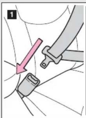
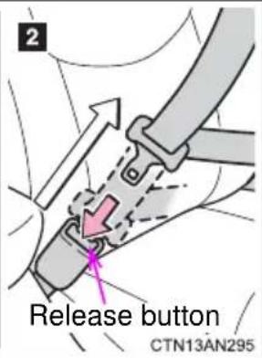
1 To fasten the seat belt, push the plate into the buckle until a click sound is heard.
2 To release the seat belt, press the release button.
■ Adjusting the seat belt shoulder anchor height (front seats)
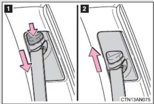
1 Push the seat belt shoulder anchor down while pressing the release button.
2 Push the seat belt shoulder anchor up.
Move the height adjuster up as needed until you hear a click.
Rear center seat belt
The rear center seat belt is a 3-point type restraint with 2 buckles. Both seat belt buckles must be correctly located and securely latched for proper operation.
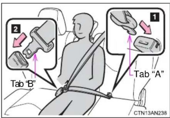
Make sure that the buckle 1 is securely latched ready for use of the center seat belt.
1 Tab "A"
2 Tab "B"
■Releasing method
The rear center seat belt can be completely released only when necessary such as when folding down the rear seats.
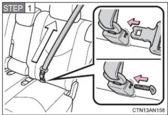
To release tab "A", insert tab "B" or the mechanical key ( P. 94) into the hole on the buckle.
Retract the belt slowly when releasing and stowing the seat belt.
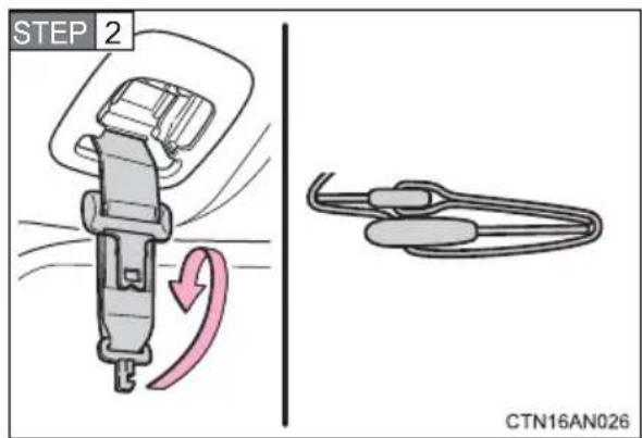
Fold the seat belt.
Fold the seat belt in a manner that places tabs "A" and "B" on top of each other, as shown in the illustration.
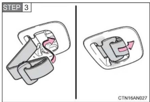
Stow the seat belt.
Make sure that the tabs are securely stowed inside the cover.
Seat belt pretensioners (front seats)
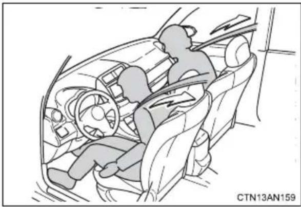
natural_image
Interior view of a car showing two people seated in the dashboard and steering wheel (no text or symbols visible)The pretensioner helps the seat belt to quickly restrain the occupant by retracting the seat belt when the vehicle is subjected to certain types of severe frontal collision or a vehicle rollover.
The pretensioner may not activate in the event of a minor frontal impact, a side impact or a rear impact.
Emergency locking retractor (ELR)
The retractor will lock the belt during a sudden stop or on impact. It may also lock if you lean forward too quickly. A slow, easy motion will allow the belt to extend so that you can move around fully.
■Automatic locking retractor (ALR)
When a passenger's shoulder belt is completely extended and then retracted even slightly, the belt is locked in that position and cannot be extended. This feature is used to hold the child restraint system (CRS) firmly. To free the belt again, fully retract the belt and then pull the belt out once more. (→P. 176)
■When not using the outer rear seat belts
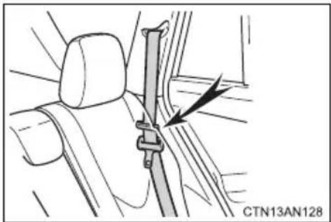
natural_image
Interior view of a car showing a seatbelt buckle and a black arrow pointing to the seat (no text or symbols)Pass the outer rear seat belts through the seat belt hangers and secure the seat belt plates to prevent the shoulder belts from being damaged.
■Child seat belt usage
The seat belts of your vehicle were principally designed for persons of adult size.
- Use a child restraint system appropriate for the child, until the child becomes large enough to properly wear the vehicle's seat belt. (→P. 172)
- When the child becomes large enough to properly wear the vehicle's seat belt, follow the instructions on P. 131 regarding seat belt usage.
■Replacing the belt after the pretensioner has been activated
If the vehicle is involved in multiple collisions, the pretensioner will activate for the first collision, but will not activate for the second or subsequent collisions.
■Seat belt extender
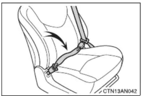
natural_image
Diagram of a car seatbelt buckle being lifted, showing rope routing and angle marking (no text or symbols)If your seat belts cannot be fastened securely because they are not long enough, a personalized seat belt extender is available from your Toyota dealer free of charge.

CAUTION
Observe the following precautions to reduce the risk of injury in the event of sudden braking, sudden swerving or an accident.
Failure to do so may cause death or serious injury.
■Wearing a seat belt
●Ensure that all passengers wear a seat belt.
●Always wear a seat belt properly.
● Each seat belt should be used by one person only. Do not use a seat belt for more than one person at once, including children.
●Toyota recommends that children be seated in the rear seat and always use a seat belt and/or an appropriate child restraint system.
●To achieve a proper seating position, do not recline the seat more than necessary. The seat belt is most effective when the occupants are sitting up straight and well back in the seats.
●Do not wear the shoulder belt under your arm.
●Always wear your seat belt low and snug across your hips.
■ Pregnant women
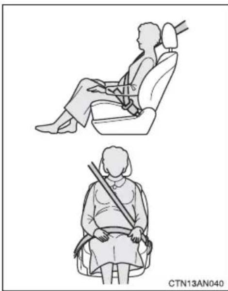
natural_image
Two illustrations of a person seated in car seats, one using a seatbelt and the other holding a long rod (no text or symbols)Obtain medical advice and wear the seat belt in the proper way. (→P. 131)
Women who are pregnant should position the lap belt as low as possible over the hips in the same manner as other occupants. Extend the shoulder belt completely over the shoulder and position the belt across the chest. Avoid belt contact over the rounding of the abdominal area.
If the seat belt is not worn properly, not only the pregnant woman, but also the fetus could suffer death or serious injury as a result of sudden braking or a collision.

CAUTION
■People suffering illness
Obtain medical advice and wear the seat belt in the proper way. ( P. 131)
■When children are in the vehicle
Do not allow children to play with the seat belt. If the seat belt becomes twisted around a child's neck, it may lead to choking or other serious injuries that could result in death.
If this occurs and the buckle cannot be unfastened, scissors should be used to cut the belt.
■Seat belt pretensioners
- Do not place anything, such as a cushion, on the front passenger's seat. Doing so will disperse the passenger's weight, which prevents the sensor from detecting the passenger's weight properly. As a result, the seat belt pretensioner for the front passenger's seat may not activate in the event of a collision.
- If the pretensioner has activated, the SRS warning light will come on. In that case, the seat belt cannot be used again and must be replaced at your Toyota dealer.
■Adjustable shoulder anchor
Always make sure the shoulder belt is positioned across the center of your shoulder. The belt should be kept away from your neck, but not falling off your shoulder. Failure to do so could reduce the amount of protection in an accident and cause death or serious injuries in the event of a sudden stop, sudden swerve or accident. ( P. 132)

CAUTION
■Seat belt damage and wear
- Do not damage the seat belts by allowing the belt, plate, or buckle to be jammed in the door.
- Inspect the seat belt system periodically. Check for cuts, fraying, and loose parts. Do not use a damaged seat belt until it is replaced. Damaged seat belts cannot protect an occupant from death or serious injury.
- Ensure that the belt and plate are locked and the belt is not twisted. If the seat belt does not function correctly, immediately contact your Toyota dealer.
- Replace the seat assembly, including the belts, if your vehicle has been involved in a serious accident, even if there is no obvious damage.
- Do not attempt to install, remove, modify, disassemble or dispose of the seat belts. Have any necessary repairs carried out by your Toyota dealer. Inappropriate handling of the pretensioner may prevent it from operating properly, resulting in death or serious injury.
■When using the rear center seat belt
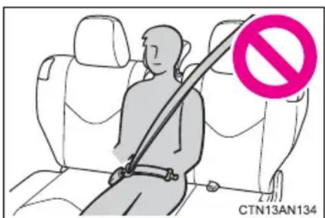
Do not use the rear center seat belt with either buckle released.
Fastening only one of the buckles may result in death or serious injury in case of sudden braking or a collision.
■ Using a seat belt extender
- Do not wear the seat belt extender if you can fasten the seat belt without the extender.
- Do not use the seat belt extender when installing a child restraint system because the belt will not securely hold the child restraint system, increasing the risk of death or serious injury in the event of an accident.
●The personalized extender may not be safe on another vehicle, when used by another person, or at a different seating position other than the one originally intended.

NOTICE
■When using a seat belt extender
When releasing the seat belt, press on the buckle release button on the extender, not on the seat belt.
This helps prevent damage to the vehicle interior and the extender itself.
1-6. Adjustable components (seats, mirrors, steering wheel) Steering wheel
The steering wheel can be adjusted to a comfortable position.
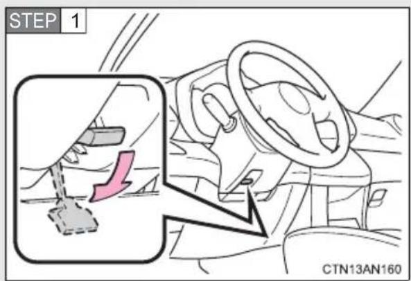
Hold the steering wheel and push the lever down.
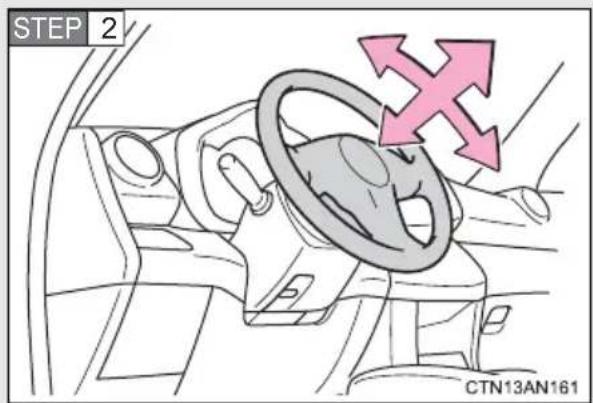
Adjust to the ideal position by moving the steering wheel horizontally and vertically.
After adjustment, pull the lever up to secure the steering wheel.

CAUTION
■Caution while driving
Do not adjust the steering wheel while driving.
Doing so may cause the driver to mishandle the vehicle and cause an accident, resulting in death or serious injury.
■After adjusting the steering wheel
Make sure that the steering wheel is securely locked.
Otherwise, the steering wheel may move suddenly, possibly causing an accident, and resulting in death or serious injury.
1-6. Adjustable components (seats, mirrors, steering wheel) Anti-glare inside rear view mirror
The rear view mirror's position can be adjusted to enable sufficient confirmation of the rear view in accordance with the driver's seating posture.
Adjusting the height of rear view mirror
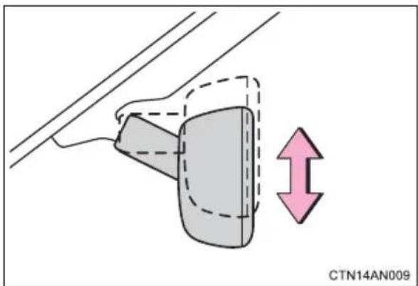
natural_image
Diagram of a mechanical component with a highlighted section and directional arrow, no readable text or symbols present.Adjust the height of the rear view mirror by moving it up and down.
Automatic anti-glare function
Responding to the level of brightness of the headlights of vehicles behind, the reflected light is automatically reduced.
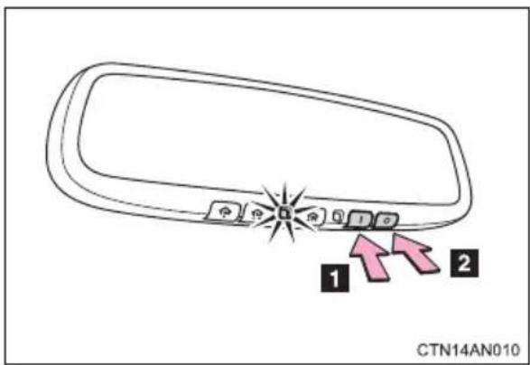
Changing automatic anti-glare function mode
1 ON
2 OFF
When the automatic anti-glare function is in ON mode, the indicator illuminates.
The function will set to ON mode each time the "POWER" switch is turned to ON mode.
■To prevent sensor error
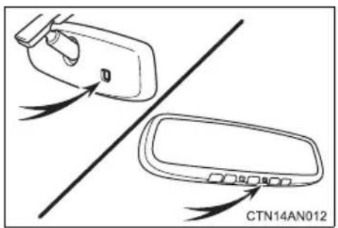
natural_image
Diagram showing two car door lockers with arrows indicating movement, no text or symbols presentTo ensure that the sensors operate properly, do not touch or cover them.

CAUTION
■Caution while driving
Do not adjust the position of the mirror while driving.
Doing so may lead to mishandling of the vehicle and an accident, resulting in death or serious injury.
1-6. Adjustable components (seats, mirrors, steering wheel) Outside rear view mirrors
Mirror angle can be adjusted using the switch.
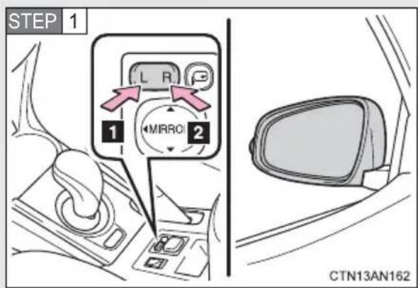
To select a mirror to adjust, press the switch.
1 Left
2 Right
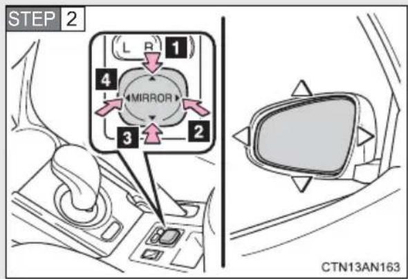
To adjust the mirror, press the switch.
1 Up
2 Right
3 Down
4 Left
Folding the mirrors
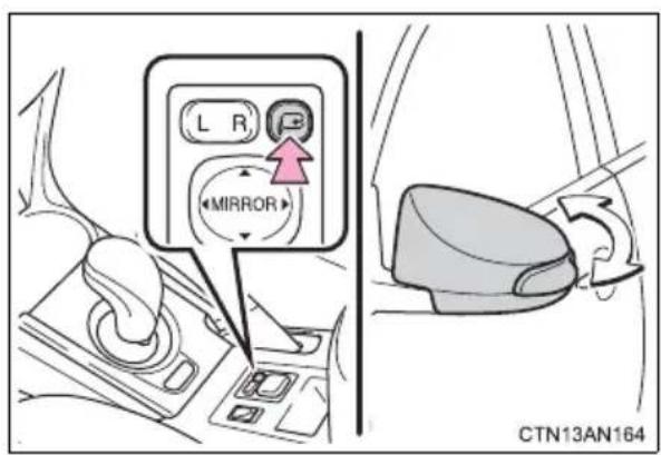
Press the switch to fold the mirrors.
Press it again to extend them to the original position.
■Mirror angle can be adjusted when
The "POWER" switch is in ACCESSORY or ON mode.
■When the mirrors are fogged up
The outside rear view mirrors can be cleared using the mirror defoggers. Turn on the rear window defogger to turn on the outside rear view mirror defoggers. ( P. 292)

CAUTION
■When driving the vehicle
Observe the following precautions while driving.
Failure to do so may result in loss of control of the vehicle and cause an accident, resulting in death or serious injury.
- Do not adjust the mirrors while driving.
- Do not drive with the mirrors folded.
● Both the driver and passenger side mirrors must be extended and properly adjusted before driving.
■When a mirror is moving
To avoid personal injury and mirror malfunction, be careful not to get your hand caught by the moving mirror.
■When the mirror defoggers are operating
Do not touch the rear view mirror surfaces, as they can become very hot and burn you.
The power windows can be opened and closed using the switches.
Operating the switch moves the windows as follows:
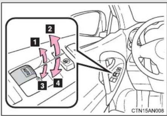
1 Closing
2 One-touch closing (driver's window only)*
3 Opening
4 One-touch opening (driver's window only)*
*: To stop the window partway, operate the switch in the opposite direction.
Window lock switch
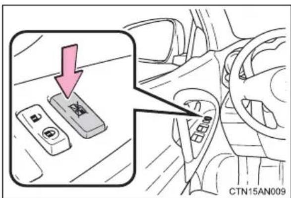
Press the switch down to lock the passenger window switches.
Use this switch to prevent children from accidentally opening or closing a passenger window.
■The power windows can be operated when
The "POWER" switch is in ON mode.
- Operating the power windows after turning the “POWER” switch off (front windows only)
The power windows can be operated for approximately 45 seconds after the "POWER" switch is turned to ACCESSORY mode or turned off. They cannot, however, be operated once either front door is opened.
Jam protection function (driver's window only)
If an object becomes caught between the window and the window frame, window travel is stopped and the window is opened slightly.
- When the power window does not close normally (driver's window only)
If the jam protection function is operating abnormally and a window cannot be closed, perform the following operations using the power window switch on the driver's door.
● After stopping the vehicle, the window can be closed by holding the power window switch in the one-touch closing position while the "POWER" switch is turned to ON mode.
- If the window still cannot be closed even by carrying out the operation explained above, initialize the function by performing the following procedure.
STEP 1
Hold the power window switch in the one-touch closing position. Continue holding the switch for a further 6 seconds after the window has closed.
STEP 2
Hold the power window switch in the one-touch opening position. Continue holding the switch for a further 2 seconds after the window has opened completely.
STEP 3
Hold the power window switch in the one-touch closing position once again. Continue holding the switch for a further 2 seconds after the window has closed.
If you release the switch while the window is moving, start again from the beginning.
If the window continues to close but then re-open slightly even after performing the above procedure correctly, have the vehicle inspected by your Toyota dealer.

CAUTION
■ Closing the windows
Observe the following precautions.
Failure to do so may result in death or serious injury.
- Check to make sure that all passengers do not have any part of their body in a position where it could be caught when a window is being operated.
- Do not allow children to operate the power windows.
Closing a power window on someone can cause serious injury, and in some instances, even death.
■Jam protection function (driver's window only)
● Never use any part of your body to intentionally activate the jam protection function.
●The jam protection function may not work if something gets caught just before the window fully closes.
The vehicle's keys have built-in transponder chips that prevent the EV system from starting if the key has not been previously registered in the vehicle's on-board computer.
Never leave the keys inside the vehicle when you leave the vehicle.
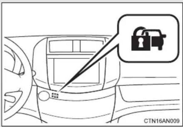
The indicator light flashes after the "POWER" switch has been turned off to indicate that the system is operating.
The indicator light stops flashing after the "POWER" switch has been turned to ACCESSORY or ON mode to indicate that the system has been canceled.
System maintenance
The vehicle has a maintenance-free type immobilizer system.
■Conditions affecting operation
Depending on the surrounding environment and conditions, the immobilizer system may not operate properly. This may prevent the EV system from starting. (→P. 104)
■Certifications for the immobilizer system
FCC ID: NI4TMIMB-1
This device complies with Part 15 of the FCC Rules. Operation is subject to the following two conditions: (1) this device may not cause harmful interference, and (2) this device must accept any interference received, including interference that may cause undesired operation.
FCC WARNING:
Changes or modifications not expressly approved by the party responsible for compliance could void the user's authority to operate the equipment.

NOTICE
■To ensure the system operates correctly
Do not modify or remove the system. If modified or removed, the proper operation of the system cannot be guaranteed.
1-8. Theft deterrent system
Theft prevention labels
These labels are attached to the vehicle to reduce vehicle theft by facilitating the tracing and recovery of parts from stolen vehicles. Do not remove under penalty of law.
Drive with a good posture as follows:
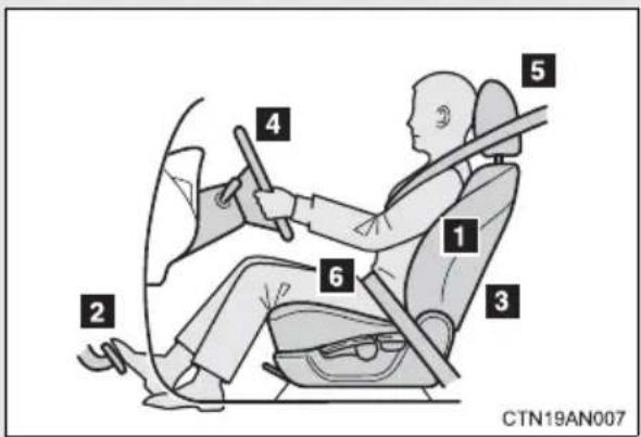
1 Sit upright and well back in the seat. (→P. 118)
2 Adjust the position of the seat forward or backward to ensure the pedals can be reached and easily depressed to the extent required. (→P. 118)
3 Adjust the seatback so that the controls are easily operable. (→P. 118)
4 Adjust the tilt and telescopic positions of the steering wheel downward so the air-bag is facing your chest. (→P. 140)
5 Lock the head restraint in place with the center of the head restraint closest to the top of your ears. (→P. 127)
6 Wear the seat belt correctly.
(→P. 131)

CAUTION
■While driving
- Do not adjust the position of the driver's seat.
Doing so could cause the driver to lose control of the vehicle. - Do not place a cushion between the driver or passenger and the seatback. A cushion may prevent correct posture from being achieved, and reduce the effectiveness of the seat belt and head restraint, increasing the risk of death or serious injury to the driver or passenger.
- Do not place anything under the front seats.
Objects placed under the front seats may become jammed in the seat tracks and stop the seat from locking in place. This may lead to an accident, resulting in death or serious injury. The adjustment mechanism may also be damaged.
■Adjusting the seat position
●Take care when adjusting the seat position to ensure that other passengers are not injured by the moving seat.
- Do not put your hands under the seat or near the moving parts to avoid injury.
Fingers or hands may become jammed in the seat mechanism.
The SRS airbags inflate when the vehicle is subjected to certain types of severe impacts that may cause significant injury to the occupants. They work together with the seat belts to help reduce the risk of death or serious injury.
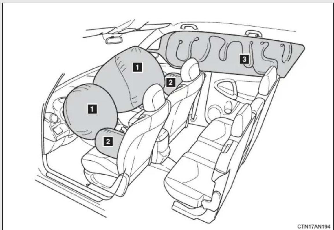
SRS front airbags
1 SRS driver airbag/front passenger airbag
Can help protect the head and chest of the driver and front passenger from impact with interior components
SRS side and curtain shield airbags
2 SRS side airbags
Can help protect the torso of the front seat occupants
3 SRS curtain shield airbags
Can help protect primarily the head of occupants in the outer seats
Airbag system components
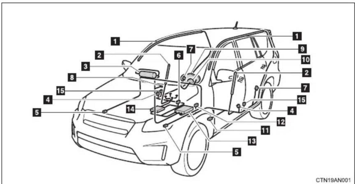
1 Curtain shield airbags
2 Side airbags
3 Front passenger airbag
4 Side impact sensors (front)
5 Front impact sensors
6 Front passenger's seat belt buckle switch
7 Side impact sensors (rear)
8 "AIR BAG ON" and "AIR BAG OFF" indicator lights
9 SRS warning light
10 Driver airbag
11 Driver's seat position sensor
12 Driver's seat belt buckle switch
13 Airbag sensor assembly
14 Front passenger occupant classification system (ECU and sensors)
15 Seat belt pretensioners and force limiters
Your vehicle is equipped with ADVANCED AIRBAGS designed based on the US motor vehicle safety standards (FMVSS208). The airbag sensor assembly (ECU) controls airbag deployment based on information obtained from the sensors etc. shown in the system components diagram above. This information includes crash severity and occupant information. As the airbags deploy, a chemical reaction in the inflators quickly fills the airbags with non-toxic gas to help restrain the motion of the occupants.
■If the SRS airbags deploy (inflate)
● Bruising and slight abrasions may result from contact with a deploying (inflating) SRS airbag.
●A loud noise and white powder will be emitted.
●Parts of the airbag module (steering wheel hub, airbag cover and inflator) as well as the front seats, parts of the front and rear pillars, and roof side rail, may be hot for several minutes. The airbag itself may also be hot.
●The windshield may crack.
For Safety Connect subscribers, if the SRS airbags deploy or in the event of a severe rear-end collision, the system is designed to send an emergency call to the response center, notifying them of the vehicle's location (without needing to push the "SOS" button) and an agent will attempt to speak with the occupants to ascertain the level of emergency and assistance required. If the occupants are unable to communicate, the agent automatically treats the call as an emergency and helps to dispatch the necessary emergency services. (→P. 326)
■ SRS airbag deployment conditions (SRS front airbags)
●The SRS front airbags will deploy in the event of an impact that exceeds the set threshold level (the level of force corresponding to an approximately 12-18 mph [20-30 km/h] frontal collision with a fixed wall that does not move or deform).
However, this threshold velocity will be considerably higher in the following situations:
- If the vehicle strikes an object, such as a parked vehicle or sign pole, which can move or deform on impact
- If the vehicle is involved in an underride collision, such as a collision in which the front of the vehicle “underrides”, or goes under, the bed of a truck
●Depending on the type of collision, it is possible that only the seat belt pretensioners will activate.
●The SRS front airbags for the front passenger will not activate if there is no passenger sitting in the front passenger seat. However, the SRS front airbags for the front passenger may deploy if luggage is put in the seat, even if the seat is unoccupied.
■ SRS airbag deployment conditions (SRS side and curtain shield airbags)
●The SRS side and curtain shield airbags will deploy in the event of an impact that exceeds the set threshold level (the level of force corresponding to the impact force produced by an approximately 3300 lb. [1500 kg] vehicle colliding with the vehicle cabin from a direction perpendicular to the vehicle orientation at an approximate speed of 12-18 mph [20-30 km/h]).
●The SRS curtain shield airbags will deploy in the event of vehicle rollover.
●The SRS side airbag on the passenger seat will not activate if there is no passenger sitting in the front passenger seat. However, the SRS side airbag on the passenger seat may deploy if luggage is put in the seat, even if the seat is unoccupied. (→P. 166)
■Conditions under which the SRS airbags may deploy (inflate), other than a collision
The SRS front airbags may also deploy if a serious impact occurs to the underside of your vehicle. Some examples are shown in the illustration.
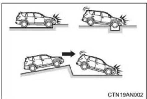
●Hitting a curb, edge of pavement or hard surface
●Falling into or jumping over a deep hole
●Landing hard or falling
The SRS curtain shield airbags may also deploy under the situations shown in the illustration.
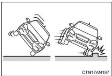
natural_image
Two cartoon-style car illustrations showing dynamic collision or damage on ground, with one falling and the other on a surface (no text or symbols)●The angle of vehicle tip-up is marginal.
●The vehicle skids and hits a curb stone.
■ Types of collisions that may not deploy the SRS airbags (SRS front airbags)
The SRS front airbags do not generally inflate if the vehicle is involved in a side or rear collision, if it rolls over, or if it is involved in a low-speed frontal collision. But, whenever a collision of any type causes sufficient forward deceleration of the vehicle, deployment of the SRS front airbags may occur.
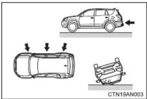
natural_image
Diagram showing three car under collision scenarios with arrows indicating motion (no text or symbols)- Collision from the side
- Collision from the rear
● Vehicle rollover
■Types of collisions that may not deploy the SRS airbags (SRS side and curtain shield airbags)
The SRS side and curtain shield airbags may not activate if the vehicle is subjected to a collision from the side at certain angles, or a collision to the side of the vehicle body other than the passenger compartment.
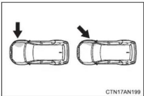
natural_image
Top-down diagram of two cars with arrows indicating motion direction (no text or symbols)- Collision from the side to the vehicle body other than the passenger compartment
●Collision from the side at an angle
The SRS side airbags do not generally inflate if the vehicle is involved in a frontal or rear collision, if it rolls over, or if it is involved in a low-speed side collision.
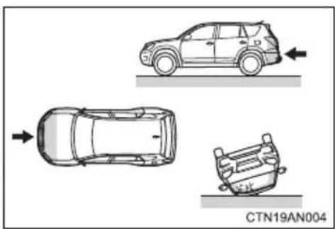
natural_image
Top-down diagram of three cars with directional arrows indicating movement or collision (no text or symbols on the car bodies)- Collision from the front
- Collision from the rear
● Vehicle rollover
The SRS curtain shield airbags do not generally inflate if the vehicle is involved in a frontal or rear collision, if it pitches end over end, or if it is involved in a low-speed side collision.
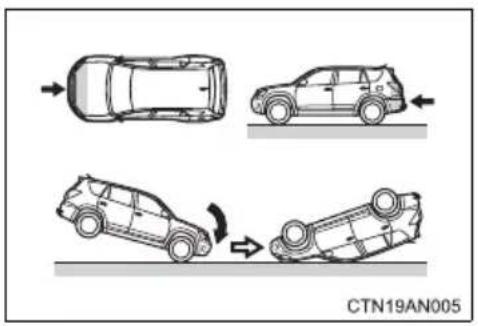
- Collision from the front
- Collision from the rear
- Pitching end over end
■When to contact your Toyota dealer
In the following cases, the vehicle will require inspection and/or repair. Contact your Toyota dealer as soon as possible.
●Any of the SRS airbags have been inflated.
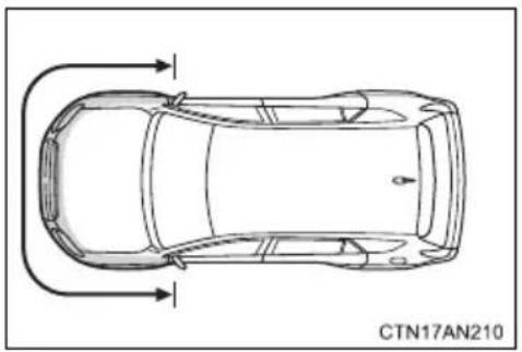
natural_image
Top-down line drawing of a car with directional arrows indicating flow or movement (no text or symbols)●The front of the vehicle is damaged or deformed, or was involved in an accident that was not severe enough to cause the SRS front airbags to inflate.
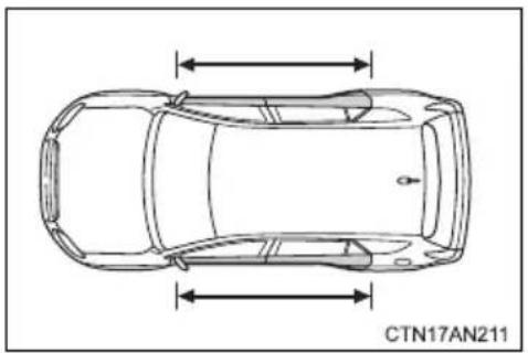
natural_image
Top-down line drawing of a car with horizontal double-headed arrows indicating vertical motion (no text or symbols on the diagram itself)●A portion of a door is damaged or deformed, or the vehicle was involved in an accident that was not severe enough to cause the SRS side and curtain shield airbags to inflate.
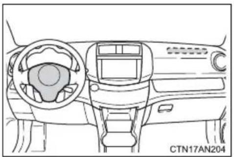
natural_image
Front view of a car dashboard and steering wheel (no text or symbols visible)●The pad section of the steering wheel or dashboard near the front passenger airbag is scratched, cracked, or otherwise damaged.
1-9. Safety information
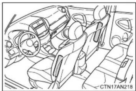
natural_image
Line drawing of a car interior showing steering wheel, dashboard, and seats (no text or symbols)●The surface of the seats with the side airbag is scratched, cracked or otherwise damaged.
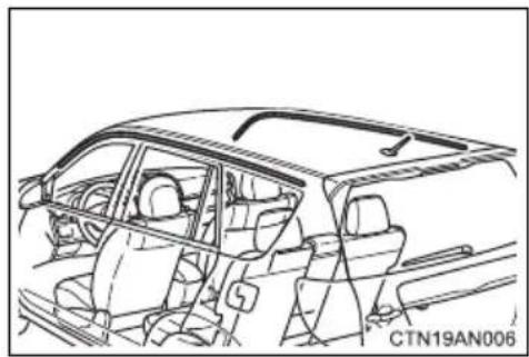
natural_image
Line drawing of a car interior showing dashboard, seats, and steering wheel (no text or symbols)●The portion of the front pillars, rear pillars or roof side rail garnishes (padding) containing the curtain shield airbags inside is scratched, cracked or otherwise damaged.

CAUTION
■ SRS airbag precautions
Observe the following precautions regarding the SRS airbags.
Failure to do so may cause death or serious injury.
●The driver and all passengers in the vehicle must wear their seat belts properly.
The SRS airbags are supplemental devices to be used with the seat belts.
●The SRS driver airbag deploys with considerable force, and can cause death or serious injury especially if the driver is very close to the airbag. The National Highway Traffic Safety Administration (NHTSA) advises:
Since the risk zone for the driver's airbag is the first 2 - 3 in. (50 - 75 mm) of inflation, placing yourself 10 in. (250 mm) from your driver airbag provides you with a clear margin of safety. This distance is measured from the center of the steering wheel to your breastbone. If you sit less than 10 in. (250 mm) away now, you can change your driving position in several ways:
- Move your seat to the rear as far as you can while still reaching the pedals comfortably.
- Slightly recline the back of the seat.
Although vehicle designs vary, many drivers can achieve the 10 in. (250 mm) distance, even with the driver seat all the way forward, simply by reclining the back of the seat somewhat. If reclining the back of your seat makes it hard to see the road, raise yourself by using a firm, non-slippery cushion, or raise the seat if your vehicle has that feature. - If your steering wheel is adjustable, tilt it downward. This points the airbag toward your chest instead of your head and neck.
The seat should be adjusted as recommended by NHTSA above, while still maintaining control of the foot pedals, steering wheel, and your view of the instrument panel controls.

CAUTION
■SRS airbag precautions

- If the seat belt extender has been connected to the front seat belt buckles but the seat belt extender has not also been fastened to the latch plate of the seat belt, the SRS front airbags will judge that the driver and front passenger are wearing the seat belt even though the seat belt has not been connected. In this case, the SRS front airbags may not activate correctly in a collision, resulting in death or serious injury in the event of a collision. Be sure to wear the seat belt with the seat belt extender.
●The SRS front passenger airbag also deploys with considerable force, and can cause death or serious injury especially if the front passenger is very close to the airbag. The front passenger seat should be as far from the airbag as possible with the seatback adjusted, so the front passenger sits upright.
- Improperly seated and/or restrained infants and children can be killed or seriously injured by a deploying airbag. An infant or child who is too small to use a seat belt should be properly secured using a child restraint system. Toyota strongly recommends that all infants and children be placed in the rear seats of the vehicle and properly restrained. The rear seats are safer for infants and children than the front passenger seat. (→P. 172)

CAUTION
■ SRS airbag precautions
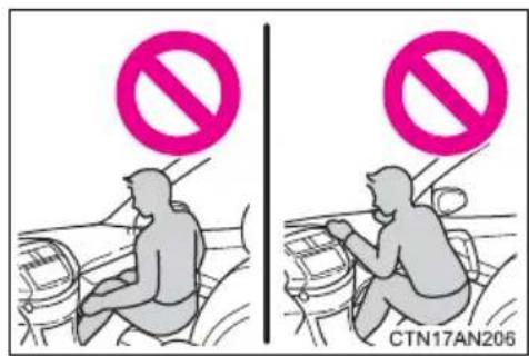
- Do not sit on the edge of the seat or lean against the dashboard.
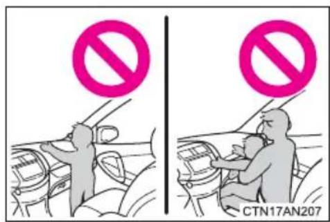
- Do not allow a child to stand in front of the SRS front passenger airbag unit or sit on the knees of a front passenger.
- Do not allow the front seat occupants to hold items on their knees.
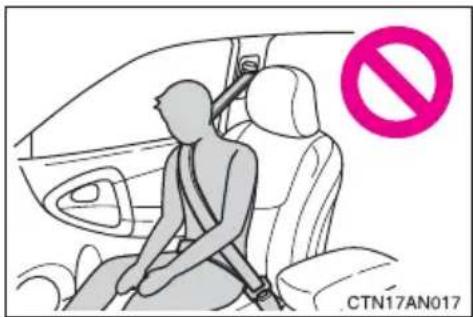
- Do not lean against the door, the roof side rail or the front, side and rear pillars.
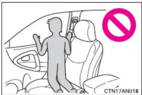
- Do not allow anyone to kneel on the passenger seat toward the door or put their head or hands outside the vehicle.
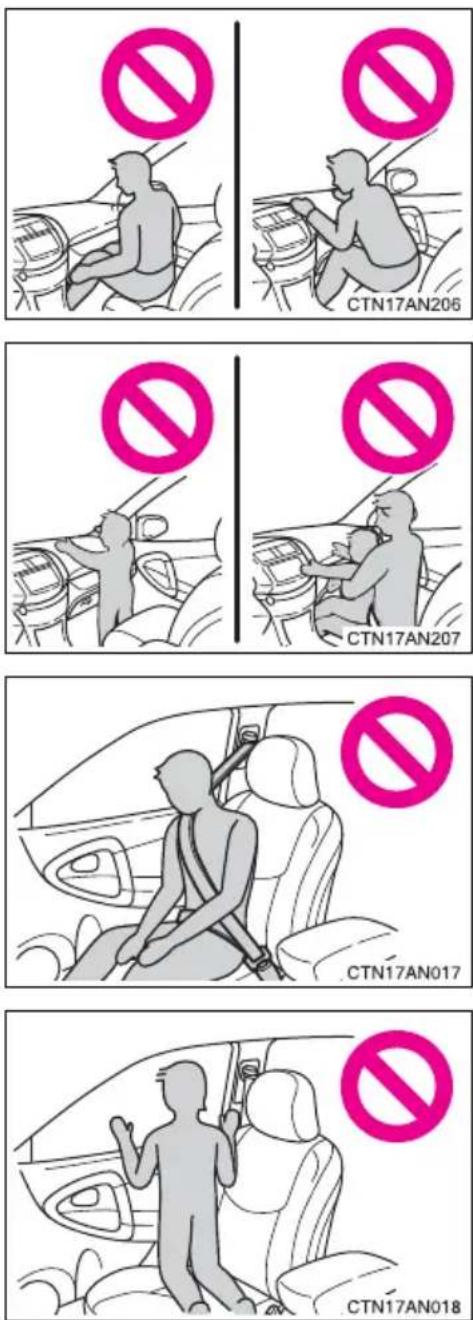

CAUTION
■SRS airbag precautions
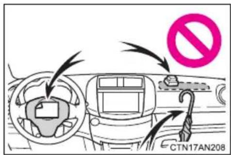
- Do not attach anything to or lean anything against areas such as the dashboard or steering wheel pad. These items can become projectiles when the SRS driver and front passenger airbags deploy.
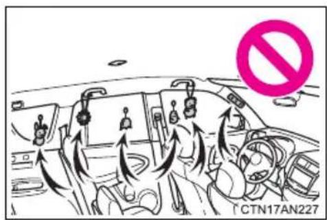
- Do not attach anything to areas such as a door, windshield glass, side door glass, front or rear pillar, roof side rail and assist grip. (Except for the speed limit label →P. 452)
- Do not hang coat hangers or other hard objects on the coat hooks. All of these items could become projectiles and may cause death or serious injury, should the SRS curtain shield airbags deploy.
- Do not use seat accessories which cover the parts where the SRS side airbags inflate as they may interfere with inflation of the airbags. Such accessories may prevent the side airbags from activating correctly, disable the system or cause the side airbags to inflate accidentally, resulting in death or serious injury.
- Do not strike or apply significant levels of force to the area of the SRS air-bag components.
Doing so can cause the SRS airbags to malfunction.

CAUTION
■SRS airbag precautions
- Do not touch any of the component parts immediately after the SRS airbags have deployed (inflated) as they may be hot.
- If breathing becomes difficult after the SRS airbags has deployed, open a door or window to allow fresh air in, or leave the vehicle if it is safe to do so. Wash off any residue as soon as possible to prevent skin irritation.
- If the areas where the SRS airbags are stored, such as the steering wheel pad and front and rear pillar garnishes, are damaged or cracked, have them replaced by your Toyota dealer.
- Do not place anything, such as a cushion, on the front passenger's seat. Doing so will disperse the passenger's weight, which prevents the sensor from detecting the passenger's weight properly. As a result, the SRS front passenger airbag may not deploy in the event of a collision.
■ Modification and disposal of SRS airbag system components
Do not dispose of your vehicle or perform any of the following modifications without consulting your Toyota dealer.
The SRS airbags may malfunction or deploy (inflate) accidentally, causing death or serious injury.
●Installation, removal, disassembly and repair of the SRS airbags
● Repairs, modifications, removal or replacement of the steering wheel, instrument panel, dashboard, seats or seat upholstery, front, side and rear pillars or roof side rails
● Repairs or modifications of the front fender, front bumper, or side of the occupant compartment
● Installation of snow plows, winches, etc. to the front grille (bull bars or kangaroo bar etc.) or roof luggage carrier
●Modifications to the vehicle's suspension system
● Installation of electronic devices such as mobile two-way radios or CD players
● Modifications to your vehicle for a person with a physical disability
1-9. Safety information
Front passenger occupant classification system
Your vehicle is equipped with a front passenger occupant classification system. This system detects the conditions of the front passenger seat and activates or deactivates the devices for the front passenger.
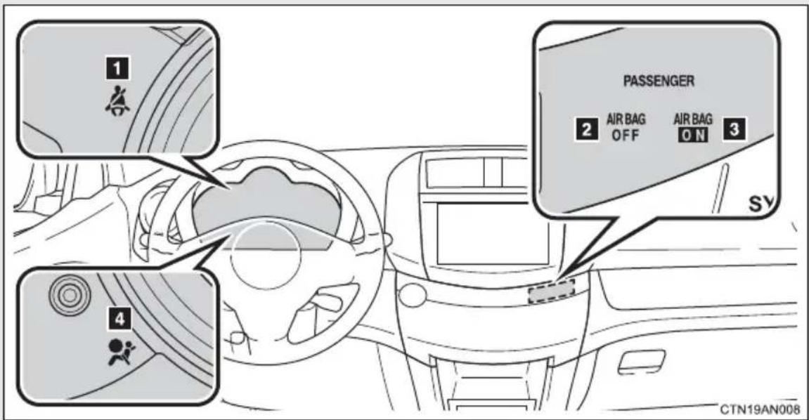
1 Seat belt reminder light
2 "AIR BAG OFF" indicator light
3 "AIR BAG ON" indicator light
4 SRS warning light
Conditions and operation of the front passenger occupant classification system
Adult\* 1
| Indicator/warning light | “AIR BAG ON” and “AIR BAG OFF” indicator lights | “AIR BAG ON” |
| SRS warning light Off | ||
| Seat belt reminder light | Flashing^*2 | |
| Devices | Front passenger airbag | Activated |
| Side airbag on the front passenger seat | ||
| Curtain shield airbag in the front passenger side | ||
| Front passenger's seat belt pretensioner |
■Child\* ^3 or child restraint system\* ^4
| Indicator/warning light | “AIR BAG ON” and “AIR BAG OFF” indicator lights | “AIR BAG OFF”*5 |
| SRS warning light Off | ||
| Seat belt reminder light Flashing* | 2 | |
| Devices | Front passenger airbag | Deactivated |
| Side airbag on the front passenger seat | ||
| Curtain shield airbag in the front passenger side | Activated | |
| Front passenger's seat belt pretensioner |
Unoccupied
| Indicator/warning light | “AIR BAG ON” and “AIR BAG OFF” indicator lights | Not illuminated |
| SRS warning light | Off | |
| Seat belt reminder light | ||
| Devices | Front passenger airbag | Deactivated |
| Side airbag on the front passenger seat | ||
| Curtain shield airbag in the front passenger side | Activated | |
| Front passenger's seat belt pretensioner | Deactivated |
■There is a malfunction in the system
| Indicator/warning light | “AIR BAG ON” and “AIR BAG OFF” indicator lights | “AIR BAG OFF” |
| SRS warning light On | ||
| Seat belt reminder light On | ||
| Devices | Front passenger airbag | Deactivated |
| Side airbag on the front passenger seat | ||
| Curtain shield airbag in the front passenger side | Activated | |
| Front passenger's seat belt pretensioner |
*1: The system judges a person of adult size as an adult. When a smaller adult sits in the front passenger seat, the system may recognize him/her as a child depending on his/her physique and posture.
*2: In the event the front passenger does not wear a seat belt.
*3: When a larger child who has outgrown a child restraint system sits in the front passenger seat, the system may recognize him/her as an adult depending on his/her physique or posture.
*4: Never install a rear-facing child restraint system on the front passenger seat. A forward-facing child restraint system should only be installed on the front passenger seat when it is unavoidable. (→P. 172)
*5: In case the indicator light is not illuminated, consult this manual on how to install the child restraint system properly. (→P. 176)

CAUTION
■ Front passenger occupant classification system precautions
Observe the following precautions regarding the front passenger occupant classification system.
Failure to do so may cause death or serious injury.
●Wear the seat belt properly.
● Make sure the front passenger's seat belt plate has not been left inserted into the buckle before someone sits in the front passenger seat.
Make sure the “AIR BAG OFF” indicator light is not illuminated when using the seat belt extender for the front passenger seat. If the “AIR BAG OFF” indicator light is illuminated, disconnect the extender tongue from the seat belt buckle, and reconnect the seat belt. Reconnect the seat belt extender after making sure the “AIR BAG ON” indicator light is illuminated. If you use the seat belt extender while the “AIR BAG OFF” indicator light is illuminated, the front passenger airbag and side airbag on the front passenger side may not activate correctly, which could cause death or serious injury in the event of a collision.
- Do not apply a heavy load to the front passenger seat or equipment (e.g. seatback pocket).
- Do not put weight on the front passenger seat by putting your hands or feet on the front passenger seat seatback from the rear seat.
- Do not let a rear passenger lift the front passenger seat with their feet or press on the seatback with their legs.
- Do not put objects under the front passenger seat.
- Do not recline the front passenger seatback so far that it touches a rear seat. This may cause the “AIR BAG OFF” indicator light to be illuminated, which indicates that the passenger's airbags will not deploy in the event of a severe accident. If the seatback touches the rear seat, return the seatback to a position where it does not touch the rear seat. Keep the front passenger seatback as upright as possible when the vehicle is moving. Reclining the seatback excessively may lessen the effectiveness of the seat belt system.

CAUTION
■ Front passenger occupant classification system precautions
- If an adult sits in the front passenger seat, the “AIR BAG ON” indicator light is illuminated. If the “AIR BAG OFF” indicator is illuminated, ask the passenger to sit up straight, well back in the seat, feet on the floor, and with the seat belt worn correctly. If the “AIR BAG OFF” indicator still remains illuminated, either ask the passenger to move to the rear seat, or if that is not possible, move the front passenger seat fully rearward.
- When it is unavoidable to install a forward-facing child restraint system on the front passenger seat, install the child restraint system on the front passenger seat in the proper order. (→P. 176)
- Do not modify or remove the front seats.
- Do not kick the front passenger seat or subject it to severe impact. Otherwise, the SRS warning light may come on to indicate a malfunction of the detection system. In this case, contact your Toyota dealer immediately.
● Child restraint systems installed on the rear seat should not contact the front seatbacks. - Do not use a seat accessory, such as a cushion and seat cover, that covers the seat cushion surface.
●Do not modify or replace the upholstery of the front seat.
A child restraint system for a small child or baby must itself be properly restrained on the seat with the lap portion of the lap/shoulder belt.
The laws of all 50 states of the U.S.A. now require the use of child restraint systems.
Points to remember
Studies have shown that installing a child restraint on a rear seat is much safer than installing one on the front passenger seat.
- Choose a child restraint system that suits your vehicle and is appropriate to the age and size of the child.
●For installation details, follow the instructions provided with the child restraint system.
General installation instructions are provided in this manual. (→P. 176)
Types of child restraints
Child restraint systems are classified into the following 3 types according to the age and size of the child:
Rear facing — Infant seat/convertible seat
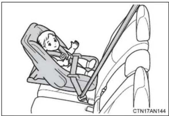
natural_image
Illustration of a child wearing a car seatbelt inside a vehicle, no text or symbols presentForward facing — Convertible seat
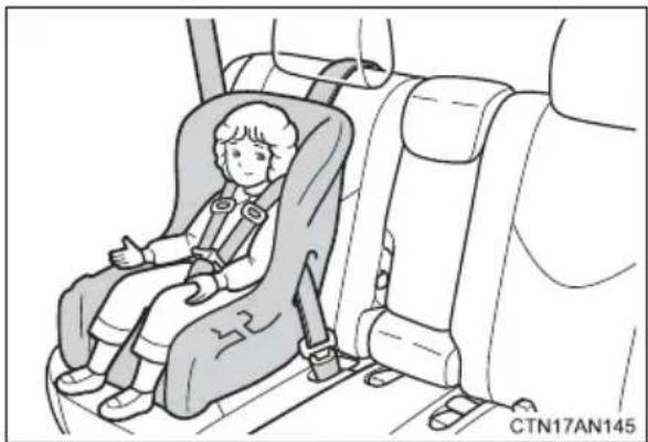
natural_image
Illustration of a child seated in a car seat inside a vehicle, no text or symbols presentBooster seat
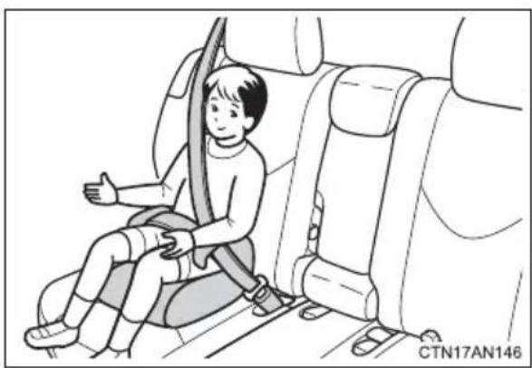
natural_image
Illustration of a child sitting in a car seatbelt, giving a thumbs-up (no text or symbols)■Selecting an appropriate child restraint system
- Use a child restraint system appropriate for the child until the child becomes large enough to properly wear the vehicle's seat belt.
- If the child is too large for a child restraint system, sit the child on a rear seat and use the vehicle's seat belt. (→P. 131)

CAUTION
■Child restraint precautions
- For effective protection in automobile accidents and sudden stops, a child must be properly restrained, using a seat belt or child restraint system depending on the age and size of the child. Holding a child in your arms is not a substitute for a child restraint system. In an accident, the child can be crushed against the windshield, or between you and the vehicle's interior.
Toyota strongly urges the use of a proper child restraint system that conforms to the size of the child, installed on the rear seat. According to accident statistics, the child is safer when properly restrained in the rear seat than in the front seat. - Never install a rear-facing child restraint system on the front passenger seat even if the “AIR BAG OFF” indicator light is illuminated.
In the event of an accident, the force of the rapid inflation of the front passenger airbag can cause death or serious injury to the child if the rear-facing child restraint system is installed on the front passenger seat.
A forward-facing child restraint system may be installed on the front passenger seat only when it is unavoidable. A child restraint system that requires a top tether strap should not be used in the front passenger seat since there is no top tether strap anchor for the front passenger seat. Adjust the seatback as upright as possible and always move the seat as far back as possible even if the “AIR BAG OFF” indicator light is illuminated, because the front passenger airbag could inflate with considerable speed and force. Otherwise, the child may be killed or seriously injured.

CAUTION
■Child restraint precautions
- Do not use the seat belt extender when installing a child restraint system on the front or rear passenger seat. If installing a child restraint system with the seat belt extender connected to the seat belt, the seat belt will not securely hold the child restraint system, which could cause death or serious injury to the child or other passengers in the event of a sudden stop, sudden swerve or accident.
- Do not allow the child to lean his/her head or any part of his/her body against the door or the area of the seat, front and rear pillars or roof side rails from which the SRS side airbags or SRS curtain shield airbags deploy even if the child is seated in the child restraint system. It is dangerous if the SRS side airbags and curtain shield airbags inflate, and the impact could cause death or serious injury to the child.
● Make sure you have complied with all installation instructions provided by the child restraint manufacturer and that the system is properly secured. If it is not secured properly, it may cause death or serious injury to the child in the event of a sudden stop, sudden swerve or an accident.
■When children are in the vehicle
Do not allow children to play with the seat belt. If the seat belt becomes twisted around a child's neck, it may lead to choking or other serious injuries that could result in death.
If this occurs and the buckle cannot be unfastened, scissors should be used to cut the belt.
■When the child restraint system is not in use
- Keep the child restraint system properly secured on the seat even if it is not in use.
Do not store the child restraint system unsecured in the passenger compartment. - If it is necessary to detach the child restraint system, remove it from the vehicle or store it securely in the luggage compartment. This will prevent it from injuring passengers in the event of a sudden stop, sudden swerve or accident.
Follow the child restraint system manufacturer's instructions. Firmly secure child restraints to the seats using the LATCH anchors or a seat belt. Attach the top tether strap when installing a child restraint.
The lap/shoulder belt can be used if your child restraint system is not compatible with the LATCH (Lower Anchors and Tethers for Children) system.
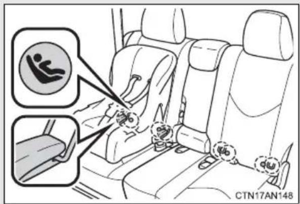
Rear outside seats: Child restraint LATCH anchors
LATCH anchors are provided for the rear outside seats. (Buttons displaying the location of the anchors are attached to the seats.)
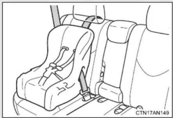
natural_image
Line drawing of a car seatbelt assembly with no text or symbolsSeat belts equipped with a child restraint locking mechanism (ALR/ELR belts except driver's seat belt) (→P. 134)
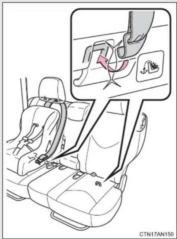
Rear outside seats: Anchor brackets (for top tether strap)
An anchor bracket is provided for each outer rear seat.
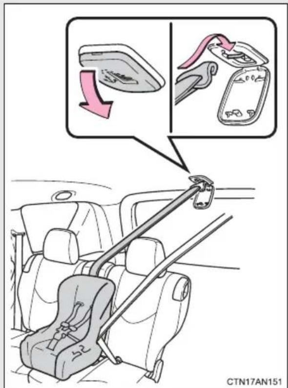
Rear center seat: Anchor bracket (for top tether strap)
An anchor bracket is provided for the rear center seat.
Installation with LATCH system (rear outside seats only)
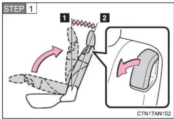
Fold the seatback while pulling the lever. Return the seatback and secure it at the 1st lock position (most upright position). Adjust the seatback to the 7th lock position. (→P. 121)
1 1st lock position
2 7th lock position
Type A
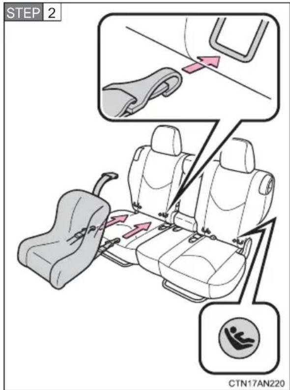
Latch the hooks of the lower straps onto the LATCH anchors.
The bars are installed in the clearance between the seat cushion and seatback.
If the child restraint has a top tether strap, the top tether strap should be latched onto the top tether strap anchor.
The symbol on a child restraint system indicates the presence of a lower connector system.
Type B
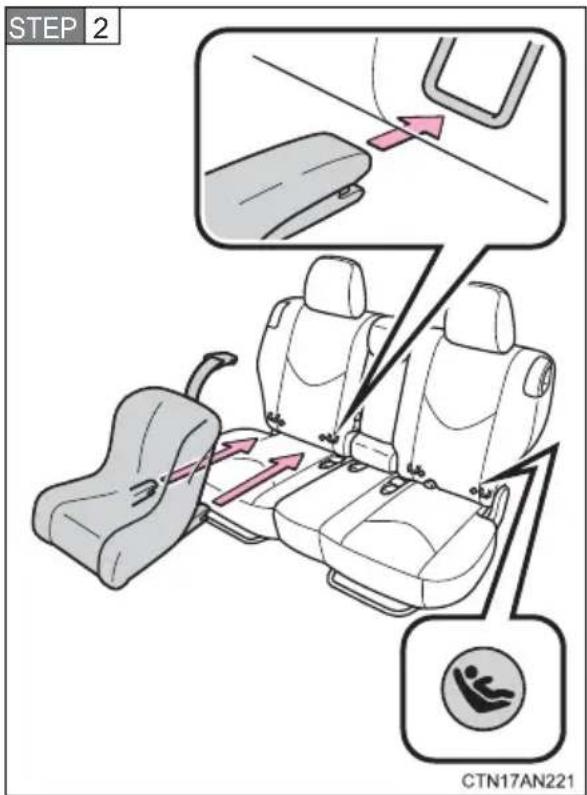
Latch the buckles onto the LATCH anchors.
The bars are installed in the clearance between the seat cushion and seatback.
If the child restraint has a top tether strap, the top tether strap should be latched onto the top tether strap anchor.
The symbol on a child restraint system indicates the presence of a lower connector system.
Installing child restraints using a seat belt (child restraint lock function belt)
■ Rear facing — Infant seat/convertible seat
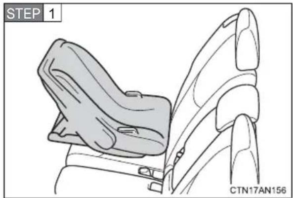
natural_image
Line drawing of a car seat assembly with no text or symbolsPlace the child restraint system on the rear seat facing the rear of the vehicle.
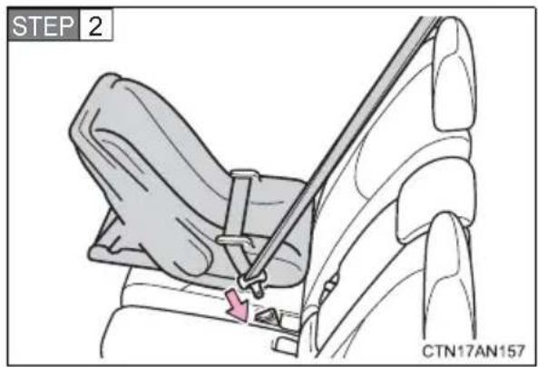
Run the seat belt through the child restraint system and insert the plate into the buckle. Make sure that the belt is not twisted.
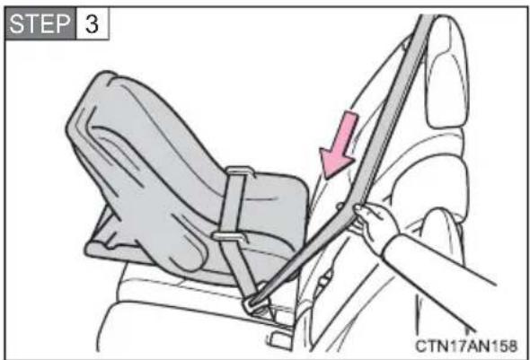
Fully extend the shoulder belt and then allow it to retract slightly in order to activate the ALR lock mode.
Lock mode allows the seat belt to retract only.
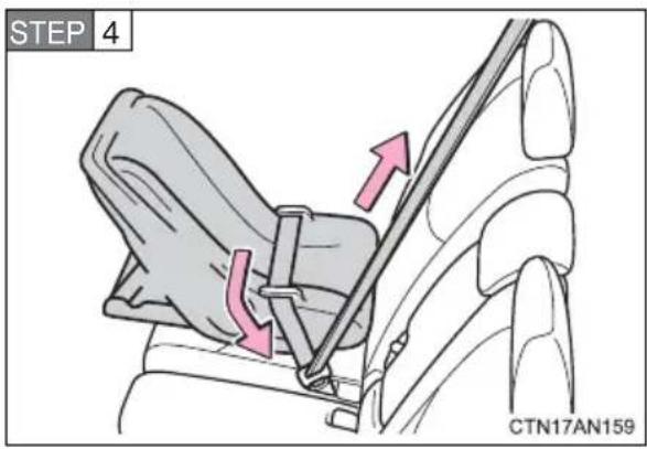
While pushing the child restraint system down into the rear seat, allow the shoulder belt to retract until the child restraint system is securely in place.
After the shoulder belt has retracted to a point where there is no slack in the belt, pull the belt to check that it cannot be extended.
■ Forward facing — Convertible seat
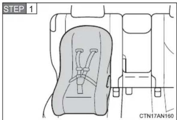
Place the child restraint system on the seat facing the front of the vehicle.
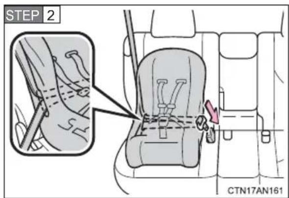
Run the seat belt through the child restraint system and insert the plate into the buckle. Make sure that the belt is not twisted.
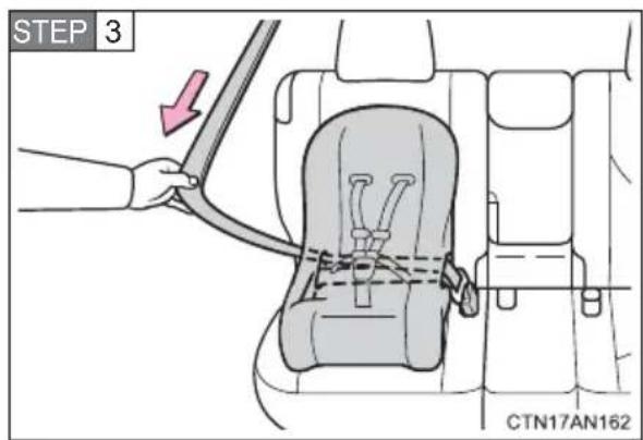
Fully extend the shoulder strap and then allow it to retract slightly into the ALR lock mode.
Lock mode allows the seat belt to retract only.
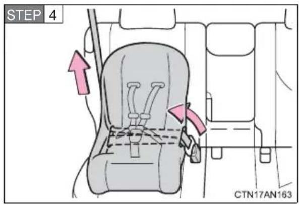
While pushing the child restraint system into the rear seat, allow the shoulder belt to retract until the child restraint system is securely in place.
After the shoulder belt has retracted to a point where there is no slack in the belt, pull the belt to check that it cannot be extended.
STEP 5 If the child restraint has a top tether strap, the top tether strap should be latched onto the top tether strap anchor. (→P. 183)
■ Booster seat
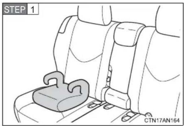
natural_image
Interior view of a car seatbelt with a highlighted seatbelt (no text or symbols)Place the child restraint system on the seat facing the front of the vehicle.
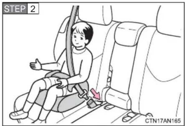
Sit the child in the child restraint system. Fit the seat belt to the child restraint system according to the manufacturer's instructions and insert the plate into the buckle. Make sure that the belt is not twisted.
Check that the shoulder belt is correctly positioned over the child's shoulder and that the lap belt is as low as possible.
$$ (\rightarrow \mathrm{P}. 1 3 1) $$
Removing a child restraint installed with a seat belt
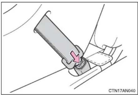
natural_image
Diagram showing a hand using a belt switch to adjust a seatbelt, with no text or symbols present.Push the buckle release button and fully retract the seat belt.
Child restraint systems with a top tether strap (rear seats only)
■Outside seats
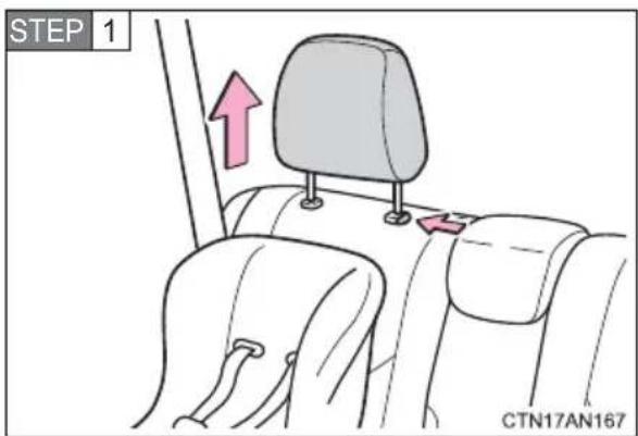
Remove the head restraint.
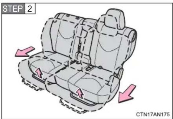
Slide the seats forward slightly if it is in the rear-most position.
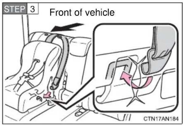
Secure the child restraint using the seat belt. Latch the hook onto the anchor bracket and tighten the top tether strap.
Make sure the top tether strap is securely latched.
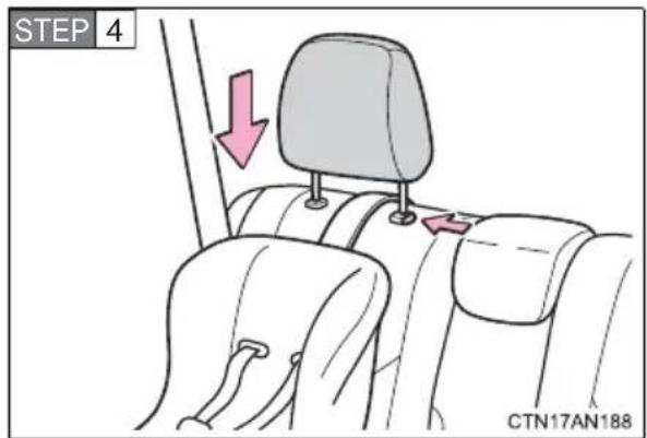
Replace the head restraint.
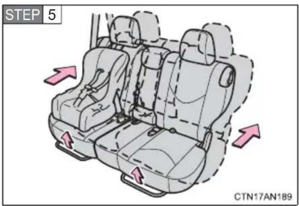
Move the seats to the rear-most lock position.
Center seat
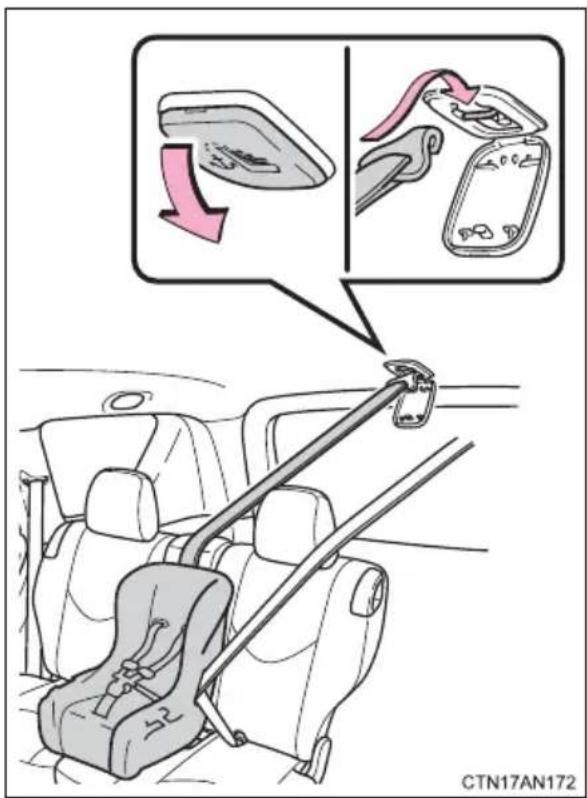
Open the anchor bracket cover. Secure the child restraint using the seat belt. Latch the hook onto the anchor bracket and tighten the top tether strap.
Make sure the top tether strap is securely latched.
■Laws and regulations pertaining to anchorages
The LATCH system conforms to FMVSS225 or CMVSS210.2.
Child restraint systems conforming to FMVSS213 or CMVSS213 specifications can be used.
This vehicle is designed to conform to SAE J1819.

CAUTION
■When installing a booster seat
Do not fully extend the shoulder belt to prevent the belt from going to ALR lock mode. (→P. 134)
ALR mode causes the belt to tighten only which could cause injury or discomfort to the child.
■When installing a child restraint system
Follow the directions given in the child restraint system installation manual and fix the child restraint system securely in place.
If the child restraint system is not correctly fixed in place, the child or other passengers may be seriously injured or even killed in the event of sudden braking, sudden swerving or an accident.
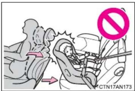
- If the driver's seat interferes with the child restraint system and prevents it from being attached correctly, attach the child restraint system to the right-hand rear seat.
- Adjust the front passenger seat or rear seats so that it does not interfere with the child restraint system.
- Only put a forward-facing or booster child seat on the front seat when unavoidable. When installing a forward-facing or booster child seat on the front passenger seat, move the seat as far back as possible even if “AIR BAG OFF” indicator light is illuminated. Failing to do so may result in death or serious injury if the airbags deploy (inflate).
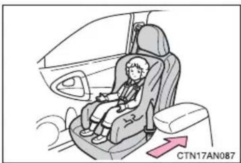
natural_image
Illustration of a child seated in a car seat inside a vehicle, with a pink arrow pointing to the right side (no text or symbols on the diagram itself)
CAUTION
■When installing a child restraint system
- When installing a child restraint system in the rear center seat, adjust both seat cushions to the same position and align seatbacks at the same angle. Otherwise, the child restraint system cannot be securely restrained and this may cause death or serious injuries in the event of sudden braking, sudden swerving or an accident.
- When using the LATCH anchors for a child restraint system, move the seat as far back as possible (rear seat only), with the seatback close to the child restraint system.
- When a booster seat is installed, always ensure that the shoulder belt is positioned across the center of the child's shoulder. The belt should be kept away from the child's neck, but not so that it could fall off the child's shoulder. Failing to do so may result in death or serious injury in the event of sudden braking, sudden swerving or an accident.
- Ensure that the belt and tab are securely locked and the seat belt is not twisted.
● Shake the child restraint system left and right, and forward and backward to ensure that it has been securely installed.
●After securing a child restraint system, never adjust the seat.
●Follow all installation instructions provided by the child restraint system manufacturer.
■Do not use a seat belt extender
If a seat belt extender is used when installing a child restraint system, the seat belt will not securely hold the child restraint system, which could cause death or serious injury to the child or other passengers in the event of sudden braking, sudden swerving or an accident.
■ To correctly attach a child restraint system to the anchors
When using the LATCH anchors, be sure that there are no foreign objects around the anchors and that the seat belt is not caught behind the child restraint. Make sure the child restraint system is securely attached, or it may cause death or serious injury to the child or other passengers in the event of a sudden stop, sudden swerve or accident.
1-9. Safety information
When driving
2
2-1. Driving procedures
Driving the vehicle...... 190
Power switch...... 200
Transmission...... 206
Turn signal lever 215
Parking brake.... 216
Horn 217
2-2. Instrument cluster
Gauges and meters ..... 218
Indicators and warning lights 223
Multi-information display.... 227
2-3. Operating the lights and wipers
Headlight switch...... 234
Windshield wipers and washer 238
Rear window wiper and washer 241
2-4. Using other driving systems
Cruise control.... 243
Rear view monitor system 247
Driving assist systems ..... 251
Hill-start assist control..... 256
2-5. Driving information
Utility vehicle precautions 258
Cargo and luggage 263
Vehicle load limits ...... 267
Winter driving tips ...... 268
Trailer towing 273
Dinghy towing 274
The following procedures should be observed to ensure safe driving.
■Starting the EV system
→P. 200
Driving
STEP 1 With the brake pedal depressed, select the D position.
(→P. 206)
Check that the shift position indicator shows D.
STEP 2 Release the parking brake. ( P. 216)
STEP 3 Gradually release the brake pedal and gently depress the
accelerator pedal to accelerate the vehicle.
Stopping
STEP 1 Depress the brake pedal.
STEP 2 If necessary, set the parking brake.
When the vehicle is stopped for an extended period of time, push the P position switch. ( P. 209)
Parking the vehicle
STEP 1 Depress the brake pedal until the vehicle comes to a complete stop.
STEP 2 Set the parking brake. ( P. 216)
STEP 3 Push the P position switch. (→P. 209)
Check that the shift position indicator shows P.
STEP 4 Press the "POWER" switch to stop the EV system.
STEP 5 Lock the door, making sure that you have the electronic key on your person.
Starting on a steep uphill
STEP 1 Firmly set the parking brake with the brake pedal depressed, and then shift the shift position to D.
STEP 2 Slowly release the brake pedal and gently depress the accelerator pedal.
STEP 3 Release the parking brake.
- Driving in the rain
●Drive carefully when it is raining, because visibility will be reduced, the windows may become fogged-up, and the road will be slippery.
- Drive carefully when it starts to rain, because the road surface will be especially slippery.
●Refrain from high speeds when driving on an expressway in the rain, because there may be a layer of water between the tires and the road surface, preventing the steering and brakes from operating properly.
■Breaking in your new Toyota
To extend the life of the vehicle, observing the following precautions is recommended:
●For the first 200 miles (300 km):
Avoid sudden stops.
●For the first 1000 miles (1600 km):
- Do not drive at extremely high speeds.
- Avoid sudden acceleration.
- Do not drive at a constant speed for extended periods.
■Drum-in-disc type parking brake system
Your vehicle has a drum-in-disc type parking brake system.
This type of brake system needs bedding-down of the brake shoes periodically or whenever the parking brake shoes and/or drum are replaced.
Have your Toyota dealer perform the bedding down operation.
■Operating your vehicle in a foreign country
Comply with the relevant vehicle registration laws.
For efficient use
●Shift the shift position to D when driving.
In the N position, energy cannot be regenerated during deceleration.
●Drive your vehicle smoothly.
Avoid abrupt acceleration and deceleration.
●Avoid repeated acceleration.
Repeated acceleration consumes traction battery energy, resulting in reduced vehicle performance, including driving range.

CAUTION
■When starting the vehicle
Always keep your foot on the brake pedal while stopped with the EV system operating. This prevents the vehicle from creeping.
■When driving the vehicle
- Do not drive if you are unfamiliar with the location of the brake and accelerator pedals to avoid depressing the wrong pedal.
- Accidentally depressing the accelerator pedal instead of the brake pedal will result in sudden acceleration that may lead to an accident that could result in death or serious injury.
- When backing up, you may twist your body around, leading to a difficulty in operating the pedals. Make sure to operate the pedals properly.
- Make sure to keep a correct driving posture even when moving the vehicle only slightly. This allows you to depress the brake and accelerator pedals properly.
- Depress the brake pedal using your right foot. Depressing the brake pedal using your left foot may delay response in an emergency, resulting in an accident.
●Because there is no engine noise when this vehicle is being driven, pedestrians in the vicinity may not notice the vehicle.
Even though the vehicle is equipped with the vehicle proximity notification system, drive with care as pedestrians in the vicinity may still not notice the vehicle if the surrounding area is noisy.
- Do not let the vehicle roll backward while the shift position is in a driving position, or roll forward while the shift position is in R.
Doing so may result in an accident or damage to the vehicle.
- Do not shift the shift position to P while the vehicle is moving.
Doing so can damage the transmission and may result in a loss of vehicle control.
- Do not shift the shift position to R while the vehicle is moving forward.
Doing so can damage the transmission and may result in a loss of vehicle control.

CAUTION
- Do not shift the shift position to D while the vehicle is moving backward. Doing so can damage the transmission and may result in a loss of vehicle control.
- Shifting the shift position to N while the vehicle is moving will disengage the EV system's drive-train. Regenerative braking is not available with the EV system disengaged and the transmission may be damaged.
During normal driving, do not turn off the EV system. Turning the EV system off while driving will not cause loss of steering or braking control, but the power assist to these systems will be lost. This will make it more difficult to steer and brake, so you should pull over and stop the vehicle as soon as it is safe to do so.
However, in the event of an emergency, such as if it becomes impossible to stop the vehicle in the normal way: →P. 479
●Use regenerative braking (shift position B instead of shift position D) to maintain a safe speed when driving down a steep hill.
Using the brakes continuously may cause the brakes to overheat and lose effectiveness. ( P. 207) - Do not adjust the position of the steering wheel, the seat, or the inside or outside rear view mirrors while driving.
Doing so may result in a loss of vehicle control that can cause accidents, resulting in death or serious injury.
●Always check that all passengers' arms, heads or other parts of their body are not outside the vehicle, as this may result in death or serious injury. - Do not drive in excess of the speed limit. Even if the legal speed limit permits it, do not drive over 85 mph (140 km/h) unless your vehicle has high-speed capability tires. Driving over 85 mph (140 km/h) may result in tire failure, loss of control and possible injury. Be sure to consult a tire dealer to determine whether the tires on your vehicle are high-speed capability tires or not before driving at such speeds.

CAUTION
■When driving on slippery road surfaces
● Sudden braking, acceleration and steering may cause tire slippage and reduce your ability to control the vehicle, resulting in an accident.
● Sudden shifting between D and B position may accelerate or slow the vehicle and cause the vehicle to skid, resulting in an accident.
● After driving through a puddle, lightly depress the brake pedal to make sure that the brakes are functioning properly. Wet brake pads may prevent the brakes from functioning properly. If the brakes on only one side are wet and not functioning properly, steering control may be affected, resulting in an accident.
■When changing the shift position
Be careful not to change the shift position with the accelerator pedal depressed.
Changing the shift position to any positions other than P or N may cause the vehicle to accelerate abruptly, causing an accident and resulting in death or serious injury.
After changing the shift position, make sure to confirm the current shift position displayed on the shift position indicator inside the meter.
If you hear a squealing or scraping noise (brake pad wear limit indicators)
Have the brake pads checked and replaced by your Toyota dealer as soon as possible.
Rotor damage may result if the pads are not replaced when needed.
It is dangerous to drive the vehicle when the wear limits of the brake pads and/or those of the brake discs are exceeded.

CAUTION
■When the vehicle is stopped
- Do not depress the accelerator pedal unnecessarily.
If the vehicle is in any shift position other than P or N, the vehicle may accelerate suddenly and unexpectedly, causing an accident.
●Do not leave the vehicle with the EV system on for a long time.
In order to prevent accidents due to the vehicle rolling away, always keep depressing the brake pedal while the "READY" indicator is on. Apply the parking brake as necessary. - If the vehicle is stopped on an incline, in order to prevent accidents caused by the vehicle rolling forward or backward, always depress the brake pedal and securely apply the parking brake as needed.
■When the vehicle is parked
● Make sure to firmly apply the parking brake and select the P position.
Failure to do so may cause the vehicle to move, or the vehicle to accelerate suddenly if the accelerator pedal is accidentally depressed. Also, when leaving the vehicle, make sure to turn off the EV system and lock the vehicle.
Sound or shuddering may not be noticed even when the electric vehicle is ready to drive (when the "READY" indicator is illuminated).
- Do not leave glasses, cigarette lighters, spray cans, or soft drink cans in the vehicle when it is in the sun.
Doing so may result in the following:
- Gas may leak from a cigarette lighter or spray can, and may lead to a fire.
- The temperature inside the vehicle may cause the plastic lenses and plastic material of glasses to deform or crack.
- Soft drink cans may fracture, causing the contents to spray over the interior of the vehicle, and may also cause a short circuit in the vehicle's electrical components.
- Do not leave cigarette lighters in the vehicle. If a cigarette lighter is in a place such as the glove box or on the floor, it may be lit accidentally when luggage is loaded or the seat is adjusted, causing a fire.

CAUTION
- Do not attach adhesive discs to the windshield or windows. Do not place containers such as air fresheners on the instrument panel or dashboard. Adhesive discs or containers may act as lenses, causing a fire in the vehicle.
- Do not leave a door or window open if the curved glass is coated with a metallized film such as a silver-colored one. Reflected sunlight may cause the glass to act as a lens, causing a fire.
■When taking a nap in the vehicle
Always turn the EV system off. Otherwise, you may accidentally move the shift position or depress the accelerator pedal.
■When braking the vehicle
- When the brakes are wet, drive more cautiously.
Braking distance increases when the brakes are wet, and may cause one side of the vehicle to brake differently than the other side. Also the parking brake may not securely hold the vehicle. - If the electronically controlled brake system does not operate, do not follow other vehicles closely and avoid hills or sharp turns that require braking.
In this case, braking is still possible, but the brake pedal should be depressed more firmly than usual. Also, the braking distance will increase.
●The brake system consists of 2 individual hydraulic systems; if one of the systems fails, the others will still operate. In this case, the brake pedal should be depressed more firmly than usual and the braking distance will increase. If this happens, do not continue to drive the vehicle. If the brake system warning light comes on while driving, immediately stop the vehicle in a safe place and contact your Toyota dealer.

NOTICE
■When driving the vehicle
- Do not depress the accelerator and brake pedals at the same time during driving, as this may restrain driving torque.
- Do not use the accelerator pedal or depress the accelerator and brake pedals together to hold the vehicle on a hill.
■Avoiding damage to vehicle parts
- Do not turn the steering wheel fully in either direction and hold it there for an extended period of time.
Doing so may damage the power steering motor. - When driving over bumps in the road, drive as slowly as possible to avoid damaging the wheels, underside of the vehicle, etc.
■If you get a flat tire while driving
A flat or damaged tire may cause the following situations. Hold the steering wheel firmly and gradually press the brake pedal to slow down the vehicle.
- It may be difficult to control your vehicle
●The vehicle will make abnormal sounds
●The vehicle will behave abnormally
Information on what to do in case of a flat tire ( P. 447)

NOTICE
■When encountering flooded roads
Do not drive on a road that has flooded after heavy rain etc. Doing so may cause the following serious damage to the vehicle.
● Short in electrical components
● Traction battery damage caused by water immersion
In the event that you drive on a flooded road and the vehicle is flooded, be sure to have your Toyota dealer check the following.
●Brake function
● Changes in quantity and quality of transmission fluid and so forth.
● Lubricant condition for the bearings and suspension joints (where possible), and the function of all joints, bearings, etc.
- If the P position control system is damaged by flooding, it may not be possible to shift the shift position to P, or from P to other positions. When the shift position cannot be changed from P to any other position, the front wheels will lock, and moving the vehicle with the front wheels on the ground will not be possible. In this case, move the vehicle with both front wheels or all four wheels lifted.
Performing the following operations when carrying the electronic key on your person starts the EV system or changes "POWER" switch modes.
Starting the EV system
STEP 1 Check that the charging cable is disconnected. ( P. 73)
STEP 2 Check that the parking brake is set.
STEP 3 Sit in the driver's seat and firmly depress the brake pedal.
The "POWER" switch indicator turns green.
When the shift position is in N, the EV system cannot start.
Push the P position switch when starting the EV system.
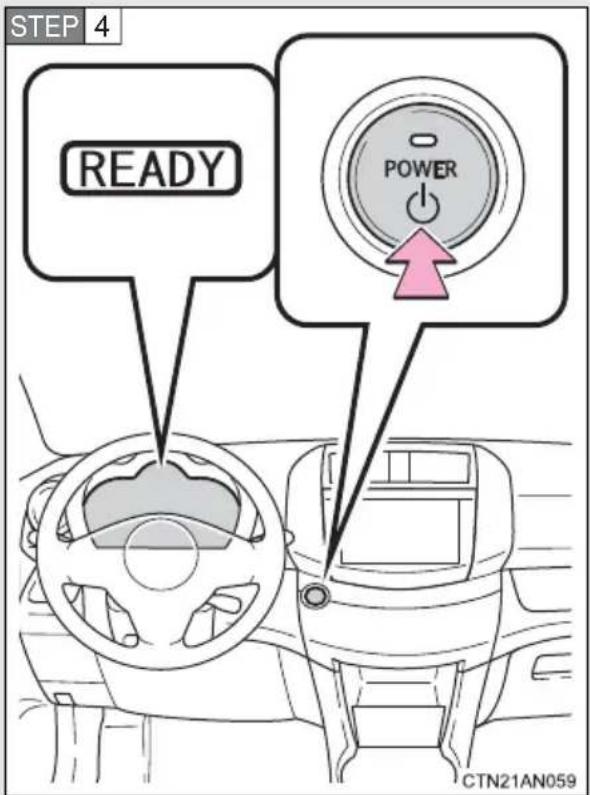
Press the "POWER" switch.
Continue depressing the brake pedal until the EV system is completely started.
The EV system can be started from any "POWER" switch mode.
After a few seconds, the "READY" indicator comes on with a beep sound.
■Stopping the EV system
STEP 1 Depress the brake pedal until the vehicle comes to a complete stop.
STEP 2 Set the parking brake. ( P. 216)
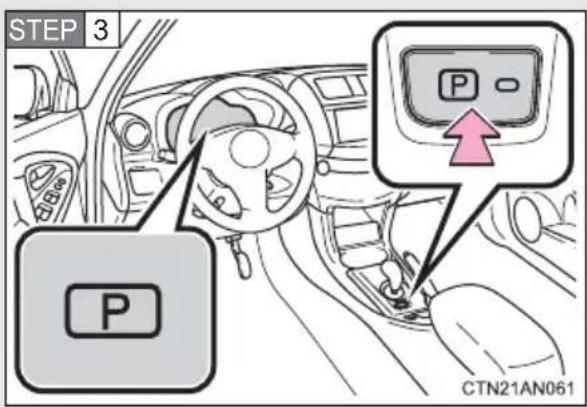
Push the P position switch to shift into P. ( P. 209)
Check that the shift position indicator on the instrument cluster shows P. ( P. 223)
STEP 4 Press the "POWER" switch.
The EV system will stop, and the meter display will turn off (the shift position indicator will turn off a few seconds after the meter display).
STEP 5 Slowly release the brake pedal and check that the indicator on the "POWER" switch is off.
If you stop the EV system without setting the shift position to P, the shift position will be changed to P automatically. You can also change the shift position to P by pushing the P position switch.
■Changing "POWER" switch mode
Modes can be changed by pressing the “POWER” switch with the brake pedal released. (The mode changes each time the switch is pressed.)
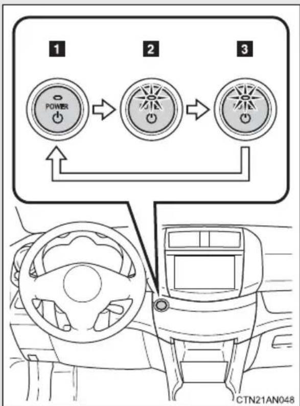
flowchart
graph TD
    A["1 POWER"] --> B["2 POWER"]
    B --> C["3 POWER"]
    C --> D["Top Route"]
    style A fill:#f9f,stroke:#333
    style B fill:#f9f,stroke:#333
    style C fill:#f9f,stroke:#333
    style D fill:#ccf,stroke:#333
1 Off
The emergency flashers can be used.
2 ACCESSORY mode
Some electrical components such as the audio system can be used.
The "POWER" switch indicator turns amber.
3 ON mode
All electrical components can be used.
The "POWER" switch indicator turns amber.
■Auto power off function
If the vehicle is left in ACCESSORY mode for more than an hour with the shift position in P, the "POWER" switch will automatically turn off.
■ Sounds and vibrations specific to a electric vehicle
→P.30
Electronic key battery depletion
→P. 106
■Auto P position function
- If the “POWER” switch is pressed while the EV system is operating and the vehicle is at a complete stop, the “POWER” switch will be turned to OFF, then the shift position will be automatically switched to P.
When turning the “POWER” switch to off while the shift position is not set to P, operate the “POWER” switch while pushing down fully on the brake pedal. Then, release the brake pedal after confirming that the shift position indicator on the instrument cluster shows P.
- If the auto P position function is malfunctioning, it may not be possible to turn the “POWER” switch to off. In this event, the “POWER” switch can be turned to off after applying the parking brake.
Have the vehicle inspected by your Toyota dealer immediately.
■ When the ambient temperature is low, such as during winter driving conditions
Driving power may be limited due to traction battery temperature being low. Follow the instructions on the meter display. If the vehicle has been parked for a long time in low ambient temperatures, it may be necessary to plug in the vehicle to warm-up and charge the traction battery before driving.
■When the P position control system malfunctions
The “POWER” switch will not be able to be turned off. In such a case, the switch can be turned off after applying the parking brake.
Have the vehicle inspected by your Toyota dealer immediately.
■Conditions affecting operation
→P. 104
■Note for the entry function
→P. 105
■If the EV system does not start
● The immobilizer system may not have been deactivated. (→P. 149) Contact your Toyota dealer.
● The charging cable may be connected to the vehicle. (→P. 82)
■When the steering lock cannot be released
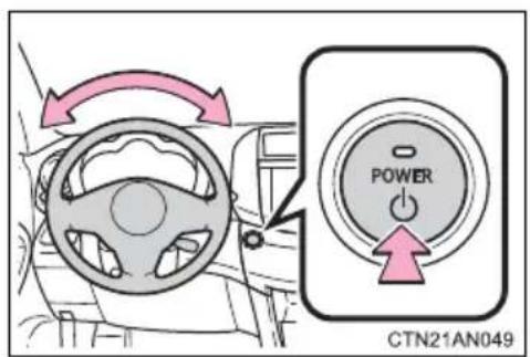
The green indicator light on the "POWER" switch will flash and a message will be shown on the multi-information display. Press the "POWER" switch again while turning the steering wheel left and right.
■When the "POWER" switch indicator flashes in amber
The system may be malfunctioning. Have the vehicle inspected by your Toyota dealer immediately.
If the "READY" indicator does not come on
If the "READY" indicator does not come on when you press the "POWER" switch with the shift position in P and the brake pedal pressed, contact your Toyota dealer immediately.
■If the EV system is malfunctioning
→P. 428
■When the electronic key battery is discharged
→P. 383

CAUTION
■When starting the EV system
Always start the EV system while sitting in the driver's seat. Do not depress the accelerator pedal while starting the EV system under any circumstances. Doing so may cause an accident resulting in death or serious injury.
■Stopping the EV system in an emergency
If you want to stop the EV system in an emergency while driving the vehicle, press and hold the “POWER” switch for more than 2 seconds, or press it briefly 3 times or more in succession. (→P. 479)
However, do not touch the “POWER” switch while driving except in an emergency. Turning the EV system off while driving will not cause loss of steering or braking control, but the power assist to these systems will be lost. This will make it more difficult to steer and brake, so you should pull over and stop the vehicle as soon as it is safe to do so.

NOTICE
■To prevent 12-volt battery discharge
Do not leave the “POWER” switch in ACCESSORY or ON mode for long periods of time without the EV system on.
■When starting the EV system
- Do not depress the accelerator pedal unnecessarily.
- If the EV system becomes difficult to start, have your vehicle checked by your Toyota dealer immediately.
Select a shift position appropriate for the driving conditions.
■Shifting the shift lever
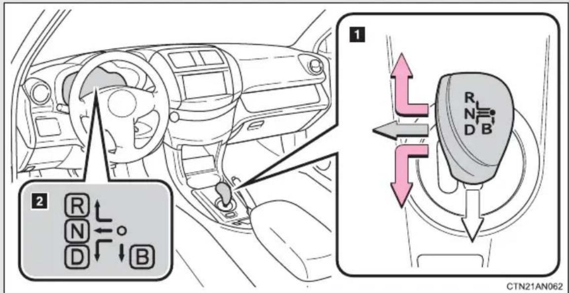
1 Shift lever
Operate the shift lever gently and ensure correct shifting operation.
When shifting to D or R positions, move the shift lever along the shift gate.
To shift to N position, slide the shift lever to the left and hold it. The shift position will change to N.
Shifting to B is only possible when shift position D is selected.

The shift lever always returns to this original position after a shifting operation.
When shifting from P to N, D or R; from D to R; or from R to D, ensure that the brake pedal is being depressed and the vehicle is stationary.
2 Shift position indicator
The position of the frame on the shift position indicator changes in accordance with the current shift position.
When a shift position other than D or B is selected, the arrow toward B and B position indicator disappear from the shift position indicator.
When selecting the shift position, make sure that the shift position has been changed to the desired position by checking the shift position indicator provided on the instrument panel.
Shift position purpose
| Shift position Function | |
| P Parking the vehicle/starting the EV system | |
| R Reversing | |
| N Neutral | |
| D Normal driving | |
| B | Applying regenerative braking when driving down hills or on steep slopes |
■SPORT mode
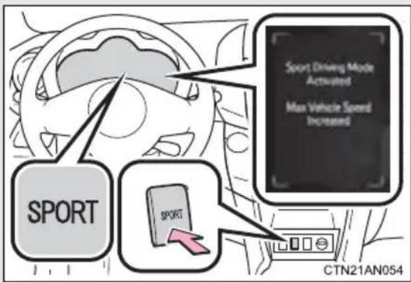
By increasing the motor's output when compared to normal mode, the vehicle's acceleration power and maximum speed is increased. This mode provides a more dynamic driving experience.
When the SPORT mode button is pressed, the SPORT mode indicator comes on and a message is shown on the multi-information display.
When the SPORT mode button is pressed again: the indicator turns off, the message "Sport Driving Mode Deactivated Max Vehicle Speed Decreased" is shown on the multi-information display and normal mode is returned to.
P position switch
■When shifting the shift position to P
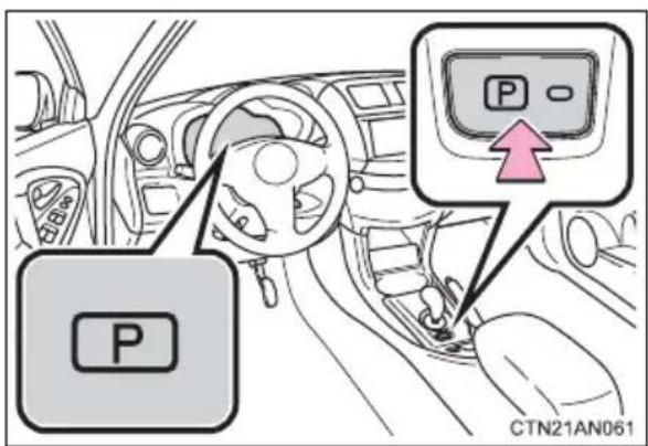
Fully stop the vehicle and set the parking brake, and then press the P position switch.
When the shift position is changed to P, the indicator on the P position switch illuminates.
Check that the shift position indicator on the instrument cluster shows P.
■Shifting the shift position from P to other positions
●While depressing the brake pedal firmly, operate the shift lever. If the shift lever is operated without depressing the brake pedal, the buzzer will sound and the shifting operation will be disabled.
- When selecting a shift position, make sure that the shift position has been changed to the desired position by checking the shift position indicator provided on the instrument cluster.
●The shift position cannot be changed from P to B directly.
For the shift positions
- When the "POWER" switch is off, the shift position cannot be changed.
- When the “POWER” switch is in ON mode (the EV system is not operating), the shift position can only be changed to N. The shift position will be changed to N even if the shift lever is shifted to D or R and held in that position.
- When the “READY” indicator is on, the shift position can be changed from P to D, N or R.
- When the “READY” indicator is flashing, the shift position cannot be changed from P to another position even if the shift lever is operated. Wait until the “READY” indicator changes from a flashing to a solid light, and then operate the shift lever again.
●The shift position can only be changed to B directly from D.
In addition, if the shift position is changed in any of the following situations, the buzzer will sound and the shifting operation will be disabled or the shift position will automatically change to N. When this happens, select an appropriate shift position.
● Situations where the shifting operation will be disabled:
- When the shift position is changed from P to another position while the charging cable is connected to the vehicle.
- When the shift position is changed from P to another position without depressing the brake pedal.
- When the shift position is changed from P or N to B.
- Situations where the shift position will automatically change to N:
- When the P position switch is pressed while the vehicle is running. *1
- When shift position R is selected when the vehicle is moving forward. ^* ^2
- When shift position D is selected when the vehicle is moving in reverse. ^*3
- When the shift position is changed from R to B.
*1: Shift position may be changed to P when driving at extremely low speeds.
^*2 : Shift position may be changed to R when driving at low speeds.
*3: Shift position may be changed to D when driving at low speeds.
■Reverse warning buzzer
When shifting into R, a buzzer will sound to inform the driver that the shift position is in R.
■Automatically P position selection function
When the “POWER” switch is in ON mode while the shift position is in a position other than P and the vehicle is stopped completely, pressing the “POWER” switch will cause the automatic P position selection function to operate together with the “POWER” switch being turned to off.
If the shift position cannot be shifted from P
There is a possibility that the 12-volt battery is discharged. Check the 12-volt battery in this situation. ( P. 470)
■ Using regenerative braking
When shift position D or B is selected, releasing the accelerator pedal will apply regenerative braking.
The vehicle can be accelerated even when shift position B is selected.
If the brake pedal is depressed very quickly after the accelerator pedal is released, the amount of regenerated energy displayed on the EV system indicator ( P. 221) may be less than expected. This is not a malfunction, and will probably not feel any different than usual. The amount of regenerated energy will return to expected when the brake pedal is released and depressed again.
■If the system malfunctions
The following situations indicate a problem with the system.
Immediately stop the vehicle in a safe place and contact your Toyota dealer.
● All frames of the shift position indicators in the instrument cluster flash.
● The parking system error message appears on the multi-information display.
●The instrument cluster does not come on when the "POWER" switch is in ON mode.
■When sport mode is selected
When sport mode is selected, the “SPORT” indicator will come on and the speed meter circumference ring and some instrument panel lights will turn from blue to red.
In some cases, sport mode will not be available. A buzzer will sound and "Sport Driving Mode Not Available" is shown on the multi-information display. If already driving in sport mode, the vehicle will automatically change back to normal mode.
Alarms
The following table describes circumstances and correction procedures when only alarms sound.
| Alarm Situation | Correction procedure | |
| Interior alarm sounds once | The driver attempts to shift out of the P position without depressing the brake pedal. | The transmission will not move out of the P position. Depress the brake pedal before attempting to shift again. |
| The P position switch is pressed while the vehicle is moving. | The transmission will automatically be set to the N position. Select the appropriate position. | |
| The driver attempts to shift to the R position while the vehicle is in forward motion. | ||
| The driver attempts to shift to the D position while the vehicle is in rearward motion. | ||
| The driver attempts to shift to the B position while in the R position. | ||
| Alarm Situation Correction procedure | ||
| Interior alarm sounds once | The driver attempts to shift to the B position while in the P or N position. | The transmission will not move out of the P or N position. Select the appropriate position. |
| The driver attempts to shift from P position to another position during charging. | The transmission will not move out of the P position. Disconnect the charging cable, start the EV system, and shift again. | |
| Interior alarm beep sounds and warning message* | If the driver's door is opened while the transmission is in N, D or B. | Push the P position switch. |
*: Follow the warning message displayed.

CAUTION
■To avoid an accident
Do not hang objects on or attach objects to the shift lever.
Doing so may cause the shift lever to move and the shift position to change.
For the shift lever
Do not remove the shift lever knob or use anything but a genuine Toyota shift lever knob. Also, do not hang anything on the shift lever.
Doing so could prevent the shift lever from returning to position, causing unexpected accidents to occur when the vehicle is in motion.
■P position switch
Do not press the P position switch while the vehicle is moving.
If the P position switch is pressed when driving at very low speeds (for example, directly before stopping the vehicle), the vehicle may stop suddenly when the shift position switches to P, which could lead to an accident.

NOTICE
■ Situations where P position control system malfunctions are possible
If any of the following situations occur, P position control system malfunctions are possible.
Immediately stop the vehicle in a safe place on level ground, apply the parking brake, and then contact your Toyota dealer.
- When the "P Lock Malfunction" warning message appears on the multi-information display. (→P. 429)
- When the shift position symbols (such as P and R) are extinguished and the frames surrounding the shift position symbols are flashing on the shift position indicator.
- When the shift position indicator remains off.
Notes regarding shift lever and P position switch operation
Avoid repeatedly operating the shift lever and P position switch in quick succession.
The system protection function may activate and it will not be temporarily possible to shift the shift position other than P. If this happens, please wait for a while before attempting to change the shift position again.
The turn signal lever can be used to show the following intentions of the driver:
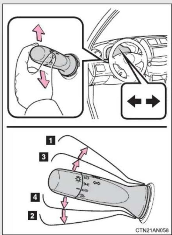
1 Right turn
2 Left turn
3 Lane change to the right (push and hold the lever partway)
The right hand signals will flash until you release the lever.
4 Lane change to the left (push and hold the lever partway)
The left hand signals will flash until you release the lever.
■Turn signals can be operated when
The "POWER" switch is in ON mode.
■If the indicators flash faster than usual
Check that a light bulb in the front or rear turn signal lights has not burned out.
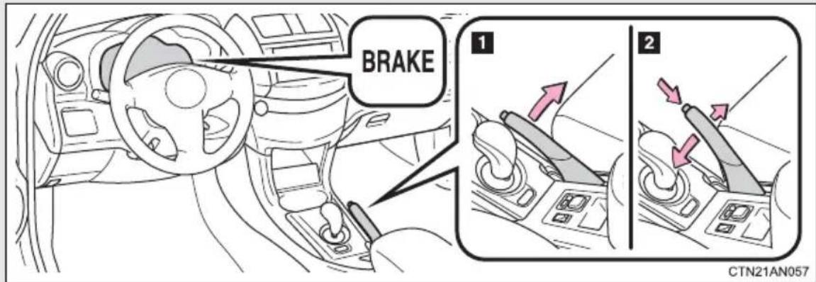
To set the parking brake, fully pull the parking brake lever while depressing the brake pedal.
2 To release the parking brake, slightly raise the lever and lower it completely while pressing the button.
■Parking brake engaged warning buzzer
→P. 433
■Usage in winter time
→P. 268

NOTICE
Before driving
Fully release the parking brake.
Driving the vehicle with the parking brake set will lead to brake components overheating, which may affect braking performance and increase brake wear.
■When parking the vehicle
Before you leave the vehicle, set the parking brake, push the P position switch and make sure that the vehicle does not move.
2-1. Driving procedures
Horn
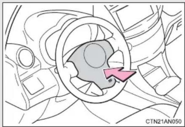
natural_image
Diagram of a car steering wheel with a highlighted directional arrow (no text or symbols)To sound the horn, press on or close to the mark.
■After adjusting the steering wheel
Make sure that the steering wheel is securely locked.
The horn may not sound if the steering wheel is not securely locked.
(→P. 140)
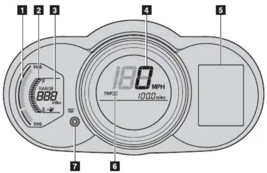
CTN22AN069
The following gauges, meters and displays illuminate when the "POWER" switch is in ON mode.
1 EV System Indicator
Displays the EV system output or regeneration level.
2 SOC (State of Charge) gauge
Displays the amount of charge remaining in the traction battery.
3 Driving range
Displays an estimated drivable distance according to the climate setting and the amount of charge remaining in the traction battery.
(→P. 30, 276)
4 Speedometer
Displays the vehicle speed.
5 Multi-information display
Presents the driver with a variety of driving-related data ( P. 227)
6 Odometer/trip meter
Odometer
Displays the total distance the vehicle has been driven.
Trip meter
Displays the distance the vehicle has been driven since the meter was last reset. Trip meters A and B can be used to record and display different distances independently.
7 Display change button
Performs odometer, trip meter and meter display customization.
While the trip meter is being displayed: Pressing and holding the button will reset the trip meter.
While the odometer is being displayed: Pressing and holding the button enables Eco Driving Indicator Light and the turn-by-turn navigation to be activated or deactivated.
Instrument panel light control
The brightness of the instrument panel lights can be adjusted.
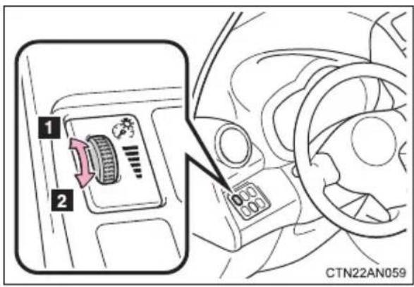
1 Brighter
2 Darker
Eco Driving Indicator Light and turn-by-turn navigation display customization
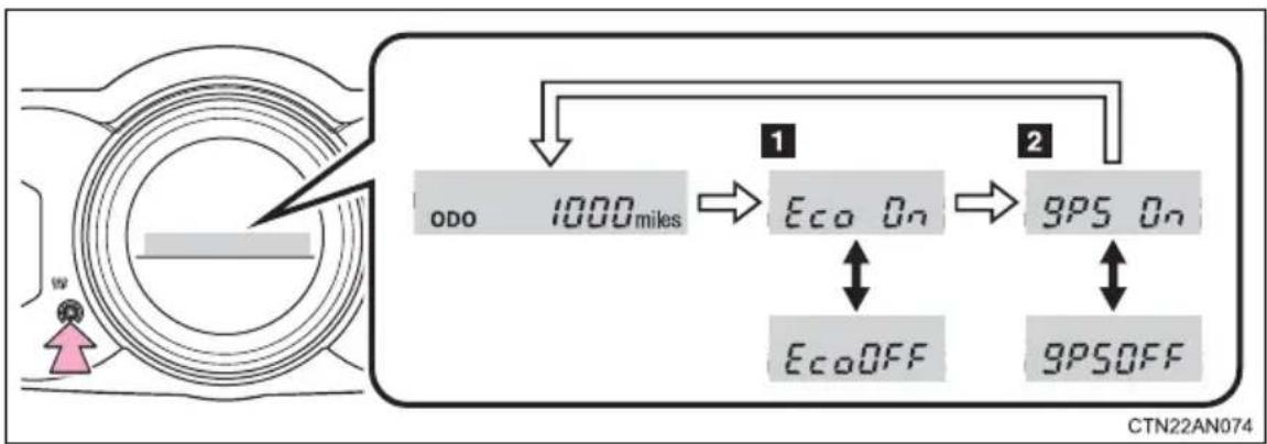
flowchart
graph TD
    A["ODO 1000 miles"] --> B["Eco On"]
    B --> C["GPS On"]
    D["EcoOFF"] <--> B
    E["GPSOFF"] <--> C
    F["Start"] --> G["End"]
While the odometer is being displayed, customization can be performed by pressing and holding the display change button.
1 Each time the display change button is pressed, ECO Driving Indicator Light display is activated or deactivated.
If OFF is selected, the Eco Driving Indicator Light will not be displayed.
2 Each time the display change button is pressed, the turn-by-turn navigation is activated or deactivated.
If OFF is selected, the turn-by-turn navigation display will not be displayed.
When settings have been completed, press and hold the display change button until the odometer is displayed.
■The meters and display illuminate when
The "POWER" switch is in ON mode.
■EV System Indicator
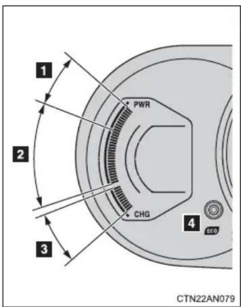
1 Power area Shows that an Eco-friendly driving range is being exceeded (during full power driving etc.)
2 Eco area Shows that the vehicle is being driven in an Eco-friendly manner.
3 Charge area Shows that energy is being recovered via the regenerative charging.
4 Eco Driving Indicator During Eco-friendly acceleration operation (Eco driving), Eco Driving Indicator Light will turn on. When the accelerator pedal is depressed excessively, and when the vehicle is stopped, the light turns off.
Eco Driving Indicator Light will not operate in the following conditions:
●The driving mode is set to SPORT mode.
●The vehicle speed is approximately 80 mph (130 km/h) or higher.
Eco Driving Indicator Light can be activated or deactivated. ( P. 220)
- By keeping the indicator needle within Eco area, more Eco-friendly driving can be achieved.
- Charge area indicates regeneration* status. Regenerated energy will be used to charge the traction battery.
*: When used in this manual, “regeneration” refers to the conversion of energy created by the movement of the vehicle into electrical energy.
■The brightness of the instrument panel lights
When the tail lights are turned on, the meter's brightness will be reduced slightly unless the meter brightness level adjustment is set to the brightest setting.
If the tail lights are turned on when the surroundings are dark, the meter's brightness will reduce slightly. However, when the surroundings are bright, such as during the daytime, the meter's brightness will not be reduced even if the tail lights are turned on.
2-2. Instrument cluster
Indicators and warning lights
The indicator and warning lights on the instrument cluster and center panel inform the driver of the status of the vehicle's various systems.
Instrument cluster
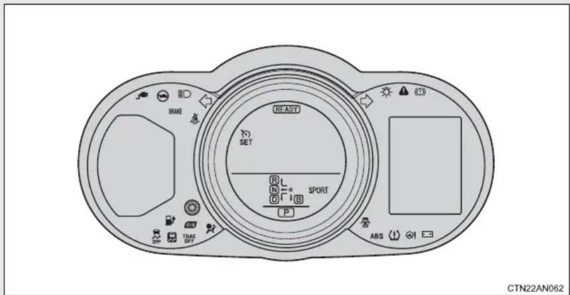
Center panel
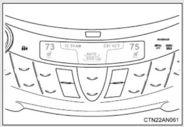
■Outside left of vehicle
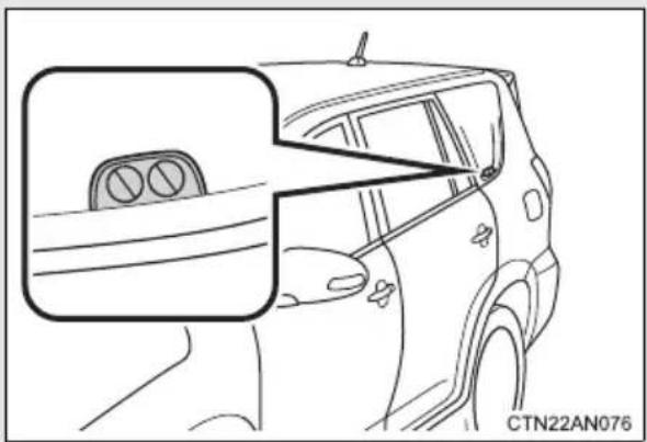
natural_image
Line drawing of a car showing the side window and rear door, with no visible text or symbols.Indicators
The indicators inform the driver of the operating state of the vehicle's various systems.
Turn signal indicator ( P. 215)
Headlight indicator ( P. 234)
Headlight high beam indicator ( P. 235)
Slip indicator ( P. 251, 256)
VSC OFF indicator ( P. 252)
Security indicator ( P. 149)
(Center panel)
Cruise control indicator ( P. 243)
Cruise control set indicator ( P. 243)
"TRAC OFF" indicator (→P. 252, 477)
Plug-in indicator ( P. 59)
(green)

SPORT mode indicator ( P. 208)

Eco Driving Indicator Light ( P. 221)
"READY" indicator (→P. 200)
"AIR BAG ON" and "AIR BAG OFF" indicator (→P. 166)
(Center panel)
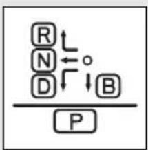
flowchart
graph TD
    R --> N
    N --> D
    D --> B
    B --> O
    O --> R
    P[" "]
Shift position indicators ( P. 206)
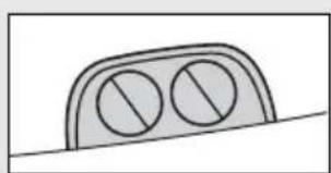
natural_image
Simple line drawing of a two-circular object on a flat surface (no text or symbols)Charging indicator ( P. 59)
(Outside left of the vehicle)
*1: These lights turn on when the “POWER” switch is turned to ON mode to indicate that a system check is being performed. They will turn off after the EV system is started, or after a few seconds. There may be a malfunction in a system if a light does not come on, or if the lights do not turn off. Have the vehicle inspected by your Toyota dealer for details.
^*2 : The light flashes to indicate that the system is operating.
■Warning lights
Warning lights inform the driver of malfunctions in any of the vehicle's systems. (→P. 417)
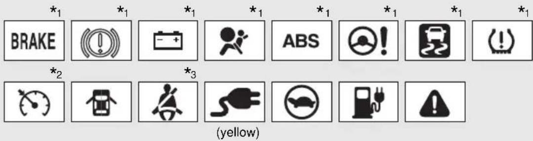
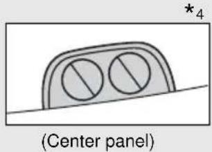
*1: These lights turn on when the “POWER” switch is turned to ON mode to indicate that a system check is being performed. They will turn off after the EV system is started, or after a few seconds. There may be a malfunction in a system if a light does not come on, or if the lights do not turn off. Have the vehicle inspected by your Toyota dealer for details.
*2: The light flashes to indicate a malfunction.
*3: Driver's/front passenger's seat belt reminder light
*4: Both lights flash quickly for 10 seconds to indicate that the system is malfunctioning.

CAUTION
If a safety system warning light does not come on
Should a safety system light such as the ABS and SRS airbag warning light not come on when you start the EV system, this could mean that these systems are not available to help protect you in an accident, which could result in death or serious injury. Have the vehicle inspected by your Toyota dealer immediately if this occurs.
The multi-information display presents the driver with a variety of driving-related data.
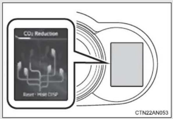
- Trip information (→P. 229)
Displays driving range, power consumption and other cruising-related information.
●Warning messages (→P. 427)
Automatically displayed when a malfunction occurs in one of the vehicle's systems.
■Display contents
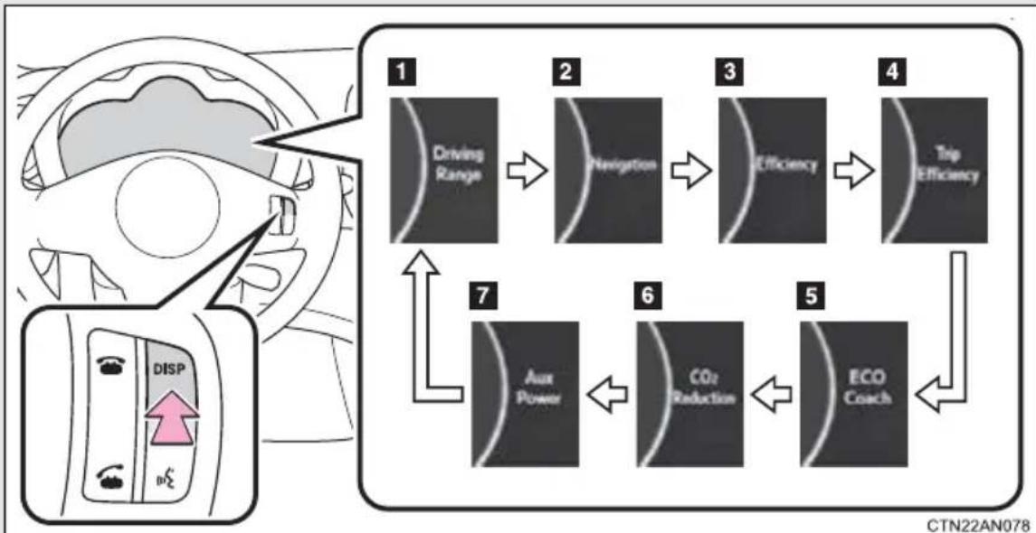
flowchart
graph TD
    A["Driving Range"] --> B["Navigation"]
    B --> C["Efficiency"]
    C --> D["Trip Efficiency"]
    D --> E["Aux Power"]
    E --> F["CO2 Reduction"]
    F --> G["ECO Coach"]
    G --> H["DISP"]
Each time the “DISP” switch is pressed, the menu screen changes. When the desired menu screen is displayed, stop pressing the “DISP” switch. The details screen will soon be displayed.
| Trip information contents Switching display items | |
| 1 Driving range | Press the “DISP” switch. |
| 2 Turn-by-turn navigation* | |
| 3 Efficiency | |
| 4 Trip efficiency | |
| 5 ECO coach | |
| 6 CO2 reduction | |
| 7 Aux power | |
*: Not shown when no destination is set or when the turn-by-turn navigation display is not activated. (→P. 220, 231).
Trip information
■Driving range
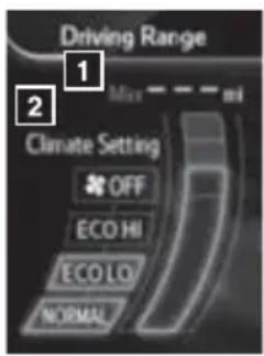
Displays an estimated driving range according to the amount of charge remaining in the traction battery and air conditioning settings.
1 Displays what the estimated maximum driving range is with the air conditioning system off according to the amount of charge remaining in the traction battery.
2 Displays the amount the estimated maximum driving range is shortened according to current air conditioning mode.
The climate setting is linked to the air conditioning system, and changes according to air conditioning settings. ( P. 276)
The estimated maximum driving range is only an estimate. According to driving conditions, the actual driving range may differ. Keep early charging in mind.
The driving range according to current air conditioning mode is displayed in the left section of the instrument cluster. ( P. 218)
Efficiency
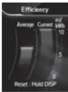
Displays average power consumption and current power consumption.
Average power consumption
Displays the average power consumption since the function was reset.
The function can be reset by pressing the "DISP" button for longer than 1 second when the average power consumption/current power consumption is displayed.
Current power consumption
Displays current power consumption.
Trip efficiency
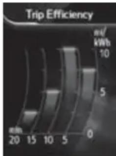
bar
Trip Efficiency | Time (min) | Efficiency (w/kWh) | |---|---| | 20 | 0 | | 15 | 2 | | 10 | 4 | | 5 | 6 | | 0 | 8 |Displays the average power consumption in intervals of 5 minutes. Current power consumption is simultaneously displayed, allowing it to be compared with previous power consumption rates.
ECO coach
Evaluates the level of eco friendly driving according to acceleration, speed and braking. An overall score is also displayed.
Displays the average score up until now when the EV system is turned off. ( P. 232)
CO _2 reduction

In accordance with the amount of charging performed since the function was last reset, the amount of CO_2 reduction when compared to a conventional gasoline vehicle is displayed as a growing tree.
The function can be reset by pressing the "DISP" button for longer than 1 second when the CO_2 reduction screen is displayed.
AUX Power
Displays average 12-volt battery power consumption and current 12-volt battery power consumption.
Average 12-volt battery consumption
Displays the average 12-volt battery power consumption since the function was reset.
The function can be reset by pressing the "DISP" button for longer than 1 second when the Aux Power screen is displayed.
Current 12-volt battery power consumption
Displays the current 12-volt battery power consumption.
Turn-by-turn navigation\*
Displays a notification of upcoming intersections during navigation system route guidance
Turn-by-turn can be activated or deactivated. ( P. 220)
*: For more details on route guidance settings, refer to "Navigation System Owner's Manual".
Ending screen
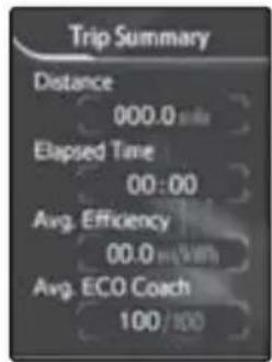
CTN22AN054
When the EV system is turned off, drive information data since the system was started is displayed after the ending animation.
When the driver's door is closed, the screen turns off.
ECO coach
●As the accelerator pedal is not depressed, the driven distance using cruise control is not included in the ECO coach.
As the eco coach evaluation differs according to driving conditions and environmental factors, in some cases it may not be linked to power consumption.
■Liquid crystal display
Small spots or light spots may appear on the display. This phenomenon is characteristic of liquid crystal displays, and there is no problem continuing to use the display.
■ Customization that can be configured at Toyota dealer
Setting of available languages can be changed.
(Customizable features → P. 500)

CAUTION
ECO score
ECO score should be used as a guide only. Always drive safely in accordance with road and traffic conditions.

NOTICE
■The multi-information display at low temperatures
Allow the interior of the vehicle to warm up before using the liquid crystal information display. At extremely low temperatures, the information display monitor may respond slowly, and display changes may be delayed.
The headlights can be operated manually or automatically.
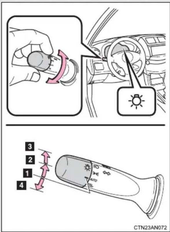
1 AUTO The headlights, parking lights and daytime running lights turn on and off automatically. (When the "POWER" switch is in ON mode)
2 00 The side marker, parking, tail, license plate, daytime running lights and instrument panel lights turn on.
3 The headlights and all lights listed above (except daytime running lights) turn on.
4 DRL OFF The daytime running lights turn off.
Turning on the high beam headlights
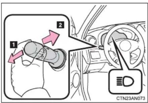
1 With the headlights on, push the lever away from you to turn on the high beams.
Pull the lever toward you to the center position to turn the high beams off.
2 Pull the lever toward you and release it to flash the high beams once.
You can flash the high beams with the headlights on or off.
Manual headlight leveling dial
The level of the headlights can be adjusted according to the number of passengers and the loading condition of the vehicle.
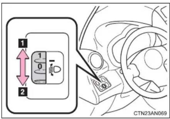
1 Raises the level of the headlights
2 Lowers the level of the headlights
■Guide to dial settings
| Occupancy and luggage load conditions | Dial position | |
| Occupants Luggage load | ||
| Driver None 0 | ||
| Driver and front pas-senger | None 0 | |
| All seats occupied None 1 | ||
| All seats occupied Full luggage loading 2 | ||
| Driver Full luggage loading 1 | ||
■Daytime running light system
● To make your vehicle more visible to other drivers, the daytime running lights turn on automatically whenever the EV system is started and the parking brake is released. Daytime running lights are not designed for use at night.
- Compared to turning on the headlights, the daytime running light system offers greater durability and consumes less electricity, so it can help improve power consumption.
■Headlight control sensor
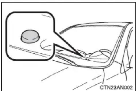
The sensor may not function properly if an object is placed on the sensor, or anything that blocks the sensor is affixed to the windshield.
Doing so interferes with the sensor detecting the level of ambient light and may cause the automatic headlight system to malfunction.
■Automatic light off system
The headlights and tail lights turn off 30 seconds after driver's door is opened and closed if the "POWER" switch has been turned to ACCESSORY
mode or turned off. (The lights turn off immediately if on the key is pressed twice after all the doors are closed.)
To turn the lights on again, turn the "POWER" switch to ON mode, or turn the
headlight switch off and then back to 00
■ Customization that can be configured at Toyota dealer
Settings (e.g. light sensor sensitivity) can be deactivated.
(Customizable features → P. 500)
NOTICE
■To prevent 12-volt battery discharge
Do not leave the lights on longer than necessary when the EV system is off.
When "INT" is selected, the wiper interval can be adjusted for intermittent operation.
The wiper operation is selected by moving the lever as follows.
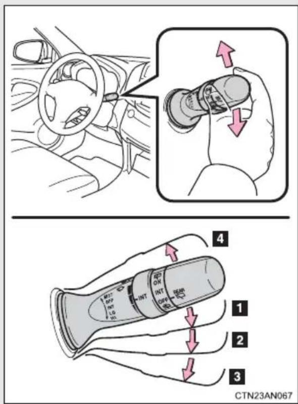
1 INT Intermittent wind-shield wiper operation
2 LO Low speed wind-shield wiper operation
3 HI High speed wind-shield wiper operation
4 MIST Temporary operation
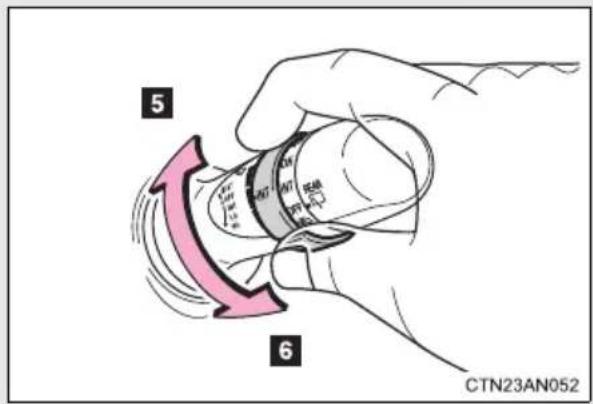
5 Increases the intermittent windshield wiper frequency
6 Decreases the intermittent windshield wiper frequency
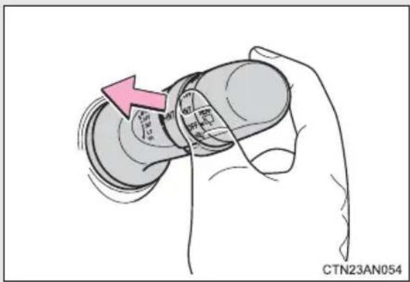
Wash/wipe operation
The wipers will automatically operate a couple of times after the washer squirts.
■The windshield wipers and washer can be operated when
The "POWER" switch is in ON mode.
■If no windshield washer fluid sprays
Check that the washer nozzles are not blocked and if there is washer fluid in the windshield washer fluid reservoir.

CAUTION
■Caution regarding the use of washer fluid
When it is cold, do not use the washer fluid until the windshield becomes warm. The fluid may freeze on the windshield and cause low visibility. This may lead to an accident, resulting in death or serious injury.

NOTICE
■When the windshield is dry
Do not use the wipers, as they may damage the windshield.
■When the washer fluid tank is empty
Do not operate the switch continually as the washer fluid pump may overheat.
■When a nozzle becomes blocked
In this case, contact your Toyota dealer.
Do not try to clear it with a pin or other object. The nozzle will be damaged.
2-3. Operating the lights and wipers
Rear window wiper and washer
The wiper operation is selected by moving the lever as follows:
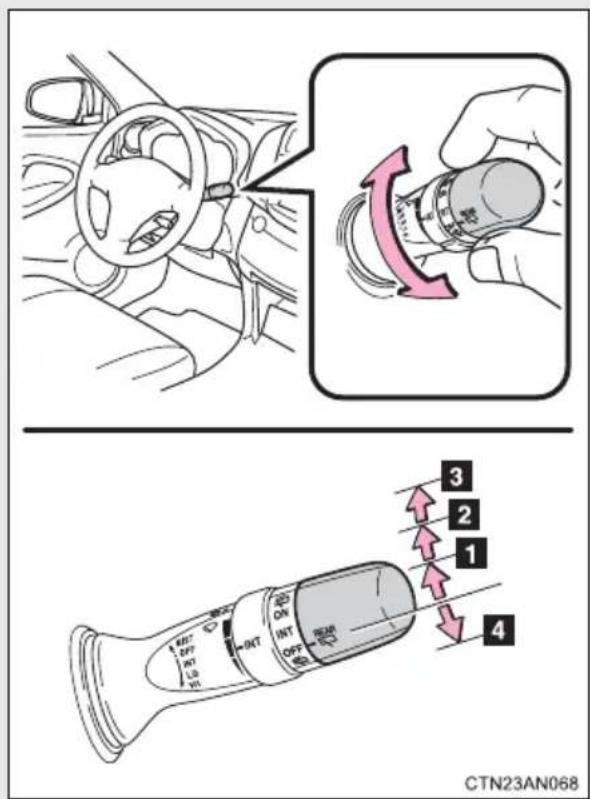
1 INT Intermittent window wiper operation
2 ON Normal window wiper operation
3 Washer/wiper dual operation
4 Washer/wiper dual operation
■The rear window wiper and washer can be operated when
The "POWER" switch is in ON mode.
■If no washer fluid sprays
Check that the washer nozzle is not blocked if there is washer fluid in the washer fluid reservoir.

NOTICE
■When the rear window is dry
Do not use the wipers, as they may damage the rear window.
■When the washer fluid tank is empty
Do not operate the switch continually as the washer fluid pump may overheat.
When a nozzle is blocked
Do not try to clear it with a pin or other object. The nozzle will be damaged.
Use the cruise control to maintain a set speed without depressing the accelerator pedal.
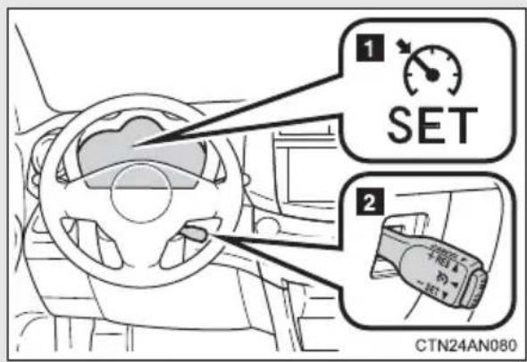
1 Indicators
2 Cruise control switch
■Setting the vehicle speed
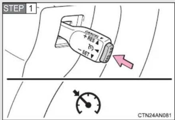
Press the "ON-OFF" button to activate the cruise control.
Cruise control indicator will come on.
Press the button again to deactivate the cruise control.
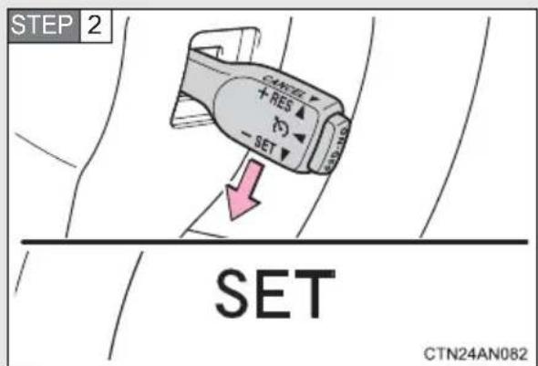
Accelerate or decelerate the vehicle to the desired speed, and push the lever down to set the speed.
"SET" indicator will come on.
The vehicle speed at the moment the lever is released becomes the set speed.
■Adjusting the set speed
To change the set speed, operate the lever until the desired set speed is obtained.
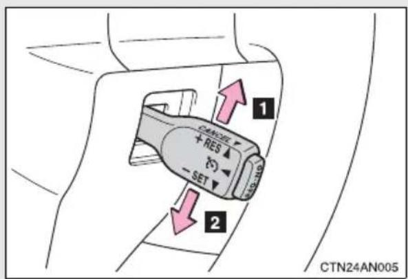
1 Increase the speed
2 Decrease the speed
Hold the lever until the desired speed setting is obtained.
Fine adjustment: Momentarily move the lever in the desired direction.
Large adjustment: Hold the lever in the desired direction.
The set speed will be increased or decreased as follows:
Fine adjustment: By approximately 1 mph (1.6 km/h) each time the lever is operated.
Large adjustment: The set speed can be increased or decreased continually until the lever is released.
■ Canceling and resuming the constant speed control
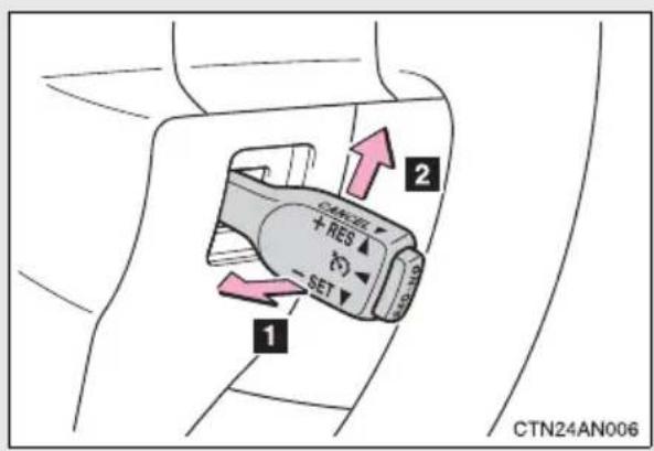
1 Pulling the lever toward you cancels the constant speed control.
The speed setting is also canceled when the brakes are applied.
2 Pushing the lever up resumes the constant speed control.
Resuming is available when the vehicle speed is more than approximately 25 mph (40 km/h).
■ Cruise control can be set when
●The shift position is in D.
● Vehicle speed is above approximately 25 mph (40 km/h) and below the maximum vehicle speed.
Maximum vehicle speed differs according to driving mode. ( P. 208)
■Accelerating after setting the vehicle speed
●The vehicle can be accelerated normally. After acceleration, the set speed resumes.
● Even without canceling the cruise control, the set speed can be increased by first accelerating the vehicle to the desired speed and then pushing the lever down to set the new speed.
■Automatic cruise control cancelation
Cruise control will stop maintaining the vehicle speed in any of the following situations.
●Actual vehicle speed falls more than approximately 10 mph (16 km/h) below the preset vehicle speed.
At this time, the memorized set speed is not retained.
●Actual vehicle speed is below approximately 25 mph (40 km/h).
●VSC is activated.
If the cruise control indicator light flashes and “Check Cruise Control System” is shown on the multi-information display
There may be a malfunction in the cruise control system. Have the vehicle inspected by your Toyota dealer.

CAUTION
■To avoid operating the cruise control by mistake
Switch the cruise control off using the "ON-OFF" button when not in use.
■Situations unsuitable for cruise control
Do not use cruise control in any of the following situations.
Doing so may result in loss of control and could cause an accident resulting in death or serious injury.
In heavy traffic
● On roads with sharp bends
●On winding roads
●On slippery roads, such as those covered with rain, ice or snow
●On steep hills
Vehicle speed may exceed the set speed when driving down a steep hill.
2-4. Using other driving systems Rear view monitor system
The rear view monitor system assists the driver by displaying an image of the area behind the vehicle. The image is displayed in reverse on the screen. This reversed image is a similar image to the one on the inside rear view mirror.
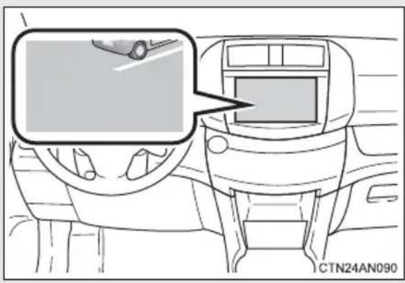
natural_image
Interior view of a car dashboard with steering wheel and touchscreen display (no text or symbols visible)The rear view image is displayed when the shift position is in R.
If the shift position is changed out of R, the screen returns to the previous one.
■Displayed area
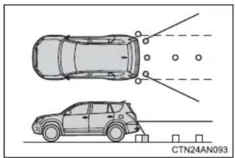
The area covered by the camera is limited. Objects that are close to either corner of the bumper or under the bumper cannot be seen on the screen.
The area displayed on the screen may vary according to vehicle orientation or road conditions.
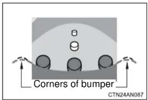
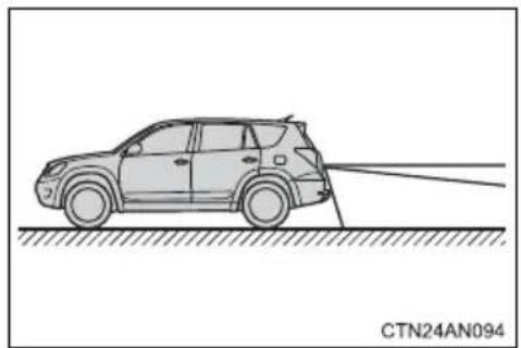
natural_image
Line drawing of a car on a road with a sensor or projection line, no text or symbols present■Rear view monitor system camera
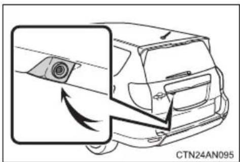
natural_image
Diagram of a car's rearview and side profile showing airflow direction (no text or symbols)In the following cases, it may become difficult to see the images on the screen, even when the system is functioning correctly:
●The vehicle is in a dark area, such as at night.
●The temperature near the lens is extremely high or low.
●Water droplets are on the camera lens or humidity is high, such as when it rains.
●Foreign matter, such as snow or mud, adheres to the camera lens.
●The camera has scratches or dirt on it.
●The sun or headlights are shining directly into the camera lens.
Smear effect
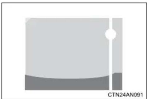
natural_image
Abstract geometric shape with a white circle and gray base, no text or symbols presentIf a bright light, such as sunlight reflected off the vehicle body, is picked up by the camera, a smear effect* characteristic to the camera may occur.
*: Smear effect — A phenomenon that occurs when a bright light is picked up by the camera; when transmitted by the camera, the light source appears to have a vertical streak above and below it.

CAUTION
When using the rear view monitor system, observe the following precautions to avoid an accident that could result in death or serious injuries:
●Never depend solely on the monitor system when reversing.
● Always check visually and with the mirrors to confirm your intended path is clear.
● Depicted distances between objects and flat surfaces differ from actual distances.
- Do not use the system if the back door is open.
■Conditions which may affect the rear view monitor system
- If the back of the vehicle has been hit, the camera's position and mounting angle may have changed. Have the vehicle inspected by your Toyota dealer.
●Rapid temperature changes, such as when hot water is poured on the vehicle in cold weather, may cause the system to function abnormally. - If the camera lens is dirty, it cannot transmit a clear image. Rinse with water and wipe with a soft cloth. If extremely dirty, wash with a mild cleanser and rinse.
●The displayed image may be darker and moving images may be slightly distorted when the system is cold.
● As the camera has a water proof construction, do not detach, disassemble or modify it. This may cause incorrect operation. - Do not allow organic solvent, car wax, window cleaner or glass coat to adhere to the camera. If this happens, wipe it off as soon as possible.
- If the temperature changes rapidly, such as when hot water is poured on the vehicle in cold weather, the system may not operate normally.
- When the camera is used under fluorescent lights, sodium lights, or mercury lights, the lights and the illuminated areas may appear to flicker.
- When washing the vehicle, do not apply intensive bursts of water to the camera or camera area. Doing so may result in the camera malfunctioning.
To help enhance driving safety and performance, the following systems operate automatically in response to various driving situations. Be aware, however, that these systems are supplementary and should not be relied upon too heavily when operating the vehicle.
■ABS (Anti-lock Brake System)
Helps to prevent wheel lock when the brakes are applied suddenly, or if the brakes are applied while driving on a slippery road surface
Brake assist
Generates an increased level of braking force after the brake pedal is depressed, when the system detects a panic stop situation
■VSC (Vehicle Stability Control)
Helps the driver to control skidding when swerving suddenly or turning on slippery road surfaces
■TRAC (Traction Control)
Helps to maintain drive power and prevent the drive wheels from spinning when starting the vehicle or accelerating on slippery roads
■Hill-start assist control
→P. 256
EPS (Electric Power Steering)
Employs an electric motor to reduce the amount of effort needed to turn the steering wheel
When the TRAC/VSC/ABS systems are operating
The slip indicator light will flash while the TRAC/VSC/ABS systems are operating.
Disabling the TRAC system
If the vehicle gets stuck in mud, dirt or snow, the TRAC system may reduce power from the EV system to the wheels. Pressing 📄 to turn the system off may make it easier for you to rock the vehicle in order to free it.
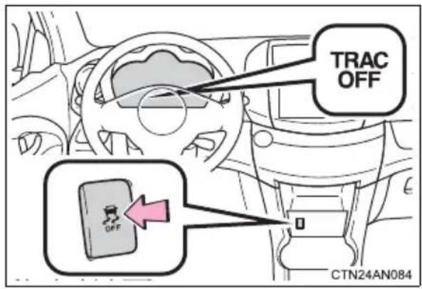
To turn the TRAC system off, quickly press and release OFF
The "TRAC OFF" indicator light will come on.
Press again to turn the sys- tem back on.
■Turning off both TRAC and VSC systems
To turn the TRAC and VSC systems off, press and hold for more than 3 seconds while the vehicle is stopped.
The "TRAC OFF" indicator light and VSC OFF indicator light will come on.
Press again to turn the systems back on.
■ When the “TRAC OFF” indicator light comes on even if the VSC OFF switch has not been pressed
TRAC cannot be operated. Contact your Toyota dealer.
■ Sounds and vibrations caused by the ABS, brake assist, TRAC, and VSC systems
● A sound may be heard from the motor compartment when the EV system is started or just after the vehicle begins to move, if the brake pedal is depressed forcefully or repeatedly, or 1 - 2 minutes after the EV system is stopped. This sound does not indicate that a malfunction has occurred in any of these systems.
● Any of the following conditions may occur when the above systems are operating. None of these indicates that a malfunction has occurred.
- Vibrations may be felt through the vehicle body and steering.
- A motor sound may be heard after the vehicle comes to a stop.
- The brake pedal may pulsate slightly after the ABS is activated.
- The brake pedal may move down slightly after the ABS is activated.
EPS operation sound
When the steering wheel is operated, a motor sound (whirring sound) may be heard. This does not indicate a malfunction.
■Reactivation of the TRAC/VSC systems
Turning off the EV system after turning off the TRAC/VSC systems will automatically reactivate them.
■Reactivation of the TRAC system linked to vehicle speed
When only the TRAC system is turned off, the TRAC system will turn on when vehicle speed increases. However, when both TRAC and VSC systems are turned off, the systems will not turn on even when vehicle speed increases.
■Reduced effectiveness of the EPS system
The effectiveness of the EPS system is reduced to prevent the system from overheating when there is frequent steering input over an extended period of time. The steering wheel may feel heavy as a result. Should this occur, refrain from excessive steering input or stop the vehicle and turn the EV system off. The EPS system should return to normal within 10 minutes.
■If the slip indicator comes on...
It may indicate a malfunction in the TRAC, VSC and ABS. Contact your Toyota dealer.

CAUTION
■The ABS does not operate effectively when
●The limits of tire gripping performance have been exceeded (such as excessively worn tires on a snow covered road).
●The vehicle hydroplanes while driving at high speed on wet or slick roads.
■ Stopping distance when the ABS is operating may exceed that of normal conditions
The ABS is not designed to shorten the vehicle's stopping distance. Always maintain a safe distance from the vehicle in front of you, especially in the following situations:
- When driving on dirt, gravel or snow-covered roads
- When driving with tire chains
●When driving over bumps in the road - When driving over roads with potholes or uneven surfaces
■TRAC may not operate effectively when
Directional control and power may not be achievable while driving on slippery road surfaces, even if the TRAC system is operating. Do not drive the vehicle in conditions where stability and power may be lost.
■When the VSC is activated
The slip indicator light flashes. Always drive carefully. Reckless driving may cause an accident. Exercise particular care when the indicator light flashes.
■When the TRAC/VSC systems are turned off
Be especially careful and drive at a speed appropriate to the road conditions. As these are the systems to ensure vehicle stability and driving force, do not turn the TRAC/VSC systems off unless necessary.
■Replacing tires
Make sure that all tires are of the specified size, brand, tread pattern and total load capacity. In addition, make sure that the tires are inflated to the recommended tire inflation pressure level.
The ABS, TRAC and VSC systems will not function correctly if different tires are installed on the vehicle.
Contact your Toyota dealer for further information when replacing tires or wheels.

CAUTION
■Handling of tires and the suspension
Using tires with any kind of problem or modifying the suspension will affect the driving assist systems, and may cause a system to malfunction.
Assists with starting off and temporarily maintains braking power even if the foot is removed from the brake pedal when starting off on an incline or a slippery slope.
To engage hill-start assist control, further depress the brake pedal when the vehicle is stopped completely.
A buzzer will sound once to indicate the system is activated. The slip indicator will also start flashing.
■Hill-start assist control operating conditions
●The system operates in the following situations:
• The shift position is in a position other than P.
• The parking brake is not applied.
• The accelerator pedal is not depressed.
● Hill-start assist control cannot be operated while the slip indicator light is illuminated.
■ Hill-start assist control
●While hill-start assist control is operating, the brakes remain automatically applied after the driver releases the brake pedal. The stop lights and the high mounted stoplight turn on.
● Hill-start assist control operates for about 2 seconds after the brake pedal is released.
- If the slip indicator does not flash and the buzzer does not sound when the brake pedal is further depressed, slightly reduce the pressure on the brake pedal (do not allow the vehicle to roll backward) and then firmly depress it again. If the system still does not operate, check that the operating conditions explained above have been met.
■Hill-start assist control buzzer
- When hill-start assist control is activated, the buzzer will sound once.
- In the following situations, hill-start assist control will be canceled and the buzzer will sound twice.
- No attempt is made to drive the vehicle within approximately 2 seconds of releasing the brake pedal.
- The P position switch is pushed.
- The parking brake is applied.
• The brake pedal is depressed again. - The brake pedal has been depressed for more than approximately 3 minutes.
■If the slip indicator comes on
It may indicate a malfunction in the system. Contact your Toyota dealer.

CAUTION
■Hill-start assist control
- Do not overly rely on hill-start assist control. Hill-start assist control may not operate effectively on steep inclines and roads covered with ice.
●Unlike the parking brake, hill-start assist control is not intended to hold the vehicle stationary for an extended period of time. Do not attempt to use hill-start assist control to hold the vehicle on an incline, as doing so may lead to an accident.
This vehicle belongs to the utility vehicle class, which has higher ground clearance and narrower tread in relation to the height of its center of gravity as compared to ordinary passenger cars.
Utility vehicle feature
- Specific design characteristics give it a higher center of gravity than ordinary passenger cars. This vehicle design feature causes this type of vehicle to be more likely to rollover. And, utility vehicles have a significantly higher rollover rate than other types of vehicles.
● This vehicle is not designed for cornering at the same speeds as ordinary passenger cars. Therefore, sharp turns at excessive speeds may cause rollover. - This vehicle is an electric vehicle. It has a heavy traction battery mounted under the floor, giving the vehicle a lower ground clearance than that of conventional off-road vehicles. Avoid off-road driving as it may damage the traction batteries.

CAUTION
■ Utility vehicle precautions
Always observe the following precautions to minimize the risk of serious personal injury or damage to your vehicle:
- In a rollover crash, an unbelted person is significantly more likely to die than a person wearing a seat belt. Therefore, the driver and all passengers should fasten their seat belts whenever the vehicle is moving.
● Avoid sharp turns or abrupt maneuvers, if at all possible. Failure to operate this vehicle correctly may result in loss of control or vehicle rollover causing death or serious injury. - Avoid loading any items on the roof that will raise the vehicle's center of gravity.
●Always slow down in gusty crosswinds. Because of its profile and taller vehicle height, this vehicle is more sensitive to side winds than an ordinary passenger car. Slowing down will allow you to have better control. - This vehicle is an electric vehicle. Avoid driving through deep water that may cause the battery pack, motor or motor controller to be submerged or flooded. Furthermore, this vehicle is not suitable for off-road driving, unlike conventional sport utility vehicles. When it is unavoidable to drive off-road or in rugged terrain, do not drive at excessive speeds, jump, make sharp turns, strike objects, etc. This may cause loss of control or vehicle rollover causing death or serious injury. You are also risking expensive damage to your vehicle's suspension, chassis and traction batteries.
- Do not drive horizontally across steep slopes. Driving straight up or straight down is preferred. Your vehicle (or any similar vehicle) can tip over sideways much more easily than forward or backward.
Off-road driving
Your vehicle is not designed to be driven off-road. However, in the event that off-road driving cannot be avoided, please observe the following precautions to help avoid the areas prohibited to vehicles.
- Drive your vehicle only in areas where off-road vehicles are permitted to travel.
- Respect private property. Get owner's permission before entering private property.
- Do not enter areas that are closed. Honor gates, barriers and signs that restrict travel.
- Stay on established roads. When conditions are wet, driving techniques should be changed or travel delayed to prevent damage to roads.
- Avoid driving on very steep, slippery roads and other surfaces, such as sand, where the tires are liable to lose traction.

CAUTION
■Off-road driving precautions
Always observe the following precautions to minimize the risk of serious personal injury or damage to your vehicle:
- Drive carefully when off-road driving is unavoidable. Do not take unnecessary risks by driving in dangerous places.
- Do not grip the steering wheel spokes when off-road driving is unavoidable. A bad bump could jerk the wheel and injure your hands. Keep both hands and especially your thumbs on the outside of the rim.
● Always check your brakes for effectiveness immediately after driving in sand, mud, water or snow. - When it is unavoidable to drive through tall grass, mud, rock, sand, etc., take care not to damage the traction batteries equipped under the floor. After driving through such terrain, check that there is no grass, bush, paper, rags, stone, sand, etc. adhering or trapped on the underbody. Clear off any such matter from the underbody. If the vehicle is used with these materials trapped or adhering to the underbody, a breakdown or fire could occur.
- When driving off-road is unavoidable, do not drive at excessive speeds, jump, make sharp turns, strike objects, etc. This may cause loss of control or vehicle rollover causing death or serious injury. You are also risking expensive damage to your vehicle's suspension, chassis, drive unit or the traction batteries.

NOTICE
■To prevent water damage
Take all necessary safety measures to ensure that water damage to the traction battery and motor or other components does not occur.
●Water entering the motor will cause severe motor damage.
●Water entering the traction battery may cause short-circuit.
Water can wash the grease from wheel bearings, causing rusting and premature failure, and may also enter the differential and transmission case, reducing the gear oil's lubricating qualities.
■When you drive through water
When driving through water is unavoidable, drive slowly, taking extreme caution to avoid deep water.
Take notice of the following information about storage precautions, cargo capacity and load.
●Stow cargo and luggage in the luggage compartment whenever possible.
●Be sure all items are secured in place.
●To maintain vehicle balance while driving, position luggage evenly within the luggage compartment.
●For better power economy, do not carry unnecessary weight.
Capacity and distribution
Cargo capacity depends on the total weight of the occupants.
(Cargo capacity) = (Total load capacity) — (Total weight of occupants)
Steps for Determining Correct Load Limit—
(1) Locate the statement “The combined weight of occupants and cargo should never exceed XXX kg or XXX lbs.” on your vehicle's placard.
(2) Determine the combined weight of the driver and passengers that will be riding in your vehicle.
(3)Subtract the combined weight of the driver and passengers from XXX kg or XXX lbs.
(4) The resulting figure equals the available amount of cargo and luggage load capacity.
For example, if the “XXX” amount equals 1400 lbs. and there will be five 150 lb passengers in your vehicle, the amount of available cargo and luggage load capacity is 650 lbs. (1400 - 750 (5 × 150) = 650 lbs.)
(5) Determine the combined weight of luggage and cargo being loaded on the vehicle. That weight may not safely exceed the available cargo and luggage load capacity calculated in Step 4.
(6) If your vehicle will be towing a trailer, load from your trailer will be transferred to your vehicle. Consult this manual to determine how this reduces the available cargo and luggage load capacity of your vehicle.
$$ (\rightarrow \mathrm{P}. 2 6 7) $$
Toyota does not recommend towing a trailer with your vehicle. Your vehicle is not designed for trailer towing.
Calculation formula for your vehicle
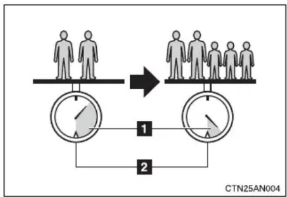
flowchart
graph TD
    A["Group 1: Two individuals"] --> B["Group 2: Three individuals"]
    B --> C["Step 1: Two circles with arrows indicating direction"]
    C --> D["Step 2: Two circles with arrows indicating direction"]
    D --> E["Final Step"]
    style A fill:#f9f,stroke:#333
    style B fill:#f9f,stroke:#333
    style C fill:#ccf,stroke:#333
    style D fill:#ccf,stroke:#333
    style E fill:#dfd,stroke:#333
1 Cargo capacity
2 Total load capacity (vehicle capacity weight) ( P. 482)
When 2 people with the combined weight of A lb. (kg) are riding in your vehicle, which has a total load capacity (vehicle capacity weight) of B lb. (kg), the available amount of cargo and luggage load capacity will be C lb. (kg) as follows:
B^2 lb. (kg) - A^1 lb. (kg) = C^*3 lb. (kg)
*1: A = Weight of people
^*2 : B = Total load capacity
*3: C = Available cargo and luggage load
In this condition, if 3 more passengers with the combined weight of D lb. (kg) get on, the available cargo and luggage load will be reduced E lb. (kg) as follows:
C lb. (kg) - D*4 lb. (kg) = E*5 lb. (kg)
*4: D = Additional weight of people
*5: E = Available cargo and luggage load
As shown in the example above, if the number of occupants increases, the cargo and luggage load will be reduced by an amount that equals the increased weight due to the additional occupants. In other words, if an increase in the number of occupants causes an excess of the total load capacity (combined weight of occupants plus cargo and luggage load), you must reduce the cargo and luggage on your vehicle.

CAUTION
■Things that must not be carried in the luggage compartment
The following things may cause a fire if loaded in the luggage compartment.
●Receptacles containing gasoline
Aerosol cans
■Storage precautions
Observe the following precautions.
Failure to do so may result in death or serious injury.
- Stow cargo and luggage in the luggage compartment whenever possible.
- Do not stack anything in the luggage compartment higher than the seatbacks.
Such items may be thrown about and possibly injure people in the vehicle in the event of sudden braking or in an accident.
- Do not place cargo or luggage in or on the following locations as the item may get under the brake or accelerator pedal and prevent the pedals from being depressed properly, block the driver's vision, or hit the driver or passengers, causing an accident:
- At the feet of the driver
- On the front passenger or rear seats (when stacking items)
- On the instrument panel
- On the dashboard

CAUTION
- Secure all items in the occupant compartment, as they may shift and injure someone during sudden braking, sudden swerving or an accident.
- When you fold down the rear seats, long items should not be place directly behind the front seats.
● Never allow anyone to ride in the luggage compartment. It is not designed for passengers. They should ride in their seats with their seat belts properly fastened. Otherwise, they are much more likely to suffer death or serious bodily injury, in the event of sudden braking, sudden swerving or an accident.
■Capacity and distribution
- Do not exceed the maximum axle weight rating or the total vehicle weight rating.
● Even if the total load of occupant's weight and the cargo load is less than the total load capacity, do not apply the load unevenly.
Improper loading may cause deterioration of steering or braking control which may cause death or serious injury.
Vehicle load limits include total load capacity, seating capacity, towing capacity and cargo capacity.
■ Total load capacity (vehicle capacity weight): (→P. 482)
Total load capacity means the combined weight of occupants, cargo and luggage.
■ Seating capacity: 5 occupants (Front 2, Rear 3)
Seating capacity means the maximum number of occupants whose estimated average weight is 150 lb. (68 kg) per person.
■Towing capacity
Toyota does not recommend towing a trailer with your vehicle.
Cargo capacity
Cargo capacity may increase or decrease depending on the weight and the number of occupants.
■ Total load capacity and seating capacity
These details are also described on the tire and loading information label. ( P. 374)

CAUTION
■Overloading the vehicle
Do not overload the vehicle.
It may not only cause damage to the tires, but also degrade steering and braking ability, resulting in an accident.
Carry out the necessary preparations and inspections before driving the vehicle in winter. Always drive the vehicle in a manner appropriate to the prevailing weather conditions.
■Pre-winter preparations
- Use fluids that are appropriate to the prevailing outside temperatures.
- Motor coolant
- Heater coolant
- Traction battery coolant
- Washer fluid
● Have a service technician inspect the condition of the 12-volt battery.
●Have the vehicle fitted with four snow tires or purchase a set of tire chains for the front tires.
Ensure that all tires are the same size and brand, and that chains match the size of the tires.
■Before driving the vehicle
Perform the following according to the driving conditions:
- Do not try to forcibly open a window or move a wiper that is frozen. Pour warm water over the frozen area to melt the ice. Wipe away the water immediately to prevent it from freezing.
- Do not try to forcibly open the charging port cap if it is frozen. Melt the ice using a hair dryer, immediately and thoroughly wiping away any moisture.
● To ensure proper operation of the climate control system fan, remove any snow that has accumulated on the air inlet vents in front of the windshield. - Check for and remove any excess ice or snow that may have accumulated on the exterior lights, vehicle's roof, chassis, around the tires or on the brakes.
- Remove any snow or mud from the bottom of your shoes before getting in the vehicle.
■When driving the vehicle
Accelerate the vehicle slowly, keep a safe distance between you and the vehicle ahead, and drive at a reduced speed suitable to road conditions.
■When parking the vehicle
Park the vehicle and push the P position switch without setting the parking brake. The parking brake may freeze up, preventing it from being released. If necessary, block the wheels to prevent inadvertent sliding or creeping.
Selecting tire chains
Use the correct tire chain size when mounting the snow chains. Chain size is regulated for each tire size.
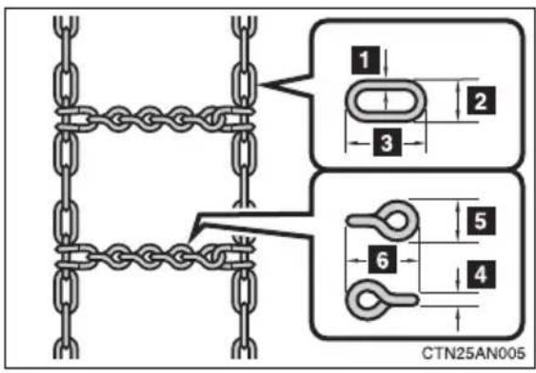
Side chain
1 0.12 in. (3 mm) in diameter
2 0.39 in. (10 mm) in width
3 1.18 in. (30 mm) in length
Cross chain
4 0.16 in. (4 mm) in diameter
5 0.55 in. (14 mm) in width
6 0.98 in. (25 mm) in length
Regulations on the use of tire chains
● Regulations regarding the use of tire chains vary depending on location and type of road. Always check local regulations before installing chains.
●Install the chains on the front tires.
■Tire chain installation
Observe the following precautions when installing and removing chains:
● Install and remove tire chains in a safe location.
● Install tire chains on the front tires only. Do not install tire chains on the rear tires.
● Install tire chains on front tires as tightly as possible. Retighten chains after driving 1/4 — 1/2 mile (0.5 — 1.0 km).
● Install tire chains following the instructions provided with the tire chains.

CAUTION
■Driving with snow tires
Observe the following precautions to reduce the risk of accidents.
Failure to do so may result in a loss of vehicle control and cause death or serious injury.
- Use tires of the size specified.
●Maintain the recommended level of air pressure. - Do not drive in excess of 75 mph (120 km/h), regardless of the type of snow tires being used.
●Use snow tires on all, not just some wheels. - Do not mix tires of different makes, models, tread patterns or treadwear.
■Driving with tire chains
Observe the following precautions to reduce the risk of accidents.
Failure to do so may result in the vehicle being unable to be driven safely, and may cause death or serious injury.
- Do not drive in excess of the speed limit specified for the tire chains being used, or 30 mph (50 km/h), whichever is lower.
● Avoid driving on bumpy road surfaces or over potholes.
● Avoid sudden acceleration, abrupt steering, sudden braking and shifting operations that cause sudden regenerative braking. - Slow down sufficiently before entering a curve to ensure that vehicle control is maintained.

NOTICE
■Repairing or replacing snow tires
Request repairs or replacement of snow tires from Toyota dealers or legitimate tire retailers.
This is because the removal and attachment of snow tires affects the operation of the tire pressure warning valves and transmitters.
■Fitting tire chains
The tire pressure warning valves and transmitters may not function correctly when tire chains are fitted.
2-5. Driving information
Trailer towing
Toyota does not recommend towing a trailer with your vehicle. Toyota also does not recommend the installation of a tow hitch or the use of a tow hitch carrier for a wheelchair, scooter, bicycle, etc. Your vehicle is not designed for trailer towing or for the use of tow hitch mounted carriers.
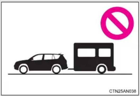
2-5. Driving information
Dinghy towing
Your vehicle is not designed to be dinghy towed (with 4 wheels on the ground) behind a motor home.
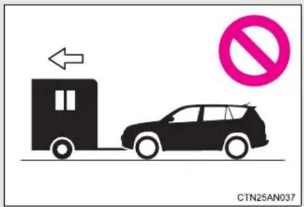

NOTICE
■To avoid serious damage to your vehicle
Do not tow your vehicle with the four wheels on the ground.
Interior features
3
3-1. Using the air conditioning system and defogger
Automatic air conditioning system ..... 276
Rear window and outside rear view mirror defoggers.... 292
3-2. Using the interior lights
Interior lights list...... 293
- Personal/interior light main switch.... 294
• Personal/interior lights 294
- Interior light 295
- Luggage compartment light 295
3-3. Using the storage features
List of storage features .... 296
- Glove box 297
- Console box.... 298
• Cup holders 299
- Bottle holders...... 300
• Auxiliary boxes...... 302
3-4. Other interior features
Sun visors 304
Vanity mirrors.... 305
Power outlets 306
Seat heaters.... 310
Armrest 313
Coat hooks.... 314
Assist grips.... 315
Floor mat.... 316
Luggage compartment features.... 317
Garage door opener...... 320
Safety Connect 326
The driving distance of the RAV4 EV is affected by the method of air conditioning use. In order to extend driving range, Toyota recommends using AUTO ECO mode and setting temperatures conservatively.
The effect on driving range can be confirmed on the meter. ( P. 218)
Operation mode
| Mode ECO setting Details | ||
| AUTO | ECO LO(Recommended) | Air conditioning is operated automatically, maintaining an optimal balance between cabin comfort and driving range. The seat heater is also linked and controlled depending on conditions. |
| ECO HI | Air conditioning is operated automatically. More importance is placed on extending driving range than in ECO LO mode and the air conditioning is used moderately. The seat heater is also linked and controlled depending on conditions. | |
| Normal | Air conditioning is operated automatically with more importance placed on cabin comfort than ECO LO mode. Therefore, driving range is shorter than when using ECO LO mode. | |
| Manual | ECO | Fan speed adjustment or changing air outlets is performed manually. Functions that have not been set in Manual mode will continue to operate in AUTO ECO mode. The seat heater is also linked and controlled depending on conditions. |
| Normal | Fan speed adjustment or changing air outlets is performed manually. | |
■Pre-climate (Remote Climate Control)
By setting the schedule, the air conditioning system can be turned on before getting in the vehicle. ( P. 53)
Even if the schedule has not been set, for users who own a smart phone, the air conditioning system can be turned on and off when away from the vehicle. ( P. 58)
Control panel

The operating section of the air conditioning panel uses capacitive touch sensors. ( P. 290)
Display
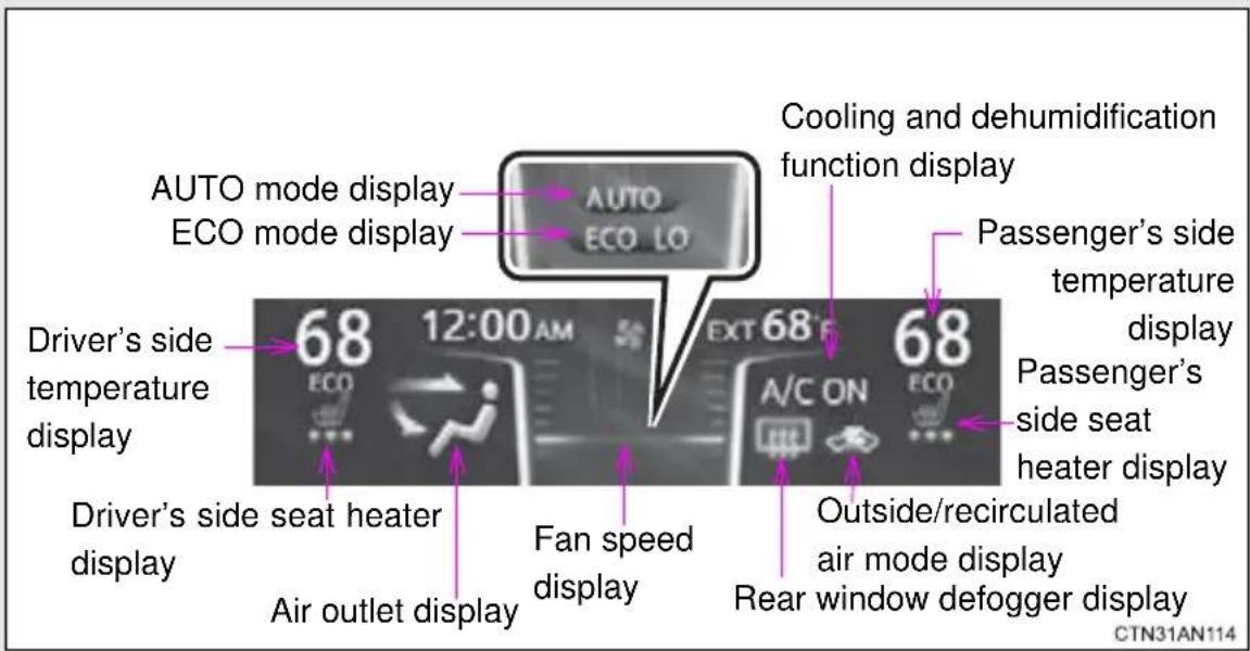
Using the AUTO ECO mode or AUTO mode
AUTO ECO mode
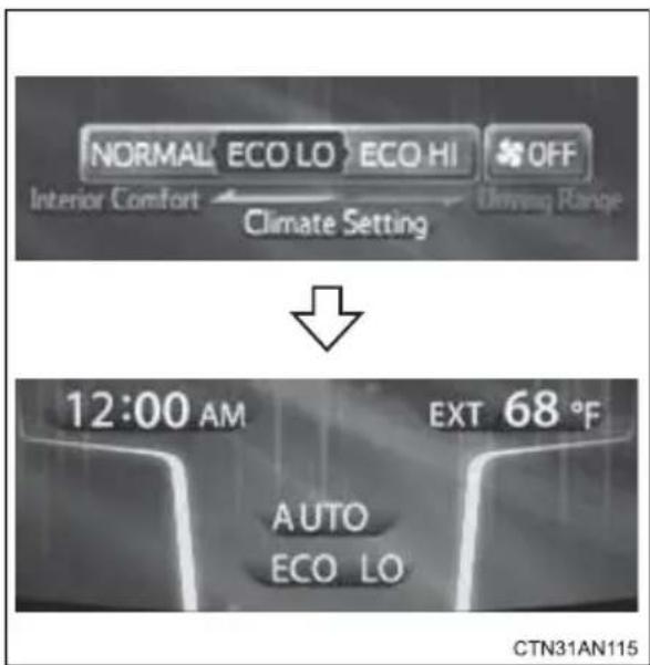
Touch

The air conditioning system begins to operate in AUTO ECO LO mode. Air outlets and fan speed are automatically adjusted according to the temperature setting.
In AUTO ECO mode, depending on the outside temperature and the set temperature, the seat heater operates, and the seat heater's temperature is automatically adjusted. (→P. 310)
When in AUTO mode, air conditioning operation status is not shown.
AUTO mode
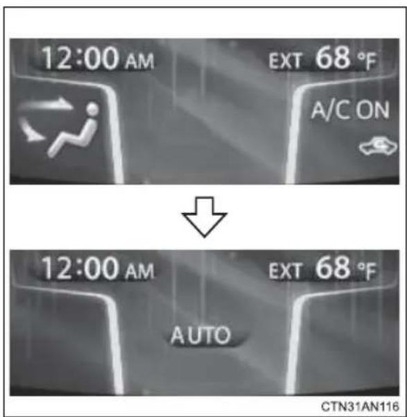
Touch AUTO .
The air conditioning system begins to operate. Air outlets and fan speed are automatically adjusted according to the temperature setting.
When in AUTO mode, air conditioning operation status is not shown.
■ Confirming AUTO mode operation status
When in AUTO mode, the operation status of fan speed, air outlet mode, outside/recirculated air mode and whether the A/C is on or off can be confirmed on the display by touching AUTO
The display will return to its previous state after a few seconds.
■Changing AUTO mode
Each time is touched, AUTO mode changes.
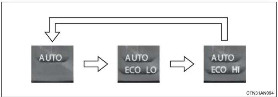
flowchart
graph TD
    A["AUTO"] --> B["AUTO ECO LO"]
    B --> C["AUTO ECO HI"]
Using the Manual ECO mode or Manual mode
If the following operations are performed while in AUTO ECO mode, the air conditioning system will change to Manual ECO mode. The system will also change to Manual mode if operations are performed when the system is off or in AUTO normal mode.
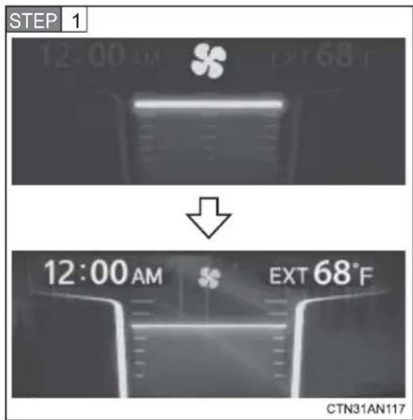
To adjust the fan speed, touch
speed and 📋 to decrease the fan speed.
To turn the fan off, press
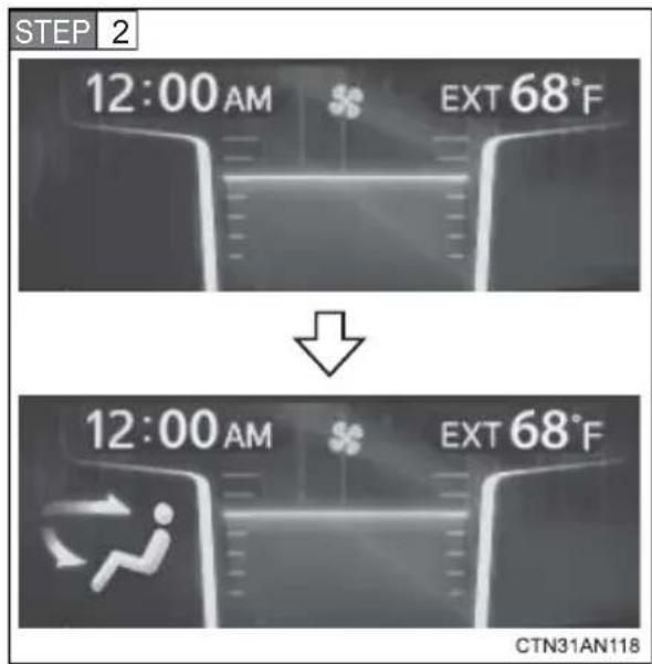
To change the air outlets, press
The air outlets used are switched each time the button is pressed. (→P. 283)
Changing the set temperature
Driver's side setting
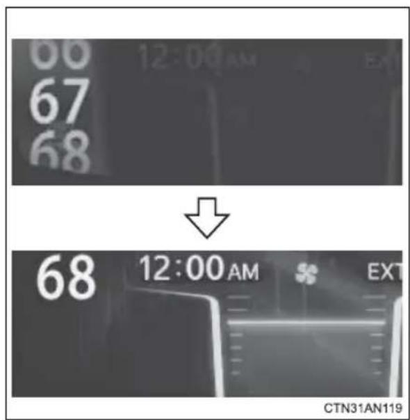
Touch on
on
to increase
the temperature and 🤨 to decrease the temperature.
Passenger's side setting
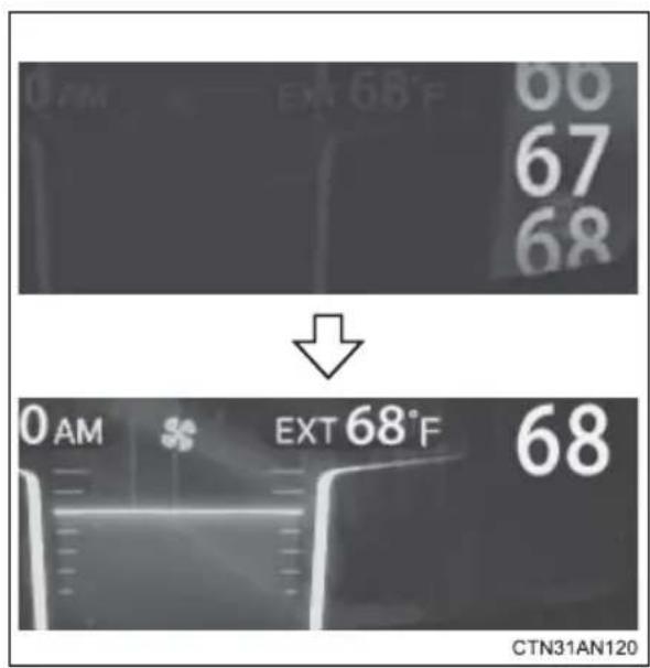
Touch on
on
to increase
the temperature and 🤨 to decrease the temperature.
■Passenger's side setting using "SYNC" mode
When "SYNC" mode is turned on, the passenger's side temperature will be linked to the driver's side temperature setting.
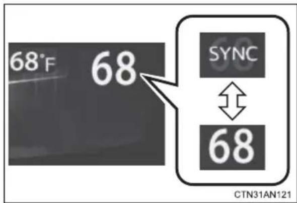
Touch

If "SYNC" mode is on, "SYNC" is shown on the passenger's side temperature display.
Each time SYNC is touched, "SYNC" mode changes between on/off.
Defogging the windshield
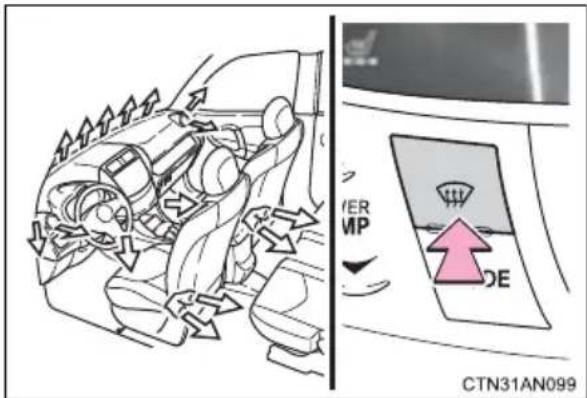
Press

The dehumidification function operates and fan speed increases.
Set the outside/recirculated air mode switch to outside air mode if the recirculated air mode is used. (It may switch automatically.)
To defog the windshield and the side windows early, turn the air flow and temperature up.
To return to the previous mode,
press again when the
windshield is defogged.
Air outlets and air flow
AUTO mode: The air outlets switch automatically according to conditions. The air flow mode can be confirmed by touching AUTO
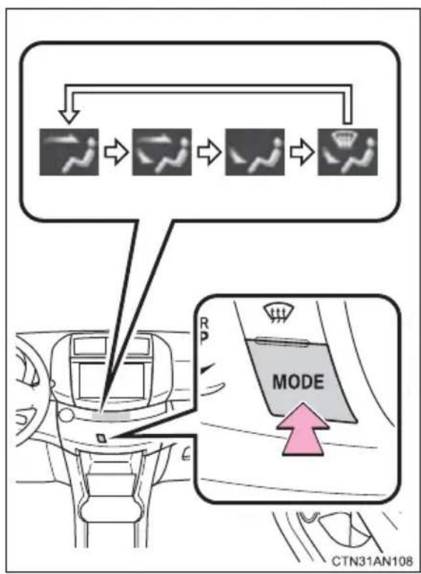
flowchart
graph TD
    A["Start"] --> B["Mode"]
    B --> C["Car with Position Indicator"]
    C --> D["Directional Mode"]
    D --> E["Car with Position Indicator"]
    E --> F["Mode"]
    F --> G["Car with Position Indicator"]
    G --> H["Mode"]
    H --> I["Car with Position Indicator"]
    I --> J["Mode"]
    J --> K["Car with Position Indicator"]
    K --> L["Mode"]
    L --> M["Car with Position Indicator"]
    M --> N["Mode"]
    N --> O["Car with Position Indicator"]
    O --> P["Mode"]
    P --> Q["Car with Position Indicator"]
    Q --> R["Mode"]
    R --> S["Car with Position Indicator"]
    S --> T["Mode"]
    T --> U["Car with Position Indicator"]
    U --> V["Mode"]
    V --> W["Car with Position Indicator"]
    W --> X["Mode"]
    X --> Y["Car with Position Indicator"]
Manual mode: The air outlets
switch each time
pressed.
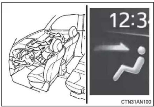
Air flows to the upper body.
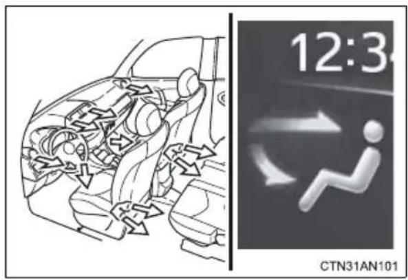
Air flows to the upper body and feet.
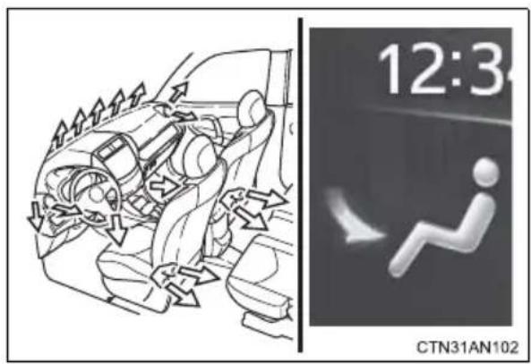
Air flows mainly to the feet.
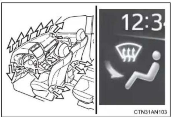
Air flows to the feet and the windshield defogger operates.
Adjusting the position of the air outlets
Center outlets
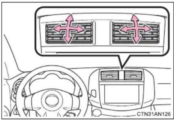
Direct air flow to the left or right, up or down.
Right and left side outlets
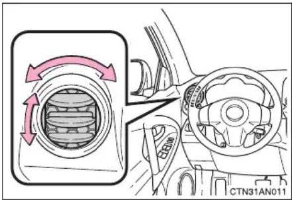
Direct air flow to the left or right, up or down.
Opening and closing the side outlets
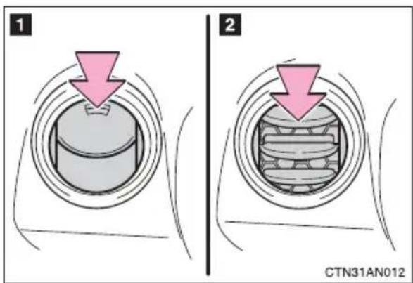
1 Open the vent.
2 Close the vent.
Switching between outside air and recirculated air modes
Touch

The mode switches between (recirculated air mode) and (outside air mode) each time is touched. (When is shown on the display, changing from to is not possible.)
■ Using automatic mode
Fan speed is adjusted automatically according to the temperature setting and the ambient conditions.
Therefore, the fan may stop for a while until warm or cool air is ready to flow after for is pressed.
■Fogging up of the windows
●The windows will easily fog up when the humidity in the vehicle is high. Turning 🐎 on will dehumidify the air from the outlets and defog the windshield effectively.
- If you turn off, the windows may fog up more easily.
●The windows may fog up if the (recirculated air mode) is used.
- When the outside air temperature is low, it may take a while for the condensation to clear from the windshield.
■Windshield fog detection function
When automatic mode is set, the humidity sensor ( P. 291) detects fog on the windshield and controls the air conditioning system to prevent fog.
■Outside/recirculated air mode
- When driving on dusty roads such as tunnels or in heavy traffic, set the outside/recirculated air mode button to the recirculated air mode. This is effective in preventing outside air from entering the vehicle interior. During cooling operation, setting the recirculated air mode will also cool the vehicle interior effectively.
●Outside/recirculated air mode may automatically switch depending on the temperature setting, the inside temperature, the outside temperature and humidity.
Also, outside air mode may be automatically switched to when the outside temperature is low.
■ When the outside temperature exceeds 75^ F ( 24^ C) and the air conditioning system is on
- In order to reduce the air conditioning power consumption, the air conditioning system may switch to recirculated air mode automatically. This may also reduce traction battery power consumption.
● Recirculated air mode is selected as a default mode when the "POWER" switch is turned to ON mode.
●It is possible to switch to outside air mode at any time by touching.
Air conditioning odors
● During use, various odors from inside and outside the vehicle may enter into and accumulate in the air conditioning system. This may then cause odor to be emitted from the vents.
●To reduce potential odors from occurring:
- It is recommended that the air conditioning system be set to outside air mode prior to turning the vehicle off.
- The start timing of the blower may be delayed for a short period of time after the air conditioning system is started in AUTO mode.
■ Air conditioning filter
→P. 381
Operation of the air conditioning system in AUTO ECO mode
In the AUTO ECO mode, the air conditioning system is controlled as follows to prioritize driving range:
● Compressor operation controlled to restrict heating/cooling capacity
●Fan speed restricted when automatic mode is selected
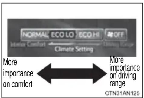
When it is desirable to set the cabin temperature to a more comfortable one, move the operating mode closer to "NORMAL" by pressing ECO. When it is desirable to increase driving range, move the selected mode closer to "OFF" by pressing ECO.
■The seat heater when using ECO LO or ECO HI mode
Depending on the outside temperature and the set temperature, the seat heater is automatically operated and its temperature adjusted. The seat heater can be adjusted to a desired temperature using the seat heater control. ( P. 310)
If the amount of charge remaining in the traction battery becomes low
Depending on the battery's condition, the air conditioning system's usage may be restricted or stopped (excluding the windshield defogger). If the air conditioning is restricted or turned off, one of the following messages will be shown on the HVAC display.
| Warning message Details | |
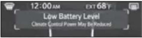 (Shown for a few seconds) (Shown for a few seconds) | Climate Control Power possibly limited.• The traction battery output is low.Any climate control setting can be selected. |
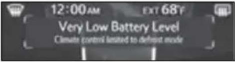 (Shown continually) (Shown continually) | Climate Control Power stopped.• The traction battery level is very low.• The traction battery output is very low.Only the windshield defogger and rear window defogger can be selected. |
 (Shown for a few seconds) (Shown for a few seconds) | Climate Control Power possibly limited.• The traction battery temperature is high.Some climate control setting cannot be selected. |
■Handling of the air conditioning panel
The operating section of the air conditioning panel uses capacitive touch sensors. In the following cases, incorrect operation or non-response may occur.
- If the operating section is dirty or has liquid attached to it, incorrect operation or non-response may occur.
- If the operating section receives electromagnetic waves, incorrect operation or non-response may occur.
- If wearing gloves during operation, non-response may occur.
- If fingernails are used to operate the system, non-response may occur.
- If a touch pen is used to operate the system, non-response may occur.
- If the palm of your hand touches the operating section during operation, incorrect operation may occur.
- If the palm of your hand touches the operating section, incorrect operation may occur.
- If operations are performed quickly, non-response may occur.
■Pre-climate operations
The pre-climate is automatically controlled by the set temperature at the time the “POWER” switch is turned off.
■Pre-climate operations automatic shut-off
→P.82
■While pre-climate is operating
→P.82

CAUTION
■To prevent the windshield from fogging up
Do not use during cool air operation in extremely humid weather.
The difference between the temperature of the outside air and that of the windshield can cause the outer surface of the windshield to fog up, blocking your vision.

NOTICE
■To prevent 12-volt battery discharge
Do not leave the air conditioning system on longer than necessary when the "POWER" switch is in ON mode.
Humidity sensor
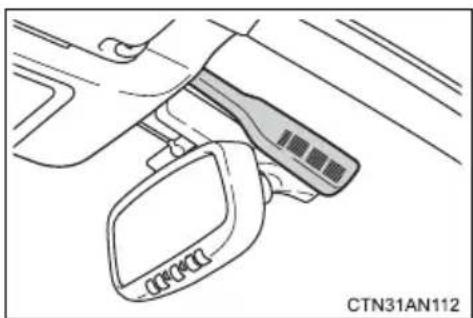
natural_image
Line drawing of a car interior showing a door clip and handle (no text or symbols)In order to detect fog on the windshield, a sensor which monitors the temperature of the windshield, the surrounding humidity, etc. is installed. ( P. 286)
Follow these points to avoid damaging the sensor:
- Do not disassemble the sensor
- Do not spray glass cleaner on the sensor or subject it to strong impacts
- Do not stick anything on the sensor
3-1. Using the air conditioning system and defogger Rear window and outside rear view mirror defoggers
The rear window defogger is used to defog the rear window. The outside rear view mirror defoggers are used to remove frost, dew or raindrops from the outside rear view mirrors.
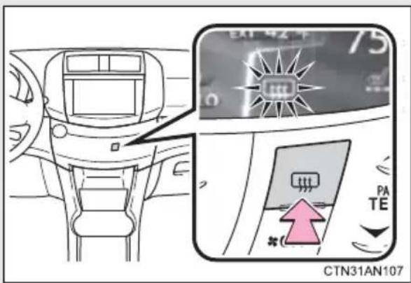
On/off
The defoggers will automatically turn off after approximately 15 minutes.
■The defogger can be operated when
The "POWER" switch is in ON mode.
■ Outside rear view mirror defoggers
Turning the rear window defogger on will turn the outside rear view mirror defoggers on.

CAUTION
■Outside rear view mirror defoggers
The surfaces of the outside rear view mirrors become hot. Do not touch them to prevent from burning yourself.
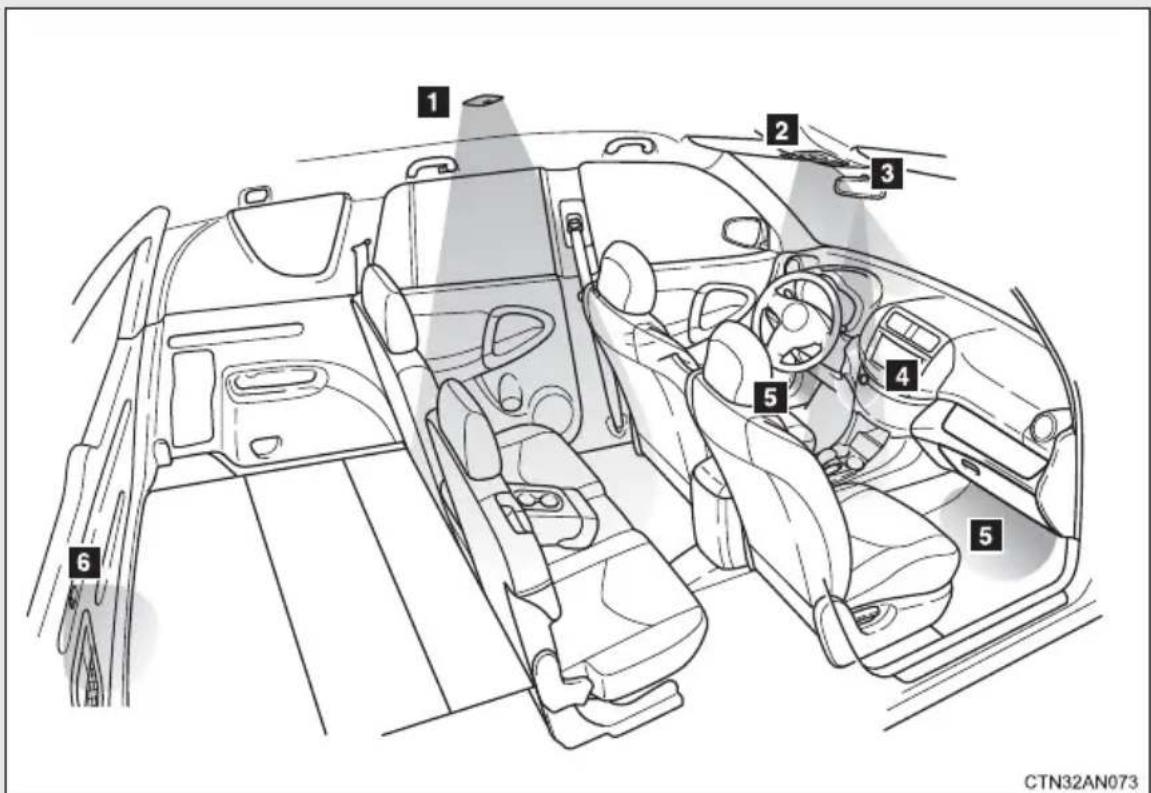
1 Interior light ( P. 295)
2 Personal/interior lights ( P. 294)
3 Shift lever light (when the "POWER" switch is in ON mode)
4 "POWER" switch light
5 Footwell lights (turns on/off according to whether the door is opened/closed)
6 Luggage compartment light (turns on/off according to whether the back door is opened/closed)
Personal/interior light main switch
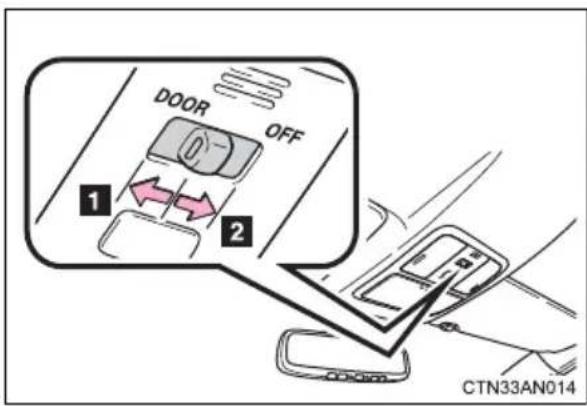
1 Door position
The personal lights and interior light come on when a door is opened. They go off when the doors are closed.
2 Off
The personal lights and interior light can be individually turned on or off.
Personal/interior lights
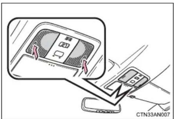
On/off
Interior light
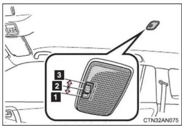
1 Door position
2 Off
3 On
Luggage compartment light
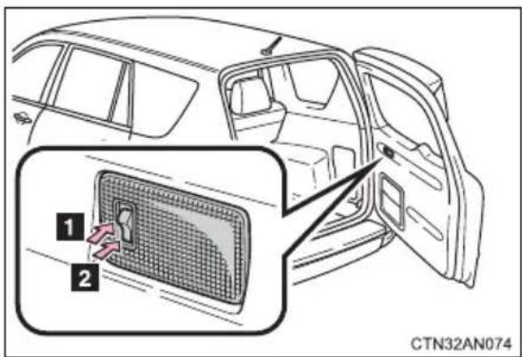
1 On
2 Off
■Illuminated entry system
The lights automatically turn on/off according to "POWER" switch mode, the presence of the electronic key, whether the doors are locked/unlocked, and whether the doors are open/closed.
■ To prevent 12-volt battery discharge (excluding luggage compartment light)
If the lights remain on when a door is not fully closed and the personal/interior light main switch is in door position, the lights will go off automatically after 20 minutes.
■ Customization that can be configured at Toyota dealer
Settings (e.g. the time elapsed before lights turn off) can be changed. (Customizable features → P. 500)
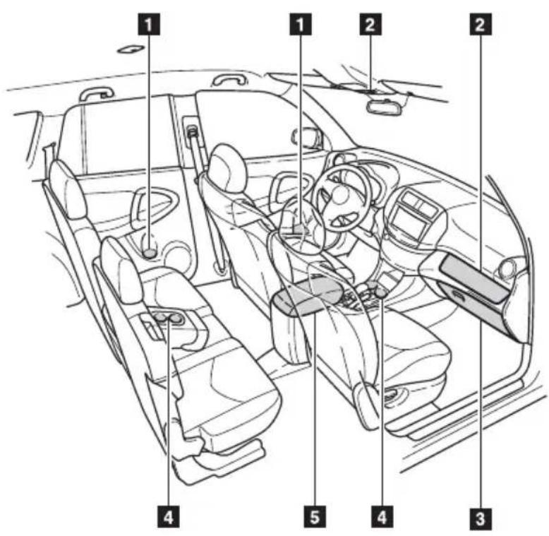
CTN33AN011
1 Bottle holders
2 Auxiliary boxes
3 Glove box
4 Cup holders
5 Console box

CAUTION
■Items that should not be left in the storage spaces
Do not leave glasses, lighters or spray cans in the storage spaces, as this may cause the following when cabin temperature becomes high:
●Glasses may be deformed by heat or cracked if they come into contact with other stored items.
●Lighters or spray cans may explode. If they come into contact with other stored items, the lighter may catch fire or the spray can may release gas, causing a fire hazard.
Glove box
The glove box can be opened by pulling the lever and locked and unlocked using the mechanical key.
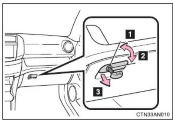
1 Unlock
2 Lock
3 Open

CAUTION
■Caution while driving
Keep the glove box closed. In the event of sudden braking or sudden swerving, an accident may occur due to an occupant being struck by the open glove box or the items stored inside.
Console box
Upper tray
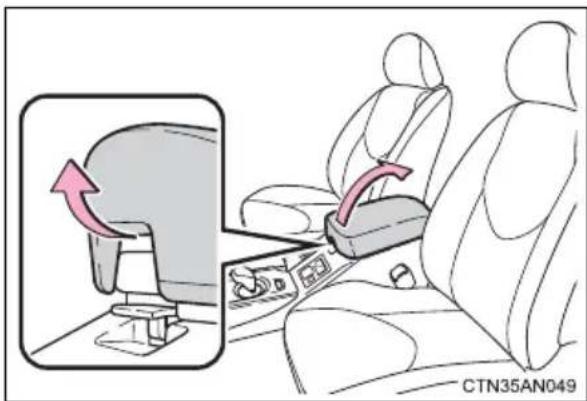
Lift the lid.
Lower box
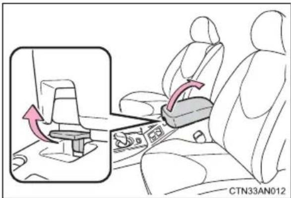
Pull the lever up and lift the lid.

CAUTION
■Caution while driving
Keep the console box closed. In the event of sudden braking, an accident may occur due to an occupant being struck by the open console box or the items stored inside.
Cup holders
Type A
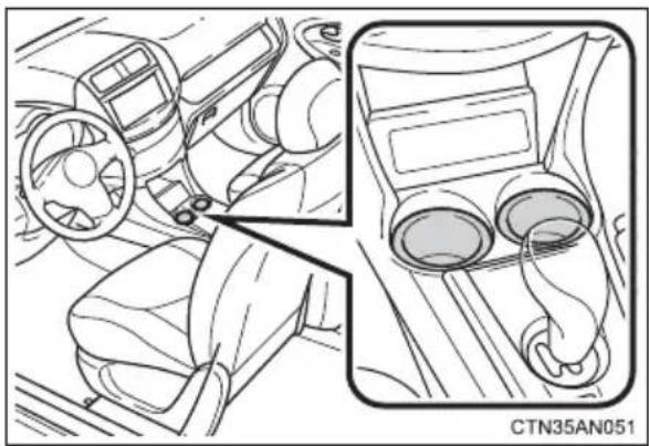
natural_image
Interior view of a car dashboard and steering wheel (no text or symbols visible)Type B
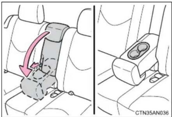
To use the cup holders, pull the strap forward and fold down the center seatback.
■Adjusting size of the cup holders (type A only)
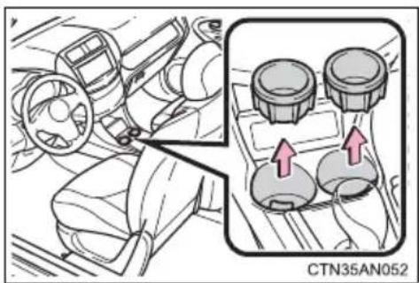
natural_image
Interior view of a car dashboard with steering wheel and control panel (no text or symbols visible)Remove the adapters.

CAUTION
■Items unsuitable for the cup holder
Do not place anything other than cups or beverage cans in the cup holders. Other items may be thrown out of the holders in the event of an accident or sudden braking, causing injury. If possible, cover hot drinks to prevent burns.
Bottle holders
Front seat
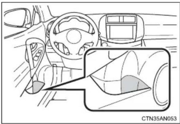
natural_image
Interior view of a car showing steering wheel, dashboard, and camera lens (no text or symbols)Rear seat
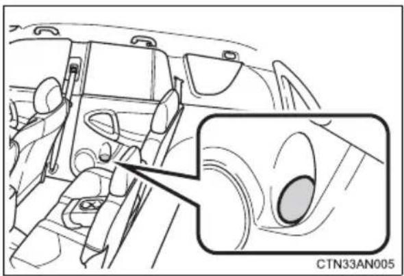
natural_image
Interior view of a car showing dashboard and engine compartment with a close-up inset (no text or symbols)
CAUTION
■Items unsuitable for the bottle holder
Do not place anything other than a bottle in the bottle holders.
Other items may be thrown out of the holders in the event of an accident or sudden braking and cause injury.

NOTICE
Items that should not be stowed in the bottle holders
Put the cap on before stowing a bottle. Do not place open bottles in the bottle holders, or glasses and paper cups containing liquid. The contents may spill and glasses may break.
Auxiliary boxes
Type A
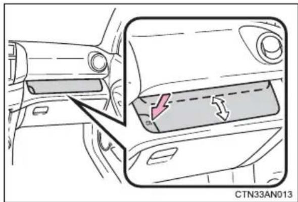
natural_image
Diagram of a car interior showing dashboard and side panel with directional arrows (no text or symbols)To open and close the auxiliary box, press the button.
Type B
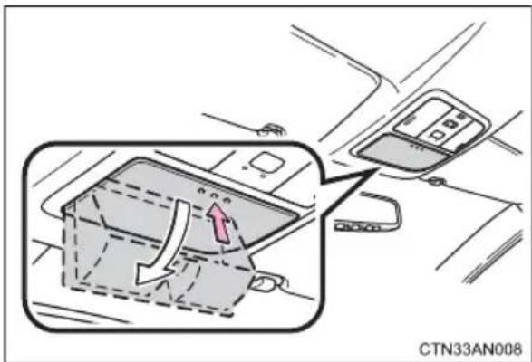
Press the lid.

CAUTION
■Caution while driving
Keep the auxiliary boxes closed. In the event of sudden braking, an accident may occur due to an occupant being struck by an open auxiliary box or the items stored inside.
■Items unsuitable for storing (type B)
Do not store items heavier than 0.4 lb. (0.2 kg).
Doing so may cause the overhead console to open and the items inside may fall out, resulting in an accident.

NOTICE
■Operating the auxiliary box
If it is difficult to open or close the auxiliary box on a steep hill, move the vehicle to a level place. To avoid damage to the auxiliary box, do not apply excessive force to operate it.
3-4. Other interior features
Sun visors
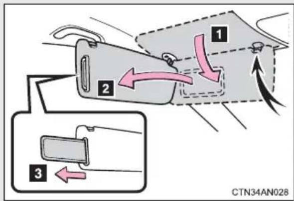
1 Forward position: Flip down.
2 Side position: Flip down, unhook, and swing to the side.
3 Side extender: Place in side position then slide backwards.
3-4. Other interior features
Vanity mirrors
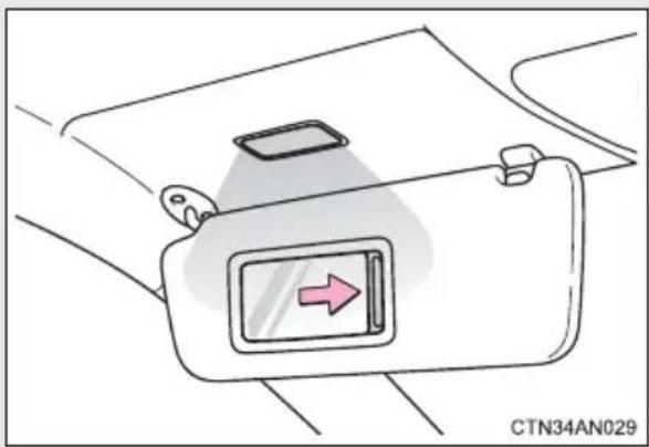
natural_image
Diagram of a car seatbelt with a directional arrow indicator (no text or symbols)Slide the cover to open.
The light turns on when the cover is opened.

NOTICE
■ To prevent 12-volt battery discharge
Do not leave the vanity lights on for extended periods while the EV system is off.
3-4. Other interior features
Power outlets
The power outlet can be used for 12 V accessories that run on less than 10 A.
Type A
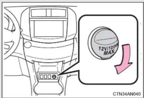
Type B
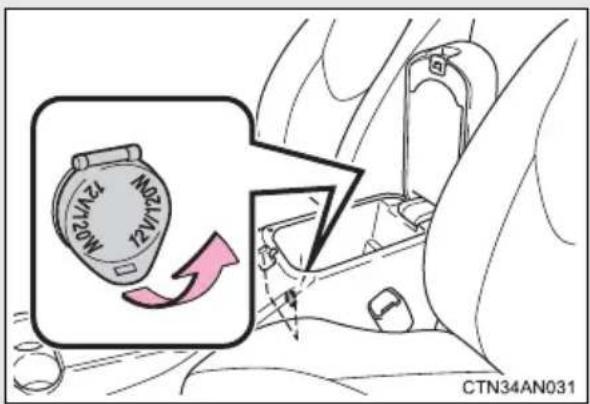
Type C
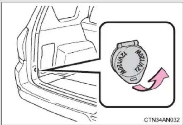
■The power outlet can be used when
The "POWER" switch is in ACCESSORY or ON mode.

CAUTION
■ Using a power outlet
Observe the following precautions to reduce the risk of injury.
- Use of the power outlet when it is wet with water or snow may result in electrical shocks and is extremely dangerous. The power outlet must be thoroughly dried before use.
- Do not allow children to use or play with the power outlet.
● Be careful not to get any part of your body caught in the power outlet lid. - When using electrical appliances, strictly follow any cautions and notices written on their labels and in the manufacturers' instruction manuals.
- Do not modify, disassemble or repair the power outlet in any way. Doing so may result in unexpected malfunctions or accidents, which could cause serious damage or injuries. Contact your Toyota dealer for any necessary repairs.
■ To prevent injuries and accidents, securely fix all electric appliances before use and do not use any appliances that may do any of the following:
●Distract the driver while driving, or hamper safe driving.
●Result in a fire or burn injuries due to the appliance rolling, falling or overheating while driving.
- Emit steam while the windows of the cabin are closed.

CAUTION
■ To prevent unexpected accidents, such as electric shocks, do not perform any of the following:
● Using the power outlet for electric heaters while sleeping.
●Contaminating the power outlet with liquid substances or mud.
●Handling electrical appliance plugs at the power outlet with wet hands or feet.
- Inserting foreign objects into the power outlet.
● Using malfunctioning electric appliances.
- Inserting inappropriate or badly fitting plugs into the power outlet.

NOTICE
■To avoid damaging the power outlet and the plug
- Close the power outlet lid when not in use.
- Do not allow foreign objects or liquids to enter the power outlet, as this may cause a short circuit.
- Do not use plug adaptors to connect too many plugs to the power outlet.
● After removing a plug, gently close the power outlet lid.
■To prevent blown fuse
Do not use an accessory that uses more than 12 V 10 A.
■To prevent 12-volt battery discharge
Do not use the power outlet longer than necessary when the EV system is off.

NOTICE
■To prevent any damage caused by heat
- Do not use any electrical appliances that give off intense heat, such as toasters.
- Do not use any electrical appliances that are easily affected by vibration or heat inside the vehicle. Vibration while driving, or the heat of the sun while parking, may result in damage to those electrical appliances.
If any electrical appliances are to be used while driving
Securely fasten both the appliances and their cables to prevent them from falling or getting caught in any of the power train components.
If the power outlet is loose when an electrical appliance plug is connected
Replace the outlet. Contact your Toyota dealer for any necessary replacements.
If the power outlet gets dirty
Use a soft, clean cloth to wipe it gently. Do not use any cleansing materials, such as organic solvents, wax, or compound cleaners, as these may damage the power outlet or cause it to malfunction.
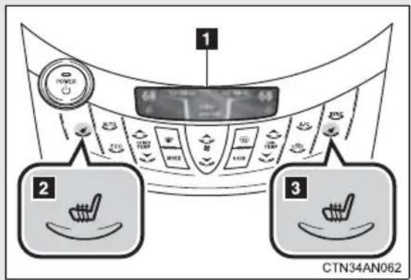
1 Display
2 Seat heater control (driver's seat)
3 Seat heater control (front passenger seat)
■Linked to air conditioning operations
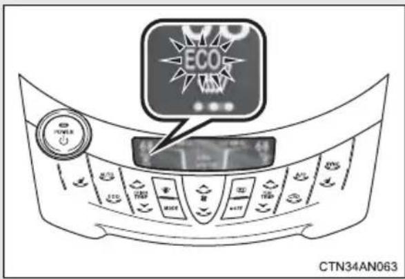
When the air conditioning is set to ECO LO or ECO HI mode, the seat heater is automatically operated and its temperature automatically adjusted according to the outside temperature and air conditioning settings.
“ECO” is shown on the display.
■Manual Mode
Each time the seat heater control is touched, the seat heater's operation or temperature setting changes.
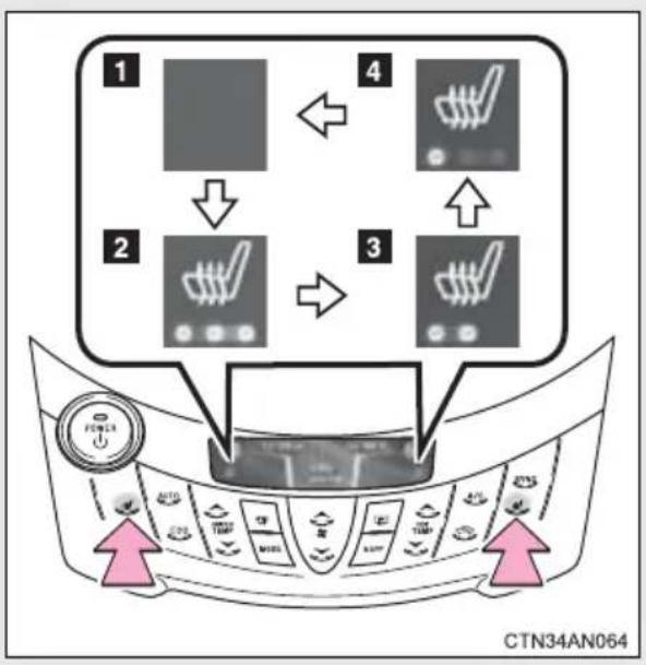
flowchart
graph TD
    A["1: Fan"] --> B["2: Battery"]
    B --> C["3: Switch"]
    C --> D["4: Battery"]
    D --> A
    style A fill:#f9f,stroke:#333
    style B fill:#ccf,stroke:#333
    style C fill:#cfc,stroke:#333
    style D fill:#fcc,stroke:#333
1 Seat heater off
2 High
3 Medium
4 Low
■The seat heaters can be used when
The "POWER" switch is in ON mode.
■When not in use
Turn the seat heater off.
■Front passenger seat heater
- When the air-conditioning is in ECO LO or ECO HI mode, the seat heater automatically turns on/off depending on whether the front passenger seat is occupied or not.
- When the seat heater is operating in manual mode, it does not automatically turn on/off depending on whether the front passenger seat is occupied or not.
- In order to prevent unintended seat heater operation, do not place luggage on the passenger seat.
The sensor may mistakenly judge the seat to be occupied and turn the seat heater on.

CAUTION
Burns
- Use caution when seating the following persons in a seat with the seat heater on to avoid the possibility of burns:
- Babies, small children, the elderly, the sick and the physically challenged
- Persons with sensitive skin
- Persons who are fatigued
- Persons who have taken alcohol or drugs that induce sleep (sleeping drugs, cold remedies, etc.)
- Do not cover the seat with anything when using the seat heater. Using the seat heater with a blanket or cushion increases the temperature of the seat and may lead to overheating.
- Do not use the seat heater more than necessary. Doing so may cause minor burns or overheating.

NOTICE
■To prevent seat heater damage
Do not put heavy objects that have an uneven surface on the seat and do not stick sharp objects (needles, nails, etc.) into the seat.
■To prevent 12-volt battery discharge
Turn the seat heaters off when the EV system is off.
3-4. Other interior features
Armrest
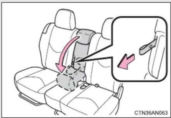
To use the armrest, pull the strap forward and fold down the center seatback.
To return the rear center seat-back to its original position, lift it up until it locks.

NOTICE
■To prevent damage to the armrest
Do not place too much strain on the armrest.
3-4. Other interior features
Coat hooks
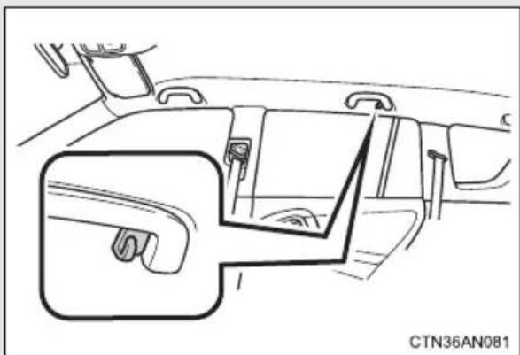
natural_image
Line drawing of a car interior showing the dashboard and seat area (no text or symbols)
CAUTION
■Items that must not be hung on the hook
Do not hang a coat hanger or other hard or sharp objects on the hook. If the SRS curtain shield airbags deploy, these items may become projectiles, causing death or serious injury.

NOTICE
■To prevent damage to the coat hook
Do not place too much load on the coat hook.
An assist grip installed on the ceiling can be used to support your body while sitting on the seat.
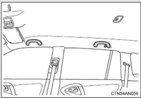
natural_image
Line drawing of a car interior showing dashboard, seatbelt, and rearview (no text or symbols)
CAUTION
■Assist grip
Do not use the assist grip when getting in or out of the vehicle or rising from your seat.

NOTICE
■To prevent damage to the assist grip
Do not hang any heavy object or put a heavy load on the assist grip.
Use only floor mats designed specifically for vehicles of the same model and model year as your vehicle. Fix them securely in place onto the carpet.
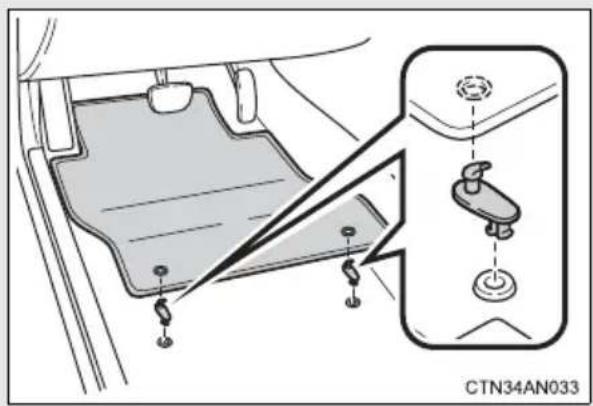
Fix the floor mat in place using the retaining hooks (clips) provided.
The shape of the retaining hooks (clips) and the fixing procedure of the floor mat for your vehicle may differ from those shown in the illustration. For details, refer to the floor mat retention clip installation instructions supplied with the clips.

CAUTION
Observe the following precautions.
Failure to do so may cause the driver's floor mat to slip, possibly interfering with the pedals while driving. An unexpectedly high speed may result or it may become difficult to stop the vehicle, leading to a serious accident.
■When installing the driver's floor mat
- Do not use floor mats designed for other models or different model year vehicles, even if they are Toyota Genuine floor mats.
●Only use floor mats designed for the driver's seat.
● Always install the floor mat securely using the retaining hooks (clips) provided. - Do not use two or more floor mats on top of each other.
- Do not place the floor mat bottom-side up or upside-down.
Before driving
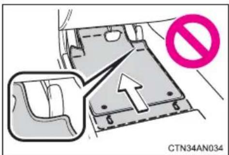
- Check that the floor mat is securely fixed in the correct place with all the provided retaining hooks (clips). Be especially careful to perform this check after cleaning the floor.
●With the EV system stopped and the shift position in P, fully depress each pedal to the floor to make sure it does not interfere with the floor mat.
3-4. Other interior features
Luggage compartment features
Cargo hooks
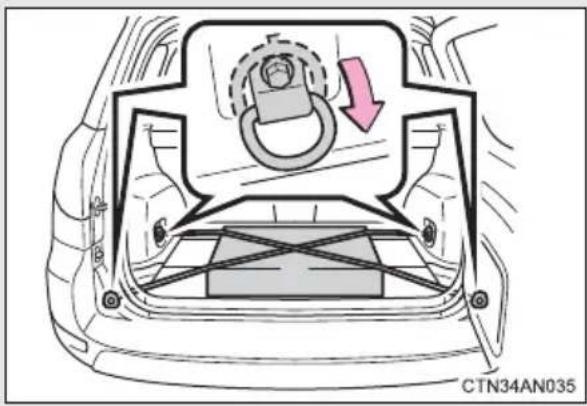
Pull the hook down to use it.
The cargo hooks are provided for securing loose items.
Grocery bag hooks
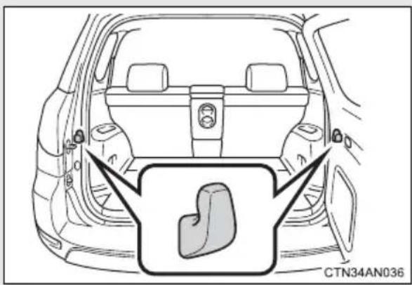
Storage box
Type A
The rear deck board can be folded up into two positions.
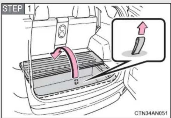
Lift the rear deck board.
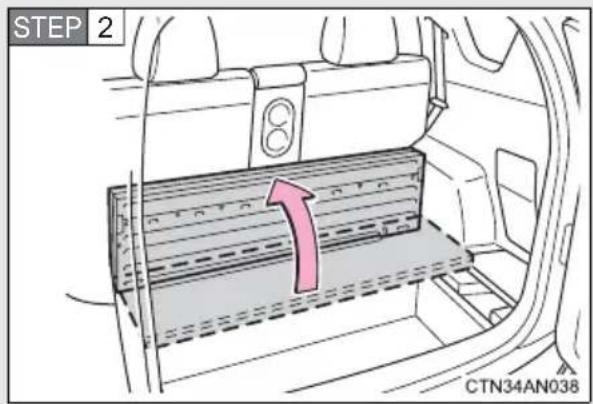
Type B
Fold up the deck board.
The deck board can be removed.
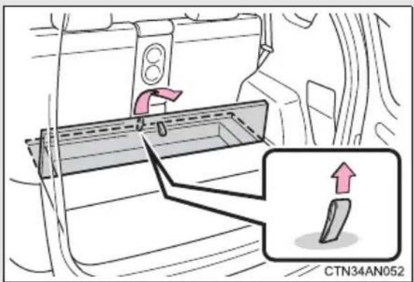
Lift the front deck board.

CAUTION
■When the cargo hooks are not in use
To avoid injury, always return the cargo hooks to their stowed positions.
■Caution while driving
Do not drive with any of the deck boards opened. Items may fall out and cause injury.

NOTICE
■To prevent damage to the grocery bag hooks
Do not hang heavy loads on the hooks.
■Space unsuitable for storing items
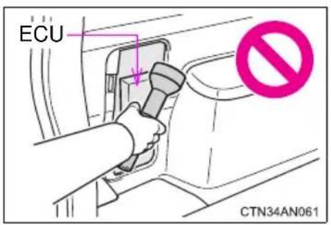
Do not put items in the space behind the cover on the left side of the luggage compartment.
The items may collide with the ECU while driving, damaging the unit.
3-4. Other interior features
Garage door opener
The garage door opener can be programmed to operate garage doors, gates, entry doors, door locks, home lighting systems, security systems, and other devices.
The garage door opener (HomeLink® Universal Transceiver) is manufactured under license from HomeLink®.
Programming HomeLink®
The HomeLink® compatible transceiver in your vehicle has 3 buttons which can be programmed to operate 3 different devices. Refer to the programming method below appropriate for the device.
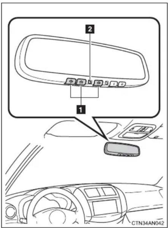
1 Buttons
2 Indicator
■Programming HomeLink®
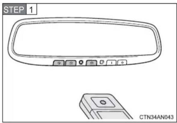
Point the remote control transmitter for the device 1 to 3 in. (25 to 75 mm) from the HomeLink® buttons.
Keep the HomeLink® indicator light in view while programming.
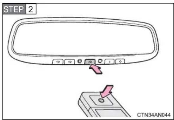
Press and hold one of the HomeLink® buttons and the transmitter button. When the HomeLink® indicator light changes from a slow to a rapid flash, you can release both buttons.
If the HomeLink® indicator light comes on but does not flash, or flashes rapidly for 2 seconds and remains lit, the HomeLink® button is already programmed. Use the other buttons or follow the "Reprogramming a HomeLink® button" instructions. (→P. 324)
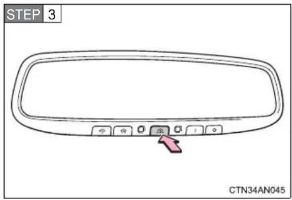
Test the HomeLink® operation by pressing the newly programmed button.
If a HomeLink® button has been programmed for a garage door, check to see if the garage door opens and closes. If the garage door does not operate, see if your remote control transmitter is of the rolling code type. Press and hold the programmed HomeLink® button. The remote control transmitter is of the rolling code type if the HomeLink® indicator light flashes rapidly for 2 seconds and then remains lit. If your transmitter is of the rolling code type, proceed to the heading "Programming a rolling code system".
STEP 4 Repeat the steps above to program another device for any of the remaining HomeLink® buttons.
■Programming a Rolling Code system
If your device is Rolling Code equipped, follow the steps under the heading “Programming HomeLink®” before proceeding with the steps listed below.
STEP 1 Locate the training button on the ceiling mounted garage door opener motor. The exact location and color of the button may vary by brand of garage door opener motor.
Refer to the operation manual supplied with the garage door opener motor for the location of the training button.
STEP 2 Press the training button.
Following this step, you have 30 seconds in which to initiate step 3 below.
STEP 3 Press and hold the vehicle's programmed HomeLink® button for 3 seconds and then release it. Repeat this step once again. The garage door may open.
If the garage door opens, the programming process is complete. If the door does not open, press and release the button a third time. This third press and release will complete the programming process by opening the garage door.
The ceiling mounted garage door opener motor should now recognize the HomeLink ^® signal and operate the garage door.
STEP 4 Repeat the steps above to program another rolling code system for any of the remaining HomeLink® buttons.
■Programming an entry gate
STEP 1 Place the remote control transmitter 1 to 3 in. (25 to 75 mm) away from the HomeLink® buttons.
Keep the HomeLink ^® indicator light in view while programming.
STEP 2 Press and hold the selected HomeLink® button.
STEP 3 Repeatedly press and release (cycle) the remote control transmitter for 2 seconds each until step 4 is completed.
STEP 4 When the HomeLink® indicator light starts to flash rapidly, release the buttons.
STEP 5 Test the HomeLink® operation by pressing the newly programmed button. Check to see if the gate/device operates correctly.
STEP 6 Repeat the steps above to program another device for any of the remaining HomeLink® buttons.
■Programming other devices
To program other devices such as home security systems, home door locks and lighting, contact your Toyota dealer for assistance.
■Reprogramming a button
The individual HomeLink ^® buttons cannot be erased but can be reprogrammed. To reprogram a button, follow the “Reprogramming a HomeLink ^® button” instructions.
Operating HomeLink®
Press the appropriate HomeLink® button. The HomeLink® indicator light should come on.
The HomeLink ^® compatible transceiver in your vehicle continues to send a signal for up to 20 seconds as long as the button is pressed.
Reprogramming a HomeLink® button
Press and hold the desired HomeLink® button. After 20 seconds, the HomeLink® indicator light will start flashing slowly. Keep pressing the HomeLink® button and press and hold the transmitter button until the HomeLink® indicator light changes from a slow to a rapid flash. Release the buttons.
Erasing the entire HomeLink ^® memory (all three programs)
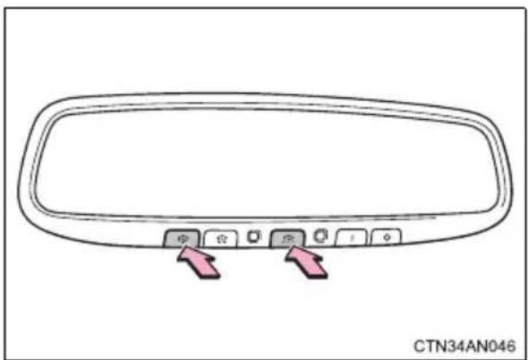
natural_image
Diagram of a car rearview mirror with two buttons and a small display (no text or symbols)Press and hold the 2 outside buttons for 10 seconds until the indicator light flashes.
If you sell your vehicle, be sure to erase the programs stored in the HomeLink® memory.
■Before programming
● Install a new battery in the remote control transmitter.
- The battery side of the remote control transmitter must be pointed away from the HomeLink® button.
■Certification for the garage door opener
FCC ID:NZLOBIHL4
NOTE:
This device complies with Part 15 of the FCC Rules.
Operation is subject to the following two conditions: (1) this device may not cause harmful interference, and (2) this device must accept any interference received, including interference that may cause undesired operation.
FCC WARNING:
Changes or modifications not expressly approved by the party responsible for compliance could void the user's authority to operate the equipment.
■When support is necessary
Visit on the web at www.homelink.com or call 1-800-355-3515.

CAUTION
■When programming a garage door or other remote control devices
The garage door or other devices may operate, so ensure people and objects are out of danger to prevent potential harm.
■Conforming to federal safety standards
Do not use the HomeLink ^® compatible transceiver with any garage door opener or device that lacks safety stop and reverse features as required by federal safety standards.
This includes any garage door that cannot detect an interfering object. A door or device without these features increases the risk of death or serious injury.
Safety Connect is a subscription-based telematics service that uses Global Positioning System (GPS) data and embedded cellular technology to provide safety and security features to subscribers. Safety Connect is supported by Toyota's designated response center, which operates 24 hours per day, 7 days per week.
Safety Connect service is available by subscription on select, telematics hardware-equipped vehicles.
By using the Safety Connect service, you are agreeing to be bound by the Telematics Subscription Service Agreement and its Terms and Conditions, as in effect and amended from time to time, a current copy of which is available at Toyota.com. All use of the Safety Connect service is subject to such then-applicable Terms and Conditions.
System components
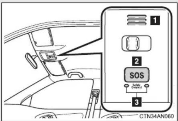
1 Microphone
2 "SOS" button
3 LED light indicators
Services
Subscribers have the following Safety Connect services available:
●Automatic Collision Notification*
Helps drivers receive necessary response from emergency service providers. ( P. 329)
*: U.S. Patent No. 7,508,298 B2
●Stolen Vehicle Location Helps drivers in the event of vehicle theft. (→P. 330)
●Emergency Assistance Button (SOS) Connects drivers to response-center support. (→P. 330)
●Enhanced Roadside Assistance Provides drivers various on-road assistance. (→P. 330)
Subscription
After you have signed the Telematics Subscription Service Agreement and are enrolled, you can begin receiving services. A variety of subscription terms is available for purchase. Contact your Toyota dealer, call 1-800-331-4331, or push the “SOS” button in your vehicle for further subscription details.
■Safety Connect Services Information
- Phone calls using the vehicles Bluetooth® technology will not be possible during Safety Connect.
●Safety Connect is available beginning Fall 2009 on select Toyota models. Contact with the Safety Connect response center is dependent upon the telematics device being in operative condition, cellular connection availability, and GPS satellite signal reception, which can limit the ability to reach the response center or receive emergency service support. Enrollment and Telematics Subscription Service Agreement required. A variety of subscription terms is available; charges vary by subscription term selected.
●Automatic Collision Notification, Emergency Assistance, Stolen Vehicle Location, and Enhanced Roadside Assistance will function in the United States, including Hawaii and Alaska, and in Canada. No Safety Connect services will function outside of the United States in countries other than Canada.
●Safety Connect services are not subject to section 255 of the Telecommunications Act and the device is not TTY compatible.
Languages
The Safety Connect response center will offer support in multiple languages. The Safety Connect system will offer voice prompts in English and Spanish. Please indicate your language of choice when enrolling.
■When contacting the response center
You may be unable to contact the response center if the network is busy.
Safety Connect LED light Indicators
When the “POWER” switch is turned to ON mode, the red indicator light comes on for 2 seconds then turns off. Afterward, the green indicator light comes on, indicating that the service is active.
The following indicator light patterns indicate specific system usage conditions:
●Green indicator light on = Active service
●Green indicator light flashing = Safety Connect call in process
● Red indicator light (except at vehicle start-up) = System malfunction (contact your Toyota dealer)
●No indicator light (off) = Safety Connect service not active
Safety Connect services
■Automatic Collision Notification
In case of either airbag deployment or severe rear-end collision, the system is designed to automatically call the response center. The responding agent receives the vehicle's location and attempts to speak with the vehicle occupants to assess the level of emergency. If the occupants are unable to communicate, the agent automatically treats the call as an emergency, contacts the nearest emergency services provider to describe the situation, and requests that assistance be sent to the location.
■Stolen Vehicle Location
If your vehicle is stolen, Safety Connect can work with local authorities to assist them in locating and recovering the vehicle. After filing a police report, call the Safety Connect response center at 1-800-331-4331 and follow the prompts for Safety Connect to initiate this service.
In addition to assisting law enforcement with recovery of a stolen vehicle, Safety-Connect-equipped vehicle location data may, under certain circumstances, be shared with third parties to locate your vehicle. Further information is available at Toyota.com.
Emergency Assistance Button ("SOS")
In the event of an emergency on the road, push the “SOS” button to reach the Safety Connect response center. The answering agent will determine your vehicle’s location, assess the emergency, and dispatch the necessary assistance required.
If you accidentally press the "SOS" button, tell the response-center agent that you are not experiencing an emergency.
■Enhanced Roadside Assistance
Enhanced Roadside Assistance adds GPS data to the already included warranty-based Toyota roadside service.
Subscribers can press the “SOS” button to reach a Safety Connect response-center agent, who can help with a wide range of needs, such as: towing, flat tire, etc. For a description of the Enhanced Roadside Assistance services and their limitations, please see the Safety Connect Terms and Conditions, which are available at Toyota.com.
Safety information for Safety Connect
Important! Read this information before using Safety Connect.
■Exposure to radio frequency signals
The Safety Connect system installed in your vehicle is a low-power radio transmitter and receiver. It receives and also sends out radio frequency (RF) signals.
In August 1996, the Federal Communications Commission (FCC) adopted RF exposure guidelines with safety levels for mobile wireless phones. Those guidelines are consistent with the safety standards previously set by the following U.S. and international standards bodies.
● ANSI (American National Standards Institute) C95.1 [1992]
●NCRP (National Council on Radiation Protection and Measurement) Report 86 [1986]
● ICNIRP (International Commission on Non-Ionizing Radiation Protection) [1996]
Those standards were based on comprehensive and periodic evaluations of the relevant scientific literature. Over 120 scientists, engineers, and physicians from universities, and government health agencies and industries reviewed the available body of research to develop the ANSI Standard (C95.1).
The design of Safety Connect complies with the FCC guidelines in addition to those standards.
■Certification for Safety Connect
FCC ID: O9EGTM1
NOTE:
This device complies with Part 15 of the FCC Rules. Operation is subject to the following two conditions: (1) This device may not cause harmful interference, and (2) this device must accept any interference received, including interference that may cause undesired operation.
FCC WARNING:
Changes or modifications not expressly approved by the party responsible for compliance could void the user's authority to operate the equipment.
Maintenance and care
4
4-1. Maintenance and care
Cleaning and protecting the vehicle exterior...... 334
Cleaning and protecting the vehicle interior...... 337
4-2. Maintenance
Maintenance requirements.... 340
General maintenance..... 342
4-3. Do-it-yourself maintenance
Do-it-yourself service precautions 346
Hood 349
Positioning a floor jack..... 351
Motor compartment...... 355
Tires.... 366
Tire inflation pressure ..... 374
Wheels 378
Air conditioning filter...... 381
Electronic key battery...... 383
Checking and replacing fuses 385
Headlight aim.... 398
Light bulbs 400
Perform the following to protect the vehicle and maintain it in prime condition:
- Working from top to bottom, liberally apply water to the vehicle body and wheel wells of the vehicle to remove any dirt and dust.
- Wash the vehicle body using a sponge or soft cloth, such as a chamois.
●For hard-to-remove marks, use car wash soap and rinse thoroughly with water.
●Wipe away any water.
●Wax the vehicle when the waterproof coating deteriorates.
If water does not bead on a clean surface, apply wax when the vehicle body is cool.
■Before washing the vehicle
Check that the charging port cap and charging port door on your vehicle are closed properly.
■Automatic car washes
- Fold the mirrors and remove the antenna before washing the vehicle. Start washing from the front of the vehicle. Make sure to re-install the antenna and extend the mirrors before driving.
- Brushes used in automatic car washes may scratch the vehicle surface and harm your vehicle's paint.
- In certain automatic car washes, the rear spoiler may interfere with machine operation. This may prevent the vehicle from being cleaned properly or result in damage to the rear spoiler.
■High pressure car washes
Do not allow the nozzles of the car wash to come within close proximity of the windows.
Aluminum wheels
- Remove any dirt immediately by using a neutral detergent. Do not use hard brushes or abrasive cleaners. Do not use strong or harsh chemical cleaners. Use the same mild detergent and wax as used on the paint.
- Do not use detergent on the wheels when they are hot, for example after driving for long distance in the hot weather.
●Wash detergent from the wheels immediately after use.
Bumpers
Do not scrub with abrasive cleaners.

CAUTION
■While charging
Do not wash the vehicle.
Doing so may cause the electrical components to malfunction or catch fire and also you may get an electric shock that may result in death or serious injury.
■When washing the vehicle
- Do not apply water to the inside of the motor compartment. Doing so may cause the electrical components etc. to malfunction or catch fire.
- Do not wash the underbody using a high-pressure washer. Doing so may cause the traction battery to malfunction or catch fire.

NOTICE
■ To prevent paint deterioration and corrosion on the body and components (aluminum wheels etc.)
●Wash the vehicle immediately in the following cases:
• After driving near the sea coast
• After driving on salted roads
- If coal tar or tree sap is present on the paint surface
- If dead insects, insect droppings or bird droppings are present on the paint surface
• After driving in an area contaminated with soot, oily smoke, mine dust, iron powder or chemical substances
- If the vehicle becomes heavily soiled with dust or mud
- If liquids such as benzene and gasoline are spilled on the paint surface
- If the paint is chipped or scratched, have it repaired immediately.
● To prevent the wheels from corroding, remove any dirt and store in a place with low humidity when storing the wheels.
■Cleaning the exterior lights
- Wash carefully. Do not use organic substances or scrub with a hard brush. This may damage the surfaces of the lights.
- Do not apply wax on the surfaces of the lights. Wax may cause damage to the lenses.
■Antenna installation and removal precautions
● Before driving, ensure that the antenna is installed.
- When the antenna is removed, such as before entering an automatic car wash, make sure to store it in a suitable place so as not to lose it. Also, before driving, make sure to reinstall the antenna in its original position.
■To prevent damage to the windshield wiper arms
When lifting the wiper arms away from the windshield, pull the driver side wiper arm upward first, and repeat for the passenger side. When returning the wipers to their original position, do so from the passenger side first.
The following procedures will help protect your vehicle's interior and keep it in top condition:
■Protecting the vehicle interior
Remove dirt and dust using a vacuum cleaner. Wipe dirty surfaces with a cloth dampened with lukewarm water.
■Cleaning the leather areas
- Remove dirt and dust using a vacuum cleaner.
●Wipe off any excess dirt and dust with a soft cloth dampened with diluted detergent.
Use a diluted water solution of approximately 5% neutral wool detergent.
●Wring out any excess water from the cloth and thoroughly wipe off all remaining traces of detergent.
- Wipe the surface with a dry, soft cloth to remove any remaining moisture. Allow the leather to dry in a shaded and ventilated area.
■Cleaning the synthetic leather areas
- Remove loose dirt using a vacuum cleaner.
- Apply a mild soap solution to the synthetic leather using a sponge or soft cloth.
- Allow the solution to soak in for a few minutes. Remove the dirt and wipe off the solution with a clean, damp cloth.
Caring for leather areas
Toyota recommends cleaning the interior of the vehicle at least twice a year to maintain the quality of the vehicle's interior.
■Shampooing the carpets
There are several commercial foaming-type cleaners available. Use a sponge or brush to apply the foam. Rub in overlapping circles. Do not use water. Wipe dirty surfaces and let them dry. Excellent results are obtained by keeping the carpet as dry as possible.
Seat belts
Clean with mild soap and lukewarm water using a cloth or sponge. Also check the belts periodically for excessive wear, fraying or cuts.

CAUTION
Water in the vehicle
- Do not splash or spill liquid in the vehicle, such as on the floor. Doing so may cause electrical components etc. to malfunction or catch fire.
- Do not get any of the SRS components or wiring in the vehicle interior wet. (→P. 155)
Electrical malfunction may cause the airbags to deploy or not function properly, resulting in death or severe injury.
■Cleaning the interior (especially instrument panel)
Do not use polish wax or polish cleaner. The instrument panel may reflect off the windshield, obstructing the driver's view and leading to an accident, resulting in death or serious injury.

NOTICE
■Cleaning detergents
- Do not use organic substances such as benzene or gasoline, acidic or alkaline solutions, dye, bleach or other detergent. Doing so may discolor the vehicle interior or cause streaks or damage to painted surfaces.
- Do not use polish wax or polish cleaner. The instrument panel's or other interior part's painted surface may be damaged.
■Preventing damage to leather surfaces
Observe the following precautions to avoid damage to and deterioration of leather surfaces:
- Remove any dust or dirt from leather surfaces immediately.
- Do not expose the vehicle to direct sunlight for extended periods of time. Park the vehicle in the shade, especially during summer.
- Do not place items made of vinyl, plastic, or containing wax on the upholstery, as they may stick to the leather surface if the vehicle interior heats up significantly.
Water on the floor
Do not wash the vehicle floor with water.
Vehicle systems such as the audio system may be damaged if water comes into contact with electrical components such as the audio system above or under the floor of the vehicle. Water may also cause the body to rust.
■Cleaning the inside of the rear window
- Do not use glass cleaner to clean the rear window, as this may cause damage to the rear window defogger heater wires or antenna. Use a cloth dampened with lukewarm water to gently wipe the window clean. Wipe the window in strokes running parallel to the heater wires or antenna.
- Be careful not to scratch or damage the heater wires or antenna.
To ensure safe and economical driving, day-to-day care and regular maintenance are essential. It is the owner's responsibility to perform regular checks. Toyota recommends the following maintenance:
■General maintenance
General maintenance should be performed on a daily basis. This can be done by yourself or by a Toyota dealer.
■Scheduled maintenance
Scheduled maintenance should be performed at specified intervals according to the maintenance schedule.
For details about maintenance items and schedules, refer to the "Scheduled Maintenance Guide" or "Owner's Manual Supplement".
■ Do-it-yourself maintenance
You can perform some maintenance procedures by yourself.
Please be aware that do-it-yourself maintenance may affect warranty coverage.
The use of Toyota Repair Manuals is recommended.
For details about warranty coverage, see the separate "Owner's Warranty Information Booklet" or "Owner's Manual Supplement".
■Repair and replacement
It is recommended that genuine Toyota parts be used for repairs to ensure performance of each system. If non-Toyota parts are used in replacement or if a repair shop other than a Toyota dealer performs repairs, confirm the warranty coverage.
- Allow inspection and repairs to be performed by a Toyota dealer
●Toyota technicians are well-trained specialists and are kept up to date with the latest service information. They are well informed about the operations of all systems on your vehicle.
- Keep a copy of the repair order. It proves that the maintenance that has been performed is under warranty coverage. If any problem should arise while your vehicle is under warranty, your Toyota dealer will promptly take care of it.

CAUTION
■If your vehicle is not properly maintained
Improper maintenance could result in serious damage to the vehicle and possible serious injury or death.
■Handling of the 12-volt battery
- Oils and fluids contained in vehicles as well as waste produced by component wear contain or emit chemicals known to the State of California to cause cancer and birth defects or other reproductive harm. Avoid exposure and wash any affected area immediately.
- 12-volt battery posts, terminals and related accessories contain lead and lead compounds which are known to cause brain damage. Wash your hands after handling. (→P. 362)
Listed below are the general maintenance items that should be performed at the intervals specified in the “Owner's Warranty Information Booklet” or “Owner's Manual Supplement/Scheduled Maintenance Guide”. It is recommended that any problem you notice should be brought to the attention of your Toyota dealer or qualified service shop for advice.
Motor compartment
| Items Check points | |
| 12-volt battery | Check the connections. (→P. 362) |
| Brake fluid | Is the brake fluid at the correct level? (→P. 361) |
| Motor/traction battery coolant | Is the coolant at the correct level? (→P. 357) |
| Heater coolant | Is the coolant at the correct level? (→P. 359) |
| Condenser/radiators | The condenser and radiators should be free from foreign objects. (→P. 360) |
| Washer fluid | Is there sufficient washer fluid? (→P. 365) |
Vehicle interior
| Items Check points | |
| Accelerator pedal | ·The accelerator pedal should move smoothly (without uneven pedal effort or catching). |
| Brake pedal | ·Does the brake pedal move smoothly? ·Does the brake pedal have appropriate clearance from the floor? (→P. 487) ·Does the brake pedal have the correct amount of free play? (→P. 487) |
| Brakes | ·The vehicle should not pull to one side when the brakes are applied. ·The brakes should work effectively. ·The brake pedal should not feel spongy. ·The brake pedal should not get too close to the floor when the brakes are applied. |
| Head restraints | ·Do the head restraints move smoothly and lock securely? |
| Transmission “Park” mechanism | ·When parked on a slope and the parking brake is on, is the vehicle securely stopped? |
| Indicators/buzzers | ·Do the indicators and buzzers function properly? |
| Lights | ·Do all the lights come on? ·Are the headlights aimed correctly? (→P. 398) |
| Parking brake | ·Does the parking brake lever move smoothly? ·When parked on a slope and the parking brake is on, is the vehicle securely stopped? |
| Seat belts | ·Do the seat belts operate smoothly? ·The seat belts should not be damaged. |
| Seats | ·Do the seat controls operate properly? |
| Steering wheel | ·Does the steering wheel rotate smoothly? ·Does the steering wheel have the correct amount of free play? ·There should not be any strange sounds coming from the steering wheel. |
Vehicle exterior
| Items Check points | |
| Doors • Do the doors operate smoothly? | |
| Hood | • Does the hood lock system work properly? |
| Fluid leaks | • There should not be any signs of fluid leakage after the vehicle has been parked. |
| Tires | • Is the tire inflation pressure correct?• The tires should not be damaged or excessively worn.• Have the tires been rotated according to the maintenance schedule?• The wheel nuts should not be loose. |
If you perform maintenance yourself, be sure to follow the correct procedures as given in these sections.
| Items Parts and tools | |
| 12-volt battery condition(→P. 362) | GreaseConventional wrench(for terminal clamp bolts) |
| Brake fluid level (→P. 361) | FMVSS No.116 DOT 3 or SAE J1703 brake fluidRag or paper towelFunnel (used only for adding brake fluid) |
| Motor coolant level (→P. 357) | “Zerex G 48” or “Glysantin G 48” onlyThe dilution ratio for both “Zerex G 48” and “Glysantin G 48” is 50% coolant and 50% deionized water.Funnel (used only for adding motor coolant) |
| Traction battery coolant level(→P. 357) | —(Contact your Toyota dealer if the level is on or below the “L” line.The reservoir cap is not intended to be opened by the user.Improper filling can lead to traction battery system damage. Only qualified personnel should service the traction battery coolant.) |
| Heater coolant level (→P. 359) | ·“Toyota Super Long Life Coolant” or similar high quality ethylene glycol based non-silicate, non-amine, non-nitrite and non-borate coolant with long-life hybrid organic acid technology “Toyota Super Long Life Coolant” is pre-mixed with 50% coolant and 50% deionized water. ·Funnel (used only for adding heater coolant) |
| Fuses (→P. 385) | ·Fuse with same amperage rating as original |
| Headlight aim (→P. 398) · Phillips-head screwdriver | |
| Light bulb (→P. 400) | ·Bulb with same number and watt-age rating as original ·Flathead screwdriver ·Phillips-head screwdriver |
| Condenser and radiators (→P. 360) | — |
| Tire inflation pressure (→P. 374) | ·Tire pressure gauge ·Compressed air source |
| Washer fluid (→P. 365) | ·Water or washer fluid containing antifreeze (for winter use) ·Funnel (used only for adding water or washer fluid) |

CAUTION
The motor compartment contains many mechanisms and fluids that may move suddenly, become hot, or become electrically energized. To avoid death or serious injury, observe the following precautions:
■When working on the motor compartment
● Make sure that the indicator on the “POWER” switch and the “READY” indicator are both off.
- Keep hands, clothing and tools away from the moving fans.
- Be careful not to touch the motor, power control unit, radiator, heater, etc. right after driving as they may be hot. Coolant and other fluids may also be hot.
- Do not leave anything that may burn easily, such as paper and rags, in the motor compartment.
- Do not smoke, cause sparks or expose an open flame to the 12-volt battery. 12-volt battery fumes are flammable.
- Be extremely cautious when working on the 12-volt battery. It contains poisonous and corrosive sulfuric acid.
● Take care because brake fluid can harm your hands or eyes and damage painted surfaces.
If fluid gets on your hands or in your eyes, flush the affected area with clean water immediately.
If you still experience discomfort, see a doctor.
●Never touch, disassemble, remove or replace the high voltage parts, cables and their connectors. It can cause severe burns or electric shock that may result in death or serious injury.
■ When working near the electric cooling fans or radiator grille
Be sure the "POWER" switch is off.
With the “POWER” switch in ON mode, the electric cooling fans may automatically start to run if the air conditioning is on and/or the coolant temperature is high. ( P. 360)
Safety glasses
Wear safety glasses to prevent flying or falling material, fluid spray, etc. from getting in the eyes.
Release the lock from the inside of the vehicle to open the hood.
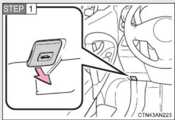
Pull the hood release lever. The hood will pop up slightly.
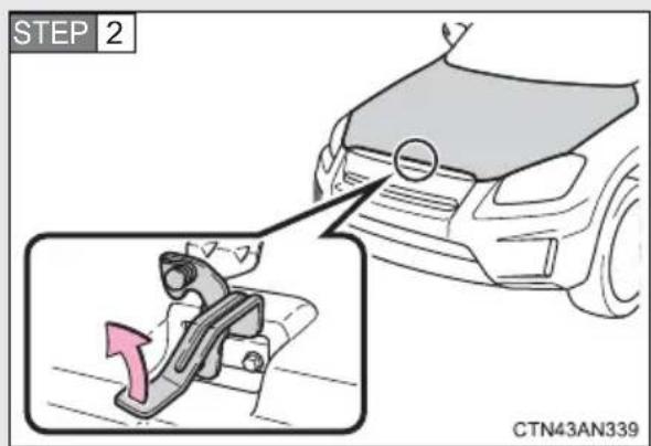
Lift the auxiliary catch lever and lift the hood.
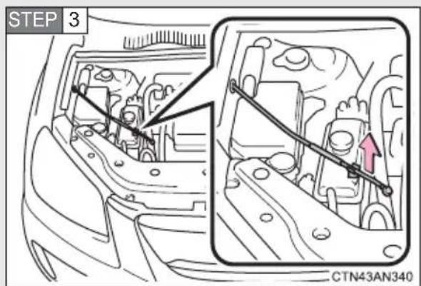
Lift up the supporting rod.
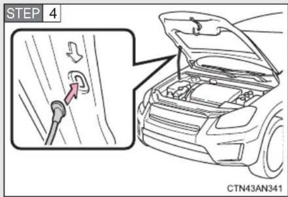
Hold the hood open by inserting the supporting rod into the slot.

CAUTION
■Pre-driving check
Check that the hood is fully closed and locked.
If the hood is not locked properly, it may open while the vehicle is in motion and cause an accident, which may result in death or serious injury.
■After installing the support rod into the slot
Make sure the rod supports the hood securely from falling down on to your head or body.

NOTICE
■When closing the hood
Be sure to return the support rod to its clip before closing the hood. Closing the hood with the support rod up could cause the hood to bend.
When raising your vehicle with a floor jack, position the jack correctly. Improper placement may damage your vehicle or cause injury.
■Positioning a floor jack
Front
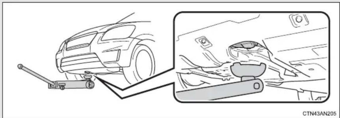
natural_image
Diagram showing a car suspension system with a lever and side view of the dashboard (no text or symbols)Rear
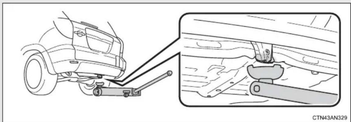
natural_image
Diagram showing a car's suspension system with a lever and lock mechanism, no text or symbols present■Positioning a Jack stand
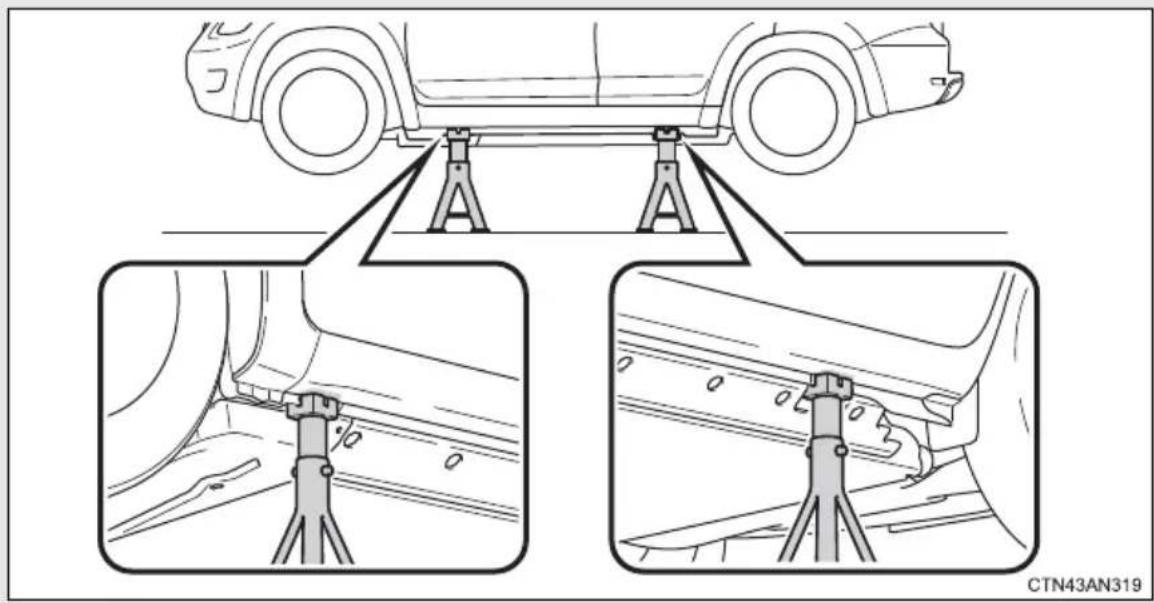
Using the jack stands
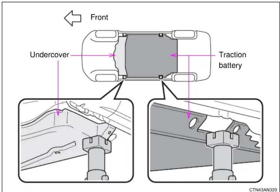
Before lowering the vehicle onto jack stands, check that the jack stands will not contact the traction battery or undercover.

CAUTION
■When raising your vehicle
Make sure to observe the following to reduce the possibility of death or serious injury.
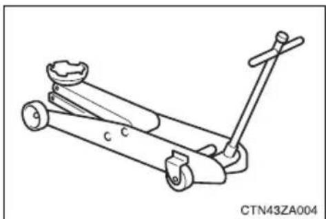
natural_image
Line drawing of a mechanical lever mechanism (no text or symbols)- Lift up the vehicle using a floor jack such as the one shown in the illustration.
- When using a floor jack, follow the instructions of the manual provided with the jack.
- Do not put any part of your body or get underneath the vehicle supported only by the floor jack.
● Always use floor jack and/or automotive jack stands on a solid, flat, level surface. - Do not start the EV system while the vehicle is supported by the floor jack.
- Stop the vehicle on level, firm ground, firmly set the parking brake and push the "P" position switch.
Make sure to set the floor jack properly at the jack point. Raising the vehicle with an improperly positioned floor jack will damage the vehicle and may cause the vehicle to fall off the floor jack. - Do not raise the vehicle while someone is in the vehicle.
- When raising the vehicle, do not place any objects on top of or underneath the floor jack.

CAUTION
■Tire jack usage
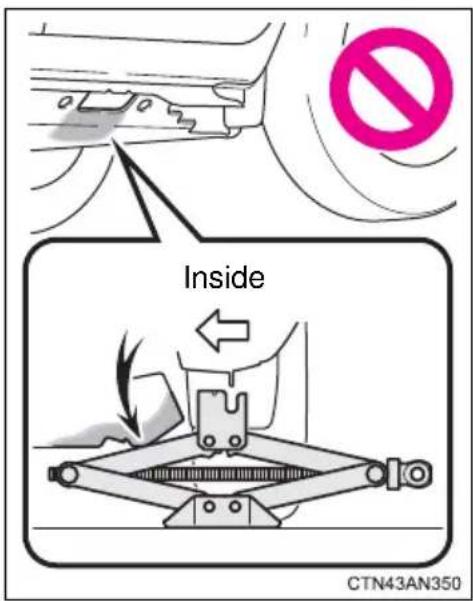
- Do not use a tire jack because its arms may interfere with the traction battery in the vehicle underbody.
●Forcibly using a tire jack may damage the traction battery or cause the vehicle to fall off the jack, resulting in death or serious injury.
■When using jack stands
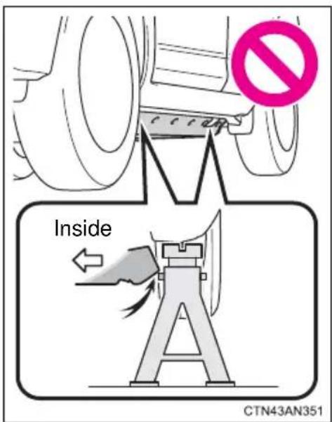
When lowering the vehicle onto jack stands, do not let the jack stands contact the traction battery or undercover. Doing so may damage the vehicle underbody. Working on the vehicle while a jack stand is contacting the traction battery is particularly dangerous because it may not only damage the traction battery, but the vehicle may fall, causing an accident that results in death or serious injury.
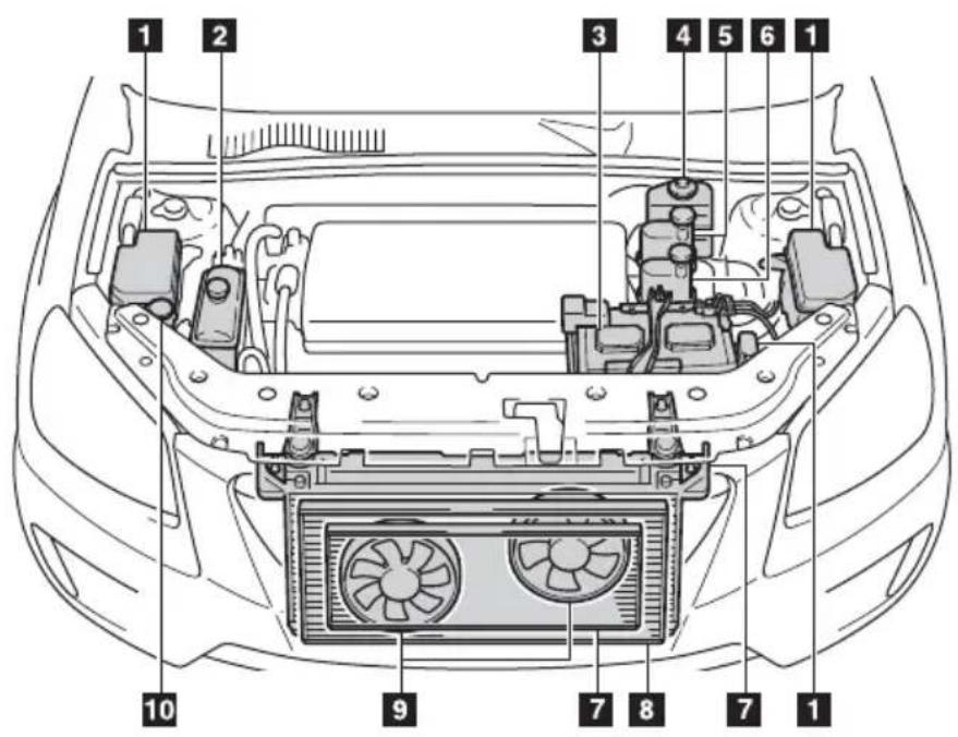
CTN43AN342
1 Fuse boxes ( P. 385)
2 Motor coolant reservoir
(→P. 357)
3 12-volt battery ( P. 362)
4 Brake fluid reservoir
(→P. 361)
5 Heater coolant reservoir
(→P. 359)
6 Traction battery coolant reservoir ( P. 357)
7 Radiators ( P. 360)
8 Condenser ( P. 360)
9 Electric cooling fans
10 Washer fluid tank ( P. 365)
Motor compartment cover
■Removing the motor compartment cover
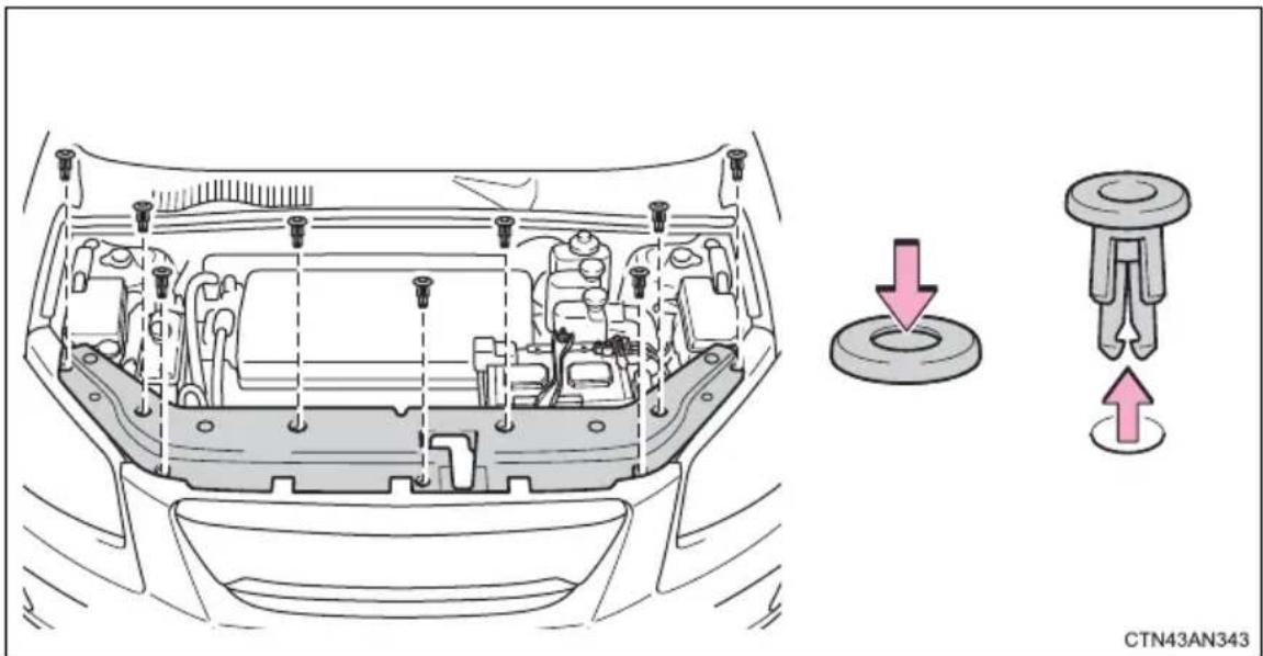
■Installing the clips
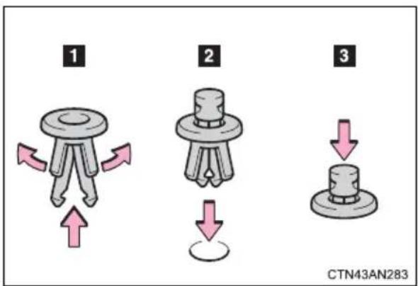

NOTICE
■After installing a motor compartment cover
Make sure that the cover is securely installed in its original position.
Motor/traction battery coolant
Motor coolant reservoir
The coolant level is satisfactory if it is between the "FULL" and "LOW" lines on the reservoir when the EV system is cold.
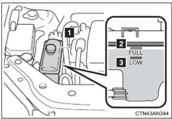
1 Reservoir cap
2 "FULL"
3 "LOW"
If the level is on or below the "LOW" line, add coolant up to the "FULL" line. (→P. 485)
Traction battery coolant reservoir
The coolant level is satisfactory if it is between the “F” and “L” lines on the reservoir when the EV system is cold.
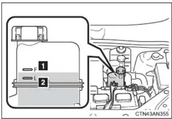
1 "F"
2 "L"
Contact your Toyota dealer if the level is on or below the "L" line. The reservoir cap is not intended to be opened by the user. Improper filling can lead to traction battery system damage. Only qualified personnel should service the traction battery coolant.
Coolant selection
Only use "Zerex G 48" or "Glysantin G 48".
"Zerex G 48" and "Glysantin G 48" are blue in color.
Reference:
The dilution ratio for both “Zerex G 48” and “Glysantin G 48” is 50% coolant and 50% deionized water. (Minimum temperature: approximately -32°F [-36°C])
For more details about motor/traction battery coolant, contact your Toyota dealer.
If the coolant level drops within a short time after replenishing
Visually check the radiator, hoses, motor/traction battery coolant reservoir cap, drain cock and water pump.
If you cannot find a leak, have your Toyota dealer test the cap and check for leaks in the cooling system.

CAUTION
■When the EV system is hot
Do not remove the coolant reservoir cap.
The cooling system may be under pressure and may spray hot coolant if the cap is removed, causing serious injuries, such as burns.

NOTICE
■When adding coolant
Coolant is neither plain water nor straight antifreeze. The correct mixture of water and antifreeze must be used to provide proper lubrication, corrosion protection and cooling. Be sure to read the antifreeze or coolant label.
- Do not add heater coolant to the motor coolant reservoir. Doing so will negatively affect the coolant's performance and cause the cooling system to malfunction.
If you spill coolant
Be sure to wash it off with water to prevent damage to parts or paint.
Heater coolant
The coolant level is satisfactory if it is between the "F" and "L" lines on the reservoir when the heater system is cold.
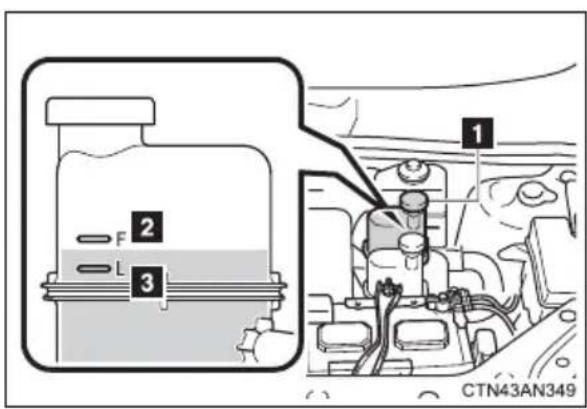
1 Reservoir cap
2 "F"
3 "L"
If the level is on or below the "L" line, add coolant up to the "F" line. (→P. 485)
Coolant selection
Only use "Toyota Super Long Life Coolant" or similar high quality ethylene glycol based non-silicate, non-amine, non-nitrite, and non-borate coolant with long-life hybrid organic acid technology.
"Toyota Super Long Life Coolant" is pink in color.
"Toyota Super Long Life Coolant" is a mixture of 50% coolant and 50% deionized water. (Minimum temperature: -31°F [-35°C])
For more details about heater coolant, contact your Toyota dealer.
If the coolant level drops within a short time after replenishing
Visually check the hoses, heater coolant reservoir cap, drain cock and water pump.
If you cannot find a leak, have your Toyota dealer test the cap and check for leaks in the heater system.

CAUTION
■When the heater is in use or just after use
Do not remove the coolant reservoir cap.
The heater system may be under pressure and may spray hot coolant if the cap is removed, causing serious injuries, such as burns.

NOTICE
■When adding heater coolant
Coolant is neither plain water nor straight antifreeze. The correct mixture of water and antifreeze must be used to provide proper lubrication and corrosion protection. Be sure to read the antifreeze or coolant label.
- Do not add motor coolant to the heater coolant reservoir. Doing so will negatively affect the coolant's performance and cause the heater system to malfunction.
If you spill coolant
Be sure to wash it off with water to prevent damage to parts or paint.
Condenser and radiators
Check the condenser and radiators, and clear away any foreign objects.
If either of the above parts are extremely dirty or you are not sure of their condition, have your vehicle checked by your Toyota dealer.

CAUTION
■When the EV system is hot
Do not touch the condenser or radiators as they may be hot and cause serious injuries, such as burns.
Brake fluid
- Checking fluid level
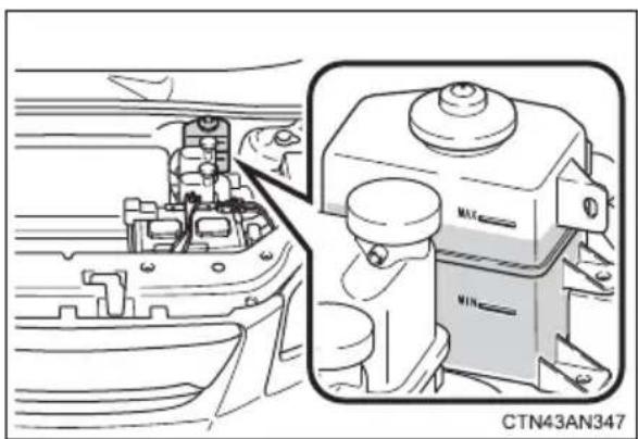
The brake fluid level should be between the "MAX" and "MIN" lines on the tank.
■ Adding fluid
Make sure to check the fluid type and prepare the necessary items.
| Fluid type SAE | J1703 or FMVSS No.116 DOT 3 brake fluid |
| Items Clean funnel | |
■Brake fluid can absorb moisture from the air
Excess moisture in the brake fluid can cause a dangerous loss of braking efficiency. Use only newly opened brake fluid.

CAUTION
■When filling the reservoir
Take care as brake fluid can harm your hands and eyes and damage painted surfaces.
If fluid gets on your hands or in your eyes, flush the affected area with clean water immediately.
If you still experience discomfort, see a doctor.

NOTICE
If the fluid level is low or high
It is normal for the brake fluid level to go down slightly as the brake pads wear or when the fluid level in the accumulator is high.
If the reservoir needs frequent refilling, there may be a serious problem.
12-volt battery
Check the 12-volt battery as follows:
■12-volt battery exterior
Make sure that the 12-volt battery terminals are not corroded and that there are no loose connections, cracks, or loose clamps.
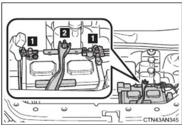
1 Terminals
2 Hold-down clamp
■Before recharging the 12-volt battery
When recharging, the 12-volt battery produces hydrogen gas which is flammable and explosive. Therefore, observe the following precautions before recharging:
- If recharging with the 12-volt battery installed on the vehicle, be sure to disconnect the ground cable.
● Make sure the power switch on the charger is off when connecting and disconnecting the charger cables to the 12-volt battery.
■After recharging/reconnecting the 12-volt battery
- Unlocking the doors using the smart key system may not be possible immediately after reconnecting the 12-volt battery. If this happens, use the wireless remote control or the mechanical key to lock/unlock the doors.
- Start the EV system with the “POWER” switch in ACCESSORY mode. The EV system may not start with the “POWER” switch turned off. However, the EV system will operate normally from the second attempt.
●The “POWER” switch mode is recorded by the vehicle. If the 12-volt battery is reconnected, the vehicle will return the “POWER” switch mode to the status it was in before the 12-volt battery was disconnected. Make sure to turn the “POWER” switch off before disconnecting the 12-volt battery. Take extra care when connecting the 12-volt battery if the “POWER” switch mode prior to discharge is unknown. - When the 12-volt battery is reconnected, start the EV system, depress the brake pedal, and confirm that it is possible to shift into each shift position.
If the system will not start even after multiple attempts, contact your Toyota dealer.

CAUTION
■Chemicals in the 12-volt battery
The 12-volt battery contains poisonous and corrosive sulfuric acid and may produce hydrogen gas which is flammable and explosive. To reduce the risk of death or serious injury, take the following precautions while working on or near the 12-volt battery:
- Do not cause sparks by touching the 12-volt battery terminals with tools.
●Do not smoke or light a match near the 12-volt battery.
● Avoid contact with eyes, skin and clothes.
● Never inhale or swallow electrolyte.
●Wear protective safety glasses when working near the 12-volt battery. - Keep children away from the 12-volt battery.

CAUTION
■Where to safely charge the 12-volt battery
Always charge the 12-volt battery in an open area. Do not charge the 12-volt battery in a garage or closed room where there is insufficient ventilation.
■How to recharge the 12-volt battery
Only perform a slow charge (5 A or less). The 12-volt battery may explode if charged at a quicker rate.
Emergency measures regarding electrolyte
● If electrolyte gets in your eyes
Flush your eyes with clean water for at least 15 minutes and get immediate medical attention. If possible, continue to apply water with a sponge or cloth while traveling to the nearest medical facility.
●If electrolyte gets on your skin
Wash the affected area thoroughly. If you feel pain or burning, get medical attention immediately.
● If electrolyte gets on your clothes
It can soak through clothing on to your skin. Immediately take off the clothing and follow the procedure above if necessary.
●If you accidentally swallow electrolyte
Drink a large quantity of water or milk. Get emergency medical attention immediately.

NOTICE
■When recharging the 12-volt battery
Never recharge the 12-volt battery while the EV system is operating. Also, be sure all accessories are turned off.
Washer fluid
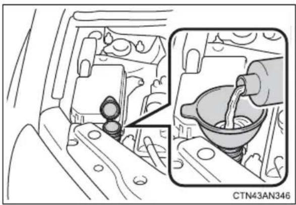
natural_image
Diagram showing engine compartment with internal components and a close-up of a mechanical component (no text or symbols)If any washer does not work or the warning message appears on the multi-information display, the washer tank may be empty. Add washer fluid.

CAUTION
■When adding washer fluid
Do not add washer fluid when the EV system is hot or operating as washer fluid contains alcohol and may catch fire if spilled on the motor etc.

NOTICE
■ Do not use any fluid other than washer fluid
Do not use soapy water or antifreeze instead of washer fluid. Doing so may cause streaking on the vehicle's painted surfaces.
Diluting washer fluid
Dilute washer fluid with water as necessary. Refer to the freezing temperatures listed on the label of the washer fluid bottle.
Replace or rotate tires in accordance with maintenance schedules and treadwear.
When replacing a tire or performing tire rotation, contact your Toyota dealer.
- Checking tires
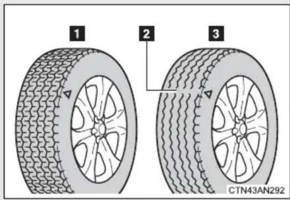
1 New tread
2 Treadwear indicator
3 Worn tread
The location of treadwear indicators is shown by the "TWI" or "△" marks, etc., molded on the sidewall of each tire.
Tire rotation
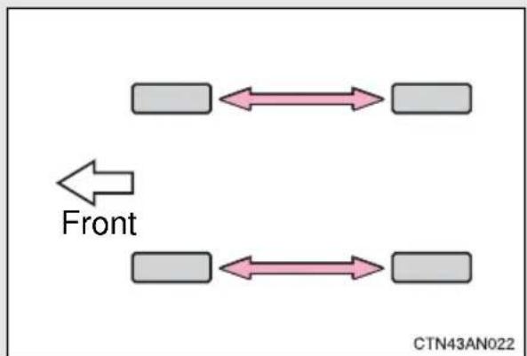
flowchart
graph LR
    A[" "] <--> B[" "]
    C[" "] <--> D[" "]
    E[" "] <--> F[" "]
    G[" "] <--> H[" "]
    I[" "] <--> J[" "]
    K[" "] <--> L[" "]
    M[" "] <--> N[" "]
    O[" "] <--> P[" "]
    Q[" "] <--> R[" "]
    S[" "] <--> T[" "]
    U[" "] <--> V[" "]
    W[" "] <--> X[" "]
    Y[" "] <--> Z[" "]
    AA[" "] <--> AB[" "]
    AC[" "] <--> AD[" "]
    AE[" "] <--> AF[" "]
    AG[" "] <--> AH[" "]
    AI[" "] <--> AJ[" "]
    AK[" "] <--> AL[" "]
    AM[" "] <--> AN[" "]
    AO[" "] <--> AP[" "]
    AQ[" "] <--> AR[" "]
    AS[" "] <--> AT[" "]
    AU[" "] <--> AV[" "]
    AW[" "] <--> AX[" "]
    AY[" "] <--> AZ[" "]
    BA[" "] <--> BB[" "]
    BC[" "] <--> BD[" "]
    BE[" "] <--> BF[" "]
    BG[" "] <--> BH[" "]
    BI[" "] <--> BJ[" "]
    BK[" "] <--> BL[" "]
    BM[" "] <--> BN[" "]
    BO[" "] <--> BP[" "]
    BP[" "] <--> BPB[" "]
    BPB[" "] <--> BPC[" "]
    BPC[" "] <--> BPD[" "]
    BPD[" "] <--> BPE[" "]
    BPE[" "] <--> BPF[" "]
    BPF[" "] <--> BPG[" "]
    BPG[" "] <--> BPH[" "]
    BPH[" "] <--> BPI[" "]
    BPI[" "] <--> BPJ[" "]
    BPJ[" "] <--> BPK[" "]
    BPK[" "] <--> BPL[" "]
    BPL[" "] <--> BPM[" "]
    BPM[" "] <--> BPN[" "]
    BPN[" "] <--> BPO[" "]
    BPO[" "] <--> BPP[" "]
    BPP[" "] <--> BPQ[" "]
    BPQ[" "] <--> BPR[" "]
    BPR[" "] <--> BPS[" "]
    BPS[" "] <--> BPT[" "]
    BPT[" "] <--> BPU[" "]
    BPU[" "] <--> BPV[" "]
    BPV[" "] <--> BPW[" "]
    BPW[" "] <--> BPX[" "]
    BPX[" "] <--> BPY[" "]
    BPY[" "] <--> BPZ[" "]
    BPZ[" "] <--> BPYB[" "]
    BPYB[" "]
Rotate the tires in the order shown.
To equalize tire wear and extend tire life, Toyota recommends that tire rotation is carried out at the same interval as tire inspection.
■The tire pressure warning system
Your Toyota is equipped with a tire pressure warning system that uses tire pressure warning valves and transmitters to detect low tire inflation pressure before serious problems arise. (→P. 419)
Installing tire pressure warning valves and transmitters
When replacing tires or wheels, tire pressure warning valves and transmitters must also be installed.
When new tire pressure warning valves and transmitters are installed, new tire pressure warning valve and transmitter ID codes must be registered in the tire pressure warning computer and the tire pressure warning system must be initialized. Have tire pressure warning valve and transmitter ID codes registered by your Toyota dealer. (→P. 367)
Registering ID codes
The tire pressure warning valve and transmitter is equipped with a unique ID code. When replacing a tire pressure warning valve and transmitter, it is necessary to register the ID code of tire pressure warning valve and transmitter. Have the ID code registered by your Toyota dealer.
■When to replace your vehicle's tires
Tires should be replaced if:
- You have tire damage such as cuts, splits, cracks deep enough to expose the fabric, or bulges indicating internal damage.
● A tire goes flat repeatedly or cannot be properly repaired due to the size or location of a cut or other damage.
If you are not sure, consult with your Toyota dealer.
■Replacing tires and wheels
If the ID code of the tire pressure warning valve and transmitter is not registered, the tire pressure warning system will not work properly. After driving for about 20 minutes, the tire pressure warning light blinks for 1 minute and stays on to indicate a system malfunction.
Tire life
Any tire over 6 years old must be checked by a qualified technician even if they have seldom or never been used or damage is not obvious.
■Routine tire inflation pressure checks
The tire pressure warning system does not replace routine tire inflation pressure checks. Make sure to check tire inflation pressure as part of your routine of daily vehicle checks.
■Maximum load of tire
Check that the number given by dividing the maximum load by 1.10 of the replacement tire is greater than 1/2 of the Gross Axle Weight Ratings (GAWR) of either the front axle or the rear axle, whichever is greater.
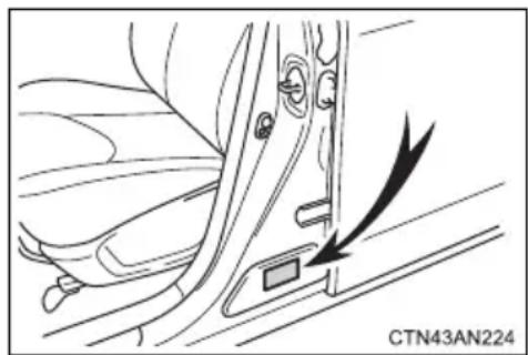
natural_image
Diagram of a car interior showing a door and seat, with a black arrow indicating direction (no text or symbols present)For the GAWR, see the Certification Label. For the maximum load of the tire, see the load limit at maximum cold tire inflation pressure mentioned on the sidewall of the tire. (→P. 489)
Tire types
●Summer tires
Summer tires are high-speed performance tires best suited to highway driving under dry conditions. Since summer tires do not have the same traction performance as snow tires, summer tires are inadequate for driving on snow-covered or icy roads. For driving on snow-covered roads or icy roads, the use of snow tires is recommended. When installing snow tires, be sure to replace all four tires.
●All season tires
All season tires are designed to provide better traction in snow and to be adequate for driving in most winter conditions as well as for use year-round. All season tires, however, do not have adequate traction performance compared with snow tires in heavy or loose snow. Also, all season tires fall short in acceleration and handling performance compared with summer tires in highway driving.
●Snow tires
For driving on snow-covered roads or icy roads, we recommend using snow tires. If you need snow tires, select tires of the same size, construction and load capacity as the originally installed tires. Since your vehicle has radial tires as original equipment, make sure your snow tires also have radial construction. Do not install studded tires without first checking local regulations for possible restrictions. Snow tires should be installed on all wheels. ( P. 268)
If the tread on snow tires wears down below 0.16 in. (4 mm)
The effectiveness of the tires as snow tires is lost.
■Tire pressure warning system certification
U.S.A.
FCC ID: PAXPMV107J
FCC ID: HYQ13BCX
NOTE:
This device complies with part 15 of the FCC Rules. Operation is subject to the following two conditions: (1) This device may not cause harmful interference, and (2) this device must accept any interference received, including interference that may cause undesired operation.
FCC WARNING:
Changes or modifications not expressly approved by the party responsible for compliance could void the user's authority to operate the equipment.
Canada
NOTE:
Operation is subject to the following two conditions: (1) this device may not cause interference, and (2) this device must accept any interference, including interference that may cause undesired operation of the device.
NOTE:
■To prevent damage to the vehicle
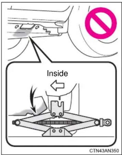
- Do not use a tire jack because its arms may interfere with the traction battery in the vehicle underbody.
- Forcibly using a tire jack may damage the traction battery or cause the vehicle to fall off the jack, resulting in death or serious injury.
■Replacing a tire
-
Do not try to remove the ornament by hand. Take due care in handling the ornament to avoid unexpected personal injury.
●Failure to follow these precautions could cause the wheel nuts to loosen and the tire to fall off, resulting in death or serious injury. -
Have the wheel nuts tightened with a torque wrench to 76 ft·lbf (103 N·m, 10.5 kgf·m) as soon as possible after changing wheels.
- Do not attach a heavily damaged wheel ornament, as it may fly off the wheel while the vehicle is moving.

CAUTION
■When inspecting or replacing tires
Observe the following precautions to prevent accidents. Failure to do so may cause damage to parts of the drive train, as well as dangerous handling characteristics, which may lead to an accident resulting in death or serious injury.
- Do not mix tires of different makes, models or tread patterns. Also, do not mix tires of remarkably different treadwear.
- Do not use tire sizes other than those recommended by Toyota.
- Do not mix differently constructed tires (radial, bias-belted or bias-ply tires).
- Do not mix summer, all season and snow tires.
- Do not use tires that have been used on another vehicle. Do not use tires if you do not know how they were used previously.

NOTICE
■Repairing or replacing tires, wheels, tire pressure warning valves, transmitters and tire valve caps
- When removing or fitting the wheels, tires or the tire pressure warning valves and transmitters, contact your Toyota dealer as the tire pressure warning valves and transmitters may be damaged if not handled correctly.
- When replacing tire valve caps, do not use tire valve caps other than those specified. The cap may become stuck.
■To avoid damage to the tire pressure warning valves and transmitters
When a tire is repaired with liquid sealants, the tire pressure warning valve and transmitter may not operate properly. If a liquid sealant is used, contact your Toyota dealer or other qualified service shop as soon as possible. Make sure to replace the tire pressure warning valve and transmitter when replacing the tire. (→P. 367)

NOTICE
■ Driving on rough roads
Take particular care when driving on roads with loose surfaces or pot-holes.
These conditions may cause losses in tire inflation pressure, reducing the cushioning ability of the tires. In addition, driving on rough roads may cause damage to the tires themselves, as well as the vehicle's wheels and body.
If tire inflation pressure of each tire becomes low while driving
Do not continue driving, or your tires and/or wheels may be ruined.
■Tire inflation pressure
The recommended cold tire inflation pressure and tire size are displayed on the tire and loading information label. ( P. 489)
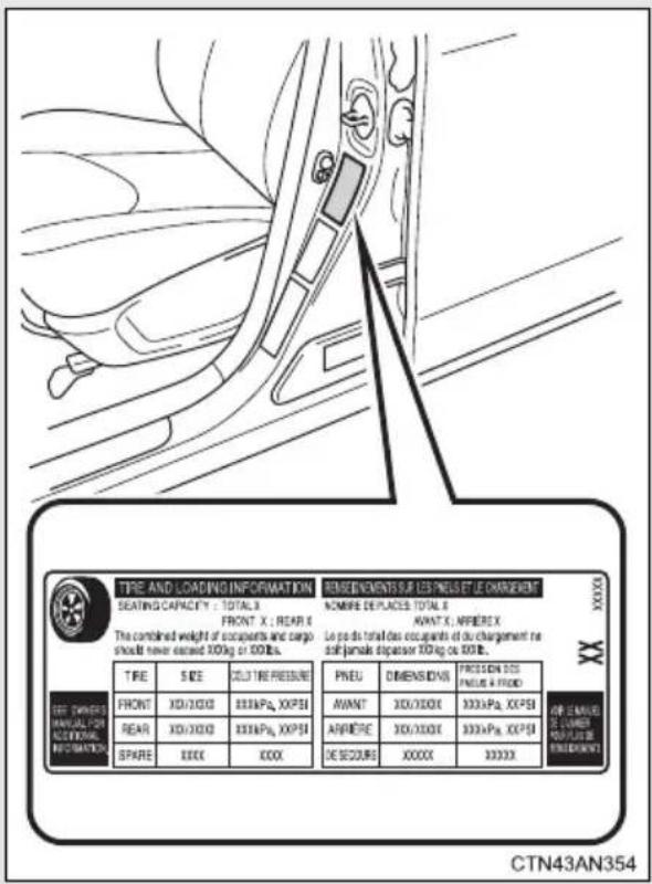
■Inspection and adjustment procedure
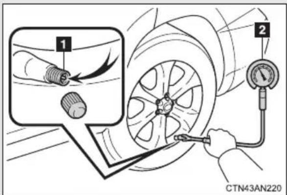
1 Tire valve
2 Tire pressure gauge
STEP 1 Remove the tire valve cap.
STEP 2 Press the tip of the tire pressure gauge onto the tire valve.
STEP 3 Read the pressure using the gauge gradations.
STEP 4 If the tire inflation pressure is not at the recommended level, adjust the pressure.
If you add too much air, press the center of the valve to deflate.
STEP 5 After completing the tire inflation pressure measurement and adjustment, apply soapy water to the valve and check for leakage.
STEP 6 Put the tire valve cap back on.
■Tire inflation pressure check interval
You should check tire inflation pressure every two weeks, or at least once a month.
■Effects of incorrect tire inflation pressure
Driving with incorrect tire inflation pressure may result in the following:
●Reduced traction battery efficiency
●Reduced driving comfort and tire life
●Reduced safety
●Damage to the drive train
If a tire needs frequent inflating, have it checked by your Toyota dealer.
■Instructions for checking tire inflation pressure
When checking tire inflation pressure, observe the following:
- Check only when the tires are cold.
If your vehicle has been parked for at least 3 hours or has not been driven for more than 1 mile or 1.5 km, you will get an accurate cold tire inflation pressure reading.
●Always use a tire pressure gauge.
The appearance of the tire can be misleading. In addition, tire inflation pressure that is even just a few pounds off can affect ride quality and handling. - Do not reduce tire inflation pressure after driving. It is normal for tire inflation pressure to be higher after driving.
●Never exceed the vehicle capacity weight.
Passengers and luggage weight should be placed so that the vehicle is balanced.

CAUTION
■ Proper inflation is critical to save tire performance
Keep your tires properly inflated.
Otherwise, the following conditions may occur and result in an accident causing death or serious injury:
Excessive wear
Uneven wear
●Poor handling
● Possibility of blowouts resulting from overheated tires
●Poor sealing of the tire bead
●Wheel deformation and/or tire separation
●A greater possibility of tire damage from road hazards

NOTICE
■When inspecting and adjusting tire inflation pressure
Be sure to put the tire valve caps back on.
Without the valve caps, dirt or moisture could get into the valve and cause air leakage, which could result in an accident. If the caps are lost, replace them as soon as possible.
If a wheel is bent, cracked or heavily corroded, it should be replaced.
Otherwise, the tire may separate from the wheel or cause a loss of handling control.
Wheel selection
When replacing wheels, care should be taken to ensure that they are equivalent to those removed in load capacity, diameter, rim width and inset*.
Replacement wheels are available at your Toyota dealer.
*: Conventionally referred to as "offset".
Toyota does not recommend using the following:
●Wheels of different sizes or types
●Used wheels
●Bent wheels that have been straightened
■ Aluminum wheel precautions
- Use only Toyota wheel nuts and wrenches designed for use with your aluminum wheels.
- When rotating, repairing or changing your tires, check that the wheel nuts are still tight after driving 1000 miles (1600 km).
- Be careful not to damage the aluminum wheels when using tire chains.
- Use only Toyota genuine balance weights or equivalent and use a plastic or rubber hammer when balancing your wheels.
■When replacing wheels
The wheels of your vehicle are equipped with tire pressure warning valves and transmitters that allow the tire pressure warning system to provide advance warning in the event of a loss in tire inflation pressure. Whenever wheels are replaced, the tire pressure warning valves and transmitters must be installed. ( P. 367)

CAUTION
■When replacing wheels
- Do not use wheels that are a different size from those recommended in the Owner's Manual, as this may result in a loss of handling control.
●Never use an inner tube in a leaking wheel which is designed for a tubeless tire. Doing so may result in an accident, causing death or serious injury.
■When installing the wheel nuts
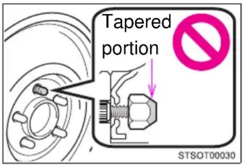
- Be sure to install the wheel nuts with the tapered ends facing inward. Installing the nuts with the tapered ends facing outward can cause the wheel to break and eventually cause the wheel to come off while driving, which could lead to an accident resulting in death or serious injury.
● Never use oil or grease on the wheel bolts or wheel nuts. Oil and grease may cause the wheel nuts to be excessively tightened, leading to bolt or disc wheel damage. In addition, the oil or grease can cause the wheel nuts to loosen and the wheel may fall off, causing an accident and resulting in death or serious injury. Remove any oil or grease from the wheel bolts or wheel nuts.

NOTICE
■Replacing tire pressure warning valves and transmitters
● Because tire repair or replacement may affect the tire pressure warning valves and transmitters, make sure to have tires serviced by your Toyota dealer or other qualified service shop. In addition, make sure to purchase your tire pressure warning valves and transmitters at your Toyota dealer.
- Ensure that only genuine Toyota wheels are used on your vehicle. Tire pressure warning valves and transmitters may not work properly with non-genuine wheels.
The air conditioning filter must be changed regularly to maintain air conditioning efficiency.
Removal method
STEP 1 Turn the "POWER" switch off.
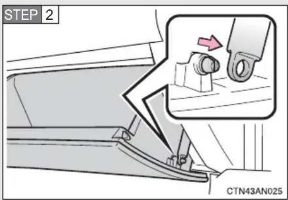
Open the glove box. Slide off the damper.
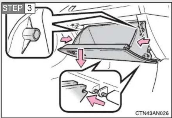
Push in each side of the glove box to disconnect the claws.
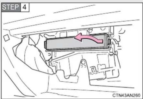
Remove the filter cover.
■Replacement method
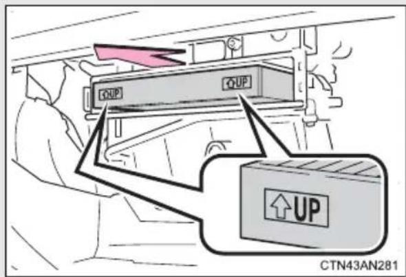
Remove the air conditioning filter and replace it with a new one.
The “↑UP” marks shown on the filter should be pointing up.
- Checking interval
Inspect and replace the air conditioning filter according to the maintenance schedule. In dusty areas or areas with heavy traffic flow, early replacement may be required. (For scheduled maintenance information, please refer to the "Scheduled Maintenance Guide" or "Owner's Manual Supplement".)
If air flow from the vents decreases dramatically
The filter may be clogged. Check the filter and replace if necessary.

CAUTION
■When replacing the air conditioning filter
Do not use pre-climate. Doing so may cause the air conditioning system to operate during the procedure and you could get caught in moving parts such as the blower fan, possibly resulting in injury.

NOTICE
■When using the air conditioning system
Make sure that a filter is always installed.
Using the air conditioning system without a filter may cause damage to the system.
Replace the battery with a new one if it is depleted.
■You will need the following items:
●Flathead screwdriver
●Small flathead screwdriver
●Lithium battery CR1632
■Replacing the battery
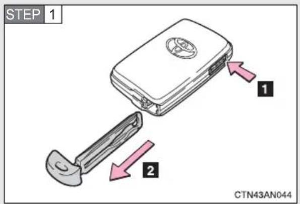
Take out the mechanical key.
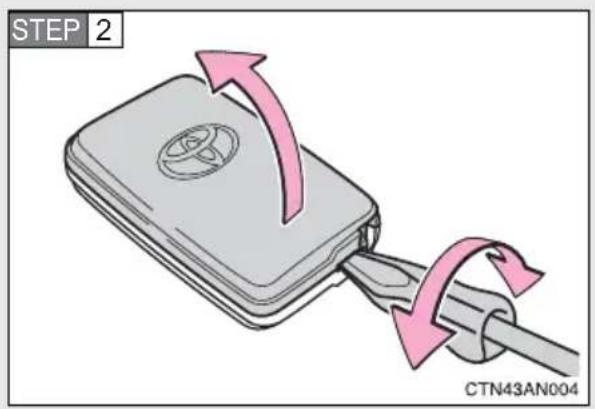
Remove the cover.
To prevent damage to the key, cover the tip of the screwdriver with a rag.
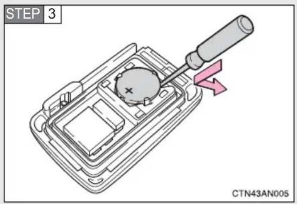
Remove the depleted battery.
Insert a new battery with the “+” terminal facing up.
■Use a CR1632 lithium battery
●Batteries can be purchased at your Toyota dealer, local electrical appliance shops or camera stores.
- Replace only with the same or equivalent type recommended by the manufacturer.
● Dispose of used batteries according to local laws.
■If the electronic key battery is depleted
The following symptoms may occur.
●The smart key system and wireless remote control will not function properly.
●The operational range will be reduced.

CAUTION
■Removed electronic key battery and other parts
These parts are small and if swallowed by a child, they can cause choking. Keep away from children. Failure to do so could result in death or serious injury.

NOTICE
For normal operation after replacing the electronic key battery
Observe the following precautions to prevent accidents.
●Always work with dry hands.
Moisture may cause the battery to rust.
- Do not touch or move any other component inside the remote control.
- Do not bend either of the battery terminals.
4-3. Do-it-yourself maintenance
Checking and replacing fuses
If any of the electrical components do not operate, a fuse may have blown. If this happens, check and replace the fuses as necessary.
STEP 1 Turn the "POWER" switch off.
STEP 2 Open the fuse box cover.
Motor compartment
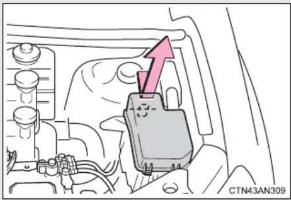
natural_image
Diagram of a car engine compartment with a highlighted component and an upward arrow (no text or symbols)Type A: Push the tab in and lift the lid off.
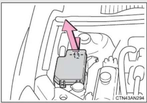
Type B: Push the tab in and lift the lid off.
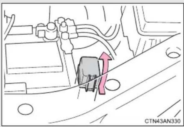
Type C: Push the tab in and lift the lid off.
Under the instrument panel
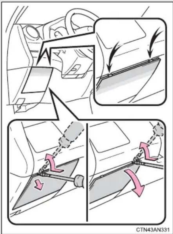
Front side of the fuse block: Remove the cover.
To prevent damaging the vehicle, wrap the flathead screwdriver with tape.
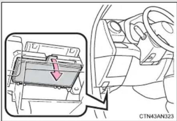
Fuse block (under side view): Remove the lid.
STEP 3 After a system failure, see “Fuse layout and amperage ratings” (→P. 389) for details about which fuse to check.
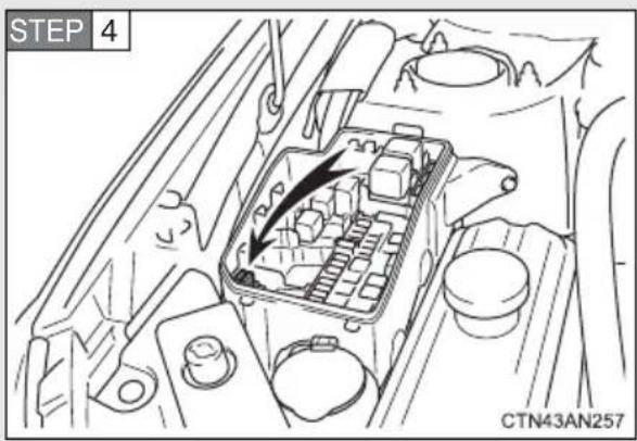
Only type A fuse can be removed using the pullout tool.
STEP 5 Check if the fuse is blown.
Type A
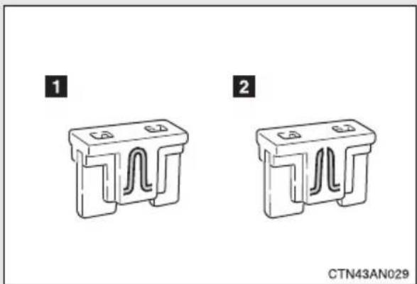
natural_image
Two identical 3D component diagrams labeled 1 and 2, showing internal channels (no text or symbols on the components themselves)1 Normal fuse
2 Blown fuse
Replace the blown fuse with a new fuse of an appropriate amperage rating. The amperage rating can be found on the fuse box lid.
Type B
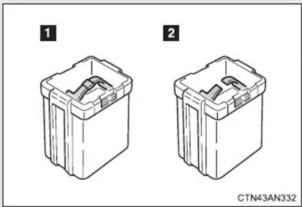
natural_image
Two technical line drawings of a mechanical component with internal slots, labeled 1 and 2 (no text or symbols on the components themselves)1 Normal fuse
2 Blown fuse
Replace the blown fuse with a new fuse of an appropriate amperage rating. The amperage rating can be found on the fuse box lid.
Type C
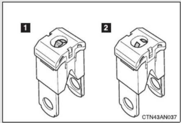
natural_image
Technical line drawings of two mechanical components with mounting holes, labeled 1 and 2 (no text or symbols on the components themselves)1 Normal fuse
2 Blown fuse
Contact your Toyota dealer.
Type D
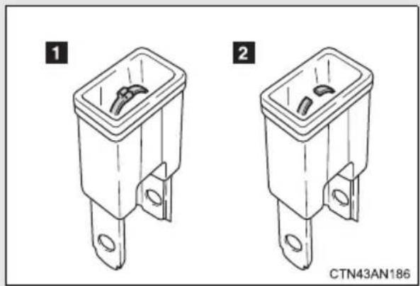
natural_image
Two technical line drawings of a rectangular electronic component with mounting holes, labeled 1 and 2 (no text or symbols on the components themselves)1 Normal fuse
2 Blown fuse
Contact your Toyota dealer.
Fuse layout and amperage ratings
■Motor compartment
Type A (driver's side)
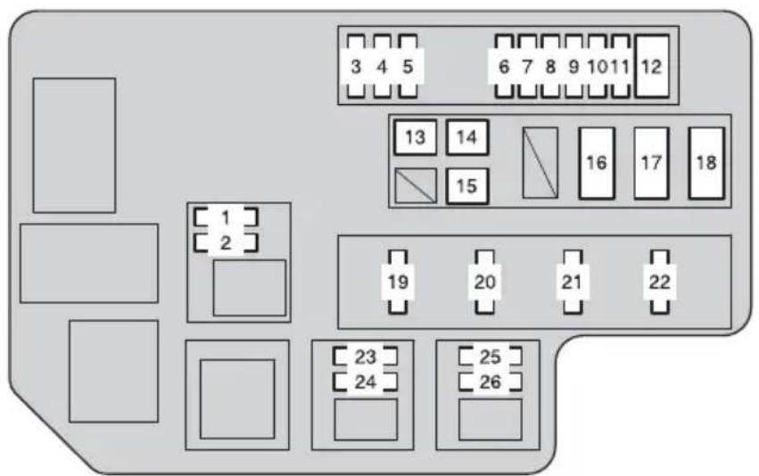
CTN43AN324
| Fuse Ampere Circuit | ||
| 1 INV MTR 10 A Inverter motor | ||
| 2 IGDI 1 10 A | Traction battery, multiplex communication system, thermal control system | |
| 3 BATT W/P 1 15 A Traction battery | ||
| 4 BATT W/P 2 15 A Traction battery | ||
| 5 P/T W/P 15 A Cooling system | ||
| 6 IGDI MAIN 20 A INV MTR, IGDI 1 | ||
| 7 HAZ 15 A Emergency flashers | ||
| 8 IGCT 3 20 A | PM-IGCT, P CNT-IGCT, A/C-IGCT, FAN-IGCT | |
| 9 G/W-B | 10 A Multiplex communication system | |
| 10 RADIO | 30 A Audio system | |
| 11 P CNT-B 7.5 A | Parking control system | |
| Fuse | Ampere | Circuit | |
| 12 | ABS 1 30 A Anti-lock | brake system | |
| 13 | ECB 1 50 A | Electronically controlled brake sys-tem | |
| 14 | ECB 2 50 A | Electronically controlled brake sys-tem | |
| 15 | W/P-IGCT 50 A P/T | W/P, BATT | W/P 1, BATT W/P 2 |
| 16 | EPS 60 A Electric power steering | ||
| 17 | P/I | IGCT-D, HORN, parking control system, IG2A | |
| 18 | MAIN | H-LP MAIN, DRL, ODS, smart key system, ABS 2, steering lock sys-tem, PM-B, ECU-B MAIN | |
| 19 | CONTACTOR 15 A | Traction battery, charging system | |
| 20 | IG2 | 15 A | |
| 21 | HORN 10 A Horn | ||
| 22 | IGCT-D 7.5 A | Thermal control system, power management ECU, parking control system, multiplex communication system | |
| 23 | PM-IGCT 7.5 A | Power management system | |
| 24 | P CNT-IGCT | 7.5 A Parking control system | |
| 25 | A/C-IGCT | 10 A Air conditioning system | |
| 26 | FAN-IGCT | 7.5 A Electric cooling fans | |
Sti
Type B (passenger's side)
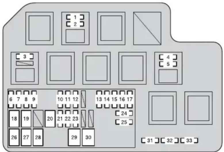
CTN43AN325
| Fuse Ampere Circuit | |||
| 1 | THRML CTRL 10 A | Thermal control system | |
| 2 | G/W-IGCT 10 A Multiplex communication system | ||
| 3 | DRL 7.5 A Daytime running light system | ||
| 4 | ECU-B 2 7.5 A Air conditioning system | ||
| 5 | A/C-B 7.5 A | Gauges and meters, steering sensor | |
| 6 | H-LP LH-LO 10 A Left-hand headlight (low beam) | ||
| 7 | H-LP RH-LO 10 A Right-hand headlight (low beam) | ||
| 8 | H-LP LH-HI 10 A Left-hand headlight (high beam) | ||
| 9 | H-LP RH-HI | 10 A Right-hand headlight (high beam) | |
| 10 | DOME | 7.5 A | Foot lights, vanity lights, interior lights, personal lights, luggage compartment light |
| 11 | ECU-B 1 7.5 A | Anti-glare inside rear view mirror, smart key system | |
| 12 | DCM-B | 7.5 A DCM-B | |
| 13 | P CNT MTR | 30 A Parking control system | |
| Fuse Ampere | Circuit | ||
| 14 SMART 7.5 A Smart | key system | ||
| 15 STRG LOCK 20 A | steering lock | system | |
| 16 AM2 7.5 A Starting system | |||
| 17 ABS 2 7.5 A Anti-lock brake system | |||
| 18 PTC HTR 2 50 A Air | conditioning | system | |
| 19 PTC HTR 1 50 A Air | conditioning | system | |
| 20 PTC HTR 3 50 A Air | conditioning | system | |
| 21 CHARGER 5 A Charging system | |||
| 22 IGCT 2 20 A THRML | CTRL, G/W-IGCT | ||
| 23 HV BATT 10 A Traction battery | |||
| 24 PM-B 7.5 A Power management | system | ||
| 25 ODS 7.5 A Occupant classification system | |||
| 26 HTR | 50 A Air conditioning system | ||
| 27 FAN 1 | 50 A Electric cooling fans | ||
| 28 FAN 2 | 50 A Electric cooling fans | ||
| 29 H-LP MAIN | 40 A | H-LP LH-LO, H-LP RH-LO, H-LP LH-HI, H-LP RH-HI, manual head-light leveling system, daytime running light system | |
| 30 ECU-B MAIN | 30 A ECU-B 2, A/C-B | ||
| 31 SPARE | 5 A Spare fuse | ||
| 32 SPARE | 10 A Spare fuse | ||
| 33 SPARE | 20 A Spare fuse | ||
Type C
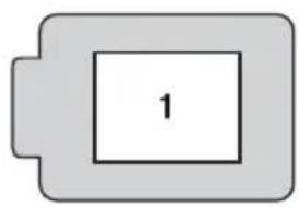
natural_image
Simple diagram of a battery with one cell labeled '1' (no text or symbols beyond the number)CTN43AN226
| Fuse Ampere Circuit | |||
| 1 FL J/B 140 A | ECU-IG1 2, back-up lights, wind-shield wipers and washers, rear window wiper and washer, ECU-IG1 1, seat heaters, ECU-IG1 3, power windows, stop lights, OBD, ACC-MAIN, charging indicator, DEF, TAIL, power outlets, switch illumination, instrument panel lights, gauges and meters, audio system, air conditioning system | ||
■Under the instrument panel
Front side of the fuse block
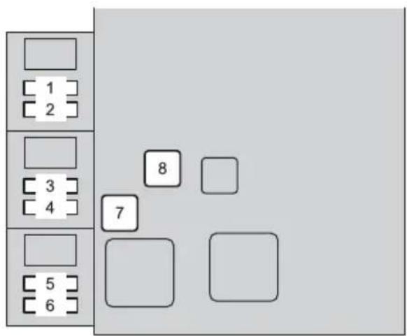
CTN43AN326
| Fuse Ampere Circuit | |||
| 1 D | CM-IG2 5 A DCM-IG2 | ||
| 2 P | M-IG2 5 A Power management system | ||
| 3 IG2 2 5 A | Steering lock system, smart key system | ||
| 4 IG2 1 5 A | Electronically controlled brake sys-tem, stop/tail lights, high mounted stoplight | ||
| 5 S | SR-IG1 5 A | Vehicle stability control system, steering sensor | |
| 6 E | PS-IG1 5 A Electric power steering | ||
| 7 P | W-MAIN 30 A Power windows | ||
| 8 D | EF 30 A Rear window defogger | ||
Fuse block (under side view)
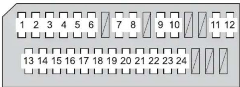
CTN43AN327
| Fuse Ampere Circuit | |||
| 1 T | TAIL 10 A | Tail lights, license plate light, side marker lights, daytime running light system | |
| 2 P | ANEL 7.5 A Switch | illuminations | |
| 3 B | KUP LP 10 A Back-up lights | ||
| 4 P | /W-FL 20 A Power windows | ||
| 5 P | /W-RL 20 A Power windows | ||
| 6 P | /W-RR 20 A Power windows | ||
| 7 P | /OUT 15 A Power outlet | ||
| 8 ACC-B 7.5 A | Audio system, power rear view mir- ror control, air conditioning sys- tem, smart key system, main body ECU | ||
| 9 MIR HTR | 10 A Outside rear view mirror defoggers | ||
| 10 | P/OUT-MAIN | 15 A Power outlets | |
| 11 | A/B-IG2 7.5 A SRS airbag system | ||
| 12 | GAUGE | 7.5 A Gauges and meters | |
| 13 | ECU-IG1 3 | 10 A EPS-IG1, SSR-IG1 | |
| 14 | S/HTR | 15 A Seat heaters | |
| 15 | WIPER | 25 A Windshield wipers | |
| 16 | WIPER RR | 15 A Rear window wiper | |
| Fuse Ampere Circuit | |||
| 17 | WASHER 15 A | Windshield washer, rear window washer | |
| 18 | ECU-IG1 1 10 A | Electronically controlled brake system, tire pressure warning system, air conditioning system, main body ECU, anti-glare inside rear view mirror, Vehicle Proximity Notification System, navigation system | |
| 19 | ECU-IG1 2 10 A | Emergency flashers, rear window defogger, air conditioning system | |
| 20 | OBD 7.5 A On-board diagnosis system | ||
| 21 | STOP 10 A | Stop/tail lights, high mounted stop-light | |
| 22 | CHRG IND 7.5 A Charging indicator | ||
| 23 | DOOR 25 A Power windows | ||
| 24 | ACC-MAIN 25 A ACC-B, P/OUT, DCM | ||
■After a fuse is replaced
- If the lights do not turn on even after the fuse has been replaced, a bulb may need replacement. (→P. 400)
- If the replaced fuse blows again, have the vehicle inspected by your Toyota dealer.
If there is an overload in a circuit
The fuses are designed to blow, protecting the wiring harness from damage.
■When replacing light bulbs
Toyota recommends that you use genuine Toyota products designed for this vehicle.
Because certain bulbs are connected to circuits designed to prevent overload, non-genuine parts or parts not designed for this vehicle may be unusable.

CAUTION
■To prevent system breakdowns and vehicle fire
Observe the following precautions.
Failure to do so may cause damage to the vehicle, and possibly a fire or injury.
●Never use a fuse of a higher amperage rating than that indicated, or use any other object in place of a fuse.
●Always use a genuine Toyota fuse or equivalent.
Never replace a fuse with a wire, even as a temporary fix.
- Do not modify the fuses or fuse boxes.

NOTICE
■Before replacing fuses
Have the cause of electrical overload determined and repaired by your Toyota dealer as soon as possible.
■Vertical movement adjusting bolts
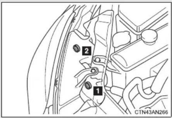
1 Adjustment bolt A
2 Adjustment bolt B
■Before checking the headlight aim
STEP 1 Make sure the area around the headlight is not deformed.
STEP 2 Park the vehicle on level ground.
STEP 3 Sit in the driver's seat.
STEP 4 Adjust the manual headlight leveling dial position to 0.
STEP 5 Bounce the vehicle several times.
■Adjusting the headlight aim
STEP 1 Remove the motor compartment cover. (→P. 356)
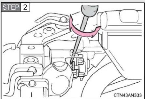
Using a Phillips-head screw-driver, turn bolt A in either direction.
Remember the turning direction and the number of turns.
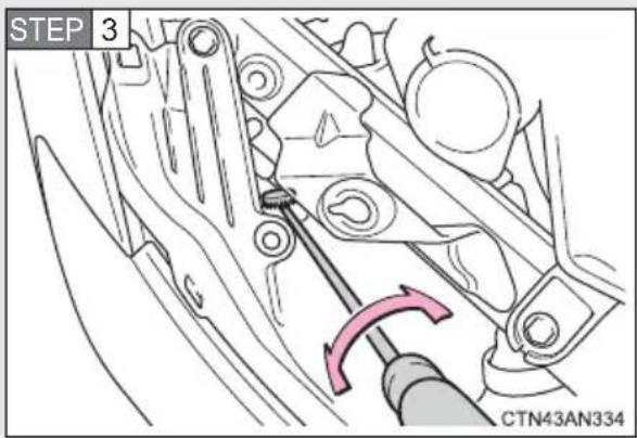
Turn bolt B the same number of turns and in the same direction as step 2.
If the headlight cannot be adjusted using this procedure, take the vehicle to your Toyota dealer to adjust the headlight aim.
You may replace the following bulbs by yourself. The difficulty level of replacement varies depending on the bulb. If necessary bulb replacement seems difficult to perform, contact your Toyota dealer.
For more information about replacing other light bulbs, contact your Toyota dealer.
■Preparing for light bulb replacement
Check the wattage of the light bulb to be replaced. (→P. 488)
■Removing the motor compartment cover
→P. 356
■Front bulb locations
Front turn signal
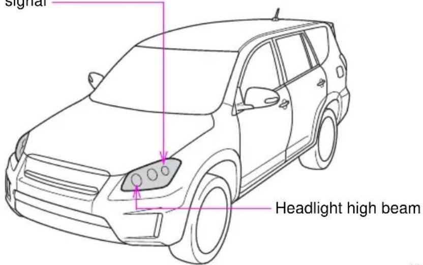
CTN43AN295
■Rear bulb locations
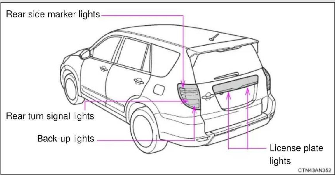
Replacing light bulbs
■Headlight high beams
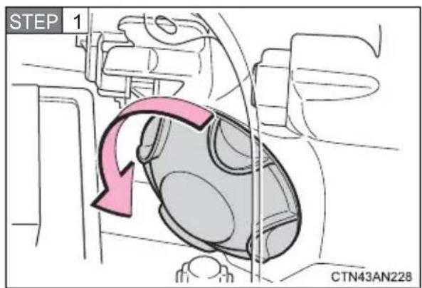
Turn the cover counterclockwise and remove it.
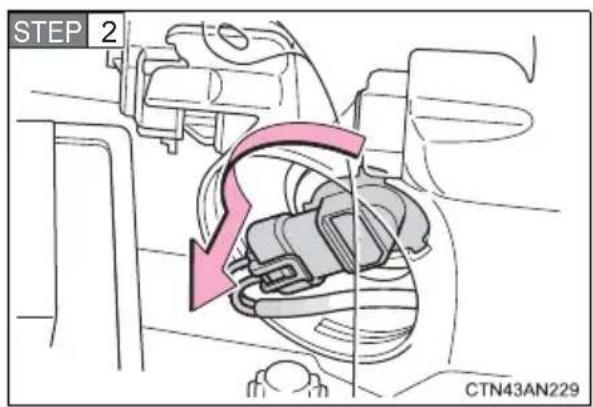
Turn the bulb base counterclockwise.
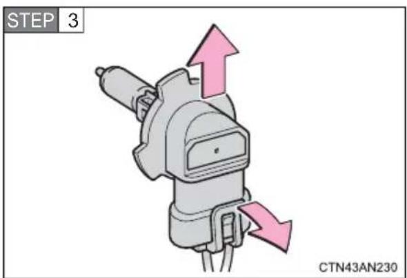
Unplug the connector while pulling the lock release.
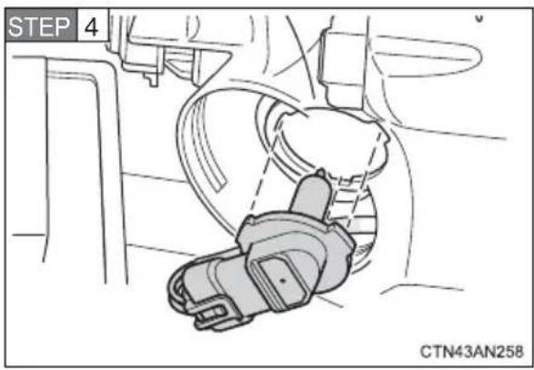
Replace the light bulb and install the bulb base.
Align the 3 tabs on the light bulb with the mounting, and insert.
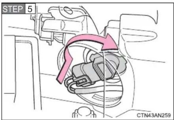
Turn and secure the bulb base.
Shake the bulb base gently to check that it is not loose, turn the headlight high beams on once and visually confirm that no light is leaking through the mounting.
Front turn signal
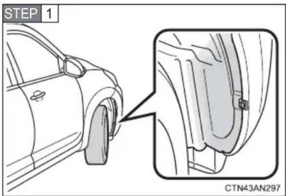
Turn the steering wheel in the opposite direction of the front turn signal that you wish to replace.
For example, if you wish to replace the front turn signal on the right side, turn the steering wheel to the left.
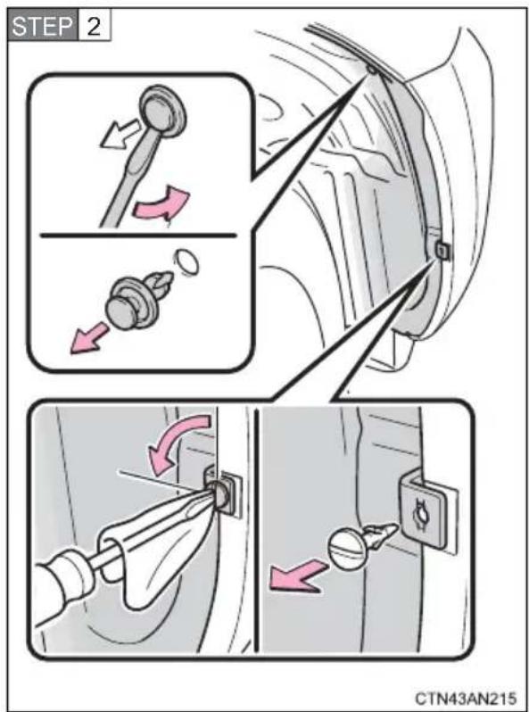
Remove the clips using a flat-head screwdriver.
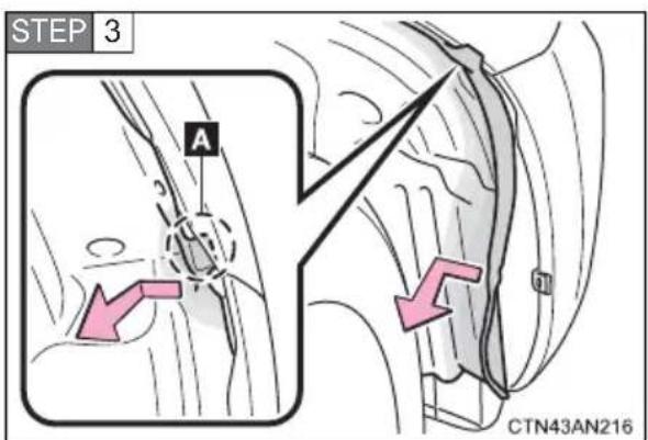
Move section "A" of the fender liner to the inner side of the vehicle, partly removing it and thereby allowing access to the front turn signal.
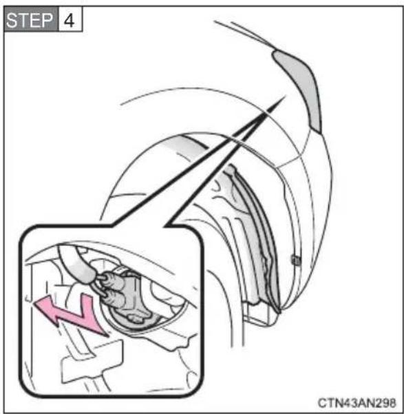
Turn the bulb base counterclockwise.
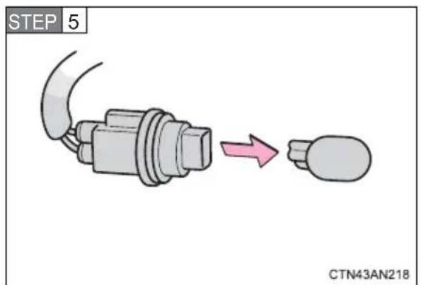
Remove the light bulb.
■Back-up lights, rear turn signal and rear side marker lights
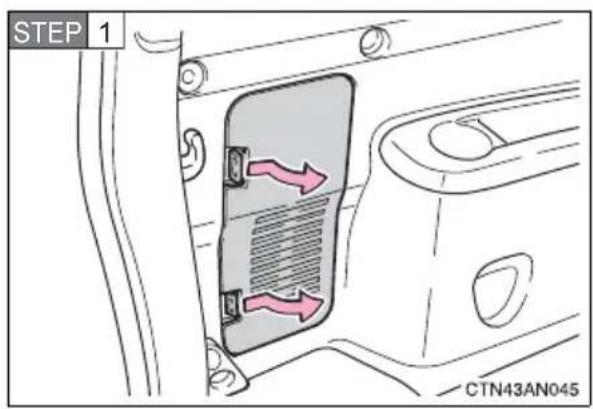
Open the back door ( P. 113) and remove the cover.
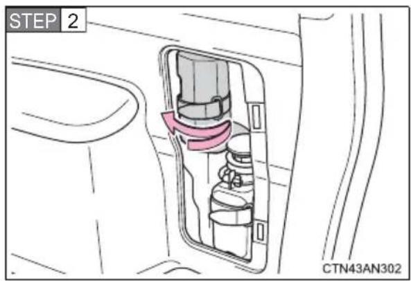
Right side only:
Remove the emergency tire puncture repair kit's compressor.
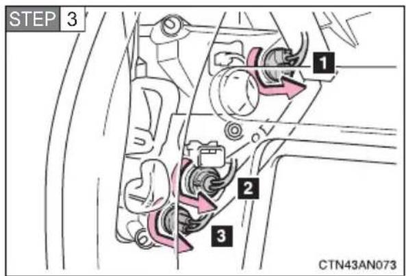
Turn the bulb base counterclockwise.
1 Rear side marker light
2 Rear turn signal light
3 Back-up light
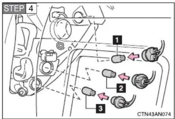
Remove the light bulb.
1 Rear side marker light
2 Rear turn signal light
3 Back-up light
License plate lights
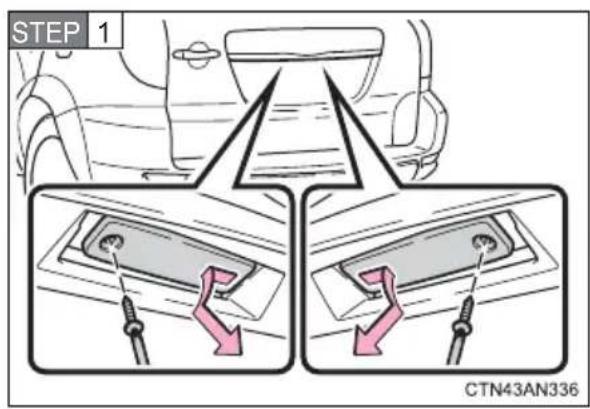
Remove the cover as shown in the illustration.
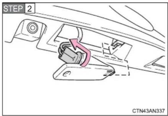
Turn the bulb base counterclockwise.
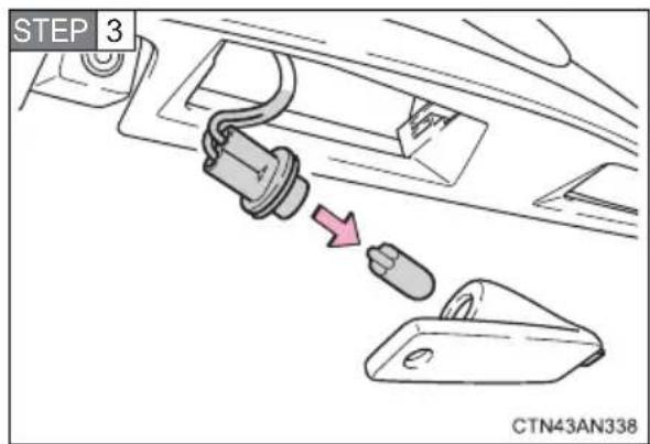
Remove the light bulb.
■Replacing the following lights
If any of the lights listed below has burnt out, have it replaced by your Toyota dealer.
●Headlight low beams
●Daytime running/parking lights
●Front side marker lights
●Side turn signal lights
- Stop/tail lights
●High mounted stoplight
LED lights
The headlight low beams, daytime running/parking lights, front side marker lights, stop/tail lights and high mounted stoplight consists of a number of LEDs. If any of the LEDs burn out, take your vehicle to your Toyota dealer to have the light replaced.
■Condensation build-up on the inside of the lens
Temporary condensation build-up on the inside of the headlight lens does not indicate a malfunction.
Contact your Toyota dealer for more information in the following situations:
●Large drops of water have built up on the inside of the lens.
●Water has built up inside the headlight.
■ Replacing the back-up light, rear turn signal and rear side marker light bulbs
There is a ECU near the left hand side bulb bases.
When removing the bulb base, make sure to not subject the ECU to impacts.
(→P. 319)
■When replacing light bulbs
→P. 397

CAUTION
■Replacing light bulbs
●Turn off the lights. Do not attempt to replace the bulb immediately after turning off the lights.
The bulbs become very hot and may cause burns.
- Do not touch the glass portion of the light bulb with bare hands. Hold the bulb by the plastic or metal portion.
If the bulb is scratched or dropped, it may blow out or crack.
● Fully install light bulbs and any parts used to secure them. Failure to do so may result in heat damage, fire, or water entering the headlight unit. This may damage the headlights or cause condensation to build up on the lens.
■To prevent damage or fire
Make sure bulbs are fully seated and locked.
4-3. Do-it-yourself maintenance
5-1. Essential information
Emergency flashers ..... 412
If your vehicle needs to be towed 413
If you think something is wrong 416
5-2. Steps to take in an emergency
If a warning light turns on or a warning buzzer sounds... 417
If a warning message is displayed.... 427
If you have a flat tire...... 447
If the EV (Electric Vehicle) system will not start ..... 465
If you lose your keys ..... 467
If the electronic key does not operate properly 468
If the vehicle 12-volt battery is discharged..... 470
If your vehicle overheats.... 475
If the vehicle becomes stuck 477
If your vehicle has to be stopped in an emergency.... 479
5-1. Essential information Emergency flashers
The emergency flashers are used to warn other drivers when the vehicle has to be stopped in the road due to a breakdown, etc.
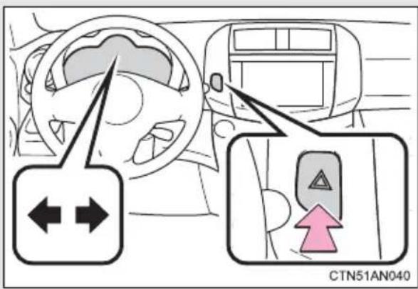
Press the switch.
All the turn signal lights will flash. To turn them off, press the switch once again.
Emergency flashers
If the emergency flashers are used for a long time while the EV system is not operating (while the "READY" indicator is not illuminated), the 12-volt battery may discharge.
If towing is necessary, we recommend having your vehicle towed by your Toyota dealer or a commercial towing service, using a lift-type truck or flatbed truck.
Use a safety chain system for all towing, and abide by all state/provincial and local laws.
Before towing
The following may indicate a problem with your transmission. Contact your Toyota dealer before towing.
● The EV system is operating but the vehicle will not move.
●The vehicle makes an abnormal sound.
If there is a malfunction in the P position control system, or if the 12-volt battery is discharged, the vehicle cannot be moved with the front wheels on the ground, as the front wheels may be locked.
In this case, move the vehicle with both front wheels or all four wheels lifted.
Jump start procedure ( P. 470)
Towing with a sling-type truck
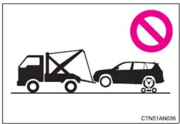
Do not tow with a sling-type truck to prevent body damage.
Towing with a wheel-lift type truck
From the front
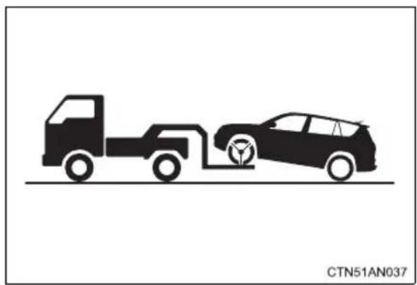
natural_image
Silhouette illustration of a truck and car with a charging plug, no text or symbols presentRelease the parking brake.
From the rear
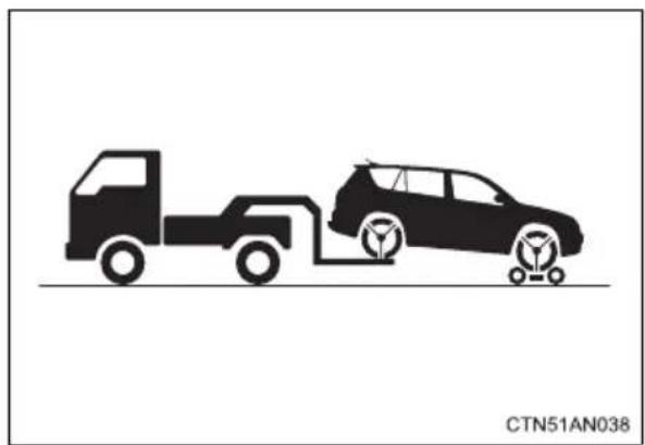
natural_image
Silhouette illustration of a truck and car with wheels, no text or symbols presentUse a towing dolly under the front wheels.
Using a flat bed truck
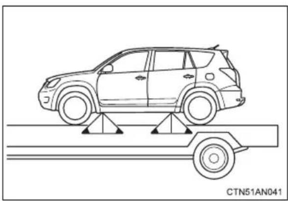
natural_image
Line drawing of a car on a road with support structures (no text or symbols)If you use chains or cables to tie down your vehicle, the angles shaded in black must be 45^ .
Do not overly tighten the tie downs or the vehicle may be damaged.

NOTICE
■ To prevent damage to the vehicle when towing using a wheel-lift type truck
When raising the vehicle, ensure adequate ground clearance for towing at the opposite end of the raised vehicle. Without adequate clearance, the vehicle could be damaged while being towed.
■To prevent body damage when towing with a sling-type truck
Do not tow with a sling-type truck, either from the front or rear.
To prevent causing serious damage to the EV system when towing using a wheel-lift type truck
Never tow this vehicle from the rear with the front wheels on the ground. Doing so can lead to EV system damage.
If you notice any of the following symptoms, your vehicle probably needs adjustment or repair. Contact your Toyota dealer as soon as possible.
■Visible symptoms
●Fluid leaks under the vehicle
(Water dripping from the air conditioning after use is normal.)
●Flat-looking tires or uneven tire wear
Audible symptoms
●Excessive tire squeal when cornering
●Strange noises related to the suspension system
■Operational symptoms
●Stumbling or running roughly
●Appreciable loss of power
●Vehicle pulls heavily to one side when braking
●Vehicle pulls heavily to one side when driving on a level road
- Loss of brake effectiveness, spongy feeling, pedal almost touches the floor
Calmly perform the following actions if any of the warning lights comes on or flashes. If a light comes on or flashes, but then goes off, this does not necessarily indicate a malfunction in the system. However, if this continues to occur, have the vehicle inspected by your Toyota dealer.
Stop the vehicle immediately. Continuing to drive the vehicle may be dangerous.
The following warning indicates a possible problem in the brake system. Immediately stop the vehicle in a safe place and contact your Toyota dealer.
| Warning light W | Warning light/Details |
 (Red) (Red) | Brake system warning light (warning buzzer)*Low brake fluidMalfunction in the brake systemThis light also comes on when the parking brake is not released. If the light turns off after the parking brake is fully released the system is operating normally. |
\*: Brake system warning buzzer:
When there is a possible problem that could affect braking performance, the warning light will come on and a warning buzzer may sound.
Parking brake engaged warning buzzer:
→P. 433
■Brake system warning light operation
Although depressing the brake pedal repeatedly may cause the red brake system warning light to turn on and the buzzer to sound, this does not indicate a malfunction.
Stop the vehicle immediately.
The following warning indicates the possibility of damage to the vehicle that may lead to an accident. Immediately stop the vehicle in a safe place and contact your Toyota dealer.
| Warning light W | Warning light/Details |
 | 12-volt battery charging system warning lightIndicates a malfunction in the vehicle’s 12-volt battery charging system. |
Have the vehicle inspected by your Toyota dealer immediately.
Failure to investigate the cause of the following warnings may lead to the system operating abnormally and possibly cause an accident. Have the vehicle inspected by your Toyota dealer immediately.
| Warning light | Warning light/Details |
 | SRS warning lightIndicates a malfunction in:The SRS airbag system;The front passenger occupant classification system; orThe seat belt pretensioner system. |
 | “ABS” warning lightIndicates a malfunction in:The ABS;The brake assist system. |
 | Electric power steering system warning light (warning buzzer)Indicates a malfunction in the EPS (Electric Power Steering) system |
 | Slip indicator lightIndicates a malfunction in:The VSC;The TRAC;The hill-start assist control |
| Warning light W | Warning light/Details |
 (Yellow) (Yellow) | Brake system warning lightIndicates a malfunction in:The regenerative brake system; orThe electronically controlled brake system |
 (Flashing) (Flashing) | Cruise control indicator lightIndicates a malfunction in the cruise control system |
Follow the correction procedures.
After taking the specified steps to correct the suspected problem, check that the warning light goes off.
| Warning light Warning light/Details Correction procedure | ||
 | Open door warning light (warning buzzer)*1Indicates that a door is not fully closed | Check that all the doors are closed. |
 | SOC (State of Charge) warning lightThe amount of charge remaining in the traction battery has fallen to the SOC gauge's 2 lowest segments | Charge the vehicle. |
 (Yellow) (Yellow) | Plug-in indicatorIndicates a malfunction with the charging cable. | Reconnect the charging cable.If the warning light does not go off even after reconnecting the charging cable, contact your Toyota dealer. |
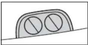 (Flash quickly) (Flash quickly) | Charging indicatorIndicates a malfunction in the charging system | →P. 59 |
 | Output control warning light (warning buzzer)EV system power available is low (due to the amount of charge remaining in the traction battery being low, or low temperature or high temperature) | Charge the vehicle. |
 | Seat belt reminder light (warning buzzer)*2Warns the driver/front passenger to fasten his/her seat belt. | Fasten the seat belt. |
  | Master warning lightA buzzer sounds and the warning light comes on and flashes to indicate that the master warning system has detected a malfunction.Tire pressure warning light | →P. 427 |
| When the light comes on: Low tire inflation pressure such asNatural causes (→P. 422)Flat tire (→P. 447) | Adjust the tire inflation pressure (including the spare tire) to the specified level.The light will turn off after a few minutes. In case the light does not turn off even if the tire inflation pressure is adjusted, have the system checked by your Toyota dealer. | |
| When the light comes on after blinking for 1 minute: Malfunction in the tire pressure warning system (→P. 423) | Have the system checked by your Toyota dealer. | |
*1: Open door warning buzzer
→P. 433
*2:Driver's and front passenger's seat belt warning buzzers
The driver's and front passenger's seat belt warning buzzers sound to alert the driver and front passenger that his or her seat belt is not fastened. The buzzer sounds intermittently for 10 seconds after the vehicle has reached a speed of 12 mph (20 km/h). Then, if the seat belt is still unfastened, the buzzer will sound at a different tone for 20 more seconds.
■SRS warning light
This warning light system monitors the airbag sensor assembly, front impact sensors, side impact sensors, driver's seat position sensor, driver's seat belt buckle switch, front passenger occupant classification system, "AIR BAG ON" indicator light, "AIR BAG OFF" indicator light, front passenger's seat belt buckle switch, seat belt pretensioner assemblies, airbags, interconnecting wiring and power sources. (→P. 154)
■ Front passenger detection sensor and passenger seat belt reminder
- If luggage is placed on the front passenger seat, the front passenger detection sensor may cause the warning light to flash, even if a passenger is not sitting in the seat.
- If a cushion is placed on the seat, the sensor may not detect a passenger, and the warning light may not operate properly.
Electric power steering system warning light (warning buzzer)
When the 12-volt battery charge becomes insufficient or the voltage temporarily drops, the electric power steering system warning light may come on and the warning buzzer may sound.
■The tire pressure warning light may turn on due to natural causes
The tire pressure warning light may turn on due to natural causes such as natural air leaks or tire inflation pressure changes caused by temperature. In this case, adjusting the tire inflation pressure will turn off the warning light (after a few minutes).
■If the tire pressure warning system is inoperative
The tire pressure warning system will be disabled in the following conditions:
(When the condition becomes normal, the system will work properly.)
- If tires not equipped with tire pressure warning valves and transmitters are used.
- If the ID code on the tire pressure warning valves and transmitters is not registered in the tire pressure warning computer.
- If the tire inflation pressure is 73 psi (500 kPa, 5.1 kgf/cm ^2 or bar) or higher.
The tire pressure warning system may be disabled in the following conditions:
(When the condition becomes normal, the system will work properly.)
- If electronic devices or facilities using similar radio wave frequencies are nearby.
- If a radio set at similar frequencies is in use in the vehicle.
- If a window tint that affects the radio wave signals is installed.
- If there is a lot of snow or ice on the vehicle, in particular around the wheels or wheel housings.
- If non-genuine Toyota wheels are used (Even if you use Toyota wheels, the tire pressure warning system may not work properly with some types of tires.)
- If tire chains are used.
- If a large metallic object which can interfere with signal reception is put in the luggage compartment.
If the tire pressure warning light frequently comes on after blinking for 1 minute
If the tire pressure warning light frequently comes on after blinking for 1 minute when the “POWER” switch is turned to ON mode, have it checked by your Toyota dealer.
■ Customization that can be configured at Toyota dealer
The vehicle speed linked seat belt reminder buzzer can be disabled.
(Customizable features →P. 500) However, Toyota recommends that the seat belt reminder buzzer be operational to alert the driver and front passenger that the seat belts are not fastened.

CAUTION
■When the electric power steering warning light comes on
The steering wheel may become extremely heavy.
If the steering wheel becomes heavier than usual when operating, hold firmly and operate using more force than usual.
■If the tire pressure warning light comes on
Be sure to observe the following precautions. Failure to do so could cause a loss of vehicle control and result in death or serious injury.
- Stop your vehicle in a safe place as soon as possible. Adjust the tire inflation pressure immediately.
- If the tire pressure warning light comes on even after tire inflation pressure adjustment, it is probable that you have a flat tire. Check the tires. If the tire is flat, temporarily repair it with liquid sealants and have the flat tire repaired or replaced by the nearest Toyota dealer as soon as possible.
● Avoid abrupt maneuvering and braking. If the vehicle tires deteriorate, you could lose control of the steering wheel or the brakes.
If a blowout or sudden air leakage should occur
The tire pressure warning system may not activate immediately.

CAUTION
■Maintenance of the tires
Each tire, including the spare (if provided), should be checked monthly when cold and inflated to the inflation pressure recommended by the vehicle manufacturer on the vehicle placard or tire inflation pressure label (tire and load information label). (If your vehicle has tires of a different size than the size indicated on the vehicle placard or tire inflation pressure label [tire and load information label], you should determine the proper tire inflation pressure for those tires.)
As an added safety feature, your vehicle has been equipped with a tire pressure monitoring system (TPMS-tire pressure warning system) that illuminates a low tire pressure telltale (tire pressure warning light) when one or more of your tires is significantly under-inflated. Accordingly, when the low tire pressure telltale (tire pressure warning light) illuminates, you should stop and check your tires as soon as possible, and inflate them to the proper pressure. Driving on a significantly under-inflated tire causes the tire to overheat and can lead to tire failure. Under-inflation also reduces fuel efficiency (for electric vehicles, traction battery efficiency) and tire tread life, and may affect the vehicle's handling and stopping ability.
Please note that the TPMS (tire pressure warning system) is not a substitute for proper tire maintenance, and it is the driver's responsibility to maintain correct tire pressure, even if under-inflation has not reached the level to trigger illumination of the TPMS low tire pressure telltale (tire pressure warning light).

CAUTION
Your vehicle has also been equipped with a TPMS (tire pressure warning system) malfunction indicator to indicate when the system is not operating properly. The TPMS (tire pressure warning system) malfunction indicator is combined with the low tire pressure telltale (tire pressure warning light). When the system detects a malfunction, the telltale will flash for approximately one minute and then remain continuously illuminated. This sequence will continue upon subsequent vehicle start-ups as long as the malfunction exists. When the malfunction indicator is illuminated, the system may not be able to detect or signal low tire pressure as intended.
TPMS (tire pressure warning system) malfunctions may occur for a variety of reasons, including the installation of replacement or alternate tires or wheels on the vehicle that prevent the TPMS (tire pressure warning system) from functioning properly. Always check the TPMS (tire pressure warning system) malfunction telltale after replacing one or more tires or wheels on your vehicle to ensure that the replacement or alternate tires and wheels allow the TPMS (tire pressure warning system) to continue to function properly.

NOTICE
■Precaution when installing a different tire
When a tire of a different specification or maker is installed, the tire pressure warning system may not operate properly.
5-2. Steps to take in an emergency
If a warning message is displayed
If a warning is shown on the multi-information display, stay calm and perform the following actions:
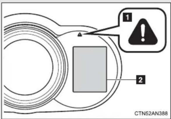
1 Master warning light
The master warning light also comes on or flashes in order to indicate that a message is currently being displayed on the multi-information display.
2 Multi-information display
If any of the warning lights turn on again after the following actions, contact your Toyota dealer.
Stop the vehicle immediately.
A buzzer sounds and a warning message is shown on the multi-information display. The following warnings indicate the possibility of damage to the vehicle that may lead to an accident. Immediately stop the vehicle in a safe place and contact your Toyota dealer.
| Warning message Details | |
 | Indicates a malfunction in the EV system. |
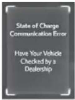 | Indicates a malfunction in the SOC gauge. |
 | |
Have the vehicle inspected immediately.
Failure to investigate the cause of the following warnings may lead to the system operating abnormally and possibly cause an accident. Have the vehicle inspected by your Toyota dealer immediately.
| Warning message Details | |
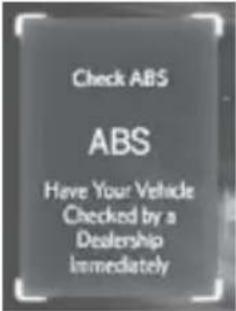 | Indicates a malfunction in:• The ABS; or,• The brake assist systemA buzzer also sounds. |
| ABS | |
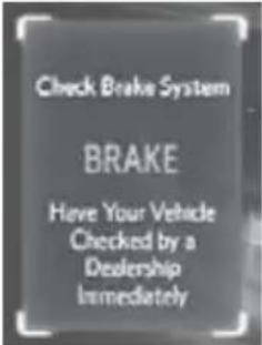 | Indicates a malfunction in:• Low brake fluid• The brake systemA buzzer also sounds. |
 | |
 | |
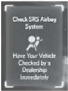 | Indicates a malfunction in:• The SRS airbag system;• The front passenger occupant classification system; or,• The seat belt pretensioner systemA buzzer also sounds. |
 | |
 | |
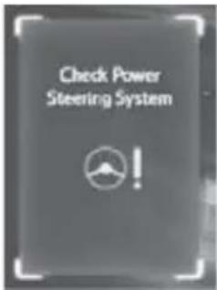 | Indicates a malfunction in the EPS (Electric Power Steering) system.A buzzer also sounds. |
 | |
 | |
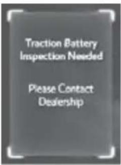 | Indicates a malfunction in the traction battery. |
 | |
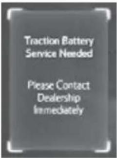 | |
 | |
 | Indicates a malfunction in the steering lock system.A buzzer also sounds. |
 | |
 | Indicates a malfunction in the cruise control system. Press the “ON-OFF” button once to deactivate the system, and then press the button again to reactivate the system.A buzzer also sounds. |
 | |
 (Flashes) (Flashes) | |
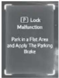 | Indicates a malfunction in the P position control sys-tem.In this situation, there is a possibility that the parking lock mechanism will not work.When parking, park the vehicle on a flat surface and apply the parking brake securely. Also, it may not be possible to turn the “POWER” switch off. If this hap-pens, applying the parking brake will enable the switch to be turned off.A buzzer also sounds. |
 | |
Follow the correction procedures.
A buzzer sounds and a warning message is shown on the multi-information display. After taking the specified steps to correct the suspected problem, check that the warning message goes off.
| Warning message Details Correction procedure | ||
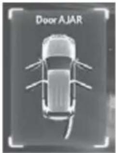 | Indicates that one or more of the doors or back door is not fully closed.The system also indicates which doors are not fully closed.If the vehicle reaches a speed of 3 mph (5 km/h),and a buzzer sounds to indicate that the door(s) are not yet fully closed. | Make sure that all the doors are closed.flashes |
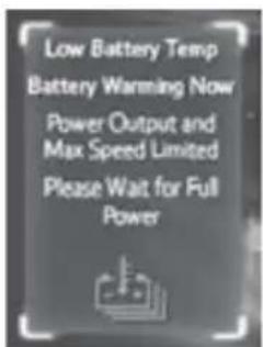 | Due to the traction battery's temperature being low, power output and maximum speed are limited. | Wait for battery warm-up to be completed. |
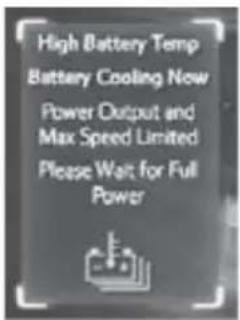  | Due to the traction battery's temperature being high, power output and maximum speed are limited. | Wait for battery cooling to be completed. |
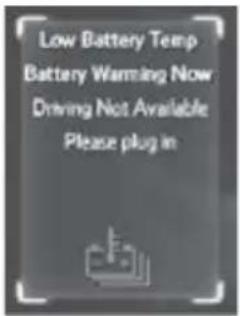  | The EV system was started while the traction battery's temperature was very low. | Plug in the vehicle to warm-up the battery. |
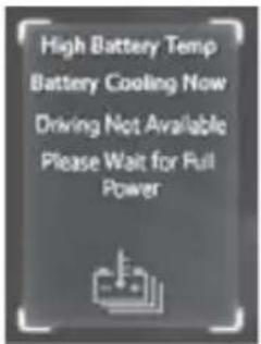  | The EV system was started while the traction battery's temperature is high. | Wait for the vehicle to cool down before driving. |
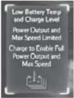 | Due to the amount of charge remaining in the traction battery and its temperature being low, power output and maximum speed are limited. | Charge the vehicle.(→P. 53)Wait for battery warm-up to be completed. |
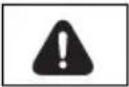 | ||
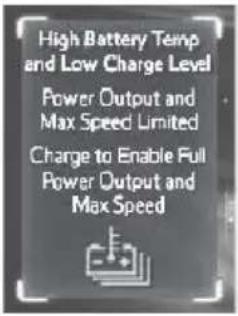 | Due to the traction battery's high temperature and the amount of charge remaining in the traction battery being low, power output and maximum speed are limited. | Charge the vehicle.(→P. 53)Wait for battery cooling to be completed. |
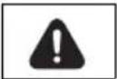 | ||
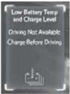 | The EV system was started while the traction battery's temperature and amount of charge remaining in the traction battery are low. | Charge the vehicle.(→P. 53)Wait for battery warm-up to be completed. |
 | ||
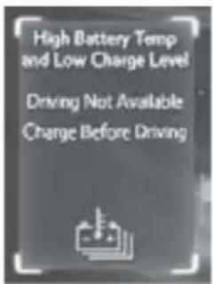  | The EV system was started while the traction battery's temperature is high and the amount of charge remaining in the traction battery is low. | Charge the vehicle. (→P. 53)Wait for battery cooling to be completed. |
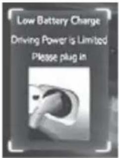  | Due to the amount of charge remaining in the traction battery being low, power output is limited. | Charge the vehicle. (→P. 53) |
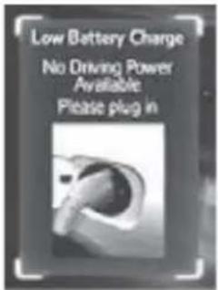  | The EV system was started while the amount of charge remaining in the traction battery is low. | Charge the vehicle immediately. (→P. 53) |
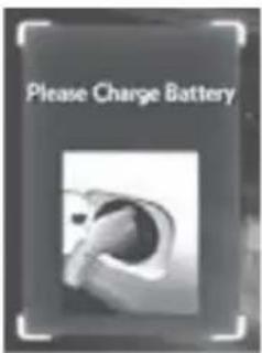 | The EV system was turned off while the amount of charge remaining in the traction battery is low. | Charge the vehicle.(→P. 53) |
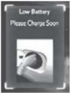 | The amount of charge remaining in the traction battery is low.A buzzer also sounds. | Charge the vehicle.(→P. 53) |
 | ||
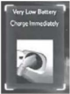 | The amount of charge remaining in the traction battery is low.A buzzer also sounds. | Charge the vehicle.(→P. 53) |
 | ||
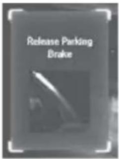 | Indicates that the parking brake is still engaged. flashes and a buzzer sounds to indicate that the parking brake is still engaged (with the vehicle having reached a speed of 3 mph [5 km/h]). flashes and a buzzer sounds to indicate that the parking brake is still engaged (with the vehicle having reached a speed of 3 mph [5 km/h]). | Release the parking brake. |
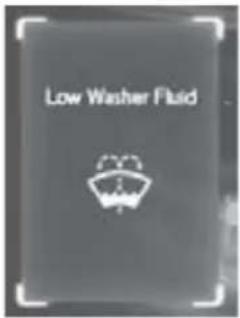 | Indicates that the washer fluid level is low. | Add washer fluid. |
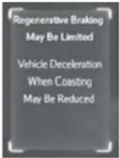 | Due to the amount of charge remaining in the traction battery being high, power regenerated through regenerative braking is reduced. | Apply the brake pedal as needed to slow down. |
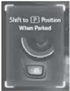  (Flashes) (Flashes) | The driver's door is opened when the transmission is out of P with the EV system on. | Push the P position switch. |
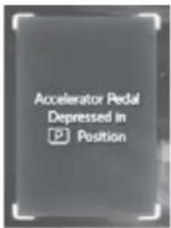  (Flashes) (Flashes) | Indicates that the accelerator pedal is depressed while the shift position is in P. A buzzer also sounds. | Release the accelerator pedal and shift the shift position to D or R. |
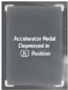  (Flashes) (Flashes) | Indicates that the accelerator pedal is depressed while the shift position is in N. A buzzer also sounds. | Release the accelerator pedal and shift the shift position to D or R. |
Have the malfunction repaired immediately.
After taking the specified steps to correct the suspected problem, check that the warning message and light turn off.
| Interior buzzer | Exterior buzzer | Warning message Details | Correction procedure | |
| Once — | 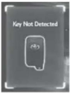 (Comes on for 10 seconds.) (Comes on for 10 seconds.) (Flashes) (Flashes) | The electronic key is not detected when attempting to start the EV system. | Confirm the location of the electronic key. | |
| Once 3 times | 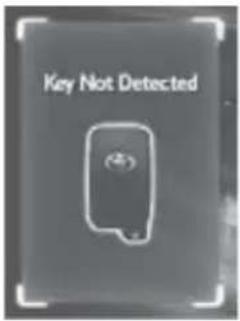  (Flashes) (Flashes) | An open door other than the driver's door is closed while the electronic key is outside the detection range and the "POWER" switch is in ACCESSORY or ON mode. | Confirm the location of the electronic key. | |
| Once 3 times | 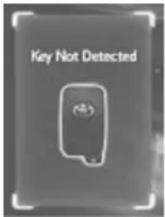 | Turn the “POWER” switch to off or confirm the location of the electronic key. | ||
 (Flashes) (Flashes) | ||||
| Continuous | — | 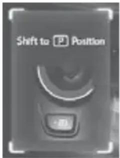 | The driver's door has been opened with the shift position in a position other than P and without first turning the “POWER” switch off. | |
 (Flashes) (Flashes) | ||||
| Once — | 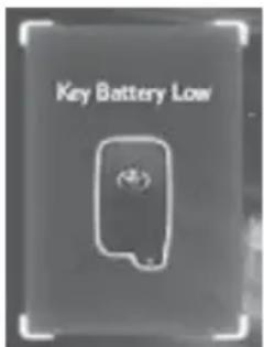 | The electronic key battery is low. | ||
 | ||||
| Once — | 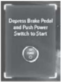  (Flashes) (Flashes) | An open door has been closed and the “POWER” switch has been turned twice to the ACCES- SORY mode from off. | Press the “POWER” switch while depress- ing the brake pedal. | |
| — | — | 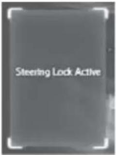  (Flashes) (Flashes) | Indicates that the steering lock has not released within 3 seconds of pressing the “POWER” switch. | Press the “POWER” switch again while turning the steering wheel with the brake pedal depressed. |
Charging and pre-climate messages
Charging messages are shown on the multi-information display when: the traction battery is being charged using the charging cable, the driver's door is opened, and the "POWER" switch is turned to ON mode after charging has been completed (when both charging indicator lights illuminate).
If one of the messages is displayed, follow the correction procedures.
| Messages Details | Correction procedure | |
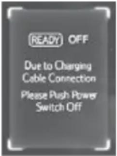 | The charging cable has been connected to the vehicle while the “READY” indicator light was illuminated.A buzzer also sounds. | A safety function* operates and automatically turns off the EV system.Turn the “POWER” switch off, and perform charging according to the instructions on page 91. |
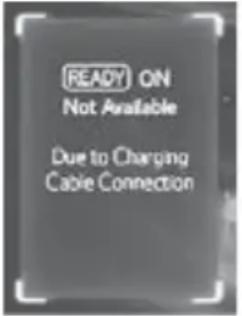 | An attempt has been made to start the EV system while the charging cable was connected.A buzzer also sounds. | A safety function* operates, not allowing the EV system to be started while the charging cable is connected.Remove the charging cable and start the EV system. |
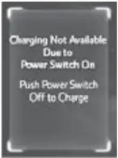 | An attempt to start charging while the “POWER” switch is in ON mode was made. | Charging has not been properly completed.Perform charging again according to the instructions on page 53.The vehicle can be driven without performing charging again, however, the drivable distance will be shortened. |
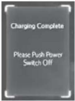 | Charging has been completed and the “POWER” switch was turned to ON mode.• The message will be displayed even if charging was interrupted by a power outage, the charging cable being disconnected, etc.• This message will be displayed in conjunction with other messages. The simultaneously displayed message will differ in accordance with the charging status (for example, if charging was completed or has been interrupted). | Turn the “POWER” switch off once and the display will turn off. Then turn the “POWER” switch to ON mode.• If a message warning of an interruption in charging is displayed simultaneously, turn the “POWER” switch off. After approximately 6 seconds have passed, turn the “POWER” switch back to ON mode.• After the “POWER” switch operations have been performed, the vehicle can be driven as normal. |
 | Charging was aborted due to a reduction in power from the power source. | Charging has not been properly completed. Perform charging again according to the instructions on page 53. The vehicle can be driven without performing charging again, however, the drivable distance will be shortened. |
 | The charging cable was disconnected from the vehicle during charging. | Charging has not been properly completed.Perform charging again according to the instructions on page 53.The vehicle can be driven without performing charging again, however, the drivable distance will be shortened. |
 | One of the following has occurred during charging:• The charging cable was disconnected.• Charging was interrupted by a power outage or similar. | Charging has not been properly completed.Perform charging again according to the instructions on page 53.The vehicle can be driven without performing charging again, however, the drivable distance will be shortened. |
 | Charging was aborted due to a system malfunction. | Contact your Toyota dealer. |
 | Charging was aborted due to high consumption of the 12-volt battery. | Perform charging again after turning off electrical components that use the 12-volt battery, such as the audio system and air conditioning system. |
 | Charging was aborted due to low traction bat-tery temperature. | Wait for battery warm-up to be completed. |
 | Pre-climate operations were aborted due to the amount of charge remaining in the traction battery being low. | Charge the vehicle.(→P. 53) |
 | Pre-climate operations were aborted due to a door being opened. | Reset the pre-climate settings or restart oper-ations using a smart phone. (→P. 57, 58) |
* For more information regarding safety systems, see page 88.
■ Charging Message Details
Depending on operation conditions, the details of a message shown on the multi-information display and actual vehicle conditions may differ (for example the previous condition may be shown). However, the following are not a malfunction:
If “Charging Not Available Due to IG On turn IG Off to Charge” is shown on the multi-information display, the message may still be displayed even after the “POWER” switch is turned off once, the charging cable is reconnected and the “POWER” switch is turned to ON mode again. However, if the charging indicator lights are illuminated or flashing ( P. 63), charging has recommenced correctly.
If “Canceled” is shown on the multi-information display, pre-climate operations stopped partway through due to the system judging that 15 minutes of pre-climate operations was unnecessary. For example, soon after pre-climate operations started, the cabin temperature reached the set temperature and pre-climate operations were stopped early.
When pre-climate has completed operations normally, “Complete” is shown on the multi-information display.
A puncture caused by a nail or screw passing through the tire tread can be repaired temporarily using the emergency tire puncture repair kit. (The kit contains a bottle of sealant. The sealant can be used only once to temporarily repair one tire without removing the nail or screw from the tire.) Depending on the damage, this kit cannot be used to repair the tire. ( P. 450)
After temporarily repairing the tire with the kit, have the tire repaired or replaced by your Toyota dealer. Repairs conducted using the emergency tire puncture repair kit are only a temporary measure. Have the tire repaired and replaced as soon as possible.
■ Before repairing the tire
- Stop the vehicle in a safe place on a hard, flat surface.
- Set the parking brake.
●Push the P position switch. - Stop the EV system.
●Turn on the emergency flashers.
■ Location of the emergency tire puncture repair kit
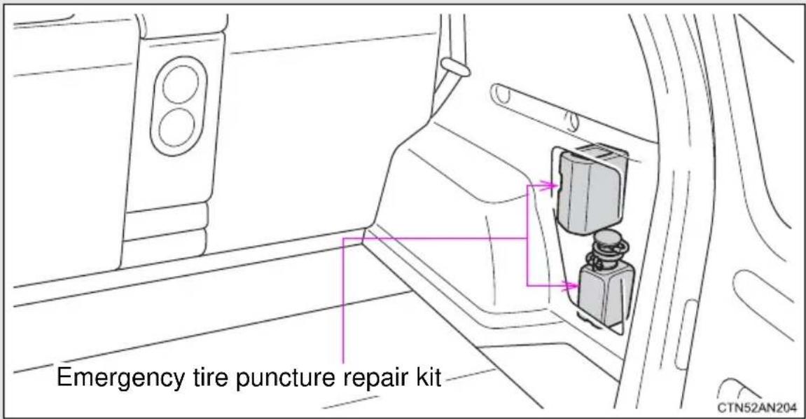
Emergency tire puncture repair kit components
Bottle
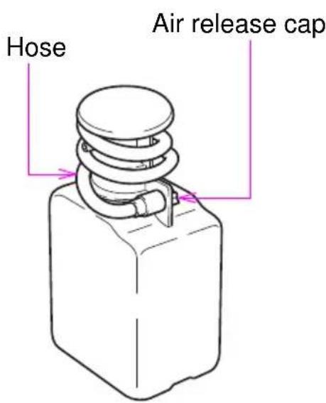
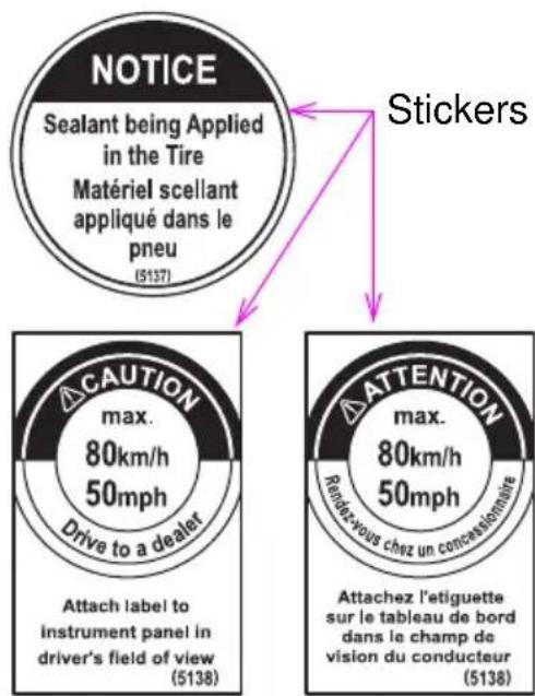
Before performing emergency repair
Check the degree of the tire damage.
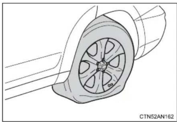
natural_image
Technical line drawing of a car wheel assembly (no text or symbols)A tire should only be repaired with the emergency tire puncture repair kit if the damage is caused by a nail or screw passing through the tire tread.
- Do not remove the nail or screw from the tire. Removing the object may widen the opening and prevent emergency repair with the repair kit.
- To avoid sealant leakage, move the vehicle until the area of the puncture, if known, is positioned at the top of the tire.
In the following cases, the tire cannot be repaired with the emergency tire puncture repair kit. Contact your Toyota dealer.
- When the tire is damaged due to driving without sufficient air pressure
- When there are any cracks or damage at any location on the tire except the tread, such as the sidewall
- When the tire is visibly separated from the wheel
- When the cut or damage to the tread is 0.16 in. (4 mm) long or more
- When the wheel is damaged
- When two or more tires have been punctured
- When 2 or more sharp objects, such as nails or screws, have passed through the tread on a single tire
- When the sealant has expired
Taking out the emergency tire puncture repair kit
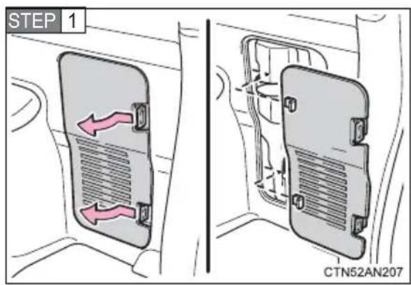
Disengage the claws and remove the cover.
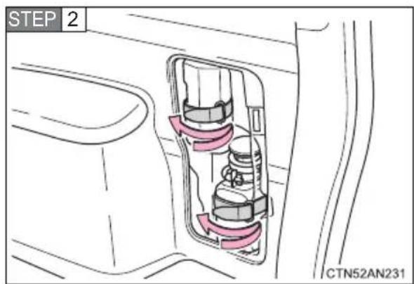
Take out the emergency tire puncture repair kit.
Emergency repair method
STEP 1 Take out the repair kit from the luggage compartment.
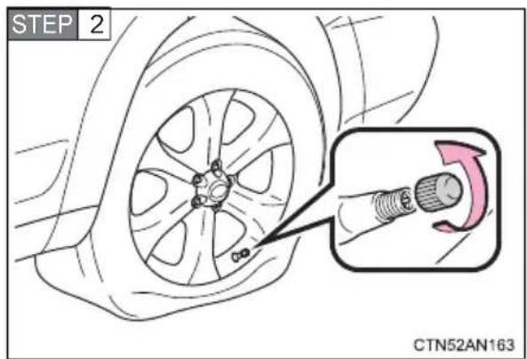
Remove the valve cap from the valve of the punctured tire.
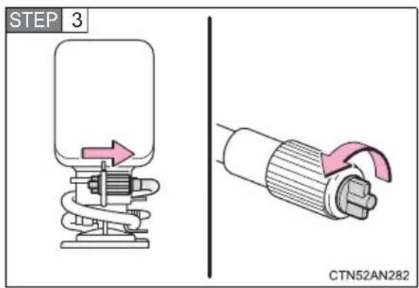
Extend the hose. Remove the air release cap from the hose.
You will use the air release cap again. Therefore, keep it in a safe place.
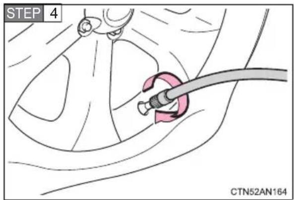
Connect the hose to the valve.
Screw the end of the hose clockwise as far as possible.
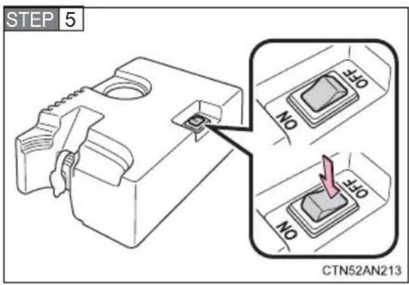
Make sure that the compressor switch is off.
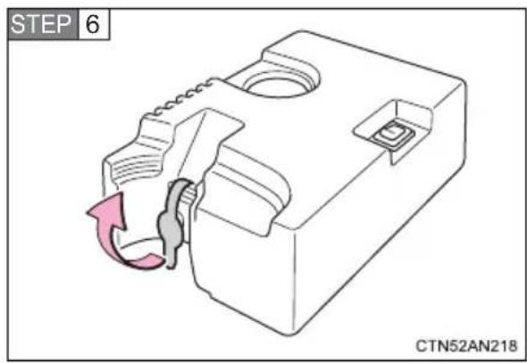
Lift the rubber stopper on the compressor.
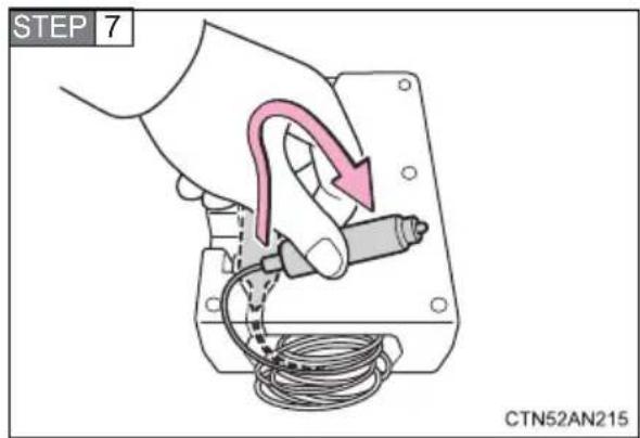
Remove the power plug from the compressor.
STEP 8 Connect the power plug to the power outlet socket. (→P. 306)
Type A
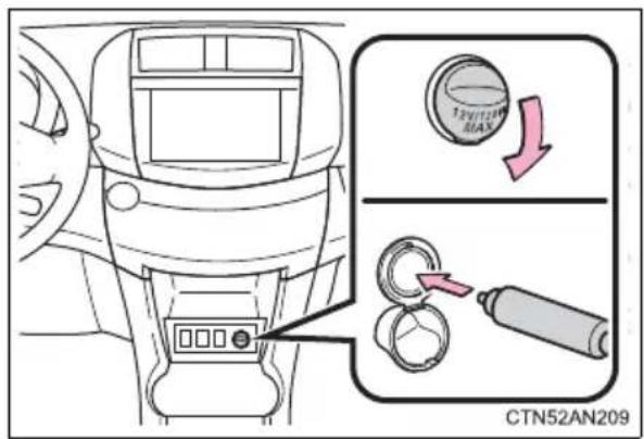
Type B
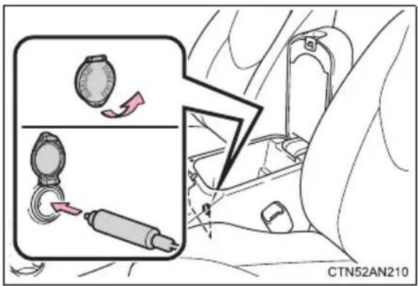
Type C
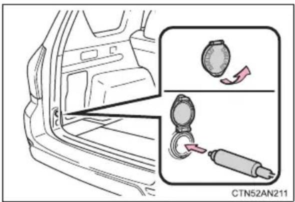
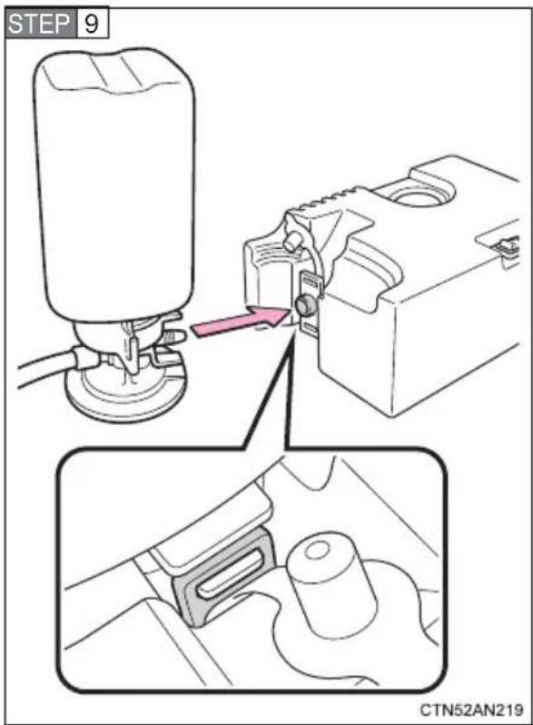
Connect the bottle to the compressor.
Make sure that the bottle is securely connected.
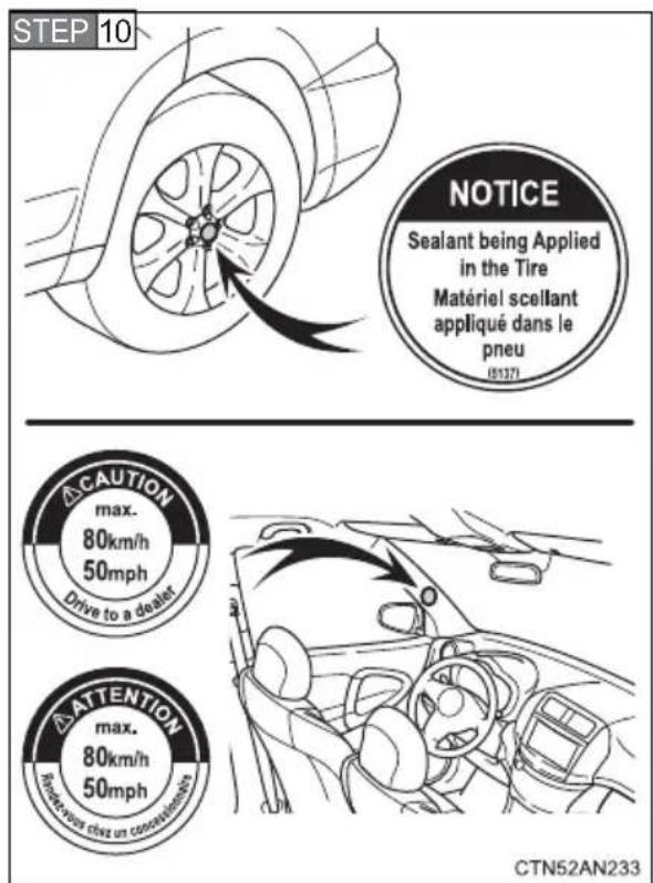
Attach the 2 stickers as shown.
Remove any dirt and moisture from the wheel before attaching the label. If it is impossible to attach the label, make sure to tell your Toyota dealer when you have them repair and replace the tire that sealant is injected.
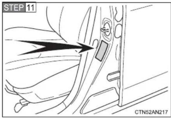
STEP 12 Start the EV system.
Check the specified tire inflation pressure.
Tire inflation pressure is specified on the label on the driver's side pillar as shown. (→P. 488)
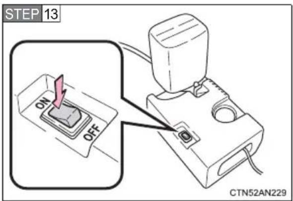
To inject the sealant and inflate the tire, turn the compressor switch on.
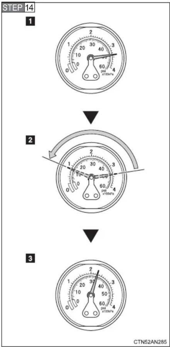
Inflate the tire until the specified air pressure is reached.
1 The sealant will be injected and the pressure will spike to 44 psi (300 kPa, 3.1 kgf/cm² or bar) to 58 psi (400 kPa, 4.1 kgf/cm² or bar), and then gradually decrease.
2 The air pressure gauge will display the actual tire inflation pressure about 1 minute (15 minutes at low temperature) after the switch is turned on.
3 Inflate the tire until the specified air pressure.
- Turn the compressor switch off and then check the tire inflation pressure. Being careful not to over inflate, check and repeat the inflation procedure until the specified tire inflation pressure is reached.
- If the tire inflation pressure is still lower than the specified point after inflation for 10 minutes (35 minutes at low temperature) with the switch on, the tire is too damaged to be repaired. Turn the compressor switch off and contact your Toyota dealer.
- If the tire inflation pressure exceeds the specified air pressure, let out some air to adjust the tire inflation pressure. (→P. 460, 488)
STEP 15 With the compressor switch off, disconnect the hose from the valve on the tire and then pull out the power plug from the power outlet socket.
Some sealant may leak when the hose is removed.
STEP 16 Install the valve cap onto the valve of the emergency repaired tire.
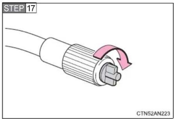
Attach the air release cap to the end of the hose.
If the air release cap is not attached, the sealant may leak and the vehicle may get dirty.
Do not insert sharp objects into the tip of the bottle's hose.
STEP 18 Temporarily store the bottle in the luggage compartment while it is connected to the compressor.
STEP 19 To spread the liquid sealant evenly within the tire, immediately drive safely for about 3 miles (5 km) below 50 mph (80 km/h).
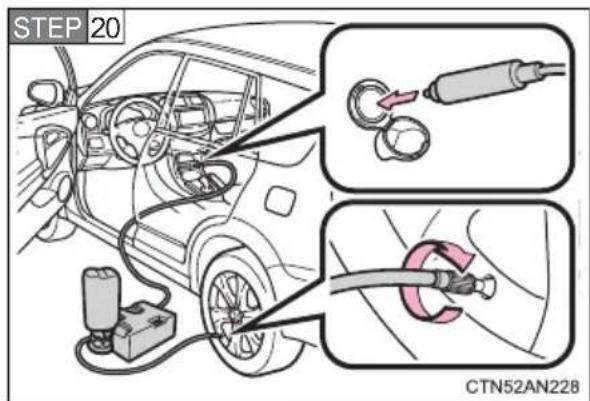
After driving for about 3 miles (5 km), stop your vehicle in a safe place on a hard, flat surface and remove the air release cap from the hose before reconnecting the repair kit.
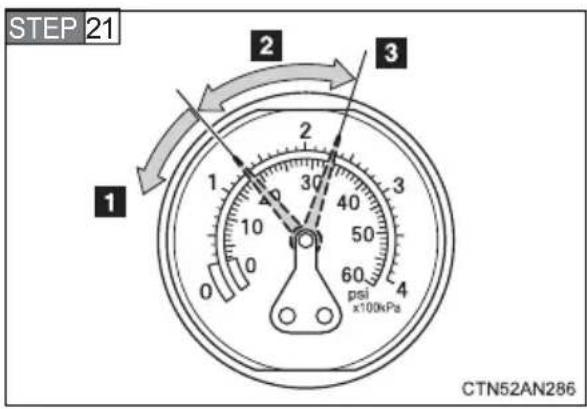
Turn the compressor switch on and wait for an approximately 5 seconds, and then turn it off. Check the tire inflation pressure.
1 If the tire inflation pressure is under 19 psi (130 kPa, 1.3 kgf/cm ^2 or bar): The puncture cannot be repaired. Contact your Toyota dealer.
2 If the tire inflation pressure is 19 psi (130 kPa, 1.3 kgf/cm² or bar) or higher, but less than the specified air pressure: Proceed to STEP 22
3 If the tire inflation pressure is the specified air pressure (→P. 488): Proceed to STEP 23
STEP 22 Turn the compressor switch on to inflate the tire until the specified air pressure is reached. Drive for about 3 miles (5 km) and then perform STEP 20
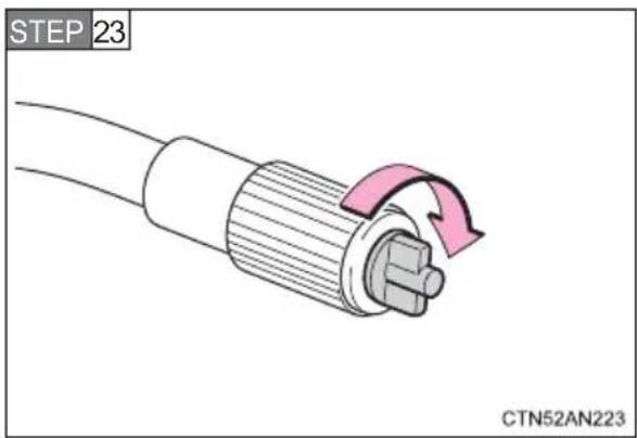
Attach the air release cap to the end of the hose.
If the air release cap is not attached, the sealant may leak and the vehicle may get dirty.
Do not insert sharp objects into the tip of the bottle's hose.
STEP 24 Store the bottle in the luggage compartment while it is connected to the compressor.
STEP 25 Taking precautions to avoid sudden braking, sudden acceleration and sharp turns, drive carefully at under 50 mph (80 km/h) to a Toyota dealer that is less than 62 miles (100 km) away for tire repair or replacement.
If the tire is inflated to more than the specified air pressure
STEP 1 Disconnect the hose from the valve.
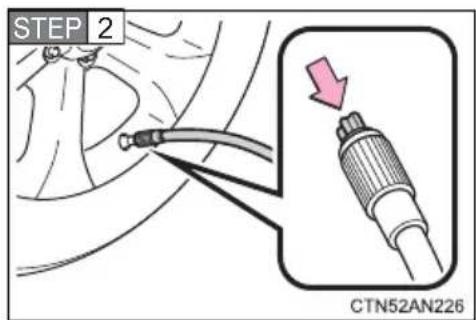
Install the air release cap to the end of the hose and push the protrusion on the air release cap into the tire valve to let some air out.
STEP 3 Disconnect the hose from the valve, remove the air release cap from the hose and then reconnect the hose.
STEP 4 Turn the compressor switch on and wait for several seconds, and then turn it off. Check that the air pressure indicator shows the specified air pressure.
If the air pressure is under the designated pressure, turn the compressor switch on again and repeat the inflation procedure until the specified air pressure is reached.
■The valve of a tire that has been repaired
After a tire is repaired with the emergency tire puncture repair kit, the valve should be replaced.
■Note for checking the emergency tire puncture repair kit
Check the sealant expiration date occasionally.
The expiration date is shown on the bottle. Do not use sealant whose expiration date has already passed. Otherwise, repairs conducted using the emergency tire puncture repair kit may not be performed properly.
Emergency tire puncture repair kit
●The sealant stored in the emergency tire puncture repair kit can be used only once to temporarily repair a single tire. If the sealant has been used and needs to be replaced, purchase a new bottle at your Toyota dealer. The compressor is reusable.
●The sealant can be used when the outside temperature is from -40^ ( -40^ ) to 140^ ( 60^ ).
●The repair kit is exclusively designed for the size and type of tires originally installed on your vehicle. Do not use it for tires that are a different size than the original ones, or for any other purposes.
●The sealant has a limited lifespan. The expiration date is marked on the bottle. The bottle of sealant should be replaced with a new bottle before the expiration date. Contact your Toyota dealer for replacement.
- If the sealant gets on your clothes, it may stain.
- If the sealant adheres to a wheel or the surface of the vehicle body, the stain may not be removable if it is not cleaned at once. Immediately wipe away the sealant with a wet cloth.
● During operation of the repair kit, a loud operation noise is produced. This does not indicate a malfunction.
- Do not use to check or to adjust the tire pressure.

CAUTION
■Do not drive the vehicle with a flat tire
Do not continue driving with a flat tire.
Driving even a short distance with a flat tire can damage the tire and the wheel beyond repair.
Driving with a flat tire may cause a circumferential groove on the side wall. In such a case, the tire may explode when using a repair kit.
■Caution while driving
●Store the repair kit in the luggage compartment.
Injuries may result in the event of an accident or sudden braking.
●The repair kit is exclusively only for your vehicle.
Do not use repair kit on other vehicles, which could lead to an accident causing death or serious injury.
- Do not use repair kit for tires that are different size than the original ones, or for any other purpose. If the tires have not been completely repaired, it could lead to an accident causing death or serious injury.
■Precautions for use of the sealant
- Ingesting the sealant is hazardous to your health. If you ingest sealant, consume as much water as possible, and then immediately consult a doctor.
- If sealant gets in eyes or adheres to skin, immediately wash it off with water. If discomfort persists, consult a doctor.
■When fixing the flat tire
- Stop your vehicle in a safe and flat area.
- Do not touch the wheels or the area around the brakes immediately after the vehicle has been driven.
After the vehicle has been driven, the wheels and the area around the brakes may be extremely hot. Touching these areas with hands, feet or other body parts may result in burns. - Connect the valve and hose securely with the tire installed on the vehicle. If the hose is not properly connected to the valve, air leakage may occur as sealant may be sprayed out.
- If the hose comes off the valve while inflating the tire, there is a risk that the hose will move abruptly due to air pressure.

CAUTION
● After inflation of the tire has completed, the sealant may splatter when the hose is disconnected or some air is let out of the tire.
●Follow the operation procedure to repair the tire. If the procedures not followed, the sealant may spray out.
- Keep back from the tire while it is being repaired, as there is a chance of it bursting while the repair operation is being performed. If you notice any cracks or deformation of the tire, turn off the compressor switch and stop the repair operation immediately.
●The repair kit may overheat if operated for a long period of time. Do not operate the repair kit continuously for more than 35 minutes.
●Parts of the repair kit become hot during operation. Be careful when handling the repair kit during and after operation. Do not touch the metal part around the connecting area between the bottle and compressor. It will be extremely hot.
- Do not attach the vehicle speed warning sticker to an area other than the one indicated. If the sticker is attached to an area where an SRS airbag is located, such as the pad of the steering wheel, it may prevent the SRS airbag from operating properly.
■Driving to spread the liquid sealant evenly
Observe the following precautions to reduce the risk of accidents.
Failing to do so may result in a loss of vehicle control and cause death or serious injury.
● Drive the vehicle carefully at a low speed. Be especially careful when turning and cornering.
- If the vehicle does not drive straight or you feel a pull through the steering wheel, stop the vehicle and check the following.
- Tire condition. The tire may have separated from the wheel.
- Tire inflation pressure. If the tire inflation pressure is 19 psi (130 kPa, 1.3 ~kgf / cm^2 or bar) or less, the tire may be severely damaged.

NOTICE
■When performing an emergency repair
● A tire should only be repaired with the emergency tire puncture repair kit if the damage is caused by a sharp object such as a nail or screw passing through the tire tread.
Do not remove the sharp object from the tire. Removing the object may widen the opening and disenable emergency repair with the repair kit.
●The repair kit is not waterproof. Make sure that the repair kit is not exposed to water, such as when it is being used in the rain.
- Do not put the repair kit directly onto dusty ground such as sand at the side of the road. If the repair kit vacuums up dust etc., a malfunction may occur.
■Precautions for the emergency tire puncture repair kit
●The repair kit power source should be 12 V DC suitable for vehicle use. Do not connect the repair kit to any other source.
- If gasoline splatters on the repair kit, the repair kit may deteriorate. Take care not to allow gasoline to contact it.
- Place the repair kit in the specified storage location to prevent it from being exposed to dirt or water.
- Store the repair kit out of reach of children.
- Do not disassemble or modify the repair kit. Do not subject parts such as the air pressure indicator to impacts. This may cause a malfunction.
Reasons for the EV system not starting vary depending on the situation. Check the following and perform the appropriate procedure:
The EV system will not start even though the correct starting procedure is being followed. (→P. 200)
One of the following may be the cause of the problem:
●The charging cable may be connected to the vehicle.
● The electronic key may not be functioning properly. (→P. 468)
●There may be a malfunction in the immobilizer system. (→P. 149)
●There may be a malfunction in the steering lock system.
- The EV system may be malfunctioning due to an electrical problem such as an open circuit or a blown fuse. However, depending on the type of malfunction, an interim measure is available to start the EV system. (→P. 385)
- There may be a malfunction in the P position control system.* (→P. 203)
*: It may not be possible to shift the shift position from P to other positions.
The interior lights and headlights are dim, or the horn does not sound or sounds at a low volume.
One of the following may be the cause of the problem:
● The 12-volt battery may be discharged. (→P. 470)
● The 12-volt battery terminal connections may be loose or corroded.
The interior lights and headlights do not turn on, or the horn does not sound.
One of the following may be the cause of the problem:
● One or both of the 12-volt battery terminals may be disconnected.
● The 12-volt battery may be discharged. (→P. 470)
Contact your Toyota dealer if the problem cannot be repaired, or if repair procedures are unknown.
Emergency start function
When the EV system does not start, the following steps can be used as an interim measure to start the EV system if the “POWER” switch is functioning normally.
STEP 1 Set the parking brake.
STEP 2 Set the "POWER" switch to the ACCESSORY mode.
STEP 3 Push and hold the "POWER" switch for about 15 seconds while depressing the brake pedal firmly.
Even if the EV system can be started using the above steps, the system may be malfunctioning. Have the vehicle checked by your Toyota dealer.
5-2. Steps to take in an emergency
If you lose your keys
New genuine Toyota keys can be made by your Toyota dealer using the other key and the key number stamped on your key number plate.
5-2. Steps to take in an emergency
If the electronic key does not operate properly
If communication between the electronic key and vehicle is interrupted ( P. 104) or the electronic key cannot be used because the battery is depleted, the smart key system and wireless remote control cannot be used. In such cases, the doors and back door can be opened and the EV system can be started by following the procedure below.
Locking and unlocking the doors with the mechanical key
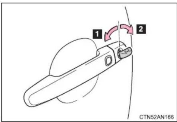
Use the mechanical key ( P. 94) in order to perform the following operations:
1 Locks all the doors
2 Unlocks all the doors
Turning the key rearward unlocks the driver's door. Turning the key once again unlocks the other doors.
Changing "POWER" switch modes and starting the EV system
STEP 1 Apply the brakes.
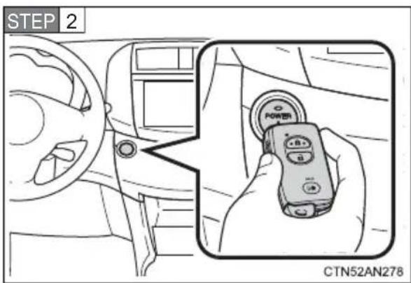
Touch the Toyota emblem side of the electronic key to the "POWER" switch.
If any of the doors is opened and closed while the key is being touched to the switch, an alarm will sound to indicate that the start function cannot detect the electronic key.
STEP 3 To change "POWER" switch modes:
Within 10 seconds of the buzzer sounding, release the brake pedal and press the “POWER” switch. Modes can be changed each time the switch is pressed. ( P. 202)
To start the EV system:
Press the “POWER” switch within 10 seconds of the buzzer sounding, keeping the brake pedal depressed.
In the event that the EV system still cannot be operated, contact your Toyota dealer.
■Stopping the EV system
Set the parking brake, push the P position switch and press the "POWER" switch as you normally do when stopping the EV system.
■Replacing the key battery
As the above procedure is a temporary measure, it is recommended that the electronic key battery be replaced immediately when the battery is depleted. ( P. 383)
5-2. Steps to take in an emergency
If the vehicle 12-volt battery is discharged
The following procedures may be used to start the EV system if the vehicle's 12-volt battery is discharged.
You can also call your Toyota dealer or a qualified repair shop.
If you have a set of jumper (or booster) cables and a second vehicle with a 12-volt battery, you can jump start your vehicle following the steps below.
STEP 1 Open the hood.
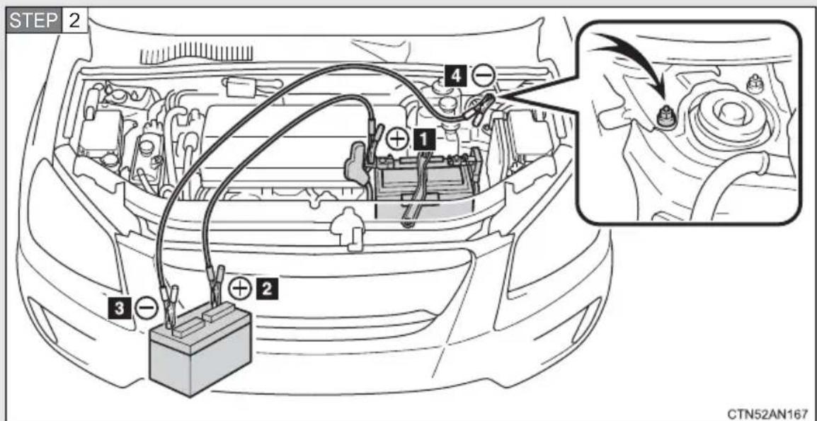
Connect the jumper cables according to the following procedure:
1 Connect a positive jumper cable clamp to the positive (+) battery terminal on your vehicle.
2 Connect the clamp on the other end of the positive cable to the positive (+) battery terminal on the second vehicle.
3 Connect a negative cable clamp to the negative (-) battery terminal on the second vehicle.
4 Connect the clamp at the other end of the negative cable to a solid, stationary, unpainted metallic point away from the battery and any moving parts as shown in the illustration.
STEP 3 Start the engine of the second vehicle. Increase the engine speed slightly and maintain that level for approximately 5 minutes to recharge the 12-volt battery of your vehicle.
STEP 4 Open and close any of the doors of your vehicle with the "POWER" switch off.
STEP 5 Maintain the engine speed of the second vehicle and start the EV system of your vehicle by turning the "POWER" switch to ON mode.
STEP 6 Make sure the "READY" indicator comes on. If the indicator does not come on, contact your Toyota dealer.
STEP 7 Once the EV system has started, remove the jumper cables in the exact reverse order from which they were connected.
Once the EV system starts, have the vehicle inspected at your Toyota dealer as soon as possible.
■ Starting the EV system when the 12-volt battery is discharged
The EV system cannot be started by push-starting.
■To prevent 12-volt battery discharge
●Turn off the headlights and the navigation system while the EV system is off.
●Turn off any unnecessary electrical components when the vehicle is running at a low speed for an extended period, such as in heavy traffic.
■When the 12-volt battery is removed or discharged
● The EV system may not start. (→P. 363)
- If the 12-volt battery discharges while the shift position is in P, it may not be possible to shift the shift position to other positions.
In this case, the vehicle cannot be moved without lifting both front wheels because the front wheels will be locked. (→P. 413)
● The power windows must be initialized. (→P. 147)
Charging the 12-volt battery
The electricity stored in the 12-volt battery will discharge gradually even when the vehicle is not in use, due to natural discharge and the draining effects of certain electrical appliances. If the vehicle is left for a long time, the 12-volt battery may discharge, and the EV system may be unable to start. (The 12-volt battery recharges automatically while the EV system is operating.)

CAUTION
■Avoiding 12-volt battery fires or explosions
Observe the following precautions to prevent accidentally igniting the flammable gas that may be emitted from the 12-volt battery:
● Make sure each jumper cable is connected to the correct terminal and that it is not unintentionally in contact with any other than the intended terminal.
- Do not allow the other end of the jumper cable connected to the “+” terminal to come into contact with any other parts or metal surfaces in the area, such as brackets or unpainted metal.
- Do not allow the + and - clamps of the jumper cables to come into contact with each other.
- Do not smoke, use matches, cigarette lighters or allow open flame near the 12-volt battery.
■12-volt battery precautions
The 12-volt battery contains poisonous and corrosive acidic electrolyte, while related parts contain lead and lead compounds. Observe the following precautions when handling the 12-volt battery:
- When working with the 12-volt battery, always wear safety glasses and take care not to allow any 12-volt battery fluids (acid) to come into contact with skin, clothing or the vehicle body.
- Do not lean over the 12-volt battery.
In the event that battery fluid comes into contact with the skin or eyes, immediately wash the affected area with water and seek medical attention. Place a wet sponge or cloth over the affected area until medical attention can be received.
● Always wash your hands after handling the 12-volt battery support, terminals, and other battery-related parts. - Do not allow children near the 12-volt battery.

NOTICE
■When handling jumper cables
When connecting the jumper cables, ensure that they do not become entangled in the cooling fans or belt.
If “High Battery Temp” is shown on the multi-information display, the vehicle may be overheating.
If the message does not disappear after driving for a little while, follow the correction procedure as described below.
Correction procedures
STEP 1 Stop the vehicle in a safe place and turn off the air conditioning system.
STEP 2 Check to see if steam is coming out from under the hood.
If you see steam:
Stop the EV system. Carefully lift the hood after the steam subsides and then restart the EV system.
If you do not see steam:
Leave the EV system operating and carefully lift the hood.
STEP 3 Check to see if the cooling fans are operating.
If the fans are operating:
Wait until "High Battery Temp" disappears and then stop the EV system.
If the fans are not operating:
Stop the EV system immediately and contact your Toyota dealer.
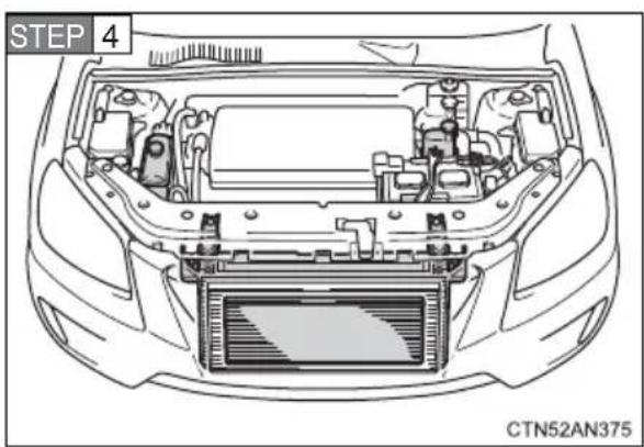
natural_image
Top-down technical drawing of a car headstock showing internal components and engine compartment (no text or symbols)After "High Battery Temp" disappears, check the motor/traction battery coolant level and inspect the cooling system for leaks.
There are 2 powertrain coolant reservoirs. Make sure to check both of them. ( P. 357)
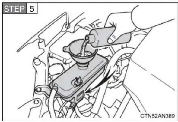
If necessary, add motor coolant up to the "FULL" line.
Add after confirming the type of coolant. (→P. 357)
Water can be used in an emergency if motor coolant is unavailable.
Have the vehicle checked at nearest Toyota dealer as soon as possible.

CAUTION
■ To prevent an accident or injury when inspecting under the hood of your vehicle
- If steam is seen coming from under the hood, do not open the hood until the steam has subsided. The motor compartment may be very hot, causing serious injury such as burns.
- Check that the indicator on the "POWER" switch and the "READY" indicator are off.
- When the "READY" indicator is illuminated, the cooling fans may suddenly start to operate. Do not touch or approach the fans. Doing so may lead to fingers, clothes or tools getting caught, resulting in an accidental injury.
- Do not loosen the coolant reservoir cap while the EV system and radiator are hot.
Serious injury, such as burns, may result from hot coolant and steam released under pressure.

NOTICE
■When adding motor coolant
Wait until the EV system has cooled down before adding motor coolant. When adding coolant, do so slowly. Adding cool coolant to a hot EV system too quickly can cause damage to the EV system.
Carry out the following procedures if the tires spin or the vehicle becomes stuck in mud, dirt or snow:
STEP 1 Set the parking brake, change the shift position to P and stop the EV system.
STEP 2 Remove the mud, snow or sand from around the front wheels.
STEP 3 Place wood, stones or some other material under the front wheels to help provide traction.
STEP 4 Restart the EV system.
STEP 5 Make sure to change the shift position to D or R, release the parking brake, and then carefully apply the accelerator to free the vehicle.
■When it is difficult to free the vehicle
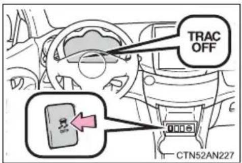
Press the VSC OFF switch to turn off TRAC.

CAUTION
■When attempting to free a stuck vehicle
If you choose to push the vehicle back and forth to free it, make sure the surrounding area is clear to avoid striking other vehicles, objects or people. The vehicle may also lunge forward or lunge back suddenly as it becomes free. Use extreme caution.
■When changing the shift position
Be careful not to change the shift position with the accelerator pedal depressed.
This may lead to unexpected rapid acceleration of the vehicle that may cause an accident resulting in death or serious injury.

NOTICE
■To avoid damage to the transmission and other components
● Avoid spinning the wheels and depressing the accelerator pedal more than necessary.
- If the vehicle remains stuck even after these procedures are performed, the vehicle may require towing to be freed.
5-2. Steps to take in an emergency
If your vehicle has to be stopped in an emergency
Only in an emergency, such as if it becomes impossible to stop the vehicle in the normal way, stop the vehicle using the following procedure:
STEP 1 Steadily step on the brake pedal with both feet and firmly depress it.
Do not pump the brake pedal repeatedly as this will increase the effort required to slow the vehicle.
STEP 2 Shift the shift position to N.
If the shift position is changed to N
STEP 3 After slowing down, stop the vehicle in a safe place by the road.
STEP 4 Stop the EV system.
If the shift position cannot be changed to N
STEP 3 Keep depressing the brake pedal with both feet to reduce vehicle speed as much as possible.
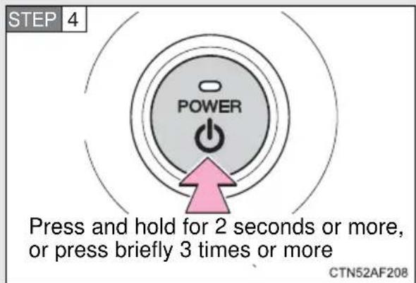
To stop the EV system, press and hold the "POWER" switch for 2 consecutive seconds or more, or press it briefly 3 times or more in succession.
STEP 5 Stop the vehicle in a safe place by the road.

CAUTION
If the EV system has to be turned off while driving
Power assist for the brakes and steering wheel will be lost, making the brake pedal harder to depress and the steering wheel heavier to turn. Decelerate as much as possible before turning off the EV system.
5-2. Steps to take in an emergency
Vehicle specifications
6
6-1. Specifications
Maintenance data (fluid capacity, etc.)..... 482 Tire information..... 489
6-2. Customization
Customizable features ..... 500
6-3. Initialization
Items to initialize 503
Dimensions and weights
| Overall length 180.1 in. (4575 mm) | |
| Overall width 71.5 in. (1815 mm) | |
| Overall height* 66.3 in. (1685 mm) | |
| Wheelbase 104.7 in. (2660 mm) | |
| Front tread 61.4 in. (1560 mm) | |
| Rear tread 61.4 in. (1560 mm) | |
| Vehicle capacity weight (Occupants + luggage) | 880 lb. (395 kg) |
*: Unladen vehicle
Vehicle identification
■Vehicle identification number
The vehicle identification number (VIN) is the legal identifier for your vehicle. This is the primary identification number for your Toyota. It is used in registering the ownership of your vehicle.
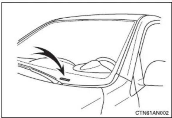
natural_image
Line drawing of a car interior showing a handle and seat, with no text or symbols present.This number is stamped on the top left of the instrument panel.
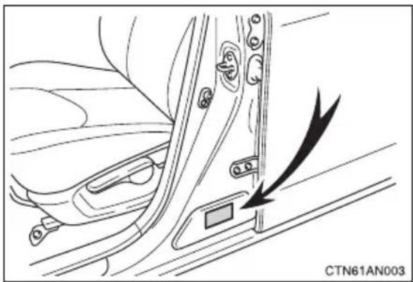
natural_image
Diagram of a car door panel with an arrow pointing to the side panel (no text or symbols present)This number is also on the Certification Label.
Traction motor
Type AC Induction
Traction battery
Type Lithium-ion battery
Overall voltage (Reference) 386 V
Cooling system
Motor coolant
| Capacity (Reference)*1 | 6.1 qt. (5.8 L, 5.1 Imp. qt.) |
| Coolant type “Zerex G 48” or “Glysantin G 48” only * | 2 |
Heater coolant
| Capacity (Reference)*1 | 1.6 qt. (1.5 L, 1.3 Imp. qt.) |
| Coolant type | Use either of the following:“Toyota Super Long Life Coolant”A similar high-quality ethylene glycol-based non-silicate, non-amine, non-nitrite, and non-borate coolant with long-life hybrid organic acid technologyDo not use plain water alone. |
*1: The capacity is a reference quantity. If replacement is necessary, contact your Toyota dealer.
*2: The dilution ratio for both “Zerex G 48” and “Glysantin G 48” is 50% coolant and 50% deionized water.
Electrical system
| 12-volt batteryOpen voltage* at 68°F (20°C): | 12.6 — 12.8 V Fully charged12.2 — 12.4 V Half charged11.8— 12.0 V Discharged(*: Voltage is checked 20 minutes after the EV system and all the lights are turned off) |
| Charging rates 5 A max. |
Transmission
| Fluid capacity (Reference)* 1.26 | qt. (1.2 L, 1.05 Imp. qt.) |
| Fluid type Mobil Dexron VI |
*: The capacity is a reference quantity. If replacement is necessary, contact your Toyota dealer.

NOTICE
■Transmission fluid type
Using transmission fluid other than “Mobil Dexron VI” may cause deterioration in transmission performance, durability, and ultimately damage the transmission of your vehicle.
Brakes
| Pedal clearance*1 | 1.7 in. (44 mm) |
| Pedal free play | 0.04 — 0.12 in. (1 — 3 mm) |
| Brake pad wear limit 0.04 in. (1.0 mm) | |
| Parking brake lining wear limit 0.04 in. (1.0 mm) | |
| Parking brake lever travel*2 | 9 — 11 clicks |
| Fluid type SAE J1703 or FMVSS No. 116 DOT 3 | |
*1: Minimum pedal clearance when depressed with a force of 110 lbf (490 N, 50 kgf) while the EV system is operating
*2: Parking brake lever travel when pulled up with a force of 45 lbf (200 N, 21 kgf)
Steering
| Free play Less than 1.2 in. (30 mm) |
Tires and wheels
| Tire size 225/65R17 101H | |
| Tire inflation pressure (Recommended cold tire inflation pressure) | Front: 32 psi (220 kPa, 2.2 kgf/cm2 or bar) Rear: 32 psi (220 kPa, 2.2 kgf/cm2 or bar) |
| Wheel size 17 × 7 J | |
| Wheel nut torque 76 ft•lbf | (103 N•m, 10.5 kgf•m) |
Light bulbs
| Light bulbs Bulb No. W | Type | |||
| Exterior | HeadlightsHigh beam 9005 60 A | |||
| Front turn signal | 3457NAK | 28/8 C | ||
| Rear side marker lights W5W | 5 | B | ||
| Rear turn signal lights | 7440 21 | C | ||
| Back-up lights | 921 | 18 B | ||
| License plate lights W5W 5 | B | |||
| Interior | Vanity lights | — | 8 | B |
| Front personal lights | — | 8 | B | |
| Interior light | — | 8 | D | |
| Luggage compartment light | — | 5 | D |
A: HB3 halogen bulbs B: Wedge base bulbs (clear)
C: Wedge base bulbs (amber) D: Double end bulbs
Typical tire symbols
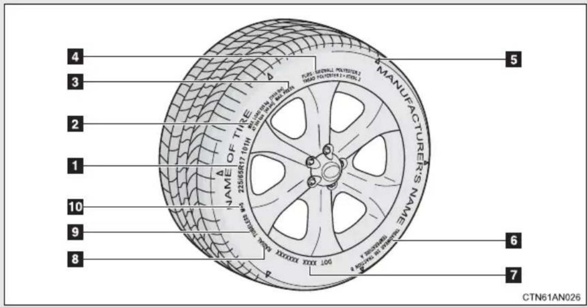
1 Tire size ( P. 491)
2 Load limit at maximum cold tire inflation pressure ( P. 368)
3 Maximum cold tire inflation pressure ( P. 488)
This means the pressure to which a tire may be inflated.
4 Tire ply composition and materials
Plies are layers of rubber-coated parallel cords. Cords are the strands which form the plies in a tire.
5 Location of treadwear indicators ( P. 366)
6 Uniform tire quality grading For details, see “Uniform tire quality grading” that follows.
7 DOT and Tire Identification Number (TIN) (→P. 490)
8 Radial tires or bias-ply tires A radial tire has "RADIAL" on the sidewall. A tire not marked "RADIAL" is a bias-ply tire.
9 TUBELESS or TUBE TYPE
A tubeless tire does not have a tube and air is directly filled in the tire. A tube type tire has a tube inside the tire and the tube maintains the air pressure.
10 Summer tire or all season tire ( P. 369)
An all season tire has “M+S” on the sidewall. A tire not marked “M+S” is a summer tire.
Typical DOT and tire identification number (TIN)
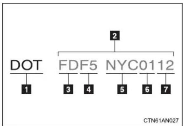
flowchart
graph TD
    A["DOT"] --> B["1"]
    C["FDF5"] --> D["3"]
    C --> E["4"]
    F["NYC0112"] --> G["5"]
    F --> H["6"]
    F --> I["7"]
    J["2"] --> K["..."]
1 DOT symbol*
2 Tire Identification Number (TIN)
3 Tire manufacturer's identification mark
4 Tire size code
5 Manufacturer's optional tire type code (3 or 4 letters)
6 Manufacturing week
7 Manufacturing year
*: The DOT symbol certifies that the tire conforms to applicable Federal Motor Vehicle Safety Standards.
Tire size
■Typical tire size information
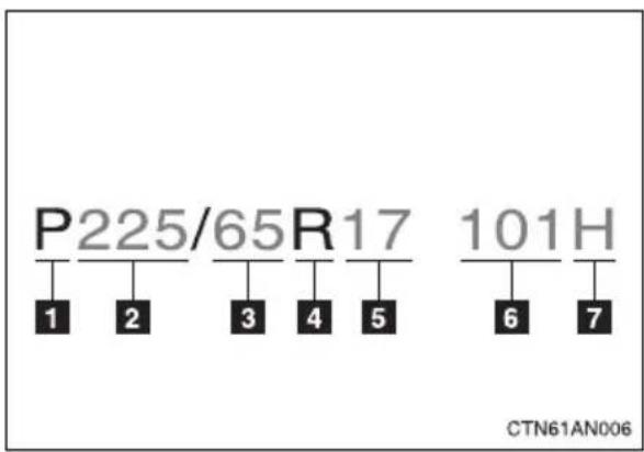
The illustration indicates typical tire size.
1 Tire use (P = Passenger car, T = Temporary use)
2 Section width (millimeters)
3 Aspect ratio (tire height to section width)
4 Tire construction code (R = Radial, D = Diagonal)
5 Wheel diameter (inches)
6 Load index (2 digits or 3 digits)
7 Speed symbol (alphabet with one letter)
Tire dimensions
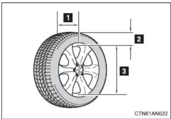
1 Section width
2 Tire height
3 Wheel diameter
Tire section names
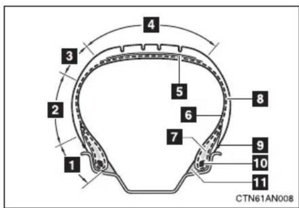
1 Bead
2 Sidewall
3 Shoulder
4 Tread
5 Belt
6 Inner liner
7 Reinforcing rubber
8 Carcass
9 Rim lines
10 Bead wires
11 Chafer
Uniform Tire Quality Grading
This information has been prepared in accordance with regulations issued by the National Highway Traffic Safety Administration of the U.S. Department of Transportation.
It provides the purchasers and/or prospective purchasers of Toyota vehicles with information on uniform tire quality grading.
Your Toyota dealer will help answer any questions you may have as you read this information.
DOT quality grades
All passenger vehicle tires must conform to Federal Safety Requirements in addition to these grades. Quality grades can be found where applicable on the tire sidewall between tread shoulder and maximum section width.
For example: Treadwear 200 Traction AA Temperature A
Treadwear
The treadwear grade is a comparative rating based on the wear rate of the tire when tested under controlled conditions on a specified government test course.
For example, a tire graded 150 would wear one and a half (1 - 1/2) times as well on the government course as a tire graded 100.
The relative performance of tires depends upon the actual conditions of their use, however, and may depart significantly from the norm due to variations in driving habits, service practices and differences in road characteristics and climate.
■Traction AA, A, B, C
The traction grades, from highest to lowest, are AA, A, B and C, and they represent the tire's ability to stop on wet pavement as measured under controlled conditions on specified government test surfaces of asphalt and concrete.
A tire marked C may have poor traction performance.
Warning: The traction grade assigned to this tire is based on braking (straight ahead) traction tests and does not include cornering (turning) traction.
■Temperature A, B, C
The temperature grades are A (the highest), B, and C, representing the tire's resistance to the generation of heat and its ability to dissipate heat when tested under controlled conditions on a specified indoor laboratory test wheel.
Sustained high temperature can cause the material of the tire to degenerate and reduce tire life, and excessive temperature can lead to sudden tire failure.
The grade C corresponds to a level of performance which all passenger car tires must meet under the Federal Motor Vehicle Safety Standard No. 109.
Grades B and A represent higher levels of performance on the laboratory test wheel than the minimum required by law.
Warning: The temperature grades for this tire are established for a tire that is properly inflated and not overloaded.
Excessive speed, underinflation, or excessive loading, either separately or in combination, can cause heat buildup and possible tire failure.
Glossary of tire terminology
| Tire related term Meaning | |
| Cold tire inflation pressure | Tire pressure when the vehicle has been parked for three hours or more, or has not been driven more than 1 mile or 1.5 km under that condition |
| Maximum inflation pressure | The maximum cold inflated pressure to which a tire may be inflated, shown on the sidewall of the tire |
| Recommended inflation pressure | Cold tire inflation pressure recommended by a manufacturer |
| Accessory weight | The combined weight (in excess of those standard items which may be replaced) of automatic transmission, power steering, power brakes, power windows, power seats, radio and heater, to the extent that these items are available as factory-installed equipment (whether installed or not) |
| Curb weight | The weight of a motor vehicle with standard equipment, including the maximum capacity of fuel, oil (for electric vehicle, traction battery) and coolant, and if so equipped, air conditioning and additional weight optional engine (for electric vehicle, traction motor) |
| Maximum loaded vehicle weight | The sum of:(a) Curb weight(b) Accessory weight(c) Vehicle capacity weight(d) Production options weight |
| Normal occupant weight | 150 lb. (68 kg) times the number of occupants specified in the second column of Table 1* that follows |
| Occupant distribution | Distribution of occupants in a vehicle as speci-fied in the third column of Table 1* below |
| Production options weight | The combined weight of installed regular pro-duction options weighing over 5 lb. (2.3 kg) in excess of the standard items which they replace, not previously considered in curb weight or accessory weight, including heavy duty brakes, ride levelers, roof rack, heavy duty 12-volt battery, and special trim |
| Rim | A metal support for a tire or a tire and tube assembly upon which the tire beads are seated |
| Rim diameter (Wheel diameter) | Nominal diameter of the bead seat |
| Rim size designation Rim | diameter and width |
| Rim type designation | The industry manufacturer's designation for a rim by style or code |
| Rim width Nominal distance between rim flanges | |
| Vehicle capacity weight (Total load capacity) | The rated cargo and luggage load plus 150 lb. (68 kg) times the vehicle's designated seating capacity |
| Vehicle maximum load on the tire | The load on an individual tire that is determined by distributing to each axle its share of the maximum loaded vehicle weight, and dividing by two |
| Vehicle normal load on the tire | The load on an individual tire that is determined by distributing to each axle its share of curb weight, accessory weight, and normal occu-pant weight (distributed in accordance with Table 1 * below), and dividing by two |
| Weather side | The surface area of the rim not covered by the inflated tire |
| Bead | The part of the tire that is made of steel wires, wrapped or reinforced by ply cords and that is shaped to fit the rim |
| Bead separation | A breakdown of the bond between components in the bead |
| Bias ply tire | A pneumatic tire in which the ply cords that extend to the beads are laid at alternate angles substantially less than 90 degrees to the centerline of the tread |
| Carcass | The tire structure, except tread and sidewall rubber which, when inflated, bears the load |
| Chunking | The breaking away of pieces of the tread or sidewall |
| Cord The strands forming the plies in the tire | |
| Cord separation | The parting of cords from adjacent rubber compounds |
| Cracking | Any parting within the tread, sidewall, or inner-liner of the tire extending to cord material |
| CT | A pneumatic tire with an inverted flange tire and rim system in which the rim is designed with rim flanges pointed radially inward and the tire is designed to fit on the underside of the rim in a manner that encloses the rim flanges inside the air cavity of the tire |
| Extra load tire | A tire designed to operate at higher loads and at higher inflation pressures than the corresponding standard tire |
| Groove The space between two adjacent tread ribs | |
| Innerliner | The layer(s) forming the inside surface of a tubeless tire that contains the inflating medium within the tire |
| Innerliner separation | The parting of the innerliner from cord material in the carcass |
| Intended outboard sidewall | (a) The sidewall that contains a whitewall, bears white lettering, or bears manufacturer, brand, and/or model name molding that is higher or deeper than the same molding on the other sidewall of the tire, or (b) The outward facing sidewall of an asymmetrical tire that has a particular side that must always face outward when mounted on a vehicle |
| Light truck (LT) tire | A tire designated by its manufacturer as primarily intended for use on lightweight trucks or multipurpose passenger vehicles |
| Load rating | The maximum load that a tire is rated to carry for a given inflation pressure |
| Maximum load rating | The load rating for a tire at the maximum permissible inflation pressure for that tire |
| Maximum permissible inflation pressure | The maximum cold inflation pressure to which a tire may be inflated |
| Measuring rim | The rim on which a tire is fitted for physical dimension requirements |
| Open splice | Any parting at any junction of tread, sidewall, or innerliner that extends to cord material |
| Outer diameter The overall diameter of an inflated new tire | |
| Overall width | The linear distance between the exteriors of the sidewalls of an inflated tire, including elevations due to labeling, decorations, or protective bands or ribs |
| Passenger car tire | A tire intended for use on passenger cars, multipurpose passenger vehicles, and trucks, that have a gross vehicle weight rating (GVWR) of 10,000 lb. or less. |
| Ply A layer of rubber-coated parallel cords | |
| Ply separation | A parting of rubber compound between adjacent plies |
| Pneumatic tire | A mechanical device made of rubber, chemicals, fabric and steel or other materials, that, when mounted on an automotive wheel, provides the traction and contains the gas or fluid that sustains the load |
| Radial ply tire | A pneumatic tire in which the ply cords that extend to the beads are laid at substantially 90 degrees to the centerline of the tread |
| Reinforced tire | A tire designed to operate at higher loads and at higher inflation pressures than the corresponding standard tire |
| Section width | The linear distance between the exteriors of the sidewalls of an inflated tire, excluding elevations due to labeling, decoration, or protective bands |
| Sidewall | That portion of a tire between the tread and bead |
| Sidewall separation | The parting of the rubber compound from the cord material in the sidewall |
| Snow tire | A tire that attains a traction index equal to or greater than 110, compared to the ASTM E-1136 Standard Reference Test Tire, when using the snow traction test as described in ASTM F-1805-00, Standard Test Method for Single Wheel Driving Traction in a Straight Line on Snow-and Ice-Covered Surfaces, and which is marked with an Alpine Symbol (on at least one sidewall |
| Test rim | The rim on which a tire is fitted for testing, and may be any rim listed as appropriate for use with that tire |
| Tread | That portion of a tire that comes into contact with the road |
| Tread rib | A tread section running circumferentially around a tire |
| Tread separation Pulling | away of the tread from the tire carcass |
| Treadwear indicators (TWI) | The projections within the principal grooves designed to give a visual indication of the degrees of wear of the tread |
| Wheel-holding fixture | The fixture used to hold the wheel and tire assembly securely during testing |
*:Table 1 — Occupant loading and distribution for vehicle normal load for various designated seating capacities
| Designated seating capacity, Number of occupants | Vehicle normal load, Number of occupants | Occupant distribution in a normally loaded vehicle |
| 2 through 4 2 2 in front | ||
| 5 through 10 3 | 2 in front, 1 in second seat | |
| 11 through 15 5 | 2 in front, 1 in second seat, 1 in third seat, 1 in fourth seat | |
| 16 through 20 7 | 2 in front, 2 in second seat, 2 in third seat, 1 in fourth seat |
Your vehicle includes a variety of electronic features that can be personalized to your preferences. Programming these preferences requires specialized equipment and may be performed by your Toyota dealer.
Some function settings are changed simultaneously with other functions being customized. Contact your Toyota dealer.
| Item Function | Default setting | Customized setting | |
| Smart key system (→P. 96) | Smart key system On Off | ||
| Operation signal (Emergency flashers) | On Off | ||
| Operation signal (Buzzer) | On Off | ||
| Wireless remote control (→P. 108) | Wireless remote control On Off | ||
| Unlocking operation | Driver's door unlocked in one step, all doors unlocked in two steps | All doors unlocked in one step | |
| Automatic door lock function to be activated if door is not opened after being unlocked | On Off | ||
| Time elapsed before automatic door lock function is activated if door is not opened after being unlocked | 60 seconds | 30 seconds | |
| 120 seconds | |||
| Operation signal (Emergency flashers) | On Off | ||
| Door lock buzzer On Off | |||
| Operation signal (Buzzer) | On Off | ||
| Door lock(→P. 110,468) | Unlocking using a key | Driver's door unlocked in one step, all doors unlocked in two steps | All doors unlocked in one step |
| Automatic light control system(→P. 234) | Light sensor sensitivity Level 3 Level 1 to 5 | ||
| Time elapsed before headlights automatically turn off after doors are closed | 30 seconds | 0 second | |
| 60 seconds | |||
| 90 seconds | |||
| Lights(→P. 234) | Daytime running light system | On Off | |
| Illumination(→P. 293) | Time elapsed before lights turn off | 15 seconds | 7.5 seconds |
| 30 seconds | |||
| Operation when the doors are unlocked | On Off | ||
| Operation after the “POWER” switch is turned off | On Off | ||
| Footwell lights On Off | |||
| Seat belt reminder(→P. 419) | Vehicle speed linked seat belt reminder buzzer | On Off | |
Navigation system\*
Settings that can be changed using the navigation system
| Available languages English, French and Spanish | |
| Available units miles (miles/kWh), km (km/kWh) |
*: Refer to "Navigation System Owner's Manual".
The following items must be initialized for normal system operation in cases such as after the 12-volt battery is reconnected, or maintenance is performed on the vehicle.
| Item When to initialize Reference | ||
| Power window | After reconnecting or changing the 12-volt battery | P. 147 |
6-3. Initialization
For owners
7
Reporting safety defects for U.S. owners.... 506
If you believe that your vehicle has a defect which could cause a crash or could cause injury or death, you should immediately inform the National Highway Traffic Safety Administration (NHTSA) in addition to notifying Toyota Motor Sales, U.S.A., Inc. (Toll-free: 1-800-331-4331).
If NHTSA receives similar complaints, it may open an investigation, and if it finds that a safety defect exists in a group of vehicles, it may order a recall and remedy campaign. However, NHTSA cannot become involved in individual problems between you, your dealer, or Toyota Motor Sales, U.S.A., Inc.
To contact NHTSA, you may call the Vehicle Safety Hotline toll-free at 1-888-327-4236 (TTY: 1-800-424-9153); go to http://www.safercar.gov; or write to: Administrator, NHTSA, 1200 New Jersey Ave, S.E., Washington, DC 20590. You can also obtain other information about motor vehicle safety from http://www.safercar.gov.
Index
Abbreviation list 508
Alphabetical index...... 509
What to do if... 518
For details of equipment related to the navigation system and such as the audio system, refer to the “Navigation System Owner's Manual”.
| ABBREVIATIONS MEANING | |
| A/C Air Conditioning | |
| ABS Anti-lock Brake System | |
| ACC Accessory | |
| ALR Automatic Locking Retractor | |
| CRS Child Restraint System | |
| DISP Display | |
| ECU Electronic Control Unit | |
| EDR Event Data Recorder | |
| ELR Emergency Locking Retractor | |
| EPS Electric Power Steering | |
| EV Electric Vehicle | |
| GAWR Gross Axle Weight Rating | |
| GVWR Gross Vehicle Weight Rating | |
| LATCH Lower Anchors and Tethers for Children | |
| LED Light Emitting Diode | |
| M+S Mud and Snow | |
| SOC State of Charge | |
| SRS Supplemental Restraint System | |
| TIN Tire Identification Number | |
| TPMS Tire Pressure Warning System | |
| TRAC Traction control | |
| VIN Vehicle Identification Number | |
| VSC Vehicle Stability Control |
A
A/C 276
ABS.... 251
Active head restraints...... 120
Air conditioning filter...... 381
Air conditioning system
Air conditioning filter...... 381
Automatic air conditioning system ...... 276
Pre-climate 53,277
Remote Climate Control .... 53, 277
Airbags
Airbag operating conditions.... 156, 157
Airbag precautions for your child.... 161
Airbag warning light...... 418
Curtain shield airbag operating conditions...... 157
Curtain shield airbag precautions .... 161
Front passenger occupant classification system ...... 166
General airbag precautions .... 161
Locations of airbags...... 154
Modification and disposal of airbags 165
Proper driving posture.... 152, 161
Side airbag operating conditions.... 157
Side airbag precautions..... 161
SRS airbags 154
Anti-lock brake system...... 251
Armrest 313
Assist grips.... 315
Automatic air conditioning system...... 276
Automatic light control system 234
Auxiliary box.... 302
B
Back-up lights
Replacing light bulbs.....400
Wattage....488
Back door
Back door....113
Smart key system....96
Wireless remote control .....108
Battery
Checking (12-volt battery).....362
If the vehicle 12-volt battery is discharged....470
Lithium-ion battery....34
Preparing and checking before winter....268
Traction battery 32
Bottle holder....300
Brake assist....251
Brakes
Fluid 361
Parking brake......216
Break-in tips ......191
C
Care
Exterior......334
Interior......337
Seat belts 338
Cargo capacity 267
Cargo hooks......317
Chains....268
Charging
Charge immediately......53, 64
Charge mode 58
Charging cable......47
Charging equipment......46
Charging indicator....59
Charging messages .....443
Charging precautions......84
Charging procedure ....53
Charging time will increase when 79
How to charge your vehicle.....53
High voltage components......32
Information related to charging display....74
Maintenance....92
Power sources precautions.....52
Power sources that can be used....50
Pre-Climate....53
Remote Climate Control ....53, 277
Safety functions......48, 82
When charging cannot be carried out....88
Charging port door 46
Charging station information....520
Child restraint system
Booster seats, definition......172
Booster seats, installation .....176
Convertible seats, definition ....172
Convertible seats, installation....176
Front passenger occupant classification system......166
Infant seats, definition .....172
Infant seats, installation......176
Installing CRS with a top tether strap....183
Installing CRS with LATCH anchors....178
Installing CRS with seat belts ....180
Child safety
Airbag precautions......161
Child restraint system......172
Child-protectors......111
How your child should wear the seat belt....135
Installing child restraints......176
Power window lock switch.....146
Power window precautions ...148
Removed key battery precautions....384
Seat belt extender precautions....138
Seat belt precautions ......136
Seat heater precautions......312
12-volt battery precautions......363, 473
Child-protectors......111
Cleaning
Exterior......334
Interior......337
Seat belts....338
Coat hooks......314
Condenser....360
Console box......298
Cooling system
Overheating 475
Cruise control 243
Cup holders....299
Curtain shield airbags......154
Customizable features ....500
D
Daytime running light system......236
Daytime running lights
Replacing light bulb......400
Switch 234
Defogger
Rear window....292
Side mirrors....292
Dimensions 482
Dinghy towing....274
Display
Multi-information display.....227
Trip information......227
Do-it-yourself maintenance ....346
Door courtesy lights
Door courtesy lights......293
Wattage....488
Doors
Back door.... 113
Door lock 96,108
Door window.... 146
Rear door child protector..... 111
Side doors 110
Side mirrors.... 143
Driver's seat belt reminder
light 419
Driving
Break-in tips 191
Correct posture...... 152
Procedures.... 190
Winter driving tips.... 268
E
Electric power steering...... 251
Electric vehicle.... 26
Electronic key
If your electronic key battery is discharged...... 468
Emergency flasher
Switch...... 412
Emergency tire puncture
repair kit.... 447
Emergency, in case of
If a warning buzzer sounds... 417
If a warning light turns on.... 417
If a warning message is displayed.... 427
If the electronic key does not operate properly...... 468
If the EV (Electric Vehicle) system will not start...... 465
If the vehicle 12-volt battery is discharged...... 470
If you have a flat tire ..... 447
If you lose your keys...... 467
If you think something is wrong 416
If your vehicle becomes stuck.... 477
If your vehicle has to be stopped in an emergency....479
If your vehicle needs to be towed ....413
If your vehicle overheats.....475
Energy monitor
Past record screen......40
Trip information screen ......38
EPS......251
EV (Electric Vehicle) system
Charging....53
Driving tips ......41
Emergency shut off system.....33
Energy monitor/ consumption screen......38
EV System Indicator......221
EV (Electric Vehicle) system precautions ....32
High voltage components.....32
How to start the EV system...200
If the EV (Electric Vehicle) system will not start .....465
"POWER" switch .....200
Vehicle Proximity Notification System......31
Event data recorder ......19
Extended charge mode .....58
F
Floor mat......316
Fluid
Brake....361
Washer....365
Front passenger occupant classification system ....166
Front passenger's seat belt reminder light....419
Front seats
Adjustment ......118
Front side marker lights
Switch....234
G
Front turn signal lights
Replacing light bulbs......400
Wattage....488
Fuses....385
Garage door opener....320
Gauges......218
Glove box....297
Grocery bag hooks ....317
H
Hazard lights
Switch......412
Head restraints
Adjusting 127
Headlight aim 398
Headlights
Replacing light bulbs......400
Switch....234
Wattage....488
Heater coolant
Capacity....485
Checking 359
Preparing and checking before winter....268
Heaters
Seat heaters....310
Side mirrors....292
Hill-start assist control......251
Hood....349
Hooks
Cargo hook....317
Grocery bag 317
Horn......217
|
Identification
Motor....483
Tire....489
Vehicle 483
Illuminated entry system......295
Immobilizer system .....149
Indicator lights....223
Initialization
Items to initialize ....503
Inside rear view mirror .....141
Interior light
Switch 295
Wattage....488
J
Jack
Jack stand....352
Positioning a floor jack......351
Positioning a jack stand .....352
K
Keyless entry ......108
Keys
Electronic key....94
If the electronic key does not operate properly ....468
If you lose your keys .....467
Key battery....383
Key number......94
Keyless entry ......108
Keys....94
Mechanical key 94
"POWER" switch.....202
Wireless remote control key......108
L
License plate lights
Replacing light bulbs ..... 400
Wattage 488
Light bulbs
Replacing 400
Wattage.... 488
Lights
Door courtesy lights...... 293
Emergency flasher switch .... 412
Hazard light switch 412
Headlight switch.... 234
Interior light switch..... 294, 295
Luggage compartment light 295
Personal light switch...... 294
Replacing light bulbs 400
Turn signal lever...... 215
Vanity lights.... 305
Wattage.... 488
Load capacity 267
Lock steering column...... 204
Luggage compartment light
Switch.... 295
Wattage 488
M
Maintenance
Do-it-yourself maintenance ....346
General maintenance......342
Maintenance data....482
Maintenance requirements....340
Meter
Instrument panel light control.....219
Meters 218
Mirrors
Inside rear view mirror......141
Side mirror heaters......292
Side mirrors....143
Vanity mirrors....305
Motor
Compartment 355
Hood....349
Identification number......483
Motor compartment cover.....356
Motor coolant
Capacity......485
Checking 357
Preparing and checking before winter....268
Multi-information display .....227
N
Navigation system screen
operations ....44
Touch 44
Double Tap....44
Drag 44
Flick....44
Noise specific to an electric
vehicle 30
Normal charge mode ....58
O
Odometer......218
Opener
Charging port door 59
Hood....349
Outside rear view mirrors
Adjusting and folding......143
Defogger 292
Overheat 475
P
Parking brake 216
Parking lights
Replacing light bulbs......400
Switch....234
Personal/interior lights
Switch....294
Wattage....488
Power outlet ....306
"POWER" switch.....200
Power windows....146
Pre-climate (Remote Climate Control)
Pre-climate....53, 277
Pre-climate schedule....53
Remote Climate
Control 53,277
R
Radiator 360
Range map ......28
Rear seat
Adjustment......121
Folding down......122
Rear side marker lights
Replacing light bulb......400
Switch 234
Wattage....488
Rear turn signal lights
Replacing light bulbs......400
Wattage....488
Rear view monitor system .....247
Rear window defogger .....292
Rear window wiper 241
Regenerative braking......27, 29
Remote Climate Control system....53
Replacing
Fuses 385
Key battery....383
Light bulbs....400
Tires....366
Reporting safety defects for
U.S. owners....506
S
Safety Connect.... 326
Seat belts
Adjusting the seat belt..... 131
Automatic Locking Retractor .... 134
Child restraint system installation.... 176
Cleaning and maintaining the seat belts.... 338
Emergency Locking Retractor .... 120
How to wear your seat belt... 131
How your child should wear the seat belt 135
Pregnant women, proper seat belt use .... 136
Reminder light 419
Seat belt extenders 135
Seat belt pretensioners ..... 134
Seat heaters.... 310
Seating capacity...... 267
Seats
Adjustment 118, 121
Adjustment precaution .... 120, 125
Child seats/child restraint system installation...... 176
Cleaning 337
Head restraints.... 127
Properly sitting in the seat.... 152
Seat heaters.... 310
Service reminder
indicators 223
Shift lever
Transmission.... 206
Side airbags.... 154
Side marker lights
Replacing light bulbs 400
Switch.... 234
Wattage 488
Side mirrors
Adjusting and folding...... 143
Side turn signal lights
Replacing light bulb......400
Wattage....488
Smart key system
Entry function ......96
Starting the EV system......200
"SOS" button....326
Specifications......482
Speedometer 218
Steering
Column lock release......204
Steering wheel
Adjustment 140
Stop lights
Replacing light bulbs......400
Storage feature......296
Storage precautions ......265
Stuck
If your vehicle becomes stuck ....477
Sun visors....304
Switch
Cruise control....243
“DISP” switch .....227
Emergency flasher switch.....412
Hazard light switch......412
Light switches......234
Power door lock switch .....110
"POWER" switch .....200
Power window switches .....146
SPORT mode switch......208
VSC OFF switch.....252
Window lock switch......146
Wiper and washer switch......238, 241
T
Tail lights
Replacing light bulbs......400
Switch....234
Theft deterrent system
Immobilizer system .....149
Theft prevention labels......151
Tire inflation pressure ......374
Tire information
Glossary......494
Size 491
Tire identification number.....490
Uniform tire quality grading....492
Tires
Chains....268
Checking 366
If you have a flat tire......447
Inflation pressure......374
Information 489
Replacing 366
Rotating tires....366
Size 488
Snow tires 268
Tire pressure warning system ....366, 419
Total load capacity......267
Towing
Dinghy towing....274
Emergency towing......413
Trailer towing......273
Traction control......251
Traction battery coolant
Checking 357
Preparing and checking before winter....268
TRAC....251
Transmission
P position switch .....209
Transmission......206
Trip information ......227
Trip meter 218
Turn signal lights
Replacing light bulbs......400
Switch 215
Wattage....488
U
Utility vehicle precautions.....258
V
Vanity lights
Vanity lights....305
Wattage....488
Vanity mirrors ....305
Vehicle data recordings .....19
Vehicle identification
number 483
Vehicle Stability Control .....251
VSC 251
W
Warning buzzers
Brake system 417
Electric power steering system ....418
Key reminder......440
Master warning 419
Open door....419
Output control warning......419
Seat belt reminder......419
Warning lights
Anti-lock brake system ..... 418
Brake assist system 418
Brake system...... 417
Electric power steering...... 418
Master warning...... 419
Open door 419
Output control warning ..... 419
Plug-in indicator...... 419
Pretensioners 418
Seat belt reminder light ..... 419
Slip indicator light 418
SOC (State of Charge) warning 419
SRS airbags 418
Tire pressure warning light... 419
12-volt battery charging system.... 418
Warning messages 427
Washer
Checking 365
Preparing and checking before winter 268
Switch.... 238, 241
Washing and waxing...... 334
Weight
Cargo capacity 263
Load limits 267
Weight 482
Wheels.... 378
Window glasses 146
Window lock switch...... 146
Windows
Power windows 146
Rear window defogger ..... 292
Washer.... 238, 241
Windshield wipers...... 238
Wireless remote control key
Replacing the battery ..... 383
Wireless remote control key 108
A tire punctures
P. 447 If you have a flat tire
The EV system does not start
P. 465 If the EV system will not start
P. 149 Immobilizer system
P. 470 If the 12-volt battery is discharged
Steam can be seen coming from under the hood
P. 475 If your vehicle overheats
The key is lost
P. 467 If you lose your keys
The 12-volt battery runs out
P. 470 If the 12-volt battery is discharged
The doors cannot be locked
P. 110 Side doors
P. 113 Back door
The vehicle is stuck in mud or sand
P. 477 If the vehicle becomes stuck
A warning light or indicator light comes on
P. 417 If a warning light turns off of a warning buzzer sounds...
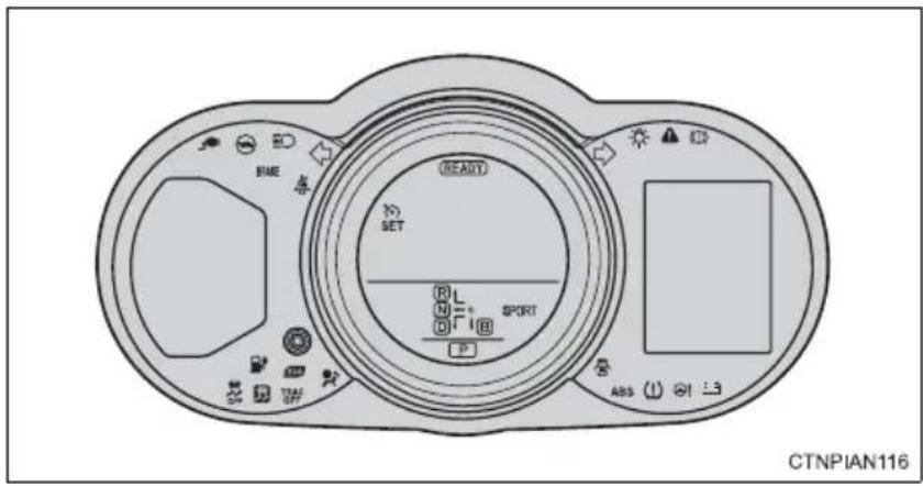
■Warning lights
Brake system warning light P. 417 P. 418
Cruise control indicator light*1
12-volt battery charging sys- tem warning light P. 418 P. 419
Master warning light
SRS warning light P. 418 P. 418
Electric power steering sys- tem warning light
Open door warning light P. 419 P. 419
Driver's/front passenger's seat belt reminder light
Brake system warning light (yellow indicator) P. 418 P. 418
"ABS" warning light
SOC (State of Charge) warning light P. 419 P. 419
Tire pressure warning light
Output control warning light P. 419 P. 418
Slip indicator light
natural_image
Simple line drawing of a curved object with two circular holes, resting on a horizontal surface (no text or symbols)Charging indicator ^*2 P. 419
Plug-in indicator (yellow indicator) P. 419
*1: The light flashes to indicate a malfunction.
*2: Both lights flash quickly for 10 seconds to indicate that the system is malfunctioning.
CHARGING STATION INFORMATION
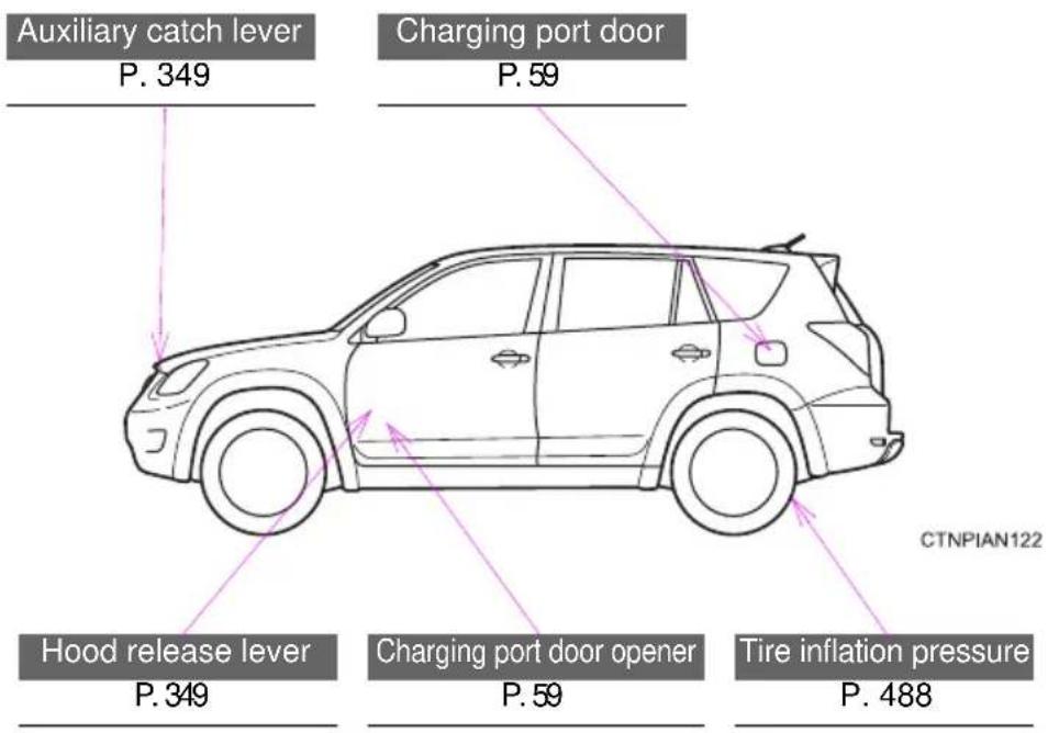
| Power sources | AC120 V, 240 V electrical receptacles (NEMA 5-15R or NEMA 5-20R) |
| Charger type AC charger (SAE | J1772 level1/level2) |
| Time needed for charging* | P. 78 |
| Traction battery type Lithium-ion battery | |
| Cold tire inflation pressure | P. 488 |
*: Gives an estimation of the amount of time needed to charge fully from an EV driving range of 0 mile (0 km).
For the charge procedure, refer to "Charging and pre-climate
(Remote Climate Control) procedures" in section 1 (→P. 53).
Handling may differ in accordance with the type of plug provided at the charging station. Check at each station.
- Before driving
- 1-1. EV system
- 1-2. Navigation system screen operations
- 1-3. Charging
- 1-4. Key information
- 1-5. Opening, closing and locking the doors
- 1-6. Adjustable components (seats, mirrors, steering wheel)
- 1-7. Opening and closing the windows
- 1-8. Theft deterrent system
- 1-9. Safety information
- When driving
- 2-1. Driving procedures
- 2-2. Instrument cluster
- 2-3. Operating the lights and wipers
- 2-4. Using other driving systems
- 2-5. Driving information
- Interior features
- 3-1. Using the air conditioning system and defogger
- 3-2. Using the interior lights
- 3-3. Using the storage features
- 3-4. Other interior features
- Maintenance and care
- 4-1. Maintenance and care
- 4-2. Maintenance
- 4-3. Do-it-yourself maintenance
- When trouble arises
- 5-1. Essential information
- 5-2. Steps to take in an emergency
- Vehicle specifications
- 6-1. Specifications
- 6-2. Customization
- 6-3. Initialization
- For owners
- Index
- Pictorial index
- Exterior
- Interior
- A
- B
- Instrument panel
- C
- Luggage compartment
- For your information
- Main Owner's Manual
- Accessories, spare parts and modification of your Toyota
- Installation of a mobile two-way radio system
- Vehicle data recordings
- Event data recorder
- Scrapping of your Toyota
- Perchlorate Material
- CAUTION
- ■General precautions while driving
- ■General precaution regarding children's safety
- ■Traction battery
- ■Disposal of the traction battery
- Symbols used throughout this manual
- Cautions & Notices
- NOTICE
- Symbols used in illustrations
- Safety symbol
- Arrows indicating operations
- Before driving
- 1
- Charging
- ■When braking (regenerative braking)
- Vehicle Proximity Notification System
- "Range map" screen
- ■ Regenerative braking
- ■12-volt battery recharging
- ■When not using the vehicle for an extended period of time
- ■Driving Range
- ■Noise and vibrations specific to an electric vehicle
- If the amount of charge remaining in the traction battery becomes low
- ■ Vehicle Proximity Notification System
- ■Maintenance, Repair and Disposal
- Emergency shut off system
- Warning message
- If a warning light comes on, a warning message is displayed, or the 12-volt battery has been disconnected
- Electromagnetic waves
- ■Traction battery (Lithium-ion battery)
- ■High voltage precautions
- Road accident cautions
- ■ Traction battery (lithium-ion battery) replacement and disposal
- ■Caution while driving
- Trip Information screen/Past record screen
- ■Trip information screen
- Past record screen
- ■Driving in normal mode:
- Route selection
- ■Use of EV System Indicator
- ■When braking the vehicle
- ■ Highway driving
- Air conditioning system
- ■ Checking tire inflation pressure
- Luggage
- ■Pre-driving warm-up
- When the charging schedule is set
- When the charging schedule is not set
- ■Sport mode
- Navigation system screen operations
- ■Navigation system screen operations
- ■When using the navigation system screen
- ■The names of each part of the charging cable
- Safety functions
- ■Electrical leakage detection function
- ■Electrical leakage test function
- ■Conditions for supplying current to the vehicle
- Charging method
- ■ When using the charging cable and CCID (Charging Circuit Interrupting Device)
- Power sources
- ■Electrical receptacles that can be connected
- ■The charging environment
- ■ Using a DC charger
- Electrical Malfunctions
- ■Power sources precautions
- ■Charging and pre-climate (Remote Climate Control)
- ■ Important things to check before charging and pre-climate operations (Remote Climate Control)
- ■Items to be regularly inspected
- ■By My Departure Schedule Setting
- Charge and Pre-Climate Schedule Setting Screen
- Charge mode
- ■Linked smart phone function
- Plugging in the charging cable
- STEP 1 Prepare the charging cable
- Charging immediately
- ■ Charging using the Charge Immediately function
- When the charging schedule is not set or charging immediately has been set while the EV system was on.
- When the charging schedule is set.
- ■Setting charge mode to charge immediately in advance
- STEP 5 Turn the EV system off.
- To change charging mode to normal/extended charge mode: →P.72
- STEP 6 Plug in the charging cable ( → P. 59)
- Start charging according to departure time and the set pre-climate completion time
- ■Setting the charging and pre-climate schedule in advance
- ■Adjusting the charge schedule's next departure after the schedule has been set (One time departure)
- STEP 1 Turn the EV system off.
- Changing to normal/extended charge mode
- Touch "Extended Charge".
- To normal charge mode
- To extended charge mode
- Unplugging the charging cable
- Contents shown on the multi-information display
- ■Results of Charging and Pre-climate Display
- ■ Charging information and warning messages
- Confirming current charge settings
- ■When leaving the vehicle
- ■ Amount of time required for charging
- ■ Automatic OFF function when the charging cable is connected
- ■Default charge mode setting
- Charge mode setting
- During charging
- ■If charging has been interrupted
- ■ Charging time may increase
- ■ Capacity reduction of the traction battery
- If the amount of charge remaining in the traction battery becomes low while driving
- - Charging schedule confirmation display after switching the EV system off
- ■If the charging port door is frozen
- ■Pre-climate operations automatic shut-off
- ■While pre-climate is operating
- ■Safety functions
- If charging has not been carried out in a long time
- ■When the outside temperature is low or high
- ■ Charging in extremely cold temperatures
- ■Handling the traction battery
- When charging
- ■Precautions for the pre-climate
- If the error warning indicator on the CCID (Charging Circuit Interrupting Device) stays on during charging
- ■When the charging cable is connected to the vehicle
- ■After charging
- ■ Using private power generators
- ■ Usable temperature range
- A problem has occurred during charging
- If a warning message is displayed after charging
- ■ Resetting the CCID (Charging Circuit Interrupting Device)
- Inspecting the electrical leakage detection function
- ■Routine inspection
- ■Maintaining the charging cable
- ■When not using the charging cable for a long time
- The following keys are provided with the vehicle.
- Electronic keys
- Using the mechanical key
- ■ When required to leave a key to the vehicle with a parking attendant
- ■Key number plate
- ■When riding in an aircraft
- ■To prevent key damage
- Unlocking and locking the doors and back door (front and back door handles only)
- Antenna location and effective range
- Antenna location
- ■Effective range (areas within which the electronic key is detected)
- Operation signals
- ■Alarms and warning indicators
- ■Security feature
- ■Switching the door unlock function
- ■Battery-saving function
- ■Conditions affecting operation
- ■Note for the entry function
- ■ When the vehicle is not driven for extended periods
- ■To operate the system properly
- If the smart key system does not operate properly
- Electronic key battery depletion
- ■When the electronic key battery is fully depleted
- ■ Customization that can be configured at Toyota dealer
- ■Certification for the smart key system
- NOTE:
- FCC WARNING:
- ■ Caution regarding interference with electronic devices
- ■Panic mode
- ■Door lock buzzer
- ■Key battery depletion
- If the wireless remote control does not operate
- ■ Customization that can be configured at your Toyota dealer
- ■Certification for wireless remote control
- Side doors
- Entry function
- ■ Wireless remote control
- ■Door lock switch
- Inside lock buttons
- Locking the front doors from the outside without the wireless remote control or key
- Rear door child-protector lock
- ■ Using the mechanical key
- - When all the doors are locked with the entry function, wireless remote control or key
- ■The doors cannot be locked when
- ■To prevent an accident
- Back door
- Rear step bumper
- Luggage compartment light
- ■Caution while parking
- ■When children are in the vehicle
- ■Operating the back door
- ■To prevent damage to the back door components
- ■To prevent 12-volt battery discharge
- 1-6. Adjustable components (seats, mirrors, steering wheel) Front seats
- Flattening the front seatbacks
- ■Before flattening the front seatbacks
- ■Flattening the front seatbacks
- Active head restraints
- ■Active head restraints
- ■Seat adjustment
- 1-6. Adjustable components (seats, mirrors, steering wheel) Rear seats
- Folding down the rear seatbacks
- ■Before folding down the rear seatbacks
- ■Folding down the rear seatbacks
- From inside
- From outside
- ■When folding the rear seatbacks down
- ■After adjusting a seat
- ■ Stowing the seat belts
- 1-6. Adjustable components (seats, mirrors, steering wheel) Head restraints
- ■Removing the head restraints
- Front seats
- Rear seats
- ■Installing the head restraints
- ■Adjusting the height of the head restraints
- ■Adjusting the rear center seat head restraint
- ■Head restraint precautions
- 1-6. Adjustable components (seats, mirrors, steering wheel) Seat belts
- ■ Correct use of the seat belts
- ■Fastening and releasing the seat belt
- ■ Adjusting the seat belt shoulder anchor height (front seats)
- Rear center seat belt
- ■Releasing method
- Seat belt pretensioners (front seats)
- Emergency locking retractor (ELR)
- ■Automatic locking retractor (ALR)
- ■When not using the outer rear seat belts
- ■Child seat belt usage
- ■Replacing the belt after the pretensioner has been activated
- ■Seat belt extender
- ■Wearing a seat belt
- ■ Pregnant women
- ■People suffering illness
- ■Seat belt pretensioners
- ■Adjustable shoulder anchor
- ■Seat belt damage and wear
- ■When using the rear center seat belt
- ■ Using a seat belt extender
- ■When using a seat belt extender
- 1-6. Adjustable components (seats, mirrors, steering wheel) Steering wheel
- The steering wheel can be adjusted to a comfortable position.
- ■After adjusting the steering wheel
- 1-6. Adjustable components (seats, mirrors, steering wheel) Anti-glare inside rear view mirror
- Adjusting the height of rear view mirror
- Automatic anti-glare function
- ■To prevent sensor error
- 1-6. Adjustable components (seats, mirrors, steering wheel) Outside rear view mirrors
- Mirror angle can be adjusted using the switch.
- Folding the mirrors
- ■Mirror angle can be adjusted when
- ■When the mirrors are fogged up
- ■When driving the vehicle
- ■When a mirror is moving
- ■When the mirror defoggers are operating
- The power windows can be opened and closed using the switches.
- Window lock switch
- ■The power windows can be operated when
- - Operating the power windows after turning the “POWER” switch off (front windows only)
- Jam protection function (driver's window only)
- - When the power window does not close normally (driver's window only)
- STEP 1
- STEP 2
- STEP 3
- ■ Closing the windows
- ■Jam protection function (driver's window only)
- System maintenance
- ■Certifications for the immobilizer system
- ■To ensure the system operates correctly
- Theft prevention labels
- Drive with a good posture as follows:
- ■While driving
- ■Adjusting the seat position
- SRS front airbags
- SRS side and curtain shield airbags
- Airbag system components
- ■If the SRS airbags deploy (inflate)
- ■ SRS airbag deployment conditions (SRS front airbags)
- ■ SRS airbag deployment conditions (SRS side and curtain shield airbags)
- ■Conditions under which the SRS airbags may deploy (inflate), other than a collision
- ■ Types of collisions that may not deploy the SRS airbags (SRS front airbags)
- ■Types of collisions that may not deploy the SRS airbags (SRS side and curtain shield airbags)
- ■When to contact your Toyota dealer
- ■ SRS airbag precautions
- ■SRS airbag precautions
- ■ Modification and disposal of SRS airbag system components
- Front passenger occupant classification system
- Conditions and operation of the front passenger occupant classification system
- Adult\* 1
- ■Child\* 3 or child restraint system\* 4
- ■ Front passenger occupant classification system precautions
- Points to remember
- Types of child restraints
- Rear facing — Infant seat/convertible seat
- Forward facing — Convertible seat
- Booster seat
- ■Selecting an appropriate child restraint system
- ■Child restraint precautions
- ■When the child restraint system is not in use
- Installation with LATCH system (rear outside seats only)
- Type A
- Type B
- Installing child restraints using a seat belt (child restraint lock function belt)
- ■ Rear facing — Infant seat/convertible seat
- ■ Forward facing — Convertible seat
- ■ Booster seat
- Removing a child restraint installed with a seat belt
- Child restraint systems with a top tether strap (rear seats only)
- ■Outside seats
- Center seat
- ■Laws and regulations pertaining to anchorages
- ■When installing a booster seat
- ■When installing a child restraint system
- ■Do not use a seat belt extender
- ■ To correctly attach a child restraint system to the anchors
- When driving
- 2
- Starting on a steep uphill
- - Driving in the rain
- ■Breaking in your new Toyota
- ■Drum-in-disc type parking brake system
- ■Operating your vehicle in a foreign country
- For efficient use
- ■When starting the vehicle
- ■When driving on slippery road surfaces
- ■When changing the shift position
- If you hear a squealing or scraping noise (brake pad wear limit indicators)
- ■When the vehicle is stopped
- ■When the vehicle is parked
- ■When taking a nap in the vehicle
- ■Avoiding damage to vehicle parts
- ■If you get a flat tire while driving
- ■When encountering flooded roads
- Starting the EV system
- ■Stopping the EV system
- ■Changing "POWER" switch mode
- Off
- ACCESSORY mode
- ON mode
- ■Auto power off function
- ■ Sounds and vibrations specific to a electric vehicle
- ■Auto P position function
- ■ When the ambient temperature is low, such as during winter driving conditions
- ■When the P position control system malfunctions
- ■If the EV system does not start
- ■When the steering lock cannot be released
- ■When the "POWER" switch indicator flashes in amber
- If the "READY" indicator does not come on
- ■If the EV system is malfunctioning
- ■When the electronic key battery is discharged
- ■When starting the EV system
- ■Stopping the EV system in an emergency
- ■Shifting the shift lever
- Shift lever
- Shift position indicator
- Shift position purpose
- P position switch
- ■When shifting the shift position to P
- ■Shifting the shift position from P to other positions
- For the shift positions
- ■Reverse warning buzzer
- ■Automatically P position selection function
- If the shift position cannot be shifted from P
- ■ Using regenerative braking
- ■If the system malfunctions
- ■When sport mode is selected
- Alarms
- ■To avoid an accident
- For the shift lever
- ■P position switch
- ■ Situations where P position control system malfunctions are possible
- Notes regarding shift lever and P position switch operation
- ■Turn signals can be operated when
- ■If the indicators flash faster than usual
- Horn
- Odometer/trip meter
- Odometer
- Trip meter
- Display change button
- Instrument panel light control
- Eco Driving Indicator Light and turn-by-turn navigation display customization
- ■The meters and display illuminate when
- ■EV System Indicator
- ■The brightness of the instrument panel lights
- Indicators and warning lights
- Indicators
- ■Warning lights
- If a safety system warning light does not come on
- ■Display contents
- Trip information
- Efficiency
- Average power consumption
- Current power consumption
- Trip efficiency
- ECO coach
- CO _2 reduction
- AUX Power
- Average 12-volt battery consumption
- Current 12-volt battery power consumption
- Turn-by-turn navigation\*
- Ending screen
- ■Liquid crystal display
- ECO score
- ■The multi-information display at low temperatures
- The headlights can be operated manually or automatically.
- Turning on the high beam headlights
- Manual headlight leveling dial
- ■Daytime running light system
- ■Automatic light off system
- Wash/wipe operation
- ■The windshield wipers and washer can be operated when
- ■If no windshield washer fluid sprays
- ■Caution regarding the use of washer fluid
- ■When the windshield is dry
- ■When the washer fluid tank is empty
- ■When a nozzle becomes blocked
- Rear window wiper and washer
- ■When the rear window is dry
- When a nozzle is blocked
- ■Adjusting the set speed
- ■ Canceling and resuming the constant speed control
- ■ Cruise control can be set when
- ■Accelerating after setting the vehicle speed
- ■Automatic cruise control cancelation
- If the cruise control indicator light flashes and “Check Cruise Control System” is shown on the multi-information display
- ■To avoid operating the cruise control by mistake
- ■Situations unsuitable for cruise control
- 2-4. Using other driving systems Rear view monitor system
- ■Displayed area
- ■Rear view monitor system camera
- Smear effect
- ■ABS (Anti-lock Brake System)
- Brake assist
- ■VSC (Vehicle Stability Control)
- ■TRAC (Traction Control)
- ■Hill-start assist control
- EPS (Electric Power Steering)
- When the TRAC/VSC/ABS systems are operating
- Disabling the TRAC system
- ■Turning off both TRAC and VSC systems
- ■ When the “TRAC OFF” indicator light comes on even if the VSC OFF switch has not been pressed
- ■ Sounds and vibrations caused by the ABS, brake assist, TRAC, and VSC systems
- EPS operation sound
- ■Reactivation of the TRAC/VSC systems
- ■Reactivation of the TRAC system linked to vehicle speed
- ■Reduced effectiveness of the EPS system
- ■If the slip indicator comes on...
- ■The ABS does not operate effectively when
- ■ Stopping distance when the ABS is operating may exceed that of normal conditions
- ■TRAC may not operate effectively when
- ■When the VSC is activated
- ■When the TRAC/VSC systems are turned off
- ■Replacing tires
- ■Handling of tires and the suspension
- ■Hill-start assist control operating conditions
- ■ Hill-start assist control
- ■Hill-start assist control buzzer
- ■If the slip indicator comes on
- Utility vehicle feature
- ■ Utility vehicle precautions
- Off-road driving
- ■Off-road driving precautions
- ■To prevent water damage
- ■When you drive through water
- Capacity and distribution
- Steps for Determining Correct Load Limit—
- Calculation formula for your vehicle
- ■Things that must not be carried in the luggage compartment
- ■Storage precautions
- ■Capacity and distribution
- ■ Total load capacity and seating capacity
- ■Overloading the vehicle
- ■Pre-winter preparations
- ■Before driving the vehicle
- ■When parking the vehicle
- Selecting tire chains
- Side chain
- Cross chain
- Regulations on the use of tire chains
- ■Tire chain installation
- ■Driving with snow tires
- ■Driving with tire chains
- ■Repairing or replacing snow tires
- ■Fitting tire chains
- Trailer towing
- Dinghy towing
- ■To avoid serious damage to your vehicle
- Interior features
- 3
- ■Pre-climate (Remote Climate Control)
- Control panel
- Display
- Using the AUTO ECO mode or AUTO mode
- AUTO ECO mode
- Touch
- AUTO mode
- ■ Confirming AUTO mode operation status
- ■Changing AUTO mode
- Using the Manual ECO mode or Manual mode
- Changing the set temperature
- ■Passenger's side setting using "SYNC" mode
- Defogging the windshield
- Press
- Air outlets and air flow
- Adjusting the position of the air outlets
- Center outlets
- Right and left side outlets
- Opening and closing the side outlets
- Switching between outside air and recirculated air modes
- ■ Using automatic mode
- ■Fogging up of the windows
- ■Windshield fog detection function
- ■Outside/recirculated air mode
- ■ When the outside temperature exceeds 75° F ( 24° C) and the air conditioning system is on
- Air conditioning odors
- ■ Air conditioning filter
- Operation of the air conditioning system in AUTO ECO mode
- ■The seat heater when using ECO LO or ECO HI mode
- ■Handling of the air conditioning panel
- ■Pre-climate operations
- ■To prevent the windshield from fogging up
- Humidity sensor
- 3-1. Using the air conditioning system and defogger Rear window and outside rear view mirror defoggers
- ■The defogger can be operated when
- ■ Outside rear view mirror defoggers
- ■Outside rear view mirror defoggers
- Personal/interior light main switch
- Door position
- Off
- Personal/interior lights
- Interior light
- ■Illuminated entry system
- ■ To prevent 12-volt battery discharge (excluding luggage compartment light)
- ■Items that should not be left in the storage spaces
- Glove box
- Console box
- Upper tray
- Lower box
- Cup holders
- ■Adjusting size of the cup holders (type A only)
- ■Items unsuitable for the cup holder
- Bottle holders
- ■Items unsuitable for the bottle holder
- Items that should not be stowed in the bottle holders
- Auxiliary boxes
- ■Items unsuitable for storing (type B)
- ■Operating the auxiliary box
- Sun visors
- Vanity mirrors
- ■ To prevent 12-volt battery discharge
- Power outlets
- ■The power outlet can be used when
- ■ Using a power outlet
- ■ To prevent injuries and accidents, securely fix all electric appliances before use and do not use any appliances that may do any of the following:
- ■To prevent any damage caused by heat
- If any electrical appliances are to be used while driving
- If the power outlet is loose when an electrical appliance plug is connected
- If the power outlet gets dirty
- ■Linked to air conditioning operations
- ■Manual Mode
- ■The seat heaters can be used when
- ■When not in use
- ■Front passenger seat heater
- Burns
- ■To prevent seat heater damage
- Armrest
- ■To prevent damage to the armrest
- Coat hooks
- ■Items that must not be hung on the hook
- ■To prevent damage to the coat hook
- ■Assist grip
- ■To prevent damage to the assist grip
- ■When installing the driver's floor mat
- Luggage compartment features
- Cargo hooks
- Grocery bag hooks
- Storage box
- ■When the cargo hooks are not in use
- ■To prevent damage to the grocery bag hooks
- ■Space unsuitable for storing items
- Garage door opener
- Programming HomeLink®
- ■Programming HomeLink®
- ■Programming a Rolling Code system
- ■Programming an entry gate
- ■Programming other devices
- ■Reprogramming a button
- Operating HomeLink®
- Reprogramming a HomeLink® button
- Erasing the entire HomeLink ® memory (all three programs)
- ■Before programming
- ■Certification for the garage door opener
- ■When support is necessary
- ■When programming a garage door or other remote control devices
- ■Conforming to federal safety standards
- Services
- Subscription
- ■Safety Connect Services Information
- Languages
- ■When contacting the response center
- Safety Connect LED light Indicators
- Safety Connect services
- ■Automatic Collision Notification
- ■Stolen Vehicle Location
- Emergency Assistance Button ("SOS")
- ■Enhanced Roadside Assistance
- Safety information for Safety Connect
- ■Exposure to radio frequency signals
- ■Certification for Safety Connect
- Maintenance and care
- 4
- Perform the following to protect the vehicle and maintain it in prime condition:
- ■Before washing the vehicle
- ■Automatic car washes
- ■High pressure car washes
- Aluminum wheels
- Bumpers
- ■While charging
- ■When washing the vehicle
- ■ To prevent paint deterioration and corrosion on the body and components (aluminum wheels etc.)
- ■Cleaning the exterior lights
- ■Antenna installation and removal precautions
- ■To prevent damage to the windshield wiper arms
- ■Protecting the vehicle interior
- ■Cleaning the leather areas
- ■Cleaning the synthetic leather areas
- Caring for leather areas
- ■Shampooing the carpets
- Seat belts
- Water in the vehicle
- ■Cleaning the interior (especially instrument panel)
- ■Cleaning detergents
- ■Preventing damage to leather surfaces
- Water on the floor
- ■Cleaning the inside of the rear window
- ■General maintenance
- ■Scheduled maintenance
- ■ Do-it-yourself maintenance
- ■Repair and replacement
- - Allow inspection and repairs to be performed by a Toyota dealer
- ■If your vehicle is not properly maintained
- ■Handling of the 12-volt battery
- ■When working on the motor compartment
- ■ When working near the electric cooling fans or radiator grille
- Safety glasses
- Release the lock from the inside of the vehicle to open the hood.
- ■Pre-driving check
- ■After installing the support rod into the slot
- ■When closing the hood
- ■Positioning a floor jack
- ■When raising your vehicle
- ■Tire jack usage
- ■When using jack stands
- Motor compartment cover
- ■Removing the motor compartment cover
- ■Installing the clips
- ■After installing a motor compartment cover
- Motor/traction battery coolant
- Motor coolant reservoir
- Traction battery coolant reservoir
- Coolant selection
- If the coolant level drops within a short time after replenishing
- ■When the EV system is hot
- ■When adding coolant
- If you spill coolant
- Heater coolant
- ■When the heater is in use or just after use
- ■When adding heater coolant
- Condenser and radiators
- Brake fluid
- - Checking fluid level
- ■ Adding fluid
- ■Brake fluid can absorb moisture from the air
- ■When filling the reservoir
- If the fluid level is low or high
- 12-volt battery
- ■12-volt battery exterior
- ■Before recharging the 12-volt battery
- ■After recharging/reconnecting the 12-volt battery
- ■Chemicals in the 12-volt battery
- ■Where to safely charge the 12-volt battery
- ■How to recharge the 12-volt battery
- Emergency measures regarding electrolyte
- ■When recharging the 12-volt battery
- Washer fluid
- ■When adding washer fluid
- ■ Do not use any fluid other than washer fluid
- Diluting washer fluid
- - Checking tires
- Tire rotation
- ■The tire pressure warning system
- Installing tire pressure warning valves and transmitters
- Registering ID codes
- ■When to replace your vehicle's tires
- ■Replacing tires and wheels
- Tire life
- ■Routine tire inflation pressure checks
- ■Maximum load of tire
- Tire types
- ●Summer tires
- ●All season tires
- ●Snow tires
- If the tread on snow tires wears down below 0.16 in. (4 mm)
- ■Tire pressure warning system certification
- U.S.A.
- Canada
- ■To prevent damage to the vehicle
- ■Replacing a tire
- ■When inspecting or replacing tires
- ■Repairing or replacing tires, wheels, tire pressure warning valves, transmitters and tire valve caps
- ■To avoid damage to the tire pressure warning valves and transmitters
- ■ Driving on rough roads
- If tire inflation pressure of each tire becomes low while driving
- ■Tire inflation pressure
- ■Inspection and adjustment procedure
- ■Tire inflation pressure check interval
- ■Effects of incorrect tire inflation pressure
- ■Instructions for checking tire inflation pressure
- ■ Proper inflation is critical to save tire performance
- ■When inspecting and adjusting tire inflation pressure
- Wheel selection
- ■ Aluminum wheel precautions
- ■When replacing wheels
- ■When installing the wheel nuts
- ■Replacing tire pressure warning valves and transmitters
- Removal method
- ■Replacement method
- - Checking interval
- If air flow from the vents decreases dramatically
- ■When replacing the air conditioning filter
- ■When using the air conditioning system
- ■You will need the following items:
- ■Replacing the battery
- ■Use a CR1632 lithium battery
- ■If the electronic key battery is depleted
- ■Removed electronic key battery and other parts
- For normal operation after replacing the electronic key battery
- Checking and replacing fuses
- Motor compartment
- Under the instrument panel
- Type C
- Type D
- Fuse layout and amperage ratings
- ■Motor compartment
- ■Under the instrument panel
- Front side of the fuse block
- ■After a fuse is replaced
- If there is an overload in a circuit
- ■When replacing light bulbs
- ■To prevent system breakdowns and vehicle fire
- ■Before replacing fuses
- ■Vertical movement adjusting bolts
- ■Before checking the headlight aim
- ■Adjusting the headlight aim
- ■Preparing for light bulb replacement
- ■Front bulb locations
- ■Rear bulb locations
- Replacing light bulbs
- ■Headlight high beams
- ■Back-up lights, rear turn signal and rear side marker lights
- License plate lights
- ■Replacing the following lights
- LED lights
- ■Condensation build-up on the inside of the lens
- ■ Replacing the back-up light, rear turn signal and rear side marker light bulbs
- ■Replacing light bulbs
- ■To prevent damage or fire
- 5-1. Essential information Emergency flashers
- Emergency flashers
- Before towing
- Towing with a sling-type truck
- Towing with a wheel-lift type truck
- From the front
- From the rear
- Using a flat bed truck
- ■Visible symptoms
- Audible symptoms
- ■Operational symptoms
- Stop the vehicle immediately. Continuing to drive the vehicle may be dangerous.
- \*: Brake system warning buzzer:
- Parking brake engaged warning buzzer:
- ■Brake system warning light operation
- Stop the vehicle immediately.
- Have the vehicle inspected by your Toyota dealer immediately.
- Follow the correction procedures.
- ■SRS warning light
- ■ Front passenger detection sensor and passenger seat belt reminder
- Electric power steering system warning light (warning buzzer)
- ■The tire pressure warning light may turn on due to natural causes
- ■If the tire pressure warning system is inoperative
- If the tire pressure warning light frequently comes on after blinking for 1 minute
- ■When the electric power steering warning light comes on
- ■If the tire pressure warning light comes on
- If a blowout or sudden air leakage should occur
- ■Maintenance of the tires
- ■Precaution when installing a different tire
- If a warning message is displayed
- Have the vehicle inspected immediately.
- Have the malfunction repaired immediately.
- Charging and pre-climate messages
- ■ Charging Message Details
- ■ Before repairing the tire
- Bottle
- Before performing emergency repair
- In the following cases, the tire cannot be repaired with the emergency tire puncture repair kit. Contact your Toyota dealer.
- Taking out the emergency tire puncture repair kit
- Emergency repair method
- If the tire is inflated to more than the specified air pressure
- ■The valve of a tire that has been repaired
- ■Note for checking the emergency tire puncture repair kit
- Emergency tire puncture repair kit
- ■Do not drive the vehicle with a flat tire
- ■Precautions for use of the sealant
- ■When fixing the flat tire
- ■Driving to spread the liquid sealant evenly
- ■When performing an emergency repair
- ■Precautions for the emergency tire puncture repair kit
- The interior lights and headlights do not turn on, or the horn does not sound.
- Emergency start function
- If you lose your keys
- If the electronic key does not operate properly
- Locking and unlocking the doors with the mechanical key
- Changing "POWER" switch modes and starting the EV system
- STEP 3 To change "POWER" switch modes:
- ■Replacing the key battery
- If the vehicle 12-volt battery is discharged
- ■ Starting the EV system when the 12-volt battery is discharged
- ■When the 12-volt battery is removed or discharged
- Charging the 12-volt battery
- ■Avoiding 12-volt battery fires or explosions
- ■12-volt battery precautions
- ■When handling jumper cables
- Correction procedures
- ■ To prevent an accident or injury when inspecting under the hood of your vehicle
- ■When adding motor coolant
- ■When it is difficult to free the vehicle
- ■When attempting to free a stuck vehicle
- ■To avoid damage to the transmission and other components
- If your vehicle has to be stopped in an emergency
- If the shift position is changed to N
- If the shift position cannot be changed to N
- If the EV system has to be turned off while driving
- Vehicle specifications
- 6
- Vehicle identification
- ■Vehicle identification number
- Traction motor
- Traction battery
- Cooling system
- Motor coolant
- ■Transmission fluid type
- Typical DOT and tire identification number (TIN)
- Tire size
- ■Typical tire size information
- Tire dimensions
- Tire section names
- Uniform Tire Quality Grading
- DOT quality grades
- Treadwear
- ■Traction AA, A, B, C
- ■Temperature A, B, C
- Navigation system\*
- For owners
- 7
- Airbags
- Back-up lights
- Battery
- Brakes
- Care
- Doors
- Driver's seat belt reminder
- Driving
- E
- Electric power steering...... 251
- Electric vehicle.... 26
- Electronic key
- Emergency flasher
- Emergency tire puncture
- Emergency, in case of
- Energy monitor
- EPS......251
- EV (Electric Vehicle) system
- Event data recorder ......19
- Extended charge mode .....58
- F
- Floor mat......316
- Fluid
- Front passenger occupant classification system ....166
- Front passenger's seat belt reminder light....419
- Front side marker lights
- G
- Front turn signal lights
- Garage door opener....320
- H
- Hazard lights
- Head restraints
- Headlight aim 398
- Headlights
- Heaters
- Hill-start assist control......251
- Hooks
- |
- Identification
- Illuminated entry system......295
- Immobilizer system .....149
- Indicator lights....223
- Initialization
- Inside rear view mirror .....141
- J
- Jack
- K
- Keyless entry ......108
- Keys
- L
- Light bulbs
- Lights
- M
- Maintenance
- Meter
- Mirrors
- Motor
- N
- Navigation system screen
- Noise specific to an electric
- O
- Opener
- Outside rear view mirrors
- P
- Parking lights
- Pre-climate (Remote Climate Control)
- R
- Rear seat
- Rear side marker lights
- Rear turn signal lights
- Replacing
- Reporting safety defects for
- S
- Safety Connect.... 326
- Seat heaters.... 310
- Seating capacity...... 267
- Seats
- Service reminder
- Shift lever
- Side airbags.... 154
- Side marker lights
- Side mirrors
- Side turn signal lights
- Smart key system
- "SOS" button....326
- Specifications......482
- Speedometer 218
- Steering
- Steering wheel
- Stop lights
- Storage feature......296
- Storage precautions ......265
- Stuck
- Sun visors....304
- Switch
- T
- Tail lights
- Theft deterrent system
- Theft prevention labels......151
- Tire inflation pressure ......374
- Tire information
- Tires
- Total load capacity......267
- Towing
- Traction control......251
- Traction battery coolant
- TRAC....251
- Transmission
- Trip information ......227
- Trip meter 218
- Turn signal lights
- U
- Utility vehicle precautions.....258
- V
- Vanity lights
- Vanity mirrors ....305
- Vehicle data recordings .....19
- Vehicle Stability Control .....251
- VSC 251
- W
- Warning buzzers
- Warning lights
- Washer
- Weight
- Windows
- Wireless remote control key
- CHARGING STATION INFORMATION
Brand : TOYOTA
Model : RAV4 EV (2013)
Category : Automotive