300 (2021) - Automotive Chrysler - Free user manual and instructions
Find the device manual for free 300 (2021) Chrysler in PDF.


| Product Type | Passenger Car |
| Engine Options | 3.6L V6 (292 hp) / 5.7L V8 (363 hp) |
| Transmission | 8-Speed Automatic with Autostick |
| Drivetrain | Rear-Wheel Drive (RWD) or All-Wheel Drive (AWD) optional |
| Fuel Capacity | 18.5 gallons (70 liters) |
| Seating Capacity | 5 passengers |
| Dimensions (L x W x H) | 198.6 x 75.0 x 58.4 in (5045 x 1905 x 1483 mm) |
| Wheelbase | 120.2 in (3053 mm) |
| Curb Weight | Approximately 4,100 lbs (1,860 kg) |
| Safety Systems | ABS, Electronic Stability Control, multiple airbags, Tire Pressure Monitoring, Blind Spot Monitoring, Forward Collision Warning, LaneSense |
| Key Features | Keyless Enter-N-Go, Remote Start, Uconnect 4C/4C NAV infotainment, Heated and Ventilated Front Seats, Heated Steering Wheel, Power Sunroof |
| Maintenance Intervals | Oil change every 10,000 miles; tire rotation every 7,500 miles; air filter as needed |
| Warranty | Basic: 3 years/36,000 miles; Powertrain: 5 years/60,000 miles |
| Fuel Economy (EPA est.) | V6: 19 city / 30 hwy mpg; V8: 16 city / 25 hwy mpg (RWD) |
Frequently Asked Questions - 300 (2021) Chrysler
User questions about 300 (2021) Chrysler
0 question about this device. Answer the ones you know or ask your own.
Ask a new question about this device
Download the instructions for your Automotive in PDF format for free! Find your manual 300 (2021) - Chrysler and take your electronic device back in hand. On this page are published all the documents necessary for the use of your device. 300 (2021) by Chrysler.
USER MANUAL 300 (2021) Chrysler
natural_image
Black sedan driving on a city street with blurred urban background (no visible text or symbols)2021 Chrysler 300
OWNER'S MANUAL

This Owner's Manual illustrates and describes the operation of features and equipment that are either standard or optional on this vehicle. This manual may also include a description of features and equipment that are no longer available or were not ordered on this vehicle. Please disregard any features and equipment described in this manual that are not on this vehicle. FCA US LLC reserves the right to make changes in design and specifications, and/or make additions to or improvements to its products without imposing any obligation upon itself to install them on products previously manufactured.
With respect to any vehicles sold in Canada, the name FCA US LLC shall be deemed to be deleted and the name FCA Canada Inc. used in substitution therefore.
If you are the first registered retail owner of your vehicle, you may obtain a complimentary printed copy of the Warranty Booklet by calling 1-800-247-9753 (U.S.) or 1-800-387-1143 (Canada) or by contacting your dealer.
This Owner's Manual is intended to familiarize you with the important features of your vehicle. Your most up-to-date Owner's Manual, Navigation/Uconnect manuals and Warranty Booklet can be found by visiting the website on the back cover. U.S. residents can purchase replacement kits by visiting www.techauthority.com and Canadian residents can purchase replacement kits by calling 1-800-387-1143.

WARNING: Operating, servicing and maintaining a passenger vehicle or off-highway motor vehicle can lose you to chemicals including engine exhaust, carbon monoxide, phthalates, and lead, which are known to the use of California to cause cancer and birth defects or other reproductive harm. To minimize exposure, avoid thing exhaust, do not idle the engine except as necessary, service your vehicle in a well-ventilated area and gloves or wash your hands frequently when servicing your vehicle. For more information go to .P65Warnings.ca.gov/passenger-vehicle.
TABLE OF CONTENTS
1 INTRODUCTION....7
2 GETTING TO KNOW YOUR VEHICLE ....12
3 GETTING TO KNOW YOUR INSTRUMENT PANEL ....73
4 STARTING AND OPERATING 93
5 MULTIMEDIA 143
6 SAFETY 159
7 IN CASE OF EMERGENCY 210
8 SERVICING AND MAINTENANCE 228
9 TECHNICAL SPECIFICATIONS 287
10 CUSTOMER ASSISTANCE 294
11 INDEX....299
INTRODUCTION
Symbols Key......8
VEHICLE MODIFICATIONS/ALTERATIONS ..... 8
Symbol Glossary....8
GETTING TO KNOW YOUR VEHICLE
KEYS 12
Key Fob.... 12
SENTRY KEY 14
IGNITION SWITCH 15
Keyless Enter-N-Go — Ignition....15
REMOTE START — IF EQUIPPED .....17
How To Use Remote Start 17
To Exit Remote Start Mode 18
Remote Start Front Defrost Activation —
If Equipped 18
Remote Start Comfort Systems —
If Equipped 19
Remote Start Cancel Message 19
VEHICLE SECURITY SYSTEM — IF EQUIPPED .....20
To Arm The System.... 20
To Disarm The System....20
Rearming Of The System.... 21
Security System Manual Override ....21
Tamper Alert.... 21
DOORS 21
Manual Door Locks.... 21
Power Door Locks 22
Keyless Enter-N-Go — Passive Entry ..... 22
Automatic Unlock Doors On Exit.... 25
Automatic Door Locks —
If Equipped.... 25
Child-Protection Door Lock System —
Rear Doors 25
STEERING WHEEL 26
Manual Tilt/Telescoping Steering
Column - If Equipped 26
Power Tilt/Telescoping Steering
Column - If Equipped 26
Heated Steering Wheel —
If Equipped.... 27
UCONNECT VOICE RECOGNITION QUICK TIPS ....28
Introducing Uconnect 28
Basic Voice Commands.... 28
Get Started.... 28
Additional Information.... 29
DRIVER MEMORY SETTINGS — IF EQUIPPED... 29
Programming The Memory Feature...... 29
Linking And Unlinking The Key Fob
To Memory 30
Memory Position Recall.... 30
SEATS 30
Manual Adjustment (Rear Seats) 31
Power Adjustment (Front Seats) 32
Heated Seats — If Equipped 34
Front Ventilated Seats —
If Equipped 36
Head Restraints 36
MIRRORS 38
Inside Rearview Mirror 38
Illuminated Vanity Mirrors.... 38
Outside Mirrors.... 39
Driver's Outside Automatic Dimming
Mirror - If Equipped.... 39
Outside Mirrors With Turn Signal
And Approach Lighting — If Equipped ...... 39
Power Mirrors.... 39
Power Folding Outside Mirrors —
If Equipped.... 40
Heated Mirrors — If Equippe .... 41
Tilt Side Mirrors In Reverse —
If Equipped.... 41
UNIVERSAL GARAGE DOOR OPENER
(HOMELINK®) 41
Before You Begin Programming
HomeLink® 42
Erasing All The HomeLink® Channels...... 42
Identifying Whether You Have A Rolling
Code Or Non-Rolling Code Device ....42
Programming HomeLink® To A Garage
Door Opener 43
Programming HomeLink® To
A Miscellaneous Device 44
Reprogramming A Single HomeLink®
Button....44
Canadian/Gate Operator Programming..... 44
EXTERIOR LIGHTS 45
Headlight Switch.... 45
Multifunction Lever 46
Daytime Running Lights (DRLs) 46
High/Low Beam Switch 46
Automatic High Beam — If Equipped .....46
Flash-To-Pass 47
Automatic Headlights 47
Parking Lights 47
Headlights On With Wipers 47
Adaptive Bi-Xenon High Intensity Discharge
Headlights — If Equipped .....48
Headlight Time Delay 48
Lights-On Reminder 48
Fog Lights — If Equipped ....48
Turn Signals 49
Lane Change Assist — If Equipped ...... 49
INTERIOR LIGHTS 49
Interior Courtesy Lights 49
WINDSHIELD WIPERS AND WASHERS...... 51
Windshield Wiper Operation 51
Rain Sensing Wipers — If Equipped ..... 52
CLIMATE CONTROLS 53
Automatic Climate Control Descriptions
And Functions 53
Automatic Temperature Control (ATC) ..... 56
Climate Voice Commands.... 57
Operating Tips 57
INTERIOR STORAGE AND EQUIPMENT .... 59
Storage 59
USB/AUX Control 61
Lighted Cupholders — If Equipped.... 61
Heated And Cooled Cupholders —
If Equipped 62
Power Sunshade — If Equipped.... 62
Power Outlets.... 63
WINDOWS 65
Power Window Controls 65
Automatic Window Features 65
Reset Auto-Up 66
Window Lockout Switch 66
Wind Buffeting 66
PANORAMIC SUNROOF — IF EQUIPPED ...... 67
Opening And Closing The Sunroof...... 67
Pinch Protect Feature.... 68
Venting Sunroof.... 68
Opening And Closing The Power Shade..... 68
Sunroof Maintenance.... 68
Ignition Off Operation.... 68
HOOD 69
Opening The Hood.... 69
Closing The Hood.... 69
TRUNK 69
Opening The Trunk 69
Closing The Trunk....70
Trunk Safety....70
Cargo Area Features 71
LOAD LEVELING SYSTEM — IF EQUIPPED .....72
GETTING TO KNOW YOUR
INSTRUMENT PANEL
INSTRUMENT CLUSTER 73
Instrument Cluster Descriptions 75
INSTRUMENT CLUSTER DISPLAY 75
Location And Controls 76
Engine Oil Life Reset 77
Instrument Cluster Display Selectable
Menu Items.... 78
Battery Saver On/Battery Saver Mode
Message — Electrical Load Reduction
Actions – If Equipped.... 81
Programmable Features 82
WARNING LIGHTS AND MESSAGES ....82
Red Warning Lights.... 82
Yellow Warning Lights 85
Yellow Indicator Lights....89
Green Indicator Lights.... 89
White Indicator Lights....90
Blue Indicator Lights.... 90
ONBOARD DIAGNOSTIC SYSTEM — OBD II .....90
Onboard Diagnostic System (OBD II)
Cybersecurity....91
EMISSIONS INSPECTION AND MAINTENANCE
PROGRAMS 91
STARTING AND OPERATING
STARTING THE ENGINE....93
Automatic Transmission 93
Keyless Enter-N-Go — Ignition.... 93
Normal Starting....94
AutoPark....95
Cold Weather Operation
(Below -22°F Or -30°C) 96
If Engine Fails To Start 96
After Starting....97
ENGINE BLOCK HEATER — IF EQUIPPED .....97
ENGINE BREAK-IN RECOMMENDATIONS......97
PARKING BRAKE 98
AUTOMATIC TRANSMISSION.... 99
Ignition Park Interlock 100
Brake Transmission Shift Interlock (
BTSI) System....100
Eight-Speed Automatic Transmission .....100
SPORT MODE — IF EQUIPPED ....106
FUEL SAVER TECHNOLOGY 5.7L ONLY —
IF EQUIPPED 106
POWER STEERING ....106
CRUISE CONTROL SYSTEMS — IF EQUIPPED .. 107
Cruise Control – If Equipped......107
Adaptive Cruise Control (ACC) —
If Equipped....109
PARKSENSE FRONT AND REAR PARK
ASSIST — IF EQUIPPED....120
ParkSense Sensors 120
ParkSense Display....120
ParkSense Warning Display....124
Enabling And Disabling ParkSense .....124
Service The ParkSense Park Assist
System....125
Cleaning The ParkSense System......125
ParkSense System Usage Precautions ....125
LANESENSE — IF EQUIPPED ....127
LaneSense Operation....127
Turning LaneSense On Or Off ....127
LaneSense Warning Message ......127
Changing LaneSense Status......129
PARKVIEW REAR BACK UP CAMERA 129
REFUELING THE VEHICLE 131
Emergency Fuel Filler Door Release .....132
VEHICLE LOADING.... 132
Vehicle Certification Label ......133
Gross Vehicle Weight Rating (GVWR).....133
Gross Axle Weight Rating (GAWR) .....133
Overloading....133
Loading....133
TRAILER TOWING 134
Common Towing Definitions......134
Trailer Hitch Classification ....136
Trailer Towing Weights (Maximum Trailer
Weight Ratings) 136
Trailer And Tongue Weight 137
Towing Requirements ....137
Towing Tips 139
RECREATIONAL TOWING (BEHIND
MOTORHOME)....140
DRIVING TIPS 140
Driving On Slippery Surfaces .....140
Driving Through Water 141
MULTIMEDIA
UCONNECT SYSTEMS 143
CYBERSECURITY 143
UCONNECT SETTINGS 144
Customer Programmable Features —
Uconnect 4C/4C NAV Settings ....144
RADIO OPERATION AND MOBILE PHONES.... 158
Regulatory And Safety Information......158
SAFETY
SAFETY FEATURES 159
Anti-Lock Brake System (ABS) 159
Electronic Brake Control (EBC) System....160
AUXILIARY DRIVING SYSTEMS 166
Blind Spot Monitoring (BSM) —
If Equipped 166
Forward Collision Warning (FCW) With
Mitigation Operation — If Equipped .....170
Tire Pressure Monitoring System (TPMS)... 172
OCCUPANT RESTRAINT SYSTEMS 176
Occupant Restraint Systems Features ....176
Important Safety Precautions ......176
Seat Belt Systems ....177
Supplemental Restraint Systems (SRS)...184
Child Restraints....193
SAFETY TIPS.... 206
Transporting Passengers 206
Transporting Pets....206
Safety Checks You Should Make
Inside The Vehicle 206
Periodic Safety Checks You Should
Make Outside The Vehicle 208
Exhaust Gas 209
Carbon Monoxide Warnings....209
IN CASE OF EMERGENCY
HAZARD WARNING FLASHERS....210
ASSIST AND SOS MIRROR — IF EQUIPPED ....210
JACKING AND TIRE CHANGING 214
Preparations For Jacking ....214
Jack Location/Spare Tire Stowage......214
Jacking And Changing A Tire ....215
JUMP STARTING 218
Preparations For Jump Start....218
Jump Starting Procedure ......219
REFUELING IN AN EMERGENCY -
IF EQUIPPED 221
IF YOUR ENGINE OVERHEATS ....222
MANUAL PARK RELEASE 222
FREEING A STUCK VEHICLE ....224
TOWING A DISABLED VEHICLE ......225
All Wheel Drive (AWD) Models .....226
Rear Wheel Drive (RWD) Models.....226
ENHANCED ACCIDENT RESPONSE
SYSTEM (EARS) 227
Checking Oil Level 234
Adding Washer Fluid 234
Maintenance-Free Battery 234
Pressure Washing....235
VEHICLE MAINTENANCE 235
Engine Oil 236
Engine Oil Filter....236
Engine Air Cleaner Filter....237
Air Conditioner Maintenance....237
Accessory Drive Belt Inspection ....239
Body Lubrication....239
Windshield Wiper Blades 240
Exhaust System 241
Cooling System 243
Brake System 246
Automatic Transmission 247
All Wheel Drive (AWD) —
If Equipped 248
Rear Axle 248
Fuses....248
Bulb Replacement....259
TIRES 263
Tire Safety Information......263
Tires – General Information ......271
Tire Types 275
Spare Tires – If Equipped ......276
Wheel And Wheel Trim Care 278
Snow Traction Devices 280
Tire Rotation Recommendations ......281
DEPARTMENT OF TRANSPORTATION UNIFORM
TIRE QUALITY GRADES 282
Treadwear 282
Traction Grades 282
Temperature Grades 282
VEHICLE STORAGE 283
BODYWORK 283
Protection From Atmospheric Agents.....283
Body And Underbody Maintenance .....283
Preserving The Bodywork......284
INTERIORS 284
Seats And Fabric Parts....284
Plastic And Coated Parts....285
Leather Surfaces 286
Glass Surfaces 286
TECHNICAL SPECIFICATIONS
VEHICLE IDENTIFICATION NUMBER (VIN) .....287
BRAKE SYSTEM 287
WHEEL AND TIRE TORQUE SPECIFICATIONS ... 287
Torque Specifications....287
FUEL REQUIREMENTS ......288
3.6L Engine....288
5.7L Engine....288
Reformulated Gasoline 289
Materials Added To Fuel 289
Gasoline/Oxygenate Blends 289
Do Not Use E-85 In Non-Flex
Fuel Vehicles....289
CNG And LP Fuel System Modifications...290
Methylcyclopentadienyl Manganese
Tricarbonyl (MMT) In Gasoline 290
Fuel System Cautions....290
FLUID CAPACITIES 291
ENGINE FLUIDS AND LUBRICANTS....291
CHASSIS FLUIDS AND LUBRICANTS ......293
CUSTOMER ASSISTANCE
SUGGESTIONS FOR OBTAINING SERVICE
FOR YOUR VEHICLE 294
Prepare For The Appointment .....294
Prepare A List....294
Be Reasonable With Requests...... 294
IF YOU NEED ASSISTANCE 294
FCA US LLC Customer Center....295
FCA Canada Inc. Customer Center.....295
Mexico 295
Puerto Rico And US Virgin Islands......295
Customer Assistance For The Hearing Or
Speech Impaired (TDD/TTY) 295
Service Contract 295
WARRANTY INFORMATION...... 296
MOPAR PARTS.... 296
REPORTING SAFETY DEFECTS 296
In The 50 United States And
Washington, D.C. 296
In Canada....297
PUBLICATION ORDER FORMS 297
General Information.... 298
INTRODUCTION
Dear Customer,
Congratulations on the purchase of your new Chrysler vehicle. Be assured that it represents precision workmanship, distinctive styling, and high quality. This Owner's Manual has been prepared with the assistance of service and engineering specialists to acquaint you with the operation and maintenance of your vehicle. It is supplemented by customer-oriented documents. Within this information, you will find a description of the services that FCA US LLC offers to its customers as well as the details of the terms and conditions for maintaining its validity. Please take the time to read all of these publications carefully before driving your vehicle for the first time. Following the instructions, recommendations, tips, and important warnings in this manual will help ensure safe and enjoyable operation of your vehicle.
This Owner's Manual describes all versions of this vehicle. Options and equipment dedicated to specific markets or versions are not expressly indicated in the text. Therefore, you should only consider the information that is related to the trim level, engine, and version that you have purchased. Any content introduced throughout the Owner's Information, which may or may not be applicable to your vehicle, will be identified with the wording "If Equipped". All data contained in this publication are intended to help you use your vehicle in the best possible way. FCA US LLC aims at a constant improvement of the vehicles produced. For this reason, it reserves the right to make changes to the model described for technical and/or commercial reasons. For further information, contact an authorized dealer.
When it comes to service, remember that the authorized dealers know your Chrysler vehicle best, have factory-trained technicians, genuine MOPAR® parts, and care about your satisfaction.
SYMBOLS KEY
| WARNING! | These statements are against operating procedures that could result in a collision, bodily injury and/or death. |
| CAUTION! | These statements are against procedures that could result in damage to your vehicle. |
| NOTE: | A suggestion which will improve installation, operation, and reliability. If not followed, may result in damage. |
| TIP: | General ideas/solutions/suggestions on easier use of the product or functionality. |
PAGE REFERENCE ARROW | Follow this reference for additional information on a particular feature. |
FOOTNOTE | Supplementary and relevant information pertaining to the topic. |
If you do not read this entire Owner's Manual, you may miss important information. Observe all Cautions and Warnings.
VEHICLE MODIFICATIONS/ALTERATIONS
| WARNING! |
| Any modifications or alterations to this vehicle could seriously affect its roadworthiness and safety and may lead to a collision resulting in serious injury or death. |
SYMBOL GLOSSARY
Some car components have colored labels with symbols indicating precautions to be observed when using this component. It is important to follow all warnings when operating your vehicle. See below for the definition of each symbol ➤ page 75.
| Red Warning Lights | |
 | Air Bag Warning Light ➤ page 82 |
 | Brake Warning Light ➤ page 82 |
 | Battery Charge Warning Light ➔ page 83 |
 | Door Open Warning Light ➔ page 84 |
 | Electric Power Steering Fault Warning Light ➔ page 84 |
 | Electronic Throttle Control (ETC) Warning Light ➔ page 84 |
 | Engine Coolant Temperature Warning Light ➔ page 84 |
 | Oil Pressure Warning Light ➔ page 85 |
 | Oil Temperature Warning Light ➔ page 85 |
| Red Warning Lights | ||
 | Seat Belt Reminder Warning Light ➕ page 83 | |
 | Transmission Temperature Warning Light — If Equipped ➕ page 85 | |
 | Trunk Open Warning Light ➕ page 85 | |
 | Vehicle Security Warning Light — If Equipped ➕ page 85 | |
| Yellow Warning Lights | |
| Engine Check/Malfunction Indicator Warning Light (MIL) ➔ page 87 | |
| Electronic Stability Control (ESC) Active Warning Light — If Equipped ➔ page 86 | |
 | Electronic Stability Control (ESC) OFF Warning Light — If Equipped ➤ page 86 |
 | Low Washer Fluid Warning Light — If Equipped ➤ page 87 |
 | Tire Pressure Monitoring System (TPMS) Warning Light ➤ page 88 |
 | Low Fuel Warning Light ➤ page 87 |
 | Anti-Lock Brake System (ABS) Warning Light ➤ page 86 |
 | Service Forward Collision Warning (FCW) Light — If Equipped ➤ page 87 |
| Yellow Warning Lights | ||
 | Service AWD Warning Light — If Equipped ➤ page 87 | |
 | LaneSense Warning Light — If Equipped ➤ page 86 | |
 | Service LaneSense Warning Light — If Equipped ➤ page 86 | |
 | Service Adaptive Cruise Control Warning Light — If Equipped ➤ page 85 | |
| Yellow Indicator Lights | ||
 | Forward Collision Warning OFF Indicator Light —If Equipped→ page 89 | |
| Green Indicator Lights | ||
 | Adaptive Cruise Control (ACC) Set With Target Vehicle Light — If Equipped ➔ page 89 | |
 | Adaptive Cruise Control (ACC) Set Without Target Vehicle Light — If Equipped ➔ page 89 | |
 | Cruise Control Set Indicator Light — If Equipped ➔ page 89 | |
 | Front Fog Indicator Light — If Equipped ➔ page 89 | |
 | LaneSense Indicator Light — If Equipped ➔ page 89 | |
 | Park/Headlight On Indicator Light ➔ page 89 | |
| White Indicator Lights | ||
 | Adaptive Cruise Control (ACC) Ready Light —If Equipped ➤ page 90 | |
 | Cruise Control Ready Indicator Light ➤ page 90 | |
| Blue Indicator Lights | |
| High Beam Indicator Light ➔ page 90 | |
GETTING TO KNOW YOUR VEHICLE
KEYS
KEY FOB
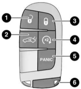
Your vehicle is equipped with a key fob which supports Passive Entry, Remote Keyless Entry (RKE), Keyless Enter-N-Go (if equipped), Remote Start (if equipped), and remote trunk release. The key fob allows you to lock or unlock the doors and trunk from distances up to approximately 66 ft (20 m). The key fob does not need to be pointed at the vehicle to activate the system. The key fob also contains an emergency key, which is stored in the rear of the key fob.
NOTE:
- The key fob's wireless signal may be blocked if the key fob is located next to a mobile phone, laptop, or other electronic device. This may result in poor performance.
- With ignition in the ON position and the vehicle moving at 2 mph (4 km/h), all RKE commands are disabled.
text_image
1 2 3 4 5 6 PANICA0204000072US
Key Fob
1 – Unlock
2 – Trunk Open
3 - Lock
4 – Remote Start
5-PANIC Button
6 - Emergency Key
In case the ignition switch does not change with the push of a button, the key fob may have a low or fully depleted battery. A low key fob battery can be verified by referring to the instrument cluster, which will display directions to follow page 298.
To Lock/Unlock The Doors And Trunk
Push and release the unlock button on the key fob once to unlock the driver's door, or twice within five seconds to unlock all the doors and the trunk. To lock all the doors and the trunk, push the lock button once.
When the doors are unlocked, the turn signals will flash and the illuminated entry system will be activated. When the doors are locked, the turn signals will flash and the horn will chirp.
NOTE:
- If the vehicle is unlocked by Passive Entry and no door is opened within 60 seconds, the vehicle will re-lock and the security system will arm (if equipped).
- If one or more doors are open, or the trunk is open, the doors will lock. The doors will unlock automatically if the key fob is left inside the passenger compartment, otherwise the doors will stay locked.
All doors can be programmed to unlock on the first push of the unlock button through Uconnect Settings → page 144.
NOTE:
When you use the key fob to open any door, the courtesy lights, overhead lights, and approach lighting in the outside mirrors (if equipped) will turn on ↩ page 49.
To Unlatch The Trunk
Push the trunk button on the key fob two times within five seconds to unlatch the trunk.
Replacing The Battery In The Key Fob
The recommended replacement battery is one CR2032 battery.
NOTE:
- Customers are recommended to use a battery obtained from Mopar. Aftermarket coin battery dimensions may not meet the original OEM coin battery dimensions.
- Perchlorate Material — special handling may apply. See www.dtsc.ca.gov/hazardouswaste/perchlorate for further information.
-
Do not touch the battery terminals that are on the back housing or the printed circuit board.
-
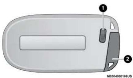
Remove the emergency key (2) by sliding the emergency key release (1) on the back of the key fob and pull the emergency key out with your other hand.
text_image
① ② M0304000166USEmergency Key Removal
1 – Emergency Key Release Button
2 – Emergency Key
14 GETTING TO KNOW YOUR VEHICLE
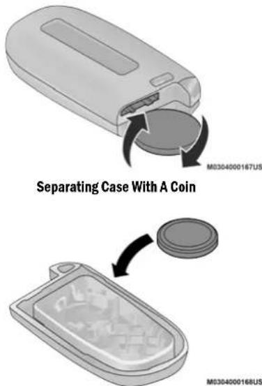
- Separate the key fob halves using a #2 flat blade screwdriver or a coin, and gently pry the two halves of the key fob apart. Make sure not to damage the seal during removal.
text_image
Separating Case With A Coin M0304000167US M0304000168USKey Fob Battery Replacement
- Remove the back cover to access and replace the battery. When replacing the battery, match the (+) sign on the battery to the (+) sign on the inside of the battery clip, located on the back cover. Avoid touching the new battery with your fingers. Skin oils may cause battery deterioration. If you touch a battery, clean it with rubbing alcohol.
- To assemble the key fob case, snap the two halves together.
Programming And Requesting Additional Key Fobs
Programming the key fob may be performed by an authorized dealer.
NOTE:
- Once a key fob is programmed to a vehicle, it cannot be re-purposed and reprogrammed to another vehicle.
- Only key fobs that are programmed to the vehicle electronics can be used to start and operate the vehicle. Once a key fob is programmed to a vehicle, it cannot be programmed to any other vehicle.
WARNING!
- Always remove the key fobs from the vehicle and lock all doors when leaving the vehicle unattended.
- For vehicles equipped with Keyless Enter-N-Go — Ignition, always remember to place the ignition in the OFF mode.
Duplication of key fobs may be performed at an authorized dealer. This procedure consists of programming a blank key fob to the vehicle electronics. A blank key fob is one that has never been programmed.
NOTE:
When having the Sentry Key Immobilizer system serviced, bring all vehicle keys with you to an authorized dealer.
SENTRY KEY
The Sentry Key Immobilizer system prevents unauthorized vehicle operation by disabling the engine. The system does not need to be armed or activated. Operation is automatic, regardless of whether the vehicle is locked or unlocked.
The system uses a key fob, keyless push button ignition and a Radio Frequency (RF) receiver to prevent unauthorized vehicle operation.
Therefore, only key fobs that are programmed to the vehicle can be used to start and operate the vehicle. The system cannot reprogram a key fob obtained from another vehicle.
After placing the ignition switch in the ON/RUN position, the vehicle security light will turn on for three seconds for a bulb check. If the light remains on after the bulb check, it indicates that there is a problem with the electronics. In addition, if the light begins to flash after the bulb check, it indicates that someone attempted to start the engine with an invalid key fob. In the event that a valid key fob is used to start the engine but there is an issue with the vehicle electronics, the engine will start and shut off after two seconds.
If the vehicle security light turns on during normal vehicle operation (vehicle running for longer than 10 seconds), it indicates that there is a fault in the electronics. Should this occur, have the vehicle serviced as soon as possible by an authorized dealer.
CAUTION!
The Sentry Key Immobilizer system is not compatible with some aftermarket remote starting systems. Use of these systems may result in vehicle starting problems and loss of security protection.
All of the key fobs provided with your new vehicle have been programmed to the vehicle electronics ▶ page 298.
IGNITION SWITCH
KEYLESS ENTER-N-GO — IGNITION
This feature allows the driver to operate the ignition switch with the push of a button as long as the key fob is in the passenger compartment.
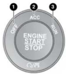
The START/STOP ignition button has several operating modes that are labeled and will illuminate when in position. These modes are OFF, ACC, ON/RUN, and START.
text_image
1 OFF 2 ACC RUN ENGINE START STOP O/8A0205000012US
START/STOP Ignition Button
1-OFF
2-ACC
3 - ON/RUN
The push button ignition can be placed in the following modes:
OFF
• The engine is stopped.
- Some electrical devices (e.g. central locking, alarm, etc.) are still available.
16 GETTING TO KNOW YOUR VEHICLE
ACC
- Engine is not started.
- Some electrical devices are available (e.g. power windows).
ON/RUN
- Driving position.
- All the electrical devices are available (e.g. climate controls, etc.).
START
- The engine will start (when foot is on the brake pedal).
NOTE:
If the ignition switch does not change the mode by pushing the button, the key fob may have a low or depleted battery. In this situation, a back up method can be used to operate the ignition switch. Put the nose side (side opposite of the emergency key) of the key fob against the START/STOP ignition button and push to operate the ignition switch.
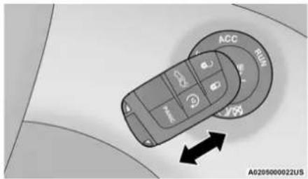
text_image
ACC RUN A0205000022USDepleted Key Fob Battery Procedure
WARNING!
- When exiting the vehicle, always remove the key fob from the vehicle and lock your vehicle.
- Never leave children alone in a vehicle, or with access to an unlocked vehicle.
- Allowing children to be in a vehicle unattended is dangerous for a number of reasons. A child or others could be seriously or fatally injured. Children should be warned not to touch the parking brake, brake pedal or the gear selector.
(Continued)
WARNING! (Continued)
- Do not leave the key fob in or near the vehicle, or in a location accessible to children, and do not leave the ignition of a vehicle equipped with Keyless Enter-N-Go in the ON/RUN mode. A child could operate power windows, other controls, or move the vehicle.
- Do not leave children or animals inside parked vehicles in hot weather. Interior heat build-up may cause serious injury or death.
CAUTION!
An unlocked vehicle is an invitation for thieves. Always remove key fob from the vehicle and lock all doors when leaving the vehicle unattended.
NOTE:
- When opening the driver's door with the ignition in ON/RUN (engine not running), a chime will sound to remind you to place the ignition in the OFF position. In addition to the chime, the message will display "Ignition Or Accessory On" in the cluster.
- For more information on proper engine starting procedures, see ➕ page 93.
REMOTE START — IF EQUIPPED

This system uses the key fob to start the engine conveniently from outside the vehicle while still maintaining security.
Remote start is used to defrost windows in cold weather, and to reach a comfortable climate in all ambient conditions before the driver enters the vehicle.
NOTE:
Obstructions between the vehicle and key fob may reduce this range ➔ page 298.
WARNING!
- Do not start or run an engine in a closed garage or confined area. Exhaust gas contains Carbon Monoxide (CO) which is odorless and colorless. Carbon Monoxide is poisonous and can cause serious injury or death when inhaled.
- Keep key fobs away from children. Operation of the Remote Start system, windows, door locks or other controls could cause serious injury or death.
How To Use Remote Start
Push and release the remote start button on the key fob twice within five seconds. The vehicle doors will lock, the parking lights will flash, and the horn will chirp twice (if programmed through the Uconnect settings). Then, the engine will start, and the vehicle will remain in the Remote Start mode for a 15 minute cycle. Pushing the remote start button a third time shuts the engine off.
To drive the vehicle, push the unlock button, and with a valid Keyless Enter-N-Go key fob in the vehicle, press the brake pedal and place the ignition in the ON/RUN position.
NOTE:
- With Remote Start, the engine will only run for 15 minutes.
- If an engine fault is present or fuel level is low, the vehicle will start and then shut down in 10 seconds.
- The park lamps will turn on and remain on during Remote Start mode.
- For security, power window operation is disabled when the vehicle is in the Remote Start mode.
- Remote Start can only be used twice. The ignition must be placed in the ON/RUN position before the Remote Start sequence can be repeated for a third cycle.
All of the following conditions must be met before the engine will remote start:
• Gear selector in PARK
- Doors closed
- Hood closed
- Trunk closed
- Hazard switch off
- Brake switch inactive (brake pedal not pushed)
● Battery at an acceptable charge level
- Check engine light shall not be present
- PANIC button not pushed
- System not disabled from previous remote start event
● Vehicle Security system indicator flashing
- Ignition in OFF position
● Fuel level meets minimum requirement
- Vehicle Security system is not signaling an intrusion
- Malfunction Indicator Light is not illuminated
WARNING!
- Do not start or run an engine in a closed garage or confined area. Exhaust gas contains Carbon Monoxide (CO) which is odorless and colorless. Carbon Monoxide is poisonous and can cause serious injury or death when inhaled.
- Keep key fobs away from children. Operation of the Remote Start system, windows, door locks or other controls could cause serious injury or death.
To Exit Remote Start Mode
To drive the vehicle after starting the Remote Start system, either push and release the unlock button on the key fob to unlock the doors, or unlock the vehicle using Keyless Enter-N-Go — Passive Entry via the door handles, and disarm the Vehicle Security system (if equipped). Then, prior to the end of the 15 minute cycle, push and release the START/STOP ignition button.
The Remote Start system will turn the engine off with another push and release of the Remote Start button on the key fob, or if the engine is allowed to run for the entire 15 minute cycle.
Once the ignition is placed in the ON/RUN position, the climate controls will resume the previously set operations (temperature, blower control, etc.).
NOTE:
- To avoid unintentional shutdowns, the system will disable for two seconds after receiving a valid Remote Start request.
- For vehicles equipped with the Keyless Enter-N-Go — Passive Entry feature, the message “Remote Start Active — Push Start Button” will display in the instrument cluster display until you push the START/STOP ignition button.
REMOTE START FRONT DEFROST ACTIVATION — IF EQUIPPED
When remote start is active, and the outside ambient temperature is 40^ F ( 4.5^ C) or below, the system will automatically activate front defrost for 15 minutes or less. The time is dependent on the ambient temperature. Once the timer expires, the system will automatically adjust the settings depending on ambient conditions. See “Remote Start Comfort Systems — If Equipped” in the next section for detailed operation.
REMOTE START COMFORT SYSTEMS — IF EQUIPPED
When remote start is activated, the front and rear defrost will automatically turn on in cold weather. The heated steering wheel and driver heated seat feature will turn on if selected in the comfort menu screen within Uconnect Settings ➤ page 144. In warm weather, the driver vented seat feature will turn on when remote start is activated, if programmed in the Comfort menu screen. The vehicle will adjust the climate control settings depending on the outside ambient temperature.
Automatic Temperature Control (ATC) — If Equipped
The climate controls will be automatically adjusted to the optimal temperature and mode settings depending on the outside ambient temperature. This will occur until the ignition is placed in the ON/RUN position where the climate controls will resume their previous settings.
Manual Temperature Control (MTC) — If Equipped
- In ambient temperatures at 40^ F ( 4.5^ C) or below, the climate settings will default to maximum heat, with fresh air entering the cabin. If the front defrost timer expires, the vehicle will enter Mix Mode.
- In ambient temperatures from 40^ F ( 4.5^ C) to 78^ F ( 26^ C), the climate settings will be based on the last settings selected by the driver.
- In ambient temperatures at 78^ F ( 26^ C) or above, the climate settings will default to MAX A/C, Bi-Level Mode, with Recirculation on.
For more information on ATC, MTC, and climate control settings, see ➤ page 53.
NOTE:
These features will stay on through the duration of remote start until the ignition is placed in the ON/RUN position. The climate control settings will change if manually adjusted by the driver while the vehicle is in remote start mode, and exit automatic override. This includes the OFF button on the climate controls, which will turn the system off.
REMOTE START CANCEL MESSAGE
The following messages will display in the instrument cluster display if the vehicle fails to remote start or exits remote start prematurely:
- Remote Start Aborted — Door Open
- Remote Start Aborted — Hood Open
- Remote Start Aborted — Fuel Low
- Remote Start Aborted — Trunk Open
- Remote Start Disabled — Start Vehicle To Reset
- Remote Start Aborted — Too Cold
- Remote Start Aborted — Time Expired
The instrument cluster display message stays active until the ignition is placed in the ON/RUN position
VEHICLE SECURITY SYSTEM — IF EQUIPPED
The Vehicle Security system monitors the vehicle doors, hood, trunk, and the Keyless Enter-N-Go — Ignition for unauthorized operation. While the Vehicle Security system is armed, interior switches for door locks and trunk release are disabled. If something triggers the alarm, the Vehicle Security system will provide the following audible and visible signals:
- The horn will pulse
• The turn signals will flash - The Vehicle Security Light in the instrument cluster will flash
To Arm The System
Follow these steps to arm the Vehicle Security system:
- Make sure the vehicle's ignition is placed in the OFF position.
- Perform one of the following methods to lock the vehicle:
- Push lock on the interior power door lock switch with the driver and/or passenger door open.
- Push the lock button on the exterior Passive Entry door handle with a valid key fob available in the same exterior zone → page 22.
-
Push the lock button on the key fob.
-
If any doors are open, close them.
To Disarm The System
The Vehicle Security system can be disarmed using any of the following methods:
- Push the unlock button on the key fob.
- Grab the Passive Entry door handle to unlock the door ↩ page 22.
- Cycle the ignition out of the OFF position to disarm the system.
NOTE:
- The driver's door key cylinder and the trunk button on the key fob cannot arm or disarm the Vehicle Security system. Use of the door key cylinder when the system is armed will sound the alarm when the door is opened.
- If Passive Entry (if equipped) is used to unlock the trunk, the Vehicle Security system is disarmed and the rest of the vehicle doors will remain locked unless “Unlock All Doors 1st Press” is selected in the Passive Entry settings.
- When the Vehicle Security system is armed, the interior power door lock switches will not unlock the doors.
The Vehicle Security system is designed to protect your vehicle. However, you can create conditions where the system will give you a false alarm. If one of the previously described arming sequences has occurred, the Vehicle Security system will arm, regardless of whether you are in the vehicle or not. If you remain in the vehicle and open a door, the alarm will sound. If this occurs, disarm the Vehicle Security system.
If the Vehicle Security system is armed and the battery becomes disconnected, the Vehicle Security system will remain armed when the battery is reconnected; the exterior lights will flash, and the horn will sound. If this occurs, disarm the Vehicle Security system.
REARMING OF THE SYSTEM
If something triggers the alarm, and no action is taken to disarm it, the Vehicle Security system will turn the horn off after 29 seconds, five seconds between cycles, and up to eight cycles if the trigger remains active. The Vehicle Security system will then rearm itself.
SECURITY SYSTEM MANUAL OVERRIDE
The Vehicle Security system will not arm if you lock the doors using the manual door lock.
TAMPER ALERT
If something has triggered the Vehicle Security system in your absence, the horn will sound three times and the exterior lights will blink three times when you disarm the Vehicle Security system.
DOORS
MANUAL DOOR LOCKS
The power door locks can be manually locked from inside the vehicle by using the door lock knob. To lock each door, push the door lock knob on each door trim panel downward. To unlock the front doors, pull the inside door
handle to the first detent. To unlock the rear doors, pull the door lock knob on the door trim panel upward. If the lock knob is down when the door is closed, the door will lock. Make sure the key fob is not inside the vehicle before closing the door.
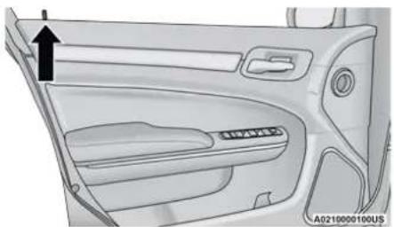
natural_image
Interior view of a car dashboard with no visible text or symbols on the panel itselfDoor Lock Knob
NOTE:
Manually locking the vehicle will not arm the Vehicle Security system.
WARNING!
- For personal security and safety in the event of a collision, lock the vehicle doors before you drive as well as when you park and leave the vehicle.
- When exiting the vehicle, always make sure the keyless ignition node is in the OFF mode, remove the key fob from the vehicle and lock your vehicle.
- Never leave children alone in a vehicle, or with access to an unlocked vehicle. Allowing children to be in a vehicle unattended is dangerous for a number of reasons. A child or others could be seriously or fatally injured. Children should be warned not to touch the parking brake, brake pedal or the gear selector.
- Do not leave the key fob in or near the vehicle, or in a location accessible to children, and do not leave the ignition of a vehicle equipped with Keyless Enter-N-Go in the ACC or ON/RUN mode. A child could operate power windows, other controls, or move the vehicle.
Power Door Locks
The power door lock switches are located on each front door panel. Push the switch to lock or unlock the doors.
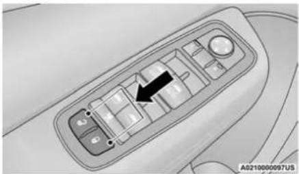
natural_image
Interior view of a car dashboard with control panel and directional arrow (no text or symbols)Power Door Lock Switches
The driver's door will unlock automatically if the keys are found inside the vehicle when the door lock button on the front door panel is used to lock the door. This will occur for two attempts. Upon the third attempt, the doors will lock even if the key is inside.
NOTE:
If the key fob is located next to a mobile phone, laptop, or other electronic device, the wireless signal may get blocked, and the driver's door may not unlock automatically.
If the door lock switch is pushed while the ignition is in ACC or ON/RUN and the driver's door is open, the doors will not lock.
If a rear door is locked, it cannot be opened from inside the vehicle without first unlocking the door. The door may be unlocked manually by raising the lock knob.
KEYLESS ENTER-N-GO — PASSIVE ENTRY
The Passive Entry system is an enhancement to the vehicle's key fob and a feature of Keyless Enter-N-Go. This feature allows you to lock and unlock the vehicle's door(s) without having to push the key fob lock or unlock buttons.
NOTE:
- Passive Entry may be programmed on/off through Uconnect Settings ▶ page 144.
- The key fob may not be able to be detected by the vehicle Passive Entry system if it is located next to a mobile phone, laptop or other electronic device; these devices may block the key fob's wireless signal and prevent the Passive Entry handle from locking/unlocking the vehicle.
- Passive Entry Unlock initiates illuminated approach (low beams, license plate lamp, position lamps) for whichever time duration is set between 0, 30, 60 or 90 seconds. Passive Entry Unlock also initiates two flashes of the turn signal lamps.
- If wearing gloves, or if it has been raining/snowing on the Passive Entry door handle, the unlock sensitivity can be affected, resulting in a slower response time.
- If the vehicle is unlocked by Passive Entry and no door is opened within 60 seconds, the vehicle will re-lock and (if equipped) will arm the Vehicle Security system.
To Unlock From The Driver Or Passenger Side
With a Passive Entry key fob within 5 ft (1.5 m) of the door handle, grab the handle to unlock the vehicle. Grabbing the driver's door handle will unlock the driver door automatically. Grabbing the passenger door handle will unlock both doors automatically.
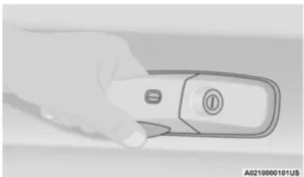
natural_image
Hand holding a remote control device with a button labeled (no visible text or symbols on the device itself)Grab The Door Handle To Unlock
NOTE:
- If "Unlock All Doors 1st Press" is programmed, all doors will unlock when you grab hold of the front driver's door handle. To select between "Unlock Driver Door 1st Press" and "Unlock All Doors 1st Press" through Uconnect Settings → page 144.
- All doors will unlock when the front passenger door handle is grabbed regardless of the driver's door unlock preference setting.
Frequency Operated Button Integrated Key (FOBIK-Safe)
To minimize the possibility of unintentionally locking a Passive Entry key fob inside your vehicle, the Passive Entry system is equipped with an automatic door unlock feature which will function if the ignition is in the OFF position.
There are three situations that trigger a FOBIK-Safe search in any Passive Entry vehicle.
- A lock request is made by a valid Passive Entry key fob while a door is open.
- A lock request is made by the Passive Entry door handle while a door is open.
- A lock request is made by the door panel switch while the door is open.
When any of these situations occur, after all open doors are shut, the FOBIK-Safe search will be executed. If it finds a Passive Entry key fob inside the vehicle, the vehicle will unlock and alert the customer.
24 GETTING TO KNOW YOUR VEHICLE
NOTE:
The vehicle will only unlock the doors when a valid Passive Entry key fob is detected inside the vehicle. The vehicle will not unlock the doors when any of the following conditions are true:
- The doors are manually locked using the door lock knobs.
- Three attempts are made to lock the doors using the door panel switch and then the doors are closed.
- There is a valid Passive Entry key fob outside the vehicle and within 5 ft (1.5 m) of either Passive Entry door handle.
To Lock The Vehicle's Doors And Trunk
With one of the vehicle's Passive Entry key fobs within 5 ft (1.5 m) of either door handle, pushing the Passive Entry lock button will lock both doors.
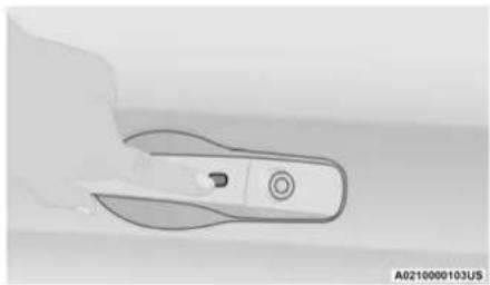
natural_image
Close-up of a hand holding a white plastic clip or clip device (no visible text or symbols)Push The Door Handle Button To Lock
NOTE:
Do NOT grab the door handle when pushing the door handle lock button. This could unlock the door(s).
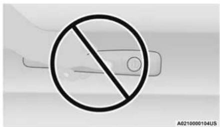
text_image
A0210000104USDo NOT Grab The Door Handle When Locking
NOTE:
- After pushing the door handle button, you must wait two seconds before you can lock or unlock the doors, using either Passive Entry door handle. This is done to allow you to check if the vehicle is locked by pulling the door handle, without the vehicle unlocking.
- The Passive Entry system will not operate if the key fob battery is depleted.
To Unlock/Enter The Trunk
With a valid Passive Entry key fob within 5 ft (1.5 m) of the deck lid, push the button on the right side of the Center High Mounted Stop Light (CHMSL), which is located on the deck lid.
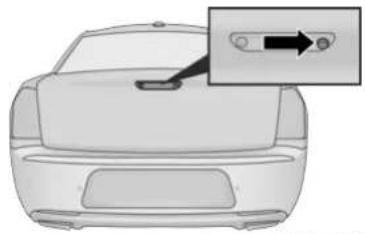
natural_image
Top-down view of a car showing the side panel and a close-up of the dashboard (no text or symbols visible)Trunk Passive Entry Button
NOTE:
If you inadvertently leave your vehicle's Passive Entry key fob in the trunk and try to close the deck lid, the deck lid will automatically unlatch, unless another one of the vehicle's Passive Entry key fobs is outside the vehicle and within 5 ft (1.5 m) of the deck lid ➞ page 298.
AUTOMATIC UNLOCK DOORS ON EXIT
The doors will unlock automatically on vehicles with power door locks if:
- The Automatic Unlock Doors On Exit feature is enabled within Uconnect Settings → page 144.
- The transmission gear selector was not in PARK, then is placed in PARK.
- The driver door is opened.
- The doors were not previously unlocked.
NOTE:
Use the Automatic Unlock Doors On Exit feature in accordance with local laws.
AUTOMATIC DOOR LOCKS — IF EQUIPPED
The auto door lock feature default condition is enabled. When enabled, the door locks will lock automatically when the vehicle's speed exceeds 15 mph (24 km/h). The auto door lock feature can be enabled or disabled by an authorized dealer per written request of the customer. Please see an authorized dealer for service.
CHILD-PROTECTION DOOR LOCK SYSTEM — REAR DOORS
To provide a safer environment for small children riding in the rear seats, the rear doors are equipped with Child-Protection Door Lock system.
To use the system, open each rear door, use a flat blade screwdriver (or emergency key) and rotate the dial to the lock or unlock position.
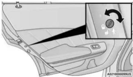
natural_image
Interior view of a car showing the dashboard and seat area with a directional control panel (no text or symbols visible)Child-Protection Door Lock Function
NOTE:
- When the Child-Protection Door Lock system is engaged, the door can be opened only by using the outside door handle even though the inside door lock is in the unlocked position.
- After disengaging the Child-Protection Door Lock system, always test the door from the inside to make certain it is in the unlocked position.
- After engaging the Child-Protection Door Lock system, always test the door from the inside to make certain it is in the locked position.
- For emergency exit with the system engaged, pull up on the door lock knob (unlocked position), roll down the window, and open the door with the outside door handle.
WARNING!
Avoid trapping anyone in a vehicle in a collision. Remember that the rear doors can only be opened from the outside with the Child-Protection locks are engaged (locked).
NOTE:
Always use this device when carrying children. After engaging the child lock on both rear doors, check for effective engagement by trying to open a door with the internal handle. Once the Child-Protection Door Lock system is engaged, it is impossible to open the doors from inside the vehicle. Before getting out of the vehicle, be sure to check that there is no one left inside.
STEERING WHEEL
MANUAL TILT/TELESCOPING STEERING COLUMN — IF EQUIPPED
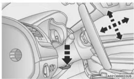
This feature allows you to tilt the steering column upward or downward. It also allows you to lengthen or shorten the steering column. The tilt/telescoping control is located below the steering wheel at the end of the steering column.
natural_image
Interior view of a car showing steering wheel, dashboard, and directional arrows (no text or symbols)Manual Tilt/Telescoping Control
To unlock the steering column, push the control downward (toward the floor). To tilt the steering column, move the steering wheel upward or downward as desired. To lengthen or shorten the steering column, pull the steering wheel outward or push it inward as desired. To lock the steering column in position, push the control upward until fully engaged.
WARNING!
Do not adjust the steering column while driving. Adjusting the steering column while driving or driving with the steering column unlocked, could cause the driver to lose control of the vehicle. Failure to follow this warning may result in serious injury or death.
POWER TILT/TELESCOPING STEERING COLUMN — IF EQUIPPED
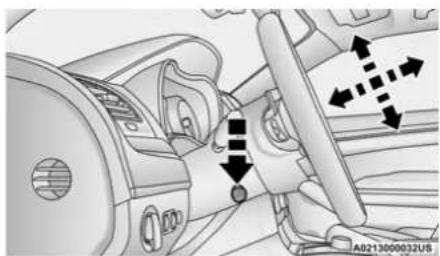
This feature allows you to tilt the steering column upward or downward. It also allows you to lengthen or shorten the steering column. The power tilt/telescoping steering column control is located below the multifunction lever on the steering column.
natural_image
Interior view of a car dashboard and steering wheel (no text or symbols visible)Power Tilt/Telescoping Steering Control
Use the four-way control to adjust the steering column.
NOTE:
For vehicles equipped with Driver Memory Settings ↩ page 29, you can use your key fob or the memory switch on the driver's door trim panel to return the tilt/telescopic steering column to saved positions.
WARNING!
Do not adjust the steering column while driving. Adjusting the steering column while driving or driving with the steering column unlocked, could cause the driver to lose control of the vehicle. Failure to follow this warning may result in serious injury or death.
HEATED STEERING WHEEL — IF EQUIPPED
The steering wheel contains a heating element that helps warm your hands in cold weather. The heated steering wheel has only one temperature setting. Once the heated steering wheel has been turned on, it will stay on for an average of 80 minutes before automatically shutting off. This time will vary based on environmental temperatures. The heated steering wheel can shut off early or may not turn on when the steering wheel is already warm.
The heated steering wheel control button is located within the Uconnect system. You can gain access to the control button through the climate or controls screen.
- Press the heated steering wheel button once to turn the heating element on.
- Press the heated steering wheel button—a second time to turn the heating element off.
NOTE:
The engine must be running for the heated steering wheel to operate.
For information on use with the Remote Start system, see ➕ page 19.
WARNING!
- Persons who are unable to feel pain to the skin because of advanced age, chronic illness, diabetes, spinal cord injury, medication, alcohol use, exhaustion, or other physical conditions must exercise care when using the steering wheel heater. It may cause burns even at low temperatures, especially if used for long periods.
- Do not place anything on the steering wheel that insulates against heat, such as a blanket or steering wheel covers of any type and material. This may cause the steering wheel heater to overheat.
UCONNECT VOICE RECOGNITION QUICK TIPS
INTRODUCING UCONNECT
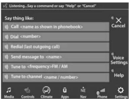
Start using Uconnect Voice Recognition (VR) with these helpful quick tips. It provides the key Voice Commands and tips you need to know to control your Uconnect system.
NOTE:
The NAV icon on the bottom bar, or in the Apps menus, of your touchscreen, shows you have the Uconnect 4C NAV system. If not, you have a Uconnect 4C system.
text_image
Listening...Say a command or say "Help" or "Cancel" Say thing like: CallVoice Recognition
BASIC VOICE COMMANDS
The basic Voice Commands below can be given at any point while using your Uconnect system.
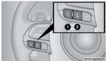
Push the VR button ⓍAfter the beep, say:
- "Cancel" to stop a current voice session
- "Help" to hear a list of suggested Voice Commands
- "Repeat" to listen to the system prompts again
Notice the visual cues that inform you of your voice recognition system's status. Cues appear on the touchscreen.
GET STARTED
The VR button is used to activate/deactivate your VR system.
Helpful hints for using VR:
- Reduce background noise. Wind and passenger conversations are examples of noise that may impact recognition.
-
Speak clearly at a normal pace and volume while facing straight ahead.
-
Each time you give a Voice Command, you must first push the VR button, wait until after the beep, then say your Voice Command.
- You can interrupt the help message or system prompts by pushing the VR button and saying a Voice Command from the current category.
text_image
M1001000800USUconnect Voice Command Buttons
1 — Push To Start Or Answer A Phone Call And Send Or Receive A Text
2 — Push The VR Button To Begin Radio, Media, And Climate Functions
ADDITIONAL INFORMATION
© 2020 FCA US LLC. All rights reserved. Mopar and Uconnect are registered trademarks and Mopar Owner Connect is a trademark of FCA US LLC. Android™ is a trademark of Google Inc. SiriusXM® and all related marks and logos are trademarks of SiriusXM® Radio Inc.
Uconnect System Support:
- US residents visit www.DriveUconnect.com or call: 1-877-855-8400 (24 hours a day 7 days a week)
- Canadian residents visit www.DriveUconnect.ca or call: 1-800-465-2001 (English) or 1-800-387-9983 (French)
SiriusXM Guardian™ services support:
- US residents visitwww.driveuconnect.com/sirius-xm-guardian or call: 1-844-796-4827
- Canadian residents visitwww.siriusxm.ca/guardian-v1/ or call: 1-877-324-9091
DRIVER MEMORY SETTINGS — IF EQUIPPED
This feature allows the driver to save up to two different memory profiles for easy recall through a memory switch. Each memory profile saves desired position settings for the following features:
- Driver seat
- Easy Entry/Exit seat operation (on/off) (if equipped)
- Side mirrors
● Power tilt and telescopic steering column (if equipped) - A set of desired radio station presets
NOTE:
- Your vehicle is equipped with two key fobs, each can be linked to either memory position 1 or 2.
- Be sure to program the radio presets prior to programming the memory settings.
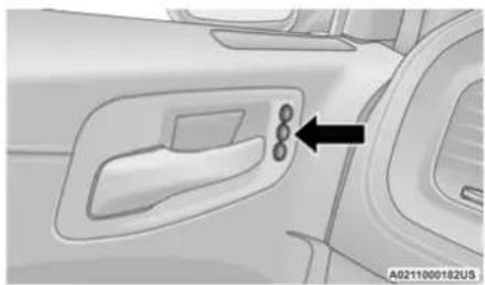
The memory settings switch is located on the driver's door trim panel. The switch consists of three buttons:
- The set (S) button, which is used to activate the memory save function.
- The (1) and (2) buttons which are used to recall either of two saved memory profiles.
natural_image
Interior view of a car showing the door, vent, and control panel (no text or symbols visible)Memory Switch
PROGRAMMING THE MEMORY FEATURE
To create a new memory profile, perform the following:
NOTE:
Saving a new memory profile will erase the selected profile from memory.
30 GETTING TO KNOW YOUR VEHICLE
- Place the vehicle's ignition in the ON/RUN position (do not start the engine).
- Adjust all memory profile settings to desired preferences (i.e., seat, side mirror, power tilt and telescopic steering column [if equipped], and radio station presets).
- Push and release the set (S) button on the memory switch, and then push the desired memory button (1 or 2) within five seconds. The instrument cluster display will display which memory position has been set.
NOTE:
Memory profiles can be set without the vehicle in PARK, but the vehicle must be in PARK to recall a memory profile.
LINKING AND UNLINKING THE KEY FOB TO MEMORY
Your key fobs can be programmed to recall one of two saved memory profiles by pushing the unlock button on the key fob.
NOTE:
Before programming your key fobs you must select the "Memory Linked To Fob" feature through the Uconnect system ▼ page 144. To program your key fobs, perform the following:
- Place the vehicle's ignition in the OFF position.
- Select a desired memory profile, 1 or 2.
- Once the profile has been recalled, push and release the set (S) button on the memory switch.
- Within five seconds, push and release button (1) or (2) accordingly. "Memory Profile Set" (1 or 2) will display in the instrument cluster.
- Push and release the lock button on the key fob within 10 seconds.
NOTE:
Your key fob can be unlinked from your memory settings by pushing the set (S) button, followed by pushing the unlock button on the key fob within 10 seconds.
MEMORY POSITION RECALL
NOTE:
If a recall is attempted when the vehicle is not in PARK, a message will be displayed in the instrument cluster display. To recall the memory settings for driver one or two, push the desired memory button number (1 or 2) or the unlock button on the key fob linked to the desired memory position.
A recall can be canceled by pushing any of the memory buttons (S, 1, or 2) during a recall. When a recall is canceled, the driver seat will stop moving. A delay of one second will occur before another recall can be selected.
SEATS
Seats are a part of the Occupant Restraint System of the vehicle.
WARNING!
- It is dangerous to ride in a cargo area, inside or outside of a vehicle. In a collision, people riding in these areas are more likely to be seriously injured or killed.
- Do not allow people to ride in any area of your vehicle that is not equipped with seats and seat belts. In a collision, people riding in these areas are more likely to be seriously injured or killed.
- Be sure everyone in your vehicle is in a seat and using a seat belt properly.
MANUAL ADJUSTMENT (REAR SEATS)
Folding Rear Seat
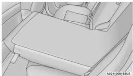
The rear seatbacks can be folded forward to provide an additional storage area. To fold the rear seatback, pull on the loops located on the upper seatback.
NOTE:
These loops can be tucked away when not in use.

natural_image
Interior view of a car showing seatbelt and side panel (no text or symbols)Rear Seatback Loop
After releasing the seatback, it can be folded forward.
natural_image
Interior view of a car showing the dashboard and seat area (no text or symbols visible)Folded Rear Seatback
NOTE:
You may experience deformation in the seat cushion from the seat belt buckles if the seats are left folded for an extended period of time. This is normal and by simply opening the seats to the open position, over time the seat cushion will return to its normal shape.
When the seatback is folded to the upright position, make sure it is latched by strongly pulling on the top of the seatback above the seat strap.
WARNING!
- Be certain that the seatback is securely locked into position. If the seatback is not securely locked into position, the seat will not provide the proper stability for child seats and/or passengers. An improperly latched seat could cause serious injury.
- The cargo area in the rear of the vehicle (with the rear seatbacks in the locked-up or folded down position) should not be used as a play area by children when the vehicle is in motion. They could be seriously injured in a collision. Children should be seated and using the proper restraint system.
POWER ADJUSTMENT (FRONT SEATS)
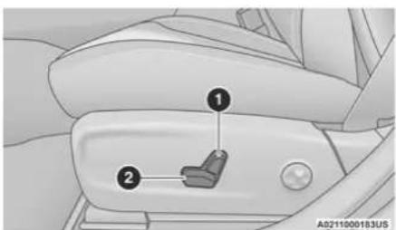
Your vehicle may be equipped with eight-way power driver and front passenger seats. The power seat switches are located on the outboard side of the seat. There are two switches that control the movement of the seat cushion and the seatback.
text_image
Diagram of car seatbelt with numbered labels pointing to key componentsPower Seat Switches
1 - Seatback Control (If Equipped)
2 - Seat Control
WARNING!
- Adjusting a seat while driving may be dangerous. Moving a seat while driving could result in loss of control which could cause a collision and serious injury or death.
- Seats should be adjusted before fastening the seat belts and while the vehicle is parked. Serious injury or death could result from a poorly adjusted seat belt.
- Do not ride with the seatback reclined so that the shoulder belt is no longer resting against your chest. In a collision you could slide under the seat belt, which could result in serious injury or death.
CAUTION!
Do not place any article under a power seat or impede its ability to move as it may cause damage to the seat controls. Seat travel may become limited if movement is stopped by an obstruction in the seat's path.
Adjusting The Seat Forward Or Rearward
The seat can be adjusted both forward and rearward by using the power seat switch. The seat will move in the direction of the switch. Release the switch when the desired position has been reached.
Adjusting The Seat Up Or Down
The height of the seats can be adjusted up or down by using the power seat switch. The seat will move in the direction of the switch. Release the switch when the desired position has been reached.
Tilting The Seat Up Or Down
The angle of the seat cushion can be adjusted up or down using the power seat switch. The front of the seat cushion will move in the direction of the switch. Release the switch when the desired position has been reached.
Reclining The Seatback
The angle of the seatback can be adjusted forward or rearward by using the power seat switch. The seat will move in the direction of the switch. Release the switch when the desired position is reached.
WARNING!
- Adjusting a seat while driving may be dangerous. Moving a seat while driving could result in loss of control which could cause a collision and serious injury or death.
- Seats should be adjusted before fastening the seat belts and while the vehicle is parked. Serious injury or death could result from a poorly adjusted seat belt.
- Do not ride with the seatback reclined so that the shoulder belt is no longer resting against your chest. In a collision you could slide under the seat belt, which could result in serious injury or death.
CAUTION!
Do not place any article under a power seat or impede its ability to move as it may cause damage to the seat controls. Seat travel may become limited if movement is stopped by an obstruction in the seat's path.
Power Lumbar — If Equipped
Vehicles equipped with power driver or passenger seats may also be equipped with power lumbar. The power lumbar switch is located on the outboard side of the power seat. Push the switch forward to increase the lumbar support. Push the switch rearward to decrease the lumbar support. Pushing upward or downward on the switch will raise and lower the position of the support.

natural_image
Interior view of a car seat with a circular button and a black arrow pointing to it (no text or symbols visible)Power Lumbar Switch
Easy Entry/Exit Seat — If Equipped
This feature provides automatic driver seat positioning to enhance driver mobility when entering and exiting the vehicle.
The distance the driver seat moves depends on where you have the driver seat positioned when you place the vehicle's ignition in the OFF position.
- When you place the vehicle's ignition in the OFF position, the driver seat will move about 2.4 inches (60 mm) rearward if the driver seat position is greater than or equal to 2.7 inches (67.7 mm) forward of the rear stop. The seat will return to its previously set position when you place the vehicle's ignition in the ACC or RUN position.
- The Easy Entry/Easy Exit feature is disabled when the driver seat position is less than 0.9 of an inch (22.7 mm) forward of the rear stop. At this position, there is no benefit to the driver by moving the seat for Easy Exit or Easy Entry.
When enabled in Uconnect Settings, Easy Entry and Easy Exit positions are stored in each memory setting profile → page 29.
NOTE:
The Easy Entry/Exit feature is enabled or disabled through the programmable features in the Uconnect system ➤ page 144.
HEATED SEATS — IF EQUIPPED
On some models, the front and rear seats may be equipped with heaters located in the seat cushions and seat backs.
WARNING!
- Persons who are unable to feel pain to the skin because of advanced age, chronic illness, diabetes, spinal cord injury, medication, alcohol use, exhaustion or other physical condition must exercise care when using the seat heater. It may cause burns even at low temperatures, especially if used for long periods of time.
(Continued)
WARNING! (Continued)
- Do not place anything on the seat or seat-back that insulates against heat, such as a blanket or cushion. This may cause the seat heater to overheat. Sitting in a seat that has been overheated could cause serious burns due to the increased surface temperature of the seat.
Front Heated Seats
The front heated seat control buttons are located within the climate or controls screen of the touchscreen.
You can choose from HI, LO, or OFF heat settings. The indicator arrows in touchscreen buttons indicate the level of heat in use. Two indicator arrows will illuminate for HI, and one for LO. Turning the heating elements off will return the user to the radio screen.
- Press the heated seat button once to turn the HI setting on.
- Press the heated seat button—a second time to turn the LO setting on.
- Press the heated seat button—a third time to turn the heating elements off.
If the HI-level setting is selected, the system will automatically switch to LO-level after approximately 60 minutes of continuous operation. At that time, the display will change from HI to LO, indicating the change. The LO-level setting will turn off automatically after approximately 45 minutes.
NOTE:
- Once a heat setting is selected, heat will be felt within two to five minutes.
- The engine must be running for the heated seats to operate.
For information on use with the Remote Start system, see ➕ page 19.
WARNING!
- Persons who are unable to feel pain to the skin because of advanced age, chronic illness, diabetes, spinal cord injury, medication, alcohol use, exhaustion or other physical condition must exercise care when using the seat heater. It may cause burns even at low temperatures, especially if used for long periods of time.
- Do not place anything on the seat or seat-back that insulates against heat, such as a blanket or cushion. This may cause the seat heater to overheat. Sitting in a seat that has been overheated could cause serious burns due to the increased surface temperature of the seat.
Rear Heated Seats — If Equipped
On some models, the two rear outboard seats may be equipped with heated seats. There are two heated seat switches that allow the rear passengers to operate the seats independently. The heated seat switches for each heater are located on the rear of the center console. You can choose from HI, LO, or OFF heat settings. Amber indicator lights in each switch indicate the level of heat in use. Two indicator lights will illuminate for HI, one for LO and none for OFF.
- Push the heated seat button/once to turn the HI setting on.
- Push the heated seat button, a second time to turn the LO setting on.
- Push the heated seat button—a third time to turn the heating elements off.
When the HI-level setting is selected, the heater will provide a boosted heat level during the first four minutes of operation. Then, the heat output will drop to the normal HI-level. If the HI-level setting is selected, the system will automatically switch to LO-level after approximately 60 minutes of continuous operation. At that time, the number of indicator lights changes from two to one, indicating the change. The LO-level setting will turn off automatically after approximately 45 minutes.
NOTE:
- Once a heat setting is selected, heat will be felt within two to five minutes.
- The engine must be running for the heated seats to operate.
WARNING!
- Persons who are unable to feel pain to the skin because of advanced age, chronic illness, diabetes, spinal cord injury, medication, alcohol use, exhaustion or other physical condition must exercise care when using the seat heater. It may cause burns even at low temperatures, especially if used for long periods of time.
- Do not place anything on the seat or seat-back that insulates against heat, such as a blanket or cushion. This may cause the seat heater to overheat. Sitting in a seat that has been overheated could cause serious burns due to the increased surface temperature of the seat.
FRONT VENTILATED SEATS — IF EQUIPPED
The ventilated seats are equipped with fans that can be controlled through the climate and control screen in the Uconnect system. The fans operate at two speeds, HI and LO.
- Press the ventilated seat button once to choose HI.
- Press the ventilated seat button a second time to choose LO.
- Press the ventilated seat button a third time to turn the ventilated seat off.
NOTE:
The engine must be running for the ventilated seats to operate.
For information on use with the Remote Start system, see ↩ page 19.
HEAD RESTRAINTS
Head restraints are designed to reduce the risk of injury by restricting head movement in the event of a rear impact. Head restraints should be adjusted so that the top of the head restraint is located above the top of your ear.
WARNING!
- All occupants, including the driver, should not operate a vehicle or sit in a vehicle's seat until the head restraints are placed in their proper positions in order to minimize the risk of neck injury in the event of a crash.
- Head restraints should never be adjusted while the vehicle is in motion. Driving a vehicle with the head restraints improperly adjusted or removed could cause serious injury or death in the event of a collision.
NOTE:
Do not reverse the head restraints (making the rear of the head restraint face forward) in an attempt to gain additional clearance to the back of your head.
Reactive Head Restraints — Front Seats
The front driver and passenger seats are equipped with Reactive Head Restraints (RHR). In the event of a rear impact, the RHR will automatically extend forward minimizing the gap between the back of the occupant's head and the RHR.
The RHR will automatically return to their normal position following a rear impact. If the RHR do not return to their normal position, see an authorized dealer immediately.
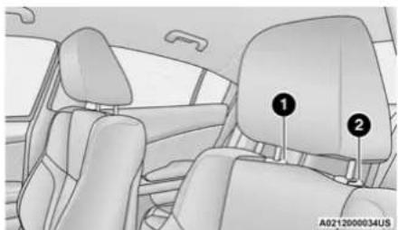
To raise the head restraint, pull upward on the head restraint. To lower the head restraint, push the adjustment button located at the base of the head restraint and push downward on the head restraint.
natural_image
Interior view of a car showing the front seat, rear seats, and dashboard (no text or symbols visible)Front Head Restraint
1 - Release Button
2 - Adjustment Button
WARNING!
- A loose head restraint thrown forward in a collision or hard stop could cause serious injury or death to occupants of the vehicle. Always securely stow removed head restraints in a location outside the occupant compartment.
- ALL the head restraints MUST be re-installed in the vehicle to properly protect the occupants. Follow the re-installation instructions above prior to operating the vehicle or occupying a seat.
- Do not place items over the top of the Reactive Head Restraint, such as coats, seat covers or portable DVD players. These items may interfere with the operation of the Reactive Head Restraint in the event of a collision and could result in serious injury or death.
Rear Head Restraints
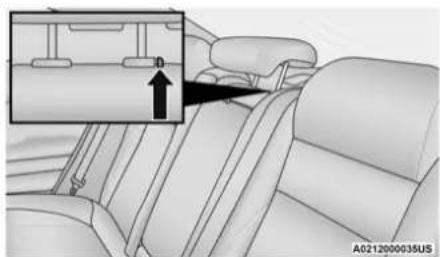
The center head restraint has two adjustable positions: up or down. When the center seat is being occupied, the head restraint should be in the raised position. When there are no occupants in the center seat, the head restraint can be lowered for maximum visibility for the driver.
To raise the head restraint, pull upward on the head restraint. To lower the head restraint, push the adjustment button located at the base of the head restraint and push downward on the head restraint.
natural_image
Interior view of a car seatbelt with a zoomed-in inset showing the seatbelt area (no text or symbols visible)Rear Head Restraint Adjustment Button
NOTE:
- The head restraint should only be removed by qualified technicians, for service purposes only. If the center rear head restraint requires removal, see an authorized dealer.
- The outboard head restraints are not adjustable.
WARNING!
ALL the head restraints MUST be reinstalled in the vehicle to properly protect the occupants. Follow the re-installation instructions above prior to operating the vehicle or occupying a seat.
Front Head Restraint Removal
To remove the head restraint, raise it up as far as it can go. Then, push the adjustment button and the release button at the base of each post while pulling the head restraint up. To reinstall the head restraint, put the head restraint posts into the holes. Then, adjust it to the appropriate height.
NOTE:
Do not reposition the head restraint 180 degrees to the incorrect position in an attempt to gain additional clearance to the back of the head.
WARNING!
- A loose head restraint thrown forward in a collision or hard stop could cause serious injury or death to occupants of the vehicle. Always securely stow removed head restraints in a location outside the occupant compartment.
(Continued)
WARNING! (Continued)
- ALL the head restraints MUST be reinstalled in the vehicle to properly protect the occupants. Follow the re-installation instructions above prior to operating the vehicle or occupying a seat.
MIRRORS
INSIDE REARVIEW MIRROR
Automatic Dimming Mirror
The rearview mirror can be adjusted up, down, left, and right. The mirror should be adjusted to center on the view through the rear window.
This mirror automatically adjusts for headlight glare from vehicles behind you.
NOTE:
The Automatic Dimming Mirror feature is disabled when the vehicle is in REVERSE to improve the driver's rear view.
The Automatic Dimming feature can be turned on or off through the Uconnect system page 144.
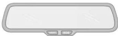
natural_image
Front view of a modern rectangular display with control buttons (no text or symbols)A0215000063US
Automatic Dimming Mirror
CAUTION!
To avoid damage to the mirror during cleaning, never spray any cleaning solution directly onto the mirror. Apply the solution onto a clean cloth and wipe the mirror clean.
ILLUMINATED VANITY MIRRORS
To access an illuminated vanity mirror, flip down one of the visors and lift the cover.
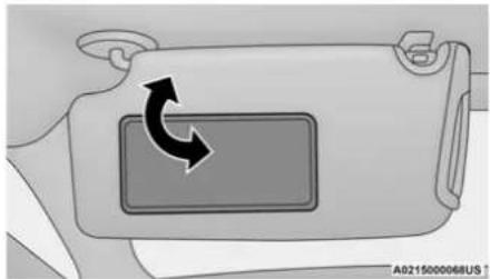
natural_image
Diagram of a device casing with a rectangular panel and directional arrow indicating rotation (no text or symbols)Illuminated Vanity Mirror
Sun Visor "Slide-On-Rod" Feature
The sun visor "Slide-On-Rod" feature allows for additional flexibility in positioning the sun visor to block out the sun.
- Fold down the sun visor.
-
Unclip the visor from the corner clip.
-
Pivot the sun visor toward the side window.
- Extend the sun visor for additional sun blockage.
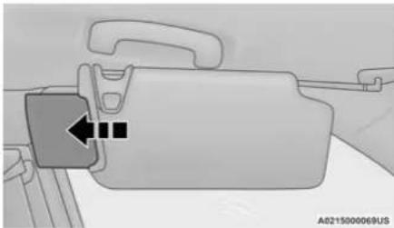
natural_image
Diagram of a vehicle seatbelt with a highlighted component and directional arrow (no text or symbols)Slide-On-Rod Feature
NOTE:
The sun visor can also be extended while the sun visor is against the windshield for additional sun blockage through the front of the vehicle.
OUTSIDE MIRRORS
The outside mirror(s) can be adjusted to the center of the adjacent lane of traffic to achieve the optimal view.
WARNING!
Vehicles and other objects seen in an outside convex mirror will look smaller and farther away than they really are. Relying too much on side convex mirrors could cause you to collide with another vehicle or other object. Use your inside mirror when judging the size or distance of a vehicle seen in a side convex mirror.
DRIVER'S OUTSIDE AUTOMATIC DIMMING MIRROR — IF EQUIPPED
The driver's outside mirror will automatically adjust for glare from vehicles behind you. This feature is controlled by the inside automatic dimming mirror and will automatically adjust for headlight glare when the inside mirror adjusts.
OUTSIDE MIRRORS WITH TURN SIGNAL AND APPROACH LIGHTING — IF EQUIPPED
Driver and passenger outside mirrors with turn signal and approach lighting contain four LEDs, which are located in the upper outer corner of each mirror.
Three of the LEDs are turn signal indicators, which flash with the corresponding turn signal lights in the front and rear of the vehicle. Turning on the Hazard Warning flashers will also activate these LEDs.
The fourth LED supplies illuminated entry lighting, which turns on in both mirrors when you use the key fob or open any door. This LED shines outward to illuminate the front and rear door handles. It also shines downward to illuminate the area in front of the doors.
The illuminated entry lighting fades to off after about 30 seconds or it will fade to off immediately once the ignition is placed into the ON/RUN position.
NOTE:
The approach lighting will not function when the gear selector is moved out of the PARK position.
POWER MIRRORS
The power mirror controls are located on the driver's door trim panel.
The power mirror controls consist of mirror select buttons and a four-way mirror control switch. To adjust a mirror, push the mirror select button for the mirror that you want to adjust.
Using the mirror control switch, push on any of the four arrows for the direction that you want the mirror to move.
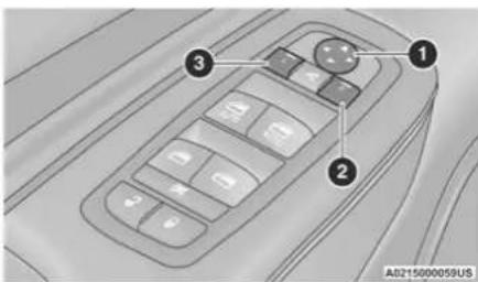
text_image
1 2 3 A0215000059USPower Mirror Controls
1 - Mirror Direction Control
2 - Right Mirror Selection
3 – Left Mirror Selection
Power mirror preselected positions can be controlled by the optional Driver Memory Settings feature → page 29.
POWER FOLDING OUTSIDE MIRRORS — IF EQUIPPED
If equipped with power folding mirrors, they can be electrically folded rearward and unfolded into the drive position.
The switch for the power folding mirrors is located between the power mirror switches L (left) and R (right). Push the switch once and the mirrors will fold in, pushing the switch a second time will return the mirrors to the normal driving position.
If the mirror is manually folded after electrically cycled, a potential extra button push is required to get the mirrors back to the drive position. If the mirror does not electrically fold, check for ice or dirt build up at the pivot area which can cause excessive drag.
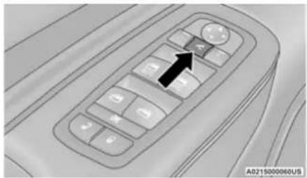
natural_image
Interior view of a car dashboard with control panel and directional arrow (no text or symbols)Power Folding Mirror Switch
Automatic Folding Mirrors
When the Automatic Folding Mirrors feature is enabled, the exterior mirrors will fold in when exiting the vehicle (with the ignition OFF and all doors closed and locked).
- If the exterior mirrors were auto-folded, they will unfold when the ignition is placed in the ON position.
- If the exterior mirrors were manually folded, they will not automatically unfold.
NOTE:
The Automatic Fold/Unfold Mirrors feature can be turned on and off using the Uconnect system page 144.
Resetting The Power Folding Outside Mirrors
You may need to reset the power folding mirrors if the following occurs:
- The mirrors are accidentally blocked while folding.
- The mirrors are accidentally manually folded/unfolded.
- The mirrors come out of the unfolded position.
- The mirrors shake and vibrate at normal driving speeds.
To reset the power folding mirrors, fold and unfold them by pushing the button (this may require multiple button pushes). This resets them to their normal position.
HEATED MIRRORS — IF EQUIPPED

These mirrors are heated to melt frost or ice. This feature will be activated whenever you turn on the rear window defroster (if equipped)
page 53.
TILT SIDE MIRRORS IN REVERSE — IF EQUIPPED
This feature provides automatic outside mirror positioning which will assist with the driver's ground visibility. The outside mirrors will move slightly downward from the present position when the vehicle is shifted into REVERSE. The outside mirrors will then return to the original position when the vehicle is shifted out of REVERSE. If the vehicle is equipped with memory settings, this feature will be linked to the programmable settings.
NOTE:
The Tilt Side Mirrors In Reverse feature can be turned on and off using the Uconnect system ➤ page 144.
UNIVERSAL GARAGE DOOR OPENER (HOMELINK®)
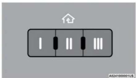
text_image
A0241000001USHomeLink® Buttons And Indicator Light
- HomeLink® replaces up to three hand-held transmitters that operate devices such as garage door openers, motorized gates, lighting, or home security systems. The HomeLink® unit is powered by your vehicles 12 Volt battery.
- The HomeLink® buttons that are located in the overhead console or sunvisor designate the three different HomeLink® channels.
42 GETTING TO KNOW YOUR VEHICLE
- To operate HomeLink®, push and release any of the programmed HomeLink® buttons. These buttons will activate the devices they are programmed to with each press of the corresponding HomeLink® button.
- The HomeLink® indicator light is located above the center button.
BEFORE YOU BEGIN PROGRAMMING HOMELINK®
For efficient programming and accurate transmission of the radio-frequency signal, it is recommended that a new battery be placed in the hand-held transmitter of the device that is being programmed to the HomeLink® system. Make sure your hand-held transmitter is programmed to activate the device you are trying to program your HomeLink® button to.
Ensure that your vehicle is parked outside of the garage before you begin programming.
It is recommended that you erase all the channels of your HomeLink® before you use it for the first time.
ERASING ALL THE HOMELINK® CHANNELS
To erase the channels, follow this procedure:
- Place the ignition switch into the ON/RUN position.
- Push and hold the two outside HomeLink® buttons (I and III) for up to 20 seconds, or until the HomeLink® indicator light flashes.
NOTE:
Erasing all channels should only be performed when programming HomeLink® for the first time. Do not erase channels when programming additional buttons.
IDENTIFYING WHETHER YOU HAVE A ROLLING CODE OR NON-ROLLING CODE DEVICE
Before programming a device to one of your HomeLink® buttons, you must determine whether the device has a rolling code or non-rolling code.
Rolling Code Devices
To determine if your device has a rolling code, a good indicator is its manufacturing date. Typically, devices manufactured after 1995 have rolling codes. A device with a rolling code will also have a "LEARN" or "TRAIN" button located where the antenna is attached to the device. The button may not be immediately visible when looking at the device. The name and color of the button may vary slightly by manufacturer.
NOTE:
The "LEARN" or "TRAIN" button is not the button you normally use to operate the device.
Non-rolling Code Devices
Most devices manufactured before 1995 will not have a rolling code. These devices will also not have a "LEARN" or "TRAIN" button.
PROGRAMMING HOMELINK® TO A GARAGE DOOR OPENER
To program any of the HomeLink® buttons to activate your garage door opener motor, follow the steps below:
NOTE:
All HomeLink® buttons are programmed using this procedure. You do not need to erase all channels when programming additional buttons.
- Place the ignition switch into the ON/RUN position.
- Place the garage door opener transmitter 1 to 3 inches (3 to 8 cm) away from the HomeLink® button you wish to program, while keeping the HomeLink® indicator light in view.
-
Push and hold the HomeLink® button you want to program while you push and hold the garage door opener transmitter button you are trying to replicate.
-
Continue to hold both buttons and observe the HomeLink® indicator light. The HomeLink® indicator light will flash slowly and then rapidly. Once this happens, release both buttons.
NOTE:
Make sure the garage door opener motor is plugged in before moving on to the rolling code/non-rolling code final steps.
Rolling Code Garage Door Opener Final Steps
NOTE:
You have 30 seconds in which to initiate rolling code final step 2, after completing rolling code final step 1.
-
At the garage door opener motor (in the garage), locate the "LEARN" or "TRAIN" button. This can usually be found where the hanging antenna wire is attached to the garage door opener motor. Firmly push and release the "LEARN" or "TRAIN" button.
-
Return to the vehicle and push the programmed HomeLink® button three times (holding the button for two seconds each time). If the garage door opener motor operates, programming is complete.
- Push the programmed HomeLink® button to confirm that the garage door opener motor operates. If the garage door opener motor does not operate, repeat the final steps for the rolling code procedure.
Non-Rolling Code Garage Door Opener Final Steps
- Push and hold the programmed HomeLink® button and observe the HomeLink® indicator light. If the HomeLink® indicator light stays on constantly, programming is complete.
- Push the programmed HomeLink® button to confirm that the garage door opener motor operates. If the garage door opener motor does not operate, repeat the steps from the beginning.
WARNING!
- Your motorized door or gate will open and close while you are programming the universal transceiver. Do not program the transceiver if people or pets are in the path of the door or gate.
- Do not run your vehicle in a closed garage or confined area while programming the transceiver. Exhaust gas from your vehicle contains Carbon Monoxide (CO) which is odorless and colorless. Carbon Monoxide is poisonous when inhaled and can cause you and others to be severely injured or killed.
PROGRAMMING HOMELINK® TO A MISCELLANEOUS DEVICE
Follow the procedure on programming HomeLink® to a garage door opener page 43. Be sure to determine if the device has a rolling code, or non-rolling code before beginning the programming process.
NOTE:
Canadian radio frequency laws require transmitter signals to time-out (or quit) after several seconds of transmission, which may not be long enough for HomeLink® to pick up the signal during programming. Similar to this Canadian law, some U.S. gate operators are designed to time-out in the same manner. The procedure may need to be performed multiple times to successfully pair the device to your HomeLink® buttons.
REPROGRAMMING A SINGLE HOMELINK® BUTTON
To reprogram a single HomeLink® button that has been previously trained, without erasing all the channels, follow the procedure below. Be sure to determine whether the new device you want to program the HomeLink® button to have a rolling code or non-rolling code.
- Place the ignition in the ON/RUN position, without starting the engine.
- Push and hold the desired HomeLink® button until the HomeLink® Indicator light begins to flash after 20 seconds. Do not release the button.
- Without releasing the button, proceed with Step 2 in "Programming HomeLink® To A Garage Door Opener" and follow all remaining steps.
CANADIAN /GATE OPERATOR PROGRAMMING
For programming transmitters in Canada/United States that require the transmitter signals to "time-out" after several seconds of transmission.
Canadian Radio Frequency (RF) laws require transmitter signals to time-out (or quit) after several seconds of transmission – which may not be long enough for HomeLink® to pick up the signal during programming. Similar to this Canadian law, some US gate operators are designed to time-out in the same manner.
It may be helpful to unplug the device during the cycling process to prevent possible overheating of the garage door or gate motor.
- Place the ignition in the ON/RUN position.
- Place the hand-held transmitter 1 to 3 inches (3 to 8 cm) away from the HomeLink® button you wish to program while keeping the HomeLink® indicator light in view.
- Continue to press and hold the HomeLink® button, while you press and release ("cycle") your hand-held transmitter every
two seconds until HomeLink® has successfully accepted the frequency signal. The indicator light will flash slowly and then rapidly when fully trained.
- Watch for the HomeLink® indicator to change flash rates. When it changes, it is programmed. It may take up to 30 seconds or longer in rare cases. The garage door may open and close while you are programming.
- Press and hold the programmed HomeLink® button and observe the indicator light.
NOTE:
- If the indicator light stays on constantly, programming is complete and the garage door/device should activate when the Home-Link® button is pressed.
- To program the two remaining HomeLink® buttons, repeat each step for each remaining button. DO NOT erase the channels.
If you unplugged the garage door opener/ device for programming, plug it back in at this time.
Reprogramming A Single HomeLink® Button (Canadian/Gate Operator)
To reprogram a channel that has been previously trained, follow these steps:
- Place the ignition in the ON/RUN position.
- Press and hold the desired HomeLink® button until the indicator light begins to flash after 20 seconds. Do not release the button.
- Without releasing the button, proceed with "Canadian/Gate Operator Programming" step 2 and follow all remaining steps page 298.
EXTERIOR LIGHTS
HEADLIGHT SWITCH
The headlight switch is located on the left side of the instrument panel. This switch controls the operation of the headlights, parking lights, instrument panel lights, interior lights and fog lights (if equipped).
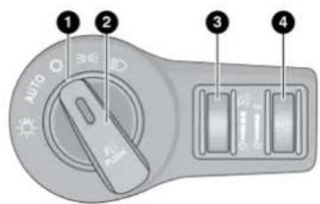
text_image
1 2 3 4 AUTO 34EA0216000134US
Headlight Switch
1 – Rotate Headlight Control
2 - Push Front Fog Light Control
3 – Instrument Panel Dimmer Control
4 - Ambient Light Dimmer Control
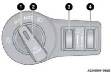
text_image
1 2 3 4 AUTO A0216000139USHeadlight Switch (Vehicles Sold In Canada Only)
1 - Rotate Headlight Control
2 — Push Front Fog Light Control
3 - Instrument Panel Dimmer Control
4 — Ambient Light Dimmer Control
NOTE:
Vehicles sold in Canada are equipped with a headlight switch without the OFF position. In order to turn the exterior lights off, the headlight switch must be rotated to AUTO position.
To turn on the headlights, rotate the headlight switch clockwise. When the headlight switch is on, the parking lights, taillights, license plate light and instrument panel lights are also turned on. To turn off the headlights, rotate the headlight switch back to the O (off) position. For vehicles sold in Canada, rotate the headlight switch clockwise from the parking light and instrument panel light position to the AUTO position for automatic headlights. Rotate to the second detent to turn on headlight, parking light, and instrument panel light operation.
MULTIFUNCTION LEVER
The multifunction lever is located on the left side of the steering column.
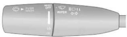
text_image
FUSH WASH WIPER OFF 10 EOT11A0216000133US
Multifunction Lever
DAYTIME RUNNING LIGHTS (DRLs)
The Daytime Running Lights will turn on when the engine is started and will remain on unless the headlights are turned to the on position, the parking brake is applied, or the ignition is placed in the OFF position.
NOTE:
- For vehicles sold in Canada, the Daytime Running Lights will automatically deactivate when the front fog lights are turned on.
- If allowed by law in the country in which the vehicle was purchased, the Daytime Running Lights can be turned on and off using the Uconnect system ↩ page 144.
- On some vehicles, the Daytime Running Lights may deactivate or reduce intensity on one side of the vehicle (when a turn signal is activated on that side), or on both sides of the vehicle (when the hazard warning lights are activated).
Push the multifunction lever toward the instrument panel to switch the headlights to high beams. Pulling the multifunction lever back will turn the low beams on.
AUTOMATIC HIGH BEAM — IF EQUIPPED
The Automatic High Beam Headlamp Control system provides increased forward lighting at night by automating high beam control through the use of a digital camera mounted on the inside rearview mirror. This camera detects
vehicle specific light and automatically switches from high beams to low beams until the approaching vehicle is out of view.
NOTE:
- The Automatic High Beam Headlamp Control can be turned on or off by selecting or deselecting "Auto High Beam" within Uconnect Settings → page 144, as well as turning the headlight switch to the AUTO position.
- Broken, muddy, or obstructed headlights and taillights of vehicles in the field of view will cause headlights to remain on longer (closer to the vehicle). Also, dirt, film, and other obstructions on the windshield or camera lens will cause the system to function improperly.
- If the windshield or Automatic High Beam Headlamp Control mirror is replaced, the mirror must be re-aimed to ensure proper performance. See a local authorized dealer.
FLASH-To-PASS
You can signal another vehicle with your headlights by lightly pulling the multifunction lever toward you. This will cause the high beam headlights to turn on, and remain on, until the lever is released.
AUTOMATIC HEADLIGHTS
This system automatically turns the headlights on or off according to ambient light levels. To turn the system on, rotate the headlight switch counterclockwise to the AUTO position. When the system is on, the headlight time delay feature is also on. This means the headlights will stay on for up to 90 seconds after placing the ignition in the OFF position. The headlight time delay can be programmed 0/30/60/90 seconds within Uconnect Settings → page 144.
To turn the automatic system off, move the headlight switch out of the AUTO position.
NOTE:
The engine must be running before the headlights will come on in the automatic mode.
PARKING LIGHTS
To turn on the parking lights and instrument panel lights, rotate the headlight switch clockwise. To turn off the parking lights, rotate the headlight switch back to the O (off) position.
NOTE:
For vehicles sold in Canada, rotate the head-light switch to the AUTO position to turn off the parking lights.
HEADLIGHTS ON WITH WIPERS
If your vehicle is equipped with Automatic Headlights, it also has this customer-programmable feature. When your headlights are in the automatic mode and the engine is running, they will automatically turn on when the wiper system is on. This feature is programmable through the Uconnect system → page 144.
NOTE:
When your headlights come on during the daytime, the instrument panel lights will automatically dim to the lower nighttime intensity.
ADAPTIVE BI-XENON HIGH INTENSITY DISCHARGE HEADLIGHTS — IF EQUIPPED
This system automatically swivels the headlight beam pattern horizontally to provide increased illumination in the direction the vehicle is being steered.
NOTE:
- Each time the Adaptive Headlight system is turned on, the headlights will initialize by performing a brief sequence of rotations.
- The Adaptive Headlight system is active only when the vehicle is moving forward.
The Adaptive Headlight system can be turned on or off using the Uconnect system page 144.
To assist when exiting the vehicle, the headlight delay feature will leave the headlights on for up to 90 seconds. This delay is initiated when the ignition is placed in the OFF position while the headlight switch is on, and then the headlight switch is cycled off within 45 seconds. Headlight delay can be cancelled by either turning the headlight switch on then off, or by placing the ignition in the ON position.
NOTE:
- This feature can be programmed through the Uconnect system ➤ page 144.
- If you turn the headlights off before the ignition, they will turn off in the normal manner.
LIGHTS-ON REMINDER
If the headlights or parking lights are on after the ignition is placed in the OFF position, a chime will sound to alert the driver when the driver's door is opened.
Fog Lights — IF EQUIPPED
The front fog light switch is built into the headlight switch.
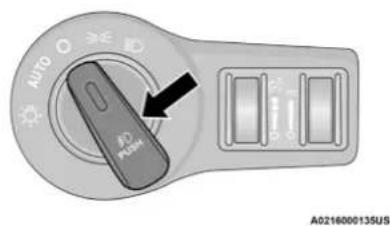
text_image
AUTO 40 PUSH A0216000135USFog Light Switch
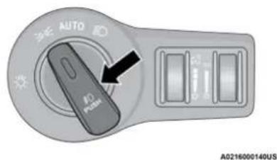
text_image
AUTO AD PLUS A0216000140USFog Light Switch (Vehicles Sold In Canada Only)
To activate the front fog lights, turn on the parking lights or the low beam headlights and push the headlight switch. To turn off the front fog lights, either push the headlight switch a second time or turn off the headlight switch.
NOTE:
The fog lights will operate with the low beam headlights or parking lights on. However, selecting the high beam headlights will turn off the fog lights.
TURN SIGNALS
Move the multifunction lever up or down to activate the turn signals. The arrows on each side of the instrument cluster flash to show proper operation.
NOTE:
- If either light remains on and does not flash, or there is a very fast flash rate, check for a defective outside light bulb.
- A "Turn Signal On" message will appear in the instrument cluster display and a continuous chime will sound if the vehicle is driven more than 1 mile (1.6 km) with either turn signal on.
LANE CHANGE ASSIST — IF EQUIPPED
Lightly push the multifunction lever up or down, without moving beyond the detent, and the turn signal will flash three times then automatically turn off.
INTERIOR LIGHTS
The interior lights come on when a door is opened.
To protect the battery, the interior lights will turn off automatically 10 minutes after the ignition is placed in the OFF position. This will occur if the interior lights were switched on manually or are on because a door is open. The Battery
Protection also includes the glove compartment light and the trunk light. To restore interior light operation after automatic battery protection is enabled (lights off), either place the ignition in the ON/RUN position, or cycle the light switch.
INTERIOR COURTESY LIGHTS
The courtesy lights can be turned on by pushing the top corner of the lens. To turn the lights off, push the lens a second time.
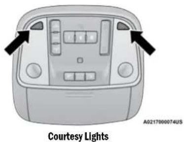
text_image
Courtesy Lights A0217000074USFront Map/Reading Lights — If Equipped The front map/reading lights are mounted in the overhead console.
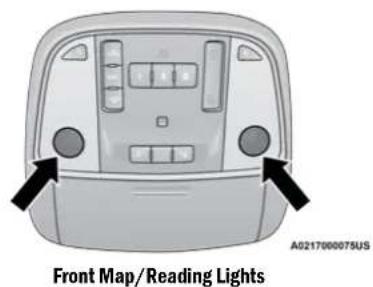
text_image
Front Map/Reading Lights A0217000075US50 GETTING TO KNOW YOUR VEHICLE
Each light can be turned on by pushing a switch on either side of the console. These buttons are backlit for night time visibility. To turn the lights off, push the switch a second time. The lights will also turn on when the unlock button on the key fob is pushed.
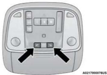
natural_image
Front view of a car dashboard with control buttons and indicator lights (no text or symbols visible)Front Map/Reading Light Switches
Ambient Light — If Equipped
The overhead console is equipped with an ambient light feature. This light casts illumination for improved visibility of the floor and center console area.
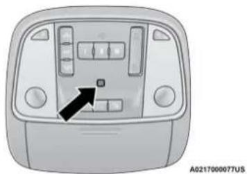
natural_image
Front view of a car dashboard with control buttons and a black arrow pointing to the dashboard (no text or symbols visible)Ambient Light
Rotate the right dimmer control upward or downward to increase or decrease the brightness of the door handle lights, map pocket lights, and ambient light located in the overhead console.
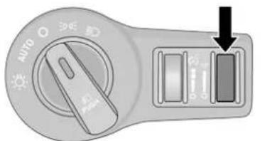
text_image
AUTO ↓A0217000108US
Door Handle/Ambient Light Dimmer
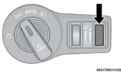
text_image
AUTO A0217000111USDoor Handle/Ambient Light Dimmer (Vehicles Sold In Canada Only)
Dimmer Controls
The brightness of the instrument panel lighting and lighted cupholders (if equipped) can be regulated by rotating the left dimmer control up (brighter) or down (dimmer). When the headlights are on you can supplement the brightness of the instrument cluster display, radio and overhead console by rotating the control to the first detent up until you hear a click. This feature is called "Parade" mode and is useful when headlights are required during the day. Rotating the dimmer control up to the second detent, the furthest position up, turns on the courtesy lights. This feature is known as "Dome On".
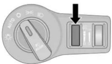
text_image
AUTO AIRA0217000107US
Instrument Panel Dimmer Control
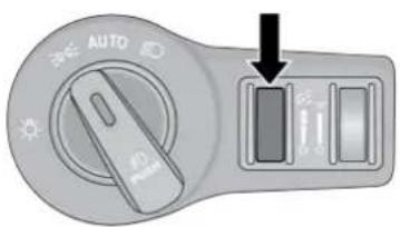
text_image
AUTO 40 AIRA0217000110US
Instrument Panel Dimmer Control (Vehicles Sold In Canada Only)
WINDSHIELD WIPERS AND WASHERS
The windshield wiper/washer controls are located on the multifunction lever on the left side of the steering column. The front wipers are operated by rotating a switch, located on the end of the lever.
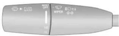
text_image
FLUSH WIPER EOT1 WIPERA0216000133US
Windshield Wiper/Washer Control
Rotate the end of the multifunction lever to the first detent, past the intermittent settings for low-speed wiper operation, or to the second detent past the intermittent settings for high-speed wiper operation.
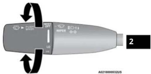
text_image
2 A0218000032USWindshield Wiper Operation
Intermittent Wipers
Rotate the end of the multifunction lever to the first detent position, and then turn the end of the lever to select the desired delay interval. There are four delay settings, which allow you to regulate the wipe interval from a minimum of one cycle every second to a maximum of approximately 36 seconds between cycles. The delay intervals will double in duration when the vehicle speed is 10 mph (16 km/h) or less.
Windshield Washers
To use the washer, push the multifunction lever inward (toward the steering wheel) and hold. If the lever is pushed while in the intermittent setting, the wipers will turn on and operate for two cycles after the end of the lever is released, and then resume the intermittent interval previously selected.
If the end of the lever is pushed while the wipers are in the off position, the wipers will operate for three wipe cycles and then turn off.
WARNING!
Sudden loss of visibility through the windshield could lead to a collision. You might not see other vehicles or other obstacles. To avoid sudden icing of the windshield during freezing weather, warm the windshield with the defroster before and during windshield washer use.
Mist
Rotate the end of the lever downward to the MIST position and release for a single wiping cycle. The wipers will continue to operate until you release the multifunction lever
NOTE:
The Mist feature does not activate the washer pump; therefore, no washer fluid will be sprayed on the windshield. The wash function must be used in order to spray the windshield with washer fluid.
For information on wiper care and replacement, see ➤ page 240.
CAUTION!
- Turn the windshield wipers off when driving through an automatic car wash. Damage to the windshield wipers may result if the wiper control is left in any position other than off.
- In cold weather, always turn off the wiper switch and allow the wipers to return to the park position before turning off the engine. If the wiper switch is left on and the wipers freeze to the windshield, damage to the wiper motor may occur when the vehicle is restarted.
(Continued)
CAUTION! (Continued)
- Always remove any buildup of snow that prevents the windshield wiper blades from returning to the off position. If the windshield wiper control is turned off and the blades cannot return to the off position, damage to the wiper motor may occur.
RAIN SENSING WIPERS — IF EQUIPPED
This feature senses rain or snowfall on the windshield and automatically activates the wipers. Rotate the end of the multifunction lever to one of four detent positions to activate this feature.
The sensitivity of the system can be adjusted with the multifunction lever. Wiper delay position one is the least sensitive, and wiper delay detent position four is the most sensitive.
Wiper delay position three should be used for normal rain conditions.
NOTE:
- The Rain Sensing feature will not operate when the wiper switch is in the low or high-speed position.
- The Rain Sensing feature may not function properly when ice, or dried salt water is present on the windshield.
- Use of Rain-X or products containing wax or silicone may reduce Rain Sensing performance.
- The Rain Sensing feature can be turned on and off using the Uconnect system page 144.
The Rain Sensing system has protection features for the wiper blades and arms, and will not operate under the following conditions:
- Low Ambient Temperature — When the ignition is first placed in the ON position, the Rain Sensing system will not operate until the wiper switch is moved, vehicle speed is greater than 3 mph (5 km/h), or the outside temperature is greater than 32°F (0°C).
- Transmission In NEUTRAL Position – When the ignition is ON, and the automatic transmission is in the NEUTRAL position, the Rain Sensing system will not operate until the wiper switch is moved, vehicle speed is greater than 3 mph (5 km/h), or the gear selector is moved out of the NEUTRAL position.
- Remote Start Mode Inhibit – On vehicles equipped with Remote Start system, Rain Sensing wipers are not operational when the vehicle is in the remote start mode.
CLIMATE CONTROLS
The Climate Control system allows you to regulate the temperature, air flow, and direction of air circulating throughout the vehicle. The controls are located on the touchscreen (if equipped) and on the instrument panel below the radio.
AUTOMATIC CLIMATE CONTROL DESCRIPTIONS AND FUNCTIONS
natural_image
Interior view of a car dashboard with air conditioners and steering wheel (no visible text or symbols)Uconnect 4C/4C NAV Automatic Climate Controls
MAX A/C Button

Press and release the MAX A/C button on the touchscreen to change the current setting to the coldest output of air. The MAX A/C indicator illuminates when MAX A/C is on. Pressing the button again will cause the MAX A/C operation to exit. In MAX A/C, the blower level and mode position can be adjusted to the desired user settings. Pressing other settings will cancel MAX A/C.
NOTE:
The MAX A/C button is only available on the touchscreen.
A/C Button

Press and release this button on the touchscreen, or push the button on the faceplate to change the current setting. The A/C indicator illuminates
when A/C is on.
Recirculation Button

Press and release this button on the touchscreen, or push the button on the faceplate, to change the system between recirculation mode and
outside air mode. The Recirculation indicator illuminates when Recirculation is on. Recirculation can be used when outside conditions such as smoke, odors, dust, or high humidity are present. Recirculation can be used in all modes. Recirculation may be unavailable (button on the touchscreen greyed out) if conditions exist that could create fogging on the inside of the windshield. The A/C can be deselected manually without disturbing the mode control selection. Continuous use of the Recirculation mode may make the inside air stuffy and window fogging may occur. Extended use of this mode is not recommended.
Auto Button

Set your desired temperature and press AUTO. AUTO will achieve and maintain your desired temperature by automatically adjusting the blower
speed and air distribution. AUTO mode is highly recommended for efficiency.
You can turn AUTO on in one of two ways:
- Press and release this button on the touchscreen.
- Push the button on the faceplate.
Toggling this function will cause the system to switch between manual mode and automatic mode ➤ page 56.
Front Defrost Button

Press and release the Front Defrost button on the touchscreen, or push and release the button on the faceplate, to change the current
airflow setting to Defrost mode. The Front Defrost indicator illuminates when Front Defrost is on. Air comes from the windshield and side window demist outlets. When the defrost button is selected, the blower level may increase. Use Defrost mode with maximum
temperature settings for best windshield and side window defrosting and defogging. When toggling the front defrost mode button, the Climate Control system will return to the previous setting.
Rear Defrost Button

Press and release the Rear Defrost button on the touchscreen, or push and release the button on the
faceplate, to turn on the rear window defroster and the heated outside mirrors (if equipped). The Rear Defrost indicator illuminates when the rear window defroster is on. The rear window defroster automatically turns off after 10 minutes.
NOTE:
Failure to follow these cautions can cause damage to the heating elements:
- Use care when washing the inside of the rear window. Do not use abrasive window cleaners on the interior surface of the window. Use a soft cloth and a mild washing solution, wiping parallel to the heating elements. Labels can be peeled off after soaking with warm water.
- Do not use scrapers, sharp instruments, or abrasive window cleaners on the interior surface of the window.
- Keep all objects a safe distance from the window.
Driver And Passenger Temperature Up And Down Buttons
These buttons provide the driver and passenger with independent temperature control.

Push the red button on the faceplate or touchscreen or press and slide the temperature bar towards the red arrow button on the touchscreen for warmer temperature settings.

Push the blue button on the faceplate or touchscreen or press and slide the temperature bar towards the blue arrow button on the touchscreen for cooler temperature settings.
SYNC Button

Press the SYNC button on the touchscreen to toggle the SYNC feature on/off. The SYNC indicator illuminates when SYNC is on. SYNC synchronizes the passenger temperature setting with the driver temperature setting. Changing the passenger's temperature setting while in SYNC will automatically exit this feature.
NOTE:
The SYNC button is only available on the touchscreen.
Blower Control

Blower Control regulates the amount of air forced through the climate control system. There are seven blower speeds available. Adjusting the blower will cause automatic mode to switch to manual operation. The speeds can be selected using either the blower control knob on the faceplate or the buttons on the touchscreen.
Faceplate
The blower speed increases as you turn the blower control knob clockwise from the lowest blower setting. The blower speed decreases as you turn the blower control knob counterclockwise.
Touchscreen
Use the small blower icon to reduce the blower setting and the large blower icon to increase the blower setting. Blower can also be selected by pressing the blower bar area between the icons.
Mode Control

Select Mode by pressing one of the Mode buttons on the touchscreen to change the airflow distribution mode. The airflow distribution mode can be adjusted so air comes from the instrument panel outlets, floor outlets, defrost outlets, and demist outlets.
Panel Mode

Air comes from the outlets in the instrument panel. Each of these outlets can be individually adjusted to direct the flow of air. The air vanes of
the center outlets and outboard outlets can be moved up and down or side to side to regulate airflow direction. There is a shut off wheel located below the air vanes to shut off or adjust the amount of airflow from these outlets.
Bi-Level Mode

Air comes from the instrument panel outlets and floor outlets. A slight amount of air is directed through the defrost and side window
demister outlets.
NOTE:
Bi-Level mode is designed under comfort conditions to provide cooler air out of the panel outlets and warmer air from the floor outlets.
Floor Mode

Air comes from the floor outlets. A slight amount of air is directed through the defrost and side window demister outlets.
Mix Mode

Air is directed through the floor, defrost, and side window demister outlets. This setting works best in cold or snowy conditions that require extra
heat to the windshield. This setting is good for maintaining comfort while reducing moisture on the windshield.
Climate Control OFF Button

Press and release the OFF button on the touchscreen, or push the OFF button on the faceplate to turn the Climate Control ON/OFF.
AUTOMATIC TEMPERATURE CONTROL (ATC)
Automatic Operation
- Push the AUTO button on the faceplate, or press and release the AUTO button on the touchscreen on the Automatic Temperature Control (ATC) Panel.
- Next, adjust the temperature you would like the system to maintain by adjusting the driver and passenger temperature control buttons. Once the desired temperature is displayed, the system will achieve and automatically maintain that comfort level.
- When the system is set up for your comfort level, it is not necessary to change the settings. You will experience the greatest efficiency by simply allowing the system to function automatically.
NOTE:
- It is not necessary to change the temperature settings for cold or hot vehicles. The system automatically adjusts the temperature, mode, and blower speed to provide comfort as quickly as possible.
- The temperature can be displayed in U.S. or Metric units within Uconnect Settings page 144.
To provide you with maximum comfort in the Automatic mode during cold start-ups, the blower fan will remain on low until the engine warms up. The blower will increase in speed and transition into Auto mode.
Manual Operation Override
This system offers a full complement of manual override features. The AUTO symbol in the front ATC display will be turned off when the system is being used in the manual mode.
CLIMATE VOICE COMMANDS
Adjust vehicle temperatures hands-free and keep everyone comfortable while you keep moving ahead.
Push the VR button. After the beep, say one of the following commands:
- "Set the driver temperature to 70 degrees"
- "Set the passenger temperature to 70 degrees"
TIP:
Voice Command for Climate may only be used to adjust the interior temperature of your vehicle. Voice Command will not work to adjust the heated seats or steering wheel if equipped.
OPERATING TIPS
NOTE:
Refer to the chart at the end of this section for suggested control settings for various weather conditions.
Summer Operation
The engine cooling system must be protected with a high-quality antifreeze coolant to provide proper corrosion protection and to protect against engine overheating. OAT coolant (conforming to MS.90032) is recommended.
Winter Operation
To ensure the best possible heater and defroster performance, make sure the engine cooling system is functioning properly and the proper amount, type, and concentration of coolant is used. Use of the Air Recirculation mode during Winter months is not recommended, because it may cause window fogging.
Vacation/Storage
For information on maintaining the Climate Control system when the vehicle is being stored for an extended period of time, see
page 283.
Window Fogging
Vehicle windows tend to fog on the inside in mild, rainy, and/or humid weather. To clear the windows, select Defrost or Mix mode and increase the front blower speed. Do not use the Recirculation mode without A/C for long periods, as fogging may occur.
Outside Air Intake
Make sure the air intake, located directly in front of the windshield, is free of obstructions, such as leaves. Leaves collected in the air intake may reduce airflow, and if they enter the air distribution box, they could plug the water drains. In Winter months, make sure the air intake is clear of ice, slush, and snow.
Cabin Air Filter
The Climate Control system filters out dust and pollen from the air. Contact an authorized dealer to service your cabin air filter, and to have it replaced when needed.
Operating Tips Chart
| WEATHER | CONTROL SETTINGS |
| Hot Weather And Vehicle Interior Is Very Hot | Set the mode control to Panel Mode),A/C(MAX A/C) on, and blower on high. Roll down the windows for a minute to flush out the hot air. Adjust the controls as needed to achieve comfort. |
| Warm Weather | Turn (A/C) on and set the mode control to the Panel Mode) position. |
| WEATHER | CONTROL SETTINGS |
| Cool Sunny | Operate in Bi-Level Mode position. |
| Cool & Humid Conditions | Set the mode control to Mix Mode and turn on A/C to keep windows clear. |
| Cold Weather | Set the mode control to the Floor Mode position. If windshield fogging starts to occur, move the control to the Mix Mode position. |
INTERIOR STORAGE AND EQUIPMENT
STORAGE
Glove Compartment
The glove compartment is located on the passenger side of the instrument panel.
To open the glove compartment, pull the release handle.
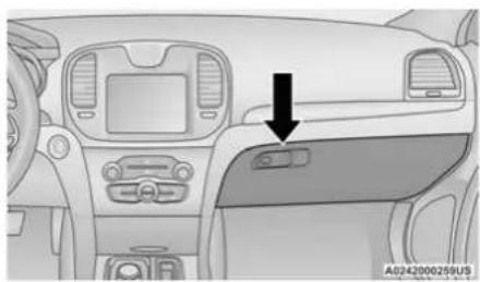
natural_image
Interior view of a car dashboard with control panels and a black arrow pointing to the side panel (no text or symbols visible)Glove Compartment
WARNING!
Do not operate this vehicle with a glove compartment in the open position. Driving with the glove compartment open may result in injury in a collision.
Cubby Bin
There is a cubby bin located forward of the gear selector. The cubby bin is covered with a push-push actuated door. Push inward on the door to open it; push the door a second time to close it.
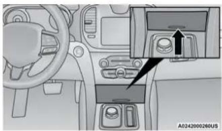
natural_image
Interior view of a car dashboard with steering wheel, dashboard, and control panel (no visible text or symbols)Cubby BIn
Door Storage
The door panels contain storage areas.
Console Features
Two separate storage compartments are located underneath the center console armrest.
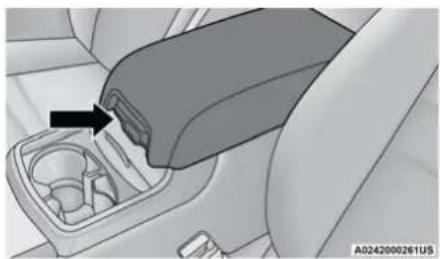
natural_image
Interior view of a car showing a car's rear gear shift lever and intake manifold (no text or symbols visible)Center Console
Inside the center console armrest, there is a removable upper storage tray that can be slid forward/rearward on rails for access to the lower storage area. This tray has an integrated coin holder, along with additional area for small items and handheld devices. Below the upper tray, the lower storage compartment is made for larger items. In addition, the 12 Volt power outlet, USB, and AUX jack are located here.
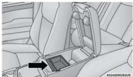
natural_image
Interior view of a car dashboard and seat area showing the left side of the dashboard and internal compartments (no text or symbols visible)Upper Storage Tray
WARNING!
Do not operate this vehicle with a console compartment lid in the open position. Driving with the console compartment lid open may result in injury in a collision.
Rear Seat Armrest Storage — If Equipped
For rear passengers, there is a storage bin located in the armrest. Lift upward on the latch to open the storage compartment.
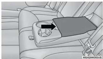
natural_image
Interior view of a car seatbelt with a black arrow pointing to the side panel (no text or symbols visible)Rear Armrest Storage
Sunglasses Bin Door
At the front of the console, a compartment is provided for the storage of a pair of sunglasses. The storage compartment access is a push-push design. Push the chrome pad on the door to open. Push the chrome pad on the door to close.
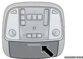
natural_image
Front view of a car dashboard with control panel and buttons (no visible text or symbols)Sunglasses Bin Door
USB/AUX CONTROL
This feature allows an external USB device to be plugged into the USB port.
Plugging in a smartphone device to a USB port may activate Android Auto™ or Apple CarPlay® features, if equipped. For further information, refer to "Android Auto™" or "Apple CarPlay®" in the Owner's Manual Supplement.
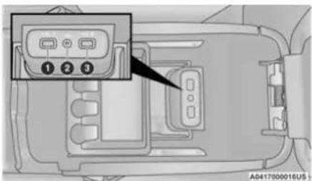
text_image
1 2 3 AD417000016U5AUX/USB Ports
1 - USB 1 Port
2 - AUX Jack
3 - USB 2 Port
Located on the rear of the front center console are dual USB "Charge Only" ports. The USB "Charge Only" ports will recharge battery operated USB devices when connected.
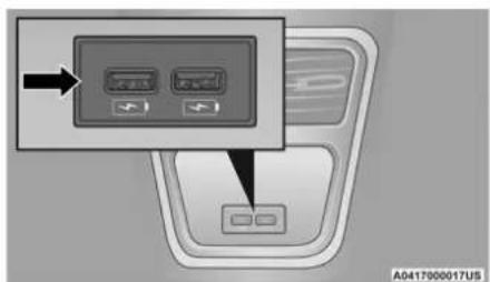
text_image
A0417000017USRear USB Charging Ports
LIGHTED CUPHOLDERS — IF EQUIPPED
On some vehicles, the front cupholders are equipped with a light ring that illuminates the cupholders for the front passengers.
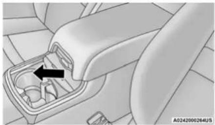
natural_image
Interior view of a car gear shift lever with a black arrow indicating the component (no text or symbols present)Light Ring In Front Cupholder
The rear cupholders may also be equipped with a light ring that illuminates the cupholders for the rear passengers. The light ring is controlled by the Dimmer Control page 50.
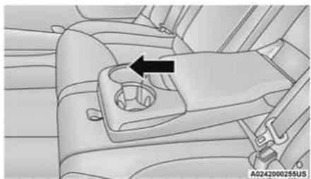
natural_image
Interior view of a car seatbelt with a black arrow pointing to the side panel (no text or symbols visible)Light Ring In Rear Cupholder
HEATED AND COOLED CUPHOLDERS — IF EQUIPPED
Your vehicle may be equipped with heated and cooled cupholders. The cupholders are designed to help keep warm beverages warm and cool beverages cool.
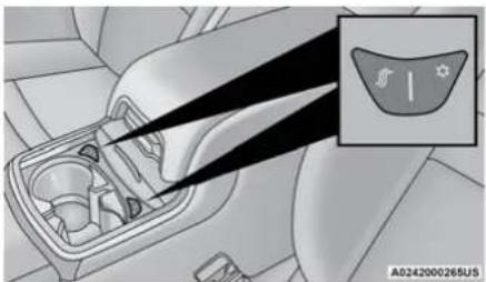
natural_image
Interior view of a car showing the dashboard and intake manifold, with an inset highlighting a gear or component (no text or symbols present)Heated And Cooled Cupholder Switches
Push the "Cold" symbol once to turn on the cupholder. Push the symbol a second time to turn the cupholder off. Push the "Hot" symbol once to activate the cupholder. Push the symbol a second time to turn off the cupholder.
WARNING!
When using the cupholder in the "Hot" position, avoid contact with the heated portion of the cupholder in order to reduce the possibility of burns. Persons who are unable to feel pain to the skin because of advanced age, chronic illness, diabetes, spinal cord injuries, medication, alcohol use, exhaustion or other physical condition must exercise particular care in order to prevent serious burn injury. Keep the cupholder free of debris or stray objects when operated in the "Hot" position.
POWER SUNSHADE — IF EQUIPPED
Your vehicle may be equipped with a power sunshade that will reduce the amount of sunlight that will shine through the rear windshield.
The power sunshade can be operated using the Uconnect system ➤ page 144.
Press the "Controls" button and then press the "Rear Sunshade" button to raise the power sunscreen. Press the "Rear Sunshade" button a second time to lower the sunshade.
If the sunshade is in the raised position and the vehicle is placed in REVERSE, the sunshade will automatically fully lower. When the transmission is shifted out of REVERSE the sunshade will automatically return to the fully raised position after a brief delay.
The power sunshade can also be operated by passengers in the rear seats. The power sunshade switch is located on the back of the center console between the heated seat switches. Push the switch once to raise the sunshade. Push the switch a second time to lower the sunshade.
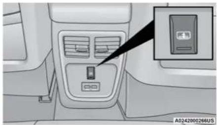
natural_image
Interior view of a car air conditioner unit with a close-up of the front panel showing a device (no text or symbols visible)Power Sunshade Switch Behind Center Console
NOTE:
The rear sunshade control switch can be locked out along with the rear passenger window controls from the driver switch window lockout switch.
POWER OUTLETS
Your vehicle is equipped with one 12 Volt (13 Amp) power outlet on the instrument panel and one 12 Volt (13 Amp) power outlet in the center console that can be used to power cellular phones, small electronics and other low powered electrical accessories. The power outlets are labeled with either a "key" or a "battery" symbol to indicate how the outlet is powered. Power outlets labeled with a "key" are powered when the ignition switch is in the ACC or ON/RUN position, while the outlets labeled with a "battery" are connected directly to the battery and powered at all times.
NOTE:
All accessories connected to the "battery" powered outlets should be removed or turned off when the vehicle is not in use to protect the battery against discharge.
The front power outlet is located inside the storage area on the center stack of the instrument panel.
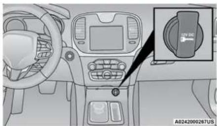
natural_image
Interior view of a car dashboard with steering wheel and infotainment panel (no text or symbols visible)Front Power Outlet
WARNING!
Do not place ashes inside the cubby bin located on the center console on vehicles not equipped with the ash receiver tray. A fire leading to bodily injury could result.
In addition to the front power outlet, there is also a power outlet located in the storage area of the center console.
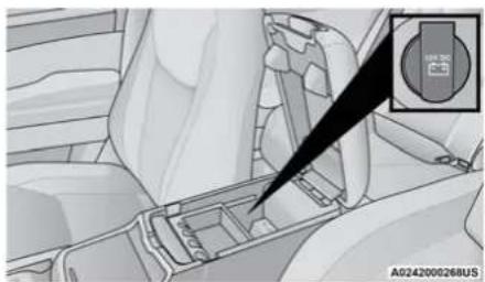
natural_image
Interior view of a car gear shift lever with a black arrow pointing to the component (no text or symbols visible)Center Console Power Outlet
NOTE:
If the Media Hub is in use, do not exceed the maximum power of 100 Watts (8 Amps) for the center console power outlet. When the Media Hub is not in use, the outlet can deliver up to 120 Watts (10 Amps). If the power rating is exceeded, the fuse protecting the system will need to be replaced.
The instrument panel power outlet and dual rear console USB ports can be changed to "battery" powered at all times by moving the #12 20 Amp fuse from "IGN" to "B+". These fuses are located in the fuse box in the trunk, below the load floor.
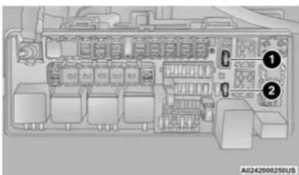
text_image
① ② A0242000250USPower Outlet Fuse Locations
1 - #12 Fuse 20 Amp Yellow Instrument Panel Power Outlet/Dual USB Charge Only Ports
2 — #38 Fuse 20 Amp Yellow Center Console Power Outlet/Media Hub
WARNING!
To avoid serious injury or death:
- Only devices designed for use in this type of outlet should be inserted into any 12 Volt outlet.
- Do not touch with wet hands.
- Close the lid when not in use and while driving the vehicle.
- If this outlet is mishandled, it may cause an electric shock and failure.
CAUTION!
- Many accessories that can be plugged in draw power from the vehicle's battery even when not in use (i.e., cellular phones, etc.). Eventually, if plugged in long enough, the vehicle's battery will discharge sufficiently to degrade battery life and/or prevent the engine from starting.
(Continued)
CAUTION! (Continued)
- Accessories that draw higher power (i.e., coolers, vacuum cleaners, lights, etc.) will degrade the battery even more quickly. Only use these intermittently and with greater caution.
- After the use of high power draw accessories or long periods of the vehicle not being started (with accessories still plugged in), the vehicle must be driven a sufficient length of time to allow the alternator to recharge the vehicle's battery.
- Power outlets are designed for accessory plugs only. Do not hang any type of accessory or accessory bracket from the plug. Improper use of the power outlet can cause damage.
WINDOWS
The window controls on the driver's door control all the door windows.
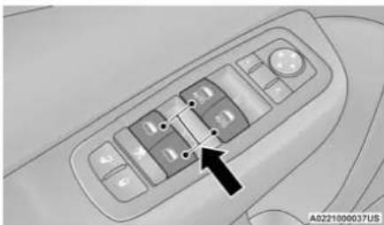
natural_image
Interior view of a car dashboard with control panel and buttons (no visible text or symbols)Power Window Switches
The passenger door windows can also be operated by using the single window controls on the passenger door trim panel. The window controls will operate only when the ignition is in the ACC or ON/RUN position.
NOTE:
The power window switches will remain active for up to 10 minutes after the ignition is placed in the OFF position. Opening either front door will cancel this feature. The timing is programmable within Uconnect Settings → page 144.
WARNING!
Never leave children unattended in a vehicle, and do not let children play with power windows. Do not leave the key fob in or near the vehicle, or in a location accessible to children, and do not leave the ignition of a vehicle equipped with Keyless Enter-N-Go in the ACC or ON/RUN mode. Occupants, particularly unattended children, can become entrapped by the windows while operating the power window switches. Such entrapment may result in serious injury or death.
AUTOMATIC WINDOW FEATURES
Auto-Down Feature
The driver and front passenger door power window switches have an Auto-Down feature. Push the window switch down to the second detent, release, and the window will go down automatically.
To stop the window from going all the way down during the Auto-Down operation, pull up or push down on the switch briefly.
Auto-Up Feature With Anti-Pinch Protection
Pull the window switch up to the second detent and the window will go up automatically.
To stop the window from going all the way up during the Auto-Up operation, push down on the switch briefly.
To close the window part way, lift the window switch briefly and release it when you want the window to stop.
If the window runs into any obstacle during auto-closure, it will reverse direction and then go back down. Remove the obstacle and use the window switch again to close the window.
NOTE:
Any impact due to rough road conditions may trigger the auto-reverse function unexpectedly during auto-closure. If this happens, pull the switch lightly and hold to close the window manually.
WARNING!
There is no anti-pinch protection when the window is almost closed. To avoid personal injury be sure to clear your arms, hands, fingers and all objects from the window path before closing.
RESET AUTO-UP
Should the Auto-Up feature stop working, the window may need to be reset. To reset Auto-Up:
- Make sure the door is fully closed.
- Pull the window switch up to close the window completely and continue to hold the switch up for an additional two seconds after the window is closed.
- Push the window switch down firmly to the second detent to open the window completely and continue to hold the switch down for an additional two seconds after the window is fully open.
WINDOW LOCKOUT SWITCH
The window lockout switch on the driver's door trim panel allows you to disable the window controls on the rear passenger doors. To disable the window controls, push and release the window lockout button (the indicator light on the button will turn on). To enable the window controls, push and release the window lockout button again (the indicator light on the button will turn off).
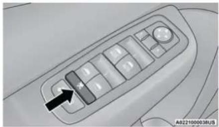
natural_image
Close-up of a car's dashboard control panel with a black arrow pointing to the left button (no text or symbols visible)Window Lockout Switch
WIND BUFFETING
Wind buffeting can be described as the perception of pressure on the ears or a helicopter-type sound in the ears. Your vehicle may exhibit wind buffeting with the windows down, or the sunroof (if equipped) in certain open or partially open positions. This is a normal occurrence and can be minimized. If the buffeting occurs with the rear windows open, open the front and rear windows together to minimize the buffeting. If the buffeting occurs with the sunroof open, adjust the sunroof opening to minimize the buffeting or open any window.
PANORAMIC SUNROOF — IF EQUIPPED
The Panoramic sunroof switch is located to the left between the sun visors on the overhead console.
The power shade switch is located to the right between the sun visors on the overhead console.
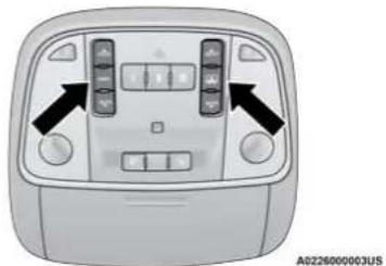
natural_image
Front view of a car dashboard with two vertical buttons and directional arrows indicating navigation (no text or symbols)Panoramic Sunroof And Power Shade Switches
WARNING!
- Never leave children unattended in a vehicle, or with access to an unlocked vehicle. Never leave the key fob in or near the vehicle, or in a location accessible to children. Do not leave the ignition of a vehicle equipped with Keyless Enter-N-Go in the ACC or ON/RUN mode. Occupants, particularly unattended children, can become entrapped by the power sunroof while operating the power sunroof switch. Such entrapment may result in serious injury or death.
- In a collision, there is a greater risk of being thrown from a vehicle with an open sunroof. You could also be seriously injured or killed. Always fasten your seat belt properly and make sure all passengers are also properly secured.
- Do not allow small children to operate the sunroof. Never allow your fingers, other body parts, or any object, to project through the sunroof opening. Injury may result.
OPENING AND CLOSING THE SUNROOF
Express Open/Close
Push the switch rearward and release it within one-half second and the sunroof will open automatically from any position. The sunroof will open fully and stop automatically.
Push the switch forward and release it within one-half second and the sunroof will close automatically from any position. The sunroof will close fully and stop automatically.
During Express Open or Express Close operation, any other movement of the sunroof switch will stop the sunroof.
Manual Open/Close
To open the sunroof, push and hold the switch rearward to full open.
To close the sunroof, push and hold the switch in the forward position.
Any release of the switch during open or close operation will stop the sunroof movement. The sunroof and sunshade will remain in a partially opened position until the switch is operated and held again.
PINCH PROTECT FEATURE
This feature will detect an obstruction in the closing of the sunroof during the Express Close operation. If an obstruction in the path of the sunroof is detected, the sunroof will automatically retract. Remove the obstruction if this occurs.
NOTE:
If three consecutive sunroof close attempts result in Pinch Protect reversals, Pinch Protect will disable and the sunroof must be closed in Manual Mode.
VENTING SUNROOF
Push and release the "Vent" button within one-half second and the sunroof will open to the vent position. This is called "Express Vent", and it will occur regardless of sunroof position. During Express Vent operation, any movement of the switch will stop the sunroof.
NOTE:
If the sunshade is in the closed position when the vent switch is pushed, the sunshade will automatically cycle to the halfway open position prior to the sunroof opening to the Vent position.
OPENING AND CLOSING THE POWER SHADE
Express Open/Close
Push the shade switch rearward and release it within one-half second and the shade will automatically open to the halfway position and stop automatically. Push the switch again to fully open the shade.
Push the switch forward and release it within one-half second and the shade will close automatically from any position.
During Express Open or Express Close operation, any other movement of the shade switch will stop the shade.
Manual Open/Close
To open the shade, push and hold the switch rearward. The shade will open and stop automatically at the half-open position. Push and hold the switch again and the shade will fully open.
To close the shade, push and hold the switch in the forward position.
Any release of the switch will stop the movement and the shade will remain in a partially closed condition until the switch is pushed again.
SUNROOF MAINTENANCE
Use only a non-abrasive cleaner and a soft cloth to clean the glass panel. Periodically check for and clear out any debris that may have collected in the tracks.
The power sunroof switch can remain active in Accessory Delay for up to approximately 10 minutes after the vehicle's ignition is placed to the OFF position. Opening either front door will cancel this feature.
This feature is programmable using the Uconnect system ➤ page 144.
HOOD
OPENING THE HOOD
To open the hood, two latches must be released.
- Pull the release lever located underneath the driver's side of the instrument panel.
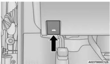
text_image
A0237000031USHood Release Lever
- Reach under the hood, move the safety latch to the left, and lift the hood.
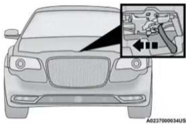
natural_image
Front view of a car with a close-up inset showing internal components (no text or symbols)Hood Safety Latch
CLOSING THE HOOD
Hoods equipped with gas props are closed from the point where the props no longer hold the hood open.
WARNING!
Be sure the hood is fully latched before driving your vehicle. If the hood is not fully latched, it could open when the vehicle is in motion and block your vision. Failure to follow this warning could result in serious injury or death.
CAUTION!
To prevent possible damage, do not slam the hood to close it. Lower hood to approximately 12 inches (30 cm) and drop the hood to close. Make sure hood is fully closed for both latches. Never drive vehicle unless hood is fully closed, with both latches engaged.
TRUNK
OPENING THE TRUNK
The trunk may be opened in several ways:
- Power trunk release button on the instrument panel
- Trunk button on the key fob
- Trunk Passive Entry button ➔ page 22
With the ignition in the ON/RUN position, the trunk open symbol will display in the instrument cluster indicating that the trunk is open. The odometer display will reappear once the trunk is closed.
70 GETTING TO KNOW YOUR VEHICLE
With the ignition in the OFF position, the trunk open symbol will display until the trunk is closed.
Power Trunk Release Button

The trunk can be opened from inside the vehicle using the power trunk release button located on the instrument panel to the left of the
steering wheel.
NOTE:
The transmission must be in PARK before the button will operate.
Key Fob Trunk Release Button

Push the power trunk button on the key fob twice within five seconds to release the trunk.
Passive Entry Button
Push the trunk passive entry button which is located on the right side of the trunk lid. With a valid Passive Entry key fob within 5 ft (1.5 m) of the trunk, push the passive entry button to open the trunk.
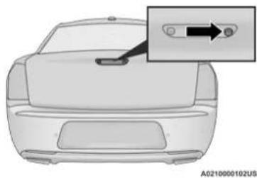
natural_image
Top-down view of a car front panel with a close-up inset showing a switch (no text or symbols)Trunk Passive Entry Button
CLOSING THE TRUNK
With one or more hands placed on the outside trunk surface push the trunk lid down until you hear the trunk lock latch into place.
NOTE:
Before closing the trunk lid make sure your key fob isn't inside the trunk area. The trunk will latch then automatically unlock if the key fob is sensed, not allowing the key fob to be locked in the trunk area.
TRUNK SAFETY
Trunk Emergency Release
As a security measure, a trunk internal emergency release lever is built into the trunk latching mechanism. In the event of an individual being locked inside the trunk, the trunk can be opened by actuating the glow-in-the-dark handle attached to the trunk latching mechanism.
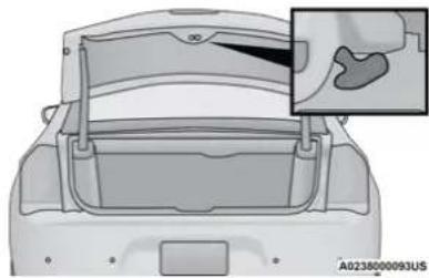
natural_image
Top-down view of a car backrest with a magnified inset showing a highlighted component (no text or symbols)Trunk Emergency Release
WARNING!
Do not allow children to have access to the trunk, either by climbing into the trunk from outside, or through the inside of the vehicle. Always close the trunk lid when your vehicle is unattended. Once in the trunk, young children may not be able to escape, even if they entered through the rear seat. If trapped in the trunk, children can die from suffocation or heat stroke.
CARGO AREA FEATURES
60/40 Split-Folding Rear Seat — If Equipped
The 60/40 split-folding rear seat provides cargo-carrying versatility. The seatbacks fold down easily by pulling nylon tabs between the seatbacks and the bolsters. When the seats are folded down, they provide a continuous, nearly-flat extension of the load floor.
When the seatback is folded to the upright position, make sure it is latched by strongly pulling on the top of the seatback above the seat strap.
WARNING!
- Be certain that the seatback is securely locked into position. If the seatback is not securely locked into position, the seat will not provide the proper stability for child seats and/or passengers. An improperly latched seat could cause serious injury.
- The cargo area in the rear of the vehicle (with the rear seatbacks in the locked-up or folded down position) should not be used as a play area by children at any time. They could be seriously injured in a collision. Children should be seated and using the proper restraint system.
- To help protect against personal injury, passengers should not be seated in the rear cargo area. The rear cargo space is intended for load carrying purposes only, not for passengers, who should sit in seats and use seat belts.
(Continued)
WARNING! (Continued)
The weight and position of cargo and passengers can change the vehicle center of gravity and vehicle handling. To avoid loss of control resulting in personal injury, follow these guidelines for loading your vehicle:
- Always place cargo evenly on the cargo floor. Put heavier objects as low and as far forward as possible.
- Place as much cargo as possible in front of the rear axle. Too much weight or improperly placed weight over or behind the rear axle can cause the rear of the vehicle to sway.
- Do not pile luggage or cargo higher than the top of the seatback. This could impair visibility or become a dangerous projectile in a sudden stop or collision.
72 GETTING TO KNOW YOUR VEHICLE
Trunk Mat — If Equipped
A trunk mat covers the bottom of the cargo area. The trunk mat is used to protect the interior of the trunk from mud, snow, and debris.
Grocery Bag Hooks
The rear cargo area is equipped with grocery bag hooks, located on either side of the rear cargo area.
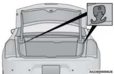
natural_image
Top-down view of a car back panel with a close-up inset showing a hook detail (no text or symbols)Grocery Bag Hooks
CAUTION!
Do not exceed the maximum weight limit 50 lbs (22 kg) of the grocery bag hook. Damage may occur to hook and mounting surface.
Cargo Net — If Equipped
The rear cargo area may be equipped with a cargo net to keep items secure while driving.
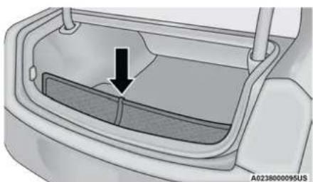
natural_image
Diagram of a car back panel with a black arrow pointing to the interior (no text or symbols)Rear Cargo Net
Attachment
To attach the cargo net, the clips must be hooked through the loops on both sides of the cargo area.
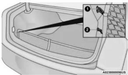
natural_image
Diagram of a car trunk with a cable inserted into the opening, showing part number 2 and a magnified inset (no text or symbols)Cargo Net Attachments
1 - Top Attachment
2 - Bottom Attachment
LOAD LEVELING SYSTEM — IF EQUIPPED
The automatic load leveling system will provide a level-riding vehicle under most passenger and cargo loading conditions.
A hydraulic pump contained within the shock absorbers raises the rear of the vehicle to the correct height. It takes approximately 1 mile (1.6 km) of driving for the leveling to complete depending on road surface conditions.
If the leveled vehicle is not moved for approximately 15 hours, the leveling system will bleed itself down. The vehicle must be driven to reset the system.
GETTING TO KNOW YOUR INSTRUMENT PANEL
INSTRUMENT CLUSTER
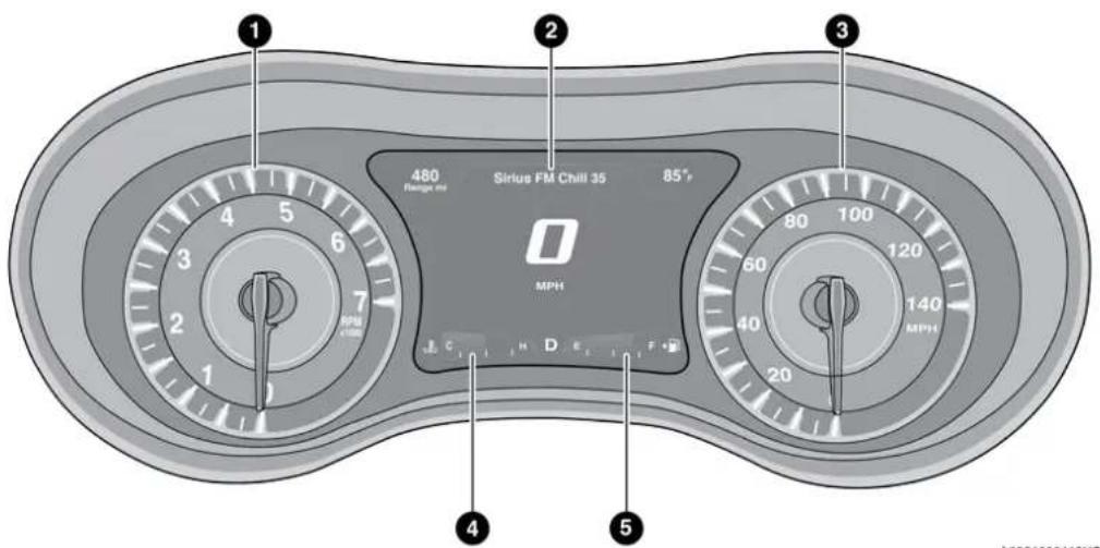
text_image
1 2 3 480 Risigus m Sirius FM Chill 35 85° 0 MPH C H D E F 20 60 40 80 100 120 140 MPH 4 5 6 7 MPH A9201000118USInstrument Cluster For 3.6L Engine
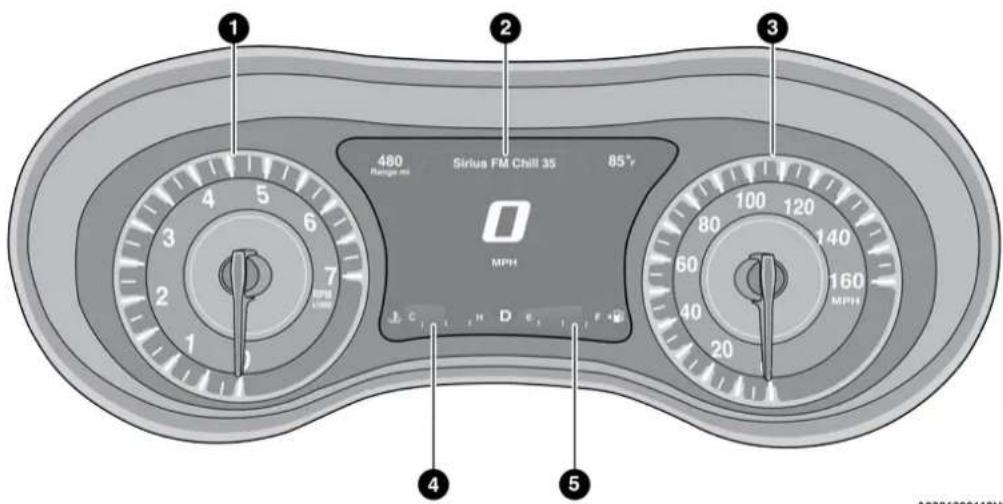
text_image
1 2 3 480 Range ms Sirius FM Chill 35 85° 0 MPH J C 1 H D E 1 F 2 G 160 MPH 80 60 40 20 4 5 A0701600119USInstrument Cluster For 5.7L Engine
INSTRUMENT CLUSTER DESCRIPTIONS
1. Tachometer
- Indicates the engine speed in revolutions per minute (RPM x 1000).
2. Instrument Cluster Display
- When the appropriate conditions exist, this display shows the instrument cluster display messages ➤ page 75.
3. Speedometer
- Indicates vehicle speed.
4. Temperature Gauge
- The temperature gauge shows engine coolant temperature. Any reading within the normal range indicates that the engine cooling system is operating satisfactorily.
- The gauge pointer will likely indicate a higher temperature when driving in hot weather, up mountain grades, or when towing a trailer. It should not be allowed to exceed the upper limits of the normal operating range.
WARNING!
A hot engine cooling system is dangerous. You or others could be badly burned by steam or boiling coolant. It is recommended to call an authorized dealer for service if your vehicle overheats.
CAUTION!
Driving with a hot engine cooling system could damage your vehicle. If the temperature gauge reads "H," pull over and stop the vehicle. Idle the vehicle with the air conditioner turned off until the pointer drops back into the normal range. If the pointer remains on the "H," turn the engine off immediately and call an authorized dealer for service.
5. Fuel Gauge
- The pointer shows the level of fuel in the fuel tank when the Keyless Push Button Ignition is in the ON/RUN position.

- The fuel pump symbol points to the side of the vehicle where the fuel door is located.
NOTE:
The warning / indicator Lights will briefly illuminate for a bulb check when the ignition is first cycled.
INSTRUMENT CLUSTER DISPLAY
Your vehicle is equipped with an instrument cluster display, which offers useful information to the driver. With the ignition in the OFF mode, opening/closing of a door will activate the display for viewing, and display the total miles, or kilometers, in the odometer. Your instrument cluster display is designed to display important information about your vehicle's systems and features. Using a driver interactive display located on the instrument panel, your instrument cluster display can show you how systems are working and give you warnings when they are not. The steering wheel mounted controls allow you to scroll through the main menus and submenus. You can access the specific information you want and make selections and adjustments.
76 GETTING TO KNOW YOUR INSTRUMENT PANEL
LOCATION AND CONTROLS
The instrument cluster display features an interactive display which is located in the instrument cluster.
This system conveniently allows the driver to select a variety of useful information by pushing the arrow buttons located on the left side of the steering wheel. The instrument cluster display menu items consist of the following:
- Speedometer
- Vehicle Info
- Driver Assist — If Equipped
- Fuel Economy
- Trip
- Audio
- Messages
- Screen Setup
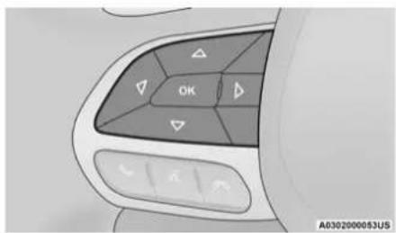
text_image
OK A0302000053USInstrument Cluster Display Controls
Up And Down Arrow Buttons:
Using the up or down arrow buttons allows you to cycle through the Main Menu Items.
Changes the Main Screen area and Menu Title area.
Left And Right Arrow Buttons:
Using the left ◀ or right ▷ arrow button allows you to cycle through the submenu items of the Main menu item.
NOTE:
- Holding the up/down or left/right arrow button will loop the user through the currently selected menu or options presented on the screen.
- Upon returning to a main menu, the last submenu screen viewed within that main menu will be displayed.
OK Button:
For Digital Speedometer:
- Pushing the OK button changes units (mph or km/h).
For Screen Setup: - OK button allows user to enter menu and submenus.
-
Within each submenu layer, the up △ and down arrow buttons will allow the user to select the item of interest.
-
Pushing the OK button makes the selection. A confirmation screen will appear, returning the user to the first page of the submenu.
- Pushing the left ◀ arrow button will exit each submenu layer and return to the main menu.
For the Trip and Fuel Economy menus:
- Information is reset by pushing and holding the OK button.
ENGINE OIL LIFE RESET
Oil Change Required
Your vehicle is equipped with an engine oil change indicator system. The “Oil Change Required” message will display in the instrument cluster display for five seconds after a single chime has sounded, to indicate the next scheduled oil change interval. The engine oil change indicator system is duty cycle based, which means the engine oil change interval may fluctuate, dependent upon your personal driving style.
Unless reset, this message will continue to display each time you place the ignition in the ON/RUN position. To turn off the message temporarily, push and release the OK or arrow buttons. To reset the oil change indicator system (after performing the scheduled maintenance), refer to the following procedure.
Vehicles Equipped With Keyless Enter-N-Go — Ignition
Use the steering wheel instrument cluster display controls for the following procedure(s):
- Without pressing the brake pedal, push the ENGINE START/STOP button and place the ignition in the ON/RUN position (do not start the engine).
- Push and release the down arrow button to scroll downward through the main menu to "Vehicle Info."
- Push and release the right arrow button to access the "Oil Life" screen.
-
Push and hold the OK button to reset oil life. If conditions are met, the gauge and numeric display will update to show 100%. If conditions are not met a pop-up message of "To reset oil life engine must be off with ignition in run" will be displayed (for five seconds), and the user will remain at the Oil Life screen.
-
Push and release the up or down arrow button to exit the submenu screen.
NOTE:
If the indicator message illuminates when you start the vehicle, the oil change indicator system did not reset. If necessary, repeat this procedure.
Secondary Method Of Resetting Engine Oil Life
- Without pressing the brake pedal, push the ENGINE START/STOP button and place the ignition to the ON/RUN position (do not start the engine).
- Fully press the accelerator pedal, slowly, three times within ten seconds.
- Without pushing the brake pedal, push the ENGINE START/STOP button once to return the ignition to the OFF/LOCK position.
NOTE:
If the indicator message illuminates when you start the vehicle, the oil change indicator system did not reset. If necessary, repeat this procedure.
78 GETTING TO KNOW YOUR INSTRUMENT PANEL
INSTRUMENT CLUSTER DISPLAY SELECTABLE MENU ITEMS
Push and release the up or down arrow button until the desired Selectable Menu item is displayed in the instrument cluster display.
Follow the Menu or submenu prompts as desired.
Speedometer
Push and release the OK button to toggle between mph and km/h.
Vehicle Info
The Vehicle Info consists of the following submenu (pushing the left or right arrow button will allow you to scroll through the submenu):
- Tire Pressure Monitor
- Coolant Temperature
• Transmission Temperature - Oil Temperature
-
Oil Pressure
-
Oil Life
- Battery Voltage
- AWD Status — If Equipped
Driver Assist — If Equipped
The Driver Assist menu provides the status and visuals about the Adaptive Cruise Control and LaneSense features. When they are both off the screen, the display will read "Adaptive Cruise Control (ACC) and LaneSense Off."
Adaptive Cruise Control (ACC) Feature — If Equipped → page 109
The instrument cluster display displays the current ACC system settings. The information displayed depends on ACC system status.
Push the ACC ON/OFF button (located on the steering wheel) until one of the following displays in the instrument cluster display:
Adaptive Cruise Control Off
When ACC is deactivated, the display will read "Adaptive Cruise Control Off."
Adaptive Cruise Control Ready
When ACC is activated but the vehicle speed setting has not been selected, the display will read "Adaptive Cruise Control Ready."
Push the SET + or the SET- button (located on the steering wheel) and the following will display in the instrument cluster display:
ACC Set
When ACC is set, the set speed will display in the instrument cluster.
The ACC screen may display once again if any ACC activity occurs, which may include any of the following:
• Distance Setting Change
- System Cancel
- Driver Override
- System Off
- ACC Proximity Warning
- ACC Unavailable Warning
LaneSense — If Equipped ➔ page 127
The instrument cluster display displays the current LaneSense system settings. The information displayed depends on LaneSense system status. Push the LaneSense button (located on the center stack below the Uconnect display) until one of the following displays in the instrument cluster display:
- LaneSense Off
When LaneSense is deactivated, the display will read "LaneSense Off."
- LaneSense On
When LaneSense is activated, the display will read "LaneSense On."
Fuel Economy
The Fuel Economy Menu has two submenu pages; one with Current Value (instantaneous calculation of the fuel economy) displayed and one without the Current Value displayed (toggle the left or right arrow button to select one):
- Current Fuel Economy (MPG, L/100 km, or km/L).
- Range To Empty (miles or km).
- Average Fuel Economy (MPG, L/100 km, or km/L).
- Lower end of gauge will be displayed in an amber color and turn green as Fuel Economy improves.
- Hold the OK button to reset average fuel economy information.
Trip Info
Push and release the up or down arrow button until the Trip Menu item is displayed in the instrument cluster display. Toggle the left or right arrow button to select Trip A or Trip B. The Trip information will display the following:
- Distance – Shows the total distance (mi or km) traveled for Trip A or Trip B since the last reset.
- Average Fuel Economy – Shows the average fuel economy (MPG, L/100km or km/L) of Trip A or Trip B since the last reset.
- Elapsed Time – Shows the total elapsed time of travel since the last reset.
Hold the OK button to reset feature information.
Audio
This menu displays the Audio information of the currently playing audio source (e.g. FM radio).
Messages
This feature shows the number of stored warning messages, if any. Pushing the left or right arrow button will allow you to scroll through the stored messages.
Screen Setup
Push and release the up or down arrow button until the Screen Setup Menu displays in the instrument cluster display. Push and release the OK button to enter the submenus.
The Screen Setup feature allows you to change what information is displayed in the instrument cluster as well as the location that information is displayed.
NOTE:
Screen Setup is available only when the vehicle is not in motion.
80 GETTING TO KNOW YOUR INSTRUMENT PANEL
1. Upper Left
- Compass
- Outside Temp
• Time - Range to Empty
• Average (MPG, L/100 km, or km/L)
• Current (MPG, L/100 km, or km/L) - Trip A Distance
- Trip B Distance
- None
2. Upper Right
- Compass
- Outside Temp
- Time
-
Range to Empty
• Average (MPG, L/100 km, or km/L)
• Current (MPG, L/100 km, or km/L) -
Trip A Distance
- Trip B Distance
- None
3. Center
- Menu Title
- Compass
- Outside Temp
• Time - Range to Empty
• Average (MPG, L/100 km, or km/L)
● Current (MPG, L/100 km, or km/L) - Trip A Distance
- Trip B Distance
• Audio Information - Digital Speed
- None
4. Current Gear
- On
- Off
5. Odometer
• Show
- Hide
6. Fuel Gauge
- Standard
- Detailed
7. Restore Default
• OK
- Cancel
BATTERY SAVER ON/BATTERY SAVER MODE MESSAGE — ELECTRICAL LOAD REDUCTION ACTIONS — IF EQUIPPED
This vehicle is equipped with an Intelligent Battery Sensor (IBS) to perform additional monitoring of the electrical system and status of the vehicle battery.
In cases when the IBS detects charging system failure, or the vehicle battery conditions are deteriorating, electrical load reduction actions will take place to extend the driving time and distance of the vehicle. This is done by reducing power to or turning off non-essential electrical loads.
Load reduction is only active when the engine is running. It will display a message if there is a risk of battery depletion to the point where the vehicle may stall due to lack of electrical supply, or will not restart after the current drive cycle.
When load reduction is activated, the message "Battery Saver On" or "Battery Saver Mode" will appear in the instrument cluster.
These messages indicate the vehicle battery has a low state of charge and continues to lose electrical charge at a rate that the charging system cannot sustain.
NOTE:
- The charging system is independent from load reduction. The charging system performs a diagnostic on the charging system continuously.
- If the Battery Charge Warning Light is on it may indicate a problem with the charging system ➕ page 83.
The electrical loads that may be switched off (if equipped), and vehicle functions which can be affected by load reduction:
- Heated Seat/Vented Seats/Heated Wheel — If Equipped
- Heated/Cooled Cup Holders — If Equipped
• Rear Defroster And Heated Mirrors - HVAC System
• 115 Volts AC Power Inverter System
• Audio and Telematics System
Loss of the battery charge may indicate one or more of the following conditions:
- The charging system cannot deliver enough electrical power to the vehicle system because the electrical loads are larger than
GETTING TO KNOW YOUR INSTRUMENT PANEL 81
the capability of the charging system. The charging system is still functioning properly.
- Turning on all possible vehicle electrical loads (e.g. HVAC to max settings, exterior and interior lights, overloaded power outlets +12 Volts, 115 Volts AC, USB ports) during certain driving conditions (city driving, towing, frequent stopping).
- Installing options like additional lights, upfitter electrical accessories, audio systems, alarms and similar devices.
- Unusual driving cycles (short trips separated by long parking periods).
- The vehicle was parked for an extended period of time (weeks, months).
- The battery was recently replaced and was not charged completely.
- The battery was discharged by an electrical load left on when the vehicle was parked.
- The battery was used for an extended period with the engine not running to supply radio, lights, chargers, +12 Volt portable appliances like vacuum cleaners, game consoles and similar devices.
82 GETTING TO KNOW YOUR INSTRUMENT PANEL
What to do when an electrical load reduction action message is present ("Battery Saver On" or "Battery Saver Mode")
During a trip:
- Reduce power to unnecessary loads if possible:
- Turn off redundant lights (interior or exterior)
- Check what may be plugged in to power outlets +12 Volts, 115 Volts AC, USB ports
- Check HVAC settings (blower, temperature)
- Check the audio settings (volume)
After a trip:
- Check if any aftermarket equipment was installed (additional lights, upfitter electrical accessories, audio systems, alarms) and review specifications if any (load and Ignition Off Draw currents).
- Evaluate the latest driving cycles (distance, driving time and parking time).
- The vehicle should have service performed if the message is still present during consecutive trips and the evaluation of the vehicle and driving pattern did not help to identify the cause.
PROGRAMMABLE FEATURES
The instrument cluster display can be used to view or change the following settings. Push the up △ or down ▼ arrow button to scroll through the main menus, then push the right arrow button to scroll through the submenus of each menu item. Push the left arrow button to scroll back to a previous menu or submenu.
WARNING LIGHTS AND MESSAGES
The warning/indicator lights will illuminate in the instrument panel together with a dedicated message and/or acoustic signal when applicable. These indications are indicative and precautionary and as such must not be considered as exhaustive and/or alternative to the information contained in the Owner's Manual, which you are advised to read carefully in all cases. Always refer to the information in this chapter in the event of a failure indication. All active warning lights will display first if applicable. The system check menu may appear different based upon equipment options and current vehicle status. Some warning lights are optional and may not appear.
RED WARNING LIGHTS
Air Bag Warning Light

This warning light will illuminate to indicate a fault with the air bag, and will turn on for four to eight seconds as a bulb check when the ignition is
placed in the ON/RUN or ACC/ON/RUN position. This light will illuminate with a single chime when a fault with the air bag has been detected, it will stay on until the fault is cleared. If the light is either not on during startup, stays on, or turns on while driving, have the system inspected at an authorized dealer as soon as possible.
Brake Warning Light

This warning light monitors various brake functions, including brake fluid level and parking brake application. If the brake light turns on it may
indicate that the parking brake is applied, that the brake fluid level is low, or that there is a problem with the Anti-Lock Brake System reservoir.
If the light remains on when the parking brake has been disengaged, and the fluid level is at the full mark on the master cylinder reservoir, it
indicates a possible brake hydraulic system malfunction or that a problem with the Brake Booster has been detected by the Anti-Lock Brake System (ABS) / Electronic Stability Control (ESC) system. In this case, the light will remain on until the condition has been corrected. If the problem is related to the brake booster, the ABS pump will run when applying the brake, and a brake pedal pulsation may be felt during each stop.
The dual brake system provides a reserve braking capacity in the event of a failure to a portion of the hydraulic system. A leak in either half of the dual brake system is indicated by the Brake Warning Light, which will turn on when the brake fluid level in the master cylinder has dropped below a specified level.
The light will remain on until the cause is corrected.
NOTE:
The light may flash momentarily during sharp cornering maneuvers, which change fluid level conditions. The vehicle should have service performed, and the brake fluid level checked.
If brake failure is indicated, immediate repair is necessary.
WARNING!
Driving a vehicle with the red brake light on is dangerous. Part of the brake system may have failed. It will take longer to stop the vehicle. You could have a collision. Have the vehicle checked immediately.
Vehicles equipped with the Anti-Lock Brake System (ABS) are also equipped with Electronic Brake Force Distribution (EBD). In the event of an EBD failure, the Brake Warning Light will turn on along with the ABS Light. Immediate repair to the ABS system is required.
Operation of the Brake Warning Light can be checked by turning the ignition switch from the OFF position to the ON/RUN position. The light should illuminate for approximately two seconds. The light should then turn off unless the parking brake is applied or a brake fault is detected. If the light does not illuminate, have the light inspected by an authorized dealer.
The light also will turn on when the parking brake is applied with the ignition switch in the ON/RUN position.
NOTE:
This light shows only that the parking brake is applied. It does not show the degree of brake application.
Seat Belt Reminder Warning Light

This warning light indicates when the driver or passenger seat belt is unbuckled. When the ignition is first placed in the ON/RUN or ACC/ON/
RUN position and if the driver's seat belt is unbuckled, a chime will sound and the light will turn on. When driving, if the driver or front passenger seat belt remains unbuckled, the Seat Belt Reminder Light will flash or remain on continuously and a chime will sound → page 176.
Battery Charge Warning Light

This warning light will illuminate when the battery is not charging properly. If it stays on while the engine is running, there may be a malfunction with the
charging system. Contact an authorized dealer as soon as possible.
This indicates a possible problem with the electrical system or a related component.
Door Open Warning Light

This indicator will illuminate when a door is ajar/open and not fully closed.
NOTE:
If the vehicle is moving, there will also be a single chime.
Electric Power Steering Fault Warning Light

This warning light will turn on when there's a fault with the Electric Power Steering (EPS) system ➤ page 106.
WARNING!
Continued operation with reduced assist could pose a safety risk to yourself and others. Service should be obtained as soon as possible.
Electronic Throttle Control (ETC) Warning Light

This warning light will illuminate to indicate a problem with the ETC system. If a problem is detected while the vehicle is running, the light will
either stay on or flash depending on the nature of the problem. Cycle the ignition when the vehicle is safely and completely stopped and the transmission is placed in the PARK position. The light should turn off. If the light remains on with the vehicle running, your vehicle will usually be drivable; however, see an authorized dealer for service as soon as possible.
NOTE:
This light may turn on if the accelerator and brake pedals are pressed at the same time.
If the light continues to flash when the vehicle is running, immediate service is required and you may experience reduced performance, an elevated/rough idle, or engine stall and your vehicle may require towing. The light will come on when the ignition is placed in the ON/RUN or ACC/ON/RUN position and remain on briefly as a bulb check. If the light does not come on during starting, have the system checked by an authorized dealer.
Engine Coolant Temperature Warning Light

This warning light warns of an overheated engine condition. If the engine coolant temperature is too high, this indicator will illuminate and
a single chime will sound. If the temperature reaches the upper limit, a continuous chime will sound for four minutes or until the engine is able to cool, whichever comes first.
If the light turns on while driving, safely pull over and stop the vehicle. If the Air Conditioning (A/C) system is on, turn it off. Also, shift the transmission into NEUTRAL and idle the vehicle. If the temperature reading does not return to normal, turn the engine off immediately and call for service → page 222.
Trunk Open Warning Light

This indicator will illuminate when the trunk is open and not fully closed.
NOTE:
If the vehicle is moving, there will also be a single chime.
Oil Pressure Warning Light

This warning light will illuminate to indicate low engine oil pressure. If the light turns on while driving, stop the vehicle, shut off the engine as soon as
possible, and contact an authorized dealer. A chime will sound when this light turns on.
Do not operate the vehicle until the cause is corrected. This light does not indicate how much oil is in the engine. The engine oil level must be checked under the hood.
Oil Temperature Warning Light

This warning light will illuminate to indicate the engine oil temperature is high. If the light turns on while driving, stop the vehicle and shut off the
engine as soon as possible. Wait for oil temperature to return to normal levels.
Transmission Temperature Warning Light — If Equipped

This warning light will illuminate to warn of a high transmission fluid temperature. This may occur with strenuous usage such as trailer
towing. If this light turns on, stop the vehicle and run the engine at idle or slightly faster, with the transmission in PARK or NEUTRAL, until the light turns off. Once the light turns off, you may continue to drive normally.
WARNING!
If you continue operating the vehicle when the Transmission Temperature Warning Light is illuminated you could cause the fluid to boil over, come in contact with hot engine or exhaust components and cause a fire.
CAUTION!
Continuous driving with the Transmission Temperature Warning Light illuminated will eventually cause severe transmission damage or transmission failure.
Vehicle Security Warning Light — If Equipped

This light will flash at a fast rate for approximately 15 seconds when the Vehicle Security system is arming, and then will flash slowly until the
vehicle is disarmed.
YELLOW WARNING LIGHTS
Service Adaptive Cruise Control Warning Light — If Equipped

This light will turn on when a ACC is not operating and needs service page 109.
86 GETTING TO KNOW YOUR INSTRUMENT PANEL
Anti-Lock Brake System (ABS) Warning Light

This warning light monitors the ABS. The light will turn on when the ignition is placed in the ON/RUN or ACC/ON/RUN position and may stay on for as
long as four seconds.
If the ABS light remains on or turns on while driving, then the Anti-Lock portion of the brake system is not functioning and service is required as soon as possible. However, the conventional brake system will continue to operate normally, assuming the Brake Warning Light is not also on.
If the ABS light does not turn on when the ignition is placed in the ON/RUN or ACC/ON/RUN position, have the brake system inspected by an authorized dealer.
Electronic Stability Control (ESC) Active Warning Light — If Equipped

This warning light will indicate when the Electronic Stability Control system is Active. The ESC Indicator Light in the instrument cluster will come on
when the ignition is placed in the ON/RUN or ACC/ON/RUN position, and when ESC is
activated. It should go out with the engine running. If the ESC Indicator Light comes on continuously with the engine running, a malfunction has been detected in the ESC system. If this warning light remains on after several ignition cycles, and the vehicle has been driven several miles (kilometers) at speeds greater than 30 mph (48 km/h), see an authorized dealer as soon as possible to have the problem diagnosed and corrected.
- The ESC OFF Indicator Light and the ESC Indicator Light come on momentarily each time the ignition is placed in the ON/RUN or ACC/ON/RUN position.
- The ESC system will make buzzing or clicking sounds when it is active. This is normal; the sounds will stop when ESC becomes inactive.
- This light will come on when the vehicle is in an ESC event.
Electronic Stability Control (ESC) OFF Warning Light — If Equipped

This warning light indicates the ESC is off.
Each time the ignition is turned to ON/RUN or ACC/ON/RUN, the ESC system will be on, even if it was turned off previously.
Service LaneSense Warning Light — If Equipped

This warning light will illuminate when the LaneSense system is not operating and requires service. Please see an authorized dealer.
LaneSense Warning Light — If Equipped

The LaneSense system provides the driver with visual and steering torque warnings when the vehicle starts to drift out of its lane unintentionally
without the use of a turn signal.
- When the LaneSense system senses a lane drift situation, the LaneSense indicator changes from solid green to solid yellow.
- When the LaneSense system senses the lane has been approached and is in a lane departure situation, the LaneSense indicator changes from solid white/green to flashing yellow ➤ page 127.
Low Fuel Warning Light

When the fuel level reaches approximately 1.9 gal (7.13 L), this light will turn on and a single chime will sound.
Low Washer Fluid Warning Light — If Equipped

This warning light will illuminate when the windshield washer fluid is low page 234.
Engine Check/Malfunction Indicator Warning Light (MIL)

The Engine Check/Malfunction Indicator Light (MIL) is a part of an Onboard Diagnostic System called OBD II that monitors engine and
automatic transmission control systems. This warning light will illuminate when the ignition is in the ON/RUN position before engine start. If the bulb does not come on when turning the ignition switch from OFF to ON/RUN, have the condition checked promptly.
Certain conditions, such as a loose or missing gas cap, poor quality fuel, etc., may illuminate the light after engine start. The vehicle should be serviced if the light stays on through several typical driving styles. In most situations, the vehicle will drive normally and will not require towing.
When the engine is running, the MIL may flash to alert serious conditions that could lead to immediate loss of power or severe catalytic converter damage. The vehicle should be serviced by an authorized dealer as soon as possible if this occurs.
WARNING!
A malfunctioning catalytic converter, as referenced above, can reach higher temperatures than in normal operating conditions. This can cause a fire if you drive slowly or park over flammable substances such as dry plants, wood, cardboard, etc. This could result in death or serious injury to the driver, occupants or others.
CAUTION!
Prolonged driving with the Malfunction Indicator Light (MIL) on could cause damage to the vehicle control system. It also could affect fuel economy and driveability. If the MIL is flashing, severe catalytic converter damage and power loss will soon occur. Immediate service is required.
Service AWD Warning Light — If Equipped

This warning light will turn on to indicate the All Wheel Drive (AWD) system is not functioning properly and that service is required. Contact an
authorized dealer.
Service Forward Collision Warning (FCW) Light — If Equipped

This warning light will illuminate to indicate a fault in the Forward Collision Warning System. Contact an authorized dealer for service
page 170.
Tire Pressure Monitoring System (TPMS) Warning Light

The warning light switches on and a message is displayed to indicate that the tire pressure is lower than the recommended value and/or that slow pressure loss is occurring. In these cases, optimal tire duration and fuel consumption may not be guaranteed.
Should one or more tires be in the condition mentioned above, the display will show the indications corresponding to each tire.
CAUTION!
Do not continue driving with one or more flat tires as handling may be compromised. Stop the vehicle, avoiding sharp braking and steering. If a tire puncture occurs, repair immediately using the dedicated tire repair kit and contact an authorized dealer as soon as possible.
Each tire, including the spare (if provided), should be checked monthly when cold and inflated to the inflation pressure recommended by the vehicle manufacturer on the vehicle placard or tire inflation pressure label. If your
vehicle has tires of a different size than the size indicated on the vehicle placard or tire inflation pressure label, you should determine the proper tire inflation pressure for those tires.
As an added safety feature, your vehicle has been equipped with a TPMS that illuminates a low tire pressure warning light when one or more of your tires is significantly underinflated. Accordingly, when the low tire pressure warning light illuminates, you should stop and check your tires as soon as possible, and inflate them to the proper pressure. Driving on a significantly underinflated tire causes the tire to overheat and can lead to tire failure. Underinflation also reduces fuel efficiency and tire tread life, and may affect the vehicle's handling and stopping ability.
Please note that the TPMS is not a substitute for proper tire maintenance, and it is the driver's responsibility to maintain correct tire pressure, even if underinflation has not reached the level to trigger illumination of the TPMS low tire pressure warning light.
Your vehicle has also been equipped with a TPMS malfunction indicator to indicate when the system is not operating properly. The TPMS malfunction indicator is combined with the low tire pressure warning light. When the system detects a malfunction, the warning light will flash for approximately one minute and then remain continuously illuminated. This sequence will continue upon subsequent vehicle start-ups as long as the malfunction exists. When the malfunction indicator is illuminated, the system may not be able to detect or signal low tire pressure as intended. TPMS malfunctions may occur for a variety of reasons, including the installation of replacement or alternate tires or wheels on the vehicle that prevent the TPMS from functioning properly. Always check the TPMS malfunction warning light after replacing one or more tires or wheels on your vehicle to ensure that the replacement or alternate tires and wheels allow the TPMS to continue to function properly.
CAUTION!
The TPMS has been optimized for the original equipment tires and wheels. TPMS pressures and warning have been established for the tire size equipped on your vehicle. Undesirable system operation or sensor damage may result when using replacement equipment that is not of the same size, type, and/or style. Aftermarket wheels can cause sensor damage. Using aftermarket tire sealants may cause the Tire Pressure Monitoring System (TPMS) sensor to become inoperable. After using an aftermarket tire sealant it is recommended that you take your vehicle to an authorized dealer to have your sensor function checked.
YELLOW INDICATOR LIGHTS
Forward Collision Warning Off Indicator Light — If Equipped

This indicator light illuminates to indicate that Forward Collision Warning is off ➤ page 170.
GETTING TO KNOW YOUR INSTRUMENT PANEL 89
GREEN INDICATOR LIGHTS
Adaptive Cruise Control (ACC) Set Without Target Vehicle Light — If Equipped

This will display the distance setting for the ACC system when the system is engaged ▶ page 109.
Adaptive Cruise Control (ACC) Set With Target Vehicle Light — If Equipped

This will display when the ACC is set and a vehicle in front is detected page 109.
Cruise Control Set Indicator Light — If Equipped

This indicator light will illuminate when the cruise control is set to the desired speed ➔ page 107.
Front Fog Indicator Light — If Equipped

This indicator light will illuminate when the front fog lights are on page 45.
LaneSense Indicator Light — If Equipped

The LaneSense indicator light illuminates solid green when both lane markings have been detected and the system is "armed" and ready
to provide visual and torque warnings if an unintentional lane departure occurs page 127.
Park/Headlight On Indicator Light

This indicator light will illuminate when the park lights or headlights are turned on ➤ page 45.
Sport Mode Indicator Light

This light will turn on when Sport Mode is active.
Turn Signal Indicator Lights

When the left or right turn signal is activated, the turn signal indicator will flash independently and the corresponding exterior turn signal
lamps will flash. Turn signals can be activated when the multifunction lever is moved down (left) or up (right).
90 GETTING TO KNOW YOUR INSTRUMENT PANEL
NOTE:
- A continuous chime will sound if the vehicle is driven more than 1 mile (1.6 km) with either turn signal on.
- Check for an inoperative outside light bulb if either indicator flashes at a rapid rate.
ECO Mode Indicator Light — If Equipped

This light will turn on when ECO Mode is active.
WHITE INDICATOR LIGHTS
Adaptive Cruise Control (ACC) Ready Light — If Equipped

This light will turn on when ACC has been turned on, but is not set page 109.
Cruise Control Ready Indicator Light

This indicator light will illuminate when the cruise control is ready, but not set ➤ page 107.
LaneSense Indicator Light — If Equipped

When the LaneSense system is ON, but not armed, the LaneSense indicator light illuminates solid white. This occurs when only left, right, or
neither lane line has been detected. If a single lane line is detected, the system is ready to provide only visual warnings if an unintentional lane departure occurs on the detected lane line page 127.
BLUE INDICATOR LIGHTS
High Beam Indicator Light

This indicator light will illuminate to indicate that the high beam headlights are on. With the low beams activated, push the multifunction
lever forward (toward the front of the vehicle) to turn on the high beams. Pull the multifunction lever rearward (toward the rear of the vehicle) to turn off the high beams. If the high beams are off, pull the lever toward you for a temporary high beam on, "flash to pass" scenario.
ONBOARD DIAGNOSTIC SYSTEM — OBD II
Your vehicle is equipped with a sophisticated Onboard Diagnostic system called OBD II. This system monitors the performance of the emissions, engine, and transmission control systems. When these systems are operating properly, your vehicle will provide excellent performance and fuel economy, as well as engine emissions well within current government regulations.
If any of these systems require service, the OBD II system will turn on the Malfunction Indicator Light (MIL). It will also store diagnostic codes and other information to assist your service technician in making repairs. Although your vehicle will usually be drivable and not need towing, see an authorized dealer for service as soon as possible.
CAUTION!
- Prolonged driving with the MIL on could cause further damage to the emission control system. It could also affect fuel economy and driveability. The vehicle must be serviced before any emissions tests can be performed.
- If the MIL is flashing while the vehicle is running, severe catalytic converter damage and power loss will soon occur. Immediate service is required.
ONBOARD DIAGNOSTIC SYSTEM (OBD II) C YBERSECURITY
Your vehicle is required to have an OBD II and a connection port to allow access to information related to the performance of your emissions controls. Authorized service technicians may need to access this information to assist with the diagnosis and service of your vehicle and emissions system ➤ page 143.
WARNING!
- ONLY an authorized service technician should connect equipment to the OBD II connection port in order to read the VIN, diagnose, or service your vehicle.
- If unauthorized equipment is connected to the OBD II connection port, such as a driver-behavior tracking device, it may:
- Be possible that vehicle systems, including safety related systems, could be impaired or a loss of vehicle control could occur that may result in an accident involving serious injury or death.
- Access, or allow others to access, information stored in your vehicle systems, including personal information.
EMISSIONS INSPECTION AND MAINTENANCE PROGRAMS
In some localities, it may be a legal requirement to pass an inspection of your vehicle's emissions control system. Failure to pass could prevent vehicle registration.

For states that require an Inspection and Maintenance (I/M), this check verifies the Malfunction Indicator
Light (MIL) is functioning and is not on when the engine is running, and that the OBD II system is ready for testing.
Normally, the OBD II system will be ready. The OBD II system may not be ready if your vehicle was recently serviced, recently had a dead battery or a battery replacement. If the OBD II system should be determined not ready for the I/M test, your vehicle may fail the test.
92 GETTING TO KNOW YOUR INSTRUMENT PANEL
Your vehicle has a simple ignition actuated test, which you can use prior to going to the test station. To check if your vehicle's OBD II system is ready, you must do the following:
- Cycle the ignition switch to the ON position, but do not crank or start the engine.
NOTE: If you crank or start the engine, you will have to start this test over.
-
As soon as you cycle the ignition switch to the ON position, you will see the Malfunction Indicator Light (MIL) symbol come on as part of a normal bulb check.
-
Approximately 15 seconds later, one of two things will happen:
- The MIL will flash for about 10 seconds and then return to being fully illuminated until you turn OFF the ignition or start the engine. This means that your vehicle's OBD II system is not ready and you should not proceed to the I/M station.
- The MIL will not flash at all and will remain fully illuminated until you place the ignition in the off position or start the engine. This means that your vehicle's OBD II system is ready and you can proceed to the I/M station.
If your OBD II system is not ready, you should see an authorized dealer or repair facility. If your vehicle was recently serviced or had a battery failure or replacement, you may need to do nothing more than drive your vehicle as you normally would in order for your OBD II system to update. A recheck with the above test routine may then indicate that the system is now ready.
Regardless of whether your vehicle's OBD II system is ready or not, if the MIL is illuminated during normal vehicle operation you should have your vehicle serviced before going to the I/M station. The I/M station can fail your vehicle because the MIL is on with the engine running.
STARTING AND OPERATING
STARTING THE ENGINE
Before starting your vehicle, adjust your seat, adjust the inside and outside mirrors, fasten your seat belt, and if present, instruct all other occupants to buckle their seat belts.
WARNING!
- When exiting the vehicle, always make sure the ignition is in OFF mode, remove the key fob from the vehicle and lock the vehicle.
- Never leave children alone in a vehicle, or with access to an unlocked vehicle. Leaving children in a vehicle unattended is dangerous for a number of reasons. A child or others could be seriously or fatally injured. Children should be warned not to touch the parking brake, brake pedal or the transmission gear selector.
(Continued)
WARNING! (Continued)
- Do not leave the key fob in or near the vehicle (or in a location accessible to children), and do not leave the ignition (of a vehicle equipped with Keyless Enter-N-Go) in the ACC or ON/RUN mode. A child could operate power windows, other controls, or move the vehicle.
- Do not leave children or animals inside parked vehicles in hot weather. Interior heat build-up may cause serious injury or death.
AUTOMATIC TRANSMISSION
The gear selector must be in the PARK position before you can start the engine. Apply the brakes before shifting into any driving gear.
CAUTION!
- Shift into or out of PARK or REVERSE only after the vehicle has come to a complete stop.
- Do not shift between PARK, REVERSE, NEUTRAL, or DRIVE when the engine is above idle speed.
- Before shifting into any gear, make sure your foot is firmly pressing the brake pedal.
KEYLESS ENTER-N-Go — IGNITION
This feature allows the driver to operate the ignition switch with the push of a button, as long as the Remote Start/Keyless Enter-N-Go key fob is in the passenger compartment.
NORMAL STARTING
To Turn On The Engine Using The ENGINE START/STOP Button
- The transmission must be in PARK.
- Press and hold the brake pedal while pushing the ENGINE START/STOP button once.
- The system takes over and attempts to start the vehicle. If the vehicle fails to start, the starter will disengage automatically after 10 seconds.
- If you wish to stop the cranking of the engine prior to the engine starting, push the ENGINE START/STOP button again.
NOTE:
Normal starting of either a cold or a warm engine is obtained without pumping or pressing the accelerator pedal.
To Turn Off The Engine Using ENGINE START/STOP Button
- Place the gear selector in PARK, then push and release the ENGINE START/STOP button.
- The ignition will return to the OFF mode.
- If the gear selector is not in PARK, the ENGINE START/STOP button must be held for two seconds or three short pushes in a row with the vehicle speed above 5 mph (8 km/h) before the engine will shut off. The ignition will remain in the ACC mode until the gear selector is in PARK and the button is pushed twice to the OFF mode.
- If the gear selector is not in PARK and the ENGINE START/STOP button is pushed once with the vehicle speed above 5 mph (8 km/h), the instrument cluster will display a "Vehicle Not In Park" message and the engine will remain running. Never leave a vehicle out of the PARK position, or it could roll.
NOTE:
If the gear selector is not in PARK, and the ENGINE START/STOP button is pushed once with the vehicle speed below 5 mph (8 km/h), the engine will shut off and the ignition will remain in the ACC position. If vehicle speed drops below 1.2 mph (1.9 km/h), the vehicle will AutoPark → page 95.
ENGINE START/STOP Button Functions — With Driver's Foot OFF The Brake Pedal (In PARK Or NEUTRAL Position)
The ENGINE START/STOP button operates similar to an ignition switch. It has three modes: OFF, ACC, and RUN. To change the ignition modes without starting the vehicle and use the accessories, follow these directions:
- Start with the ignition in the OFF mode.
-
Push the ENGINE START/STOP button once to place the ignition to the ACC mode.
-
Push the ENGINE START/STOP button a second time to place the ignition to the RUN mode.
- Push the ENGINE START/STOP button a third time to return the ignition to the OFF mode.
AUTOPARK
AutoPark is a supplemental feature to assist in placing the vehicle in PARK should the situations on the following pages occur. It is a back up system and should not be relied upon as the primary method by which the driver shifts the vehicle into PARK.
The conditions under which AutoPark will engage are outlined on the following pages.
WARNING!
- Driver inattention could lead to failure to place the vehicle in PARK. ALWAYS DO A VISUAL CHECK that your vehicle is in PARK by verifying that a solid (not blinking) "P" is indicated in the instrument cluster display and near the gear selector. If the "P" indicator is blinking, your vehicle is not in PARK. As an added precaution, always apply the parking brake when exiting the vehicle.
- AutoPark is a supplemental feature. It is not designed to replace the need to shift your vehicle into PARK. It is a back up system and should not be relied upon as the primary method by which the driver shifts the vehicle into PARK.
If the vehicle is not in PARK and the driver turns off the engine, the vehicle may AutoPark.
AutoPark will engage when all of these conditions are met:
- Vehicle is equipped with a rotary selector and an eight speed transmission
• Vehicle is not in PARK
• Vehicle speed is 1.2 mph (1.9 km/h) or less - Ignition switched from RUN to ACC
NOTE:
For Keyless Enter-N-Go equipped vehicles, the engine will turn off and the ignition switch will change to ACC Mode.
If the vehicle is not in PARK and the driver exits the vehicle with the engine running, the vehicle may AutoPark.
AutoPark will engage when all of these conditions are met:
- Vehicle is equipped with a rotary selector and an eight speed transmission
- Vehicle is not in PARK
● Vehicle speed is 1.2 mph (1.9 km/h) or less - Driver's seat belt is unbuckled
- Driver's door is ajar
- Brake pedal is not pressed
The message "AutoPark Engaged Shift to P then Shift to Gear" will display in the instrument cluster.
NOTE:
In some cases the ParkSense graphic will be displayed in the instrument cluster. In these cases, the gear selector must be returned to "P" to select desired gear. If the driver shifts into PARK while moving, the vehicle may AutoPark.
AutoPark will engage ONLY when vehicle speed is 1.2 mph (1.9 km/h) or less.
The message “Vehicle Speed is Too High to Shift to P” will be displayed in the instrument cluster if vehicle speed is above 1.2 mph (1.9 km/h).
WARNING!
If vehicle speed is above 1.2 mph (1.9 km/h), the transmission will default to NEUTRAL until the vehicle speed drops below 1.2 mph (1.9 km/h). A vehicle left in the NEUTRAL position can roll. As an added precaution, always apply the parking brake when exiting the vehicle.
ALWAYS DO A VISUAL CHECK that your vehicle is in PARK by looking for the "P" in the instrument cluster display and near the gear selector. As an added precaution, always apply the parking brake when exiting the vehicle.
To ensure reliable starting at these temperatures, use of an externally powered electric engine block heater (available from an authorized dealer) is recommended.
IF ENGINE FAILS TO START
If the engine fails to start after you have followed the "Normal Starting" or "Cold Weather Operation" procedure, it may be flooded. Push the accelerator pedal all the way to the floor and hold it there. Crank the engine for no more than 15 seconds. This should clear any excess fuel in case the engine is flooded. Leave the ignition key in the RUN position, release the accelerator pedal and repeat the "Normal Starting" procedure.
WARNING!
- Never pour fuel or other flammable liquid into the throttle body air inlet opening in an attempt to start the vehicle. This could result in flash fire causing serious personal injury.
(Continued)
WARNING! (Continued)
- Do not attempt to push or tow your vehicle to get it started. Vehicles equipped with an automatic transmission cannot be started this way. Unburned fuel could enter the catalytic converter and once the engine has started, ignite and damage the converter and vehicle.
- If the vehicle has a discharged battery, booster cables may be used to obtain a start from a booster battery or the battery in another vehicle. This type of start can be dangerous if done improperly → page 218.
CAUTION!
To prevent damage to the starter, do not continuously crank the engine for more than 25 seconds at a time. Wait 60 seconds before trying again.
AFTER STARTING
The idle speed is controlled automatically, and it will decrease as the engine warms up.
ENGINE BLOCK HEATER — IF EQUIPPED
The engine block heater warms the engine, and permits quicker starts in cold weather. Connect the cord to a standard 110-115 Volt AC electrical outlet with a grounded, three-wire extension cord.
The engine block heater must be plugged in at least one hour to have an adequate warming effect on the engine.
The engine block heater cord is routed under the hood on the driver side of the vehicle. It has a removable cap that is located near the air box.
WARNING!
Remember to disconnect the engine block heater cord before driving. Damage to the 110-115 Volt electrical cord could cause electrocution.
STARTING AND OPERATING 97
ENGINE BREAK-IN RECOMMENDATIONS
A long break-in period is not required for the drivetrain (engine, transmission, and rear axle) in your new vehicle.
Drive moderately during the first 300 miles (500 km). After the initial 60 miles (100 km), speeds up to 50 or 55 mph (80 or 90 km/h) are desirable.
While cruising, brief full-throttle acceleration within the limits of local traffic laws contributes to a good break-in. However, wide-open throttle acceleration in low gear can be detrimental and should be avoided.
The engine oil, transmission fluid, and axle lubricant installed at the factory are high-quality and energy-conserving. Oil, fluid, and lubricant changes should be consistent with anticipated climate and conditions under which vehicle operations will occur. For the recommended viscosity and quality grades ➕ page 291.
CAUTION!
Never use Non-Detergent Oil or Straight Mineral Oil in the engine or damage may result.
NOTE:
A new engine may consume some oil during its first few thousand miles (kilometers) of operation. This should be considered a normal part of the break-in and not interpreted as an indication of difficulty. Please check your oil level with the engine oil indicator often during the break in period. Add oil as required.
PARKING BRAKE
Before leaving the vehicle, make sure that the parking brake is fully applied and place the gear selector in the PARK position.
The foot operated parking brake is located below the lower left corner of the instrument panel. To apply the parking brake, firmly push the parking brake pedal fully. To release the parking brake, press the parking brake pedal a second time and let your foot up as you feel the brake disengage.
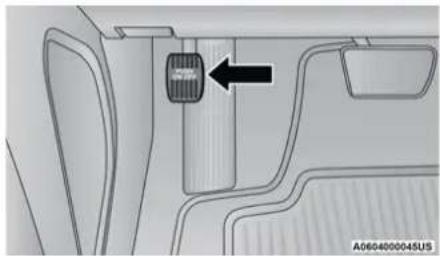
natural_image
Diagram of a vehicle interior with a highlighted vehicle component and directional arrow (no text or symbols)Parking Brake
When the parking brake is applied with the ignition switch in the ON/RUN position, the Brake Warning Light in the instrument cluster will illuminate.
NOTE:
- When the parking brake is applied and the transmission is placed in gear, the Brake Warning Light will flash. If vehicle speed is detected, a chime will sound to alert the driver. Fully release the parking brake before attempting to move the vehicle.
- This light only shows that the parking brake is applied. It does not show the degree of brake application.
When parking on a hill, it is important to turn the front wheels toward the curb on a downhill grade and away from the curb on an uphill grade. Apply the parking brake before placing the gear selector in PARK, otherwise the load on the transmission locking mechanism may make it difficult to move the gear selector out of PARK. The parking brake should always be applied whenever the driver is not in the vehicle.
WARNING!
- Never use the PARK position as a substitute for the parking brake. Always apply the parking brake fully when parked to guard against vehicle movement and possible injury or damage.
- When exiting the vehicle, always remove the key fob from the ignition and lock your vehicle.
- Never leave children alone in a vehicle, or with access to an unlocked vehicle. Allowing children to be in a vehicle unattended is dangerous for a number of reasons. A child or others could be seriously or fatally injured. Children should be warned not to touch the parking brake, brake pedal or the gear selector.
(Continued)
WARNING! (Continued)
- When exiting the vehicle, always make sure the keyless ignition node is in the OFF mode, remove the key fob from the vehicle and lock the vehicle.
- Do not leave the key fob in or near the vehicle or in a location accessible to children, and do not leave the ignition of a vehicle equipped with Keyless Enter-N-Go in the ACC or ON/RUN mode. A child could operate power windows, other controls, or move the vehicle.
- Be sure the parking brake is fully disengaged before driving; failure to do so can lead to brake failure and a collision.
- Always fully apply the parking brake when leaving your vehicle, or it may roll and cause damage or injury. Also be certain to leave the transmission in PARK. Failure to do so may allow the vehicle to roll and cause damage or injury.
CAUTION!
If the Brake Warning Light remains on with the parking brake released, a brake system malfunction is indicated. Have the brake system serviced by an authorized dealer immediately.
AUTOMATIC TRANSMISSION
NOTE:
You must press and hold the brake pedal while shifting out of PARK.
WARNING!
- Never use the PARK position as a substitute for the parking brake. Always apply the parking brake fully when exiting the vehicle to guard against vehicle movement and possible injury or damage.
- Your vehicle could move and injure you and others if it is not in PARK. Check by trying to move the transmission gear selector out of PARK with the brake pedal released. Make sure the transmission is in PARK before exiting the vehicle.
WARNING! (Continued)
- The transmission may not engage PARK if the vehicle is moving. Always bring the vehicle to a complete stop before shifting to PARK, and verify that the transmission gear position indicator solidly indicates PARK (P) without blinking. Ensure that the vehicle is completely stopped, and the PARK position is properly indicated, before exiting the vehicle.
- It is dangerous to shift out of PARK or NEUTRAL if the engine speed is higher than idle speed. If your foot is not firmly pressing the brake pedal, the vehicle could accelerate quickly forward or in reverse. You could lose control of the vehicle and hit someone or something. Only shift into gear when the engine is idling normally and your foot is firmly pressing the brake pedal.
(Continued)
(Continued)
WARNING! (Continued)
- Unintended movement of a vehicle could injure those in or near the vehicle. As with all vehicles, you should never exit a vehicle while the engine is running. Before exiting a vehicle, always come to a complete stop, then apply the parking brake, shift the transmission into PARK, and turn the ignition OFF. When the ignition is in the OFF mode, the transmission is locked in PARK, securing the vehicle against unwanted movement.
- When exiting the vehicle, always make sure the ignition is in the OFF mode, remove the key fob from the vehicle, and lock the vehicle.
- Never leave children alone in a vehicle, or with access to an unlocked vehicle. Allowing children to be in a vehicle unattended is dangerous for a number of reasons. A child or others could be seriously or fatally injured. Children should be warned not to touch the parking brake, brake pedal or the transmission gear selector.
(Continued)
WARNING! (Continued)
- Do not leave the key fob in or near the vehicle (or in a location accessible to children), and do not leave the ignition in the ACC or ON/RUN mode. A child could operate power windows, other controls, or move the vehicle.
CAUTION!
- Shift into or out of PARK or REVERSE only after the vehicle has come to a complete stop.
- Do not shift between PARK, REVERSE, NEUTRAL, or DRIVE when the engine is above idle speed.
- Before shifting into any gear, make sure your foot is firmly pressing the brake pedal.
IGNITION PARK INTERLOCK
This vehicle is equipped with an Ignition Park Interlock which requires the transmission to be in PARK before the ignition can be turned to the OFF mode. This helps the driver avoid inadvertently leaving the vehicle without placing the transmission in PARK. This system also locks the transmission in PARK whenever the ignition is in the OFF mode.
NOTE:
The transmission is NOT locked in PARK when the ignition is in the ACC mode (even though the engine will be off). Ensure that the transmission is in PARK, and the ignition is OFF (not in ACC mode) before exiting the vehicle.
This vehicle is equipped with BTSI that holds the transmission gear selector in PARK unless the brakes are applied. To shift the transmission out of PARK, the engine must be running and the brake pedal must be pressed. The brake pedal must also be pressed to shift from NEUTRAL into DRIVE or REVERSE when the vehicle is stopped or moving at low speeds.
The transmission is controlled using a rotary electronic gear selector located on the center console. The transmission gear range (PRNDL/S) is displayed both above the gear selector and in
the instrument cluster. To select a gear range, simply rotate the gear selector. To access the L or S position, push down on the gear selector and then rotate it. You must also press the brake pedal to shift the transmission out of PARK (or NEUTRAL, when the vehicle is stopped or moving at low speeds). To shift past multiple gear ranges at once (such as PARK to DRIVE), simply rotate the gear selector to the appropriate detent. Select the DRIVE range for normal driving.
NOTE:
In the event of a mismatch between the gear selector position and the actual transmission gear (for example, driver selects PARK while driving), the position indicator will blink continuously until the selector is returned to the proper position, or the requested shift can be completed.
The electronically-controlled transmission adapts its shift schedule based on driver inputs, along with environmental and road conditions. The transmission electronics are self-calibrating; therefore, the first few shifts on a new vehicle may be somewhat abrupt. This is a normal condition, and precision shifts will develop within a few hundred miles (kilometers).
Only shift from DRIVE to PARK or REVERSE when the accelerator pedal is released and the vehicle is stopped. Be sure to keep your foot on the brake pedal when shifting between these gears.
Standard Gear Selector
The standard transmission gear selector has PARK, REVERSE, NEUTRAL, DRIVE, and LOW shift positions. Using the LOW position manually downshifts the transmission to a lower gear based on vehicle speed.
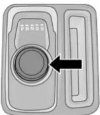
natural_image
Diagram of a device tray with labeled 'PANDS' and an arrow pointing to a circular component (no text or symbols beyond labels)A0606000088US
Premium Gear Selector
Premium Gear Selector With AutoStick
The premium transmission gear selector provides PARK, REVERSE, NEUTRAL, DRIVE, and SPORT shift positions. Manual shifts can be made using the AutoStick shift control (shift paddles mounted on the steering wheel). Pressing the shift paddles (-/+) while in the DRIVE or SPORT position will manually select the transmission gear, and will display the current gear in the instrument cluster as 1, 2, 3, etc ↩ page 104.
Gear Ranges
Do not press the accelerator pedal when shifting from PARK or NEUTRAL into another gear range.
NOTE:
After selecting any gear range, wait a moment to allow the selected gear to engage before accelerating. This is especially important when the engine is cold.
PARK (P)
This range supplements the parking brake by locking the transmission. The engine can be started in this range. Never attempt to use PARK while the vehicle is in motion. Apply the parking brake when exiting the vehicle in this range.
When parking on a level surface, you may shift the transmission into PARK first, and then apply the parking brake.
When parking on a hill, apply the parking brake before shifting the transmission to PARK. As an added precaution, turn the front wheels toward the curb on a downhill grade and away from the curb on an uphill grade.
When exiting the vehicle, always:
- Apply the parking brake.
- Shift the transmission into PARK.
- Turn the ignition OFF.
- Remove the key fob from the vehicle.
WARNING!
- Never use the PARK position as a substitute for the parking brake. Always apply the parking brake fully when exiting the vehicle to guard against vehicle movement and possible injury or damage.
- Your vehicle could move and injure you and others if it is not in PARK. Check by trying to move the transmission gear selector out of PARK with the brake pedal released. Make sure the transmission is in PARK before exiting the vehicle.
- The transmission may not engage PARK if the vehicle is moving. Always bring the vehicle to a complete stop before shifting to PARK, and verify that the transmission gear position indicator solidly indicates PARK (P) without blinking. Ensure that the vehicle is completely stopped, and the PARK position is properly indicated, before exiting the vehicle.
(Continued)
WARNING! (Continued)
- It is dangerous to shift out of PARK or NEUTRAL if the engine speed is higher than idle speed. If your foot is not firmly pressing the brake pedal, the vehicle could accelerate quickly forward or in reverse. You could lose control of the vehicle and hit someone or something. Only shift into gear when the engine is idling normally and your foot is firmly pressing the brake pedal.
- Unintended movement of a vehicle could injure those in or near the vehicle. As with all vehicles, you should never exit a vehicle while the engine is running. Before exiting a vehicle, always come to a complete stop, then apply the parking brake, shift the transmission into PARK, and turn the ignition OFF. When the ignition is in the OFF mode, the transmission is locked in PARK, securing the vehicle against unwanted movement.
- When exiting the vehicle, always make sure the ignition is in the OFF mode, remove the key fob from the vehicle, and lock the vehicle.
(Continued)
WARNING! (Continued)
- Never leave children alone in a vehicle, or with access to an unlocked vehicle. Allowing children to be in a vehicle unattended is dangerous for a number of reasons. A child or others could be seriously or fatally injured. Children should be warned not to touch the parking brake, brake pedal or the transmission gear selector.
- Do not leave the key fob in or near the vehicle (or in a location accessible to children), and do not leave the ignition in the ACC or ON/RUN mode. A child could operate power windows, other controls, or move the vehicle.
CAUTION!
- Before moving the transmission gear selector out of PARK, you must start the engine, and also press the brake pedal. Otherwise, damage to the gear selector could result.
- DO NOT race the engine when shifting from PARK or NEUTRAL into another gear range, as this can damage the drivetrain.
The following indicators should be used to ensure that you have properly engaged the transmission into the PARK position:
- Look at the transmission gear position display and verify that it indicates the PARK position, and is not blinking.
- With the brake pedal released, verify that the gear selector will not move out of PARK.
REVERSE (R)
This range is for moving the vehicle backward. Shift into REVERSE only after the vehicle has come to a complete stop.
NEUTRAL (N)
Use this range when the vehicle is standing for prolonged periods with the engine running. Apply the parking brake and shift the transmission into PARK if you must exit the vehicle.
WARNING!
Do not coast in NEUTRAL and never turn off the ignition to coast down a hill. These are unsafe practices that limit your response to changing traffic or road conditions. You might lose control of the vehicle and have a collision.
CAUTION!
Towing the vehicle, coasting, or driving for any other reason with the transmission in NEUTRAL can cause severe transmission damage.
For "Recreational Towing" → page 140
For "Towing A Disabled Vehicle" ↩ page 225
DRIVE (D)
This range should be used for most city and highway driving. It provides the smoothest upshifts and downshifts, and the best fuel economy. The transmission automatically upshifts through all forward gears. The DRIVE position provides optimum driving characteristics under all normal operating conditions.
When frequent transmission shifting occurs (such as when operating the vehicle under heavy loading conditions, in hilly terrain, traveling into strong head winds, or while towing a heavy trailer), use the AutoStick shift control (if equipped) to select a lower gear → page 104. Under these conditions, using a lower gear will improve performance and extend transmission life by reducing excessive shifting and heat buildup.
During extremely cold temperatures (-22°F [-30°C] or below), transmission operation may be modified depending on engine and transmission temperature as well as vehicle speed. Normal operation will resume once the transmission temperature has risen to a suitable level.
SPORT (S) — If Equipped
This mode alters the transmission's automatic shift schedule for sportier driving. Upshift speeds are increased to make full use of available engine power.
To access SPORT mode, push down on the gear selector and rotate it fully clockwise, or push the SPORT button in the center stack.
LOW (L) — If Equipped
Use this range for engine braking when descending very steep grades. In this range, the transmission will downshift for increased engine braking. To access the LOW position, push down on the gear selector and rotate it fully clockwise.
Transmission Limp Home Mode
Transmission function is monitored electronically for abnormal conditions. If a condition is detected that could result in transmission damage, Transmission Limp Home Mode is activated. In this mode, the transmission may operate only in certain gears, or may not shift at all. Vehicle performance may be severely degraded and the engine may stall. In some situations, the transmission may not re-engage if the engine is turned off and restarted. The Malfunction Indicator Light (MIL) may be illuminated. A message in the instrument cluster will inform the driver of the more serious conditions, and indicate what actions may be necessary.
In the event of a momentary problem, the transmission can be reset to regain all forward gears by performing the following steps:
NOTE:
In cases where the instrument cluster message indicates the transmission may not re-engage after engine shutdown, perform this procedure only in a desired location (preferably, at an authorized dealer).
- Stop the vehicle.
-
Shift the transmission into PARK, if possible. If not, shift the transmission to NEUTRAL.
-
Push and hold the ignition switch until the engine turns off.
- Wait approximately 30 seconds.
- Restart the engine.
- Shift into the desired gear range. If the problem is no longer detected, the transmission will return to normal operation.
NOTE:
Even if the transmission can be reset, we recommend that you visit an authorized dealer at your earliest possible convenience. An authorized dealer has diagnostic equipment to assess the condition of your transmission.
If the transmission cannot be reset, authorized dealer service is required.
AutoStick — If Equipped
AutoStick is a driver-interactive transmission feature providing manual shift control, giving you more control of the vehicle. AutoStick allows you to maximize engine braking, eliminate undesirable upshifts and downshifts, and improve overall vehicle performance.
This system can also provide you with more control during passing, city driving, cold slippery conditions, mountain driving, trailer towing, and many other situations.
Operation
When the transmission is in DRIVE or SPORT mode, it will operate automatically, shifting between the eight available gears. To engage AutoStick, simply tap one of the steering wheel-mounted shift paddles (+/-) while in DRIVE or SPORT mode. In DRIVE mode, this will activate a temporary AutoStick mode. The transmission will revert back to normal operation after a period of time, depending on accelerator pedal activity. When the transmission gear selector is in the SPORT position, tapping either shift paddle will activate "permanent" AutoStick mode. The transmission will remain in AutoStick mode until the driver deliberately disables AutoStick (as described below). Tapping (-) to enter AutoStick will downshift the transmission to the next lower gear, while using (+) to enter AutoStick will retain the current gear. When AutoStick is active, the current transmission gear is displayed in the instrument cluster.
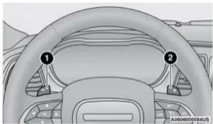
natural_image
Interior view of a car dashboard with steering wheel and two numbered components (no text or symbols visible)Paddle Shifters
1 – Shift Paddle Downshift
2 – Shift Paddle Upshift
In AutoStick mode, the transmission will shift up or down when (+/-) is manually selected by the driver, unless an engine lugging or overspeed condition would result. It will remain in the selected gear until another upshift or downshift is chosen, except as described below.
- If AutoStick is engaged while in DRIVE mode, the transmission will automatically shift up when maximum engine speed is reached. If the accelerator is fully pressed, the transmission will downshift when possible (based on current vehicle speed and gear). Lack of accelerator pedal activity will cause the transmission to revert to automatic operation.
- If AutoStick is engaged while the transmission gear selector is in the SPORT position, manual gear selection will be maintained until the gear selector is returned to DRIVE, or as described below. The transmission will not upshift automatically at redline in this mode, nor will downshifts be obtained if the accelerator pedal is pressed to the floor.
- In either DRIVE or SPORT mode, the transmission will automatically downshift as the vehicle slows (to prevent engine lugging) and will display the current gear.
- The transmission will automatically downshift to FIRST gear when coming to a stop. After a stop, the driver should manually upshift (+) the transmission as the vehicle is accelerated.
- You can start out, from a stop, in FIRST or SECOND gear. Tapping (+) at a stop will allow starting in SECOND gear. Starting out in SECOND gear can be helpful in snowy or icy conditions.
- If a requested downshift would cause the engine to over-speed, that shift will not occur.
- The system will ignore attempts to upshift at too low of a vehicle speed.
106 STARTING AND OPERATING
- Holding the (-) paddle pressed will downshift the transmission to the lowest gear possible at the current speed.
● Transmission shifting will be more noticeable when AutoStick is enabled. - The system may revert to automatic shift mode if a fault or overheat condition is detected.
To disengage AutoStick mode, press and hold the (+) shift paddle until "D" or "S" is once again indicated in the instrument cluster. Shifting out of SPORT mode will also disable AutoStick. You can shift in or out of AutoStick mode at any time without taking your foot off the accelerator pedal.
WARNING!
Do not downshift for additional engine braking on a slippery surface. The drive wheels could lose their grip and the vehicle could skid, causing a collision or personal injury.
SPORT MODE — IF EQUIPPED
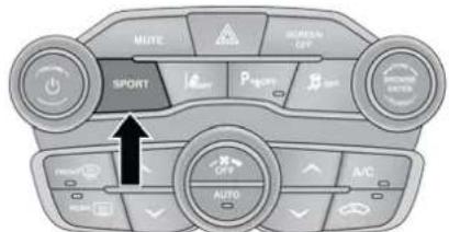
text_image
MUTE SUPPORT P AUTO AVC A/C RESET OFF AUTO AIR GREEN LEFT GREEN AUTO AIRSPORT Mode Button
If your vehicle is equipped with SPORT mode, this mode is a configuration set up for typical enthusiast driving. The engine, transmission and steering systems are all set to their SPORT settings. SPORT mode will provide improved throttle response and modified shifting for an enhanced driving experience, as well the greatest amount of steering feel. This mode may be activated and deactivated by pushing the SPORT button on the instrument panel switch bank.
FUEL SAVER TECHNOLOGY 5.7L ONLY — IF EQUIPPED
This feature offers improved fuel economy by shutting off four of the engine's eight cylinders during light load and cruise conditions. The system is automatic with no driver inputs or additional driving skills required.
NOTE:
This system may take some time to return to full functionality after a battery disconnect.
POWER STEERING
The Electric Power Steering system will give you good vehicle response and increased ease of maneuverability in tight spaces. The system will vary its assist to provide light efforts while parking and good feel while driving. If the electric steering system experiences a fault that prevents it from providing assist, you will still have the ability to steer the vehicle manually.
WARNING!
Continued operation with reduced assist could pose a safety risk to yourself and others. Service should be obtained as soon as possible.
Alternate electric power steering efforts can be selected through the Uconnect system page 144.

If the Electric Power Steering Fault Warning Light is displayed and the "SERVICE POWER STEERING" or the "POWER STEERING ASSIST OFF -
SERVICE SYSTEM" message is displayed within the instrument cluster display, this indicates the vehicle needs to be taken to the dealer for service → page 82.
NOTE:
- Even if the power steering assistance is no longer operational, it is still possible to steer the vehicle. Under these conditions there will be a substantial increase in steering effort, especially at low speeds and during parking maneuvers.
- If the condition persists, see an authorized dealer for service.
If the Electric Power Steering Fault Warning Light is displayed and the "POWER STEERING SYSTEM OVER TEMP" message is displayed on the instrument cluster screen, they indicate that extreme steering maneuvers may have occurred which caused an over temperature condition in the
power steering system. Once driving conditions are safe, pull over and let the vehicle idle for a few moments until the Electric Power Steering Fault Warning Light and message turn off.
CRUISE CONTROL SYSTEMS — IF EQUIPPED
Your vehicle may be equipped with the Cruise Control system, or the Adaptive Cruise Control (ACC) system:
- Cruise Control for cruising at a constant preset speed.
- Adaptive Cruise Control (ACC) for maintaining a set distance between you and the vehicle ahead using Fixed Speed Cruise Control to automatically adjust the preset speed.
NOTE:
In vehicles equipped with ACC, if an ACC distance is not set, Fixed Speed Cruise Control will not detect vehicles directly ahead of you. Always be aware of the mode selected.
CRUISE CONTROL — IF EQUIPPED
When engaged, the Cruise Control system takes over accelerator operations at speeds greater than 25 mph (40 km/h), or 20 mph (32 km/h) depending on engine size and axle ratio.
The Cruise Control buttons are located on the right side of the steering wheel.
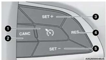
text_image
SET+ CANC RES SET- A0626000046USCruise Control Buttons
1 - On/Off
2 - CANC/Cancel
3 - SET (+)/Accelerate
4 - RES/Resume
5 - SET (-)/Decelerate
NOTE:
In order to ensure proper operation, the Cruise Control system has been designed to shut down if multiple speed control functions are operated at the same time. If this occurs, the Cruise Control system can be reactivated by pushing the Cruise Control on/off button and resetting the desired vehicle set speed.
To Activate
Push the on/off button to activate the Cruise Control. "CRUISE CONTROL READY" will appear in the instrument cluster display to indicate the Cruise Control is on. To turn the system off, push the on/off button a second time. "CRUISE CONTROL OFF" will appear in the instrument cluster display to indicate the Cruise Control is off. The system should be turned off when not in use.
WARNING!
Leaving the Cruise Control system on when not in use is dangerous. You could accidentally set the system or cause it to go faster than you want. You could lose control and have an accident. Always leave the system OFF when you are not using it.
To Set A Desired Speed
Turn the Cruise Control on. When the vehicle has reached the desired speed, push and release the SET (+) or SET (-) button. Release the accelerator and the vehicle will operate at the selected speed. Once a speed has been set, a message "CRUISE CONTROL SET TO MPH (km/h)" will appear indicating the set speed. A cruise indicator lamp, along with set speed will also appear and stay on in the instrument cluster when the speed is set.
To Vary The Speed Setting
To Increase Or Decrease The Set Speed
When the Cruise Control is set, you can increase speed by pushing the SET (+) button, or decrease speed by pushing the SET (-) button.
U.S. Speed (mph)
- Pushing the SET (+), or SET (-) button once will result in a 1 mph speed adjustment. Each subsequent tap of the button results in an adjustment of 1 mph.
- If the button is continually pushed, the set speed will continue to adjust until the button is released, then the new set speed will be established.
Metric Speed (km/h)
- Pushing the SET (+), or SET (-) button once will result in a 1 km/h speed adjustment. Each subsequent tap of the button results in an adjustment of 1 km/h.
- If the button is continually pushed, the set speed will continue to adjust until the button is released, then the new set speed will be established.
To Accelerate For Passing
Press the accelerator as you would normally. When the pedal is released, the vehicle will return to the set speed.
Using Cruise Control On Hills
The transmission may downshift on hills to maintain the vehicle set speed.
The Cruise Control system maintains speed up and down hills. A slight speed change on moderate hills is normal. On steep hills, a greater speed loss or gain may occur so it may be preferable to drive without Cruise Control.
WARNING!
Cruise Control can be dangerous where the system cannot maintain a constant speed. Your vehicle could go too fast for the conditions, and you could lose control and have an accident. Do not use Cruise Control in heavy traffic or on roads that are winding, icy, snow-covered or slippery.
To Resume Speed
To resume a previously set speed, push the RES button and release. Resume can be used at any speed above 20 mph (32 km/h).
To Deactivate
A tap on the brake pedal, pushing the CANC button, or normal brake pressure will deactivate the Cruise Control system without erasing the set speed from memory.
The following conditions will also deactivate the Cruise Control without erasing the set speed from memory:
● Vehicle parking brake is applied
- Stability event occurs
• Gear selector is moved out of DRIVE
• Engine overspeed occurs
Pushing the on/off button or placing the ignition in the OFF position erases the set speed from memory.
ADAPTIVE CRUISE CONTROL (ACC)—IF EQUIPPED
Adaptive Cruise Control (ACC) increases the driving convenience provided by Cruise Control while traveling on highways and major roadways. However, it is not a safety system and not designed to prevent collisions. The Cruise Control function performs differently ➤ page 107.
ACC will allow you to keep Cruise Control engaged in light to moderate traffic conditions without the constant need to reset your Cruise Control. ACC utilizes a radar sensor and a forward facing camera designed to detect a vehicle directly ahead of you.
NOTE:
- If the ACC sensor detects a vehicle ahead, ACC will apply limited braking or acceleration (not to exceed the original set speed) automatically to maintain a preset following distance, while matching the speed of the vehicle ahead.
- Any chassis/suspension or tire size modifications to the vehicle will affect the performance of the Adaptive Cruise Control and Forward Collision Warning systems.
- Fixed Speed Cruise Control alone (an ACC distance not set) will not detect vehicles directly ahead of you. Always be aware of the mode selected ➔ page 298.
WARNING!
- Adaptive Cruise Control (ACC) is a convenience system. It is not a substitute for active driver involvement. It is always the driver's responsibility to be attentive of road, traffic, and weather conditions, vehicle speed, distance to the vehicle ahead; and, most importantly, brake operation to ensure safe operation of the vehicle under all road conditions. Your complete attention is always required while driving to maintain safe control of your vehicle. Failure to follow these warnings can result in a collision and death or serious personal injury.
(Continued)
WARNING! (Continued)
- The ACC system:
- Does not react to pedestrians, oncoming vehicles, and stationary objects (e.g., a stopped vehicle in a traffic jam or a disabled vehicle).
- Cannot take street, traffic, and weather conditions into account, and may be limited upon adverse sight distance conditions.
- Does not always fully recognize complex driving conditions, which can result in wrong or missing distance warnings.
- Will bring the vehicle to a complete stop while following the vehicle in front and hold the vehicle for two seconds in the stop position. If the vehicle in front does not start moving within two seconds the ACC system will display a message that the system will release the brakes and that the brakes must be applied manually. An audible chime will sound when the brakes are released.
WARNING! (Continued)
You should switch off the ACC system:
- When driving in fog, heavy rain, heavy snow, sleet, heavy traffic, and complex driving situations (i.e., in highway construction zones).
- When entering a turn lane or highway off ramp; when driving on roads that are winding, icy, snow-covered, slippery, or have steep uphill or downhill slopes.
- When towing a trailer up or down steep slopes.
- When circumstances do not allow safe driving at a constant speed.
(Continued)
Adaptive Cruise Control (ACC) Operation
The buttons on the right side of the steering wheel operate the ACC system.
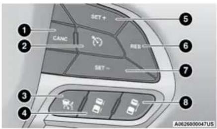
text_image
SET + CANC ADD SET - A0626000047USAdaptive Cruise Control Buttons
1 - CANC/Cancel
2 — Fixed Speed Cruise Control On/Off
3 — Adaptive Cruise Control (ACC) On/Off
4 – Distance Setting Decrease
5 - SET (+)/Accel
6 - RES/Resume
7 - SET (-)/Decel
8 – Distance Setting Increase
Adaptive Cruise Control (ACC) Menu
The instrument cluster display will show the current ACC system settings. The information it displays depends on ACC system status.
Push the ACC on/off button until one of the following appears in the instrument cluster display:
Adaptive Cruise Control Off
When ACC is deactivated, the display will read "Adaptive Cruise Control Off."
Adaptive Cruise Control Ready
When ACC is activated, but the vehicle speed setting has not been selected, the display will read "Adaptive Cruise Control Ready."
Adaptive Cruise Control Set
When the SET (+) or the SET (-) button is pushed, the display will read "ACC SET."
When ACC is set, the set speed will show in the instrument cluster display.
The ACC screen may display once again if any of the following ACC activity occurs:
- System Cancel
-
Driver Override
-
System Off
- ACC Proximity Warning
- ACC Unavailable Warning
The instrument cluster display will return to the last display selected after five seconds of no ACC display activity.
Activating Adaptive Cruise Control (ACC)
The minimum set speed for the ACC system is 20 mph (32 km/h).
When the system is turned on and in the ready state, the instrument cluster displays "ACC Ready."
When the system is off, the instrument cluster display will read "Adaptive Cruise Control (ACC) Off."
NOTE:
You cannot engage ACC under the following conditions:
- When the brakes are applied
- When the parking brake is applied
- When the automatic transmission is in PARK, REVERSE or NEUTRAL
112 STARTING AND OPERATING
- When the vehicle speed is below the minimum speed range
- When the brakes are overheated
- When the driver's door is open at low speeds
- When the driver's seat belt is unbuckled at low speeds
- When there is a stationary vehicle in front of your vehicle in close proximity
To Activate/Deactivate
Push and release the Adaptive Cruise Control (ACC) on/off button. The ACC menu in the instrument cluster displays "ACC Ready."
To turn the system off, push and release the Adaptive Cruise Control (ACC) on/off button again. At this time, the system will turn off and the instrument cluster displays “Adaptive Cruise Control (ACC) Off.”
WARNING!
Leaving the Adaptive Cruise Control (ACC) system on when not in use is dangerous. You could accidentally set the system or cause it to go faster than you want. You could lose control and have a collision. Always leave the system off when you are not using it.
To Set A Desired ACC Speed
When the vehicle reaches the speed desired, push the SET (+) button or the SET (-) button and release. The instrument cluster display will show the set speed.
NOTE:
Fixed Speed Cruise Control can be used without an ACC distance set. To change between the different modes, push the ACC on/off button which turns the ACC and the Fixed Speed Cruise Control off. Pushing the Fixed Speed Cruise Control on/off button will result in turning on (changing to) Fixed Speed Cruise Control mode.
WARNING!
In the Normal (Fixed Speed) Cruise Control mode, the system will not react to vehicles ahead. In addition, the proximity warning does not activate and no alarm will sound even if you are too close to the vehicle ahead since neither the presence of the vehicle ahead nor the vehicle-to-vehicle distance is detected. Be sure to maintain a safe distance between your vehicle and the vehicle ahead. Always be aware which mode is selected.
If ACC is set when the vehicle speed is below 20 mph (32 km/h), the set speed will default to 20 mph (20 km/h).
NOTE:
Fixed Speed Cruise Control cannot be set below 20 mph (32 km/h).
If either system is set when the vehicle speed is above 20 mph (32 km/h), the set speed shall be the current speed of the vehicle.
NOTE:
- Keeping your foot on the accelerator pedal can cause the vehicle to continue to accelerate beyond the set speed. If this occurs, the message "DRIVER OVERRIDE" will display in the instrument cluster display.
- If you continue to accelerate beyond the set speed while an ACC distance is also set, the system will not be controlling the distance between your vehicle and the vehicle ahead. The vehicle speed will only be determined by the position of the accelerator pedal.
To Cancel
The following conditions cancel the ACC or Fixed Speed Cruise Control systems:
• The brake pedal is applied
• The CANC button is pushed
● The Anti-Lock Brake System (ABS) activates
- The gear selector is removed from the DRIVE position
- The braking temperature exceeds normal range (overheated)
- The Electronic Stability Control/Traction Control System (ESC/TCS) activates
● The vehicle parking brake is applied
The following conditions will only cancel the ACC system:
- Driver seat belt is unbuckled at low speeds
- Driver door is opened at low speeds
To Turn Off
The system will turn off and erase the set speed in memory if:
- The Adaptive Cruise Control (ACC) on/off button is pushed
- The Fixed Speed Cruise Control on/off button is pushed
- The ignition is placed in the OFF position.
To Resume
If there is a set speed in memory, push the RES (resume) button and remove your foot from the accelerator pedal. The instrument cluster display will show the last set speed.
Resume can be used at any speed above 20 mph (32 km/h) when only Fixed Speed Cruise Control is being used.
Resume can be used at any speed above 0 mph (0 km/h) when ACC is active.
WARNING!
The Resume function should only be used if traffic and road conditions permit. Resuming a set speed that is too high or too low for prevailing traffic and road conditions could cause the vehicle to accelerate or decelerate too sharply for safe operation. Failure to follow these warnings can result in a collision and death or serious personal injury.
To Vary The Speed Setting
To Increase Or Decrease The Set Speed
After setting a speed, you can increase the set speed by pushing the SET (+) button, or decrease speed by pushing the SET (-) button.
U.S. Speed (mph)
- Pushing the SET (+), or SET (-) button once will result in a 1 mph speed adjustment. Each subsequent tap of the button results in an adjustment of 1 mph.
- If the button is continually pushed, the set speed will continue to adjust in 5 mph increments until the button is released. The new set speed is reflected in the instrument cluster display.
Metric Speed (km/h)
- Pushing the SET (+), or SET (-) button once will result in a 1 km/h speed adjustment. Each subsequent tap of the button results in an adjustment of 1 km/h.
- If the button is continually pushed, the set speed will continue to adjust in 10 km/h increments until the button is released. The new set speed is reflected in the instrument cluster display.
NOTE:
When you override and push the SET (+) button or SET (-) buttons, the new set speed will be the current speed of the vehicle.
When An ACC Distance Is Also Set:
NOTE:
- When you use the SET (-) button to decelerate, if the engine's braking power does not slow the vehicle sufficiently to reach the set speed, the brake system will automatically slow the vehicle.
- The ACC system decelerates the vehicle to a full stop when following a vehicle in front. When you have ACC active and follow a vehicle in front to a standstill, after two seconds you will either have to push the RES (resume) button, or apply the accelerator pedal to reengage the ACC to the existing set speed.
- The ACC will bring the vehicle to a complete stop while following a vehicle in front and hold the vehicle for two seconds in the stop position. If the vehicle in front does not start moving within two seconds, the ACC system will display a message that the system will release the brakes and that the brakes must be applied manually. An audible chime will sound when the brakes are released.
- The ACC system maintains set speed when driving uphill and downhill. However, a slight speed change on moderate hills is normal. In addition, downshifting may occur while climbing uphill or descending downhill. This is normal operation and necessary to maintain set speed. When driving uphill and downhill, the ACC system will cancel if the braking temperature exceeds normal range (overheated).
Setting The Following Distance In ACC
The specified following distance for ACC can be set by varying the distance setting between four bars (longest), three bars (long), two bars (medium) and one bar (short). Using this distance setting and the vehicle speed, ACC calculates and sets the distance to the vehicle ahead. This distance setting displays in the instrument cluster display.
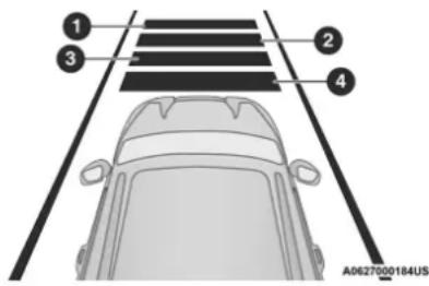
text_image
① ③ ② ④ A0627000184USDistance Settings
1 – Longest Distance Setting (Four Bars)
2 — Long Distance Setting (Three Bars)
3 - Medium Distance Setting (Two Bars)
4 – Short Distance Setting (One Bar)
To increase the distance setting, push the Distance Setting Increase button and release. Each time the button is pushed, the distance setting increases by one bar (longer).
To decrease the distance setting, push the Distance Setting Decrease button and release. Each time the button is pushed, the distance setting decreases by one bar (shorter).
If there is no vehicle ahead, the vehicle will maintain the set speed. If a slower moving vehicle is detected in the same lane, the instrument cluster display will show the ACC Set With Target Detected Indicator Light, and the system will adjust the vehicle speed automatically to maintain the distance setting, regardless of the set speed.
The vehicle will then maintain the set distance until:
- The vehicle ahead accelerates to a speed above the set speed.
- The vehicle ahead moves out of your lane or view of the sensor.
- The distance setting is changed.
- The system disengages ➤ page 112.
The maximum braking applied by ACC is limited; however, the driver can always apply the brakes manually, if necessary.
NOTE:
The brake lights will illuminate whenever the ACC system applies the brakes.
A Proximity Warning will alert the driver if ACC predicts that its maximum braking level is not sufficient to maintain the set distance. If this occurs, a visual alert “BRAKE” will flash in the instrument cluster display and a chime will sound while ACC continues to apply its maximum braking capacity.
NOTE:
The “BRAKE!” screen in the instrument cluster display is a warning for the driver to take action and does not necessarily mean that the Forward Collision Warning system is applying the brakes autonomously.
Overtake Aid
When driving with ACC engaged and following a vehicle, the system will provide an additional acceleration up to the ACC set speed to assist in passing the vehicle. This additional acceleration is triggered when the driver utilizes the left turn
signal (Lane Change Assist feature included) and will only be active when passing on the left hand side. Switching lanes will not impact the ACC system if the driver is already traveling at the set speed.
ACC Operation At Stop
In the event that the ACC system brings your vehicle to a standstill while following the vehicle in front, your vehicle will resume motion without any driver interaction if the vehicle in front starts moving within two seconds of your vehicle coming to a standstill.
If the vehicle in front does not start moving within two seconds of your vehicle coming to a standstill, the ACC with Stop system will cancel and the brakes will release. A cancel message will display on the instrument cluster display and produce a warning chime. Driver intervention will be required at this moment.
While ACC with Stop is holding your vehicle at a standstill, if the driver seat belt is unbuckled or the driver door is opened, the ACC with Stop system will cancel and the brakes will release. A cancel message will display on the instrument cluster display and produce a warning chime. Driver intervention will be required at this moment.
WARNING!
When the ACC system is resumed, the driver must ensure that there are no pedestrians, vehicles or objects in the path of the vehicle. Failure to follow these warnings can result in a collision and death or serious personal injury.
Display Warnings And Maintenance
"Wipe Front Radar Sensor In Front Of Vehicle" Warning
The "ACC/FCW Unavailable Wipe Front Radar Sensor" warning will display and a chime will indicate when conditions temporarily limit system performance.
This most often occurs at times of poor visibility, such as in snow or heavy rain. The ACC system may also become temporarily blinded due to obstructions, such as mud, dirt or ice. In these cases, the instrument cluster will display the above message and the system will deactivate.
This message can sometimes be displayed while driving in highly reflective areas (i.e. ice and snow, or tunnels with reflective tiles). The ACC system will recover after the vehicle has left these areas. Under rare conditions, when the radar is not tracking any vehicles or objects in its path this warning may temporarily occur.
NOTE:
If the "ACC/FCW Unavailable Wipe Front Radar Sensor" warning is active, Fixed Speed Cruise Control is still available.
If weather conditions are not a factor, the driver should examine the sensor. It may require cleaning or removal of an obstruction. The sensor is located in the center of the vehicle behind the lower grille.
To keep the ACC system operating properly, it is important to note the following maintenance items:
- Always keep the sensor clean. Carefully wipe the sensor lens with a soft cloth. Be careful not to damage the sensor lens.
-
Do not remove any screws from the sensor. Doing so could cause an ACC system malfunction or failure and require a sensor realignment.
-
If the sensor or front end of the vehicle is damaged due to a collision, see an authorized dealer for service.
- Do not attach or install any accessories near the sensor, including transparent material or aftermarket grilles. Doing so could cause an ACC system failure or malfunction.
When the condition that deactivated the system is no longer present, the system will return to the “Adaptive Cruise Control Off” state and will resume function by simply reactivating it.
NOTE:
- If the "ACC/FCW Unavailable Wipe Front Radar Sensor" message occurs frequently (e.g. more than once on every trip) without any snow, rain, mud, or other obstruction, have the radar sensor realigned at an authorized dealer.
- Installing a snow plow, front-end protector, an aftermarket grille or modifying the grille is not recommended. Doing so may block the sensor and inhibit ACC/FCW operation.
"Clean Front Windshield" Warning
The “ACC/FCW Limited Functionality Clean Front Windshield” warning will display and also a chime will indicate when conditions temporarily limit system performance. This most often occurs at times of poor visibility, such as in snow or heavy rain and fog. The ACC system may also become temporarily blinded due to obstructions, such as mud, dirt, or ice on windshield and fog on the inside of glass. In these cases, the instrument cluster display will display “ACC/FCW Limited Functionality Clean Front Windshield” and the system will have degraded performance.
This message can sometimes be displayed while driving in adverse weather conditions. The ACC/FCW system will recover after the vehicle has left these areas. Under rare conditions, when the camera is not tracking any vehicles or objects in its path this warning may temporarily occur.
If weather conditions are not a factor, the driver should examine the windshield and the camera located on the back side of the inside rearview mirror. They may require cleaning or removal of an obstruction.
When the condition that created limited functionality is no longer present, the system will return to full functionality.
NOTE:
If the "ACC/FCW Limited Functionality Clean Front Windshield" message occurs frequently (e.g. more than once on every trip) without any snow, rain, mud, or other obstruction, have the windshield and forward facing camera inspected at an authorized dealer.
Service ACC/FCW Warning
If the system turns off, and the instrument cluster displays “ACC/FCW Unavailable Service Required” or “Cruise/FCW Unavailable Service Required”, there may be an internal system fault or a temporary malfunction that limits ACC functionality. Although the vehicle is still drivable under normal conditions, ACC will be temporarily unavailable. If this occurs, try activating ACC again later, following an ignition cycle. If the problem persists, see an authorized dealer.
Precautions While Driving With ACC
In certain driving situations, ACC may have detection issues. In these cases, ACC may brake late or unexpectedly. The driver needs to
118 STARTING AND OPERATING
stay alert and may need to intervene. The following are examples of these types of situations:
Towing A Trailer
Towing a trailer is not recommended when using ACC.
Offset Driving
ACC may not detect a vehicle in the same lane that is offset from your direct line of travel, or a vehicle merging in from a side lane. There may not be sufficient distance to the vehicle ahead. The offset vehicle may move in and out of the line of travel, which can cause your vehicle to brake or accelerate unexpectedly.
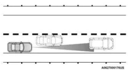
natural_image
Top-down diagram of three cars on a road with dashed lane lines (no text or symbols)Offset Driving Condition Example
Turns And Bends
When driving on a curve with ACC engaged, the system may decrease the vehicle speed and acceleration for stability reasons, with no target vehicle detected. Once the vehicle is out of the curve the system will resume your original set speed. This is a part of normal ACC system functionality.
NOTE:
On tight turns ACC performance may be limited. The driver must maintain control of the vehicle, remain alert, and be ready to apply the brakes if needed.
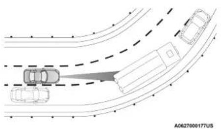
natural_image
Diagram showing vehicle collision with a truck on a multi-lane road, no text or symbols presentTurn Or Bend Example
Using ACC On Hills
When driving on hills, ACC may not detect a vehicle in your lane. Depending on the speed, vehicle load, traffic conditions, and the steepness of the hills, ACC performance may be limited.
NOTE:
The driver must maintain control of the vehicle, remain alert, and be ready to apply the brakes if needed.

text_image
ACC HIII Example A0627000211USLane Changing
ACC may not detect a vehicle until it is completely in the lane in which you are traveling. In the illustration shown, ACC has not yet detected the vehicle changing lanes and it may not detect the vehicle until it's too late for the ACC system to take action. ACC may not detect a vehicle until it is completely in the lane. There may not be sufficient distance to the lane-changing vehicle. Always be attentive and ready to apply the brakes if necessary.
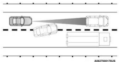
natural_image
Top-down diagram of four vehicles on a road with a dashed line indicating a lane or checkpoint (no text or symbols present)Lane Changing Example
Narrow Vehicles
Some narrow vehicles traveling near the outer edges of the lane or edging into the lane are not detected until they have moved fully into the lane. There may not be sufficient distance to the vehicle ahead.

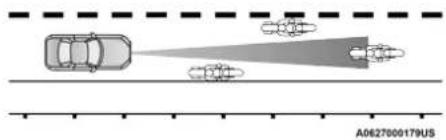
text_image
A0627000179USNarrow Vehicle Example
Stationary Objects And Vehicles
ACC does not react to stationary objects and stationary vehicles. For example, ACC will not react in situations where the vehicle you are following exits your lane and the vehicle ahead is stopped in your lane. Always be attentive and ready to apply the brakes if necessary.

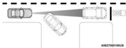
text_image
A0627000180USStationary Object And Stationary Vehicle Example
PARKSENSE FRONT AND REAR PARK ASSIST — IF EQUIPPED
The ParkSense Park Assist system provides visual and audible indications of the distance between the rear and/or front fascia/bumper and a detected obstacle when backing up or moving forward (e.g. during a parking maneuver).
For limitations of this system and recommendations, see ➤ page 125.
ParkSense will retain the system state (enabled or disabled) from the previous ignition cycle when the ignition is changed to the ON/RUN position.
ParkSense can be active only when the gear selector is in REVERSE or DRIVE. If ParkSense is enabled at one of these gear selector positions, the system will remain active until the vehicle speed is increased to approximately 7 mph (11 km/h) or above. The system will become active again if the vehicle speed is decreased to speeds less than approximately 6 mph (9 km/h).
PARKSENSE SENSORS
The four ParkSense sensors, located in the rear fascia/bumper, monitor the area behind the vehicle that is within the sensors' field of view. The sensors can detect obstacles from approximately 12 inches (30 cm) up to 79 inches (200 cm) from the rear fascia/bumper. These distances depend on the location, type, and orientation of the obstacle in the horizontal direction.
The six ParkSense sensors, located in the front fascia/bumper, monitor the area in front of the vehicle that is within the sensors' field of view. The sensors can detect obstacles from approximately 12 inches (30 cm) up to 47 inches (120 cm) from the front fascia/bumper. These distances depend on the location, type, and orientation of the obstacle in the horizontal direction.
PARKSENSE DISPLAY
The warning display will turn on indicating the system status when the vehicle is in REVERSE, or when the vehicle is in DRIVE and an obstacle has been detected.
The system will indicate a detected obstacle by showing a single arc in one or more regions based on the obstacle's distance and location relative to the vehicle.
If an obstacle is detected in the center rear region, the display will show a single solid arc in the center rear region and will produce a one-half second tone. As the vehicle moves closer to the obstacle, the display will show the single arc moving closer to the vehicle and the tone will change from slow, to fast, to continuous.
If an obstacle is detected in the left and/or right rear region, the display will show a single flashing arc in the left and/or right rear region and will produce a fast sound tone. As the vehicle moves closer to the obstacle, the display will show the single arc moving closer to the vehicle and the tone will change from fast to continuous.
If an obstacle is detected in the center front region, the display will show a single arc in the center front region. As the vehicle moves closer to the obstacle, the display will show the single arc moving closer to the vehicle. A fast sound tone will be produced when reaching the second flashing arc and will change to a continuous tone when the first flashing arc appears.
If an obstacle is detected in the left and/or right front region, the display will show a single flashing arc in the left and/or right front region and will produce a fast tone. As the vehicle moves closer to the obstacle, the display will show the single arc moving closer to the vehicle and the tone will change from fast to continuous.
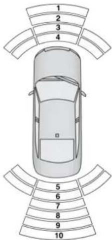
text_image
1 2 3 4 5 6 7 8 9 10A0629000265US
Front/Rear ParkSense Arcs
1 — No Tone/Solid Arc 6 — Fast Tone/Flashing Arc
2 — No Tone/Flashing Arc 7 — Fast Tone/Flashing Arc
3 — Fast Tone/Flashing Arc 8 — Slow Tone/Solid Arc
4 — Continuous Tone/Flashing Arc 9 — Slow Tone/Solid Arc
5 — Continuous Tone/Flashing Arc 10 — Single 1/2 Second Tone/Solid Arc
The vehicle is close to the obstacle when the instrument cluster display shows one flashing arc and sounds a continuous tone. The following charts show the warning alert operation when the system is detecting an obstacle:
| WARNING ALERTS FOR REAR | |||||||
| Rear Distance (inches/cm) | Greater than 79 inches (200 cm) | 79-59 inches (200-150 cm) | 59-47 inches (150-120 cm) | 47-39 inches (120-100 cm) | 39-25 inches (100-65 cm) | 25-12 inches (65-30 cm) | Less than 12 inches (30 cm) |
| Arcs — Left None | None None None None | None 6th Flashing | 5th Flashing | ||||
| Arcs — Center None | 10th Solid 9th | Solid 8th Solid 7th | Flashing 6th Flashing | 5th Flashing | |||
| Arcs — Right None | None None None | None 6th Flashing | 5th Flashing | ||||
| Audible Alert Chime | None | Single 1/2-Second Tone (for rear center only) | Slow (for rear center only) | Slow (for rear center only) | Fast (for rear center only) | Fast Continuous | |
| Radio Volume Reduced | No Yes Yes | Yes Yes Yes Yes | |||||
| WARNING ALERTS FOR FRONT | |||||
| Front Distance (inches/cm) | Greater than 47 inches (120 cm) | 47-39 inches (120-100 cm) | 39-25 inches (100-65 cm) | 25-12 inches (65-30 cm) | Less than 12 inches (30 cm) |
| Arcs – Left None | None None 3rd Flashing | 4th Flashing | |||
| Arcs – Center None | 1st Solid 2nd Flashing | 3rd Flashing 4th Flashing | |||
| Arcs – Right None | None None 3rd Flashing | 4th Flashing | |||
| Audible Alert Chime | None None None | Fast | Continuous | ||
| Radio Volume Reduced | No | No | No | Yes | Yes |
NOTE:
ParkSense will reduce the volume of the radio, if on, when the system is sounding an audio tone.
Front Park Assist Audible Alerts
ParkSense will turn off the Front Park Assist audible alert (chime) after approximately three seconds when an obstacle has been detected, the vehicle is stationary, and brake pedal is applied.
Adjustable Chime Volume Settings
Front and Rear chime volume settings can be selected in the Uconnect system ↩ page 144.
The chime volume settings include low, medium, and high.
ParkSense will retain its last known configuration state through ignition cycles.
PARKSENSE WARNING DISPLAY
The ParkSense Warning screen will only be displayed if Sound and Display is selected from within the Uconnect system ↩ page 144.
The ParkSense Warning screen is located within the instrument cluster display ➕ page 75. It provides visual warnings to indicate the distance between the rear fascia/bumper and/or front fascia/bumper and the detected obstacle.
ENABLING AND DISABLING PARKSENSE

ParkSense can be enabled and disabled with the ParkSense switch.
When the ParkSense switch is pushed
to disable the system, the instrument cluster will display the "ParkSense Off" message for approximately five seconds. When the gear selector is moved to REVERSE and the system is disabled, the instrument cluster will display the "ParkSense Off" message for as long as the vehicle is in REVERSE.
The ParkSense switch LED will be on when ParkSense is disabled or requires service. The ParkSense switch LED will be off when the system is enabled. If the ParkSense switch is pushed and the system requires service, the ParkSense switch LED will blink momentarily and then the LED will be on.
SERVICE THE PARKSENSE PARK ASSIST SYSTEM
During vehicle start up, when the ParkSense System has detected a faulted condition, the instrument cluster will actuate a single chime, once per ignition cycle, and it will display the "PARKSENSE UNAVAILABLE WIPE REAR SENSORS", "PARKSENSE UNAVAILABLE WIPE
FRONT SENSORS", or the "PARKSENSE UNAVAILABLE SERVICE REQUIRED" message for five seconds. When the gear selector is moved to REVERSE and the system has detected a faulted condition, the instrument cluster display will display a "PARKSENSE UNAVAILABLE WIPE REAR SENSORS", "PARKSENSE UNAVAILABLE WIPE FRONT SENSORS" or "PARKSENSE UNAVAILABLE SERVICE REQUIRED" pop up message for five seconds. After five seconds, a vehicle graphic will be displayed with "UNAVAILABLE" at either the front or rear sensor location depending on where the fault is detected. The system will continue to provide arc alerts for the side that is functioning properly. These arc alerts will interrupt the "PARKSENSE UNAVAILABLE WIPE REAR SENSORS", "PARKSENSE UNAVAILABLE WIPE FRONT SENSORS", or "PARKSENSE UNAVAILABLE SERVICE REQUIRED" messages if an object is detected within the five second pop-up duration. The vehicle graphic will remain displayed for as long as the vehicle is in REVERSE.
If "PARKSENSE UNAVAILABLE WIPE REAR SENSORS" or "PARKSENSE UNAVAILABLE WIPE FRONT SENSORS" appears in the instrument cluster display make sure the outer surface and the underside of the rear fascia/bumper and/or front fascia/bumper is clean and clear of snow, ice, mud, dirt or other obstruction and then cycle the ignition. If the message continues to appear see an authorized dealer.
If the "PARKSENSE UNAVAILABLE SERVICE REQUIRED" message appears in the instrument cluster display, see an authorized dealer.
CLEANING THE PARKSENSE SYSTEM
Clean the ParkSense sensors with water, car wash soap and a soft cloth. Do not use rough or hard cloths. Do not scratch or poke the sensors. Otherwise, you could damage the sensors.
PARKSENSE SYSTEM USAGE PRECAUTIONS
NOTE:
- Ensure that the front and rear bumpers are free of snow, ice, mud, dirt and debris to keep the ParkSense system operating properly.
- Jackhammers, large trucks, and other vibrations could affect the performance of ParkSense.
126 STARTING AND OPERATING
- When you turn ParkSense off, the instrument cluster will display "PARKSENSE OFF." Once you turn ParkSense off, it remains off until you turn it on again, even if you cycle the ignition.
- When you move the gear selector to the REVERSE position and ParkSense is turned off, the instrument cluster will display "PARK-SENSE OFF" for as long as the vehicle is in REVERSE.
- ParkSense, when on, will reduce the volume of the radio when it is sounding a tone.
- Clean the ParkSense sensors regularly, taking care not to scratch or damage them. The sensors must not be covered with ice, snow, slush, mud, dirt or debris. Failure to do so can result in the system not working properly. The ParkSense system might not detect an obstacle behind or in front of the fascia/bumper, or it could provide a false indication that an obstacle is behind or in front of the fascia/bumper.
- Use the ParkSense switch to turn the ParkSense system off if objects such as bicycle carriers, trailer hitches, etc. are placed within 12 inches (30 cm) from the rear fascia/bumper. Failure to do so can result in the system misinterpreting a close object as a sensor problem, causing the "PARKSENSE UNAVAILABLE SERVICE REQUIRED" message to be displayed in the instrument cluster.
WARNING!
- Drivers must be careful when backing up even when using ParkSense. Always check carefully behind your vehicle, look behind you, and be sure to check for pedestrians, animals, other vehicles, obstructions, and blind spots before backing up. You are responsible for safety and must continue to pay attention to your surroundings. Failure to do so can result in serious injury or death.
(Continued)
WARNING! (Continued)
- Before using ParkSense, it is strongly recommended that the ball mount and hitch ball assembly is disconnected from the vehicle when the vehicle is not used for towing. Failure to do so can result in injury or damage to vehicles or obstacles because the hitch ball will be much closer to the obstacle than the rear fascia/bumper when the loudspeaker sounds the continuous tone. Also, the sensors could detect the ball mount and hitch ball assembly, depending on its size and shape, giving a false indication that an obstacle is behind the vehicle.
CAUTION!
- ParkSense is only a parking aid and it is unable to recognize every obstacle, including small obstacles. Parking curbs might be temporarily detected or not detected at all. Obstacles located above or below the sensors will not be detected when they are in close proximity.
- The vehicle must be driven slowly when using ParkSense in order to be able to stop in time when an obstacle is detected. It is recommended that the driver looks over his/her shoulder when using ParkSense.
LANESENSE — IF EQUIPPED
LANESENSE OPERATION
The LaneSense system is operational at speeds above 37 mph (60 km/h) and below 112 mph (180 km/h). The LaneSense system uses a forward looking camera to detect lane markings and measure vehicle position within the lane boundaries.
When both lane markings are detected and the driver unintentionally drifts out of the lane (no turn signal applied), the LaneSense system provides a haptic warning in the form of torque applied to the steering wheel to prompt the driver to remain within the lane boundaries. If the driver unintentionally drifts out of the lane, the LaneSense system provides a visual warning through the instrument cluster display to prompt the driver to remain within the lane boundaries. The driver may manually override the haptic warning by applying torque into the steering wheel at any time.
When only a single lane marking is detected and the driver unintentionally drifts across the lane marking (no turn signal applied), the LaneSense system provides visual warnings through the instrument cluster display to prompt the driver to remain within the lane. When only a single lane marking is detected, a haptic (torque) warning will not be provided.
NOTE:
When operating conditions have been met, the LaneSense system will monitor if the driver's hands are on the steering wheel and provide an audible warning to the driver if removed. The system will cancel if the driver does not return their hands to the wheel.
TURNING LANESENSE ON OR OFF

The LaneSense button is located on the center stack below the Uconnect display.
To turn the LaneSense system on, push the LaneSense button (LED turns off). A "LaneSense On" message is shown in the instrument cluster display.
To turn the LaneSense system off, push the LaneSense button once (LED turns on). A "LaneSense Off" message is shown in the instrument cluster display.
NOTE:
The LaneSense system will retain the last system state, on or off, from the last ignition cycle when the ignition is changed to the ON/RUN position.
LANESENSE WARNING MESSAGE
The LaneSense system will indicate the current lane drift condition through the instrument cluster display.
Premium Instrument Cluster Display
When the LaneSense system is on, the lane lines are gray when both of the lane boundaries have not been detected and the LaneSense telltale is solid white.

natural_image
Top-down view of a car with two vertical arrows pointing downward, no text or symbols presentSystem On (Gray Lines/White Telltale)
Left Lane Departure — Only Left Lane Detected
- When the LaneSense system is on, the LaneSense telltale is solid white when only the left lane marking has been detected and the system is ready to provide visual warnings in the instrument cluster display if an unintentional lane departure occurs.
- When the LaneSense system senses the lane has been approached and is in a lane departure situation, the left thick lane line flashes yellow (on/off), the left thin line remains solid yellow and the LaneSense telltale changes from solid white to flashing yellow.
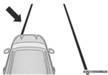
natural_image
Diagram of a car with two vertical lines and an arrow pointing downward (no text or symbols)Lane Approached With Flashing Yellow Line/Flashing Yellow Telltale
NOTE:
The LaneSense system operates with similar behavior for a right lane departure when only the right lane marking has been detected.
Left Lane Departure — Both Lanes Detected
- When the LaneSense system is on, the lane lines turn from gray to white to indicate that both of the lane markings have been detected. The LaneSense telltale is solid green when both lane markings have been detected and the system is “armed” to provide visual warnings in the instrument cluster display and a torque warning in the steering wheel if an unintentional lane departure occurs.
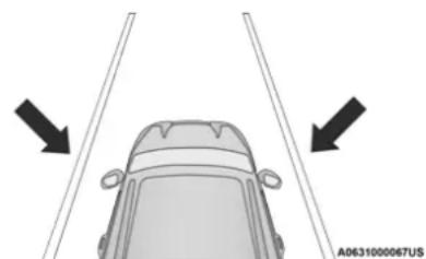
natural_image
Top-down view of a car viewed from above with two vertical guide rails and directional arrows indicating motion (no text or symbols)Lanes Sensed (White Lines/Green Telltale)
- When the LaneSense system senses a lane drift situation, the left thick lane line and left thin line turn solid yellow. The LaneSense tell-tale changes from solid green to solid yellow. At this time torque is applied to the steering wheel in the opposite direction of the lane boundary.
For example, if approaching the left side of the lane the steering wheel will turn to the right.
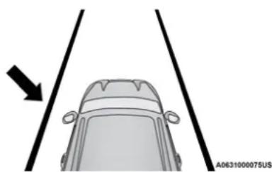
natural_image
Top-down view of a car viewed from above with two vertical lines and an arrow pointing downward (no text or symbols)Lane Drift With Solid Yellow Line/Solid Yellow Telltale
- When the LaneSense system senses the lane has been approached and is in a lane departure situation, the left thick lane line flashes yellow (on/off) and the left thin line remains solid yellow. The LaneSense telltale changes from solid yellow to flashing yellow. At this
time torque is applied to the steering wheel in the opposite direction of the lane boundary.
For example, if approaching the left side of the lane the steering wheel will turn to the right.
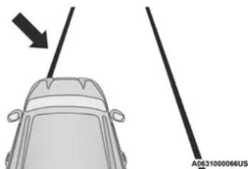
natural_image
Top-down diagram of a car showing a vertical pole with an arrow pointing downward (no text or symbols)Lane Approached With Flashing Yellow Line/Flashing Yellow Telltale
NOTE:
The LaneSense system operates with similar behavior for a right lane departure.
CHANGING LANESENSE STATUS
The LaneSense system has settings to adjust the intensity of the torque warning and the warning zone sensitivity (early/med/late) that you can configure through the Uconnect system → page 144.
NOTE:
- When enabled, the system operates above 37 mph (60 km/h) and below 112 mph (180 km/h).
- The warnings are disabled with the use of the turn signal.
- The system will not apply torque to the steering wheel whenever a safety system engages (Anti-Lock Brakes, Traction Control System, Electronic Stability Control, Forward Collision Warning, etc.).
PARKVIEW REAR BACK UP CAMERA
The ParkView Rear Back Up Camera allows you to see an on-screen image of the rear surroundings of your vehicle whenever the gear selector is put into REVERSE. The image will be displayed on the radio display screen along with a caution note to "Check Entire Surroundings" across the top of the screen. After five seconds this note will disappear. The ParkView camera is located on the rear of the vehicle above the rear license plate.
Manual Activation Of The Rear View Camera
- Press the "Controls" button located on the bottom of the Uconnect display.
- Press the "Backup Camera" button to turn the Rear View Camera system on.
NOTE:
The ParkView Rear Back Up Camera has programmable modes of operation that may be selected through the Uconnect system page 144.
If your vehicle is equipped with the Camera Delay feature and it is turned on, the rear camera image will be displayed for up to 10 seconds when the vehicle is shifted out of REVERSE. However, this feature is canceled if the forward vehicle speed exceeds 8 mph (13 km/h), the transmission is shifted into PARK, the vehicle's ignition is placed in the OFF position, or the user presses the image defeat "X" button.
When the vehicle is shifted out of REVERSE (with Camera Delay turned off), the rear camera mode is exited and the last touchscreen appears again.
When manually activated, a counter will be initiated after the vehicle speed is above 8 mph (13 km/h). The rear view camera image will turn off when this counter reaches 10 seconds. The counter will be reset when the vehicle speed is 8 mph (13 km/h) or below. If the vehicle speed remains below 8 mph (13 km/h), the rear view camera image will continue to be displayed until the transmission is shifted into PARK, the vehicle's ignition is placed in the OFF position, or the image defeat "X" button is pressed.
When enabled, active guidelines are overlaid on the image to illustrate the width of the vehicle and its projected backup path based on the steering wheel position. Different colored zones indicate the distance to the rear of the vehicle. The following table shows the approximate distances for each zone:
| Zone | Distance To The Rear Of The Vehicle |
| Red 0 - 1 ft (0 - 30 cm) | |
| Yellow | 1 ft - 6.5 ft(30 cm - 2 m) |
| Green | 6.5 ft or greater(2 m or greater) |
WARNING!
Drivers must be careful when backing up even when using the ParkView Rear Back Up Camera. Always check carefully behind your vehicle, and be sure to check for pedestrians, animals, other vehicles, obstructions, or blind spots before backing up. You are responsible for the safety of your surroundings and must continue to pay attention while backing up. Failure to do so can result in serious injury or death.
CAUTION!
- To avoid vehicle damage, ParkView should only be used as a parking aid. The ParkView camera is unable to view every obstacle or object in your drive path.
- To avoid vehicle damage, the vehicle must be driven slowly when using ParkView to be able to stop in time when an obstacle is seen. It is recommended that the driver look frequently over his/her shoulder when using ParkView.
- It is recommended that the driver look frequently over his/her shoulder when backing up, especially in sunny weather conditions, since there may be a glare from the sun at certain angles that can make the image on the touchscreen difficult to see.
NOTE:
If snow, ice, mud, or any foreign substance builds up on the camera lens, clean the lens, rinse with water, and dry with a soft cloth. Do not cover the lens.
REFUELING THE VEHICLE
- Push the fuel filler door release switch (located in the driver's door map pocket).
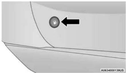
natural_image
Close-up of a car's side panel with a circular button and an arrow pointing to it (no text or symbols visible)Fuel Filler Door Release Switch
- Open the fuel filler door.
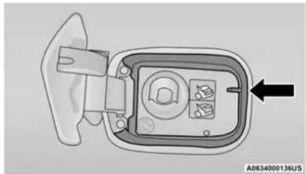
natural_image
Diagram of a device component with a black arrow pointing to it, showing internal components without any text or symbols.Fuel Filler Location
NOTE:
In certain cold conditions, ice may prevent the fuel door from opening. If this occurs, lightly push on the fuel door to break the ice buildup and re-release the fuel door using the inside release button. Do not pry on the door.
- There is no fuel filler cap. Two flapper doors inside the pipe seal the system.
- Insert the fuel nozzle fully into the filler pipe – the nozzle opens and holds the flapper doors while refueling.
- Fill the vehicle with fuel - when the fuel nozzle "clicks" or shuts off the fuel tank is full.
- Maintain nozzle in filler for five seconds to allow nozzle to drain.
- Remove the fuel nozzle and close the fuel door.
NOTE:
A funnel is provided (located in the trunk in the spare tire area) to open the flapper doors to allow for emergency refueling with a gas can.
WARNING!
- Never have any smoking materials lit in or near the vehicle when the fuel door is open or the tank is being filled.
- Never add fuel when the engine is running. This is in violation of most state and federal fire regulations and may cause the "Malfunction Indicator Light" to turn on.
- A fire may result if fuel is pumped into a portable container that is inside of a vehicle. You could be burned. Always place fuel containers on the ground while filling.
CAUTION!
To avoid fuel spillage and overfilling, do not "top off" the fuel tank after filling.
EMERGENCY FUEL FILLER DOOR RELEASE
If you are unable to open the fuel filler door, use the fuel filler door emergency release located in the trunk.
Follow the steps below to open the fuel door in case of an emergency:
- Open the trunk.
- Remove the access cover (located on the left side inner trim panel).
Access Cover
A0634000137US
- Pull the release cable.
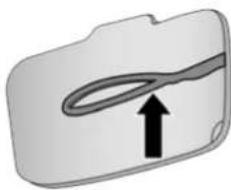
natural_image
Simple 3D icon of a folder with a curved line and an upward arrow, no text or symbols present.A0634000138US
Release Cable
VEHICLE LOADING
The load carrying capacity of your vehicle is shown on the "Vehicle Certification Label". This information should be used for passenger and luggage loading as indicated.
Do not exceed the specified Gross Vehicle Weight Rating (GVWR) or the Gross Axle Weight Rating (GAWR).
VEHICLE CERTIFICATION LABEL
Your vehicle has a Vehicle Certification Label affixed to the drivers side B-pillar or the rear of the driver's door.
The label contains the following information:
• Name of manufacturer
● Month and year of manufacture
● Gross Vehicle Weight Rating (GVWR)
● Gross Axle Weight Rating (GAWR) front
● Gross Axle Weight Rating (GAWR) rear
● Vehicle Identification Number (VIN)
- Type of vehicle
● Month, Day, and Hour of manufacture (MDH)
The bar code allows a computer scanner to read the VIN.
GROSS VEHICLE WEIGHT RATING (GVWR)
The GVWR is the total allowable weight of your vehicle. This includes driver, passengers, and cargo. The total load must be limited so that you do not exceed the GVWR.
GROSS AXLE WEIGHT RATING (GAWR)
The GAWR is the maximum capacity of the front and rear axles. Distribute the load over the front and rear axles evenly. Make sure that you do not exceed either front or rear GAWR.
WARNING!
Because the front wheels steer the vehicle, it is important that you do not exceed the maximum front or rear GAWR. A dangerous driving condition can result if either rating is exceeded. You could lose control of the vehicle and have a collision.
OVERLOADING
The load carrying components (axle, springs, tires, wheels, etc.) of your vehicle will provide satisfactory service as long as you do not exceed the GVWR and the front and rear GAWR.
The best way to figure out the total weight of your vehicle is to weigh it when it is fully loaded and ready for operation. Weigh it on a commercial scale to ensure that it is not over the GVWR.
Figure out the weight on the front and rear of the vehicle separately. It is important that you distribute the load evenly over the front and rear axles.
Overloading can cause potential safety hazards and shorten useful service life. Heavier axles or suspension components do not necessarily increase the vehicle's GVWR.
LOADING
To load your vehicle properly, first figure out its empty weight, axle-by-axle and side-by-side. Store heavier items down low and be sure you distribute their weight as evenly as possible. Stow all loose items securely before driving. If weighing the loaded vehicle shows that you have exceeded either GAWR, but the total load is within the specified GVWR, you must redistribute the weight. Improper weight distribution can have an adverse effect on the way your vehicle steers and handles and the way the brakes operate.
NOTE:
- Refer to the "Vehicle Certification Label" affixed to the rear of the driver's door for your vehicle's GVWR and GAWRs ➤ page 132.
- Refer to the "Tire Placard" for your vehicle's proper tire pressure.
TRAILER TOWING
In this section you will find safety tips and information on limits to the type of towing you can reasonably do with your vehicle. Before towing a trailer, carefully review this information to tow your load as efficiently and safely as possible.
To maintain the New Vehicle Limited Warranty coverage, follow the requirements and recommendations in this manual concerning vehicles used for trailer towing.
COMMON TOWING DEFINITIONS
The following trailer towing related definitions will assist you in understanding the following information:
Gross Vehicle Weight Rating (GVWR)
The GVWR is the total allowable weight of your vehicle. This includes driver, passengers, cargo and tongue weight. The total load must be limited so that you do not exceed the GVWR page 133.
Gross Trailer Weight (GTW)
The GTW is the weight of the trailer plus the weight of all cargo, consumables, and equipment (permanent or temporary) loaded in or on the trailer in its "loaded and ready for operation" condition.
The recommended way to measure GTW is to put your fully loaded trailer on a vehicle scale. The entire weight of the trailer must be supported by the scale.
Gross Combination Weight Rating (GCWR)
The GCWR is the total allowable weight of your vehicle and trailer when weighed in combination.
Gross Axle Weight Rating (GAWR)
The GAWR is the maximum capacity of the front and rear axles. Distribute the load over the front and rear axles evenly. Make sure that you do not exceed either front or rear GAWR page 133.
WARNING!
It is important that you do not exceed the maximum front or rear GAWR. A dangerous driving condition can result if either rating is exceeded. You could lose control of the vehicle and have a collision.
Tongue Weight (TW)
The tongue weight is the downward force exerted on the hitch ball by the trailer. You must consider this as part of the load on your vehicle.
Trailer Frontal Area
The frontal area is the maximum height multiplied by the maximum width of the front of a trailer.
Trailer Sway Control
The Trailer Sway Control (TSC) can be a mechanical telescoping link that can be installed between the hitch receiver and the trailer tongue that typically provides adjustable friction associated with the telescoping motion to dampen any unwanted trailer swaying motions while traveling.
If equipped, the electronic TSC recognizes a swaying trailer and automatically applies individual wheel brakes and/or reduces engine power to attempt to eliminate the trailer sway.
Weight-Carrying Hitch
A weight-carrying hitch supports the trailer tongue weight, just as if it were luggage located at a hitch ball or some other connecting point of the vehicle. These kinds of hitches are the most popular on the market today and they are commonly used to tow small and medium sized trailers.
Weight-Distributing Hitch
A weight-distributing system works by applying leverage through spring (load) bars. They are typically used for heavier loads to distribute trailer tongue weight to the tow vehicle's front axle and the trailer axle(s). When used in accordance with the manufacturer's directions, it provides for a more level ride, offering more consistent steering and brake control thereby enhancing towing safety. The addition of a friction/hydraulic sway control also dampens sway caused by traffic and crosswinds and contributes positively to tow vehicle and trailer stability. Trailer sway control and a weight distributing (load equalizing) hitch are recommended for heavier Tongue Weights (TW) and may be required depending on vehicle and trailer configuration/loading to comply with Gross Axle Weight Rating (GAWR) requirements.
WARNING!
- An improperly adjusted Weight Distributing Hitch system may reduce handling, stability, braking performance, and could result in a collision.
- Weight Distributing Systems may not be compatible with Surge Brake Couplers. Consult with your hitch and trailer manufacturer or a reputable Recreational Vehicle dealer for additional information.
TRAILER HITCH CLASSIFICATION
The following chart provides the industry standard for the maximum trailer weight a given trailer hitch class can tow and should be used to assist you in selecting the correct trailer hitch for your intended towing condition.
| Trailer Hitch Classification Definitions | |
| Class Max. Trailer Hitch Industry Standards | |
| Class I - Light Duty 2,000 lbs (907 kg) | |
| Class II - Medium Duty 3,500 lbs (1,587 kg) | |
| Class III - Heavy Duty 6,000 lbs (2,722 kg) | |
| Class IV - Extra Heavy Duty 10,000 lbs (4,535 kg) | |
| Refer to the “Trailer Towing Weights (Maximum Trailer Weight Ratings)” chart for the Maximum Gross Trailer Weight (GTW) towable for your given drivetrain. | |
| All trailer hitches should be professionally installed on your vehicle. | |
| Engine/Transmission Frontal Area Max. GTW (Gross Trailer Weight) Max. Tongue Weight (See Note) | |||
| 3.6L Automatic | 22 sq ft (2.04 sq m) | 1,000 lbs (454 kg) | 100 lbs (45 kg) |
| 5.7L Automatic | 32 sq ft (2.97 sq m) | 1,000 lbs (454 kg) | 100 lbs (45 kg) |
| Refer to local laws for maximum trailer towing speeds. | |||
NOTE:
The trailer tongue weight must be considered as part of the combined weight of occupants and cargo, and it should never exceed the weight referenced on the "Tire and Loading Information" placard → page 263.
TRAILER AND TONGUE WEIGHT
Never exceed the maximum tongue weight stamped on your bumper or trailer hitch.
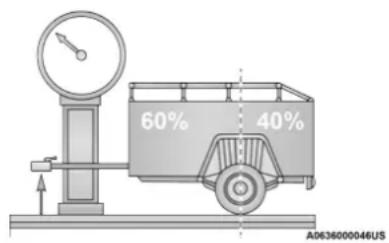
text_image
60% 40% A0636000046USWeight Distribution
Consider the following items when computing the weight on the rear axle of the vehicle:
- The tongue weight of the trailer.
- The weight of any other type of cargo or equipment put in or on your vehicle.
- The weight of the driver and all passengers.
NOTE:
Remember that everything put into or on the trailer adds to the load on your vehicle. Also, additional factory-installed options or dealer-installed options must be considered as part of the total load on your vehicle. Refer to the "Tire And Loading Information" placard for the maximum combined weight of occupants and cargo for your vehicle.
TOWING REQUIREMENTS
To promote proper break-in of your new vehicle drivetrain components, the following guidelines are recommended.
WARNING!
- Make certain that the load is secured in the trailer and will not shift during travel. When trailering cargo that is not fully secured, dynamic load shifts can occur that may be difficult for the driver to control. You could lose control of your vehicle and have a collision.
- When hauling cargo or towing a trailer, do not overload your vehicle or trailer. Overloading can cause a loss of control, poor performance or damage to brakes, axle, engine, transmission, steering, suspension, chassis structure or tires.
(Continued)
WARNING! (Continued)
- Safety chains must always be used between your vehicle and trailer. Always connect the chains to the hook retainers of the vehicle hitch. Cross the chains under the trailer tongue and allow enough slack for turning corners.
- Vehicles with trailers should not be parked on a grade. When parking, apply the parking brake on the tow vehicle. Put the tow vehicle transmission in PARK. Always, block or "chock" the trailer wheels.
• GCWR must not be exceeded. - Total weight must be distributed between the tow vehicle and the trailer such that the following four ratings are not exceeded:
- Max loading as defined on the "Tire and Loading Information" placard.
• GTW - GAWR
- Tongue weight rating for the trailer hitch utilized.
Perform the maintenance listed in the "Scheduled Servicing" page 228. When towing a trailer, never exceed the GAWR or GCWR ratings.
CAUTION!
- Do not tow a trailer at all during the first 500 miles (805 km) the new vehicle is driven. The engine, axle or other parts could be damaged.
- Then, during the first 500 miles (805 km) that a trailer is towed, do not drive over 50 mph (80 km/h) and do not make starts at full throttle. This helps the engine and other parts of the vehicle wear in at the heavier loads.
Towing Requirements — Tires
- Do not attempt to tow a trailer while using a compact spare tire.
- Do not drive more than 50 mph (80 km/h) when towing while using a full size spare tire.
-
Proper tire inflation pressures are essential to the safe and satisfactory operation of your vehicle.
-
Check the trailer tires for proper tire inflation pressures before trailer usage.
- Check for signs of tire wear or visible tire damage before towing a trailer.
- For the proper tire replacement procedures. Replacing tires with a higher load carrying capacity will not increase the vehicle's GVWR and GAWR limits.
- For further information ➤ page 263.
Towing Requirements — Trailer Brakes
- Do not interconnect the hydraulic brake system or vacuum system of your vehicle with that of the trailer. This could cause inadequate braking and possible personal injury.
- An electronically actuated trailer brake controller is required when towing a trailer with electronically actuated brakes. When towing a trailer equipped with a hydraulic surge actuated brake system, an electronic brake controller is not required.
- Trailer brakes are recommended for trailers over 1,000 lbs (453 kg) and required for trailers in excess of 2,000 lbs (907 kg).
WARNING!
- Do not connect trailer brakes to your vehicle's hydraulic brake lines. It can overload your brake system and cause it to fail. You might not have brakes when you need them and could have an accident.
- Towing any trailer will increase your stopping distance. When towing, you should allow for additional space between your vehicle and the vehicle in front of you. Failure to do so could result in an accident
CAUTION!
If the trailer weighs more than 1,000 lbs (453 kg) loaded, it should have its own brakes and they should be of adequate capacity. Failure to do this could lead to accelerated brake lining wear, higher brake pedal effort, and longer stopping distances.
Towing Requirements — Trailer Lights And Wiring
Whenever you pull a trailer, regardless of the trailer size, stoplights and turn signals on the trailer are required for motoring safety.
The Trailer Tow Package may include a four- and seven-pin wiring harness. Use a factory approved trailer harness and connector.
NOTE:
Do not cut or splice wiring into the vehicle's wiring harness.
The electrical connections are all complete to the vehicle but you must mate the harness to a trailer connector. Refer to the following illustrations.
NOTE:
- Disconnect trailer wiring connector from the vehicle before launching a boat (or any other device plugged into vehicle's electrical connect) into water.
- Be sure to reconnect after clear from water area.
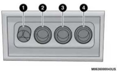
text_image
1 2 3 4 M0636000043USFour-Pin Connector
1 - Ground
2 - Park
3 - Left Stop/Turn
4 - Right Stop/Turn
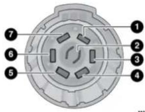
text_image
1 2 3 4 5 6 7Seven-Pin Connector
1 - Battery
2 - Backup Lamps
3 - Right Stop/Turn
4 - Electric Brakes
5 - Ground
6 - Left Stop/Turn
7 – Running Lamps
TOWING TIPS
Before setting out on a trip, practice turning, stopping, and backing up the trailer in an area located away from heavy traffic.
Automatic Transmission
Select the DRIVE range when towing. The transmission controls include a drive strategy to avoid frequent shifting when towing. However, if frequent shifting does occur while in DRIVE, you can use the AutoStick shift control (if equipped) to manually select a lower gear.
NOTE:
Using a lower gear while operating the vehicle under heavy loading conditions will improve performance and extend transmission life by reducing excessive shifting and heat buildup. This action will also provide better engine braking.
Cruise Control — If Equipped
- Do not use on hilly terrain or with heavy loads.
- When using the Cruise Control, if you experience speed drops greater than 10 mph (16 km/h), disengage until you can get back to cruising speed.
- Use Cruise Control in flat terrain and with light loads to maximize fuel efficiency.
AutoStick — If Equipped
- When using the AutoStick shift control, select the highest gear that allows for adequate performance and avoids frequent downshifts. For example, choose "5" if the desired speed can be maintained. Choose "4" or "3" if needed to maintain the desired speed.
- To prevent excess heat generation, avoid continuous driving at high RPM. Reduce vehicle speed as necessary to avoid extended driving at high RPM. Return to a higher gear or vehicle speed when grade and road conditions allow.
RECREATIONAL TOWING (BEHIND MOTORHOME)
Recreational towing (with all four wheels on the ground, or using a tow dolly) is NOT ALLOWED. The only acceptable method for towing this vehicle (behind another vehicle) is on a vehicle trailer with all four wheels OFF the ground.
CAUTION!
Towing this vehicle in violation of the above requirements can cause severe transmission and/or transfer case damage. Damage from improper towing is not covered under the New Vehicle Limited Warranty.
DRIVING TIPS
DRIVING ON SLIPPERY SURFACES
Information in this section will aid in safe controlled launches in adverse conditions.
Acceleration
Rapid acceleration on snow covered, wet, or other slippery surfaces may cause the driving wheels to pull erratically to the right or left. This phenomenon occurs when there is a difference in the surface traction under the rear (driving) wheels.
WARNING!
Rapid acceleration on slippery surfaces is dangerous. Unequal traction can cause sudden pulling of the front wheels. You could lose control of the vehicle and possibly have a collision. Accelerate slowly and carefully whenever there is likely to be poor traction (ice, snow, wet, mud, loose sand, etc.).
Traction
When driving on wet or slushy roads, it is possible for a wedge of water to build up between the tire and road surface. This is known as hydroplaning and may cause partial or complete loss of vehicle control and stopping ability. To reduce this possibility, the following precautions should be observed:
- Slow down during rainstorms or when the roads are slushy.
- Slow down if the road has standing water or puddles.
- Replace tires when tread wear indicators first become visible.
- Keep tires properly inflated.
- Maintain sufficient distance between your vehicle and the vehicle in front of you to avoid a collision in a sudden stop.
Your vehicle may be equipped with a Limited Slip Differential (LSD) that reduces, but does not eliminate, the amount of wheel slip across a given axle for improved handling.
DRIVING THROUGH WATER
Driving through water more than a few inches/centimeters deep will require extra caution to ensure safety and prevent damage to your vehicle.
Flowing/Rising Water
WARNING!
Do not drive on or across a road or path where water is flowing and/or rising (as in storm run-off). Flowing water can wear away the road or path's surface and cause your vehicle to sink into deeper water. Furthermore, flowing and/or rising water can carry your vehicle away swiftly. Failure to follow this warning may result in injuries that are serious or fatal to you, your passengers, and others around you.
Shallow Standing Water
Although your vehicle is capable of driving through shallow standing water, consider the following Warnings and Cautions before doing so.
WARNING!
- Driving through standing water limits your vehicle's traction capabilities. Do not exceed 5 mph (8 km/h) when driving through standing water.
- Driving through standing water limits your vehicle's braking capabilities, which increases stopping distances. Therefore, after driving through standing water, drive slowly and lightly press on the brake pedal several times to dry the brakes.
- Failure to follow these warnings may result in injuries that are serious or fatal to you, your passengers, and others around you.
CAUTION!
- Always check the depth of the standing water before driving through it. Never drive through standing water that is deeper than the bottom of the tire rims mounted on the vehicle.
- Determine the condition of the road or the path that is under water and if there are any obstacles in the way before driving through the standing water.
- Do not exceed 5 mph (8 km/h) when driving through standing water. This will minimize wave effects.
(Continued)
CAUTION! (Continued)
- Driving through standing water may cause damage to your vehicle's drivetrain components. Always inspect your vehicle's fluids (i.e., engine oil, transmission, axle, etc.) for signs of contamination (i.e., fluid that is milky or foamy in appearance) after driving through standing water. Do not continue to operate the vehicle if any fluid appears contaminated, as this may result in further damage. Such damage is not covered by the New Vehicle Limited Warranty.
- Getting water inside your vehicle's engine can cause it to lock up and stall out, and cause serious internal damage to the engine. Such damage is not covered by the New Vehicle Limited Warranty.
MULTIMEDIA
UCONNECT SYSTEMS
For detailed information about your Uconnect system, refer to your Uconnect Owner's Manual Supplement.
NOTE:
Uconnect screen images are for illustration purposes only and may not reflect exact software for your vehicle.
CYBERSECURITY
Your vehicle may be a connected vehicle and may be equipped with both wired and wireless networks. These networks allow your vehicle to send and receive information. This information allows systems and features in your vehicle to function properly.
Your vehicle may be equipped with certain security features to reduce the risk of unauthorized and unlawful access to vehicle systems and wireless communications. Vehicle software technology continues to evolve over time and FCA US LLC, working with its suppliers, evaluates and takes appropriate steps as needed. Similar to a computer or other devices, your vehicle may require software updates to improve the usability and performance of your systems or to reduce the potential risk of unauthorized and unlawful access to your vehicle systems.
The risk of unauthorized and unlawful access to your vehicle systems may still exist, even if the most recent version of vehicle software (such as Uconnect software) is installed.
WARNING!
- It is not possible to know or to predict all of the possible outcomes if your vehicle's systems are breached. It may be possible that vehicle systems, including safety related systems, could be impaired or a loss of vehicle control could occur that may result in an accident involving serious injury or death.
- ONLY insert media (e.g., USB or CD) into your vehicle if it came from a trusted source. Media of unknown origin could possibly contain malicious software, and if installed in your vehicle, it may increase the possibility for vehicle systems to be breached.
(Continued)
WARNING! (Continued)
- As always, if you experience unusual vehicle behavior, take your vehicle to your nearest authorized dealer immediately.
NOTE:
- FCA US LLC or an authorized dealer may contact you directly regarding software updates.
- To help further improve vehicle security and minimize the potential risk of a security breach, vehicle owners should:
- FCA US LLC or an authorized dealer may contact you directly regarding software updates. - To help further improve vehicle security and minimize the potential risk of a security breach, vehicle owners should:
- Routinely check www.driveuconnect.com (US Residents) or www.driveuconnect.ca (Canadian Residents) to learn about available Uconnect software updates.
- Only connect and use trusted media devices (e.g. personal mobile phones, USBs, CDs).
- Routinely check www.driveuconnect.com (US Residents) or www.driveuconnect.ca (Canadian Residents) to learn about available Uconnect software updates. - Only connect and use trusted media devices (e.g. personal mobile phones, USBs, CDs).
144 MULTIMEDIA
Privacy of any wireless and wired communications cannot be assured. Third parties may unlawfully intercept information and private communications without your consent. For further information, refer to "Data Collection & Privacy" in your Uconnect Owner's Manual Supplement or "Onboard Diagnostic System (OBD II) Cybersecurity" ➞ page 91.
UCONNECT SETTINGS
The Uconnect system uses a combination of buttons on the touchscreen and buttons on the faceplate located on the center of the instrument panel. These buttons allow you to access and change the Customer Programmable Features. Many features can vary by vehicle.
Buttons on the faceplate are located below and/or beside the Uconnect system in the center of the instrument panel. In addition, there is a Scroll/Enter control knob located on the right side. Turn the control knob to scroll through menus and change settings. Push the center of the control knob one or more times to select or change a setting.
Your Uconnect system may also have Screen Off and Mute buttons on the faceplate.
Push the Screen Off button on the faceplate to turn off the Uconnect screen. Push the button again or tap the screen to turn the screen on.
Press the Back Arrow button to exit out of a Menu or certain option on the Uconnect system.
CUSTOMER PROGRAMMABLE FEATURES — U CONNECT 4C/4C NAV SETTINGS
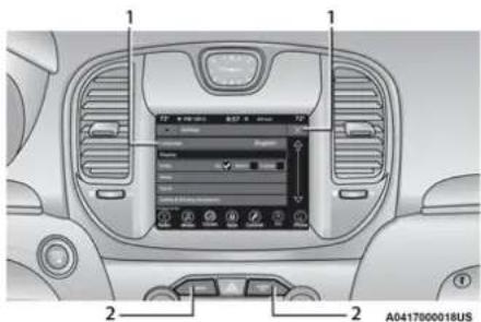
text_image
1 1 2 2 A0417800018USUconnect 4C/4C NAV With 8.4-inch Display Buttons On The Touchscreen And Buttons On The Faceplate
1 – Uconnect Buttons On The Touchscreen
2 — Uconnect Buttons On The Faceplate
Press the Apps 📣 button, then press the Settings button on the touchscreen to display the menu setting screen. In this menu, the Uconnect system allows you to access all of the available programmable features.
NOTE:
Depending on the vehicle's options, feature settings may vary.
When making a selection, press the button on the touchscreen to enter the desired menu. Once in the desired menu, press and release the preferred setting "option" until a check mark appears next to the setting, showing that setting has been selected. Once the setting is complete, press the X button on the touchscreen to close out of the settings screen. Pressing the Up or Down Arrow button on the right side of the screen will allow you to toggle up or down through the available settings.
The following tables list the settings that may be found within the Uconnect 4C/4C NAV radio, along with the selectable options pertaining to each setting.
Language
When the Language button is pressed on the touchscreen, the system displays the different language options. Once an option is selected, the system will display in the chosen language.
| Setting Name Description | |
| Language | This setting will change the language of the Uconnect system. The available languages are English, Français, and Español. |
Display
When the Display button is pressed on the touchscreen, the system will display the options related to the theme (if equipped), brightness, and color of the touchscreen. The available settings are:
| Setting Name Description | |
| Display Mode | This setting will allow you to set the brightness manually or have the system set it automatically. The “Auto” setting has the system automatically adjust the display brightness. The “Manual” setting will allow the user to adjust the brightness of the display. |
| Display Brightness With Headlights ON | This setting will allow you to set the brightness when the headlights are on. To access this setting, Display Mode must be set to Manual. The “+” setting will increase the brightness; the “-” will decrease the brightness. |
| Display Brightness With Headlights OFF | This setting will allow you to set the brightness when the headlights are off. To access this setting, Display Mode must be set to Manual. The “+” setting will increase the brightness; the “-” will decrease the brightness. |
| Set Theme This setting will allow you to change the display theme. | |
146 MULTIMEDIA
| Setting Name Description | |
| Touchscreen Beep This setting will allow you to turn the touchscreen beep on or off. | |
| Control Screen Timeout | This setting will allow you to set the Control Screen to turn off automatically after five seconds or stay open until manually closed. |
| Navigation Next Turn Pop-ups Displayed in Cluster | This setting will display navigation prompts in the Instrument Cluster Display. |
Units
When the Units button is pressed on the touchscreen, the system displays the different measurement options. The selected unit of measurement will display in the instrument cluster display and navigation system (if equipped). The available settings are:
| Setting Name Description | |
| US This setting will change the unit of measurement on the display to US. | |
| Metric This setting will change the unit of measurement on the display to Metric. | |
| Custom | This setting changes the “Speed” (MPH or km/h), “Distance” (mi or km), “Fuel Consumption” (MPG [US], MPG [UK], L/100 km, or km/L), “Pressure” (psi, kPa, or bar), and “Temperature” (°C or °F) units of measurement independently. |
Voice
When the Voice button is pressed on the touchscreen, the system displays the options related to the vehicle's Voice Recognition feature.
| Setting Name Description | |
| Voice Response Length | This setting will change the response length for the Voice Recognition system. The “Brief” setting provides a shortened audio description from the system. The “Detailed” setting provides the full audio description from the system. |
| Show Command List | This setting will allow you to turn the command list on or off. The “Always” setting will always show the command list. The “With Help” setting will show the command list and provide a brief description of what the command does. The “Never” setting will turn the command list off. |
Clock
When the Clock button is pressed on the touchscreen, the system displays the different options related to the vehicle's internal clock.
| Setting Name Description | |
| Sync Time With GPS | This setting will sync the time to the GPS receiver in the system. The system will control the time via the GPS location. |
| Time Format | This setting will allow you set the time format (AM/PM). Sync Time With GPS must be off for this setting to be available. The “12 hrs” setting will set the time to a 12-hour format. The “24 hrs” setting will set the time to a 24-hour format. |
148 MULTIMEDIA
| Setting Name Description | |
| Set Time Hours | This setting will allow you to set the hours. Sync Time With GPS must be off for this setting to be available. The “+” setting will increase the hours. The “-” setting will decrease the hours. |
| Set Time Minutes | This setting will allow you to set the minutes. Sync Time With GPS must be off for this setting to be available. The “+” setting will increase the minutes. The “-” setting will decrease the minutes. |
| Show Time in Status Bar This setting will place the time in the radio’s status bar. | |
Camera
When the Camera button is pressed on the touchscreen, the system displays the options related to the vehicle's camera features.
| Setting Name Description | |
| ParkView Backup Camera Delay | This setting will add a delay to the rear backup camera when shifting out of reverse. |
| Active ParkView Backup Camera Guidelines | This setting will turn the active backup camera guidelines on or off. |
Safety & Driving Assistance
When the Safety & Driving Assistance button is selected on the touchscreen, the system displays the options related to the vehicle's safety settings. These options will differ depending on the features equipped on the vehicle. The settings may display in list form or within subfolders on the screen. To access a subfolder, select the desired folder; the available options related to that feature will then display on the screen.
| Setting Name Description | |
| Forward Collision Warning Sensitivity | This setting will change the distance at which the Forward Collision Warning (FCW) alert sounds. The “Medium” setting will have the FCW system signal when an object is in view, and the possibility of a collision is detected. The “Near” setting will have the FCW system signal when the object is closer to the vehicle. The “Far” setting will have the FCW system signal when an object is at a far distance from the vehicle. |
| Forward Collision Warning | This setting will turn the Forward Collision Warning system on or off. The “Off” setting will deactivate the FCW system. The “Warning Only” setting will provide only an audible chime when a collision is detected. The “Warning + Active Braking” setting will provide an audible chime and apply brake pressure when a collision is detected. |
| Forward Collision Warning Active Braking | This setting will activate Forward Collision Warning Active Braking. The available options are “On” and “Off”. |
| ParkSense | This setting will change the type of ParkSense alert when a close object is detected and provide both an audible chime and a visual display. |
| Rear ParkSense Volume | This setting adjusts the volume of the Rear ParkSense system. The available settings are “Low”, “Medium”, and “High”. |
150 MULTIMEDIA
| Setting Name Description | |
| Blind Spot Alert | This setting will change the type of alert provided when an object is detected in a vehicle's blind spot. The “Off” setting will turn off Blind Spot Alert. The “Lights” setting will activate the Blind Spot Alert lights on the outside mirrors. The “Lights & Chime” setting will activate both the lights on the outside mirrors and an audible chime. |
| Electric Power Steering Default | This setting will adjust the power steering modes. Setting options are “Normal”, “Sport”, and “Comfort”. |
| Hill Start Assist — If Equipped This setting will turn the Hill Start Assist system on or off. | |
| ParkView Backup Camera Active Guidelines | This setting will turn the backup camera guidelines on or off. |
| ParkView Backup Camera Delay | This setting will add a delay to the rear backup camera when shifting out of REVERSE. |
| Rain Sensing Auto Wipers This setting will turn the Rain Sensing Auto Wipers on or off. | |
| Tilt Mirrors In Reverse | This setting will tilt the mirrors when the vehicle is place in REVERSE. |
Mirrors & Wipers
When the Mirrors & Wipers button is pressed on the touchscreen, the system displays the options related to the vehicle's mirrors and wipers.
| Setting Name Description | |
| Tilt Side Mirrors in Reverse | This Setting will tilt the mirrors when the vehicle is placed in REVERSE. Setting options are “On” and “Off”. |
| Rain Sensing Auto Wipers This setting will turn the | Rain Sensing Auto Wipers on or off. |
| Headlights with Wipers | This setting will turn the headlights on when the wipers are activated. Setting options are “On” and “Off”. |
Lights
When the Lights button is pressed on the touchscreen, the system displays the options related to the vehicle's exterior and interior lights.
NOTE:
When the "Daytime Running Lights" feature is selected, the daytime running lights can be turned On or Off. This feature is only allowed by law in the country of the vehicle purchased.
| Setting Name Description | |
| Headlight Off Delay | This setting will allow you to set the amount of time it takes for the headlights to shut off after the vehicle is turned off. The available settings are “0 sec”, “30 sec”, “60 sec”, and “90 sec”. |
| Headlight Illumination On Approach | This setting will allow you to set the amount of time it takes for the headlights to shut off after the vehicle is unlocked. The available settings are “0 sec”, “30 sec”, “60 sec”, and “90 sec”. |
| Headlights with Wipers This setting will turn the headlights on when the wipers are activated. | |
| Daytime Running Lights | This setting will allow you to turn the Daytime Running Lights on or off. |
| Flash Lights With Lock | This setting will allow you to turn on or off the flashing of the lights when the Lock button is pushed on the key fob. Available settings are “On” and “Off”. |
| Auto Dim High Beams This setting will allow you to turn the Auto Dim High Beams on or off. | |
Doors & Locks
When the Doors & Locks button is pressed on the touchscreen, the system displays the options related to locking and unlocking the vehicle's doors.
| Setting Name Description | |
| Auto Unlock On Exit | This setting will unlock the doors when any of the doors are opened from the inside. |
| Flash Lights With Lock | This setting will allow you to turn on or off the flashing of the lights when the Lock button is pushed on the key fob. Available settings are “On” and “Off”. |
| Sound Horn With Lock | This setting will sound the horn when the Lock button is pushed on the key fob. The “Off” setting will not sound the horn when the Lock button is pushed. The “1st Press” setting will sound the horn when the Lock button is pushed once. The “2nd Press” setting will sound the horn when the Lock button is pushed twice. |
| Sound Horn With Remote Start | This setting will sound the horn when the remote start is activated from the key fob. |
| 1st Press Of Key Fob Unlocks | This setting will change how many pushes of the Unlock button on the key fob are needed to open all the doors. The “Driver Door” setting will only unlock the driver door on the first push on the Unlock button. The “All Doors” setting will unlock all doors on the first push of the Unlock button. |
| Passive Entry | This setting will allow you to turn the Passive Entry feature (Keyless Enter-N-Go) on or off. |
| Personal Settings Linked To Key Fob | This setting will recall preset radio stations and driver seat position that have been linked to the key fob. |
Seats & Comfort — If Equipped
When Seats & Comfort button is pressed on the touchscreen, the system displays the option related to the vehicle's comfort systems when remote start has been activated or the vehicle has been started.
| Setting Name Description | |
| Auto-On Driver Heated/Ventilated Seat & Steering Wheel With Vehicle Start | This setting will activate the vehicle's comfort system and heated seats (if equipped) or heated steering wheel (if equipped) when the vehicle is remote started or ignition is started. The “Off” setting will not activate the comfort systems. The “Remote Start” setting will only activate the comfort systems when using Remote Start. The “All Start” setting will activate the comfort systems whenever the vehicle is started. |
Key Off Options
When the Key Off Options button is pressed on the touchscreen, the system displays the options related to vehicle shut off. These settings will only activate when the ignition is set to OFF.
| Setting Name Description | |
| Easy Exit Seat This setting adjusts the seats to make exiting the vehicle easier. | |
| Key Off Power Delay | This setting will keep certain electrical features running after the engine is turned off. When any door is opened, the electronics will deactivate.The available settings are “0 sec”, “45 sec”, “5 min”, and “10 min”. |
| Headlight Off Delay | This setting will allow you to set the amount of time the headlights remain on after the vehicle has been turned off. The “+” will increase the amount of time. The “-” will decrease the amount of time. |
Audio
When the Audio button is pressed on the touchscreen, the system displays options related to the vehicle's sound system. These settings can change the audio location within the vehicle, adjust the bass or treble levels, and auto-play settings from an audio device or smartphone.
| Setting Name Description | |
| Balance/Fade | This setting will adjust audio levels from specific speakers in the front/back and left/right of the vehicle. The Speaker icon can be moved to set audio location. |
| Equalizer | This setting will adjust the “Bass”, “Mid”, and “Treble” ranges of the audio. |
| Speed Adjusted Volume | This setting will adjust audio volume as speeds increase. At a higher setting, the volume will increase more as the vehicle speeds up. The available settings are “Off”, “1”, “2”, and “3”. |
| Surround Sound This setting will turn the Surround Sound system on or off. | |
| AUX Volume Offset | This setting will tune the audio levels from a device connected through the AUX port. The available settings are “+” and “-”. |
| Auto Play | This setting will automatically begin playing audio from a connected device. |
Phone/Bluetooth®
When the Phone/Bluetooth® button is pressed on the touchscreen, the system displays the options related to Bluetooth® connectivity from an external audio device or smartphone. The list of paired audio devices or smartphones can be accessed from this menu.
| Setting Name Description | |
| Phone Pop-Ups Displayed In Cluster | This setting will activate phone message pop-ups in the Instrument Cluster Display. |
| Do Not Disturb | This setting will open the Do Not Disturb settings menu. The following settings are “Auto Reply” (both, text, call), “Auto Reply Message” (custom, default), and “Custom Auto Reply Message” (create message). |
| Paired Phones And Audio Devices | This setting will show the list of paired phones and audio devices. |
SiriusXM® Setup — If Equipped
NOTE:
A subscription to SiriusXM® Satellite Radio is required for these settings to be functional.
When the SiriusXM® Setup button is pressed on the touchscreen, the system displays options related to SiriusXM® Satellite Radio. These settings can be used to skip specific radio channels and restart favorite songs from the beginning.
| Setting Name Description | |
| Tune Start | This setting will play the current song from the beginning when you tune to a music channel using one of the 12 presets. |
| Channel Skip | This setting allows you to set channels that you wish to skip. A channel list will display of the skipped channels. |
| Subscription Information | This menu provides SiriusXM® subscription information. SiriusXM® Travel Link is a separate subscription. |
Restore Settings
When the Restore Settings button is pressed on the touchscreen, the system displays the options related to resetting the Uconnect system back to its default settings. These settings can clear personal data and reset selected settings from other menus.
| Setting Name Description | |
| Restore Settings | This setting will return all the previously changed settings to their factory default. |
| Reset App Drawer This setting will reset the app drawer to its factory default layout. | |
| Clear Personal Data | This setting will display a pop-up that gives you the option to clear all personal data from the system, including Bluetooth® devices and presets. |
System Information — If Equipped
When the System Information button is pressed on the touchscreen, the system displays the radio system information.
| Setting Name Description | |
| Software Licenses This will display the software licensing information screen. | |
Under certain conditions, the mobile phone being on in your vehicle can cause erratic or noisy performance from your radio. This condition may be lessened or eliminated by relocating the mobile phone antenna. This condition is not harmful to the radio. If your radio performance does not satisfactorily "clear" by the repositioning of the antenna, it is recommended that the radio volume be turned down or off during mobile phone operation when not using Uconnect (if equipped).
REGULATORY AND SAFETY INFORMATION
USA/CANADA
Exposure to Radio Frequency Radiation
The radiated output power of the internal wireless radio is far below the FCC and IC radio frequency exposure limits. Nevertheless, the wireless radio will be used in such a manner that the radio is 8 in (20 cm) or further from the human body.
The internal wireless radio operates within guidelines found in radio frequency safety standards and recommendations, which reflect the consensus of the scientific community.
The radio manufacturer believes the internal wireless radio is safe for use by consumers. The level of energy emitted is far less than the electromagnetic energy emitted by wireless devices such as mobile phones. However, the use of wireless radios may be restricted in some situations or environments, such as aboard airplanes. If you are unsure of restrictions, you are encouraged to ask for authorization before turning on the wireless radio → page 298.
SAFETY
SAFETY FEATURES
The ABS provides increased vehicle stability and brake performance under most braking conditions. The system automatically prevents wheel lock, and enhances vehicle control during braking.
The ABS performs a self-check cycle to ensure that the ABS is working properly each time the vehicle is started and driven. During this self-check, you may hear a slight clicking sound as well as some related motor noises.
The ABS is activated during braking when the system detects one or more wheels are beginning to lock. Road conditions such as ice, snow, gravel, bumps, railroad tracks, loose debris, or panic stops may increase the likelihood of ABS activation(s).
You also may experience the following normal characteristics when the ABS activates:
- ABS motor noise or clicking sounds (you may continue to hear for a short time after the stop).
- Brake pedal pulsations.
- A slight drop of the brake pedal at the end of the stop.
The ABS is designed to function with the Original Equipment Manufacturer (OEM) tires. Modification may result in degraded ABS performance.
WARNING!
- The ABS contains sophisticated electronic equipment that may be susceptible to interference caused by improperly installed or high output radio transmitting equipment. This interference can cause possible loss of anti-lock braking capability. Installation of such equipment should be performed by qualified professionals.
(Continued)
WARNING! (Continued)
- Pumping of the Anti-Lock Brakes will diminish their effectiveness and may lead to a collision. Pumping makes the stopping distance longer. Just press firmly on your brake pedal when you need to slow down or stop.
- The ABS cannot prevent the natural laws of physics from acting on the vehicle, nor can it increase braking or steering efficiency beyond that afforded by the condition of the vehicle brakes and tires or the traction afforded.
- The ABS cannot prevent collisions, including those resulting from excessive speed in turns, following another vehicle too closely, or hydroplaning.
- The capabilities of an ABS equipped vehicle must never be exploited in a reckless or dangerous manner that could jeopardize the user's safety or the safety of others.
Anti-Lock Brake System (ABS) Warning Light
The yellow ABS Warning Light will turn on when the ignition is placed in the ON/RUN mode and may stay on for as long as four seconds.
If the ABS Warning Light remains on or comes on while driving, it indicates that the Anti-Lock portion of the brake system is not functioning and that service is required. However, the conventional brake system will continue to operate normally if the Anti-Lock Brake Warning Light is on.
If the ABS Warning Light is on, the brake system should be serviced as soon as possible to restore the benefits of Anti-Lock Brakes. If the Anti-Lock Brake Warning Light does not come on when the ignition is placed in the ON/RUN mode, have the light repaired as soon as possible.
Your vehicle is equipped with an advanced Electronic Brake Control (EBC) system. This system includes Anti-Lock Brake System (ABS), Brake Assist System (BAS), Electronic Brake Force Distribution (EBD), Electronic Roll Mitigation (ERM), Electronic Stability Control (ESC), Hill Start Assist (HSA), and Traction Control System (TCS). These systems work together to enhance both vehicle stability and control in various driving conditions.
Your vehicle may also be equipped with Rain Brake Support (RBS), and Ready Alert Braking (RAB).
Brake System Warning Light
The red Brake System Warning Light will turn on when the ignition is placed in the ON/RUN mode and may stay on for as long as four seconds.
If the Brake System Warning Light remains on or comes on while driving, it indicates that the brake system is not functioning properly and that immediate service is required. If the Brake System Warning Light does not come on when the ignition is placed in the ON/RUN mode, have the light repaired as soon as possible.
Brake Assist System (BAS)
The BAS is designed to optimize the vehicle's braking capability during emergency braking maneuvers. The system detects an emergency braking situation by sensing the rate and amount of brake application and then applies optimum pressure to the brakes. This can help reduce braking distances. The BAS complements the Anti-Lock Brake System (ABS). Applying the brakes very quickly results in the best BAS assistance. To receive the benefit of the system, you must apply continuous braking pressure during the stopping sequence (do not "pump" the brakes). Do not reduce brake pedal pressure unless braking is no longer desired. Once the brake pedal is released, the BAS is deactivated.
WARNING!
The Brake Assist System (BAS) cannot prevent the natural laws of physics from acting on the vehicle, nor can it increase the traction afforded by prevailing road conditions. BAS cannot prevent collisions, including those resulting from excessive speed in turns, driving on very slippery surfaces, or hydroplaning. The capabilities of a BAS-equipped vehicle must never be exploited in a reckless or dangerous manner, which could jeopardize the user's safety or the safety of others.
Electronic Brake Force Distribution (EBD)
EBD manages the distribution of the braking torque between the front and rear axles by limiting braking pressure to the rear axle. This is done to prevent overslip of the rear wheels to avoid vehicle instability, and to prevent the rear axle from entering the Anti-Lock Brake System (ABS) before the front axle.
Electronic Roll Mitigation (ERM)
ERM anticipates the potential for wheel lift by monitoring the driver's steering wheel input and the speed of the vehicle. When ERM determines that the rate of change of the steering wheel angle and vehicle's speed are sufficient to potentially cause wheel lift, it then applies the appropriate brake and may also reduce engine power to lessen the chance that wheel lift will occur. ERM can only reduce the chance of wheel lift occurring during severe or evasive driving maneuvers; it cannot prevent wheel lift due to other factors, such as road conditions, leaving the roadway, striking objects or other vehicles.
NOTE:
ERM is disabled any time the ESC is in "Full Off" mode (if equipped). See ➤ page 161 in this section for a complete explanation of the available ESC modes.
WARNING!
Many factors, such as vehicle loading, road conditions and driving conditions, influence the chance that wheel lift or rollover may occur. ERM cannot prevent all wheel lift or rollovers, especially those that involve leaving the roadway or striking objects or other vehicles. The capabilities of an ERM-equipped vehicle must never be exploited in a reckless or dangerous manner which could jeopardize the user's safety or the safety of others.
Electronic Stability Control (ESC)
ESC enhances directional control and stability of the vehicle under various driving conditions. ESC corrects for oversteering or understeering of the vehicle by applying the brake of the appropriate wheel(s) to counteract the above conditions. Engine power may also be reduced to help the vehicle maintain the desired path.
- Oversteer — when the vehicle is turning more than appropriate for the steering wheel position.
- Understeer — when the vehicle is turning less than appropriate for the steering wheel position.
ESC uses sensors in the vehicle to determine the vehicle path intended by the driver and compares it to the actual path of the vehicle. When the actual path does not match the intended path, ESC applies the brake of the appropriate wheel to assist in counteracting the oversteer or understeer condition.
The ESC Activation/Malfunction Indicator Light located in the instrument cluster will start to flash as soon as the ESC system becomes active. The ESC Activation/Malfunction Indicator Light also flashes when the TCS is active. If the ESC Activation/Malfunction Indicator Light begins to flash during acceleration, ease up on the accelerator and apply as little throttle as possible. Be sure to adapt your speed and driving to the prevailing road conditions.
WARNING!
- Electronic Stability Control (ESC) cannot prevent the natural laws of physics from acting on the vehicle, nor can it increase the traction afforded by prevailing road conditions. ESC cannot prevent accidents, including those resulting from excessive speed in turns, driving on very slippery surfaces, or hydroplaning. ESC also cannot prevent accidents resulting from loss of vehicle control due to inappropriate driver input for the conditions. Only a safe, attentive, and skillful driver can prevent accidents. The capabilities of an ESC equipped vehicle must never be exploited in a reckless or dangerous manner which could jeopardize the user's safety or the safety of others.
(Continued)
WARNING! (Continued)
- Vehicle modifications, or failure to properly maintain your vehicle, may change the handling characteristics of your vehicle, and may negatively affect the performance of the ESC system. Changes to the steering system, suspension, braking system, tire type and size or wheel size may adversely affect ESC performance. Improperly inflated and unevenly worn tires may also degrade ESC performance. Any vehicle modification or poor vehicle maintenance that reduces the effectiveness of the ESC system can increase the risk of loss of vehicle control, vehicle rollover, personal injury and death.
ESC Operating Modes
Depending upon model and mode of operation, the ESC system may have multiple operating modes.
ESC On
This is the normal operating mode for the ESC. Whenever the vehicle is started, the ESC system will be in this mode. This mode should be used for most driving conditions. Alternate ESC modes should only be used for specific reasons as noted in the following paragraphs.
Partial Off
This mode may be useful if the vehicle becomes stuck. This mode may modify TCS and ESC thresholds for activation, which allows for more wheel spin than normally allowed.
To enter the "Partial Off" mode, momentarily push the ESC OFF button and the ESC OFF Indicator Light will illuminate. To turn the ESC on again, momentarily push the ESC OFF button and the ESC OFF Indicator Light will turn off.
WARNING!
When in “Partial Off” mode, the TCS functionality of ESC (except for the limited slip feature described in the TCS section) has been disabled and the “ESC Off Indicator Light” will be illuminated. When in “Partial Off” mode, the engine power reduction feature of TCS is disabled, and the enhanced vehicle stability offered by the ESC system is reduced.
NOTE:
- For vehicles with multiple partial ESC modes, the push and release of the button will toggle the ESC modes. Multiple attempts may be required to return to "ESC On" mode.
- Trailer Sway Control (TSC) is disabled when the ESC system is in the "Partial Off" mode.
- If Equipped — "ESC Sport" and "ESC Track" are ESC "Partial Off" mode(s).
Full Off - If Equipped
This mode is intended for off-highway or off-road use only and should not be used on any public roadways. In this mode, TCS and ESC
features are turned off. To enter the "Full Off" mode, push and hold the ESC OFF button for five seconds while the vehicle is stopped with the engine running. After five seconds, a chime will sound, the ESC OFF Indicator Light will illuminate, and the "ESC OFF" message will display in the instrument cluster. To turn ESC on again, momentarily push the ESC OFF button.
WARNING!
- In the ESC "Full Off" mode, the engine torque reduction and stability features are disabled. Therefore, enhanced vehicle stability offered by the ESC system is unavailable. In an emergency evasive maneuver, the ESC system will not engage to assist in maintaining stability. ESC "Full Off" mode is intended for off-highway or off-road use only.
- With the ESC switched off, the enhanced vehicle stability offered by ESC is unavailable. In an emergency evasive maneuver, the ESC system will not engage to assist in maintaining stability. ESC "Full Off" mode is only intended for off-highway or off-road use.
(Continued)
WARNING! (Continued)
- The Electronic Stability Control (ESC) cannot prevent the natural laws of physics from acting on the vehicle, nor can it increase the traction afforded by prevailing road conditions. ESC cannot prevent all accidents, including those resulting from excessive speed in turns, driving on very slippery surfaces, or hydroplaning. ESC also cannot prevent collisions.
ESC Activation/Malfunction Indicator Light And ESC OFF Indicator Light

The ESC Activation/Malfunction Indicator Light in the instrument cluster will come on when the ignition is placed in the ON position. It should go out with the engine running. If the ESC Activation/Malfunction Indicator Light comes on continuously with the engine running, a malfunction has been detected in the ESC system. If this light remains on after several ignition cycles, and the vehicle has been driven several miles (kilometers) at speeds greater than 30 mph (48 km/h), see an authorized dealer as soon as possible to have the problem diagnosed and corrected.
164 SAFETY
The ESC Activation/Malfunction Indicator Light starts to flash as soon as the tires lose traction and the ESC system becomes active. The ESC Activation/Malfunction Indicator Light also flashes when TCS is active. If the ESC Activation/Malfunction Indicator Light begins to flash during acceleration, ease up on the accelerator and apply as little throttle as possible. Be sure to adapt your speed and driving to the prevailing road conditions.

The ESC OFF Indicator Light indicates the customer has elected to have the Electronic Stability Control (ESC) in a reduced mode.
NOTE:
- The ESC Activation/Malfunction Indicator Light and the ESC OFF Indicator Light come on momentarily each time the ignition is placed in the ON position.
- Each time the ignition is placed in the ON position, the ESC system will be on even if it was turned off previously.
- The ESC system will make buzzing or clicking sounds when it is active. This is normal; the sounds will stop when ESC becomes inactive following the maneuver that caused the ESC activation.
Hill Start Assist (HSA)
HSA is designed to mitigate roll back from a complete stop while on an incline. If the driver releases the brake while stopped on an incline, HSA will continue to hold the brake pressure for a short period. If the driver does not apply the throttle before this time expires, the system will release brake pressure and the vehicle will roll down the hill as normal.
The following conditions must be met in order for HSA to activate:
• The feature must be enabled.
• The vehicle must be stopped.
• The parking brake must be off.
• The driver door must be closed.
- The vehicle must be on a sufficient grade.
- The gear selection must match vehicle uphill direction (i.e., vehicle facing uphill is in forward gear; vehicle backing uphill is in REVERSE gear).
- HSA will work in REVERSE gear and all forward gears. The system will not activate if the transmission is in PARK or NEUTRAL. For vehicles equipped with a manual transmission, if the clutch is pressed, HSA will remain active.
WARNING!
There may be situations where the Hill Start Assist (HSA) will not activate and slight rolling may occur, such as on minor hills or with a loaded vehicle, or while pulling a trailer. HSA is not a substitute for active driving involvement. It is always the driver's responsibility to be attentive to distance to other vehicles, people, and objects, and most importantly brake operation to ensure safe operation of the vehicle under all road conditions. Your complete attention is always required while driving to maintain safe control of your vehicle. Failure to follow these warnings can result in a collision or serious personal injury.
Disabling And Enabling HSA
This feature can be turned on or turned off. To change the current setting using Uconnect Settings, see ➤ page 144 for further information.
Towing With HSA
HSA will also provide assistance to mitigate roll back while towing a trailer.
WARNING!
- If you use a trailer brake controller with your trailer, the trailer brakes may be activated and deactivated with the brake switch. If so, there may not be enough brake pressure to hold both the vehicle and the trailer on a hill when the brake pedal is released. In order to avoid rolling down an incline while resuming acceleration, manually activate the trailer brake or apply more vehicle brake pressure prior to releasing the brake pedal.
(Continued)
WARNING! (Continued)
- HSA is not a parking brake. Always apply the parking brake fully when exiting your vehicle. Also, be certain to place the transmission in PARK.
- Failure to follow these warnings can result in a collision or serious personal injury.
Rain Brake Support (RBS)
RBS may improve braking performance in wet conditions. It will periodically apply a small amount of brake pressure to remove any water buildup on the front brake rotors. It functions when the windshield wipers are in LO or HI speed. When RBS is active, there is no notification to the driver and no driver interaction is required.
Ready Alert Braking (RAB)
RAB may reduce the time required to reach full braking during emergency braking situations. It anticipates when an emergency braking situation may occur by monitoring how fast the throttle is released by the driver. The Electronic Brake Controller (EBC) will prepare the brake system for a panic stop.
Traction Control System (TCS)
TCS monitors the amount of wheel spin of each of the driven wheels. If wheel spin is detected, the TCS may apply brake pressure to the spinning wheel(s) and/or reduce engine power to provide enhanced acceleration and stability. A feature of the TCS, Brake Limited Differential (BLD), functions similarly to a limited slip differential and controls the wheel spin across a driven axle. If one wheel on a driven axle is spinning faster than the other, the system will apply the brake of the spinning wheel. This will allow more engine torque to be applied to the wheel that is not spinning. BLD may remain enabled even if TCS and Electronic Stability Control (ESC) are in reduced modes.
AUXILIARY DRIVING SYSTEMS
BLIND SPOT MONITORING (BSM) — IF EQUIPPED
The BSM system uses two radar sensors, located inside the rear fascia/bumper, to detect highway licensable vehicles (automobiles, trucks, motorcycles, etc.) that enter the blind spot zones from the rear/front/side of the vehicle.
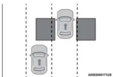
natural_image
Diagram showing two cars positioned at a junction with dashed lines indicating positions (no text or symbols)Rear Detection Zones
When the vehicle is started, the BSM Warning Light will momentarily illuminate in both outside rearview mirrors to let the driver know that the system is operational. The BSM system sensors operate when the vehicle is in any forward gear or REVERSE.
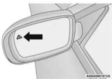
natural_image
Close-up of a car side panel with an arrow pointing left (no text or symbols)BSM Warning Light
The BSM detection zone covers approximately one lane width on both sides of the vehicle 12 ft (3.8 m). The zone length starts at the outside rearview mirror and extends approximately 10 ft (3 m) beyond the rear fascia/bumper of the vehicle. The BSM system monitors the detection zones on both sides of the vehicle when the vehicle speed reaches approximately 6 mph (10 km/h) or higher and will alert the driver of vehicles in these areas.
NOTE:
- The BSM system DOES NOT alert the driver about rapidly approaching vehicles that are outside the detection zones.
- The BSM system detection zone DOES NOT change if your vehicle is towing a trailer. Therefore, visually verify the adjacent lane is clear for both your vehicle and trailer before making a lane change. If the trailer or other object (i.e., bicycle, sports equipment) extends beyond the side of your vehicle, this may result in the BSM warning light randomly alerting on the trailer or even remaining illuminated the entire time the vehicle is in a forward gear ➞ page 144.
- The Blind Spot Monitoring (BSM) system may experience drop outs (blinking on and off) of the side mirror Warning Indicator lamps when a motorcycle or any small object remains at the side of the vehicle for extended periods of time (more than a couple of seconds).
The BSM system can become blocked if snow, ice, mud, or other road contaminations accumulate on the rear fascia/bumper where the radar sensors are located. The system may also detect blockage if the vehicle is operated in areas with extremely low radar returns such as a desert or parallel to a large elevation drop. If blockage is detected, a "Blind Spot Temporarily Unavailable, Wipe Rear Corners" message will display in the
cluster, both mirror lights will illuminate, and BSM and RCP alerts will not occur. This is normal operation. The system will automatically recover and resume function when the condition clears. To minimize system blockage, do not block the area of the rear fascia/bumper where the radar sensors are located with foreign objects (bumper stickers, bicycle racks, etc.) and keep it clear of road contaminations.
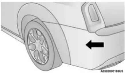
natural_image
Side view of a car wheel rim with an arrow pointing to the side (no text or symbols on the diagram itself)Sensor Location (Driver Side Shown)
The BSM system notifies the driver of objects in the detection zones by illuminating the BSM warning light located in the outside mirrors in addition to sounding an audible (chime) alert and reducing the radio volume if the corresponding turn signal is activated ➤ page 169.
The BSM system monitors the detection zone from three different entry points (side, rear, front) while driving to see if an alert is necessary. The BSM system will issue an alert during these types of zone entries.
Entering From The Side
Vehicles that move into your adjacent lanes from either side of the vehicle.
Entering From The Rear
Vehicles that come up from behind your vehicle on either side and enter the rear detection zone with a relative speed of less than 31 mph (50 km/h).
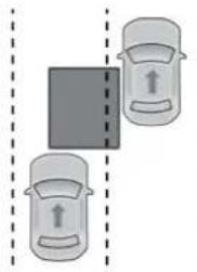
natural_image
Diagram showing two cars with directional arrows indicating movement or force, separated by a dashed line (no text or symbols)Rear Monitoring
A0502000167US
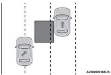
text_image
A0502000166USSide Monitoring
Overtaking Traffic
If you pass another vehicle slowly with a relative speed of less than 15 mph (24 km/h) and the vehicle remains in the blind spot for approximately 1.5 seconds, the warning light will be illuminated. If the difference in speed between the two vehicles is greater than 15 mph (24 km/h), the warning light will not illuminate.
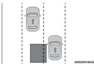
natural_image
Diagram showing two cars with directional arrows, one above a dark rectangular area and the other below (no text or symbols)Overtaking/Approaching
The BSM system is designed not to issue an alert on stationary objects such as guardrails, posts, walls, foliage, berms, etc. However, occasionally the system may alert on such objects. This is normal operation and your vehicle does not require service.
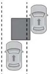
natural_image
Two cars with directional arrows indicating movement or movement, separated by a dashed line (no text or symbols)A0502000167US
Overtaking/Passing
The BSM system will not alert you of objects that are traveling in the opposite direction of the vehicle in adjacent lanes ↩ page 298.
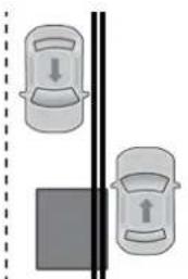
natural_image
Diagram showing two cars with directional arrows, one standing and one moving, separated by a vertical line (no text or symbols)A0502000165US
Opposing Traffic
WARNING!
The Blind Spot Monitoring system is only an aid to help detect objects in the blind spot zones. The BSM system is not designed to detect pedestrians, bicyclists, or animals. Even if your vehicle is equipped with the BSM system, always check your vehicle's mirrors, glance over your shoulder, and use your turn signal before changing lanes. Failure to do so can result in serious injury or death.
Rear Cross Path (RCP) Detection — If Equipped
RCP is intended to aid the driver when backing out of parking spaces where their vision of oncoming vehicles may be blocked. Proceed slowly and cautiously out of the parking space until the rear end of the vehicle is exposed. The RCP system will then have a clear view of the cross traffic and if an oncoming vehicle is detected, alert the driver.
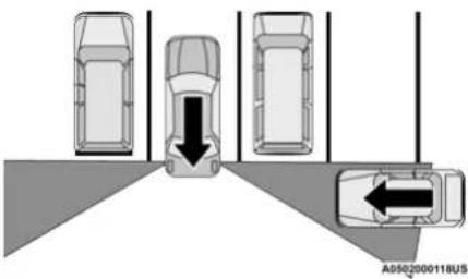
natural_image
Diagram showing four vehicles with directional arrows indicating movement or change, no text or symbols present.RCP Detection Zones
RCP monitors the rear detection zones on both sides of the vehicle, for objects that are moving toward the side of the vehicle with a minimum speed of approximately 3 mph (5 km/h), to objects moving a maximum of approximately 20 mph (32 km/h), such as in parking lot situations.
When RCP is on and the vehicle is in REVERSE, the driver is alerted using both the visual and audible alarms, including reducing the radio volume.
NOTE:
In a parking lot situation, oncoming vehicles can be blocked by vehicles parked on either side. If the sensors are blocked by other structures or vehicles, the system will not be able to alert the driver.
WARNING!
Rear Cross Path Detection (RCP) is not a backup aid system. It is intended to be used to help a driver detect an oncoming vehicle in a parking lot situation. Drivers must be careful when backing up, even when using RCP. Always check carefully behind your vehicle, look behind you, and be sure to check for pedestrians, animals, other vehicles, obstructions, and blind spots before backing up. Failure to do so can result in serious injury or death.
Blind Spot Modes
Blind Spot has three selectable modes of operation that are available in the Uconnect system.
Blind Spot Alert Lights Only
When operating in Blind Spot Alert mode, the BSM system will provide a visual alert in the appropriate side view mirror based on a detected object. However, when the system is operating in Rear Cross Path (RCP) mode, the system will respond with both visual and audible alerts when a detected object is
present. Whenever an audible alert is requested, the radio is muted.
Blind Spot Alert Lights/Chime
When operating in Blind Spot Alert Lights/Chime mode, the BSM system will provide a visual alert in the appropriate side view mirror based on a detected object. If the turn signal is then activated, and it corresponds to an alert present on that side of the vehicle, an audible chime will also be sounded. Whenever a turn signal and detected object are present on the same side at the same time, both the visual and audible alerts will be issued. In addition to the audible alert the radio (if on) will also be muted.
NOTE:
Whenever an audible alert is requested by the BSM system, the radio is also muted.
When the system is in RCP, the system shall respond with both visual and audible alerts when a detected object is present. Whenever an audible alert is requested, the radio is also muted. Turn/hazard signal status is ignored; the RCP state always requests the chime.
170 SAFETY
Blind Spot Alert Off
When the BSM system is turned off there will be no visual or audible alerts from either the BSM or RCP systems.
NOTE:
The BSM system will store the current operating mode when the vehicle is shut off. Each time the vehicle is started the previously stored mode will be recalled and used.
FORWARD COLLISION WARNING (FCW) WITH MITIGATION OPERATION — IF EQUIPPED
FCW with Mitigation provides the driver with audible warnings, visual warnings (within the instrument cluster display), and may apply a brake jerk to warn the driver when it detects a potential frontal collision. The warnings and limited braking are intended to provide the driver with enough time to react, avoid or mitigate the potential collision.
NOTE:
FCW monitors the information from the forward looking sensors, as well as the Electronic Stability Control (ESC) system, to calculate the probability of a forward collision. When the system determines that a forward collision is probable, the driver will be provided with audible and visual warnings and may provide a brake jerk warning. If the driver does not take action based upon these progressive warnings, then the system will provide a limited level of active braking to help slow the vehicle and mitigate the potential forward collision. If the driver reacts to the warnings by braking and the system determines that the driver intends to avoid the collision by braking but has not applied sufficient brake force, the system will compensate and provide additional brake force as required. If a Forward Collision Warning with Mitigation event begins at a speed below 20 mph (32 km/h), the system may provide the maximum or partial braking to mitigate the potential forward collision. If the Forward Collision Warning with Mitigation event stops the vehicle completely, the system will hold the vehicle at standstill for two seconds and then release the brakes.
BRAKE!
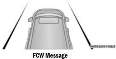
text_image
A0502000108US FCW MessageWhen the system determines a collision with the vehicle in front of you is no longer probable, the warning message will be deactivated ➤ page 298.
NOTE:
- The minimum speed for FCW activation is 1 mph (2 km/h).
-
The FCW alerts may be triggered on objects other than vehicles such as guard rails or sign posts based on the course prediction. This is expected and is a part of normal FCW activation and functionality.
-
It is unsafe to test the FCW system. To prevent such misuse of the system, after four Active Braking events within an ignition cycle, the Active Braking portion of FCW will be deactivated until the next ignition cycle.
- The FCW system is intended for on-road use only. If the vehicle is taken off-road, the FCW system should be deactivated to prevent unnecessary warnings due to the surroundings.
WARNING!
Forward Collision Warning (FCW) is not intended to avoid a collision on its own, nor can FCW detect every type of potential collision. The driver has the responsibility to avoid a collision by controlling the vehicle via braking and steering. Failure to follow this warning could lead to serious injury or death.
Turning FCW On Or Off
NOTE:
The default status of FCW is on; this allows the system to warn you of a possible collision with the vehicle in front of you.
The Forward Collision activation/deactivation is located in "Uconnect Settings" under "Safety
And Driving Assistance". Forward Collision can be checked or unchecked.
When FCW is selected off, there will be an "FCW OFF" icon that appears in the instrument cluster display.
Changing the FCW status to off prevents the system from warning you of a possible collision with the vehicle in front of you.
NOTE:
The FCW system's default state is on. The FCW system state is kept in memory from one ignition cycle to the next. If the system is turned off, it will remain off when the vehicle is restarted.
Changing FCW And Active Braking Status
The FCW Sensitivity and Active Braking settings are programmable through the Uconnect system → page 144.
The default status of FCW is the “Far” setting and the Active Braking is set to “on”; this allows the system to warn you of a possible collision with the vehicle in front of you when you are farther away and it applies limited braking. This gives you the most reaction time to avoid a possible collision.
Changing the FCW status to the “Near” setting, allows the system to warn you of a possible collision with the vehicle in front of you when you are much closer. This setting provides less reaction time than the “Far” setting, which allows for a more dynamic driving experience.
NOTE:
- The system will retain the last setting selected by the driver after ignition shut down.
- FCW may not react to irrelevant objects such as overhead objects, ground reflections, objects not in the path of the vehicle, stationary objects that are far away, oncoming traffic, or leading vehicles with the same or higher rate of speed.
- FCW disables in the same manner as ACC, and will display a screen indicating that the feature is unavailable when it has been disabled.
FCW Limited Warning
If the instrument cluster display reads "ACC/FCW Limited Functionality" or "ACC/FCW Limited Functionality Clean Front Windshield" momentarily, there may be a condition that
limits FCW functionality. Although the vehicle is still drivable under normal conditions, the active braking may not be fully available. Once the condition that limited the system performance is no longer present, the system will return to its full performance state. If the problem persists, see an authorized dealer.
Service FCW Warning
If the system turns off, and the instrument cluster display reads:
- ACC/FCW Unavailable Service Required
• Cruise/FCW Unavailable Service Required
This indicates there is an internal system fault. Although the vehicle is still drivable under normal conditions, have the system checked by an authorized dealer.
TIRE PRESSURE MONITORING SYSTEM (TPMS)
The Tire Pressure Monitoring System (TPMS) will warn the driver of a low tire pressure based on the vehicle recommended cold placard pressure.
The tire pressure will vary with temperature by about 1 psi (7 kPa) for every 12^ F ( 6.5^ C). This means that when the outside temperature decreases, the tire pressure will decrease. Tire pressure should always be set based on cold inflation tire pressure. This is defined as the tire pressure after the vehicle has not been driven for at least three hours, or driven less than 1 mile (1.6 km) after a three hour period. The cold tire inflation pressure must not exceed the maximum inflation pressure molded into the tire sidewall. The tire pressure will also increase as the vehicle is driven — this is normal and there should be no adjustment for this increased pressure.
See ▶ page 263 on how to properly inflate the vehicle's tires.
The TPMS will warn the driver of a low tire pressure if the tire pressure falls below the low-pressure warning limit for any reason, including low temperature effects and natural pressure loss through the tire.
The TPMS will continue to warn the driver of low tire pressure as long as the condition exists, and will not turn off until the tire pressure is at or above the recommended cold placard pressure. Once the low tire pressure warning (TPMS
Warning Light) illuminates, you must increase the tire pressure to the recommended cold placard pressure in order for the TPMS Warning Light to turn off. The system will automatically update and the TPMS Warning Light will turn off once the system receives the updated tire pressures. The vehicle may need to be driven for up to 20 minutes above 15 mph (24 km/h) in order for the TPMS to receive this information.
NOTE:
When filling warm tires, the tire pressure may need to be increased up to an additional 4 psi (28 kPa) above the recommended cold placard pressure in order to turn the TPMS Warning Light off.
For example, your vehicle may have a recommended cold (parked for more than three hours) placard pressure of 30 psi (207 kPa). If the ambient temperature is 68°F (20°C) and the measured tire pressure is 27 psi (186 kPa), a temperature drop to 20°F (-7°C) will decrease the tire pressure to approximately 23 psi (158 kPa). This tire pressure is sufficiently low enough to turn on the TPMS Warning Light. Driving the vehicle may cause the tire pressure to rise to approximately 27 psi (186 kPa), but the TPMS Warning Light will still
be on. In this situation, the TPMS Warning Light will turn off only after the tires are inflated to the vehicle's recommended cold placard pressure value.
CAUTION!
- The TPMS has been optimized for the original equipment tires and wheels. TPMS pressures and warning have been established for the tire size equipped on your vehicle. Undesirable system operation or sensor damage may result when using replacement equipment that is not of the same size, type, and/or style. The TPMS sensor is not designed for use on aftermarket wheels and may contribute to a poor overall system performance or sensor damage. Customers are encouraged to use Original Equipment Manufacturer (OEM) wheels to ensure proper TPMS feature operation.
- Using aftermarket tire sealants may cause the Tire Pressure Monitoring System (TPMS) sensor to become inoperable. After using an aftermarket tire sealant it is recommended that you take your vehicle to an authorized dealer to have your sensor function checked.
(Continued)
CAUTION! (Continued)
- After inspecting or adjusting the tire pressure always reinstall the valve stem cap. This will prevent moisture and dirt from entering the valve stem, which could damage the TPMS sensor.
NOTE:
- The TPMS is not intended to replace normal tire care and maintenance or to provide warning of a tire failure or condition.
- The TPMS should not be used as a tire pressure gauge while adjusting your tire pressure.
- Driving on a significantly underinflated tire causes the tire to overheat and can lead to tire failure. Underinflation also reduces fuel efficiency and tire tread life, and may affect the vehicle's handling and stopping ability.
- The TPMS is not a substitute for proper tire maintenance, and it is the driver's responsibility to maintain correct tire pressure using an accurate tire pressure gauge, even if underinflation has not reached the level to trigger illumination of the TPMS Warning Light.
- Seasonal temperature changes will affect tire pressure, and the TPMS will monitor the actual tire pressure in the tire.
The Tire Pressure Monitoring System (TPMS) uses wireless technology with wheel rim mounted electronic sensors to monitor tire pressure levels. Sensors, mounted to each wheel as part of the valve stem, transmit tire pressure readings to the receiver module page 298.
NOTE:
It is particularly important for you to check the tire pressure in all of the tires on your vehicle monthly and to maintain the proper pressure.
The TPMS consists of the following components:
- Receiver module.
- Four Tire Pressure Monitoring System sensors.
- Various Tire Pressure Monitoring System messages, which display in the instrument cluster.
- Tire Pressure Monitoring System Warning Light.
Tire Pressure Monitoring Low Pressure Warnings

The Tire Pressure Monitoring System (TPMS) Warning Light will illuminate in the instrument cluster and a chime will sound when tire pressure is low in one or more of the four active road tires. In addition, the instrument cluster will display an "Inflate to XX" message and a graphic showing the pressure values of each tire with the low tire pressure values shown in a different color.
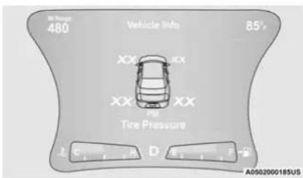
text_image
Mt Range 480 Vehicle Info 85° XX XX Tire Pressure A0502000185USTire Pressure Monitoring Display
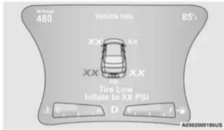
text_image
M Range 480 Vehicle Info 85° XX XX XX XX PBI Tire Low Inflate to XX PSI L C D A0502000186USLow Tire Pressure Monitoring Display
Should this occur, you should stop as soon as possible and inflate the tires with a low pressure condition (those shown in a different color in the instrument cluster graphic) to the vehicle's recommended cold placard pressure inflation value as shown in the "Inflate to XX" message. Once the system receives the updated tire pressures, the system will automatically update, the graphic display in the instrument cluster will change color back to the original color, and the TPMS Warning Light will turn off. The vehicle may need to be driven for up to 20 minutes above 15 mph (24 km/h) in order for the TPMS to receive this information.
NOTE:
When filling warm tires, the tire pressure may need to be increased up to an additional 4 psi (28 kPa) above the recommended cold placard pressure in order to turn the TPMS Warning Light off.
Service Tire Pressure System Warning
If a system fault is detected, the Tire Pressure Monitoring System (TPMS) Warning Light will flash on and off for 75 seconds and then remain on solid. The system fault will also sound a chime. In addition, the instrument cluster will display a "Service Tire Pressure System" message for a minimum of five seconds and then display dashes (- -) in place of the pressure value to indicate which sensor is not being received.
If the ignition switch is cycled, this sequence will repeat, providing the system fault still exists. If the system fault no longer exists, the TPMS Warning Light will no longer flash, and the "Service Tire Pressure System" message will no longer display, and a pressure value will display in place of the dashes. A system fault can occur due to any of the following:
- Signal interference due to electronic devices or driving next to facilities emitting the same radio frequencies as the TPMS sensors.
- Accumulation of snow or ice around the wheels or wheel housings.
- Using tire chains on the vehicle.
- Using wheels/tires not equipped with TPMS sensors.
Vehicles With Compact Spare
- The compact spare tire or non-matching full size does not have a Tire Pressure Monitoring System sensor. Therefore, the TPMS will not monitor the pressure in the compact spare tire.
- If you install the compact or non-matching full size spare tire in place of a road tire that has a pressure below the low-pressure warning limit, upon the next ignition key cycle, the TPMS Warning Light will remain on and a chime will sound. In addition, the graphic in the instrument cluster will still display a different color pressure value and an "Inflate to XX" message.
- After driving the vehicle for up to 20 minutes above 15 mph (24 km/h), the TPMS Warning Light will flash on and off for 75 seconds and then remain on solid. In addition, the instrument cluster will display
a "Service Tire Pressure System" message for five seconds and then display dashes (- -) in place of the pressure value.
- For each subsequent ignition key cycle, a chime will sound, the TPMS Warning Light will flash on and off for 75 seconds and then remain on solid, and the instrument cluster will display a "Service Tire Pressure System" message for five seconds and then display dashes (- -) in place of the pressure value.
- Once you repair or replace the original road tire and reinstall it on the vehicle in place of the compact spare or non-matching full size, the TPMS will update automatically. In addition, the TPMS Warning Light will turn off and the graphic in the instrument cluster will display a new pressure value instead of dashes (- -), as long as no tire pressure is below the low-pressure warning limit in any of the four active road tires. The vehicle may need to be driven for up to 20 minutes above 15 mph (24 km/h) in order for the TPMS to receive this information.
TPMS Deactivation — If Equipped
The Tire Pressure Monitoring System (TPMS) can be deactivated if replacing all four wheel and tire assemblies (road tires) with wheel and tire assemblies that do not have TPMS Sensors, such as when installing winter wheel and tire assemblies on your vehicle.
To deactivate the TPMS, first replace all four wheel and tire assemblies (road tires) with tires not equipped with Tire Pressure Monitoring System (TPMS) sensors. Then, drive the vehicle for 20 minutes above 15 mph (24 km/h). The TPMS will chime, the TPMS Warning Light will flash on and off for 75 seconds and then remain on. The instrument cluster will display the "Service Tire Pressure System" message and then display dashes (--) in place of the pressure values.
Beginning with the next ignition cycle, the TPMS will no longer chime or display the "Service Tire Pressure System" message in the instrument cluster but dashes (--) will remain in place of the pressure values.
To reactivate the TPMS, replace all four wheel and tire assemblies (road tires) with tires equipped with TPMS sensors. Then, drive the vehicle for up to 20 minutes above 15 mph (24 km/h). The TPMS will chime, the TPMS Warning Light will flash on and off for 75 seconds and then turn off. The instrument cluster will display the "Service Tire Pressure System" message and then display pressure values in place of the dashes. On the next ignition cycle the "Service Tire Pressure System" message will no longer be displayed as long as no system fault exists.
OCCUPANT RESTRAINT SYSTEMS
Some of the most important safety features in your vehicle are the restraint systems:
OCCUPANT RESTRAINT SYSTEMS FEATURES
- Seat Belt Systems
- Child Restraints
- Supplemental Restraint Systems (SRS) Air Bags
Some of the safety features described in this section may be standard equipment on some models, or may be optional equipment on others. If you are not sure, ask an authorized dealer.
IMPORTANT SAFETY PRECAUTIONS
Please pay close attention to the information in this section. It tells you how to use your restraint system properly, to keep you and your passengers as safe as possible.
Here are some simple steps you can take to minimize the risk of harm from a deploying air bag:
- Children 12 years old and under should always ride buckled up in the rear seat of a vehicle with a rear seat.
- A child who is not big enough to wear the vehicle seat belt properly must be secured in the appropriate child restraint or belt-positioning booster seat in a rear seating position ↩ page 193.
- If a child from 2 to 12 years old (not in a rear-facing child restraint) must ride in the front passenger seat, move the seat as far
back as possible and use the proper child restraint ➕ page 193.
- Never allow children to slide the shoulder belt behind them or under their arm.
- You should read the instructions provided with your child restraint to make sure that you are using it properly.
- All occupants should always wear their lap and shoulder belts properly.
- The driver and front passenger seats should be moved back as far as practical to allow the front air bags room to inflate.
- Do not lean against the door or window. If your vehicle has side air bags, and deployment occurs, the side air bags will inflate forcefully into the space between occupants and the door and occupants could be injured.
- If the air bag system in this vehicle needs to be modified to accommodate a disabled person, see ➤ page 294 for customer service contact information.
WARNING!
- Never place a rear-facing child restraint in front of an air bag. A deploying passenger front air bag can cause death or serious injury to a child 12 years or younger, including a child in a rear-facing child restraint.
- Never install a rear-facing child restraint in the front seat of a vehicle. Only use a rear-facing child restraint in the rear seat. If the vehicle does not have a rear seat, do not transport a rear-facing child restraint in that vehicle.
SEAT BELT SYSTEMS
Buckle up even though you are an excellent driver, even on short trips. Someone on the road may be a poor driver and could cause a collision that includes you. This can happen far away from home or on your own street.
Research has shown that seat belts save lives, and they can reduce the seriousness of injuries in a collision. Some of the worst injuries happen when people are thrown from the vehicle. Seat belts reduce the possibility of ejection and the risk of injury caused by striking the inside of the vehicle. Everyone in a motor vehicle should be belted at all times.
Enhanced Seat Belt Use Reminder System (BeltAlert)
Driver and Passenger BeltAlert (if equipped)
BeltAlert is a feature intended to remind the driver and outboard front seat passenger (if equipped with outboard front passenger seat BeltAlert) to buckle their seat belts. The BeltAlert feature is active whenever the ignition switch is in the START or ON/RUN position.
Initial Indication
If the driver is unbuckled when the ignition switch is first in the START or ON/RUN position, a chime will signal for a few seconds. If the driver or outboard front seat passenger (if equipped with outboard front passenger seat BeltAlert) is unbuckled when the ignition switch is first in the START or ON/RUN position the Seat Belt Reminder Light will turn on and remain on until both outboard front seat belts are buckled. The outboard front passenger seat BeltAlert is not active when an outboard front passenger seat is unoccupied.
SAFETY 177
BeltAlert Warning Sequence
The BeltAlert warning sequence is activated when the vehicle is moving above a specified vehicle speed range and the driver or outboard front seat passenger is unbuckled (if equipped with outboard front passenger seat BeltAlert) (the outboard front passenger seat BeltAlert is not active when the outboard front passenger seat is unoccupied). The BeltAlert warning sequence starts by blinking the Seat Belt Reminder Light and sounding an intermittent chime. Once the BeltAlert warning sequence has completed, the Seat Belt Reminder Light will remain on until the seat belts are buckled. The BeltAlert warning sequence may repeat based on vehicle speed until the driver and occupied outboard front seat passenger seat belts are buckled. The driver should instruct all occupants to buckle their seat belts.
Change of Status
If the driver or outboard front seat passenger (if equipped with outboard front passenger seat BeltAlert) unbuckles their seat belt while the vehicle is traveling, the BeltAlert warning sequence will begin until the seat belts are buckled again.
The outboard front passenger seat BeltAlert is not active when the outboard front passenger seat is unoccupied. BeltAlert may be triggered when an animal or other items are placed on the outboard front passenger seat or when the seat is folded flat (if equipped). It is recommended that pets be restrained in the rear seat (if equipped) in pet harnesses or pet carriers that are secured by seat belts, and cargo is properly stowed.
BeltAlert can be activated or deactivated by an authorized dealer. FCA US LLC does not recommend deactivating BeltAlert.
NOTE:
If BeltAlert has been deactivated and the driver or outboard front seat passenger (if equipped with outboard front passenger seat BeltAlert) is unbuckled the Seat Belt Reminder Light will turn on and remain on until the driver and outboard front seat passenger seat belts are buckled.
Lap/Shoulder Belts
All seating positions in your vehicle are equipped with lap/shoulder belts.
The seat belt webbing retractor will lock only during very sudden stops or collisions. This feature allows the shoulder part of the seat belt
to move freely with you under normal conditions. However, in a collision the seat belt will lock and reduce your risk of striking the inside of the vehicle or being thrown out of the vehicle.
WARNING!
- Relying on the air bags alone could lead to more severe injuries in a collision. The air bags work with your seat belt to restrain you properly. In some collisions, the air bags won't deploy at all. Always wear your seat belt even though you have air bags.
- In a collision, you and your passengers can suffer much greater injuries if you are not properly buckled up. You can strike the interior of your vehicle or other passengers, or you can be thrown out of the vehicle. Always be sure you and others in your vehicle are buckled up properly.
- It is dangerous to ride in a cargo area, inside or outside of a vehicle. In a collision, people riding in these areas are more likely to be seriously injured or killed.
(Continued)
WARNING! (Continued)
- Do not allow people to ride in any area of your vehicle that is not equipped with seats and seat belts.
- Be sure everyone in your vehicle is in a seat and using a seat belt properly. Occupants, including the driver, should always wear their seat belts whether or not an air bag is also provided at their seating position to minimize the risk of severe injury or death in the event of a crash.
- Wearing your seat belt incorrectly could make your injuries in a collision much worse. You might suffer internal injuries, or you could even slide out of the seat belt. Follow these instructions to wear your seat belt safely and to keep your passengers safe, too.
- Two people should never be belted into a single seat belt. People belted together can crash into one another in a collision, hurting one another badly. Never use a lap/shoulder belt or a lap belt for more than one person, no matter what their size.
WARNING!
- A lap belt worn too high can increase the risk of injury in a collision. The seat belt forces won't be at the strong hip and pelvic bones, but across your abdomen. Always wear the lap part of your seat belt as low as possible and keep it snug.
- A twisted seat belt may not protect you properly. In a collision, it could even cut into you. Be sure the seat belt is flat against your body, without twists. If you can't straighten a seat belt in your vehicle, take it to an authorized dealer immediately and have it fixed.
- A seat belt that is buckled into the wrong buckle will not protect you properly. The lap portion could ride too high on your body, possibly causing internal injuries. Always buckle your seat belt into the buckle nearest you.
- A seat belt that is too loose will not protect you properly. In a sudden stop, you could move too far forward, increasing the possibility of injury. Wear your seat belt snugly.
WARNING! (Continued)
- A seat belt that is worn under your arm is dangerous. Your body could strike the inside surfaces of the vehicle in a collision, increasing head and neck injury. A seat belt worn under the arm can cause internal injuries. Ribs aren't as strong as shoulder bones. Wear the seat belt over your shoulder so that your strongest bones will take the force in a collision.
- A shoulder belt placed behind you will not protect you from injury during a collision. You are more likely to hit your head in a collision if you do not wear your shoulder belt. The lap and shoulder belt are meant to be used together.
- A frayed or torn seat belt could rip apart in a collision and leave you with no protection. Inspect the seat belt system periodically, checking for cuts, frays, or loose parts. Damaged parts must be replaced immediately. Do not disassemble or modify the seat belt system. Seat belt assemblies must be replaced after a collision.
(Continued)
Lap/Shoulder Belt Operating Instructions
- Enter the vehicle and close the door. Sit back and adjust the seat.
- The seat belt latch plate is above the back of the front seat, and next to your arm in the rear seat (for vehicles equipped with a rear seat). Grab the latch plate and pull out the seat belt. Slide the latch plate up the webbing as far as necessary to allow the seat belt to go around your lap.
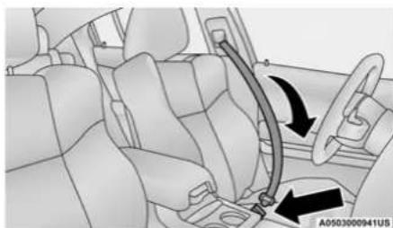
natural_image
Interior view of a car showing seatbelt and belt drive mechanism (no text or symbols)Pulling Out The Latch Plate
- When the seat belt is long enough to fit, insert the latch plate into the buckle until you hear a "click."
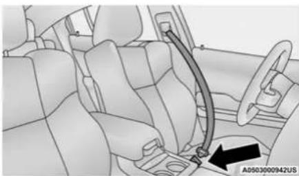
natural_image
Interior view of a car showing seatbelt and dashboard (no text or symbols visible)Inserting Latch Plate Into Buckle
- Position the lap belt so that it is snug and lies low across your hips, below your abdomen. To remove slack in the lap belt portion, pull up on the shoulder belt. To loosen the lap belt if it is too tight, tilt the latch plate and pull on the lap belt. A snug seat belt reduces the risk of sliding under the seat belt in a collision.
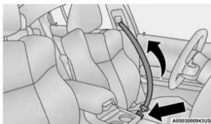
natural_image
Interior view of a car showing seatbelt and belt drive mechanism (no text or symbols)Positioning The Lap Belt
-
Position the shoulder belt across the shoulder and chest with minimal, if any slack so that it is comfortable and not resting on your neck. The retractor will withdraw any slack in the shoulder belt.
-
To release the seat belt, push the red button on the buckle. The seat belt will automatically retract to its stowed position. If necessary, slide the latch plate down the webbing to allow the seat belt to retract fully.
Lap/Shoulder Belt Untwisting Procedure
Use the following procedure to untwist a twisted lap/shoulder belt.
- Position the latch plate as close as possible to the anchor point.
- At about 6 to 12 inches (15 to 30 cm) above the latch plate, grab and twist the seat belt webbing 180 degrees to create a fold that begins immediately above the latch plate.
- Slide the latch plate upward over the folded webbing. The folded webbing must enter the slot at the top of the latch plate.
- Continue to slide the latch plate up until it clears the folded webbing and the seat belt is no longer twisted.
Adjustable Upper Shoulder Belt Anchorage
In the driver and outboard front passenger seats, the top of the shoulder belt can be adjusted upward or downward to position the seat belt away from your neck. Push or squeeze the anchorage button to release the anchorage, and move it up or down to the position that serves you best.
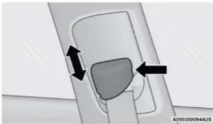
natural_image
Diagram showing a mechanical component with two arrows indicating direction, no text or symbols presentAdjustable Anchorage
As a guide, if you are shorter than average, you will prefer the shoulder belt anchorage in a lower position, and if you are taller than average, you will prefer the shoulder belt anchorage in a higher position. After you release the anchorage button, try to move it up or down to make sure that it is locked in position.
NOTE:
The adjustable upper shoulder belt anchorage is equipped with an Easy Up feature. This feature allows the shoulder belt anchorage to be adjusted in the upward position without pushing or squeezing the release button. To verify the shoulder belt anchorage is latched, pull downward on the shoulder belt anchorage until it is locked into position.
WARNING!
- Wearing your seat belt incorrectly could make your injuries in a collision much worse. You might suffer internal injuries, or you could even slide out of the seat belt. Follow these instructions to wear your seat belt safely and to keep your passengers safe, too.
- Position the shoulder belt across the shoulder and chest with minimal, if any slack so that it is comfortable and not resting on your neck. The retractor will withdraw any slack in the shoulder belt.
(Continued)
WARNING! (Continued)
- Misadjustment of the seat belt could reduce the effectiveness of the safety belt in a crash.
- Always make all seat belt height adjustments when the vehicle is stationary.
Seat Belt Extender
If a seat belt is not long enough to fit properly, even when the webbing is fully extended and the adjustable upper shoulder belt anchorage (if equipped) is in its lowest position, an authorized dealer can provide you with a Seat Belt Extender. The Seat Belt Extender should be used only if the existing seat belt is not long enough. When the Seat Belt Extender is not required for a different occupant, it must be removed.
WARNING!
- ONLY use a Seat Belt Extender if it is physically required in order to properly fit the original seat belt system. DO NOT USE the Seat Belt Extender if, when worn, the distance between the front edge of the Seat Belt Extender buckle and the center of the occupant's body is LESS than 6 inches.
(Continued)
WARNING! (Continued)
- Using a Seat Belt Extender when not needed can increase the risk of serious injury or death in a collision. Only use the Seat Belt Extender when the lap belt is not long enough and only use in the recommended seating positions. Remove and store the Seat Belt Extender when not needed.
Seat Belts And Pregnant Women
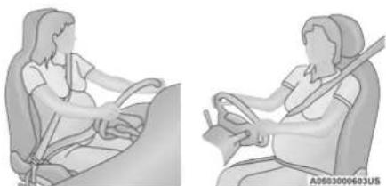
natural_image
Illustration of a person seated in a car, showing seatbelt and seatbelt (no text or symbols)Seat Belts and Pregnant Women
Seat belts must be worn by all occupants including pregnant women: the risk of injury in the event of an accident is reduced for the mother and the unborn child if they are wearing a seat belt.
Position the lap belt snug and low below the abdomen and across the strong bones of the hips. Place the shoulder belt across the chest and away from the neck. Never place the shoulder belt behind the back or under the arm.
Seat Belt Pretensioner
The front outboard seat belt system is equipped with pretensioning devices that are designed to remove slack from the seat belt in the event of a collision. These devices may improve the performance of the seat belt by removing slack from the seat belt early in a collision.
Pretensioners work for all size occupants, including those in child restraints.
NOTE:
These devices are not a substitute for proper seat belt placement by the occupant. The seat belt still must be worn snugly and positioned properly.
The pretensioners are triggered by the Occupant Restraint Controller (ORC). Like the air bags, the pretensioners are single use items. A deployed pretensioner or a deployed air bag must be replaced immediately.
Energy Management Feature
The front outboard seat belt system is equipped with an Energy Management feature that may help further reduce the risk of injury in the event of a collision. The seat belt system has a retractor assembly that is designed to release webbing in a controlled manner.
Switchable Automatic Locking Retractors (ALR)
The seat belts in the passenger seating positions are equipped with a Switchable Automatic Locking Retractor (ALR) which is used to secure a child restraint system page 202.
The figure below illustrates the locking feature for each seating position.
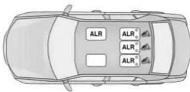
text_image
ALR ALR₀° ALR₀° ALR₀°AD583000945US
ALR – Switchable Automatic Locking Retractor
If the passenger seating position is equipped with an ALR and is being used for normal usage, only pull the seat belt webbing out far enough to comfortably wrap around the occupant's mid-section so as to not activate the ALR. If the ALR is activated, you will hear a clicking sound as the seat belt retracts. Allow the webbing to retract completely in this case and then carefully pull out only the amount of webbing necessary to comfortably wrap around the occupant's mid-section. Slide the latch plate into the buckle until you hear a "click."
In Automatic Locking Mode, the shoulder belt is automatically pre-locked. The seat belt will still retract to remove any slack in the shoulder belt. Use the Automatic Locking Mode anytime a child restraint is installed in a seating position that has a seat belt with this feature. Children 12 years old and under should always be properly restrained in the rear seat of a vehicle with a rear seat.
WARNING!
- Never place a rear-facing child restraint in front of an air bag. A deploying passenger front air bag can cause death or serious injury to a child 12 years or younger, including a child in a rear-facing child restraint.
(Continued)
WARNING! (Continued)
- Never install a rear-facing child restraint in the front seat of a vehicle. Only use a rear-facing child restraint in the rear seat. If the vehicle does not have a rear seat, do not transport a rear-facing child restraint in that vehicle.
How To Engage The Automatic Locking Mode
- Buckle the combination lap and shoulder belt.
- Grab the shoulder portion and pull downward until the entire seat belt is extracted.
- Allow the seat belt to retract. As the seat belt retracts, you will hear a clicking sound. This indicates the seat belt is now in the Automatic Locking Mode.
How To Disengage The Automatic Locking Mode
Unbuckle the combination lap/shoulder belt and allow it to retract completely to disengage the Automatic Locking Mode and activate the vehicle sensitive (emergency) locking mode.
WARNING!
- The seat belt assembly must be replaced if the switchable Automatic Locking Retractor (ALR) feature or any other seat belt function is not working properly when checked according to the procedures in the Service Manual.
- Failure to replace the seat belt assembly could increase the risk of injury in collisions.
- Do not use the Automatic Locking Mode to restrain occupants who are wearing the seat belt or children who are using booster seats. The locked mode is only used to install rear-facing or forward-facing child restraints that have a harness for restraining the child.
SUPPLEMENTAL RESTRAINT SYSTEMS (SRS)
Some of the safety features described in this section may be standard equipment on some models, or may be optional equipment on others. If you are not sure, ask an authorized dealer.
The air bag system must be ready to protect you in a collision. The Occupant Restraint Controller (ORC) monitors the internal circuits and interconnecting wiring associated with the electrical Air Bag System Components. Your vehicle may be equipped with the following Air Bag System Components:
Air Bag System Components
• Occupant Restraint Controller (ORC)
• Air Bag Warning Light
• Steering Wheel and Column
- Instrument Panel
- Knee Impact Bolsters
- Driver and Front Passenger Air Bags
- Seat Belt Buckle Switch
• Supplemental Side Air Bags
• Supplemental Knee Air Bags
• Front and Side Impact Sensors
- Seat Belt Pretensioners
- Seat Track Position Sensors
Air Bag Warning Light

The Occupant Restraint Controller (ORC) monitors the readiness of the electronic parts of the air bag system whenever the ignition switch is in the
START or ON/RUN position. If the ignition switch is in the OFF position or in the ACC position, the air bag system is not on and the air bags will not inflate.
The ORC contains a backup power supply system that may deploy the air bag system even if the battery loses power or it becomes disconnected prior to deployment.
The ORC turns on the Air Bag Warning Light in the instrument panel for approximately four to eight seconds for a self-check when the ignition switch is first in the ON/RUN position. After the self-check, the Air Bag Warning Light will turn off. If the ORC detects a malfunction in any part of the system, it turns on the Air Bag Warning Light, either momentarily or continuously. A single chime will sound to alert you if the light comes on again after initial startup.
The ORC also includes diagnostics that will illuminate the instrument panel Air Bag Warning Light if a malfunction is detected that could affect the air bag system. The diagnostics also record the nature of the malfunction. While the air bag system is designed to be maintenance free, if any of the following occurs, have an authorized dealer service the air bag system immediately.
- The Air Bag Warning Light does not come on during the four to eight seconds when the ignition switch is first in the ON/RUN position.
- The Air Bag Warning Light remains on after the four to eight-second interval.
- The Air Bag Warning Light comes on intermittently or remains on while driving.
NOTE:
If the speedometer, tachometer, or any engine related gauges are not working, the Occupant Restraint Controller (ORC) may also be disabled. In this condition the air bags may not be ready to inflate for your protection. Have an authorized dealer service the air bag system immediately.
WARNING!
Ignoring the Air Bag Warning Light in your instrument panel could mean you won't have the air bag system to protect you in a collision. If the light does not come on as a bulb check when the ignition is first turned on, stays on after you start the vehicle, or if it comes on as you drive, have an authorized dealer service the air bag system immediately.
Redundant Air Bag Warning Light

If a fault with the Air Bag Warning Light is detected, which could affect the Supplemental Restraint System (SRS), the Redundant Air Bag Warning Light will illuminate on the instrument panel. The Redundant Air Bag Warning Light will stay on until the fault is cleared. In addition, a single chime will sound to alert you that the Redundant Air Bag Warning Light has come on and a fault has been detected. If the Redundant Air Bag Warning Light comes on intermittently or remains on while driving have an authorized dealer service the vehicle immediately
page 82.
Front Air Bags
This vehicle has front air bags and lap/shoulder belts for both the driver and front passenger. The front air bags are a supplement to the seat belt restraint systems. The driver front air bag is mounted in the center of the steering wheel. The passenger front air bag is mounted in the instrument panel, above the glove compartment. The words "SRS AIRBAG" or "AIRBAG" are embossed on the air bag covers.
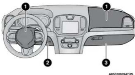
text_image
Diagram of a car interior with numbered components for identificationFront Air Bag/Knee Bolster Locations
1 – Driver And Passenger Front Air Bags
2 – Passenger Knee Impact Bolster
3 – Driver Knee Impact Bolster/Supplemental Driver Knee Air Bag
WARNING!
- Being too close to the steering wheel or instrument panel during front air bag deployment could cause serious injury, including death. Air bags need room to inflate. Sit back, comfortably extending your arms to reach the steering wheel or instrument panel.
- Never place a rear-facing child restraint in front of an air bag. A deploying passenger front air bag can cause death or serious injury to a child 12 years or younger, including a child in a rear-facing child restraint.
- Never install a rear-facing child restraint in the front seat of a vehicle. Only use a rear-facing child restraint in the rear seat. If the vehicle does not have a rear seat, do not transport a rear-facing child restraint in that vehicle.
Driver And Passenger Front Air Bag Features
The Advanced Front Air Bag system has multistage driver and front passenger air bags. This system provides output appropriate to the severity and type of collision as determined by the Occupant
Restraint Controller (ORC), which may receive information from the front impact sensors (if equipped) or other system components.
The first stage inflator is triggered immediately during an impact that requires air bag deployment. A low energy output is used in less severe collisions. A higher energy output is used for more severe collisions.
This vehicle may be equipped with a driver and/or front passenger seat belt buckle switch that detects whether the driver or front passenger seat belt is buckled. The seat belt buckle switch may adjust the inflation rate of the Advanced Front Air Bags.
This vehicle may be equipped with driver and/or front passenger seat track position sensors that may adjust the inflation rate of the Advanced Front Air Bags based upon seat position.
WARNING!
- No objects should be placed over or near the air bag on the instrument panel or steering wheel because any such objects could cause harm if the vehicle is in a collision severe enough to cause the air bag to inflate.
(Continued)
WARNING! (Continued)
- Do not put anything on or around the air bag covers or attempt to open them manually. You may damage the air bags and you could be injured because the air bags may no longer be functional. The protective covers for the air bag cushions are designed to open only when the air bags are inflating.
- Relying on the air bags alone could lead to more severe injuries in a collision. The air bags work with your seat belt to restrain you properly. In some collisions, air bags won't deploy at all. Always wear your seat belts even though you have air bags.
Front Air Bag Operation
Front Air Bags are designed to provide additional protection by supplementing the seat belts. Front air bags are not expected to reduce the risk of injury in rear, side, or rollover collisions. The front air bags will not deploy in all frontal collisions, including some that may produce substantial vehicle damage — for example, some pole collisions, truck underrides, and angle offset collisions.
On the other hand, depending on the type and location of impact, front air bags may deploy in crashes with little vehicle front-end damage but that produce a severe initial deceleration.
Because air bag sensors measure vehicle deceleration over time, vehicle speed and damage by themselves are not good indicators of whether or not an air bag should have deployed.
Seat belts are necessary for your protection in all collisions, and also are needed to help keep you in position, away from an inflating air bag.
When the Occupant Restraint Controller (ORC) detects a collision requiring the front air bags, it signals the inflator units. A large quantity of non-toxic gas is generated to inflate the front air bags.
The steering wheel hub trim cover and the upper passenger side of the instrument panel separate and fold out of the way as the air bags inflate to their full size. The front air bags fully inflate in less time than it takes to blink your eyes. The front air bags then quickly deflate while helping to restrain the driver and front passenger.
Knee Impact Bolsters
The Knee Impact Bolsters help protect the knees of the driver and front passenger, and position the front occupants for improved interaction with the front air bags.
WARNING!
- Do not drill, cut, or tamper with the knee impact bolsters in any way.
- Do not mount any accessories to the knee impact bolsters such as alarm lights, stereos, citizen band radios, etc.
Supplemental Driver Knee Air Bag
This vehicle is equipped with a Supplemental Driver Knee Air Bag mounted in the instrument panel below the steering column. The Supplemental Driver Knee Air Bag provides enhanced protection during a frontal impact by working together with the seat belts, pretensioners, and front air bags.
Supplemental Side Air Bags
Supplemental Seat-Mounted Side Air Bags (SABs)
This vehicle is equipped with Supplemental Seat-Mounted Side Air Bags (SABs).
Supplemental Seat-Mounted Side Air Bags (SABs) are located in the outboard side of the front seats. The SABs are marked with "SRS AIRBAG" or "AIRBAG" on a label or on the seat trim on the outboard side of the seats.
The SABs may help to reduce the risk of occupant injury during certain side impacts, in addition to the injury reduction potential provided by the seat belts and body structure.
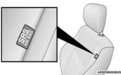
text_image
SRS AIRLPG A0503000938USFront Supplemental Seat-Mounted Side Air Bag Label
When the SAB deploys, it opens the seam on the outboard side of the seatback's trim cover. The inflating SAB deploys through the seat seam into the space between the occupant and the door. The SAB moves at a very high speed and with such a high force that it could injure occupants if they are not seated properly, or if items are positioned in the area where the SAB inflates. Children are at an even greater risk of injury from a deploying air bag.
WARNING!
Do not use accessory seat covers or place objects between you and the Side Air Bags; the performance could be adversely affected and/or objects could be pushed into you, causing serious injury.
Supplemental Side Air Bag Inflatable Curtains (SABICs)
This vehicle is equipped with Supplemental Side Air Bag Inflatable Curtains (SABICs).
Supplemental Side Air Bag Inflatable Curtains (SABICs) are located above the side windows. The trim covering the SABICs is labeled "SRS AIRBAG" or "AIRBAG."
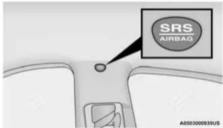
text_image
SRS AIRBAG A0503000939USSupplemental Side Air Bag Inflatable Curtain (SABIC) Label Location
SABICs may help reduce the risk of head and other injuries to front and rear seat outboard occupants in certain side impacts, in addition to the injury reduction potential provided by the seat belts and body structure.
The SABIC deploys downward, covering the side windows. An inflating SABIC pushes the outside edge of the headliner out of the way and covers the window. The SABICs inflate with enough force to injure occupants if they are not belted and seated properly, or if items are positioned in the area where the SABICs inflate. Children are at an even greater risk of injury from a deploying air bag.
The SABICs may help reduce the risk of partial or complete ejection of vehicle occupants through side windows in certain side impact events.
WARNING!
- Do not mount equipment, or stack luggage or other cargo up high enough to block the deployment of the SABICs. The trim covering above the side windows where the SABIC and its deployment path are located should remain free from any obstructions.
- In order for the SABICs to work as intended, do not install any accessory items in your vehicle which could alter the roof. Do not add an aftermarket sunroof to your vehicle. Do not add roof racks that require permanent attachments (bolts or screws) for installation on the vehicle roof. Do not drill into the roof of the vehicle for any reason.
Side Impacts
The Side Air Bags are designed to activate in certain side impacts. The Occupant Restraint Controller (ORC) determines whether the deployment of the Side Air Bags in a particular impact event is appropriate, based on the
severity and type of collision. The side impact sensors aid the ORC in determining the appropriate response to impact events. The system is calibrated to deploy the Side Air Bags on the impact side of the vehicle during impacts that require Side Air Bag occupant protection. In side impacts, the Side Air Bags deploy independently; a left side impact deploys the left Side Air Bags only and a right-side impact deploys the right Side Air Bags only. Vehicle damage by itself is not a good indicator of whether or not Side Air Bags should have deployed.
The Side Air Bags will not deploy in all side collisions, including some collisions at certain angles, or some side collisions that do not impact the area of the passenger compartment. The Side Air Bags may deploy during angled or offset frontal collisions where the front air bags deploy.
Side Air Bags are a supplement to the seat belt restraint system. Side Air Bags deploy in less time than it takes to blink your eyes.
WARNING!
- Occupants, including children, who are up against or very close to Side Air Bags can be seriously injured or killed. Occupants, including children, should never lean on or sleep against the door, side windows, or area where the side air bags inflate, even if they are in an infant or child restraint.
- Seat belts (and child restraints where appropriate) are necessary for your protection in all collisions. They also help keep you in position, away from an inflating Side Air Bag. To get the best protection from the Side Air Bags, occupants must wear their seat belts properly and sit upright with their backs against the seats. Children must be properly restrained in a child restraint or booster seat that is appropriate for the size of the child.
WARNING!
- Side Air Bags need room to inflate. Do not lean against the door or window. Sit upright in the center of the seat.
- Being too close to the Side Air Bags during deployment could cause you to be severely injured or killed.
- Relying on the Side Air Bags alone could lead to more severe injuries in a collision. The Side Air Bags work with your seat belt to restrain you properly. In some collisions, Side Air Bags won't deploy at all. Always wear your seat belt even though you have Side Air Bags.
NOTE:
Air bag covers may not be obvious in the interior trim, but they will open during air bag deployment.
Rollover Events
Side Air Bags and seat belt pretensioners are designed to activate in certain rollover events. The Occupant Restraint Controller (ORC) determines whether deployment in a particular rollover event is appropriate, based on the severity and type of collision. Vehicle damage by itself is not a good indicator of whether or not Side Air Bags and seat belt pretensioners should have deployed.
The Side Air Bags and seat belt pretensioners will not deploy in all rollover events. The rollover sensing system determines if a rollover event may be in progress and whether deployment is appropriate. In the event the vehicle experiences a rollover or near rollover event, and deployment is appropriate, the rollover sensing system will deploy the Side Air Bags and seat belt pretensioners on both sides of the vehicle.
The SABICs may help reduce the risk of partial or complete ejection of vehicle occupants through side windows in certain rollover or side impact events.
Air Bag System Components
NOTE:
The Occupant Restraint Controller (ORC) monitors the internal circuits and interconnecting wiring associated with electrical Air Bag System Components listed below:
• Occupant Restraint Controller (ORC)
• Air Bag Warning Light
• Steering Wheel and Column
- Instrument Panel
- Knee Impact Bolsters
- Driver and Front Passenger Air Bags
- Seat Belt Buckle Switch
• Supplemental Side Air Bags
• Supplemental Knee Air Bags
• Front and Side Impact Sensors
- Seat Belt Pretensioners
- Seat Track Position Sensors
If A Deployment Occurs
The front air bags are designed to deflate immediately after deployment.
NOTE:
Front and/or side air bags will not deploy in all collisions. This does not mean something is wrong with the air bag system.
If you do have a collision which deploys the air bags, any or all of the following may occur:
- The air bag material may sometimes cause abrasions and/or skin reddening to the occupants as the air bags deploy and unfold. The abrasions are similar to friction rope burns or those you might get sliding along a carpet or gymnasium floor. They are not caused by contact with chemicals. They are not permanent and normally heal quickly. However, if you haven't healed significantly within a few days, or if you have any blistering, see your doctor immediately.
- As the air bags deflate, you may see some smoke-like particles. The particles are a normal by-product of the process that generates the non-toxic gas used for air bag inflation. These airborne particles may irritate the skin, eyes, nose, or throat. If you have skin or
eye irritation, rinse the area with cool water. For nose or throat irritation, move to fresh air. If the irritation continues, see your doctor. If these particles settle on your clothing, follow the garment manufacturer's instructions for cleaning.
Do not drive your vehicle after the air bags have deployed. If you are involved in another collision, the air bags will not be in place to protect you.
WARNING!
Deployed air bags and seat belt pretensioners cannot protect you in another collision. Have the air bags, seat belt pretensioners, and the seat belt retractor assemblies replaced by an authorized dealer immediately. Also, have the Occupant Restraint Controller System serviced as well.
NOTE:
- Air bag covers may not be obvious in the interior trim, but they will open during air bag deployment.
- After any collision, the vehicle should be taken to an authorized dealer immediately.
Enhanced Accident Response System
In the event of an impact, if the communication network remains intact, and the power remains intact, depending on the nature of the event, the Occupant Restraint Controller (ORC) will determine whether to have the Enhanced Accident Response System perform the following functions:
- Cut off fuel to the engine (if equipped).
- Cut off battery power to the electric motor (if equipped).
- Flash hazard lights as long as the battery has power.
- Turn on the interior lights, which remain on as long as the battery has power or for 15 minutes from the intervention of the Enhanced Accident Response System.
- Unlock the power door locks.
Your vehicle may also be designed to perform any of these other functions in response to the Enhanced Accident Response System:
- Turn off the Fuel Filter Heater, Turn off the HVAC Blower Motor, Close the HVAC Circulation Door
- Cut off battery power to the:
- Engine
• Electric Motor (if equipped)
• Electric power steering - Brake booster
• Electric park brake
• Automatic transmission gear selector - Horn
- Front wiper
- Headlamp washer pump
NOTE:
After an accident, remember to cycle the ignition to the STOP (OFF/LOCK) position and remove the key from the ignition switch to avoid draining the battery. Carefully check the vehicle for fuel leaks in the engine compartment and on the ground near the engine compartment and fuel tank before resetting the system and starting the engine. If there are no fuel leaks or damage to the vehicle electrical devices (e.g. headlights) after an accident, reset the system by following the procedure described below. If you have any doubt, contact an authorized dealer.
Enhanced Accident Response System Reset Procedure
In order to reset the Enhanced Accident Response System functions after an event, the ignition switch must be changed from ignition START or ON/RUN to ignition OFF. Carefully check the vehicle for fuel leaks in the engine compartment and on the ground near the engine compartment and fuel tank before resetting the system and starting the engine.
After an accident, if the vehicle will not start after performing the reset procedure, the vehicle must be towed to an authorized dealer to be inspected and to have the Enhanced Accident Response System reset.
Maintaining Your Air Bag System
WARNING!
- Modifications to any part of the air bag system could cause it to fail when you need it. You could be injured if the air bag system is not there to protect you. Do not modify the components or wiring, including adding any kind of badges or stickers to the steering wheel hub trim cover or the upper passenger side of the instrument panel. Do not modify the front fascia/bumper, vehicle body structure, or add aftermarket side steps or running boards.
- It is dangerous to try to repair any part of the air bag system yourself. Be sure to tell anyone who works on your vehicle that it has an air bag system.
(Continued)
WARNING! (Continued)
- Do not attempt to modify any part of your air bag system. The air bag may inflate accidentally or may not function properly if modifications are made. Take your vehicle to an authorized dealer for any air bag system service. If your seat, including your trim cover and cushion, needs to be serviced in any way (including removal or loosening/tightening of seat attachment bolts), take the vehicle to an authorized dealer. Only manufacturer approved seat accessories may be used. If it is necessary to modify the air bag system for persons with disabilities, contact an authorized dealer.
Event Data Recorder (EDR)
This vehicle is equipped with an event data recorder (EDR). The main purpose of an EDR is to record, in certain crash or near crash-like situations, such as an air bag deployment or hitting a road obstacle, data that will assist in understanding how a vehicle's systems performed. The EDR is designed to record data related to vehicle dynamics and safety systems for a short period of time, typically 30 seconds or less. The EDR in this vehicle is designed to record such data as:
- How various systems in your vehicle were operating;
- Whether or not the driver and passenger safety belts were buckled/fastened;
- How far (if at all) the driver was depressing the accelerator and/or brake pedal; and,
- How fast the vehicle was traveling.
These data can help provide a better understanding of the circumstances in which crashes and injuries occur.
NOTE:
EDR data are recorded by your vehicle only if a non-trivial crash situation occurs; no data are recorded by the EDR under normal driving conditions and no personal data (e.g., name, gender, age, and crash location) are recorded. However, other parties, such as law enforcement, could combine the EDR data with the type of personally identifying data routinely acquired during a crash investigation.
To read data recorded by an EDR, special equipment is required, and access to the vehicle or the EDR is needed. In addition to the vehicle manufacturer, other parties, such as law enforcement, that have the special equipment, can read the information if they have access to the vehicle or the EDR.
CHILD RESTRAINTS
Everyone in your vehicle needs to be buckled up at all times, including babies and children. Every state in the United States, and every Canadian province, requires that small children ride in proper restraint systems. This is the law, and you can be prosecuted for ignoring it.
Children 12 years or younger should ride properly buckled up in a rear seat, if available. According to crash statistics, children are safer when properly restrained in the rear seats rather than in the front.
WARNING!
In a collision, an unrestrained child can become a projectile inside the vehicle. The force required to hold even an infant on your lap could become so great that you could not hold the child, no matter how strong you are. The child and others could be badly injured or killed. Any child riding in your vehicle should be in a proper restraint for the child's size.
There are different sizes and types of restraints for children from newborn size to the child almost large enough for an adult safety belt. Always check the child seat Owner's Manual to make sure you have the correct seat for your child. Carefully read and follow all the instructions and warnings in the child restraint Owner's Manual and on all the labels attached to the child restraint.
Before buying any restraint system, make sure that it has a label certifying that it meets all applicable Safety Standards. You should also make sure that you can install it in the vehicle where you will use it.
NOTE:
- For additional information, refer to http://www.nhtsa.gov/parents-and-caregivers or call: 1-888-327-4236
- Canadian residents should refer to Transport Canada's website for additional information: http://www.tc.gc.ca/en/services/road/child-car-seat-safety.html
Summary Of Recommendations For Restraining Children In Vehicles
| Child Size, Height, Weight Or Age Recommended Type Of Child Restraint | ||
| Infants and Toddlers | Children who are two years old or younger and who have not reached the height or weight limits of their child restraint | Either an Infant Carrier or a Convertible Child Restraint, facing rearward in a rear seat of the vehicle |
| Small Children | Children who are at least two years old or who have outgrown the height or weight limit of their rear-facing child restraint | Forward-Facing Child Restraint with a five-point Harness, facing forward in a rear seat of the vehicle |
| Larger Children | Children who have outgrown their forward-facing child restraint, but are too small to properly fit the vehicle's seat belt | Belt Positioning Booster Seat and the vehicle seat belt, seated in a rear seat of the vehicle |
| Children Too Large for Child Restraints | Children 12 years old or younger, who have outgrown the height or weight limit of their booster seat | Vehicle Seat Belt, seated in a rear seat of the vehicle |
Infant And Child Restraints
Safety experts recommend that children ride rear-facing in the vehicle until they are two years old or until they reach either the height or weight limit of their rear-facing child restraint. Two types of child restraints can be used rear-facing: infant carriers and convertible child seats.
The infant carrier is only used rear-facing in the vehicle. It is recommended for children from birth until they reach the weight or height limit of the infant carrier. Convertible child seats can be used either rear-facing or forward-facing in the vehicle. Convertible child seats often have a higher weight limit in the rear-facing direction than infant carriers do, so they can be used rear-facing by children who have outgrown their infant carrier but are still less than at least two years old. Children should remain rear-facing until they reach the highest weight or height allowed by their convertible child seat.
WARNING!
- Never place a rear-facing child restraint in front of an air bag. A deploying passenger front air bag can cause death or serious injury to a child 12 years or younger, including a child in a rear-facing child restraint.
- Never install a rear-facing child restraint in the front seat of a vehicle. Only use a rear-facing child restraint in the rear seat. If the vehicle does not have a rear seat, do not transport a rear-facing child restraint in that vehicle.
Older Children And Child Restraints
Children who are two years old or who have outgrown their rear-facing convertible child seat can ride forward-facing in the vehicle. Forward-facing child seats and convertible child seats used in the forward-facing direction are for children who are over two years old or who have outgrown the rear-facing weight or height limit of their rear-facing convertible child seat. Children should remain in a forward-facing child seat with a harness for as long as possible, up to the highest weight or height allowed by the child seat.
All children whose weight or height is above the forward-facing limit for the child seat should use a belt-positioning booster seat until the vehicle's seat belts fit properly. If the child cannot sit with knees bent over the vehicle's seat cushion while the child's back is against the seatback, they should use a belt-positioning booster seat. The child and belt-positioning booster seat are held in the vehicle by the seat belt.
WARNING!
- Improper installation can lead to failure of an infant or child restraint. It could come loose in a collision. The child could be badly injured or killed. Follow the child restraint manufacturer's directions exactly when installing an infant or child restraint.
- After a child restraint is installed in the vehicle, do not move the vehicle seat forward or rearward because it can loosen the child restraint attachments. Remove the child restraint before adjusting the vehicle seat position. When the vehicle seat has been adjusted, reinstall the child restraint.
- When your child restraint is not in use, secure it in the vehicle with the seat belt or LATCH anchorages, or remove it from the vehicle. Do not leave it loose in the vehicle. In a sudden stop or accident, it could strike the occupants or seatbacks and cause serious personal injury.
Children Too Large For Booster Seats
Children who are large enough to wear the shoulder belt comfortably, and whose legs are long enough to bend over the front of the seat when their back is against the seatback, should use the seat belt in a rear seat. Use this simple 5-step test to decide whether the child can use the vehicle's seat belt alone:
- Can the child sit all the way back against the back of the vehicle seat?
- Do the child's knees bend comfortably over the front of the vehicle seat while the child is still sitting all the way back?
- Does the shoulder belt cross the child's shoulder between the neck and arm?
- Is the lap part of the belt as low as possible, touching the child's thighs and not the stomach?
- Can the child stay seated like this for the whole trip?
If the answer to any of these questions was "no," then the child still needs to use a booster seat in this vehicle. If the child is using the lap/shoulder belt, check seat belt fit periodically and make sure the seat belt buckle is latched.
A child's squirming or slouching can move the belt out of position. If the shoulder belt contacts the face or neck, move the child closer to the center of the vehicle, or use a booster seat to position the seat belt on the child correctly.
WARNING!
Never allow a child to put the shoulder belt under an arm or behind their back. In a crash, the shoulder belt will not protect a child properly, which may result in serious injury or death. A child must always wear both the lap and shoulder portions of the seat belt correctly.
Recommendations For Attaching Child Restraints
| Restraint Type | Combined Weight of the Child + Child Restraint | Use Any Attachment Method Shown With An “X” Below | |||
| LATCH – Lower Anchors Only | Seat Belt Only | LATCH – Lower Anchors + Top Tether Anchor | Seat Belt + Top Tether Anchor | ||
| Rear-Facing Child Restraint | Up to 65 lbs (29.5 kg) X X | ||||
| Rear-Facing Child Restraint | More than 65 lbs (29.5 kg) | X | |||
| Forward-Facing Child Restraint | Up to 65 lbs (29.5 kg) X X | ||||
| Forward-Facing Child Restraint | More than 65 lbs (29.5 kg) | X | |||
Lower Anchors And Tethers For CHildren (LATCH) Restraint System
text_image
Anchor. Tether. LATCH The next generation of child safety.022668173
LATCH Label
Your vehicle is equipped with the child restraint anchorage system called LATCH, which stands for Lower Anchors and Tethers for CHildren. The LATCH system has three vehicle anchor points for installing LATCH-equipped child seats. There are two lower anchorages located at the back of the seat cushion where it meets the seatback and one top tether anchorage located behind the seating position. These anchorages are used to install LATCH-equipped child seats without using the vehicle's seat belts. Some seating positions may have a top tether anchorage but no lower anchorages. In these seating positions, the seat belt must be used with the top tether anchorage to install the child restraint. Please see the following table for more information.
LATCH Positions For Installing Child Restraints In This Vehicle
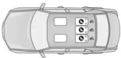
natural_image
Top-down line drawing of a car with four seats and three windows, no text or symbols presentA0503000946US
LATCH Positions For Installing Child Restraints In This Vehicle
Lower Anchorage Symbol (2 Anchorages Per Seating Position)
Top Tether Anchorage Symbol
| Frequently Asked Questions About Installing Child Restraints With LATCH | ||
| What is the weight limit (child's weight + weight of the child restraint) for using the LATCH anchorage system to attach the child restraint? | 65 lbs (29.5 kg) | Use the LATCH anchorage system until the combined weight of the child and the child restraint is 65 lbs (29.5 kg). Use the seat belt and tether anchor instead of the LATCH system once the combined weight is more than 65 lbs (29.5 kg). |
| Can the LATCH anchorages and the seat belt be used together to attach a rear-facing or forward-facing child restraint? | No | Do not use the seat belt when you use the LATCH anchorage system to attach a rear-facing or forward-facing child restraint.Booster seats may be attached to the LATCH anchorages if allowed by the booster seat manufacturer. See your booster seat owner's manual for more information. |
| Can two child restraints be attached using a common lower LATCH anchorage? | No | Never “share” a LATCH anchorage with two or more child restraints. If the center position does not have dedicated LATCH lower anchorages, use the seat belt to install a child seat in the center position next to a child seat using the LATCH anchorages in an outboard position. |
| Can the rear-facing child restraint touch the back of the front passenger seat? | Yes | The child seat may touch the back of the front passenger seat if the child restraint manufacturer also allows contact. See your child restraint owner's manual for more information. |
| Can the rear head restraints be removed? No | ||
Locating The LATCH Anchorages

The lower anchorages are round bars that are found at the rear of the seat cushion where it meets the seatback, below the anchorage symbols on the
seatback. They are just visible when you lean into the rear seat to install the child restraint. You will easily feel them if you run your finger along the gap between the seatback and seat cushion.
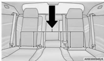
natural_image
Interior view of a car showing seats and a downward arrow indicating a structural change (no text or symbols present)LATCH Anchorages
Locating The Upper Tether Anchorages

There are tether strap anchorages behind each rear seating position located in the panel between the rear seatback and the rear window. They
are found under a plastic cover with the tether anchorage symbol on it.
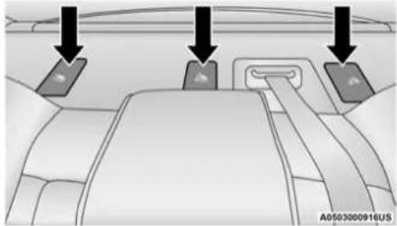
natural_image
Interior view of a car showing dashboard and seatbelt with two directional arrows pointing to the seats (no text or symbols present)Tether Strap Anchorages
LATCH-compatible child restraint systems will be equipped with a rigid bar or a flexible strap on each side. Each will have a hook or connector to attach to the lower anchorage and a way to tighten the connection to the anchorage. Forward-facing child restraints and some rear-facing child restraints will also be equipped with a tether strap. The tether strap will have a hook at the end to attach to the top tether anchorage and a way to tighten the strap after it is attached to the anchorage.
Center Seat LATCH
If a child restraint installed in the center position blocks the seat belt webbing or buckle for the outboard position, do not use that outboard position. If a child seat in the center
position blocks the outboard LATCH anchors or seat belt, do not install a child seat in that outboard position.
WARNING!
Never use the same lower anchorage to attach more than one child restraint. See page 200 for typical installation instructions.
Always follow the directions of the child restraint manufacturer when installing your child restraint. Not all child restraint systems will be installed as described here.
To Install A LATCH-Compatible Child Restraint
If the selected seating position has a Switchable Automatic Locking Retractor (ALR) seat belt, stow the seat belt, following the instructions below. See ➤ page 202 to check what type of seat belt each seating position has.
- Loosen the adjusters on the lower straps and on the tether strap of the child seat so that you can more easily attach the hooks or connectors to the vehicle anchorages.
- Place the child seat between the lower anchorages for that seating position. If the second row seat can be reclined, you may recline the seat and/or raise the head restraint (if adjustable) to get a better fit. If the rear seat can be moved forward and rearward in the vehicle, you may wish to move it to its rear-most position to make room for the child seat. You may also move the front seat forward to allow more room for the child seat.
- Attach the lower hooks or connectors of the child restraint to the lower anchorages in the selected seating position.
-
If the child restraint has a tether strap, connect it to the top tether anchorage. See page 204 for directions to attach a tether anchor.
-
Tighten all of the straps as you push the child restraint rearward and downward into the seat. Remove slack in the straps according to the child restraint manufacturer's instructions.
- Test that the child restraint is installed tightly by pulling back and forth on the child seat at the belt path. It should not move more than 1 inch (25.4 mm) in any direction.
How To Stow An Unused Switchable-ALR (ALR) Seat Belt:
When using the LATCH attaching system to install a child restraint, stow all ALR seat belts that are not being used by other occupants or being used to secure child restraints. An unused belt could injure a child if they play with it and accidentally lock the seat belt retractor. Before installing a child restraint using the LATCH system, buckle the seat belt behind the child restraint and out of the child's reach. If the buckled seat belt interferes with the child restraint installation, instead of buckling it behind the child restraint, route the seat belt through the child restraint belt path and then buckle it. Do not lock the seat belt. Remind all children in the vehicle that the seat belts are not toys and that they should not play with them.
WARNING!
- Improper installation of a child restraint to the LATCH anchorages can lead to failure of the restraint. The child could be badly injured or killed. Follow the child restraint manufacturer's directions exactly when installing an infant or child restraint.
- Child restraint anchorages are designed to withstand only those loads imposed by correctly-fitted child restraints. Under no circumstances are they to be used for adult seat belts, harnesses, or for attaching other items or equipment to the vehicle.
Installing Child Restraints Using The Vehicle Seat Belt
Child restraint systems are designed to be secured in vehicle seats by lap belts or the lap belt portion of a lap/shoulder belt.
WARNING!
- Improper installation or failure to properly secure a child restraint can lead to failure of the restraint. The child could be badly injured or killed.
- Follow the child restraint manufacturer's directions exactly when installing an infant or child restraint.
The seat belts in the passenger seating positions are equipped with a Switchable Automatic Locking Retractor (ALR) that is designed to keep the lap portion of the seat belt tight around the child restraint so that it is not necessary to use a locking clip. The ALR retractor can be "switched" into a locked mode by pulling all of the webbing out of the retractor and then letting the webbing retract back into the retractor. If it is locked, the ALR will make a clicking noise while the webbing is pulled back into the retractor.
See the "Automatic Locking Mode" description page 183 for additional information on ALR.
Please see the table below and the following sections for more information.
Lap/Shoulder Belt Systems For Installing Child Restraints In This Vehicle
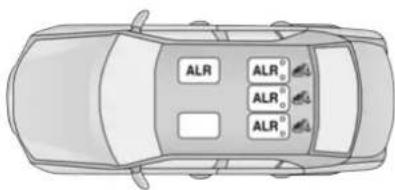
text_image
ALR ALR° ALR° ALR°A0503000945US
Automatic Locking Retractor (ALR) Locations
ALR — Switchable Automatic Locking Retractor Top Tether Anchorage Symbol
| Frequently Asked Questions About Installing Child Restraints With Seat Belts | ||
| What is the weight limit (child's weight + weight of the child restraint) for using the Tether Anchor with the seat belt to attach a forward facing child restraint? | Weight limit of the Child Restraint | Always use the tether anchor when using the seat belt to install a forward facing child restraint, up to the recommended weight limit of the child restraint. |
| Can the rear-facing child restraint touch the back of the front passenger seat? | Yes | Contact between the front passenger seat and the child restraint is allowed, if the child restraint manufacturer also allows contact. |
| Can the rear head restraints be removed? | No | |
| Can the buckle stalk be twisted to tighten the seat belt against the belt path of the child restraint? | No | Do not twist the buckle stalk in a seating position with an ALR retractor. |
Installing A Child Restraint With A Switchable Automatic Locking Retractor (ALR):
Child restraint systems are designed to be secured in vehicle seats by lap belts or the lap belt portion of a lap/shoulder belt.
WARNING!
- Improper installation or failure to properly secure a child restraint can lead to failure of the restraint. The child could be badly injured or killed.
WARNING! (Continued)
- Follow the child restraint manufacturer's directions exactly when installing an infant or child restraint.
(Continued)
204 SAFETY
- Place the child seat in the center of the seating position. If the second row seat can be reclined, you may recline the seat and/or raise the head restraint (if adjustable) to get a better fit. If the rear seat can be moved forward and rearward in the vehicle, you may wish to move it to its rear-most position to make room for the child seat. You may also move the front seat forward to allow more room for the child seat.
- Pull enough of the seat belt webbing from the retractor to pass it through the belt path of the child restraint. Do not twist the belt webbing in the belt path.
- Slide the latch plate into the buckle until you hear a "click."
- Pull on the webbing to make the lap portion tight against the child seat.
-
To lock the seat belt, pull down on the shoulder part of the belt until you have pulled all the seat belt webbing out of the retractor. Then, allow the webbing to retract back into the retractor. As the webbing retracts, you will hear a clicking sound. This means the seat belt is now in the Automatic Locking mode.
-
Try to pull the webbing out of the retractor. If it is locked, you should not be able to pull out any webbing. If the retractor is not locked, repeat step 5.
- Finally, pull up on any excess webbing to tighten the lap portion around the child restraint while you push the child restraint rearward and downward into the vehicle seat.
- If the child restraint has a top tether strap and the seating position has a top tether anchorage, connect the tether strap to the anchorage and tighten the tether strap. See page 204 for directions to attach a tether anchor.
- Test that the child restraint is installed tightly by pulling back and forth on the child seat at the belt path. It should not move more than 1 inch (25.4 mm) in any direction.
Any seat belt system will loosen with time, so check the belt occasionally, and pull it tight if necessary.
Installing Child Restraints Using The Top Tether Anchorage:
WARNING!
Do not attach a tether strap for a rear-facing car seat to any location in front of the car seat, including the seat frame or a tether anchorage. Only attach the tether strap of a rear-facing car seat to the tether anchorage that is approved for that seating position, located behind the top of the vehicle seat. See page 198 for the location of approved tether anchorages in your vehicle.
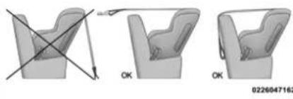
natural_image
Three-step illustration of a car seat assembly with diagonal lines indicating alignment, no text or symbols present.-
Look behind the seating position where you plan to install the child restraint to find the tether anchorage. You may need to move the seat forward to provide better access to the tether anchorage. If there is no top tether anchorage for that seating position, move the child restraint to another position in the vehicle if one is available.
-
Rotate or lift the cover to access the anchor directly behind the seat where you are placing the child restraint.
- Route the tether strap to provide the most direct path for the strap between the anchor and the child seat. If your vehicle is equipped with adjustable rear head restraints, raise the head restraint, and where possible, route the tether strap under the head restraint and between the two posts. If not possible, lower the head restraint and pass the tether strap around the outboard side of the head restraint.
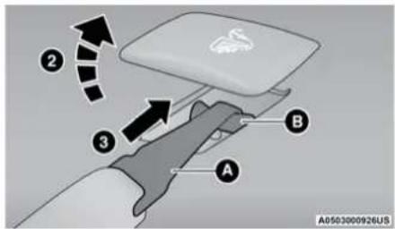
text_image
A0503000926US ② ③ A BTether Strap Mounting
2 - Cover
3 - Attaching Strap
A – Tether Strap Hook
B — Tether Anchor
- Attach the tether strap hook of the child restraint to the top tether anchorage as shown in the diagram.
- Remove slack in the tether strap according to the child restraint manufacturer's instructions.
WARNING!
- An incorrectly anchored tether strap could lead to increased head motion and possible injury to the child. Use only the anchorage position directly behind the child seat to secure a child restraint top tether strap.
- If your vehicle is equipped with a split rear seat, make sure the tether strap does not slip into the opening between the seat-backs as you remove slack in the strap.
Center Tether Attachment
- If adjustable, lower the adjustable center head restraint to the full down position.
- Route the tether strap over the seatback and head restraint.
- Attach the tether strap hook of the child restraint to the center tether anchorage located in the panel between the rear seatback and the rear window.
- Remove slack in the tether strap according to the child restraint manufacturer's instructions.
SAFETY TIPS
TRANSPORTING PASSENGERS
NEVER TRANSPORT PASSENGERS IN THE CARGO AREA.
WARNING!
- Do not leave children or animals inside parked vehicles in hot weather. Interior heat build-up may cause serious injury or death.
- It is extremely dangerous to ride in a cargo area, inside or outside of a vehicle. In a collision, people riding in these areas are more likely to be seriously injured or killed.
- Do not allow people to ride in any area of your vehicle that is not equipped with seats and seat belts.
- Be sure everyone in your vehicle is in a seat and using a seat belt properly.
TRANSPORTING PETS
Air Bags deploying in the front seat could harm your pet. An unrestrained pet will be thrown about and possibly injured, or injure a passenger during panic braking or in a collision.
Pets should be restrained in the rear seat (if equipped) in pet harnesses or pet carriers that are secured by seat belts.
SAFETY CHECKS YOU SHOULD MAKE INSIDE THE VEHICLE
Seat Belts
Inspect the seat belt system periodically, checking for cuts, frays, and loose parts. Damaged parts must be replaced immediately. Do not disassemble or modify the system.
Front seat belt assemblies must be replaced after a collision. Rear seat belt assemblies must be replaced after a collision if they have been damaged (i.e., bent retractor, torn webbing, etc.). If there is any question regarding seat belt or retractor condition, replace the seat belt.
Air Bag Warning Light
The Air Bag Warning Light will turn on for four to eight seconds as a bulb check when the ignition switch is first placed in the ON/RUN position. If the light is either not on during starting, stays on, or turns on while driving, have the system inspected at an authorized dealer as soon as possible. After the bulb check, this light will illuminate with a single chime when a fault
with the Air Bag System has been detected. It will stay on until the fault is removed. If the light comes on intermittently or remains on while driving, have an authorized dealer service the vehicle immediately ↘ page 176.
Defroster
Check operation by selecting the defrost mode and place the blower control on high speed. You should be able to feel the air directed against the windshield. See an authorized dealer for service if your defroster is inoperable.
Floor Mat Safety Information
Always use floor mats designed to fit your vehicle. Only use a floor mat that does not interfere with the operation of the accelerator, brake or clutch pedals. Only use a floor mat that is securely attached using the floor mat fasteners so it cannot slip out of position and interfere with the accelerator, brake or clutch pedals or impair safe operation of your vehicle in other ways.
WARNING!
An improperly attached, damaged, folded, or stacked floor mat, or damaged floor mat fasteners may cause your floor mat to interfere with the accelerator, brake, or clutch pedals and cause a loss of vehicle control. To prevent SERIOUS INJURY or DEATH:
- ALWAYS securely attach your floor mat using the floor mat fasteners. DO NOT install your floor mat upside down or turn your floor mat over. Lightly pull to confirm mat is secured using the floor mat fasteners on a regular basis.
- ALWAYS REMOVE THE EXISTING FLOOR MAT FROM THE VEHICLE before installing any other floor mat. NEVER install or stack an additional floor mat on top of an existing floor mat.
(Continued)
WARNING! (Continued)
- ONLY install floor mats designed to fit your vehicle. NEVER install a floor mat that cannot be properly attached and secured to your vehicle. If a floor mat needs to be replaced, only use a FCA approved floor mat for the specific make, model, and year of your vehicle.
- ONLY use the driver's side floor mat on the driver's side floor area. To check for interference, with the vehicle properly parked with the engine off, fully depress the accelerator, the brake, and the clutch pedal (if present) to check for interference. If your floor mat interferes with the operation of any pedal, or is not secure to the floor, remove the floor mat from the vehicle and place the floor mat in your trunk.
(Continued)
WARNING! (Continued)
- ONLY use the passenger's side floor mat on the passenger's side floor area.
- ALWAYS make sure objects cannot fall or slide into the driver's side floor area when the vehicle is moving. Objects can become trapped under accelerator, brake, or clutch pedals and could cause a loss of vehicle control.
- NEVER place any objects under the floor mat (e.g., towels, keys, etc.). These objects could change the position of the floor mat and may cause interference with the accelerator, brake, or clutch pedals.
- If the vehicle carpet has been removed and re-installed, always properly attach carpet to the floor and check the floor mat fasteners are secure to the vehicle carpet. Fully depress each pedal to check for interference with the accelerator, brake, or clutch pedals then re-install the floor mats.
(Continued)
WARNING! (Continued)
- It is recommended to only use mild soap and water to clean your floor mats. After cleaning, always check your floor mat has been properly installed and is secured to your vehicle using the floor mat fasteners by lightly pulling mat.
PERIODIC SAFETY CHECKS YOU SHOULD MAKE OUTSIDE THE VEHICLE
Tires
Examine tires for excessive tread wear and uneven wear patterns. Check for stones, nails, glass, or other objects lodged in the tread or sidewall. Inspect the tread for cuts and cracks. Inspect sidewalls for cuts, cracks, and bulges. Check the lug nuts/bolt torque for tightness. Check the tires (including spare) for proper cold inflation pressure.
Have someone observe the operation of brake lights and exterior lights while you work the controls. Check turn signal and high beam indicator lights on the instrument panel.
Door Latches
Check for proper closing, latching, and locking.
Fluid Leaks
Check area under the vehicle after overnight parking for fuel, coolant, oil, or other fluid leaks. Also, if gasoline fumes are detected or if fuel or brake fluid leaks are suspected, the cause should be located and corrected immediately.
EXHAUST GAS
WARNING!
Exhaust gases can injure or kill. They contain carbon monoxide (CO), which is colorless and odorless. Breathing it can make you unconscious and can eventually poison you. To avoid breathing (CO), follow these safety tips:
- Do not run the engine in a closed garage or in confined areas any longer than needed to move your vehicle in or out of the area.
- If you are required to drive with the trunk/liftgate/rear doors open, make sure that all windows are closed and the climate control BLOWER switch is set at high speed. DO NOT use the recirculation mode.
- If it is necessary to sit in a parked vehicle with the engine running, adjust your heating or cooling controls to force outside air into the vehicle. Set the blower at high speed.
The best protection against carbon monoxide entry into the vehicle body is a properly maintained engine exhaust system.
Whenever a change is noticed in the sound of the exhaust system, when exhaust fumes can be detected inside the vehicle, or when the underside or rear of the vehicle is damaged, have an authorized dealer inspect the complete exhaust system and adjacent body areas for broken, damaged, deteriorated, or mispositioned parts. Open seams or loose connections could permit exhaust fumes to seep into the passenger compartment. In addition, inspect the exhaust system each time the vehicle is raised for lubrication or oil change. Replace as required.
CARBON MONOXIDE WARNINGS
WARNING!
Carbon monoxide (CO) in exhaust gases is deadly. Follow the precautions below to prevent carbon monoxide poisoning:
- Do not inhale exhaust gases. They contain carbon monoxide, a colorless and odorless gas, which can kill. Never run the engine in a closed area, such as a garage, and never sit in a parked vehicle with the engine running for an extended period. If the vehicle is stopped in an open area with the engine running for more than a short period, adjust the ventilation system to force fresh, outside air into the vehicle.
- Guard against carbon monoxide with proper maintenance. Have the exhaust system inspected every time the vehicle is raised. Have any abnormal conditions repaired promptly. Until repaired, drive with all side windows fully open.
IN CASE OF EMERGENCY
HAZARD WARNING FLASHERS
The Hazard Warning Flashers switch is located on the switch bank just above the climate controls.
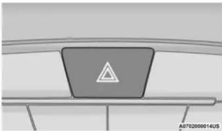
natural_image
Diagram of a device with a triangular symbol on top, mounted on a base (no text or labels)Hazard Warning Flashers Switch
Push the switch to turn on the Hazard Warning Flashers. When the switch is activated, all directional turn signals will flash on and off to warn oncoming traffic of an emergency. Push the switch a second time to turn off the Hazard Warning Flashers.
This is an emergency warning system and it should not be used when the vehicle is in motion. Use it when your vehicle is disabled and it is creating a safety hazard for other motorists.
When you must leave the vehicle to seek assistance, the Hazard Warning Flashers will continue to operate even though the ignition is placed in the OFF position.
NOTE:
With extended use, the Hazard Warning Flashers may discharge the battery.
ASSIST AND SOS MIRROR — IF EQUIPPED
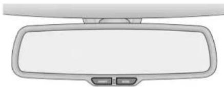
natural_image
Top-down view of a car rearview mirror with two buttons at the front (no text or symbols)A0703000043US
Assist And SOS Mirror
If equipped, the rearview mirror contains an ASSIST and a SOS button.
WARNING!
ALWAYS obey traffic laws and pay attention to the road. ALWAYS drive safely with your hands on the steering wheel. You have full responsibility and assume all risks related to the use of the Uconnect and SiriusXM Guardian™ features and applications in this vehicle. Only use Uconnect features and SiriusXM Guardian™ services when it is safe to do so. Failure to do so may result in an accident involving serious injury or death.
NOTE:
- Your vehicle may be transmitting data as authorized by the subscriber ↩ page 298.
- The SOS and ASSIST buttons will only function if you are connected to an operable LTE (voice/data) or 4G (data) network. Other Uconnect services will only be operable if
your SiriusXM Guardian™ service is active and you are connected to an operable LTE (voice/data) or 4G (data) network.
ASSIST Call
The ASSIST Button is used to automatically connect you to any one of the following support centers:
- Roadside Assistance – If you get a flat tire, or need a tow, just push the ASSIST button and you will be connected to a representative for assistance. Roadside Assistance will know what vehicle you're driving and its location. Additional fees may apply for roadside Assistance.
- SiriusXM Guardian™ Customer Care – In-vehicle support for SiriusXM Guardian™.
- Vehicle Customer Care – Total support for all other vehicle issues.
SOS Call
- Push the SOS Call button on the Rearview Mirror.
NOTE:
In case the SOS Call button is pushed in error, there will be a 10 second delay before the SOS Call system initiates a call to a SOS operator. To cancel the SOS Call connection, push the SOS call button on the Rearview Mirror or press the cancellation button on the Device Screen. Termination of the SOS Call will turn off the green LED light on the Rearview Mirror.
- The LED light located between the ASSIST and SOS buttons on the Rearview Mirror will turn green once a connection to a SOS operator has been made.
-
Once a connection between the vehicle and a SOS operator is made, the SOS Call system may transmit the following important vehicle information to a SOS operator:
-
Indication that the occupant placed a SOS Call.
- The vehicle brand.
-
The last known GPS coordinates of the vehicle.
-
You should be able to speak with the SOS operator through the vehicle audio system to determine if additional help is needed.
WARNING!
ALWAYS obey traffic laws and pay attention to the road. ALWAYS drive safely with your hands on the steering wheel. You have full responsibility and assume all risks related to the use of the Uconnect and SiriusXM Guardian™ features and applications in this vehicle. Only use Uconnect features and SiriusXM Guardian™ services when it is safe to do so. Failure to do so may result in an accident involving serious injury or death.
NOTE:
- Your vehicle may be transmitting data as authorized by the subscriber.
- Once a connection is made between the vehicle's SOS Call system and the SOS operator, the SOS operator may be able to open a voice connection with the vehicle to determine if additional help is needed. Once the SOS operator opens a voice connection with the vehicle's SOS Call system, the operator
212 IN CASE OF EMERGENCY
should be able to speak with you or other vehicle occupants and hear sounds occurring in the vehicle. The vehicle's SOS Call system will attempt to remain connected with the SOS operator until the SOS operator terminates the connection.
- The SOS operator may attempt to contact appropriate emergency responders and provide them with important vehicle information and GPS coordinates.
WARNING!
- If anyone in the vehicle could be in danger (e.g., fire or smoke is visible, dangerous road conditions or location), do not wait for voice contact from an Emergency Services Agent. All occupants should exit the vehicle immediately and move to a safe location.
- Never place anything on or near the vehicle's operable network and GPS antennas. You could prevent operable network and GPS signal reception, which can prevent your vehicle from placing an emergency call. An operable network and GPS signal reception is required for the SOS Call system to function properly.
(Continued)
WARNING! (Continued)
- The SOS Call system is embedded into the vehicle's electrical system. Do not add aftermarket electrical equipment to the vehicle's electrical system. This may prevent your vehicle from sending a signal to initiate an emergency call. To avoid interference that can cause the SOS Call system to fail, never add aftermarket equipment (e.g., two-way mobile radio, CB radio, data recorder, etc.) to your vehicle's electrical system or modify the antennas on your vehicle. IF YOUR VEHICLE LOSES BATTERY POWER FOR ANY REASON (INCLUDING DURING OR AFTER AN ACCIDENT), THE UCONNECT FEATURES, APPS AND SERVICES, AMONG OTHERS, WILL NOT OPERATE.
- Modifications to any part of the SOS Call system could cause the air bag system to fail when you need it. You could be injured if the air bag system is not there to help protect you.
SOS Call System Limitations
Vehicles sold in Mexico DO NOT have SOS Call system capabilities.
SOS or other emergency line operators in Mexico may not answer or respond to SOS system calls.
If the SOS Call system detects a malfunction, any of the following may occur at the time the malfunction is detected, and at the beginning of each ignition cycle:
- The Rearview Mirror light located between the ASSIST and SOS buttons will continuously illuminate red.
- The Device Screen will display the following message "Vehicle device requires service. Please contact an authorized dealer".
- An In-Vehicle Audio message will state "Vehicle device requires service. Please contact an authorized dealer".
WARNING!
- Ignoring the Rearview Mirror light could mean you will not have SOS Call services. If the Rearview Mirror light is illuminated, have an authorized dealer service the SOS Call system immediately.
- The Occupant Restraint Control module turns on the air bag Warning Light on the instrument panel if a malfunction in any part of the system is detected. If the Air Bag Warning Light is illuminated, have an authorized dealer service the Occupant Restraint Control system immediately.
Even if the SOS Call system is fully functional, factors beyond FCA US LLC's control may prevent or stop the SOS Call system operation. These include, but are not limited to, the following factors:
- The ignition is in the OFF position.
- The vehicle's electrical systems are not intact.
-
The SOS Call system software and/or hardware are damaged during a crash.
-
The vehicle battery loses power or becomes disconnected during a vehicle crash.
- LTE (voice/data) or 4G (data) network and/or Global Positioning Satellite signals are unavailable or obstructed.
- Equipment malfunction at the SOS operator facility.
- Operator error by the SOS operator.
- LTE (voice/data) or 4G (data) network congestion.
- Weather.
- Buildings, structures, geographic terrain, or tunnels.
WARNING!
ALWAYS obey traffic laws and pay attention to the road. ALWAYS drive safely with your hands on the steering wheel. You have full responsibility and assume all risks related to the use of the Uconnect and SiriusXM Guardian™ features and applications in this vehicle. Only use Uconnect features and SiriusXM Guardian™ services when it is safe to do so. Failure to do so may result in an accident involving serious injury or death.
NOTE:
- Your vehicle may be transmitting data as authorized by the subscriber.
- Never place anything on or near the vehicle's LTE (voice/data) or 4G (data) and GPS antennas. You could prevent LTE (voice/data) or 4G (data) and GPS signal reception, which can prevent your vehicle from placing an emergency call. An operable LTE (voice/data) or 4G (data) network connection and a GPS signal is required for the SOS Call system to function properly.
- Changes or modifications not expressly approved by the party responsible for compliance could void the user's authority to operate the equipment.
CAUTION!
To avoid damage to the mirror during cleaning, never spray any cleaning solution directly onto the mirror. Apply the solution onto a clean cloth and wipe the mirror clean.
JACKING AND TIRE CHANGING
WARNING!
- Do not attempt to change a tire on the side of the vehicle close to moving traffic. Pull far enough off the road to avoid the danger of being hit when operating the jack or changing the wheel.
- Being under a jacked-up vehicle is dangerous. The vehicle could slip off the jack and fall on you. You could be crushed. Never put any part of your body under a vehicle that is on a jack. If you need to get under a raised vehicle, take it to a service center where it can be raised on a lift.
- Never start or run the engine while the vehicle is on a jack.
- The jack is designed to be used as a tool for changing tires only. The jack should not be used to lift the vehicle for service purposes. The vehicle should be jacked on a firm level surface only. Avoid ice or slippery areas.
PREPARATIONS FOR JACKING
- Park the vehicle on a firm, level surface. Avoid ice or slippery areas.
WARNING!
Do not attempt to change a tire on the side of the vehicle close to moving traffic. Pull far enough off the road to avoid being hit when operating the jack or changing the wheel.
- Turn on the Hazard Warning Flashers.
- Apply the parking brake.
- Place the gear selector into PARK (P).
- Turn the ignition to the OFF position.
- Block both the front and rear of the wheel diagonally opposite the jacking position. For example, if the driver's front wheel is being changed, block the passenger's rear wheel.
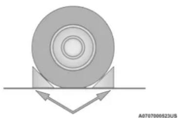
natural_image
Diagram of a mechanical component with circular and rectangular features, showing directional arrows (no text or symbols)Wheel Blocked
NOTE:
Passengers should not remain in the vehicle when the vehicle is being lifted or raised.
JACK LOCATION/SPARE TIRE STOWAGE
The jack and spare tire are both stowed under an access cover in the trunk. Follow these steps to access the jack and spare tire.
NOTE:
The spare tire must be removed in order to access the jack.
- Open the trunk.
-
Lift the access cover using the pull strap.
-
Rotate the fastener securing the spare tire counterclockwise to remove it.
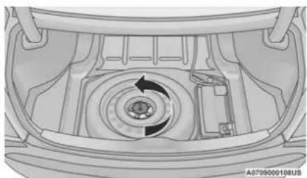
natural_image
Top-down view of a car engine bay with internal components and a circular arrow indicating rotation (no text or symbols)Spare Tire Fastener
- Remove the spare tire.
- Rotate the fastener securing the jack counterclockwise to remove it.
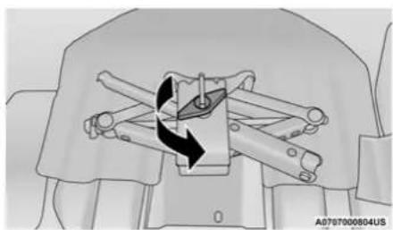
natural_image
Mechanical assembly diagram showing a rotating component with arrows indicating motion (no text or symbols)Jack Fastener
- Remove the jack and lug wrench assembly from under the spare tire. Turn the jack screw to the left to loosen the lug wrench, and remove the wrench from the jack assembly.
WARNING!
A loose tire or jack thrown forward in a collision or hard stop could endanger the occupants of the vehicle. Always stow the jack parts and the spare tire in the places provided. Have the deflated (flat) tire repaired or replaced immediately.
JACKING AND CHANGING A TIRE
WARNING!
Carefully follow these tire changing warnings to help prevent personal injury or damage to your vehicle:
- Always park on a firm, level surface as far from the edge of the roadway as possible before raising the vehicle.
- Turn on the Hazard Warning Flashers.
(Continued)
WARNING! (Continued)
- Apply the parking brake firmly and set an automatic transmission in PARK.
- Chock the wheel diagonally opposite the wheel to be raised.
- Never start or run the engine with the vehicle on a jack.
- Do not let anyone sit in the vehicle when it is on a jack.
- Do not get under the vehicle when it is on a jack. If you need to get under a raised vehicle, take it to a service center where it can be raised on a lift.
- Only use the jack in the positions indicated for lifting this vehicle during a tire change.
- If working on or near a roadway, be extremely careful of motor traffic.
- To assure that spare tires, flat or inflated, are securely stowed, spares must be stowed with the valve stem facing the ground.
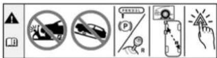
text_image
Safety warning icons with Chinese labels, including no protection symbols, a parking sign, a hand pointing to a warning symbol.060600714
Jacking Warning Label
Placement for the front and rear jacking locations are critical. See the following images for proper jacking locations.
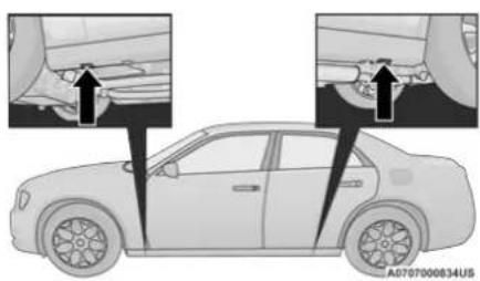
text_image
Diagram showing car side view with labeled parts and arrows indicating damage or repair pointsJacking Locations
CAUTION!
Do not attempt to raise the vehicle by jacking on locations other than those indicated in the Jacking Instructions for this vehicle.
- Remove the spare tire, jack, and lug wrench.
- If equipped with aluminum wheels where the center cap covers the lug nuts, use the lug wrench to pry the center cap off carefully before raising the vehicle.
- Before raising the vehicle, use the lug wrench to loosen, but not remove, the lug nuts on the wheel with the flat tire. Turn the lug nuts counterclockwise one turn while the wheel is still on the ground.
- Place the jack underneath the lift area that is closest to the flat tire. Turn the jack screw clockwise to firmly engage the jack saddle with the lift area of the sill flange.
NOTE:
If the vehicle is too low for jack placement, slide the jack on its side and rotate it up into position.
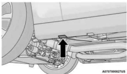
natural_image
Mechanical assembly diagram showing a car wheel connected to a bracket with an arrow indicating a component (no text or symbols present)Front Lifting Point
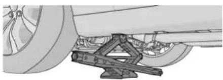
natural_image
Mechanical assembly diagram showing a vehicle under load with a triangular frame and wheel (no text or symbols)A0707000830US
Front Jacking Location

natural_image
Mechanical assembly diagram showing a car wheel connected to a shaft with a valve, no text or symbols presentA070700082BUS
Rear Lifting Point
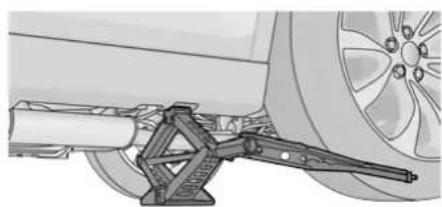
natural_image
Mechanical assembly diagram showing a bracketed clamp and wheel (no text or symbols)A0707000829US
Rear Jacking Location
5. Raise the vehicle just enough to remove the flat tire and install the spare tire.
WARNING!
Raising the vehicle higher than necessary can make the vehicle less stable. It could slip off the jack and hurt someone near it. Raise the vehicle only enough to remove the tire.
-
Remove the lug nuts and tire.
-
Mount the spare tire.
CAUTION!
Be sure to mount the spare tire with the valve stem facing outward. The vehicle could be damaged if the spare tire is mounted incorrectly.
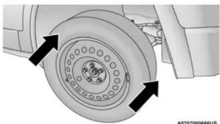
natural_image
Technical diagram of a mechanical component with concentric rings and mounting holes, showing directional arrows (no text or symbols)Mounting Spare Tire
NOTE:
- For vehicles so equipped, do not attempt to install a center cap or wheel cover on the compact spare → page 276.
- Install the lug nuts with the cone shaped end of the lug nut toward the wheel. Lightly tighten the lug nuts.
WARNING!
To avoid the risk of forcing the vehicle off the jack, do not tighten the wheel nuts fully until the vehicle has been lowered. Failure to follow this warning may result in serious injury.
-
Lower the vehicle to the ground by turning the jack handle counterclockwise.
-
Finish tightening the wheel bolts. Push down on the wrench while at the end of the handle for increased leverage. Tighten the wheel bolts in a star pattern until each wheel bolt has been tightened twice. If in doubt about the correct tightness, have them checked with a torque wrench by an authorized dealer or at a service station page 287.
218 IN CASE OF EMERGENCY
- Stow the jack, tools and flat tire. Make sure the base of the jack faces the front of the vehicle before tightening down the fastener.
WARNING!
A loose tire or jack thrown forward in a collision or hard stop could endanger the occupants of the vehicle. Always stow the jack parts and the spare tire in the places provided. Have the deflated (flat) tire repaired or replaced immediately.
JUMP STARTING
If your vehicle has a discharged battery, it can be jump started using a set of jumper cables and a battery in another vehicle, or by using a portable battery booster pack. Jump starting can be dangerous if done improperly, so please follow the procedures in this section carefully.
WARNING!
Do not attempt jump starting if the battery is frozen. It could rupture or explode and cause personal injury.
CAUTION!
Do not use a portable battery booster pack or any other booster source with a system voltage greater than 12 Volts or damage to the battery, starter motor, alternator or electrical system may occur.
NOTE:
When using a portable battery booster pack, follow the manufacturer's operating instructions and precautions.
PREPARATIONS FOR JUMP START
The battery is stored under an access cover in the trunk. Remote battery posts are located on the right side of the engine compartment for jump starting.
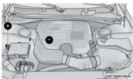
text_image
Technical diagram of a car engine bay with labeled components and a vehicle identifier A0710000138USJump Starting Locations
Remote Positive (+) Post
Remote Negative (-) Post
NOTE:
The remote battery posts are viewed by standing on the right side of the vehicle looking over the fender. The positive battery post may be covered with a protective cap. Lift up on the cap to gain access to the positive battery post.
Do not jump off fuses. Only jump directly off positive post which has a positive (+) symbol on or around the post.
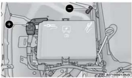
natural_image
Technical diagram of a vehicle engine compartment with labeled ports and wiring (no readable text or symbols)Jump Starting Posts
Remote Positive (+) Post Remote Negative (-) Post
See below steps to prepare for jump starting:
-
Apply the parking brake, shift the automatic transmission into PARK and cycle the ignition to OFF.
-
Turn off the heater, radio, and all electrical accessories.
-
If using another vehicle to jump start the battery, park the vehicle within the jumper cables reach, set the parking brake, and make sure the ignition is OFF.
WARNING!
Do not allow vehicles to touch each other as this could establish a ground connection and personal injury could result.
WARNING!
- Take care to avoid the radiator cooling fan whenever the hood is raised. It can start anytime the ignition switch is ON. You can be injured by moving fan blades.
- Remove any metal jewelry such as rings, watch bands and bracelets that could make an inadvertent electrical contact. You could be seriously injured.
- Batteries contain sulfuric acid that can burn your skin or eyes and generate hydrogen gas which is flammable and explosive. Keep open flames or sparks away from the battery.
Failure to follow this jump starting procedure could result in personal injury or property damage due to battery explosion.
CAUTION!
Failure to follow these procedures could result in damage to the charging system of the booster vehicle or the discharged vehicle.
NOTE:
Make sure at all times that unused ends of jumper cables are not contacting each other or either vehicle while making connections.
Connecting The Jumper Cables
- Connect the positive (+) end of the jumper cable to the remote positive (+) post of the discharged vehicle.
- Connect the opposite end of the positive (+) jumper cable to the positive (+) post of the booster battery.
220 IN CASE OF EMERGENCY
- Connect the negative end (-) of the jumper cable to the negative (-) post of the booster battery.
- Connect the opposite end of the negative (-) jumper cable to the remote negative (-) post (exposed metallic/unpainted post of the discharge vehicle) located directly behind the under-hood fuse box.
WARNING!
Do not connect the jumper cable to the negative (-) post of the discharged battery. The resulting electrical spark could cause the battery to explode and could result in personal injury.
5. Start the engine in the vehicle that has the booster battery, let the engine idle a few minutes, and then start the engine in the vehicle with the discharged battery.
CAUTION!
Do not run the booster vehicle engine above 2,000 rpm since it provides no charging benefit, wastes fuel, and can damage booster vehicle engine.
- Once the engine is started, follow the disconnection procedure below.
Disconnecting The Jumper Cables
- Disconnect the negative (-) end of the jumper cable from the remote negative (-) post of the discharged vehicle.
- Disconnect the opposite end of the negative (-) jumper cable from the negative (-) post of the booster battery.
-
Disconnect the positive (+) end of the jumper cable from the positive (+) post of the booster battery.
-
Disconnect the opposite end of the positive (+) jumper cable from the remote positive (+) post of the discharged vehicle.
- Reinstall the protective cover over the remote positive (+) post of the discharged vehicle.
If frequent jump starting is required to start your vehicle you should have the battery and charging system tested at an authorized dealer.
CAUTION!
Accessories plugged into the vehicle power outlets draw power from the vehicle's battery, even when not in use (i.e., cellular devices, etc.). Eventually, if plugged in long enough without engine operation, the vehicle's battery will discharge sufficiently to degrade battery life and/or prevent the engine from starting.
REFUELING IN AN EMERGENCY – IF EQUIPPED
The vehicle is equipped with a refueling funnel for a Cap-Less Fuel System. If refueling is necessary, while using an approved gas can, please insert the refueling funnel into the filler neck opening.
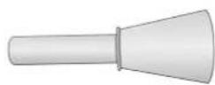
Refueling Funnel
A0711000008US
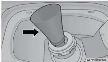
natural_image
Mechanical gear shift lever component with arrow indicating direction (no text or symbols)Inserting Funnel
CAUTION!
To avoid fuel spillage and overfilling, do not "top off" the fuel tank after filling.
Emergency Gas Can Refueling
Most gas cans will not open the flapper doors.
A funnel is provided to allow emergency refueling with a gas can.
See below steps for refueling
- Retrieve funnel from the spare tire storage area.
-
Insert funnel into same filler pipe opening as the fuel nozzle.
-
Ensure funnel is inserted fully to hold flapper doors open.
- Pour fuel into funnel opening.
- Remove funnel from filler pipe, clean off prior to putting back in the spare tire storage area.
WARNING!
- Never have any smoking materials lit in or near the vehicle when the fuel door is open or the tank is being filled.
- Never add fuel when the engine is running. This is in violation of most state and federal fire regulations and may cause the "Malfunction Indicator Light" to turn on.
- A fire may result if fuel is pumped into a portable container that is inside of a vehicle. You could be burned. Always place fuel containers on the ground while filling.
IF YOUR ENGINE OVERHEATS
If the vehicle is overheating, it will need to be serviced by an authorized dealer.
In any of the following situations, you can reduce the potential for overheating by taking the appropriate action.
- On the highways – slow down.
- In city traffic — while stopped, place the transmission in NEUTRAL, but do not increase the engine idle speed while preventing vehicle motion with the brakes.
NOTE:
There are steps that you can take to slow down an impending overheat condition:
- If your Air Conditioner (A/C) is on, turn it off. The A/C system adds heat to the engine cooling system and turning the A/C off can help remove this heat.
- You can also turn the temperature control to maximum heat, the mode control to floor and the blower control to high. This allows the heater core to act as a supplement to the radiator and aids in removing heat from the engine cooling system.
WARNING!
You or others can be badly burned by hot engine coolant (antifreeze) or steam from your radiator. If you see or hear steam coming from under the hood, do not open the hood until the radiator has had time to cool. Never try to open a cooling system pressure cap when the radiator or coolant bottle is hot.
CAUTION!
Driving with a hot cooling system could damage your vehicle. If the temperature gauge reads HOT (H), pull over and stop the vehicle. Idle the vehicle with the air conditioner turned off until the pointer drops back into the normal range. If the pointer remains on HOT (H), and you hear continuous chimes, turn the engine off immediately and call for service.
MANUAL PARK RELEASE
WARNING!
Always secure your vehicle by fully applying the parking brake before activating the Manual Park Release. In addition, you should be seated in the driver's seat with your foot firmly on the brake pedal when activating the Manual Park Release. Activating the Manual Park Release will allow your vehicle to roll away if it is not secured by the parking brake, or by proper connection to a tow vehicle. Activating the Manual Park Release on an unsecured vehicle could lead to serious injury or death for those in or around the vehicle.
To move the vehicle in cases where the transmission will not shift out of PARK (such as a depleted battery), a Manual Park Release is available.
Follow these steps to use the Manual Park Release:
- Firmly apply the parking brake.
- Remove the console storage bin to access the Manual Park Release lever.
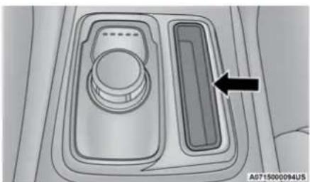
natural_image
Diagram of a car intake tray with a control panel and a highlighted rectangular component (no text or symbols)Manual Park Release Cover
- Using a small screwdriver or similar tool, fish the tether strap up through the opening in the console base.
- Press and maintain firm pressure on the brake pedal.
- Insert the screwdriver into the slot in the center of the lever, and disengage the lever locking tab by pushing it to the right.
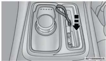
natural_image
Diagram of a car intake tray with a cable and directional arrow indicating flow or movement (no text or symbols)Engaging The Lever
- While holding the locking tab in the disengaged position, pull the tether strap to rotate the lever up and rearward, until it locks in place in the vertical position. The vehicle is now out of PARK and can be moved. Release the parking brake only when the vehicle is securely connected to a tow vehicle.
To Reset The Manual Park Release:
- Push the latch (at the base of the lever, on the rear side) rearward (away from the lever) to unlatch the lever.
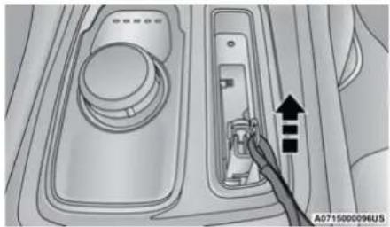
natural_image
Interior view of a car dashboard with a hand pointing to a control panel (no text or symbols visible)Disengaging The Lever
- Rotate the Manual Park Release lever forward and down, to its original position, until the locking tab snaps into place to secure the lever.
- Pull up gently on the tether strap to confirm that the lever is locked in its stowed position.
- Tuck the tether strap into the base of the console. Reinstall the console storage bin.
When the lever is in the release position the access cover cannot be reinstalled.
FREEING A STUCK VEHICLE
If your vehicle becomes stuck in mud, sand, or snow, it can often be moved using a rocking motion. Turn the steering wheel right and left to clear the area around the front wheels. Then, shift back and forth between DRIVE and REVERSE while gently pressing the accelerator. Use the least amount of accelerator pedal pressure that will maintain the rocking motion, without spinning the wheels or racing the engine.
CAUTION!
Racing the engine or spinning the wheels may lead to transmission overheating and failure. Allow the engine to idle with the transmission in NEUTRAL for at least one minute after every five rocking-motion cycles. This will minimize overheating and reduce the risk of clutch or transmission failure during prolonged efforts to free a stuck vehicle.
NOTE:
- For vehicles with automatic transmission: Shifts between DRIVE and REVERSE can only be achieved at wheel speeds of 5 mph (8 km/h) or less. Whenever the transmission remains in NEUTRAL for more than two seconds, you must press the brake pedal to engage DRIVE or REVERSE.
- Push the ESC OFF switch to place the Electronic Stability Control (ESC) system in "Partial OFF" mode, before rocking the vehicle → page 161. Once the vehicle has been freed, push the ESC OFF switch again to restore "ESC On" mode.
WARNING!
Fast spinning tires can be dangerous. Forces generated by excessive wheel speeds may cause damage, or even failure, of the axle and tires. A tire could explode and injure someone. Do not spin your vehicle's wheels faster than 30 mph (48 km/h) or for longer than 30 seconds continuously without stopping when you are stuck and do not let anyone near a spinning wheel, no matter what the speed.
CAUTION!
- Racing the engine or spinning the wheels may lead to transmission overheating and failure. Allow the engine to idle with the transmission in NEUTRAL for at least one minute after every five rocking-motion cycles. This will minimize overheating and reduce the risk of transmission failure during prolonged efforts to free a stuck vehicle.
- When "rocking" a stuck vehicle by shifting between DRIVE and REVERSE, do not spin the wheels faster than 15 mph (24 km/h), or drivetrain damage may result.
- Revving the engine or spinning the wheels too fast may lead to transmission overheating and failure. It can also damage the tires. Do not spin the wheels above 30 mph (48 km/h) while in gear (no transmission shifting occurring).
TOWING A DISABLED VEHICLE
This section describes procedures for towing a disabled vehicle using a commercial towing service.
| Towing Condition Wheels OFF The Ground RWD MODELS AWD MODELS | |||
| Flat Tow NONE | If transmission is operable:• Transmission in NEUTRAL• 30 mph (48 km/h) max speed• 30 miles (48 km) max distance | NOT ALLOWED | |
| Wheel Lift Or Dolly Tow | Front | NOT RECOMMENDED (but, if used,same limitations as above) | NOT ALLOWED |
| Rear NOT RECOMMENDED | NOT RECOMMENDED, but, if used:• Ignition in ON/RUN mode• Transmission in NEUTRAL (NOTin PARK) | ||
| Flatbed ALL BEST METHOD BEST METHOD | |||
Proper towing or lifting equipment is required to prevent damage to your vehicle. Use only tow bars and other equipment designed for this purpose, following equipment manufacturer's instructions. Use of safety chains is mandatory. Attach a tow bar or other towing device to main structural members of the vehicle, not to bumpers or associated brackets. State and local laws regarding vehicles under tow must be observed.
If you must use the accessories (wipers, defrosters, etc.) while being towed, the ignition must be in the ON/RUN mode, not the ACC mode.
If the key fob is unavailable, or the vehicle's battery is discharged, instructions on shifting the transmission out of PARK for towing page 222.
CAUTION!
- Do not use sling type equipment when towing. Vehicle damage may occur.
(Continued)
CAUTION! (Continued)
- When securing the vehicle to a flat bed truck, do not attach to front or rear suspension components. Damage to your vehicle may result from improper towing.
- FCA US LLC does not recommend towing this vehicle using a tow dolly. Vehicle damage may occur.
ALL WHEEL DRIVE (AWD) MODELS
FCA US LLC recommends towing your vehicle with all four wheels OFF the ground using a flatbed.
If the transmission and driveline are operable, AWD models can also be towed with the ignition in the ON/RUN mode, the transmission in NEUTRAL (N) (not in PARK!), and the rear wheels OFF the ground with no limitation on speed or distance. Since the ignition MUST be in the ON/RUN mode to tow in this manner, AWD vehicles must be towed with ALL FOUR wheels OFF the ground (e.g. on a flatbed truck) if the key fob is unavailable.
CAUTION!
- Towing this vehicle using any other method can cause severe transmission and/or transfer case damage.
- Damage from improper towing is not covered under the New Vehicle Limited Warranty.
REAR WHEEL DRIVE (RWD) MODELS
FCA LLC US recommends towing your vehicle with all four wheels OFF the ground using a flatbed.
If flatbed equipment is not available, and the transmission is operable, this vehicle may be flat towed (with all four wheels on the ground) under the following conditions:
- The transmission must be in NEUTRAL (N). Instructions on shifting the transmission to NEUTRAL (N) when the engine is off page 222.
- The towing speed must not exceed 30 mph (48 km/h).
- The towing distance must not exceed 30 miles (48 km).
If the transmission is not operable, or the vehicle must be towed faster than 30 mph (48 km/h) or farther than 30 miles (48 km), then the only acceptable method of towing is with a flatbed truck.
CAUTION!
Towing this vehicle in violation of the above requirements can cause severe transmission damage. Damage from improper towing is not covered under the New Vehicle Limited Warranty.
ENHANCED ACCIDENT RESPONSE SYSTEM (EARS)
This vehicle is equipped with an Enhanced Accident Response System.
This feature is a communication network that takes effect in the event of an impact ➔ page 191.
This vehicle is equipped with an event data recorder (EDR). The main purpose of an EDR is to record data that will assist in understanding how a vehicle's systems performed under certain crash or near crash-like situations, such as an air bag deployment or hitting a road obstacle ➔ page 193.
SERVICING AND MAINTENANCE
SCHEDULED SERVICING
This vehicle is equipped with an automatic oil change indicator system. The oil change indicator system will remind you that it is time to take your vehicle in for scheduled maintenance.
Based on engine operation conditions, the oil change indicator message will illuminate. This means that service is required for the vehicle. Operating conditions such as frequent short-trips, trailer tow, and extremely hot or cold ambient temperatures will influence when the "Change Oil" or "Oil Change Required" message is displayed. Have your vehicle serviced as soon as possible, within the next 500 miles (805 km).
The “Oil Change Required” message will be displayed in the instrument cluster and a single chime will sound, indicating that an oil change is necessary.
An authorized dealer will reset the oil change indicator message after completing the scheduled oil change.
NOTE:
Under no circumstances should oil change intervals exceed 10,000 miles (16,000 km), 12 months or 350 hours of engine run time, whichever comes first. The 350 hours of engine run or idle time is generally only a concern for fleet customers.
Once A Month Or Before A Long Trip:
- Check engine oil level.
- Check windshield washer fluid level.
- Check tire pressure and look for unusual wear or damage. Rotate tires at the first sign of irregular wear, even if it occurs before your next scheduled service.
- Check the fluid levels of the coolant reservoir, brake master cylinder, and power steering (if equipped) and fill as needed.
- Check function of all interior and exterior lights.
MAINTENANCE PLAN
Required Maintenance Intervals:
Refer to the maintenance schedules on the following page for the required maintenance intervals.
| At Every Oil Change Interval As Indicated By Oil Change Indicator System: |
| · Change oil and filter |
| · Rotate the tires |
| · Rotate at the first sign of irregular wear, even if it occurs before your next scheduled service |
| · Inspect battery and clean and tighten terminals as required |
| · Inspect the CV/Universal joints |
| · Inspect brake pads, shoes, rotors, drums, hoses and parking brake |
| · Inspect engine cooling system protection and hoses |
| · Inspect exhaust system |
| · Inspect engine air cleaner if using in dusty or off-road conditions, replace engine air cleaner filter if necessary |
230 SERVICING AND MAINTENANCE
| Mileage or time passed (whichever comes first) | 20,000 | 30,000 | 40,000 | 50,000 | 60,000 | 70,000 | 80,000 | 90,000 | 100,000 | 110,000 | 120,000 | 130,000 | 140,000 | 150,000 |
| Or Years: 2 3 4 5 6 7 8 9 10 11 12 | 13 1 | 4 15 | ||||||||||||
| Or Kilometers: | 32,000 | 48,000 | 64,000 | 80,000 | 96,000 | 112,000 | 128,000 | 144,000 | 160,000 | 176,000 | 192,000 | 208,000 | 224,000 | 240,000 |
| Additional Inspections | ||||||||||||||
| Inspect the CV/Universal joints. X X X X X X X X X X X X | ||||||||||||||
| Inspect front suspension, tie rod ends, boot seals, and replace if necessary. | X X | X | X | X | X X | |||||||||
| Inspect the rear axle fluid. Inspect the front axle fluid (All Wheel Drive Only). | X X | X | X | X | X X | |||||||||
| Inspect the brake linings, replace as necessary. | X | X | X | X | X | X | X | |||||||
| Adjust parking brake on vehicles equipped with four wheel disc brakes. | X X | X | X | X | X X | |||||||||
| Inspect transfer case fluid (All Wheel Drive Only). | X | X | X | X | X | |||||||||
| Additional Maintenance | ||||||||||||||
| Replace engine air cleaner filter. | X | X | X | X | X | |||||||||
| Replace cabin/air conditioning filter. | X | X | X | X | X | X | X | |||||||
| Replace spark plugs. ^1 | X | |||||||||||||
| Flush and replace the engine coolant at 10 years or 150,000 miles (240,000 km) whichever comes first. | X | X | ||||||||||||
| Or Years: 2 3 4 5 6 7 8 9 10 11 12 | 13 14 15 | |||||||||||||
| Or Kilometers: | 32,000 | 48,000 | 64,000 | 80,000 | 96,000 | 112,000 | 128,000 | 144,000 | 160,000 | 176,000 | 192,000 | 208,000 | 224,000 | 240,000 |
| Change the transfer case fluid; if using your vehicle for any of the following: police, taxi, fleet, off-road, or frequent trailer towing. (All Wheel Drive Only). | X | X | ||||||||||||
| Change the rear axle fluid and on models equipped with All Wheel Drive (AWD) change the front axle fluid if using your vehicle for any of the following: police, taxi, fleet, off-road, or frequent trailer towing. | XX | X | ||||||||||||
| Inspect and replace PCV valve if necessary. X | ||||||||||||||
- The spark plug change interval is mileage based only, yearly intervals do not apply.
WARNING!
- You can be badly injured working on or around a motor vehicle. Do only service work for which you have the knowledge and the right equipment. If you have any doubt about your ability to perform a service job, take your vehicle to a competent mechanic.
- Failure to properly inspect and maintain your vehicle could result in a component malfunction and effect vehicle handling and performance. This could cause an accident.
ENGINE COMPARTMENT
3.6L ENGINE
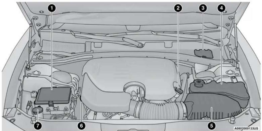
text_image
Technical diagram of a car engine bay with numbered components for identification1 — Power Distribution Center (Fuses) 5 — Engine Air Cleaner Filter
2 – Engine Oil Fill 6 – Engine Oil Dipstick
3 — Brake Fluid Reservoir Access Cover 7 — Washer Fluid Reservoir Cap
4 — Engine Coolant Pressure Reservoir
5.7L ENGINE
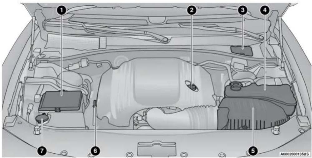
text_image
Diagram of a car engine bay with numbered components for identification1 — Power Distribution Center (Fuses) 5 — Engine Air Cleaner Filter
2 – Engine Oil Fill 6 – Engine Oil Dipstick
3 — Brake Fluid Reservoir Access Cover 7 — Washer Fluid Reservoir Cap
4 – Engine Coolant Pressure Reservoir
CHECKING OIL LEVEL
To ensure proper engine lubrication, the engine oil must be maintained at the correct level. Check the oil level at regular intervals, such as every month. The best time to check the engine oil level is about five minutes after a fully warmed up engine is shut off.
Checking the oil while the vehicle is on level ground will improve the accuracy of the oil level readings.
There are four possible dipstick types:
- Crosshatched zone.
• Crosshatched zone marked SAFE. - Crosshatched zone marked with MIN at the low end of the range and MAX at the high end of the range.
- Crosshatched zone marked with dimples at the MIN and the MAX ends of the range.
NOTE:
Always maintain the oil level within the cross-hatch markings on the dipstick.
Adding 1 quart (1.0 liters) of oil when the reading is at the low end of the dipstick range will raise the oil level to the high end of the range marking.
CAUTION!
Overfilling or underfilling the crankcase will cause aeration or loss of oil pressure. This could damage your engine.
ADDING WASHER FLUID
The windshield washer fluid reservoir is located in the front of the engine compartment. Be sure to check the fluid level at regular intervals. Fill the reservoir with windshield washer solvent (not radiator antifreeze) and operate the system for a few seconds to flush out the residual water.
When refilling the washer fluid reservoir, apply some washer fluid to a cloth or towel and wipe the wiper blades clean. This will help blade performance.
To prevent freeze-up of your windshield washer system in cold weather, select a solution or mixture that meets or exceeds the temperature range of your climate. This rating information can be found on most washer fluid containers.
The fluid reservoir will hold nearly 1 gallon (4 liters) of washer fluid when the message "Low Washer Fluid" appears in the instrument cluster.
WARNING!
Commercially available windshield washer solvents are flammable. They could ignite and burn you. Care must be exercised when filling or working around the washer solution.
MAINTENANCE-FREE BATTERY
Your vehicle is equipped with a maintenance-free battery. You will never have to add water, nor is periodic maintenance required.
NOTE:
The battery is stored under an access cover in the trunk. Remote battery terminals are located in the engine compartment for jump starting page 218.
WARNING!
- Battery fluid is a corrosive acid solution and can burn or even blind you. Do not allow battery fluid to contact your eyes, skin, or clothing. Do not lean over a battery when attaching clamps. If acid splashes in eyes or on skin, flush the area immediately with large amounts of water ➕ page 218.
- Battery gas is flammable and explosive. Keep flame or sparks away from the battery. Do not use a booster battery or any other booster source with an output greater than 12 Volts. Do not allow cable clamps to touch each other.
- Battery posts, terminals, and related accessories contain lead and lead compounds. Wash hands after handling.
- The battery in this vehicle has a vent hose that should not be disconnected and should only be replaced with a battery of the same type (vented).
CAUTION!
- It is essential when replacing the cables on the battery that the positive cable is attached to the positive post and the negative cable is attached to the negative post. Battery posts are marked positive (+) and negative (-) and are identified on the battery case. Cable clamps should be tight on the terminal posts and free of corrosion.
- If a “fast charger” is used while the battery is in the vehicle, disconnect both vehicle battery cables before connecting the charger to the battery. Do not use a “fast charger” to provide starting voltage.
PRESSURE WASHING
Cleaning the engine compartment with a high pressure washer is not recommended.
CAUTION!
Precautions have been taken to safeguard all parts and connections however, the pressures generated by these machines is such that complete protection against water ingress cannot be guaranteed.
VEHICLE MAINTENANCE
An authorized dealer has the qualified service personnel, special tools, and equipment to perform all service operations in an expert manner. Service Manuals are available which include detailed service information for your vehicle. Refer to these Service Manuals before attempting any procedure yourself.
NOTE:
Intentional tampering with emissions control systems may void your warranty and could result in civil penalties being assessed against you.
WARNING!
You can be badly injured working on or around a motor vehicle. Only do service work for which you have the knowledge and the proper equipment. If you have any doubt about your ability to perform a service job, take your vehicle to a competent mechanic.
ENGINE OIL
Engine Oil Selection — 3.6L And 5.7L Engine
For best performance and maximum protection under all types of operating conditions, the manufacturer only recommends engine oils that are API Certified and meet the requirements of FCA Material Standard MS-6395.
NOTE:
Hemi engines at times can tick right after startup and then quiet down after approximately 30 seconds. This is normal and will not harm the engine. This characteristic can be caused by short drive cycles. For example, if the vehicle is started then shut off after driving a short distance. Upon restarting, you may experience a ticking sound. Other causes could be if the vehicle is unused for an extended period of time, incorrect oil, extended oil changes or extended idling. If the engine continues to tick or if the Malfunction Indicator Light (MIL) comes on, see the nearest authorized dealer.
American Petroleum Institute (API) Engine Oil Identification Symbol

This symbol means that the oil has been certified by the American Petroleum Institute (API). The manufacturer only recommends API
Certified engine oils.
This symbol certifies 0W-20, 5W-20, 0W-30, 5W-30 and 10W-30 engine oils.
CAUTION!
Do not use chemical flushes in your engine oil as the chemicals can damage your engine. Such damage is not covered by the New Vehicle Limited Warranty.
Synthetic Engine Oils
You may use synthetic engine oils provided the recommended oil quality requirements are met, and the recommended maintenance intervals for oil and filter changes are followed.
Synthetic engine oils which do not have both the engine oil certification mark and the correct SAE viscosity grade number should not be used.
Materials Added To Engine Oil
The manufacturer strongly recommends against the addition of any additives (other than leak detection dyes) to the engine oil. Engine oil is an engineered product and its performance may be impaired by supplemental additives.
Disposing Of Used Engine Oil And Oil Filters
Care should be taken in disposing of used engine oil and oil filters from your vehicle. Used oil and oil filters, indiscriminately discarded, can present a problem to the environment. Contact an authorized dealer, service station or governmental agency for advice on how and where used oil and oil filters can be safely discarded in your area.
ENGINE OIL FILTER
The engine oil filter should be replaced with a new filter at every engine oil change.
Engine Oil Filter Selection
This manufacturer's engines have a full-flow type disposable oil filter. Use a filter of this type for replacement. The quality of replacement filters varies considerably. Only high quality filters should be used to ensure most efficient service. Mopar engine oil filters are high quality oil filters and are recommended.
ENGINE AIR CLEANER FILTER
For the proper maintenance intervals page 228.
WARNING!
The air induction system (air cleaner, hoses, etc.) can provide a measure of protection in the case of engine backfire. Do not remove the air induction system (air cleaner, hoses, etc.) unless such removal is necessary for repair or maintenance. Make sure that no one is near the engine compartment before starting the vehicle with the air induction system (air cleaner, hoses, etc.) removed. Failure to do so can result in serious personal injury.
Engine Air Cleaner Filter Selection
The quality of replacement engine air cleaner filters varies considerably. Only high quality filters should be used to ensure most efficient service. Mopar engine air cleaner filters are a high quality filter and are recommended.
AIR CONDITIONER MAINTENANCE
For best possible performance, your air conditioner should be checked and serviced by an authorized dealer at the start of each warm season. This service should include cleaning of the condenser fins and a performance test. Drive belt tension should also be checked at this time.
WARNING!
- Use only refrigerants and compressor lubricants approved by the manufacturer for your air conditioning system. Some unapproved refrigerants are flammable and can explode, injuring you. Other unapproved refrigerants or lubricants can cause the system to fail, requiring costly repairs. Refer to Warranty Information Book, for further warranty information.
(Continued)
WARNING! (Continued)
- The air conditioning system contains refrigerant under high pressure. To avoid risk of personal injury or damage to the system, adding refrigerant or any repair requiring lines to be disconnected should be done by an experienced technician.
CAUTION!
Do not use chemical flushes in your air conditioning system as the chemicals can damage your air conditioning components. Such damage is not covered by the New Vehicle Limited Warranty.
Refrigerant Recovery And Recycling R-134a — If Equipped
R-134a Air Conditioning Refrigerant is a hydrofluorocarbon (HFC) that is an ozone-friendly substance. The manufacturer recommends that air conditioning service be performed by an authorized dealer or other service facilities using recovery and recycling equipment.
238 SERVICING AND MAINTENANCE
NOTE:
Use only manufacturer approved A/C system PAG compressor oil and refrigerants.
Refrigerant Recovery And Recycling R-1234yf — If Equipped
R-1234yf Air Conditioning Refrigerant is a hydrofluorolefin (HFO) that is endorsed by the Environmental Protection Agency and is an ozone-friendly substance with a low global-warming potential. The manufacturer recommends that air conditioning service be performed by an authorized dealer using recovery and recycling equipment.
NOTE:
Use only manufacturer approved A/C system PAG compressor oil, and refrigerants.
Cabin Air Filter
The cabin air filter is located in the fresh air inlet under the hood, behind a removable panel in the cowl on the passenger side of the vehicle, next to the windshield wipers. When installing a new cabin air filter, ensure its proper orientation.
- Remove the access door in the cowl screen by pressing the retaining clips.
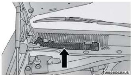
natural_image
Mechanical assembly diagram showing a spring-loaded component with a black arrow pointing to it, no visible text or symbols.Access Door
- Unsnap both ends and lift the cabin air filter access cover.

natural_image
Technical diagram showing a mechanical component with an upward arrow, no readable text or symbols present.Filter Access Cover
- Remove the used cabin air filter.
- Install the new cabin air filter with arrows pointing in the direction of airflow, which is toward the rear of the vehicle (text and arrows on the cabin air filter will indicate this).
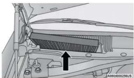
natural_image
Mechanical assembly diagram showing a heat sink component with mounting bracket and housing (no text or symbols)Cabin Air Filter
- Close the cabin air filter access cover.
For the proper maintenance intervals page 228.
ACCESSORY DRIVE BELT INSPECTION
WARNING!
- Do not attempt to inspect an accessory drive belt with vehicle running.
- When working near the radiator cooling fan, disconnect the fan motor lead. The fan is temperature controlled and can start at any time regardless of ignition mode. You could be injured by the moving fan blades.
- You can be badly injured working on or around a motor vehicle. Only do service work for which you have the knowledge and the proper equipment. If you have any doubt about your ability to perform a service job, take your vehicle to a competent mechanic.
When inspecting accessory drive belts, small cracks that run across ribbed surface of belt from rib to rib, are considered normal. These are not a reason to replace belt. However, cracks running along a rib (not across) are not normal. Any belt with cracks running along a rib must be replaced. Also have the belt replaced if it has excessive wear, frayed cords or severe glazing.
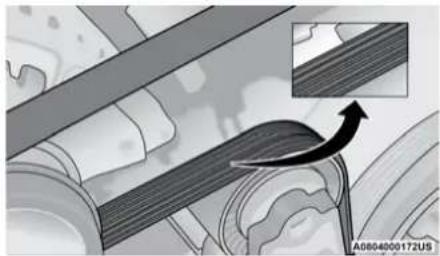
natural_image
Mechanical assembly diagram showing a rotating component with an inset view of a curved arrow (no text or symbols)Accessory Belt (Serpentine Belt)
Conditions that would require replacement:
- Rib chunking (one or more ribs has separated from belt body)
- Rib or belt wear
- Longitudinal belt cracking (cracks between two ribs)
- Belt slips
- "Groove jumping" (belt does not maintain correct position on pulley)
- Belt broken (note: identify and correct problem before new belt is installed)
- Noise (objectionable squeal, squeak, or rumble is heard or felt while drive belt is in operation)
Some conditions can be caused by a faulty component such as a belt pulley. Belt pulleys should be carefully inspected for damage and proper alignment.
Belt replacement on some models requires the use of special tools, we recommend having your vehicle serviced at an authorized dealer.
BODY LUBRICATION
Locks and all body pivot points, including such items as seat tracks, door hinge pivot points and rollers, liftgate, tailgate, decklid, sliding doors and hood hinges, should be lubricated periodically with a lithium-based grease, such as Mopar Spray White Lube to ensure quiet, easy operation and to protect against rust and wear. Prior to the application of any lubricant, the parts concerned should be wiped clean to remove dust and grit; after lubricating, excess oil and grease should be removed. Particular attention should also be given to hood latching components to ensure proper function. When performing other underhood services, the hood latch, release mechanism and safety catch should be cleaned and lubricated.
The external lock cylinders should be lubricated twice a year, preferably in the Autumn and Spring. Apply a small amount of a high quality lubricant, such as Mopar Lock Cylinder Lubricant directly into the lock cylinder.
WINDSHIELD WIPER BLADES
Clean the rubber edges of the wiper blades and the windshield periodically with a sponge or soft cloth and a mild nonabrasive cleaner. This will remove accumulations of salt or road film.
Operation of the wipers on dry glass for long periods may cause deterioration of the wiper blades. Always use washer fluid when using the wipers to remove salt or dirt from a dry windshield.
Avoid using the wiper blades to remove frost or ice from the windshield. Keep the blade rubber out of contact with petroleum products such as engine oil, gasoline, etc.
NOTE:
Life expectancy of wiper blades varies depending on geographical area and frequency of use. Poor performance of blades may be present with chattering, marks, water lines or wet spots. If any of these conditions are present, clean the wiper blades or replace as necessary.
Wiper Blade Removal/Installation
CAUTION!
Do not allow the wiper arm to spring back against the glass without the wiper blade in place or the glass may be damaged.
- Lift the wiper arm to raise the wiper blade off of the glass, until the wiper arm is in the full up position.
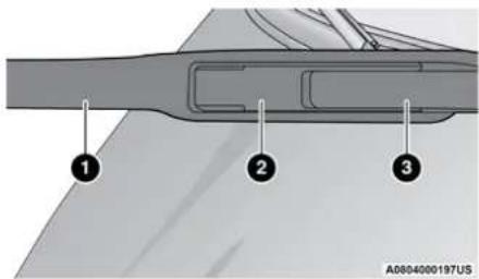
text_image
1 2 3 A0804000197USWindshield Wiper Arm
1-Wiper
2 - Locking Tab
3-Wiper Arm
- To disengage the wiper blade from the wiper arm, flip up the locking tab.
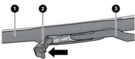
text_image
Diagram of a mechanical assembly with numbered components and directional arrow indicating motion or forceA0804000198US
Wiper Locking Assembly
1-Wiper
2 - Locking Tab
3-Wiper Arm
-
Slide the wiper blade down towards the base of the wiper arm.
-
With the wiper blade disengaged, remove the wiper blade from the wiper arm by holding the wiper arm with one hand and separating the wiper blade from the wiper arm with the other hand (move the wiper blade down toward the base of the wiper arm and away from the J hook in the end of the wiper arm).
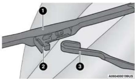
text_image
Technical diagram showing three labeled mechanical components with numbered annotationsRemoving Wiper From Wiper Arm
1-Wiper
2 - Locking Tab
3 — Wiper Arm J Hook
- Gently lower the wiper arm onto the glass.
Installing The Front Wipers
- Lift the wiper arm off of the glass, until the wiper arm is in the full up position.
- Position the wiper blade under the hook on the tip of the wiper arm with the wiper locking tab open.
- Insert the receiver bracket on the wiper assembly into the hook on the tip of the arm through the opening in the wiper blade under the locking tab.
- Slide the wiper blade onto the arm until motion stops, then fold down the locking tab to secure.
NOTE:
The locking tab will not snap into place until the blade is properly positioned on the wiper arm hook.
5. Gently lower the wiper blade onto the glass.
EXHAUST SYSTEM
The best protection against carbon monoxide entry into the vehicle body is a properly maintained engine exhaust system.
If you notice a change in the sound of the exhaust system; or if the exhaust fumes can be detected inside the vehicle; or when the underside or rear of the vehicle is damaged; have an authorized technician inspect the complete exhaust system and adjacent body areas for broken, damaged, deteriorated, or mispositioned parts. Open seams or loose connections could permit exhaust fumes to seep into the passenger compartment. In addition, have the exhaust system inspected each time the vehicle is raised for lubrication or oil change. Replace as required.
WARNING!
- Exhaust gases can injure or kill. They contain carbon monoxide (CO), which is colorless and odorless. Breathing it can make you unconscious and can eventually poison you. To avoid breathing CO page 209.
- A hot exhaust system can start a fire if you park over materials that can burn. Such materials might be grass or leaves coming into contact with your exhaust system. Do not park or operate your vehicle in areas where your exhaust system can contact anything that can burn.
CAUTION!
- The catalytic converter requires the use of unleaded fuel only. Leaded gasoline will destroy the effectiveness of the catalyst as an emissions control device and may seriously reduce engine performance and cause serious damage to the engine.
(Continued)
CAUTION! (Continued)
- Damage to the catalytic converter can result if your vehicle is not kept in proper operating condition. In the event of engine malfunction, particularly involving engine misfire or other apparent loss of performance, have your vehicle serviced promptly. Continued operation of your vehicle with a severe malfunction could cause the converter to overheat, resulting in possible damage to the converter and vehicle.
Under normal operating conditions, the catalytic converter will not require maintenance. However, it is important to keep the engine properly tuned to ensure proper catalyst operation and prevent possible catalyst damage.
NOTE:
Intentional tampering with emissions control systems can result in civil penalties being assessed against you.
In unusual situations involving grossly malfunctioning engine operation, a scorching odor may suggest severe and abnormal catalyst overheating. If this occurs, stop the vehicle, turn off the engine and allow it to cool. Service, including a tune-up to manufacturer's specifications, should be obtained immediately.
To minimize the possibility of catalytic converter damage:
- Do not shut off the engine or interrupt the ignition when the transmission is in gear and the vehicle is in motion.
- Do not try to start the engine by pushing or towing the vehicle.
- Do not idle the engine with any spark plug wires disconnected or removed, such as when diagnostic testing, or for prolonged periods during very rough idle or malfunctioning operating conditions.
NOTE:
Your vehicle's exhaust system may be equipped with an Electronic Exhaust Valve (EEV) system, if the exhaust system is replaced with after-market products a Malfunction Indicator Lamp (MIL) will illuminate.
COOLING SYSTEM
WARNING!
- You or others can be badly burned by hot engine coolant (antifreeze) or steam from your radiator. If you see or hear steam coming from under the hood, do not open the hood until the radiator has had time to cool. Never open a cooling system pressure cap when the radiator or coolant bottle is hot.
- Keep hands, tools, clothing, and jewelry away from the radiator cooling fan when the hood is raised. The fan starts automatically and may start at any time, whether the engine is running or not.
- When working near the radiator cooling fan disconnect the fan motor lead or turn the ignition to the OFF mode. The fan is temperature controlled and can start at any time the ignition is in the ON mode.
Coolant Checks
Check engine coolant (antifreeze) protection every 12 months (before the onset of freezing weather, where applicable). If the engine coolant is dirty, the system should be drained,
flushed, and refilled with fresh Organic Additive Technology (OAT) coolant (conforming to MS.90032) by an authorized dealer. Check the front of the radiator for any accumulation of bugs, leaves, etc. If dirty, clean by gently spraying water from a garden hose vertically down the face of the condenser.
Check the coolant recovery bottle tubing for brittle rubber, cracking, tears, cuts, and tightness of the connection at the bottle and radiator. Inspect the entire system for leaks. DO NOT REMOVE THE COOLANT PRESSURE CAP WHEN THE COOLING SYSTEM IS HOT.
Cooling System — Drain, Flush And Refill
NOTE:
Some vehicles require special tools to add coolant properly. Failure to fill these systems properly could lead to severe internal engine damage. If any coolant is needed to be added to the system please contact an authorized dealer.
If the engine coolant (antifreeze) is dirty or contains visible sediment, have an authorized dealer clean and flush with Organic Additive Technology (OAT) coolant (conforming to MS.90032).
For the proper maintenance intervals ➤ page 228.
Selection Of Coolant
For further information → page 291.
NOTE:
- Mixing of engine coolant (antifreeze) other than specified Organic Additive Technology (OAT) engine coolant, may result in engine damage and may decrease corrosion protection. OAT engine coolant is different and should not be mixed with Hybrid Organic Additive Technology (HOAT) engine coolant or any “globally compatible” coolant. If a non-OAT engine coolant is introduced into the cooling system in an emergency, the cooling system will need to be drained, flushed, and refilled with fresh OAT coolant (conforming to MS.90032), by an authorized dealer as soon as possible.
- Do not use water alone or alcohol-based engine coolant products. Do not use additional rust inhibitors or anti-rust products, as they may not be compatible with the radiator engine coolant and may plug the radiator.
244 SERVICING AND MAINTENANCE
- This vehicle has not been designed for use with propylene glycol-based engine coolant. Use of propylene glycol-based engine coolant is not recommended.
- Some vehicles require special tools to add coolant properly. Failure to fill these systems properly could lead to severe internal engine damage. If any coolant is needed to be added to the system please contact an authorized dealer.
Adding Coolant
Your vehicle has been built with an improved engine coolant (OAT coolant conforming to MS.90032) that allows extended maintenance intervals. This engine coolant (antifreeze) can be used up to 10 years or 150,000 miles (240,000 km) before replacement. To prevent reducing this extended maintenance period, it is important that you use the same engine coolant (OAT coolant conforming to MS.90032) throughout the life of your vehicle.
Please review these recommendations for using Organic Additive Technology (OAT) engine coolant that meets the requirements of FCA Material Standard MS.90032. When adding engine coolant:
- We recommend using Mopar Antifreeze/ Coolant 10 Year/150,000 Mile (240,000 km) Formula OAT that meets the requirements of FCA Material Standard MS.90032.
- Mix a minimum solution of 50% OAT engine coolant that meets the requirements of FCA Material Standard MS.90032 and distilled water. Use higher concentrations (not to exceed 70%) if temperatures below -34^ F ( -37^ C) are anticipated. Please contact an authorized dealer for assistance.
- Use only high purity water such as distilled or deionized water when mixing the water/ engine coolant solution. The use of lower quality water will reduce the amount of corrosion protection in the engine cooling system.
NOTE:
- It is the owner's responsibility to maintain the proper level of protection against freezing according to the temperatures occurring in the area where the vehicle is operated.
- Some vehicles require special tools to add coolant properly. Failure to fill these systems properly could lead to severe internal engine
damage. If any coolant is needed to be added to the system, please contact a local authorized dealer.
- Mixing engine coolant types is not recommended and can result in cooling system damage. If HOAT and OAT coolant are mixed in an emergency, have a authorized dealer drain, flush, and refill with OAT coolant (conforming to MS.90032) as soon as possible.
Cooling System Pressure Cap
The cap must be fully tightened to prevent loss of engine coolant (antifreeze), and to ensure that engine coolant will return to the radiator from the coolant expansion bottle/recovery tank if equipped.
The cap should be inspected and cleaned if there is any accumulation of foreign material on the sealing surfaces.
WARNING!
- Do not open hot engine cooling system. Never add engine coolant (antifreeze) when the engine is overheated. Do not loosen or remove the cap to cool an overheated engine. Heat causes pressure to build up in the cooling system. To prevent scalding or injury, do not remove the pressure cap while the system is hot or under pressure.
- Do not use a pressure cap other than the one specified for your vehicle. Personal injury or engine damage may result.
Disposal Of Used Coolant
Used ethylene glycol-based coolant (antifreeze) is a regulated substance requiring proper disposal. Check with your local authorities to determine the disposal rules for your community. To prevent ingestion by animals or children, do not store ethylene glycol-based coolant in open containers or allow it to remain in puddles on the ground, clean up any ground spills immediately. If ingested by a child or pet, seek emergency assistance immediately.
Coolant Level
The coolant bottle provides a quick visual method for determining that the coolant level is adequate. With the engine off and cold, the level of the engine coolant (antifreeze) in the bottle should be between the ranges indicated on the bottle.
The radiator normally remains completely full, so there is no need to remove the radiator/coolant pressure cap unless checking for engine coolant freeze point or replacing coolant. Advise your service attendant of this. As long as the engine operating temperature is satisfactory, the coolant bottle need only be checked once a month.
When additional engine coolant is needed to maintain the proper level, only OAT coolant that meets the requirements of FCA Material Standard MS.90032 should be added to the coolant bottle. Do not overfill.
Cooling System Notes
NOTE:
When the vehicle is stopped after a few miles/kilometers of operation, you may observe vapor coming from the front of the engine compartment. This is normally a result of moisture from rain, snow, or high humidity accumulating on the radiator and being vaporized when the thermostat opens, allowing hot engine coolant (anti-freeze) to enter the radiator.
If an examination of your engine compartment shows no evidence of radiator or hose leaks, the vehicle may be safely driven. The vapor will soon dissipate.
- Do not overfill the coolant expansion bottle.
- Check the coolant freeze point in the radiator and in the coolant expansion bottle. If engine coolant needs to be added, the contents of the coolant expansion bottle must also be protected against freezing.
- If frequent engine coolant additions are required, the cooling system should be pressure tested for leaks.
- Maintain engine coolant concentration at a minimum of 50% OAT coolant (conforming to MS.90032) and distilled water for proper corrosion protection of your engine which contains aluminum components.
-
Make sure that the coolant expansion bottle overflow hoses are not kinked or obstructed.
-
Keep the front of the radiator clean. If your vehicle is equipped with air conditioning, keep the front of the condenser clean.
- Do not change the thermostat for Summer or Winter operation. If replacement is ever necessary, install ONLY the correct type thermostat. Other designs may result in unsatisfactory engine cooling performance, poor gas mileage, and increased emissions.
BRAKE SYSTEM
In order to ensure brake system performance, all brake system components should be inspected periodically ↩ page 228.
WARNING!
Riding the brakes can lead to brake failure and possibly a collision. Driving with your foot resting or riding on the brake pedal can result in abnormally high brake temperatures, excessive lining wear, and possible brake damage. You would not have your full braking capacity in an emergency.
Fluid Level Check — Brake Master Cylinder
Check the fluid level in the master cylinder immediately if the brake system warning light indicates system failure.
Check the fluid level in the master cylinder when performing underhood services.
Clean the top of the master cylinder area before removing the cap. Add fluid to bring the level up to the top of the "FULL" mark on the side of the master cylinder reservoir.
Overfilling of fluid is not recommended because it may cause leaking in the system.
Add enough fluid to bring the level up to the requirements described on the brake fluid reservoir. With disc brakes, fluid level can be expected to fall as the brake pads wear. However, low fluid level may be caused by a leak and a checkup may be needed.
Use only brake fluid that has been recommended by the manufacturer, and has been kept in a tightly closed container to avoid contamination from foreign matter or moisture page 293.
WARNING!
- Use only manufacturer's recommended brake fluid ➕ page 293. Using the wrong type of brake fluid can severely damage your brake system and/or impair its performance. The proper type of brake fluid for your vehicle is also identified on the original factory installed hydraulic master cylinder reservoir.
- To avoid contamination from foreign matter or moisture, use only new brake fluid or fluid that has been in a tightly closed container. Keep the master cylinder reservoir cap secured at all times. Brake fluid in a open container absorbs moisture from the air resulting in a lower boiling point. This may cause it to boil unexpectedly during hard or prolonged braking, resulting in sudden brake failure. This could result in a collision.
- Overfilling the brake fluid reservoir can result in spilling brake fluid on hot engine parts, causing the brake fluid to catch fire. Brake fluid can also damage painted and vinyl surfaces, care should be taken to avoid its contact with these surfaces.
(Continued)
WARNING! (Continued)
- Do not allow petroleum based fluid to contaminate the brake fluid. Brake seal components could be damaged, causing partial or complete brake failure. This could result in a collision.
AUTOMATIC TRANSMISSION
Special Additives
The manufacturer strongly recommends against using any special additives in the transmission. Automatic Transmission Fluid (ATF) is an engineered product and its performance may be impaired by supplemental additives. Therefore, do not add any fluid additives to the transmission. Avoid using transmission sealers as they may adversely affect seals.
CAUTION!
Do not use chemical flushes in your transmission as the chemicals can damage your transmission components. Such damage is not covered by the New Vehicle Limited Warranty.
Fluid Level Check
The fluid level is preset at the factory and does not require adjustment under normal operating conditions. Routine fluid level checks are not required; therefore the transmission has no dipstick. An authorized dealer can check your transmission fluid level using special service tools. If you notice fluid leakage or transmission malfunction, visit an authorized dealer immediately to have the transmission fluid level checked. Operating the vehicle with an improper fluid level can cause severe transmission damage.
CAUTION!
If a transmission fluid leak occurs, visit an authorized dealer immediately. Severe transmission damage may occur. An authorized dealer has the proper tools to adjust the fluid level accurately.
Fluid And Filter Changes
Under normal operating conditions, the fluid installed at the factory will provide satisfactory lubrication for the life of the vehicle.
SERVICING AND MAINTENANCE 247
Routine fluid and filter changes are not required. However, change the fluid and filter if the fluid becomes contaminated (with water, etc.), or if the transmission is disassembled for any reason.
Selection Of Lubricant
It is important to use the proper transmission fluid to ensure optimum transmission performance and life. Use only the manufacturer's specified transmission fluid ➤ page 293. It is important to maintain the transmission fluid at the correct level using the recommended fluid.
NOTE:
No chemical flushes should be used in any transmission; only the approved lubricant should be used.
CAUTION!
Using a transmission fluid other than the manufacturer's recommended fluid may cause deterioration in transmission shift quality and/or torque converter shudder page 293.
ALL WHEEL DRIVE (AWD) — IF EQUIPPED
The All Wheel Drive system consists of a transfer case and front differential. The exterior surface of these components should be inspected for evidence of fluid leaks. Confirmed leaks should be repaired as soon as possible.
The transfer case fluid fill/inspection plug is located in the middle of the rear housing. To inspect the transfer case fluid level, remove the fill/inspection plug. The fluid level should be even with the bottom of the hole. Use this plug to add fluid as required.
The front differential fill plug is located on the outer cover near the half shaft attachment. To inspect the differential fluid level, remove the fill plug. The fluid level should be even with or slightly below the bottom of the hole.
Fluid Changes
For the proper maintenance intervals → page 228.
REAR AXLE
For normal service, periodic fluid level checks are not required. When the vehicle is serviced for other reasons the exterior surfaces of the axle assembly should be inspected. If gear oil leakage is suspected inspect the fluid level page 293.
FUSES
WARNING!
- When replacing a blown fuse, always use an appropriate replacement fuse with the same amp rating as the original fuse. Never replace a fuse with another fuse of higher amp rating. Never replace a blown fuse with metal wires or any other material. Do not place a fuse inside a circuit breaker cavity or vice versa. Failure to use proper fuses may result in serious personal injury, fire and/or property damage.
- Before replacing a fuse, make sure that the ignition is off and that all the other services are switched off and/or disengaged.
(Continued)
WARNING! (Continued)
- If the replaced fuse blows again, contact an authorized dealer.
- If a general protection fuse for safety systems (air bag system, braking system), power unit systems (engine system, transmission system) or steering system blows, contact an authorized dealer.
General Information
WARNING!
- When replacing a blown fuse, always use an appropriate replacement fuse with the same amp rating as the original fuse. Never replace a fuse with another fuse of higher amp rating. Never replace a blown fuse with metal wires or any other material. Do not place a fuse inside a circuit breaker cavity or vice versa. Failure to use proper fuses may result in serious personal injury, fire and/or property damage.
(Continued)
WARNING! (Continued)
- Before replacing a fuse, make sure that the ignition is off and that all the other services are switched off and/or disengaged.
- If the replaced fuse blows again, contact an authorized dealer.
- If a general protection fuse for safety systems (air bag system, braking system), power unit systems (engine system, transmission system) or steering system blows, contact an authorized dealer.
The fuses protect electrical systems against excessive current.
When a device does not work, you must check the fuse element inside the blade fuse for a break/melt.
Also, please be aware that when using power outlets for extended periods of time with the engine off may result in vehicle battery discharge.
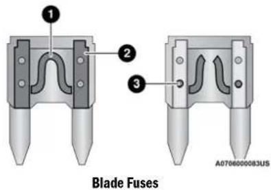
text_image
Blade Fuses A0706000083US1-Fuse Element
2 - Blade Fuse with a good/ functional fuse element.
3 - Blade fuse with a bad/ not functional fuse element (blown fuse).
Underhood Fuses
The Front Power Distribution Center is located in the engine compartment. This module contains fuses and relays. Fuse cavity location and descriptions are printed on the inside of the power distribution center cover.
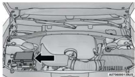
natural_image
Interior view of a car showing engine compartment with a black arrow pointing to a component (no text or symbols visible)Front Power Distribution Center
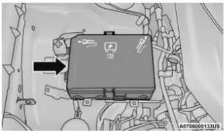
natural_image
Interior view of a vehicle engine bay with a black component and directional arrow (no visible text or symbols)Front Power Distribution Center
CAUTION!
- When installing the power distribution center cover, it is important to ensure the cover is properly positioned and fully latched. Failure to do so may allow water to get into the power distribution center and possibly result in an electrical system failure.
(Continued)
CAUTION! (Continued)
- When replacing a blown fuse, it is important to use only a fuse having the correct amperage rating. The use of a fuse with a rating other than indicated may result in a dangerous electrical system overload. If a properly rated fuse continues to blow, it indicates a problem in the circuit that must be corrected.
| Cavity Cartridge Fuse Mini-Fuse Description | |||
| 1 - - Fuse - Spare | |||
| 2 40 Amp Green - Radiator Fan #1 - (Non 6.2L Supercharged) | |||
| 3 50 Amp Red - Electric Power Steering #1 - If Equipped | |||
| 4 30 Amp Pink - Starter | |||
| 5 40 Amp Green - Anti Lock Brake | |||
| 6 30 Amp Pink - Anti Lock Brake | |||
| 7 20 Amp Blue - Police Ignition Run / ACC #1 | |||
| 9 - | 20 Amp Yellow All-Wheel Drive Module - If Equipped | ||
| 10 | - 10 Amp Red | Intrusion MOD (300) - If Equipped / Under Hood Lamp - Police | |
| 11 | - | 20 Amp Yellow | Horns |
| 12 | - 10 Amp Red | Air Conditioning Clutch | |
| 13 | - - Fuse - Spare | ||
| 14 | - - Fuse - Spare | ||
| 15 | - | 20 Amp Yellow | Left HID Headlamp - If Equipped |
| 16 | - | 20 Amp Yellow | Right HID Headlamp - If Equipped |
252 SERVICING AND MAINTENANCE
| Cavity Cartridge Fuse | Mini-Fuse | Description | |
| 18 50 Amp Red - Radiator Fan - (Non 6.2L Supercharged) | |||
| 19 50 Amp Red - Electric Power Steering #2 - If Equipped | |||
| 20 30 Amp Pink - Wiper Motor | |||
| 21 | 30 Amp Pink20 Amp Blue - Police | - | Headlamp Washers - If EquippedPolice Bat Feed #2 |
| 23 20 Amp Blue - Police Bat Feed # 1 | |||
| 28 -- Fuse - Spare | |||
| 29 - 15 Amp Blue | Transmission Control Module (Challenger / Charger Police) | ||
| 30 -- Fuse - Spare | |||
| 31 - 25 Amp Clear Engine Module | |||
| 32 -- Fuse - Spare | |||
| 33 -- Fuse - Spare | |||
| 34 - 25 Amp Clear ASD Feed #1 | |||
| 35 - 20 Amp Yellow ASD Feed #2 | |||
| 36 - 10 Amp Red | Anti-Lock Brake Module / Steering Column Lock Module (300 if equipped) | ||
| Cavity Cartridge Fuse Mini-Fuse Description | ||
| 37 – 10 Amp Red Engine Controller | ||
| 38 – 10 Amp Red Airbag Module | ||
| 39 – 10 Amp Red | A/C Clutch / EPS – If Equipped / Vacuum Pump – If Equipped | |
| 48 – 10 Amp Red AWD Module / Front Axle Disconnect – If Equipped | ||
| 49 – – Fuse – Spare | ||
| 50 – – Fuse – Spare | ||
| 51 – 20 Amp Yellow Vacuum Pump – If Equipped | ||
| 52 – 5 Amp Tan Adaptive Cruise – If Equipped | ||
| 53 – – Fuse – Spare |
Rear Interior Fuses
There is also a power distribution center located in the trunk under the spare tire access panel. This center contains fuses and relays. Fuse cavity location and descriptions are printed on the inside of the power distribution center cover.
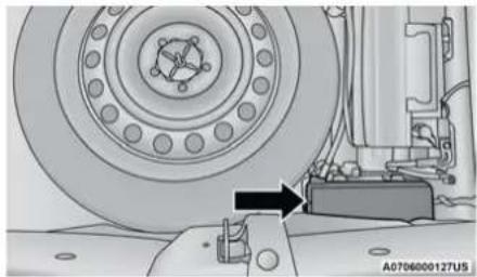
natural_image
Mechanical assembly diagram showing a wheel and brake component with an arrow indicating motion (no text or symbols present)Rear Power Distribution Center
CAUTION!
- When installing the power distribution center cover, it is important to ensure the cover is properly positioned and fully latched. Failure to do so may allow water to get into the power distribution center and possibly result in an electrical system failure.
- When replacing a blown fuse, it is important to use only a fuse having the correct amperage rating. The use of a fuse with a rating other than indicated may result in a dangerous electrical system overload. If a properly rated fuse continues to blow, it indicates a problem in the circuit that must be corrected.
| Cavity Cartridge Fuse Mini-Fuse Description | |||
| 2 60 Amp Yellow - Front PDC Feed #1 | |||
| 3 - - Fuse - Spare | |||
| 4 60 Amp Yellow - Front PDC Feed #2 | |||
| 5 | 30 Amp Pink20 Amp Blue - Police | - Sunroof/Dome Lamp - Police | |
| 6 40 Amp Green - Exterior Lighting #1 | |||
| Cavity Cartridge Fuse | Mini-Fuse | Description | |
| 7 40 Amp Green - Exterior Lighting #2 | |||
| 8 30 Amp Pink - Interior Lighting | |||
| 9 40 Amp Green - Power Locks | |||
| 10 30 Amp Pink - Driver Door Control Module | |||
| 11 30 Amp Pink - Passenger Door Control Module | |||
| 12 - 20 Amp Yellow | Dual USB Center Console Rear/+12 Volt Power Outlet IP - IfEquipped / IP APO - If Equipped | ||
| 15 40 Amp Green - HVAC Blower | |||
| 16 20 Amp Blue - Left Spot Lamp - Police | |||
| 17 20 Amp Blue - Right Spot Lamp - Police | |||
| 18 30 Amp Pink - Mod Network Interface - Police | |||
| 19 - - Fuse - Spare | |||
| 20 - - Fuse - Spare | |||
| 21 30 Amp Pink - Fuel Pump (Non 6.2L SRT) | |||
| 22 - 5 Amp Tan Cyber Gateway Module | |||
| 23 - 10 Amp Red | Fuel Door - If Equipped/Diagnostic Port | ||
| 24 - 10 Amp Red Integrated Center Stack | |||
| 25 - 10 Amp Red Tire Pressure Monitor System | |||
256 SERVICING AND MAINTENANCE
| Cavity | Cartridge Fuse | Mini-Fuse | Description |
| 26 - 15 Amp Blue | Cygnus Transmission Module (Charger Non - Police/300) | ||
| 27 - 25 Amp Clear Amplifier - If Equipped | |||
| 31 - 25 Amp Breaker Power Seats - If Equipped | |||
| 32 - 15 Amp Blue HVAC Module/Cluster | |||
| 33 - 15 Amp Blue | Ignition Switch/RF Hub Module/ Steering Column Lock (300) - If Equipped / Remote Start - If Equipped | ||
| 34 - 10 Amp Red | Steering Column Module/Clock (300) | ||
| 35 - 5 Amp Tan Battery Sensor | |||
| 36 - 15 Amp Blue | Electronic Exhaust Valve - If Equipped | ||
| 37 - 20 Amp Yellow Radio | |||
| 38 - 20 Amp Yellow Media Hub / Console APO | |||
| 42 30 Amp Pink - Rear Defrost | |||
| 43 - 20 Amp Yellow | Rear Heated Seats - If Equipped / Heated Steering Wheel - If Equipped | ||
| 44 - 10 Amp Red | Park Assist / Blind Spot / Rear View Camera |
| Cavity Cartridge Fuse Mini-Fuse Description | ||
| 45 - 15 Amp Blue | Cluster / Rearview Mirror / Lane Departure | |
| 46 - - Fuse - Spare | ||
| 47 - 10 Amp Red | Adaptive Front Lighting / Day Time Running Lamps - If Equipped | |
| 49 - - Fuse - Spare | ||
| 50 - - Fuse - Spare | ||
| 51 - 20 Amp Yellow | Front Heated / Vented Seats - If Equipped | |
| 52 - 10 Amp Red | Heated/Cooled Cup Holders/Rear Heated Seat Switches - If Equipped | |
| 53 - 10 Amp Red | HVAC Module/In Vehicle Temperature Sensor | |
| 54 - - Fuse - Spare | ||
| 55 - - Fuse - Spare | ||
| 56 - - Fuse - Spare | ||
| 57 - - Fuse - Spare | ||
| 58 - 10 Amp Red Airbag Module | ||
| 59 - 20 Amp Yellow Adjustable Pedals - Police | ||
| 60 - - Fuse - Spare | ||
| 61 - - Fuse - Spare |
258 SERVICING AND MAINTENANCE
| Cavity Cartridge Fuse Mini-Fuse Description | ||
| 62 -- Fuse - Spare | ||
| 63 -- Fuse - Spare | ||
| 64 - 25 Amp Breaker Rear Windows (Charger/300) | ||
| 65 - 10 Amp Red Airbag Module | ||
| 66 -- Fuse - Spare | ||
| 67 - 10 Amp Red | Rain and Light Sensor / Sunroof / Inside RearView Mirror / Police Run Acc Relay | |
| 68 - 10 Amp Red | Rear USB Timer / Rear Sunshade - If Equipped | |
| 69 -- Fuse - Spare | ||
| 70 -- Fuse - Spare |
BULB REPLACEMENT
Replacement Bulbs
All of the interior bulbs are glass wedge base or glass cartridge types. Aluminum base bulbs are not approved and should not be used for replacement.
| Interior Bulbs | |
| Bulb Name Bulb Number | |
| Rear Courtesy/Reading Lamps W5W | |
| Rear Compartment (Trunk) Lamp 562 | |
| Overhead Console Reading Lamps 578 | |
| Visor Vanity Lamps A6220 | |
| Glove Compartment Lamp - If Equipped 194 | |
| Door Courtesy 562 | |
| Shift Indicator Lamp JKLE14140 | |
| Optional Door Map Pocket/Cupholder LED (Serviced at an authorized dealer) | |
| For lighted switches, see an authorized dealer for replacement instructions. | |
| Exterior Bulbs | |
| Bulb Name Bulb Number | |
| Low Beam/High Beam (Bi-Halogen Headlamp) 9005HL+ | |
| Low Beam/High Beam (Bi-Xenon Headlamp) D3S (Serviced at an authorized dealer) | |
| Front Turn Signal Lamp PSY24WSV | |
| Front Park Lamp LED (Serviced at an authorized dealer) | |
| Daytime Running Lamp LED (Serviced at an authorized dealer) | |
| Front Fog Lamp – If Equipped LED (Serviced at an authorized dealer) | |
| Front Side marker Lamp LED (Serviced at an authorized dealer) | |
| Rear Tail/Stop/Turn Lamp LED (Serviced at an authorized dealer) | |
| Rear Side marker Lamp LED (Serviced at an authorized dealer) | |
| Backup Lamp LED (Serviced at an authorized dealer) | |
| Center High Mounted Stop Lamp (CHMSL) LED (Serviced at an authorized dealer) | |
| License LED (Serviced at an authorized dealer) | |
Replacing Exterior Bulbs
High Intensity Discharge (HID) Headlamps — If Equipped
The headlamps are a type of high voltage discharge tube. High voltage can remain in the circuit even with the headlamp switch off and the ignition turned to the OFF position. Because of this, you should not attempt to service a headlamp bulb yourself. If a headlamp bulb fails, take your vehicle to an authorized dealer for service.
WARNING!
A transient high voltage occurs at the bulb sockets of HID headlamps when the headlamp switch is turned ON. It may cause serious electrical shock or electrocution if not serviced properly. See an authorized dealer for service.
NOTE:
On vehicles equipped with HID headlamps, when the headlamps are turned on, there is a blue hue to the lights. This diminishes and becomes more white after approximately 10 seconds, as the system charges.
Bi-Halogen Low Beam And High Beam Headlamp — If Equipped
See steps below to replace:
- Open the hood.
NOTE:
Removal of the air cleaner filter housing may be necessary prior to replacing bulbs in the head-lamp assembly on the driver side of the vehicle.
- Reach behind the headlamp housing to access the headlamp (outboard) bulb cap.
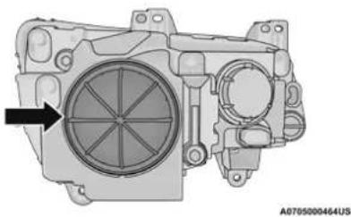
natural_image
Technical illustration of a mechanical component with a circular housing and mounting holes (no text or symbols)Headlamp Bulb Cap
-
Firmly grab the cap and rotate it counterclockwise to unlock it.
-
Twist the headlamp bulb assembly counterclockwise, and then pull it out of the headlamp assembly.
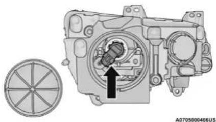
natural_image
Mechanical assembly diagram showing a motor or engine component with a highlighted valve and a circular base (no text or symbols)Headlamp Bulb Location
-
Disconnect the bulb from the wiring assembly and install the replacement bulb.
-
Reinstall the bulb and wiring assembly into the headlamp assembly, and then turn it clockwise.
CAUTION!
Do not touch the new bulb with your fingers. Oil contamination will severely shorten bulb life. If the bulb comes in contact with any oily surface, clean the bulb with rubbing alcohol.
262 SERVICING AND MAINTENANCE
- Reinstall the access cap making sure it is seated into the housing and turn cap clockwise to engage locking lugs. Visually, you should be unable to see the blue O-ring gasket. The access cap should be uniformly seated and you should not be able to pull the access cap off without turning it counterclockwise.
CAUTION!
If the access cap is not installed correctly after bulb replacement, the lamp becomes susceptible to dust, condensation, and water intrusion. This may ultimately lead to an inoperative lamp. If the access cap cannot be installed correctly, please return to an authorized dealer for proper repair or access cap replacement if necessary.
Front Turn Signal Lamps
See steps below to replace:
- Open the hood.
NOTE:
Removal of the air cleaner filter housing may be necessary prior to replacing bulbs in the head-lamp assembly on the driver side of the vehicle.
- Reach behind the headlamp housing to access the turn signal (inboard) bulb cap.
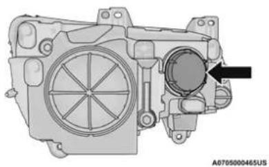
natural_image
Technical illustration of a mechanical assembly with a circular component and arrow indicating direction (no text or symbols)Turn Signal Bulb Cap
- Firmly grab the cap and rotate it counterclockwise to unlock it.
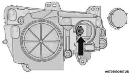
natural_image
Mechanical assembly diagram showing internal components with a highlighted section and directional arrow (no text or symbols)Turn Signal Bulb Location
- Squeeze the two tabs on the side of the bulb socket and pull straight out from the lamp assembly.
- Disconnect the bulb from the wiring connector and install the replacement bulb.
- Install the bulb and connector assembly straight into the lamp until it locks in place.
- Install the turn signal bulb cap in the headlamp housing and rotate clockwise to lock in place.
Front Fog Lamps
The Front Fog Lamps use LED sources that are not serviceable separately. The Front Fog Lamp must be replaced as an assembly; see an authorized dealer.
Front/Rear Side Marker Lamps
The Side Markers use LED lamps that are not serviceable separately. The Side Markers must be replaced as an assembly, see an authorized dealer.
Rear Backup Lamp And Turn Signal Lamps
The Rear Backup and Turn Signal Lamp use LED sources that are not serviceable separately. The Rear Lamps must be replaced as an assembly, see an authorized dealer for further information.
License Lamp
The License Lamp uses an LED source that is not serviceable separately. The License Lamp must be replaced as an assembly; see an authorized dealer.
Center High Mounted Stop Lamp (CHMSL)
The CHMSL Lamp uses LED sources that are not serviceable separately. The CHMSL Lamp must be replaced as an assembly; see an authorized dealer.
TIRES
TIRE SAFETY INFORMATION
Tire safety information will cover aspects of the following information: Tire Markings, Tire Identification Numbers, Tire Terminology and Definitions, Tire Pressures, and Tire Loading.
Tire Markings
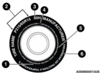
text_image
2 3 4 5 6 TIRE NAME P21695N15 95H MANUFACTURER TIRE NAME TIRE PROCEDURE A TEMPERATURE A0806000013USTire Markings
1 — US DOT Safety Standards Code (TIN)
2 — Size Designation
3 — Service Description
4 – Maximum Load
5 – Maximum Pressure
6 — Treadwear, Traction and Temperature Grades
NOTE:
- P (Passenger) — Metric tire sizing is based on US design standards. P-Metric tires have the letter "P" molded into the sidewall preceding
the size designation. Example: P215/65R1595H.
- European — Metric tire sizing is based on European design standards. Tires designed to this standard have the tire size molded into the sidewall beginning with the section width. The letter "P" is absent from this tire size designation. Example: 215/65R15 96H.
- LT (Light Truck) — Metric tire sizing is based on US design standards. The size designation for LT-Metric tires is the same as for P-Metric tires except for the letters "LT" that are molded into the sidewall preceding the size designation. Example: LT235/85R16.
- Temporary spare tires are designed for temporary emergency use only. Temporary high pressure compact spare tires have the letter "T" or "S" molded into the sidewall preceding the size designation. Example: T145/80D18 103M.
- High flotation tire sizing is based on US design standards and it begins with the tire diameter molded into the sidewall. Example: 31x10.5 R15 LT.
Tire Sizing Chart
| EXAMPLE: |
| Example Size Designation: P215/65R15XL 95H, 215/65R15 96H, LT235/85R16C, T145/80D18 103M, 31x10.5 R15 LT |
| P = Passenger car tire size based on US design standards, or |
| "....blank....." = Passenger car tire based on European design standards, or |
| LT = Light truck tire based on US design standards, or |
| T or S = Temporary spare tire or |
| 31 = Overall diameter in inches (in) |
| 215, 235, 145 = Section width in millimeters (mm) |
| 65, 85, 80 = Aspect ratio in percent (%) |
| • Ratio of section height to section width of tire, or |
| 10.5 = Section width in inches (in) |
| R = Construction code |
| • "R" means radial construction, or |
| • "D" means diagonal or bias construction |
| 15, 16, 18 = Rim diameter in inches (in) |
| Service Description: |
| 95 = Load Index |
| • A numerical code associated with the maximum load a tire can carry |
| H = Speed SymbolA symbol indicating the range of speeds at which a tire can carry a load corresponding to its load index under certain operating conditionsThe maximum speed corresponding to the speed symbol should only be achieved under specified operating conditions (i.e., tire pressure, vehicle loading, road conditions, and posted speed limits) |
| Load Identification:Absence of the following load identification symbols on the sidewall of the tire indicates a Standard Load (SL) tire:XL = Extra load (or reinforced) tire, orLL = Light load tire orC, D, E, F, G = Load range associated with the maximum load a tire can carry at a specified pressure |
| Maximum Load – Maximum load indicates the maximum load this tire is designed to carry |
| Maximum Pressure – Maximum pressure indicates the maximum permissible cold tire inflation pressure for this tire |
Tire Identification Number (TIN)
The TIN may be found on one or both sides of the tire; however, the date code may only be on one side. Tires with white sidewalls will have the full TIN, including the date code, located on the white sidewall side of the tire. Look for the TIN on the outboard side of black sidewall tires as mounted on the vehicle. If the TIN is not found on the outboard side, then you will find it on the inboard side of the tire.
| EXAMPLE: |
| DOT MA L9 ABCD 0301 |
| DOT = Department of Transportation● This symbol certifies that the tire is in compliance with the US Department of Transportation tire safety standards and is approved for highway use |
| MA = Code representing the tire manufacturing location (two digits) |
| L9 = Code representing the tire size (two digits) |
| ABCD = Code used by the tire manufacturer (one to four digits) |
| 03 = Number representing the week in which the tire was manufactured (two digits)● 03 means the 3rd week |
| 01 = Number representing the year in which the tire was manufactured (two digits)● 01 means the year 2001● Prior to July 2000, tire manufacturers were only required to have one number to represent the year in which the tire was manufactured. Example: 031 could represent the 3rd week of 1981 or 1991 |
Tire Terminology And Definitions
| Term Definition | |
| B-pillar | The vehicle B-pillar is the structural member of the body located behind the front door. |
| Cold Tire Inflation Pressure | Cold tire inflation pressure is defined as the tire pressure after the vehicle has not been driven for at least three hours, or driven less than 1 mile (1.6 km) after sitting for a minimum of three hours. Inflation pressure is measured in units of PSI (pounds per square inch) or kPa (kilopascals). |
| Maximum Inflation Pressure | The maximum inflation pressure is the maximum permissible cold tire inflation pressure for this tire. The maximum inflation pressure is molded into the sidewall. |
| Recommended Cold Tire Inflation Pressure | Vehicle manufacturer's recommended cold tire inflation pressure as shown on the tire placard. |
| Tire Placard | A label permanently attached to the vehicle describing the vehicle's loading capacity, the original equipment tire sizes and the recommended cold tire inflation pressures. |
Tire Loading And Tire Pressure
NOTE:
The proper cold tire inflation pressure is listed on the driver's side B-pillar or the rear edge of the driver's side door.
Check the inflation pressure of each tire, including the spare tire (if equipped), at least monthly and inflate to the recommended pressure for your vehicle.
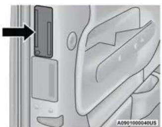
natural_image
Close-up of a door panel with a black arrow pointing to the left side (no text or symbols visible)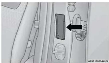
natural_image
Mechanical component diagram showing a bracket and housing assembly (no text or symbols)Example Tire Placard Location (Door) Example Tire Placard Location (B-pillar)
Tire And Loading Information Placard
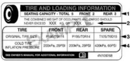
text_image
TIRE AND LOADING INFORMATION SEATING CAPACITY - TOTAL 5 FRONT 2 REAR 3 THE COMBINED WEIGHT OF OCCUPANTS AND DARGO SHOULD NEVER EXCEED XXX KG QIP XXX TBS TIRE FRONT REAR SPARE ORIGINAL TIRE SIZE P195/70R14 P195/70R14 T125/70D15 COLD TIRE INFLATION PRESSURE 200kPa, 29PSI 200kPa, 29PSI 420kPa, 60PSI SEE OWNER'S MANUAL FOR ADDITIONAL INFORMATION 4N109268Tire And Loading Information Placard
811b5a9a
This placard tells you important information about the:
- Number of people that can be carried in the vehicle.
- Total weight your vehicle can carry.
- Tire size designed for your vehicle.
- Cold tire inflation pressures for the front, rear, and spare tires.
Loading
The vehicle maximum load on the tire must not exceed the load carrying capacity of the tire on your vehicle. You will not exceed the tire's load carrying capacity if you adhere to the loading conditions, tire size, and cold tire inflation pressures specified on the Tire and Loading Information placard in "Vehicle Loading" page 132.
NOTE:
Under a maximum loaded vehicle condition, gross axle weight ratings (GAWRs) for the front and rear axles must not be exceeded.
For further information on GAWRs, vehicle loading, and trailer towing ▶ page 132.
To determine the maximum loading conditions of your vehicle, locate the statement "The combined weight of occupants and cargo should never exceed XXX kg or XXX lbs" on the Tire and Loading Information placard. The combined weight of occupants, cargo/luggage and trailer tongue weight (if applicable) should never exceed the weight referenced here.
Steps For Determining Correct Load Limit—
(1) Locate the statement "The combined weight of occupants and cargo should never exceed XXX kg or XXX lbs." on your vehicle's placard.
(2) Determine the combined weight of the driver and passengers that will be riding in your vehicle.
(3) Subtract the combined weight of the driver and passengers from XXX kg or XXX lbs.
(4) The resulting figure equals the available amount of cargo and luggage load capacity. For example, if "XXX" amount equals 1400 lbs. and there will be five 150 lb passengers in your vehicle, the amount of available cargo and luggage load capacity is 650 lbs. (1400-750 (5x150) = 650 lbs.)
(5) Determine the combined weight of luggage and cargo being loaded on the vehicle. That weight may not safely exceed the available cargo and luggage load capacity calculated in Step 4.
(6) If your vehicle will be towing a trailer, load from your trailer will be transferred to your vehicle. Consult this manual to determine how this reduces the available cargo and luggage load capacity of your vehicle.
Metric Example For Load Limit
For example, if "XXX" amount equals 635 kg and there will be five 68 kg passengers in your vehicle, the amount of available cargo and luggage load capacity is 295 kg (635-340 (5x68) = 295 kg) as shown in step 4.
NOTE:
- If your vehicle will be towing a trailer, load from your trailer will be transferred to your vehicle. The following table shows examples on how to calculate total load, cargo/luggage, and towing capacities of your vehicle with varying seating configurations and number and size of occupants. This table is for illustration purposes only and may not be accurate for the seating and load carry capacity of your vehicle.
- For the following example, the combined weight of occupants and cargo should never exceed 865 lbs (392 kg).
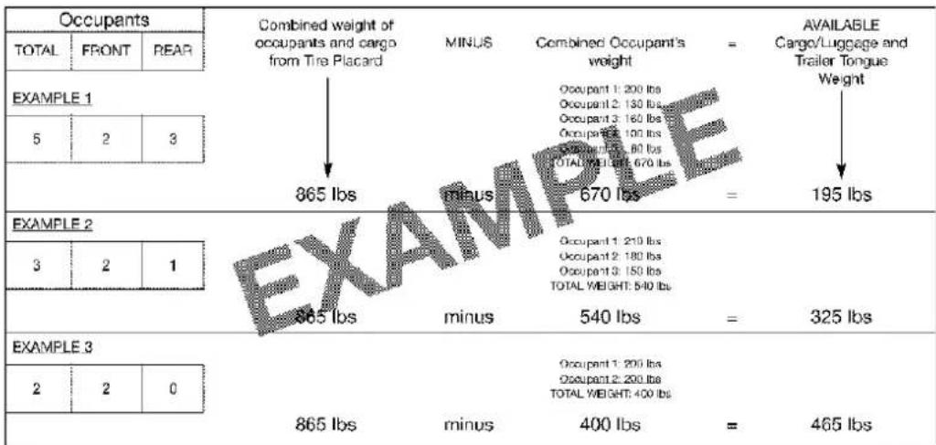
text_image
Occupants TOTAL FRONT REAR EXAMPLE 1 5 2 3 865 lbs minus 670 lbs = 195 lbs EXAMPLE 2 3 2 1 865 lbs minus 540 lbs = 325 lbs EXAMPLE 3 2 2 0 865 lbs minus 400 lbs = 465 lbs Combined weight of occupants and cargo from Tire Placard MINUS Combined Occupant's weight = AVAILABLE Cargo/Luggage and Trailer Tongue Weight511a4d11
WARNING!
Overloading of your tires is dangerous. Overloading can cause tire failure, affect vehicle handling, and increase your stopping distance. Use tires of the recommended load capacity for your vehicle. Never overload them.
TIRES — GENERAL INFORMATION
Tire Pressure
Proper tire inflation pressure is essential to the safe and satisfactory operation of your vehicle. Four primary areas are affected by improper tire pressure:
- Safety
- Fuel Economy
- Tread Wear
- Ride Comfort and Vehicle Stability
Safety Both underinflation and overinflation affect the
WARNING!
- Improperly inflated tires are dangerous and can cause collisions.
- Underinflation increases tire flexing and can result in overheating and tire failure.
- Overinflation reduces a tire's ability to cushion shock. Objects on the road and chuckholes can cause damage that result in tire failure.
- Overinflated or underinflated tires can affect vehicle handling and can fail suddenly, resulting in loss of vehicle control.
- Unequal tire pressures can cause steering problems. You could lose control of your vehicle.
- Unequal tire pressures from one side of the vehicle to the other can cause the vehicle to drift to the right or left.
● Always drive with each tire inflated to the recommended cold tire inflation pressure.
stability of the vehicle and can produce a feeling of sluggish response or over responsiveness in the steering.
NOTE:
- Unequal tire pressures from side to side may cause erratic and unpredictable steering response.
- Unequal tire pressure from side to side may cause the vehicle to drift left or right.
Fuel Economy
Underinflated tires will increase tire rolling resistance resulting in higher fuel consumption.
Tread Wear
Improper cold tire inflation pressures can cause abnormal wear patterns and reduced tread life, resulting in the need for earlier tire replacement.
Ride Comfort And Vehicle Stability
Proper tire inflation contributes to a comfortable ride. Overinflation produces a jarring and uncomfortable ride.
Tire Inflation Pressures
The proper cold tire inflation pressure is listed on the driver's side B-pillar or rear edge of the driver's side door.
At least once a month:
- Check and adjust tire pressure with a good quality pocket-type pressure gauge. Do not make a visual judgement when determining proper inflation. Tires may look properly inflated even when they are underinflated.
- Inspect tires for signs of tire wear or visible damage.
CAUTION!
After inspecting or adjusting the tire pressure, always reinstall the valve stem cap. This will prevent moisture and dirt from entering the valve stem, which could damage the valve stem.
Inflation pressures specified on the placard are always “cold tire inflation pressure”. Cold tire inflation pressure is defined as the tire pressure after the vehicle has not been driven for at least 3 hours, or driven less than 1 mile (1.6 km) after sitting for a minimum of 3 hours. The cold tire inflation pressure must not exceed the maximum inflation pressure molded into the tire sidewall.
Check tire pressures more often if subject to a wide range of outdoor temperatures, as tire pressures vary with temperature changes.
Tire pressures change by approximately 1 psi (7 kPa) per 12°F (7°C) of air temperature change. Keep this in mind when checking tire pressure inside a garage, especially in the Winter.
Example: If garage temperature = 68^ F ( 20^ C) and the outside temperature = 32^ F ( 0^ C) then the cold tire inflation pressure should be increased by 3 psi (21 kPa), which equals 1 psi (7 kPa) for every 12^ F ( 7^ C) for this outside temperature condition.
Tire pressure may increase from 2 to 6 psi (13 to 40 kPa) during operation. DO NOT reduce this normal pressure build up or your tire pressure will be too low.
Tire Pressures For High Speed Operation
The manufacturer advocates driving at safe speeds and within posted speed limits. Where speed limits or conditions are such that the vehicle can be driven at high speeds, maintaining correct tire inflation pressure is very important. Increased tire pressure and reduced vehicle loading may be required for high-speed vehicle operation. Refer to an authorized tire dealer or original equipment vehicle dealer for recommended safe operating speeds, loading and cold tire inflation pressures.
WARNING!
High speed driving with your vehicle under maximum load is dangerous. The added strain on your tires could cause them to fail. You could have a serious collision. Do not drive a vehicle loaded to the maximum capacity at continuous speeds above 75 mph (120 km/h).
Radial Ply Tires
WARNING!
Combining radial ply tires with other types of tires on your vehicle will cause your vehicle to handle poorly. The instability could cause a collision. Always use radial ply tires in sets of four. Never combine them with other types of tires.
Tire Repair
If your tire becomes damaged, it may be repaired if it meets the following criteria:
● The tire has not been driven on when flat.
- The damage is only on the tread section of your tire (sidewall damage is not repairable).
- The puncture is no greater than a 14 of an inch (6 mm).
Consult an authorized tire dealer for tire repairs and additional information.
Damaged Run Flat tires, or Run Flat tires that have experienced a loss of pressure should be replaced immediately with another Run Flat tire of identical size and service description (Load Index and Speed Symbol). Replace the tire pressure sensor as well as it is not designed to be reused.
Run Flat Tires — If Equipped
Run Flat tires allow you the capability to drive 50 miles (80 km) at 50 mph (80 km/h) after a rapid loss of inflation pressure. This rapid loss of inflation is referred to as the Run Flat mode. A Run Flat mode occurs when the tire inflation pressure is of/or below 14 psi (96 kPa). Once a Run Flat tire reaches the run flat mode it has limited driving capabilities and needs to be replaced immediately. A Run Flat tire is not repairable. When a run flat tire is changed after driving with underinflated tire condition, please replace the TPM sensor as it is not designed to be reused when driven under run flat mode 14 psi (96 kPa) condition.
NOTE:
TPM Sensor must be replaced after driving the vehicle on a flat tire condition.
It is not recommended driving a vehicle loaded at full capacity or to tow a trailer while a tire is in the run flat mode.
See the tire pressure monitoring section for more information.
Tire Spinning
When stuck in mud, sand, snow, or ice conditions, do not spin your vehicle's wheels above 30 mph (48 km/h) or for longer than 30 seconds continuously without stopping.
For further information ➤ page 224.
WARNING!
Fast spinning tires can be dangerous. Forces generated by excessive wheel speeds may cause tire damage or failure. A tire could explode and injure someone. Do not spin your vehicle's wheels faster than 30 mph (48 km/h) for more than 30 seconds continuously when you are stuck, and do not let anyone near a spinning wheel, no matter what the speed.
Tread Wear Indicators
Tread wear indicators are in the original equipment tires to help you in determining when your tires should be replaced.

text_image
① ② Tire Tread A0901000042US1 - Worn Tire
2 - New Tire
These indicators are molded into the bottom of the tread grooves. They will appear as bands when the tread depth becomes a 1/16 of an inch (1.6 mm). When the tread is worn to the tread wear indicators, the tire should be replaced.
Life Of Tire
The service life of a tire is dependent upon varying factors including, but not limited to:
- Driving style.
- Tire pressure - Improper cold tire inflation pressures can cause uneven wear patterns to develop across the tire tread. These abnormal wear patterns will reduce tread life, resulting in the need for earlier tire replacement.
- Distance driven.
- Performance tires, tires with a speed rating of V or higher, and Summer tires typically have a reduced tread life. Rotation of these tires per the vehicle scheduled maintenance is highly recommended.
WARNING!
Tires and the spare tire should be replaced after six years, regardless of the remaining tread. Failure to follow this warning can result in sudden tire failure. You could lose control and have a collision resulting in serious injury or death.
NOTE:
Wheel valve stem must be replaced as well when installing new tires due to wear and tear in existing tires.
Keep dismounted tires in a cool, dry place with as little exposure to light as possible. Protect tires from contact with oil, grease, and gasoline.
Replacement Tires
The tires on your new vehicle provide a balance of many characteristics. They should be inspected regularly for wear and correct cold tire inflation pressures. The manufacturer strongly recommends that you use tires equivalent to the originals in size, quality and performance when replacement is needed ➤ page 274. Refer to the Tire and Loading Information placard or the Vehicle Certification Label for the size designation of your tire. The Load Index and Speed Symbol for your tire will be found on the original equipment tire sidewall.
See the Tire Sizing Chart example found in the "Tire Safety Information" section of this manual for more information relating to the Load Index and Speed Symbol of a tire ➤ page 263.
It is recommended to replace the two front tires or two rear tires as a pair. Replacing just one tire can seriously affect your vehicle's handling. If you ever replace a wheel, make sure that the wheel's specifications match those of the original wheels.
It is recommended you contact an authorized tire dealer or original equipment dealer with any questions you may have on tire specifications or capability. Failure to use equivalent replacement tires may adversely affect the safety, handling, and ride of your vehicle.
WARNING!
- Do not use a tire, wheel size, load rating, or speed rating other than that specified for your vehicle. Some combinations of unapproved tires and wheels may change suspension dimensions and performance characteristics, resulting in changes to steering, handling, and braking of your vehicle. This can cause unpredictable handling and stress to steering and suspension components. You could lose control and have a collision resulting in serious injury or death. Use only the tire and wheel sizes with load ratings approved for your vehicle.
(Continued)
WARNING! (Continued)
- Never use a tire with a smaller load index or capacity, other than what was originally equipped on your vehicle. Using a tire with a smaller load index could result in tire overloading and failure. You could lose control and have a collision.
- Failure to equip your vehicle with tires having adequate speed capability can result in sudden tire failure and loss of vehicle control.
CAUTION!
Replacing original tires with tires of a different size may result in false speedometer and odometer readings.
TIRE TYPES
All Season Tires — If Equipped
All Season tires provide traction for all seasons (Spring, Summer, Autumn, and Winter). Traction levels may vary between different all season tires. All season tires can be identified by the M+S, M&S, M/S or MS designation on the tire sidewall. Use all season tires only in sets of four;
failure to do so may adversely affect the safety and handling of your vehicle.
Summer Or Three Season Tires — If Equipped
Summer tires provide traction in both wet and dry conditions, and are not intended to be driven in snow or on ice. If your vehicle is equipped with Summer tires, be aware these tires are not designed for Winter or cold driving conditions. Install Winter tires on your vehicle when ambient temperatures are less than 40^ F ( 5^ C) or if roads are covered with ice or snow. For more information, contact an authorized dealer.
Summer tires do not contain the all season designation or mountain/snowflake symbol on the tire sidewall. Use Summer tires only in sets of four; failure to do so may adversely affect the safety and handling of your vehicle.
WARNING!
Do not use Summer tires in snow/ice conditions. You could lose vehicle control, resulting in severe injury or death. Driving too fast for conditions also creates the possibility of loss of vehicle control.
Snow Tires
Some areas of the country require the use of snow tires during the Winter. Snow tires can be identified by a "mountain/snowflake" symbol on the tire sidewall.

If you need snow tires, select tires equivalent in size and type to the original equipment tires. Use snow tires only in sets of four; failure to do
so may adversely affect the safety and handling of your vehicle.
Snow tires generally have lower speed ratings than what was originally equipped with your vehicle and should not be operated at sustained speeds over 75 mph (120 km/h). For speeds above 75 mph (120 km/h) refer to original equipment or an authorized tire dealer for recommended safe operating speeds, loading and cold tire inflation pressures.
While studded tires improve performance on ice, skid and traction capability on wet or dry surfaces may be poorer than that of non-studded tires. Some states prohibit studded tires; therefore, local laws should be checked before using these tire types.
SPARE TIRES — IF EQUIPPED
CAUTION!
Because of the reduced ground clearance, do not take your vehicle through an automatic car wash with a compact or limited use temporary spare installed. Damage to the vehicle may result.
For restrictions when towing with a spare tire designated for temporary emergency use page 138.
Spare Tire Matching Original Equipped Tire And Wheel — If Equipped
Your vehicle may be equipped with a spare tire and wheel equivalent in look and function to the original equipment tire and wheel found on the front or rear axle of your vehicle. This spare tire may be used in the tire rotation for your vehicle. If your vehicle has this option, refer to an authorized tire dealer for the recommended tire rotation pattern.
Compact Spare Tire — If Equipped
The compact spare is for temporary emergency use only. You can identify if your vehicle is equipped with a compact spare by looking at the spare tire description on the Tire and Loading Information Placard located on the driver's side door opening or on the sidewall of the tire. Compact spare tire descriptions begin with the letter "T" or "S" preceding the size designation. Example: T145/80D18 103M.
T, S = Temporary Spare Tire
Since this tire has limited tread life, the original equipment tire should be repaired (or replaced) and reinstalled on your vehicle at the first opportunity.
Do not install a wheel cover or attempt to mount a conventional tire on the compact spare wheel, since the wheel is designed specifically for the compact spare tire. Do not install more than one compact spare tire and wheel on the vehicle at any given time.
WARNING!
Compact and collapsible spares are for temporary emergency use only. With these spares, do not drive more than 50 mph (80 km/h). Temporary use spares have limited tread life. When the tread is worn to the tread wear indicators, the temporary use spare tire needs to be replaced. Be sure to follow the warnings, which apply to your spare. Failure to do so could result in spare tire failure and loss of vehicle control.
Collapsible Spare Tire — If Equipped
The collapsible spare is for temporary emergency use only. You can identify if your vehicle is equipped with a collapsible spare by looking at the spare tire description on the Tire and Loading Information Placard located on the driver's side door opening or on the sidewall of the tire.
Collapsible spare tire description example: 165/80-17 101P.
Since this tire has limited tread life, the original equipment tire should be repaired (or replaced) and reinstalled on your vehicle at the first opportunity.
Inflate collapsible tire only after the wheel is properly installed to the vehicle. Inflate the collapsible tire using the electric air pump before lowering the vehicle.
Do not install a wheel cover or attempt to mount a conventional tire on the collapsible spare wheel, since the wheel is designed specifically for the collapsible spare tire.
WARNING!
Compact and Collapsible spares are for temporary emergency use only. With these spares, do not drive more than 50 mph (80 km/h). Temporary use spares have limited tread life. When the tread is worn to the tread wear indicators, the temporary use spare tire needs to be replaced. Be sure to follow the warnings, which apply to your spare. Failure to do so could result in spare tire failure and loss of vehicle control.
Full Size Spare — If Equipped
The full size spare is for temporary emergency use only. This tire may look like the originally equipped tire on the front or rear axle of your vehicle, but it is not. This spare tire may have limited tread life. When the tread is worn to the tread wear indicators, the temporary use full size spare tire needs to be replaced. Since it is not the same as your original equipment tire, replace (or repair) the original equipment tire and reinstall on the vehicle at the first opportunity.
Limited Use Spare — If Equipped
The limited use spare tire is for temporary emergency use only. This tire is identified by a label located on the limited use spare wheel. This label contains the driving limitations for this spare. This tire may look like the original equipped tire on the front or rear axle of your vehicle, but it is not. Installation of this limited use spare tire affects vehicle handling. Since it is not the same as your original equipment tire, replace (or repair) the original equipment tire and reinstall on the vehicle at the first opportunity.
WARNING!
Limited use spares are for emergency use only. Installation of this limited use spare tire affects vehicle handling. With this tire, do not drive more than the speed listed on the limited use spare wheel. Keep inflated to the cold tire inflation pressures listed on your Tire and Loading Information Placard located on the driver's side B-pillar or the rear edge of the driver's side door. Replace (or repair) the original equipment tire at the first opportunity and reinstall it on your vehicle. Failure to do so could result in loss of vehicle control.
WHEEL AND WHEEL TRIM CARE
All wheels and wheel trim, especially aluminum and chrome plated wheels, should be cleaned regularly using mild (neutral Ph) soap and water to maintain their luster and to prevent corrosion. Wash wheels with the same soap solution recommended for the body of the vehicle and remember to always wash when the surfaces are not hot to the touch.
Your wheels are susceptible to deterioration caused by salt, sodium chloride, magnesium chloride, calcium chloride, etc., and other road chemicals used to melt ice or control dust on dirt roads. Use a soft cloth or sponge and mild soap to wipe away promptly. Do not use harsh chemicals or a stiff brush. They can damage the wheel's protective coating that helps keep them from corroding and tarnishing.
CAUTION!
Avoid products or automatic car washes that use acidic solutions or strong alkaline additives or harsh brushes. Many aftermarket wheel cleaners and automatic car washes may damage the wheel's protective finish. Such damage is not covered by the New Vehicle Limited Warranty. Only car wash soap, Mopar Wheel Cleaner or equivalent is recommended.
When cleaning extremely dirty wheels including excessive brake dust, care must be taken in the selection of tire and wheel cleaning chemicals and equipment to prevent damage to the wheels. Mopar Wheel Treatment or Mopar Chrome Cleaner or their equivalent is recommended or select a non-abrasive, non-acidic cleaner for aluminum or chrome wheels.
CAUTION!
Do not use scouring pads, steel wool, a bristle brush, metal polishes or oven cleaner. These products may damage the wheel's protective finish. Such damage is not covered by the New Vehicle Limited Warranty. Only car wash soap, Mopar Wheel Cleaner or equivalent is recommended.
NOTE:
If you intend parking or storing your vehicle for an extended period after cleaning the wheels with wheel cleaner, drive your vehicle and apply the brakes to remove the water droplets from the brake components. This activity will remove the red rust on the brake rotors and prevent vehicle vibration when braking.
Dark Vapor Chrome, Black Satin Chrome, or Low Gloss Clear Coat Wheels
CAUTION!
If your vehicle is equipped with these specialty wheels, DO NOT USE wheel cleaners, abrasives, or polishing compounds. They will permanently damage this finish and such damage is not covered by the New Vehicle Limited Warranty. HAND WASH ONLY USING MILD SOAP AND WATER WITH A SOFT CLOTH. Used on a regular basis; this is all that is required to maintain this finish.
SNOW TRACTION DEVICES
Use of traction devices require sufficient tire-to-body clearance. Due to limited clearance, the following snow traction devices are recommended. Follow these recommendations to guard against damage.
■ Snow traction device must be of proper size for the tire, as recommended by the snow traction device manufacturer.
No other tire sizes are recommended for use with the snow traction device.
Please follow the table below for the recommended tire size, axle and snow traction device:
| RWDTrim Level | Axle Tire/Wheel Size | Snow Traction Device(maximum projection beyond tire profile or equivalent) | |
| Touring Rear | P215/65R17P225/60R18 | Peerless Chain Super Z6 Low Profile or Equivalent | |
| 300C NONE | |||
| 300S NONE | |||
| Limited Rear P225/60R18 | Peerless Chain Super Z6 Low Profile or Equivalent | ||
| AWDTrim Level | Axle Tire/Wheel Size | Snow Traction Device(maximum projection beyond tire profile or equivalent) | |
| Touring300SLimited | Rear | 235/55R19P235/55R19 | S Class |
WARNING!
Using tires of different size and type (M+S, Snow) between front and rear axles can cause unpredictable handling. You could lose control and have a collision.
CAUTION!
To avoid damage to your vehicle or tires, observe the following precautions:
- Because of restricted traction device clearance between tires and other suspension components, it is important that only traction devices in good condition are used. Broken devices can cause serious damage. Stop the vehicle immediately if noise occurs that could indicate device breakage. Remove the damaged parts of the device before further use.
- Install device as tightly as possible and then retighten after driving about 12 mile (0.8 km). Autosock traction devices do not require retightening.
- Do not exceed 30 mph (48 km/h).
(Continued)
CAUTION! (Continued)
- Drive cautiously and avoid severe turns and large bumps, especially with a loaded vehicle.
- Do not drive for a prolonged period on dry pavement.
- Observe the traction device manufacturer's instructions on the method of installation, operating speed, and conditions for use. Always use the suggested operating speed of the device manufacturer's if it is less than 30 mph (48 km/h).
- Do not use traction devices on a compact spare tire.
TIRE ROTATION RECOMMENDATIONS
Tires on the front and rear axles of vehicles operate at different loads and perform different steering, driving, and braking functions. For these reasons, they wear at unequal rates.
These effects can be reduced by timely rotation of tires. The benefits of rotation are especially worthwhile with aggressive tread designs such as those on all season type tires. Rotation will
increase tread life, help to maintain mud, snow and wet traction levels, and contribute to a smooth, quiet ride.
For the proper maintenance intervals. The reasons for any rapid or unusual wear should be corrected prior to rotation being performed ➤ page 228.
The suggested rotation method is the “rearward cross” shown in the following diagram. This rotation pattern does not apply to some directional tires that must not be reversed.
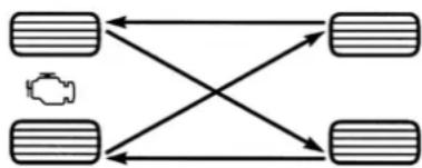
flowchart
graph TD
    A["Input 1"] --> B["Output 1"]
    C["Input 2"] --> D["Output 2"]
    E["Vehicle Icon"] --> A
    E --> C
    F["Input 3"] --> D
    F --> E
055703771
Tire Rotation (Rearward Cross)
DEPARTMENT OF TRANSPORTATION UNIFORM TIRE QUALITY GRADES
The following tire grading categories were established by the National Highway Traffic Safety Administration. The specific grade rating assigned by the tire's manufacturer in each category is shown on the sidewall of the tires on your vehicle.
All passenger vehicle tires must conform to Federal safety requirements in addition to these grades.
TREADWEAR
The Treadwear grade is a comparative rating, based on the wear rate of the tire when tested under controlled conditions on a specified government test course. For example, a tire graded 150 would wear one and one-half times as well on the government course as a tire graded 100. The relative performance of tires depends upon the actual conditions of their use, however, and may depart
significantly from the norm due to variations in driving habits, service practices, and differences in road characteristics and climate.
TRACTION GRADES
The Traction grades, from highest to lowest, are AA, A, B, and C. These grades represent the tire's ability to stop on wet pavement, as measured under controlled conditions on specified government test surfaces of asphalt and concrete. A tire marked C may have poor traction performance.
WARNING!
The traction grade assigned to this tire is based on straight-ahead braking traction tests, and does not include acceleration, cornering, hydroplaning, or peak traction characteristics.
TEMPERATURE GRADES
The Temperature grades are A (the highest), B, and C, representing the tire's resistance to the generation of heat and its ability to dissipate heat, when tested under controlled conditions on a specified indoor laboratory test wheel.
Sustained high temperature can cause the material of the tire to degenerate and reduce tire life, and excessive temperature can lead to sudden tire failure. The grade C corresponds to a level of performance, which all passenger vehicle tires must meet under the Federal Motor Vehicle Safety Standard No. 109. Grades B and A represent higher levels of performance on the laboratory test wheel, than the minimum required by law.
WARNING!
The temperature grade for this tire is established for a tire that is properly inflated and not overloaded. Excessive speed, underinflation, or excessive loading, either separately or in combination, can cause heat buildup and possible tire failure.
VEHICLE STORAGE
If you are leaving your vehicle dormant for more than 3 weeks, you may want to take these steps to protect your battery.
- Disconnect the negative cable from the battery.
- Anytime you store your vehicle, or keep it out of service (e.g., vacation) for two weeks or more, run the air conditioning system at idle for about five minutes in the fresh air and high blower setting. This will ensure adequate system lubrication to minimize the possibility of compressor damage when the system is started again.
BODYWORK
PROTECTION FROM ATMOSPHERIC AGENTS
Vehicle body care requirements vary according to geographic locations and usage. Chemicals that make roads passable in snow and ice and those that are sprayed on trees and road surfaces during other seasons are highly corrosive to the metal in your vehicle. Outside parking, which exposes your vehicle to airborne contaminants, road surfaces on which the vehicle is operated, extreme hot or cold weather and other extreme conditions will have an adverse effect on paint, metal trim, and underbody protection.
The following maintenance recommendations will enable you to obtain maximum benefit from the corrosion resistance built into your vehicle.
What Causes Corrosion?
Corrosion is the result of deterioration or removal of paint and protective coatings from your vehicle.
SERVICING AND MAINTENANCE 283
The most common causes are:
● Road salt, dirt and moisture accumulation.
• Stone and gravel impact.
• Insects, tree sap and tar.
- Salt in the air near seacoast localities.
- Atmospheric fallout/industrial pollutants.
BODY AND UNDERBODY MAINTENANCE
Cleaning Headlights
Your vehicle is equipped with plastic headlights and fog lights that are lighter and less susceptible to stone breakage than glass headlights.
Plastic is not as scratch resistant as glass and therefore different lens cleaning procedures must be followed.
To minimize the possibility of scratching the lenses and reducing light output, avoid wiping with a dry cloth. To remove road dirt, wash with a mild soap solution followed by rinsing.
Do not use abrasive cleaning components, solvents, steel wool or other aggressive material to clean the lenses.
PRESERVING THE BODYWORK
Washing
- Wash your vehicle regularly. Always wash your vehicle in the shade using Mopar Car Wash, or a mild car wash soap, and rinse the panels completely with water.
- If insects, tar, or other similar deposits have accumulated on your vehicle, use Mopar Super Kleen Bug and Tar Remover to remove.
- Use a high quality cleaner wax, such as Mopar Cleaner Wax to remove road film, stains and to protect your paint finish. Use care to never the scratch the paint.
- Avoid using abrasive compounds and power buffing that may diminish the gloss or thin out the paint finish.
CAUTION!
- Do not use abrasive or strong cleaning materials such as steel wool or scouring powder that will scratch metal and painted surfaces.
- Use of power washers exceeding 1,200 psi (8,274 kPa) can result in damage or removal of paint and decals.
Special Care
- If you drive on salted or dusty roads or if you drive near the ocean, hose off the undercarriage at least once a month.
- It is important that the drain holes in the lower edges of the doors, rocker panels, and trunk be kept clear and open.
- If you detect any stone chips or scratches in the paint, touch them up immediately.
-
If your vehicle is damaged due to a collision or similar cause that destroys the paint and protective coating, have your vehicle repaired as soon as possible.
-
If you carry special cargo such as chemicals, fertilizers, de-icer salt, etc., be sure that such materials are well packaged and sealed.
- If a lot of driving is done on gravel roads, consider mud or stone shields behind each wheel.
- Use Mopar Touch Up Paint on scratches as soon as possible. An authorized dealer has touch up paint to match the color of your vehicle.
INTERIORS
SEATS AND FABRIC PARTS
Use Mopar Total Clean to clean fabric upholstery and carpeting.
WARNING!
Do not use volatile solvents for cleaning purposes. Many are potentially flammable, and if used in closed areas they may cause respiratory harm.
Seat Belt Maintenance
Do not bleach, dye, or clean the belts with chemical solvents or abrasive cleaners. This will weaken the fabric.
If the belts need cleaning, use Mopar Total Clean, a mild soap solution, or lukewarm water. Do not remove the belts from the vehicle to wash them. Dry with a soft cloth.
Sun damage can also weaken the fabric. Replace the belts if they appear frayed or worn or if the buckles do not work properly.
WARNING!
A frayed or torn belt could rip apart in a collision and leave you with no protection. Inspect the belt system periodically, checking for cuts, frays, or loose parts. Damaged parts must be replaced immediately. Do not disassemble or modify the system. Seat belt assemblies must be replaced after a collision if they have been damaged (i.e., bent retractor, torn webbing, etc.).
PLASTIC AND COATED PARTS
Use Mopar Total Clean to clean vinyl upholstery.
CAUTION!
- Direct contact of air fresheners, insect repellents, suntan lotions, or hand sanitizers to the plastic, painted, or decorated surfaces of the interior may cause permanent damage. Wipe away immediately.
- Damage caused by these type of products may not be covered by your New Vehicle Limited Warranty.
Cleaning Plastic Instrument Cluster Lenses
The lenses in front of the instruments in this vehicle are molded in clear plastic. When cleaning the lenses, care must be taken to avoid scratching the plastic.
Clean with a wet soft cloth. A mild soap solution may be used, but do not use high alcohol content or abrasive cleaners. If soap is used, wipe clean with a clean damp cloth. Dry with a soft cloth.
LEATHER SURFACES
Mopar Total Clean is specifically recommended for leather upholstery.
Your leather upholstery can be best preserved by regular cleaning with a damp soft cloth. Small particles of dirt can act as an abrasive and damage the leather upholstery and should be removed promptly with a damp cloth. Stubborn soils can be removed easily with a soft cloth and Mopar Total Clean. Care should be
taken to avoid soaking your leather upholstery with any liquid. Please do not use polishes, oils, cleaning fluids, solvents, detergents, or ammonia-based cleaners to clean your leather upholstery.
NOTE:
If equipped with light colored leather, it tends to show any foreign material, dirt, and fabric dye transfer more so than darker colors. The leather is designed for easy cleaning, and FCA recommends Mopar total care leather cleaner applied on a cloth to clean the leather seats as needed.
CAUTION!
Do not use Alcohol and Alcohol-based and/or Ketone based cleaning products to clean leather seats, as damage to the seat may result.
GLASS SURFACES
All glass surfaces should be cleaned on a regular basis with Mopar Glass Cleaner, or any commercial household-type glass cleaner. Never use an abrasive type cleaner. Use caution when cleaning the inside rear window equipped with electric defrosters or windows equipped with radio antennas. Do not use scrapers or other sharp instruments that may scratch the elements.
When cleaning the rear view mirror, spray cleaner on the towel or cloth that you are using. Do not spray cleaner directly on the mirror.
TECHNICAL SPECIFICATIONS
VEHICLE IDENTIFICATION NUMBER (VIN)
The VIN is on the left front corner of the instrument panel. The VIN is visible from outside of the vehicle through the windshield.
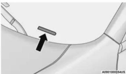
natural_image
Medical illustration showing a surgical tool interacting with a patient's arm (no text or symbols present)Windshield VIN Location
NOTE:
It is illegal to remove or alter the VIN.
BRAKE SYSTEM
Your vehicle is equipped with dual hydraulic brake systems. If either of the two hydraulic systems loses normal capability, the remaining system will still function. There will be some loss of overall braking effectiveness. This may be evident by increased pedal travel during application, greater pedal force required to slow or stop, and potential activation of the Brake Warning Light.
In the event power assist is lost for any reason (for example, repeated brake applications with the engine OFF), the brakes will still function. The effort required to brake the vehicle will be much greater than that required with the power system operating.
WHEEL AND TIRE TORQUE SPECIFICATIONS
Proper lug nut/bolt torque is very important to ensure that the wheel is properly mounted to the vehicle. Any time a wheel has been removed and reinstalled on the vehicle, the lug nuts/bolts should be torqued using a properly calibrated torque wrench using a high quality six sided (hex) deep wall socket.
TORQUE SPECIFICATIONS
| Lug Nut/Bolt Torque | **Lug Nut/ Bolt Size | Lug Nut/Bolt Socket Size |
| 130 Ft-Lbs (176 N·m) | M14 x 1.50 22 | mm |
**Use only authorized dealer recommended lug nuts/bolts and clean or remove any dirt or oil before tightening.
Inspect the wheel mounting surface prior to mounting the tire and remove any corrosion or loose particles.
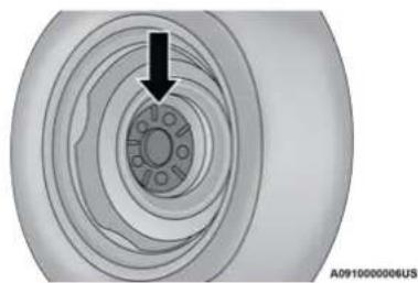
natural_image
Close-up of a mechanical component with concentric rings and a small inset showing a black arrow pointing to a circular feature (no text or symbols)Wheel Mounting Surface
Tighten the lug nuts/bolts in a star pattern until each nut/bolt has been tightened twice. Ensure that the socket is fully engaged on the lug nut/bolt (do not insert it halfway).
NOTE:
If in doubt about the correct tightness, have them checked with a torque wrench by an authorized dealer or service station.
After 25 miles (40 km), check the lug nut/bolt torque to be sure that all the lug nuts/bolts are properly seated against the wheel.
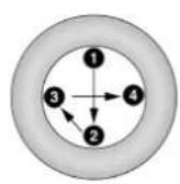

A0910000005US
Torque Patterns
WARNING!
To avoid the risk of forcing the vehicle off the jack, do not tighten the lug nuts/bolts fully until the vehicle has been lowered. Failure to follow this warning may result in personal injury.
FUEL REQUIREMENTS
While operating on gasoline with the required octane number, hearing a light knocking sound from the engine is not a cause for concern. However, if the engine is heard making a heavy knocking sound, see a dealer immediately. Use of gasoline with a lower than recommended octane number can cause engine failure and may void the New Vehicle Limited Warranty.
Poor quality gasoline can cause problems such as hard starting, stalling, and hesitations. If you experience these symptoms, try another brand of gasoline before considering service for the vehicle.
3.6L ENGINE
87
This engine is designed to meet all emissions regulations and provide excellent fuel economy and performance when using high-quality
unleaded "regular" gasoline having an octane rating of 87 as specified by the (R + M) / 2 method. The use of higher octane "premium" gasoline will not provide any benefit over "regular" gasoline in these engines.
5.7L ENGINE
Do not use E-85 flex fuel or ethanol blends greater than 15% in this engine.
89
This engine is designed to meet all emissions regulations and provide satisfactory fuel economy and performance when using high-quality
unleaded gasoline having an octane range of 87 to 89 as specified by the (R+M)/2 method. The use of 89 octane “plus” gasoline is recommended for optimum performance and fuel economy.
REFORMULATED GASOLINE
Many areas of the country require the use of cleaner burning gasoline referred to as “reformulated gasoline”. Reformulated gasoline contains oxygenates and are specifically blended to reduce vehicle emissions and improve air quality.
The use of reformulated gasoline is recommended. Properly blended reformulated gasoline will provide improved performance and durability of engine and fuel system components.
MATERIALS ADDED TO FUEL
Besides using unleaded gasoline with the proper octane rating, gasolines that contain detergents, corrosion and stability additives are recommended. Using gasolines that have these additives will help improve fuel economy, reduce emissions, and maintain vehicle performance.

Designated TOP TIER Detergent Gasoline contains a higher level of detergents to further aide in minimizing engine and fuel system
deposits. When available, the usage of TOP TIER Detergent Gasoline is recommended. Visit
www.toptiergas.com for a list of TOP TIER Detergent Gasoline Retailers.
Indiscriminate use of fuel system cleaning agents should be avoided. Many of these materials intended for gum and varnish removal may contain active solvents or similar ingredients. These can harm fuel system gasket and diaphragm materials.
GASOLINE/OXYGENATE BLENDS
Some fuel suppliers blend unleaded gasoline with oxygenates such as ethanol.
CAUTION!
DO NOT use E-85, gasoline containing methanol, or gasoline containing more than 15% ethanol (E-15). Use of these blends may result in starting and drivability problems, damage critical fuel system components, cause emissions to exceed the applicable standard, and/or cause the Malfunction Indicator Light to illuminate. Please observe pump labels as they should clearly communicate if a fuel contains greater than 15% ethanol (E-15).
Problems that result from using gasoline containing more than 15% ethanol (E-15) or gasoline containing methanol are not the responsibility of the manufacturer and may void or not be covered under New Vehicle Limited Warranty.
Do Not Use E-85 IN Non-FLEX FUEL VEHICLES
Non-Flex Fuel Vehicles (FFV) are compatible with gasoline containing up to 15% ethanol (E-15). Use of gasoline with higher ethanol content may void the New Vehicle Limited Warranty.
If a Non-FFV vehicle is inadvertently fueled with E-85 fuel, the engine will have some or all of these symptoms:
- Operate in a lean mode.
- OBD II Malfunction Indicator Light on.
- Poor engine performance.
● Poor cold start and cold drivability. - Increased risk for fuel system component corrosion.
CNG AND LP FUEL SYSTEM MODIFICATIONS
Modifications that allow the engine to run on Compressed Natural Gas (CNG) or Liquid Propane (LP) may result in damage to the engine, emissions, and fuel system components. Problems that result from running CNG or LP are not the responsibility of the manufacturer and may void or not be covered under the New Vehicle Limited Warranty.
METHYLCYCLOPENTADIENYL MANGANESE TRICARBONYL (MMT) IN GASOLINE
MMT is a manganese-containing metallic additive that is blended into some gasoline to increase octane. Gasoline blended with MMT provides no performance advantage beyond gasoline of the same octane number without MMT. Gasoline blended with MMT reduces spark plug life and reduces emissions system performance in some vehicles. The manufacturer recommends that gasoline without MMT be used in your vehicle. The MMT content of gasoline may not be indicated on the gasoline pump; therefore, you should ask your gasoline retailer whether the gasoline contains MMT. MMT is prohibited in Federal and California reformulated gasoline.
FUEL SYSTEM CAUTIONS
CAUTION!
Follow these guidelines to maintain your vehicle's performance:
- The use of leaded gasoline is prohibited by Federal law. Using leaded gasoline can impair engine performance and damage the emissions control system.
- An out-of-tune engine or certain fuel or ignition malfunctions can cause the catalytic converter to overheat. If you notice a pungent burning odor or some light smoke, your engine may be out of tune or malfunctioning and may require immediate service. Contact an authorized dealer for service assistance.
(Continued)
CAUTION! (Continued)
- The use of fuel additives, which are now being sold as octane enhancers, is not recommended. Most of these products contain high concentrations of methanol. Fuel system damage or vehicle performance problems resulting from the use of such fuels or additives is not the responsibility of the manufacturer and may void or not be covered under the New Vehicle Limited Warranty.
NOTE:
Intentional tampering with the emissions control system can result in civil penalties being assessed against you.
FLUID CAPACITIES
| US Metric | ||
| Fuel (Approximate) | ||
| All Engines 18.5 Gallons 70 Liters | ||
| Engine Oil With Filter | ||
| 3.6L Engine 6 Quarts 5.6 Liters | ||
| 5.7L Engine 7 Quarts 6.6 Liters | ||
| Cooling System* | ||
| 3.6L Engine 10 Quarts 9.5 Liters | ||
| 5.7L Engine – without Severe Duty II Cooling System 14.5 Quarts 13.9 Liters | ||
| 5.7L Engine – with Severe Duty II Cooling System 15 Quarts 14.3 Liters | ||
| * Includes heater and coolant recovery bottle filled to MAX level. | ||
ENGINE FLUIDS AND LUBRICANTS
| Component Fluid, Lubricant, or Genuine Part | |
| Engine Coolant | We recommend you use Mopar Antifreeze/Coolant 10 Year/150,000 Mile (240,000 km) Formula OAT (Organic Additive Technology). |
| Engine Oil | We recommend you use API Certified SAE 5W-20 Engine Oil, meeting the requirements of FCA Material Standard MS-6395 such as Mopar, Pennzoil, and Shell Helix Ultra. Refer to your engine oil filler cap for correct SAE grade. |
292 TECHNICAL SPECIFICATIONS
| Component Fluid, Lubricant, or Genuine Part | |
| Engine Oil Filter | We recommend you use a Mopar Engine Oil Filter. If a Mopar Engine Oil Filter is unavailable only use filters that meet or exceed SAE/USCAR-36 Filter Performance Requirements. |
| Fuel Selection - 3.6L Engine 87 Octane (R+M)/2 method, 0-15% ethanol. | |
| Fuel Selection - 5.7L Engine | 89 Octane Recommended - 87 Octane Acceptable (R+M)/2 method, 0-15% ethanol. |
CAUTION!
- Mixing of engine coolant (antifreeze) other than specified Organic Additive Technology (OAT) engine coolant (antifreeze), may result in engine damage and may decrease corrosion protection. Organic Additive Technology (OAT) engine coolant is different and should not be mixed with Hybrid Organic Additive Technology (HOAT) engine coolant (antifreeze) or any “globally compatible” coolant (antifreeze). If a non-OAT engine coolant (antifreeze) is introduced into the cooling system in an emergency, the cooling system will need to be drained, flushed, and refilled with fresh OAT coolant (conforming to MS.90032), by an authorized dealer as soon as possible.
CAUTION! (Continued)
- Do not use water alone or alcohol-based engine coolant (antifreeze) products. Do not use additional rust inhibitors or antirust products, as they may not be compatible with the radiator engine coolant and may plug the radiator.
(Continued)
CAUTION! (Continued)
- This vehicle has not been designed for use with propylene glycol-based engine coolant (antifreeze). Use of propylene glycol-based engine coolant (antifreeze) is not recommended.
(Continued)
CHASSIS FLUIDS AND LUBRICANTS
| Component Fluid, Lubricant, Or Genuine Part | |
| Automatic Transmission | Use only Mopar ZF 8&9 Speed ATF Automatic Transmission Fluid, or equivalent. Failure to use the correct fluid may affect the function or performance of your transmission. |
| Brake Master Cylinder We recommend you use Mopar DOT 3 and SAE J1703. | |
| Front Axle - AWD (If Equipped) | We recommend you use Mopar Synthetic Gear Lubricant SAE 75W90 (API GL-5). |
| Rear Axle | We recommend you use Mopar OD Synthetic Gear Lubricant SAE 75W85 (API GL-5). |
| Transfer Case - AWD (If Equipped) | We recommend you use Mopar Transfer Case Lubricant for BorgWarner 44–40. |
CUSTOMER ASSISTANCE
SUGGESTIONS FOR OBTAINING SERVICE FOR YOUR VEHICLE
PREPARE FOR THE APPOINTMENT
All work to be performed may not be covered by the warranty. Discuss additional charges with the service manager. Keep a maintenance log of your vehicle's service history. This can often provide a clue to the current problem.
PREPARE A LIST
Make a written list of your vehicle's problems or the specific work you want done. If you've had an accident or work done that is not on your maintenance log, let the service advisor know.
BE REASONABLE WITH REQUESTS
If you list a number of items and you must have your vehicle by the end of the day, discuss the situation with the service advisor and list the items in order of priority. At many authorized dealers, you may obtain a rental vehicle
(additional charges may apply). If you need a rental, it is advisable to make these arrangements when you call for an appointment.
IF YOU NEED ASSISTANCE
FCA US LLC and its authorized dealers are vitally interested in your satisfaction. We want you to be happy with our products and services.
Warranty service must be done by an authorized dealer. We strongly recommend that you take the vehicle to an authorized dealer. They know your vehicle the best, and are most concerned that you get prompt and high quality service. FCA US LLC's authorized dealers have the facilities, factory-trained technicians, special tools, and the latest information to ensure the vehicle is fixed correctly and in a timely manner.
This is why you should always talk to an authorized dealer's service manager first. If for some reason you are still not satisfied, talk to the general manager or owner of the authorized dealer. They want to know if you need assistance. If an authorized dealer is unable to resolve the concern, you may contact FCA US LLC's Customer Assistance center.
Any communication to FCA US LLC's customer center should include the following information:
- Owner's name and address
- Owner's telephone number (home, mobile, and office)
- Authorized dealer name
• Vehicle Identification Number (VIN)
● Vehicle delivery date and mileage
FCA US LLC C USTOMER CENTER
P.O. Box 21-8004
Auburn Hills, MI 48321-8004
Phone: (800) 247-9753
FCA CANADA INC. CUSTOMER CENTER
P.O. Box 1621
Windsor, Ontario N9A 4H6
Phone: (800) 465-2001 English /
(800) 387-9983 French
MEXICO
In Mexico City: 800-505-1300
Outside Mexico City: +(52)55 50817568
PUERTO RICO AND US VIRGIN ISLANDS
FCA Caribbean LLC
P.O. Box 191857
San Juan 00919-1857
Phone: (800) 247-9753
Fax: (787) 782-3345
CUSTOMER ASSISTANCE FOR THE HEARING OR SPEECH IMPAIRED (TDD/TTY)
To assist customers who have hearing difficulties, the FCA US LLC has installed special TDD (Telecommunication Devices for the Deaf) equipment at its customer center. Any hearing or speech impaired customer, who has access to a TDD or a conventional teletypewriter (TTY) in the United States, can communicate with the FCA US LLC by dialing 1-800-380-2479.
Canadian residents with hearing difficulties that require assistance can use the special needs relay service offered by Bell Canada. For TTY teletypewriter users, dial 711 and for Voice callers, dial 1-800-855-0511 to connect with a Bell Relay Service operator.
SERVICE CONTRACT
You may have purchased a service contract for a vehicle to help protect you from the high cost of unexpected repairs after FCA US LLC's New Vehicle Limited Warranty expires. The Mopar Vehicle Protection plans are the ONLY vehicle extended protection plans authorized, endorsed and backed by FCA US LLC to provide additional protection beyond your vehicle's warranty. If you purchased a Mopar Vehicle Protection Plan, you will receive Plan Provisions and an Owner Identification Card in the mail within three weeks of the vehicle delivery date. If you have any questions about the service contract, call the FCA US LLC's Service Contract National Customer Hotline at 1-800-521-9922 (Canadian residents, call (800) 465-2001 English / (800) 387-9983 French).
FCA US LLC is not responsible for any service contract you may have purchased from another manufacturer. If you require service after the FCA US LLC New Vehicle Limited Warranty expires, please refer to the contract documents, and contact the person listed in those documents.
We appreciate that you have made a major investment when you purchased the vehicle. An authorized dealer has also made a major investment in facilities, tools, and training to assure that you are absolutely delighted with the ownership experience.
WARNING!
Engine exhaust (internal combustion engines only), some of its constituents, and certain vehicle components contain, or emit, chemicals known to the State of California to cause cancer and birth defects, or other reproductive harm. In addition, certain fluids contained in vehicles and certain products of component wear contain, or emit, chemicals known to the State of California to cause cancer and birth defects, or other reproductive harm.
WARRANTY INFORMATION
See the Warranty Information for the terms and provisions of FCA US LLC warranties applicable to this vehicle and market. Refer to www.mopar.com/om for further information. See the Warranty Information for the terms and provisions of FCA Canada Inc. warranties applicable to this vehicle and market. Refer to www.owners.mopar.ca/en for further information.
Use this QR code to access your digital experience.
MOPAR PARTS
Mopar original equipment parts & accessories and factory filled fluids are available from an authorized dealer. They are recommended for your vehicle to keep it operating at its best and maintain its original condition.
REPORTING SAFETY DEFECTS
IN THE 50 UNITED STATES AND WASHINGTON, D.C.
If you believe that your vehicle has a defect that could cause a crash or cause injury or death, you should immediately inform the National Highway Traffic Safety Administration (NHTSA) in addition to notifying FCA US LLC.
If NHTSA receives similar complaints, it may open an investigation, and if it finds that a safety defect exists in a group of vehicles, it may order a recall and remedy campaign. However, NHTSA cannot become involved in individual problems between you, an authorized dealer or FCA US LLC.
To contact NHTSA, you may call the Vehicle Safety Hotline toll free at 1-888-327-4236 (TTY:
1-800-424-9153); or go to http://www.safercar.gov; or write to: Administrator, NHTSA, 1200 New Jersey Avenue, SE., West Building, Washington, D.C. 20590. You can also obtain other information about motor vehicle safety from http://www.safercar.gov.
IN CANADA
If you believe that your vehicle has a safety defect, you should contact the Customer Service Department immediately. Canadian customers who wish to report a safety defect to the Canadian government should contact Transport Canada, Motor Vehicle Defect Investigations and Recalls at 1-800-333-0510 or go to wwwapps.tc.gc.ca/Saf-Sec-Sur/7/PCDB-BDPP.
PUBLICATION ORDER FORMS
To order the following manuals, you may use either the website or the phone numbers listed below.
Service Manuals
These comprehensive Service Manuals provide a complete working knowledge of the vehicle, system, and/or components and is written in straightforward language with illustrations, diagrams, and charts.
Diagnostic Procedure Manuals
Diagnostic Procedure Manuals are filled with diagrams, charts and detailed illustrations. These manuals make it easy to find and fix problems on computer-controlled vehicle systems and features. They show exactly how to find and correct problems, using step-by-step troubleshooting and drivability procedures, proven diagnostic tests and a complete list of all tools and equipment.
Owner's Manuals
These Owner's Manuals have been prepared with the assistance of service and engineering specialists to acquaint you with specific FCA US LLC vehicles.
To access your Owner's Information online, visit www.mopar.com/om
To order a hard copy of your Owner's Information, visit:
• www.techauthority.com (US)
Or
Call Tech Authority toll free at:
• 1-800-890-4038 (US)
• 1-800-387-1143 (Canada)
GENERAL INFORMATION
The following regulatory statement applies to all Radio Frequency (RF) devices equipped in this vehicle:
This device complies with Part 15 of the FCC Rules and with Innovation, Science and Economic Development Canada license-exempt RSS standard(s). Operation is subject to the following two conditions:
-
This device may not cause harmful interference, and
-
This device must accept any interference received, including interference that may cause undesired operation.
Changes or modifications not expressly approved by the party responsible for compliance could void the user's authority to operate the equipment.
INDEX
WARRANTY INFORMATION ......296
A
About Your Brakes....287
Adaptive Cruise Control (ACC)
(Cruise Control)....109
Adding Engine Coolant (Antifreeze) ......244
Adding Fuel 131
Adding Washing Fluid 234
Additives, Fuel 289
Adjust
Forward 32
Rearward.... 32
Air Bag 185
Advance Front Air Bag 185
Air Bag Operation ....186
Air Bag Warning Light 184
Driver Knee Air Bag 187
Enhanced Accident Response ..... 191, 227
Event Data Recorder (EDR) 227
Front Air Bag 185
If Deployment Occurs ....190
Knee Impact Bolsters ....187
Maintaining Your Air Bag System 192
Maintenance 192
Redundant Air Bag Warning Light 185
Side Air Bags 187
Transporting Pets 206
Air Bag Light 82,184,206
Air Cleaner, Engine
(Engine Air Cleaner Filter) 237
Air Conditioner Maintenance 237
Air Conditioner Refrigerant 237, 238
Air Conditioner System ....53, 237
Air Conditioning Filter 58,238
Air Conditioning, Operating Tips ....57
Air Filter 237
Air Pressure
Tires 272
Alarm
Arm The System 20, 21
Rearm The System 21
Security Alarm 20,85
Alarm System
Security Alarm 20
All Wheel Drive
Towing 226
All Wheel Drive (AWD) 248
Alterations/Modifications
Vehicle 8
Antifreeze (Engine Coolant) 243, 291
Disposal 245
Anti-Lock Brake System (ABS) 159
Anti-Lock Warning Light 86
Arming System
Security Alarm 20
Assist, Hill Start 164
Audio Systems (Radio) 143
Auto Down Power Windows 65
Automatic Door Locks 25
Automatic Headlights ....47
Automatic High Beams 46
Automatic Temperature Control (ATC) .....56
Automatic Transmission 100
Adding Fluid 247, 293
Fluid And Filter Change 247
Fluid Change 247
Fluid Level Check 247
Fluid Type 247, 293
Special Additives 247
Automatic Transmission
Limp Home Mode 25, 104
AutoPark 95
Autostick
Operation 104
AUX Cord.... 61
Auxiliary Electrical Outlet (Power Outlet) 63
AWD
Towing 226
Axle Fluid 293
Axle Lubrication 293
B
Back-Up 129
Battery 83,234
Charging System Light 83
Keyless Key Fob Replacement 13
Location 234
Belts, Seat 206
Beverage Holder Cooled (Cupholder) 62
Beverage Holder Heated (Cupholder) 62
Body Mechanism Lubrication ....239
B-Pillar Location 267
Brake Assist System 160
Brake Control System 160
Brake Fluid 246, 293
Brake System 246, 287
Fluid Check 246, 293
Master Cylinder 246
Parking 98
Warning Light 82,287
Brake/Transmission Interlock 100
Break-In Recommendations, New Vehicle .....97
Brightness, Interior Lights 50
Bulb Replacement 259
Bulbs, Light 208, 259
C
Camera, Rear 129
Capacities, Fluid 291
Caps, Filler
Oil (Engine) 232
Radiator (Coolant Pressure) 244
Car Washes.... 284
Carbon Monoxide Warning 209
Cargo
Vehicle Loading 132
Cargo Area Cover 71
Cargo Compartment ....71
Cellular Phone 158
Certification Label 133
Chains, Tire 280
Chart, Tire Sizing 264
Check Engine Light (Malfunction
Indicator Light) 91
Checking Your Vehicle For Safety 206
Checks, Safety 206
Child Restraint 193
Child Restraints
Booster Seats 196
Child Seat Installation 203
How To Stow An unused ALR Seat Belt ..... 201
Infant And Child Restraints 195
Lower Anchors And Tethers For Children .. 198
Older Children And Child Restraints ..... 195
Seating Positions 197
Child Safety Locks 25
Clean Air Gasoline 289
Cleaning
Wheels 278
Climate Control ....53
Automatic 53
Coin Holder 59
Cold Weather Operation 96
Compact Spare Tire 276
Console
Floor 59
Contract, Service 295
Cooling Pressure Cap (Radiator Cap) 244
Cooling System....243
Adding Coolant (Antifreeze) 244
Coolant Capacity 291
Coolant Level 243, 245
Disposal Of Used Coolant 245
Drain, Flush, And Refill 243
Inspection 245
Points To Remember 245
Pressure Cap 244
Radiator Cap 244
Selection Of Coolant (Antifreeze) ..... 243, 291
Corrosion Protection 283
Cruise Control (Speed Control) 107, 109
Cruise Light 89,90
Customer Assistance 294
Cybersecurity 143
D
Daytime Running Lights 46
Dealer Service 235
Deck Lid
Power Release 69
Defroster, Windshield ....207
Diagnostic System, Onboard 90
Dimmer Switch
Headlight 46
Dipsticks
Oil (Engine) 234
Disable Vehicle Towing 225
Disposal
Antifreeze (Engine Coolant) 245
Door Ajar 84
Door Ajar Light 84
Door Locks
Automatic 25
Child-Protection Door Lock — Rear Doors ....25
Doors 21
Driver's Seat Back Tilt 30
Driving
Through Flowing, Rising, Or Shallow
Standing Water 141
E
Electric Brake Control System.... 160
Anti-Lock Brake System 159
Electronic Roll Mitigation 161, 165
Electric Remote Mirrors 39
Electronic Power Distribution Center (Fuses) ...249
Electronic Speed Control (Cruise Control) ..... 108
Electronic Stability Control (ESC) 161
Electronic Throttle Control Warning Light ......84
Emergency Gas Can Refueling 221
Emergency, In Case Of
Freeing Vehicle When Stuck 224
Hazard Warning Flasher 210
Jacking 214
Jump Starting 218
Towing 225
Emission Control System Maintenance .....91
Engine 232,233
Air Cleaner 237
Block Heater 97
Break-In Recommendations .....97
Checking Oil Level 234
Compartment 232, 233
Compartment Identification 232
Coolant (Antifreeze) 243, 291
Cooling....243
Exhaust Gas Caution 209
Fails To Start 96
Flooded, Starting 96
Fuel Requirements 288
Jump Starting 218
Oil 236,291
Oil Filler Cap 232
Oil Filter 236
Oil Selection 236, 291
Oil Synthetic 236
Overheating 222
Starting....93,94
Enhanced Accident Response Feature ... 191, 227
Ethanol....289
Exhaust Gas Cautions 209
Exhaust System 209, 241
Exterior Lighting 45
Exterior Lights 45,208
F
Filters
Air Cleaner....237
Air Conditioning 58,238
Engine Oil 236, 291
Engine Oil Disposal 236
Flashers....210
Hazard Warning 210
Turn Signals 49,89,208
Flash-To-Pass 47
Flooded Engine Starting 96
Floor Console 59
Fluid Capacities 291
Fluid Leaks 208
Fluid Level Checks
Brake 246
Cooling System 243
Engine Oil 234
Transfer Case 248
Fluid, Brake 293
Fog Lights 48
Fold-Flat Seats 30
Folding Rear Seats 31
Forward Collision Warning ....170
Four-Way Hazard Flasher 210
Freeing A Stuck Vehicle 224
Fuel....288
Additives 289
Clean Air 289
Ethanol 289
Gasoline 288
Gauge 87
Materials Added 289
Methanol 289
Octane Rating 288, 291
Requirements 288
Specifications 291
Tank Capacity 291
Fuses 248
G
Garage Door Opener (HomeLink) ....41
Gasoline, Clean Air 289
Gasoline, Reformulated 289
Gauges
Fuel 87
Gear Ranges 101
Glass Cleaning 286
Gross Axle Weight Rating 133, 134
Gross Vehicle Weight Rating 133, 134
GVWR.... 133
H
Hazard
Driving Through Flowing, Rising,
Or Shallow Standing Water.... 141
Hazard Warning Flashers 210
Head Restraints 36,37
Head Rests 36,37
Headlights 261
Automatic 47
Cleaning.... 283
High Beam/Low Beam Select Switch .....46
Lights On Reminder 48
On With Wipers 47
Passing 47
Switch 45
Time Delay 48
Washers.... 234
Heated Mirrors 41
Heated Seats 34
Heater, Engine Block 97
High Beam/Low Beam Select (Dimmer) Switch .. 46
Hill Start Assist 164
Hitches
Trailer Towing 136
Holder, Coin ....59
HomeLink (Garage Door Opener) 41
Hood Prop 69
Hood Release 69
|
Ignition 15
Switch 15
Inside Rearview Mirror 38, 210
Instrument Cluster .... 73, 75 Descriptions .... 89 Display .... 75, 78
Instrument Panel Lens Cleaning .....286
Interior Appearance Care ....284
Interior Lights 49
J
Jack Location....214
Jack Operation 215
Jacking Instructions 215
Jump Starting 218
K
Key Fob Arm The System 20 Unlatch The Trunk 13
Key Fob Battery Service (Remote Keyless Entry) 13
Keyless Enter-N-Go ....22, 93 Enter The Trunk ....13 Passive Entry ....22 Passive Entry Programming ....22
Keys....12 Replacement....14
L
Lane Change And Turn Signals ....49
Lane Change Assist ....49
LaneSense 127
Lap/Shoulder Belts 178
Latches 208 Hood 69
Lead Free Gasoline 288
Leaks, Fluid 208
Life Of Tires 274
Light Bulbs 208, 259
Lights 208 Air Bag 82,184,206
Automatic Headlights ....47
Brake Assist Warning 163
Brake Warning 82, 287
Bulb Replacement 259
Cruise 89,90
Daytime Running 46
Dimmer Switch, Headlight 46
Engine Temperature Warning 84
Exterior 208
Fog 48
Hazard Warning Flasher 210
Headlight Switch 45
Headlights 45, 48, 261
Headlights On With Wipers 47
High Beam 46
High Beam/Low Beam Select 46
Instrument Cluster 45
Intensity Control ....50
Interior 49
License 263
Lights On Reminder 48
Malfunction Indicator (Check Engine) .....87
Map 49
Park 47,89
Passing 47
Reading 49
Seat Belt Reminder 83
Security Alarm 85
Service.... 259
Traction Control 163
Turn Signals 46, 49, 89, 208
Vanity Mirror 38
Warning Instrument Cluster Descriptions....84, 89
Load Leveling System 72
Load Shed Battery Saver On 81
Load Shed Electrical Load Reduction .....81
Load Shed Intelligent Battery Sensor 81
Loading Vehicle 132, 133
Capacities 133
Tires....267
Locks
Auto Unlock 25
Automatic Door 25
Child Protection 25
Power Door....22
Low Tire Pressure System 172
Lubrication, Body 239
Lug Nuts 287
M
Maintenance Free Battery 234
Maintenance Schedule 228, 229
Malfunction Indicator Light (Check Engine) ..... 87
Manual
Park Release....222
Service 297
Media Hub 61
Memory Feature (Memory Seats) 30
Memory Seat 30
Memory Seats And Radio 30
Methanol 289
Mirrors 38
Electric Powered 39
Electric Remote 39
Heated 41
Outside....39
Rearview 38,210
Vanity 38
Modifications/Alterations
Vehicle....8
Monitor, Tire Pressure System 172
Mopar Parts 296
MP3 Control 61
Multi-Function Control Lever 46
N
New Vehicle Break-In Period 97
0
Occupant Restraints 176
Octane Rating, Gasoline (Fuel) 288, 291
Oil Change Indicator 77
Reset 77
Oil Filter, Change 236
Oil Filter, Selection 236
Oil Pressure Light 85
Oil, Engine.... 236, 291
Capacity.... 291
Checking.... 234
Dipstick 234
Disposal 236
Filter 236,291
Filter Disposal 236
Identification Logo 236
Materials Added To 236
Pressure Warning Light 85
Recommendation 236, 291
Synthetic.... 236
Viscosity.... 291
Onboard Diagnostic System 90
Operating Precautions 90
Operator Manual
Owner's Manual 297
Outside Rearview Mirrors 39
Overheating, Engine 222
P
Paddle Shift Mode 104
Paddle Shifters 104
Paint Care 283
Parking Brake 98
ParkSense System, Rear 120
Passive Entry....22
Pets....206
Placard, Tire And Loading Information ..... 267
Power
Brakes 287
Deck Lid Release 69
Distribution Center (Fuses) 254
Door Locks....22
Mirrors 39
Outlet (Auxiliary Electrical Outlet) 63
Seats......32
Steering....106
Sunroof 67
Tilt/Telescoping Steering Column 26
Windows.... 65
Power Seats
Forward 32
Lumbar.... 33
Rearward.... 32
Recline 32
Pregnant Women And Seat Belts ....182
Preparation For Jacking 214
Pretensioners
Seat Belts 182
R Radial Ply Tires....273
Radiator Cap (Coolant Pressure Cap) ......244
Radio Operation 158
Rain Sensitive Wiper System 52
Rear Axle (Differential) 248
Rear Camera 129
Rear Cross Path 168
Rear ParkSense System 120
Rear Seats, Folding 31
Rear Wheel Drive (RWD)
Towing....226
Recreational Towing 140
Reformulated Gasoline 289
Refrigerant 237, 238
Release, Hood ....69
Reminder, Lights On ....48
Reminder, Seat Belt 177
Remote Keyless Entry Arm The Alarm....20
Unlatch The Trunk 13
Remote Starting Exit Remote Start Mode ....18
Uconnect Customer Programmable Features ....19
Uconnect Settings ....19
Remote Trunk Release 69
Replacement Bulbs 259
Replacement Keys 14
Replacement Tires 274
Reporting Safety Defects 296
Restraints, Child 193
Restraints, Head 36, 37
Rocking Vehicle When Stuck 224
Rotation, Tires 281
S Safety Checks Inside Vehicle 206
Safety Checks Outside Vehicle 208
Safety Defects, Reporting 296
Safety Information, Tire 263
Safety Tips 206
Safety, Exhaust Gas 209
Schedule, Maintenance 228, 229
Seat Belt Reminder 83
Seat Belts 177,206
Adjustable Shoulder Belt 181
Adjustable Upper Shoulder Anchorage ..... 181
Adjustable Upper Shoulder Belt Anchorage .. 181
Automatic Locking Retractor (ALR) 183
Child Restraints 193
Energy Management Feature 182
Extender 181
Front Seat 177, 178, 179
Inspection 206
Lap/Shoulder Belt Operation 179
Lap/Shoulder Belt Untwisting 180
Lap/Shoulder Belts 178
Operating Instructions 179
Pregnant Women 182
Pretensioners 182
Rear Seat.... 178
Reminder 177
Seat Belt Extender 181
Seat Belt Pretensioner 182
Untwisting Procedure 180
Seat Belts Maintenance 285
Seats 30, 32, 34
Adjustment 30, 32
Easy Entry 33
Head Restraints 36, 37
Heated 34
Height Adjustment 32
Power 32
Rear Folding 30, 31
Seatback Release 31
Tilting 30,32
Vented.... 36
Ventilated 36
Security Alarm 20,85
Arm The System 20
Selection Of Coolant (Antifreeze) ......291
Sentry Key (Immobilizer) 14
Sentry Key Replacement 14
Service Assistance 294
Service Contract 295
Service Manuals 297
Shifting 99
Automatic Transmission 99, 100
Shoulder Belts 178
Side View Mirror Adjustment ....39
Signals, Turn 49, 89, 208
Snow Chains (Tire Chains) 280
Snow Tires 276
Spare Tires 214, 276, 277
Spark Plugs 291
Specifications
Fuel (Gasoline) 291
Oil 291
Speed Control
Accel/Decel 108, 109
Accel/Decel (ACC Only) 113
Cancel 109
Resume 109
Set.... 108
Speed Control (Cruise Control) ...107, 108, 109
Sport Mode 106
Starting....93,94
Automatic Transmission 93
Button 15
Cold Weather 96
Engine Fails To Start 96
Starting And Operating 93, 94
Starting Procedures 93, 94
Steering 26
Column Lock 26
Power.... 106
Tilt Column....26
Wheel, Heated 27
Wheel, Tilt 26
Storage 283
Storage, Vehicle 57, 283
Storing Your Vehicle 283
Stuck, Freeing 224
Sun Roof 67
Sunglasses Storage ....60
Supplemental Restraint System - Air Bag .... 185
Synthetic Engine Oil 236
T
Telescoping Steering Column 26
Temperature Control, Automatic (ATC) .....56
Tilt Steering Column 26
Time Delay Headlight ....48
Tire And Loading Information Placard .....267
Tire Markings 263
Tire Safety Information 263
Tires....208, 271, 276, 282
Aging (Life Of Tires) 274
Air Pressure 271
Chains 280
Changing 214,215
Compact Spare 276
General Information 271, 276
High Speed 272
Inflation Pressure 272
Jacking 215
Life Of Tires 274
Load Capacity 267, 268
Pressure Monitoring System (TPMS) 88, 172
Quality Grading 282
Radial 273
Replacement 274
Rotation 281
Safety 263,271
Sizes....264
Snow Tires 276
Spare Tires 214, 276, 277
Spinning 273
Trailer Towing 138
Tread Wear Indicators 274
Wheel Nut Torque 287
To Open Hood ....69
Tongue Weight/Trailer Weight 137
Towing 134
Behind A Motorhome 140
Disabled Vehicle 225
Guide.... 136
Recreational 140
Weight 136
Towing Behind A Motorhome 140
Traction.... 140, 141
Traction Control 165
Trailer Towing 134
Hitches 136
Minimum Requirements 137
Tips.... 139
Trailer And Tongue Weight 137
Wiring 139
Trailer Towing Guide 136
Trailer Weight 136
Transfer Case
Fluid 248,293
Maintenance 248
Transmission.... 100
Automatic 100,247
Fluid....293
Maintenance 247
Shifting 99
Transporting Pets 206
Tread Wear Indicators 274
Trunk Lid (Deck Lid) 69
Trunk Release Remote Control 69
Turn Signals 49,89
U
Uconnect
Uconnect Settings 19, 144
Uconnect 4C/4C Nav With
8.4-Inch Display 144
Uconnect Settings
Customer Programmable
Features....19, 22, 144
Passive Entry Programming 22
Uniform Tire Quality Grades 282
Unleaded Gasoline 288
Untwisting Procedure, Seat Belt ....180
USB 61
v
Vanity Mirrors 38
Vehicle Certification Label 133
Vehicle Identification Number (VIN) ......287
Vehicle Loading 132, 133, 268
Vehicle Maintenance ....235
Vehicle Modifications/Alterations 8
Vehicle Security Alarm 20
Vehicle Storage 57,283
Voice Command 28
Voice Recognition System (VR) 28
w
Warning Flashers, Hazard 210
Warning Lights (Instrument Cluster
Descriptions)......86
Warranty Information 296
WARRANTY INFORMATION 296
Washer
Adding Fluid 234
Washers, Windshield 234
Washing Vehicle 284
Water
Driving Through 141
Wheel And Wheel Tire Care 278
Wheel And Wheel Tire Trim 278
Wind Buffeting 66
Window Fogging 58
Windows 65
Power....65
Reset Auto-Up 66
Windshield Defroster 207
Windshield Washers ....51
Fluid 234
Windshield Wiper Blades 240
Windshield Wipers ....51
Wipers Blade Replacement 240
Wipers, Rain Sensitive ....52
The driver's primary responsibility is the safe operation of the vehicle. Driving while distracted can result in loss of vehicle control, resulting in an accident and personal injury. FCA US LLC strongly recommends that the driver use extreme caution when using any device or feature that may take their attention off the road. Use of any electrical devices, such as cellular telephones, computers, portable radios, vehicle navigation or other devices, by the driver while the vehicle is moving is dangerous and could lead to a serious accident. Texting while driving is also dangerous and should never be done while the vehicle is moving. If you find yourself unable to devote your full attention to vehicle operation, pull off the road to a safe location and stop your vehicle. Some states or provinces prohibit the use of cellular telephones or texting while driving. It is always the driver's responsibility to comply with all local laws.
This Owner's Manual has been prepared to help you get acquainted with your new Chryslerbrand vehicle and to provide a convenient reference source for common questions.
Not all features shown in this manual may apply to your vehicle. For additional information, visit www.mopar.com (U.S.), www.mopar.ca (Canada) or your local Chrysler brand dealer.
DRIVING AND ALCOHOL
Drunk driving is one of the most frequent causes of accidents. Your driving ability can be seriously impaired with blood alcohol levels far below the legal minimum. If you are drinking, don't drive. Ride with a designated non-drinking driver, call a cab, a friend or use public transportation.
WARNING!
Driving after drinking can lead to an accident. Your perceptions are less sharp, your reflexes are slower and your judgment is impaired when you have been drinking. Never drink and then drive.

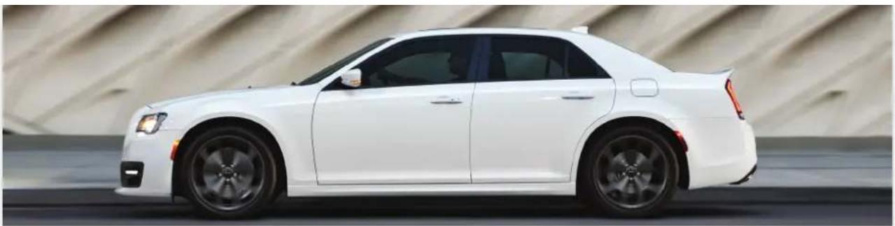
natural_image
Side profile of a white sedan on a curved road, no visible text or symbols
Whether it's providing information about specific product features, taking a tour through your vehicle's heritage, knowing what steps to take following an accident or scheduling your next appointment, we know you'll find the app an important extension of your Chrysler brand vehicle.
Simply download the app, select your make and model and enjoy the ride. To get this app, go directly to the App Store ^® or Google Play ^® Store and enter the search keyword "Chrysler" (U.S. residents only).
U.S. Canada
mopar.com/om
DOWNLOAD A FREE ELECTRONIC COPY OF THE MOST UP-TO-DATE OWNER'S MANUAL, UCONNECT AND WARRANTY BOOKLETS
owners.mopar.ca