
Voyager (2024) - Automobile Chrysler - Free user manual and instructions
Find the device manual for free Voyager (2024) Chrysler in PDF.


| Product Type | Automotive – Minivan |
| Brand | Chrysler |
| Model | Voyager (2024) |
| Engine | 3.6L V6 |
| Transmission | 9-Speed Automatic |
| Fuel Type | Unleaded gasoline (87 octane recommended) |
| Fuel Capacity | Approximately 19.5 gallons (estimate based on similar models) |
| Seating Capacity | 7–8 passengers (Stow 'n Go seating available) |
| Keyless Entry | Keyless Enter 'n Go™ with Passive Entry |
| Remote Start | Standard (key fob range up to 328 ft / 100 m) |
| Power Sliding Doors | Yes, with hands-free operation (both sides) |
| Power Liftgate | Yes |
| Seat Configuration | Stow 'n Go fold-into-floor seats (2nd and 3rd row) |
| Infotainment System | Uconnect with voice recognition, Apple CarPlay, Android Auto |
| Safety – Airbags | Front, side, knee, and curtain airbags |
| Safety – Driver Assistance | Blind Spot Monitoring, Forward Collision Warning with Mitigation, ParkSense Rear Park Assist, Rear Cross Path detection |
| Safety – Braking | Anti-lock Brake System (ABS), Electronic Brake Control (EBC), Hill Start Assist |
| Safety – Tire Monitoring | Tire Pressure Monitoring System (TPMS) |
| Climate Control | Manual or Automatic (ATC) with rear controls |
| Headlights | Automatic headlights with LED daytime running lights |
| Mirrors | Power, heated, auto-dimming, with turn signal indicators |
| Wipers | Rain-sensing windshield wipers |
| Warranty | See Owner's Manual for details; Roadside Assistance included |
Frequently Asked Questions - Voyager (2024) Chrysler
User questions about Voyager (2024) Chrysler
0 question about this device. Answer the ones you know or ask your own.
Ask a new question about this device
Download the instructions for your Automobile in PDF format for free! Find your manual Voyager (2024) - Chrysler and take your electronic device back in hand. On this page are published all the documents necessary for the use of your device. Voyager (2024) by Chrysler.
USER MANUAL Voyager (2024) Chrysler
24 HOURS, 7 DAYS A WEEK AT YOUR SERVICE.
CALL 1-800-521-2779 OR VISIT CHRYSLER.RSAHELP.COM (USA) CALL 1-800-363-4869 OR VISIT FCA.ROADSIDEAID.COM (CANADA)
SERVICES: Flat Tire Service, Out Of Gas/Fuel Delivery, Battery Jump Assistance, Lockout Service and Towing Service.
FCA US LLC reserves the right to modify the terms or discontinue the Roadside Assistance Program at any time. The Roadside Assistance Program is subject to restrictions and conditions of use, that are determined solely by FCA US LLC.
Please see the Customer Assistance chapter in this Owner's Manual for further information.
Vehicle images are for illustration purposes only. Actual products sold may vary.
This Owner's Manual illustrates and describes the operation of features and equipment that are either standard or optional on this vehicle. This manual may also include a description of features and equipment that are no longer available or were not ordered on this vehicle. Please disregard any features and equipment described in this manual that are not on this vehicle. FCA US LLC reserves the right to make changes in design and specifications, and/or make additions to or improvements to its products without imposing any obligation upon itself to install them on products previously manufactured.
With respect to any vehicles sold in Canada, the name FCA US LLC shall be deemed to be deleted and the name FCA Canada Inc. used in substitution therefore.
This Owner's Manual is intended to familiarize you with the important features of your vehicle. Your most up-to-date Owner's Manual, Radio Instruction Manual and Warranty Booklet can be found by visiting the website on the back cover.
WARNING: Operating, servicing and maintaining a passenger vehicle or off-highway motor vehicle can expose you to chemicals including engine exhaust, carbon monoxide, phthalates, and lead, which are known to the State of California to cause cancer and birth defects or other reproductive harm. To minimize exposure, avoid breathing exhaust, do not idle the engine except as necessary, service your vehicle in a well-ventilated area and wear gloves or wash your hands frequently when servicing your vehicle. For more information go to www.P65Warnings.ca.gov/passenger-vehicle.

TABLEOFCONTENTS
1 INTRODUCTION 6
2 GETTING TO KNOW YOUR VEHICLE 11
3 GETTING TO KNOW YOUR INSTRUMENT PANEL 57
4 STARTING AND OPERATING 72
5 MULTIMEDIA 100
6 SAFETY.... 117
7 IN CASE OF EMERGENCY.... 163
8 SERVICING AND MAINTENANCE 184
9 TECHNICAL SPECIFICATIONS 223
10 CUSTOMER ASSISTANCE.... 228
11 INDEX 233
INTRODUCTION
SYMBOLSKEY. 7
VEHICLEMODIFICATIONS/ALTERATIONS. . . . . . 7
SYMBOLGLOSSARY. 7
Remote Start Front Defrost Activation —
If Equipped 1
Remote Start Comfort Systems — If Equipped
Remote Start Windshield Wiper De-Icer
Activation — If Equipped ....
Remote Start Abort Message ....
VEHICLESECURITYSYSTEM—IFEQUIPPED.....16
To Arm The System ....
To Disarm The System ....
Rearming Of The System ....
Security System Manual Override ..... 17
DOORS 17
Manual Door Locks ....
Power Door Locks — If Equipped .....
Keyless Enter 'n Go™ — Passive Entry ...
Automatic Unlock Doors On Exit — If Equipp
Manual Sliding Side Door .....
Power Sliding Side Door — If Equipped ..... 21
Child Protection Door Lock System - Rear Doors Lan22 Change Assist - If Equipped ..... 3 9
STEERINGWHEEL 23
Tilt/Telescoping Steering Column .....
Heated Steering Wheel — If Equipped .....
SEATS 23
Manual Adjustment (Front Seats) — If Equipped
Manual Adjustment (Rear Seats) .....
Power Adjustment (Front Seats) — If Equipped
Heated Seats ....
Head Restraints 33
UconnectVoiceRecognition—IfEquipped..... 3 5
Introducing Voice Recognition ....
Basic Voice Commands 35
- 5 Get Started .... 3
Additional Information
MIRRORS. 36
Inside Rearview Mirror 36
flluminated Vanity Mirrors - If Equipped .
Outside Mirrors 3
16 Conversation Mirror
1 6 Power Mirrors - If Equipped 37
Outside Mirrors Folding Feature 37
Heated Mirrors — If Equipped ..... 37
.Wandshield Wiper Operation 41
2 Rain Sensing Wipers - If Equipped 4
. Rear Wiper And Washer 42
CLIMATECONTROLS 42
Manual Climate Control Descriptions And
Functions 42
3 6limate Voice Commands 4 6
Operating Tips 47
INTERIORSTORAGEANDEQUIPMENT. . . . . . . 47
Storage 47
USB/AUX Control 50
Power Outlets 51
WINDOWS 52
Power Windows 52
Automatic Window Features 53
Reset Auto Up 53
Wind Buffeting 53
HOOD. 54
Opening 54
To Close The Hood 54
HIFTGATE. 54
- To38nlock/Open The Liftgate 54
To Lock/Close The Liftgate 5 5
Power Liftgate - If Equipped 55
Cargo Area Features 56
GETTINGTOKNOWYOUR INSTRUMENTPANEL
BASEINSTRUMENTCLUSTER. 57
Base Instrument Cluster Descriptions .....
PREMIUMINSTRUMENTCLUSTER. 59
Premium Instrument Cluster Descriptions . .
INSTRUMENTCLUSTERDISPLAY. 60
Instrument Cluster Display Location And
Controls 60
OillifeReset
Instrument Cluster Display Menu Items
Battery Saver On/Battery Saver Mode
Message — Electrical Load Reduction Actions
If Equipped ....
WARNINGLIGHTSANDMESSAGES. 65
Red Warning Lights
Yellow Warning Lights
Yellow Indicator Lights
Green Indicator Lights
White Indicator Lights
Blue Indicator Lights
ONBOARD DIAGNOSTIC SYSTEM—OBDII ..... 7 0
Onboard Diagnostic System (OBD II)
Cybersecurity 71
EMISSIONSINSPECTIONANDMAINTENANCE
PROGRAMS. 71
STARTING ANDOPERATING
STARTINGTHEENGINE 72
Normal Starting 72
Auto Park
Extended Park Starting 74
If Engine Fails To Start .... Enabling And Disabling ParkSense .... 87
Cold Weather Operation
(Below -22°F Or -30°C)
After Starting — Warming Up The Engine
To Turn Off The Engine Using
ENGINE START/STOP Button
ENGINEBLOCKHEATER-IFEQUIPPED. 75
ENGINEBREAK-INRECOMMENDATIONS. ..... 7 5
PARKINGBRAKE. 76
Electric Park Brake (EPB) 76
AUTOMATICTRANSMISSION. 78
IgnitionParkInterlock
Brake/Transmission Shift Interlock (BTSI)
64 System 79
9-Speed Automatic Transmission
3.5 Gear Ranges
7ACTIVENOISECANCELLATION. 81
POWERSTEERING. 81
9Stop/StartSystem—IfEquipped. 81
70AutostopMode
7 0Possible Reasons The Engine Does Not
Autostop
To Start The Engine While In Auto Stop/Start
To Manually Turn Off The Stop/Start System
To Manually Turn On The Stop/Start System
System Malfunction
CRUISECONTROLSYSTEMS—IFEQUIPPED .... 8 3
Cruise Control
PARKSENSERARPARKASSIST-IFEQUIPPED.84
ParkSense Sensors
ParkSense Warning Display
ParkSense Display
Enabling And Disabling ParkSense 87
Service The ParkSense Rear Park Assist
7 System 87
. Clearing The ParkSense System ..... 8 8
ParkSense System Usage Precautions ..... 8 8
PARKVIEWREARBACKUPCAMERA. 89
REFUELINGTHEVEHICLE 89
VEHICLELOADING 90
Certification Label 90
TRAILERTOWING. 91
Common Towing Definitions .....
.Trailer. .Hilton 8 Classification 9 2
Trailer Towing Weights
(Maximum Trailer Weight Ratings) 93
Vehicle Loading Chart 93
Trailer And Tongue Weight 95
Towing Requirements 95
Towing Tips 97
RECREATIONALTOWING(BEHINDMOTORHOME) .97
Towing 1This Vehicle Behind Another Vehicle . . . 9;
DRIVINGTIPS 98
Driving On Slippery Surfaces 98
Driving Through Water 99
. . 82
MU83TIMEDIA
8 3UCONNECTSYSTEMS....10 0
CYBERSECURITY 100
8 3CONNECTSETTINGS....100
Customer Programmable Features ..... 1 0 1
8 5 STEERINGWHEELAUDIOCONTROLS. . . . . . . . 1 1 6
8 5 Radio Operation 1 1 6
8 5 Media Mode ..... 1 1 6
RADIOOPERATIONANDMOBILEPHONES. . . . 1 1 6
Regulatory And Safety Information .....
SAFETY
SAFETYFEATURES. 117
Anti-Lock Brake System (ABS)
Rear Seat Reminder Alert (RSRA) ..
Electronic Brake Control (EBC) System
AUXILIARYDRIVINGSYSTEMS. 121
Blind Spot Monitoring (BSM) — If Equipped
Forward Collision Warning (FCW) With
Mitigation — If Equipped .....
Tire Pressure Monitoring System (TPMS)
OCCUPANTRESTRAINTSYSTEMS. 129
Occupant Restraint Systems Features
Important Safety Precautions
Seat Belt Systems
Supplemental Restraint Systems (SRS)
Child Restraints
SAFETYTIPS. 160
Transporting Passengers
Transporting Pets
Connected Vehicles
Safety Checks You Should Make Inside
The Vehicle 160
Periodic Safety Checks You Should Make
Outside The Vehicle
Exhaust Gas
Carbon Monoxide Warnings 1
IN CASEOF EMERGENCY
^1 ^1 ^6 HAZARDWARNINGFLASHERS ..... 1 6 3
SOSANDASSISTMIRROR—IFEQUIPPED. . . . . 1 6 3
JACKINGANDTIRECHANGING—IFEQUIPPED ..165
Preparations For Jacking 166
Jack And Spare Tire Location
^1 Equipment Removal
1 18 Jacking Instructions 167
Road Tire Installation 170
121 Portable Air Compressor — If Equipped
Return Inflatable Spare Tire
1 2 5 TIRESERVICEKIT—IFEQUIPPED. 1 7 2
127 JUMPSTARTING. 177
Preparations For Jump Start ....
Jump Starting Procedure
REFUELINGINEMERGENCY-IFEQUIPPED....178
IFYQURENGINEOVERHEATS 179
MANUALPARKRELEASE. 180
Pressure Washing 188
VEHICLEMAINTENANCE 188
Engine Oil 188
Engine Oil Filter 188
Engine Air Cleaner Filter 188
Accessory Drive Belt Inspection 189
Air Conditioner Maintenance 189
Body Lubrication 191
Windsfield ^6 Wiper Blades 191
Exhaust System 194
Cooling System 194
Brake System 197
Automatic Transmission 197
Fuses 198
Bulb Replacement 204
7TIRES. 207
78 Tire Safety Information 207
Tires - General Information 213
Tire Types 216
Spare Tires - If Equipped 216
Wheel And Wheel Trim Care 217
Snow Traction Devices 218
Tire Rotation Recommendations 219
DEPARTMENTOFTRANSPORTATIONUNIFORM
TIREQUALITYGRADES. 219
Treadwear 219
Traction Grades 2 20
Temperature Grades 2 2 0
STORINGTHEVEHICLE. 220
BODYWORK 221
Protection From Atmospheric Agents ..... 2 2 1
Body And Underbody Maintenance 221
Preserving The Bodywork 221
INTERIORS. 2 2 2
Seats And Fabric Parts ....
Plastic And Coated Parts
Leather Surfaces 2 2 2
Glass Surfaces 2
TECHNICALSPECIFICATIONS
VEHICLEIDENTIFICATIONNUMBER(VIN).....2 2 3
BRAKESYSTEM. 2 2 3
WHEELANDTIRETORQUESPECIFICATIONS...223
Torque Specifications
FUELREQUIREMENTS. 2 2 4
3.6L Engine 2
Reformulated Gasoline 2
Gasoline/Oxygenate Blends 2
Do Not Use E-85 In Non-Flex Fuel Vehicles
CNG And LP Fuel System Modifications ...
Methylcyclopentadienyl Manganese Tricarbonyl
(MMT) In Gasoline
Materials Added To Fuel 2
Fuel System Cautions ....
FLUIDCAPACITIES. 2 2 6
ENGINEFLUIDSANDLUBRICANTS ..... 2 2 6
CHASSISFLUIDSANDLUBRICANTS ..... 2 2 7
CUSTOMERASSISTANCE
222 SUGGESTIONSFOROBTAININGSERVICEFOR
YOURVEHICLE. 228
Prepare For The Appointment 2 2 8
Prepare A List 2 28
Be Reasonable With Requests 2 2 8
IFYOUNEEDASSISTANCE 228
Roadside Assistance 228
FCA US LLC Customer Center 229
FCA Canada Customer Care 2 2 9
2 2 3 Mexico 22 9
Puerto Rico And US Virgin Islands ..... 229
4 Customer Assistance For The Hearing Or
4 Speech Impaired (TDD/TTY) 2 2 9
2 4 Service Contract 2 3 0
WARRANTYINFORMATION....230
M204PAR®PARTS 230
REPORTINGSAFETYDEFECTS. 230
2 In The 50 United States And Washington, D.C. . . 230
2 5In Canada 2 3 1
25 PUBLICATIONORDERFORMS. 231
ChangeOfOwnershipOrAddress. 231
GENERALINFORMATION. 231
INTRODUCTION
Dear Customer,
Congratulations on the purchase of your new Chrysler vehicle. Be assured that it represents precision workmanship, distinctive styling, and high quality.
This Owner's Manual has been prepared with the assistance of service and engineering specialists to acquaint you with the operation and maintenance of your vehicle. It is supplemented by customer-oriented documents. Within this information, you will find a description of the services that FCA US LLC offers to its customers as well as the details of the terms and conditions for maintaining its validity. Please take the time to read all of these publications carefully before driving your vehicle for the first time. Following the instructions, recommendations, tips, and important warnings in this manual will help ensure safe and enjoyable operation of your vehicle.
This Owner's Manual describes all versions of this vehicle. Options and equipment dedicated to specific markets or versions are not expressly indicated in the text. Therefore, you should only consider the information that is related to the trim level, engine, and version that you have purchased. Any content introduced throughout the Owner's Information, which may or may not be applicable to your vehicle, will be identified with the wording "If Equipped". All data contained in this publication are intended to help you use your vehicle in the best possible way. FCA US LLC aims at a constant improvement of the vehicles produced. For this reason, it reserves the right to make changes to the model described for technical and/or commercial reasons. For further information, contact an authorized dealer.
When it comes to service, remember that authorized dealers know your Chrysler vehicle best, have factory-trained technicians and genuine Mopar® parts, and care about your satisfaction.
SYMBOLSKEY
| WARNING!These statements apply to | operating procedures that could result in a co bodily injury and/or death. |
| CAUTION!These statements apply to | procedures that could result in damage to y vehicle. |
| NOTE:A suggestion which will improve installation, operation, and reliability. If n lowed, may result in damage. | |
| TIP:General ideas/solutions/suggestions | on easier use of the product or fun |
| PAGEREFERENCEARROW page | Follow this reference for additional mation on a particular feature. |
| FOOTNOTE | Supplementary and relevant informa pertaining to the topic. |
If you do not read the entire Owner's Manual, you may miss important Observe all Cautions and Warnings.
VEHICLEMODIFICATIONS/ALTERATIONS
| WARNING! |
| Any modifications or alterations to this vehicle could seriously affectiness and safety and may lead to a collision resulting in serious in |
1
SYMBOLGLOSSARY
Some car components have colored labels with symbols indicating precautions to observed when using this component. It is important to follow all warnings wheating your vehicle. See below for the definition of Lpage symbol
NOTE:
Warning and Indicator lights are different based upon equipment options and cu vehicle status. Some telltales are optional and may not appear.
| RedWarningLights | |
 | Air Bag Warning Light page 65 |
i  . . | Battery Charge Warning Light page 65Brake Warning Light page 65 |
 | Door Open Warning Light page 65 |
 | Electric Power Steering (EPS) Fault Warning Light page 66 |
 | Electronic Throttle Control (ETC) Warning Light page 66 |
 | Engine Coolant Temperature Warning Light page 66 |
 | Hood Open Warning Light page 66 |
| RedWarningLights | |
 | Liftgate Open Warning Light page 66 |
 | Oil Temperature Warning Light page 66 |
 | Oil Pressure Warning Light page 66 |
 | Seat Belt Reminder Warning Light page 67 |
 | Transmission Temperature Warning Light page 67 |
 | Vehicle Security Warning Light page 67 |
| YellowWarningLights | |
 | Anti-Lock Brake System (ABS) Warning Light page 67 |
 | Electric Park Brake Warning Light page 67 |
 | Electronic Stability Control (ESC) Active Warning Light page 67 |
 | Electronic Stability Control (ESC) OFF Warning Light page 67 |
 | Engine Check/Malfunction Indicator Warning Light (M page 68 |
 | Fuel Level Sensor Failure Warning Light page 68 |
| YellowWarningLights | |
 | Low Fuel Warning Light page 68 |
 | Low Washer Fluid Warning Light page 68 |
 | Service Automatic Emergency Braking (AEB) or Pedestriagency Braking (PEB) Warning Light page 68 |
 | Service Stop/Start System Warning Light page 68 |
 | Tire Pressure Monitoring System (TPMS) Warning Lig page 68 |
| YellowIndicatorLights | |
 | Automatic Emergency Braking (AEB) or Pedestrian Emerging (PEB) OFF Indicator Light page 69 |
| WhiteIndicatorLights | |
B  | Cruise Control Ready Indicator Light page 70 |
| Set Speed Display Indicator Light page 70 | |
| GreenIndicatorLights | |
 | Cruise Control Set Indicator Light page 69 |
 | Front Fog Indicator Light page 69 |
 | Parking/Headlights On Indicator Light page 69 |
 | Stop/Start Active Indicator Light page 70 |
 | Turn Signal Indicator Lights page 70 |
| BlueIndicatorLights | |
| High Beam Indicator Lightpage 70 | |
| BlueIndicatorLights | |
| High Beam Indicator Lightpage 70 | |
| BlueIndicatorLights | |
| High Beam Indicator Lightpage 70 | |
| BlueIndicatorLights | |
| High Beam Indicator Light page 70 | |
| BlueIndicatorLights | |
| High Beam Indicator Lightpage 70 | |
- The key fob LED light brightness is designed ToLock/UnlockTheDoorsAndLiftgate
KEY FOB
Your vehicle is equipped with a key fob which supports Passive Entry, Remote Keyless Entry (RKE), Keyless Enter 'n Go™ (if equipped), and Remote Start (if equipped). The key fob allows you to lock or unlock all doors and liftgate, as well as activate the Panic Alarm from distances up to approximately 66 ft (20 m). The key fob does not need to be pointed at the vehicle to activate the system. The key fob also contains an emergency key, which is stored in the rear of the key fob.
The emergency key allows for entry into the vehicle should the battery in the vehicle or the key fob become depleted. The emergency key is also for locking/unlocking the glove compartment. You can keep the emergency key with you when valet parking.
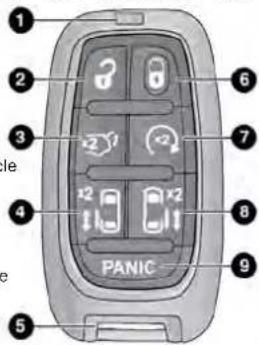
KeyFob
NOTE:
- The key fob's wireless signal may be blocked1 if—theED Light key fob is located next to a mobile phone, 2 laptop, Unlock
other electronic device. This may result in po8r - Liftgate
performance. - A low key fob battery condition may be indicated by Emergency Key a message in the instrument cluster display, or by Remote Start the LED light on the key fob. If the LED key_fob Right Power Sliding Side Door no longer illuminates from key fob button pushes. Panic Alarm then the key fob battery requires replacement.
Push and release the unlock button on the to unlock the driver's front door and sliding

twice within five seconds to unlock all doors and the liftgate. Push and release the lock button on the key to lock all doors and the liftgate.
When the doors are unlocked, the turn signals will flare and the illuminated entry system will be activated. When the doors are locked, the turn signals will flare and the horn will chirp. Settings in the Uconnect system can change to lights only, chirp only, or both.
VehiclesEquippedWithKeylessEnter'nGo™—PassiveEntry
If one or more doors are open, or the liftgate is of the doors can be locked. The doors will unlock again only if the key fob is inside the passenger compartment.
All doors can be programmed to unlock on the first push of the unlock button within the Uconnect system page 100.
KeyLeftVehicleFeature
If a valid key fob is no longer detected inside the while the vehicle's ignition system is in the ON/RUN START position, the message "Key Fob Has Left The Vehicle" will be shown in the instrument cluster display along with an interior chime. An exterior audible and visual alert will also be activated to warn the driver.
The vehicle's horn will rapidly chirp three times along with a single flash of the vehicle's exterior lights.
NOTE:
- The doors have to be open and then closed in order for the vehicle to detect a key fob. The Key Left Vehicle feature will activate when the first door is closed and no key fob is detected in the vehicle. If the warning has been activated, and the other doors are closed, no other warnings will be issued.
- These alerts will not be activated in situations where the vehicle's engine is left running with the key fob inside, or the key fob's wireless signals are blocked.
ReplacingTheBatteryInTheKeyFob
The recommended replacement battery is one CR2032 battery.
NOTE:
- Customers are recommended to use a battery obtained from Mopar®. Aftermarket coin battery dimensions may not meet the original OEM coin battery dimensions.
- Batteries contain harmful chemicals. Dispose old batteries by placing them in correct containers according to the law or by taking them to a ship, where they will be handled appropriately.
- Perchlorate Material — special handling may apply See www.dtsc.ca.gov/hazardouswaste/perchlorate for further information. 5.
-
Do not touch the battery terminals that are back housing or the printed circuit board.
-
Remove the emergency key by pushing the mechanical release button on the side of the key fob with your thumb and then pulling the key out with your other hand.
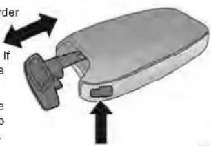
EmergencyKeyRemoval
- Insert a coin or a flat-blade screwdriver into exposed slot and carefully pry on both sides, engage the snaps. Gently remove the back of from the fob, being careful not to damage a snaps.
Remove the battery by sliding the battery re in its pocket until the battery lifts up. Remo depleted battery from the battery pocket and pose appropriately.
- deflera new CR2032 battery ensuring that the (+) side is facing upwards. Push the battery pocket until it is firmly seated in place and apply under both tabs.
- Align the back cover into its original position snap it back in place by pushing it against on the until it is seated all around.
WARNING!
- The integrated key fob contains a coin cell battery. Do not ingest the battery; there is a chemical bur hazard. If the coin cell battery is swallowed, it can cause severe internal burns in just two hours and can lead to death. - If you think a battery may have been swallowed or placed inside any part of the body, seek immediate medical attention. - Keep new and used batteries away from children. If the battery compartment does not close securely, stop using the product and keep it away from children.
over ProgrammingAndRequesting any of the AdditionalKeyFobs
Programming the key fob may be performed by an authorized dealer.
DIS NOTE:
- Once a key fob is programmed to a vehicle, it can be repurposed and reprogrammed to another vehicle.
- Only key fobs that are programmed to the vehicle electronics can be used to start and operate the vehicle.
WARNING!
• Always remove the key fobs from the vehicle lock all doors when leaving the vehicle up
- For vehicles equipped with Keyless Enter Ignition, always remember to place the ig the OFF position when exiting the vehicle
After placing the ignition in the ON/RUN position, IIGNITIONSWITCH Vehicle Security Light will turn on for three seconds for
a and bulb check. If the light remains on after the bulb
check. it indicates that there is a problem with
tronics. In addition, if the light begins to flash
GoTM check it indicates that someone attempted
the, ending with an invalid key, fab. In the
start the engine with an invalid key job. In that, a valid key fish is used to start the one
that a valid key job is used to start the eng
is an issue with the vehicle electronics, the en
start and shut off after two seconds.
ming the a Vehicle Security Light turns on during no
nk key job vehicle security light turns on during the vehicle operation (vehicle running for longer than
vehicle operation (vehicle turning for longer than 10 seconds), it indicates that there is a fault
10 seconds), it indicates that there is a fault
tronics. Should this occur, have the vehicle serv
soon as possible by an authorized dealer.
KEYLESS ENTER 'N GO™ IGNITION
after the
This feature allows the driver to operate the
switch with the push of a button as long
is in the passenger compartment.
The START/STOP ignition button has four operating
gine with/stop ignition button has four operating positions: three of which are labeled and will illuminate
positions, three of which are labeled and will illuminate
when in position. The three positions are OFF, ACC, a
ON/RUN. The fourth position is START. During START,
RUN will illuminate.
Duplication of key fobs may be performed at rized dealer. This procedure consists of progra blank key fob to the vehicle electronics. A I is one that has never been programmed.
NOTE:
- When having the Sentry Key Immobilizer sy
serviced, bring all vehicle keys with you to rized dealer. - Emergency keys must be ordered to the cut to match the vehicle locks.
- It is not mandatory to replace the key for emergency key is needed, and vice versa.
| an autho-CAUTION! |
| reThe keyentry Key Immobilizer system is not of with some aftermarket Remote Start systems, these newtems may result in vehicle starting and loss of security protection. |
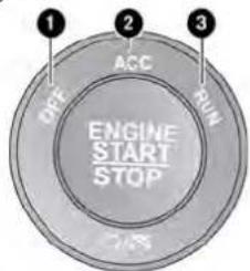
A0205000912US
KeylessPushButtonIgnition
All of the key fobs provided with your new vehicle have been programmed to the vehicle electronics
SENTRYKEY
The Sentry Key Immobilizer system prevents unauthor page 231.
ized vehicle operation by disabling the engine. The sys-
tem does not need to be armed or activated. Operation.
is automatic, regardless of whether the vehicle is A key fob th
locked or unlocked.
The system uses a key fob, keyless push button ignition
and a Radio Frequency (RF) receiver to prevent unau-
thorized vehicle operation. Therefore, only key fobs that
are programmed to the vehicle can be used to start and
operate the vehicle. The system cannot reprogram a
key fob obtained from another vehicle.
The SYS-
Operation 1 - OFF
A key job that has not been programmed is also a censid-
ered an invalid key. 3 - ON/RUN
(No text)
The push button ignition can be placed in the modes:
OFF
• The engine is stopped
- Some electrical devices (e.g. power locks, alarm, etc.) are still available
ACC
• The engine is stopped
- Some electrical devices are available (e.g. power windows)
ON/RUN
- Driving position
- All electrical devices are available (e.g. climate trols, etc.)
START
- The engine will start (when foot is on the pedal)
The engine only runs in the ON/RUN ignition pos from a Remote Start request.
In case the ignition switch does not change with push of a button, the key fob may have a low depleted battery. In this situation, a backup method be used to operate the ignition switch. Put the side (side opposite of the emergency key) of the against the START/STOP ignition button and push operate the ignition switch.
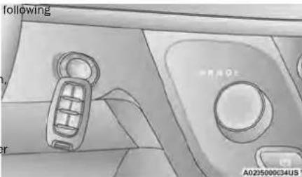
BackupStartingMethod
con
WARNING!
- When leaving the vehicle, always remove the rake job from the vehicle and lock your vehicle.
- Never leave children alone in a vehicle, or position or access to an unlocked vehicle.
- Allowing children to be in a vehicle unattended dangerous for a number of reasons. A child of the people could be seriously or fatally injured. Child should be warned not to touch the parking nose, brake pedal or the gear selector.
● Key fob Do not leave the key fob in or near the in a location accessible to children, and do leave the Keyless Enter 'n Go™ Ignition in ON/RUN position. A child could operate power dows, other controls, or move the vehicle
- Do not leave children or animals inside par vehicles in hot weather. Interior heat buildup cause serious injury or death.
CAUTION!
An unlocked car is an invitation for theives remove the key fobs from the vehicle and doors when leaving the vehicle unattended.
Always lock all
NOTE:
- The key fob may not be detected by the vehicle less Enter 'n Go™ system if it is located next to mobile phone, laptop or other electronic device; these devices may block the key fob's wireless signal and prevent the Keyless Enter 'n Go™ system from starting the vehicle.
- For the proper engine starting procedure, see key page 72.
REMOTESTART—IFEQUIPPED

This system uses the key fob to start the engine conveniently from outside the vehicle while still maintaining security. The system has a range of 328 ft (100 m).
brake Remote Start is used to defrost windows in cold weather and to reach a comfortable climate in all ar vehicle or ent conditions before the customer enters the vehicle. not
NOTE:
Obstructions between the vehicle and key fob may reduce this range page 231.
WARNING!
- Do not start or run an engine in a closed confined area. Exhaust gas contains carbon oxide which is odorless and colorless. Carbon oxide is poisonous and can cause serious in death when inhaled.
-
Keep key fobs away from children. Operation Remote Start system, windows, door locks or controls could cause serious injury or death.
-
The ignition must be placed in the ON/R before the Remote Start sequence can be for a third cycle.
All of the following conditions must be met engine will Remote Start:
uryGear selector in PARK
- Doors closed
of Hôdê closed
other Liftgate closed
- Hazard switch off
- Brake switch inactive (brake pedal not pre
- Battery at an acceptable charge level
the Panfe key button not pushed
- System not disabled from previous Remote - will chirp event
de Vehiclea Security system indicator flashing
- Ignition in OFF position
shufuelthdevel meets minimum requirement
- Vehicle Security system is not signaling at
nd Malfunction Indicator Light (MIL) is not illu
T0 Position EXIT REMOTE START MODE
To drive the vehicle after starting the Remote Start system, either push and release the unlock button on the key job to unlock the doors, or unlock the vehicle u
Keyless Enter 'n Go™ — Passive Entry via the handles, and disarm the Vehicle Security system (if equipped). Then, prior to the end of the 1 cycle, push and release the START/STOP ignition button.
The Remote Start system will turn the engine off if Remote Start button on the key fob is pushed again, If the engine is allowed to run for the entire 15 m cycle. Once the ignition is placed in the ON/RUN position, the climate controls will resume previously set operations (temperature, blower control, etc.).
NOTE:
- For vehicles equipped with the Keyless Enter 'n Go'
- Passive Entry feature, the message "Remote Start
Active - Push Start Button" will show in the instr.
rusiment cluster display until you push the START/STOP
ted ignition button.
- To avoid unintentional shutdowns, the system will disable for two seconds after receiving a valid Remote Start request.
HOW TO USE REMOTE START
Push and release the Remote Start button on fob twice within five seconds. The vehicle doors lock, the parking lights will flash, and the horn twice (if programmed). Then, the engine will state the vehicle will remain in the Remote Start m 15 minute cycle.
Pushing the Remote Start button a third time engine off.
To drive the vehicle, push the unlock button the ignition in the ON/RUN position.
NOTE:
- With Remote Start, the engine will only run 15 minutes.
- Remote Start can only be used twice.
- If an engine fault is present or fuel level is vehicle will start and then shut down in 10
- The parking lights will turn on and remain Remote Start mode.
- For security, power window operations are disabled when the vehicle is in the Remote Start mode.
WARNING!
Do not start or run an engine in a clo confined area. Exhaust gas contains carbon oxide (CO) which is odorless and colorless monoxide is poisonous and can cause ser low the injury of death when inhaled.
- Keep key fobs away from children. Operation of the Renioge Start system, windows, door locks or other controls could cause serious injury or death.
sed garage or mon- Carbon
JS
[Non-Text]
a of the
of the
r other
[Non-Text]
REMOTE START FRONT DEFROST ACTIVATION — IF EQUIPPED
Manual Temperature Control(MTC)—If Equipped
- In ambient temperatures of 40^ (4.5°C) or the climate settings will default to maximum
REMOTE START ABORT MESSAGE
below. One of the following messages will display in the inst heat ment cluster display if the vehicle fails to remote start defrost or exits Remote Start prematurely:
When Remote Start is active, and the outside ambient air with fresh air entering the cabin. If the front temperature is 40^ F ( 4.5^ C) or below, the system will enter expires, the vehicle will enter Mix Mod automatically activate front defrost for 15 minutes. In ambient temperatures from 40^ F ( 4.5^ C) to less. The time is dependent on the ambient temperature ( 26^ F ( 26^ C), the climate settings will be suitable. Once the timer expires, the system will automate the last settings selected by the driver. Cally adjust the settings depending on ambient conditions. See “Remote Start Comfort Systems — if Equipped” in the next section for detailed operation. In ambient temperatures of 78^ F ( 26^ C) or the climate settings will default to MAX A/C, mode, with Recirculation on.
- Remote Start Canceled — Door Open - Remote Start Canceled — Hood Open
- Remote Start Canceled — Liftgate Open - Remote Start Canceled — Fuel Low
- Bit Level - Remote Start Canceled - Time Expired - Remote Start Canceled - System Fault
• Remote Start Disabled — Start Vehicle To Reset
The instrument cluster display message stays active until the ignition is placed in the ON/RUN position.
REMOTE START COMFORT SYSTEMS — IF EQUIPPED
NOTE:
When Remote Start is activated, the front and defroster will automatically turn on in cold weaditions. The heated steering wheel and driver seat feature will also turn on if programmed fort menu screen within Uconnect Settings page 100. In warm weather, the driver ve feature will automatically turn on when Remote activated, if programmed via the Comfort menu. The vehicle will adjust the climate control sett depending on the outside ambient temperature.
These features will stay on through the duration of Remote Start, or until the ignition is placed in ON/RUN position. The climate control settings will change, and exit the automatic defaults, if man adjusted by the driver while the vehicle is in Start is mode. This includes turning the climate co off using OFF button.
VEHICLESECURITYSYSTEM— IFEQUIPPED
AutomaticTemperatureControl(ATC)—IfEquipped
The climate controls automatically adjust to an temperature and mode settings depending on the side ambient temperature. This will occur until it is placed in the ON/RUN position where controls will resume their previous settings.
^1 REMOTE START WINDSHIELD WIPER DE-ICER ACTIVATION — d ^2 mal EQUIPPED
The When Remote Start is active and the outside temperature is less than 33°F (0.6°C), the Wind Wiper De-Icer will activate. Exiting Remote Start resume its previous operation. If the Windshield De-Icer was active, the timer and operation will continue.
The Vehicle Security system monitors the vehicle doors for unauthorized entry and the ignition switch for unauthorized operation. When the alarm is activated, the interior switches for door locks, power sliding doors an power liftgate are disabled. The Vehicle Security system provides both audible and visible signals. If something triggers the alarm, the Vehicle Security system will provide the following audible and visible signals: the horn drive pulse, the parking lights and/or turn signals will flash, and the Vehicle Security Light in the instrument will flash.
TO ARM THE SYSTEM
NOTE:
SECURITY SYSTEM MANUAL
OVERRIDE
Follow these steps to arm the Vehicle Security
system: driver's door key cylinder and the liftgate
The Vehicle Security system will not arm if you lock doors using the manual door lock.
- Make sure the vehicle's ignition is placed position.
the OFF Security system.
DOORS
For vehicles equipped with Keyless Enter Go™ — Passive Entry, make sure the ve ignition system is OFF.
- The Vehicle Security system remains armed du n icle power liftgate entry. Pushing the liftgate button not disarm the Vehicle Security system. If sor enters the vehicle through the opened liftgate,
MANUAL DOOR LOCKS
- Perform one of the following methods to I vehicle:
k opens any door, the alarm will sound.
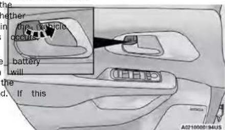
The lock each door, rotate the door lock knob on each door trim panel forward. To unlock the front doors, put the inside door handle to the first detent or rotate t
○ Push lock on the interior power door lo with the driver and/or passenger door op
- When the Vehicle Security system is armed, the switch nor power door lock switches will not unlock n. doors.
dooroulock button until the ribbing is visible. To unlock etherear doors, rotate the door lock button until the indicatorvi-is visible.
○ Push the lock button on the exterior Pa Entry door handle with a valid key fob in the same exterior zpage 19.
The Vehicle Security system is designed to prote available. However, you can create conditions where system will give you a false alarm. If one of
○ Push the lock button on the key fab.
- If any doors are open, close them.
TO DISARM THE SYSTEM
The Vehicle Security system can be disarmed of the following methods:
If the Vehicle Security system is armed and the becomes disconnected, the Vehicle Security system remain armed when the battery is reconnected; tiperior lights will flash, and the horn will sound occurs, disarm the Vehicle Security system.
- If this
- Push the unlock button on the key fob.
- Grab the Passive Entry door handle (if equi page 19.
- Cycle the vehicle ignition system out of the position.
REARMING OF THE SYSTEM
ManualFrontDoorLock
For vehicles equipped with Keyless Enter in something triggers the alarm and no action is taken Passive Entry, push the keyless ignition to alarm it, the Vehicle Security system will turn the STOP ignition button (requires at least one key fob in the vehicle).
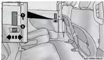
ManualRearDoorLockLocation
1 - Door Handle
2 - Manual Door Lock
If the door lock button is locked (no ribbing is when you shut the door, the door will lock. The make sure the key fob is not inside the vehicle closing the door.
NOTE:
The manual door locks will not lock or unlock liftgate.
WARNING!
- For personal security and safety in the collision, lock the vehicle doors before you well as when you park and leave the
- Never use the PARK position as a subs parking brake. Always apply the parking I when parked to guard against vehicle mo and possible injury or damage.
- When exiting the vehicle, always make a keyless ignition is in the OFF position, key fob from the vehicle and lock the
- Never leave children alone in a vehicle, access to an unlocked vehicle. Allowing one be in a vehicle unattended is dangerous, number of reasons. A child or others could or fatally injured. Children should be aware of visible when the parking brake, brake pedal or other foot.
Do not leave the key fob in or near in a location accessible to children, and leave the Keyless Enter 'n Go™ Ignition or ON/RUN position. A child could operate windows, other controls, or move the veh
POWER DOOR LOCKS — IF EQUIPPED
u drivepower door lock switch is on each front door trim vehicle panel. Use this switch to lock or unlock the doors.
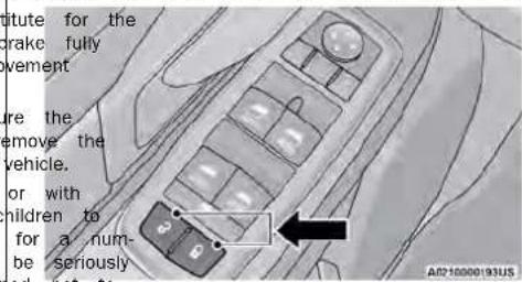
DriverPowerDoorLockSwitches
If you push the power door lock switch while the ig the vehicle, or do on, the ACC or ON/RUN position, and any front do on, the power locks will not operate. This prevents in the ACC you from accidentally locking your key fob in the vehi e power Placing the ignition in the OFF position or closing the door will allow the locks to operate. A chime will so if the ignition is in the ACC or ON/RUN position and door is open, as a reminder to place the ignition in OFF position and remove the key fob.
KEYLESS ENTER 'N GO™ — PASSIVE ENTRY
The Passive Entry system is an enhancement vehicle's Remote Keyless Entry system and a Keyless Enter 'n Go™ — Passive Entry. This f allows you to lock and unlock the vehicle's c out having to push the key fob lock or unlock
- The sliding side doors can be unlocked from outside using the Passive Entry system.
ToUnlockFromTheDriverOrPassengerSide:
with a valid key fob within 5 ft (1.5 m) of handle, grab the handle to unlock the vehicle.
the driver's door handle will unlock the driver's ot(s) with- doors (driver/sliding door) automatically. Grabbing k buttons
front passenger door handle to unlock all four and the liftgate automatically. The interior door lock knob will rotate when the door is unlocked
FrequencyOperatedButtonIntegratedKey
(FOBIK-Safe)
To minimize the possibility of unintentionally locking a key job inside your vehicle, the Passive Entry system equipped with an automatic door unlock feature.
There are three situations that trigger a FOBI search in any Passive Entry vehicle:
doors lock request is made by a valid key fob while panel door is open.
NOTE:
- Passive Entry may be programmed on/off through the Uconnect system page 100.
- The key fob may not be detected by the vehicle Passive Entry system if it is located next to a mobile phone, laptop, or other electronic device; these devices may block the key fob's wireless signal and prevent the Passive Entry handle from locking/unlocking the vehicle.
- If set by the customer in the Uconnect Settings, unlocking with Passive Entry will initiate illuminated approach (low beams, license plate lamp, position lamps) for the duration of 0, 30, 60 or 90 seconds. Passive Entry also initiates two flashes of the turn signals.
- If wearing gloves, if it has been raining/snowing, there is salt/dirt covering the Passive Entry door handle, the unlock sensitivity can be affected, resulting in a slower response time.
- The doors may unlock when water is sprayed Passive Entry door handles, if the key fob is outside of the vehicle within 5 ft (1.5 m) o handle.
- If the vehicle is unlocked by Passive Entry and no door is opened within 60 seconds, the vehicle will relock and will arm the security system (If equipped).
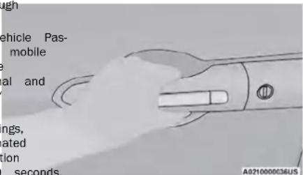
GrabTheDoorHandleToUnlock
- Either the driver door only or all doors will when you grab hold of the front driver's de depending on the selected setting in the Uc system → page 100. - All doors will unlock when the front passeng handle is grabbed regardless of the driver's unlock preference setting.
A lock request is made by the Passive Entry door handle while a door is open.
- A lock request is made by the door panel switch while the door is open. When any of these situations occur, after all open do are shut, the FOBIK-Safe search will be executed. If it detects a key fob inside the car, and it does not of any key fob outside the car, then the car will unlock alert the customer.
NOTE:
The vehicle will only unlock the doors when a valid sive Entry key fob is detected inside the vehicle, and valid key fob is detected outside the vehicle. The veh will not unlock the doors when any of the following ditions are met:
- The doors are manually locked using the door lock unless.
• Three attempts are made to lock the doors using the door panel switch and then the doors are closed. - There is a valid Passive Entry key fob outside the other door vehicle and within 5 ft (1.5 m) of either Passive Entry door handle.
NOTE:
On the third attempt ALL doors will lock and the key can be locked in the vehicle.
ToLockTheVehicle'sDoorsAndLiftgate
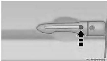
With one of the vehicle's key fobs within 5 ft the driver or passenger front door handle, push door handle lock button to lock all four doors liftgate.
natural_image
Close-up of a car door handle with a black arrow pointing to the left side (no text or symbols visible)PushTheDoorHandleButtonToLock
Do NOT grab the door handle when pushing handle button. This could unlock the door(s).
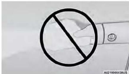
DoNOTGrabTheDoorHandleWhenLocking
NOTE:
(1.5 m) of After pushing the door handle lock button, the wait two seconds before you can lock or
doors, using either Passive Entry door hand is done to allow you to check if the ve by pulling the door handle, without the ve unlocking.
- If Passive Entry is disabled using the Uco tings, the key fob protection described in Operated Button Integrated Key (FOBIK-Safe)" remains active/functional.
- The Passive Entry system will not operate fob battery is depleted.
ToUnlock/EnterTheLiftgate
The liftgate Passive Entry unlock feature is b
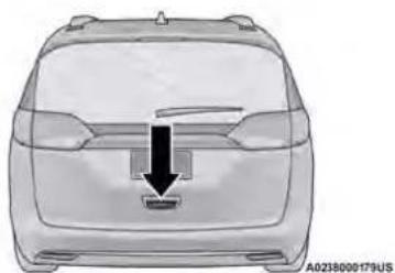
electronic liftgate release handle. With a valid Entry key fob within 5 ft (1.5 m) of the electronic liftgate release handle for a power vehicles equipped with Power Liftgate. Pull the tronic liftgate handle and lift for manual liftgate vehicles page 231.
natural_image
Top-down view of a car's rear bumper with a black arrow pointing to the front panel (no text or symbols)ElectronicLiftgateReleaseHandle
AUTOMATIC UNLOCK DOORS ON EXHUST — IF EQUIPPED
Unlock the This Unlock Doors Automatically On Exit feature unlocks all of the vehicle doors when any door is opened. The will occur only after the gear selector has been placed into the PARK position, after the vehicle has been driven (the gear selector has been placed out of PAR
eshd Seth doors closed).
The Unlock Doors Automatically On Exit feature will not operate if there is any manual operation of the door locks (lock or unlock).
The feature can be turned on or off in the Uconnec system → page 100.
.MANUAL SLIDING SIDE DOOR
The sliding door may be opened from the inside or outside. Push Pulteoutward on the exterior handle to open sliding door. The sliding door inside handle functions be rocking forward and back. Rocking the handle backwards opens the door and rocking forward releases the hold open latch in order to close the door.
NOTE:
If equipped with power sliding doors, using the manual door handle will activate the power opening/closing function. Allow the door to open or close fully on its own, without forcing it.
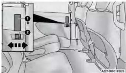
SideDoorHandleAndLockFunctions
1 - Door Handle 2 - Door Lock
To keep your door operating properly, observe lowing guidelines:
• Always open the door smoothly.
- Avoid high impacts against the door stop when ft (1.5 opening the door. This is very important when your vehicle is parked on an incline as the door will slide faster in the downhill direction.
- There is a hold-open latch that is activated when the sliding door is fully opened. This latch will keep your sliding door open on any incline. To close the sliding door after the hold-open latch is activated, you must rock the inside handle forward or pull outward on the exterior handle.
Always make sure that the sliding door is fully latched anytime the vehicle is in motion.
NOTE:
The left side sliding door cannot be opened while the fuel door is open.
The power sliding door may be power opened in several ways:
• Key fob
• Inside or outside handles
- Buttons located:
○ In the overhead console
○ Just inside the sliding door
○ On the outside handle
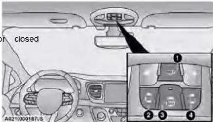
OverheadConsolePowerSwitches

Push the button on the key fob twice five seconds to open, close, or reverse power sliding door.
The key fob and the overhead console will operate the door when the door is locked. Have you require the sliding door to be unlocked. I vehicle is equipped with Passive Entry, pressing a button on the outside handle will unlock and sliding door, with a valid Passive Entry key fob set at 1.5 m of the door handle.
1 - Liftgate 2 button Left Sliding Door 3 All - ot Bidding Door Power Off 4 the Right Sliding Door the
There are power sliding side door switches located on the B-pillar trim panel, just in front of the power slide door for the rear seat passengers.
To operate the sliding door manually with the handles or to avoid unintentional operation of the power sliding doors from the rear seats, push the power sliding door power off button, located in the overhead console, to remove power to the handles and buttons just inside the sliding doors. The power off LED, in the overhead console, will be lit when the handles are manual. Wh the LED is lit, pushing the power sliding door power button will return the handles to power operation.
NOTE:
- If anything obstructs the power sliding side while it is closing or opening, the door will cally reverse to the closed or open position audible tone will sound, provided it meets a resistance. The turn signals will flash with a door movements.
- If the power sliding door stops in the middle ^1 due to obstacles, it will power open on the next command, the rear of the sliding
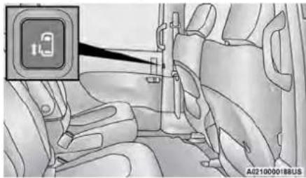
natural_image
Interior view of a car showing seatbelt and passenger seat (no text or symbols visible)PowerSlidingSideDoorSwitch(LeftSideShown)
CHILD PROTECTION DOOR SYSTEM — REAR DOORS
will automati to provide a safer environment for small children n and an in the rear seats, the sliding doors are equipped sufficient Protection Door Lock system
sliding ToEngageTheChildProtectionDoorLock
- Open the sliding side door. common the rear of the sliding door, slide the tection Door Lock control inward (toward the to engage the Child Protection Door Lock.
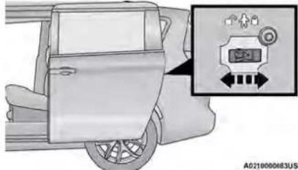
natural_image
Diagram of a car's front door and side panel with an inset showing a digital display (no text or symbols)ChildProtectionDoorLocks
- The inside door handle will not open the sliding down when the Child Protection Door Lock is engaged.
- The power sliding door will operate from the switch in lying just inside the sliding door, regardless of the with Protection Door Lock lever position.
- To avoid unintentional operation of the powers sliding door from therearseats, push the Sliding Door PowerOff button, located in the overhead console.
When the overhead console power off LED is lit, t Child Pro-door may not be power opened or closed vehicle when pushing the buttons just inside the sliding doors, or when pulling on the handles.
WARNING!
Avoid trapping anyone in the vehicle in a collision. Remember that the sliding doors cannot be opened from the inside door handle when the Child Protection Door Locks are engaged.
ToDisengageTheChildProtectionDoorLock
- Open the sliding side door.
- Slide the Child Protection Door Lock control outward (away from the vehicle) to disengage the Child Protection Door Lock.
ding door. 3. Repeat Steps 1 and 2 on the opposite sliding do
NOTE:
After disengaging (or engaging) the Child Protection door Lock, always test the inside door handle with the sliding door closed to make certain the Child Protection door Lock is in the desired position. The inside door handle will open the sliding door when the Child Prot sliding door Lock is disengaged.
If 3. Repeat Steps 1 and 2 on the opposite sliding door. 3. Repeat Steps 1 and 2 on the opposite sliding door
• After engaging the Child Protection Door Lock. • ster farways test the inside door handle with the sliding disengaging (or engaging) the Child Protection warning door closed to make certain the Child Protection door Lock, always test the inside door handle with the sliding door closed to make certain the Child Protection driving. • After disengaging the Child Protection Door Lock is in the locked position. Door Lock is in the desired position. The inside door always test the inside door handle with the sliding door closed to make certain the Child Protection door Lock is disengaged. • door lock is in the unlocked position.
STEERINGWHEEL
TILT/TELESCOPING STEERING COLUMN
This feature allows you to tilt the steering column. This upward or downward. It also allows you to lengthen shorten the steering column. The tilt/telescoping lever is located left of the steering wheel at the end steering column.
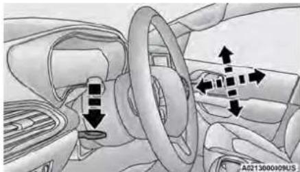
natural_image
Interior view of a car dashboard and steering wheel (no text or symbols visible)Tilt/TelescopingLever
To unlock the steering column, push the lever downward (toward the floor). To tilt the steering column, move the steering wheel upward or downward as desired. To lengthen or shorten the steering column, pull the steering wheel outward or push it inward desired. To lock the steering column in position, put the lever upward until fully engaged.
HEATED STEERING WHEEL — IF EQUIPPED

The steering wheel contains a heating ment that helps warm your hands in weather. The heated steering wheel has one temperature setting. Once the heat
steering wheel has been turned on, it will start the operator turns it off. The heated steering not turn on when it is already warm.
The heated steering wheel button is located w Uconnect system and, if equipped, on the inst panel below the radio. You can access the b through the Climate or Controls menu of the touchscreen.
- Press the heated steering wheel button once down the heating element on.
Press the heated steering wheel button a s time to turn the heating element off.
NOTES
The push engine must be running for the heated steel wheel to operate.
For information on use with the Remote Start see → page 16.
SEATS
Seats are a part of the Occupant Restraint system of the vehicle.
WARNING!
- It is dangerous to ride in a cargo area, inside or outside of a vehicle. In a collision, people riding in these areas are more likely to be seriously injured or killed.
Do not allow people to ride in any area of your vehicle that is not equipped with seats and seat belts. In a collision, people riding in these areas are more likely to be seriously injured or killed. - Be sure everyone in your vehicle is in a seat an using a seat belt properly.
MANUAL ADJUSTMENT (FRONT SEATS) — IF EQUIPPED
WARNING!
- Adjusting a seat while the vehicle is moving is gerous. The sudden movement of the seat could cause you to lose control. The seat belt might be adjusted properly and you could be injured. Adjust the seat only while the vehicle is parke
- Do not ride with the seatback reclined so that shoulder belt is no longer resting against your chest. In a collision you could slide under the belt and be seriously or even fatally injured. The recliner only when the vehicle is parked.
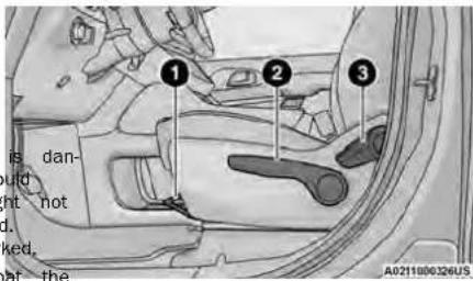
ManualSeatAdjustment
^Use Forward/Rearward Adjustment Handle
2 - Height Adjustment (if equipped)
3-ReclineLever
ManualSeatHeightAdjustment—IfEquipped
The seat height can be raised or lowered by using a lever, located on the outboard side of the seat. Pump the lever upward to raise the seat height or pump the lever downward to lower the seat height.
ManualFrontSeatReclineAdjustment
For models equipped with manual seats, the recline lever is located on the outboard side of the seat. To recline, lean forward slightly, lift the lever and push back to the desired position and release the lever. Let forward and lift the lever to return the seatback to I normal position. Using body pressure, lean forward and rearward on the seat to be sure the seatback has latched.
ManualFrontAdjuster
If equipped with manual front seats, they are able forward or rearward. The manual seat ad handle is located under the seat cushion at edge of each seat.
While sitting in the seat, pull up on the hand, dist-seat forward or rearward. Release the bar was reached the desired position. Then, using a pressure, move forward and rearward on the seat sure that the seat adjusters have latched.
| e and slide | WARNING! |
| once you | |
| Day not ride with the seatback reclined so | |
| shoulder belt is no longer resting against y | |
| to be | |
| In a collision you could slide under the se | |
| which could result in serious injury or deat | |
WARNING!
- Adjusting a seat while driving may be dangerous. Moving a seat while driving could result in loss of control which could cause a collision and serious injury or death.
- Seats should be adjusted before fastening the seat belts and while the vehicle is parked. Serious injury or death could result from a poorly adjusted seat belt.
MANUAL ADJUSTMENT (REAR
SEAT
While sitting in the seat, pull up on the handle to and clside lean forward slightly, lift the lever, and push the seat forward or rearward. Release the bar drack you the desired position and release the lever. Let have reached the desired position. Then, using bodyward and lift the lever to return the seatback to a pressure, move forward and rearward on the seabortal beposition. Using body pressure, lean forward and sure that the seat adjusters have latched. rearward on the seat to be sure the seatback has latched.
WARNING!
- Adjusting a seat while the vehicle is more gerous. The sudden movement of the sea cause you to lose control. The seat belt be adjusted properly and you could be in Adjust the seat only while the vehicle is
- Do not ride with the seatback reclined so that shoulder belt is no longer resting against your chest. In a collision you could slide under the belt and be seriously or even fatally injured, the recliner only when the vehicle is parked.

ManualForward/RearwardAdjustment —QuadSeats(IfEquipped)
ManualRecline—Stow'nGoSeats
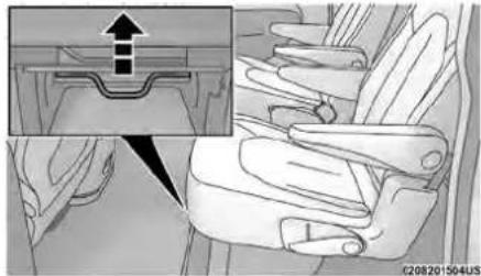
Both second row seats are adjustable forward or rearward. The manual seat adjustment handle is located under the seat cushion at the front edge of each s
natural_image
Diagram of a car seatbelt with an inset showing a mechanical component (no text or symbols present)ManualRearSeatAdjuster
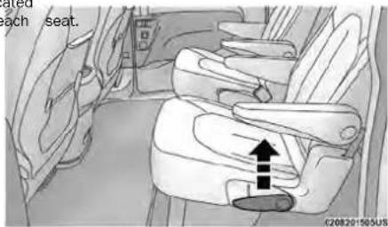
ReclineLever
adjusted Fold-FlatStow'nGoSeats
NOTE:
- You may experience deformation in the seat cushion from the seat belt buckles, or wrinkling of the sea fabric if the seats are left folded for an extended period of time. This is normal and by simply unfolding the seats to the open position, over time the seat cushion may return to its normal shape. Havin an occupant sit in the seat, or massaging the fabi by hand may smooth away any excess wrinkling.
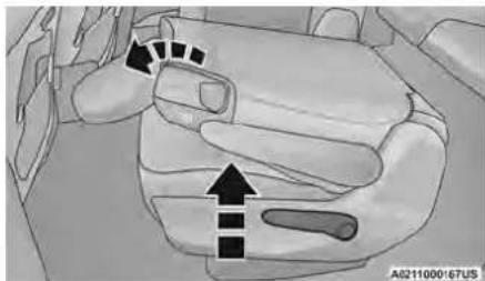
- Permanent wrinkles may still result. To fold the seat, lift the recliner lever to the full up position and push the seatback forward until it rests the seat cushion.
natural_image
Interior view of a car dashboard with directional arrows indicating movement or force (no text or symbols)Fold-FlatSeatReclineLever
EasyEntry
EasyTiltSeat—WithOrWithoutChildSeatInstalled
The second row seats can be tilted forward for entry into the third row with or without a child installed.
- Located in the seatback of the second row lever (or handle for Stow 'n Go seats) that easier access to the third row by tilting the forward.
- Slide the lever upwards, or if equipped, pull handle forward, to unlock the seatback.
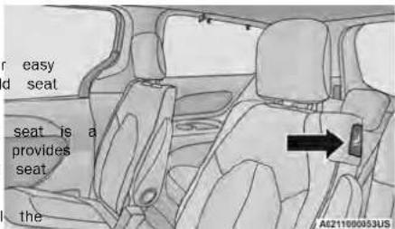
PullEasyTlltSeatHandle(IfEquipped)
NOTE:
- The seatback may lock into the fold-flat position. Use the recline lever to unlock the seatback.
- If equipped with Stow 'n Go seating: when returning the seat to the original position, the headrest must be folded back to the original position.
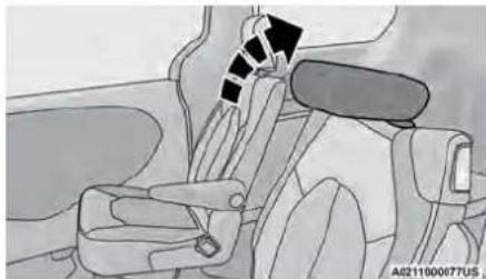
natural_image
Interior view of a car showing seatbelt, dashboard, and steering wheel (no text or symbols visible)Stow'nGoSeatingHeadRestraint
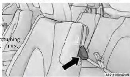
LiftEasyTiltSeatLever(IfEquipped)
- Push on seatback to slide seat forward to access the third row.
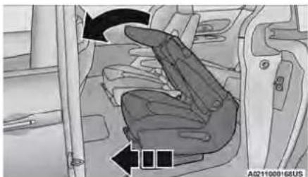
natural_image
Interior view of a vehicle showing a seatbelt mechanism with directional arrows (no text or symbols)EasyTlltSeat
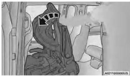
natural_image
Interior view of a car with driver's seat highlighted, showing dashboard and seatbelt (no visible text or symbols)EasyTItWithChildSeatInstalled
- To put the seat back into original position, back on the seatback and lock the seat into position.
WARNING!
Do not use this feature with a child in seat. injury or death may occur.
EasyEntry—WithTheSeatFoldedFlat
The seats can be folded and tilted for more a for passengers to enter and exit the third row.
- Without a child seat installed, you can fold by pulling the recliner handle on the bottom the seat. Before pulling the recliner lever, make the arm rests are folded up.
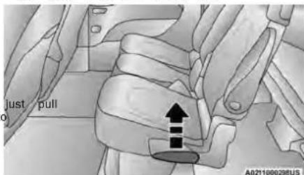
ReclinerLever
Serious
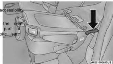
PullStrapForThirdRowPassengers
2
NOTE:
This process is for when there is no child seat insta Use the easy entry lever if a child seat is installed.
ManuallyFoldingThirdRowSeats—IfEquipped
NOTE:
- To put it back into position, pull back on the seat and make sure that it locks into position, pull the seatback toward the back and fold do arm rests.
ExitForThirdRowPassengers—Stow'nGoSeatsOnly
If the second row is equipped with Stow 'n Go, passengers can pull the strap and push the seat ward to fold the seatback down and tilt the seat floor for an easy exit.
You may experience deformation in the seat cushion month the seat belt buckles, or wrinkling of the sea fabric if the seats are left folded for an extended period of time. This is normal and by simply unfolding the seats to the open position, over time the third row. Seat cushion may return to its normal shape. Having an occupant sit in the seat, or massaging the fabric by hand may smooth away any excess wrinkling.
• Permanent wrinkles may still result.
- Lower the center head restraint down to the back by pushing the button on the guide and ing the head restraint down.
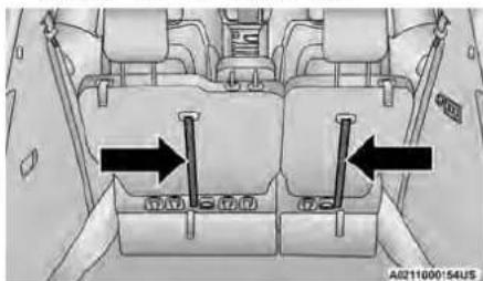
- Pull release strap marked "1" to release the anchors.
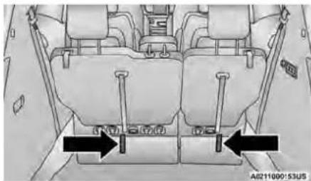
natural_image
Technical diagram of a vehicle seat assembly with two black arrows indicating fastening or clearance points (no text or symbols present)ReleaseStrap"1"
- Pull release strap marked "2" and tumble rearward into the storage bin.
natural_image
Interior view of a vehicle showing seat compartments and directional arrows indicating movement or force (no text or symbols present)ReleaseStrap"2"
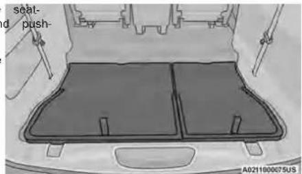
StowedThirdRowSeat
ToUnfoldThirdRowSeats
- Pull up on the assist strap to lift the seats out of the storage bin and push the seat forward until the raise the head restraint to its upright position. anchors latch.
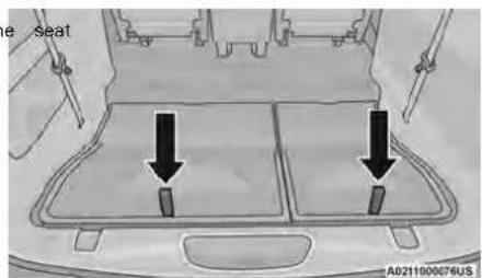
AssistStraps
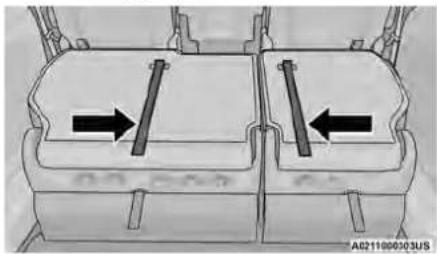
- Pulling strap "2" releases the seatback to return to its full upright position.
natural_image
Technical diagram of a mechanical component with two internal parts and directional arrows indicating movement (no text or symbols)Strap"2"
- In a collision, you or others in your vehicle could injured if seats are not properly latched to their floor attachments. Always be sure the seats are fully latched.
- Sitting in a seat with the head restraint in its lowered position could result in serious injury or death in a collision. Always make sure the head restraints are in their upright positions when the seat is to be occupied.
WARNING!
Stow'nGoSeating
On vehicles equipped with Stow 'n Go seating, the second and third row seats can be folded into the floor for convenient storage.
SECONDROWSTOW'NGO
To stow the seat in the floor, move the front seat all way forward using the manual seat adjustment bar. Move the seatback all the way forward using the recliner handle located on the outboard side of the cushion. Move the seat height to at least mid-position using the height adjuster handle in the outboard side of the cushion.
- To access the storage area, remove the floor mat (if equipped) and place the lock rod in the locked position.
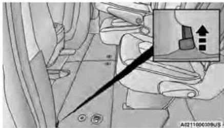
LockRod
- Pull the latch located near the second row catRemove the plastic storage bin from the storage open the floor panel. area, and store in a safe location.
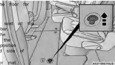
FloorLatch
- Pull the floor panel and position it toward seats while folding the top half down and against the front seats.
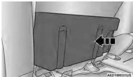
natural_image
Diagram of a car interior showing a seatbelt with a hand holding the seatbelt and a directional arrow indicating movement (no text or symbols present)PushPanelForward
- Fold the armrest upward and stow the seat by grbing the strap on the lower part of the seatback, and guide the seat into the storage area.
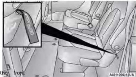
PullStrap
- Push down on the seatback to lock the seat into storage area.
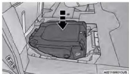
natural_image
Interior view of a vehicle showing a car engine compartment with a black arrow pointing to it (no text or symbols present)PushToLock
NOTE:
○ Push the lock rod inward for the locked position.
○ Pull outward on the lock rod for the unlocked position.
○ For information on storage bin function with the seats rearward page 48.
- Close the floor by pulling the floor panel ba by the bottom corner edge of the panel.
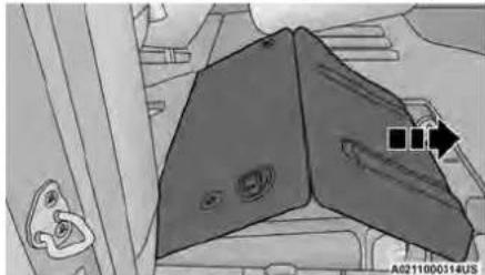
natural_image
Illustration of a mechanical component with no visible text or symbolsExtendFloorPanel
- Push down on floor panel to lock into place
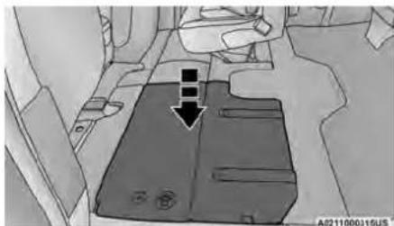
natural_image
Interior view of a vehicle showing a rectangular seat with a black arrow pointing to it, no visible text or symbols.PushToLock
- Readjust the front seat as needed, and replace the floor mat (if equipped).
| In a collision, serious injury could result if storage bin covers are not properly latched:Do not drive the vehicle with the storage open.Keep the storage bin covers closed and while the vehicle is in motion.Do not use a storage bin latch as a t |
CAUTION!
| The storage bin cover must be latched an avoid damage from contact with the front tracks, which have minimal clearance to the |
| Do not sit on the second row seat when stowed position with the seatback upright of wise damage to the seat may occur. |
TOUNSTOWSECONDROWSEATS
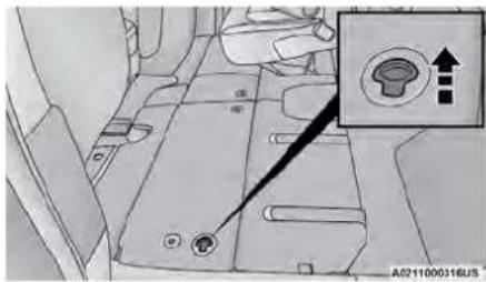
To unstow the seat from the floor, move the front s the allise the way forward using the manual seat adjustment bar. bin covers 1. To access the storage area, remove the floor mat (if equipped) and place the lock rod in the locked latched position.
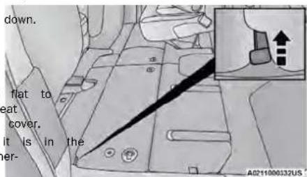
LockRod
NOTE:
- Push the lock rod inward for the locked position. - Pull outward on the lock rod for the unlocked position.
- Pull the latch located near the second row open the floor panel.
FloorLatch
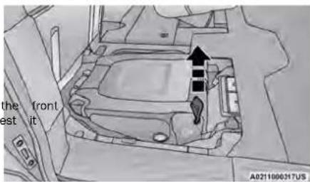
- Pull the floor panel and position it toward seats while folding the top half down and against the front seats.
natural_image
Diagram of a mechanical component with a black arrow pointing to a section, no visible text or symbolsPushPanelForward
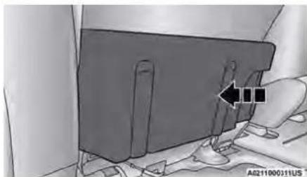
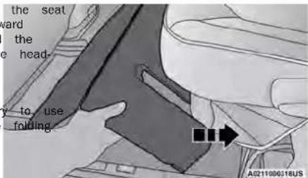
4seaPullo the strap located on the seat and pull the seat out of the storage area. Push the seat rearward making sure that it locks into the floor. Fold the seatback into the upright position and pull the head-rest up.
NOTE:
If the seatback is locked, it will be necessary the recliner handle to unlock the back before into the upright position.
PullStrap
- Replace the plastic storage bin into the storage area.
- To position the floor panel back into its original state, grab the bottom corner and extend it outward.
ExtendPanel
- Lay the floor panel flat and push down until it is into position.
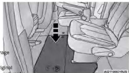
PushDownToLock
- Readjust the front seat as needed, and replace the floor mat (if equipped).
WARNING!
- In a collision, you or others in your vehicle injured if seats are not properly latched to floor attachments. Always be sure the seats fully latched.
- Sitting in a seat with the head restraint in ered position could result in serious injury or in a collision. Always make sure the head restraints are in their upright positions when seat is to be occupied.
POWER ADJUSTMENT (FRONT SEATS) — IF EQUIPPED
Some models may be equipped with an eight-way seat for the driver. The power seat switches are the outboard side of the seat. The switches cont movement of the seat cushion and the seatback.
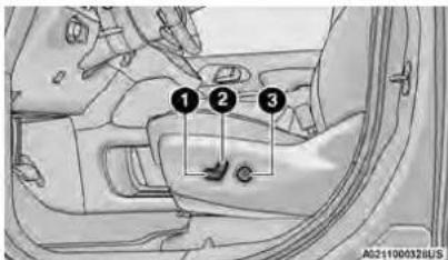
DriverPowerSeatSwitches
1 - Seat Switch
2 - Seatback Switch
3 - Lumbar Switch
WARNING!
ou adjusting a seat while driving may be da
their Moving a seat while driving could result
re control which could cause a collision and
injury or death.
is low seats should be adjusted before fastening, death and while the vehicle is parked. Se injury or death could result from a poor, the seat belt.
- Do not ride with the seatback reclined shoulder belt is no longer resting against chest. In a collision you could slide under belt, which could result in serious injury
power
I the
CAUTION!
Do not place any article under a power s impede its ability to move as it may caus the seat controls. Seat travel may become movement is stopped by an obstruction in path.
AdjustingTheSeatForwardOr Rearward
The seat can be adjusted both forward and using the seat switch. The seat will move tion of the switch. Release the switch when position has been reached.
AdjustingTheSeatUpUpDown
The height of the seats can be adjusted up or down. In order, up, upward or push downward on the rear of seat in switch of the seat will move in the direction of the swing release the switch when the desired position has been reached.
the seat terious TiltingTheSeatUpUpDown
The angle of the seat cushion can be adjusted in two directions. Pull upward or push downward on the front to that the seat switch, the front of the seat cushion will you move in the direction of the switch. Release the swit or the one of the desired position has been reached.
RecliningTheSeatback
The angle of the seatback can be adjusted forward or rearward. Push the seatback switch forward or rearward, the seat will move in the direction of the swit seat. Release the switch when the desired position is desired to
limited if
WARNING!
- Adjusting a seat while driving may be dangerous. Moving a seat while driving could result in loss of control which could cause a collision and serious injury or death.
Sears by should be adjusted before fastening the seat the bell rec and while the vehicle is parked. Serious the injured or death could result from a poorly adjusted seat belt. - Do not ride with the seatback reclined so that the shoulder belt is no longer resting against your chest. In a collision you could slide under the sea belt, which could result in serious injury or death.
CAUTION!
Do not place any article under a power se impede its ability to move as it may cause the seat controls. Seat travel may become I movement is stopped by an obstruction in t path.
PowerLumbar—IfEquipped
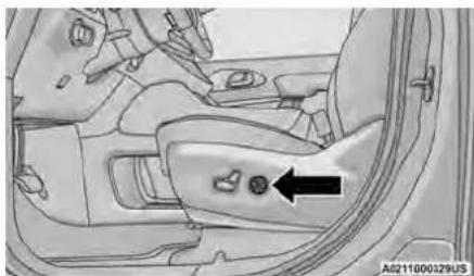
natural_image
Interior view of a car showing the dashboard and seat area with a black arrow pointing to a button (no text or symbols present)PowerLumbarSwitchLocation
HEATED SEATS
FrontHeatedSeats—IfEquipped
The damage to limit the front heated seats control buttons located in the touchscreen.
You can choose from HI, LO or off tings. The indicator lights in each swi cate the level of heat in use. Two indicator illuminate for HI, one for LO and none for o
- Press the heated seat button once to turn setting on.
- Press the heated seat button a second tim the LO setting on.
- Press the heated seat button a third time heating elements off.
The level of heat selected will stay on until changes it.
NOTE:
- Once a heat setting is selected, heat will within two to five minutes.
- The engine must be running for the heated operate.
aFofourInformation on use with the Remote Start located page 16.
The front driver's seat may be equipped with a four-formation lumbar adjustment. The power lumbar switch is located page 16.
on the outboard side of the equipped power seat. Push the switch forward or rearward to increase or decrease
the lumbar support. Push the switch upward or down-
ward to raise or lower the lumbar support.
WARNING!
- Persons who are unable to feel pain to because of advanced age, chronic illness, tes, spinal cord injury, medication, alcohol
exhaustion or other physical condition mus at case care when using the seat heater. It incl burns even at low temperatures, especially nts for long periods of time. - Do not place anything on the seat or some insulates against heat, such as a blanket ion. This may cause the seat heater to bring in a seat that has been overheat cause serious burns due to the increased temperature of the seat.
HEAD ^® RESTRAINTS
Head restraints are designed to reduce the risk of in by restricting head movement in the event of a rear impact. Head restraints should be adjusted so that the top of the head restraint is located above the top of your ear. seats to
WARNING!
- All occupants, including the driver, should ate a vehicle or sit in a vehicle's seat head restraints are placed in their proper in order to minimize the risk of neck in event of a crash.
not oper- until the positions
(Continued)
WARNING!
- Head restraints should never be adjusted while vehicle is in motion. Driving a vehicle with the restraints improperly adjusted or removed could cause serious injury or death in the event of collision.
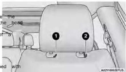
FrontHeadRestraInt
natural_image
Mechanical assembly diagram showing a belt switch mechanism (no text or symbols present)ForwardAdjustment
HeadRestraints—FrontSeats
The front driver and passenger seats are equipped four-way head restraints.
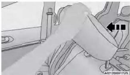
To raise the head restraint, pull upward on the head restraint. To lower the head restraint, push the adjustment button, located at the base of the head restraint. Release Button and push downward. The front head restraints are also Adjustment Button
adjustable forward and rearward. To tilt forward, pull the top of the head restraint toward the front of the vehicle to the desired position. To adjust the head restraint rearward, continue pulling forward on the top of the head restraint to the farthest forward position and the head restraint will return to the upright position.
NOTE:
To remove the head restraint, raise it as far as it can. Then, push the release button and the adjustment button at the base of each post while pulling the head restraint up. Seatback angle may need to be adjusted to fully remove the head restraint. To reinstall the head restraint, put the head restraint posts into the holes and push downward. Then, adjust the head restraint to the appropriate height.
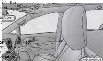
NormalPosition
WARNING!
- A loose head restraint thrown forward in a collision or hard stop could cause serious injury or death to occupants of the vehicle. Always securely stow removed head restraints in a location outside the occupant compartment.
- ALL the head restraints MUST be reinstalled in the vehicle to properly protect the occupants. Follow the preceding reinstallation instructions prior to operating the vehicle or occupying a seat.
HeadRestraints—SecondRowStow'n GoSeats
NOTE:
If equipped with Stow 'n Go sealing, the head restraint are non-adjustable and non-removable. Donotpull on non-adjustable head restraints when folding the seat. For information on child seat tether routing, see page 147.
HeadRestraints—ThirdRow
The outboard head restraints can be manually forward for improved rearward visibility. Pull the strap to fold them forward.
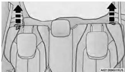
natural_image
Diagram of car interior showing dashboard and seat compartments with directional arrows indicating movement (no text or symbols)ReleaseStraps
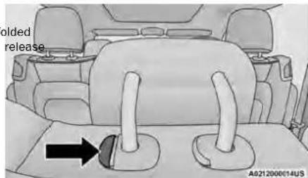
AdjustmentButton
when
BASIC VOICE COMMANDS
The following basic Voice Commands can be given at any point while using your Uconnect system.
Push the VR buttonor say the vehicle's Wake Up word, "Hey Uconnect". The factory default Wake up word is set to "Hey Uconnect" and can be programmed through the Uconnect Settings. After the beep, say:
- "Cancel" to stop a current voice session.
- "Help" to hear a list of suggested Voice Commands
- "Repeat" to listen to the system prompts again.
Notice the visual cues that inform you of your Voice Recognition system's status.
UsethisQRcodetoaccessyourdigital
experience.
NOTE:
- The head restraints must be raised manually occupying the third row.
- Do not fold if there are passengers seated third row seats.
The head restraint in the center position can and lowered for tether routing or height adjust page 129.
UconnectVoiceRecognition—IfEquipped
INTRODUCING VOICE RECOGNITION
NOTE:
To remove the center head restraint, raise it can go. Then, push the release button and ment button at the base of each post while head restraint up. To reinstall the head restraint
the head restraint posts into the holes and push downward. Then, using the adjustment button, adjust the head restraint to the appropriate height.
Start using Uconnect Voice Recognition (VR) with adjust- helpful quick tips. It provides the key Voice Co puning the and tips you need to know to control your sy
GET STARTED
The uAR button is used to activate/deactivate your Voice Recognition system.
Helpful hints for using Voice Recognition:
- Reduce background noise. Wind noise and passenger conversations are examples of noise that may impact recognition.
these Speak clearly at a normal pace and volume while demands leading straight ahead.
- Each time you give a Voice Command, first push t VR button, wait until after the beep, then say your Voice Command. You can also say the vehicle "Wak Up" word and state your command.
- A passenger can press the VR button shortcutFopn Uconnect system support, call 1-877-855-8400 the radio status bar to also issue a command(24 hours a day 7 days a week) or visit
- You can interrupt the help message or systemDriveUconnect.com (US) or DriveUconnect.ca (Canada)
prompts by pushing the VR button and saying Voice Command or saying the vehicle's "Wake" word and saying a command from the current category.
MIRRORS
PILLUMINATED VANITY MIRRORS — a).IF EQUIPPED
To access an illuminated vanity mirror, flip down one the visors and lift the cover.
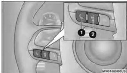
UconnectVoiceCommandButtons
INSIDE REARVIEW MIRROR
ManualMirror
A single ball joint mirror is used to allow the driver to adjust up, down and left, right. The mirror should be adjusted to center on the view through the rear window.
Headlight glare can be reduced by moving the small control under the mirror to the night position (toward the rear of the vehicle). The mirror should be adjusted while set in the day position (toward the windshield).
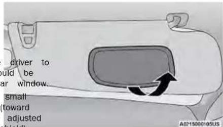
IlluminatedMirror
1 - Push To Answer An Incoming Phone Call
2 — For Vehicles Equipped With Navigation: Push The
Voice Recognition Button To Begin Radio, Media, Navigation, Climate, Start Or Answer A Phone Call, And Send Or Receive A Text
2 — For Vehicles Not Equipped With Navigation: Push The Phone Button To Answer An Incoming Phone Call
ADDITIONAL INFORMATION
© 2023 FCA US LLC. All rights reserved. Mopar and Uconnect are registered trademarks and Mopar Owner Connect is a trademark of FCA US LLC. SiriusXM® and all related marks and logos are trademarks of SiriusXM® Radio Inc page 231.
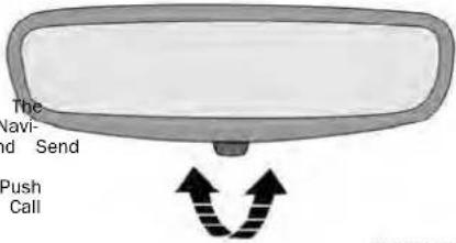
ManualRearviewMirror
OUTSIDE MIRRORS
The outside mirror(s) can be adjusted to the center of the adjacent lane of traffic to achieve the optimal vie
WARNING!
Vehicles and other objects seen in an outside convex mirror will look smaller and farther away than they really are. Relying too much on side convex mirrors could cause you to collide with another vehicle or other object. Use your inside mirror when judging the size or distance of a vehicle seen in a side convex mirror.
CONVERSATION MIRROR
Located in the overhead console there is a conversation mirror to view all the passengers in the vehicle. Push the panel to release the drop down mirror. Raise the mirror and push to latch it back in the stowed position.
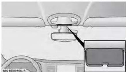
natural_image
Interior view of a car showing the dashboard and steering wheel (no text or symbols visible)ConversationMirror
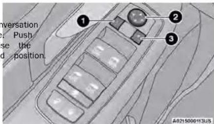
PowerMirrorControls
1 - Left Mirror Select
2 - Mirror Control Switch
3 - Right Mirror Select
OUTSIDE MIRRORS FOLDING FEATURE
All outside mirrors are hinged and may be moved eiti forward or rearward to resist damage. The hinged two detent positions:
• Full forward position
• Full rearward position
2
HEATED MIRRORS — IF EQUIPPED

These mirrors are heated to melt frost or ice. This feature will be activated whenever you turn on the rear window defroster (if equipped) page 42.
LIGHTINGOPERATION
POWER MIRRORS — IF EQUIPI
The power mirror controls are located on the door trim panel.
The power mirror controls consist of mirror seletons and a four-way mirror control switch. To
mirror, push either the L (left) or R (right) to mirror that you want to adjust.
NOTE:
A light in the selected button will illuminate indi the mirror is activated and can be adjusted. Using the mirror control switch, push on any of arrows for the direction that you want the mirror move.
MULTIFUNCTION LEVER
The multifunction lever is located on the left side of steering column. The multifunction lever controls the turn signals, headlight high/low beams, and flash-to-pass functions.
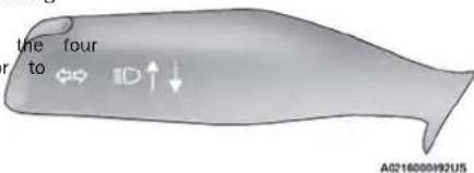
MultifunctionLever
HEADLIGHT SWITCH
The headlight switch is located on the left side of the instrument panel. The switch controls the operation of the headlights, parking lights, instrument panel lights, and interior lights.
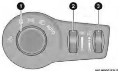
HeadlightSwitch
1 - Rotate Headlight Control
2 - Ambient Light Dimmer Control
3 - Instrument Panel Dimmer Control
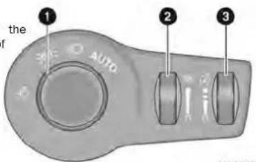
HeadlightSwitch(VehiclesSoldInCanadaOnly)
1 - Rotate Headlight Control
2 - Ambient Light Dimmer Control
3 - Instrument Panel Dimmer Control
NOTE:
Vehicles sold in Canada are equipped with a headlight lights will automatically deactivate when the front switch with an AUTO and ON detent but without top lights are turned on.
detent. Headlights will be deactivated when the head-allowed by law in the country in which the veh light switch is placed in the parking lights position was purchased, the Daytime Running Lights can be ever, the Daytime Running Lights (DRLs) will be turned on and off using the Uconnect system vated along with the front and rear marker lights. The page 100.
DRLs may be deactivated when the parking brake is engaged. - On some vehicles, the Daytime Running Lights may decrease or reduce intensity on one side of the
From the O (off) position, rotate the headlight switch. Vehicle (when a turn signal is activated on that clockwise to the first detent for parking lights and side), or on both sides of the vehicle (when the instrument panel lights operation. Rotate the headlight warning lights are activated).
switch to the second detent for headlights, parking lights and instrument panel operation.
NOTE:
For vehicles sold in Canada, rotate the headlight switch clockwise from the parking light and instrument panel light position to the first detent to turn on the headlights also. Rotate to the second detent, AUTO position to turn on automatic headlights, parking lights, and instrument panel lights.
DAYTIME RUNNING LIGHTS (DRLS) — IF EQUIPPED
The headlights or LED light bars on your vehicle will illuminate when the engine is started. This provides a constant lights on condition until the ignition is placed in the OFF position. If the parking brake is applied, Daytime Running Lights (DRLs) will turn off.
NOTE:
- For vehicles sold in Canada, the Daytime Running headlight lights will automatically deactivate when the front fog lights are turned on.
head- allowed by law in the country in which the veh ition was purchased, the Daytime Running Lights can be turned on and off using the Uconnect system nts. The page 100.
- On some vehicles, the Daytime Running Lights may deactivate, or reduce intensity, on one side of the switch vehicle (when a turn signal is activated on that side), or on both sides of the vehicle (when the award warning lights are activated).
King
To activate the delay feature, place the ignition TurnSignalWarning
Push the multifunction lever toward the instrument to switch the headlights to high beams. Pulling off. If the headlights or parking lights are traveled for about 1 mile (1.6 km) with a turn signal, the multifunction lever back will turn the low beam of back on or the ignition is placed in the ON cluster to alert the driver.
FLASH-TO-PASS
When exiting the vehicle the driver can choose to LANE CHANGE ASSIST — lights headlights remain on for 30, 60, or 90 seconds or this remain on. You can change the timer setting IF EQUIPPED
You can signal another vehicle with your headlights remain on for 30, 60, or 90 seconds or lightly pulling the multifunction lever toward you. This remain on. You can change the timer setting if EQUIPPED will cause the high beam headlights to turn on through the Uconnect syste mpage 100. Tap the multifunction lever up or down once, without remain on, until the lever is released. If the headlights are turned off before the ignition of they beyond the detent, and the turn signal (right will turn off in the normal manner. left) will flash three times then automatically turn off.
AUTOMATIC HEADLIGHTS — IF EQUIPPED
NOTE:
Tap the multifunction lever up or down once, without iomvintgeybeyond the detent, and the turn signal (right left) will flash three times then automatically turn off.
This system automatically turns your headlights on placing the ignition in the OFF position to activate the feature provides battery protection to avoid wearing down the battery if the headlights or parking light are left on for extended periods of time when the ignition is in the OFF position. After eight minutes of the ignition being in the OFF position and the headlight switch, turn the headlight switch to the driver's door is opened. The battery protection feature will be disabled if the ignition is placed in any position other than OFF during the lead off, move the headlight switch out of the AUTO button.
NOTE:
Move the multifunction lever up or down to activate eight minute delay.
The engine must be running before the headlights will cluster flash to show proper operation. come on in the Automatic mode.
If either light remains on and does not flash, or there is a very fast flash rate, check for a defective outside light bulb.
This feature provides the safety of headlight illumination for up to 90 seconds after exiting your vehicle.
INTERIORLIGHTS
INTERIOR COURTESY LIGHTS
The courtesy light switches are used to turn tesy lights on/off.
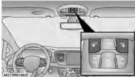
natural_image
Interior view of a car dashboard and steering wheel (no visible text or symbols)CourtesyLightSwitches
To operate the courtesy lights, push either the passenger light switch.
RearCourtesy/ReadingLights—IfEquipped
Located above the rear passengers are courtesy/reading lights. The lights turn on when a front door, sliding door or the liftgate is opened. If your vehicle equipped with Remote Keyless Entry (RKE) the lights will also turn on when the unlock button on the ke is pushed.
The courtesy lights also function as reading lights. Push the lens to turn these lights on while inside the vehicle. Push the lens a second time to turn each light off.
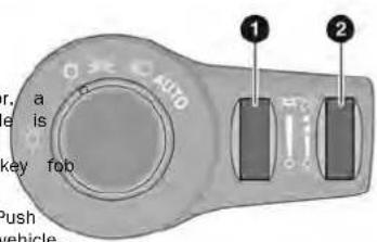
A0216000255US
DimmerControls
DimmerControls
The dimmer controls are part of the headlight switch, Ambient Light Dimmer Control and are located on the driver's side of the instrument panel.
With the parking lights or headlights on, rotating the right dimmer control upward will increase the brightness of the instrument cluster lights. Rotating the left dimmer control will adjust the interior light levels of driver or ambient lighting on the instrument panel and doors.
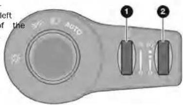
A0216000256US
DimmerControls(VehiclesSoldInCanadaOnly)
NOTE:
- Before exiting the vehicle, make sure that the interior lights are turned off. This will prevent the battery from discharging once the doors are closed.
- If a light is left on, it will automatically be turned off approximately 10 minutes after the ignition is in the OFF position.
1 - Ambient Light Dimmer Control
2 - Instrument Panel Dimmer Control
At the top delent of the instrument panel dimmer, all the interior lights will illuminate. At the bottom most setting (extreme bottom) interior lights are turned off (dome off), and the cluster, radio and instrument lighting go to their lowest dimmable setting.
WINDSHIELDWIPER&WASHERS
The windshield wiper/washer controls are located on the right side of the steering column. The front wipers are operated by rotating a switch, located on the end of the lever.
The wipers and washers are operated by a switch with For Front Washer the wiper lever. Rotate the switch at the end of the Roter for Rear Wiper Operation upward, to the first detent past the intermittent 3 settings for low-speed wiper operation. Rotate the switch at the end of the lever upward to the second detent past the Push Up For Mist
Intermittent settings for high-speed wiper operation. To turn the windshield wipers off, rotate the switch within the lever all the way down to OFF. Always
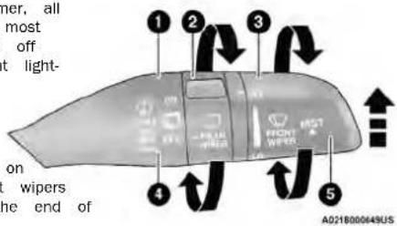
WasherAndWiperControls
itch - win For Front Washer
2 of the Rotate For Rear Wiper Operation
3 setting Rotate For Front Wiper Operation
4 at the Push Forward For Rear Washer
5 past Push Up For Mist
NOTEin
Always remove any buildup of snow that prevents the lever upward to the MIST position and release windshield wiper blades from returning to the off-post-single wiping cycle.
tion. If the windshield wiper switch is turned off and the
blades cannot return to the off position, damage No wiper motor may occur.
WARNING!
Sudden loss of visibility through the windshield lead to a collision. You might not see other other obstacles. To avoid sudden icing of the shield during freezing weather, warm the winds with the defroster before and during windshield washer use.
IntermittentWipers
Use the intermittent wiper when weather conditions make a single wiping cycle with a variable pause between cycles desirable. Rotate the switch at the end of the wiper lever to the first detent position, then turn the switch at the end of the lever to desired delay interval. There are four delay segments which allow you to regulate the wipe interval from a minimum of one cycle every second to a maximum or approximately 36 seconds between cycles. The delay intervals will double in duration when the vehicle speed is 10 mph (16 km/h) or less.
WindshieldWashers
To use the washer, pull the lever rearward toward you and hold. If the lever is pulled while on the intermit setting, the wipers will turn on and operate for several wipe cycles after the lever is released, and then resu the intermittent interval previously selected. If the lever is pulled while the wipers are in the off position, the wipers will operate several cycles, then turn off.
Mist
push the lever upward to the MIST position and release for post-single wiping cycle.
f and the
NOTE:the
The Mist feature does not activate the washer pump; therefore, no washer fluid will be sprayed on the wind shield. The washer function must be used in order to spray the windshield with washer fluid.
could for information on wiper care and replacement, see vehicles page or 191.
RAIN SENSING WIPERS — IF EQUIPPED
This feature senses rain or snowfall on the winds and automatically activates the wipers. Rotate the of the windshield wiper lever to one of the four positions to activate this feature.
The sensitivity of the system is adjustable from the windshield wiper lever. Wiper sensitivity position 1 the least sensitive, and wiper sensitivity position 4 the most sensitive.
NOTE:
- The Rain Sensing feature will not operate when wiper switch is in the low or high position.
- The Rain Sensing feature may not function prop when ice or dried saltwater is present on the windshield.
- Use of products containing wax or silicone may reduce rain sensor performance.
- The Rain Sensing feature can be turned on through the Uconnect systempage 100.
The Rain Sensing system has protective features wiper blades and arms. It will not operate under following conditions:
- LowTemperatureWipeInhibit— The Rain Sensing feature will not operate when the ignition is placed in the ON position, when the vehicle tionary and the outside temperature is below (0°C), unless the wiper control on the windshield wiper lever is moved, the vehicle speed becon greater than 3 mph (5 km/h) or the outside perature rises above freezing.
- NeutralWipeInhibit— The Rain Sensing feature will not operate when the ignition is ON, when the mission gear selector is in the NEUTRAL position and the vehicle speed is less than 3 mph unless the wiper control on the windshield which is moved, the vehicle speed is greater than 3 mph (5 km/h) or the gear selector is more than the NEUTRAL position.
• RemoteStartModelInhibit— On vehicles equipped with the Remote Start system, Rain Sensing were not operational when the vehicle is in the Remote Start mode. Once the operator is in vehicle and has placed the ignition switch in ON/RUN position, rain sensing wiper operation to resume, if it has been selected, and no other conditions (mentioned previously) exist.
operly REAR WIPER AND WASHER
The rear wiper/washer is operated by rotating a located at the middle of the lever.
Rotate the center portion of the lever upward to the first detent for intermittent operation and to the second detent for continuous rear wiper operation.
for the RearWindowWasherOperation r the
Pushing the windshield wiper lever forward activates the rear window washer. If the is pushed while on the intermittent setting the wiper will turn on and operate for
wipe cycles after the lever is released, and then 32°F the intermittent interval previously selected. If the yield is pushed while the wiper is in the off position mes wiper will operate several wipe cycles, then turn tem-
CLIMATECONTROLS the trans-
MANUAL CLIMATE CONTROL DESCRIPTIONS AND FUNCTIONS
Switch Connect5With7-InchDisplayManualTemperature Controls
Uconnect5/5NAVWith10.1-inchDisplayManual TemperatureControls
MAXA/CButton

Press and release the MAX A/C button change the current setting. The indicator illuminates when MAX A/C is on. Perfor this function again will cause the MAX
operation to switch into manual mode and the indicator will turn off.
NOTE:
The MAX A/C setting is only available on the touchscreen.
A/CButton

Press and release the A/C button to the current setting. The indicator illuminates when A/C is on.
NOTE:
- For Manual Climate Controls, if the system is then recirculation mode is not allowed in Defrost Floor or Defrost Mode, the A/C can be turned off to improve window clearing operation. Recirculation but the A/C system shall remain active to prevent fogging of the windows.
- If fog or mist appears on the windshield or LED in the control button to blink, and then tu
On systems with Manual Climate Controls (if equi in Mix the Recirculation mode is not allowed in Defrost ed off to improve window clearing operation. Recirculation prevent disabled automatically if this mode is selected. Al ing to use Recirculation while in this mode caus LED in the control button to blink, and then tu
glass, select Defrost mode, and increase blow speed if needed.
- If your air conditioning performance seems low than expected, check the front of the A/C c (located in front of the radiator), for an acc tion of dirt or insects. Clean with a gentle spray from the front of the radiator and three condenser.
RecirculationButton

Press and release this button to change system between recirculation mode and side air mode. The Recirculation indicator and the A/C indicator illuminate when the
RAA Cuation button is pressed. Recirculation can be used when outside conditions such as smoke, od dust, or high humidity are present. Recirculation is used in all modes except for Defrost. Recirculation be unavailable (button on the touchscreen grayed if conditions exist that could create fogging on the inside of the windshield. The A/C (Air Conditioning) be deselected manually without disturbing the mode
control selection. Continuous use of the Recirculat change may make the inside air stuffy and wind going may occur. Extended use of this mode is omnended. Recirculation mode may automatically adjust to optimize customer experience for warmer cooling, dehumidification, etc.
FrontDefrostButton

Press and release the Front Defrost but to change the current airflow setting to Defrost mode. The indicator illuminates
FRONT when this feature is on. Air comes from the windshield and side window demist outlets. When the defrost button is selected, the blower level may increase. Use Defrost mode with maximum temperature settings for best windshield and side window defrosting and defogging. Performing this function will
cause the Automatic Temperature Control (ATC) to switch into manual mode. If the Front Defrost mode is turned off the climate system will return the previous out-setting.
RearDefrostButton

Push and release the Rear Defrost button to turn on the rear window defroster and the heated outside mirrors (if equipped). An indicator will illuminate when the rear defroster is on. The rear window defroster auto turns off after 15 minutes.
CAUTION!
w fog
Failure_C -to follow these cautions can cause damage to the heating elements:
Use care when washing the inside of the rear window. Do not use abrasive window cleaners on the interior surface of the window. Use a soft cloth and a mild washing solution, wiping parallel to the mode heating elements. Labels can be peeled off after soaking with warm water.
es Do not use scrapers, sharp instruments, or abra-
rn sior. window cleaners on the interior surface of the
window.
- Keep all objects a safe distance from the window.
FrontTemperatureControl
These buttons provide the driver and passenger independent temperature control.

Push the red button on the faceplate or touchscreen or press and slide the temperature bar towards the red arrow button touchscreen for warmer temperature
settings.

Push the blue button on the faceplate touchscreen or press and slide the tem ture bar towards the blue arrow button the touchscreen for cooler temperature
settings.
BlowerControl

Blower Control is used to regulate the amount of air forced through the Clim Control system. There are seven blower speeds available. The speeds can be
selected using either the blower control knob faceplate or the buttons on the touchscreen.
- Faceplate: The blower speed increases as you or the blower control knob clockwise from the general blower setting. The blower speed decreases on turn the blower control knob counterclockwise
- Touchscreen: Use the small blower icon to red the blower setting and the large blower icon increase the blower setting. Blower speed can be selected by pressing the blower bar area between the icons.
Bi-LevelMode

Air comes from the instrument panel outlets and floor outlets. A slight amount of air is directed through the defrost and side window demister outlets.
the NOTE:
Bi-Level mode is designed under comfort conditions to provide cooler air out of the panel outlets and warm air from the floor outlets.
FloorMode

Air comes from the floor outlets. A slight amount of air is directed through the defrost and side window demister outlets.
SYNCButton

Press the SYNC button on the touchscre to toggle the Sync feature on/off. The indicator is illuminated when this feature enabled. SYNC is used to synchronize th
front and rear passenger temperature settings with driver temperature setting. Changing the front or passenger temperature setting while in SYNC will matically exit this feature. Pressing SYNC on the screen while in the Front Climate screen synchro the driver and passenger temperatures only. In o SYNC rear temperature to driver temperature, the touchscreen must be on the Rear Climate screer
ModeControl
MODE The airflow distribution mode can be adjusted so air comes from the instrun panel outlets, floor outlets, defrost outlet and demist outlets.
Faceplate: Push the button in the center of the比重ge the airflow distribution mode.
Touchscreen:Select Mode by pressing one of the Buttons on the touchscreen.
MixMode

Air is directed through the floor, defrost, and side window demister outlets. This setting works best in cold or snowy conditions that require extra heat to the windshield. This is good for maintaining comfort while reducing on the windshield.
Mode ClimateControlOFFButton

Press and release this button to turn the Climate Control ON/OFF.
NOTE:
The SYNC setting is only available on the touch
PanelMode
Air comes from the outlets in the inst panel. Each of these outlets can be in ally adjusted to direct the flow of air. vanes of the center outlets and outboa
outlets can be moved up and down or side to side to regulate airflow direction. There is a shut-off wheel located below the air vanes to shut off or adjust the amount of airflow from these outlets.
ControllingTheRearClimateControls FromTheFrontMTCDisplay/
Touchscreen
The Three-Zone Manual Temperature Control (MTC) system allows for adjustment of the rear climate trols from the front MTC display/touchscreen.
Tochangetherearsystemsettings:
- Press the Rear Climate button on the touch display the rear climate controls. The control tions now operate the rear system.
- Press the Front Climate button on the to return to the front climate controls.
REARCLIMATECONTROLBUTTON
The image is too blurry to recognize any text content.
REAR CLIMATE
Press and release this button to accre rear climate controls. The indicator will minute when the rear climate controls on.
REARLOCKBUTTON
- 2017年
LOCK REAR
Press and release this button to lock rear manual temperature controls from adjusting the rear temperature and bid settings.
FRONTCLIMATEBUTTON
The image is too blurry to recognize any text content.
FRONT CLIMATE
Press and release this button to chair display on the Uconnect system back Front Climate Controls.
REARTEMPERATURECONTROL
These buttons provide the rear passengers with pendent temperature control.


Push the up arrow button on the touch screen to increase the temperature.
Push the down arrow button on the to screen to decrease the temperature.

NOTE:
When the SYNC feature is active, the passenger' perature moves up and down with the driver's temperature.
the SYNCBUTTON

Press the SYNC button on the touchscreen to toggle the SYNC feature on/off. The indicator is illuminated when this feature enabled. SYNC is used to synchronize the
front trend rear passenger temperature settings with driver temperature setting. Changing the front or passenger temperature setting while in SYNC exits feature.
NOTE:
TheSYNC setting is only available on the touch on the BLOWERCONTROL

Blower Control is used to regulate the amount of air forced through the Climate Control system. There are seven blower speeds available. Adjusting the blower
causes automatic mode to switch to manual operation. The speeds can be selected using the buttons on the touchscreen.
PANELMODE

Press this button on the touchscreen to change the air distribution mode to Panel Mode. In Panel Mode, air comes from the outlets in the headliner. Each of the
lets can be individually adjusted to direct the Moving the air vanes of the outlets to one off the airflow.
2
BI-LEVELMODE

Press this button on the touchscreen to change the air distribution mode to Bi-Level Mode. In Bi-Level Mode, air comes from the headliner outlets and floor outlets.
NOTE:
Bi-Level Mode is designed under comfort conditions to provide cooler air out of the panel outlets and warm air from the floor outlets.
FLOORMODE

Press this button on the touchscreen to change the air distribution mode to Floor Mode. In Floor Mode, air comes from the floor outlets.
REARPASSENGERCLIMATECONTROLOFF
BUTTON screen.

Press and release this button to turn the Rear Climate Controls off.
RearManualTemperatureControl(MTC)
The rear Manual Temperature Control (MTC) system floor air outlets at the rear right side of the 1 seats and overhead outlets at each outboard rea ing position. The system provides heated air through the floor outlets or cool, dehumidified air through headliner outlets.
The rear system temperature control buttons are located on the headliner on the passenger side vehicle.
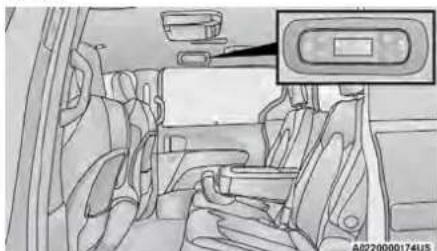
natural_image
Interior view of a car showing seats and rearview mirror (no text or symbols visible)RearManualClimateControls
CAUTION!
Interior air enters the Rear Automatic Temperature Control system through an intake grille, located floor under the passengers' seats. Do not block place objects directly in front of the inlet grille heater outlets. The electrical system could overload causing damage to the blower motor.
REARTEMPERATURECONTROL

Push the up arrow button to raise the perature. The rear temperature settings displayed in control head.

Push the down arrow button to lower temperature. The rear temperature setting are displayed in control head.
REARBLOWERCONTROL

The rear blower control can be manual to off, or any fixed blower speed by the blower control buttons. This allows rear seat occupants to control the volu
air circulated in the rear of the vehicle. The two icons increases blower speed, whereas the of the two icons decreases the blower speed.
REARMODECONTROL

Push this button on the Rear Climate trols to change the air distribution mod the rear passengers.
PANELMODE

Air comes from the outlets in the heat. Each of these outlets can be individual adjusted to direct the flow of air. Mov air vanes of the outlets to one side airflow.
BI-LEVELMODE

Air comes from both the headliner outlets and the floor outlets.
the NOTE:
In many temperature positions, the Bi-Level mode is designed to provide cooler air out of the headliner outlets and warmer air from the floor outlets.
FLOORMODE
lv set
Air comes from the floor outlets.

the
To manually set the rear blower controls to off, press the Rear Climate Control/Blower Off button.
CLIMATE VOICE COMMANDS
Adjust vehicle temperatures hands-free and keep everyone comfortable while you keep moving ahead (If vehicle is equipped with climate control).
Push the VR button on the steering wheel. After the vrep, the say one of the following commands:
will " shut Set driver temperature to 70 degrees"
- "Set passenger temperature to 70 degrees"
Did you know: Voice Command for Climate may only be used to adjust the interior temperature of your vehicle. Voice Command will not work to adjust the heated seats or steering wheel if equipped.
OPERATING TIPS
Refer to the chart at the end of this section gested control settings for various weather condi
SummerOperation
The engine cooling system must be protected high-quality antifreeze coolant to provide proper sion protection and to protect against engine overheating.
WinterOperation
To ensure the best possible heater and defrost mance, make sure the engine cooling system in tioning properly and the proper amount, type, a centration of coolant is used. Use of the Air Recirculation mode during Winter months is not mended, because it may cause window fogging.
Vacation/Storage
For information on maintaining the Climate Control tem when the vehicle is being stored for an e period of time, usepage 220.
WindowFogging
Vehicle windows tend to fog on the inside in and/or humid weather. To clear the windows, set Defrost or Mix mode and increase the front blo speed. Do not use the Recirculation mode without for long periods, as fogging may occur.
OutsideAirIntake
Make sure the air intake, located directly in fro windshield, is free of obstructions, such as leave Leaves collected in the air intake may reduce a and if they enter the air distribution box, they the water drains. In Winter months, make sure intake is clear of ice, slush, and snow.
CabinAirFilter
The Eligate Control system filters out dust and from the air. Contact an authorized dealer to your cabin air filter, and to have it replaced needed.
Stop/StartSystem—IfEquipped
While in an Autostop, the Climate Control system automatically adjust airflow to maintain cabin co Customer settings will be maintained upon return engine running condition.
OperatingTipsChart
| Recom- WEATHERCONTROL SETTINGS | |
| Hot Weather And Vehicle Interior Is Very Hot sys- extended mild, rainy,ect Warm Weather Turn wer out A/C | Set the mode control (Panel Mode)A/C (A/C) on, and blower high. Roll down the dows for a minute flush out the hot Adjust the controls needed to achieve comfort. |
| Cool Sunny Operate in (Bi-Level Mode). | |
| onCoalf &heHumid Conditions, airflow, could plug | ons Set the mode co (Floor Mode) and turn A/C (A/C) on to keep windows clear. |
| WEATHERCONTROL SETTINGS | |
| pollen Cold Weather Set service hen | the mode control to (Floor Mode). If w shield fogging starts occur, move the con to (Mix Mode). |
INTERIORSTORAGEANDEQUIPMENT
STORAGE
GloveCompartment
The glove compartment is located on the passenger to side of the instrument panel.
To open the glove compartment, pull the release on handle.
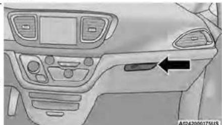
natural_image
Interior view of a car dashboard with control panels and a directional arrow pointing to the left side (no text or symbols present)ReleaseHandle
FrontDoorStorage
Both interior front door panels have multiple storage.
WARNING!
If containers of hot liquid are placed in t holder, they can spill when the door is cl the occupants. Be careful when closing the avoid injury.
OverheadSunglassStorage
At the front of the overhead console, a compartment is provided for the storage of one pair of sunglasses.
From the closed position, push the indentation to open the compartment.
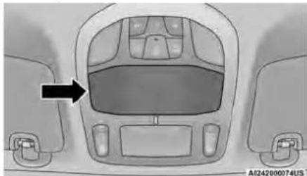
natural_image
Interior view of a car dashboard with steering wheel and side lockers (no text or symbols visible)OverheadSunglassDoorLatch
InstrumentPanelDrawer
pocketefois a storage drawer located in the lower the instrument panel. It can be released by pu access button above it. The drawer is actuator once the access button is pushed. Pull drawer to the fully open position.
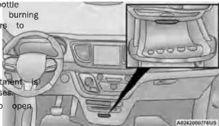
DrawerAccessButton
CAUTION!
The storage drawer must be closed while driving left open during a collision, additional damage occur to property or the drawer mechanism.
FrontSeatbackStorage—IfEquipped
The front seatbacks have a storage pocket on models.
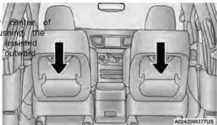
FrontSeatbackStorage
SecondRowFloorStorageBins
There are removable storage bins (if equipped) located in the areas below the load floor, located in front of second row seats.
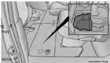
In-FloorStorageBin
The door will slowly rotate to the full open position.
- To access the storage bins with front seats rearward position, place the lock rod in the position so the load floor can fold upwards the seatback.
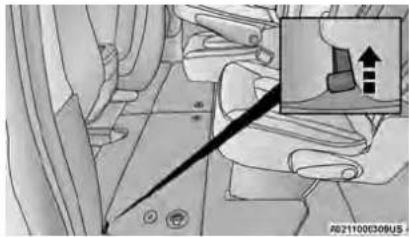
natural_image
Illustration of a hand pressing down on a car seatbelt, with an inset showing a hand holding a device (no text or symbols present)LockRod
NOTE:
○ Push the lock rod inward for the locked
○ Pull outward on the lock rod for the unlo position.
- Pull the latch located near the second row open the floor panel.
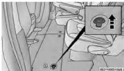
FloorLatch
| in the unlocked | WARNING! |
| towards | |
| in a collision, serious injury could result if storage bin covers are not properly latched. | |
| • Do not drive the vehicle with the storage open. | |
| • Keep the storage bin covers closed and while the vehicle is in motion. | |
| • Do not operate the storage bin covers w vehicle is in motion. | |
| • Do not use a storage bin latch as a t | |
the
| CAUTION! |
| The storage bin cover must lie flat and be avoid damage from contact with the front s which have minimal clearance to the cover. position |
| Age bin cover is left in the open position, chard adjustment may damage the cover. |
- In a collision, serious injury could result if the sea storage bin covers are not properly latched.
- does not drive the vehicle with the storage open. Keep the storage bin covers closed and latched while the vehicle is in motion.
- Do not operate the storage bin covers while the vehicle is in motion.
- Do not use a storage bin latch as a tie down.
own.
seat to
STORAGEBINSAFETYWARNING
Carefully follow these warnings to help prevent personal injury or damage to your vehicle:
WARNING!
- Always close the storage bin covers when your vehicle is unattended.
- Do not allow children to have access to the second row seat storage bins. Once in the storage bin, young children may not be able to escape. If trapped in the storage bin, children can die from suffocation or heat stroke.
(Continued)
WARNING!
| CAUTION! |
| The storage bin cover must lie flat and be avoid damage from contact with the front s which have minimal clearance to the cover. |
| Rise stop cover is left in the open position, adjustment may damage the cover. |
2
e latched seat tracks, If the st front sea
SEATSTORAGEBINCOVEREMERGENCY RELEASELEVER
As a security measure, the Seat Storage Bin (an Emergency Release Lever built into the latch mechanism.
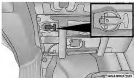
natural_image
Technical diagram of a mechanical component with a magnified inset showing a close-up detail (no text or symbols present)StorageBInCoverEmergencyReleaseLever
NOTE:
In the event of an individual being locked inside the storage bin, the storage bin cover can be opened inside of the bin by pushing on the glow-in-the-dark lever attached to the storage bin cover latching mechanism.
USB/AUX CONTROL
There are numerous USB ports located throughout the vehicle that allow an external USB device to be plugged into the USB port. There are four, fully functional USB ports: Two Mini-USBs (Type C) and two Standard USBs (Type A). There is also an AUX port located between the USB ports.
NOTE:
Two devices can be plugged in at the same vehicle and both ports will provide charging capabilities. Only on the back of the front row seats (if equipped). For then transfer data to the system at a time. Above the rear cup holder in the third row seats will appear and allow you to select the device transfer (if equipped).
For example, if a device is plugged into the Type A USB port and another device is plugged into the Type C USB port, a message will appear and allow you to select which device to use.
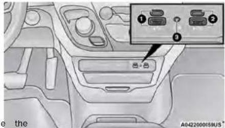
FrontCenterStackAUXJackAndUSBPorts
1 - Type C And Type A USB Ports 1 2 - Type C And Type A USB Ports 2 3 - AUXPort
There are multiple USB "Charge Only" ports in this vehicle and
● On the back of the front row seats (if equipped). ● A pop-up ● Above the rear cup holder in the third row seats (If equipped).
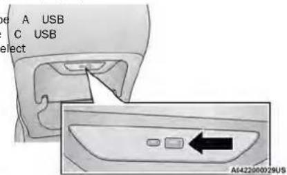
RearSeatUSBChargingPort
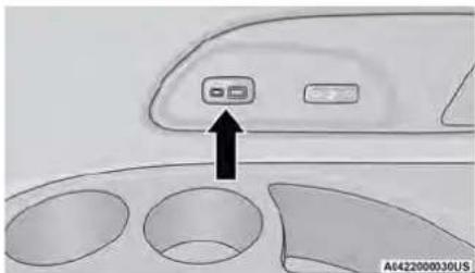
3rdRowUSBChargingPort—IfEquipped
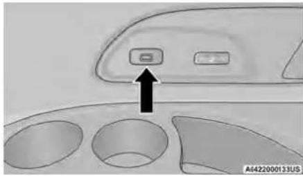
natural_image
Interior view of a vehicle dashboard with three circular compartments and a labeled control panel (no text or symbols on the main diagram)POWER OUTLETS
Your vehicle is equipped with 12 Volt (15 Amp) outlets that can be used to power cellular phones small electronics and other low powered electrical accessories. The power outlets can be labeled with either a "key" or a "battery" symbol to indicate the outlet is powered. Power outlets labeled with a key powered when the ignition is in the ON/RUN or position, while the outlets labeled with a battery connected directly to the battery and powered at times.
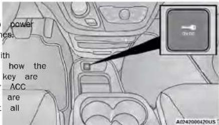
3rdRowUSBChargingPort—IfEquipped12VoltFrontPowerDilEst
NOTE:
The USB "Charge Only" ports will recharge battated USB devices when connected.
Different scenarios are provided when a non-pho device is plugged into the smaller and larger and when a phone device is plugged into the and larger USB ports:
- "A new device is now connected. Previous cotton was lost."
- “(Phone Name) now connected. Previous conned was lost.”
- "Another device is in use through the same port. Please disconnect the first device to use second device."
Plugging in a phone or another USB device may cause the connection to a previous device to be lost.
All accessories connected to the battery powered out-
lets should be removed or turned off when the vehicle is open-in use to protect the battery against discharge.
- Not in use to protect the battery against
| e | CAUTION! |
| SB ports. |
Shower outlets are designed for accessory plugs Do not insert any other object in the power this will damage the outlet and blow the fus Improper use of the power outlet can cause not covered by your New Vehicle Limited War tion
Your vehicle may be equipped with a front point of the bottom of the instrument panel, the storage tray.
The rear power outlet is located in the right rear ca area.
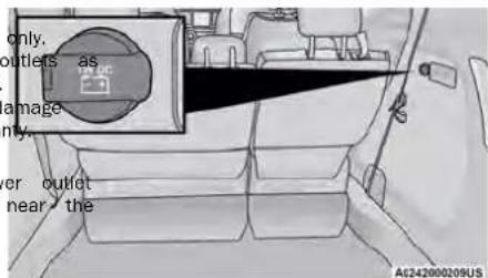
RearPowerOutlet
NOTE:
Charge unsupported devices with the Charge Only USB
ports. If an unsupported device is plugged into a Media
USB port, a message will display on the touchscreen
that the device is not supported by the system.
NOTE:
The front power outlet can be changed to batter ered at all times by switching the power outlet the Power Distribution Center panel from fuse loc F95A to F95B.
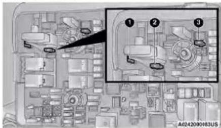
PowerOutletFuseLocations
1 - F95A (Ignition)/F95B (Battery) Front Power 10A (If Equipped)
2 - F85 Cigar Lighter 20A
3 - F60 RR Cargo Power Outlet 20A
WARNING!
To avoid serious injury or death:
- Only devices designed for use in this type should be inserted into any 12 Volt outlet.
- Do not touch with wet hands.
- Close the lid when not in use and while vehicle.
- If this outlet is mishandled, it may cause tric shock and failure.
of outlet
driving the
an elec-
Windows
POWER WINDOWS
The window switches on the driver's door trim control all of the door windows.
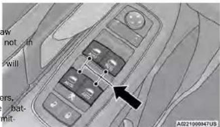
Driver's PowerWindowControls
The driver may lock out the rear power windows by pushing the bar control just below the power window controls.
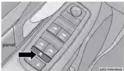
PowerWindowLockoutSwitch
The window switches will operate only when the ignition is in the ON/RUN or ACC position and during power accessory delay.
NOTE:
NOTE:
Power Window controls will also remain active foTheupsliding door windows do not fully open, stop
10 minutes after the ignition has been placed several inches above the window sill.
OFF position, depending upon the accessory delay set-
ting. Opening a front door will cancel this feature AUTOMATIC WINDOW FEATURES
There is a single control on the front passenger's door Auto-DownFeature
trim panel which operates the passenger door window. The driver and front passenger door power window
and a set of controls that lock and unlock all doors. The switcher, broke on Auto Down feature. Push the
controls will operate only when the ignition is in the switches have all Auto-Down feature. Push the
ON/RUN or ACC position and during power accessory switch past the first detent, release, and the
delay.
SlidingSideDoorPowerWindowControl—IfEquipped
Second row passengers may open and close the
door window by a single control on the door
assem
The controls will operate only when the ignition
is in the ON/RUN or ACC position and during
accessory delay.
NOTE:
The controls will not operate if the driver has
the Power Window Lockout.
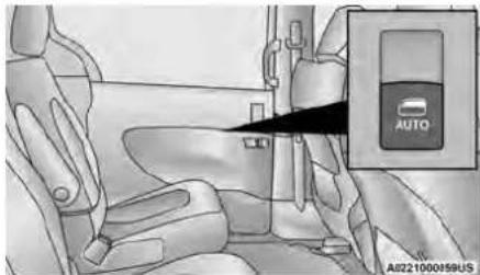
natural_image
Interior view of a car showing seatbelt and automatic door panel (no text or symbols)SlidingDoorPowerWindowControl(LeftSideShown)
To stop the window from going all the way of
the Auto-Down operation, pull up on the switch
Auto-UpFeatureWithAnti-PinchProtection
handle Lift the window switch fully upward to the sec
detent, release, and the window will go up
switch automatically.
power To stop the window from going all the way
to stop the window from going all the way to
Auto-Up operation, push down on the switch br
To close the window part way, lift the window
Invitated and release it when you want the wind
| opping | WARNING! |
| There is no anti-pinch protection when the v almost closed. To avoid personal injury be s clear your arms, hands, fingers and all obje the window path before closing. | |
2
RESET AUTO UP
To reactivate the Auto Up feature, perform the followin
steps after vehicle power is restored:
briefly, the window control up to close the window.
- Pull the window control up to close the window completely and continue to hold the control up for an
pletely and continue to hold the control up for a additional two seconds after the window is closed.
nd additional two seconds after the window is closed.
- Push the window control down firmly to the second
detent to open the window completely and continue
dtoingholthe the control down for an additional two sec
fly. onds after the window is fully open.
WIND _stop. BUFFETING
Wind buffeting can be described as the perception of
presdown. on the ears or a helicopter-type sound in th
eagainYour vehicle may exhibit wind buffeting with the
windows down, or the sunroof/Power Sliding Top
(if equipped) In certain open or partially open positions
This is a normal occurrence and can be minimized. If
rigger buffeting occurs with the rear windows open, open
ene front and rear windows together to minimize the
buffetingse If the buffeting occurs with the sunroof open
adjust the sunroof opening to minimize the buffeting o
open any window.
HOOD
OPENING
The hood release lever (to open the primary latch) safety latch (to open the secondary latch) must be released to open the hood.
- Pull the hood release lever located under the er's side of the instrument panel.
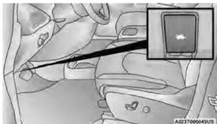
natural_image
Medical illustration showing a surgical instrument inserted into a car seat, with an inset close-up of the device (no text or symbols visible)HoodReleaseLever
-
Move to the outside of the front of the
-
Push the safety latch release lever toward senger side of the vehicle. The safety latch located behind the center front edge of the
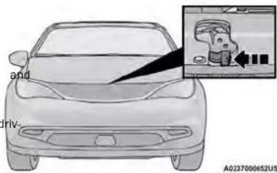
SafetyLatchReleaseLeverLocation
- Remove the support rod from the locking ta insert it into the seat located on the unders the hood.
NOTE:
- Before lifting the hood, check that the wiper arms are not in motion and not in the lifted position.
- While lifting the hood, use both hands.
- Vehicle must be at a stop and the transmis vehicle must be in PARK.
TO ^pas- CLOSE THE HOOD
hood. Hold up the hood with one hand and with hand remove the support rod from its seat sert it into the locking tab.
2. Lower the hood to approximately 12 inches from the engine compartment and drop it. M sure that the hood is completely closed.
WARNING!
Be sure the hood is fully latched before driving your vehicle. If the hood is not fully latched, it could open when the vehicle is in motion and block your vision. Failure to follow this warning could result in serious injury or death.
CAUTION!
To prevent possible damage, do not slam the hood to close it. Lower hood to approximately 12 inches (30 cm) and drop the hood to close. Make sure hood fully and closed for both latches. Never drive vehicle unless hood is fully closed, with both latches engaged.
LIFTGATE
TO UNLOCK/OPEN THE LIFTGATE
The liftgate may be released in several ways:
• Key fob
- Outside handle
- Button on overhead console
Push the liftgate button on the key fob twice within seconds to release the liftgate.
The key fob and the overhead console button will release the liftgate when the liftgate is locked. The on side handle requires the liftgate to be unlocked. If the vehicle is equipped with Passive Entry, pulling the outside handle will unlock and release the liftgate, with . valid Passive Entry key fob within 5 ft (1.5 m) of the liftgate.
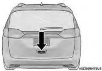
natural_image
Front view of a car with a black arrow pointing to the side panel (no text or symbols)ElectronicLiftgateReleaseHandle
POWER LIFTGATE — IF EQUIPPED
The power liftgate may be opened or closed in ways:
• Overhead console liftgate button
• Key fob
- Outside handle (open or reset liftgate latch)
- Rear interior power liftgate switch on the
trim (when liftgate is open)
Using the previous ways to open or close the
- When the liftgate is fully closed, the liftgate
- When the liftgate is fully open, the liftgate
- When the liftgate is moving, the liftgate will
The key job and the overhead console button will operate the liftgate when the liftgate is locked. The outside
handle requires the liftgate to be unlocked. If the vehicle is equipped with Passive Entry, pressing the touch pad on the outside handle will unlock and open the liftgate, with a valid Passive Entry key for (1.5 m) of the liftgate handle.
NOTE!
Tones are sounded and the turn signals are flashed with liftgate movements. These alerts can be turned or
v8k open in Uconnect Settingage 100.
vtbCloseTheLiftgate
The liftgate can also be closed using the Rear Interior Power Liftgate button (if equipped), located in the upper left trim in the liftgate opening.
W
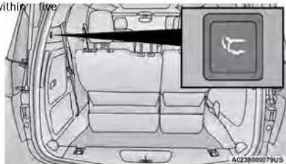
RearInteriorPowerLiftgateSwitch
WARNING!
- Driving with the liftgate open can allow exhaust gases into your vehicle. You and sengers could be injured by these fumes. liftgate closed when you are operating the
- If you are required to drive with the lift make sure that all windows are closed, climate control blower switch is set at h Do not use the recirculation mode.

OverheadConsolePowerSwitches
speed. Liftgate
2 - Left Sliding Door
3 - Sliding Door Power Off
4 - Right Sliding Door
NOTE:
If the power liftgate will not fully open or la check the latch for damage or obstacles that preventing the closing operation. If the problem sists, proceed as follows:
- Press the electronic liftgate release handle on outside of the liftgate to home/reset the latch mechanism.
- Manually close the liftgate by pulling downward using the closing handle.
- Resume normal power liftgate open or closing operation.
If the home/reset procedure is unsuccessful, see authorized dealer for service.
CARGO AREA FEATURES
may cargoAreaStorage
When the third row seats are not in the stowed position, there is a large area for cargo storage.
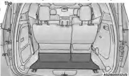
natural_image
Top-down line drawing of a car interior showing rear seats and dashboard (no text or symbols)RearCargoArea
NOTE:
With all rear seats stowed or removed, 4 x 8 ft (1.2 x 2.4 m) sheets of building material will fit on the vehicle floor with the liftgate closed. The front seats must be moved slightly forward of the rearmost position.
GETTINGTOKNOWYOURINSTRUMENTPANEL
BASEINSTRUMENTCLUSTER
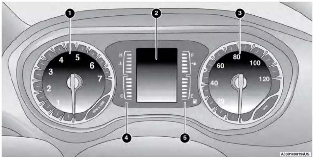
UsethisQRcodetoaccessyourdigital experience.
WARNING!
A hot engine cooling system is dangerous. You or others could be badly burned by steam or boiling coolant. You may want to call an authorized dealer for service if your vehicle overhead page 186.
BASE INSTRUMENT CLUSTER DESCRIPTIONS
- Tachometer
○ Indicates the engine speed in revolutions minute (RPM x 1000).
- Instrument Cluster Display
When the appropriate conditions exist, this play shows the instrument cluster display sages page 60.
- Speedometer
○ Indicates vehicle speed.
- Temperature Gauge
The temperature gauge shows engine coolant temperature. Any reading within the normal range indicates that the engine cooling system is operating satisfactorily.
The gauge can indicate a higher temperature when driving in hot weather or up mountain grades. It should not be allowed to exceed the upper limits of the normal operating range.
CAUTION!
Driving with a hot engine cooling system could damage your vehicle. If the temperature gauge reaches "H" pull over and stop the vehicle. Idle the vehicle with the air conditioner turned off until the gauge drops back into the normal range and is no longer red. If the gauge remains on the "H", turn the engine off immediately and call an authorized dealer for dis service.
- Fuel Gauge
☐ The gauge shows the level of fuel in the fuel tank when the ignition switch is in the ON/RUN position.
○ The fuel pump symbol points side of the vehicle where the door is located.

PREMIUMINSTRUMENTCLUSTER
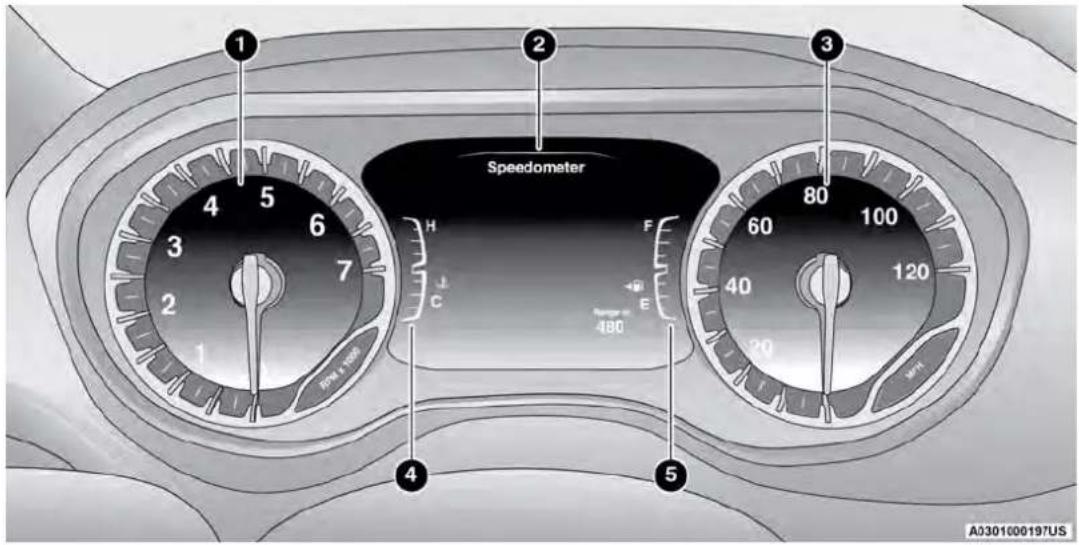
PREMIUM INSTRUMENT CLUSTER DESCRIPTIONS
- Tachometer
○ Indicates the engine speed in revolutions minute (RPM x 1000).
- Instrument Cluster Display
When the appropriate conditions exist, this play shows the instrument cluster display sages → page 60.
- Speedometer
○ Indicates vehicle speed.
- Temperature Gauge
The temperature gauge shows engine coolant temperature. Any reading within the normal range indicates that the engine cooling system is operating satisfactorily.
The gauge can indicate a higher temperature when driving in hot weather or up mountain grades. It should not be allowed to exceed upper limits of the normal operating range.
CAUTION!
Driving with a hot engine cooling system could age your vehicle. If the temperature gauge is "H" pull over and stop the vehicle. Idle the with the air conditioner turned off until the drops back into the normal range and is no red. If the gauge remains on the "H", turn off immediately and call an authorized dealer service.
trols allow you to scroll through and enter the main menus and submenus. You can access the specific information you want and make selections and adjustments.
INSTRUMENT CLUSTER DISPLAY LDER LOCATION AND CONTROLS
the engine The vehicle's instrument cluster is equipped with an instrument cluster display (base or premium cluster), which offers useful information to the driver.
- Fuel Gauge
The gauge shows the level of fuel in the fuel tank when the ignition switch is in the ON/RUN position.
○ The fuel pump symbol points side of the vehicle where the door is located.

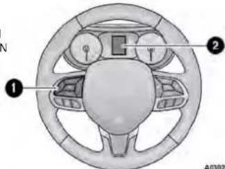
A0302000168US
INSTRUMENTCLUSTERDISPLAY
Your vehicle is equipped with an instrument cluster dis- InstrumentClusterDisplayLocation
| WARNING! |
| A hot engine cooling system is dangerous.ers could be badly burned by steam or bant. You may want to call an authorized cservice if your vehicle overpage 186. |
play, which offers useful information to the driver. With
the ignition in the OFF position (and the key remove instrument Cluster Display Controls
for vehicles with mechanical key), opening/closing 2of - a Instrument Cluster Display Screen
door will activate the display for viewing, and display the
total miles or kilometers in the odometer. Your structure for the instrument cluster display controls allows the driver of a target cluster display is designed to display important to select information by pushing the directional buttons information about your vehicle's systems and features. Meated on the steering wheel:
Using a driver interactive display located on the instru-
ment panel, your instrument cluster display can show
you how systems are working and give you warnings
when they are not. The steering wheel mounted con-
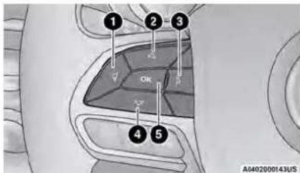
InstrumentClusterDisplayControls
1 - Left Arrow Button
2 - Up Arrow Button
3 - Right Arrow Button
4 - Down Arrow Button
5 - OK Button
- Back/LeftArrowButton
Push and release the leftow button to access the information screens or submenu screens of main menu item.
- UpArrowButton
Push and release the arrow button to scroll upward through the Main Menu items.
- RightArrowButton
Push and release the rightow button to access the information screens or submenu of a main menu item.
- DownArrowButton
Push and release the downow button to scroll downward through the Main Menu items.
- OKButton
Push the OKbutton to access/select the informa. Without pressing the brake pedal, push the ENGINE tion screens or submenu screens of a Main MeStart/STOP button and place the ignition in the item. Push and hold the OKbutton for two seconds OKRUN position (do not start the vehicle.)
to reset displayed/selected features that can be reset. 2. Push the OKbutton to enter the instrument cluster display menu screen.
OIL LIFE RESET
UsethisQRcodetoaccessyourdigital experience.
- Your vehicle is equipped with engine oil change indicator sys The "Oil Change Required" me will display for approximately 1 seconds after a single chime
sounded, to indicate it is time to change the SecondaryMethodForOilLifeResetProcedure oil. The engine oil change indicator system is duty cycle based, which means the engine oil change in the ON/RUN position (do not start the engine). interval may fluctuate dependent upon your per
sonal driving style. 2. Fully press the accelerator pedal, slowly, three times Unless reset, this message will continue to display within 10 seconds.
each time the ignition is cycled to the ON/RGN. Without pushing the brake pedal, place the ignition position. In the OFF position.
To reset the oil change indicator after performing the scheduled maintenance, refer to the following procedure. NOTE: If the
NOTE:
This procedure should only be performed after scheduled maintenance is completed. Resetting oil life other than when associated with a scheduled maintenance may result in damage due to not properly maintaining the engine oil.
If the indicator message illuminates when you start the vehicle, the oil change indicator system did not reset. necessary, repeat this procedure.
3
INSTRUMENT CLUSTER DISPLAY MENU ITEMS
The instrument cluster display can be used to main menu items for several features. Use the △ and downarrow buttons to scroll through the driver interactive display menu options until the menu is reached page 60.
NOTE:
The instrument cluster display menu items display the center of the instrument cluster. Menu items vary depending on your vehicle features.
Speedometer
Push and release the upor downarrow button until Speedometer is highlighted in the instrument ter display. Push and release the OKbutton to t between MPH and km/h.
VehicleInfo
Push and release the upor downarrow button until Vehicle Info is highlighted in the instrument display. Push the left rightarrow button to scroll through the following information submenus:
TirePressure
If tire pressure is OK for all tires, a vehicle icon played with tire pressure values in each corner icon.
If one or more tires have low pressure, "Inflate XX" is displayed with the vehicle icon, and the
sure values in each corner of the icon with the value of the low tire displayed in a different of the other tire pressure value.
If the Tire Pressure system requires service, "Ser Tire Pressure System" is displayed.
Tire PSI is an information only function and reset → page 127.
CoolantTemp
view the displays the actual coolant temperature.
TransmissionTemp
Displays the actual transmission temperature.
OilTemp
Displays the actual oil temperature.
OilPressure
Displays the actual oil pressure.
OilLife
Displays the remaining engine oil life as a percentage particular engine requirements
To reset the Oil Life, you must hold the OKbuttonHoldThe OKto reset average fuel economy information.
"Hold OK to Reset" instruction will be displayed at all
times, but the following conditions will need to triplnfe ogle in order to reset Oil Life:
- The ignition must be in the ON/RUN position, push and release the up/down arrow button until the Trip Menu item is highlighted in the instrument. If the conditions are met, holding the OK button clicker display. Push the left right arrow but reset the gauge and the numeric display will return to scroll through the Trip A and Trip B submenu 100%. The Trip information will display the following:
If the conditions are not met, a pop-up message Distance
display for five seconds, describing the required condi- Average Fuel Economy
tions, and then the Oil Life screen will reappear.
BatteryVoltage
Displays the actual battery voltage.
EngineHours—IfEquipped
Displays to the number of hours of engine ope
tire pres- DriverAssist—IfEquipped until the ment cl
por than push and release the upor downarrow button
until the Driver Assist display icon is highlighted in the
FuelEconomy
Push and release the upor downarrow button until the Fuel Economy Menu item is highlighted in the instrument cluster display. The Fuel Economy Menu will display the following:
- Two submenu pages that can be toggled between using the left and rightarrow buttons; one with Current Value displayed and one without the Current Value displayed:
○ Average Fuel Economy (MPG, L/100 km, or km,
○ Range To Empty (miles or km)
○ Current Fuel Economy (MPG, L/100 km, or km/
The Max and Min values will correspond to th
centage particular engine requirements
uttonHoldTheOKto reset average fuel economy information.
at all
Triplinfo
Push and release the up downarrow button
until the Trip Menu item is highlighted in the instrum
cluster display. Push the left rightarrow but-
eturn to scroll through the Trip A and Trip B submenu
The Trip information will display the following:
ge Dwiller
condi Average Fuel Economy
- Average Pass of.
- Elapsed Time
Hold the OKbutton to reset feature information.
Stop/Start-IfEquipped
push and release the upor downarrow button until the Stop/Start menu title is displayed in the inst ment cluster display.
[Non-Text]
in the
[Non-Text]
Audio
Push and release the upor downarrow button until the Audio Menu displays in the instrument display.
Messages
Push and release the upor downarrow button until Messages is highlighted in the instrument of display. This feature shows the number of stored warning messages. Pushing the rightow button will allow you to see what the stored messages
NOTE:
The pop-up messages indicate the status of the and/or the conditions that need to be met. Me remain in the stored stack until condition is close
ScreenSetup
Push and release the upor downarrow button until the Screen Setup Menu displays in the ins cluster display. Push and release the OKbutton to the submenus. The Screen Setup feature allows change what information is displayed in the inst cluster as well as the location that information displayed.
BASEINSTRUMENTCLUSTERDISPLAY SCREENSETUOPTIONS
Push and release the upon downarrow button until the Screen Setup Menu displays in the instrument cluster display. Push and release the OKbutton to enter the submenus. The Screen Setup feature allows you to change what information is displayed in the instrument cluster as well as the location that information is displayed.
| UpperLeftorUpperRight | ||
| None Compass cluster | (If Equipped) | Outside Temp |
| Average (MPG, L/100km, or km/L) | Time Range | |
| Current (MPG, L/100km, or km/L) | ||
| Center | ||
| None Compass system ssages | (If Equipped) | Outside Temp |
| Average (MPG, L/100km, or km/L) | Range Time | |
| Current (MPG, L/100km, or enter/L) | Trip A Distance Trip B Dista | |
| Audio to Menu T ument | Title Digital Speed | |
| LowerLeftorLowerRight | ||
| None Compass | (If Equipped) | Outside Temp |
| Time Range to | Empty Average | (MPG, L/100km, or km/L) |
| Trip A Distance | Trip B Distance | Current (M L/100km, or km/L) |
| UpperCenter | ||
| None Compass | (If Equipped) | Outside Temp |
| Time Range to | Empty Average | (MPG, L/100km, or km/L) |
| Trip A Distance | Trip B Distance | Current (M L/100km, or km/L) |
| Audio/Phone | Digital Speed | Menu Title |
Odometer
• Show
- Hide
Defaults
- Restore
- Cancel
BATTERY SAVER ON/BATTERY SAVER MODE MESSAGE — ELECTRICAL LOAD REDUCTION ACTIONS — IF EQUIPPED
This vehicle is equipped with an Intelligent Batter sor (IBS) to perform additional monitoring of the cal system and status of the vehicle battery.
In cases when the IBS detects charging system or the 12 Volt vehicle battery conditions are d ing, electrical load reduction actions will take p
extend the driving time and distance of the ve is done by reducing power to or turning off re essential 12 Volt electrical loads. Load reduction functional when the vehicle propulsion system is
The vehicle may not be running depending on Voltage (HV) battery State Of Charge (SOC) or ture. It will display a message if there is a depletion to the point where the vehicle may to lack of electrical supply, or will not restart current drive cycle.
When 12 Volt load reduction is activated, the "Battery Saver On" or "Battery Saver Mode" will in the instrument cluster display.
These messages indicate the vehicle battery has state of charge and continues to lose electrical at a rate that the charging system cannot sus
NOTE:
- The charging system is independent from load reduction. The charging system performs a diptic on the charging system continuously.
- If the Battery Charge Warning Light is on it may cate a problem with the charging system 65
- The battery was recently replaced and was not charged completely.
- The battery was discharged by an electrical load left on when the vehicle was parked.
[Non-Text]
load left
[Non-Text]
The following are electrical loads that may be off (if equipped), and vehicle functions which affected by load reduction:
- Heated Seat/Vented Seats/Heated Wheel
- Heated/Cooled Cup Holders — If Equipped
- Rear Defroster And Heated Mirrors y Sen- - HVAC System
• 115 Volts AC Power Inverter System
failAudio and Telematics System
teriorat Loss of the battery charge may indicate one to the following conditions:
The charging system cannot deliver enough power to the vehicle system because loads are larger than the capability of
the system. The charging system is still function he properly.
- Turning on all possible vehicle electrical load of battery HVAC to max settings, exterior and interior
an overloaded power outlets +12 Volts, 150W, after the ports) during certain driving conditions (city towing, frequent stopping).
- installing options like additional lights, upfitter - appear - trical accessories, audio systems, alarms and - lar devices.
a low charge. Unusual driving cycles (short trips separated by long parking periods).
- The vehicle was parked for an extended period of time (weeks, months).
iod of
not
switched battery was used for an extended period with the engine not running to supply radio, lights, chargers, +12 Volt portable appliances like vacuum cleaners, game consoles and similar devices.
Whattodowhenanelectricalloadreductionaction messageispresent("BatterySaverOn" or "Battery SaverMode")
During a trip:
- Reduce power to unnecessary loads if possible:
○ Turn off redundant lights (Interior or exterior)
• More Check what may be plugged in to power outlet
+12 Volts, 150W, USB ports
Electri ^O Check HVAC settings (blower, temperature) electri ^O Check the audio settings (volume)
cAfteginga trip:
Check if any aftermarket equipment was installed (additional lights, upfitter electrical accessories, (egdio systems, alarms) and review specifications lightsany (load and Ignition Off Draw currents).
SB Evaluate the latest driving cycles (distance, driving driving time and parking time). - The vehicle should have service performed if the message is still present during consecutive trips and the evaluation of the vehicle and driving patter did not help to identify the cause.
by long
[Non-Text]
[Non-Text]
[Non-Text]
WARNINGLIGHTSANDMESSAGES
The warning/indicator lights will illuminate in the ment panel together with a dedicated message acoustic signal when applicable. These indications indicative and precautionary and as such must considered as exhaustive and/or alternative to the Information contained in the Owner's Manual, wh
you are advised to read carefully in all cases. reservoir. Always
refer to the information in this chapter in the level of right remains on when the parking brake
failure Indication All active warning/indicator lights been disengaged. and the fluid level is at the Distribution (EBD). In the event of an EBD fa
dienlau firet if applicable The custom check manan ribe master cylinder reservoir it indicates a Breaker Warning Light will turn on along with the ABS
display first if applicable. The system check inside may monitor system recovery, it indicates a problem. Immediate repair to the ABS system is required.
current vehicle status Some warning/indicator light with the Brake Booster has been detected by the Action of the Brake Warning Light can be checked
current vehicle status, some running indicator ignition, the brand vessel has even access by population of the Brand running light can be exceeded are optional and may not appear. Lock Brake System (ABS) / Electronic Stability Controlturning the ignition switch from the OFF position to
are optional and may not appear. Even, the system (FSC) is currently existing, every uniting the ignition amplit from the ON position (FSC) system. In this case, the light will remain than _100 in position. The light should illuminate for
RED WARNING LIGHTS
related to the brake booster. the ABS numb will effume place the Norway brake is applied or a brake f
AirBagWarningLight

This warning light will illuminate to indicate he felt during each stop. light inspected by an authorized dealer.
fault with the air bag, and will turn of the foual brake system provides a reserve braking the light also will turn on when the parking brake is
four to eight seconds as a bulb checkcademy in the event of a failure to a portion applied with the ignition switch in the ON/RUN position
the ignition is placed in the ON/RUN Mydotic system. A leak in either half of the dual brake
ON/RUN position. This light will illuminate with asysingle is indicated by the Brake Warning Light, NOTE
chime when a fault with the air bag has been wildetected on when the brake fluid level in the Thirastight shows only that the parking brake is applied
it will stay on until the fault is cleared. If the cylinder has dropped below a specified level. It does not show the degree of brake application.
either not on during startup, stays on, or turns on while the light will remain on until the cause is corrected.
driving, have the system inspected at an authorized DoorOpenWarningLight—ItEquipped
dealer as soon as possible.
BatteryChargeWarningLight

This warning light will illuminate when the vehicle should have service performed and the H is in our will reflect which doors are open.
battery is not charging properly. If it stays on all checked
while the engine is running. there may be a
malfunction with the charging system. If brake failure is indicated, immediate repair is NOTE:
tact an authorized dealer as soon as possible, necessary.
This indicates a possible problem with the electrical
system or a related component.
BrakeWarningLight

This warning light monitors various brake
functions, including brake fluid level and
parking brake application. If the brake
turns on it may indicate that the parki
tams on it may indicate that the parking applied that the brake fluid level is
applied, that the brake fluid level is in a problem with the Antilock Brake.
a problem with the Anti-Lock Brake Sys
reservoir. Always
If the right remains on when the parking brake
beem disengaged, and the fluid level is at the
on the master cylinder reservoir it indicates a
broke hydraulic system malfunction or that a prol
make hydraulic system malfunction of that a prof with the Brake Rooster has been detected by th
with the Brake Booster has been detected by a Look Brake System (ABS) / Electronic Stability Co
Lock Brake System (ABS) / Electronic Stability Co (500) system In this case, the light will remain
(ESC) system. In this case, the light will remain:
the condition has been corrected. If the problem
related to the brake booster, the ABS pump will
when applying the brake, and a brake pedal pu
they be felt during each stop.
The forual brake system provides a reserve braking
When in the event of a failure to a portion
capacity in the event of a failure to a portion
hydraulic system. A leak in either half of the d
systeme is indicated by the Brake Warning Light,
will detected on when the brake fluid level in the
eylligher has dropped below a specified level.
Then while will remain on until the cause is corr
The light will remain on until the cause is confined
NOTE:
The light may flash momentarily during sharp con
the light may hash momentarily during sharp operations maneuvers which change fluid level conditions. Th
the vehicle should have service performed and the h
tavs. on
fluid level checked.
If brake failure is indicated, immediate repair is
on- necessary.

Driving a vehicle with the red brake light on is dan
Notes. Part of the brake system may have failed. It w
intake longer to stop the vehicle. You could have a c
gains longer to stop the vehicle. You should have a estion or Haven the vehicle checked immediately
OWNS OF HANAT the Vehicle checked immediately.
Vehicles equipped with the Anti-Lock Brake System
(ABS) are also equipped with Electronic Brake
Distribution (EBD). In the event of an EBD fa
Breaktle Warning Light will turn on along with the ABS
light. Immediate repair to the ABS system is required.
The Action of the Brake Warning Light can be checked
Operation of the Brake Warning Light can be checked Introducing the ignition switch from the OFF position.
by-claiming the ignition switch from the off-position & then CONTRUN position. The light should illuminate for
the "DAYTON" position. The light should illuminate for approximately two seconds. The light should then turn
approximately two seconds. The light should then turn off from the parking brake is applied or a brake f
on—unless the parking brake is applied for a brake kit isolation-rected. If the light does not illuminate have the
is- detected. If the light does not laminate, have the light inspected by an authorized dealer.
The light also will turn on when the parking broke is
the light also will turn on when the parking brake is
applicable with the ignition switch in the ON/RUN position
dual brake NOTE:
which
Timistnight shows only that the parking brake is applied
It does not show the degree of brake application.
rected
DoorOpenWarningLight—IfEquipped
This warning light will illuminate when a door.
This warning light will illuminate when a door
is ajar/open and hot fully closed. This indica-
tor will reflect which doors are open.
NOTE:
If the vehicle is moving, there will also be a single
chime.
ElectricPowerSteering(EPS)Fault WarningLight

This warning light will turn on when fault with the EPS system page 81.
WARNING!
Continued operation with reduced assist could safety risk to yourself and others. Service is obtained as soon as possible.
ElectronicThrottleControl(ETC)Warning Light

This warning light will illuminate to problem with the ETC system. If a
detected while the vehicle is running, light will either stay on or flash de
the nature of the problem. Cycle the ignition vehicle is safely and completely stopped and mission is placed in the PARK (P) position. should turn off. If the light remains on with running, your vehicle will usually be drivable; see an authorized dealer for service as soon possible.
NOTE:
This light may turn on if the accelerator and als are pressed at the same time.
If the light continues to flash when the vehicle ning, immediate service is required and you may ence reduced performance, an elevated/rough idle of greena stall and your vehicle may require towing light will come on when the ignition is placed ON/RUN or ACC/ON/RUN position and remain on as a bulb check. If the light does not come starting, have the system checked by an author dealer.
EngineCoolantTemperatureWarning Light

This warning light warns of an overhead engine condition. If the engine coolant perature is too high, this indicator will nate and a single chime will sound.
temperature reaches the upper limit, a continuous
ndicate time will sound for four minutes or until the probable to cool; whichever comes first.
the light turns on while driving, safely pull pending the vehicle. If the Air Conditioning (A/C)
when, then it off. Also, shift the transmission into the (N)ran and idle the vehicle. If the temperature rea The dust not return to normal, turn the engine off that vehicleed call for servipage 179.
sHoodOpenWarningLight

This warning light will illuminate when the hood is left open and not fully closed.
NOTE:
If the vehicle is moving, there will also be a single chime.
LiftgateOpenWarningLight
This warning light will illuminate when the liftgate is open.
NOTE: during
If the vehicle is moving, there will also be a single chime.
OilTemperatureWarningLight
This warning light will illuminate to indicate the engine oil temperature is high. If the light turns on while driving, stop the vehicle and shut off the engine as soon as possible. Wa fothe oil temperature to return to normal levels.
OilPressureWarningLight
This warning light will illuminate to indicate low engine oil pressure. If the light turns on while driving, stop the vehicle, shut off the engine as soon as possible, and contact an authorized dealer. A chime will sound when this light turns in.
Do not operate the vehicle until the cause is correct. This light does not indicate how much oil is in the engine. The engine oil level must be checked under t
theod.
SeatBeltReminderWarningLight

This warning light indicates when the driver or passenger seat belt is unbuckled. With the ignition is first placed in the ON/RACC/ON/RUN position and if the driver's bit is unbuckled, a chime will sound and on. When driving, if the driver or front belt remains unbuckled, the Seat Belt Light will flash or remain on continuous will soundpage 129.
seat belt will turn ger seat Reminder a chime
TransmissionTemperatureWarning Light

This warning light will illuminate to warn high transmission fluid temperature. This may occur with strenuous usage such a trailer towing. If this light turns on, stop and run the engine at idle or slightly transmission in PARK (P) or NEUTRAL (N), turns off. Once the light turns off, you must drive normally.
WARNING!
If you continue operating the vehicle when mission Temperature Warning Light is illumina could cause the fluid to boil over, come in with hot engine or exhaust components and fire.
CAUTION!
Continuous driving with the Transmission Temperature Warning Light illuminated will eventually cause severe transmission damage or transmission failure.
VehicleSecurityWarningLight—IfEquipped
This warning light will flash at a fast approximately 15 seconds when the vehicle security system is arming, and then will slowly until the vehicle is disarmed.
YELLOW WARNING LIGHTS
Anti-LockBrakeSystem(ABS)Warning Light
This warning light monitors the ABS. The light will turn on when the ignition is in the ON/RUN or ACC/ON/RUN position may stay on for as long as four sec
stop the ABS light remains on or turns on while faner, the with Anti-Lock portion of the brake system conditioning and service is required as soon as however, the conventional brake system will continue normally, assuming the Brake Warning Li not also on.
If the ABS light does not turn on when the placed in the ON/RUN or ACC/ON/RUN position,
the trans- d you the brake system inspected by an authorized de contact ElectricParkBrakeWarningLight

This warning light will illuminate to indicate the Electric Park Brake is not functioning properly and service is required. Contact authorized dealer.
ElectronicStabilityControl(ESC)Active WarningLight—IfEquipped
This warning light will indicate when the ESC system is Active. The ESC Indicator Light in the instrument cluster will come on when the ignition is placed in the ON/RUN or ACC/ON/
RUN position, and when ESC is activated. It should go out with the engine running. If the ESC India comes on continuously with the engine running function has been detected in the ESC system warning light remains on after several ignition cycles, and the vehicle has been driven several miles (kilometers) at speeds greater than 30 mph (48 km/h), see personalized dealer as soon as possible to have the problem and diagnosed and corrected.
The ESC OFF Indicator Light and the ESC Indicator light come on momentarily each time the ignition is placed in the ON/RUN or ACC/ON/RUN position. The ESC system will make buzzing or clicking sounds when it is active. This is normal; the sound will stop when ESC becomes inactive.
- This light will come on when the vehicle is in an ignition event.
ElectronicStabilityControl(ESC)OFF WarningLight—IfEquipped

This warning light indicates the ESC is off. Each time the ignition is turned to ON/RUN or ACC/ON/RUN, the ESC system will be on, even if it was turned off previously.
EngineCheck/MalfunctionIndicator WarningLight(MIL)

The Engine Check/Malfunction Indicator Light (MIL) is a part of an Onboard D tic System called OBD II that monitors engine and automatic transmission control
systems. This warning light will illuminate when t tion is in the ON/RUN position before engine st the bulb does not come on when turning the switch from OFF to ON/RUN, have the condition checked promptly.
Certain conditions, such as a loose or missing g poor quality fuel, etc., may illuminate the light a engine start. The vehicle should be serviced if t stays on through several typical driving styles. In situations, the vehicle will drive normally and will require towing.
When the engine is running, the MIL may flash serious conditions that could lead to immediate power or severe catalytic converter damage. The vehicle should be serviced by an authorized deal soon as possible if this occurs.
WARNING!
A malfunctioning catalytic converter can reach high temperatures than in normal operating conditions. This can cause a fire if you drive slowly or flammable substances such as dry plants, wood, cardboard, etc. This could result in death or se injury to the driver, occupants or others.
CAUTION!
Prolonged driving with the Malfunction Indicator (MIL) on could cause damage to the vehicle system. It also could affect fuel economy and ability. If the MIL is flashing, severe catalytic damage and power loss will soon occur. Immediate service is required.
ignition
FuelLevelSensorFailureWarningLight

This light illuminates when there is a level sensor failure. If this light illuminates take it to an authorized dealer and have them inspect it.
most
LowFuelWarningLight

When the fuel level reaches approximate 1.85 gal (7 L) this warning light will and remain on until fuel is added. A single warning chime will sound with
Fuel Warning.
LowWasherFluidWarningLight—IfEquipped

This warning light will illuminate when windshield washer fluid is low.
ServiceAutomaticEmergencyBraking (AEB)orPedestrianEmergencyBraking (PEB)WarningLight—IfEquipped

This warning light will illuminate to indicate a fault in the AEB Warning System. Contact an authorized dealer for service page 125.
ServiceStop/StartSystemWarning Light—IfEquipped

This warning light will illuminate when the Stop/Start system is not functioning properly and service is required. Contact an authorized dealer for service page 81.
TirePressureMonitoringSystem(TPMS) WarningLight

The warning light switches on and a message is displayed to indicate that the tire pressure is lower than the recommended value and/or that slow pressure loss is in these cases, optimal tire duration and fuel on may not be guaranteed.
Should one or more tires be in the condition previous mentioned, the display will show the indications corresponding to each tire.
CAUTION!
Do not continue driving with one or more handling may be compromised. Stop the vehicle avoiding sharp braking and steering. If a tire occurs, repair immediately using the dedicated repair kit and contact an authorized dealer as possible.
Your vehicle has also been equipped with a TP function indicator to indicate when the system is
flat operating properly. The TPMS malfunction indicator combined with the low tire pressure light. When
e puncture e system detects a malfunction, the light will flash approximately one minute and then remain contin
as soon illuminated. This sequence will continue upon subsequent vehicle start-ups as long as the maltion exists. When the malfunction indicator is illuminated, the system may not be able to detect
low be fire pressure as intended. TPMS malfunctions inflation occur for a variety of reasons, including the ins
of on replacement or alternate tires or wheels on
vehicle that prevent the TPMS from functioning p
eny. Always check the TPMS malfunction light at pres
replacing one or more tires or wheels on your
ensure that the replacement or alternate tires and wheels allow the TPMS to continue to function
een
YELLOW INDICATOR LIGHTS not
is AutomaticEmergencyBraking(AEB)or the PedestrianEmergencyBraking(PEB)
OFFIndicatorLight—IfEquipped
This indicator light illuminates to indicate that Forward Collision Warning is off.

3
GREEN INDICATOR LIGHTS
LTHS
CruiseControlSetIndicatorLight—IfEquipped

This indicator light will illuminate when the cruise control is set to the desired speed page 83.
FrontFogIndicatorLight—IfEquipped

This indicator light will illuminate when the front fog lights are on.
Parking/HeadlightsOnIndicatorLight

This indicator light will illuminate when the parking lights or headlights are turned on.
Stop/StartActiveIndicatorLight—IfEquipped

This indicator light will illuminate when the Stop/Start function is in "Autostop" mode page 81.
TurnSignalIndicatorLights

When the left or right turn signal is a the turn signal indicator will flash independently and the corresponding exterior turn signal lamps will flash. Turn signals can when the multifunction lever is moved up (right).
NOTE:
- A continuous chime will sound if the vehicle driven more than 1 mile (1.6 km) with either signal on.
- Check for an inoperative outside light bulb if indicator flashes at a rapid rate.
WHITE INDICATOR LIGHTS
CruiseControlReadyIndicatorLight
This indicator light will illuminate when cruise control is ready, but not set page 83.
SetSpeedDisplayIndicatorLight
The Set Speed Display indicator light cates the set speed for the Cruise

BLUE INDICATOR LIGHTS
HighBeamIndicatorLight
This indicator light will illuminate to indicate that the high beam headlights are on, the low beams activated, push the motion lever forward (toward the front of vehicle) to turn on the high beams. Pull the motion lever rearward (toward the rear of the vehicle) turn off the high beams. If the high beams are the lever toward you for a temporary high beam "flash to pass" scenario.
ONBOARDDIAGNOSTICSYSTEM—OBDII
Your vehicle is equipped with a sophisticated Onboard Diagnostic system called OBD II. This system monitors the performance of the emissions, engine, and automatic transmission control systems. When these systems are operating properly, your vehicle will provide excellent performance and fuel economy, as well as emissions well within current government regulations. If any of these systems require service, the OBD II system will turn on the Malfunction Indicator Light (MIL). Will also store diagnostic codes and other information to assist your service technician in making repairs. Although your vehicle will usually be drivable and not need towing, see an authorized dealer for service as soon as possible.
| CAUTION! |
| ●WifProlonged driving with the MIL on could of further damage to the emission control systethecould also affect fuel economy and driveat multiple vehicle must be serviced before any emissicle tests can be performed. |
| ●g pff.theMIL is flashing while the vehicle is severe catalytic converter damage and powwill soon occur. Immediate service is requi |
ONBOARD DIAGNOSTIC SYSTEM (OBD II) CYBERSECURITY
Your vehicle is required to have OBD II and port to allow access to information related to mance of your emissions controls. Authorized set technicians may need to access this information assist with the diagnosis and service of your 10 and emissions system page 100.
WARNING!
- ONLY an authorized service technician should not be equipment to the OBD II connection order to read the VIN, diagnose, or service vehicle.
- If unauthorized equipment is connected to OBD II connection port, such as a driver tracking device, it may:
○ Be possible that vehicle systems, incl safety related systems, could be impaired loss of vehicle control could occur that result in an accident involving serious death.
Access, or allow others to access, in stored in your vehicle systems, including sonal information.
EMISSIONSINSPECTIONAND MAINTENANCEPROGRAMS
a connection
the prefer-localities, it may be a legal requirement to review inspection of your vehicle's emissions control sys-

tem. Failure to pass could prevent vehicle registration.
For states that require an Inspection and Maintenance (I/M), this check verifies the
Malfunction Indicator Light (MIL) is functioning and is not on when the engine is running, and that the system is ready for testing.
port in ce your system may not be ready if your vehicle was recently serviced, recently had a depleted battery or a better replacement. If the OBD II system should be decent behavioral not ready for the I/M test, your vehicle vehicle the test.
Luding your vehicle has a simple ignition actuated test, while you can use prior to going to the test station. To may your vehicle's OBD II system is ready, you must be ready for following:
formationCycle the ignition switch to the ON position, but per- not crank or start the engine.
- Approximately 15 seconds later, one of two things will happen:
The MIL will flash for about 10 seconds and then return to being fully illuminated until you to pass OFF the ignition or start the engine. This means that your vehicle's OBD II system is not ready and you should not proceed to the I/M station.
○ The MIL will not flash at all and will 3 illuminated until you place the ignition i
is position or start the engine. This means that OBDI vehicle's OBD II system is ready and you can proceed to the I/M station.
If OBD I system is not ready, you should see an authorized dealer or repair facility. If your vehicle was normally serviced or had a battery failure or replacement, you may need to do nothing more than drive vehicles as you normally would in order for your OBD system to update. A recheck with the previously mentioned test routine may then indicate that the system now ready check if
Regardless of whether your vehicle's OBD II system is ready or not, if the MIL is illuminated during normal vehicle operation you should have your vehicle serviced before going to the I/M station. The I/M station can your vehicle because the MIL is on with the engine running.
NOTE:
If you crank or start the engine, you will have to start this test over.
- As soon as you cycle the ignition switch to the ON position, you will see the Malfunction Indicator Light (MIL) symbol come on as part of a normal bulb check.
Before starting your vehicle, adjust your seat, adj both inside and outside mirrors, and fasten your belts.
WARNING!
- When exiting the vehicle, always remove the fob from the vehicle and lock your vehicle.
- Never leave children alone in a vehicle, access to an unlocked vehicle.
- Allowing children to be in a vehicle unatter dangerous for a number of reasons. A childers could be seriously or fatally injured. Ch should be warned not to touch the parking brake pedal or the transmission gear selector
- Do not leave the key fob in or near the in a location accessible to children, and do leave the ignition of a vehicle equipped with less Enter 'n Go™ in the ACC or ON/RUN A child could operate power windows, other trols, or move the vehicle.
- Do not leave children or animals inside par vehicles in hot weather. Interior heat buildup cause serious injury or death.
NORMAL STARTING
ToTurnOnTheEngineUsingENGINESTART/STOP ust Button seat
- The transmission must be in PARK or NE
- Press and hold the brake pedal while pu ENGINE START/STOP button once.
key The system starts the vehicle. If the vehicle start, the starter will disengage automatically with 10 seconds. - If you wish to stop the cranking of the engine starting, push the button again.
ENGINESTART/STOPButtonFunctions—WithDriver's FootOffTheBrakePedal(InPARKOrNEUTRAL Position)
The ENGINE START/STOP button operates similar ignition switch. It has three positions; OFF, ACC, 00R/RUN. To change the ignition positions without key-the vehicle and to use the accessories, for operation.
-Start with the ignition in the OFF position. - Push the ENGINE START/STOP button once to be used the ignition to the ACC position (instrument may will display "ACC").
- Push the ENGINE START/STOP button a second to place the ignition to the ON/RUN position (NEUTRAL) cluster will display "ON/RUN").
- Push the ENGINE START/STOP button a third return the ignition to the OFF position (instru cluster will display "OFF").
NOTE:
Only press one pedal at a time while driving the vel Torque performance of the vehicle could be reduced if both pedals are pressed at the same time. If pressur Real detected on both pedals simultaneously, a warning message will display in the instrument cluster ing the page 60.
Autobark
After AutoPark is a supplemental feature to assist with placing the vehicle in PARK under certain situations. It is back-up pri-stem and should not be relied upon as the primary method by which the driver shifts the vehicle into PARK.
The conditions under which AutoPark will engage are outlined on the following pages.
to an
and
start-
ow These Inattention could lead to failure to place the vehicle in PARK. ALWAYS DO A VISUAL CHECK that your vehicle is in PARK by verifying that a solid (blinking) "P" is indicated in the instrument cluster display and near the gear selector. If the "P" indicator is blinking, your vehicle is not in PARK. As an added precaution, always apply the parking brake when exiting the vehicle.
AutoPark is a supplemental feature. It is not designed to replace the need to shift your vehicle time to PARK. It is a back-up system and should not be relied upon as the primary method by which the driver shifts the vehicle into PARK.
Start the engine with the gear selector in the (N) or PARK (P) position. Apply the brake before to any driving range.
ALWAYSDOAVISUALCHECKthat your vehicle is in PARK by looking for the "P" in the instrument display and on the gear selector. As an added tion, always apply the parking brake.
IfthevehicleisnotinPARKandthedriverattemptsto turnofftheengine,ifcertainconditionsaremet,the vehiclewillAutoPark,automaticallyshiftingthevehicle'stransmllssiontothePARKposition.Thegear selectorwillautomaticallyresetitselftothePARK position.Thevehicle'signitionwillthenmovetothe OFFposition(engineoff).WhenAutoParkisactivated theinstrumentclusterwilldisplaythemessage "AutoParkEngaged".
AutoPark will engage when all of these conditions
• Vehicle is equipped with a gear selector
• Vehicle is not in PARK
- Vehicle speed is 1.2 mph (1.9 km/h) or
- Driver has pushed the ENGINE START/STOP
IfthevehicleisnotinPARKandthedriverexitsthe vehiclewiththeengine running,ifcertainconditions aremet,thevehiclewillAutoPark,automaticallyshiftingthevehicle'stransmissiontothePARKposition. TheElectricParkBrakeSAFEHOLDfeaturewillalso activateinsomeconditions page77.
CAUTION!
Engine will remain running.
AutoPark will engage when all of these conditions
- Vehicle is equipped with a gear selector
- Vehicle is not in PARK
- Vehicle speed is 1.2 mph (1.9 km/h) or less
- Driver's door is ajar - Driver's seat belt is unbuckled - pretake pedal is not pressed The message "AutoParkEngaged" will display in instrument cluster.
AutoParkInStop/StartAutostopMode
AutoPark will engage when all of these conditions met:
• Vehicle is equipped with a gear selector
- Vehicle is not in PARK
• Vehicle speed is 1.2 mph (1.9 km/h) or less
- Driver's door is ajar
- Driver's seat belt is unbuckled or brake pedal pressed
The message "AutoParkEngaged" will display in instrument cluster.
WARNING!
- Never use the PARK position as a substitute parking brake. Always apply the parking brake when exiting the vehicle to guard against vehicle movement and possible injury or damage.
- Your vehicle could move and injure you and if it is not in PARK. Check by trying to manage transmission gear selector out of PARK with the brake pedal released. Make sure the transmission is in PARK before exiting the vehicle.
- The transmission may not engage PARK if the vehicle is moving. Always bring the vehicle to plete stop before shifting to PARK, and verify the transmission gear position indicator solidly in cates PARK (P) without blinking. Ensure that the vehicle is completely stopped, and the PARK portion is properly indicated, before exiting the veh
WARNING!
- It is dangerous to shift out of PARK or NEUTRAL the engine speed is higher than idle speed. If you the foot is not firmly pressing the brake pedal, the
vehicle could accelerate quickly forward or in reverse. You could lose control of the vehicle and give someone or something. Only shift into gear when the engine is idling normally and your foot is firmly pressing the brake pedal.
- Unintended movement of a vehicle could injure those in or near the vehicle. As with all you should never exit a vehicle while the running. Before exiting a vehicle, always do complete stop, then apply the parking brake, shift the transmission into PARK, and turn the ignition OFF. When the ignition is in the OFF position, the transmission is locked in PARK, securing the vehicle against unwanted movement.
- When exiting the vehicle, always make sure the forignation is in the OFF position, remove the key fot fully from the vehicle, and lock the vehicle.
Never leave children alone in a vehicle, or with access to an unlocked vehicle. Allowing children to others in a vehicle unattended is dangerous for a nurse be of reasons. A child or others could be serious or fatally injured. Children should be warned not to touch the parking brake, brake pedal or the transmission gear selector.
- Do not leave the key fob in or near the vehicle a com- in a location accessible to children), and do not that leave the ignition in the ACC or ON/RUN position. di- child could operate power windows, other controls.
(Continued)
CAUTION!
Damage to the transmission may occur if the ing precautions are not observed:
- Shift into or out of PARK or REVERSE only vehicle has come to a complete stop.
- Do not shift between PARK, REVERSE, NEUTRAL or DRIVE when the engine is above idle spe
- Before shifting into any gear, make sure your is firmly pressing the brake pedal.
ToTurnOnTheEngineUsingENGINESTART/STOP Button
-
The transmission must be in PARK or NEUTRAL
-
Press and hold the brake pedal while pushing ENGINE START/STOP button once.
To release the parking brake manually, the ignition switch must be in the ON/RUN position. Press on brake pedal, then push the parking brake switch ^2 . momentarily.
If the drivershifts into PARK while moving, the vehicle may Park.
PARK will engage ONLY when vehicle speed is 1.2 ^3 . (1.9 km/h) or less.
The message "VehicleSpeedIsTooHighToShiftToP" will display in the instrument cluster display if vel speed is above 1.2 mph (1.9 km/h). The gear indicator will blink continuously until the gear selected returned to the proper position, or the requested can be completed.
WARNING!
offvehicle speed is not below 1.2 mph (1.9 when the driver shifts into PARK, the trans after eultheto NEUTRAL until the vehicle speed below 1.2 mph (1.9 km/h) and the previous conditions are met, enabling AutoPark. A veh in the NEUTRAL position can roll. As an ac caution, always apply the parking brake when the vehicle.
EXTENDED PARK STARTING
NOTE:
Extended Park condition occurs when the vehicle not been started or driven for at least 30
g the 1. Install a battery charger or jumper cables tery to ensure a full battery charge during on cycle. on the
Place the ignition to the START position and it when the engine starts. For Keyless Enter ignition systems, press and hold the brake pe while pushing the ENGINE START/STOP button If the engine fails to start within 10 seconds to 15 seconds to allow the starter to c repeat the Extended Park Starting procedure.
- If the engine fails to start after eight attend vehicle, the starter to cool for at least 10 minutes, position repeat the Extended Park Starting procedure.
shift CAUTION! To prevent damage to the starter, do not tinuously for more than 10 seconds at a 10 to 15 seconds before trying again.
IF ENGINE FAILS TO START
If the engine fails to start after you have followed the "Normal Starting" procedure and the vehicle has not experienced an Extended Park condition as previously defined, it may be flooded. Push the accelerator pedal at the way to the floor and hold it there while the engine is cranking. This should clear any excess fuel casere the engine is flooded.
The starter motor will engage automatically, run for 10 seconds, and then disengage. Once this occurs, release the accelerator pedal and the brake pedal, wait 10 to 15 seconds, then repeat the "Normal Starting" procedure
WARNING!
- The boat - Never pour fuel or other flammable liquid into the throttle body air inlet opening in an attempt to start the vehicle. This could result in flash fire releasing serious personal injury.
- Do not attempt to push or tow your vehicle to go - started. Vehicles equipped with an automatic - transmission cannot be started this way. Unburned - ds, fuel could enter the catalytic converter and once - pool, the engine has started, ignite and damage the con- verter and vehicle.
pts if allow vehicle has a discharged battery, booster the cables may be used to obtain a start from a booster battery or the battery in another vehicle. This type of start can be dangerous if done improperly page 177.
crank con- time. Wait
To ensure reliable starting at these temperatures, these system will automatically time out after 30 of an externally powered electric engine block heater inactivity and the ignition will switch to the (available from an authorized dealer) is recommendation.
AFTER STARTING — WARMING THE ENGINE
The idle speed is controlled automatically and decrease as the engine warms up.
TO TURN OFF THE ENGINE ENGINE START/STOP BUTTON
- Place the gear selector in PARK, then press release the ENGINE START/STOP button.
- The ignition switch will return to the OFF
- If the gear selector is not in PARK, the START/STOP button must be held for two
START/STOP button must be held for two seconds. Locate the engine block heater cord (behind three short pushes in a row with the vehicle speed above 5 mph (8 km/h) before the engine will shut off. The ignition switch position will remain in2. thendo the hook-and-loop strap that secures the ACC position until the gear selector is in PARK heater cord in place.
the button is pushed twice to the OFF position. If the gear selector is not in PARK and the ENGINE START into a grounded, three-wire extension cord. STOP button is pushed once, the instrument cluster will display a "Vehicle Not In Park" message 4 and after the vehicle is running, reattach the core engine will remain running. Never leave a vehicle hook-and-loop strap and properly stow it away out of the PARK position, or it could roll. behind the passenger's side headlamp.
The engine block heater cord is routed under the position, behind to the passenger's side headlamp. See th
ENOWING steps to properly use the engine block h - Locate the engine block heater cord (behind speed will shut in2. thendo the hook-and-loop strap that secures the ARK heater cord in place.
tion. If the NE START into a grounded, three-wire extension cord. 4 and after the vehicle is running, reattach the cor vehicle hook-and-loop strap and properly stow it away behind the passenger's side headlamp.
NOTE:
If the ignition switch is left in the ACC or RU not running) position and the transmission is in
s, these system will automatically time out after 30 the after inactivity and the ignition will switch to the position.
ENGINEBLOCKHEATER—IFEQUIPPED
The engine block heater warms the engine and it will quicker starts in cold weather.
Connect the cord to a 110-115 Volt AC electric SWNG a grounded, three-wire extension cord.
For ambient temperatures below 0^ F ( -18^ C), the engine block heater is recommended. For ambient temperatures below -20^ F ( -29^ C), the engine block and is required.
NOTE:
N engine PARK minutes The engine block heater cord is a factory installed option. If your vehicle is not equipped, heater cords are available from an authorized dealer.
- The engine block heater will require 110 Volt AC a 6.5 Amps to activate the heater element.
- The engine block heater must be plugged in at least one hour to have an adequate warming effect on petmits engine.
| al outlet | WARNING! |
| Theater | Remember to disconnect the engine block he cord before driving. Damage to the 110-115 triml cord could cause electrocution. |
4
ater
Volt elec
- ENGINEBREAK-INRECOMMENDATIONS
heater:
A long break-in period is not required for the engine the drivetrain (transmission and axle) in your vehicle.
Drive moderately during the first 300 miles (500 km). After the initial 60 miles (100 km), speeds up to 50.55 mph (80 or 90 km/h) are desirable.
While plug cruising, brief full-throttle acceleration within the limits of local traffic laws contributes to a good break. Wide-open throttle acceleration in low gear can be detu mental and should be avoided.
The engine oil installed in the engine at the factory high-quality energy conserving type lubricant. Oil changes should be consistent with anticipated climate conditions under which vehicle operations will occur. For the recommended viscosity and quality grades page 188.
CAUTION!
Never use Non-Detergent Oil or Straight Mineral the engine or damage may result.
NOTE:
A new engine may consume some oil during its first thousand miles (kilometers) of operation. This should be considered a normal part of the break-in and not interpreted as a problem.
PARKINGBRAKE
ELECTRIC PARK BRAKE (EPB)
Your vehicle is equipped with an EPB that offer operation, and some additional features that make parking brake more convenient and useful.
The parking brake is primarily intended to prevent you to apply the parking brake, you may notice vehicle from rolling while parked. Before leaving the amount of brake pedal movement. The parking vehicle, make sure that the parking brake is applied, be applied even when the ignition switch. Also, be certain to leave the transmission in PARK however, it can only be released when the if You can engage the parking brake in two ways; switch in the ACC or ON/RUN position.
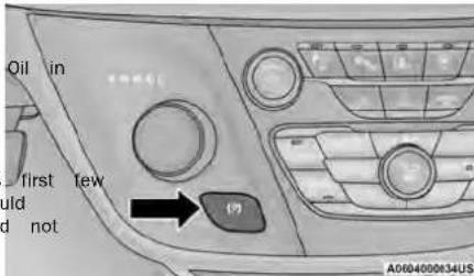
ElectricParkBrakeSwitch
cluster and the LED indicator on the switch will illuminate. If your foot is on the brake pedal, you may run a small amount of brake pedal movement while the parking brake is engaging.
The parking brake will release automatically when the ignition is cycled to the ON/RUN position, the transmission is in DRIVE or REVERSE, and the driver seat be buckled and an attempt is made to drive the vehicle away by pressing the accelerator pedal.
To release the parking brake manually, the ignition switch must be in the ON/RUN position. Press on the brake pedal, then push the parking brake switch momentarily. You may hear a sound from the back of the vehicle while the parking brake disengages. You
switch also notice a small amount of movement in the brake pedal. Once the parking brake is fully disen- aged, the Brake Warning Light in the instrument clus- er Light and the LED indicator on the switch will extinguish the switch
NOTEwhile
WHIPILL parking on a hill, it is important to turn the brakes toward the curb on a downhill grade and awa from the curb on an uphill grade. Apply the parking brake before placing the gear selector in PARK, otherwise the load on the transmission locking mechanism may make it difficult to move the gear selector out PARK. The parking brake should always be applied
NOTE:
- Manually, by applying the EPB switch.
- Automatically, by enabling the Auto Park Brake feature in the customer programmable features is held for longer than 180 seconds. The light gulsh upon releasing the switch.
The EPB is located in the integrated center stack. The Auto Park Brake feature is enabled, the parking brake will automatically engage whenever the transmission is placed into PARK. Once the parking brake is engaged, the Brake Warning Light in the instrument
WARNING!
- Never use the PARK position as a substitute parking brake. Always apply the parking brake when parked to guard against vehicle movement and possible injury or damage.
- When exiting the vehicle, always make sure ignition is in the OFF position, remove the from the vehicle, and lock your vehicle.
- Never leave children alone in a vehicle, or access to an unlocked vehicle. Allowing child be in a vehicle unattended is dangerous for ber of reasons. A child or others could be or fatally injured. Children should be warned touch the parking brake, brake pedal or the mission gear selector.
- Do not leave the key fob in or near the in a location accessible to children), and do leave the ignition in the ACC or ON/RUN child could operate power windows, other car or move the vehicle.
- Be sure the parking brake is fully disengaged before driving; failure to do so can lead to failure and a collision.
- Always fully apply the parking brake when your vehicle, or it may roll and cause damage injury. Also be certain to leave the transmit PARK. Failure to do so may allow the vehicle and cause damage or injury.
- Driving the vehicle with the parking brake engaged, or repeated use of the parking b slow the vehicle may cause serious damage brake system.
CAUTION!
IfforththeBrake System Warning Light remains thelly parking brake released, a brake system ton is indicated. Have the brake system so an authorized dealer immediately.
he
ey exceptional circumstances should make it need to engage the parking brake while the vehicle motion, push on the EPB switch for as long rent is desired. The Brake Warning Light will move until and a continuous chime will sound. The engine will also be illuminated automatically which vehicle remains in motion.
Törandisengage the parking brake while the vehi
motion, release the switch. If the vehicle is b complete stop using the parking brake, when vehicle reaches approximately 3 mph (4.8 km/h) parking brake will remain engaged.
mols, the unlikely event of a malfunction of the item, a yellow EPB Warning Light will illuminate may be accompanied by the Brake Warning Li
ng brake in this case, urgent service of the EPB required. Do not rely on the parking brake to vehicle stationary.
AutoParkBrake
The Electric Park Brake (EPB) can be program applied automatically whenever the vehicle is a standstill and the automatic transmission is pla PARK. Auto Park Brake is enabled and disable to the order selection through the customer programme features → page 101.
SafeHold
SafeHold is a safety feature of the Electric Park Brak-on (EVB) system that will engage the parking brake auto-malnically if the vehicle is left unsecured. If the auto-vice thatly transmission is not in PARK, the seat belt is unbuckled, the driver door is open, the vehicle is at standstill, and there is no attempt to press the brake necessaled or accelerator pedal, the parking brake will auto-le is automatically engage to prevent the vehicle from rolling.
g as SafeHold can be temporarily bypassed by pushing the all lippB while the driver door is open and brake pedal I the reassstop Once manually bypassed, SafeHold will while enabled again once the vehicle reaches 12 m (20 km/h) or the ignition is cycled to the OFF position
eang back to ON again.
BrakeServiceMode
We recommend having your brakes serviced by an authorized dealer. You should only make repairs for which you have the knowledge and the right equipment. You should only enter Brake Service Mode during brak service. t flash-
When servicing your rear brakes, it may be necessary stem is fold the or your technician to push the rear piston in the rear caliper bore. With the Electric Park Brake (EI system, this can only be done after retracting the EPI actuator. Fortunately, actuator retraction can be done
easily by entering Brake Service Mode in your vehicle ed to be page 101. This menu-based system will guide you a through the steps necessary to retract the EPB actuated in order to perform rear brake service. by CUS-
Brake Service Mode has requirements that must be met in order to be activated:
- The vehicle must be at a standstill.
- The parking brake must be unapplied.
- The transmission must be in PARK or NEUTRAL.
While in Brake Service Mode, the EPB Warning will flash continuously while the ignition switch is
When brake service work is complete, the following steps must be followed to reset the parking bra tem to normal operation:
- Ensure the vehicle is at a standstill.
- Press the brake pedal with moderate force.
- Apply the EPB.
WARNING!
You can be badly injured working on or around motor vehicle. Do only that service work for which have the knowledge and the right equipment. If have any doubt about your ability to perform a job, take your vehicle to a competent mechanic.
AUTOMATICTRANSMISSION
You must press and hold the brake pedal while out of PARK.
WARNING!
- Never use the PARK position as a substitute parking brake. Always apply the parking brake when exiting the vehicle to guard against vehi movement and possible injury or damage.
- Your vehicle could move and injure you and if it is not in PARK. Check by trying to move transmission gear selector out of PARK with the brake pedal released. Make sure the transmission is in PARK before exiting the vehicle.
(Continued)
Light ON
WARNING!
The transmission may not engage PARK if it isysmoving. Always bring the vehicle to a stop before shifting to PARK, and verify the transmission gear position indicator solidly in PARK (P) without blinking. Ensure that the completely stopped, and the PARK position erly indicated, before exiting the vehicle.
- It is dangerous to shift out of PARK of the engine speed is higher than idle space foot is not firmly pressing the brake per vehicle could accelerate quickly forward on which reuse. You could lose control of the vehicle someone or something. Only shift into service the engine is idling normally and firmly pressing the brake pedal.
- Unintended movement of a vehicle could those in or near the vehicle. As with a you should never exit a vehicle while the running. Before exiting a vehicle, always will complete stop, then apply the parking by the transmission into PARK, and turn the OFF. When the ignition is in the OFF transmission is locked in PARK, securing a vehicle against unwanted movement.
- When exiting the vehicle, always make a full ignition is in the OFF position, remove from the vehicle, and lock the vehicle.
- Never leave children alone in a vehicle, access to an unlocked vehicle. Allowing others in a vehicle unattended is dangerous because of reasons. A child or others could or fatally injured. Children should be aware touch the parking brake, brake pedal or mission gear selector.
the vehicle not leave the key fob in or near the vehicle complete in a location accessible to children), and at the leave the ignition in the ACC or ON/RUN position. indicates child could operate power windows, other vehicle ois move the vehicle.
r NEUTRAL if eed. If your
CAUTION!
cal, damage to the transmission may occur if the following precautions are not observed: vehicle • shift into or out of PARK or REVERSE only after gear vehicle has come to a complete stop. your foot is • Do not shift between PARK, REVERSE, NEUTRAL, or DRIVE when the engine is above idle speed. Injure • Before shifting into any gear, make sure your foot and vehicle is firmly pressing the brake pedal.
come to a
ake, shift ignition IGNITION PARK INTERLOCK
This vehicle is equipped with an Ignition Park Interlock the which requires the transmission to be in PARK before the ignition can be turned to the OFF position. This are helps the driver avoid inadvertently leaving the vehicle the keys of placing the transmission in PARK. This system also locks the transmission in PARK whenever the igni or wish is in the OFF position.
children to
for NOTE:um-
be Tseriodashmission will not come out of Park in ACC red than with the engine off. Ensure that the transmission the intraPARK, and the ignition is OFF(not in ACC position) before exiting the vehicle.
(Continued)
This vehicle is equipped with a BTSI that holds drive selects PARK while driving), the position indicator transmission gear selector in PARK unless the brake blink continuously until the selector is returned to are applied. To shift the transmission out of PARK, proper position, or the requested shift can be engine must be running and the brake pedal completed.
pressed. The brake pedal must also be pressed. The electronically controlled transmission adapts its from NEUTRAL into DRIVE or REVERSE when the high-speed schedule based on driver inputs, along with environment and road conditions. The transmission elec-
The transmission is controlled using a rotary electronic gear selector located on the center console. The 9-speed transmission has been developed
mission gear selector has PARK, REVERSE, NEUTRAL DRIVE, and LOW shift positions. Using the LOW position to a lower tower's driving experience and fuel economy. By manually downshifts the transmission to a lower gear design, some vehicle and driveline combinations based on vehicle speed. The transmission gear is the needs of current and future FWD/AWD vehicle
PRNDL) is displayed both above the gear selector and NINTH gear only in very specific driving situations in the instrument cluster. To select a gear range, simply
rotate the gear selector. Push down on the gear selector, only shift from DRIVE to PARK or REVERSE and then rotate it, to access the L position. You're a pedal is released and the vehicle also press the brake pedal to shift the transmission out. Be sure to keep your foot on the of PARK (or NEUTRAL, when stopped or moving when shifting between these gears.
speeds). To shift past multiple gear ranges at once
(such as PARK to DRIVE), simply rotate the gear selec-
tor to the appropriate detent. Select the DRIVE range for normal driving.
NOTE:
In the event of a mismatch between the gear selector position and the actual transmission gear (for example,
drives selects PARK while driving), the position indicator
wikes blink continuously until the selector is returned to the proper position, or the requested shift can be
no completed.
The electronically controlled transmission adapts its schedule based on driver inputs, along with environmental and road conditions. The transmission electronics are self-calibrating; therefore, the first few shifts on a new vehicle may be somewhat abrupt. This is normal condition, and precision shifts will develop within a few hundred miles (kilometers).
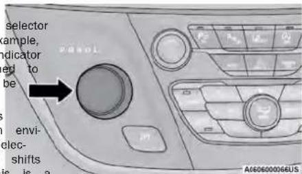
TransmissionGearSelector
4
GEAR RANGES
Do not press the accelerator pedal when shifting from PARK or NEUTRAL into another gear range.
NOTE:
After and selecting any gear range, wait a moment to allow the selected gear to engage before accelerating. This is especially important when the engine is cold.
aRARK(P)
This range supplements the parking brake by locking the transmission. The engine can be started in this range. Never attempt to use PARK while the vehicle i motion. Apply the parking brake when exiting the vehicle in this range.
When parking on a hill, apply the parking brake before shifting the transmission to PARK. As an added precaution, turn the front wheels toward the curb on a dow grade and away from the curb on an uphill grade.
When exiting the vehicle, always:
- Apply the parking brake.
- Shift the transmission into PARK.
- Turn the ignition off.
- Remove the key fob from the vehicle.
CAUTION!
- Before moving the transmission gear selector of PARK, you must start the engine, and the brake pedal. Otherwise, damage to the selector could result.
- DO NOT race the engine when shifting from or NEUTRAL into another gear range, as this damage the drivetrain.
out
press
CAUTION!
Towing the vehicle, coasting, or driving for a reason with the transmission in NEUTRAL can severe transmission damage.
Can Recreational Towing page 97. If Towing A Disabled Vehicle 181.
During cold temperatures, transmission operation may be modified depending on engine and transmission temperature as well as vehicle speed. This feature improves warm-up time of the engine and transmission to achieve maximum efficiency. Engagement of the torque converter clutch, and shifts into EIGHTH or NINTH gear, are inhibited until the transmission fluid is warm page 81. Normal operation will resume once the transmission temperature has risen to a suitable level.
LOW(L)
Use this range for engine braking when descending very steep grades. In this range, the transmission will downshift for increased engine braking. To access the LOW position, push down on the gear selector and rotate it fully clockwise.
The following indicators should be used to ensure that
you have properly engaged the transmission into PARK position:
- Look at the transmission gear position display verify that it indicates the PARK position (P), not blinking.
- With the brake pedal released, verify that the selector will not move out of PARK.
DRIVE(D)
This range should be used for most city and driving. It provides the smoothest upshifts and shifts, is and the best fuel economy. The transm automatically upshifts through all forward gears. DEBE position provides optimum driving character under all normal operating conditions.
If the transmission temperature exceeds normal ing limits, the transmission controller may mod Transmission shift schedule, reduce engine torque complete expand the range of torque converter engagement. This is done to prevent transmiss age due to overheating.
TransmissionLimpHomeMode
Transmission function is monitored electronically for historical conditions. If a condition is detected that down would result in transmission damage, Transmission Limp Home Mode is activated. In this mode, the transmission may operate only in a fixed gear, or may re-lease NEUTRAL. The Malfunction Indicator Light (MIL) may be illuminated. Limp Home Mode may allow the vehicle operate driven to an authorized dealer for service without damaging the transmission.
In the event of a momentary problem, the transmission will be reset to regain all forward gears by performing the following steps:
- Stop the vehicle. Trans-
REVERSE(R)
This range is for moving the vehicle backward. REVERSE only after the vehicle has come to a stop.
NEUTRAL(N)
Use this range when the vehicle is standing for longed periods with the engine running. Apply the ing brake and shift the transmission into PARK must exit the vehicle.
mision Temperature Warning Light will illuminate, 2a Shift the transmission into PARK, if possible. If not warning message will appear in the instrument cluster the transmission to NEUTRAL. Find the transmission may operate differently until the transmission cools down.
- Push and hold the ignition switch until the turns off.
- Wait approximately 30 seconds.
- Restart the engine.
- Shift into the desired gear range. If the no longer detected, the transmission will normal operation.
NOTE:
Even if the transmission can be reset, we recommend
that you visit an authorized dealer at your sible convenience. An authorized dealer has equipment to assess the condition of your sion. If the transmission cannot be reset, dealer service is required.
ACTIVENOISECANCELLATION
Your vehicle is equipped with an Active Noise Cat ion system. This system is designed to address N exhaust and engine noise. The system relies on 10 monophones embedded in the headliner, which more exhaust and engine noise, and assists an onboard quency generator, which creates counteracting sound waves in the audio system's speakers. This helps the vehicle quiet at idle and during drive.
POWERSTEERING
The electric power steering system will provide increased vehicle response and ease of maneuverity. The power steering system adapts to differing conditions.
cates that the vehicle needs to be taken to an authorized dealer for service. It is likely the vehicle has lo power steering assistance page 66.
NOTE: four
Even if the power steering assistance is no longer operational, it is still possible to steer the vehicle. Under these conditions there will be a substantial increase in steering effort, especially at low speeds and during parking maneuvers.
- The power steering system is fully electric; requires no power steering fluid.
- If the condition persists, see an authorized abil for service.
- The power steering system is fully electric; requires no power steering fluid.
- If the condition persists, see an authorized abil for service.
4
TorqueConverterClutch
A feature designed to improve fuel economy has included in the automatic transmission on your A clutch within the torque converter engages acally at calibrated speeds. This may result in a different feeling or response during normal operat the upper gears. When the vehicle speed drops ing some accelerations, the clutch automatically disengages.
NOTE:
The torque converter clutch will not engage until engine and/or transmission is warm (usually after 3 miles [2 to 5km ] of driving). Because the speed is higher when the torque converter clutch engaged, it may seem as if the transmission is ing properly when the vehicle is cold. This is The torque converter clutch will function normally the powertrain is sufficiently warm.
| been vehicle. | WARNING! |
| continued operation with reduced assist could slightly risk to yourself and others. Service s obtained as soon as possible. | |
If the Steering icon is displayed and the "POWER"
STEERING SYSTEM OVER TEMP" message is displayed on the instrument cluster screen, this indicates a
temperature condition in the power steering system Once, driving conditions are safe, pull over and
vehicle to idle for a few moments until the icon a
engine sage turn off page 65.
If the "SERVICE POWER STEERING" or "POWER STEERING ASSIST OFF - SERVICE SYSTEM" message and a steering wheel
are displayed on the instrument cluster screen, it
Stop/StartSystem—IfEquipped
The Stop/Start function is designed to save fuel and reduce emissions. The system will stop the engine automatically during a vehicle stop if the required condition could reebemet. Releasing the brake pedal or shifting out of DRIVE will automatically restart the engine.
AUTOSTOP MODE
and Stop/Start feature is enabled after every normal customer engine start. At that time, the system will go into STOP/START READY and if all other conditions are left, the can go into a STOP/START AUTOSTOP ACTIVE.
and mes- ToActivateAutoSTOP/START,TheFollowingMust Occur:
- The system must be in STOP/START READY state. A STOP/START READY message will be displayed in the instrument cluster within the Stop/Start section t indi- page 70.
• The vehicle must be completely stopped.
- The gear selector must be in a forward gear brake pedal pressed.
The engine will shut down, the tachometer will the zero position and the Stop/Start telltale will nate indicating you are in Autostop. Customer se will be maintained throughout the Auto Stop/Start process.
POSSIBLE REASONS THE ENGINE DOES NOT AUTOSTOP
Prior to engine shut down, the system will check safety and comfort conditions for Stop/Start and ensure they are fulfilled. Detailed information about operation of the Stop/Start system may be viewed the instrument cluster display Stop/Start screen. In following situations the engine will not stop:
- If Stop/Start is manually disabled by the Stop OFF button.
- Driver's seat belt is not buckled.
- Driver's door is not closed.
- Battery temperature is too warm or cold.
- Battery charge is low. During this time a me will display "Stop/Start Not Ready Battery Charge
• The vehicle is on a steep grade. - Cabin heating or cooling is in process and a acceptable cabin temperature has not been achieved.
- HVAC is set to full defrost mode at a high speed.
• HVAC is set to MAX A/C. -
Engine has not reached normal operating temperature.
-
The transmission is not in a forward gear.
- aniodthis open.
- Brake pedal is not pressed with sufficient move to Accelerator pedal input.
- Engine temperature is too high.
- 5 mph (8 km/h) threshold has not been from previous Autostop.
• Steering angle is beyond threshold.
It may be possible for the vehicle to be driven times without the Stop/Start system going into a START READY state under more extreme conditions the many terms previously listed.
TO THE START THE ENGINE WHILE d in AUTO STOP/START
While in a forward gear, the engine will state pedal is released or the accelerator pressed. The transmission will automatically upon engine restart.
ConditionsThatWillCauseTheEngineToStartAutomaticallyWhileInAutoStop/Start:
- The transmission selector is moved out of ssage to maintain cabin temperature comfort.
• HVAC is set to full defrost mode.
HVAC system temperature or fan speed is manually adjusted.
- Battery voltage drops too low. During this time a message will display "Stop/Start Not Ready Battery Charging".
- Stop/Start OFF switch is pushed.
- A Stop/Start system error occurs.
• Steering angle beyond threshold.
(二)
ne a
battery
(1)基因通过控制 通过控制
[Non-Text]
项目
合计
The Ground Truth image displays a single, solid horizontal line. According to Rule 2 (UNDERSCORE & LINE RULES), this is a stylistic or background line, not a placeholder underscore. Therefore, the OCR result must ignore it and output nothing or only meaningful text. The provided OCR content is "____", which consists of four underscores. This is an incorrect interpretation of the line as a placeholder, violating the rule that stylistic lines must be ignored. The OCR has hallucinated placeholder underscores where none exist in the GT. Hence, the OCR result is inconsistent with the Ground Truth.
TO MANUALLY TURN OFF THE STOP/START SYSTEM
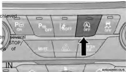
Stop/StartOFFSwitch
Push the Stop/Start OFF switch (located on the switch break). The light on the switch will illuminate. The "STOP/START OFF" message will appear in the instrument cluster display and the Autostop mode will be disabled → page 65.
NOTE:
The Stop/Start system will reset itself back to the ON position every time the ignition is turned OFF and back
ON manually
TO MANUALLY TURN ON THE STOP/START SYSTEM
After turning off the Stop/Start system, push the Start OFF switch again (located on the switch b The light on the switch will turn off.
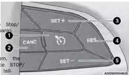
CruiseControlButtons
SYSTEM MALFUNCTION
If there is a malfunction in the Stop/Start system will not shut down the engine. A "Service START System" message and a yellow Stop/Start tale will appear in the instrument cluster display page 60.
If the "Service STOP/START System" message appears
in the instrument cluster display, have the system
checked by an authorized dealer.
CRUISECONTROLSYSTEMS— IFEQUIPPED
Your vehicle may be equipped with the Cruise system for cruising at a constant preset speed.
CRUISE CONTROL
When engaged, the Cruise Control takes over actor operations at speeds greater than 20 mph (32 km/h).
The Cruise Control buttons are located on the of the steering wheel.
1 - On/Off
2 - CANC/Cancel
3 - SET (+)/Accel
4 - RES/Resume
5 - SET (-)/Decel
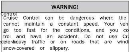
ToActivate
Push the on/off button to activate the Cruise Control. mph.
The Cruise Control Set Indicator Light in the instrument. The button is continually pushed, the set speed cluster display will illuminate. To turn the system will continue to adjust in 5 mph increments until 1 push the on/off button a second time. The Cruise button is released. The new set speed is reflected in the Trol Set Indicator Light will turn off. The system should be turned off when not in use.
WARNING!
Leaving the Cruise Control system on when not in us is dangerous. You could accidentally set the system or cause it to go faster than you want. You could control and have an accident. Always leave the system off when you are not using it.
ToSetADesiredSpeed
Turn the Cruise Control on.
NOTE:
The vehicle should be traveling at a steady speed-up on level ground before pushing the SET (+) or SET (button.
When the vehicle has reached the desired speed, push the SET (+) or SET (-) button and release. Release t accelerator and the vehicle will operate at the selected speed.
ToVaryTheSpeedSetting
systemIncreaseOrDecreaseTheSetSpeed
When the Cruise Control is set, you can increase spe by using the SET (+)button. or decrease speed by pushing the SET (-)button.
U.S.Speed(mph)
- Pushing the SET (+), or SET (-)button once will result in a 1 mph speed adjustment. Each subsequent tap of the button results in an adjustment (
MetricSpeed(km/h)
- Pushing the SET (+), or SET (-) button once will result in a 1 km/h speed adjustment. Each subsequent tap of the button results in an adjust 1 km/h.
- If the button is continually pushed, the set will continue to adjust in 10 km/h increment the button is released. The new set speed reflected in the instrument cluster display.
ToResumeSpeed
To resume a previously set speed, push the RES and release. Resume can be used at any speed of 20 mph (32 km/h).
ToDeactivate
A tap on the brake pedal, pushing the CANC normal brake pressure will deactivate the Cruise trol system without erasing the set speed from Pushing the on/off button or placing the ignition OFF position erases the set speed from memor
- Automatic brakes will not be available if there is a faulted condition detected with the ParkSense Park button. Assist system or the Braking System Module.
- The automatic braking function may not provide enough vehicle deceleration to avoid colliding with a detected obstacle depending on vehicle speed, road conditions, and brake capability.
- The automatic braking function may not be applied meaning enough for moving obstacles that approach the force of the vehicle from the left and/or right sides
- The automatic braking function can be enabled/ disabled from the Customer Programmable Features section of the Uconnect system.
- ParkSense will retain its last known configuration state for the automatic braking function through ignition cycles.
The automatic braking function is intended to assist the driver in avoiding possible collisions with detected obstacles when backing up in REVERSE gear.
PARKSENSERARPARKASSIST— IFEQUIPPED
ToAccelerateForPassing
While the Cruise Control is set, press the acceptance pass as you would normally. When the pedal is released, the vehicle will return to the set speed
USINGCRUISECONTROLONHILLS
The transmission may downshift on hills to main vehicle set speed. The Cruise Control system maintains speed up a down hills. A slight speed change on moderate normal. On steep hills, a greater speed loss or occur so it may be preferable to drive without Control.
WARNING!
Cruise Control can be dangerous where the sys cannot maintain a constant speed. Your vehicle go too fast for the conditions, and you could trol and have an accident. Do not use Cruise in heavy traffic or on roads that are winding, snow-covered or slippery.
The ParkSense Rear Park Assist system provides and audible indications of the distance between rear fascia/bumper and a detected obstacle who is backing up (e.g. during a parking maneuver). If
vehicle is equipped with an automatic transmission the cruise vehicle brakes may be automatically applied and NOTE.
released when performing a parking maneuver if the system is designed to assist the driver and no system detects a possible collision with an obstacle to substitute the driver.
NOTE:
The driver can override the automatic braking condition by pressing the gas pedal, turning Park Control via ParkSense switch, or changing the game, the automatic brakes are being applied.
- Automatic brakes will not be available if Ele Stability Control (ESC) is not available.
- The driver must stay in full control of the vehicle's acceleration and braking and is responsible for controlling the vehicle's movements. - For limitations of this system and recommendations/ precautions, see page 88.
ParkSense will retain the last system state (enabled or denied) from the last ignition cycle when the ignition is changed to the ON/RUN position.
ParkSense can be active only when the gear selector is PARKSENSE DISPLAY
in REVERSE. If ParkSense is enabled at this gear selector position, the system will remain active until when the vehicle is in REVERSE and an obstacle has vehicle speed is increased to approximately 7 mph (11 km/h) or above. When in REVERSE and above the system status, and remain on until the vehicle is system's operating speed, a warning will appear moved out of REVERSE.
the instrument cluster display indicating the vehicle the system will indicate a detected obstacle by showing speed is too fast. The system will become active single arc in one or more regions based on the obsta- if the vehicle speed is decreased to speeds less than distance and location relative to the vehicle.
approximately 6 mph (9 km/h).
If an obstacle is detected in the center rear region, the
display will show a single solid arc in the center rear region and will produce a one-half second tone. As the
PARKSENSE SENSORS
The four ParkSense sensors, located in the rear fascia/bumper, monitor the area behind the vehicle that within the sensors' field of view. The sensors of one defect obstacles from approximately 12 inches (30 cm) if up to obstacle is detected in the left and/or right rear 79 inches (200 cm) from the rear fascia/bumperegion, then the display will show a single flashing arc in the horizontal direction, depending on the location, type and/or right rear region and will produce a fast and orientation of the obstacle. As the vehicle moves closer to the obstacle, the
PARKSENSE WARNING DISPLAY
continuous.
The ParkSense Warning screen will only be displayed if continuous.
Sound and Display is selected from the Customer-
Programmable Features section of the Uconnect sys-
tem → page 100.
The ParkSense Warning screen is located within the instrument cluster display page 60. It provides
visual warnings to indicate the distance between the rear fascia/bumper and the detected obstacle.
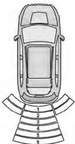
RearParkSenseArcs
A0628000179US
1 — Continuous Tone/Flashing Arc 4 — Slow Tone/Solid Arc
2 - Fast Tone/Flashing Arc 5 - Slow Tone/Solid Arc
3 - Fast Tone/Flashing Arc 6 - Single 1/2 Second Tone/Solid Arc
The vehicle is close to the obstacle when the warning display shows one flashing arc and sounds a continuous tone. The following chart shows the warning alert operation when the system is detecting an obstacle:
| WARNINGALERTS | |||||||
| Rear Distance (inches/cm) | Greater than 79 inches (200 cm) | 79-59 inches (200-150 cm) | 59-47 inches (150-120 cm) | 47-39 inches (120-100 cm) | 39-25 inches (100-65 cm) | 25-12 inches (65-30 cm) | Less than 12 inches (30 cm) |
| Arcs — Left | None None None | None None 2nd | Flashing 1st Flashing | ||||
| Arcs — Center | None 6th Solid | 5th Solid 4th Solid | 3rd Flashing 2nd Flashing 1st Flashing | ||||
| Arcs — Right | None None None | None None 2nd | Flashing 1st Flashing | ||||
| Audible Alert Chime | None | Single 1/2 Second Tone (for rear center only) | Slow (for rear center only) | Slow (for rear center only) | Fast (for rear center only) | Fast Continuous | |
| Radio Volume Reduced | No Yes Yes Yes | Yes Yes | Yes | ||||
NOTE:
ParkSense will reduce the volume of the radio, if on, when the system is sounding an audio tone.
ENABLING AND DISABLING PARKSENSE

ParkSense can be enabled and disabled with the ParkSense switch, located on the ParkSense switch is pushed, and requires service, vehicle graphic will remain displayed for as long as the LED will blink momentarily, and vehicle is in REVERSE.
switch panel below the Uconnect display.the LED will be on.
OFF When the ParkSense switch is pushed disable the system, the instrument cluster will the "ParkSense Off" message for approximately seconds. When the gear selector is moved to and the system is disabled, the instrument cl play will show the "ParkSense Off" message for as the vehicle is in REVERSE.
to SERVICE THE PARKSENSE REAR display PARK ASSIST SYSTEM
REVERSE During vehicle start up, when the ParkSense Reaves Park to the Assist system has detected a faulted condition, the "Park as long instrument cluster will actuate a single chime, once per ignition cycle, and it will display the "ParkSense Unavail- able Wipe Rear Sensor" or the "ParkSense Unavailable Service Required". When the gear selector is moved to REVERSE and the system has detected a faulted condi- tion, the instrument cluster dispage 60 will
If "ParkSense Unavailable Wipe Rear Sensor" appears in the instrument cluster display, make sure the outer surface and the underside of the rear fascia/bumper is clean and clear of snow, ice, mud, dirt, or other observations and then cycle the ignition. If the message contains Park appear, see an authorized dealer.
If "ParkSense Unavailable Service Required" appears in ice per the instrument cluster display, see an authorized
nava alor
able.
al.
a to
cond
[Non-Text]
CLEANING THE PARKSENSE SYSTEM
Clean the ParkSense sensors with water, car wash soap, and a soft cloth. Do not use rough or ha Do not scratch or poke the sensors.
PARKSENSE SYSTEM USAGE PRECAUTIONS
NOTE:
- Ensure that the rear fascia/bumper is free of ice, mud, dirt, and debris to keep the ParkS system operating properly.
- Jackhammers, large trucks, and other vibrations could affect the performance of ParkSense.
- When you turn ParkSense off, the instrument ter will display "ParkSense Off". Furthermore, you turn ParkSense off, it remains off until it on again, even if you cycle the ignition.
- When you move the gear selector to the RE position and ParkSense is turned off, the inst cluster display will show "ParkSense Off" for a as the vehicle is in REVERSE.
-
ParkSense, when on, will reduce the volume of radio when it is sounding a tone.
-
Clean the ParkSense sensors regularly, taking not to scratch or damage them. The sensors not be covered with ice, snow, slush, mud, debris. Failure to do so can result in the working properly. The ParkSense system might detect an obstacle behind the fascia/bumper, could provide a false indication that an obstacle behind the fascia/bumper.
- ParkSense should be disabled when the liftgat the open position.
- Use the ParkSense switch to turn the ParkSense system off if objects such as bicycle carriers, hitches, etc., are placed within 12 inches (30 inches) the rear fascia/bumper. Failure to do so can in the system misinterpreting a close object a blockage or sensor problem, causing the "ParkSense Unavailable Wipe Rear Sensor" message to be displayed in the instrument cluster display.
turn
WARNING!
Drivers must be careful when backing up even when using ParkSense. Always check carefully behind your vehicle, look behind you, and be to check for pedestrians, animals, other vehicle obstructions, and blind spots before backing u You are responsible for safety and must cont to pay attention to your surroundings. Failure so can result in serious injury or death.
| caremust | WARNING! |
| CartBefore using ParkSense, it is strongly recommended that the ball mount and hitch ball assembly be disconnected from the vehicle when the or vehicle is not used for towing. Failure to do so a result in injury or damage to vehicles or obstacles because the hitch ball will be much closer to the obstacle than the rear fascia/bumper when the vehicle sounds the continuous tone. Also, the sensors could detect the ball mount and hitch ball assembly, depending on its size and shape, giving a false indication that an obstacle is behind the vehicle. | |
as a
CAUTION!
- ParkSense is only a parking aid and it is unable to recognize every obstacle, including small obstacles. Parking curbs might be temporarily detected or not detected at all. Obstacles located above or below the sensors will not be detected when they are in close proximity. - The vehicle must be driven slowly when using parkSense in order to be able to stop in time with an obstacle is detected. It is recommended that the driver looks over his/her shoulder when using parkSense.
(Continued)
PARKVIEWREARBACKUPCAMERA
The ParkView Rear Back Up Camera allows you an on-screen image of the rear surroundings of vehicle whenever the gear selector is put into. The image will be displayed on the touchscreen along with a caution note "Check Entire Surround across the top of the screen. After five seconds note will disappear. The ParkView Rear Back Up era is located on the rear of the vehicle above license plate.
NOTE:
The ParkView Rear Back Up Camera has program modes of operation that may be selected through Uconnect system→page 100.
When the vehicle is shifted out of REVERSE with a delay turned off, the rear camera mode is and the previous screen appears.
When the vehicle is shifted out of REVERSE with era delay turned on, the camera image will come be displayed for up to 10 seconds unless the speed exceeds 8 mph (13 km/h), the vehicle is into PARK, or the ignition is placed in the OFF
A touchscreen X button to disable the camera made available when the vehicle is not in REVE gear. Display of the camera image after shifting REVERSE can be disabled through the camera set menu with the Uconnect system.
When enabled, active guidelines are overlaid on image to illustrate the width of the vehicle and jected backup path based on the steering wheel position.
Different colored zones indicate the distance to of the vehicle.
The following table shows the approximate dist. for each zone:
| to ZoneDistanceToTheRearOfTheVehicle | |
| your Red 0-1 ft (0-30 cm) | |
| disPlow 1 ft - 6.5 ft (30 cm - 2 m) | |
| dingsGreen 6.5 ft or greater (2 m or greater) |
NOTE
If the snow, ice, mud, or any foreign substance by the camera lens, clean the lens, rinse with dry with a soft cloth. Do not cover the lens.
| hmable the WARNING! |
| Drivers must be careful when backing up e using the ParkView Rear Back Up Camera. check carefully behind your vehicle, and be check for pedestrians, animals, other vehicles, obstructions, or blind spots before backing u h cam are responsible for the safety of your surro tinue to and must continue to pay attention while b vehicle failure to do so can result in serious inju s shifted |
F position.
| Image is ERSE CAUTION! |
| out of•To avoid vehicle damage, ParkView should ettings used as a parking aid. The ParkView can unable to view every obstacle or object the drive path.•its pro-•To avoid vehicle damage, the vehicle must driven slowly when using ParkView to be stop in time when an obstacle is seen.the mended that the driver look frequently over her shoulder when using ParkView. |
REFUELINGTHEVEHICLE
There is no fuel filler cap. Two flapper doors inside pipe seal the system.
| WARNING! |
| Never have any smoking materials lit in vehicle when the fuel door is open or thds being filled. |
| Never add fuel when the engine is runnin violation of most state and federal fire tions and may cause the Malfunction IndiLight to turn on. |
| When fire may result if fuel is pumped into container that is inside of a vehicle. You burned. Always place fuel containers on thground while filling. |

| g up. | CAUTION! |
| to avoid fuel spillage and overfilling, do not the fuel tank after filling. | |
"top off"
- Put the vehicle in PARK and switch the ignition C only be a 2 is push the center-rear edge of the fuel filler door in your (3 o'clock position) and release to open. Rotate to full open position.
It is recom-
r his/
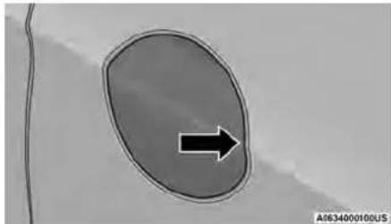
natural_image
Simple diagram showing an oval shape with a black arrow pointing right, no text or symbols present.FuelFillerDoor
- Insert the fuel nozzle fully into the filler nozzle opens and holds both flapper doors refueling.
- When the fuel nozzle "clicks" or shuts off, tank is full.
- Keep the nozzle in the filler for five second the nozzle clicks to allow fuel to drain from nozzle.
- Remove the fuel filler nozzle.
- To close the fuel filler door, push the ce edge (3 o'clock position) of the fuel filler then release. The fuel filler door will latch
NOTE:
In certain cold conditions, ice may prevent the door from opening. If this occurs, lightly push fuel filler door around the perimeter to break buildup.
VEHICLELOADING
CERTIFICATION LABEL
As required by National Highway Traffic Safety tration regulations, your vehicle has a certificat affixed to the driver's side door or pillar.
This label contains the month and year of m Gross Vehicle Weight Rating (GVWR), front and Gross Axle Weight Rating (GAWR), and Vehicle cation Number (VIN). A Month-Day-Hour (MDH) is included on this label and indicates the M and Hour of manufacture. The bar code that
on the bottom of the label is your VIN. e: the
GrossVehicleWeightRating(GVWR)
The GVWR is the total permissible weight of the fuel including driver, passengers, vehicle, options and The label also specifies maximum capacities of
and after GAWR. Total load must be limited and front and rear GAWR are not exceeded.
Payload
The payload of a vehicle is defined as the load weight a truck can carry, including the one and liver, all passengers, options and cargo.
GrossAxleWeightRating(GAWR)
The GAWR is the maximum permissible load on the
front and rear axles. The load must be distributed in the cargo area so that the GAWR of each axle is not exceeded.
Each axle GAWR is determined by the components in the system with the lowest load carrying capacity (axle springs, tires or wheels). Heavier axles, or suspension components sometimes specified by purchasers for increased durability, do not necessarily increase the engine's GVWR.
TireSize
The tire size on the Vehicle Certification Label represents the actual tire size on your vehicle. Replacement tires must be equal to the load capacity of this tire number
RimSize
This is the rim size that is appropriate for the tire listed.
InflationPressure
This is the cold tire inflation pressure for your vehicle for all loading conditions up to full GAWR.
GVWR CurbWeight
The curb weight of a vehicle is defined as the total weight of the vehicle with all fluids, including vehicle vehicles at full capacity conditions, and with no occupants' right cargo loaded into the vehicle. The front and rear weight values are determined by weighing your vehicle on a commercial scale before any occupants or cargo are added.
Loading
The actual total weight and the weight of the front and
rear of your vehicle at the ground can best be in other- section you will find safety tips and information. The GCR is the total permissible weight of your mined by weighing it when it is loaded and ready limits to the type of towing you can reasonably do with your vehicle. Before towing a trailer, carefully with your vehicle.
The entire vehicle should first be weighed on cial scale to ensure that the GVWR has not exceeded. The weight on the front and rear vehicle should then be determined separately if sure that the load is properly distributed over and rear axle. Weighing the vehicle may show GAWR of either the front or rear axles has
exceeded but the total load is within the sp GVWR. If so, weight must be shifted from fr rear to front as appropriate until the specified limitations are met. Store the heavier items d and be sure that the weight is distributed e all loose items securely before driving.
Improper weight distributions can have an adverse effect on the way your vehicle steers and has the way the brakes operate.
TRAILERTOWING
front and open detir- section you will find safety tips and reely links to the type of towing you can r with your vehicle. Before towing a trailer, ca
review this information to tow your load as a commer and safely as possible.
- The maintenance the New Vehicle Limited Warranty age, follow the requirements and recommendation this manual concerning vehicles used for train the front
that the COMMON TOWING DEFINITIONS
ified the following trailer towing related definitions to your understanding the following information weight
W Gross Vehicle Weight Rating(GVWR)
GWR is the total allowable weight of your includes driver, passengers, cargo and tongue. The total load must be limited so that you exceeds the GWR page 90.
GrossCombinationWeightRating (GCWR)
formation The GCWR is the total permissible weight of your bably do vehicle and trailer when weighed in combination. ly
GrossAxleWeightRating(GAWR)
The GAWR is the maximum capacity of the front and rear axles. Distribute the load over the front and rear axles evenly. Make sure that you do not exceed either front or rear GAWRpage 90.
| assist | WARNING! |
| It is important that you do not exceed the front or rear GAWR. A dangerous driving co result if either rating is exceeded. You could feel This the vehicle and have a collision. | |
| 4 |
| maximum |
| ndition car |
| lose co |
TongueWeight(TW)
The TW is the downward force exerted on the hitch by the trailer. You must consider this as part of the thin of you all vehicle.
TrailerFrontalArea
The Frontal Area is the maximum height multiplied by quite your maximum width of the front of a trailer.
GrossTrailerWeight(GTW)
GTW is the weight of the trailer plus the cargo consumables and equipment (permanent
e. GVWR temporary) loaded in or on the trailer in it do parts ready for operation" condition.
to The recommended way to measure GTW is your fully loaded trailer on a vehicle scale. The of the trailer must be supported by the sc
WARNING!
Do not load your vehicle any heavier than or the maximum front and rear GAWR. If on your vehicle can break, or it can char your vehicle handles. This could cause you control. Overloading can shorten the life of vehicle.
e weight
[Non-Text]
TrailerSwayControl(TSC)
The TSC can be a mechanical telescoping link be installed between the hitch receiver and the tongue that typically provides adjustable friction ated with the telescoping motion to dampen an unwanted trailer swaying motions while traveling. The electronic TSC (if equipped) recognizes a trailer and automatically applies individual wheel brakes and/or reduces engine power to attempt eliminate the trailer sway.
Weight-DistributingHitch
that Weight-Distributing Hitch works by applying level
thadlegh spring (load) bars. They are typically use
sheavier loads to distribute trailer tongue weight
tow vehicle's front axle and the trailer axle(s).
used in accordance with manufacturer's directions,
provides for a more level ride, offering more co
steering and brake control thereby enhancing tow
safety. The addition of a friction/hydraulic sway
also dampens sway caused by traffic and crosswind information.
and contributes positively to tow vehicle and trailer sta
bility. TSC and a Weight-Distributing (load equalizing)
Hitch are recommended for heavier TW and may be
WARNING!
- For improperly adjusted Weight-Distributing Hitch system may reduce handling, stability, braking performance, and could result in a collision. - With Weight-Distributing Hitch systems may not be comparable with surge brake couplers. Consult with your hitch and trailer manufacturer or a reputable
Weight-CarryingHitch
A Weight-Carrying Hitch supports the trailer tongue
weight, just as if it were luggage located at a hitch ball configuration/loading to comply with GAWR
or some other connecting point of the vehicle. These requirements.
kinds of hitches are commonly used to tow small and
medium sized trailers.
TRAILER HITCH CLASSIFICATION
The following chart provides the industry standard for the maximum trailer weight a given trailer hitch class can tow and should be used to assist you in selecting the correct trailer hitch for your intended towing condition.
| TrailerHitchClassificationDefinitions | |
| ClassMax.TrailerHitchIndustryStandards | |
| Class I - Light Duty 2,000 lb (907 kg) | |
| Class II - Medium Duty 3,500 lb (1,587 kg) | |
| Class III - Heavy Duty 6,000 lb (2,721 kg) | |
| Class IV - Extra Heavy Duty 10,000 lb (4,535 kg) | |
| Refer to the “Trailer Towing Weights (Maximum Trailer Weight Ratings)” chart for the Maximum Gross Trailer Weight (GTW) towable for your given drivetrain. | |
| All trailer hitches should be professionally installed on your vehicle. | |
The following chart provides the maximum trailer weight ratings towable for your given drivetrain.
| Engine/TransmissionTrailer TowPackageGCWR FrontalAreaMaximumGTWM MaximumTrailerTW | |||||||||||||
| 3.6L/Automatic | Yes | 8,600 | lb | (3,900 kg) | 40 sq ft | (3.72 sq m) | 3,600 lb | (1,632 kg) | 360 lb | (163 kg) | |||
| No | 6,500 | lb | (2,948 kg) | 40 sq ft | (3.72 sq m) | 1500 lb | (680 kg) | 149 | lb | (67 kg) | |||
| Refer to local laws for maximum trailer towing speeds. | |||||||||||||
NOTE:
The trailer tongue weight must be considered as part of the combined weight of occupants and cargo, and should never exceed the weight referenced on the Tire And Loading InformationPlacard.
VEHICLE LOADING CHART
Follow these steps to determine the total weight the vehicle can carry:
- Determine the cargo capacity of your vehicle.
○ Load Capacity = GVWR - Curb (weight of vehicle, full fluids, no occupants).
- Determine occupant count.
○ For calculation purposes, average weight of an occupant is 150 lb (68 kg).
EXAMPLE:
• GVWR = 6,005 lb (2,723 kg)
• CURB = 4,500 lb (2,041 kg)
- Load Capacity = GVWR - CURB = 6,005 lb (2,723 kg) - 4,500 lb (2,041 kg) = 1,505 lb (682 kg)
4 Occupants (at 150 lb [68 kg]) + Max Trailer =
- 1,505 lb (682 kg) – 600 lb (272 kg) (4 x 150 lb [68 kg]) – 360 lb (163 kg) (10% of 3,600 lb [1,632 kg]) = 545 lb (247 kg) of cargo in vehicle
| NumberOfPersons/WeightOfOccupantsMaxCargoNoTrailer | MaxTrailerTW,Max Trailer | MaxCargoWithMax TrailerTW360lb (163kg) | |
 2People/300lb(136kg) 2People/300lb(136kg) |  1,205lb(546kg) 1,205lb(546kg) | 1,205 lb (546 kg) - 360_ lb (163 kg) = 845 lb (383 kg) |  845lb(383kg) 845lb(383kg) |
 4people/600lb(272kg) 4people/600lb(272kg) |  955lb(433kg) 955lb(433kg) | 955 lb (433 kg) - 360 lb (163 kg) = 545 lb (247 kg) |  545lb(247kg) 545lb(247kg) |
 7people/1,050lb(476kg) 7people/1,050lb(476kg) |  455lb(206kg) 455lb(206kg) | 455 lb (206 kg) - 360 lb (163 kg) = (43 kg) |  95lb(43kg) 95lb(43kg) |
- Make sure loading does not exceed GAWR of front or rear axles.
- GAWR is found on the certification label affixed to the driver's side door jamb.
TRAILER AND TONGUE WEIGHT TOWING REQUIREMENTS
Never exceed the maximum tongue weight stamp to promote proper break-in of your new vehicle your fascia/bumper or trailer hitch. train components, the following guidelines are
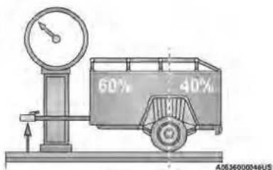
WeightDistribution
Consider the following items when computing the weight on the rear axle of the vehicle:
• The tongue weight of the trailer.
- The weight of any other type of cargo or put in or on your vehicle.
• The weight of the driver and all passengers.
NOTE:
Remember that everything put into or on the adds to the load on your vehicle. Also, additional factory-installed options or dealer-installed options must be considered as part of the total load vehicle → page 210.
d promote proper break-in of your new vehicle train components, the following guidelines are recommended.
CAUTION!
- Do not tow a trailer at all during the (805 km) the new vehicle is driven. The axle or other parts could be damaged.
- Then, during the first 500 miles (805 km) trailer is towed, do not drive over 50 mph (80 km/h) and do not make starts at full. This helps the engine and other parts of a vehicle wear in at the heavier loads.
Perform the maintenance listed in "Scheduled Sing" → page 184. When towing a trailer, never the GAWR or GCWR ratings.
equipment
WARNING!
Improper towing can lead to a collision. Follow guidelines to make your trailer towing as safe sible:
File Make certain that the load is secured in the-
al and will not shift during travel. When trailing
cargo that is not fully secured, dynamic load
on your occur that may be difficult for the driver
trol. You could lose control of your vehicle an
a collision.
WARNING!
When hauling cargo or towing a trailer, do not overload your vehicle or trailer. Overloading can cause a loss of control, poor performance or damage to brakes, axle, engine, transmission, steering, suspension, chassis structure or tires.
Safety chains must always be used between your vehicle and trailer. Always connect the chains to the hook retainers of the vehicle hitch. Cross the chains under the trailer tongue and allow enough that slack for turning corners.
- Vehicles with trailers should not be parked. 4
- grade. When parking, apply the parking brake on the tow vehicle. Put the tow vehicle transmission in PARK. For four-wheel drive vehicles, make sure the transfer case is not in NEUTRAL. Always, block or
• GCWR must not be exceeded.
- Totalweightmustbedistributedbetweenthetow vehicleandthetrailersuchthatthefollowingfour ratingsarenotexceeded:
these GVWR
GTW
as Opos-GAWR
○ Tongue weight rating for the trailer hitch utilized trailer
(Continued)
TowingRequirements—Tires
- Do not attempt to tow a trailer while using pact spare tire.
- Do not drive more than 50 mph (80 km/h) towing while using a full size spare tire.
- Proper tire inflation pressures are essential to safe and satisfactory operation of your vehicle.
- Check the trailer tires for proper tire inflation sures before trailer usage.
- Check for signs of tire wear or visible tire before towing a trailer.
- Replacing tires with a higher load carrying capacity will not increase the vehicle's GVWR and GAWR limits.
- For further information page 207.
TowingRequirements—TrailerBrakes
- Do notinterconnect the hydraulic brake system vacuum system of your vehicle with that of trailer. This could cause inadequate braking and possible personal injury.
- An electronically actuated trailer brake controller required when towing a trailer with electronica actuated brakes. When towing a trailer equipp
with a hydraulic surge actuated brake system, electronic brake controller is not required.
- Trailer brakes are recommended for trailers over 1,000 lb (453 kg) and required for trailers of 2,000 lb (907 kg).
WARNING!
- Do not connect trailer brakes to your vehicle hydraulic brake lines. It can overload your system and cause it to fail. You might break when you need them and could the accident.
- Towing any trailer will increase your stopp presence. When towing, you should allow for tional space between your vehicle and the amage front of you. Failure to do so could accident.
The electrical connections are all complete to the vehicle but you must mate the harness to a trailer of nector. Refer to the following illustrations.
brake NOTE: not have
have • a disconnect the trailer wiring connector from the vehicle (or any other device plugged into vehicle's electrical connectors) before launching a boat into water.
e vehicle be sure to reconnect once clear from water area. result in an
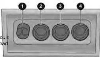
M0636000043US
CAUTION!
If the trailer weighs more than 1,000 lb loaded, it should have its own brakes and be of adequate capacity. Failure to do this to accelerated brake lining wear, higher brake effort, and longer stopping distances.
(453 kg) they should could lead ke pedal
TowingRequirements—TrailerLights AndWiring
Whenever you pull a trailer, regardless of the trailer 1 Ground size, stop lights and turn signals on the trailer 2 Park 3 are Left S required for motoring safety.
The Excess Tow Package may include a four and seven-pin wiring harness. Use a factory approved trailer harness and connector.
NOTE:
Do not cut or splice wiring into the vehicle's wiring harness.
Four-PinConnector
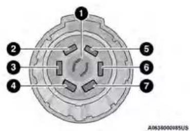
Seven-PinConnector
1 - Backup Lamps
2 - Running Lamps
3 - Left Stop/Turn
4 - Ground
5 - Battery
6 - Right Stop/Turn
7 - Electric Brakes
TOWING TIPS
Before towing, practice turning, stopping, and backing up the trailer in an area located away from heavy traffic.
AutomaticTransmission
Select the DRIVE range when towing. The transmission controls Include a drive strategy to avoid frequent shifting when towing. For Increased engine braking on steep downhill grades, select the LOW range.
CruiseControl—IfEquipped
- Do not use on hilly terrain or with heavy loads.
- When using the Cruise Control, if you experience speed drops greater than 10 mph (16 km/h), disengage until you can get back to cruising speed.
- Use Cruise Control in flat terrain and with light loads to maximize fuel efficiency.
STARTING AND OPERATING
RECREATIONALTOWING(BEHINDMOTORHOME)
TOWING THIS VEHICLE BEHIND ANOTHER VEHICLE
| TowingConditionWheelOFFTheGroundFWDModels | ||
| Flat Tow NONE NOTALLOWED | ||
| Dolly Tow | Front OK | |
| Rear NOTALLOWED | ||
| On Trailer ALL OK | ||
NOTE:
- To avoid inadvertent Electric Park Brake engagement, you must ensure that the A Brake feature is disabled before towing (if rear wheels are on the ground). The Brake feature is enabled or disabled via tomer programmable features page 101.
- When towing your vehicle, always follow state and provincial laws. Contact state cial Highway Safety offices for additional
- If your vehicle is disabled and in need towing service, for further information → page 181.
DONOTflat tow this vehicle. Damage to the will result.
CAUTION!
- DO NOT flat tow this vehicle. Damage t train will result. If this vehicle requires make sure the drive wheels are OFF th
- Ensure that the EPB is released, and r released, while being towed.
- Towing this vehicle in violation of the p listed requirements can cause severe tran damage. Damage from improper towing is ered under the New Vehicle Limited War
RecreationalTowing
Front-Wheel Drive (FWD) Models
Auto P Recreational towing is allowed ONLY if the front vehicle OFF the ground. This may be accomplished to Auto Parkdolly (front wheels off the ground) or vehicle the (oils- four wheels off the ground). If using a tow low this procedure:
applicable Properly secure the dolly to the tow vehicle, and proving the dolly manufacturer's instructions. details 2. Drive the front wheels onto the tow dolly of commercial 3. Apply the parking brake.
- Place the transmission in PARK.
drivetrain Turn the ignition OFF.
- Properly secure the front wheels to the c ing the dolly manufacturer's instructions.
- Turn the ignition to the ON/RUN position, impact the vehicle.
towing,8. Press and hold the brake pedal. e ground.
-
Release the parking brake.
-
Turn the ignition OFF.
sly. Release the brake pedal.
DRIVING TIPS
Acceleration
Rapid acceleration on snow covered, wet, or other slip-powhearsfaces may cause the driving wheels to pull singetically to the right or left. This phenomenon occurs when trait there is a difference in the surface traction und (thedofront folddriving) wheels.
follow-
WARNING!
Rapid acceleration on slippery surfaces is dangerous. Unequal traction can cause sudden pulling of the front wheels. You could lose control of the vehicle a possibly have a collision. Accelerate slowly and carefully whenever there is likely to be poor traction (ice snow, wet, mud, loose sand, etc.).
Traction
When driving on wet or slushy roads, it is possible for wedge of water to build up between the tire and road surface. This is hydroplaning and may cause partial or complete loss of vehicle control and stopping ability. To reduce this possibility, the following precautions should be observed:
- Slow down during rainstorms or when the roads are slushy.
- Slow down if the road has standing water or puddles.
- Replace the tires when tread wear indicators first become visible.
- Keep tires properly inflated.
- Maintain sufficient distance between your vehicle and the vehicle in front of you to avoid a collision a sudden stop.
DRIVING ON SLIPPERY
Information in this section will aid in safe control launches in adverse conditions.
SURFACES
DRIVING THROUGH WATER
Driving through water more than a few inches/centimeters deep will require extra caution to e safety and prevent damage to your vehicle.
WARNING!
- Failure to follow these warnings may result in injuries that are serious or fatal to you, your passengers, and others around you.
Flowing/RisingWater
WARNING!
Do not drive on or across a road or path with flowing and/or rising (as in storm run-off). F water can wear away the road or path's surface cause your vehicle to sink into deeper water. More, flowing and/or rising water can carry your vehicle away swiftly. Failure to follow this warning result in injuries that are serious or fatal to y passengers, and others around you.
CAUTION!
- Always check the depth of the standing water where water before driving through it. Never drive through flowing standing water that is deeper than the bottom of fluid tire rims mounted on the vehicle. - Determine the condition of the road or the path that, is under water and if there are any obstacles, in the way before driving through the standing water. - Do not exceed 5 mph (8 km/h) when driving through standing water. This will minimize wave effects. - Driving through standing water may cause damage to your vehicle's drivetrain components. Always inspect your vehicle's fluids (i.e., engine oil, transmission, axle, etc.) for signs of contamination (i.e., fluid that is milky or foamy in appearance) after driving through standing water. Do not continue to operate the vehicle if any fluid appears contaminated, as this may result in further damage. Such damage is not covered by the New Vehicle Limited Warranty. - Getting water inside your vehicle's engine can cause it to lock up and stall out, and cause serious internal damage to the engine. Such damage is not covered by the New Vehicle Limited Warranty.
ShallowStandingWater
Although your vehicle is capable of driving through low standing water, consider the following Warnings Cautions before doing so.
WARNING!
- Driving through standing water limits your vehi traction capabilities. Do not exceed 5 mph (8 km/h) when driving through standing water. - Driving through standing water limits your vehi braking capabilities, which increases stopping distances. Therefore, after driving through standing water, drive slowly and lightly press on the pedal several times to dry the brakes.
(Continued)
MULTIMEDIA
UCONNECTSYSTEMS
The risk of unauthorized and unlawful access vehicle systems may still exist, even if the
to UCONNECT SETTINGS
For detailed information about your Uconnect 5 with 7-Inch Display or Uconnect 5/5 NAV With 10.1-Inch Dis
play system, refer to your Uconnect Radio Instruction Manual.
NOTE:
Uconnect screen images are for illustration purposes only and may not reflect exact software for your
CYBERSECURITY
Depending on applicability, your vehicle may be able to send or receive information from a wired or wireless network. This information allows systems and features in your vehicle to function properly.
- ONLY insert trusted devices/components into es vehicle. Media of unknown origin could pos vemkin malicious software, and if installed vehicle, it may increase the possibility for systems to be breached.
- As always, if you experience unusual vehicle behavior, take your vehicle to an authorized to immediately.
NOTE:
Your vehicle may be equipped with certain security threats to reduce the risk of unauthorized and unaffordable access to vehicle systems and wireless communications. Vehicle software technology continues to evolve over time and FCA US LLC, working with its suppliers evaluates and takes appropriate steps as needed. As you experience unusual behavior, contact an
authorized dealer immediately, page 228, or refer to your Uconnect Radio Instruction Manual for additional contact information.
Software The econnect system uses a combination of buttons o the touchscreen and buttons on the faceplate located on the center of the instrument panel. These buttons allow you to access and change the Customer Program mable Features. Many features can vary by vehicle.
your buttons on the faceplate are located below and/or simply. Beside the Uconnect system in the center of the instruction your panel. In addition, there is a SCROLL/ENTER control knob located on the right side. Turn the control knob to scroll through menus and change settings. Push the center of the control knob one or more tir machine to select or change a setting.
Your Uconnect system may also have SCREEN OFF and MUTE buttons on the faceplate.
Push the SCREEN OFF button on the faceplate to turn off the Uconnect screen. Push the button again or ta the screen to turn the screen on.
Press the Back Arrow button to exit out of a Menu certain option on the Uconnect system.
^1 Push and hold the Power button on the radio's face-plate for a minimum of 15 seconds to reset the rac
CUSTOMER PROGRAMMABLE FEATURES
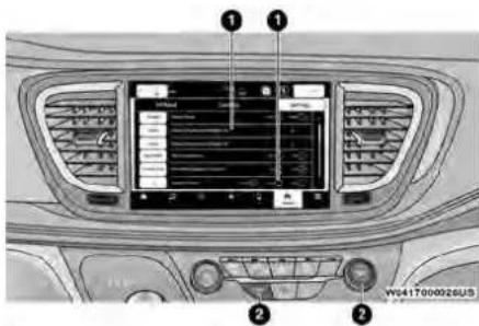
Uconnect5/5NAVWith10.1-InchDisplay
1 — Uconnect Buttons On The Touchscreen 2 — Uconnect Buttons On The Faceplate
NOTE:
- Only one touchscreen area may be selected at a time.
- Depending on the vehicle's options, feature settings may vary.
When making a selection, press the button on the touchscreen to enter the desired menu. Once in the desired menu, press and release the preferred setting option until a check mark appears next to the setting, showing that setting has been selected. Once the setting is complete, press the Vehicle button to exit to the screen. Pressing the Up or Down Arrow button on the right side of the screen will allow you to toggle up or down through the available settings.
ForTheUconnect5With7-inchDisplayandTheUconnect5/5NAVWith10.1-inchDisplay
Press the Vehicle button, then press the Settings tab at the top of the touchscreen. In this menu, the Uconnect system allows you to access all of the available programmable features.
MyProfile
When the My Profile button is pressed on the touchscreen, the system displays options related to the vehicle's profiles.
NOTE:
Depending on the vehicle's options, feature settings may vary.
| SettingNameDescription | |
| Language | This setting will change the language of the Uconnect system and Instrument Cluster Display. The available languages are English, Français, Español, and Italiano. |
| DisplayMode | The setting will adjust the display for the radio to “Auto” or “Manual”. “Manual” allows for more radio display. |
| DisplayBrightnessHeadlightsOn | This setting will allow you to set the brightness when the headlights are on. To access this setting, Display Mode must be set to “Manual”. The “+” setting will increase the brightness; the “-” will decrease the brightness. |
| DisplayBrightnessHeadlightsOff | This setting will allow you to set the brightness when the headlights are off. To access this setting, Display Mode must be set to “Manual”. The “+” setting will increase the brightness; the “-” will decrease the brightness. |
| SetThemeThis setting will allow you to change the theme of the radio. | |
| ThemeMode | This setting will allow you to adjust the brightness of your theme. Setting options are “Light”, “Dark” and “Auto”. Select to show themes in Light or Dark mode. “Auto” changes the theme with the headlights. |
| Units | This setting changes the “Speed” (MPH or km/h), “Distance” (ml or km), “Fuel Consumption” (MPG L/100 km, or km/L), “Pressure” (psi, kPa, or bar), “Temperature” (°C or °F), and “Current Consum [UK], L/100 km, or km/L) units of measurement independently. |
| TouchscreenBeepThis setting will allow you | to turn the touchscreen beep on or off. |
| Show Main Category Bar Labels | This setting will allow the main category bar labels to be shown on or off. |
| Navigation Next Turn Displayed in Cluster | This setting will display navigation prompts in the Instrument Cluster Display. |
| Phone Pop-Ups Displayed In Cluster | This setting will display smartphone notifications and messages in the Instrument Cluster Display. |
| System Text Size | This setting will allow you to change the text on the radio to “Standard”, “Large”, and “Taller”. |
| TimeFormat | This setting will allow you to set the time format (AM/PM). Sync Time With GPS must be “Off” for this setting to be avail-able. The “12 hrs” setting will set the time to a 12-hour format. The “24 hrs” setting will set the time to a 24-hour format. |
| Voice Options | This setting will allow you to change the voice options for the radio to “Male” or “Female”. |
customizat
[US], MP
ption" (M
| SettingNameDescription | |
| Wake Up Word | This setting will allow you to turn the voice recognition “Wake Up” word on or off. |
| Voice Barge-in | This setting will allow you to turn the voice recognition barge-in feature on or off. |
| ShowCommandListThis setting will allow the | Command List to be shown on or off. |
| KeyOffPowerDelay | This setting will keep certain electrical features running after the engine is turned off. When any door is opened, the electronics will deactivate. The available settings are “0 sec”, “45 sec”, “5 min”, and “10 min”. |
| Radio Off With Door | This setting will turn the radio off when the driver or passenger door is opened. The available settings are “On” and “Off”. |
| App Drawer Favoriting Popups | This setting will allow you to favorite app drawer pop-ups with “On” and “Off” options. |
| App Drawer Unfavoritings Popups | This setting will allow you to unfavorable app drawer pop-ups with “On” and “Off” options. |
| New Text Message Popups | This setting will allow you to have pop-up notifications for new text messages. This setting options are “On” and “Off”. |
| Missed Calls Message | This setting will allow you to have pop-up notifications for missed calls. This setting options are “On” and “Off”. |
| Navigation Popups | This setting will allow you to have pop-up notifications for Navigation. This setting options are “On” and “Off”. |
| Navigation Settings | This setting will allow you to customize the settings within Navigation Mode. |
| Auto-OnDriverHeatedSeat&SteeringWheel | This setting will activate the vehicle’s comfort systems and heated seats or heated steering wheel remote started or ignition is started. The “Off” setting will not activate the comfort systems. The “Remote Start” setting will only activate the comfort systems when using Remote Start. The “All Start” setting will activate the comfort systems whenever the vehicle is started. |
| AudioSettingsThis setting will take you to | the audio settings for the vehicle profiles. |
| Reset App Drawer to Default Order | This setting will reset the app drawer to its factory default layout. |
| Restore Settings to Default | This setting will return all the previously changed settings to their factory defaults. |
| More Profile Options | This setting will give access to more profile options. |
when the
Display
After pressing the Display button on the touchscreen, the following settings will be available:
NOTE:
Depending on the vehicle's options, feature settings may vary.
| SettingNameDescription | |
| Language | This setting will change the language of the Uconnect system and Instrument Cluster Display. The available languages are English, Français, Español, and Italiano. |
| Display Mode | This setting will allow you to set the brightness manually or have the system set it automatically. The “Auto” setting has the system automatically adjust the display brightness. The “Manual” setting will allow the user to adjust the brightness of the display. |
| DisplayBrightnessWithHeadlights ON/Brightness | This setting will allow you to set the brightness when the headlights are on. To access this setting, Display Mode must be set to “Manual”. The “+” setting will increase the brightness; the “-” will decrease the brightness. |
| DisplayBrightnessWithHeadlights OFF/Brightness | This setting will allow you to set the brightness when the headlights are off. To access this setting, Display Mode must be set to “Manual”. The “+” setting will increase the brightness; the “-” will decrease the brightness. |
| SetThemeThis setting will allow you to change the theme of the radio. | |
| Theme Mode | This setting will allow you to adjust the brightness of your theme. Setting options are “Light”, “Dark” and “Auto”. Select to show themes in Light or Dark mode. “Auto” changes the theme with the headlights. |
| Units | This setting changes the “Speed” (MPH or km/h), “Distance” (ml or km), “Fuel Consumption” (MPG [US], MPG [UK], L/100 km, or km/L), “Pressure” (psi, kPa, or bar), “Temperature” (°C or °F), and “Current Consum [UK], L/100 km, or km/L) units of measurement independently. |
| TouchscreenBeepThis setting will allow you to turn the touchscreen beep on or off. | |
| Show Main Category Bar Labels | This setting will allow the main category bar labels to be shown on or off. |
| ControlScreenTimeout | This setting allows you to set the Control Screen to turn off automatically after five seconds or stay open until manually closed. |
| Navigation Next Turn Displayed in Cluster | This setting will display navigation prompts in the Instrument Cluster Display. |
| Phone Pop-Ups Displayed In Cluster | This setting will display smartphone notifications and messages in the Instrument Cluster Display. |
| Ready To Drive Pop-Ups | This setting will enable the Ready To Drive Pop-Ups in the Instrument Cluster Display. |
Safety&DrivingAssistance
After pressing the Safety & Driving Assistance button on the touchscreen, the following settings will be available:
NOTE:
Depending on the vehicle's options, feature settings may vary.
| SettingNameDescription | |
| ForwardCollisionWarningSensitivity–LocatedInAutomaticEmergencyBrakingSubmenu | This setting will change the distance at which the Forward Collision Warning (FCW) alert sounds. The “Medium” setting will have the FCW system signal when an object is in view, and the possibility of a collision is detected. The “Near” setting will have the FCW system signal when the object is closer to the vehicle. The “Far” setting will have when an object is at a far distance from the vehicle. |
| ForwardCollisionWarning–LocatedInAutomatic EmergencyBrakingSubmenu | This setting will turn the Forward Collision Warning system on or off. The “Off” setting will deactivate the FCW system. The “Warning Only” setting will provide only an audible chime when a collision is detected. The “Warning + Active Braking” setting will provide an audible chime and apply some brake pressure when a collision is detected. |
| PedestrianEmergencyBraking–LocatedInAutomaticEmergencyBrakingSubmenu | This setting will turn the Pedestrian Emergency Braking system “Off” or to “Warning & Active Braking” |
| ParkSense | This setting will change the type of ParkSense alert when a close object is detected. The “Sound Only” setting will provide an audible chime when an object is detected. The “Sound and Display” setting will provide both visual display when an object is detected. |
| Rear ParkSense Volume | This setting adjusts the volume of the Rear ParkSense system. The available settings are “Low”, “Medium”, and “High”. |
| Rear ParkSense Braking Assist | This setting will turn the Rear ParkSense Braking Assist on or off. |
| SlidingDoorAlertThis setting will turn the Sliding Door Alert on and off. | |
| Blind Spot Alert | This setting will change the type of alert provided when an object is detected in a vehicle’s blind spot. The “Off” setting will turn off Blind Spot Alert. The “Lights” setting will activate the Blind Spot Alert lights on the outside mirrors. The “Lights & Chime” setting will activate both the lights on the outside mirrors and an audible chime. |
| HillStartAssistThis setting will turn the Hill | Start Assist system on or off. |
| Rear Seat Alert | When this setting is turned on and the rear doors are opened while the engine is running, or if the engine is turned on within 10 minutes of the door opening, a message will appear to check the rear seat when the |
the FCv
5
ing".
an audible
vehicle
Clock&Date
After pressing the Clock & Date button on the touchscreen, the following settings will be available:
NOTE:
Depending on the vehicle's options, feature settings may vary.
| SettingNameDescription | |
| Sync Time With GPS | This setting will sync the time to the GPS receiver in the system. The system will control the time via the GPS location. |
| SetTimeThis setting will allow you to manually set the time of your clock. | |
| Time Format | This setting will allow you to set the time format (AM/PM). Sync Time With GPS must be off for this setting to be available. The “12 hrs” setting will set the time to a 12-hour format. The “24 hrs” setting will set the time to a 12-hour format. |
| SetDateThis setting will allow you to set the date by day, month, and year (DD/MM/YY). | |
| Set Time Hours | This setting will allow you to set the hours. Sync Time With GPS must be off for this setting to be available. The “+” setting will increase the hours. The “-” setting will decrease the hours. |
| Set Time Minutes | This setting will allow you to set the minutes. Sync Time With GPS must be off for this setting to be available. The “+” setting will increase the minutes. The “-” setting will decrease the minutes. |
| ShowTimeinStatusBarThis setting will place the time in the radio's status bar. | |
time to a
Phone/Bluetooth®
When the Phone/Bluetooth® button is pressed on the touchscreen, the system displays the options related to Bluetooth® connectivity from an external audio device or smartphone. The list of paired audio devices or smartphones can be accessed from this menu.
NOTE:
Depending on the vehicle's options, feature settings may vary.
| SettingNameDescription | |
| DeviceManagerThis setting will open the Device Manager main screen. | |
| Do Not Disturb | This setting will open the Do Not Disturb Settings menu. The settings are “Auto Reply” (both, text, call), “Auto Reply Message” (custom, default), and “Custom Auto Reply Message” (create message). |
| Do Not Disturb All | This setting will open the “Do Not Disturb All” Settings menu. The available options are “On” and “Off”. |
| Enable Two Active Phones | This setting will enable or disable two active phones with the vehicle. The setting options are “On” and “Off”. |
| Phone Pop-Ups Displayed In Cluster | This setting will activate phone message pop-ups in the Instrument Cluster Display. |
Voice—IfEquipped
After pressing the Voice button on the touchscreen, the following settings will be available:
NOTE:
Depending on the vehicle's options, feature settings may vary.
| SettingNameDescription | |
| Voice Options | This setting will allow you to change the voice options for the radio to “Male” or “Female”. |
| Wake Up Word | This setting will allow you to turn the voice recognition “Wake Up” word on or off. |
| Voice Barge-In | This setting will allow you to turn the voice recognition barge-in feature on or off. |
| Show Command List | This setting will allow you to turn the Command List on or off. The “Always” setting will always show the Command List. The “With Help” setting will show the Command List and provide a brief description of what the com setting will turn the Command List off. |
Navigation—IfEquipped
When the Navigation button is pressed on the touchscreen, the system displays options related to the vehicle's built-in Navigation system. These settings can change which icons display on the map, how "time to arrival" is calculated, and route types. For more information on Navigation and settings, refer to your Uconnect Radio Instruction Manual.
NOTE:
Depending on the vehicle's options, feature settings may vary.
Camera
When the Camera button is pressed on the touchscreen, the system displays the options related to the vehicle's camera features.
NOTE:
Depending on the vehicle's options, feature settings may vary.
| SettingNameDescription | |
| ParkView Backup Camera Delay | This setting will add a timed delay to the ParkView Backup Camera when shifting out of REVERSE. |
| ParkView Backup Camera Active Guidelines | This setting will turn the ParkView Backup Camera Active Guidelines on or off. |
| ParkView Backup Camera Fixed Guidelines | This setting will turn the ParkView Backup Camera Fixed Guidelines on or off. |
Mirrors&Wipers
When the Mirrors & Wipers button is pressed on the touchscreen, the system displays the options related to the vehicle's mirrors and wipers.
NOTE:
Depending on the vehicle's options, feature settings may vary.
| SettingNameDescription | |
| RainSensingAutoWipersThis setting will turn | the Rain Sensing Auto Wipers on or off. |
| Headlights With Wipers | This setting will turn the headlights on when the wipers are activated. |
Lights
When the Lights button is pressed on the touchscreen, the system displays the options related to the vehicle's exterior and interior lights.
NOTE:
- When the "Daytime Running Lights" feature is selected, the daytime running lights can be turned on or off. This feature is only allowed by law in the country of the vehicle purchase.
- Depending on the vehicle's options, feature settings may vary.
| SettingNameDescription | |
| Headlight Off Delay | This setting will allow you to set the amount of time it takes for the headlights to shut off after the vehicle is turned off. The available settings are “0 sec”, “30 sec”, “60 sec”, and “90 sec”. |
| Headlight Illumination On Approach | This setting will allow you to set the amount of time it takes for the headlights to shut off after the vehicle is unlocked. The available settings are “0 sec”, “30 sec”, “60 sec”, and “90 sec”. |
| Headlights with Wipers | This setting will turn the headlights on when the wipers are activated. |
| Daytime Running Lights | This setting will allow you to turn the Daytime Running Lights on or off. |
| Flash Lights With Lock | This setting will allow you to turn the flashing of the lights when the Lock button is pushed on the key fob on or off. |
| AutoDimHighBeamsThis setting will allow you to turn the Auto Dim High Beams on or off. | |
| Flash Lights With Sliding Door | This setting will flash the lights when the sliding door reverses. The available options are “On” and “Off”. |
Brakes
After pressing the Brakes button on the touchscreen, the following settings will be available:
NOTE:
Depending on the vehicle's options, feature settings may vary.
| SettingNameDescription | |
| AutoParkBrakeThis setting will turn the Auto Park Brake on or off. | |
| BrakeServiceThis setting will allow you to retract the brakes for servicing. | |
Doors&Locks
After pressing the Doors & Locks button on the touchscreen, the following settings will be available:
| SettingNameDescription | |
| Auto Unlock On Exit | This setting will unlock the doors when any of the doors are opened from the inside. |
| Flash Lights With Lock | This setting will allow you to turn the flashing of the lights when the Lock button is pushed on the key fob on or off. |
| Sound Horn With Lock | This setting will sound the horn when the Lock button is pushed on the key fob. The “Off” setting will not sound the horn when the Lock button is pushed. The “1st Press” setting will sound the horn when the Lock but “2nd Press” setting will sound the horn when the Lock button is pushed twice. |
| Sound Horn With Remote Start | This setting will sound the horn when the remote start is activated from the key fob. |
| RemoteDoorUnlock,DoorLock/1stPressOfKey FobUnlocks | This setting will change how many pushes of the Unlock button on the key fob are needed to “Driver Door” setting will only unlock the driver door on the first push on the Unlock button. The “All Doors” setting will unlock all doors with only one push of the Unlock button. |
| Passive Entry | This setting will allow you to turn the Passive Entry feature (Keyless Enter ‘n GoTM) on or off. |
| Personal Settings Linked To Key Fob | This setting will recall preset radio stations and driver seat position that have been linked to the key fob. |
tton is pi
unlock all
| SettingNameDescription | |
| PowerLiftgateAlert | This setting will chime an audible alert when the power liftgate is raising or lowering. Selectable "Off". |
| SlidingDoorAlert | This setting will chime an audible alert when the sliding door reverses or sense an obstacle. Selectable options are "On" and "Off". |
| Flash Lights with Sliding Door | This setting will flash the lights when the sliding door is opening. Selectable options are "On" and "Off". |
options an
Seats&Comfort
When the Seats & Comfort button is pressed on the touchscreen, the system displays the option related to the vehicle's comfort systems when remote start has been activated or the vehicle has been started.
NOTE:
Depending on the vehicle's options, feature settings may vary.
| SettingNameDescription | |
| Auto-OnDriverHeated/VentilatedSeat&Heated SteeringWheelWithVehicleStart | This setting will activate the vehicle's comfort systems and heated seats or heated steering wheel remote started or ignition is started. The “Off” setting will not activate the comfort systems. The “Remote Start” setting will only activate the comfort systems when using Remote Start. The “All Start” setting will activate the comfort systems whenever the vehicle is started. |
5
when the
KeyOffOptions
When the Key Off Options button is pressed on the touchscreen, the system displays the options related to vehicle shutoff. These settings will only activate when the ignition is set to OFF.
NOTE:
Depending on the vehicle's options, feature settings may vary.
| SettingNameDescription | |
| Key Off Power Delay | This setting will keep certain electrical features running after the engine is turned off. When any door is opened, the electronics will deactivate. The available settings are “0 sec”, “45 sec”, “5 min”, and “10 min”. |
| Headlight Off Delay | This setting will allow you to set the amount of time the headlights remain on after the vehicle has been turned off. The “+” will increase the amount of time. The “-” will decrease the amount of time. |
| Radio Off With Door | This setting will turn the radio off when the driver or passenger door is opened. The available settings are “On” and “Off”. |
Audio
When the Audio button is pressed on the touchscreen, the system displays options related to the vehicle's sound system. These settings can change the audio location within the vehicle, adjust the bass or treble levels, and auto-play settings from an audio device or smartphone.
NOTE:
Depending on the vehicle's options, feature settings may vary.
| SettingNameDescription | |
| Balance/Fade | This setting will adjust audio levels from specific speakers in the front/back and left/right of the vehicle. The Speaker icon can be moved to set audio location. |
| EqualizerThis setting will adjust the “Bass”, “Mid”, and “Treble” ranges of the audio. | |
| Speed Adjusted Volume | This setting will adjust audio volume as speeds increase. At a higher setting, the volume will increase more as the vehicle speeds up. The available settings are “Off”, “1”, “2”, and “3”. |
| SurroundSoundThis setting will turn the Surround Sound system on or off. | |
| AUX Volume Offset | This setting will tune the audio levels from a device connected through the AUX port. The available settings are "+" and "-". |
| AutoPlayThis setting will automatically begin | playing audio from a connected device. |
| Auto On Radio | This setting will automatically turn on when the vehicle is in ON/RUN or will recall whether it was on or off at last ignition OFF. The selectable options are "On", "Off", and "Recall Last". |
| Volume Adjustment | This setting allows you to adjust the volume levels for features such as Media, Phone, Navigation, and Voice Recognition. |
Notifications
When the Notifications button is pressed on the touchscreen, the system displays the options related to Notifications for the system.
NOTE:
Depending on the vehicle's options, feature settings may vary.
| SettingNameDescription | |
| AppDrawerFavoritingPopupsThis setting turns | the App Favorited pop-up on or off. |
| AppDrawerUnfavoritingPopupsThis setting turns | the App Unfavorited pop-up on or off. |
| New Text Message Popups | This setting turns receiving/storing a pop-up for new text messages of any connected phone on or off. |
| Missed Calls Message | This setting turns receiving/storing a pop-up for missed calls of any connected phone on or off. |
| NavigationPopupsThis setting turns navigation | pop-ups on or off. |
| SiriusXM® Travel Link Weather Alerts | The setting turns receiving notifications for SiriusXM® Travel Link Weather Alerts on or off. |
SiriusXM®Setup
When the SiriusXM® Setup button is pressed on the touchscreen, the system displays options related to SiriusXM® satellite radio. These settings can be used to skip specific radio channels and restart favorite songs from the beginning.
NOTE:
- A subscription to SiriusXM® satellite radio is required for these settings to be functional.
- Depending on the vehicle's options, feature settings may vary.
| SettingNameDescription | |
| SiriusXM® Account, Profiles & Settings | This setting will allow you to view your SiriusXM® account information, profiles linked to the system, and the various settings you have saved and stored to those profiles. |
| Block Explicit | This setting will allow you to block explicit content by turning it on or off. |
SoftwareUpdates
When the Software Updates button is pressed on the touchscreen, the system will display information on updating the Uconnect system's software.
NOTE:
Depending on the vehicle's options, feature settings may vary.
| SettingNameDescription | |
| Software Downloads over Wi-Fi | This setting will allow software updates to happen over Wi-Fi. Selectable options for the setting are “On” and “Off”. |
SystemInformation
When the System Information button is pressed on the touchscreen, the system displays the radio system information.
NOTE:
Depending on the vehicle's options, feature settings may vary.
| SettingNameDescription | |
| VersionInformation | When this feature is selected, a Version Information screen will appear, displaying information about the version of your radio. |
| License Information | When this feature is selected, a License Information screen will appear, displaying the licensing information of your radio. |
Reset
When the Reset button is pressed on the touchscreen, the system displays the options related to resetting the Uconnect system back to its default settings. These settings can clear personal data and reset selected settings from other menus.
NOTE:
Depending on the vehicle's options, feature settings may vary.
| SettingNameDescription | |
| Notifications Sounds | Turn this setting on or off to hear notification sounds throughout your system. |
| RestartRadioThis setting will restart the radio. | |
| Reset App Drawer to Default Order | This setting will reset the app drawer to its factory default layout. |
| Restore Settings to Default | This setting will return all the previously changed settings to their factory defaults. |
| Clear Personal Data | This setting will display a pop-up that gives you the option to clear all personal data from the system, including Bluetooth® devices and presets. |
| Reset Wi-Fi Password for Projection | This setting will reset your Wi-Fi password for projection. |
| Factory Reset | This setting will factory reset the radio. It may cause the radio to restart multiple times and the backup camera, radio, SOS, and several driving assistance features will not be available. Once the system resets, you will need to turn the vehicle off then back on to complete the process. |
STEERINGWHEELAUDIOCONTROLS
The remote sound system controls are located or rear surface of the steering wheel at the three o'clock positions.
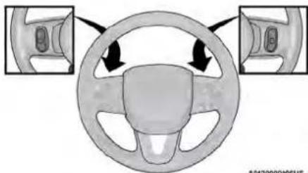
natural_image
Diagram of a car steering wheel with two side-view diagrams showing front and rear views (no text or labels)SteeringWheelAudioControls
A042000096US
RADIO OPERATION
Pushing the top of the switch will seek up available station, and pushing the bottom of will seek down for the next available station.
The button located in the center of the left will tune to the next preset station that you grammed in the radio preset button.
MEDIA MODE
Pushing the top of the switch once goes to track on the selected media (AUX/USB/Bluetooth). Pushing the bottom of the switch once goes beginning of the current track, or to the begin the previous track if it is within eight second current track begins to play.
RADIOOPERATIONANDMOBILEPHONES
REGULATORY AND SAFETY INFORMATION
e switch US/CANADA
Exposure to Radio Frequency Radiation
The radiated output power of the internal wireless radiis far below the FCC and IC radio frequency exposure limits. Nevertheless, the wireless radio will be used in such a manner that the radio is 8 inches (20 cm) further from the human body.
the next The internal wireless radio operates within guidelines found in radio frequency safety standards and recommendations, which reflect the consensus of the scientific community. after the
The radio manufacturer believes the internal wireless radio is safe for use by consumers. The level of energy emitted is far less than the electromagnetic energy emitted by wireless devices such as mobile phones. However, the use of wireless radios may be restricted
The right-hand control is a rocker-type switch with under certain conditions, the mobile phone being some situations or environments, such as aboard air-push button in the center and controls the volume of vehicle can cause erratic or noisy performance. If you are unsure of restrictions, you are enc mode of the sound system. Pushing the top of from your radio. This condition may be lessened aged to ask for authorization before turning on the rocker switch increases the volume, and pushing eliminated by repositioning the mobile phone with less radio page 231.
bottom of the rocker switch decreases the volumewhicle. This condition is not harmful to the radio. If Pushing the right-hand control's center button makes your radio performance does not satisfactorily improve the radio switch between the various modes available from repositioning the mobile phone, it is recommended that the volume be turned down or off during (AM/FM/SXM or Media, etc.)
The left-hand control is a rocker-type switch with a push button in the center. The function of the left-hand con-
trol is different depending on which mode you are in.
The following describes the left-hand control operation in each mode:
SAFETY
SAFETYFEATURES
The ABS provides increased vehicle stability and performance under most braking conditions. The system automatically prevents wheel lock and enhance vehicle control during braking.
The ABS performs a self-check cycle to ensure ABS is working properly each time the vehicle I and driven. During this self-check, you may hear clicking sound as well as some related motor m. The ABS is activated during braking when the s detects one or more wheels are beginning to lo conditions such as ice, snow, gravel, bumps, rail tracks, loose debris, or panic stops may increase likelihood of ABS activation(s).
You also may experience the following normal characteristics when the ABS activates:
- ABS motor noise or clicking sounds (you may tinue to hear for a short time after the sto
- Brake pedal pulsations
- A slight drop of the brake pedal at the end stop
The ABS is designed to function with the Original segment Manufacturer (OEM) tires. Modification may result in degraded ABS performance.
WARNING!
- The ABS contains sophisticated electronic equipment that may be susceptible to interfered by an overexpressing system caused by improperly installed or high output systems transmitting equipment. This interference can cause possible loss of anti-lock braking capacity. Installation of such equipment should be performed by qualified professionals.
- Ramping of the Anti-Lock Brakes will dimming a tightness and may lead to a collision. Oises makes the stopping distance longer. Just be firmly on your brake pedal when you need down or stop.
The ABS cannot prevent the natural laws from acting on the vehicle, nor can it in braking or steering efficiency beyond that by the condition of the vehicle brakes and the traction afforded. - The ABS cannot prevent collisions, including (p) resulting from excessive speed in turns, for another vehicle too closely, or hydroplaning.
- The capabilities of an ABS equipped vehicle of the never be exploited in a reckless or dangerer that could jeopardize the user's safety and safety of others.
Anti-LockBrakeSystem(ABS)Warning Light
The yellow ABS Warning Light will turn on when the tion is placed in the ON/RUN mode and may stay o put radio as long as four seconds.
ability. the ABS Warning Light remains on or comes on which per-driving, it indicates that the anti-lock portion of the bral system is not functioning and that service is required. However, the conventional brake system will continue to finish their operate normally if the ABS Warning Light is on.
press if the ABS Warning Light is on, the brake system should be serviced as soon as possible to restore the benefit of Anti-Lock Brakes. If the ABS Warning Light does not come on when the ignition is placed in the ON/RUN of physics mode, have the light repaired as soon as po
REAR SEAT REMINDER ALERT tires or (RSRA)
6
the RSRA alerts of the possible presence of an object, pa widinger, or pet in the rear seats through a visual and auditory notification. When the system is activated, it displays the message "Check Rear Seat" on the instru- ument cluster display and sounds an auditory alert upon or the driver placing the ignition in the OFF position to the vehicle. The system will activate automatically if a rear door is opened within 10 minutes of the ignition being placed in the ON/RUN position. RSRA should be used as a reminder to check the rear seats; it does directly detect objects, passengers, or pets and is only activated when the previous conditions are met.
To enable or disable RSRA page 100.
WARNING!
- Before exiting a vehicle, always come to plete stop, then shift the automatic trans into PARK and apply the parking brake.
- Always make sure the keyless ignition node the OFF position, key fob is removed from vehicle and vehicle is locked.
- Never leave children alone in a vehicle, access to an unlocked vehicle. Leaving of a vehicle unattended is dangerous for a reasons. A child or others could be seriously fatally injured. Children should be warned to touch the parking brake, brake pedal or selector.
- Do not leave children or animals inside pa vehicles in hot weather. Interior heat buildu cause serious injury or death.
Your vehicle is equipped with an advanced Electric Brake Control (EBC) system. This system includes Lock Brake System (ABS), Brake Assist System (ECR), Electronic Brake Force Distribution (EBD), Electronic Roll Mitigation (ERM), Electronic Stability Control (ICM), Hill Start Assist (HSA), and Traction Control System (TCS). These systems work together to enhance both vehicle stability and control in various driving conditions.
Your vehicle may also be equipped with Dyn ing Torque (DST), Ready Alert Braking (RAB), Support (RBS) and Trailer Sway Control (TSC).
BrakeAssistSystem(BAS)
The BAS is designed to optimize the vehicle's capability during emergency braking maneuvers. This system detects an emergency braking situation, sensing the rate and amount of brake application, then applies optimum pressure to the brakes. The help reduce braking distances. The BAS compares the Anti-Lock Brake System (ABS). Applying the very quickly results in the best BAS assistance for which they receive the benefit of the system, you must be in numerous braking pressure during the stopping period (do not "pump" the brakes). Do not reduce pressure unless braking is no longer desired. The brake pedal is released, the BAS is deactivating the gear.
WARNING!
The Brake Assist System (BAS) cannot prevent natural laws of physics from acting on the can it increase the traction afforded by pre road conditions. BAS cannot prevent collisions including those resulting from excessive speed turns, driving on very slippery surfaces, or turning. The capabilities of a BAS-equipped vehicle never be exploited in a reckless or dangerous anti-er, which could jeopardize the user's safety safety of others.
BrakeSystemWarningLight
The red Brake System Warning Light will turn the ignition is placed in the ON/RUN mode a stay on for as long as four seconds.
If Brake Brake System Warning Light remains on or comes on while driving, it indicates that the brake system is not functioning properly and that immediate service is
required. If the Brake System Warning Light does not come on when the ignition is placed in the ON/RUN braking mode, have the light repaired as soon as possible.
^37 DynamicSteeringTorque(DST)
NST is a feature of the ESC and Electric Power Stee (EFS) modules that provides torque at the steering wheel for certain driving conditions in which the ESC module is detecting vehicle instability. The torque that the steering wheel receives is only meant to help the drive realize optimal steering behavior in order to reach maintain vehicle stability. The only notification the driver receives that the feature is active is the torque applied to the steering wheel.
NOTE:
The DST feature is only meant to help the driver rea t the correct course of action through small torques on the steering wheel, which means the effectiveness of vehicle, nor the DST feature is highly dependent on the driver's sailingitivity and overall reaction to the applied torque. It is very important to realize that this feature will not ster in the vehicle, meaning the driver is still responsible for hydroplan- e steering the vehicle.
s ElectronicBrakeForceDistribution or the (EBD)
The EBD function manages the distribution of the braking torque between the front and rear axles by limiting braking pressure to the rear axle. This is done to prevent reversibility of the rear wheels to avoid vehicle instability, and to prevent the rear axle from entering the A Lock Brake System (ABS) before the front axle.
ElectronicRollMitigation(ERM)
ERM anticipates the potential for wheel lift by rising the driver's steering wheel input and the sp the vehicle. When ERM determines that the rate change of the steering wheel angle and vehicle's are sufficient to potentially cause wheel lift, it is applies the appropriate brake and may also reduce engine power to lessen the chance that wheel occur. ERM can only reduce the chance of wheel occurring during severe or evasive driving maneuver cannot prevent wheel lift due to other factors, road conditions, leaving the roadway, striking object other vehicles.
WARNING!
Many factors, such as vehicle loading, road tions and driving conditions, influence the cl that wheel lift or rollover may occur. ERM a vent all wheel lift or rollovers, especially the involve leaving the roadway or striking object other vehicles. The capabilities of an ERM-e vehicle must never be exploited in a reckless gerous manner which could jeopardize the u safety or the safety of others.
ElectronicStabilityControl(ESC)
ESC enhances directional control and stability of vehicle under various driving conditions. ESC corre for oversteering or understeering of the vehicle to applying the brake of the appropriate wheel(s) to in counteracting these conditions. Engine power m also be reduced to help the vehicle maintain the desired path.
- Oversteer — when the vehicle is turning more appropriate for the steering wheel position.
• Understeer — when the vehicle is turning less appropriate for the steering wheel position. ESCpeases sensors in the vehicle to determine the vehicle path intended by the driver and compare the actual path of the vehicle. When the actual distances will not match the intended path, ESC applies a takeoff of the appropriate wheel to assist in courings; the oversteer or understeer condition.
The ESC Activation/Malfunction Indicator Light locati its the instrument cluster will start to flash as the ESC system becomes active. The ESC Activat Malfunction Indicator Light also flashes when the active. If the ESC Activation/Malfunction Indicator I begins to flash during acceleration, ease up on accelerator and apply as little throttle as possible sure to adapt your speed and driving to the pr road conditions.
WARNING!
of Electronic Stability Control (ESC) cannot prevent the natural laws of physics from acting on vehicle, nor can it increase the traction at prevailing road conditions. ESC cannot prevent accidents, including those resulting from exc speed in turns, driving on very slippery su hydroplaning. ESC also cannot prevent accident resulting from loss of vehicle control due to appropriate driver input for the conditions. On safe, attentive, and skillful driver can prevent assist dents. The capabilities of an ESC equipped may must never be exploited in a reckless or manner which could jeopardize the user's safety of others.
| than | WARNING! |
| the | vehicle modifications, or failure to properlytain your vehicle, may change the handlingteristics of your vehicle, and may negatively the performance of the ESC system. Changthe steering system, suspension, braking syrlire type and size or wheel size may adffect ESC performance. Improperly inflatedunevenly worn tires may also degrade ESCmance. Any vehicle modification or poor vemaintenance that reduces the effectiveness ESCasystem can increase the risk of losson/control, vehicle rollover, personal injury andTCS is |
ESCOperatingModes
Depending upon model and mode of operation, the ES evailing system may have multiple operating modes.
ESCON
This is the normal operating mode for the ESC. When ever the vehicle is started, the ESC system will be i this mode. This mode should be used for most driving conditions. Alternate ESC modes should only be used by specific reasons as noted in the following paragraphs.
ve PartialOff es. or
This mode may be useful if the vehicle becomes stuck. That mode may modify TCS and ESC thresholds for a avation, which allows for more wheel spin than normally allowed
Hole enter the "Partial Off" mode, momentarily push the ESC OFF button and the ESC OFF Indicator Light will illuminate. To turn the ESC on again, momentarily push the ESC OFF button and the ESC OFF Indicator Light turn off.
(Continued)
NOTE:
When driving with snow chains, or when starting
deep snow, sand, or gravel, it may be desirable
more wheel spin. This can be accomplished by
tarily pushing the ESC OFF button to enter pa
"Partial Off" mode. Once the situation requiring
Off" mode is overcome, turn ESC back on by
lly pushing the ESC OFF button. This may be
the vehicle is in motion.
WARNING!
- When in "Partial Off" mode, the TCS function
ESC (except for the limited slip feature desc
the TCS section) has been disabled and the
Indicator Light will be illuminated. When in
Off" mode, the engine power reduction feature
TCS is disabled, and the enhanced vehicle
offered by the ESC system is reduced. - Trailer Sway Control (TSC) is disabled when
ESC system is in the "Partial Off" mode.
The ESC Activation/Malfunction Indicator Light star the following conditions must be met in order for HS.
flash jns soon as the tires lose traction and the 60vatsys-
etern becomes active. The ESC Activation/Malfunction The feature must be enabled.
Indicator Light also flashes when TCS is active. If the vehicle must be stopped
EISC_{mode} Activation/Malfunction Indicator Light begins to
Partial during acceleration, ease up on the accelerator. The parking brake must be on.
morherally as little throttle as possible. Be sure • toheadpiver door must be closed.
doner waned and driving to the prevailing road • The vehicle must be on a suffi
conditions.

The ESC OFF Indicator Light indicates
the Electronic Stability Control (ESC) is
reduced mode.
ned in
NOTE: ESC OFF
"Partial The ESC Activation/Malfunction Indicator Light and
re of the ESC OFF Indicator Light come on momentari
stability each time the ignition is placed in the ON/RUN
y each time the ignition is placed in the city, position.
the Each time the ignition is placed in the ON/
Each time the ignition is placed in the CIV, tion the ESC system will be on even if it
tion, the LEC system will be on even if it off previously.
• The ESC system will make buzzing or clicking
sounds when it is active. This is normal; the
will stop when ESC becomes inactive following
_maneuver that caused the ESC activation.
le on L/DUN
y/RUN
HillStartAssist(HSA)
Light HSA is designed to mitigate roll back from a
a trial designed to navigate off each from a stop, while on an incline. If the driver release
to this while on an incline. If the driver release while stopped on an incline. USA will continue
nd with the stopped on all incline, HSA will continue
s) that brake pressure for a short period. If the
an not apply the throttle before this time expires,
tem will release brake pressure and the vehicle
down the hill as normal.
- The vehicle must be on a sufficient grade.
- The gear selection must match vehicle uphill direc-
hat tion (i.e., vehicle facing uphill is in forward gear;
in vehicle backing uphill is in REVERSE (R) gear).
• HSA will work in REVERSE gear and all forward
gears. The system will not activate if the transmis-
sion is in PARK (P) or NEUTRAL (N).
| tarilyRUN | WARNING! |
| There may be situations where the Hill Sta(HSA) will not activate and slight rolling maRUN post-such as on minor hills or with a loadedwas turnedwhile pulling a trailer. HSA is not a substractive driving involvement. It is always theresponsibility to be attentive to distance tovebules is people, and objects, and most impbatke operation to ensure safe operation ofvehicle under all road conditions. Your compattention is always required while driving tosafe control of your vehicle. Failure to followarnings can result in a collision or seriousinjurycomplete | |
the brake
to hold DisablingAndEnablingHSA
driver does
This feature can be turned on or turned off. To chair
the will current setting, proceed as followage 100.
HSA will also provide assistance to mitigate while towing a trailer.
WARNING!
- If you use a trailer brake controller with the trailer brakes may be activated and devated with the brake switch. If so, there enough brake pressure to hold both the v and the trailer on a hill when the brake released. In order to avoid rolling down and while resuming acceleration, manually activate trailer brake or apply more vehicle brake prior to releasing the brake pedal.
- HSA is not a parking brake. Always applying brake fully when exiting your vehicle, certain to place the transmission in PARK.
- Failure to follow these warnings can result in vision or serious personal injury.
TractionControlSystem(TCS)
roll TheckTCS monitors the amount of wheel spin of each of
the driven wheels. If wheel spin is detected, the may apply brake pressure to the spinning wheel(s) and/or reduce vehicle power to provide enhanced
acceleration and stability. A feature of the TCS, your trailer Limited Differential (BLD) functions similarly to a deaplip differential and controls the wheel spin across may not be driven axle. If one wheel on a driven axle is faster than the other, the system will apply the podel is spinning wheel. This will allow more vehicle
an incline to be applied to the wheel that is not spinning. BLD remain enabled even if TCS and the Electronic Stability pressure Control (ESC) are in reduced modes.
^th TrailerSwayControl(TSC)
Iso, be
TSC uses sensors in the vehicle to recognize an excessively swaying trailer and will take the appropriate actions to attempt to stop the sway. Note that TSC can not stop all trailers from swaying. Always use caution when towing a trailer and follow the trailer tongue weight recommendations page 91.
AUXILIARYDRIVINGSYSTEMS
BLIND SPOT MONITORING (BSM) — IF EQUIPPED
The BSM system uses two radar sensors, located inside the rear fascia/bumper, to detect highway licensable vehicles (automobiles, trucks, motorcycles, etc.) that enter the blind spot zones from the rear/front/side of the brake of the vehicle. torque
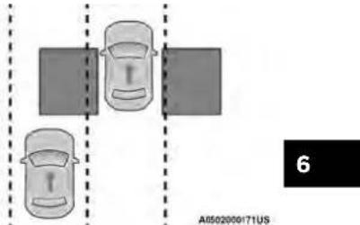
RearDetectionZones
ReadyAlertBraking(RAB)
RAB may reduce the time required to reach fu during emergency braking situations. It anticipates when an emergency braking situation may occur monitoring how fast the throttle is released by driver. The Electronic Brake Control (EBC) system prepare the brake system for a panic stop.
When TSC is functioning, the ESC Activation/ Malfunction Indicator Light will flash, the engine may be reduced and you may feel the brakes applied to individual wheels to attempt to stop the trailer from swaying. TSC is disabled when the well is in the "Partial Off" mode.
power
being When the vehicle is started, the BSM Warning Light v the momentarily illuminate in both outside rearview mirrors to let the driver know that the system is operational. The BSM system sensors operate when the vehicle is any forward gear and enters standby mode when the vehicle is in PARK (P).
RainBrakeSupport(RBS)
RBS may improve braking performance in wet con It will periodically apply a small amount of brake to remove any water buildup on the front brake functions when the windshield wipers are in LO c
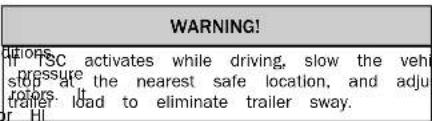
speed. When RBS is active, there is no notification to the driver and no driver interaction is required.
down,
he
The BSM detection zone covers approximately on width on both sides of the vehicle 12 ft (3.7) zone length starts at the outside rearview mirror extends approximately 10 ft (3 m) beyond the fascia/bumper of the vehicle. The BSM system tors the detection zones on both sides of the when the vehicle speed reaches approximately 6 (10 km/h) or higher and will alert the driver in these areas.
NOTE:
- The BSM system DOES NOT alert the driver rapidly approaching vehicles that are outside detection zones.
- The BSM system detection zone DOES NOT if your vehicle is towing a trailer. Therefore, verify the adjacent lane is clear for both y and trailer before making a lane change. If trailer or other object (i.e., bicycle, sports equipment) extends beyond the side of your vehicle may result in false detections. The BSM Wa Light may even remain illuminated the entire vehicle is in a forward page 100.
- The Blind Spot Monitoring (BSM) system may experience dropouts (blinking on and off) of the side or warning indicator lights when a motorcycle or small object remains at the side of the vehicle extended periods of time (more than a couple of seconds).
eThaneBSM system can become blocked if snow, ice, mud, on). other road contaminants accumulate on the rear fassob/bumper where the radar sensors are located. Radar system may also detect blockage if the vehicle is moperated in areas with extremely low radar returns such vehicle desert or parallel to a large elevation drop. If bio-ramh is detected, a "Blind Spot Temporarily Unavailable
of Wipehldear Corners" message will display in the cluster, both mirror lights will illuminate, and BSM and RCP alerts will not occur. This is normal operation. The system will automatically recover and resume function when the condition clears. To minimize system blockage, do not block the area of the rear fascia/bumper where the radar sensors are located with foreign objects (bumper stickers, bicycle racks, etc.) and keep
henglear of road contaminants.
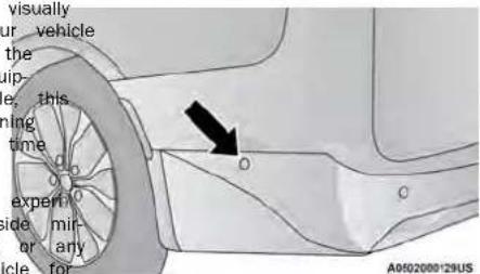
SensorLocation
The BSM system notifies the driver of objects in the detection zones by illuminating the BSM Warning Light located in the outside mirrors in addition to sounding an audible (chime) alert and reducing the radio volume page 124.
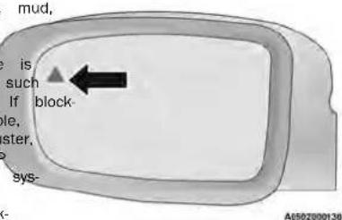
WarningLightLocation
The BSM system monitors the detection zone from three different entry points (side, rear, front) while driving to see if an alert is necessary. The BSM system issue an alert during these types of zone entries.
EnteringFromTheSide
Vehicles that move into your adjacent lanes from either side of the vehicle.
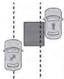
natural_image
Two cars with a central block and a warning sign, separated by dashed lines (no text or symbols)A0502000166US
SideMonitoring
EnteringFromTheRear
Vehicles that come up from behind your vehicle on either side and enter the rear detection zone with a relative speed of less than 30 mph (48 km/h).
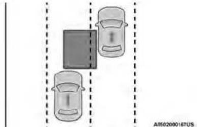
natural_image
Diagram showing two cars positioned at a junction with dashed lines indicating alignment or spacing (no text or symbols)RearMonitoring
OvertakingTraffic
If you pass another vehicle slowly with a relative speed less than 15 mph (24 km/h) and the vehicle remains in the blind spot for approximately 1.5 seconds, the warning light will be illuminated. If the difference in speed between the two vehicles is greater than 15 mph (24 km/h), the warning light will not illuminate.
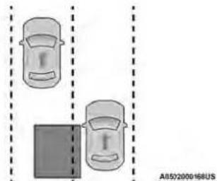
natural_image
Diagram showing two cars parked side by side with a parking lot below (no text or symbols)Overtaking/Approaching
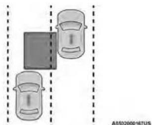
natural_image
Diagram showing two cars with a parking sign and directional arrows, separated by dashed lines (no text or symbols)Overtaking/Passing
The BSM system will not alert you of objects that at traveling in the opposite direction of the vehicle in accent lanes page 231.
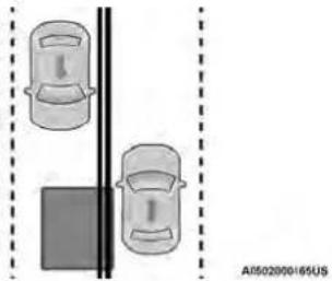
natural_image
Diagram showing two cars positioned vertically against a solid background, with no visible text or symbols.OpposingTraffic
WARNING!
The Blind Spot Monitoring system is only an help detect objects in the blind spot zones. The BSM system is not designed to detect pedestrians, bicyclists, or animals. Even if your vehicle is equipped with the BSM system, always check your vehicle's mirrors, glance over your shoulder, and use your turn signal before changing lanes. Failure to do so can result in serious injury or death.
The BSM system is designed not to issue an alert on stationary objects such as guardrails, posts, walls, foliage, berms, snow banks, car washes, etc. However, occasionally the system may alert on such objects. This is normal operation and your vehicle does not require service.
RearCrossPath(RCP)
RCP is intended to aid the driver when backing parking spaces where their vision of oncoming vehicle may be blocked. Proceed slowly and cautiously of the parking space until the rear end of the vehicle exposed. The RCP system will then have a clear cross traffic and if an oncoming vehicle is alert the driver.
NOTE:
In our parking lot situation, oncoming vehicles closed by vehicles parked on either side. If others are blocked by other structures or vehicle systems will not be able to alert the driver. Your vehicle is obscured by a flat object on system can false alert on vehicles approaching detected opposite direction.
BlindSpotAlertLights/Chime
When operating in Blind Spot Alert Lights/Chime mode, the SASM system will provide a visual alert in the app print the side view mirror based on a detected object. If information signal is then activated, and it corresponds to an said present on that side of the vehicle, an audio frame that will also be sounded. Whenever a turn signal is detected object are present on the same side at the same time, both the visual and audible alerts will be issued. In addition to the audible alert the radio (if I will also be muted.
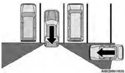
RCPDetectionZones
WARNING! Rear Cross Path Detection (RCP) is not a system. It is intended to be used to help detect an oncoming vehicle in a parking lot. Drivers must be careful when backing up, using RCP. Always check carefully behind your vehicle, look behind you, and be sure to pedestrians, animals, other vehicles, obstructed and blind spots before backing up. Failure can result in serious injury or death.
backup aid a Driver
However an audible alert is requested by the BSM system, the radio is also muted. When the system is in RCP, the system shall respond to check for both visual and audible alerts when a detected status, object is present. Whenever an audible alert is requested, the radio is also muted. Turn/hazard signal status is ignored: the RCP state always requests the chime.
BlindSpotModes
BlindSpotAlertOff
RCP monitors the rear detection zones on both the vehicle, for objects that are moving toward of the vehicle with a minimum speed of approx 3 mph (5 km/h), to objects moving a maximum approximately 20 mph (32 km/h), such as in p situations. When RCP is on and the vehicle is in REVERS driver is alerted using both the visual and audit alarms, including reducing the radio volume.
sides of three selectable modes of operation are aval the side the Uconnect system. imately BlindSpotAlertLightsOnly—DefaultSetting
When the BSM system is turned off there will be no visual or audible alerts from either the BSM or RCP systems.
When operating in Blind Spot Alert mode, the system will provide a visual alert in the appropriate view, mirror based on a detected object. However, the system is operating in Rear Cross Path (the system will respond with both visual and alerts when a detected object is present. When audible alert is requested, the radio is muted.
NOTE:
BSM system will store the current operating mode, when the vehicle is shut off. Each time the vehicle starts the previously stored mode will be recalled and used ever an
FORWARD COLLISION WARNING (FCW) WITH MITIGATION — IF EQUIPPED
FCW with Mitigation provides the driver with audible warnings, visual warnings (within the instrument cluster display), and may apply a brake jerk to warn the driver when it detects a potential frontal collision. The warnings and limited braking are intended to provide the driver with enough time to react, avoid or mitigate the potential collision.
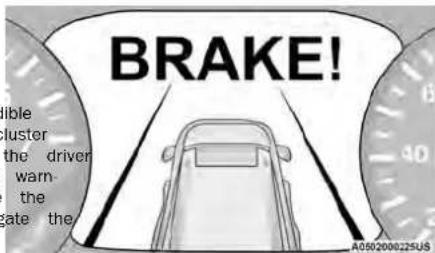
FCWMessage
NOTE:
FCW monitors the information from the forward looking sensors as well as the Electronic Brake Controller. When the system determines a collision with t (EBC), to calculate the probability of a forward vehicle, in front of you is no longer probable. When the system determines that a forward collision is warning message will be deactivated at 231. probable, the driver will be provided with audible and visual warnings and may provide a brake jerk warning.
If the driver does not take action based upon these minimum speed for FCW activation is 1 gressive warnings, then the system will provide a 12 h km/h).
ited level of active braking to help slow the vehicle and mitigate the potential forward collision. If the driver reacts to the warnings by braking and the system mines that the driver intends to avoid the collision by braking but has not applied sufficient brake force, the system will compensate and provide additional brakelt is unsafe to test the FCW system. To prevent force as required. The FCW alerts may be triggered on objects of the vehicle than vehicles such as guardrails or sign post- or the course prediction. This is expected and part of normal FCW activation and functionality.
If an FCW with Mitigation event begins at a special event, we show within a key cycle, the Active Braking Position 37 mph (60 km/h), the system may provide the maxFCW will be deactivated until the next key programable through the Uconnect system mum braking possible to mitigate the potential forward collision. If the Forward Collision Warning with Mitigation event stops the vehicle completely, the system will be deactivated to prevent unnecessary warnings and the system status is "Warning & Braking". This hold the vehicle at standstill for two seconds and then release the brakes. If a pedestrian is encountered in the path at the same speed threshold, the system will also attempt to bring the vehicle to a stop.
WARNING!
Forward Collision Warning (FCW) is not intended to avoid a collision on its own, nor can FCW detect any type of potential collision. The driver has the responsibility to avoid a collision by controlling the vehicle via braking and steering. Failure to follow this warning could lead to serious injury or death.
TurningFCWOnOrOff
The Forward Collision menu setting is located in the Uconnect Settings.
NOTE:
The default status of FCW is "On", this allows the s'tem to warn you of a possible collision with the veh in front of you.
Changing the FCW status to "Off" deactivates teeth so no warning or active braking will be case of a possible collision.
NOTE:
The FCW system state is kept in memory from one cycle to the next. If the system is turned off, it will remain off when the vehicle is restarted.
event such
FCWBrakingStatusAndSensitivity
The FCW Sensitivity and Active Braking status are pro-grammable through the Uconnect system
only page 100.
The default sensitivity of FCW is the "Medium" setting and the system status is "Warning & Braking". This allows the system to warn the driver of a possible c sion with the vehicle in front using audible/visual warn ings and it applies autonomous braking.
Changing the FCW status to the "Far" setting allows the system will retain the last setting selected system to warn the driver of a possible collision while driver after ignition shut down. Pedestrian Emergency Braking (PEB)—If Equipped vehicle in front using audible/visual warning when the FCW may not react to irrelevant objects such as latter is at a farther distance than the "Medium" set overhead objects, ground reflections, objects not in the FDW system that provides the driver with this provides the most reaction time to avoid a path of the vehicle, stationary objects that are possible collision.
NOTE:
The "Far" setting may result in a greater number PCWFCWill be disabled with the unavailable screenstrian/cyclist. possible collision warnings experienced. If a PFB even
Changing the FCW status to the "Near" setting the system to warn the driver of a possible the vehicle in front when the distance between vehicle in the front is much closer. This setting less reaction time than the "Far" and "Medium tings, which allows for a more dynamic driving experience.
NOTE:
The "Near" setting may result in a lesser num FCW possible collision warnings experienced.
FCWLimitedWarning allows
Missione with instrument cluster displays "FCW Limited
thonality" or "FCW Limited Functionality Clean F
“Worried” momentarily, there may be a condi
limits. ECW functionality. Although the vehicle is
drivable under normal conditions, the active bra
unvable under normal conditions, the active plan may not be fully available. Once the condition
may not be fully available. Once the condition ited the system performance is no longer pres
ited the system performance is no longer pres system will return to its full performance state
system will return to its full performance state
problem persists, see an authorized dealer.
If a PEB event begins at a speed below 37 mph (60 km/h), the system may provide braking to mitigate
Furc-potential collision with a pedestrian/cyclist. If the
REB event stops the vehicle completely, the system wil
hold the vehicle at a standstill for two seconds and
release the brakes. When the system determines a col
mission with the pedestrian/cyclist in front of you is no
logerio-probable, the warning message will be
the "Warning" message will be deactivated
The minimum speed for PBP activation is 2 mbh
The minimum speed for PEB activation is 3 mph (5 km/h)
ServiceFCWWarning
If the system turns off, and the instrument clu
NOTE:
- Changing the FCW status to "Only Warning" prevents the system from providing limited active ing, or additional brake support if the driver braking adequately in the event of a potential collision, but maintains the audible and visual warnings.
- Changing the FCW status to "Off" prevents the system from providing autonomous braking, or additional brake support if the driver is not braking adequately in the event of a potential frontal collision.
• Cruise/FCW Unavailable Service Required is not frontal This indicates there is an internal system fault. Although the vehicle is still drivable under norm tions, have the system checked by an authorize
WARNING!
Pedestrian Emergency Braking (PEB) is not intended to avoid a collision on its own, nor can PEB detect every type of potential collision with a pedestrian/cyclist. The driver has the responsibility to avoid a collision by controlling the vehicle via braking and steering. Failure to follow this warning could lead to serious injury or death.
TurningPEBOnOrOff
NOTE:
The default status of PEB is "On." This allows the system to warn you of a possible frontal collision with pedestrian/cyclist.
The PEB button is located in the Uconnect display. The tire pressure will vary with temperature by appraise the tire pressure to approximately 24 psi. Controls settings page 100. To turn the PEB system off, push the Pedestrian Emergency Braking OFF button. To turn the PEB system back on, push the Warning Active Braking button. Changing the PEB status to "Off" deactivates the wire (1.6 km) after a three hour period. The needed tire cold placard pressure value page 231. No. of a possible frontal collision with the pedestrian/cyclist. The tire pressure must not exceed the maximum inflation pressure molded into the tire sidewall. The tire pressure will also increase as the vehicle is driven when Thilling warm tires, the tire pressure may need to
NOTE:
The PEB system will NOT retain the last setting selected pressure. See page 207 for information on how to properly reset to the default setting when the vehicle is inflate the vehicle's tires. The TPMS will warn the driver of a low tire pressure if CAUTION!
TIRE PRESSURE MONITORING SYSTEM (TPMS)
The Tire Pressure Monitoring System (TPMS) will rupture as long as the condition exists, and will not be stopped on your vehicle. The pressure is the driver of a low tire pressure based on the vehicle turn-off until the tire pressure is at or above the operation or sensor damage may result when recommended cold placard pressure. Once the low tire being replacement equipment that is not of the same size type and/or style. The TPMS sensor is
NOTE:
The TPMS Warning Light will illuminate in the instrument cluster and a chime will sound when tire pressure is low in one or more of the four active road. The system will automatically update and the TPMS addition, the instrument cluster will display a gravening Light will turn off once the system receives the showing the pressure values of each tire with updated tire pressures. The vehicle may need to be tire pressure values in a different color, or the drone mount up to 20 minutes above 15 mph (24 psi) using aftermarket tire sealants may cause the radio will display a TPMS message. When this order for the TPMS to receive this information, you must increase the tire pressure to the record for example, your vehicle may have a recommended cold placard pressure in order for the TPMS (parked for more than three hours) placard pressure of 33 psi (227 kPa). If the ambient temperature is 68°F (20°C) and the measured tire pressure is 28 psi (193 kPa), a temperature drop to 20°F (-7°C) will (Continued)
| pressure ifCAUTION! |
| rects the TPMS has been optimized for the on equipment tires and wheels. TPMS pressure waring have been established for the tire all uppelled on your vehicle. Undesirable syste operation or sensor damage may result w using replacement equipment that is not o same size, type, and/or style. The TPMS not designed for use on aftermarket whee may contribute to a poor overall system mance or sensor damage. Customers are aged to use Original Equipment Manufacture OEMI wheels to ensure proper TPMS feat operation. |
| rning |
| MSives the be working aftermarket tire sealants may cause Pressure Monitoring System (TPMS) sensor b becoming inoperable. After using an aftermar sealant it is recommended that you take vehicle to an authorized dealer to have y operation checked. |
(Continued)
CAUTION!
- After inspecting or adjusting the tire press always reinstall the valve stem cap. This vent moisture and dirt from entering the stem, which could damage the TPMS sens
NOTE:
- The TPMS is not intended to replace normal care and maintenance, or to provide warning tire failure or condition.
- The TPMS should not be used as a tire p gauge while adjusting your tire pressure.
- Driving on a significantly underinflated tire can the tire to overheat and can lead to tire underinflation also reduces fuel efficiency and tread life, and may affect the vehicle's hand stopping ability.
- The TPMS is not a substitute for proper tire nance, and it is the driver's responsibility to lain correct tire pressure using an accurate pressure gauge, even if underinflation has not reached the level to trigger illumination of the Warning Light.
- Seasonal temperature changes will affect tire sure, and the TPMS will monitor the actual sure in the tire.
PremiumSystem
The Tire Pressure Monitoring System (TPMS) uses less technology with wheel rim mounted electronic sors to monitor tire pressure levels. Sensors, mo to each wheel as part of the valve stem, trans pressure readings to the receiver module.
NOTE:
It is particularly important for you to check the sure in all of the tires on your vehicle month! I may contain the proper pressure.
The TPMS consists of the following components:
- Receiver module
• Four Tire Pressure Monitoring System sensors
- Various Tire Pressure Monitoring System message which display in the instrument cluster
tire Tire Pressure Monitoring System Warning Light
SERVICETPMSWARNING
When a system fault is detected, the Tire Pressure Monitoring System (TPMS) Warning Light will flash off and off for 75 seconds and then remain on solid systems. The system fault will also sound a chime. In addition, the instrument cluster will display a "SERVICE TPM SYSTEM" message for a minimum of five seconds and
display dashes (-) in place of the pressure value cate which sensor is not being received. 4.
If mainte-ignition is cycled, this sequence will repeat.
main the system fault still exists. If the system
Viding the system fluid still exists. If the system
flash, and the "SERVICE TPM SYSTEM" message wi
TPMS longer display, and a pressure value will display in
of the dashes. A system fault can occur due to
the following:
res- following.
fire Jamming due to electronic devices or driving ne
facilities emitting the same radio frequencies as
facilities – affecting the same radio frequencies as TPMS cancers
TPMS sensors
• Installing some form of aftermarket window tinting
...that affects radio wave signals
- Installing some form of aftermarket window tinting that affects radio wave signals
wire- a little radio have signals
wire- a little radio have signals
● lots of show or ice around the wheels or wh
unten housings
smitUsing tire chains on the vehicle
• Using wheels/tires, net equipped with TPMS sensor
VehiclesWithCompactSpare—IfEquipped
The compact spare tire does not have a Tire Pressu and to Monitoring System sensor. Therefore, the TPMS will not monitor the pressure in the compact spare tire.
- If you install the compact spare tire in place of a tire that has a pressure below the low-pressure
warning limit, the "Inflate to XX" message will con-
Stinue to be displayed. Upon the next ignition cycle, 1 TPMS Warning Light will remain on and a chime will sound. In addition, the graphic in the instrument cluster will still display a different color pressure value.
- After driving the vehicle for up to 20 minutes above 15 mph (24 km/h), the TPMS Warning Light will
9ash on and off for 75 seconds and then remain
d Solid The In addition the instrument cluster will display
a the SERVICE TPM SYSTEM" message for five seconds
a "SERVICE" TPM SYSTEM message for five seconds
and then display dashes (--) in place of the press, d., then
value: to indi
For each subsequent ignition cycle a chime will
For such subsequent ignition cycle, a phone will sound the TRMO. Warning light will flash on and
sound, the TPMS Warning Light will flash on and (
f_g _ult 75 seconds and then remain on solid, and the
Instrument cluster will display a "SERVICE TPM SYS-
ger "TEM" message for five seconds and then display
in Evi no message for five seconds and then display
dashes (- -) in place of the pressure value.
One of you repair an replace the original reel tire
once o/you repair or replace the original road tire a
reinstall it on the vehicle in place of the compact
esbate, the TPMS will undate automatically. In addi-
tike the TRMS Warning Light will turn off and the
table, the TPMS Warning Light will turn on and the
graphic in the instrument cluster will display a new
pressure value instead of dashes (--), as long as r
tire pressure is below the low-pressure warning limit
are pressure is below the low pressure warning limit in any of the four active road tires. The vehicle
feel any of the four active road tires. The vehicle
need to be driven for up to 20 minutes above 1
mph (24 km/h) in order for the TPMS to receive
information
information. ors
315
TIREPRESSUREMONITORINGSYSTEMLOW PRESSUREWARNINGS

The TPMS Warning Light will illuminate instrument cluster and a chime will so when tire pressure is low in one or the four active road tires. In addition,
instrument cluster will display an "Inflate to XX sage and a graphic showing the pressure value each tire with the low tire pressure values in color.
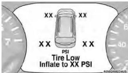
TirePressureMonitoringSystem
Should this occur, you should stop as soon as and inflate the tires with low pressure (those) ent color in the instrument cluster graphic) to cle's recommended cold placard pressure value shown in the "Inflate to XX" message. Once t receives the updated tire pressures, the system automatically update, the pressure values in the graphic display in the instrument cluster will re their original color, and the TPMS Warning Light turn off. The vehicle may need to be driven 20 minutes above 15 mph (24 km/h) in ord TPMS to receive this information.
TPMSDEACTIVATION—IFEQUIPPED
The Tire Pressure Monitoring System (TPMS) can be deactivated if replacing all four wheel and tire as one of the most important safety features in your biles (road tires) with wheel and tire assemblies vehicle gear the restraint systems:
not have TPMS sensors, such as when installing more or wheel and tire assemblies on your vehicle.
Times deactivate the TPMS, first, replace all four which has still of assemblies (road tires) with tires not equipped with Seat Belt Systems
the vehicle for 20 minutes above 15 mph (24 km/h) Supplemental Restraint Systems (SRS) Air Bags The TPMS will chime, the TPMS Warning Light will Chinch Restraints
on and off for 75 seconds and then remain on. The of the safety features described in this section instrument cluster will display the "SERVICE TPM" may be standard equipment on some models, or may TEM" message and then display dashes (-) in place of the optional equipment on others. If you are not sure, the pressure values. ask an authorized dealer.
Beginning with the next ignition cycle, the TPMS will no longer chime or display the "SERVICE TPM SYSTEM IMPORTANT SAFETY PRECAUTIONS
message in the instrument cluster but dashes (-) will remain in place of the pressure values. Please pay close attention to the information section. It tells you how to use your restraint to reactivate the TPMS, replace all four wheel assemblies (road tires) with tires equipped with TPMS possible.
sensors. Then, drive the vehicle for up to 20 minutes above 15 mph (24 km/h). The TPMS will chime the risk of harm from a deploying air bag: TPMS Warning Light will flash on and off for 75 seconds
a position turn off. The instrument cluster will display children 12 years old and under should always rid in SERVOfferTPM SYSTEM" message and then display buckled up in the rear seat of a vehicle with a pressure values in place of the dashes. On the next.
ignition cycle the "SERVICE TPM SYSTEM" message, will not be displayed as long as no system fault. A child who is not big enough to wear the vehicle is a seat belt properly must be secured in the appropriate child restraint or belt-positioning booster seat in a rear seating position page 147.
-
If a child from 2 to 12 years old (not in a re child restraint) must ride in the front passenger seat, move the seat as far back as possible and the proper child restraint page 147.
-
Never allow children to slide the shoulder behind them or under their arm.
- You should read the instructions provided child restraint to make sure that you are properly.
- All occupants should always wear their lap shoulder belts properly.
- The driver and front passenger seats should moved back as far as practical to allow the bags room to inflate.
- Do not lean against the door or window, vehicle has side air bags, and deployment the side air bags will inflate forcefully into between occupants and the door and occup could be injured.
- If the air bag system in this vehicle needs modified to accommodate a disabled person, page 228 for customer service contact information.
WARNING!
- Never place a rear-facing child restraint in an air bag. A deploying passenger front cause death or serious injury to a child younger, including a child in a rear-facing restraint.
- Never install a rear-facing child restraint in front seat of a vehicle. Only use a rear restraint in the rear seat. If the vehicle have a rear seat, do not transport a re child restraint in that vehicle.
beET SEAT BELT SYSTEMS
Buckle up even though you are an excellent
on your short trips. Someone on the road may be
ing it and could cause a collision that includes
This can happen far away from home or on
street.
Research has shown that seat belts save lives
Research has shown that seat belts save lives can reduce the consequences of injuries in a car
can reduce the seriousness of injuries in a co
Some of the worst injuries happen when people front air
thrown from the vehicle. Seat belts reduce the
ity of ejection and the risk of injury caused
theurinside of the vehicle. Everyone in a motor
csould be belted at all times.
he space
tEnhancedSeatBeltUseReminder
System(BeltAlert)
DriverAndPassengerBeltAlert—IfEquipped

BeltAlert feature is active whenever the
is in the START or ON/RUN position.
dattialadication
years of driver is unbuckled when the
If the driver is unbackled when the if d ret in the START or ON/RUN position
first in the START of ON/RUN position,
nal for a few seconds. If the driver
Seat passenger (if equipped with outboa
ng child (enger seat BeltAlert) is unbuckled whe
s switch is first in the START or ON/RL
Cirglt Reminder Light will turn on and
both outboard front seat belts are but
both outboard front seat belts are buckled. The board front passenger seat BeltAlert is not active ^1
board front passenger seat BellAlert is not active when
an outboard front passenger seat is unoccupied.
BeltAlertWarningSequence
The BeltAlert warning sequence is activated when the
river, even vehicle is moving above a specified vehicle speed range
a poor and the driver or outboard front seat passenger is
and the driver of outboard front seat passenger is you. Unbuckled (if equipped with outboard front passenger
unbuckled (in equipped with outboard front passenger your own) (the outboard front passenger cost
seat BeltAlert) (the outboard front passenger seat
BeltAlert is not active when the outboard front passen-
ger and seat they is unoccupied). The BeltAlert warning
sequence starts by blinking the Seat Belt Reminder
eLight and sounding an intermittent chime. Once the
possible warning sequence has completed, the Seat
Bel striking Reminder Light will remain on until the seat belt
vehicle. The BeltAlert warning sequence may
are - baclical. The Bois short Warning Sequence may repeat based on vehicle speed until the driver
repeat based on vehicle speed under the driver and occupied, outboard front seat passenger seat belts are
occupied outboard front seat passenger seat belts are buckled. The driver should instruct all occupants to
buckled. The driver should instruct all occupants to
buckle tr
ChangeOfStatus
nd the driver or outboard front seat passenger
if equipped with outboard front passenger seat
(BeltAlert) unbuckles their seat belt while the vehicle is
traveling, the BeltAlert warning sequence will begin
which the seat belts are buckled again.
The outboard front passenger seat BeltAlert is not
active when the outboard front passenger seat is unoc
cupied. BeltAlert may be triggered when an animal or
other is items are placed on the outboard front passenger
e will or sig when the seat is folded flat (if equipped). It
ard frontended that, pets, be restrained in the rear seat.
Recommended that pets be restrained in the real seat
(Hasequipped) in pet harnesses or pet carriers that are
"secured by seat belts, and cargo is properly stowed.
n the Seat BelfAlert can be activated or deactivated by an autho-
n. until rized dealer ECA US LLC does not recommend deacti-
nized dealer. For US EES does not recommend debetiv- out- voting . BeltAlert
vating BellAlert.ve when
2017.2.1
NOTE:
If BeltAlert has been deactivated and the driver board front seat passenger (if equipped with out front passenger seat BeltAlert) is unbuckled the Belt Reminder Light will turn on and remain on driver and outboard front seat passenger seat buckled.
Lap/ShoulderBelts
All seating positions in your vehicle are equipped lap/shoulder belts.
The seat belt webbing retractor will lock only due very sudden stops or collisions. This feature allows shoulder part of the seat belt to move freely under normal conditions. However, in a collision seat belt will lock and reduce your risk of strike inside of the vehicle or being thrown out of the
WARNING!
- Relying on the air bags alone could lead to severe injuries in a collision. The air bags w your seat belt to restrain you properly. In so lisions, the air bags won't deploy at all. Alw wear your seat belt even though you have a
- In a collision, you and your passengers can much greater injuries if you are not properly led up. You can strike the interior of your other passengers, or you can be thrown out vehicle. Always be sure you and others in y vehicle are buckled up properly.
- It is dangerous to ride in a cargo area, ins outside of a vehicle. In a collision, people r these areas are more likely to be seriously or killed.
to more
work with
some col-
WARNING!
or out-
soa do not allow people to ride in any area of y Seal that is not equipped with seats and seat belts.
- until the everyone in your vehicle is in a seat using a seat belt properly. Occupants, including driver, should always wear their seat belts who or not an air bag is also provided at their position to minimize the risk of severe injury death in the event of a crash.
- Wearing your seat belt incorrectly could make your injuries in a collision much worse. You might view internal injuries, or you could even slide out with seabu belt. Follow these instructions to wear your the belt safely and to keep your passengers safe, giving the people should never be belted into a single vehicle. People belted together can crash into one another in a collision, hurting one another bad! Never use a lap/shoulder belt or a lap belt than one person, no matter what their size.
WARNING!
Aparap belt worn too high can increase the surinjury in a collision. The seat belt forces with the strong hip and pelvic bones, but across vehicle abdomen. Always wear the lap part of your of bottle as low as possible and keep it snug.
A twisted seat belt may not protect you a collision, it could even cut into you. Bideseat belt is flat against your body, without dingouin can't straighten a seat belt in your injutade it to an authorized dealer immediately have it fixed.
WARNING!
our A vehicle belt that is buckled into the wrong buckle will not protect you properly. The lap portion could at ride too high on your body, possibly causing inter- the injuries. Always buckle your seat belt into the buckle nearest you.
seAtingeat belt that is too loose will not protect you or properly. In a sudden stop, you could move too far forward, increasing the possibility of injury. Wear your seat belt snugly.
suffer seat belt that is worn under your arm is dang if thus. Your body could strike the inside surfaces of r seat vehicle in a collision, increasing head and neck to injury. A seat belt worn under the arm can cause gle internal injuries. Ribs aren't as strong as shoulder bones. Wear the seat belt over your shoulder so y. that your strongest bones will take the force in a collision.
- A shoulder belt placed behind you will not you from injury during a collision. You are more likely to hit your head in a collision if you do n wear your shoulder belt. The lap and shoulder belt are meant to be used together.
A offrayed or torn seat belt could rip apart in a don't shen and leave you with no protection. Inspect the you'seat belt system periodically, checking for cuts, seatrays, or loose parts. Damaged parts must be replaced immediately. Do not disassemble or perlymodify the seat belt system. If your vehicle is sure involved in a collision, or if you have questions vists regarding seat belt or retractor conditions, take place, your vehicle to an authorized FCA dealer or authorized FCA Certified Collision Care Program facility for inspection.
Lap/ShoulderBeltOperating Instructions
- Enter the vehicle and close the door. Sit back and adjust the seat.
- The seat belt latch plate is above the back of the front seat, and next to your arm in the rear seat (for vehicles equipped with a rear seat). Grab the latch plate and pull out the seat belt. Slide the latch plate up the webbing as far as necessary to allow the seat belt to go around your lap.
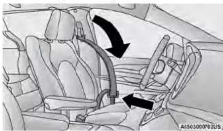
natural_image
Interior view of a car showing seat, dashboard, and steering wheel (no text or symbols)PullingOutTheLatchPlate
- When the seat belt is long enough to fit, 5asePosition the shoulder belt across the shoulder and latch plate into the buckle until you hear a "obest with minimal, if any slack so that it is com
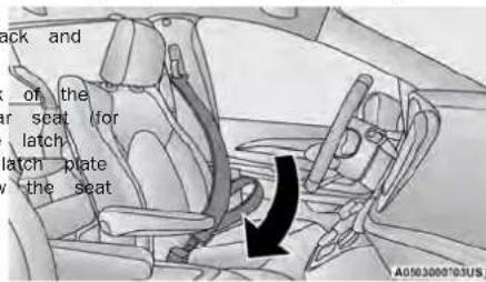
InsertingLatchPlateIntoBuckle
- Position the lap belt so that it is snug and lies above about 6 to 12 inches (15 to 30 cm) above across your hips, below your abdomen. To remove latch plate, grab and twist the seat belt webbing slack in the lap belt portion, pull up on the shoulder degrees to create a fold that begins immediately. To loosen the lap belt if it is too tight, till the latch above the latch plate. Plate and pull on the lap belt. A snug seat belt reduces the risk of sliding under the seat belt in a collision.
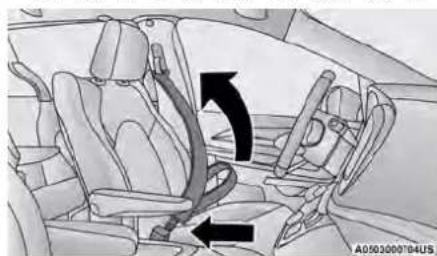
natural_image
Interior view of a car showing seatbelt and dashboard with directional arrows indicating movement (no text or symbols)PositioningTheLapBelt
- To release the seat belt, push the red button on buckle. The seat belt will automatically retract to its stowed position. If necessary, slide the latch plate down the webbing to allow the seat belt to retract fully.
Lap/ShoulderBeltUntwistingProcedure
Use the following procedure to untwist a twisted lap/shoulder belt.
- Position the latch plate as close as possible to anchor point.
- A low about 6 to 12 inches (15 to 30 cm) above
above latch plate, grab and twist the seat belt webbing
shoulder degrees to create a fold that begins immedi-
tily above the latch plate.
belt reduces - Slide the latch plate upward over the folded web- collision. The folded webbing must enter the slot at the top of the latch plate.
- Continue to slide the latch plate up until it clears folded webbing and the seat belt is no longer twisted.
AdjustableUpperShoulderBelt Anchorage
In the front and second row outboard seats the der belt can be adjusted upward or downward tion the seat belt away from your neck. Push the anchorage button to release the anchorage, move it up or down to the position that serve
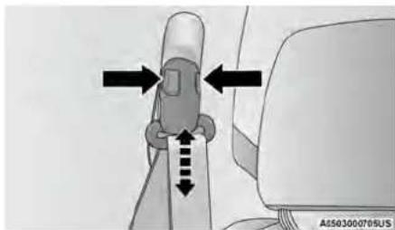
AdjustableAnchorage
As a guide, if you are shorter than average, for the shoulder belt anchorage in a lower point if you are taller than average, you will prefer der belt anchorage in a higher position. After release the anchorage button, try to move it to make sure that it is locked in position.
NOTE:
The adjustable upper shoulder belt anchorage is seats w equipped with an Easy Up feature. This feature allows the shoulder belt anchorage to be adjusted in the upward position without pushing or squeezing the release button. To verify the shoulder belt anchorage is latched, pull downward on the shoulder belt anchorage until it is locked into position.
WARNING!
- Wearing your seat belt incorrectly could make snour. Injuries in a collision much worse. You might or internal injuries, or you could even slide out or squeeze. Seat belt. Follow these instructions to wear y and seat belt safely and to keep your passengers you best.
- Position the shoulder belt across the shoulder chest with minimal, if any slack so that it fortable and not resting on your neck. The will withdraw any slack in the shoulder belt.
- Misadjustment of the seat belt could reduce effectiveness of the safety belt in a crash.
- Always make all seat belt height adjustments the vehicle is stationary.
SecondRowCenter(IfEquipped)And ThirdRowCenterSeatBeltOperating Instructions
you will pre- tion, second row center (if equipped) and third row cen- ter seat belts feature a seat belt with a mini-latch plate and buckle, which allows the seat belt to detach from the lower anchor when the seat is folded. The mini-latch plate and regular latch plate can then be stored out of the way in the headliner for added convenience to open up utilization of the storage areas behind the front seats when the seat is not occupied.
- Remove the mini-latch plate and regular latch plate from its stowed position in the headliner slightly behind the second or third row seat.
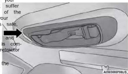
Mini-LatchStowage
- Grab the mini-latch plate and pull the seat belt of the seat.
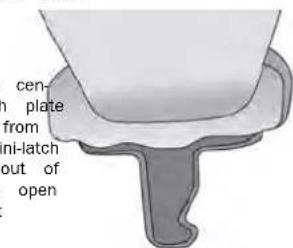
Mini-LatchPlate
- Route the shoulder belt to the inside of restraint.
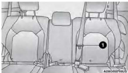
natural_image
Interior view of a car showing rear seats and seatbelt (no text or symbols visible)RoutingTheRearSeatBeltLatchPlate
1 - Seat Belt Latch Plate
- When the seat belt is long enough to fit, mini-latch plate into the mini-buckle until you "click."
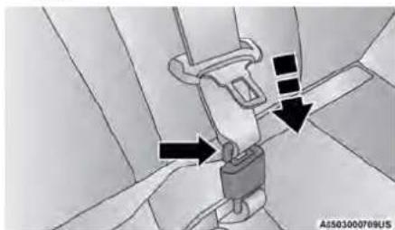
natural_image
Illustration of a car seatbelt buckle being adjusted, showing rope routing and adjustment arrows (no text or symbols)ConnectMini-LatchPlateToMini-Buckle
the5.le\$it headk in seat. Slide the regular latch webbing as far as necessary to allow the go around your lap.
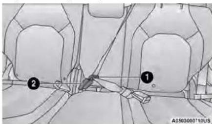
natural_image
Technical diagram of a vehicle interior showing two labeled parts (① and ②) with no readable text or symbols.RearCenterSeatBeltBuckled
1 - Seat Belt Latch Plate insert seat Belt Buckle
hear a 6. When the seat belt is long enough to fit, latch plate into the buckle until you hear a
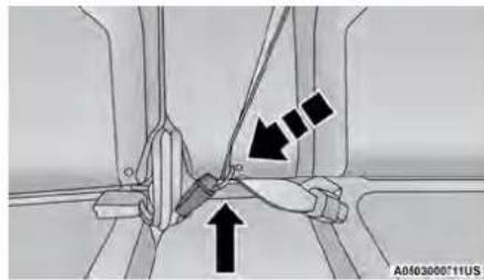
natural_image
Mechanical assembly diagram showing a clamp and lever mechanism (no text or symbols)LatchPlateAndBuckleConnected
plate Position the lap belt so that it is snug and lies seat above to your hips, below your abdomen. To remove slack in the lap belt portion, pull up on the shou belt. To loosen the lap belt if it is too tight, pull the lap belt. A snug seat belt reduces the risk of sliding under the seat belt in a collision.
- Position the shoulder belt on your chest so that i comfortable and not resting on your neck. The retractor will withdraw any slack in the seat belt.
- To release the seat belt, push the red button on buckle.
- To disengage the mini-latch plate from the mini-buckle for storage, insert the regular latch plate into the center red slot on the mini-buckle. The seat belt will automatically retract to its stowed position. If necessary, slide the latch plate down the webbing to allow the seat belt to retract fully Insert the mini-latch plate and regular latch plate into its stowed position.
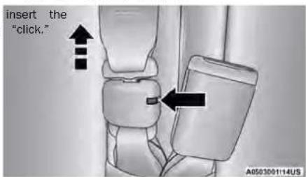
InsertRegularLatchPlateIntoMini-BuckleSlotTo Detach
WARNING!
- If the mini-latch plate and mini-buckle are properly connected when the seat belt is an occupant, the seat belt will not be provide proper restraint and will increase the injury in a collision.
- When reattaching the mini-latch plate and buckle, ensure the seat belt webbing is twisted. If the webbing is twisted, follow ceding procedure to detach the mini-latch and mini-buckle, untwist the webbing, and tach the mini-latch plate and mini-buckle.
WARNING!
not using a Seat Belt Extender when not needed to increase the risk of serious injury or death collision. Only use the Seat Belt Extender lap belt is not long enough and only use 10000000000000000000000000000000000000000000000000000000000000
the pre plate SeatBeltsAndPregnantWomen
plate reat-
SeatBeltExtender
If a seat belt is not long enough to fit properly, even when the webbing is fully extended and the adjustable upper shoulder belt anchorage (if equipped) is in its lowest position, an authorized dealer can provide you with a Seat Belt Extender. The Seat Belt Extender should be used only if the existing seat belt is not for enough. When the Seat Belt Extender is not required for a different occupant, it must be removed.
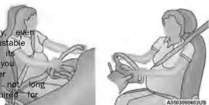
SeatBeltsAndPregnantWomen
WARNING!
- ONLY use a Seat Belt Extender if it is required in order to properly fit the original belt system. DO NOT USE the Seat Belt when worn, the distance between the front of the Seat Belt Extender buckle and the other occupant's body is LESS than 6 inch
Seat belts must be worn by all occupants in pregnant women: the risk of injury in the evening accident is reduced for the mother and the upper safety if they are wearing a seat belt.
nt ePgeitionf the lap belt snug and low below the enterandf across the strong bones of the hips. Pla
es. shoulder belt across the chest and away from Never place the shoulder belt behind the back the arm.
SeatBeltPretensioner
The front outboard seat belt system is equipped with pretensioning devices that are designed to remove slack from the seat belt in the event of a collision. These devices may improve the performance of the seat belt by removing slack from the seat belt early collision. Pretensioners work for all size occupants, including those in child restraints.
NOTE:
These devices are not a substitute for proper seat be placement by the occupant. The seat belt still must be worn snugly and positioned properly.
The pretensioners are triggered by the Occupant Restraint Controller (ORC). Like the air bags, the preterm sioners are single use items. A deployed pretensioner or a deployed air bag must be replaced immediately.
EnergyManagementFeature
The front outboard seat belt system is equipped. Energy Management feature that may help further reduce the risk of injury in the event of a collision, seat belt system has a retractor assembly that is designed to release webbing in a controlled manner.
SwitchableAutomaticLocking
Retractors(ALR)
the seat belts in the passenger seating positions are equipped with a Switchable Automatic Locking Retractor (ALR) which is used to secure a child restraint system page 155.
The figure below illustrates the locking feature for each seating deposition.
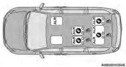
SevenPassengerBenchSeatAutomaticLocking Retractor(ALR)Locations
ALR — Switchable Automatic Locking Retractor
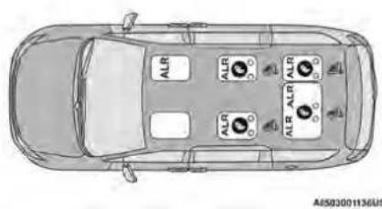
SevenPassengerStow'nGoSeatingAutomaticLocking Retractor(ALR)Locations
ALR — Switchable Automatic Locking Retractor
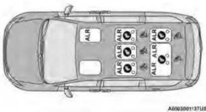
EightPassengerAutomaticLockingRetractor(ALR) Locations
ALR — Switchable Automatic Locking Retractor
If the passenger seating position is equipped with ALR and is being used for normal usage, only seat belt webbing out far enough to comfortably around the occupant's mid-section so as to not the ALR. If the ALR is activated, you will hear
sound as the seat belt retracts. Allow the web retract completely in this case and then carefully out only the amount of webbing necessary to comply wrap around the occupant's mid-section. Slide latch plate into the buckle until you hear a "c
In Automatic Locking Mode, the shoulder belt is matically pre-locked. The seat belt will still retrae remove any slack in the shoulder belt. Use the matic Locking Mode anytime a child restraint is installed in a seating position that has a seat this feature. Children 12 years old and under s always be properly restrained in the rear seat vehicle with a rear seat.
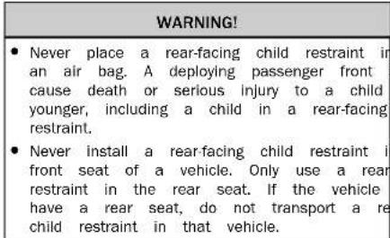
HowToEngageTheAutomaticLockingMode
- Buckle the combination lap and shoulder belt.
- Grab the shoulder portion and pull downward until th the entire seat belt is extracted.
3pullAllolve the seat belt to retract. As the seat belt wrepacts, you will hear a clicking sound. This indi-actuate the seat belt is now in the Automatic Lockir aModlaking
HowToDisengageTheAutomaticLockingMode
Unpull Unpuckle the combination lap/shoulder belt and allow comfort to retract completely to disengage the Automatic Locking Mode and activate the vehicle sensitive (emergency) locking mode.
| t to Auto- | WARNING! |
| ●The seat belt assembly must be replaced belt with switchable Automatic Locking Retractor (ALR) should use or any other seat belt function is of a properly when checked according to the p dures in the Service Manual. | |
(Continued)
WARNING!
- Failure to replace the seat belt assembly increase the risk of injury in collisions.
- Do not use the Automatic Locking Mode occupants who are wearing the seat belt dren who are using booster seats. The I mode is only used to install rear-facing facing child restraints that have a harness restraining the child.
SeatBeltParkStitch—IfEquipped
The rear outboard seat belts may be equipped park stitch to raise the latch plate for easier occupants. If the park stitch interferes with the installation of a child restraint, slide the latch the stitching to shorten the lap portion of the install the car seat normally. When the car seat removed from the vehicle, slide the latch plate the park stitch to enable occupants to latch the belt securely.
ThirdRowStowClip—IfEquipped
Your vehicle may be equipped with a stow could lower trim behind the third row. This clip is the seat belt out of the path of the power to restrate. Only place the seat belt webbing or while folding and opening the seat. Do not locked webbing behind the clip when using the belt or forward occupant.
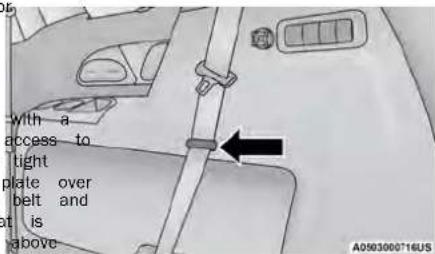
ThirdRowStowClip
SUPPLEMENTAL RESTRAINT SYSTEMS (SRS)
Some third the safety features described in this section they do standard equipment on some models, or may be optional equipment on others. If you are not sure, ask an authorized dealer.
The air bag system must be ready to protect you in collision. The Occupant Restraint Controller (ORC) monitors the internal circuits and interconnecting wiring associated with the electrical Air Bag System Components. Your vehicle may be equipped with the following Air Bag System Components:
AirBagSystemComponents
- Occupant Restraint Controller (ORC)
• Air Bag Warning Light
• Steering Wheel and Column - Instrument Panel
- Knee Impact Bolsters
• Driver and Front Passenger Air Bags - Seat Belt Buckle Switch
• Supplemental Side Air Bags
the • third Supplemental Knee Air Bags
restrain an Front and Side Impact Sensors
d prop- re Seat Belt Pretensioners
- Seat Track Position Sensors
• Occupant Classification System
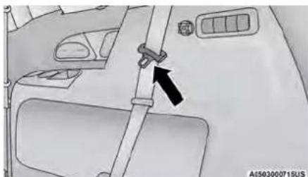
SeatBeltParkStitchLocation
WARNING!
Do not place the seat belt webbing behind the row stow clip when using the seat belt to re occupant. The seat belt will not be positioned early on the occupant and they could be moreously injured in an accident as a result.
AirBagWarningLight

The Occupant Restraint Controller (ORC) monitors the readiness of the electronic parts of the air bag system whenever ignition switch is in the START or ON position. If the ignition switch is in the OFF po the ACC position, the air bag system is not on air bags will not inflate.
The ORC contains a backup power supply system may deploy the air bag system even if the bat power or it becomes disconnected prior to deploy. The ORC turns on the Air Bag Warning Light in instrument panel for approximately four to eight onds for a self-check when the ignition switch is the ON/RUN position. After the self-check, the Air Warning Light will turn off. If the ORC detects function in any part of the system, it turns on Bag Warning Light, either momentarily or continuous
A single chime will sound to alert you if the on again after initial startup.
The ORC also includes diagnostics that will illuminate the instrument panel Air Bag Warning Light if a function is detected that could affect the air bag term. The diagnostics also record the nature of the function. While the air bag system is designed to maintenance free, if any of the following occurs, an authorized dealer service the air bag system immediately.
- The Air Bag Warning Light does not come the four to eight seconds when the ignition first in the ON/RUN position.
• The Air Bag Warning Light remains on after to eight-second interval.
- The Air Bag Warning Light comes on intermittently or remains on while driving.
NOTE:
If the speedometer, tachometer, or any engine gauges are not working, the Occupant Restraiser (ORC) may also be disabled. In this conc bags may not be ready to inflate for your CUN have an authorized dealer service the air bay
immediately. and the
that WARNING!
very loses ignoring the Air Bag Warning Light in your mention panel could mean you won't have the air to the protect you in a collision. If the light on as a bulb check when the ignition is on first stays on after you start the vehicle, c on as you drive, have an authorized dealer and make air bag system immediately. the Air
RedundentAirBagWarningLight

If a fault with the Air Bag Warning Light is detected, which could affect the Supplemental Restraint System (SRS), the Redundant Air Bag Warning Light will illuminate on the
the mal- Instrument panel. The Redundant Air Bag Warning Light
Will be stay on until the fault is cleared. In addition,—a Driver And Passenger Front Air Bags single chime will sound to alert you that the Redundant River Knee Impact Bolster/Supplemental Driver Air Bag Warning Light has come on and a fault,has Air Bag been detected. If the Redundant Air Bag Warning Light Passenger Knee Impact Bolster/Supplemental Pass- controlling intermittently or remains on while driverer Knee Air Bag
Switveh is authorized dealer service the vehicle immediately page 65.
FrontAirBags
related This vehicle has front air bags and lap/shoulder belts on both the driver and front passenger. The front air bag are a supplement to the seat belt restraint sys- tions. The driver front air bag is mounted in the cer of the steering wheel. The passenger front air bag is mounted in the instrument panel, above the glove com partment. The words "SRS AIRBAG" or "AIRBAG" are embossed on the air bag covers.
instrument
ag system does not co first turned.
if it con service
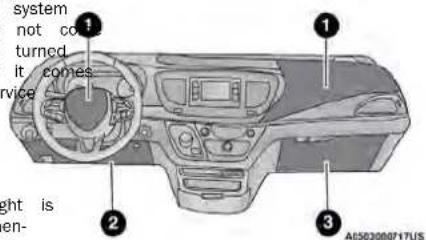
FrontAirBag/KneeBolsterLocations
river And Passenger Front Air Bags silver Knee Impact Bolster/Supplemental Driver
r Bag
passenger Knee Impact Bolster/Supplemental Pas-
Knee Air Bag
(1) AD = BD = 1
The Ground Truth image displays a single, solid horizontal line. According to Rule 2 (UNDERSCORE & LINE RULES), this is a stylistic or background line, not a placeholder underscore. Therefore, the OCR result must ignore it and output nothing or only meaningful text. The provided OCR content is "____", which consists of four underscores. This is an incorrect interpretation of the line as a placeholder, violating the rule that stylistic lines must be ignored. The OCR has hallucinated placeholder underscores where none exist in the GT. Hence, the result is inconsistent with the Ground Truth.
[Non-Text]
[Non-Text]
[Non-Text]
[Non-Text]
[Non-Text]
[Non-Text]
[Non-Text]
[Non-Text]
[Non-Text]
[Non-Text]
[Non-Text]
[Non-Text]
[Non-Text]
[Non-Text]
[Non-Text]
[Non-Text]
[Non-Text]
[Non-Text]
[Non-Text]
[Non-Text]
[Non-Text]
[Non-Text]
[Non-Text]
[Non-Text]
[Non-Text]
[Non-Text]
[Non-Text]
[Non-Text]
[Non-Text]
[Non-Text]
[Non-Text]
[Non-Text]
[Non-Text]
[Non-Text]
[Non-Text]
[Non-Text]
[Non-Text]
[Non-Text]
[Non-Text]
[Non-Text]
[Non-Text]
[Non-Text]
[Non-Text]
[Non-Text]
[Non-Text]
[Non-Text]
[Non-Text]
[Non-Text]
[Non-Text]
[Non-Text]
[Non-Text]
[Non-Text]
[Non-Text]
[Non-Text]
[Non-Text]
[Non-Text]
[Non-Text]
[Non-Text]
[Non-Text]
[Non-Text]
[Non-Text]
[Non-Text]
[Non-Text]
[Non-Text]
[Non-Text]
[Non-Text]
[Non-Text]
[Non-Text]
[Non-Text]
[Non-Text]
[Non-Text]
[Non-Text]
[Non-Text]
[Non-Text]
[Non-Text]
[Non-Text]
[Non-Text]
[Non-Text]
[Non-Text]
[Non-Text]
[Non-Text]
[Non-Text]
[Non-Text]
[Non-Text]
[Non-Text]
[Non-Text]
[Non-Text]
on
on
e
。
tla
(No text)
•
•
ba
- 2017年
5
1.
the
[Non-Text]
a
k
K
•
•
urn
21.21
C
- it!
eitr
50
sc
1
1
100
es
A
F
th
c
a
-
air
21
al
c
9
[Non-Text]
[Non-Text]
nin
[Unreadable]
s
•
UN
(1)
nin
m
ter
(五) 本次股东大会的决议
nin
[Unreadable]
d
, 40
[Non-Text]
[Non-Text]
[Non-Text]
[Non-Text]
[Non-Text]
[Non-Text]
[Non-Text]
[Non-Text]
[Non-Text]
[Non-Text]
[Non-Text]
[Non-Text]
[Non-Text]
[Non-Text]
[Non-Text]
[Non-Text]
[Non-Text]
[Non-Text]
[Non-Text]
[Non-Text]
[Non-Text]
[Non-Text]
[Non-Text]
[Non-Text]
[Non-Text]
[Non-Text]
[Non-Text]
[Non-Text]
[Non-Text]
[Non-Text]
[Non-Text]
[Non-Text]
[Non-Text]
[Non-Text]
[Non-Text]
[Non-Text]
[Non-Text]
[Non-Text]
[Non-Text]
[Non-Text]
[Non-Text]
[Non-Text]
[Non-Text]
[Non-Text]
[Non-Text]
[Non-Text]
[Non-Text]
[Non-Text]
[Non-Text]
[Non-Text]
[Non-Text]
[Non-Text]
[Non-Text]
[Non-Text]
[Non-Text]
[Non-Text]
[Non-Text]
[Non-Text]
[Non-Text]
[Non-Text]
[Non-Text]
[Non-Text]
[Non-Text]
[Non-Text]
[Non-Text]
[Non-Text]
[Non-Text]
[Non-Text]
[Non-Text]
[Non-Text]
[Non-Text]
[Non-Text]
[Non-Text]
[Non-Text]
[Non-Text]
[Non-Text]
[Non-Text]
[Non-Text]
[Non-Text]
[Non-Text]
[Non-Text]
[Non-Text]
[Non-Text]
[Non-Text]
[Non-Text]
[Non-Text]
[Non-Text]
[Non-Text]


(五)
(1)
09
The image is too blurry to recognize any text content.
The image is too blurry to recognize any text content.
The image is too blurry to recognize any text content.
•
The image is too blurry to recognize any text content.
The image is too blurry to recognize any text content.
[Unreadable]
The image is too blurry to recognize any text content.
m = 311
-
-
-
-
WARNING!
- Being too close to the steering wheel or panel during front air bag deployment could be serious injury, including death. Air bags may not to inflate. Sit back, comfortably extending arms to reach the steering wheel or ins panel.
- Never place a rear-facing child restraint in an air bag. A deploying passenger front cause death or serious injury to a child younger, including a child in a rear-facing restraint.
- Never install a rear-facing child restraint in front seat of a vehicle. Only use a rear restraint in the rear seat. If the vehicle have a rear seat, do not transport a rear child restraint in that vehicle.
DriverAndPassengerFrontAirBag Features
The Advanced Front Air Bag system has multist driver and front passenger air bags. This system provides output appropriate to the severity and type lision as determined by the Occupant Restraint (ORC), which may receive information from the impact sensors (if equipped) or other system components.
The first stage inflator is triggered immediately on an impact that requires air bag deployment. A energy output is used in less severe collisions. Energy output is used for more severe collisions.
This vehicle may be equipped with a driver and FrontAirBagOperation
passenger seat belt buckle switch that detects whether the driver or front passenger seat belt is buckled. The instrument and seat belt buckle switch may adjust the inflation rate of the Advanced Front Air Bags. The room. This vehicle may be equipped with driver and/or front deploy in all frontal collisions, including some that may increase passenger seat track position sensors that may produce substantial vehicle damage — for example, the inflation rate of the Advanced Front Air Bags based upon seat position.
ir Big vehicle is equipped with a right front passenger the other hand, depending on the type and location. 12 Occupant or Classification System (OCS) that is designed impact, front air bags may deploy in crashes with child provide Passenger Advanced Front Air Bag output the vehicle front-end damage but that produce a appropriate to the occupant's seated weight input, severe initial deceleration.
WARNING!
- No objects should be placed over or near bag on the instrument panel or steering because any such objects could cause a vehicle is in a collision severe enough to air bag to inflate.
- Do not put anything on or around the a geers or attempt to open them manually. V damage the air bags and you could be of col- because the air bags may no longer be control the protective covers for the air bag cus e designed to open only when the air bags inflating.
- Relying on the air bags alone could lead during severe injuries in a collision. The air bag low, your seat belt to restrain you properly. In A higher isens, air bags won't deploy at all. Always your seat belts even though you have air
Because air bag sensors measure vehicle deceleration over time, vehicle speed and damage by themselves are not good indicators of whether or not an air bag should have deployed.
Seat belts are necessary for your protection in all car wheels, soons, and also are needed to help keep you from the away from an inflating air bag.
When the Occupant Restraint Controller (ORC) detects a air bag, requiring the front air bags, it signals the inf you may units. A large quantity of non-toxic gas is generated to inflate the front air bags.
functional steering wheel hub trim cover and the upper pass hionsener side of the instrument panel separate and fold are out of the way as the air bags inflate to their full The front air bags fully inflate in less time than it to think your eyes. The front air bags then quickly wells with while helping to restrain the driver and front some passenger.
wear bags.
OccupantClassificationSystem(OCS)—FrontPassengerSeat
The Occupant Classification System (OCS) is part of Federally regulated safety system for this vehicle, designed to provide Passenger Advanced Front Air output appropriate to the occupant's seated weight determined by the OCS.
The Occupant Classification System (OCS) consists the following:
- Occupant Restraint Controller (ORC)
- Occupant Classification Module (OCM) and Sensor located in the front passenger seat
• Air Bag Warning Light
OccupantClassificationModule(OCM)AndSensor
The OCS will NOT prevent deployment of the Passenger
The Occupant Classification Module (OCM) is located underneath the front passenger seat. The Sensor ^4 rate of the Passenger Advanced Front Air Bag if
of a located beneath the passenger seat cushion foam. OCS. Any estimates that:
Weight on the seat will be sensed by the SensorTheFront passenger seat is unoccupied or has very OCM uses input from the Sensor to determine the digiton objects on it; or
passenger's most probable classification. The OCM ● The front passenger seat is occupied by a small p communicates this information to the ORC. The ORC senger, including a child; or
May reduce the inflation rate of the Passenger • The front passenger seat is occupied by a rear-classification. In order for the OCS to operate as facing child restraint; or
designed, it is important for the front passenger to be front passenger is not properly seated or his seated properly and properly wearing the seat belt. her weight is taken off of the seat for a period time.
[Non-Text]
| FrontPassengerSeatOccupantStatusFrontPassengerAirBagOutput | |
| Rear-facing child restraint Reduced-power deployment | |
| Child, including a child in a forward-facing child restraint or booster seat* | Reduced-power deployment OR Full-power deployment |
| Properly seated adult Full-power deployment OR reduced-power deployment | |
| Unoccupied seat Reduced-power deployment | |
* It is possible for a child to be classified as an adult, allowing a full-power Passenger Advanced Front Air Bag deployment. Never allow children to ride in the front passenger seat and never install a child restraint system, including a rear-facing child restraint, in the front passenger seat.
WARNING!
- Never place a rear-facing child restraint in front of an air bag. A deploying passenger front air bag can cause death or serious injury to a child 12 years or younger, including a child in a rear-facing child restraint.
- Never install a rear-facing child restraint in the front seat of a vehicle. Only use a rear-facing child restraint in the rear seat. If the vehicle does not have a rear seat, do not transport a rear-facing child restraint in that vehicle.
- Children 12 years or younger should always ride buckled up in the rear seat of a vehicle with a rear seat.
The OCS determines the front passenger's most able classification. The OCS estimates the seated weight on the front passenger seat and where weight is located. The OCS communicates the cation status to the ORC. The ORC uses the tion to determine whether the Passenger Advance Front Air Bag inflation rate should be adjusted. In order for the OCS to operate as designed, tant for the front passenger to be seated prop properly wearing the seat belt. Properly seated gers are:
- Sitting upright
- Facing forward
- Sitting in the center of the seat with their fortably on or near the floor
- Sitting with their back against the seatback seatback in an upright position
LightterWeightPassengers(IncludingSmallAdults)
When a lighter weight passenger, including a
about, occupies the front passenger seat, the
reduce the inflation rate of the Passenger A
classifica Air Bag. This does not mean that the
ed ing improperly.
DonotdecreaseORincreasethefrontpassenger's
Seatedweightonthefrontpassengerseat
berly and The front passenger's seated weight must be
passen-positioned on the front passenger seat. Failu
may result in serious injury or death. The
mines the most probable classification of the
that it detects. The OCS will detect the fro
ce's decreased or increased seated weight, which may
result in an adjusted inflation rate of the Passenger
Advanced Front Air Bag in a collision. This does not and the
mean that the OCS is working improperly. Decreasing the front responder's coated weight on the front nose
the front passenger's seated weight on the front passenger seat may result in a reduced-power deployment
of the Passenger Advanced Front Air Bag. Increasing
the front passenger's seated weight on the front pas-
senger seat may result in a full-power deployment of
the Passenger Advanced Front Air Bag.
Examples of improper front passenger seating include:
• The front passenger's weight is transferred
another part of the vehicle (like the doo
instrument panel).
• The front passenger leans forward, sideway
turns to face the rear of the vehicle.
• The front passenger's seatback is not in the full
upright position.
• The front passenger carries or holds an object while
seated (e.g., backpack, box, etc.).
- Objects are lodged under the front passenger seat.
Objects are lodged between the front passenger
6 seat and center console.
cod Accessories that may change the seated weight on
S the workt passenger seat are attached to the front
passenger seat.
• Anything that may decrease or increase the front
passenger's seated weight.
The OCS determines the front passenger's most prob-
able classification. If an occupant in the front passen-
geter seat is seated improperly, the occupant may provide
Output signal to the OCS that is different from tr
assepant's properly seated weight input, for example:
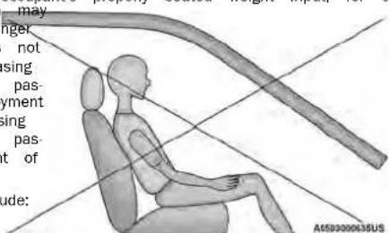
NotSeatedProperly
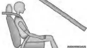
natural_image
Illustration of a person seated in a chair with a horizontal bar extending outward, no text or symbols present.SeatedProperly
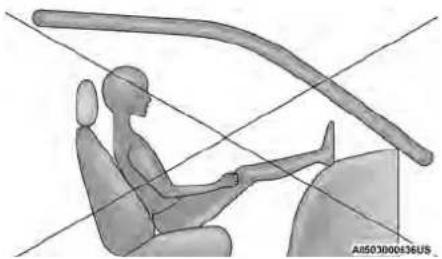
natural_image
Illustration of a person seated in a car with a curved arm overhead, no text or symbols presentNotSeatedProperly
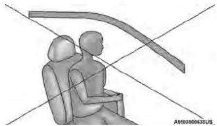
natural_image
Diagram of two human figures seated in a car seat, connected by curved lines (no text or symbols)NotSeatedProperly
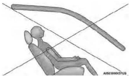
natural_image
3D rendered illustration of a seated human figure in a chair with curved arm, no text or symbols presentNotSeatedProperly
WARNING!
- If a child restraint system, child, small adult in the front passenger seat is severally, the occupant may provide an output of the OCS that is different from the occupantly seated weight input. This may result in injury or death in a collision.
- Always wear your seat belt and sit prop the seatback in an upright position, your against the seatback, sitting upright, facing ward, in the center of the seat, with y fortably on or near the floor.
- Do not carry or hold any objects (e.g., boxes, etc.) while seated in the front panel. Holding an object may provide an anal to the OCS that is different than properly seated weight input, which may be serious injury or death in a collision.
(Continued)
WARNING!
- Placing an object on the floor under the front passenger seat may prevent the OCS from working properly, which may result in serious injury or death in a collision. Do not place any objects on the floor under the front passenger seat.
The Air Bag Warning Light the instrument panel will turn on whenever the OCS is unable to classify front passenger seat status. A malfunction in the OCS may affect the operation of the air bag system. If the Air Bag Warning Lights not come on, or slays on after you start the vehicle, or it comes on you drive, take the vehicle to an authorized dealer for service immediately.
The passenger seat assembly contains critical OCS ted components that may affect the Passenger Advanced signnt to Air Bag inflation. In order for the OCS to prop ant'slasing the seated weight of a front seat passenger, in OCSlou components must function as designed. Do not make any modifications to the front passenger seat erly, components, assembly, or to the seat cover. If the se bad him cover, or cushion needs service for any reason, fo take the vehicle to an authorized dealer. Only FCA US our feet approved seat accessories may be used.
The following requirements must be strictly followed: • Not modify the front passenger seat assembly of larger components in any way. • Do not use prior or future model year seat covers • Cushions not designated by FCA US LLC for the specific model being repaired. Always use the correct seat cover and cushion specified for the vehicle.
- Do not replace the seat cover or cushion with an aftermarket seat cover or cushion.
- Do not add a secondary seat cover
- At no time should any Supplemental
tem (SRS) component or SRS related com fastener be modified or replaced with any except those which are approved by FCA
This vehicle is equipped with a Supplemental Driver in Knee Air Bag mounted in the instrument panel below the steering column and a Supplemental Passenger
SupplementalDriverAndFront
PassengerKneeAirBags
Knee Air Bag mounted in the instrument panel below the glove compartment. The Supplemental Knee Air Bags provide enhanced protection during a frontal impact by working together with the seat belts, preterm sioners, and front air bags.
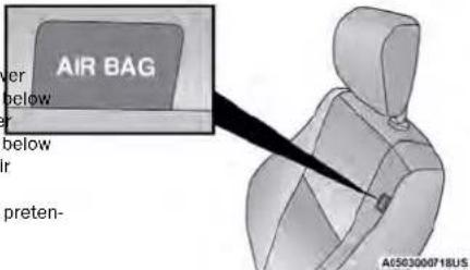
FrontSupplementalSeat-MountedSideAirBag
WARNING!
- Unapproved modifications or service procedure the passenger seat assembly, its related c nents, seat cover or cushion may inadvert change the air bag deployment in case of collision. This could result in death or se injury to the front passenger if the vehicle involved in a collision. A modified vehicle comply with required Federal Motor Vehicle Standards (FMVSS) and/or Canadian Motor Vehicle Safety Standards (CMVSS).
- If it is necessary to modify the air bag persons with disabilities, contact an author dealer.
SupplementalSideAirBags
SupplementalSeat-MountedSideAirBags(SABs)
maThisotvehicle is equipped with Supplemental Seat-SaMounted Side Air Bags (SABs).
Supplemental Seat-Mounted Side Air Bags (SABs)
located in the outboard side of the front seats systems fore marked with "SRS AIRBAG" or "AIRBAed label or on the seat trim on the outboard side seats.
The SABs may help reduce the risk of occupa
during certain side impacts, in addition to the
reduction potential provided by the seat belts a
When the SAB deploys, it opens the seam on the oil board side of the seatback's trim cover. The inflating SAB deploys through the seat seam into the space are between the occupant and the door. The SAB moves
a very high speed and with such a high force that could injure occupants if they are not seated or if items are positioned in the area where 6 inflates. Children are at an even greater risk of injury
KneelmpactBolsters
The Knee Impact Bolsters help protect the kneestructure driver and front passenger, and position the front occupants for improved interaction with the front air bags.
WARNING!
- Do not drill, cut, or tamper with the knee impact bolsters in any way.
- Do not mount any accessories to the knee impact bolsters such as alarm lights, stereos, citizen band radios, etc.
WARNING!
Do not use accessory seat covers or place objects between you and the Side Air Bags; the performance could be adversely affected and/or objects could be pushed into you, causing serious injury.
SupplementalSideAirBagInflatableCurtains (SABICs)
This vehicle is equipped with Supplemental Side Inflatable Curtains (SABICs).
Supplemental Side Air Bag Inflatable Curtains (SABICs are located above the side windows. The trim the SABICs is labeled "SRS AIRBAG" or "AIRBAG
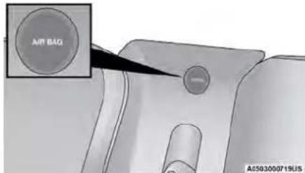
SupplementalSideAirBagInflatableCurtain(SABIC) LabelLocation
SABICs may help reduce the risk of head and ries to front and rear seat outboard occupants tain side impacts, in addition to the injury reduc potential provided by the seat belts and body s The SABIC deploys downward, covering the side v dows. An inflating SABIC pushes the outside edge headliner out of the way and covers the window SABICs inflate with enough force to injure occupa they are not belted and seated properly, or if positioned in the area where the SABICs inflate. dren are at an even greater risk of injury from ing air bag.
The SABICs may help reduce the risk of par-plete ejection of vehicle occupants through sid allows in certain side impact events.
WARNING!
• Do not mount equipment, or stack luggage other cargo up high enough to block the ment of the SABICs. The trim covering ab side windows where the SABIC and its ce path are located should remain free from obstructions.
- In order for the SABICs to work as intern install any accessory items in your vehicle could alter the roof. Do not add an after sunroof to your vehicle. Do not add roof require permanent attachments (bolts or scr for installation on the vehicle roof. Do not the roof of the vehicle for any reason.
SidelImpacts
The Side Air Bags are designed to activate in other impacts. The Occupant Restraint Controller (or the center determines whether the deployment of the Side Air Bags in a particular impact event is appropriate) on the severity and type of collision. The side sensors aid the ORC in determining the appropriate response to impact events. The system is calibrated by the deploy the Side Air Bags on the impact side vehicle during impacts that require Side Air Bags in a right-side protection. In side impacts, the Side Air Bags are deploy independently; a left side impact deploys Side Air Bags only and a right-side impact deploys right side Air Bags only. Vehicle damage by its a good indicator of whether or not Side Air Bags have deployed.
Thor Side- Air Bags will not deploy in all side collision including some collisions at certain angles, or some side collisions that do not impact the area of the passenger compartment. The Side Air Bags may deploy during angled or offset frontal collisions where the front air bags deploy.
Side Air Bags are a supplement to the seat belt enjoyaint system. Side Air Bags deploy in less time th: at takes to blink your eyes. payment
WARNING!
• Occupants, including children, who are up against whichor very close to Side Air Bags can be seriously injured or killed. Occupants, including children,cksshtraid never lean on or sleep against the door, ( ) side windows, or area where the side air bags drill inflate, even if they are in an infant or child restraint.
- Seat belts (and child restraints where appropriate) are necessary for your protection in all collisions. They also help keep you in position, away from an air inflating Side Air Bag. To get the best protection from the Side Air Bags, occupants must wear their seat belts properly and sit upright with their backs imposed in the seats. Children must be properly restrained in a child restraint or booster seat that is appropriate for the size of the child.
WARNING!
- Side Air Bags need room to inflate. Do against the door or window. Sit upright ter of the seat.
- Being too close to the Side Air Bags of ment could cause you to be severely in killed.
- Relying on the Side Air Bags alone could more severe injuries in a collision. The \$ Bags work with your seat belt to restrain early. In some collisions, Side Air Bags we at all. Always wear your seat belt even have Side Air Bags.
The SABICs may help reduce the risk of partial l'oryomoto have a collision which deploys the air bag: plete ejection of vehicle occupants through side winy or all of the following may occur: down in certain rollover or side impact events. The air bag material may sometimes cause abra-
AirBagSystemComponents
uringNOTEloy-
The Occupant Restraint Controller (ORC) monitors the internal circuits and interconnecting wiring associated with to electrical Air Bag System Components listed be
Side Air Occupant Restraint Controller (ORC) you prop- on't deploy Bag Warning Light
gh Steering Wheel and Column
- Instrument Panel
- Knee Impact Bolsters
- Driver and Front Passenger Air Bags
• Supplemental Side Air Bags
• Supplemental Knee Air Bags
designed and Side Impact Sensors
• Seat Belt Pretensioners
- Seat Track Position Sensors
mage Occupant Classification System
t_Side_Air
IfADeploymentOccurs
The front air bags are designed to deflate imme
NOTE:
Air bag covers may not be obvious in the i but they will open during air bag deployment.
RolloverEvents
Side Air Bags and seat belt pretensioners are to activate in certain rollover events. The Occi
Restraint Controller (ORC) determines whether de
ment in a particular rollover event is appropri
on the severity and type of collision. Vehicle
itself is not a good indicator of whether or
Bags and seat belt pretensioners should have deployed.
The Side Air Bags and seat belt pretensioners
deploy in all rollover events. The rollover sensing system
determines if a rollover event may be in progress and
whether deployment is appropriate. In the event front and/or side air bags will not deploy in vehicle experiences a rollover or near rollover events. This does not mean something is wrong and deployment is appropriate, the rollover sensing bag system.
system will deploy the side air bags and seat belt pre-
tensioners on both sides of the vehicle.
- The air bag material may sometimes cause abrasions and/or skin reddening to the occupants as that air bags deploy and unfold. The abrasions are similar to friction rope burns or those you might getting along a carpet or gymnasium floor. They are not caused by contact with chemicals. They are not permanent and normally heal quickly. However, if you haven't healed significantly within a few days, or if you have any blistering, see your doctor immediately.
- As the air bags deflate, you may see some smoke like particles. The particles are a normal by-product of the process that generates the non-toxic gas use for air bag inflation. These airborne particles may irritate the skin, eyes, nose, or throat. If you have skin or eye irritation, rinse the area with cool water. For nose or throat irritation, move to fresh air and then irritation continues, see your doctor. If these articles settle on your clothing, follow the gas manufacturer's instructions for cleaning.
Do not drive your vehicle after the air bags have deployed. If you are involved in another collision, the bags will not be in place to protect you.
WARNING!
Deployed air bags and seat belt pretensioners cannot protect you in another collision. Have the air bags, seat belt pretensioners, and the seat belt retractor assemblies replaced by an authorized dealer immediately. Also, have the Occupant Restraint Controller with the System serviced as well.
NOTE:
- Air bag covers may not be obvious in the interior, an accident, place the ignition in the SIO trim, but they will open during air bag deployment. The vehicle for fuel leaks in the engine compa
- After any collision, the vehicle should be taken and on the ground near the engine compartment authorized dealer immediately. fuel tank before resetting the system. If there
Interior position to avoid draining the battery. Carefully check
The vehicle for fuel leaks in the engine compa
EnhancedAccidentResponseSystem
In the event of an impact, if the communication following the procedure described below. If you work remains intact, and the power remains intact any doubt, contact an authorized dealer. depending on the nature of the event, the ORC will determine whether to have the Enhanced Accident Response System perform the following functions: ResetProcedure
- Cut off fuel to the engine (if equipped).
- Cut off battery power to the electric motor tem functions after an event, the ignition switch (if equipped). be changed from ignition START or ON/RUN to
- Flash hazard lights as long as the battery haOFFpowarefully check the vehicle for fuel leaks
- Turn on the interior lights, which remain on angling compartment and on the ground near the as the battery has power or for 15 minutes engine compartment and fuel tank before resetting intervention of the Enhanced Accident Response system and starting the engine.
In order to reset the Enhanced Accident Response functions after an event, the ignition switch be changed from ignition START or ON/RUN to
aOFFpow carefully check the vehicle for fuel leaks
as gilong compartment and on the ground near the engine thompartment and fuel tank before resetting system and starting the engine.
System. - Unlock the power door locks. After an accident, if the vehicle will not start forming the reset procedure, the vehicle must be Your vehicle may also be designed to perform any or authorized dealer to be inspected and to these other functions in response to the Enhanced Accident Response System reset. dent Response System:
- Turn off the Fuel Filter Heater, Turn off the HVAC Blower Motor, Close the HVAC Circulation Door
- Cut off battery power to the:
○ Engine
○ Electric Motor (if equipped)
Electric power steering
Brake booster
○ Electric park brake
○ Automatic transmission gear selector
○ Horn
○ Front wiper
NOTE:
After an accident, place the ignition in the STOP (OFF)
and on the ground near the engine compartment fuel tank before resetting the system. If there fuel leaks or damage to the vehicle electrical (e.g. headlights) after an accident, reset the sy
following the procedure described below. If you
any doubt, contact an authorized dealer.
will
tEnhancedAccidentResponseSystem
ResetProcedure
After an accident, if the vehicle will not start
forming the reset procedure, the vehicle must be
any and authorized dealer to be inspected and to
eEnhanced Accident Response System reset.
The Ground Truth image displays a single, solid horizontal line. According to Rule 2 (UNDERSCORE & LINE RULES), this is a stylistic or background line, not a placeholder underscore. Therefore, the OCR result must ignore it and output nothing or only meaningful text. The provided OCR content is "____", which consists of four underscores. This is an incorrect interpretation of the line as a placeholder, violating the rule that stylistic lines must be ignored. The OCR has hallucinated underscores where none should exist based on the GT's visual context. Hence, the OCR result is inconsistent with the Ground Truth.
[Non-Text]
[Non-Text]
[Non-Text]
[Non-Text]
MaintainingYourAirBagSystem
| check | WARNING! |
| tment |
Modifications to any part of the air bag system are could cause it to fail when you need it. You could be injured if the air bag system is not there to test by you. Do not modify the components or wiring, including adding any kind of badges or stickers to the steering wheel hub trim cover or the upper passenger side of the instrument panel. Do not modify the front fascia/bumper, vehicle body structure, or add aftermarket side steps or running boards.
It's dangerous to try to repair any part of the m bag system yourself. Be sure to tell anyone who ignooks on your vehicle that it has an air bag syst
Do not attempt to modify any part of your air bag system. The air bag may inflate accidentally or may be function properly if modifications are made. Take your vehicle to an authorized dealer for any after air bag system service. If your seat, including your
e followed cover and cushion, needs to be serviced in have way (including removal or loosening/tightening of seat attachment bolts), take the vehicle to an authorized dealer. Only manufacturer approved seat accessories may be used. If it is necessary to modify the air bag system for persons with disabilities, contact an authorized dealer.
EventDataRecorder(EDR)
CHILD RESTRAINTS
NOTE:
This vehicle is equipped with an event data record. Everyone in your vehicle needs to be buckled up for additional information, refer to (EDR). The main purpose of an EDR is to record times, including babies and children. Every state in http://www.nhtsa.gov/parents-and-caregivers or tain crash or near crash-like situations, such as United States, and every Canadian province, requires call: 1-888-327-4236 bag deployment or hitting a road obstacle, data that small children ride in proper restraint systems. This assist in understanding how a vehicle's systems be the law, and you can be prosecuted for ignoring it formed. The EDR is designed to record data related to vehicles dynamics and safety systems for a short period led up in a rear seat, if available. According to on-car-seat-safety of time, typically 30 seconds or less. The EDR in this statistics, children are safer when properly restrained in vehicle is designed to record such data as: the rear seats rather than in the front
- How various systems in your vehicle were operating;
- Whether or not the driver and passenger safe belts were buckled/fastened;
- How far (if at all) the driver was depressing accelerator and/or brake pedal; and,
- How fast the vehicle was traveling. These data can help provide a better understand the circumstances in which crashes and injuries
WARNING!
In thea collision, an unrestrained child can become a projectile inside the vehicle. The force required to hold even an infant on your lap could become so great that you could not hold the child, no matter how strong you are. The child and others could be badly injured or killed. Any child riding in your vehicle should be in a proper restraint for the child's size.
NOTE:
EDR data are recorded by your vehicle only if a non-trivial crash situation occurs; no data are recorded by the EDR under normal driving conditions and no person from newborn size to the child almost large sonal data (e.g., name, gender, age, and crash environment) for an adult safety belt. Always check the child are recorded. However, other parties, such as law enforcement, could combine the EDR data with the type of personally identifying data routinely acquired during instructions and warnings in the child restraint Owner's manual and on all the labels attached to the child crash investigation.
To read data recorded by an EDR, special equipment is required, and access to the vehicle or the EDR. Before buying any restraint system, make sure that it needed. In addition to the vehicle manufacturer, has a label certifying that it meets all applicable Safety parties, such as law enforcement, that have the special standards. You should also make sure that you can install it in the vehicle where you will use it. access to the vehicle or the EDR.
SummaryOfRecommendationsForRestrainingChildrenInVehicles
| ChildSize,Height,WeightOrAgeRecommendedType | OfChildRestraint | |
| Infants and Toddlers | Children who are two years old or younger and who have the height or weight limits of their child restraint | Either not an reared Carrier or a Convertible Child Restraint, ward in a rear seat of the vehicle |
| Small Children | Children who are at least two years old or who have height or weight limit of their rear-facing child restraint | Forward-facing Child Restraint with a five-point Harness, ward in a rear seat of the vehicle |
| Larger Children | Children who have outgrown their forward-facing child restraint are too small to properly fit the vehicle's seat belt | Positioning Booster Seat and the vehicle seat belt, rear seat of the vehicle |
| Children Too Large for Children Restraints | Children 12 years old or younger, who have outgrown weight limit of their booster seat | the height or Vehicle Seat Belt, seated in a rear seat of the vehicle |
facing rea
acing for-
seated in
InfantAndChildRestraints
Safety experts recommend that children ride rear-f in the vehicle until they are two years old or reach either the height or weight limit of their facing child restraint. Two types of child restraints be used rear-facing: infant carriers and convertible seats.
The infant carrier is only used rear-facing in the It is recommended for children from birth until t reach the weight or height limit of the infant o Convertible child seats can be used either rear-fa forward-facing in the vehicle. Convertible child seat
often have a higher weight limit in the rear-facing direction than infant carriers do, so they can be used rear-
facing by children who have outgrown their infant car-
rier but are still less than at least two years old.
Children should remain rear-facing until they reach the
highest weight or height allowed by their convertible
child seat.
WARNING!
Until Netthey place a rear-facing child restraint in rear an air bag. A deploying passenger front cause death or serious injury to a child chunger, including a child in a rear-facing restraint.
- vehicle install a rear-facing child restraint in the heyfront seat of a vehicle. Only use a rear-facing child restraint in the rear seat. If the vehicle does not cing have a rear seat, do not transport a rear-facing child restraint in that vehicle.
WARNING!
Do not install a rear-facing car seat using port leg in this vehicle. The floor of this designed to manage the crash forces of the car seat. In a crash, the support leg may as it was designed by the car seat manu your child may be more severely injured as
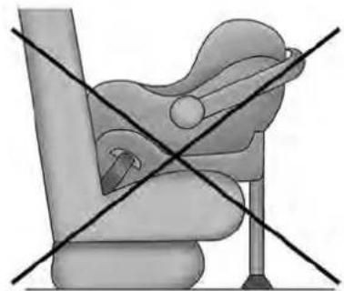
natural_image
Medical illustration of a seated car seat with cross-sectional lines indicating pressure or measurement (no text or symbols present)OlderChildrenAndChildRestraints
Children who are two years old or who have their rear-facing convertible child seat can ride facing in the vehicle. Forward-facing child seats convertible child seats used in the forward-facintion are for children who are over two years have outgrown the rear-facing weight or height
their rear-facing convertible child seat. Children remain in a forward-facing child seat with a as long as possible, up to the highest weigh allowed by the child seat.
s style children whose weight or height is above the against the seatback, should use the seat belt in a noforromotioning limit for the child seat should use seat. Butse this simple 5-step test to decide whether the act positioning booster seat until the vehicle's seat behind from use the vehicle's seat belt alone:
a properly. If the child cannot sit with knees bent 1. over the vehicle's seat cushion while the child's back is against the child sit all the way back against the b vehicle's seat.
the seatback, they should use a belt-positioning booster seat. The child and belt-positioning booster 2. Do the child's knees bend comfortably over the front of the vehicle seat while the child is still sitting at the way back?
WARNING!
- Improper installation can lead to failure of infant or child restraint. It could come to collision. The child could be badly injured. Follow the child restraint manufacturer's daily exactly when installing an infant or child.
- After a child restraint is installed in the not move the vehicle seat forward or around because it can loosen the child restraint conditions. Remove the child restraint before the vehicle seat position. When the vehicle has been adjusted, reinstall the child rest
-
When your child restraint is not in use, the vehicle with the seat belt or LATCH ages, or remove it from the vehicle. Do outgrown in the vehicle. In a sudden stop forward—could strike the occupants or seatbacks and cause serious personal injury.
-
Does the shoulder belt cross the child's shoulder between the neck and arm?
an4. Is the lap part of the belt as low as possible, lose in ing the child's thighs and not the stomach?
or skill can the child stay seated like this for the whole ections If the answer to any of these questions was
the child still needs to use a booster seat vehicle. If the child is using the lap/shoulder belt, forward beat belt fit periodically and make sure the seat belt attachuckle is latched. A child's squirming or slouching can adjust the belt out of position. If the shoulder belt ce seats the face or neck, move the child closer to the mainter of the vehicle, or use a booster seat to position secure seat it belt on the child correctly.
anchor-
not
leave it
WARNING!
and Never allow a child to put the shoulder belt under arm or behind their back. In a crash, the shoulder belt will not protect a child properly, which may result in serious injury or death. A child must always wear both the lap and shoulder portions of the seat belt correctly.
RecommendationsForAttachingChildRestraints
| RestraintTypeCombinedWeightoftheChild+ChildRestraint | UseAnyAttachmentMethodShownWithAn“X”Below | ||||
| LATCH-LowerAnchors Only | SeatBeltOnlyLATCH-LowerAnchors+TopTetherAnchor | SeatBelt+TopTether Anchor | |||
| Rear-Facing Child Restraint | Up to 65 lb (29.5 kg) X X | ||||
| Rear-Facing Child Restraint | More than 65 lb (29.5 kg) X | ||||
| Forward-Facing Child Restraint | Up to 65 lb (29.5 kg) XX | ||||
| Forward-Facing Child Restraint | More than 65 lb (29.5 kg) X | ||||
LowerAnchorsAndTethersForChildren (LATCH)RestraintSystem
022668173
LATCHLabel
Your vehicle is equipped with the child restraint LATCH Positions For Installing Child age system called LATCH, which stands for Lower Anchors and Tethers for Children. The LATCH system Restraints In This Vehicle
has three vehicle anchor points for installing LATCH-equipped child seats. There are two lower anchorages
located at the back of the seat cushion where it meets
the seatback and one top tether anchorage located
behind the seating position. These anchorages are
used to install LATCH-equipped child seats without using the vehicle's seat, bolts. Same seating positions
using the vehicle's seat belts. Some seating positions may have a top tether anchorage, but no lower anchor-
ages. In these seating positions, the seat belt must be
used with the top tether anchorage to install the
restraint. Please see the following table for more
information
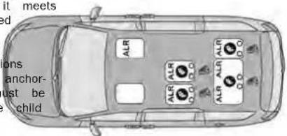
A0503001135US
SevenPassengerBenchSeatLATCHPositions
Lower Anchorage Symbol (Two Anchorage Per Seating Position)
Top Tether Anchorage Symbol
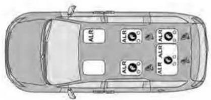
A850001136US
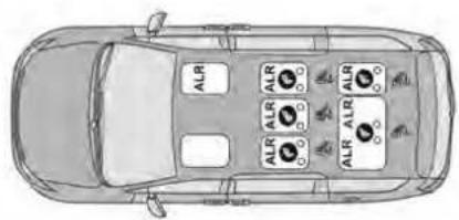
A0503001137US
SevenPassengerStow'nGoSeatingLATCHPositions
EightPassengerLATCHPositions
Lower Anchorage Symbol (Two Anchorage Seating Position)
Top Tether Anchorage Symbol
Per Lower Anchorage Symbol (Two Anchorage Per Seating Position)
Top Tether Anchorage Symbol
FrequentlyAskedQuestionsAboutInstallingChildRestraintsWithLATCH
| What is the weight limit (child's weight + weight of the child restraint) for using the LATCH anchorage system to attach the child restraint? (29.5 kg) | 65 lb | Use the LATCH anchorage system until the combined weight of the child and the child restraint is 65 lb (29.5 kg). Use the seat I tether anchor Instead of the LATCH system once the combined weight is more than 65 lb (29.5 kg). |
| Can the LATCH anchorages and the seat belt be used attach a rear-facing or forward-facing child restraint? | together to No | Do not use the seat belt when you use the LATCH anchorage s to attach a rear-facing or forward-facing child restraint. Booster seats may be attached to the LATCH anchorages if allowe by the booster seat manufacturer. See your booster seat owner's manual for more information. |
| Can two child restraints be attached using a common anchorage? | ower LATCH No | Never "share" a LATCH anchorage with two or more child restraint If the center position does not have dedicated LATCH lower anchages, use the seat belt to install a child seat in the center po next to a child seat using the LATCH anchorages in an outboard position. |
| FrequentlyAskedQuestionsAboutInstallingChildRestraintsWithLATCH | ||
| Can the rear-facing child restraint touch the back of the senger seat? | front pas- Yes | The child seat may touch the back of the front passenger seat child restraint manufacturer also allows contact. See your child restraint owner's manual for more information. |
| Can the rear head restraints be removed? Yes | The 2nd row head restraints on bench and the center head rest in the 8 passenger vehicle can be removed if they interfere with installation of the child restraint. 2nd row Stow 'n Go head restr are not removable. The 3rd row center head restraint is removable all vehicles, but the 3rd row outboard head restraints are not re able page 35. | |
NOTE:
If the folding, non-adjustable head restraint interfere with the installation of the child restraint, the h restraint may be folded and the child seat insta front of it.
WARNING!
Always make sure the head restraint is in its position when the seat is to be used by an who is not in a child restraint. Sitting in a the head restraint in its lowered position could in serious injury or death in a collision.
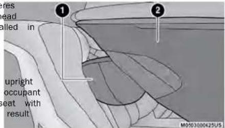
CarSeatWithHeadRestraintFolded
1 - Folded Headrest
2 - Child Restraint
LocatingTheLATCHAnchorage

The lower anchorages are round bars are found at the rear of the seat where it meets the seatback, below anchorage symbols on the seatback. are just visible when you lean into the rear seat to install the child restraint. You will easily feel them run your finger along the gap between the seatback and seat cushion.
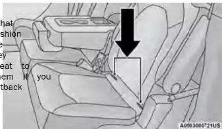
LATCHAnchorage(SecondRowAnchorageShown) EightPassengerSeating
the center of the 60% seat for either the center or outboard seating position. All tether anchorages are located on the back of the seat, near the floor.
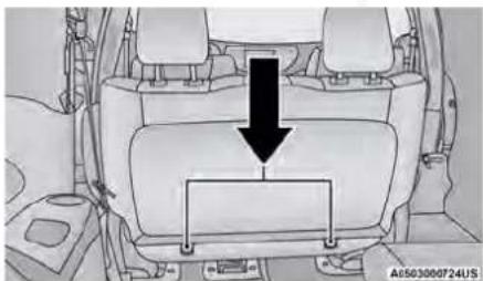
natural_image
Interior view of a car showing seat, dashboard, and rear seats with a black arrow pointing to the dashboard (no text or symbols present)TetherStrapAnchorage(SecondRowBenchAnchorage Shown)
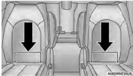
natural_image
Interior view of a vehicle showing two compartments with downward arrows indicating movement or force (no text or symbols present)LATCHAnchorage(SecondRowAnchorageShown) SevenPassengerStow'nGoSeating
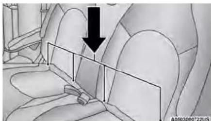
natural_image
Interior view of a car seatbelt with a black arrow pointing to the seat (no text or symbols visible)LATCHAnchorage(SecondRowBenchAnchorage Shown)SevenPassengerBenchSeating
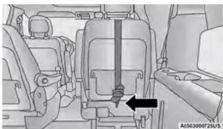
natural_image
Interior view of a vehicle seat assembly with a black arrow pointing to a component (no text or symbols visible)TetherStrapAnchorage(SecondRowSevenPassenger Stow'nGoAnchorageShown)
LocatingTheUpperTetherAnchorage

There are tether strap anchorages located behind all second row seating positions. The third row has a tether anchor on the 40% seat for the right outboard position and in
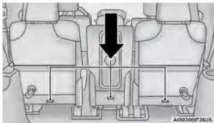
natural_image
Technical diagram of a vehicle rear view showing structural components and a black arrow indicating a directional flow or force (no text or symbols present)TetherStrapAnchorages(SecondRowEightPassenger AnchorageShown)
equipped with a tether strap. The tether strap a hook at the end to attach to the top tether and a way to tighten the strap after it is at anchorage.
CenterSeatLATCH
This vehicle has 4 lower LATCH anchorages in row, rear seat. Anchorages A and B are used right outboard position behind the front passenger. Anchorages C and D are used for the center position (2). The left outboard position (3) does have lower anchorages. Do not install a child
using anchorages B and C. This is not a LAT in your vehicle.
| will haveer anchorage | WARNING! |
| tached to the |
| Use anchorages C and D to install a LATCH-compatible child restraint in the center seating position (2). Do not install a LATCH-compatible child restraint using anchorages B and C. This is then nothing LATCH-compatible position in your vehicle. for the Never use the same lower anchorage to attach more than one child restraint. Please see seating page 154 for typical installation instructions. |
restraint Always follow the direction of the child restraint that is better when installing your child restraint. Not all child restraints system will be installed as described here.

TetherStrapAnchorage(ThirdRow60/40Anchorage Shown)
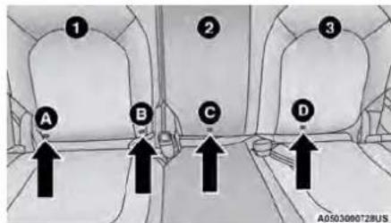
ThirdRowCenterSeatLATCHPositions
ToInstallALATCH-CompatibleChild Restraint
If the selected seating position has a Switchable Automatic Locking Retractor (ALR) seat belt, stow the seat belt, following the instructions below. See page 155 to check what type of seat belt each seating position has.
- Loosen the adjusters on the lower straps and on tether strap of the child seat so that you can me easily attach the hooks or connectors to the vehicle anchorages.
- Place the child seat between the lower anchorages
LATCH-compatible child restraint systems will be equipped with a rigid bar or a flexible strap side. Each will have a hook or connector to the lower anchorage and a way to tighten the tion to the anchorage. Forward-facing child rest and some rear-facing child restraints will also
If a child restraint installed in the center position for both that seating position. If the second row seat can be on each seat belt webbing or buckle for the outboard bposreclined, you may recline the seat and/or raise attachment to do not use that outboard position. If a child's seat restraint (if adjustable) to get a better fill attachment to the center position blocks the outboard LATCH anches rear seat can be moved forward and rearward on each seat belt, do not install a child seat in that outboard positions.
the vehicle, you may wish to move it to position to make room for the child seat. also move the front seat forward to allow for the child seat.
- Attach the lower hooks or connectors of the restraint to the lower anchorages in the select seating position.
- If the child restraint has a tether strap, con the top tether anchorage. Page 158 for directions to attach a tether anchor.
- Tighten all of the straps as you push the restraint rearward and downward into the seat. Remove slack in the straps according to the restraint manufacturer's instructions.
- Test that the child restraint is installed tightly pulling back and forth on the child seat at path. It should not move more than 1 inch (25.4 mm) in any direction.
| rear-most u may | WARNING! |
| #e roomImproper installation of a child restraint to LATCH anchorages can lead to failure of constraint. The child could be badly injured. tedFollow the child restraint manufacturer's die exactly when installing an infant or child | |
| Child restraint anchorages are designed to nect it to stand only those loads imposed by correct child restraints. Under no circumstances are to be used for adult seat belts, harnessse child attaching other items or equipment to the | |
InstallingChildRestraintsUsingThe VehicleSeatBelt
the belt restraint systems are designed to be secured vehicle seats by lap belts or the lap belt portion lap/shoulder belt.
bing retract back into the retractor. If it is locked, the ALR will make a clicking noise while the webbing is pulled back into the retractor.
the See the "Automatic Locking Mode" description or 135 for additional Information on ALR. ectionase see the table below and the following sections restrent, more information.
with- ly-fitted the Lap/ShoulderBeltSystemsFor InstallingChildRestraintsInThisVehicle
, or to vehicle.
HowToStowAnUnusedSwitchable-ALR (ALR)SeatBelt:
When using the LATCH attaching system to insta child restraint, stow all ALR seat belts that are used by other occupants or being used to secure restraints. An unused belt could injure a child in play with it and accidentally lock the seat belt Before installing a child restraint using the LATCH
tem, buckle the seat belt behind the child restraint and out of the child's reach. If the buckled seat belt equipped with a Switchable Automatic Locking Retra- feres with the child restraint installation, instead of (ALR) that is designed to keep the lap portion of the buckling it behind the child restraint, route the seat belt tight around the child restraint so that it is not through the child restraint belt path and then buckle it. Do not lock the seat belt. Remind all children be "Switched" into a locked mode by pulling all of the vehicle that the seat belts are not toys and that they wedding out of the retractor and then letting the web- should not play with them.
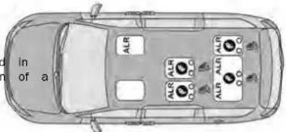
A05030011X5U8
secure a
restraints
SevenPassengerBenchSeatAutomaticLocking Retractor(ALR)Locations
ections
restrain
- Switchable Automatic Locking Retractor Top Tether Anchorage Symbol
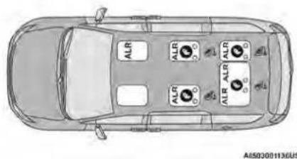
natural_image
Top-down line drawing of a car showing four ALR (Aluminum Air Lines) sensors on the roof, with no text or symbols present.SevenPassengerStow'nGoSeatIngAutomaticLocking Retractor(ALR)Locations
ALR — Switchable Automatic Locking Retractor Top Tether Anchorage Symbol
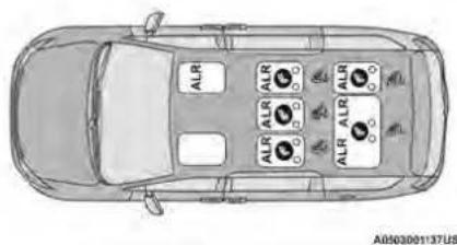
EightPassengerAutomaticLockingRetractor(ALR) Locations
ALR — Switchable Automatic Locking Retractor Top Tether Anchorage Symbol
FrequentlyAskedQuestions
| What is the weight limit (child's weight + weight of the child restraint) for using the Tether Anchor with the seat belt to attach a weight forward-of the Child re- facing child restraint? | Weight forward-of the Child Re- forward-facing child restraint, up to the recommended weight limit - the child restraint. | Always use the tether anchor when using the seat belt to install re- start-facing child restraint, up to the recommended weight limit - the child restraint. |
| Can the rear-facing child restraint touch the back of the front pas- Yes passenger seat? | Contact between the front passenger seat and the child allowed, if the child restraint manufacturer also allows contact. | |
| Can the rear head restraints be removed? Yes | The 2nd row head restraints on bench and the center head rest in the 8 passenger vehicle can be removed if they interfere with installation of the child restraint. 2nd row Slow 'n Go head restr are not removable. The 3rd row center head restraint is removable all vehicles, but the 3rd row outboard head restraints are not re able page 35. | |
| Can the buckle stalk be twisted to tighten the seat belt against the No belt path of the child restraint? | Do not twist the buckle stalk in a seating position with an ALR retractor. |
NOTE:
If the folding, non-adjustable head restraint inte with the installation of the child restraint, the restraint may be folded and the child seat in front of it.
WARNING!
Always make sure the head restraint is in its position when the seat is to be used by an who is not in a child restraint. Sitting in a 5 the head restraint in its lowered position could in serious injury or death in a collision.
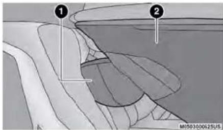
CarSeatWithHeadRestraintFolded
1 - Folded Headrest
2 - Child Restraint
InstallingAChildRestraintWithA
SwitchableAutomaticLockingRetractor
head (ALR):
Child restraint systems are designed to be secured vehicle seats by lap belts or the lap belt portion lap/shoulder belt.
upright occupant WARNING!
-atlimpidper installation or failure to properly reebild restraint can lead to failure of the The child could be badly injured or killed
- Follow the child restraint manufacturer's die exactly when installing an infant or child
bing to retract back into the retractor. As the web-bing retracts, you will hear a clicking sound. This means the seat belt is now in the Automatic Lock mode.
secured by to pull the webbing out of the retractor. If it is portion of a locked, you should not be able to pull out any webbing. If the retractor is not locked, repeat step 5.
- Finally, pull up on any excess webbing to tighten lap portion around the child restraint while you pus secure the child restraint rearward and downward into the restraint vehicle seat.
- If the child restraint has a top tether strap and resections seating position has a top tether anchorage, con-restrainect the tether strap to the anchorage and tighten the tether strap. See page 158 for directions to attach a tether anchor.
SeatBeltParkStitch—IfEquipped
Test may that the child restraint is installed tightly by pulling back and forth on the child seat path be should not move more than 1 in (254 mm) in any direction.
to make seat belt system will loosen with time, so check move before occasionally, and pull it light if necessary.
child seat.
1. Place the child seat in the center of the seating position. If the second row seat can be reclined, 9 yo test may that the child restraint is installed tightly by recline the seat and/or raise the head restraint pulling back and forth on the child seat adjustable) to get a better fit. If the rear seat path should not move more than 1 in moved forward and rearward in the vehicle, you (254 mm) in any direction.
wish to move it to its rear-most position to make seat belt system will loosen with time, so check room for the child seat. You may also move before occasionally, and pull it light if necessary.
seat forward to allow more room for the child seat.
1. Place the child seat in the center of the seating position. If the second row seat can be reclined, 9 yo test may that the child restraint is installed tightly by recline the seat and/or raise the head restraint pulling back and forth on the child seat adjustable) to get a better fit. If the rear seat path should not move more than 1 in moved forward and rearward in the vehicle, you (254 mm) in any direction.
wish to move it to its rear-most position to make seat belt system will loosen with time, so check room for the child seat. You may also move before occasionally, and pull it light if necessary.
seat forward to allow more room for the child seat.
1. Place the child seat in the center of the seating position. If the second row seat can be reclined, 9 yo test may that the child restraint is installed tightly by recline the seat and/or raise the head restraint pulling back and forth on the child seat adjustable) to get a better fit. If the rear seat path should not move more than 1 in moved forward and rearward in the vehicle, you (254 mm) in any direction.
wish to move it to its rear-most position to make seat belt system will loosen with time, so check room for the child seat. You may also move before occasionally, and pull it light if necessary.
seat forward to allow more room for the child seat.
1. Place the child seat in the center of the seating position. If the second row seat can be reclined, 9 yo test may that the child restraint is installed tightly by recline the seat and/or raise the head restraint pulling back and forth on the child seat adjustable) to get a better fit. If the rear seat path should not move more than 1 in moved forward and rearward in the vehicle, you (254 mm) in any direction.
wish to move it to its rear-most position to make seat belt system will loosen with time, so check room for the child seat. You may also move before occasionally, and pull it light if necessary.
seat forward to allow more room for the child seat.
1. Place the child seat in the center of the seating position. If the second row seat can be reclined, 9 yo test may that the child restraint is installed tightly by recline the seat and/or raise the head restraint pulling back and forth on the child seat adjustable) to get a better fit. If the rear seat path should not move more than 1 in moved forward and rearward in the vehicle, you (254 mm) in any direction.
wish to move it to its rear-most position to make seat belt system will loosen with time, so check room for the child seat. You may also move before occasionally, and pull it light if necessary.
seat forward to allow more room for the child seat.
2. Pull enough of the seat belt webbing from the retractor to pass it through the belt path of The reaid outboard seat belts may be equipped with a restraint. Do not twist the belt webbing in the parbelstitch to raise the latch plate for easier access path. SeatBeltParkStitch—IfEquipped occupants. If the park stitch interferes with the tight
2. Pull enough of the seat belt webbing from the retractor to pass it through the belt path of The reaid outboard seat belts may be equipped with a restraint. Do not twist the belt webbing in the parbelstitch to raise the latch plate for easier access path. SeatBeltParkStitch—IfEquipped occupants. If the park stitch interferes with the tight
3. Slide the latch plate into the buckle until you hear a installation of a child restraint, slide the latch plate of "click." The stitching to shorten the lap portion of the belt a install the car seat following the stops above. When t
4. Pull on the webbing to make the lap portionartightat is removed from the vehicle, slide the latch against the child seat. plate above the park stitch to enable occupants to la
5. To lock the seat belt, pull down on the shoulder part of the belt until you have pulled all the seat belt webbing out of the retractor. Then, allow the web-
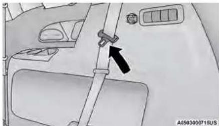
SeatBeltParkStitchLocation
If the park stitch interferes with the lock-off feature, the child restraint, do not use the lock-off feature. Instead, switch the seat belt to the locking mode, described in the steps above or move the car se different seating position.
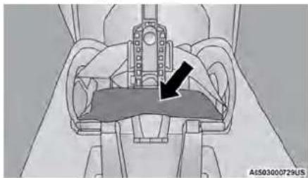
natural_image
Mechanical assembly diagram showing hands holding a component with a black arrow indicating a specific part (no text or symbols present)SeatBeltParkStitch
InstallingChildRestraintsUsingtheTop TetherAnchorage
WARNING!
Do not attach a tether strap for a rear-face to any location in front of the car seat, seat frame or a tether anchorage. Only at least tether strap of a rear-facing car seat to anchorage that is approved for that seating located behind the top of the vehicle seat. page 150 for the location of approved anchorages in your vehicle.
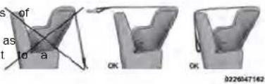
SecondRowTetherAttachment
- Look behind the seating position where you plan to install the child restraint to find the tether anchorage. You may need to move the seat forward, provide better access to the tether anchorage. If it is no top tether anchorage for that seating point, move the child restraint to another position in vehicle if one is available.
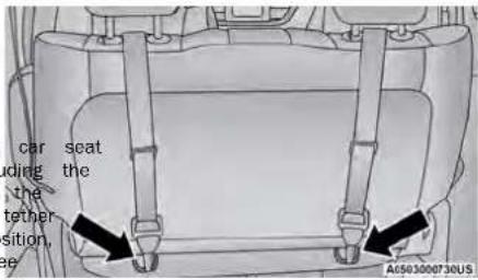
TopTetherAnchorageLocations—2ndRowBench
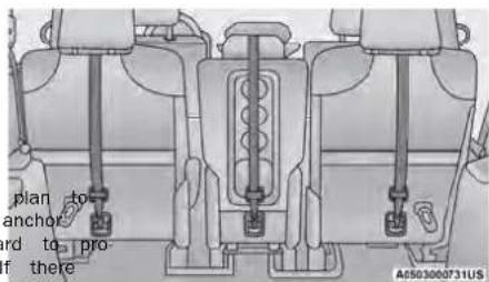
TopTetherAnchorageLocations—2ndRowEight Passenger
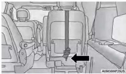
natural_image
Interior view of a vehicle seat assembly with a black arrow pointing to the seat (no text or symbols visible)TopTetherAnchorageLocation—2ndRowSeven PassengerStow'nGoAnchorage
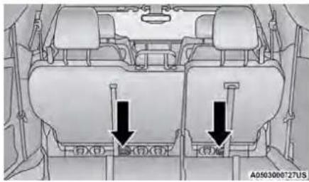
natural_image
Interior view of a vehicle showing two seats with directional arrows indicating movement or positioning (no text or symbols present)TopTetherAnchorageLocations—3rdRow
To connect the tether strap hook to the tether ancho age for either seating position on the 60% third row seat:
- Route the tether strap to provide the most direct path for the strap between the anchor and the ch seat.
- If the car seat is in the center, raise the center restraint and route the tether strap around the inboard (left) side of the head restraint support posts, as shown in the diagram.
- Attach the tether strap hook of the child restraint the top tether anchorage as shown in the diagram.
- Remove slack in the tether strap according to the child restraint manufacturer's instructions.
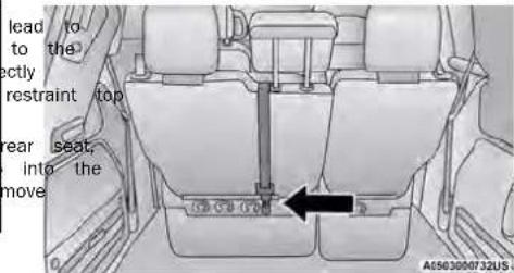
CenterTetherAttachment-3rdRow
| direct | WARNING! |
| the child | Incorrectly anchored tether strap could increase head motion and possible injury where. Use only the anchorage position dirad behind the child seat to secure a child possible tether strap. |
| ●If your vehicle is equipped with a split t. make sure the tether strap does not slip stra#ening between the seatbacks as you reag slock in the strap. | |
- Route the tether strap to provide the most path for the strap between the anchor and seat. If your vehicle is equipped with adjustable head restraints, raise the head restraint, and possible, route the tether strap under the head restraint and between the two posts. If not lower the head restraint and pass the tether around the outboard side of the head restraint
- Attach the tether strap hook of the child re the top tether anchorage as shown in the d
- Remove slack in the tether strap according child restraint manufacturer's instructions.
to the
ThirdRowTetherAttachment
The tether anchorage found on the back of the 60% seat in the third row may be used by either the left outboard or the center seating position. Only tether one child restraint to the tether anchorage at a time.
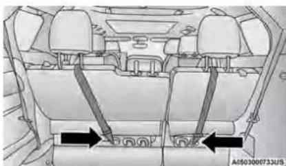
natural_image
Interior view of a car dashboard with seatbelt and rearview (no visible text or symbols)OutboardTetherAttachments-3rdRow
WARNING!
Do not connect the tether strap for more the child restraint to the tether anchorage on the seat in the third row. This anchorage is into one child restraint at a time.
SAFETYTIPS
TRANSPORTING PASSENGERS
NEVER TRANSPORT PASSENGERS IN THE CARGO
WARNING!
- Do not leave children or animals inside park vehicles in hot weather. Interior heat buildup cause serious injury or death.
- It is extremely dangerous to ride in a cargo inside or outside of a vehicle. In a collision, riding in these areas are more likely to be injured or killed.
(Continued)
WARNING!
- Do not allow people to ride in any area vehicle that is not equipped with seats a belts.
- Be sure everyone in your vehicle is in using a seat belt properly.
TRANSPORTING PETS
Air Bags deploying in the front seat could have pet. An unrestrained pet will be thrown about bly injured, or injure a passenger during panic or in a collision.
Pets should be restrained in the rear seat (if ironpet harnesses or pet carriers that are secat belts.
^ed CONNECTED VEHICLES
Privacy of any wireless and wired communication not be ensured. Third parties may unlawfully in information and private communications without consent. For further information, refer to "Data tion & Privacy" in your Uconnect Radio Instruct Manual or "Onboard Diagnostic System (OBD II) security" page 70.
WARNING!
lay is not possible to know or to predict a sible outcomes if your vehicle's systems are breached. It may be possible that vehicle s peaking safety related systems, could be in saridosity of vehicle control could occur that an accident involving serious injury or death
SAFETY CHECKS YOU SHOULD MAKE INSIDE THE VEHICLE
seat SeatBelts
shape and the seat belt system periodically, checking for cuts, frays, and loose parts. Damaged parts must be replaced immediately. Do not disassemble or modify the system.
If your vehicle is involved in a collision, or if you have questions regarding seat belt or retractor conditions, make your vehicle to an authorized FCA dealer or authorized FCA Certified Collision Care Program facility for braking inspection.
AirBagWarningLight

The Air Bag Warning Light will turn on for four to eight seconds as a bulb check when the ignition switch is first placed in the ON/RUN mode. If the light is either not on
Defroster
of the pos Check operation by selecting the defrost mode and place the blower control on high speed. You should be able to feel the air directed against the windshield. S and authorized dealer for service if your defroster is in result in verable
FloorMatSafetyInformation
Always use floor mats designed to fit your vehicle use a floor mat that does not interfere with the tension of the accelerator, brake or clutch pedals. a floor mat that is securely attached using the fasteners so it cannot slip out of position and with the accelerator, brake or clutch pedals or safe operation of your vehicle in other ways.
WARNING!
An improperly attached, damaged, folded, or stood floor mat, or damaged floor mat fasteners may your floor mat to interfere with the accelerator, or clutch pedals and cause a loss of vehicle. To prevent SERIOUS INJURY or DEATH:
- ALWAYS securely attach your floor mat fasteners. DO NOT install your floor mat upside down your floor mat over. Lightly pull the floor mat is secured using the floor mat fasteners regular basis.
- ALWAYS REMOVE THE EXISTING FLAM MAT FROM THE VEHICLE before I have any other floor mat. NEVER install stack an additional floor mat on an existing floor mat.
- ONLY install floor mats designed to fit your NEVER install a floor mat that cannot be pr attached and secured to your vehicle. If a f needs to be replaced, only use a FCA appro floor mat for the specific make, model, and your vehicle.


(Continued)
WARNING!
Only use the driver's side floor mat on the operator floor area. To check for interference, only use vehicle properly parked with the engine of floor that depress the accelerator, the brake, and the interference pedal (if present) to check for interference in floor mat interferes with the operation of pedal, or is not secure to the floor, rest floor mat from the vehicle and place the in your trunk.
• ONLY use the passenger's side floor mat
cause
passenger's side floor area.
●bRAWAYS make sure objects cannot fall or control. driver's side floor area when the veh moving. Objects can become trapped under erator, brake, or clutch pedals and could loss of vehicle control.
- NEVER place any objects under the floor towels, keys, etc.). These objects could change position of the floor mat and may cause ence with the accelerator, brake, or clutch
- If the vehicle carpet has been removed re-installed, always properly attach carpet to floor and check the floor mat fasteners to the vehicle carpet. Fully depress each check for interference with the accelerator, vehicle.clutch pedals then re-install the floor
operly is recommended to only use mild soap
oor to mat clean your floor mats. After cleaning,
ved check your floor mat has been properly
year of is secured to your vehicle using the
fasteners by lightly pulling mat.
PERIODIC SAFETY CHECKS YOU
the drivers with VEHICLE SHOULD MAKE OUTSIDE THE
chips
Examine tires for excessive tread wear and uneven wear patterns. Check for stones, nails, glass, or other objects lodged in the tread or sidewall. Inspect the tread for cuts and cracks. Inspect sidewalls for cuts, cracks, and bulges. Check the lug nut/bolt torque for tightness. Check the tires (including spare) for proper cold inflation pressure. slide into
Lights
accel. Have someone observe the operation of brake lights cause a exterior lights while you work the controls. Check turn signal and high beam indicator lights on the ins matmenq., panel. 6
Interior Door Latches
pedals. Check for proper closing, latching, and locking.
thFluidLeaks
are secure check area under the vehicle after overnight parking for pedal to fuel, coolant, oil, or other fluid leaks. Also, if gasoline brake, mats are detected or if fuel or brake fluid leaks are suspected, the cause should be located and corrected and water. Immediately. always installed floor mat
EXHAUST GAS
WARNING!
Exhaust gases can injure or kill. They contain monoxide (CO), which is colorless and odorless. Breathing it can make you unconscious and can eventually poison you. To avoid breathing (CO), these safety tips:
- Do not run the engine in a closed garage lined areas any longer than needed to move vehicle in or out of the area.
- If you are required to drive with the trunk/linear doors open, make sure that all windows closed and the climate control BLOWER switch set at high speed. DO NOT use the redircula mode.
- If it is necessary to sit in a parked vehicle engine running, adjust your heating or cooling trols to force outside air into the vehicle. Se blower at high speed.
CARBON MONOXIDE WARNINGS
WARNING!
Cachdon monoxide (CO) in exhaust gases is deadly. Follow the precautions provided to prevent carbon monoxide poisoning;
Do not inhale exhaust gases. They contain carbon monoxide, a colorless and odorless gas, which can or kill. Never run the engine in a closed area, such as your garage, and never sit in a parked vehicle with the engine running for an extended period. If the vehicle is stopped in an open area with the engine running for more than a short period, adjust the ventilation system to force fresh, outside air into the vehicle.
- Guard against carbon monoxide with proper main-
with the
ance. Have the exhaust system inspected every
time the vehicle is raised. Have any abnormal con-
ditions repaired promptly. Until repaired, drive with
all side windows fully open.
The best protection against carbon monoxide entry into the vehicle body is a properly maintained engine exhaust system.
Whenever a change is noticed in the sound of the exhaust system, when exhaust fumes can be detected inside the vehicle, or when the underside or rear of the vehicle is damaged, have an authorized dealer inspect the complete exhaust system and adjacent body areas for broken, damaged, deteriorated, or mispositioned parts. Open seams or loose connections could permit exhaust fumes to seep into the passenger compartment. In addition, inspect the exhaust system each time the vehicle is raised for lubrication or oil change. Replace as required.
INCASEOFEMERGENCY
The Hazard Warning Flashers button is located lower center area of the instrument panel.
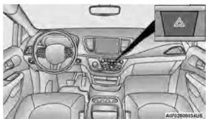
natural_image
Interior view of a car dashboard with steering wheel, dashboard, and control panel (no visible text or symbols)HazardWarningFlashersButton
SOSANDASSISTMIRROR—IFEQUIPPED
iff equipped, the rearview mirror contains an ASSIST button.
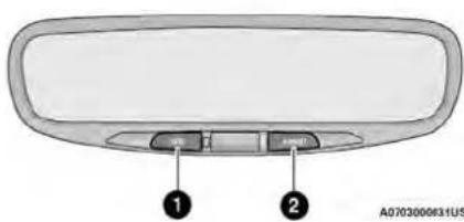
SOSAndASSISTMirror
Push the button to turn on the Hazard Warning Flash-
ers. When the button is activated, all directional1 turn SOS Button
signals will flash on and off to warn oncoming 2 traffic ASIST Button
an emergency. Push the button a second time off the Hazard Warning Flashers.
This is an emergency warning system and it should be used when the vehicle is in motion. Use it your vehicle is disabled or signaling a safety warning for other motorists.
When you must leave the vehicle to seek assist the Hazard Warning Flashers will continue to operate even though the ignition is placed in the OFF
NOTE:
With extended use, the Hazard Warning Flashers wear down your battery.
| would not | WARNING! |
NOTE:
- Your vehicle may be transmitting data as authorized and by the subscriber page 231.
- The SOS and ASSIST buttons will only function if y are connected to an operable LTE (voice/data) or 4 (data) network, which comes as a built-in function. Other Uconnect services will only be operable if you SiriusXM Guardian™ service is active and you are connected to an operable LTE (voice/data) or 4G (data) network.
SOSCall
- Push the SOS Call button on the Rearview Mirror. NOTE:
In case the SOS Call button is pushed in error, the will be a 10 second delay before the SOS Call sys. Initiates a call to an SOS operator. To cancel the S Call connection, push the SOS Call button of Rearview Mirror or press the cancellation but the Device Screen. Termination of the SOS turn off the green LED light on the Rearview Mirror.
- The LED light located between the SOS and Assist buttons on the Rearview Mirror will turn green once the connection to an SOS operator has been made. The Once a connection between the vehicle and an SO operator is made, the SOS Call system may transmature following important vehicle information to an Features operator:
ilure to de injury Indication that the occupant placed an SOS Call The vehicle brand
O The last known GPS coordinates of the vehicle
- You should be able to speak with the SOS through the vehicle audio system to determine additional assistance is needed.
WARNING!
ALWAYS obey traffic laws and pay attention to road. ALWAYS drive safely with your hands on steering wheel. You have full responsibility and assume all risks related to the use of the f and applications in this vehicle. Only use the and applications when it is safe to do so. F so may result in an accident involving serious or death.
NOTE:
-
Your vehicle may be transmitting data as rized by the subscriber.
Once a connection is made between the vehicle's SOS Call system and the SOS operator SOS operator may be able to open a voice connection with the vehicle to determine if additional assistance is needed. Once the SOS operator opens a voice connection with the vehicle SOS Call system, the operator should be able to speak with you or other vehicle occupants at hear sounds occurring in the vehicle. The vehicle's SOS Call system will attempt to remain nexted with the SOS operator until the SOS operator terminates the connection. -
The SOS operator may attempt to contact aate emergency responders and provide them w important vehicle information and GPS coordinat
| operatorif | WARNING! |
| ● If anyone in the vehicle could be in da fire or smoke is visible, dangerous road or location), do not wait for voice contact Emergency Services Agent. All occupants sit the exit the vehicle immediately and move to the location. | |
| ● Never place anything on or near the veh tures, feature, and ensure to do which can prevent your vehicle from place emergency call. An operable network and nal reception is required for the SOS Ca function properly. | |
| ● The SOS Call system is embedded into the role's electrical system. Do not add afterm electrical equipment to the vehicle's electric hi-tem. This may prevent your vehicle from r, signal to initiate an emergency call. To a deference that can cause the SOS Call sys i- never add aftermarket equipment (e.g., two operable radio, CB radio, data recorder, etc.) vehicle's electrical system or modify the a pole by your vehicle. IF YOUR VEHICLE LOSES and POWER FOR ANY REASON (INCLUDING DUR ehi-AFTER AN ACCIDENT), THE UCONNECT FEAT in ARPS AND SERVICES, AMONG OTHERS, WIL OPERATE. | |
| ● Modifications to any part of the SOS Ca propri-th need it. You could be injured if the air is not there to help protect you. | |
SOSCallSystemLimitations
Vehicles sold in Mexico DONOThave SOS Call system capabilities.
conditions or other emergency line operators in Mexico may not from answer or respond to SOS system calls. Should if the SOS Call system detects a malfunction, any of a following may occur at the time the malfunction is detected, and at the beginning of each ignition cycle: vehicle's oper- the Rearview Mirror light located between the SOS pre and Assist buttons will continuously illuminate red. In an sense "Vehicle device requires service. Please con- GPS static an authorized dealer."
- An In-Vehicle Audio message will state "Vehicle device requires service. Please contact an authorized dealer."
sys odins
inter.
ignoring the Rearview Mirror light could mean you will not have SOS Call services. If the Rearview Mirror light is illuminated, have an authorized dealer service the SOS Call system immediately.
TERM: Occupant Restraint Control module turns on ORe Air Bag Warning Light on the instrument panel, if a malfunction in any part of the system is OTdetected. If the Air Bag Warning Light is illuminated, have an authorized dealer service the Occu-plant Restraint Control system immediately.
when you
bag system
Even if the SOS Call system is fully functional, beyond FCA US LLC's control may prevent or stop SOS Call system operation. These include, but are limited to, the following factors:
• The ignition is in the OFF position
- The vehicle's electrical systems are not intact
- The SOS Call system software and/or hardware damaged during a crash
- The vehicle battery loses power or becomes nected during a vehicle crash
- LTE (voice/data) or 4G (data) network and/or Positioning Satellite signals are unavailable or obstructed
• Equipment malfunction at the SOS operator
- Operator error by the SOS operator
- LTE (voice/data) or 4G (data) network conges
- Weather
• Buildings, structures, geographic terrain, or tur
•tablever place anything on or near the vehicle's LTE
top (vthice/data) or 4G (data) and GPS antennas.
could prevent LTE (voice/data) or 4G (data)
signal reception, which can prevent your vehicle
from placing an emergency call. An operable
(voice/data) or 4G (data) network connection ar
GPS signal is required for the SOS Call syste
| LTE You | CAUTION! |
| GPS | |
| To avoid damage to the mirror during clear spray any cleaning solution directly onto the Apply the solution onto a clean cloth and mirror clean. | |
GPS to avoid damage to the mirror during cleaning, never spray any cleaning solution directly onto the mirror. Apply the solution onto a clean cloth and wipe the mirror clean.
NOTE: DISCOFF
Changes or modifications not expressly approved
party responsible for compliance could void the
authority to operate the equipment.
AutomaticSOS—IfEquipped
Automatic SOS is a hands-free safety service t
immediately connect you with help in the event that
your vehicle's air bags deploy. Please refer to your pro-
vided radio supplement for complete information.
that
your pro-
[Non-Text]
ASSISTCall
The ASSIST button is used to automatically connect you
to any one of the following support centers:
-
Roadside Assistance - If you get a flat tire,
a tow, just push the ASSIST button and you
the connected to a representative for assistance.
the side Assistance will know what vehicle is beir
driven and its location. Additional fees may a
roadside assistance.
SiriwsXM _10 Guardian™ Customer Care - In-vehicle
inisupport for SiriusXM Guardian™ -
Vehicle Customer Care - Total support for all
vehicle - Uconnect Customer Care - Total support for
Phone and NAV issues. - Vehicle Customer Care - Total support for all
vehicle - Uconnect Customer Care - Total support for
Phone and NAV issues.
JACKINGANDTIRECHANGING— by the IFEQUIPPED
UsethisQRcodetoaccessyourdigital
experience.
that
[Non-Text]
WARNING!
ALWAYS obey traffic laws and pay attention to road. ALWAYS drive safely with your hands of steering wheel. You have full responsibility and assume all risks related to the use of the and applications in this vehicle. Only use the and applications when it is safe to do so, so may result in an accident involving serious or death.
or need WARNING!
will be
Road Do not attempt to change a tire on the
ing vehicle close to moving traffic. Pull far enough off
apply the road to avoid the danger of being hit when
operating the jack or changing the wheel.
- Being under a jacked-up vehicle is dangerous. The vehicle could slip off the jack and fall on you. You could be crushed. Never put any part of your body under a vehicle that is on a jack. If you need to under a raised vehicle, take it to a service center Radio where it can be raised on a lift.
(Continued)
NOTE:
- Your vehicle may be transmitting data as authorized by the subscriber.
WARNING!
- The jack is designed to be used as a changing tires only. The jack should not lift the vehicle for service purposes. The should be jacked on a firm level surface ice or slippery areas.
tool for be used to vehicle only. Avoid
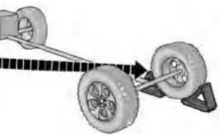
natural_image
Diagram of a vehicle chassis with wheels and a connecting rod, showing motion direction (no text or symbols)A0707001133US
PREPARATIONS FOR JACKING
- Park the vehicle on a firm, level surface. Avoid ice or slippery areas.
WARNING!
Do not attempt to change a tire on the vehicle close to moving traffic. Pull far end road to avoid being hit when operating the changing the wheel.
NOTE:
Passengers should not remain in the vehicle when side vehicle is being lifted or raised.
ugh off the jack JACK AND SPARE TIRE LOCATION
The jacking tools, spare tire and portable air com sor (if equipped) or tire service kit (if equipped) stowed behind an access panel on the left hand the vehicle.
EQUIPMENT REMOVAL
- Remove the access panel to the jacking equipment.
- Unlatch the Portable Air Compressor or Tire Service Kit if equipped. Unscrew the wing nut that is hold the Inflatable Spare Tire and gently remove it from the storage area. Remove wrench from foam tray.
NOTE:
Depending on the trim level of the vehicle, the options for spare tire equipment may vary.
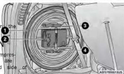
JackingEquipment
1 - Inflatable Spare Tire
2 - Tire Service Kit
3 - Wrench
4 - Fuel Filler Funnel
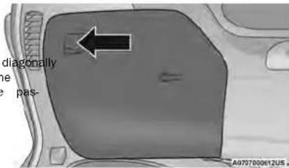
JackingEquipmentLocation
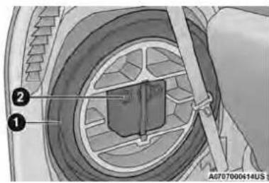
JackIngEquipment
1 - Inflatable Spare Tire 2 - Portable Air Compressor
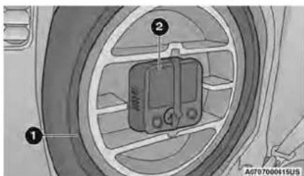
JackingEquipment
1 - Inflatable Spare Tire 2 - Portable Air Compressor
Detailed information about the inflatable spare use, and operation can be foundagen 217.
- Remove Jack by turning the jack screw counterclockwise to collapse from storage area that is located behind the tire. Do
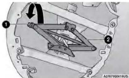
JackLocation
1 - Jack Screw 2 - Jack
JACKING INSTRUCTIONS
WARNING!
Carefully follow these tire changing warnings prevent personal injury or damage to your
- Always park on a firm, level surface as edge of the roadway as possible before vehicle.
• Turn on the Hazard Warning Flashers. - Apply the parking brake firmly and set the mission in PARK.
- Block the wheel diagonally opposite the wheel to be raised.
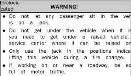
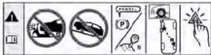
00000714
JackWarningLabel
| from theCAUTION! |
| Do not attempt to raise the vehicle by jacking on l tions other than those indicated in the jacking Instructions for this vehicle. |
(Continued)
[Non-Text]
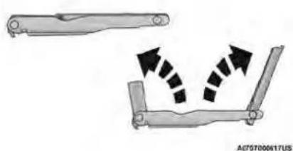
natural_image
Diagram of a mechanical lever mechanism with directional arrows indicating motion (no text or symbols)ExtendingTheWrenchJackLocations
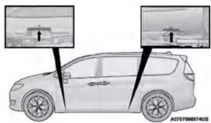
natural_image
Side view of a car with two zoomed-in insets showing terrain or water surface changes (no text or symbols)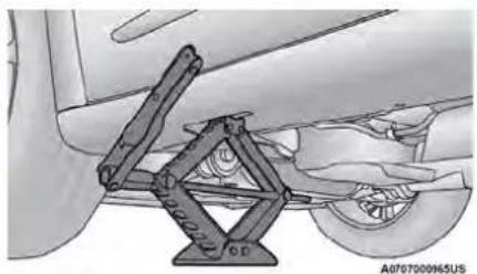
natural_image
Mechanical assembly diagram showing a lever mechanism mounted on a vehicle (no text or symbols visible)FrontJackLocation
- Loosen (but do not remove) the wheel lug turning them to the left, one turn while the still on the ground.
- There are two jack engagement locations on side of the vehicle body. These locations are sill flange of the vehicle body.
NOTE:
Placement for the front and rear jacking are critical. See the following images for ing locations.
| ung nuts by the wheel is WARNING! |
| Being under a jacked-up vehicle is dangerous vehicle could slip off the jack and fall on could be crushed. Never get any part of y under a vehicle that is on a jack. If you under a raised vehicle, take it to a service where it can be raised on a lift. |
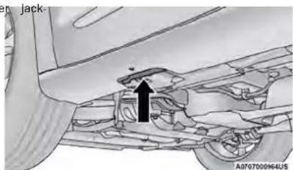
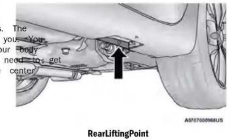
FrontLiftingPoint
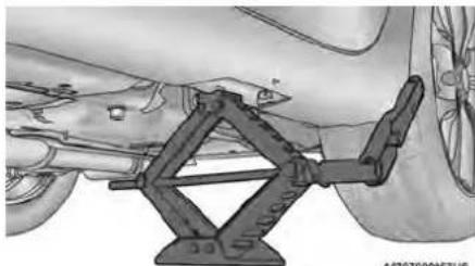
natural_image
Technical illustration of an aircraft wing assembly with no visible text or symbolsRearJackingLocation
CAUTION!
Do not attempt to raise the vehicle by jacking tions other than those indicated.
- Remove the wheel lug nuts, for vehicles covers, remove the cover from the wheel. Do not pry the wheel cover off. Then put off the hub.
- Install the inflatable spare on the vehicle, the rear cargo area of the vehicle.
WARNING!
To avoid the risk of forcing the vehicle of not tighten the wheel nuts fully until the v been lowered. Failure to follow this warning result in serious injury.
with wNOTE: by hard not install the wheel cover on the inflatable all the wheel tire.
- Leave the vehicle on the jack and start inflating a located flatable spare after the tire has been mounted to the vehicle. Secure the wheel to the hub by tightening the nuts with the wrench. After inflation, once the vehicle is lowered you will have a second opportunity to "torque" the lug page 223.
the jack, do vehicle has (4.2 Bar) using the Portable Air Compressor may page 171 or Tire Service Kit if equipped page 172. - Lower the vehicle once the inflatable Spare has reached its pressure and the compressor-hose has been removed from the tire valve.
- Finish tightening the lug nuts. Push down on the wrench while at the end of the handle for increased leverage. Tighten the lug nuts in a star pattern until each nut has been tightened twice page 223. If in doubt about the correctness, have them checked with a torque v an authorized dealer or at a service station.
- Lower the jack to its fully-closed position.
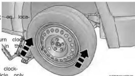
MountingInflatableSpareTire
WARNING!
Raising the vehicle higher than necessary can the vehicle less stable. It could slip off the hurt someone near it. Raise the vehicle only to remove the tire.
CAUTION!
Be sure to mount the inflatable spare tire valve stem facing outward. The vehicle could aged if the inflatable spare tire is mounted in an incorrectly. Jack and enough
WARNING!
A loose tire or jack thrown forward in a collision or hard stop could endanger the occupants of the vehicle. Always stow the jack parts and the spare tir in the places provided. Have the deflated (flat) tire repaired or replaced immediately.
- Place the deflated (flat) tire and foam tray assembly in the rear cargo area. Donotstowth deflated tire in the inflatable spare tire location.
Have the full-sized tire repaired or replaced, soon as possible.
ROAD TIRE INSTALLATION
VehiclesEquippedWithWheelCovers
-
Mount the road tire on the axle.
-
Stow the jack back in the stowage compartment to ease the installation process for steel and place the access panel back. The stud of with the wheel covers, install two lug nuts on storage area must be threaded through the lowering studs which are on each side of the part of the jack. Then turn the Jack Screw clust all the lug nuts with the cone shaped wise to secure it in place. nut toward the wheel. Lightly tighten the l
-
Install the remaining lug nuts with the cone shape end of the nut toward the wheel. Lightly tighten all the lug nuts until the wheel sits flush onto the h and there is no play. The nuts will have to be tightened once the vehicle is lowered. Tightening an improperly seated wheel under vehicle load can damage the threads, cause vibration, and under-mine safety. valve stem.
NOTE:
Stow the foam tray and components in the cargo area.
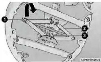
StoringTheJack
1 - Jack Screw
2 - Jack
3 - Stud
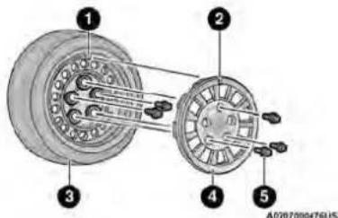
TireAndWheelCoverOrCenterCap
1 - Valve Stem
2 - Valve Notch
3 - Road Tire
4 - Wheel Cover
5 - Wheel Lug Nut
- Align the valve notch in the wheel cover valve stem on the wheel. Install the cover snapping the cover over the two lug nuts. a hammer or excessive force to install the
| d of thenuts. | WARNING! |
| To avoid the risk of forcing the vehicle of not tighten the wheel nuts fully until the t been lowered. Failure to follow this warning result in serious injury. | |
- Lower the vehicle to the ground by turning the ja handle counterclockwise.
- Finish tightening the lug nuts. Push down on the wrench while at the end of the handle for increase leverage. Tighten the lug nuts in a star pattern un each nut has been tightened twice. Details for proper wheel lug nut to page 223. If in doubt about the correct tightness, have them checked with a torque wrench by an authorized dealer or at a service station.
- After 25 miles (40 km) check the lug nut torque a torque wrench to ensure that all lug nuts are properly sealed against the wheel.
with the by hand, Do not use cover.
PORTABLE AIR COMPRESSOR IF EQUIPPED
— PortableAirCompressorUsageWithInflatableSpare Tire
Your vehicle may be equipped with a Portable pressor. Use the Portable Air Compressor located side compartment of the cargo area to inflate able tire to 60 psi (4.2 Bar).
- Remove the Portable Air Compressor from the Air age location.
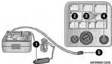
PortableAirCompressor
1-PowerPlug
2 - Deflation Button
3 - Pressure Gauge
4 - Power Button
5 - Air Hose
- Raise the vehicle as described in the Inhat Jacking Instructions within this sect

- Install the Inflatable Spare tire as described in the Jack Instructions in this manual. Make sure that the stem is located near the ground, then screw the air hose of the sor to the valve stem.

- Uncoil the power plug and conne vehicles 12 Volt power Outlet.

- Always start the engine before tu ON the Portable Air Compressor.

- Switch the power button ON.

- Inflate the tire to 60 psi (4.2) recommended as per the label on the wheel for if the vehicle equipped with the spare tire pressure indicated on the and Loading Information label located on the side door opening.
NOTE:
If the tire is overinflated, use the deflation button reduce the tire air pressure.
- After the tire reaches the recom pressure, lower the vehicle with th as described in the Jack Instructio tion in this manual.

- Remove the speed limit label stick the Portable Air Compressor and p on the center of the steering wh

- Return the Portable Air Compressor to the foam Compres and secure it with the strap. Store the foam tray in the cargo area.
WARNING!
- Do not lift or carry the Portable Air Compressor by the hose.
- Always stow the Portable Air Compressor only in the provided place.
- The metal end fitting from Power Plug ma after use, so it should be handled carefully.
- Keep the Portable Air Compressor away from open flames or heat source.
RETURN INFLATABLE SPARE TIRE TireServiceKitStorage
To return Inflatable Spare Tire to its storage location. Depending on the vehicle trim level, the Tire Service storage may vary.
- Return the Jack.
- Deflate the spare tire. Use the Tire Service Air for Portable Air Compressor page 171 and push the deflation button to do this step. See the Portable Air Compressor in this section for additional information. The inflatable spare tire will return to its original shape.
- Install the inflatable spare tire back into its original stowage location and position facing outward.
- Install the foam tray with wrench and funnel installed.
- Install and tighten the wing nut by hand.
- Install the Tire Service Kit or Portable Air Compressor (if equipped) and tighten the strap.
- Install access panel door.
TIRESERVICEKIT—IFEQUIPPED
UsethisQRcodetoaccessyourdigital experience.
Your vehicle may be equipped v
Tire Service Kit. Small punctures
1/4 inch (6 mm) in the tire t
sealed with Tire Service Kit. For
objects (e.g., screws or nails) should not
be removed from the tire. Tire Service Kit can be used
in outside temperatures down to approximately -4°F
(-20°C). This kit will provide a temporary tire seal,
allowing you to drive your vehicle up to 100 miles
(160 km) with a maximum speed of 50 mph (80 km/h).
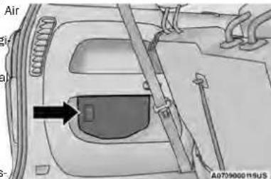
TireServiceKitLocation
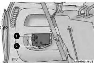
TireServiceKit
1 - Tire Service Kit
2 - Fuel Funnel
Depending on the vehicle trim level, the Tire Service storage may vary.
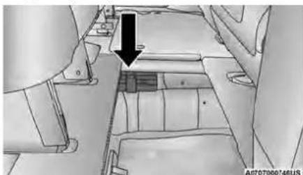
natural_image
Interior view of a vehicle cabin with no visible text or symbolsTireServiceKitLocation—IfEquipped
The Tire Service Kit is secured with a strap and is stored under the load floor within the second row.
TireServiceKitAndComponentsAndOperation
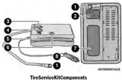
1 - Sealant/Air Hose
2 - Hose Accessories
3 - Mode Select Knob
4 - Pressure Gauge
5 - Deflation Button
6 - Power Switch
7 - Sealant Bottle
8-PowerPlug
UsingTheModeSelectKnobAndHoses
Your Tire Service Kit is equipped with the bols to indicate the air or sealant mode.
- SelectingAirMode
Push in the Mode Select Knob a to this position for air pump open only.

- SelectingSealantMode
Push in the Mode Select Knob a to this position to inject the Tire Kit Sealant and to inflate the tire

• UsingThePowerButton
Push and release the Power Button to turn On the Tire Service Kit. release the Power Button again to Off the Tire Service Kit.

• UsingTheDeflationButton
Push the Deflation Button to reduce air pressure in the tire if it be overinflated.

TireServiceKitUsagePrecautions
- Replace the Tire Service Kit Sealant Bottle print the expiration date (printed at the lower right corner on the bottle label) to ensure optimum tion of the system. See the Sealant Bottle R ment in this section for further information.
- The Sealant Bottle is a one tire application needs to be replaced after each use. Always these components immediately at your original equipment vehicle dealer.
- When the Tire Service Kit sealant is in a lie clean water, and a damp cloth will remove trial from the vehicle or tire and wheel comp Once the sealant dries, it can easily be peel and properly discarded.
-
For optimum performance, make sure the valve stem on the wheel is free of debris before ing the Tire Service Kit.
-
The Tire Service Kit Sealant is only intended to se punctures less than 1/4 inch (6 mm) diameter in the tread/contact surface of your vehicle's tires.
- The Tire Service Kit Sealant is not intended to sea punctures on the tires' side walls.
- You can use the Tire Service Kit air pump to infl bicycle tires. The kit also comes with two needles, located in the Accessory Storage Compartment (on the bottom of the air pump) for inflating sport ball rafts, or similar inflatable items. However, use only the Air Pump and make sure the Mode Select Kn is in the Air Mode when inflating such items to a injecting sealant into them.
- Do not lift or carry the Tire Service Kit by the h
WARNING!
DO not attempt to seal a tire on the side of the hand vehicle closest to traffic. Pull far enough off the open-to- avoid the danger of being hit when using eplane Tire Service Kit.
- Do not use Tire Service Kit or drive the use and the following circumstances: 7
replace If the puncture in the tire tread is approximately 1/4 inch (6 mm) or larger.
If the tire has any sidewall damage. quid form, the tire has any damage from driving with the extremely low tire pressure. ponents. If the tire has any damage from driving on a red offire.
○ If the wheel has any damage. ○ If you are unsure of the condition of the tire connect the wheel. - Keep Tire Service Kit away from open flames or heat source.
(Continued)
WARNING!
- A loose Tire Service Kit thrown forward in sion or hard stop could endanger the othe vehicle. Always stow the Tire Service place provided. Failure to follow these wa can result in injuries that are serious or you, your passengers, and others around
Take care not to allow the contents of Kit to come in contact with hair, eyes, Tire Service Kit sealant is harmful if inhaled, or absorbed through the skin. It is skin, eye, and respiratory irritation. Flush ately with plenty of water if there is any with eyes or skin. Change clothing as so sible, if there is any contact with clothing -
Tire Service Kit Sealant solution contains case of an allergic reaction or rash, conscious immediately. Keep Tire Service Kit reach of children. If swallowed, rinse moudiately with plenty of water and drink ple water. Do not induce vomiting! Consult a immediately.
-
Place the transmission in PARK (P) and cyclNOTE ignition in the OFF position. Sealant
n a 4colApply the parking brake.
cupart SettingUpToUseTireServiceKit: Kit in the mings ^1 . Uncoll the Sealant Hose and then remove fatal to from the fitting at the end of the hose.
you. 2. Place the Tire Service Kit flat Tire Segment next to the deflated tire. or clothing.

aled, swal-
3. Remove the cap from the valve stem and immediately the fitting at the end of the Sealant Hose contact valve stem.
g. 4. Uncoil the Power Plug and insert latex. In plug into the vehicle's 12 Volt point a outlet.
out of
with imme
enty of
physician not remove foreign objects (e.g., screws or
from the tire.

InjectingTireServiceKitSealantIntoTheDeflatedTire:
SealingATireWithTireServiceKit
WheneverYouStopToUseTireServiceKit:
-
Pull over to a safe location and turn on Hazard Warning Flashers.
-
Verify that the valve stem (on the wheel with the deflated tire) is in a position that is near to the ground. This will allow the Tire Service Kit Hose to reach the valve stem and keep the Tire Service Kit flat on the ground. This will provide the best posi-
tioning of the kit when injecting the sealant into Attie pushing the Power Button, deflated tire and running the air pump. Move that (white fluid) will flow from the vehicle as necessary to place the valve stem in Bottle through the Sealant Hose at position before proceeding.


Sealant may leak out through the puncture in the tire If these sealant (whitefluid) does not flow within 0- 10 secondsthrough the Sealant Hose:
the Eash the Power Button to turn the Tire Service K off. Disconnect the Sealant Hose from the valve stem. Make sure the valve stem is free of debris. Reconnect the Sealant Hose to the valve stem. Check that the Mode Select Knob is in the Sealar Mode position and not Air Mode. Push the Power Button to turn the Tire Service Kit on.
then screw Connect the Power Plug to a different 12 Volt po outlet in your vehicle or another vehicle, if available Make sure the vehicle is running before turning the Tire Service Kit on.
- The Sealant Bottle may be empty due to previous use. Call for assistance.
If these sealant(whitefluid) does flow through the Sealant Hose:
-
Continue to operate the pump unit is no longer flowing through (typically takes 30 - 70 seconds). sealant flows through the Sealant the Pressure Gauge can read as high as 70 psi (4.8 Bar). The Pressure Gauge will decrease quickly from approximately 70 psi (4.8 Bar) to the actual tire pressure when the Sealant Bottle is empty.
-
The pump will start to inject air tire immediately after the Sealant Route empty. Continue to operate the pump inflate the tire to the cold tire in pressure found on the tire and loading information label located in the driver-side door opening. Check the tire pressure by looking at the Pressure Gauge.


If the tiredoes not in flat to at least 26 psi (1.8 Bar) pressure within 15 minutes:
• The tire is too badly damaged. Do not attend drive the vehicle further. Call for assistance.
If the tireinflatestotherecommended pressure or is at least 26 psi (1.8 Bar) pressure within 15 minutes:
NOTE:
If the tire becomes overinflated, push the Deflation to reduce the tire pressure to the recommend inflation pressure before continuing.
- Push the Power Button to turn Service Kit off.

- Remove the speed limit label from Tire Service Kit and place sticker steering wheel.

- Immediately disconnect the Sealant Hose from valve stem, reinstall the cap on the fitting of the hose, and place the Tire Service Kit vehicle storage location.
DriveVehicle:

Immediately after Injecting sealant and inflating the tire, drive the vehicle 5 (8 km) or 10 minutes to ensure dis of the Tire Service Kit Sealant within
Do not exceed 50 mph (80 km/h).
WARNING!
The to Tire Service Kit is not a permanent fla Have the tire Inspected and repaired or replaced using the Tire Service Kit. Do not exceed 5 (80 km/h) until the tire is repaired or repaired to follow this warning can result in injury are serious or fatal to you, your passengers, cars. About you. Have the tire checked as possible at an authorized dealer.
- Remove the cap from the valve stem, and then screw the fitting at the end of the Sealant Hose the valve stem.
placed, a coil the Power Plug and insert 50 mplug into the vehicle's 12 Volt placed.

- and 0th- soon as Uncoll the Hose and screw the the end of the hose onto the

AfterDriving:
- Pull over to a safe location and turn on the Hazard Warning Flashers.
- Verify that the valve stem (on the wheel with the
deflated tire) is in a position that is near to the
ground. This will allow the Tire Service Kit Hose Ct
reach the valve stem and keep the Tire Service ^sup
flat on the ground. This will provide the best lift pipe
tioning of the kit when injecting the sealant into
deflated tire and running the air pump. Move the v
vehicle and as necessary to place the valve stem in t
position before proceeding.
retropressure:130 psi(1.5 GB) or higher.
- Place the transmission in PARK (P) and cycle ^1 tl ignition in the OFF position.
- Apply the parking brake.
If tire has improper inflation, see the following the
dution steps. he tire.
e Push the Power Button to turn Service Kit and inflate the tire tire inflation pressure found on and loading information label loca the driver side door opening


-
Uncoll the Sealant Hose, and then remove the from the fitting at the end of the hose.
-
Place the Tire Service Kit flat or ground next to the deflated tire.
NOTE:
If the tire becomes overinflated, push the Deflation Button to reduce the tire pressure to the recommended inflation pressure before continuing.

- Disconnect the Tire Service Kit from the valve8. sRemove the bottle cover.
reinstall the cap on the valve stem and unplug from 12 Volt outlet. - Place the Tire Service Kit in its proper storage area in the vehicle.
- Have the tire inspected and repaired or replaced at the earliest opportunity at an authorized dealer or tire service center.
- Remove the Speed Limit sticker from the steering wheel after the tire has been repaired.
- Replace the Sealant Bottle at an authorized dealer as soon as possible.
NOTE:
When having the tire serviced, advise the authorized dealer or service center that the tire has been sealed using the Tire Service Kit.
SealantBottleReplacement:
- Unwrap the power cord.
- Unwrap the hose.
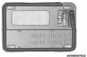
natural_image
Top-down view of a device casing with internal components and mounting holes (no text or symbols visible)HoseLocation
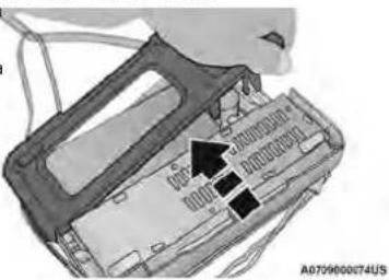
RemoveTheBottleCover
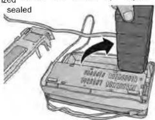
A0701000075U5
- Pull the bottle away from the Compressor.
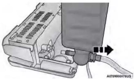
natural_image
Mechanical assembly diagram showing a device with ports and wiring (no text or symbols visible)RemoveTheBottle
NOTE:
- For sealant bottle installation, follow these steps in reverse order.
- The Sealant Bottle is a one tire application use ar needs to be replaced after each use. Always replac these components immediately at your original equipment vehicle dealer.
- Replace the Tire Service Kit Sealant Bottle prior to the expiration date (printed on the bottle label) to ensure optimum operation of the system.
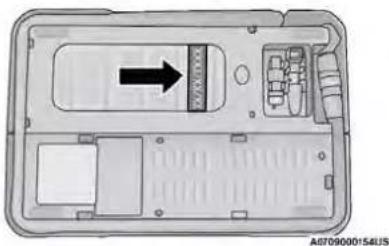
natural_image
Top-down schematic of a device casing with internal compartments and a directional arrow (no text or symbols)SealantBottleExpirationDateLocationBatteryLocation
WARNING!
Do not attempt jump starting if the battery could rupture or explode and cause persona
is
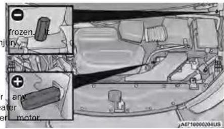
CAUTION!
Do not use a portable battery booster pack other booster source with a system voltage than 12 Volts or damage to the battery, s alternator or electrical system may occur.
1
0
r
a
ny
The image is too blurry to recognize any text content.
The image is too blurry to recognize any text content.
The image is too blurry to recognize any text content.
The image is too blurry to recognize any text content.
2
1
m = 311
m = 311
m = 311
m = 311
The image is too blurry to recognize any text content.
人
-
m = 311
m = 311
m = 311
m = 311
•
The image is too blurry to recognize any text content.
m = 311
m = 311
m = 311
•
1
| CAUTION! |
| Dispose of the bottle and the sealant liquid Have them disposed of in compliance with and local regulations. |
JUMPSTARTING
If your vehicle has a discharged battery it can started using a set of jumper cables and a be another vehicle or by using a portable battery to pack. Jump starting can be dangerous if done early so please follow the procedures in this sec carefully.
NOTE:
When using a portable battery booster pack follow manufacturer's operating instructions and precautions
PREPARATIONS FOR JUMP STARTNOTE:
The battery in your vehicle is located on the properly engine compartment.
onal
The positive battery post may be covered with a protective side of Lift up on the cap to gain access to the tive battery post. Do not jump off fuses. Only jump directly off positive post which has a positive (+) symbo on or around the post.
Take care to avoid the radiator cooling t ever the hood is raised. It can start an ignition switch is ON. You can be injured befarjumplades.
an See the following steps to prepare for jump starting:
Remove any metal jewelry such as rings, boosts and bracelets that could make an important electrical contact. You could be serious injured.
time1. the apply the parking brake, shift the automatic by motion into PARK (P) and place the ignition 7
- Batteries contain sulfuric acid that can bus skin or eyes and generate hydrogen gas flammable and explosive. Keep open flames the sparks away from the battery.
- Turn off the heater, radio, and all electrical watch accessories.
sly 3. Pull upward and remove the protective cap over the positive (+)battery post.
In your if using another vehicle to jump start the battery, which park the vehicle within the jumper cables reach, see or the parking brake and make sure the ignition is 0
WARNING!
Do not allow vehicles to touch each other as could establish a ground connection and personal injury could result.
tD
tDis not connect the jumper cable to the neg post of the discharged battery. The resulting e spark could cause the battery to explode and result in personal injury.
WARNING!
eg
accessories plugged into the vehicle power outlets electrical power from the vehicle's battery, even when not couldise (i.e., cellular devices, etc.). Eventually, if plugged in long enough without engine operation, the vehicle's battery will discharge sufficiently to degrade battery life and/or prevent the engine from starting.
Failure to follow this jump starting procedure result in personal injury or properly damage battery explosion.
- Start the engine in the vehicle that has t battery, let the engine idle a few minutes, start the engine in the vehicle with the dis battery.
due ^6 . to Once the engine is started, follow the discor procedure.
CAUTION!
REFUELINGINEMERGENCY- IFEQUIPPED
CAUTION!
Failure to follow these procedures could result damage to the charging system of the booster or the discharged vehicle.
DisconnectingTheJumperCables
- Disconnect the negative (-)end of the jumper from the remote negative post of the vehicle the discharged battery.
- Disconnect the opposite end of the negative jumper cable from the negative (-)post of the booster battery.
The vehicle is equipped with a refueling funnel for a carless fuel system page 166. If emergency refueling with its necessary, use an approved gas can and insert the refueling funnel into the filler pipe opening. Take care to open both flappers with the funnel to avoid
- Disconnect the positive (+)end of the jumper from the positive (+)post of the booster batte ble to
- Disconnect the opposite end of the positive jumper cable from the positive (+)post of the vehicle with the discharged battery and reinsta umper protective cap. battery. If frequent jump starting is required to start yo you should have the battery and charging syster inspected at an authorized dealer.
WARNING!
Never have any smoking materials lit in or near the vehicle when the fuel door is open or the tank is being filled.
Never add fuel when the engine is running. This is in violation of most state and federal fire regulations and may cause the Malfunction Indicator vehicle Light to turn on.
- A fire may result if fuel is pumped into a portab container that is inside of a vehicle. You could be burned. Always place fuel containers on the ground while filling.
ConnectingTheJumperCables
- Connect the positive (+)end of the jumper the positive (+)post of the vehicle with the charged battery.
cable to dis: Disconnect the opposite end of the positive jumper cable from the positive (+)post of the vehicle with the discharged battery and reinsta (+)jumper protective cap. battery. If frequent jump starting is required to start yo cable should have the battery and charging syster inspected at an authorized dealer.
-
Connect the opposite end of the positive cable to the positive (+)post of the booster
-
Connect the negative (-)end of the jumper the negative (-)post of the booster battery.
-
Connect the opposite end of the negative (-)jumper cable to the remote negative (-)post (exposed metallic/unpainted post of the discharge vehicle) near the windshield cowl.
NOTE:
In certain cold conditions, ice may prevent the from opening. If this occurs, lightly push on the door to break the ice buildup. Then push on center edge of the fuel door to re-release. Do the door.
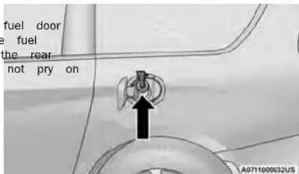
InsertingFunnel
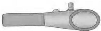
natural_image
Illustration of a mechanical tool or device with a cylindrical body and flanged ends (no text or symbols visible)A8711000613U5
RefuellingFunnel
EmergencyGasCanRefueling
Most gas cans will not open the flapper doors. is provided to allow emergency refueling with a See the following steps for refueling:
- Retrieve funnel from the spare tire storage
-
Insert funnel into the fuel filler pipe openi
-
Ensure funnel is inserted fully to hold flapper open.
-
Pour fuel into funnel opening.
| CAUTION! |
| To avoid fuel spillage and overfilling, do no the fuel tank after filling. |
gas can.
5. Remove funnel from filler pipe, clean off prior putting back in the spare tire storage area.
IFYOURENGINEOVERHEATS
If the vehicle is overheating, it will need to be by an authorized dealer.
Potential signs of vehicle overheating:
• Temperature gauge is at HOT (H)
• Strong smell of coolant
- White smoke coming from engine or exhaust
- Coolant bottle coolant has bubbles present
WARNING!
You or others can be badly burned by ho ant (antifreeze) or steam from your radiator. see or hear steam coming from under the not open the hood until the radiator has cool. Never try to open a cooling system when the radiator or coolant bottle is hot.
: engine c If you hood, do had time pressure ca
If the temperature gauge is moving towards or close the HOT (H) position, you can reduce the potential fo overheating by taking the appropriate action.
- On highways — slow down.
- Door city traffic - while stopped, place the transmission in NEUTRAL (N), but do not increase the engine idle speed while preventing vehicle motion with the brakes.
- Turn off the Air Conditioner (A/C). The A/C system adds heat to the engine cooling system and turning the A/C off can help remove this heat.
- Turn the temperature control to maximum heat the mode control to floor and the blower control. This allows the heater core to act as a 10 to the radiator and aids in removing heat from the engine cooling system.
CAUTION!
D Annived with a hot cooling system could damage your vehicle. If temperature gauge reads "H", pull over and stop the vehicle. Idle the vehicle with the air conditioner turned off until the pointer drops back into the normal range. If the pointer remains on the "H", turn the engine off immediately, and call for service.
MANUALPARKRELEASE
WARNING!
You should be seated in the driver's seat foot firmly placed on the brake pedal to control of the vehicle before activating the Manual Release. If possible, you should apply the brake. Activating the Manual Park Release with your vehicle to roll away if it is not secured connected to a tow vehicle. Activating the Park Release on an unsecured vehicle could serious injury or death for those in or around vehicle.
FollowTheseStepsToActivateTheManualPark Release:
- Apply firm pressure to the brake pedal in the driver's seat.
with 2 your Apply the parking brake, if possible. maintain using a small screwdriver or similar tool, manual Park Manual Park Release access cover, which is parking lower left of the steering column. will allow red or propen The Manual Park Release access cover is Manual to a red tether strap. Pull the tether strap lead as it will go, then release it. The transmiss found that now be in NEUTRAL (N), allowing the vehicle moved.
ToResetTheManualParkRelease:
-
Apply firm pressure to the brake pedal while seat e seatde driver's seat.
-
Pull the tether strap out again, then release it.
-
Allow the tether to retract with the lever back to moving original position.
to the 4. Verify that the transmission is in PARK (P).
- Confirm that the tether has retracted fully and rein connected to stall the access cover. If the access cover cannot out as far, reinstalled, repeat steps 1 through 4.
To move the vehicle in cases where the will not shift out of PARK (P) (such as tery), a Manual Park Release is available.
transmission a depleted bat-
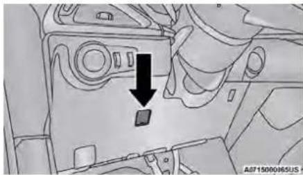
natural_image
Interior view of a vehicle dashboard with a black arrow pointing to a component (no text or symbols visible)ManualParkReleaseAccessCover
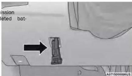
TetherStrap
NOTE:
When the lever is locked in the released the tether will remain outside of the trim the access cover cannot be reinstalled.
If your vehicle becomes stuck in mud, sand or snow, can often be moved using a rocking motion. Turn the steering wheel right and left to clear the area around the front wheels. Then shift back and forth between DRIVE (D) and REVERSE (R) while gently pressing the accelerator.
NOTE:
Shifts between DRIVE and REVERSE can only be achieved at wheel speeds of 5 mph (8 km/h) or less. Whenever the transmission remains in NEUTRAL (N) for more than two seconds, you must press the brake pedal to engage DRIVE or REVERSE.
Use the least amount of accelerator pedal pressure that will maintain the rocking motion without spinning position, the wheels or racing the engine. and
- Release the parking brake only when the vehicle is securely connected to a tow vehicle.
NOTE:
Push the ESC OFF button to place the Electronity Control (ESC) system in "Partial Off" mode, rocking the vehicle page 119. Once the vehicle been freed, push the ESC OFF button again to "ESC On" mode.
WARNING!
Fast spinning tires can be dangerous. Forces go ated by excessive wheel speeds may cause dam or even failure, of the axle and tires. A tire explode and injure someone. Do not spin your cle's wheels faster than 30 mph (48 km/h) or ger than 30 seconds continuously without stopping when you are stuck and do not let anyone no spinning wheel, no matter what the speed.
| c. Stabil- | CAUTION! |
| Before has | at the engine or spinning the wheels may lead to transmission overheating and failure. Allow the restone engine to idle with the transmission in NEUTRAL for at least one minute after every five rocking- motion cycles. This will minimize overheating and reduce the risk of transmission failure during pro- longed efforts to free a stuck vehicle. |
| After mage | When "rocking" a stuck vehicle by shifting between DRIVE and REVERSE, do not spin the wheels faster than 15 mph (24 km/h), or drivetrain damage may velti-result. |
| could vehi | for lon- Reving the engine or spinning the wheels too fast may lead to transmission overheating and failure. It can also damage the tires. Do not spin the wheels above 30 mph (48 km/h) while in gear (no transmission shifting occurring). |
TOWINGADISABLEDVEHICLE
This section describes procedures for towing a disabled vehicle using a commercial towing service.
| TowingConditionWheelOFFTheGround | ALLMODELS | |
| Flat Tow NONE NOTALLOWED | ||
| Wheel Lift Or Dolly Tow | Front ACCEPTABLEMETHOD | |
| Rear NOTALLOWED | ||
| Flatbed ALLBESTMETHOD | ||
Proper towing or lifting equipment is required to prevent damage to your vehicle. Use only tow bars and other equipment designed for this purpose, following equipment manufacturer's instructions. Use of safety chains is mandatory. Attach a tow bar or other towing device to main structural members of the vehicle, not to fascia/bumper or associated brackets. State and local laws regarding vehicles under tow must be observed.
NOTE:
- You must ensure that the Auto Park Brake feature is equipped with Vehicle Recovery disabled before towing this vehicle (if rear wheels can be used to recover a disabled vehicle are on the ground). In avoid inadvertent Election on the underbody of the vehicle.
Park Brake (EPB) engagement. The Auto Park feature is enabled or disabled via the customer pro-
grammable features in the Uconnect Settings. • Ensure that the towing service tow hooks are
- Vehicles with a discharged battery or total electrical safety seated and secured in the attachment p failure when the Electric Park Brake (EPB) is - This recovery tow feature should be used by engaged, will need a wheel dolly or jack to raise the professional only.
rear wheels off the ground when moving the vehicle onto a flatbed. • Use approved receptacle location to free the abled vehicle from its environment
FCA US LLC recommends towing your vehicle with all four wheels OFFthe ground using a flatbed.
If flatbed equipment is not available, this vehicle must be towed with the front wheels OFFthe ground (using towing dolly, or wheel lift equipment with the front wheels raised).
NOTE:
Ensure that the Electric Park Brake is released, and remains released, while being towed.
CAUTION!
Towing this vehicle in violation of the approved requirements can cause severe transmission damage. Damage from improper towing is not covered under the New Vehicle Limited Warranty.
VehicleRecoveryTowPoints
Your vehicle is equipped with Vehicle Recovery
that can be used to recover a disabled vehicle on the underbody of the vehicle.
Note: er pro
- Ensure that the towing service tow hooks are early seated and secured in the attachment p ctrical
- This recovery tow feature should be used by raising the professional only.
vehicle • Use approved receptacle location to free the abled vehicle from its environment.
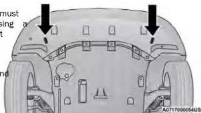
FrontRecoveryPoints
| Points | CAUTION! |
| Recovery feature: | |
| Is to be used by a professional ONLY. | |
| Is used only to provide recovery of the | |
| Is NOT to be used to recover secondary | |
| prop- | |
| NOT to be used for transporting the | |
| the road, i.e. “Flat Towing”. | |
| a | |
| Recovery load should: | |
| Be applied at constant speed. | |
| dis- | |
| Be applied parallel to the center line of | |
| of the vehicle. | |
| Not be an abrupt acceleration. | |
If you must use the accessories (wipers, defrosters, etc.) while being towed, the ignition must be in the ON/RUN mode, not the ACC mode.
NOTE:
The Safehold feature will engage the Electric Park Brake whenever the driver's door is opened (if the ignition is ON, transmission is not in PARK, and brake is released). If you are towing this vehicle with the ignition in the ON/RUN mode, you must manually disable the Electric Park Brake each time the driver's door is opened, by pressing the brake pedal and then releasir the EPB.
If the key fob is unavailable or the vehicle's battery discharged, detailed instructions on shifting the transmission out of PARK in order to move the vehicle page 180.
CAUTION!
- Do not use sling-type equipment when towing. Vehicle damage may occur.
- When securing the vehicle to a flatbed truck, do not attach to front or rear suspension components. Damage to your vehicle may result from improper towing.
- Ensure that the Electric Park Brake is released, and remains released, while being towed.
ENHANCEDACCIDENTRESPONSESYSTEM (EARS)
This vehicle is equipped with an Enhanced Accident Response System.
This feature is a communication network that takes effect in the event of an ➕ project 146.
EVENTDATARECORDER(EDR)
This vehicle is equipped with an event data recorder (EDR). The main purpose of an EDR is to record data that will assist in understanding how a vehicle's systems performed under certain crash or near crash-like situations, such as an air bag deployment or hitting a road obstacle page 147.
SERVICINGANDMAINTENANCE
SCHEDULEDSERVICING
An authorized dealer will reset the oil change iOnceAMonthOrBeforeALongTrip:
message after completing the scheduled oil change. If check engine oil level.
Your vehicle is equipped with an automatic oil change, a scheduled oil change is performed indicator system. The oil change indicator system will be an authorized dealer page 60.
remind you that it is time to take your vehicle in for scheduled maintenance.
Based on engine operation conditions, the oil change under no circumstances should oil change intervals wear, even if it occurs before the oil indicator syst. exceed 10,000 miles (16,000 km), 12 months or turns on.
Indicator message will illuminate. This means that service is required for your vehicle. Operating conditions such as frequent short-trips, trailer tow extremely hot 350 hours of engine run time, whichever comes • for check the fluid levels of the coolant reservoir and the 350 hours of engine run or idle time is generally master cylinder, fill as needed.
such as frequent short-tips, trailer tow, extremely only a concern for fleet customers. or cold ambient temperatures will influence when the
"Oil Change Required" message is displayed. Have your
vehicle serviced as soon as possible, within the next
500 miles (805 km).
- Check tire pressure and look for unusual wear or damage. Rotate tires at the first sign of irregular
als wear, even if it occurs before the oil indicator syst or turns on.
- Check the fluid levels of the coolant reservoir and generally master cylinder, fill as needed.
- Check function of all interior and exterior lights.
MAINTENANCE PLAN
Refer to the Maintenance Plan for required maintenance.
AtEveryOilChangeIntervalAsIndicatedByOilChangeIndicatorSystem
| · Change oil and filter. |
| · Rotate the tires at the first sign of irregular wear, even if it occurs before the oil indicator system turns on. |
| · Inspect battery and clean and tighten terminals as required. |
| · Inspect the CV/Universal joints. |
| · Inspect brake pads, shoes, rotors, drums, hoses and parking brake. |
| · Inspect engine cooling system protection and hoses. |
| · Inspect exhaust system. |
| · Inspect engine air cleaner filter if using in dusty or off-road conditions. If required, replace engine air cleaner filter. |
| MileageOrTimePassed(WhicheverComesFirst) | 20,000 | 30,000 | 40,000 | 50,000 | 60,000 | 70,000 | 80,000 | 90,000 | 100,000 | 110,000 | 120,000 | 130,000 | 140,000 | 150,000 |
| O r | Y | e | a | r | s | : | 2 | 3 | 4 | 5 | 6 | 7 | 8 | 9 |
| OrKilometers: | 32,000 | 48,000 | 64,000 | 80,000 | 96,000 | 112,000 | 128,000 | 144,000 | 160,000 | 176,000 | 192,000 | 208,000 | 224,000 | 240,000 |
| AdditionalInspections | ||||||||||||||
| Inspect the CV/Universal joints. X XXXXXXXXXXX | ||||||||||||||
| Inspect front suspension, boot seals, tie rod ends, and replace | f necessary. X | XXXXXX | ||||||||||||
| Inspect the brake linings, parking brake function. X XXXXXX | ||||||||||||||
| Inspect front accessory drive tensioner, idler pulley, and replace if necessary. | ||||||||||||||
| AdditionalMaintenance | ||||||||||||||
| Replace engine air cleaner filter. | X | X | X | X | X | |||||||||
| Replace cabin air filter. | To be replaced every 12,000 miles (19,000 km). | |||||||||||||
| Replace spark plugs. | X | |||||||||||||
| Replace the front accessory drive belt. | ||||||||||||||
| Flush and replace the engine coolant at 10 years or 150,000 (240,000 km) whichever comes first. | miles | X | X | |||||||||||
| Replace PCV valve. | X | |||||||||||||
** The spark plug change interval is mileage based only; yearly intervals do not apply.
WARNING!
- You can be badly injured working on or around a motor vehicle. Do only service work for which you have the knowledge and the right equipment. If you have any doubt about your ability to perform a service job, take your vehicle to a competent mechanic.
● Failure to properly inspect and maintain your vehicle could result in a component malfunction and affect vehicle handling and performance. This could cause an accident.
ENGINECOMPARTMENT
3.6L ENGINE
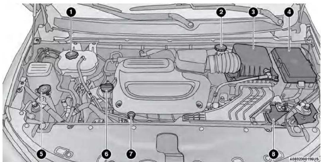
1 - Engine Coolant Pressure Cap 5 - Windshield Washer Reservoir Cap
2 - Brake Fluid Reservoir Cap 6 - Engine Oil Fill
3 - Engine Air Cleaner Filter 7 - Engine Oil Dipstick
4 - Power Distribution Center (Fuses) 8 - Battery
CHECKING OIL LEVEL
To ensure proper engine lubrication, the engine be maintained at the correct level. Check the regular intervals, such as every fuel stop. The to check the engine oil level is about five m a fully warmed up engine is shut off.
Checking the oil while the vehicle is on level improve the accuracy of the oil level readings.
There are four possible dipstick types:
- Crosshatched zone.
• Crosshatched zone marked SAFE. - Crosshatched zone marked with MIN at the of the range and MAX at the high end of
- Crosshatched zone marked with dimples at the containers.
econthamers.
and the MAX ends of the range.
ADDING WASHER FLUID
The fluid reservoir is located in the front of the abirpardment. Be sure to check the fluid level in reservtime at regular intervals. Fill the reservoir with windshifter washer solvent (not radiator antifreeze) operate the system for a few seconds to flush residual washer fluid.
When refilling the washer fluid reservoir, take son washer fluid, apply it to a cloth or towel, and the wiper blades; this will help blade performance
To prevent freeze-up of your windshield washer sy in cold weather, select a solution or mixture that by the exceeds the temperature range of your climate rating range information can be found on most washer
WARNING!
• battery fluid is a corrosive acid solution and can burn or even blind you. Do not allow battery fluid contact your eyes, skin, or clothing. Do not lean over a battery when attaching clamps. If acid splashes in eyes or on skin, flush the area immediately with large amounts of wage 177.
Battery gas is flammable and explosive. Keep
wipe clean.
flame or sparks away from the battery. Do not us
a booster battery or any other booster source with
an output greater than 12 Volts. Do not allow cat
t meets
clamps to touch each other.
- Battery posts, terminals, and related accessories
fluid
contain lead and lead compounds. Wash hands
after handling.
NOTE:
Always maintain the oil level within the crosshato markings on the dipstick.
Adding 1 qt (1 L) of oil when the reading is end of the dipstick range will raise the oil level high end of the range marking.
WARNING!
Commercially available windshield washer solvents are flammable. They could ignite and burn you, must the less exercised when filling or working around washer the solution.
CAUTION!
Care
- It is essential when replacing the cables on the battery that the positive cable is attached to the positive post and the negative cable is attached to the negative post. Battery posts are marked positive (+) and negative (-) and are identified on the battery case. Cable clamps should be tight at terminal posts and free of corrosion.
8
If a "fast charger" is used while the battery is in the vehicle, disconnect both vehicle battery cables before connecting the charger to the battery. Do not use a "fast charger" to provide starting voltage
8
| CAUTION! |
| Overfilling or underfilling the crankcase will aeration or loss of oil pressure. This could your engine. |
MAINTENANCE-FREE BATTERY
Your vehicle is equipped with a maintenance-free cause. You will never have to add water, and perform damage. Maintenance is not required.
PRESSURE WASHING
Cleaning the engine compartment with a high washer is not recommended.
CAUTION!
Precautions have been taken to safeguard a and connections however, the pressures gene by these machines is such that complete p against water Ingress cannot be guaranteed.
VEHICLEMAINTENANCE
An authorized dealer has the qualified service panel, special tools, and equipment to perform all operations in an expert manner. Service Manuals available which include detailed service information your vehicle. Refer to these Service Manuals before attempting any procedure yourself.
NOTE:
Intentional tampering with emissions control system may void your warranty and could result in civil ties being assessed against you.
WARNING!
You can be badly injured working on or around motor vehicle. Only do service work for which you have the knowledge and the proper equipment, have any doubt about your ability to perform a job, take your vehicle to a competent mechanic.
ENGINE OIL
pressure EngineOilSelection
Use only the manufacturer's recommended fluid page 226.
AmericanPetroleumInstitute(API)
ApprovedEngineOil
These symbols mean that the oil has been co the API. The manufacturer only recommends API mark oils.

The API Donut trademark certifies 0W-40 and 5W-40 engine oil.
CAUTION!
Do not use chemical flushes in your engine chemicals can damage your engine. Such dam not covered by the New Vehicle Limited War
SyntheticEngineOils
Your engine was designed for synthetic engine Ifseyosynthetic API approved engine oils.
Synthetic engine oils which do not have both API trademark and the correct SAE viscosity g
bers should not be used.
MaterialsAddedToEngineOil
The manufacturer strongly recommends against the addition of any additives (other than leak detection dyes) to the engine oil. Engine oil is an engineered uct and its performance may be impaired by supplemental additives.
DisposingOfUsedEngineOilAndOil
Filters
Check should be taken in disposing of used engine oil and oil filters from your vehicle. Used oil and oil filter indiscriminately discarded, can present a problem to the environment. Contact an authorized dealer, service station or governmental agency for advice on how and where used oil and oil filters can be safely discarded your area.
ENGINE OIL FILTER
The engine oil filter should be replaced with a new at every engine oil change.
EngineOilFilterSelection
A full-flow type disposable oil filter should be used for replacement. The quality of replacement filters varies considerably. Only high quality Mopar® certified filters should be used. If Mopar® Engine Oil Filters are unavailable, only use filters that meet or exceed SAE/USCAR-36 Filter Performance Requirements.
ENGINE AIR CLEANER FILTER
For the proper maintenance intervals page 184.
WARNING!
The air induction system (air cleaner, hoses, provide a measure of protection in the case backfire. Do not remove the air induction cleaner, hoses, etc.) unless such removal is sary for repair or maintenance. Make sure one is near the engine compartment before the vehicle with the air induction system (a hoses, etc.) removed. Failure to do so can serious personal injury.
EngineAirCleanerFilterSelection
The quality of replacement filters varies considerably high quality Mopar® certified filters should be used
ACCESSORY DRIVE BELT INSPECTION
WARNING!
- Do not attempt to inspect an accessory with the vehicle running.
- When working near the radiator cooling to connect the fan motor lead. The fan is controlled and can start at any time re-ignition mode. You could be injured by fan blades.
- You can be badly injured working on or motor vehicle. Only do service work for have the knowledge and the proper equity you have any doubt about your ability to service job, take your vehicle to a comp mechanic.
When inspecting accessory drive belts, small cracks some conditions can be caused by a faulty component run across the ribbed surface of a belt from rib stoch ribs are belt pulley. Belt pulleys should be carefully considered normal. These are not a reason to replace for damage and proper alignment. Belt, however, cracks running along a rib (not across) are not normal. Any belt with cracks running along a special tool; we recommend having your vehicle service replaced. Also, have the belt replaced if it has received at an authorized dealer.
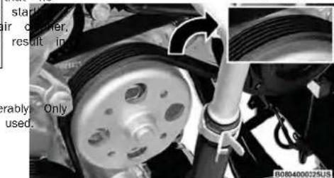
natural_image
Close-up of a car brake system with visible components and a close-up inset (no text or symbols)AccessoryBelt(SerpentineBelt)
Conditions that would require replacement: drive ● Belt chunking (one or more ribs has separated belt body) an, dis-Rib or belt wear temperabangitudinal belt cracking (cracks between two ardless Belt slips he moving above jumping (belt does not maintain correction on pulley) around Belt broken
NOTE: perfolently and correct problem before new belt is etent installed
- Noise (objectionable squeal, squeak, or rumble is heard or felt while drive belt is in operation).
AIR CONDITIONER MAINTENANCE
For best possible performance, your air conditioner should be checked and serviced by an authorized dealer at the start of each warm season. This service should include cleaning of the condenser fins and a performance test. Drive belt tension should also be checked at this time.
WARNING!
- Use only refrigerants and compressor lubricants approved by the manufacturer for your air conditioning system. Some unapproved refrigerants are flammable and can explode, injuring you. Other unapproved refrigerants or lubricants can cause free system to fail, requiring costly repairs. Refer to Warranty Information located online, for further warranty information.
The air conditioning system contains refrigerant under high pressure. To avoid risk of personal or damage to the system, adding refrigerant or any repair requiring lines to be disconnected should be done by an experienced technician.
8
CAUTION!
Do not use chemical flushes in your air system as the chemicals can damage your tioning components. Such damage is not co the New Vehicle Limited Warranty.
The cabin air filter is located in the fresh air 4Jin@pebehthe glove compartment door as far as possit the glove compartment. Perform the following proce-to-gain access to the cabin air filter compartment due to replace the filter: cover.
air gondt remove all contents from the glove compartment.
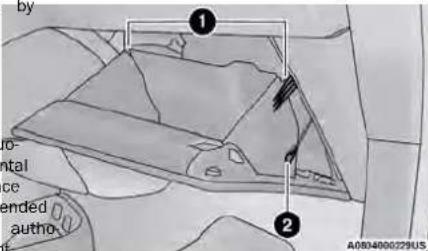
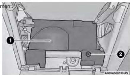
CabinAirFilterCompartmentCover
GloveCompartment
Refrigerant Recovery And Recycling—R-1234yf
R-1234yf Air Conditioning Refrigerant is a Hydrofluorooolefin (HFO) that is endorsed by the Environmental Protection Agency and is an ozone-friendly substance with a low global-warming potential. It is recommended that air conditioning service be performed by an authorized dealer using recovery and recycling equipment.
NOTE:
Use only manufacturer approved A/C system PAG pressor oil, and refrigerants.
CabinAirFilter
WARNING!
Do not remove the cabin air filter while the running, or while the ignition is in the ACC mode. With the cabin air filter removed and blower operating, the blower can contact hand may propel dirt and debris into your eyes, personal injury.
1 com- Glove Compartment Travel Stops 2 - Glove Compartment Tension Tether Clip
- Open the glove compartment door partially, I extra slack on the glove compartment tension tether. Detach the glove compartment tension by sliding the black tension tether clip down, vhipping it out of the slot on the side of
And There are glove compartment travel stops on sultiniden of the glove compartment door. To relea
1 — Compartment Cover 2 — Compartment Snap
-
Pry up the lid of each individual compartment snap and detach it from the rest of the snap. There is leaving small space on the side of each snap to use for separating the lid from the snap. Once detached, tether remove the rest of the snap completely from the and compartment cover.
-
After removing the snaps, lift up the compartment cover to gain access to the fresh air inlet.
them, push inward on each travel stop, and pull the glove compartment door down until the travel stops pass clear of their hooking points.
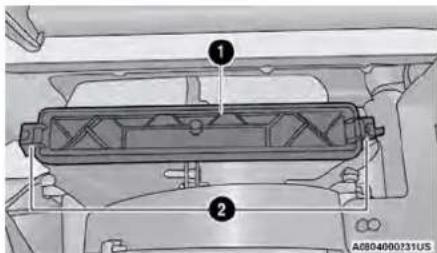
CabinAirFilterCover
1 - Filter Cover
2 - Retaining Tabs
- Remove the filter cover by prying back retaining tabs from their hooking points, a pulling the filter cover out to expose the filter. Remove the air filter by pulling it the housing.
- Install the new air filter with the arrow pointing toward the floor.
CAUTION!
The cabin air filter is identified with an a cate airflow direction through the filter. Fail properly install the filter will result in the replace it more often.
- Close the cabin air filter compartment cover, WINDSHIELD WIPER BLADES reinsert the snaps into their slots. Push the snap lids until fully attached. Clean the rubber edges of the wiper blades and the windshield periodically with a sponge or soft cloth and
- Push the glove compartment door to the near mild nonabrasive cleaner. This will remove accumula-
closed position to reengage the glove compartments of salt or road film.
ment travel stops. Finally, pull the glove compartment tension tether clip down and slide it back into may cause deterioration of the wiper blades. Always the slot on the side of the glove compartment door, use washer fluid when using the wipers to remove sa or dirt from a dry windshield.
BODY LURRICATION
Avoid using the wiper blades to remove frost or ice Locks and all body pivot points, including such items. The windshield. Keep the blade rubber out of contact seat tracks, door hinge pivot points and rollers, v/gate petroleum products such as engine oil, gasoline, tailgate, decklid, sliding doors and hood hinges, should be lubricated periodically. Use a lithium-based grease.
such as Mopar® Spray White Lube to ensure qNOTE:
easy operation and to protect against rust and water, expectancy of wiper blades varies depending on. Prior to the application of any lubricant, the geographical area and frequency of use. If chattering, it should be wiped clean to remove dust and grift marks; water lines or wet spots are present, clean then lubricating, excess oil and grease should be wiper blades or replace as necessary. Removed. Particular attention should also be given to labeled cracking components to ensure proper function. The wiper blades and wiper arms should be inspected periodically, not just when wiper performance problems when performing other underhood services, the hood latch release mechanism, and safety catch should be experienced. This inspection should include the following points:
The external lock cylinders should be lubricated twice a year, preferably in the Autumn and Spring. Apply a foreign material amount of a high quality lubricant, such as Mopar@Hardening or cracking Lock cylinder Lubricant directly into the lock cylinder Deformation or fatigue
If a wiper blade or wiper arm is damaged, replace t affected wiper arm or blade with a new unit. Do not attempt to repair a wiper arm or blade that is dama
- Once the filter is replaced, reinstall the filter cover, making sure the retaining tabs are fully secured into their housings.

FrontWiperBladeRemoval/Installation
CAUTION!
Do not allow the wiper arm to spring back glass without the wiper blade in place or may be damaged.
- Lift the wiper arm to raise the wiper blade glass, until the wiper arm is in the full up
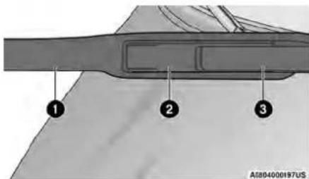
WiperBladeWithReleaseTabInLockedPosition
1 — Wiper Blade 2 — Release Tab 3 — Wiper Arm
- To disengage the wiper blade from the wiper arm, flip up the release tab on the wiper blade and while holding the wiper arm with one hand, slide the wiper blade down towards the base of the wiper arm.
gainst the
glass
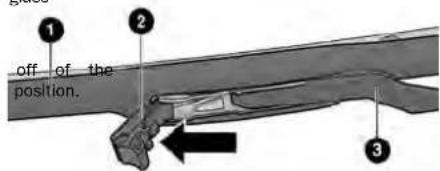
ADIB4000198US
WiperBladeWithReleaseTabInUnlockedPosition
1 - Wiper Blade
2 - Release Tab
3 - Wiper Arm
- With the wiper blade disengaged, remove blade from the wiper arm by holding the with one hand and separating the wiper by the wiper arm with the other hand (move blade toward the right side of the vehicle rate the wiper blade from the wiper arm).
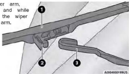
WiperBladeRemovedFromWiperArm
1 - Wiper Blade
2 - Release Tab
3 - Wiper Arm
-
Gently lower the wiper arm onto the glass. InstallingTheFrontWipers
-
Lift the wiper arm off of the glass, until the wiper arm is in the full up position.
piper Pavilion the wiper blade near the hook on the tip le them wiper arm with the wiper release tab open an the taperblade side of the wiper facing up and away I to slide-windshield.
- Insert the hook on the tip of the arm through the opening in the wiper blade under the release tab.
- Slide the wiper blade up into the hook on the wiper arm and rotate the wiper blade until it is flush again the wiper arm. Fold down the latch release tab and snap it into its locked position. Latch engagement will be accompanied by an audible click.
- Gently lower the wiper blade onto the glass.
RearWiperBladeRemoval/Installation
- Lift the rear wiper arm pivot cap away from the glass
to allow the rear wiper blade to be raised off of the glass.
NOTE:
The rear wiper arm cannot be fully raised off the glass unless the wiper arm pivot cap is unsnapped first. Attempting to fully raise the rear wiper arm without unsnapping the wiper arm pivot cap may damage the vehicle.
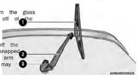
WiperBladeInFoldedOutPosition
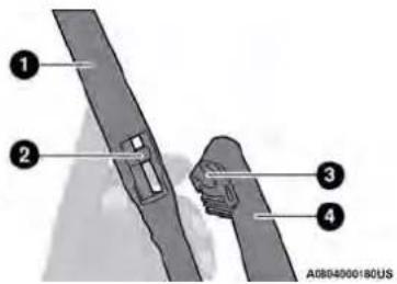
WiperBladeRemovedFromWiperArm
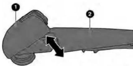
natural_image
Anatomical illustration of a biological structure with numbered parts and an arrow indicating a specific region (no text or labels present)WiperPivotCapInUnlockedPosition
1 - Wiper Arm Pivot Cap
2 - Wiper Arm
- Lift the rear wiper arm fully off the glass.
1 - Wiper Blade
2 - Wiper Arm
3 - Wiper Arm Pivot Cap
1 - Wiper Blade
2 - Wiper Blade Pivot Pin
3 - Wiper Arm Receptacle
4 — Wiper Arm
- To remove the wiper blade from the wiper arm, grab
the bottom end of the wiper blade nearest t5. wiperly lower the tip of the wiper arm onto the g
arm with your right hand. With your left hand, hold InstallingTheRearWiper
the wiper arm as you pull the wiper blade away from
the wiper arm past its stop far enough to unsnap the rear wiper arm pivot cap away from the
the wiper blade pivot pin from the receptacle on the end of the wiper arm.
NOTE:
NOTE:
Resistance will be accompanied by an audible snap. The rear wiper arm cannot be fully raised
- Still holding the bottom end of the wiper blade first. Attempting to fully raise the rear wiper arm
move the wiper blade upward and away from the without unsnapping the wiper arm pivot cap may
wiper arm to disengage.
-
Lift the rear wiper arm fully off the glass.
-
Insert the wiper blade pivot pin into the open the end of the wiper arm. Grab the bottom the wiper arm with one hand, and press the blade flush with the wiper arm until it snaps place.
- Lower the wiper blade onto the glass and wiper arm pivot cap back into place.
EXHAUST SYSTEM
The best protection against carbon monoxide entry the vehicle body is a properly maintained engine exhaust system.
If you notice a change in the sound of the exh tem; or if exhaust fumes can be detected inside vehicle; or when the underside or rear of the ve damaged; have an authorized technician inspect the complete exhaust system and adjacent body areas broken, damaged, deteriorated, or mispositioned parts Open seams or loose connections could permit exh
fumes to seep into the passenger compartment. In addition, have the exhaust system inspected each vehicle is raised for lubrication or oil changes. Replace as required.
WARNING!
- Exhaust gases can injure or kill. They contain bon monoxide (CO), which is colorless and od less. Breathing it can make you unconscious can eventually poison you. To avoid breathing page 160 for further information.
- A hot exhaust system can start a fire if your over materials that can burn, such as grass leaves, and those items come into contact with your exhaust system. Do not park or operate vehicle in areas where your exhaust system can contact anything that can burn.
| ening on end of CAUTION! |
| • wiper the catalytic converter requires the use of unleaded fuel only. Leaded gasoline will do the effectiveness of the catalyst as an e map control device and may seriously reduce e performance and cause serious damage to engine. |
| • Damage to the catalytic converter can res into vehicle is not kept in proper operating o the event of engine malfunction, particular ing engine misfire or other apparent loss shaust sys- mance, have your vehicle serviced promptly the continued operation of your vehicle with a s vehicle is malfunction could cause the converter to e resulting in possible damage to the conve for vehicle. |
under normal operating conditions, the catalytic vector will not require maintenance. However, it is important to keep the engine properly tuned to proper catalyst operation and prevent possible ca damage.
NOTE:
Intentional tampering with emissions control systems can result in civil penalties being assessed against and unusual situations involving grossly malfunctioning engine operation, a scorching odor may suggest s and abnormal catalyst overheating. If this occurs, the vehicle, turn off the engine and allow it to vice, including a tune-up to the manufacturer spe tions, should be obtained immediately.
To minimize the possibility of catalytic converter damage:
- Do not interrupt the ignition when the transmission toy is in gear and the vehicle is in motion.
siondo not try to start the vehicle by pushing or towine the vehicle.
Do not idle the engine with any ignition component: disconnected or removed, such as during diagnostic if testing, or for prolonged periods during very rough conditions or malfunctioning operating conditions.
COOLING SYSTEM
heat,
WARNING!
- you or others can be badly burned by hot engine coolant (antifreeze) or steam from your radiator. If you see or hear steam coming from under the hood, do not open the hood until the radiator has had time to cool. Never open a cooling system pressure cap when the radiator or coolant bottle is
- Keep hands, tools, clothing, and jewelry away from the radiator cooling fan when the hood is raised. The fan starts automatically and may start at any time, whether the engine is running or not.
- When working near the radiator cooling fan, dis- ng connect the fan motor lead or turn the ignition to severe the OFF mode. The fan is temperature controlled stop and can start at any time the ignition is in the cool Ser- mode. deficata
EngineCoolantChecks
SelectionOfCoolant
Check the engine coolant (antifreeze) protection eFery further information page 226.
12 months (before the onset of freezing weather, where
applicable). If the engine coolant is dirty, the system
should be drained, flushed, and refilled with fresh
Organic Additive Technology (OAT) coolant (conforming specified to MS.90032) by an authorized dealer. Check the spot coolant, may result in engine damage and may be important to use the same engine coolant (OAT could decrease corrosion protection. OAT engine coolant is different and should not be mixed with Hybrid conforming to MS.90032) throughout the life of your vehicle. Organic Additive Technology (HOAT) engine coolant
Check the engine cooling system hoses for brittle lubricity, specifically, compared to the power of the engine coolant that meets the requirements of the ber, cracking, tears, cuts, and tightness of the concrean emergency, the cooling system will need to be added to the coolant recovery bottle and radiator. Insulated, flushed, and refilled with fresh OAT coolant engine coolant:
the entire system for leaks. DO NOT REMOVE THE (conforming to MS.90032), by an authorized dealer. We recommend using Mopar® Antifreeze/Coolant COOLANT PRESSURE CAP WHEN THE COOLING SYSTEM is soon as possible. 10 Year/150,000 Mile (240,000 km) Formula OAT IS HOT.
CoolingSystem—Drain, FlushAndRefill
NOTE:
Some vehicles require special tools to add coolant early. Failure to fill these systems properly could be severe internal engine damage. If any coolant is not to be added to the system please contact an au dealer.
If the engine coolant (antifreeze) is dirty or contain visible sediment, have an authorized dealer clean a flush with Organic Additive Technology (OAT) coolant (conforming to MS.90032).
For the proper maintenance intervalage 184.
- Do not use water alone or alcohol-based electric coolant products. Do not use additional rust tors or anti-rust products, as they may not patible with the radiator engine coolant and plug the radiator.
de this to vehicle has not been designed for use needed glycol-based engine coolant. Use of pro-authorized glycol-based engine coolant is not recommended.
Some vehicles require special tools to add properly. Failure to fill these systems properly lead to severe internal engine damage. If a ant is needed to be added to the system tact an authorized dealer.
AddingCoolant
Your vehicle has been built with an improved engine coolant (OAT coolant conforming to MS.90032) that allows extended maintenance intervals. This engine
coolant (antifreeze) can be used up to ten years or 150,000 miles (240,000 km) before replacement. To prevent reducing this extended maintenance period, it is important to use the same engine coolant (OAT coolant is conforming to MS.90032) throughout the life of
your vehicle.
Please review these recommendations for using OAT engine coolant that meets the requirements of the manufacturer Material Standard MS.90032. When adding engine coolant:
ealeWe recommend using Mopar® Antifreeze/Coolant 10 Year/150,000 Mile (240,000 km) Formula OAT that meets the requirements of the manufacturer Material Standard MS.90032.
- Min-a minimum solution of 50% OAT engine coolant may that meets the requirements of the manufacturer Material Standard MS.90032 and distilled water. Use higher concentrations (not to exceed 70%) if with pro- temperatures below -34°F (-37°C) are anticipated. Please contact an authorized dealer for assistance.
- Use only high purity water such as distilled water when mixing the water/engine cooling solution. The use of lower quality water with reduced colour amount of corrosion protection in the engine cooling system. - Please con-
NOTE:
- It is the owner's responsibility to maintain the proper level of protection against freezing according to the temperatures occurring in the area where the vehicle is operated.
- Some vehicles require special tools to add co properly. Failure to fill these systems properly lead to severe internal engine damage. If any ant is needed to be added to the system, I contact an authorized dealer.
- Mixing engine coolant types is not recommended and can result in cooling system damage. If and OAT coolant are mixed in an emergency, an authorized dealer drain, flush, and refill with coolant (conforming to MS.90032) as soon as possible.
CoolingSystemPressureCap
The cap must be fully tightened to prevent low engine coolant (antifreeze), and to ensure that coolant will return to the radiator from the co-expansion bottle/recovery tank (if equipped).
The cap should be inspected and cleaned if accumulation of foreign material on the sealing surfaces.
WARNING!
- Do not open hot engine cooling system. engine coolant (antifreeze) when the engine overheated. Do not loosen or remove the cool an overheated engine. Heat causes p to build-up in the cooling system. To pre ing or injury, do not remove the pressure the system is hot or under pressure.
- Do not use a pressure cap other than specified for your vehicle. Personal injury damage may result.
DisposalOfUsedCoolant
could
Used ethylene glycol-based coolant (antifreeze)
cool-
regulated substance requiring proper disposal
please
with your local authorities to determine the rules for your community. To prevent ingesti
edials or children, do not store ethylene gly-
tOHINT in open containers or allow it to
phodates on the ground. If ingested by a d
theeIOATEmergency assistance immediately. Clean
ground spills immediately.
CoolantLevel
The coolant expansion bottle provides a quick method for determining that the coolant level adequate. With the engine off and cold, the coolant (antifreeze) in the bottle should be "MAX" and "MIN" lines marked on the bott
As long as the engine operating temperature, the coolant bottle need only be checked month.
When additional coolant is needed to maintain proper level, it should be added to the coDo not overfill.
^r See ^add_an authorized dealer for service.
CoolingSystemNotes
ure seald: NOTE:
can while When the vehicle is stopped after a few miles/ kilometers of operation, you may observe vapor coming the room the front of the engine compartment. This is nor- or ending a result of moisture from rain, snow, or high humidity accumulating on the radiator and being vapor- ized when the thermostat opens, allowing hot engine coolant (antifreeze) to enter the radiator.
If an examination of your engine compartment shows no evidence of radiator or hose leaks, the vehicle may be safely driven. The vapor will soon dissipate.
Do not overfill the coolant expansion bottle.
By Olmeck the coolant freeze point in the radiator and
used the coolant expansion bottle. If engine coolant in needs to be added, the contents of the coolant or expansion bottle must also be protected against freezing.
- If frequent engine coolant additions are required, the cooling system should be pressure tested for leaks.
Maintain engine coolant concentration at a mini-
mum of 50% OAT coolant (conforming to MS.90032)
level and distilled water for proper corrosion protection of
very you the engine which contains aluminum components.
- Make sure that the coolant expansion bottle oversatisfac-hoses are not kinked or obstructed.
Once a keep the front of the radiator clean. If your vehicle equipped with air conditioning, keep the front of the condenser clean.
- Do not change the thermostat for Summer or Winter operation. If replacement is ever necessary, install ONLY the correct type thermostat. Other designs may result in unsatisfactory engine cooling performance, poor gas mileage, and increased emissions.
BRAKE SYSTEM
In order to ensure brake system performance, all system components should be inspected periodically. For the proper maintenance intervalage 184.
WARNING!
Riding the brakes can lead to brake failure a bly a collision. Driving with your foot resting on the brake pedal can result in abnormally brake temperatures, excessive lining wear, and sible brake damage. You would not have your braking capacity in an emergency.
BrakeMasterCylinder
The fluid in the master cylinder should be checked when performing under hood services or immediate the Brake Warning Light is illuminated.
Be sure to clean the top of the master cylinder before removing the cap. If necessary, add fluid the fluid level up to the requirements described brake fluid reservoir. With disc brakes, fluid level expected to fall as the brake pads wear. Brake level should be checked when pads are replaced ever, low fluid level may be caused by a leak checkup may be needed.
Use only manufacturer recommended brake fluid page 227.
WARNING!
- brake
Use only manufacturer recommended brake to page 227. Using the wrong type of brake can severely damage your brake system and impair its performance. The proper type of fluid for your vehicle is also identified on nal factory installed hydraulic master cylinder or possi reservoir.
To avoid contamination from foreign matter, moisture, use only new brake fluid or fluid been in a tightly closed container. Keep the cylinder reservoir cap secured at all times, fluid in an open container absorbs moisture the air resulting in a lower boiling point. Cause it to boil unexpectedly during hard longed braking, resulting in sudden brake failure. This could result in a collision.
Overfilling the brake fluid reservoir can resu spilling brake fluid on hot engine parts, ca the brake fluid to catch fire. Brake fluid damage painted and vinyl surfaces, care sh taken to avoid its contact with these surfa can be do not allow petroleum-based fluid to conta fluid. Brake fluid. Brake seal components cou damaged, causing partial or complete brake ure. This could result in a collision.
AUTOMATIC TRANSMISSION
fluidSpecialAdditives
The manufacturer strongly recommends against using any special additives in the transmission. Automatic brake transmission Fluid (ATF) is an engineered product and its performance may be impaired by supplemental additives. Therefore, do not add any fluid additives to the transmission. Avoid using transmission sealers as they or may adversely affect seals. d that has
| the Brake | masterCAUTION! |
| e from This or failure | DO not use chemical flushes in your trans- the chemicals can damage your transmission Rents. Such damage is not covered by the Vehicle Limited Warranty. |
FluidLevelCheck
can also The fluid level is preset at the factory and does not should be required adjustment under normal operating conditions. Routine fluid level checks are not required; therefore aminate transmission has no dipstick. An authorized dealer fluid can check your transmission fluid level using fairs service tools. If you notice fluid leakage or the malfunction, visit an authorized dealer immediat have the transmission fluid level checked. Operating the vehicle with an improper fluid level can cause severe transmission damage.
CAUTION!
If a transmission fluid leak occurs, visit an aut dealer immediately. Severe transmission damage may occur. An authorized dealer has the proper to adjust the fluid level accurately.
FluidAndFilterChanges
Under normal operating conditions, the fluid install the factory will provide satisfactory lubrication for life of the vehicle.
Routine fluid and filter changes are not required, ever, change the fluid and filter if the fluid be contaminated (with water, etc.), or if the transmis disassembled for any reason.
SelectionOfLubricant
It is important to use the proper transmission f ensure optimum transmission performance and life. Use only the manufacturer specified transmission page 227. It is important to maintain the t sion fluid at the correct level using the recomm fluid.
NOTE:
No chemical flushes should be used in any tran sion; only the approved lubricant should be used
CAUTION!
Using a transmission fluid other than manual recommended fluid may cause deterioration in mission shift quality and/or torque converter page 227.
FUSES
autiGeneralInformation
tools
WARNING!
- When replacing a blown fuse, always use priate replacement fuse with the same an as the original fuse. Never replace a fus ed another fuse of higher amp rating. Never theblown fuse with metal wires or any other Do not place a fuse inside a circuit br HW. vice versa. Failure to use proper fuse result in serious personal injury, fire and/ some damage.
- Before replacing a fuse, make sure that tion is off and that all the other service switched off and/or disengaged.
If to the replaced fuse blows again, contact rized dealer.
widif a general protection fuse for safety system, braking system, braking system), power unit (endengine system, transmission system) or st System blows, contact an authorized dealer
an app p rating with replace material aker cavi may
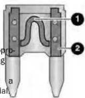
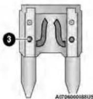
BladeFuses
1 — Fuse Element the 2igm- Blade Fuse with a good/functional fuse element s are — Blade Fuse with a bad/not functional fuse element (blown fuse)
an autho-
UnderhoodFuses
The Power Distribution Center (PDC) is located in the engine compartment near the battery. This center contains cartridge fuses, mini-fuses, micro-fuses, circuit breakers and relays. A label that identifies each component is printed on the inside of the cover.
Before any procedure is done on the PDC, make sure engine is turned off.
The fuses protect electrical systems against e transmis current. used
When a device does not work, you must cl element Inside the blade fuse for a break/m Also, please be aware that using power outl acture extended periods of time with the engine of
1 trains- vehicle battery discharge. shudder
Remove the cover by unlatching the two locks located at each side of the PDC cover, avoid using screwdrive or any other tool to remove the cover, since they may apply excessive force and result in a broken/damaged may part.
After service is done, secure the cover with its two locks.
CAUTION!
When installing the Power Distribution Center is important to ensure the cover is properly tioned and fully latched. Failure to do so water to get into the Power Distribution Ce possibly result in an electrical system failure
NOTE:
The function and amperage of the following fuses are different, depending on vehicle trim level and content. cover; it post- may allow ter and
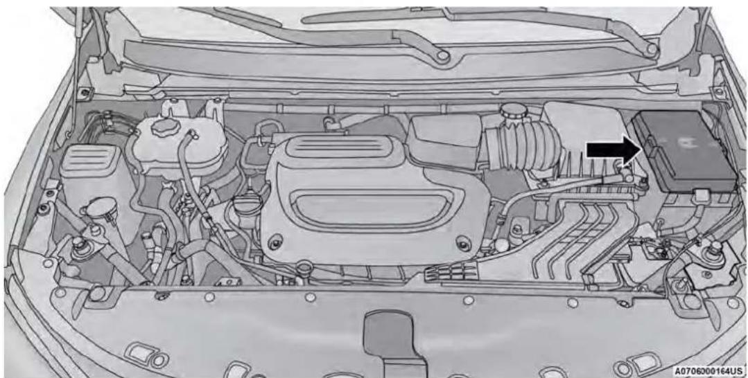
natural_image
Interior view of a car's engine bay with visible components and a black arrow indicating a specific component (no text or symbols present)PowerDistributionCenter
| CavityCartridgeFuseBladeFuseDescription | |||
| *IfEquipped | |||
| F06 - - Not Used | |||
| F07 - 25 Amp Clear Ignition Coil/Fuel Injector | |||
| F08 - - Not Used | |||
| F09 - 25 Amp Clear Amplifier/Active Noise Control * | |||
| F10 - - Not Used | |||
| F11 - - Not Used | |||
| F12 - 5 Amp Tan Battery Sensor (IBS) | |||
| F13 - 10 Amp Red ECM (S)* | |||
| F14 - 10 Amp Red ECM | |||
| F15 | 40 Amp Green | - | CBC Feed #3 (Power Locks) |
| F16 - | 20 Amp Yellow | ECM | |
| F17 | 30 Amp Pink | - | Starter |
| F18 | 40 Amp Green | - | CBC Feed #4 (Exterior Lighting #1) |
| F19 | 25 Amp Clear | - | 2nd Row Folding Seats Solenoid LT * |
| F20 - 10 Amp Red A/C Compressor Clutch | |||
| F21 | 25 Amp Clear - | 2nd Row Folding Seat | Solenoid RT * |
| F22 - - Not Used | |||
| F23 - - Not used | |||
| F24 - | 20 Amp Yellow | RR Wiper | |
| F25 - 10 Amp Red | Hands-free Door Mod / Active Shutter/ PWR Mirror / VRM | ||
| F26 | 40 Amp Green | - | Front HVAC Blower Motor |
| F27 | 25 Amp Clear - | RR Slide Door Module-RT * | |
| F28 - 10 Amp Red | Diagnostic Port / USB+ (IP) / Vic Port / Overhead DVD Player (After | ||
Grill deo USB market)
| CavityCartridgeFuseBladeFuseDescription | ||||
| *IfEquipped | ||||
| F29 - - Not Used | ||||
| F30 - 15 Amp Blue Media HUB / PWR Lumbar * | ||||
| F31 - - Not Used | ||||
| F32 20 Amp Blue - ECM | ||||
| F33 30 Amp Pink - Power Liftgate * | ||||
| F34 25 Amp Clear - RR Door Module-LT * | ||||
| F35 25 Amp Clear - Sunroof * | ||||
| F36 - - Not Used | ||||
| F37 | 40 Amp Green | - | CBC / Exterior Lights | |
| F38 | 60 Amp Yellow | - | Vacuum Cleaner * | |
| F39 25 Amp Clear - Rear HVAC Blower Motor | ||||
| F40 - - Not Used | ||||
| F41 - - Not Used | ||||
| F42 | 40 Amp Green | - | Folding Seat Module * | |
| F43 - | 20 Amp Yellow | Fuel Pump Motor | ||
| F44 | 30 Amp Pink - CBC / Interior Lights | |||
| F45 30 Amp Pink - Power Inverter * | ||||
| F46 30 Amp Pink - Driver Door Module | ||||
| F47 | 30 Amp Pink - Passenger Door Module | |||
| F48 - - Not Used | ||||
| F49 25 Amp Clear - RR Sliding Door Module-LT * | ||||
| F50 25 Amp Clear - RR Door Module-RT * | ||||
| F51 | 30 Amp Pink - Front Wiper | |||
| F52 30 Amp Pink - Brake Vacuum Pump | ||||
| F53 - - Not Used | ||||
| F54 40 Amp Green | - ESP-ECU & Valves | |||
| F55 - 15 Amp Blue RF HUB/ KIN / ESL / DVD | ||||
| F56 - 10 Amp Red | Front & Rear HVAC Control / OCM ESP / ESC | |||
| F57 - - Not Used | ||||
| F58 - 10 Amp Red | Drivetrain Control Mod / Power Tr Unit * | |||
| F59 | 30 Amp Pink - | Trailer Tow Receptacle * | ||
| F60 - 20 Amp Yellow | Rear Cargo APO | |||
| F61 - 20 Amp Yellow | Trailer Tow Right Stop/Turn * | |||
| F62 - 20 Amp Yellow | Power Transfer Unit * | |||
| F63 - 20 Amp Yellow | Trailer Tow Left Stop/Turn * | |||
| F64 - 15 Amp Blue | RT HID Headlamp * | |||
| F65 - - Not Used | ||||
| F66 - 15 Amp Blue | Cluster | |||
| F67 - 10 Amp Red | DASM / Parktronic / HALF | |||
| F68 - - Not Used | ||||
| F69 - - Not Used | ||||
| F70 - - Not Used | ||||
| F71 | - 20 Amp Yellow | Horn | ||
| F72 - 10 Amp Red | Heated Mirrors * | |||
| F73 | 30 Amp Pink - | Rear Defroster (EBL) | ||
| F74 | 20 Amp Blue - | Trailer Tow Back-up Lights * | ||
| F75 - | 5 Amp Tan | Overhead Console / RR ISC | ||
| F76 | - 20 Amp Yellow | Uconnect / Center Display / Telematics | ||
/ ESL
ansfer
| CavityCartridgeFuseBladeFuseDescription | |||
| *IfEquipped | |||
| F77 - 10 Amp Red | RR Entertainment / Media Hub / Rain Sensor / Sunroof / RR V/ Overhead DVD Player / Int Mot Camera / Wireless Charging Pad | ||
| F78 - 15 Amp Blue TCM (ZF) / E-Shifter / Cluster | |||
| F79 - 10 Amp Red ICS / HVAC / EPB SW / Strg | Column Cntrl | ||
| F80 - - Not Used | |||
| F81 - - Not Used | |||
| F82 - - Not Used | |||
| F83 | 20 Amp Blue - TT Park Lights * | ||
| 30 Amp Pink - Headlamp Washer Pump * | |||
| F84 30 Amp Pink - Drivetrain | Control MOD * | ||
| F85 - | 20 Amp Yellow | Cigar Lighter | |
| F86 - - Not Used | |||
| F87 - - Not Used | |||
| F88 - | 20 Amp Yellow | Front Heated Seats | * |
| F89 - | 20 Amp Yellow | Rear Heated Seats | * |
| F90 - - Not Used | |||
| F91 - 15 Amp Blue | Front Ventilated Seats / Heated St Wheel * | ||
| F92 - | 5 Amp Tan | Security Gateway | |
| F93 - - Not Used | |||
| F94 | 40 Amp Green | - | ESC Motor Pump |
| F95A | - 10 Amp Red | USB IP (Run/ACC) | |
| F95B | - 10 Amp Red | Selectable Fuse Location - USB (Direct B+) | |
| F96 - 10 Amp Red | Airbag | ||
USB (S) ew Mirror
IP
| CavityCartridgeFuseBladeFuseDescription | |||
| *IfEquipped | |||
| F97 - 10 Amp Red Airbag | |||
| F98 - 15 Amp Blue Left HID Headlamp * | |||
| F99 30 Amp Pink - Trailer Tow Electric Brake Mod | * | ||
| F100 - 10 Amp Red | Headlamp Level / RR Camera / Blindspot / Humidity Snsr / In Car Temp Snsr / Headlamp SW * | ||
| CircuitBreakers | |||
| CB1 25 Amp | Power Seats (Driver) | ||
| CB2 | 25 Amp ** | Power Seats (Pass) | |
| CB3 25 Amp | FRT PWR Window W/O Door Nodes + RR PWR Window Lockout | ||
** 30 Amp mini fuse is substituted for 25 Amp Circuit Breaker.
BULB REPLACEMENT
Replacement Bulbs, Names, And Part Numbers
In the instance a bulb needs to be replaced, this section includes bulb description and replacement part numbers. Some of the inside bulbs are brass or glass-wedge base. Aluminum base bulbs are not approved.
NOTE:
See an authorized dealer for LED bulb replacement.
| InteriorBulbs | |
| Lamps | BulbNumber |
| Center & Rear Dome Lamp | LED |
| Center & Rear Reading Lamps | LED |
| Front Door Courtesy Lamp | LED |
| Front Header Reading Lamps - If Equipped | LED |
| LampsBulbNumber | |
| Instrument Cluster Lamps LED | |
| Liftgate Lamp(s) LED | |
| Overhead Console Reading Lamps LED | |
| Removable Console Lamp - If Equipped LED | |
| Visor Vanity Lamps 6501966 | |
| ExteriorBulbs | |
| LampsBulbNumber | |
| Halogen Head Lamp | Reflector Low Beam - H11LLReflector High Beam - 9005LL |
| Front Turn Signal Lamp PWY24WNA | |
| Front Side Marker Lamp W3W | |
| Front Park Lamp PWY24WNA | |
| Center High Mounted Stop Lamp (CHMSL) LED (Serviced at an authorized dealer) | |
| Stop/Turn Signal Lamp W21/5WLL | |
| Rear Tail/Side Marker Lamp | Rear Tail - Body Side - W21/5WLLRear Tail - Liftgate - W5WLL |
| Rear Side Marker Lamp | W3W |
| Backup Lamp | W21W |
| License Lamp | LED |
ReplacingExteriorBulbs
FRONTTURNSIGNALLAMP
See the following steps to replace:
- Open the hood.
- Twist the front turn signal lamp socket assembly counterclockwise, and then remove the front turn signal lamp assembly from the lamp housing.
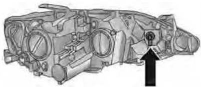
natural_image
Technical illustration of an internal combustion engine component with a black arrow pointing to a specific part (no text or symbols present)A0705000163US
FrontTurnSignalLampSocket
- Pull the bulb out of the socket and insert the replacement bulb.
- Install the front turn signal lamp socket assembly into the housing, and rotate the front turn signal lamp socket clockwise to lock it in place.
FRONTANDREARSIDEMARKERLAMPS
See the following steps to replace:
- Remove the three fasteners from the inner liner and carefully peel back liner for access.
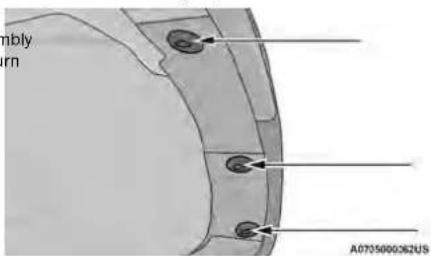
InnerWheelLinerFasteners
-
Firmly grab the front side marker lamp socket and rotate a quarter turn counterclockwise to remove it from the lamp assembly.
-
Remove bulb from the front side marker lamp socket and replace with a new bulb.
- Install front side marker lamp socket in lamp assemble and rotate a quarter turn clockwise to lock into place.
- Position the inner wheel liner in place and install three fasteners.
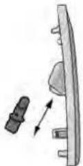
A0705000368U5
FrontSideMarkerLampBulbRemoval
TIRES
TIRE SAFETY INFORMATION
Tire safety information will cover aspects of the ing information: Tire Markings, Tire Identification bers, Tire Terminology and Definitions, Tire Press and Tire Loading.
TireMarkings
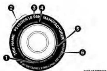
TireMarkings
NOTE:
- P (Passenger) — Metric tire sizing is based on US design standards. P-Metric tires have the letter "P" molded into the sidewall preceding the size designation. Example: P215/65R15 95H.
- European — Metric tire sizing is based on European design standards. Tires designed to this standard have the tire size molded into the sidewall beginning with the section width. The letter "P" is absent from this tire size designation. Example: 215/65R15 96H.
- LT (Light Truck) — Metric tire sizing is based on US design standards. The size designation for LT-Metric tires is the same as for P-Metric tires except for the letters "LT" that are molded into the sidewall preceding the size designation. Example: LT235/85R16.
- Temporary spare tires are designed for temporary emergency use only. Temporary high pressure compact spare tires have the letter "T" or "S" molded into the sidewall preceding the size designation. Example: T145/80D18 103M.
- High flotation tire sizing is based on US design standards and it begins with the tire diameter molded (TIN) the sidewall. Example: 31x10.5 R15 LT.
1 – US DOT Safety Standards Code
2 - Size Designation
3 - Service Description
4 - Maximum Load
5 - Maximum Pressure
6 — Treadwear, Traction and Tempera-
ture Grades
TIRESIZINGCHART
| EXAMPLE: |
| ExampleSizeDesignation:P215/65R15XL95H,215/65R1596H,LT235/85R16C,T145/80D18103M,31x10.5R15LT |
| P= Passenger car tire size based on US design standards, or"...blank..."= Passenger car tire based on European design standards, orLT= Light truck tire based on US design standards, orTor S= Temporary spare tire or31= Overall diameter in inches (in)215,235,145= Section width in millimeters (mm)65,85,80= Aspect ratio in percent (%)Ratio of section height to section width of tire, or10.5= Section width in inches (in) |
| R= Construction code"R" means radial construction, or"D" means diagonal or bias construction |
| 15,16,18= Rim diameter in inches (in) |
| ServiceDescription: |
| 95= Load IndexA numerical code associated with the maximum load a tire can carry |
| H= Speed SymbolA symbol indicating the range of speeds at which a tire can carry a load corresponding to its load index under certain operating conditionsThe maximum speed corresponding to the speed symbol should only be achieved under specified operating conditions (i.e., tire pressure, vehicle loading, road conditions, and posted speed limits) |
| LoadIdentification:Absence of the following load identification symbols on the sidewall of the tire indicates a Standard Load (SL) tire:XL= Extra load (or reinforced) tire, orLL= Light load tire orC, D, E, F, G = Load range associated with the maximum load a tire can carry at a specified pressure |
| MaximumLoad- Maximum load indicates the maximum load this tire is designed to carry |
| Maximum Pressure – Maximum pressure indicates the maximum permissible cold tire inflation pressure for this tire |
TireldentificationNumber(TIN)
The TIN may be found on one or both sides of the tire; however, the date code may only be on one side. Tires with white sidewalls will have the full TIN, including the date code, located on the white sidewall side of the tire. Look for the TIN on the outboard side of black sidewall tires as mounted on the vehicle. If the TIN is not found on the outboard side, then you will find it on the inboard side of the tire.
| EXAMPLE: |
| DOT MA L9 ABCD 0301 |
| DOT= Department of TransportationThis symbol certifies that the tire is in compliance with the US Department of Transportation tire safety standards and is approved for highway use |
| MA= Code representing the tire manufacturing location (two digits) |
| L9= Code representing the tire size (two digits) |
| ABCD= Code used by the tire manufacturer (one to four digits) |
| 03= Number representing the week in which the tire was manufactured (two digits)03 means the 3rd week |
| 01= Number representing the year in which the tire was manufactured (two digits)01 means the year 2001Prior to July 2000, tire manufacturers were only required to have one number to represent the year in which the tire was manufactured. Example: 031 could represent the 3rd week of 1981 or 1991 |
TireTerminologyAndDefinitions
| TermDefinition | |
| B-pillar | The vehicle B-pillar is the structural member of the body located behind the front door. |
| ColdTireInflationPressure | Cold tire inflation pressure is defined as the tire pressure after the vehicle has no least three hours, or driven less than 1 mlle (1.6 km) after sitting for a minimum pressure is measured in units of psi (pounds per square inch) or kPa (kilopascals). |
| MaximumInflationPressure | The maximum inflation pressure is the maximum permissible cold tire inflation pressure maximum inflation pressure is molded into the sidewall. |
| Recommended Cold Tire Inflation Pressure | The manufacturer recommended cold tire inflation pressure as shown on the tire placard. |
| TirePlacard | A label permanently attached to the vehicle describing the vehicle's loading capacity, ment tire sizes and the recommended cold tire inflation pressures. |
for this
the origin:
TireLoadingAndTirePressure
NOTE:
The proper cold tire inflation pressure is listed on the driver's side B-pillar or the rear edge of the driver's side door.
Check the inflation pressure of each tire, including the spare tire (if equipped), at least monthly and inflate to the recommended pressure for your vehicle.
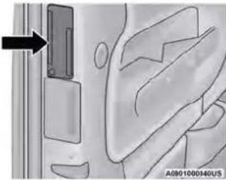
natural_image
Diagram of a door with a door lock and plastic panel, showing no text or symbolsExampleTirePlacardLocation(Door)
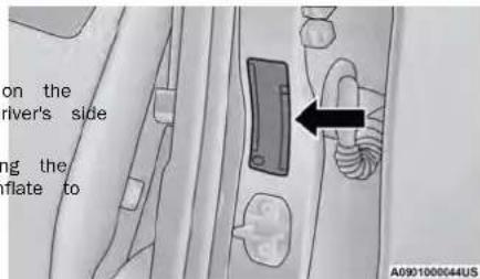
ExampleTirePlacardLocation(B-pllar)
TireAndLoadingInformationPlacard
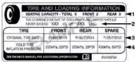
0116548
TireAndLoadingInformationPlacard
This placard tells you important information about the:
- Number of people that can be carried in the vehi
- Total weight your vehicle can carry.
- Tire size designed for your vehicle.
- Cold tire inflation pressures for the front, rear, and spare tires.
Loading
The vehicle maximum load on the tire must not exceed the load carrying capacity of the tire on your vehicle. You will not exceed the tire's load carrying capacity if you adhere to the loading conditions, tire size, and a tire inflation pressures specified on the Tire And Loading Information Placard in this mappage 90.
NOTE:
Under a maximum loaded vehicle condition, gross axle weight ratings (GAWRs) for the front and rear axles must not be exceeded.
For further information on GAWRs, vehicle loading, and trailer towing page 90.
To determine the maximum loading conditions of your vehicle, locate the statement "The combined weight of occupants and cargo should never exceed XXX kg or XXX lbs" on the Tire And Loading Information Placard. The combined weight of occupants, cargo/luggage and trailer tongue weight (if applicable) should never exceed the weight referenced here.
StepsForDeterminingCorrectLoad Limit—
(1) Locate the statement "The bined weight of occupants and should never exceed XXX kg or XXX lbs." on your vehicle's place.
(6) If your vehicle will be towing a trailer, load from your trailer will be transferred to your vehicle. Consult this manual to determine how this cargo reduces the available cargo and luggage load capacity of your vehicle. MetricExampleForLoadLimit
(2) Determine the combined we the driver and passengers that riding in your vehicle.
For example, if "XXX" amount equals 635 kg and there will be five 68 kg passengers in your vehicle, the amount of available cargo and luggage load capacity is 295 kg (635-340 (5x68) = 295 kg) as shown in step 4.
(3) Subtract the combined weigh the driver and passengers from or XXX lbs.
t NOTE: XXX kg If your vehicle will be towing a trailer, load from your trailer will be transferred to your vehicle. The following table shows examples on how to calculate total load, cargo/luggage, and towing capacities of your vehicle with varying seating configurations and number and size of occupants. This table is for illustration purposes only and may not be accurate for the seating and load carry capacity of your vehicle.
(4) The resulting figure equals available amount of cargo and load capacity. For example, if amount equals 1400 lbs. and will be five 150 lb passengers vehicle, the amount of available and luggage load capacity is 6 (1400-750 (5x150) = 650 lbs.)
in • Your following example, the combined weight of occupants and cargo should never exceed 865 lbs (392 kg). So Ibs.
(5) Determine the combined weight of luggage and cargo being loaded on the vehicle. That weight may not safely exceed the available cargo and luggage load capacity calculated in Step 4.
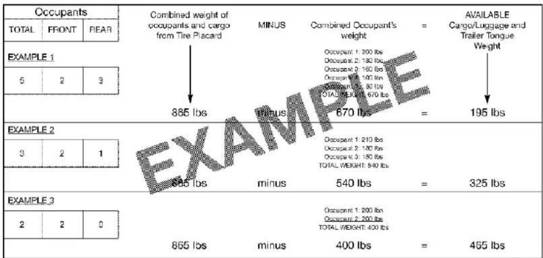
611a4d11
WARNING!
Overloading of your tires is dangerous. Overloading can cause tire failure, affect vehicle handling, and increase your stopping distance. Use tires of the recommended load capacity for your vehicle. Never overload them.
TIRES — GENERAL INFORMATION
Both underinflation and overinflation affect the st of the vehicle and can produce a feeling of s response or over responsiveness in the steering.
| ability luggish | CAUTION! |
| After inspecting or adjusting the tire pressur reinstall the valve stem cap. This will preve ture and dirt from entering the valve stem, cause damage the valve stem. | |
TirePressure
Proper tire inflation pressure is essential to the and satisfactory operation of your vehicle. Four areas are affected by improper tire pressure:
- Safety
- Fuel Economy
- Tread Wear
- Ride Comfort and Vehicle Stability
Safety
WARNING!
- Improperly inflated tires are dangerous and cause collisions.
- Underinflation increases tire flexing and car in overheating and tire failure.
- Overinflation reduces a tire's ability to crush shock. Objects on the road and chuckholes cause damage that result in tire failure.
- Overinflated or underinflated tires can affect vehicle handling and can fail suddenly, rest loss of vehicle control.
- Unequal tire pressures can cause steering lems. You could lose control of your veh
- Unequal tire pressures from one side of to the other can cause the vehicle to or right or left.
• Always drive with each tire inflated to the mended cold tire inflation pressure.
NOTE:
primary
- Unequal tire pressures from side to side may erratic and unpredictable steering response.
- Unequal tire pressure from side to side may the vehicle to drift left or right.
FuelEconomy
Underinflated tires will increase tire rolling resistant resulting in higher fuel consumption.
TreadWear
Improper cold tire inflation pressures can cause mal wear patterns and reduced tread life, resulti the need for earlier tire replacement.
RideComfortAndVehicleStability result
Proper tire inflation contributes to a comfortable Overinflation produces a jarring and uncomfortable can.
TireInflationPressures
The in proper cold tire inflation pressure is listed driver's side B-pillar or rear edge of the driver's door.
At least once a month:
- Check and adjust tire pressure with a good pocket-type pressure gauge. Do not make a judgment when determining proper inflation. Tire may look properly inflated even when they are underinflated.
- Inspect tires for signs of tire wear or visible damage.
Inflation pressures specified on the placard are always "cold tire inflation pressure". Cold tire inflation pressure is defined as the tire pressure after the vehicle has been driven for at least three hours, or driven less than 1 mile (1.6 km) after sitting for a minimum of three hours. The cold tire inflation pressure must not exceed the maximum inflation pressure molded into the tire sidewall.
Check tire pressures more often if subject to a wide range of outdoor temperatures, as tire pressures vary with temperature changes.
Tire. pressures change by approximately 1 psi (7 kPa) per 12°F (7°C) of air temperature change. Keep this mind when checking tire pressure inside a garage, especially in the Winter.
Example: If garage temperature = 68°F (20°C) and the outside temperature = 32°F (0°C) then the cold tire inflation pressure should be increased by 3 ppi (21 kPa), which equals 1 psi (7 kPa) for e-8 (7°C) for this outside temperature condition.
Tire pressure may increase from 2 to 6 psi (13 to 40 kPa) during operation. DO NOT reduce this normal pressure buildup or your tire pressure will be too low.

TirePressuresForHighSpeedOperation
TireRepair
TireSpinning
The manufacturer advocates driving at safe speeds ^f your tire becomes damaged, it may be repaired. When if stuck in mud, sand, snow, or ice conditions, do within posted speed limits. Where speed limits or meets the following criteria: not spin your vehicle's wheels above 30 mph (48 km
tions are such that the vehicle can be driven at. The tire has not been driven on when flat, or for longer than 30 seconds continuously without speeds, maintaining correct tire inflation pressure is. The damage is only on the tread section of your tire
very important. Increased tire pressure and reduced (sidewall damage is not repairable). vehicle loading may be required for high-speed vehicle operation. Refer to an authorized tire dealer or original operation. The puncture is no greater than 14 of an equipment vehicle dealer for recommended safe operating speeds, loading and cold tire inflation pressures. Result an authorized tire dealer for tire repairs additional information.
WARNING!
High speed driving with your vehicle under load is dangerous. The added strain on yo could cause them to fail. You could have collision. Do not drive a vehicle loaded to mum capacity at continuous speeds above (120 km/h).
Damaged Run Flat tires, or Run Flat tires that experienced a loss of pressure should be replaced by immediately with another Run Flat tire of identical tire service description (Load Index and Speed a serial) Replace the tire pressure sensor as well as the designed to be reused.
75 mph
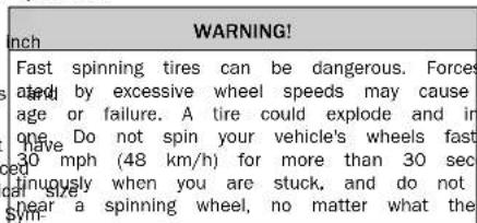
as it is not
TreadWearIndicators
Tread wear indicators are in the original equipment tires to help you in determining when your tires should be replaced.
RadialPlyTires
WARNING!
Combining radial ply tires with other types of your vehicle will cause your vehicle to handle. The instability could cause a collision. Always a radial ply tires in sets of four. Never combine with other types of tires.
Run Flat tires allow you the capability to drive (80 km) at 50 mph (80 km/h) after a rapid inflation pressure. This rapid loss of inflation is referred to the Run Flat mode. A Run Flat mode occurs with inflation pressure is of/or below 14 psi (96 kPa). Run Flat tire reaches the Run Flat mode it has been running capabilities and needs to be replaced immediately. A Run Flat tire is not repairable. When a tire is changed after being driven in the Run Flat tire [96 kPa] condition), please replace the sensor as it is not designed to be reused.
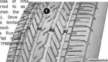
TireTread
NOTE:
TPMS sensor must be replaced after driving the on a flat tire condition.
It is not recommended driving a vehicle loaded at full capacity or to tow a trailer while a tire is in the Run Flat mode page 127.
These indicators are molded into the bottom of Kitrap dismounted tires in a cool, dry place with tread grooves. They will appear as bands when exposure to light as possible. Protect tires from tread depth becomes 1/16 of an inch (1.6 mm with When grease, and gasoline. the tread is worn to the tread wear indicators, the tire should be replaced page 215. ReplacementTires
LifeOfTire
The service life of a tire is dependent upon tors including, but not limited to:
- Driving style.
- Tire pressure - Improper cold tire inflation p can cause uneven wear patterns to develop the tire tread. These abnormal wear patterns reduce tread life, resulting in the need for replacement.
- Distance driven.
- Performance tires, tires with a speed rating higher, and Summer tires typically have a tread life. Rotation of these tires per the scheduled maintenance is highly recommended
ReplacementTires
The tires on your new vehicle provide a balance characteristics. They should be inspected regularly varying and correct cold tire inflation pressures. The manufacturer strongly recommends using tires equivalent to the originals in size, quality and performance when replacement is needed page 214. The Load issues include and Speed Symbol for your tire will be for across the original equipment tire sidewall.
See the Tire Sizing Chart example found in the Safety Information section of this manual for motion relating to the Load Index and Speed Sy a tire page 208.
It is recommended to replace the two front tires
reared tires as a pair. Replacing just one tire car
affect your vehicle's handling. If you ever replace
wheel, make sure that the wheel's specifications
those of the original wheels.
It is recommended you contact an authorized tire.
dealer or original equipment dealer with any question you may have on tire specifications or capability. To use equivalent replacement tires may adversely affect the safety, handling, and ride of your vehicle resulting
| as little contact WARNING! |
| Do not use a tire, wheel size, load rating, or spe rating other than that specified for your vehicle. Some combinations of unapproved tires and where any may change suspension dimensions and for performance characteristics, resulting in changes to steering, handling, and braking of your vehicle. a- This can cause unpredictable handling and stress ance to steering and suspension components. You could lose control and have a collision resulting in seri- boundusonjury or death. Use only the tire and wheel sizes with load ratings approved for your vehicle. Timever use a tire with a smaller load index or ca e byor-other than what was originally equipped on burof vehicle. Using a tire with a smaller load inde could result in tire overloading and failure. You could lose control and have a collision. se raily to equip your vehicle with tires having adequate speed capability can result in sudden mate failure and loss of vehicle control. |
WARNING!
Tires and the spare tire should be replaced years, regardless of the remaining tread. Fail follow this warning can result in sudden tire. You could lose control and have a collision in serious injury or death.
dealer or original equipment dealer with any quest after six you may have on tire specifications or capability. to use equivalent replacement tires may adversely failure. affect the safety, handling, and ride of your veh resulting
| stions Failure | CAUTION! |
| Replacing original tires with tires of a differ day result in false speedometer and odomet readings. | |
NOTE:
Wheel valve stem must be replaced as well when installing new tires due to wear and tear in existing tires.
TIRE TYPES
AllSeasonTires—IfEquipped
All season tires provide traction for all seasons Summer, Autumn, and Winter). Traction levels may be different all season tires. All season tire be identified by the M+S, M&S, M/S or MS d on the tire sidewall. Use all season tires only four; failure to do so may adversely affect the and handling of your vehicle.
SummerOrThreeSeasonTires—IfEquipped
Summer tires provide traction in both wet and additions, and are not intended to be driven in ice. If your vehicle is equipped with Summer tires aware these tires are not designed for Winter driving conditions. Install Winter tires on your vehicle when ambient temperatures are less than 40^ or if roads are covered with ice or snow. For information, contact an authorized dealer.
Summer tires do not contain the all season de or mountain/snowflake symbol on the tire sidewall. Summer tires only in sets of four; failure to d adversely affect the safety and handling of your
SnowTires

Some areas of the country require the snow tires during the Winter. Snow t be identified by a mountain/snowflake
tires can select tires equivalent in size and type of equipment tires. Use snow tires only in a failure to do so may adversely affect the safety handling of your vehicle.
Snow tires generally have lower speed ratings what was originally equipped with your vehicle should not be operated at sustained speeds (75 mph (120 km/h). For speeds above 75 (120 km/h) refer to original equipment or an dye cooler for recommended safe operating speeds, and cold tire inflation pressures. While studded tires improve performance on ice and cold traction capability on wet or dry surfaces, a lower than that of non-studded tires. Some s/heft studded tires; therefore, local laws should check before using these tire types.
SPARE TIRES - IF EQUIPPED
NOTE: may
Ferrich vehicles equipped with Tire Service Kit ins spare tire page 172.
SpareTireMatchingOriginalEquipped TireAndWheel—IfEquipped
Your vehicle may be equipped with a spare tire and wheel equivalent in look and function to the original equipment tire and wheel found on the front or rear axle of your vehicle. This spare tire may be used in tire of four tire rotation for your vehicle. If your vehicle has this option, refer to an authorized tire dealer for the recommended tire rotation pattern.
^a CompactSpareTire—IfEquipped
The compact spare is for temporary emergency use only. You can identify if your vehicle is equipped with a randomized compact spare by looking at the spare tire description on the Tire And Loading Information Placard located on the driver's side door opening or on the sidewall of tire. Compact spare tire descriptions begin with the let may be "or "S" preceding the size designation. Example: 1245/80D18 103M.
be T, S = Temporary Spare Tire
Since this tire has limited tread life, the original equipment tire should be repaired (or replaced) and reinstalled on your vehicle at the first opportunity.
Do not install a wheel cover or attempt to mount a ventiohai ^a tire on the compact spare wheel, since the wheel is designed specifically for the compact spare tire. Do not install more than one compact spare tire and wheel on the vehicle at any given time.
WARNING!
Do not use Summer tires in snow/ice conditions could lose vehicle control, resulting in severe inj death. Driving too fast for conditions also create possibility of loss of vehicle control.
You Because of the reduced ground clearance, do not take the your vehicle through an automatic car wash with a compact or limited use temporary spare installed. Damage to the vehicle may result.
For restrictions when towing with a spare tire designated for temporary emergency usage 96.
WARNING!
Compact and collapsible spares are for temporary emergency use only. With these spares, do not more than 50 mph (80 km/h). Temporary use have limited tread life. When the tread is worn, tread wear indicators, the temporary use spare needs to be replaced. Be sure to follow the which apply to your spare. Failure to do so a result in spare tire failure and loss of vehicle
WARNING!
Compact and collapsible spares are for temporary emergency use only. With these spares, do not spares than 50 mph (80 km/h). Temporary use have limited tread life. When the tread is worn, tread wear indicators, the temporary use spare yards, to be replaced. Be sure to follow the which apply to your spare. Failure to do so could in spare tire failure and loss of vehicle
WARNING!
Limited use spares are for emergency use only. Installation of this limited use spare tire affects vehicle spanning. With this tire, do not drive more than the speedthisted on the limited use spare wheel. Keep inflated to the cold tire inflation pressures listed on young fire And Loading Information Placard located on the driver's side B-pillar or the rear edge of the drone beside door. Replace (or repair) the original equipment tire at the first opportunity and reinstall it on your vehicle. Failure to do so could result in loss of vehicle control.
CollapsibleSpareTire—IfEquipped
The collapsible spare is for temporary emergency Thus full size spare is for temporary emerg only. You can identify if your vehicle is equipped with the area may look like the originally equip collapsible spare by looking at the spare tire description rear axle of your vehicle, but it on the Tire And Loading Information Placard located may have limited tread life. When the driver's side door opening or on the sidewalk the thread wear indicators, the temporary tire. spare tire needs to be replaced. Since it
Collapsible spare tire description example: 165/80-17 101P.
Since this tire has limited tread life, the original ment tire should be repaired (or replaced) and stalled on your vehicle at the first opportunity.
Inflate collapsible tire only after the wheel is pr installed to the vehicle. Inflate the collapsible tire the electric air pump before lowering the vehicle.
Do not install a wheel cover or attempt to preventional tire on the collapsible spare wheel, single wheel is designed specifically for the collapsible gear tire.
FullSizeSpare—IfEquipped
These full size spare is for temporary emergency this with the a may look like the originally equipped resorption rear axle of your vehicle, but it is rated may have limited tread life. When the tread of the thread wear indicators, the temporary use spare tire needs to be replaced. Since it is as your original equipment tire, replace (or repair) original equipment tire and reinstall on the vehicle the first opportunity.
use only.
WHEEL AND WHEEL TRIM CARE
tread All is wheels and wheel trim, especially aluminum and use full size plated wheels, should be cleaned regularly. s not size the same (neutral Ph) soap and water to maintain the repair. The and to prevent corrosion. Wash wheels with the vehicle steam soap solution recommended for the body of the vehicle and remember to always wash when the surfaces are not hot to the touch.
LimitedUseSpare—IfEquipped
The limited use spare tire is for temporary property. Use only. This tire is identified by a label using limited use spare wheel. This label contains limitations for this spare. This tire may look original equipped tire on the front or rear vehicle, but it is not. Installation of this life spare tire affects vehicle handling. Since it
Your wheels are susceptible to deterioration caused by emergency, sodium chloride, magnesium chloride, calcium location, chloride, the, and other road chemicals used in driving control dust on dirt roads. Use a solpike like sponge and mild soap to wipe away promptly. Do not use your fresh chemicals or a stiff brush. They can damage limited these wheel's protective coating that helps keep them
same as your original equipment tire, replace (or repair)
the original equipment tire and reinstall on the vehicle at the first opportunity.
CAUTION!
Avoid products or automatic car washes that acidic solutions or strong alkaline additives or brushes. Many aftermarket wheel cleaners and matic car washes may damage the wheel's finish. Such damage is not covered by the Vehicle Limited Warranty. Only car wash soap, Mopar® Wheel Cleaner or equivalent is recommended.
CAUTION!
use Do not use scouring pads, steel wool, a brist harmetal polishes or oven cleaner. These products aut damage the wheel's protective finish. Such dam protective covered by the New Vehicle Limited Warrar New Only car wash soap, Mopar® Wheel Cleaner or equivalent is recommended.
DarkVaporChrome, BlackSatinChrome, or LowGloss ClearCoatWheels
| e brush,mayCAUTION! |
| ge isIf your vehicle is equipped with these specialty wheels, DO NOT USE wheel cleaners, abrasives, or polishing compounds. They will permanently damage this finish and such damage is not covered by the New Vehicle Limited Warranty. HAND WASH ONLYUSING MILD SOAP AND WATER WITH A SOFT CLOTH.Used on a regular basis; this is all that is required to maintain this finish. |
NOTE:
When cleaning extremely dirty wheels including excess, you intend parking or storing your vehicle to give the extended period after cleaning the wheels with a brake dust, care must be taken in the selection of a cleaner, drive your vehicle and apply the brakes to tire and wheel cleaning chemicals and equipment to prevent damage to the wheels. Mopar® Wheel Treatment or Mopar® Chrome Cleaner or their equivalent is recommended or select a non-abrasive, non-acidic cleaner for aluminum or chrome wheels. This activity will remove the red rust on the vehicle and prevent vehicle vibration when braking.
SNOW TRACTION DEVICES
Use of traction devices require sufficient tire-to-body clearance. Due to limited clearance, the following snow traction devices are recommended. Follow these recommendations to guard against damage:
- Snow traction device must be of proper size for the tire, as recommended by the snow traction device manufacturer.
- No other tire sizes are recommended for use with the snow traction device.
- Please follow the table for the recommended tire size, axle and snow traction device:
| FWDTrimLevel | AxleTire/WheelSize | SnowTractionDevice(MaximumProjectionBeyondTireProfileOrEquivalent) | |
| LXSXT | Front 235/65R17 9 | mm Cable/Chain |
WARNING!
Using tires of different size and type (M+S, between front and rear axles can cause unphandling. You could lose control and have a
CAUTION!
To avoid damage to your vehicle or tires, following precautions:
- Because of restricted traction device cleara between tires and other suspension compc it is important that only traction devices condition are used. Broken devices can c ous damage. Stop the vehicle immediately occurs that could indicate device breakage Remove the damaged parts of the device further use.
• Install device as tightly as possible and retighten after driving about 12 mile (0.8 Autosock traction devices do not require retightening. - Do not exceed 30 mph (48 km/h).
- Drive cautiously and avoid severe turns a bumps, especially with a loaded vehicle.
- Do not drive for a prolonged period on pavement.
- Observe the traction device manufacturer's instructions on the method of installation, ing speed, and conditions for use. Always suggested operating speed of the device turer's if it is less than 30 mph (48 l
- Do not use traction devices on a compact spare tire.
TIRE ROTATION RECOMMENDATIONS
(Snow) predictable tires on the front and rear of your vehicle operate
collision different loads and perform different steering, ing, and braking functions. For these reasons, the wear at unequal rates.
These effects can be reduced by timely rotation. The benefits of rotation are especially worthwhile, observation of tread designs such as those on all type tires. Rotation will increase tread life, help once tain mud, snow and wet traction levels, and comments to a smooth, quiet ride. In the reasons for any rapid or unusual wear show
ause corrected prior to rotation being performed if noise page 184.
The suggested rotation method is the "forward before shown in the following diagram. This rotation does not apply to some directional tires that then be reversed. km).
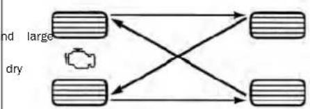
flowchart
graph TD
    A["Rectangle with a small object"] --> B["Rectangle"]
    C["Rectangle with a small object"] --> D["Rectangle"]
    E["Rectangle with a small object"] --> F["Rectangle"]
    G["Rectangle with a small object"] --> H["Rectangle"]
TireRotation(ForwardCross)
DEPARTMENTOFTRANSPORTATION UNIFORMTIREQUALITYGRADES
driv- ey the following tire grading categories were established by the National High- way tires Traffic Safety Administration. The with specific grade rating assigned by the tires again manufacturer in each category is tribute shown on the sidewall of the tires o your vehicle. do be
All passenger vehicle tires must conform to Federal safety requirements in addition to these grades.
TREADWEAR
The Treadwear grade is a comparative rating, based on the wear rate of the tire when tested under controlled conditions on a specified government course. For example, a tire graded 150 would wear one and one-half times as well on the government course as a tire graded 100. The relative performance of tires depends upon the actual conditions of their use, however, and may depart signifi-
cantly from the norm due to variation TEMPERATURE GRADES
in driving habits, service practices, and
differences in road characteristics climate.
TRACTION GRADES
The Traction grades, from highest lowest, are AA, A, B, and C. T grades represent the tire's ability to
stop on wet pavement, as measured stained high temperature can cause under controlled conditions on specthe material of the tire to degenerate fied government test surfaces of and reduce tire life, and excessive asphalt and concrete. A tire markerature can lead to sudden tire failmay have poor traction performanceure. The grade C corresponds to
WARNING!
The traction grade assigned to tire is based on straight-ahead ing traction tests, and does not include acceleration, cornering, hydroplaning, or peak traction characteristics.
and The Temperature grades are A (th highest), B, and C, representing the tire's resistance to the generation heat and its ability to dissipate when tested under controlled condi tions on a specified indoor labora test wheel.
Sustained high temperature can ca
the material of the tire to degenerate
and reduce tire life, and excessive
perature can lead to sudden tire
Figure. The grade C corresponds to of performance, which all passenge
vehicle tires must meet under the eral Motor Vehicle Safety Standard
- Grades B and A represent
brak-levels of performance on the labo
tory test wheel, than the minimum required by law.
WARNING!
The temperature grade for this | tire is established for a tire that is properly inflated and not overloaded. Excessive speed, underinflation, or excessive loading, either separately or in combination, can cause heat buildup and possible tire failure.
STORINGTHEVEHICLE
you are storing your vehicle for more than three eks, we recommend that you take the following step minimize the drain on your vehicle's battery:
Disconnect the negative cable from battery.
No. time you store your vehicle or keep it out of
gher (i.e., vacation) for two weeks or more, run the
air conditioning system at idle for about five minute
In the fresh air and high blower setting. This will
ensure adequate system lubrication to minimize the possibility of compressor damage when the system
possibility of compressor damage when the system is started again
BODYWORK
BODY AND UNDERBODY MAINTENANCE
PROTECTION FROM ATMOSPHERIC AGENTS
CleaningHeadlights
Vehicle body care requirements vary according to
graphic locations and usage. Chemicals that make
roads passable in snow and ice and those that
sprayed on trees and road surfaces during other
sons are highly corrosive to the metal in your Outside parking, which expense your vehicle to a
outside parking, which exposes your vehicle to a contaminants and surfaces on which the vehicle
contaminants, road surfaces on which the vehicle
operated, extreme hot or cold weather and other extreme conditions will have on extreme effect
extreme conditions will have an adverse effect of metal trim and underbody protection.
metal trim, and underbody protection.
The following maintenance recommendations will
enable you to obtain maximum benefit from the
sion resistance built into your vehicle.
Your vehicle is equipped with plastic headlights lights that are lighter and less susceptible to breakage than glass headlights.
^t are Plastic is not as scratch resistant as glass and
r sea-different lens cleaning procedures must be followed.
to minimize the possibility of scratching the le
reducing light output, avoid wiping with a dry
remove road dirt, wash with a mild soap solu
lowed by rinsing.
Do not use abrasive cleaning components, solve
steel wool or other aggressive material to clear
lenses como-
PRESERVING THE BODYWORK
CAUTION!
- Do not use abrasive or strong cleaning materials such as steel wool or scouring powder that will scratch metal and painted surfaces.
and fog Use of power washers exceeding 1,200 psi (8,274 kPa) can result in damage or removal of paint and decals.
SpecialCare
- It is important that the drain holes in the lower the edges of the doors, rocker panels, and trunk be clear and open.
- If you detect any stone chips or scratches in the paint, touch them up immediately. The cost of such repairs is considered the responsibility of the owner.
- If your vehicle is damaged due to a collision or : lar cause that destroys the paint and protective
Coating, have your vehicle repaired as soon as completely. The cost of such repairs is considered the responsibility of the owner.
acqu- you carry special cargo such as chemical sleepers, de-icer salt, etc., be sure that such materials are well packaged and sealed.
ar@f a lot of driving is done on gravel roads, consic to mprop- or stone shields behind each wheel.
- scratch Use Mopar® Touch Up Paint on scratches as soon as possible. An authorized dealer has touch up
fing paint to match the color of your vehicle. paint
WhatCausesCorrosion?
Corrosion is the result of deterioration or removal paint and protective coatings from your vehicle.
The most common causes are:
- Road salt, dirt and moisture accumulation.
• Stone and gravel impact.
• Insects, tree sap and tar. - Salt in the air near seacoast localities.
• Atmospheric fallout/industrial pollutants.
Washing
- Wash your vehicle regularly. Always wash your vehicle in the shade using Mopar® Car Wash mild car wash soap, and rinse the panels co with water.
- If insects, tar, or other similar deposits have mulated on your vehicle, use Mopar® Super Bug and Tar Remover to remove.
- Use a high quality cleaner wax, such as Mo Cleaner Wax to remove road film, stains and tect your paint finish. Use precautions to not the paint.
- Avoid using abrasive compounds and power but that may diminish the gloss or thin out the finish.
INTERIORS
SEATS AND FABRIC PARTS
Use Mopar® Total Clean to clean fabric upholstery carpeting.
WARNING!
Do not use volatile solvents for cleaning purposes. Many are potentially flammable, and if used in areas they may cause respiratory harm.
PLASTIC AND COATED PARTS
Use Mopar® Total Clean to clean vinyl uph
liquid. Please do not use polishes, oils, cleaning fluids,
solvents, detergents, or ammonia-based cleaners to
'clean your leather upholstery.
and
CAUTION!
- Direct contact of air fresheners, insect repuntan lotions, or hand sanitizers to the painted, or decorated surfaces of the inte cause permanent damage. Wipe away is. Immediately.
- Damage caused by these type of products be covered by your New Vehicle Limited
NOTE:
If equipped with light colored leather, it tends to show every foreign material, dirt, and fabric dye transfer more soic, than darker colors. The leather is designed for each cleaning, and the manufacturer recommends Mopar® total care leather cleaner applied on a cloth to clean the leather seats as needed.
s may not Warranty.
CAUTION!
Do not use alcohol and alcohol-based and/or ketone-based cleaning products to clean leather seats, as damage to the seat may result.
SeatBeltMaintenance
Do not bleach, dye or clean the belts with ch vents or abrasive cleaners. This will weaken the
If the belts need cleaning, use a mild soap lukewarm water. Do not remove the belts from vehicle to wash them. Dry with a soft cloth.
Sun damage can also weaken the fabric. Repla belts if they appear frayed or worn or if the not work properly.
WARNING!
A frayed or torn seat belt could rip apart in and leave you with no protection. Inspect the belt system periodically, checking for cuts, frays, loose parts. Damaged parts must be replaced i diately. Do not disassemble or modify the seat system. If your vehicle is involved in a collision you have questions regarding seat belt or retra conditions, take your vehicle to an authorized F dealer or authorized FCA Certified Collision Care gram facility for inspection.
CleaningPlasticInstrumentCluster Lenses
tion lenses in front of the instruments in this tholded in clear plastic. When cleaning the len must be taken to avoid scratching the plastic.
e the clean with a wet soft cloth. A mild soap so buckles do used, but do not use high alcohol content or cleaners. If soap is used, wipe clean with a cloth. Dry with a soft cloth.
LEATHER SURFACES
a collision Mopar® Total Clean is specifically recommended seat leather upholstery.
Your leather upholstery can be best preserved. I felt cleaning with a damp soft cloth. Small pa dirt can act as an abrasive and damage the upholstery and should be removed promptly with damp cloth. Stubborn soils can be removed each soft cloth and Mopar® Total Clean. Care s taken to avoid soaking your leather upholstery
GLASS SURFACES
All glass surfaces should be cleaned on a regular bas tion may be with Mopar® Glass Cleaner, or any commercial abrasive
Household-type glass cleaner. Never use an abrasive clean lamp. Use caution when cleaning the inside red window equipped with electric defrosters or windows equipped with radio antennas. Do not use scrapers or other sharp instruments that may scratch the elements.
When cleaning the rearview mirror, spray cleaner on the towel or cloth that you are using. Do not spray clear wire-tau-on the mirror.
TECHNICALSPECIFICATIONS
VEHICLEIDENTIFICATIONNUMBER(VIN)
The VIN is on the left front corner of the insight warrant will still function. However, the effort required to panel and is visible from outside of the vehicle broke the vehicle will be much greater. the windshield.
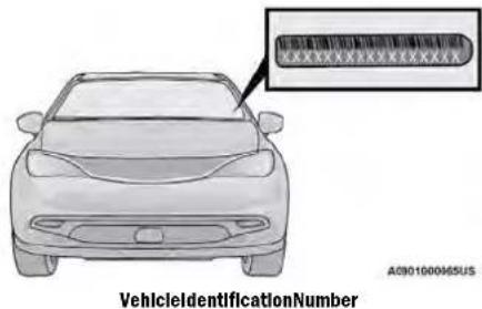
NOTE:
It is illegal to remove or alter the VIN.
BRAKESYSTEM
In the event power assist is lost for any reason (i.e., repeated brake applications with the engine off) the
brakes will still function. However, the effort required to brake the vehicle will be much greater.
WHEELANDTIRETORQUE SPECIFICATIONS
Proper lug nut/bolt torque is very important to ensure that the wheel is properly mounted to the vehicle. Any time a wheel has been removed and reinstalled on the vehicle, the lug nuts/bolts should be torqued using a properly calibrated torque wrench using a six-sided (hex) deep wall socket. Tighten
TORQUE SPECIFICATIONS
| LugNut/Bolt Torque | **LugNut/Bolt Size | LugNut/Bolt SocketSize |
| 100 ft-lb(135 N·m) | M12 x 1.5 | 19 mm |
**Use only authorized dealer recommended lug nuts/
bolts and clean or remove any dirt or oil before
ke, SVS-
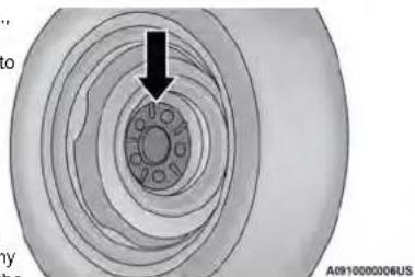
natural_image
Cross-sectional diagram of a mechanical bearing or housing with concentric layers and a central hub, no visible text or symbols.WheelMountingSurface
Tighten the lug nuts/bolts in a star pattern until each nut/bolt has been tightened twice. Ensure that the socket is fully engaged on the lug nut/bolt (do not insert it halfway).
fightening e normal Inspect the wheel mounting surface prior to mounting how- the tire and remove any corrosion or loose particles. effective
Your vehicle is equipped with dual hydraulic brake systems. If either of the two hydraulic systems lose normal capability, the remaining system will still function. Insect the wheel mounting surface prior to mounting ever, there will be some loss of overall braking effectiveness. You may notice increased pedal travel during application, greater pedal force required to slow or stop, and potential activation of the Brake Warning Light.
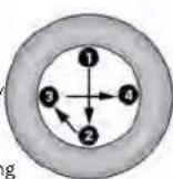
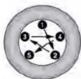
A0910000005US
TorquePatterns
After 25 miles (40 km) check the lug nut/bolt be sure that all the lug nuts/bolts are properly tightened.
WARNING!
To avoid the risk of forcing the vehicle off not tighten the lug nuts/bolts fully until the has been lowered. Failure to follow this war result in personal injury.
FUELREQUIREMENTS
While operating on gasoline with the required oct number, hearing a light knocking sound from the engine is not a cause for concern. However, if engine is heard making a heavy knocking sound, dealer immediately. Use of gasoline with a lower recommended octane number can cause engine fa and may void or not be covered by the New ited Warranty.
Poor quality gasoline can cause problems such as starting, stalling, and hesitations. If you experience these symptoms, try another brand of gasoline be considering service for the vehicle.
3.6L ENGINE
Do not use E-85 flex fuel or ethanol blends 15% in this engine.

This engine is designed to meet all sions regulations and provide optimum economy and performance when using quality unleaded regular gasoline havin
posted octane number of 87 as specified by
2orquethod. The use of higher octane premium is not required, as it will not provide any b regular gasoline in these engines.
REFORMULATED GASOLINE
Many areas of the country require the use of a jack, gas gasoline referred to as "reformulated hole". Reformulated gasoline contains oxygenates and specifically blended to reduce vehicle emissions improve air quality.
The use of reformulated gasoline is recommended. Undesirable lean conditions
Properly blended reformulated gasoline will provide ● OBD II Malfunction Indicator Light on
improved performance and durability of engine system components.
GASOLINE/OXYGENATE BLENDS
the Some fuel suppliers blend unleaded gasoline see a genates such as ethanol.
niluru
| Vehicle Lim-CAUTION! |
| DO NOT use E-85, gasoline containing meth gasoline containing more than 15% ethanol Use of these blends may result in starting ability problems, damage critical fuel system nents, cause emissions to exceed the applied standard, and/or cause the Malfunction Indica Light to illuminate. Please observe pump lab ethery should clearly communicate if a fuel d greater than 15% ethanol (E-15). |
eProblems that result from using gasoline containing ghore than 15% ethanol (E-15) or gasoline containing amethanol are not the responsibility of the manufacturer
andR+May void or not be covered under New Vehicle Limited Warranty.
gasoline NOT USE E-85 IN NON-FLEX FUEL OVER
Non-Flex Fuel Vehicles (FFV) are compatible with gasoline containing up to 15% ethanol (E-15). Use of gasoline with higher ethanol content may void the New Vehicle Limited Warranty.
aref a Non-FFV vehicle is inadvertently fueled with s and 5 fuel, the engine will have some or all of these symptoms:
with CNG AND LP FUEL SYSTEM MODIFICATIONS
Modifications that allow the engine to run on Com-pressed Natural Gas (CNG) or Liquid Propane (LP) may not result in damage to the engine, emissions, and fuel system components. Problems that result from running and NDRivor LP are not the responsibility of the manufacturer and may void or not be covered under the NE Vehicle Limited Warranty.
METHYLCYCLOPENTADIENYL MANGANESE TRICARBONYL (MMT) IN GASOLINE
usage of Top Tier Detergent gasoline is recommend:
Visit www.toptiergas.com, at the link below, for a intentional tampering with the emissions control system
TOP TIER Detergent Gasoline retailers. can result in civil penalties being assessed against you
Indiscriminate use of fuel system cleaning agents
should be avoided. Many of these materials intended
for gum and varnish removal may contain active sol
vents or similar ingredients. These can harm fuel sys-
ance tem gasket and diaphragm materials.
number
\*FUEL SYSTEM CAUTIONS
MMT is a manganese-containing metallic additive is blended into some gasolines to increase octane. Gasoline blended with MMT provides no performance advantage beyond gasoline of the same octane without MMT. Gasoline blended with MMT reduces spark plug life and reduces emissions system performance in some vehicles. The manufacturer recommends that gasoline without MMT be used in y vehicle. The MMT content of gasoline may not be cated on the gasoline pump; therefore, you should your gasoline retailer whether the gasoline contains MMT. MMT is prohibited in Federal and California, cumulated gasoline.
MATERIALS ADDED TO FUEL
Besides using unleaded gasoline with the proper octane rating, gasolines that contain detergents, c sion and stability additives are recommended. Use gasolines that have these additives will help imp fuel economy, reduce emissions, and maintain vel performance.

Designated TOP TIER Detergent Gasoline contains a higher level of detergents to ther aide in minimizing engine and fuel osits. When available, the usage of TOP gasoline is recommended. Visit ergas.com for a list of TOP TIER Deterg retailers.
Designated TOP TIER Detergent Gasoline contains higher level of detergents to further aide in min engine and fuel system deposits. When available,
| ourCAUTION! |
| see indi |
| follow these guidelines to maintain your vehicle's performance: |
| • There use of leaded gasoline is prohibited by Federal law. Using leaded gasoline can impair engine performance and damage the emissions control system. |
| • An out-of-tune engine or certain fuel or ignition malfunctions can cause the catalytic converter to overheat. If you notice a pungent burning odor or some light smoke, your engine may be out of tune or malfunctioning and may require immediate service. Contact an authorized dealer for service assistance. |
| • The use of fuel additives, which are now being sold as octane enhancers, is not recommended. Most of these products contain high concentrations of methanol. Fuel system damage or vehicle performance problems resulting from the use of such fuels or additives is not the responsibility of the manufacturer and may void or not be covered under the New Vehicle Limited Warranty. |
FLUIDCAPACITIES
| USMetric | ||
| Fuel(Approximate) | ||
| 3.6L Engine 19 gal 71 L | ||
| EngineOilWithFilter | ||
| 3.6L Engine 5 qt 4.7 L | ||
| CoolingSystem* | ||
| 3.6L Engine 15 qt 14.2 L | ||
| * Includes heater and coolant reservoir filled to MAX level. | ||
ENGINEFLUIDSANDLUBRICANTS
| ComponentFluid,Lubricant,orGenuinePart | |
| Engine Coolant | We recommend using Mopar® Antifreeze/Coolant 10 Year/150,000 Mile (240,000 km) Formula OAT (Organic Additive Technology) or equivalent meeting the requirements of the manufacturer Material Standard MS.90032. |
| Engine Oil - 3.6L Engine | We recommend using Mopar® SAE 0W-20 Full Synthetic Engine Oil which meets the requirements of the manufacturer Material Standard MS-6395. Equivalent full synthetic SAE 0W-20 engine oil can be used but must have the □page standard trademark |
| Fuel Selection - 3.6L Engine | 87 Octane (R+M)/2 Method, 0-15% ethanol (Do not use E-85). |
CAUTION!
- Mixing of engine coolant (antifreeze) other than specified Organic Additive Technology (OAT) engine coolant (antifreeze), may result in engine damage and may decrease corrosion protection. Organic Additive Technology (OAT) engine coolant is different and should not be mixed with Hybrid Organic Additive Technology (HOAT) engine coolant (antifreeze) or any “globally compatible” coolant (antifreeze). If a non-OAT engine coolant (antifreeze) is introduced into the cooling system in an emergency, the cooling system will need to be drained, flushed, and refilled with fresh OAT coolant (conforming to MS.90032), by an authorized dealer as soon as possible.
- Do not use water alone or alcohol-based engine coolant (antifreeze) products. Do not use additional rust inhibitors or antirust products, as they may not be compatible with the radiator engine coolant and may plug the radiator.
- This vehicle has not been designed for use with propylene glycol-based engine coolant (antifreeze). Use of propylene glycol-based engine coolant (antifreeze) is not recommended.
CHASSISFLUIDSANDLUBRICANTS
| ComponentFluid,Lubricant,or GenuinePart | |
| Automatic Transmission | Use only Mopar® ZF 8 & 9 Speed ATF Automatic Transmission Fluid, or equivalent.Failure to use the correct fluid may affect the function or performance of your transmission. |
| Brake Master Cylinder We recommend using Mopar® DOT 3 Brake Fluid, SAE J1703 should be used. | |
CUSTOMERASSISTANCE
SUGGESTIONSFOROBTAININGSERVICE FORYOURVEHICLE
PREPARE FOR THE APPOINTMENT
All work to be performed may not be covered warranty. Discuss additional charges with the se manager. Keep a maintenance log of your veh vice history. This can often provide a clue to problem.
PREPARE A LIST
Make a written list of your vehicle's problems specific work you want done. If you've had an or work done that is not on your maintenance the service advisor know.
BE REASONABLE WITH REQUESTS ^to
If you list a number of items and you must have your vehicle by the end of the day, discuss the situation should include the following information: the service advisor and list the items in order of priority. At many authorized dealers, you may obtain a rental vehicle (additional charges may apply). If you need owner's telephone number (home, mobile, and rental, it is advisable to make these arrangements office) when you call for an appointment. Authorized dealer name
IFYOUNEEDASSISTANCE
FCA US LLC and its authorized dealers are ested in your satisfaction. We want you to our products and services.
Warranty service must be done by an authorized dealer.
We strongly recommend that you take the vehicle Who is Covered
authorized dealer. They know your vehicle the best and you are covered by Roadside Assistance services if you are most concerned that you get prompt and high quality of a purchaser for use of the vehicle. Roadside Assi y service. FCA US LLC's authorized dealers have the services last for five years or 60,000 miles on facilities, factory-trained technicians, special tools, and doometer, whichever occurs first, calculated from the the latest information to ensure the vehicle is fixed date of the Basic Limited Warranty, as set forth rectly and in a timely manner. your Warranty Information book.
This is why you should always talk to an authorized service services provided through Cross Country Motor Club, Inc., dealer's service manager first. If for some reason you see the Edge Drive, Medford, MA 02155, except In AK, CA, HI, accident and not satisfied, talk to the general manager of WY, where services are provided by Cross Country Motor Club, Inc. or owner of the authorized dealer. They want to know California, Inc., 275 East Hillcrest Drive, Suite 165, Thousand Oaks you need assistance. If an authorized dealer is unable
to resolve the concern, you may contact FCA What to Do Customer Assistance center. If your
ROADSIDE ASSISTANCE
Available 24 hours, 7 days a week.
Call 1-800-521-2779 or visit chrysler.rsahelp.com(USA)
Call 1-800-363-4869 or visit fca.roadsideaid.com
d(Canada)
cWhdisCovered
If your vehicle requires jump start assistance, out of fuel delivery, tire service, lockout service or towing as a result of a mechanical breakdown, dial toll-free: USA: 1-800-521-2779/Canada: 1-800-363-4869. Provide your name, Vehicle Identification Number (VIN) required for covered services, license plate number, and your location, including the telephone number from which you are calling. Briefly describe the nature of the problem and answer a few simple questions. You will given the name of the service provider and an estimated time of arrival. If you feel you are in an un situation, please let us know. With your consent, we contact local police or safety authorities.
IfUnabletoContactRoadsideAssistance
BatteryJumpAssistance
If you are unable to contact Roadside Assistance No time is a good time for a depleted battery. With unable to provide a valid Vehicle Identification Roadside Assistance, you do not have to worry about (VIN), and you obtain towing services on your being you stranded. We will dispatch a service provider to may submit your original receipts from the licensed service you with a battery jump anytime, day or Santeht.Fe C.P. 05109
ing or service facility, for services rendered within LockoutService 30 days of the occurrence. Be sure to include your VIN.
odometer mileage at the time of service, and current mailing address. We will process the claim based on a phone call away. This service is limited to provide vehicle and service eligibility. If eligible, we will just a phone call away. This service is limited to provide
burse you for the reasonable amount actually paid access to the vehicle's seating based on the usual and customary charges for over the cost of replacement keys.
vice in the area where they were provided. FCATowBngService
determination relating to reimbursement is final. spondence should be mailed to:
FCA US LLC Customer Assistance
P.O. Box 9145
Medford, MA 02155
Attention Claims Department
FCA US LLC reserves the right to modify the discontinue the Roadside Assistance Program at time. The Roadside Assistance program is subject restrictions and conditions of use, which are
mined solely by FCA US LLC.
FlatTireService
If you are Inconvenienced by a flat tire, we will dispatch a service provider to use your vehicle's temporarily spare tire (if equipped) as recommended in your Owneps. Box 1621
Manual. This is not a permanent flat tire repair. Windsor, Ontario N9A 4H6 OutofGas/FuelDelivery Phone: (800) 465-2001 English / (800)
Drivers cannot always count on a gas station being 387-9983 French
nearby, especially when travelling away from home. We
will dispatch a service provider to deliver a small amount of fuel (maximum two gallons) to get you to a nearby station. This service is limited to two occur-
rences in a 12-month period.
MEXICO
With CustomerRelationsOffice about
'Outside Mexico City: +(52)55 50817568
to provid- Puerto RICO AND US VIRGIN
ISLANDS
FCACaribbeanLLCCustomerService
BBox a 191857
San Juan 00919-1857
to the Phone: (800) 247-9753
CUSTOMER ASSISTANCE FOR THE HEARING OR SPEECH IMPAIRED (TDD/TTY)
To assist customers who have hearing difficulties, FCA US LLC has installed special TDD (Telecommunication Devices for the Deaf) equipment at its customer centre. Any hearing or speech impaired customer, who has access to a TDD or a conventional teletypewriter (TTY) in the United States, can communicate with FCA US LLC by dialing 1-800-380-2479.
Canadian residents with hearing difficulties that require assistance can use the special needs relay service offered by Bell Canada. For TTY teletypewriter dial 711 and for Voice callers, dial 1-800-855 connect with a Bell Relay Service operator.
SERVICE CONTRACT
You may have purchased a service contract for vehicle to help protect you from the high cost pected repairs after FCA US LLC's New Vehicle Warranty expires. The Mopar® Vehicle Protection are the ONLY vehicle extended protection plans rized, endorsed and backed by FCA US LLC to additional protection beyond your vehicle's warrant you purchased a Mopar® Vehicle Protection Plan will receive Plan Provisions and an Owner Ident Card in the mail within three weeks of the very date. If you have any questions about the contract, call FCA US LLC's Service Contract Na
Customer Hotline at 1-800-521-9922.
For Canadian residents, you may have purchased
tional coverage with an extended service contract.
Canada Inc. stands fully behind its service contracts. Further information.
Be sure that the one you buy is a genuine Canada French.
service contract. We are not responsible for other information.
panies' contracts. If you purchased a contract of
than a genuine FCA Canada Inc. service contract and
you have a problem, you will have to contact the admin-
istrator of that contract for resolution. If you have any
questions about the service contract, call the FCA's Ser-
vice Contract National Customer Hotline at (800) 465-
2001 English / (800) 387-9983 French).
FCA US LLC is not responsible for any service contract
you may have purchased from another manufacturer. If
you require service after the FCA US LLC New Vehicle
Limited Warranty expires, please refer to the contract
documents, and contact the person listed in those
documents.
We appreciate that you have made a major in
when you purchased the vehicle. An authorized
Has also made a major investment in facilities.
of unex and training to assure that you are absolutely
Limited the ownership experience.
plans
WARRANTYINFORMATION
See, the Warranty Information for the terms and
sions of FCA US LLC warranties applicable to
vehicle and market. Refer to www.mopar.com/om
further information.
dna Canada:
See the Warranty Information for the terms and
signs of FCA Canada Inc. warranties applicable
vehicle and market. Refer to owners.mopar.ca/en/
further information.
Canada French, refer to owners.monar.ca/fr/ for furth
inf60mation.
her ItsethisORcodetoaccessyourdigital
and
the experience: admin-
MOPAR®PARTS dealer
tools
Mobark® original equipment parts & accessories and delighted factory filled fluids are available from an authorized dealer. They are recommended for your vehicle to keep it operating at its best and maintain its original condition.
REPORTING SAFETY DEFECTS
IN THE 50 UNITED STATES AND WASHINGTON, D.C.
If you believe that your vehicle has a defect that could cause a crash or cause injury or death, you should immediately inform the National Highway Traffic Safety Administration (NHTSA) in addition to notifying FCA U LLC.
If NHTSA receives similar complaints, it may open an investigation, and if it finds that a safety defect exists in a group of vehicles, it may order a rec and remedy campaign. However, NHTSA cannot become involved in individual problems between you, an authorized dealer or FCA US LLC.
To contact NHTSA, you may call
Vehicle Safety Hotline toll free at
1-888-327-4236 (TTY:
http://www.safercar.gov; or write to:
Administrator, NHTSA, 1200 New
Jersey Avenue, SE., West Building,
Washington, D.C. 205
obtain other information about mo
vehicle safety from
http://www.safercar.gov.
IN CANADA
If you believe that your vehicle safety defect, you should contact
Customer Service Department imm
ately. Canadian customers who w
report a safety defect to the C
government should contact Transpo
Canada, Motor Vehicle Defect Inv
gations and Recalls at
1-800-333-0510 or go to
wwwapps.tc.gc.ca/Saf-Sec-Sur/7/
PCDB-BDPP.
PUBLICATIONORDERFORMS
To order the following manuals, you may use website or the phone numbers listed below.
ServiceManuals
These comprehensive Service Manuals provide a
plete working knowledge of the vehicle, system,
components and is written in straightforward law with illustrations, diagrams, and charts.
with illustrations, diagrams, and charts. DiagnosticProcedureManuals
Diagnostic Procedure Manuals are filled with diag
charts and detailed illustrations. These manuals
it easy to find and fix problems on computer-
vehicle systems and features. They show exactly
find and correct problems, using step-by-step tro
shooting and drivability procedures, proven diagne
tests and a complete list of all tools and ec
To order a digital copy of your Service or Di
the are manuals, visit:
www.techauthority.com (US and Canada).
Owner's Manuals
These Owner's Manuals have been prepared with
assistance of service and engineering specialists
acquaint you with specific FCA vehicles.
Std- access your Owner's Information online, visit
www.mopar.com/om (US) or www.owners.mopar.ca/en
(Canada).
Or visit:
www.techauthority.com to order physical copies of
Owner's Manuals (US).
Owner's Manuals, Radio Manuals and Warranty
mation Books can be ordered through Archway
• 1-800-387-1143(Canada)
ChangeOfOwnershipOrAddress
either you have purchased this vehicle used or have changed your address, please provide the following information and mail to:
ECAUSLLC
and/orBox 21-8008
Auburn Hills, MI 48321-8004
Make sure to include the following:
• Date of Sale (mm/dd/yy)
- Vehicle Identification Number (17 Character ID
lake located on top left of the instrument panel)
How to Exact Odometer Reading
ble-First and Last Name
tic Phone Number
pment. • Street Address, City, State and Zip Code
gnostic Pro- Email Address
*Applies to US residents only.
GENERALINFORMATION
The following regulatory statement applies to all Radio Frequency (RF) devices equipped in this vehicle:
,This device complies with Part 15 of the FCC Rules
with Innovation, Science and Economic Development
Canada license-exempt RSS standard(s). Operation is
subject to the following two conditions:
- This device may not cause harmful interference, and
2r- This device must accept any interference r
t: including interference that may cause undesi
operation.
Changes or modifications not expressly approved by the party responsible for compliance could void the user's authority to operate the equipment.
INDEX
| A | Air Pressure | B | |
| About Your Brakes. | 2 2 3 Tires | 2 Back Up Camera. . . . . . . . . . . . . . . . . . . . . . . . . . . . . . . . . . . . . . . . . . . . . . . . . . . . . . . . . . . . . . . . . . . . . . . . . . . . . . . . . . . . . . . . . . . . . . . . . . . . . | 1 8 9 |
| Adding Engine Coolant (Antifreeze) | Alarm5 | Base Instrument Clusted. . . . . . . . . . . . . . . . . . . . . . . . . . . . . . . . . . . . . . . . . . . . . . . . . . . . . . . . . . . . . . . . . . . . . . . . . . . . . . . . . . . . . . . . . . . . . . . . . . . | 5 8 |
| Additives, Fuel | Arm, The22System | 1 Battery. . . . . . . . . . . . . . . . . . . . . . . . . . . . . . . . . . . . . . . . . . . . . . . . . . . . . . . . . . . . . . . . . . . . . . . . . . . . . . . . . . . . . . . . . . . . . . . . . . . | |
| Adjust | Disarm The System | 1 7 Charging System Light. . . . . . . . . . . . . . . . . . . . . . . . . . . . . . . . . . . . . . . . . . . . . . . . . . . . . . . . . . . . . . . . . . . . . . . . . . . . . . . . . . . . . . . . . . . . . . . . . . . | |
| Down | 3 2 Security Alarm | 6 7 Jump Starting. . . . . . . . . . . . . . . . . . . . . . . . . . . . . . . . . . . . . . . . . . . . . . . . . . . . . . . . . . . . . . . . . . . . . . . . . . . . . . . . . . . . . . | 1 7 7 |
| Forward | Alterations/Modifications | Keyless Key Fob Replacement. . . . . . . . . . . . . . . . . . . . . . . . . . . . . . . . . . . . . . . . . . . . . . . . . . . . . . . . . . . . . . . . . . . . . . . . . . . . . . . . | 1 2 |
| Rearward | V3e2hicle | Battery Saver Feature. . . . . . . . . . . . . . . . . . . . . . . . . . . . . . . . . . . . . . . . . . . . . . . . . . . . . . . . . . . . . . . . . . . . . . . . | 3 9 |
| Up | 3 2 Antifreeze (Engine Coolant) | 1 9 5 Belts,2 Seat. . . . . . . . . . . . . . . . . . . . . . . . . . . . . . . . . . . . . . . . . . . . . . . . . . . | 1 6 0 |
| Air Bag | 1 3 Disposal | 1 9 6 Blind Spot Monitoring. . . . . . . . . . . . . . . . . . . . . . . . . . . . . . . . . . . . . . . . . . . . . . . . | 1 9 1 |
| Air Bag Operation | 1 Anti-Lock Brake System (ABS) | 1 Body Mechanism Lubrication. . . . . . . . . . . . . . . . . . . . . . . . . . . . . . . . . . . . . . . | 1 9 1 |
| Air Bag Warning Light | 1 3 Anti-Lock Warning Light. | 6 B-Pillar Location. . . . . . . . . . . . . . . . . . . . . . . . . . . . . . . | 2 1 0 |
| Driver Knee Air Bag | 1 Aasis, Hill Start. | 1 2 Brake Assist System. . . . . . . . . . . . . . . . . . . . . . . . | 1 1 8 |
| Enhanced Accident Response | 1 4 6 Audi Jack | 5 0 Brake Control System, Electronic. . . . . . . . . . . . . | 118 |
| Event Data Recorder (EDR) | 1 Audio Systems (Radio) | 1 0 Brake Fluid. . . . . . . . . . . . . . . | 2 2 7 |
| Front Air Bag | A u.t.o1m4 otic Dimming Mirror | Brake System. 3 6. . . . 1 9 7 , 2 2 3 | |
| If Deployment Occurs | 1 Automatic Headlights | 3 9 Anti-Lock (ABS) | 2 2 3 |
| Knee Impact Bolsters | 1 Automatic Transaxle | 7 8 Fluid Check. . . . 1 9 7 , 2 2 7 | |
| Maintaining Your Air Bag System | Automatic Transmission. | 7 9 Master Cylinder. . . . 1 9 7 | |
| Maintenance | 1 4 6 Adding Fluid | 1 P8 r2 n7g. | 7 6 |
| Redundant Air Bag Warning Light | 1 Fluid And Filter Change | 1 9 Warning Light. . . . 6 5 | |
| Side Air Bags | 1 4 3 Fluid Change | 1 9 Brake/Transmission Interlock. | 79 |
| Transporting Pets | 1 6 0 Fluid Level Check | 1 9 Brightness, Interior Lights. | 4 0 |
| Air Bag Light | 6 5 F1 g8 d1 6 p e | 1 Bulb Replacement. 204, 206 | |
| Air Cleaner, Engine (Engine Air Cleaner Filter). | 1 Special Additives | 1 9 Bulbs, Light. | 1 6 1 , 2 |
| Air Conditioner Maintenance | 1 Agu to Park. | 7 2 | |
| Air Conditioner Refrigerant | 1 8 9 Alugl o Uppower Windows | 5 3 | |
| Air Conditioner System | 1 8 W X Cord | C 5 0 | |
| Air Conditioning Filter | 4 7 Auxiliary Electrical Outlet (Power Outlet) | c 5 1 m er a. | 8 9 |
| Air Conditioning, Operating Tips | 4 Axte Lubrication | 2 2 Camera, Rear. | 8 9 |
| Air Filter | 1 8 8 | Capacities, Fluid. Caps, Filler. Fuel | |
| Oil (Engine) | 1 8 Cooling System | 1 9 B | |
| Radiator (Coolant Pressure) | 1 9 6 Adding Coolant (Antifreeze) | 1 Electric Brake Control System | 1 1 8 |
| Carbon Monoxide Warning | 1 6 Coolant Level | 1 9 6 Anti-Lock Brake System | 1 1 7 |
| Cargo | Cooling Capacity | 2 2 6 Traction Control System | 1 2 1 |
| Vehicle Loading | 5 6 Disposal Of Used Coolant | 1 Electric Parking Brake | 7 6 |
| Cargo Load Floor | 5 6 Drain, Flush, And Refill | 1 Electronic Stability Control (ESC) | 1 1 9 |
| Car Washes | 2 2 1 Inspection | 1 9 5 ,1 Electronic Throttle Control Warning Light. | 6 6 |
| Cellular Phone | 1 1 6 P o i n t s T o R e m b e r | Emergency Braking | 126 |
| Certification Label | 9 0 Pressure Cap | 1 9 Emergency Gas Can Refueling | 1 7 8 |
| Chains, Tire | 2 1 8 Radiator Cap | 1 9 Emergency, In Case Of | |
| Change Oil Indicator | 6 1 Selection Of Coolant (Antifreeze) | 1 9 5 ,Hazard Warning Flasher | 1 6 3 |
| Changing A Flat Tire | 1 Corrision Protection | 2 2 Jacking | 1 6 5 ,1 6 7 |
| Chart, Tire Sizing | 2 OC Raise Control | 8 3 Overheating | 1 7 9 |
| Check Engine Light (Malfunction Indicator Light) | Cruis 4 Light | 6 9 ,7 OT ow i ng | 1 8 |
| Checking Your Vehicle For Safety | Customer Assistance | 2 2 Emission Control System Maintenance | 7 1 |
| Checks, Safety | 1 6 Cybersecurity | 1 0 Engine | 1 8 6 |
| Child Restraint | 1 4 7 | Air Cleaner | 1 8 8 |
| Child Restraints | Block Heater | 7 5 | |
| Booster Seats | 1 4 D | Break-In Recommendations | 7 5 |
| Center Seat LATCH | 1 5 Daytime Running Lights | 3 Checking Oil Level | 1 8 7 |
| Child Seat Installation | 1 5 5 ,Dealer Service | 1 8 8 C om p a r t m e n t | |
| How To Stow An unused ALR Seat Belt | Defrost 5 ,5 Windshield | 1 6 O Compartment Identification | 1 8 6 |
| Infant And Child Restraints | 1 Delar (Intermittent) Wipers | 4 1 Coolant (Antifreeze) | 226 |
| Lower Anchors And Tethers For Children | Diagnostic System, Onboard | 7 0 C o o l i n g | 1 9 4 |
| Older Children And Child Restraints | 1 Dimmer Switch | Exhaust Gas Caution | 1 6 2 |
| Seating Positions | 1 5 0 Headlight | 3 7 Fails To Start | 7 4 |
| Using The Top Tether Anchorage | Dipsticks | Flooded, Starting | 7 4 |
| Clean Air Gasoline | 2 2 Oil (Engine) | 1 8 7 Fuel Requirements | 2 2 4 |
| Cleaning | Disable Vehicle Towing. | 1 8 10 i l | 1 8 8 ,2 2 6 |
| Wheels | 2 1 7 Disposal | Oil Filler Cap | 1 8 6 |
| Climate Control | 4 2 Antifreeze (Engine Coolant) | 1 9 60 I I F l t e r | 1 8 |
| Manual | 4 2 Door Ajar | 6 5 ,6 Oil Selection | 1 8 8 ,2 2 6 |
| R e a r | 4 Door Ajar Light | 6 5 ,6 Oil Synthetic | 1 8 8 |
| Cold Weather Operation | 7 Driver's Seat Back Tilt. | 23, 24 Overheating | 1 7 9 |
| Compact Spare Tire | 2 Drving | Starting | 7 2 |
| Contract, Service | 230 Through Flowing, Rising, Or Shallow Standing | Enhanced Accident Response Feature | 1 4 6 ,1 8 |
| Cooling Pressure Cap (Radiator Cap) | 1 W a t er | Ethanol | 2 2 4 |
| Exhaust Gas Cautions | 1 6 Gasoline | 2 2 4 Heated Seats. | 3 3 |
| Exhaust System | 1 6 2 , 1 Materials Added | 2 2 Heater, Engine Block | 7 5 |
| Exterior Lighting | 3 7 , 2 Methanol | 2 2 4 Hill Start Assist | .120 |
| Exterior Lights. | 3 7 , 1 6 1 , 204. Octobere Rating | 2 2 4 , 2 Holes | |
| Requirements | 2 2 4 Trailer Towing | ||
| Specifications | 2 2 6 Hood Prop | 5 4 | |
| F | Tank Capacity | .226 Hood Release | 5 4 |
| Filters | Fuses | 1 9 8 | |
| Air Cleaner | 1 8 8 | ||
| Air Conditioning | 4 7 , 1 9 0 | I | |
| Engine Oil | 1 8 8 , 6 2 6 | Ign it i on. | 1 3 |
| Engine Oil Disposal | 1 Gas Cap (Fuel Filler Cap) | 8 9 w it ch | 1 3 |
| Flashers | Gasoline, Clean Air | 2 214 n side R e a r v i e w M ir r or | |
| Hazard Warning | 1 6 Gasoline, (Fuel) | 2 2 4 Instrument Cluster | .58, 60 |
| Turn Signals | 3 7 , 7 0 , 1 Gasoline, OR Formulated | 2 2 4 Descriptions | 7 0 |
| Flash-To-Pass | 3 7 , Gear Ranges | 7 9 D is p l ay | 6 0 |
| Flat Tire Changing | 1 6 5 , 2 Glass 2Cbing | 2 2 2 Display Controls | 6 0 |
| Flat Tire Stowage | Gross Axle2 Weight 2Rating | 9 1M en u l tem s | 6 |
| Flooded Engine Starting | 7 Gross Vehicle Weight Rating | Instrument Panel Lens Cleaning | .222 |
| Fluid, Brake | 2 2 G 7 W R | 9 Interior And Instrument Lights | 4 0 |
| Fluid Capacities | .226 | Interior Appearance Care | .222 |
| Fluid Leaks | 1 6 1 | Interior Lights | 4 0 |
| Fluid Level Checks | H | ||
| Brake | 1 9 Hazard | ||
| Engine Oil | 1 8 7 Driving Through Flowing, Rising, Or | J | |
| Fog Lights | 3 7 Shallow Standing Water | 9 Sacking And Tire Changing - If Sipped | 1 6 |
| Fold-Flat Seats | 2 3 Hazard Warning Flashers | 1 6a3k Location | 1 6 6 |
| Fold In Floor (Stow 'n Go) Seating | Headights | 3 7 Jack Operation | 1 6 5 |
| Forward Collision Warning | .125 Cleaning | 2 2 1 Jump Starting | 1 7 7 |
| Freeing A Stuck Vehicle | 1 8 High Beam/Low Beam Select Switch | 3 7 | |
| Front Position Light | Lights On 20 Reminder | 3 7 , 3 9 | |
| Fuel | 2 2 Passing | 3 7 , 3 K9 | |
| Additives | S .225 tch | K .e3y7 F o b | 1 1 |
| Clean Air | T A n 4 Delay | A m7 The System | 1 7 |
| Ethanol | 2 2 Head Restraints | 3 3 Disarm The Alarm | 1 7 |
| Filler Cap (Gas Cap) | Heared Mirrors | 36, 37 Programming Additional Key Fobs | 1 2 |
Key Fob Battery Service (Remote Keyless Entry
| Key Fob Programming (Remote Keyless Entry)....Basing....37,3 Automatic Dimming.... | ||
| Key less Enter 'n GoTM....Reading..19....40 Exterior Folding....37 | ||
| Passive Entry....19 Seat Belt Reminder....67 Heated....36,37 | ||
| Keys....11 Security Alarm....67 Outside....36 | ||
| Service....204 e a r v i e w....36,16: | ||
| Side Marker....V a 0 6 ty....36 | ||
| L | Traction Control....120 Modifications/Alterations | |
| Lane Change And Turn Signals....3 Turn Signals....37,70,16 V e 2 h 6 le....7 | ||
| Lane Change Assist....37,3 Warning Instrument Cluster Descriptions....66, Monitor, Tire Pressure System....127 | ||
| Lap/Shoulder Belts....13 Load Floor, Cargo....5 Mopar Parts....230 | ||
| Latches....16 Loading Vehicle....56,SIRS Control....50 | ||
| Hood....54 Tires....MultiFunction Control Lever....37 | ||
| Lead Free Gasoline....2 Load Shed Battery Saver Mode....64 | ||
| Leaks, Fluid....16 Load Shed Battery Saver On....64 | ||
| Life Of Tires....Load 2 Shed Electrical Load Reduction....N64 | ||
| Liftgate....54 Load Shed Intelligent Battery Sensor....Now4 Vehicle Break-In Period....75 | ||
| Power....Locks | ||
| Light Bulbs....1 Child Protection....17 | ||
| Lights....161 Manual....170 | ||
| Air Bag....65,138,16 Power Door....17 Occupant Restraints....129 | ||
| Battery Saver....3 Low Tire Pressure System....1 Octane Rating, Gasoline (Fuel)...224,22 | ||
| Brake Assist Warning....12 Lubrication, Body....19 Oil Change Indicator....61 | ||
| Brake Warning....65 Lug Nuts....2 Reset....61 | ||
| Bulb Replacement....204,206...Oil, Engine....188,226 | ||
| Cruise....69,70...Capacity....226 | ||
| Daytime Running....37M...Checking....187 | ||
| Dimmer Switch, Headlight....3 Maintenance Free Battery....18 Dipstick....187 | ||
| Engine Temperature Warning....6 Maintenance Schedule....184 Disposal....188 | ||
| Exterior....Malfunction Indicator Light (Check Engine)....68,71...Filter....188,2 | ||
| Headlights....37,3 Manual...Filter Disposal....188 | ||
| High Beam/Low Beam Select....37Park Release....180 Identification Logo....188 | ||
| Instrument Cluster....37 Service....2 Materials Added To....188 | ||
| Intensity Control....40 Map/Reading Lights....40 Pressure Warning Light....66 | ||
| Interior....Marked Lights, Side....20 Recommendation....188,226 | ||
| Lights On Reminder....37,Media Hub....Synthetic....188 | ||
| Malfunction Indicator (Check Engine)....6 Methanol....224 Viscosity....226 | ||
| Park....6 Mirrors....Oil 3 Filter, Change....188 | ||
| Oil Filter, Selection | 1 | R 8 | S | |
| Oil Life Re | 6 | 1 Radial Ply Tires | 2 Safety Checks Inside Vehicle. | 1 6 0 |
| Oil Pressure Light | 6 | Radiator Cap (Coolant Pressure Cap) | Safety 6 Checks Outside Vehicle | 1 6 1 |
| Onboard Diagnostic System | Radio Operation | 1 Safety Defects, Reporting | 230 | |
| Operating Precautions | 7 | Radio Remote Controls | 1 Safety, Exhaust Gas | 1 6 2 |
| Operator Manual | Rear Air Conditioning | 4 Safety Information Tire | ||
| Owner's Manual | 2 | 3 R1e a r C r o s s P at h | Sa f1e 2 Tips | 1 6 |
| Outside Rearview Mirrors | Rear ParkSense System | 8 Schedule, Maintenance | 1 8 4 | |
| Overheating, Engine | 1 | Rear Seat Reminder | 1 Screen Setup. | 6 3 |
| R e a r V i e w | Seat 3 Belt Reminder | 6 7 | ||
| Reclining Front Seats | 2 Seat Belts | 1 3 0, 1 6 0 | ||
| P | Recreational Towing | 9 7 Adjustable Shoulder Belt | 1 3 3 | |
| Paint Care | 2 | 2 Reformulated Gasoline | 2 2 4 Adjustable Upper Shoulder Anchorage | 1 3 3 |
| Parking Brake | 7 | Refrigerant | 1 9 0 Adjustable Upper Shoulder Belt Anchorage | 133 |
| ParkSense System, Rear | 8 Release, Hood | 5 4 Automatic Locking Retractor (ALR) | 1 3 5 | |
| Passive Entry | 1 | Reminder, Lights On | 3 7 Child Restraints | 1 4 7 |
| P e t s | Reminder, Seat Belt | 1 3 Energy Management Feature | 1 3 5 | |
| Placard, Tire And Loading Information | Remote Control | Extender | 1 3 5 | |
| Power | Starting System | 1 4 Front Seat | 130, 131, 132 | |
| Brakes | 2 | 2 3 Remote Keyless Entry | Inspection | 1 6 0 |
| M ir r or s | 3 7 m T he A l ar m | Lap/Shoulder Belt Operation | 1 3 2 | |
| Outlet (Auxiliary Electrical Outlet) | 5 1 Disarm The Alarm | 1 7 Lap/Shoulder Belts | 1 3 1 | |
| Seats | 3 | 2 Programming Additional Key Fobs | 1 2 Lap/Shoulder Belt Untwisting | 1 3 2 |
| Steering | 8 | 1 Remote Sound System (Radio) Control | 1 Operating Instructions | 1 3 2 |
| Power Seats | Remote Starting | Pregnant Women | 1 3 5 | |
| D o w n | 3 2 Exit Remote Start Mode | 1 5 Pretensioners | 1 3 5 | |
| F o r w a r d | 3 U connect Customer Programmable Features | 16 Rear Seat | 1 3 1 | |
| R e a r w a r d | B o c nnect Settings | 1 6 Reminder | 1 3 0 | |
| U p | 3 | 2 Remote Starting System | 1 4 Seat Belt Extender | 1 3 5 |
| Power Sliding Door | Replacement Bulbs | 2 0 4 Seat Belt Pretensioner | 1 3 5 | |
| On / Off Switch | 21, 55 | Replacement Tires | 2 1 5 Untwisting Procedure | 1 3 2 |
| Pregnant Women And Seat Belts | Reporting Safety Defects | 2 3 Seat Belts Maintenance | 222 | |
| Preparation For Jacking | 1 Restraints, Child | 1 4 Seats. | 23, 32, 33 | |
| Pretensioners | Restraints, Head | 3 3 Adjustment | 23, 24, 25, 32 | |
| Seat Belts | 1 | 3 Rotation, Tires. | 2 1 9 Heated | 3 3 |
Power 32 Rear Folding 21
| Reclining | Steeding Wheel Audio Controls | 1 Safety | 207,2 |
| Seatback Release | 24 Steering Wheel Mounted Sound System Controls | $16 z es | 208 |
| Stow 'n Go (Fold in Floor) | Storage | 47 Snow Tires | 2 |
| Tilting | 2 Stove 4n, Qo5 (Fold In Floor) Seats | Space9 Tires | 166,216,2 |
| Security Alarm | 67 Stuck, Freeing | 180 Spinning | 2 |
| Arm The System | 1 Sunglasses Storage | 48 Trailer Towing | |
| Disarm The System | 1 Supplemental Restraint System - Air Bag | Trba8 Wear Indicators | 214 |
| Selection Of Coolant (Antifreeze) | 2 Swap Control, Trailer | 12 Wheel Nut Torque | .223 |
| Sentry Key (Immobilizer) | 1 Symbol Glossary | 7 Tire Safety Information | |
| Service Assistance | .228 Synthetic Engine Oil | 178 e Service Kit | |
| Service Contract | .230 System, Remote Starting | 1 Tire Service Kit - If Eupbed | 172 |
| Service Manuals | 231 | Tire Stowage | 1 |
| Shifting | Tongue Weight/Trailer Weight | 95 | |
| Automatic Transmission | 79 | To Open Hood | 54 |
| Shoulder Belts | 13 Telescoping Steering Column | 2 tw ing | 91 |
| Side View Mirror Adjustment | 3 Tie Steering Column | 23 Disabled Vehicle | 181 |
| Signals, Turn | 37,70,1 Time Delay 6 | Guide | 93 |
| Snow Chains (Tire Chains) | 21 Headlight | 37 Recreational | 97 |
| Snow Tires | Tire And Goading Information Placard | 2 Weight | 93 |
| Spare Tire Changing | 1 Pre Markings | Towing 28hird A Motorhome | 97 |
| Spare Tires | 166,2161,r2e1s7 | 161,21 Traction 1.6.,21.9 | 98 |
| Spare Tire Stowage | 172 Aging (Life Of Tires) | 2 Traction Control | 121 |
| Specifications | Air Pressure | 21 Trailer Sway Control (TSC) | |
| Oil | .226 Chains | 218 Trailer Towing | |
| Speed Control | Changing | 92 | |
| Cancel | 84 Compact Spare | 216 Minimum Requirements | 95 |
| Resume | 84 General Information | 213,216ps | 97 |
| Starting | 14,72 High Speed | 214 Trailer And Tongue Weight | 95 |
| Button | 13 Inflation Pressure | 213 Wiring | 96 |
| Cold Weather | 75 Jacking | 165,1Terrailer Towing Guide | |
| Engine Falls To Start | 74 Life Of Tires | Tr a215r Weight | |
| Remote | 1 Load Capacity | 2 Transaxle | |
| Starting And Operating | 72 Pressure Monitoring System (TPMS) .62,68,127 Automatic | ||
| Starting Procedures | 72 Quality Grading | 219 Operation | 78 |
| Steering | 81 Radial | 214 Transmission | 79 |
| Tilt Column | Replacement | .79,19 | |
| Wheel, Heated | 23 Rotation | 219 Maintenance | 197 |
| Wheel, Tilt | 23 |
Transporting Pets 1 6W0ind Buffeting 53
Tread Wear Indicators 2 Window Fogging 47
Turn Signals 37,70W,i2n0d6ow s 52
Power 52
Windshield Defroster 160
U Windshield Washers 4 1, 1 8 7
Uconnect Fluid 187
Uconnect Settings 1 6Windshield Wiper Blades 1 9 1
Uconnect 4C/4C Nav With 8.4-Inch Display....Wipers1 Blade Replacement....191
Uconnect Settings Wipers, Intermittent. 41
Customer Programmable Features ..... 1 6 Wrecker Towing ..... 1 8 1
Passive Entry Programming 19
Uniform Tire Quality Grades 2 1 9
Unleaded Gasoline 2 2 4
Untwisting Procedure, Seat Belt 132
U S B 50
V
Vanity Mirrors....36
Vehicle Identification Number (VIN) .....223
Vehicle Loading 90,210
Vehicle Maintenance 188
Vehicle Modifications/Alterations 7
Voice Command 35
W
Warning Lights And Messages. 6 5
Warning Lights (Instrument Cluster Descriptions) . .67
Warranty Information 230
Washers, Windshield 187
Washing Vehicle. 2 2 1
Water
Driving Through 99
Wheel And Wheel Tire Care 2 1 7
Wheel And Wheel Tire Trim. 2 1 7
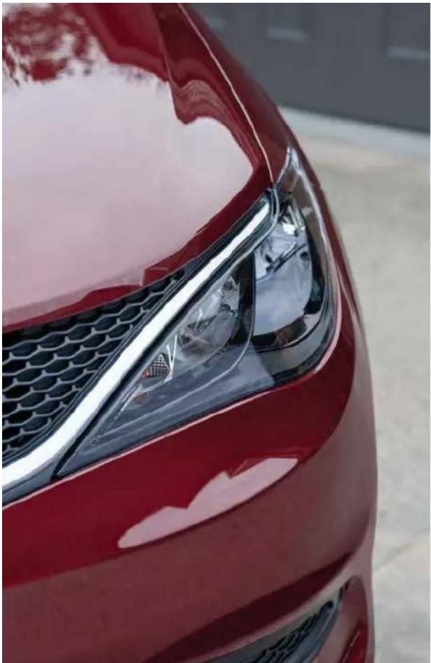
natural_image
Close-up of a red car's front wheel and grille (no visible text or symbols)The driver's primary responsibility is the safe operation of the vehicle. Driving while distracted can result in loss of vehicle control, resulting in an accident and personal injury. FCA US LLC strongly recommends that the driver use extreme caution when using any device or feature that may take their attention off the road. Use of any electrical devices, such as cellular telephones, computers, portable radios, vehicle navigation or other devices by the driver while the vehicle is moving is dangerous and could lead to a serious accident. Texting while driving is also dangerous and should never be done while the vehicle is moving. If you find yourself unable to devote your full attention to vehicle operation, pull off the road to a safe location and stop your vehicle. Some states or provinces prohibit the use of cellular telephones or texting while driving. It is always the driver's responsibility to comply with all local laws.
This Owner's Manual has been prepared to help you get acquainted with your new Chrysler brand vehicle and to provide a convenient reference source for common questions.
Not all features shown in this manual may apply to your vehicle. For additional information, visit mopar.com/om (USA), owners.mopar.ca (Canada) or your local Chrysler dealer.
U.S. Residents: If you are the first registered retail owner of your vehicle, you may obtain a complimentary printed copy of the Warranty Booklet by calling 1-800-247-9753 or by contacting your dealer. Replacement kits can be purchased by visiting www.techauthority.com.
Canadian Residents: If you are the first registered retail owner of your vehicle, you may obtain a complimentary printed copy of the Warranty Booklet or purchase a replacement kit by calling 1-800-387-1143 or by contacting your dealer.
DRIVING AND ALCOHOL
Drunk driving is one of the most frequent causes of accidents. Your driving ability can be seriously impaired with blood alcohol levels far below the legal minimum. If you are drinking, don't drive. Ride with a designated non-drinking driver, call a cab, a rideshare, a friend, or use public transportation.
WARNING
Driving after drinking can lead to an accident. Your perceptions are less sharp, your reflexes are slower and your judgment is impaired when you have been drinking. Never drink and then drive.
Whether it's providing information about specific product features, taking a tour through your vehicle's heritage, knowing what steps to take following an accident or scheduling your next appointment, we know you'll find the app an important extension of your Chrysler brand vehicle. Simply download the app, select your make and model and enjoy the ride. To get this app, go directly to the App Store ^® or Google Play ^® Store and enter the search keyword "Chrysler" (U.S. residents only).
SCAN TO DOWNLOAD COMPLETE OWNER'S MANUAL, RADIO AND WARRANTY MANUALS
U.S.
mopar.com/om
CANADA
owners.mopar.ca
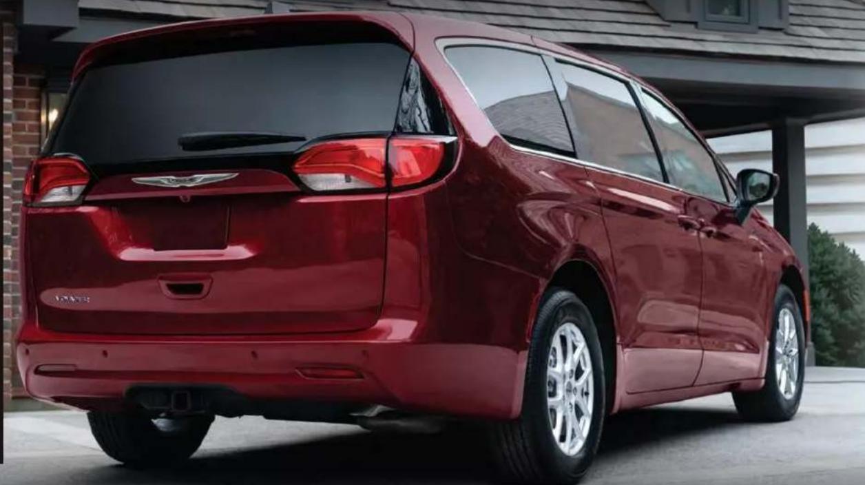
natural_image
Red minivan parked under a covered roof, no visible text or symbols on the vehicle or background.
- TABLEOFCONTENTS
- INTRODUCTION
- GETTINGTOKNOWYOUR INSTRUMENTPANEL
- STARTING ANDOPERATING
- TECHNICALSPECIFICATIONS
- CUSTOMERASSISTANCE
- SUGGESTIONSFOROBTAININGSERVICEFOR
- SYMBOLGLOSSARY
- NOTE:
- KEY FOB
- VehiclesEquippedWithKeylessEnter'nGo™—PassiveEntry
- KeyLeftVehicleFeature
- ReplacingTheBatteryInTheKeyFob
- WARNING!
- over ProgrammingAndRequesting any of the AdditionalKeyFobs
- DIS NOTE:
- SENTRYKEY
- OFF
- ACC
- ON/RUN
- START
- con
- CAUTION!
- REMOTESTART—IFEQUIPPED
- T0 Position EXIT REMOTE START MODE
- HOW TO USE REMOTE START
- REMOTE START FRONT DEFROST ACTIVATION — IF EQUIPPED
- REMOTE START ABORT MESSAGE
- REMOTE START COMFORT SYSTEMS — IF EQUIPPED
- VEHICLESECURITYSYSTEM— IFEQUIPPED
- AutomaticTemperatureControl(ATC)—IfEquipped
- REMOTE START WINDSHIELD WIPER DE-ICER ACTIVATION — d 2 mal EQUIPPED
- TO ARM THE SYSTEM
- SECURITY SYSTEM MANUAL
- OVERRIDE
- DOORS
- MANUAL DOOR LOCKS
- TO DISARM THE SYSTEM
- REARMING OF THE SYSTEM
- POWER DOOR LOCKS — IF EQUIPPED
- KEYLESS ENTER 'N GO™ — PASSIVE ENTRY
- ToUnlockFromTheDriverOrPassengerSide:
- FrequencyOperatedButtonIntegratedKey
- (FOBIK-Safe)
- ToLockTheVehicle'sDoorsAndLiftgate
- ToUnlock/EnterTheLiftgate
- AUTOMATIC UNLOCK DOORS ON EXHUST — IF EQUIPPED
- .MANUAL SLIDING SIDE DOOR
- CHILD PROTECTION DOOR SYSTEM — REAR DOORS
- ToDisengageTheChildProtectionDoorLock
- STEERINGWHEEL
- TILT/TELESCOPING STEERING COLUMN
- HEATED STEERING WHEEL — IF EQUIPPED
- NOTES
- SEATS
- MANUAL ADJUSTMENT (FRONT SEATS) — IF EQUIPPED
- ManualSeatHeightAdjustment—IfEquipped
- ManualFrontSeatReclineAdjustment
- ManualFrontAdjuster
- MANUAL ADJUSTMENT (REAR
- SEAT
- ManualForward/RearwardAdjustment —QuadSeats(IfEquipped)
- ManualRecline—Stow'nGoSeats
- adjusted Fold-FlatStow'nGoSeats
- EasyEntry
- EasyEntry—WithTheSeatFoldedFlat
- ManuallyFoldingThirdRowSeats—IfEquipped
- ExitForThirdRowPassengers—Stow'nGoSeatsOnly
- ToUnfoldThirdRowSeats
- Stow'nGoSeating
- SECONDROWSTOW'NGO
- TOUNSTOWSECONDROWSEATS
- POWER ADJUSTMENT (FRONT SEATS) — IF EQUIPPED
- AdjustingTheSeatForwardOr Rearward
- AdjustingTheSeatUpUpDown
- the seat terious TiltingTheSeatUpUpDown
- RecliningTheSeatback
- HEATED SEATS
- FrontHeatedSeats—IfEquipped
- HEAD ® RESTRAINTS
- HeadRestraints—FrontSeats
- HeadRestraints—SecondRowStow'n GoSeats
- HeadRestraints—ThirdRow
- BASIC VOICE COMMANDS
- UconnectVoiceRecognition—IfEquipped
- INTRODUCING VOICE RECOGNITION
- GET STARTED
- MIRRORS
- PILLUMINATED VANITY MIRRORS — a).IF EQUIPPED
- INSIDE REARVIEW MIRROR
- ManualMirror
- ADDITIONAL INFORMATION
- OUTSIDE MIRRORS
- CONVERSATION MIRROR
- OUTSIDE MIRRORS FOLDING FEATURE
- HEATED MIRRORS — IF EQUIPPED
- LIGHTINGOPERATION
- POWER MIRRORS — IF EQUIPI
- MULTIFUNCTION LEVER
- HEADLIGHT SWITCH
- DAYTIME RUNNING LIGHTS (DRLS) — IF EQUIPPED
- FLASH-TO-PASS
- AUTOMATIC HEADLIGHTS — IF EQUIPPED
- INTERIORLIGHTS
- INTERIOR COURTESY LIGHTS
- RearCourtesy/ReadingLights—IfEquipped
- DimmerControls
- WINDSHIELDWIPER&WASHERS
- most off light-
- NOTEin
- IntermittentWipers
- WindshieldWashers
- Mist
- RAIN SENSING WIPERS — IF EQUIPPED
- operly REAR WIPER AND WASHER
- CLIMATECONTROLS the trans-
- MAXA/CButton
- A/CButton
- RecirculationButton
- FrontDefrostButton
- RearDefrostButton
- FrontTemperatureControl
- BlowerControl
- Bi-LevelMode
- FloorMode
- SYNCButton
- ModeControl
- MixMode
- Mode ClimateControlOFFButton
- PanelMode
- ControllingTheRearClimateControls FromTheFrontMTCDisplay/
- Touchscreen
- Tochangetherearsystemsettings:
- REARCLIMATECONTROLBUTTON
- REARLOCKBUTTON
- FRONTCLIMATEBUTTON
- REARTEMPERATURECONTROL
- REARPASSENGERCLIMATECONTROLOFF
- RearManualTemperatureControl(MTC)
- REARBLOWERCONTROL
- REARMODECONTROL
- the NOTE:
- CLIMATE VOICE COMMANDS
- will " shut Set driver temperature to 70 degrees"
- OPERATING TIPS
- SummerOperation
- WinterOperation
- Vacation/Storage
- WindowFogging
- OutsideAirIntake
- CabinAirFilter
- Stop/StartSystem—IfEquipped
- OperatingTipsChart
- INTERIORSTORAGEANDEQUIPMENT
- STORAGE
- GloveCompartment
- FrontDoorStorage
- OverheadSunglassStorage
- InstrumentPanelDrawer
- FrontSeatbackStorage—IfEquipped
- SecondRowFloorStorageBins
- STORAGEBINSAFETYWARNING
- 2
- SEATSTORAGEBINCOVEREMERGENCY RELEASELEVER
- USB/AUX CONTROL
- POWER OUTLETS
- 3rdRowUSBChargingPort—IfEquipped12VoltFrontPowerDilEst
- Windows
- POWER WINDOWS
- SlidingSideDoorPowerWindowControl—IfEquipped
- Auto-UpFeatureWithAnti-PinchProtection
- RESET AUTO UP
- WIND _stop. BUFFETING
- HOOD
- OPENING
- TO pas- CLOSE THE HOOD
- LIFTGATE
- TO UNLOCK/OPEN THE LIFTGATE
- POWER LIFTGATE — IF EQUIPPED
- NOTE!
- vtbCloseTheLiftgate
- CARGO AREA FEATURES
- may cargoAreaStorage
- GETTINGTOKNOWYOURINSTRUMENTPANEL
- BASEINSTRUMENTCLUSTER
- BASE INSTRUMENT CLUSTER DESCRIPTIONS
- PREMIUMINSTRUMENTCLUSTER
- PREMIUM INSTRUMENT CLUSTER DESCRIPTIONS
- INSTRUMENT CLUSTER DISPLAY LDER LOCATION AND CONTROLS
- INSTRUMENTCLUSTERDISPLAY
- OIL LIFE RESET
- UsethisQRcodetoaccessyourdigital experience.
- INSTRUMENT CLUSTER DISPLAY MENU ITEMS
- Speedometer
- VehicleInfo
- TirePressure
- CoolantTemp
- TransmissionTemp
- OilTemp
- OilPressure
- OilLife
- BatteryVoltage
- EngineHours—IfEquipped
- FuelEconomy
- at all
- Triplinfo
- ge Dwiller
- Stop/Start-IfEquipped
- Audio
- Messages
- ScreenSetup
- BASEINSTRUMENTCLUSTERDISPLAY SCREENSETUOPTIONS
- Odometer
- BATTERY SAVER ON/BATTERY SAVER MODE MESSAGE — ELECTRICAL LOAD REDUCTION ACTIONS — IF EQUIPPED
- Whattodowhenanelectricalloadreductionaction messageispresent("BatterySaverOn" or "Battery SaverMode")
- WARNINGLIGHTSANDMESSAGES
- AirBagWarningLight
- BatteryChargeWarningLight
- BrakeWarningLight
- ElectricPowerSteering(EPS)Fault WarningLight
- ElectronicThrottleControl(ETC)Warning Light
- EngineCoolantTemperatureWarning Light
- sHoodOpenWarningLight
- LiftgateOpenWarningLight
- OilTemperatureWarningLight
- OilPressureWarningLight
- SeatBeltReminderWarningLight
- TransmissionTemperatureWarning Light
- VehicleSecurityWarningLight—IfEquipped
- YELLOW WARNING LIGHTS
- Anti-LockBrakeSystem(ABS)Warning Light
- ElectronicStabilityControl(ESC)Active WarningLight—IfEquipped
- ElectronicStabilityControl(ESC)OFF WarningLight—IfEquipped
- EngineCheck/MalfunctionIndicator WarningLight(MIL)
- FuelLevelSensorFailureWarningLight
- LowFuelWarningLight
- LowWasherFluidWarningLight—IfEquipped
- ServiceAutomaticEmergencyBraking (AEB)orPedestrianEmergencyBraking (PEB)WarningLight—IfEquipped
- ServiceStop/StartSystemWarning Light—IfEquipped
- TirePressureMonitoringSystem(TPMS) WarningLight
- Stop/StartActiveIndicatorLight—IfEquipped
- TurnSignalIndicatorLights
- WHITE INDICATOR LIGHTS
- CruiseControlReadyIndicatorLight
- SetSpeedDisplayIndicatorLight
- BLUE INDICATOR LIGHTS
- HighBeamIndicatorLight
- ONBOARDDIAGNOSTICSYSTEM—OBDII
- ONBOARD DIAGNOSTIC SYSTEM (OBD II) CYBERSECURITY
- EMISSIONSINSPECTIONAND MAINTENANCEPROGRAMS
- NORMAL STARTING
- Autobark
- AutoParkInStop/StartAutostopMode
- ToTurnOnTheEngineUsingENGINESTART/STOP Button
- If the drivershifts into PARK while moving, the vehicle may Park.
- EXTENDED PARK STARTING
- IF ENGINE FAILS TO START
- AFTER STARTING — WARMING THE ENGINE
- TO TURN OFF THE ENGINE ENGINE START/STOP BUTTON
- ENGINEBLOCKHEATER—IFEQUIPPED
- - ENGINEBREAK-INRECOMMENDATIONS
- PARKINGBRAKE
- ELECTRIC PARK BRAKE (EPB)
- AutoParkBrake
- SafeHold
- BrakeServiceMode
- AUTOMATICTRANSMISSION
- Light ON
- r NEUTRAL if eed. If your
- ake, shift ignition IGNITION PARK INTERLOCK
- GEAR RANGES
- aRARK(P)
- LOW(L)
- DRIVE(D)
- TransmissionLimpHomeMode
- REVERSE(R)
- NEUTRAL(N)
- ACTIVENOISECANCELLATION
- POWERSTEERING
- NOTE: four
- TorqueConverterClutch
- AUTOSTOP MODE
- POSSIBLE REASONS THE ENGINE DOES NOT AUTOSTOP
- TO THE START THE ENGINE WHILE d in AUTO STOP/START
- ConditionsThatWillCauseTheEngineToStartAutomaticallyWhileInAutoStop/Start:
- TO MANUALLY TURN OFF THE STOP/START SYSTEM
- TO MANUALLY TURN ON THE STOP/START SYSTEM
- SYSTEM MALFUNCTION
- CRUISECONTROLSYSTEMS— IFEQUIPPED
- CRUISE CONTROL
- ToActivate
- ToSetADesiredSpeed
- ToVaryTheSpeedSetting
- U.S.Speed(mph)
- MetricSpeed(km/h)
- ToResumeSpeed
- ToDeactivate
- PARKSENSERARPARKASSIST— IFEQUIPPED
- ToAccelerateForPassing
- USINGCRUISECONTROLONHILLS
- PARKSENSE SENSORS
- PARKSENSE WARNING DISPLAY
- ENABLING AND DISABLING PARKSENSE
- to SERVICE THE PARKSENSE REAR display PARK ASSIST SYSTEM
- CLEANING THE PARKSENSE SYSTEM
- PARKSENSE SYSTEM USAGE PRECAUTIONS
- PARKVIEWREARBACKUPCAMERA
- NOTE
- F position.
- REFUELINGTHEVEHICLE
- "top off"
- VEHICLELOADING
- CERTIFICATION LABEL
- GrossVehicleWeightRating(GVWR)
- Payload
- GrossAxleWeightRating(GAWR)
- TireSize
- RimSize
- InflationPressure
- GVWR CurbWeight
- Loading
- TRAILERTOWING
- that the COMMON TOWING DEFINITIONS
- W Gross Vehicle Weight Rating(GVWR)
- GrossCombinationWeightRating (GCWR)
- TongueWeight(TW)
- TrailerFrontalArea
- GrossTrailerWeight(GTW)
- TrailerSwayControl(TSC)
- Weight-DistributingHitch
- Weight-CarryingHitch
- TRAILER HITCH CLASSIFICATION
- VEHICLE LOADING CHART
- EXAMPLE:
- TRAILER AND TONGUE WEIGHT TOWING REQUIREMENTS
- d promote proper break-in of your new vehicle train components, the following guidelines are recommended.
- equipment
- TowingRequirements—Tires
- TowingRequirements—TrailerBrakes
- TowingRequirements—TrailerLights AndWiring
- TOWING TIPS
- CruiseControl—IfEquipped
- RECREATIONALTOWING(BEHINDMOTORHOME)
- RecreationalTowing
- DRIVING TIPS
- Acceleration
- follow-
- Traction
- DRIVING ON SLIPPERY
- SURFACES
- DRIVING THROUGH WATER
- Flowing/RisingWater
- ShallowStandingWater
- MULTIMEDIA
- UCONNECTSYSTEMS
- to UCONNECT SETTINGS
- CYBERSECURITY
- CUSTOMER PROGRAMMABLE FEATURES
- ForTheUconnect5With7-inchDisplayandTheUconnect5/5NAVWith10.1-inchDisplay
- MyProfile
- Display
- Safety&DrivingAssistance
- Clock&Date
- Phone/Bluetooth®
- Voice—IfEquipped
- Navigation—IfEquipped
- Camera
- Mirrors&Wipers
- Lights
- Brakes
- Doors&Locks
- Seats&Comfort
- KeyOffOptions
- Notifications
- SiriusXM®Setup
- SoftwareUpdates
- SystemInformation
- Reset
- STEERINGWHEELAUDIOCONTROLS
- RADIO OPERATION
- MEDIA MODE
- RADIOOPERATIONANDMOBILEPHONES
- REGULATORY AND SAFETY INFORMATION
- SAFETY
- SAFETYFEATURES
- REAR SEAT REMINDER ALERT tires or (RSRA)
- BrakeAssistSystem(BAS)
- BrakeSystemWarningLight
- DynamicSteeringTorque(DST)
- s ElectronicBrakeForceDistribution or the (EBD)
- ElectronicRollMitigation(ERM)
- ElectronicStabilityControl(ESC)
- ESCOperatingModes
- ESCON
- ve PartialOff es. or
- HillStartAssist(HSA)
- to hold DisablingAndEnablingHSA
- TractionControlSystem(TCS)
- th TrailerSwayControl(TSC)
- AUXILIARYDRIVINGSYSTEMS
- BLIND SPOT MONITORING (BSM) — IF EQUIPPED
- ReadyAlertBraking(RAB)
- RainBrakeSupport(RBS)
- EnteringFromTheSide
- EnteringFromTheRear
- OvertakingTraffic
- RearCrossPath(RCP)
- BlindSpotAlertLights/Chime
- BlindSpotModes
- BlindSpotAlertOff
- FORWARD COLLISION WARNING (FCW) WITH MITIGATION — IF EQUIPPED
- TurningFCWOnOrOff
- event such
- FCWBrakingStatusAndSensitivity
- only page 100.
- FCWLimitedWarning allows
- ServiceFCWWarning
- TurningPEBOnOrOff
- TIRE PRESSURE MONITORING SYSTEM (TPMS)
- PremiumSystem
- SERVICETPMSWARNING
- VehiclesWithCompactSpare—IfEquipped
- TIREPRESSUREMONITORINGSYSTEMLOW PRESSUREWARNINGS
- TPMSDEACTIVATION—IFEQUIPPED
- beET SEAT BELT SYSTEMS
- tEnhancedSeatBeltUseReminder
- System(BeltAlert)
- DriverAndPassengerBeltAlert—IfEquipped
- dattialadication
- BeltAlertWarningSequence
- ChangeOfStatus
- Lap/ShoulderBelts
- Lap/ShoulderBeltOperating Instructions
- Lap/ShoulderBeltUntwistingProcedure
- AdjustableUpperShoulderBelt Anchorage
- SecondRowCenter(IfEquipped)And ThirdRowCenterSeatBeltOperating Instructions
- the pre plate SeatBeltsAndPregnantWomen
- SeatBeltExtender
- SeatBeltPretensioner
- EnergyManagementFeature
- SwitchableAutomaticLocking
- Retractors(ALR)
- HowToEngageTheAutomaticLockingMode
- HowToDisengageTheAutomaticLockingMode
- SeatBeltParkStitch—IfEquipped
- ThirdRowStowClip—IfEquipped
- SUPPLEMENTAL RESTRAINT SYSTEMS (SRS)
- AirBagSystemComponents
- that WARNING!
- RedundentAirBagWarningLight
- FrontAirBags
- DriverAndPassengerFrontAirBag Features
- OccupantClassificationSystem(OCS)—FrontPassengerSeat
- OccupantClassificationModule(OCM)AndSensor
- LightterWeightPassengers(IncludingSmallAdults)
- DonotdecreaseORincreasethefrontpassenger's
- Seatedweightonthefrontpassengerseat
- SupplementalDriverAndFront
- PassengerKneeAirBags
- SupplementalSideAirBags
- SupplementalSeat-MountedSideAirBags(SABs)
- KneelmpactBolsters
- SupplementalSideAirBagInflatableCurtains (SABICs)
- SidelImpacts
- IfADeploymentOccurs
- RolloverEvents
- EnhancedAccidentResponseSystem
- will
- tEnhancedAccidentResponseSystem
- ResetProcedure
- MaintainingYourAirBagSystem
- EventDataRecorder(EDR)
- CHILD RESTRAINTS
- InfantAndChildRestraints
- OlderChildrenAndChildRestraints
- LocatingTheLATCHAnchorage
- LocatingTheUpperTetherAnchorage
- CenterSeatLATCH
- ToInstallALATCH-CompatibleChild Restraint
- InstallingChildRestraintsUsingThe VehicleSeatBelt
- HowToStowAnUnusedSwitchable-ALR (ALR)SeatBelt:
- InstallingAChildRestraintWithA
- SwitchableAutomaticLockingRetractor
- head (ALR):
- upright occupant WARNING!
- InstallingChildRestraintsUsingtheTop TetherAnchorage
- SecondRowTetherAttachment
- ThirdRowTetherAttachment
- SAFETYTIPS
- TRANSPORTING PASSENGERS
- TRANSPORTING PETS
- ed CONNECTED VEHICLES
- SAFETY CHECKS YOU SHOULD MAKE INSIDE THE VEHICLE
- seat SeatBelts
- Defroster
- FloorMatSafetyInformation
- PERIODIC SAFETY CHECKS YOU
- chips
- Interior Door Latches
- thFluidLeaks
- EXHAUST GAS
- CARBON MONOXIDE WARNINGS
- INCASEOFEMERGENCY
- SOSANDASSISTMIRROR—IFEQUIPPED
- SOSCall
- SOSCallSystemLimitations
- sys odins
- inter.
- NOTE: DISCOFF
- AutomaticSOS—IfEquipped
- ASSISTCall
- JACKINGANDTIRECHANGING— by the IFEQUIPPED
- UsethisQRcodetoaccessyourdigital
- or need WARNING!
- PREPARATIONS FOR JACKING
- EQUIPMENT REMOVAL
- JACKING INSTRUCTIONS
- JackWarningLabel
- ROAD TIRE INSTALLATION
- VehiclesEquippedWithWheelCovers
- PORTABLE AIR COMPRESSOR IF EQUIPPED
- RETURN INFLATABLE SPARE TIRE TireServiceKitStorage
- TIRESERVICEKIT—IFEQUIPPED
- UsingTheModeSelectKnobAndHoses
- TireServiceKitUsagePrecautions
- InjectingTireServiceKitSealantIntoTheDeflatedTire:
- SealingATireWithTireServiceKit
- WheneverYouStopToUseTireServiceKit:
- If the tiredoes not in flat to at least 26 psi (1.8 Bar) pressure within 15 minutes:
- If the tireinflatestotherecommended pressure or is at least 26 psi (1.8 Bar) pressure within 15 minutes:
- DriveVehicle:
- AfterDriving:
- SealantBottleReplacement:
- JUMPSTARTING
- PREPARATIONS FOR JUMP STARTNOTE:
- REFUELINGINEMERGENCY- IFEQUIPPED
- DisconnectingTheJumperCables
- ConnectingTheJumperCables
- RefuellingFunnel
- EmergencyGasCanRefueling
- IFYOURENGINEOVERHEATS
- MANUALPARKRELEASE
- FollowTheseStepsToActivateTheManualPark Release:
- ToResetTheManualParkRelease:
- TOWINGADISABLEDVEHICLE
- VehicleRecoveryTowPoints
- Note: er pro
- ENHANCEDACCIDENTRESPONSESYSTEM (EARS)
- SERVICINGANDMAINTENANCE
- SCHEDULEDSERVICING
- MAINTENANCE PLAN
- ENGINECOMPARTMENT
- 3.6L ENGINE
- CHECKING OIL LEVEL
- ADDING WASHER FLUID
- MAINTENANCE-FREE BATTERY
- PRESSURE WASHING
- VEHICLEMAINTENANCE
- ENGINE OIL
- pressure EngineOilSelection
- AmericanPetroleumInstitute(API)
- ApprovedEngineOil
- SyntheticEngineOils
- MaterialsAddedToEngineOil
- DisposingOfUsedEngineOilAndOil
- Filters
- ENGINE OIL FILTER
- EngineOilFilterSelection
- ENGINE AIR CLEANER FILTER
- EngineAirCleanerFilterSelection
- ACCESSORY DRIVE BELT INSPECTION
- AIR CONDITIONER MAINTENANCE
- Refrigerant Recovery And Recycling—R-1234yf
- FrontWiperBladeRemoval/Installation
- WiperBladeWithReleaseTabInUnlockedPosition
- RearWiperBladeRemoval/Installation
- EXHAUST SYSTEM
- COOLING SYSTEM
- heat,
- EngineCoolantChecks
- SelectionOfCoolant
- CoolingSystem—Drain, FlushAndRefill
- AddingCoolant
- CoolingSystemPressureCap
- DisposalOfUsedCoolant
- CoolantLevel
- CoolingSystemNotes
- ure seald: NOTE:
- BRAKE SYSTEM
- BrakeMasterCylinder
- AUTOMATIC TRANSMISSION
- fluidSpecialAdditives
- FluidLevelCheck
- FluidAndFilterChanges
- SelectionOfLubricant
- FUSES
- autiGeneralInformation
- tools
- an autho-
- UnderhoodFuses
- BULB REPLACEMENT
- Replacement Bulbs, Names, And Part Numbers
- ReplacingExteriorBulbs
- FRONTTURNSIGNALLAMP
- FrontTurnSignalLampSocket
- FRONTANDREARSIDEMARKERLAMPS
- TIRES
- TIRE SAFETY INFORMATION
- TireldentificationNumber(TIN)
- TireLoadingAndTirePressure
- StepsForDeterminingCorrectLoad Limit—
- TIRES — GENERAL INFORMATION
- TreadWear
- RideComfortAndVehicleStability result
- TireInflationPressures
- TirePressuresForHighSpeedOperation
- TireRepair
- TireSpinning
- TreadWearIndicators
- RadialPlyTires
- LifeOfTire
- ReplacementTires
- TIRE TYPES
- AllSeasonTires—IfEquipped
- SummerOrThreeSeasonTires—IfEquipped
- SnowTires
- SPARE TIRES - IF EQUIPPED
- SpareTireMatchingOriginalEquipped TireAndWheel—IfEquipped
- a CompactSpareTire—IfEquipped
- CollapsibleSpareTire—IfEquipped
- FullSizeSpare—IfEquipped
- WHEEL AND WHEEL TRIM CARE
- LimitedUseSpare—IfEquipped
- DarkVaporChrome, BlackSatinChrome, or LowGloss ClearCoatWheels
- SNOW TRACTION DEVICES
- TIRE ROTATION RECOMMENDATIONS
- DEPARTMENTOFTRANSPORTATION UNIFORMTIREQUALITYGRADES
- TRACTION GRADES
- STORINGTHEVEHICLE
- BODYWORK
- BODY AND UNDERBODY MAINTENANCE
- PROTECTION FROM ATMOSPHERIC AGENTS
- CleaningHeadlights
- PRESERVING THE BODYWORK
- SpecialCare
- WhatCausesCorrosion?
- Washing
- INTERIORS
- SEATS AND FABRIC PARTS
- PLASTIC AND COATED PARTS
- and
- SeatBeltMaintenance
- CleaningPlasticInstrumentCluster Lenses
- LEATHER SURFACES
- GLASS SURFACES
- VEHICLEIDENTIFICATIONNUMBER(VIN)
- BRAKESYSTEM
- WHEELANDTIRETORQUE SPECIFICATIONS
- TORQUE SPECIFICATIONS
- FUELREQUIREMENTS
- REFORMULATED GASOLINE
- GASOLINE/OXYGENATE BLENDS
- gasoline NOT USE E-85 IN NON-FLEX FUEL OVER
- with CNG AND LP FUEL SYSTEM MODIFICATIONS
- METHYLCYCLOPENTADIENYL MANGANESE TRICARBONYL (MMT) IN GASOLINE
- \*FUEL SYSTEM CAUTIONS
- MATERIALS ADDED TO FUEL
- CHASSISFLUIDSANDLUBRICANTS
- SUGGESTIONSFOROBTAININGSERVICE FORYOURVEHICLE
- PREPARE FOR THE APPOINTMENT
- PREPARE A LIST
- BE REASONABLE WITH REQUESTS to
- IFYOUNEEDASSISTANCE
- ROADSIDE ASSISTANCE
- IfUnabletoContactRoadsideAssistance
- BatteryJumpAssistance
- MEXICO
- ISLANDS
- SERVICE CONTRACT
- WARRANTYINFORMATION
- MOPAR®PARTS dealer
- REPORTING SAFETY DEFECTS
- IN THE 50 UNITED STATES AND WASHINGTON, D.C.
- IN CANADA
- PUBLICATIONORDERFORMS
- ServiceManuals
- ChangeOfOwnershipOrAddress
- GENERALINFORMATION
- V
- W
- DRIVING AND ALCOHOL
- WARNING
Brand : Chrysler
Model : Voyager (2024)
Category : Automobile