Sebring Coupe (2004) - Automotive Chrysler - Free user manual and instructions
Find the device manual for free Sebring Coupe (2004) Chrysler in PDF.


| Product Type | Automobile - Coupe |
| Brand | Chrysler |
| Model | Sebring Coupe (2004) |
| Overall Length | 192.0 in (4877 mm) |
| Overall Width | 70.0 in (1778 mm) |
| Overall Height | 54.9 in (1394 mm) |
| Wheelbase | 106.4 in (2703 mm) |
| Curb Weight | Approx. 3100-3400 lbs (1406-1542 kg) |
| Engine Options | 2.4L I4 (150 hp) or 2.7L V6 (200 hp) |
| Fuel Type | Unleaded gasoline |
| Fuel Tank Capacity | 16.3 gal (61.7 L) |
| Transmission | 4-speed automatic or 5-speed manual (depending on engine) |
| Drivetrain | Front-wheel drive |
| Safety Features | Dual front airbags, side airbags (if equipped), ABS (optional), seat belt pretensioners, child seat anchors (LATCH) |
| Maintenance Interval | Oil change every 7,500 miles; follow severe schedule for heavy use |
| Key Features | Sentry Key immobilizer, keyless entry, power windows, sunroof (optional), cruise control, tilt steering |
| Spare Parts | Mopar genuine parts available at authorized dealers |
| Repair Information | VIN on driver's side instrument panel; service manual available for purchase |
Frequently Asked Questions - Sebring Coupe (2004) Chrysler
User questions about Sebring Coupe (2004) Chrysler
0 question about this device. Answer the ones you know or ask your own.
Ask a new question about this device
Download the instructions for your Automotive in PDF format for free! Find your manual Sebring Coupe (2004) - Chrysler and take your electronic device back in hand. On this page are published all the documents necessary for the use of your device. Sebring Coupe (2004) by Chrysler.
USER MANUAL Sebring Coupe (2004) Chrysler
This manual has been prepared with the assistance of service and engineering specialists to acquaint you with the operation and maintenance of your new vehicle. It is supplemented by a Warranty Information Booklet and various customer oriented documents. You are urged to read these publications carefully. Following the instructions and recommendations in this manual will help assure safe and enjoyable operation of your vehicle.
NOTE: After you read the manual, it should be stored in the vehicle for convenient reference and remain with the vehicle when sold.
When it comes to service, remember that your manufacturers dealer knows your vehicle best, has the factory-trained technicians and genuine Mopar® parts, and is interested in your satisfaction.
This manual includes instructions for standard and optional equipment available at the time this manual was printed. The manufacturer reserves the right to make changes in design and specifications and to make additions or improvements in its product without imposing any obligations upon itself to install them on previously manufactured products.
HOW TO USE THIS MANUAL
Consult the table of contents to determine which section contains the information you desire.
The detailed index, at the rear of this manual, contains a complete listing of all subjects.
WARNINGS, CAUTIONS AND NOTES
This manual contains WARNINGS against operating procedures which could result in an accident or bodily injury. It also contains CAUTIONS against procedures which could result in damage to your vehicle. If you do not read this entire manual you may miss important information. Observe all Warnings and Cautions. Notes are provided as helpful information.
VEHICLE IDENTIFICATION NUMBER
Vehicle Identification Number (VIN) is found on a stamped plate located on the driver's front corner of the instrument panel, visible through the windshield. This number also appears on the vehicle registration or title.
WARNING!
This product contains or emits chemicals known to the State of California to cause birth defects or other reproductive harm.
6 INTRODUCTION
Overview - Instruments and controls
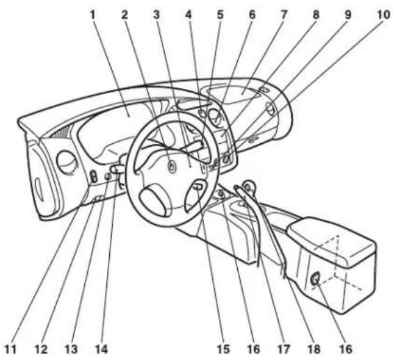
- Instrument cluster → p. 104
-
Ignition switch → p. 145
-
Supplemental restraint system-air bag (For driver's seat) → p. 87 Horn switch → p. 130
- Hazard warning flasher switch → p. 121
- Windshield wiper and washer switch → p. 124
- Vents → p. 231
- Supplemental restraint system-air bag (For front passenger's seat) → p. 87
- Audio
- Rear window defroster switch → p. 123
- Air conditioning → p. 232
- Fog light switch → p. 121
- Hood release lever → p. 41
- Instrument panel light dimmer control → p. 122
- Combination headlight, dimmer and turn-signal lever → p. 117
- Cruise control lever → p. 111
- Accessory socket → p. 207
- Parking brake lever → p. 165
- Gearshift or selector lever → p. 149, 154
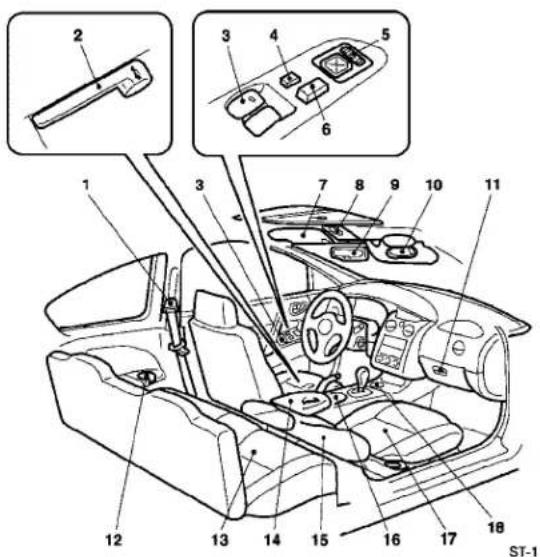
Interior
-
Seat belt → p. 66
Adjustable seat belt shoulder anchor (for front seats) → p. 71 -
Remote trunk lid release → p. 36
-
Power window switch → p. 43
-
Window lock switch → p. 44
-
Electric remote-controlled outside mirror switch → p. 184
-
Power door lock switch → p. 34
-
Sun visor → p. 205
-
Sunroof switch (for vehicles with sunroof) → p. 45 Dome light (for vehicles without sunroof) → p. 127
-
Inside day/night rearview mirror → p. 173 Electrochromic inside rearview mirror (if so equipped) → p. 174 Dome light (for vehicles with sunroof)
-
Vanity mirror → p. 206
-
Glove compartment → p. 210
-
Cup holder (for rear seat) → p. 208
-
Rear seat → p. 64
-
Center console with lid → p. 211
-
Supplemental restraint system-side air bag → p. 87 (for front seats, if so equipped)
-
Cup holder (for front seats) → p. 208
-
Front seat
-
Ash receptacle receiver.
8 INTRODUCTION
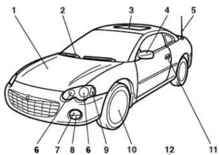
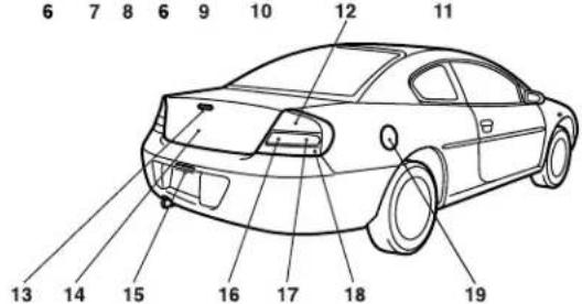
Outside
-
Engine compartment → p. 253 Engine hood → p. 41
-
Windshield wiper and washer → p. 124
-
Sunroof (if so equipped) → p. 45
-
Outside rear-view mirrors → p. 184
-
Whip antenna → p. 215
-
Headlights → p. 117, 288, 289
-
Front turn signal lights and parking lights → p. 117, 291
-
Fog lights → p. 118
-
Front side marker lights → p. 292
-
Tire inflation pressure → p. 326
Changing tires → p. 264
Tire rotation → p. 330
Tire chains → p. 331
Wheel covers (if so equipped) → p. 262
- Locking and unlocking → p. 26
Keyless entry system → p. 29
-
Stop and tail lights → p. 287
-
High-mounted stop lights → p. 296
-
Trunk lid → p. 35
-
License plate lights → p. 296
-
Back up lights → p. 287
-
Rear turn signal lights → p. 287
-
Rear side-marker lights → p. 287
-
Fuel filler → p. 39
Trunk Area
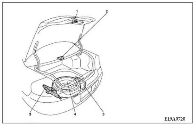
- Inside emergency trunk release handle → p. 37
- Trunk light p. 297
- Jack → p. 261
- Spare tire → p. 261
- Tools → p. 260
10 INTRODUCTION
QUICK INDEX
If this warning light comes on...
NOTE: These warning lights will illuminate for a few seconds for a bulb check when the ignition key is first turned on.
| Warning light Do this Ref. page | ||
 Anti-lock braking system Anti-lock braking system | ·Park the vehicle in a safe place and turn off the engine.Test the system as described on page 111.·If the light does not go out after the test, or if it illuminates again, have your vehicle inspected at an authorized dealer.·When this light comes on, the anti-lock braking system is not functioning and only the ordinary braking system is functioning. | P.111 |
 Brake warning light Brake warning light | ·If this light comes on while driving, check to see that the parking brake is fully released.·If this light stays on after releasing the parking brake, stop and check the brake fluid level is correct.·If the brake fluid level is correct, call an authorized dealer for assistance. | P.115 |
 Oil pressure warning light Oil pressure warning light | ·If this light comes on while driving, park your vehicle in a safe place and stop the engine immediately.Call an authorized dealer for assistance. | P.112 |
If this warning light comes on...
| Warning light Do this Ref. page | ||
 Charging system warning light Charging system warning light | ·Park the vehicle in a safe place and turn off the engine.Check the alternator belt.If the belt is loose, broken, missing, or if the light remains on when the ignition key is turned back on, call an authorized dealer for assistance. | P.112 |
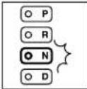 "N" indicator light in the instrument cluster flashes rapidly (twice per second) "N" indicator light in the instrument cluster flashes rapidly (twice per second) | ·Park the vehicle in a safe place.Idle the engine until the warning light goes off. If the light does not go off, have your vehicle inspected at an authorized dealer. | P. 157 |
12 INTRODUCTION
If this warning light comes on...
| Warning light Do this Ref. page | ||
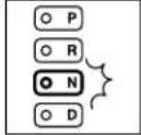 “N” indicator light in the instruemnt cluster flashes slowly (once per second) “N” indicator light in the instruemnt cluster flashes slowly (once per second) | ·Have the vehicle inspected at an authorized dealer as soon as possible. | P. 157 |
| SERVICE ENGINE SOONMalfunction indicator light (“SERVICE ENGINE SOON”) | ·Your vehicle will usually be drivable and not need towing, have the engine system checked at an authorized dealer as soon as possible.If the vehicle is not drivable, contact Emergency Roadside Service (ERS), authorized dealer, or local towing company for assistance. | P.113 |
| SRSAir bag warning light | ·Have the air bag system checked at an authorized dealer. P. 114 | |
 Traction control system warning light Traction control system warning light | ·It is not necessary to stop the vehicle immediately but we recommend that you have the system checked at an authorized dealer as soon as possible. | P.116 |
If you hear the sound...
natural_image
Cartoon illustration of a person in a suit waving, with sound waves above (no text or symbols)| Sound Do this Ref. page | ||
| If you hear a chime constantly when the driver's door is opened. | "Key reminder chime"A chime will sound if the driver's door is opened while the ignition key is in the "LOCK" or "ACC" position.Remove the key to stop the chime.OR"Headlight reminder chime"A chime will sound if the driver's door is opened when the ignition key is in the "LOCK" or "ACC" position or removed from the ignition switch with the lights on.If the driver's door is closed, the chime will stop | P. 27, 146P.118 |
14 INTRODUCTION
If you hear the sound...
| Sound Do this Ref. page | ||
| If you hear a metallic sound (squeal) when you depress the brake pedal while driving. | “Brake pad wear alarm”The brake pads have worn down near the serviceable limit.Have the brake pads replaced at an authorized dealer. | P. 168 |
| If you hear a chime from the engine compartment continuously while the engine is on. | “Brake system (hydraulic brake booster) warning chime (Vehicle with anti-lock braking system)”The brake circuit may not be operating correctly.If this chime does not stop after a few minutes, carefully stop the vehicle in a safe location and contact your nearest authorized dealer. | P.115 |
If you hear the sound...
| Sound Warning light Do this Ref. page | |||
| If you hear a chime while the engine is on, see the warning light in the instrument cluster. |  | "Seat belt reminder/warning chime"If the driver's seat belt remains unfastened 1 minute later, the chime will sound intermittently (12 times). If the driver's seat belt remains unfastened while the vehicle is being driven, the chime will sound as a warning each time the vehicle stops and starts. | P.116 |
 | "Low-fuel warning chime"Fuel is low. Add fuel as soon as possible. | P. 40, 111 | |
 | "Washer fluid level chime"The windshield washer level is low. Add fluid. | P.117 | |
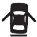 | "Door-ajar warning chime"Door or trunk is not properly shut.If you shut the door or trunk, the chime will stop. | P. 27, 110 | |
 | "Trunk-ajar warning chime"Trunk is not properly shut.If you shut the trunk, the chime will stop. | P.36 | |
16 INTRODUCTION
If this problem occurs...
| Problem Do this Ref. Page | ||
Cannot turn the key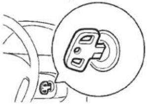 | (1)“LOCK” to “ACC”Turn the key while slightly turning the steering wheel right and left.(2)“ACC” to “LOCK”Vehicle with automatic transaxleCheck the position of gear selector lever.The key cannot be removed unless the gear selector lever is set to the “P” (PARK) position.Vehicle with manual transaxlePlace the key at the “ACC” position. Push the key in and turn it. | P. 147 |
| Cannot shift the gear selector lever from the “P” (PARK) position | Shift the gear selector lever while depressing the brake pedal. Check if the ignition key is in the “ON” position. | P. 150, 155 |
The windows are fogged up. | 1.Set the heater/air conditioning mode selection dial to the “↗” or “↘” position.2.Turn on the blower. | P. 240 |
If this problem occurs...
| Problem Do this Ref. page | ||
| The engine does not start.The lights do not come on or dim.The horn does not honk or weak sound. | The battery may have a weak charge. P. 273 | |
The engine coolant temperature gauge indicator enters the “H” (hot) position.Steam comes out of the engine compartment.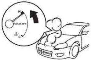 | The engine is overheated.Carefully stop the vehicle in a safe place.If necessary call for roadside assistance. | P. 272 |
18 INTRODUCTION
If this problem occurs...
| Problem Do this Ref. page | ||
| The vehicle is stuck in sand, mud, or snow. | 1. Carefully rock the vehicle by shifting the transmission from low to reverse.WARNING1.When attempting to rock your vehicle out of a stuck position, be sure that no one is near the vehicle. The rocking motion may cause the vehicle to suddenly lurch forward or backward, and injure bystanders.2.Avoid racing the engine or spinning the wheels.Prolonged efforts to free a stuck vehicle may result in overheating and transaxle failure.If the vehicle remains stuck after several rocking attempts, have a towing service pull the vehicle out. | P. 257 |
| The brakes are not functioning properly after crossing a puddle or stream. | Dry out the brakes by driving slowly while lightly depressing the brake pedal. | — |
If this problem occurs...
| Problem Do this Ref. page | ||
| The automatic transaxle does not shift when accelerating and/or the vehicle does not easily begin to move. | There may be a problem in the automatic transaxle.Have the vehicle inspected by an authorized dealer.1.Vehicles with automatic transaxleShift the lever into “2” (SECOND) position when starting the vehicle. If the vehicle is on a level road, shift the lever back to “D” (DRIVE) position.2.Vehicles with Autostick automatic transaxleShift the lever into 2nd gear of the Autostick mode when starting the vehicle. If the vehicle is on a level road, shift the lever back to “D” (DRIVE) position.(These methods may or may not work depending on the contents of malfunction.) | P. 154, 162 |
A tire is punctured.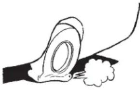 | 1.Park the vehicle in a safe place where the surface is flat and level.2.Replace the flat tire with the spare tire. | P. 264 |
LOCKING AND UNLOCKING
CONTENTS
■ Keys....2 3
■ Sentry Key 23
■ Door locks (Manual) 26
□ To lock the door without using the key ..... 2 6
□ To lock the door with the key
(Driver's side only)....27
□ To lock the door from the inside . . . . . . . . . . . 2 8
■ Keyless entry system ..... 2 9
□ Confirmation function ..... 2 9
□ Using the panic alarm....3 1
☐ Procedure for replacing keyless transmitter battery....3 2
■ Power door locks....3 4
□ Locking and unlocking with the door lock switch. 34
□ Locking and unlocking with key or inside lock knob. 35
□ Locking by means of the inside lock knob ..... 3 5
■ Trunk lid. 35
□ Remote trunk lid release. 36
□ Inside emergency trunk release ..... 3 7
■ Fuel filler 39
■ Engine hood release....4 1
■ Power windows 43
□ Driver switch. 4 4
22 LOCKING AND UNLOCKING
□ Passenger switch....4 5
■ Sunroof (if so equipped) 45
□ To tilt up. 45
□ To tilt down....46
□ To open. 46
□ To close. 46
□ Sunshade....47
Theft-alarm system 48
□Armed stage 48
□ Alarm stage. 50
□ Disarmed stage....5 1
□ Testing the theft-alarm system. 52
KEYS
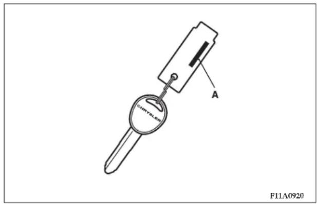
Two keys are provided.
The keys fit all locks. Keep one in a safe place as a spare key.
NOTE: The key number (A) is stamped on the plate as shown in the illustration.
Make a record of the key number and store the key and key number plate in a separate place so that you can order a key from your authorized dealer if the original keys are lost.
SENTRY KEY
The sentry key is designed to significantly reduce the possibility of vehicle theft. The purpose of the system is to immobilize the vehicle if an invalid start is attempted. A valid start attempt can only be achieved (subject to certain conditions), using a key "registered" to the sentry key system.
All of the keys provided with your new vehicle have been programmed to the vehicle electronics.
24 LOCKING AND UNLOCKING
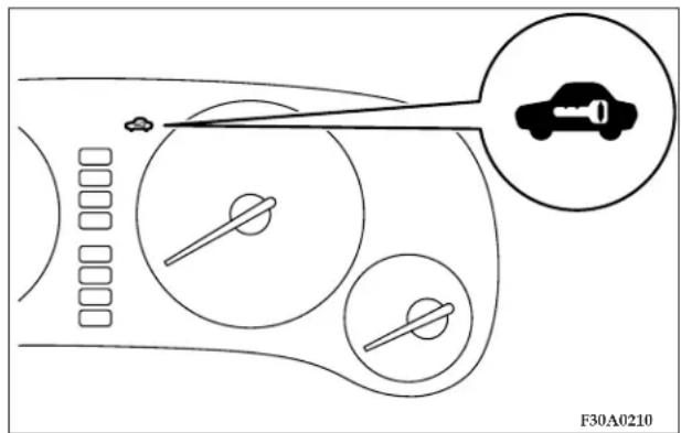
NOTE
-
In the following cases, the vehicle may not be able to receive the registered ID code from the key. This means the engine will not start even when the registered key is turned to the "START" position:
-
When the key comes into contact with a metallic or magnetic object.
- When the key comes into contact with another immobilizing key, or with some other transponder.
In case like these, the theft-alarm indicator (located in the instrument cluster) will blink after 10 seconds. The theft-alarm indicator will flash for approximately 30 seconds and then go off.
Remove the above object from the key and turn the key back to the "ACC" or "LOCK" position. Then try again to start the engine. If the engine does not start, consult an authorized dealer.
- Since there is a transponder built into the key, be careful not to cause shock to the key, such as by dropping it or by putting heavy objects on top of it.
- Do not leave the key where it may be exposed to heat caused by the high temperature and high humidity.
- Sentry key is not compatible with remote starting systems. Use of these systems may result in vehicle starting problems and a loss of security protection.
- A system failure is suspected when the ignition key is turned to the "START" position, the engine does not start. In such a case, consult an authorized dealer.
CAUTION!
Do not make any alterations or additions to the sentry key system. Any alterations or additions could cause failure of the sentry key.
Replacement keys
NOTE:
Only keys that have been programmed to the vehicle electronics can be used to start the vehicle.
If you lose the key, you can order a key from your authorized dealer by referring to the key number. You will also need to register the key ID code.
Your dealer can register the key ID's or you can follow the "Customer Key Programming" procedure.
You are provided with 2 keys, but you may add up to 6 more keys, for a total of 8 registered to the vehicle.
Customer Key Programming
You can program new keys to the system if you have two valid keys by doing the following:
NOTE:
A valid key is one that will start and run the vehicle.
-
Insert the first valid key into the ignition and turn the ignition to the "ON" position for 5 seconds.
-
Turn the ignition to the "OFF" position and remove the first key.
-
Insert the second valid key and switch the ignition in the "ON" position within 7 seconds. Theft-alarm indicator will blink twice.
Turn the ignition to the "OFF" position and remove the second key.
- Insert a blank Sentry Key into the ignition and switch the ignition in the "ON" position within 7 seconds.
The theft-alarm indicator will illuminate for about 3 seconds when the registration is completed.
26 LOCKING AND UNLOCKING
If an error occurs, the indicator will flash 3 times.
- Repeat step 4 if you want to register additional keys. Be sure to complete the entire registration process within 30 seconds after the theft-alarm indicator flashes in step 3.
General Information
Your sentry key operates on a radio frequency subject to Federal Communications Commission (FCC) Rules. This device complies with Part 15 of the FCC Rules. Operation is subject to the following two conditions.
- This device may not cause harmful interference.
- This device must accept any interference, including interference that may cause undesired operation.
DOOR LOCKS (MANUAL)
To lock the door without using the key
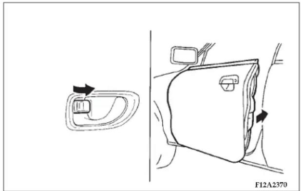
natural_image
Diagram showing a car door handle and side panel with directional arrows, no text or symbols presentTo lock the door, set the inside lock knob to the locked position, and close the door.
Be sure the keys are not inside the vehicle before closing the door.
Key reminder chime
After the ignition switch is off, if the driver's door is opened while the ignition key is in the ignition, a chime will sound to remind you to remove the key.
Forgotten-key prevention mechanism
If the inside lock knobs on the doors are set to the locked position and the driver's door or passenger's door is closed while the key is still in the ignition switch, the lock will automatically be released.
Door-ajar warning chime
When the vehicle is moving at more than 5 mph (8 km/h) and the door or the trunk is open, a chime will sound to inform the driver that the door is not properly shut.
To lock the door with the key (Driver's side only)
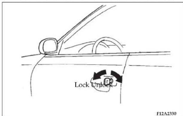
Rotate the key toward the front of the vehicle to lock the door. After checking that the door is locked, turn the key back to the center and remove it from the lock cylinder.
28 LOCKING AND UNLOCKING
To lock the door from the inside
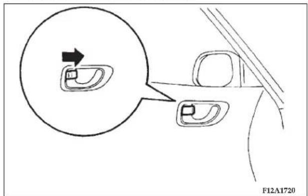
Move the inside lock knob to the locked position (so that the red mark cannot be seen) to lock the door. All doors should be kept locked while driving.
The locked front driver's side door can be opened by pulling its inside door handle without unlocking the inside lock knob. This feature is applicable to the driver's door only.
CAUTION!
• Make sure the doors are closed; driving with doors not completely closed is very dangerous.
- Never leave a child in the vehicle unattended.
KEYLESS ENTRY SYSTEM
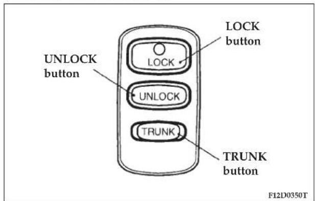
Press the keyless transmitter button(s), and all doors will be locked or unlocked as desired. The PANIC button can also help you signal for attention.
To lock the doors
Press the LOCK button, and all doors will be locked. When they are locked with the reading light in the "OFF" position, the reading light blinks twice. All turn signal lights also blink twice and the horn sounds once.
To unlock the doors
Pressing the UNLOCK button once will unlock the driver's door only. Press the UNLOCK button one more time, and all doors will be unlocked.
When the driver's door only, or all doors are unlocked with the reading light in the "OFF" position, the reading light will illuminate for 30 seconds.
All turn signal lights will also blink once.
To unlock the trunk lid
Press the TRUNK button twice within five seconds and the trunk lid will be unlocked. The trunk lid must be closed manually after it has been unlocked.
Confirmation function
The confirmation functions provided by the horn and turn signal lights after operation of the keyless entry system can each be turned ON or OFF as desired. The following procedures must be performed with the key removed from the ignition switch. At the end of each procedure, a chime sounds once if the function has been turned ON or twice if the function has been turned OFF.
Horn deactivation/reactivation
The confirmation function can be set in the following three ways.
Each time the confirmation function is set, a buzzer will sound to tell you the condition of the confirmation function.
One buzzer: The horn will sound if the doors are locked with the keyless entry system. The horn will sound regardless of whether the doors are locked or unlocked.
Two buzzers: The horn will not sound, even if the doors are locked with the keyless entry system.
Three buzzers: The horn will sound if the doors are already locked and the keyless entry system is used again.
In this mode, the horn will only sound when the keyless entry LOCK switch is pressed again to reconfirm that the doors are locked.
-
Press the LOCK switch (1) for 4 to 10 seconds and press the UNLOCK switch (2) during this period.
-
Release the LOCK and UNLOCK switches at the same time.
Turn signal light feature-ON/OFF
The confirmation function provided by the turn signal lights when the doors are locked and the confirmation function provided when they are unlocked can be deactivated/reactivated separately.
At the end of each procedure, a buzzer sounds once if the function has been reactivated or twice if the function has been deactivated.
- Press the UNLOCK button for 4 to 10 seconds and press the LOCK button within this period.
- To turn ON/OFF the function provided when the doors are locked, release the LOCK button and then release the UNLOCK button.
- To turn ON/OFF the function provided when the doors are unlocked, release the UNLOCK button and then release the LOCK button.
F12D0360
Using the panic alarm
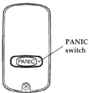
If you are near your vehicle and feel threatened, you may activate the alarm to call attention.
- Press the PANIC button.
- The headlights will blink on and off and the horn will sound intermittently for about 3 minutes.
- To turn off the alarm, press any button on the keyless transmitter.
LOCKING AND UNLOCKING 31
NOTE
- The keyless entry system will not operate if the key is in the ignition switch.
- The keyless transmitter will operate within about 12 m (39 ft) from the vehicle. However, the operating range may change if the vehicle is located near a TV transmitting tower, power station, or radio broadcasting station.
- If the UNLOCK button is pressed when all doors are closed and no door is opened within approximately 30 seconds, re-locking will automatically occur.
- If the following conditions are observed after pressing a keyless transmitter button, the battery in the keyless transmitter may need to be replaced.
• The doors cannot be locked or unlocked.
• The trunk lid cannot be unlocked.
• The panic alarm cannot be operated.
5. Do not leave the keyless transmitter where it may be exposed to heat caused by the direct rays of the sun.
6. If your transmitter is lost or damaged, please contact an authorized dealer for a replacement.
32 LOCKING AND UNLOCKING
- If you wish to add another transmitter, contact an authorized dealer. A maximum of 4 keyless transmitters may be programmed for your vehicle.
CAUTION!
The keyless transmitter is a precision electronic device. Therefore;
- Avoid impact to the transmitter.
- Keep the transmitter dry.
- Do not disassemble the transmitter.
Your keyless entry system operates on a radio frequency subject to Federal Communications Commission (FCC) Rules. This device complies with Part 15 of the FCC Rules. Operation is subject to the following two conditions.
• This device may not cause harmful interference.
- This device must accept any interference, including interference that may cause undesired operation.
CAUTION!
Changes or modifications not expressly approved by the manufacturer for compliance could void the user's authority to operate the equipment.
Procedure for replacing keyless transmitter battery
F12D0390T
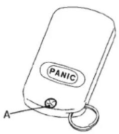
- Remove the transmitter case mounting screw (A) and gently pry open the case.
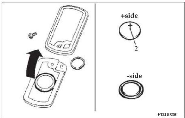
- Remove the discharged battery from the panic button side of the case half.
- Install a new battery with its positive + side (2) down.
Coin type battery CR2032 used
- Close the transmitter case firmly and tighten the mounting screw.
- Check the keyless entry system for operation.
NOTE
- You may purchase a battery at any local store that sells batteries.
- Your authorized dealer can replace the battery for you if necessary.
CAUTION!
When the transmitter is opened, be careful to keep water, dust, etc. out. In addition, do not touch the internal components.
34 LOCKING AND UNLOCKING
POWER DOOR LOCKS
Locking and unlocking with the door lock switch
Driver side switch Passenger side switch
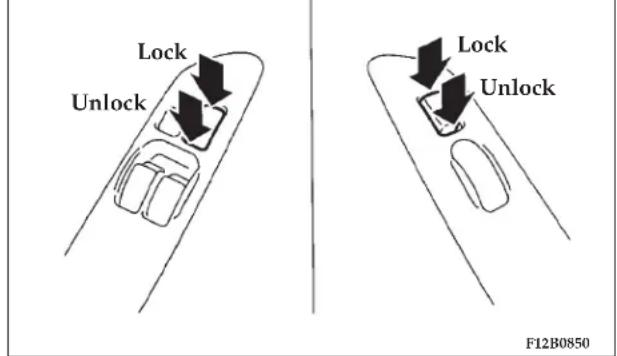
All of the doors can be locked or unlocked by pressing the power door lock switch on the driver's or the passenger's door.
Rolling lock feature
If the vehicle's speed goes over 15 mph (25 km/h), all the doors will lock automatically.
NOTE: The Rolling lock function can be turned ON or OFF by the following procedures:
- Insert the key in the ignition. Leave key in "OFF" position.
- Close both the driver's and passenger's doors.
- Press and hold the driver's (central) door lock switch until a chime sounds (10 seconds). The Rolling lock feature will be switched to ON (if it is OFF) or OFF (if it is ON).
If the chime sounds once, the Rolling lock feature is ON. If the chime sounds twice, the Rolling lock feature is OFF.
Locking and unlocking with key or inside lock knob
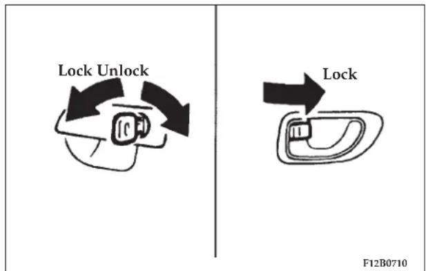
Using the key to lock or unlock the driver's door will automatically lock or unlock all of the doors.
- Turn the key inserted in the driver's door lock once in the unlocking direction, and the front driver's door will be unlocked.
- Give another turn in the unlocking direction, and both doors will be unlocked.
Locking by means of the inside lock knob
Place the inside lock knob of the driver's door in the locked position, and both doors will be locked.
TRUNK LID
WARNING!
- It is dangerous to drive with the trunk lid open since carbon monoxide (CO) gas can enter the cabin. CO is an invisible, odorless gas that can cause unconsciousness and even death.
- Do not allow children to have access to the trunk, either by climbing into the trunk from outside or through the inside of the vehicle. Always close the trunk lid when your vehicle is unattended. If trapped in the trunk, it is possible to escape from the trunk by using the inside emergency trunk release handle. (See “Inside emergency trunk release” on Page 37).
36 LOCKING AND UNLOCKING
CAUTION!
Do not stand behind the exhaust pipe when loading and unloading luggage. Heat from the exhaust could lead to burns.
To open the trunk lid
Press the TRUNK switch twice within five seconds. (Refer to "Keyless entry system" on page 29.)
The trunk lid will unlock and rise slightly.
Lift it to open.
To close the trunk lid
Lower the trunk lid and push down with both hands until it is locked.
Trunk-ajar warning chime
When the vehicle is moving at more than 5 mph (8 km/h) and the trunk lid is open, a chime will sound to inform the driver that the trunk lid is not properly shut.
Remote trunk lid release
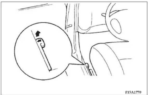
Pull the trunk lid release lever, located to the left of the driver's seat, up to open the trunk lid.
natural_image
Technical line drawing of a mechanical component with an inset showing a pin inserted into a slot (no text or symbols)CAUTION!
Do not operate the trunk lid release lever while the vehicle is moving. If the trunk lid opened, luggage could fall onto the road and cause an accident.
Inside emergency trunk release
natural_image
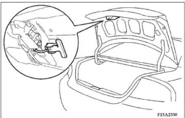
Technical line drawing of a vehicle interior showing a bracket and seat assembly, with an inset close-up highlighting the component (no text or symbols present)The emergency trunk release is designed to provide a way to open the trunk lid from inside the trunk. It was developed to help prevent death and serious heat-related injuries, including brain damage, especially for children who might become locked inside a vehicle trunk.
The illuminated "T" shaped yellow emergency trunk release handle (see illustration) is mounted near the latch inside the trunk lid. Velcro keeps the handle secure in its holder.
The handle glows in the dark after exposure to sunlight. You and your family should familiarize yourselves with the location and operation of the emergency trunk release handle. Children should be taught not to play in or around vehicles.
WARNING!
- Children should never be left unsupervised in or around vehicles.
- Unsupervised children could lock themselves in an open vehicle or trunk.
- People trapped inside a vehicle, or trunk, even if only for a short period of time, can quickly die from suffocation or heat stroke, especially on hot days. Interior temperatures in vehicles can rise in minutes.
- Keep your vehicle doors locked and the trunk closed when not in use. Keep your vehicle keys away from children.
38 LOCKING AND UNLOCKING
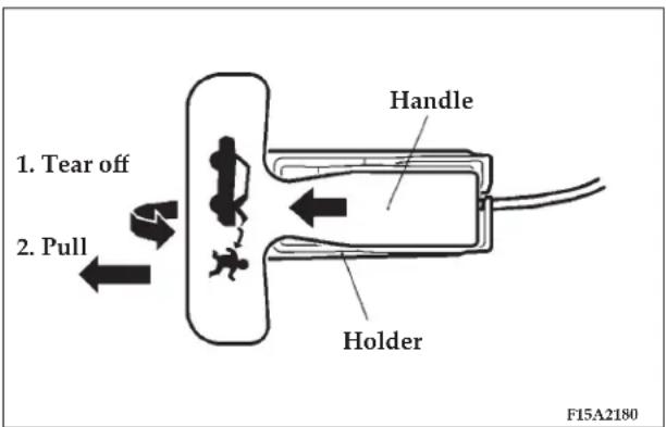
To open the trunk from inside the trunk, tear off the illuminated "T" handle from its holder by pulling in the direction of the arrow (1). Then pull the handle in the direction of the arrow (2). Push up on the trunk to exit.
CAUTION!
- When loading objects in the trunk, position them so that they will not contact the emergency trunk release handle when closing the trunk. This will prevent damage to the handle that could render it inoperable.
- Always keep the handle in its holder when operating the vehicle to prevent trunk cargo from moving the handle that might result in the opening of the trunk lid.
FUEL FILLER
natural_image
Line drawing of a car with a magnified circular inset showing a curved arrow (no text or symbols)WARNING!
Turn off the engine while refueling. Do not smoke and do not operate other ignition sources while refueling.
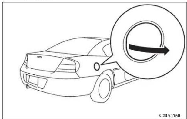
The fuel filler is located on the right rear of the body. Hook a finger behind the fuel filler door, and pull the door toward you.
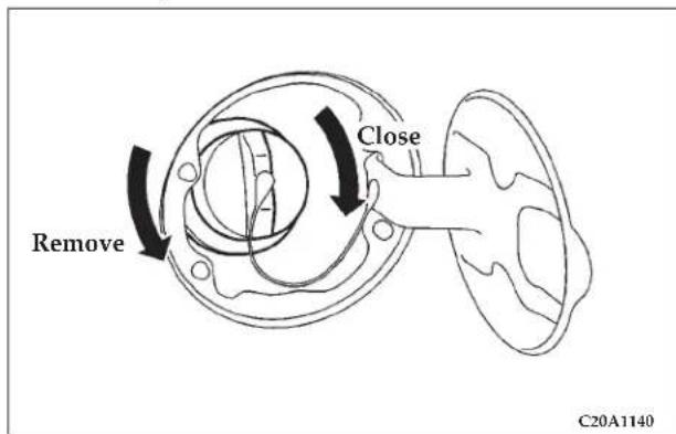
Remove the fuel tank filler tube cap slowly by turning it counterclockwise.
To close, securely turn the fuel tank filler tube cap clockwise until you hear clicking sounds, and gently push the fuel filler tank door into the closed position.
40 LOCKING AND UNLOCKING
Low fuel warning chime
If a chime sounds when the low fuel warning light is on, that means the fuel is low.
NOTE: If the low fuel warning light goes off, then comes back on again, the chime will not sound.
Fuel tank capacity 61.7 L (16.3 gal)
CAUTION!
- As the fuel system may be under pressure, remove the fuel tank filler tube cap slowly. Removing the cap slowly relieves any pressure or vacuum that might have built up in the fuel tank. If the cap is venting vapor or if you hear a hissing sound, wait until it stops before completely removing the cap. Otherwise, fuel may spray out and injure you or others.
- If you need to replace the fuel tank filler tube cap, use only a cap specified for your model vehicle.
- To avoid fuel spillage and overfilling, do not "top-off" the fuel tank again and again after filling.
NOTE: If the fuel tank filler tube cap is not tight while driving, the "Malfunction indicator light (SERVICE ENGINE SOON)" may illuminate when the onboard diagnostic (OBD) system performs its self check.
Always tighten the fuel tank filler tube cap until you hear clicking sounds. The indicator light will go off after driving several times. If the indicator light does not go off, contact your authorized dealer as soon as possible.
ENGINE HOOD RELEASE
natural_image
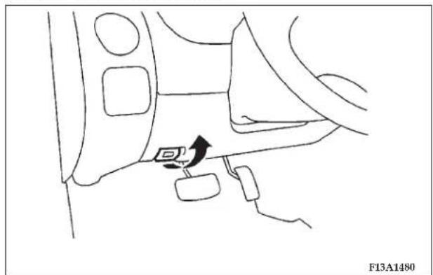
Diagram of a car interior showing a directional arrow and labeled component (F13A1480), no readable text or symbols beyond the label.The engine hood release lever (located under the instrument panel near the driver's door) is used to unlock the engine hood.
Pull the lever toward you to release the engine hood latch.
WARNING!
- Never release the engine hood using the release lever while the vehicle is in motion.
- Do not operate the vehicle unless the engine hood is latched.
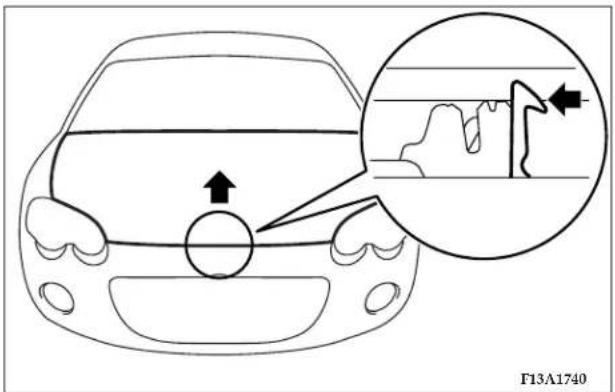
Release the safety lever and lift the engine hood.
42 LOCKING AND UNLOCKING
NOTE: Only open the engine hood when the wipers are at their parked position to prevent damage to the engine hood and wipers.
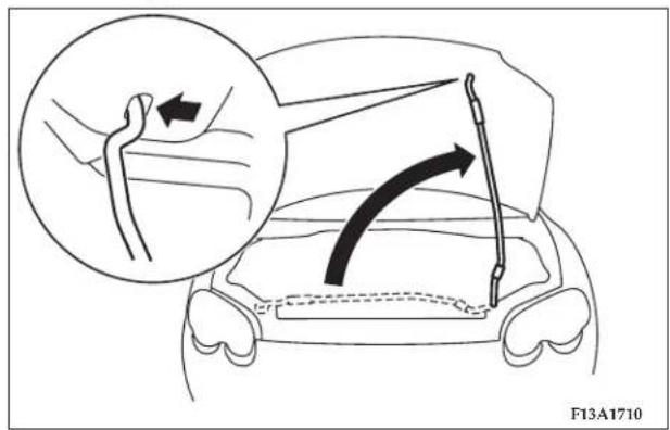
Support the engine hood with the hood prop by inserting the hood prop securely in the opening in the hood marked with an arrow.
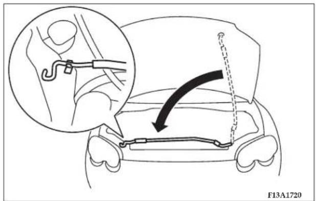
To close, unlatch the hood prop from the engine hood and place the hood prop in its retainer. Slowly lower the engine hood to about 12 inches (30 cm) from the closed position, then release it. The hood should latch from its own weight.
NOTE: If this does not latch the engine hood, release it from a slightly higher position.
CAUTION!
Be careful that hands or fingers are not trapped when closing the engine hood.
POWER WINDOWS
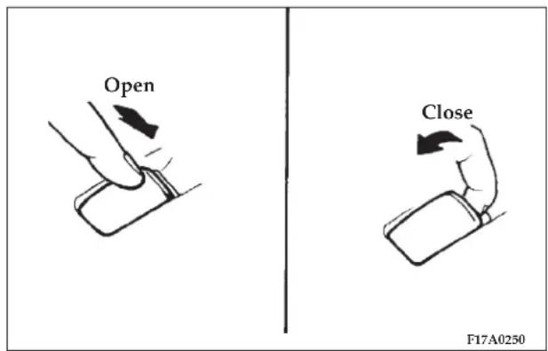
NOTE
- The windows can be operated when the ignition key is in the "ON" position. The door windows can be opened
or closed for a 30-second period even after the ignition switch is turned off. However, once the driver's door or the front passenger's door is opened, the windows cannot be operated until the ignition switch is turned on again.
- Never try to operate the driver switch and passenger switch in opposing directions at the same time. Doing so will cause the window to freeze in position.
- Repeated operation with the engine stopped (key "ON") will run down the battery. Operate the window switches while the engine is running.
WARNING!
- Before operating the power windows, make sure that nothing can be trapped (head, hand, finger, etc.) in the window.
- Never leave the vehicle without removing the key.
• Never leave a child in the vehicle alone.
44 LOCKING AND UNLOCKING
Driver switch
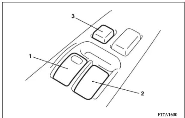
The main driver switch can be used to operate both door windows.
Windows will move while the switch is being operated and stop when the switch is released.
- Driver's door window switch
(To fully open the driver's door window, it is not necessary to hold the switch down for the entire time the window is being lowered.)
- Passenger's door window switch
- Window lock switch
(When this switch is pressed into lock mode, the passenger switch cannot be used to open or close the door window, and the driver switch can open or close either window. To unlock, press the window lock switch again.)
WARNING!
Before driving with a child in the vehicle, be sure to press the window lock switch to make the window switches inoperative. A child may tamper with the switch at the risk of their hands or head becoming trapped by the window.
Passenger switch
natural_image
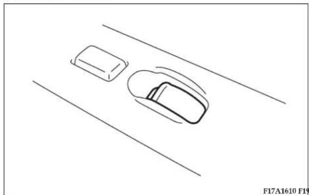
Top-down line drawing of a car on a road with two rectangular blocks nearby (no text or symbols)The passenger switch can be used to operate the passenger door window.
SUNROOF (IF SO EQUIPPED)
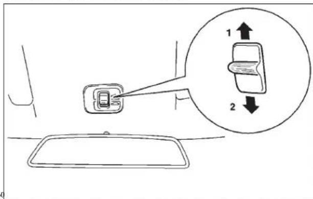
The sunroof can be opened and closed with the ignition key in the "ON" position.
To tilt up
When the sunroof switch (1) is pressed, the back of the sunroof automatically goes up for inside ventilation. To stop the sunroof partway, push the sunroof switch (2).
NOTE: Before tilting the sunroof, completely open the sunshade. Otherwise you will not have good ventilation.
46 LOCKING AND UNLOCKING
To tilt down
Press the sunroof switch (2).
To stop the sunroof partway, release the sunroof switch.
To open
When the sunroof switch (1) is pressed, the back of the sunroof automatically goes up.
When the sunroof switch (1) is pressed a second time, the sunroof automatically opens completely.
To stop the sunroof partway, press the sunroof switch (2).
To close
The sunroof closes while the sunroof switch (2) is being pressed.
To stop the sunroof partway, release the switch.
NOTE
-
The sunroof can be operated when the ignition key is in the "ON" position. The sunroof can be opened or closed for a 30-second period after the ignition switch is turned off. However, once the driver's door or the passenger's door is opened, the sunroof cannot be operated until the ignition switch is turned on again.
-
If the battery cable is disconnected or the fuse is replaced while the sunroof is open, the sunroof will not close normally even after reconnecting the battery cable. In this case, use the following steps.
Press the switch (2) repeatedly to close the sunroof completely. The sunroof will resume its normal operation after this procedure is completed.
Sunshade
natural_image
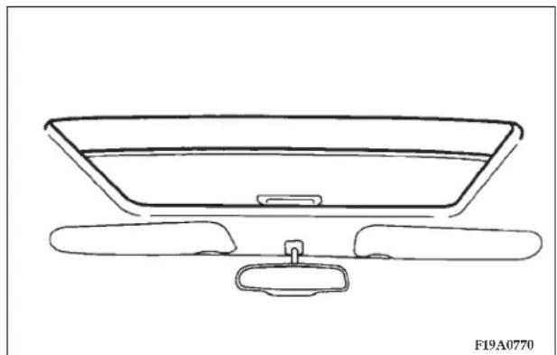
Line drawing of a car front view showing dashboard, rear seats, and seat (no text or symbols)The sunshade can be opened or closed manually while the sunroof is closed.
NOTE: The sunshade will operate together with the sunroof only when the sunroof is opened.
CAUTION!
Do not attempt to close the sunshade when the sunroof is opened.
WARNING!
- When leaving the vehicle unattended, be sure to close the sunroof and remove the ignition key.
- Before operating the sunroof, make sure that nothing can be trapped (head, hand, finger, etc.).
- Never leave a child (or other person who is incapable of safely operating the sunroof switch) in the vehicle alone.
NOTE
- Do not stick your head, hand or anything else out of the sunroof opening.
- After washing the vehicle or after there is rain, be sure to wipe off any water that is on the sunroof before operating it.
48 LOCKING AND UNLOCKING
- Do not try to operate the sunroof if it is frozen closed (after snowfall or during extreme cold).
- Do not sit on or place heavy luggage on the sunroof or roof opening edge.
- Do not apply any force that may cause damage to the sunroof.
- When waxing your vehicle, be careful not to put any wax on the weatherstrip (black rubber) around the sun-roof opening. If stained with wax, the weatherstrip cannot maintain a weatherproof seal with the sunroof.
- Release the switch when the sunroof has reached a completely open or completely closed position.
THEFT-ALARM SYSTEM
The theft-alarm system is designed to provide protection from unauthorized entry into the vehicle. This system is operated in three stages: the first is the “armed” stage, the second is the “alarm” stage, and third is the “disarmed” stage. If triggered, the system provides both audible and visual alarm signals.
Armed stage
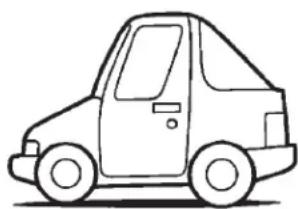
Park the vehicle and stop the engine. Arm the system as described below.
Arm the system and leave.
natural_image
Line drawing of a car in a side view, no text or symbols present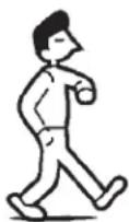
F30A0010
- Remove the key from the ignition switch.
-
Make sure the trunk lid is locked.
-
Lock the driver's and the passenger's door by using the key, power door lock switch, or the remote keyless transmitter.
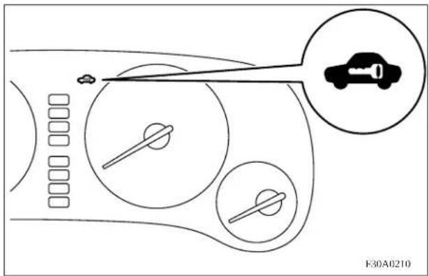
After completion of the steps above, the theft-alarm indicator (located in the instrument cluster) will illuminate for approximately 20 seconds and then go out, indicating that the system is armed.
NOTE
-
The system will be armed even if the trunk lid is opened, but when the system is set, be sure that the trunk lid is latched.
-
The system will be disarmed if, while the theft-alarm indicator is illuminated, the driver's door, the passenger's door is unlocked by using the key or keyless transmitter.
-
The system will be disarmed if, while the theft-alarm indicator is illuminated, the ignition key is turned to the "ON" or "ACC".
-
The system will not be armed if a door is not completely closed. If this happens, rearm the system as described above.
-
The trunk lid can only be unlocked by using the key or the remote keyless transmitter without triggering or disarming the system even after the system has been armed. When it is locked, the system will be rearmed.
-
The system will be armed even if the trunk lid is open, but when the system is set, be sure that the trunk lid is latched.
50 LOCKING AND UNLOCKING
- The driver should not arm the system until first confirming that all passengers have left the vehicle. If the driver arms the system while a passenger(s) in the vehicle, the alarm may be activated when the passenger(s) leave the vehicle.
Alarm stage
The alarm will be activated if any of the following occur while the vehicle is parked and the system is armed.
- The driver's or passenger's door is opened without using the key or the remote keyless transmitter.
- The trunk lid is opened without using the key or the remote keyless transmitter.
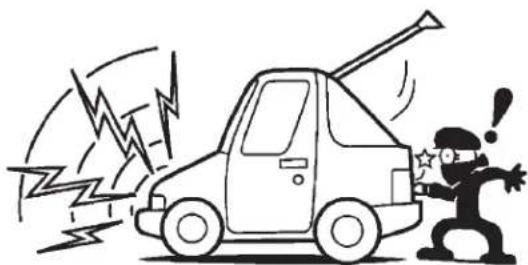
TYPE OF ALARM
When the alarm is activated:
Horn sounds!
Headlights blink on and off!
natural_image
Cartoon illustration of a person reacting to a car with a lightning bolt, no text or symbols presentF30A0020
- The headlights blink on and off for 3 minutes. After 3 minutes the headlights automatically shut off.
- The horn will sound intermittently for 3 minutes.
NOTE: The alarm will continue to operate for 3 minutes. At the end of that period, the alarm will automatically shut off to save battery power. The system will then be rearmed until the proper disarming step is taken.
Alarm deactivation
The alarm can be deactivated in the following ways.
- By turning the key (in the driver's, passenger's door or the trunk lid) in either direction (toward lock or unlock).
- By using the remote keyless transmitter to lock or unlock the door or trunk lid.
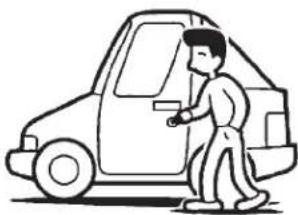
Disarmed stage
Disarm....by key (or by keyless transmitter)
natural_image
Line drawing of a person standing beside a car, no text or symbols presentF30A0040T
The system will be disarmed when either of the following steps are taken:
- The front driver's door, passenger's door or the trunk lid is unlocked by using the key or the remote keyless transmitter.
- The ignition key is turned to the "ACC" or "ON" position.
52 LOCKING AND UNLOCKING
- If the UNLOCK switch is pressed when all doors are closed and no door is opened within approximately 30 seconds, re-arming will automatically occur.
NOTE: Once the system has been disarmed, it cannot be rearmed except by repeating the arming procedure.
Testing the theft-alarm system
Use the following procedure to test the system:
- Lower the driver's window.
- Arm the system as explained in "Armed stage".
- Make sure that the theft-alarm indicator illuminates and goes off in approximately 20 seconds.
- Wait a few seconds and then unlock the driver's side door by using the inside door lock knob and opening the door.
-
Check to be sure that the horn sounds intermittently and the headlights blink on and off when the door is opened.
-
Disarm the system by unlocking the front driver's door, passenger's door or the trunk lid by using the key or the remote keyless transmitter.
NOTE: To make sure the alarm sounds when the trunk lid is opened, open the trunk lid by using the trunk lid release lever.
SEATS, SEAT BELTS, CHILD RESTRAINTS AND AIR BAGS
CONTENTS
■ Front seats. 5 5
□ To adjust seat forward or backward ..... 5 7
□ To recline the seatback....58
□ To adjust seat height (Driver's side only) ..... 6 1
□ To adjust lumbar support
(Driver's side only, if so equipped)....63
☐ For access to the rear seat
(passenger side entry). 6 3
■ Rear seats . . . . . . . . . . . . . . . . . . . . . . . . . . . . . . . . . . . . . . . . 6 4
□ Rear seat capacity....6 4
□ Fold down rear seatbacks....6 4
■ Head restraints .... 6 4
□ Adjustment of the head restraints . . . . . . . . . . 6 5
■ Seat belts. 6 6
□ UNIBELT restraint system. 67
□ UNIBELT instructions. 68
□ Adjustable seat belt shoulder anchor (front seats)....71
☐ Enhanced Driver Seat Belt Use Reminder System (BeltAlert™) 72
□ Seat belt extender. 73
■ Child restraints .... 7 4
□ Installing a child restraint system to a UNIBELT at the rear seat positions or the front passenger seat (With emergency/automatic locking mechanism) 80
54 SEATS, SEAT BELTS, CHILD RESTRAINTS AND AIR BAGS
□ Tether anchors for the child restraint system. . . . 8 3
□ Tether strap anchor installation....8 4
□ Children who have outgrown child restraint systems. 84
□ Seat Belts and Pregnant Women....8 5
■ Maintenance and inspection of seat belts ..... 8 6
■ Supplemental Restraint System (SRS) - air bag . .87
□ SRS servicing. 98
□ Transporting Pets. 100
Your vehicle has seat belts and other features that help protect you and your passengers in an accident. Seat belts are the most important safety device. When worn properly, seat belts can reduce the chance of serious injury or death in various types of crashes. For added protection during a severe frontal collision, your vehicle has a Supplemental Restraint System (SRS) with air bags for the driver and front seat passenger. The seats, head restraints, and door locks also are safety equipment, which must be used correctly. Always check the following before you drive:
- Everyone in the vehicle is properly wearing their seat belt.
- Infants and small children are properly secured in appropriate child restraints in the rear seat.
- All doors are closed and locked.
- Seat backs are fully upright, with head restraints properly adjusted.
No safety equipment can prevent all injuries or deaths that can occur in severe collisions, but by making sure all your passengers follow the instructions in this manual, you can help reduce the risk of injury.
FRONT SEATS
natural_image
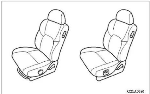
Line drawing of two car seat compartments with side panels and buttons, no text or symbols presentAdjust the driver's seat as far back as possible to a position that enables you to fully apply the pedals, easily control the steering wheel, safely operate the vehicle and also gives you a clear frontal view.
56 SEATS, SEAT BELTS, CHILD RESTRAINTS AND AIR BAGS
WARNING!
- Do not attempt to adjust the seat while driving. This can be dangerous.
- After adjusting the seat, make sure that the seat is securely locked into position.
- Be sure to have the seat adjusted by an adult. If it is adjusted by a child, the seat may not be properly locked into position.
WARNING!
- In order to reduce risk of serious or fatal injury in a collision, including from a deploying front passenger air bag, all front seat passengers should move the front passenger seat as far back as possible, all children 12 years old and under should ride restrained in the rear seat, and all children in rear-facing child restraints must ride in the rear seat.
- In order to reduce risk of serious or fatal injury in an accident, including from a deploying driver's side air bag, the driver should move the driver's seat as far back as possible, while still maintaining good visibility and good control of the steering wheel, accelerator and brake pedals.
NOTE: On vehicles with a power seat, to prevent the battery from running down, operate the power seat with the engine in operation.
To adjust seat forward or backward
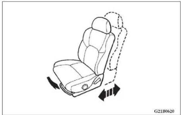
Type 1 (Manual)
natural_image
Line drawing of a car seat with directional arrows indicating motion (no text or symbols)Pull the seat adjusting lever and slide the seat forward or backward to the desired position. Release the adjusting lever to lock the seat in position.
SEATS, SEAT BELTS, CHILD RESTRAINTS AND AIR BAGS 57
WARNING!
To ensure the seat is locked securely, attempt to move the seat forward or backward without using the adjusting lever.
Type 2 (Power, driver's side only-if so equipped)
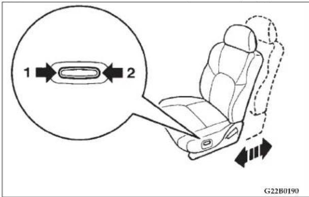
Push the switch to adjust the seat forward or backward to the desired position. Release the switch, and the seat will lock at that position.
58 SEATS, SEAT BELTS, CHILD RESTRAINTS AND AIR BAGS
- Backward
- Forward
CAUTION!
Operate the power seat with care not to have the hand or foot caught by the seat.
To recline the seatback
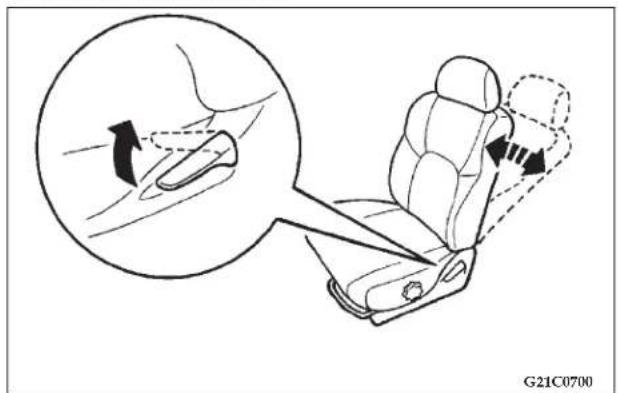
In order to recline the seatback, first lean your body forward slightly and pull the seatback lock lever up, and then lean backward to the desired position and release the lever. The seatback will lock in that position.
SEATS, SEAT BELTS, CHILD RESTRAINTS AND AIR BAGS 59
Memory reclining knob
When you fold down the seatback by using the memory reclining knob, the angle of the seatback will be memorized.
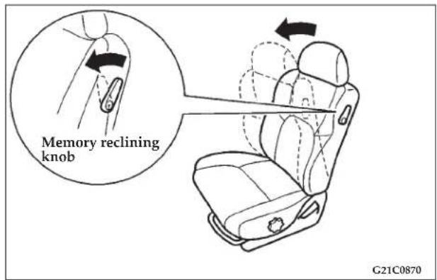
Pull the memory reclining knob and fold the seatback down.
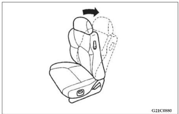
natural_image
Line drawing of a car seat assembly with an arrow indicating rotation (no text or symbols)Just by pushing the seatback up into position will lock it in the memorized position.
60 SEATS, SEAT BELTS, CHILD RESTRAINTS AND AIR BAGS
WARNING!
To minimize risk of severe or fatal personal injury in the event of a collision or sudden stop, both the driver and passenger seatbacks should always remain in a nearly upright position while the vehicle is in motion.
The protection provided by the seat belts will be reduced significantly the more the seatback is reclined.
There is greater risk that the seat belts will not be properly positioned on your body and/or you will slide under the belt in an accident the more the seatback is reclined, resulting in severe or fatal injury.
CAUTION!
Pull the seatback lock lever, and the seatback will return to its original position. When operating the lever, sit close to the seatback or check with your hand on it.
To adjust seat height (Driver's side only)
Type 1 (Manual)
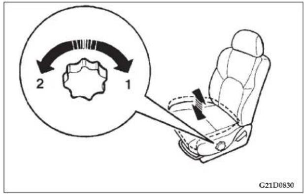
Turn the knob to raise or lower the whole seat cushion.
- Raise
- Lower
SEATS, SEAT BELTS, CHILD RESTRAINTS AND AIR BAGS 61
Type 2 (Power, driver's side only-if so equipped)
Front and/or rear parts of the seat cushion height can be adjusted.
Front part of the seat cushion
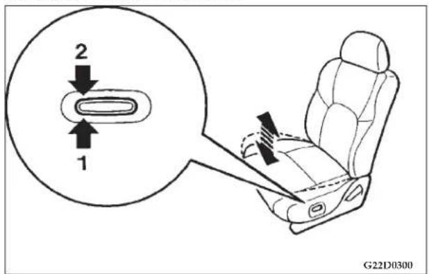
Push the switch to raise or lower the front part of the seat cushion.
- Raise
- Lower
62 SEATS, SEAT BELTS, CHILD RESTRAINTS AND AIR BAGS
Rear part of the seat cushion
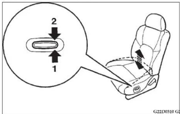
Push the switch to raise or lower the rear part of the seat cushion.
- Raise
- Lower
Whole seat cushion
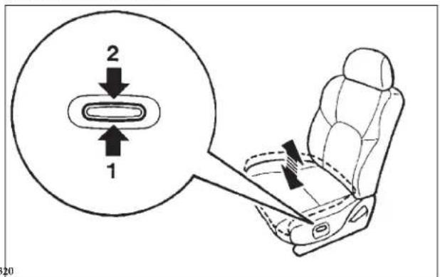
Push the center of the switch to raise or lower the whole seat cushion.
- Raise
- Lower
To adjust lumbar support (Driver's side only, if so equipped)
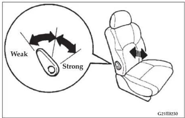
A lumbar support is included in the seatback of the driver's seat. The support has a three position adjustment.
SEATS, SEAT BELTS, CHILD RESTRAINTS AND AIR BAGS 63
For access to the rear seat (passenger side entry)
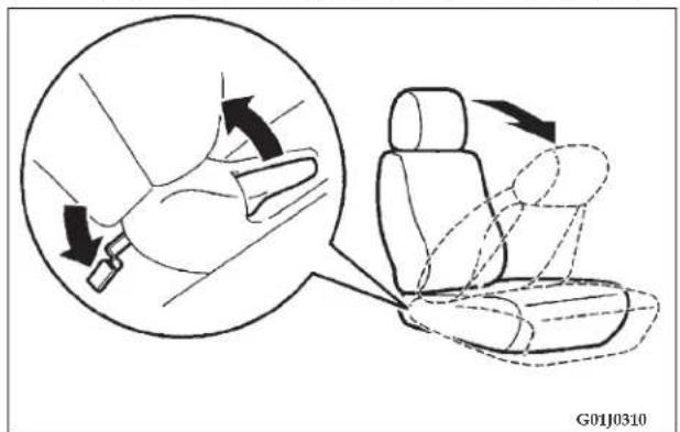
To permit rear seat entry or exit, the front seatback will fold down and the seat will move forward when the seatback lock lever is pulled up or when the pedal in back of the front passenger seat is depressed.
To return the seat, push the seatback backward until there is a "click" and the seat locks in position.
NOTE: The driver's side seatback will fold down only.
64 SEATS, SEAT BELTS, CHILD RESTRAINTS AND AIR BAGS
REAR SEATS
Rear seat capacity
WARNING!
- The rear seating capacity of this vehicle is three people.
- The rear seat occupants should always wear their seat belts when the vehicle is in motion.
Fold down rear seatbacks
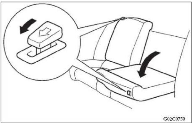
The rear seatbacks can be folded forward to provide additional cargo area.
Pull the left and/or right release knobs, and fold the rear seatbacks forward.
HEAD RESTRAINTS
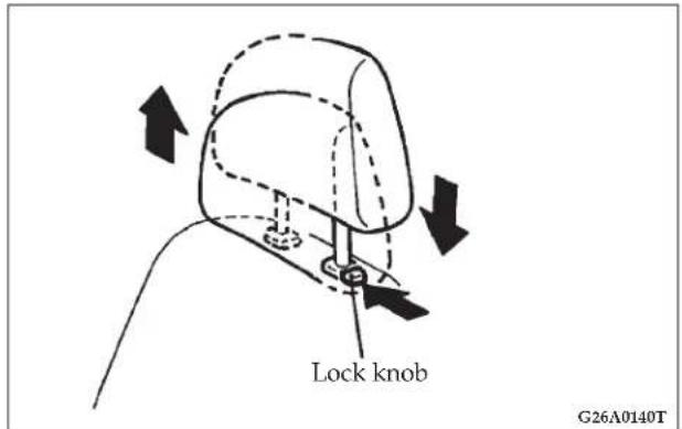
Padded head restraints for the front seats reduce the risk of whiplash injury in the event of a rear impact.
Adjustment of the head restraints
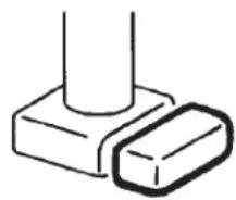
Adjust the head restraint height so that the center of the restraint is as close as possible to your seated eye level. Any person too tall for the restraint to reach their seated eye level, should adjust the restraint as high as possible.
- To raise the restraint, push in the lock knob and pull it straight up.
- To lower the restraint, push down on it while pressing the lock knob in the direction indicated by the arrow.
• After adjusting the height, lift up to confirm that it is locked in position.
WARNING!
- Failure to have head restraints properly mounted and adjusted may increase the chance of injury in the event of a collision.
- A cushion or similar device should not be placed on the seatback as it may increase the distance between your head and the head restraint and reduce the effectiveness of the restraint.
natural_image
Simple line drawing of a cylindrical object with a separate rectangular block, no text or symbols present.
natural_image
Black circular prohibition symbol on white background (no text or numbers)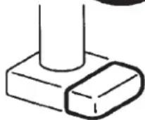
G26B0210
WARNING!
Driving with the head restraints removed can lead to serious injury to you and your passengers in an accident. Always have them mounted and properly adjusted before operating the vehicle. Failure to do so may increase the chance of injury in a collision.
SEAT BELTS
Seat belts are installed in your vehicle for the protection of the driver and passengers.
Always use the seat belts. In an accident, injury to the driver and passengers may be reduced if the seat belts are properly used.
NOTE: Legislation in your state may require seat belt usage; however, even if it is not required seat belts should always be used.
WARNING!
- Lock all doors before driving to reduce the risk of injury or ejection in a collision.
- Seat belts should always be worn by every adult who drives or rides in this vehicle, and by all children who are large enough to wear seat belts properly.
- Never use one seat belt for more than one occupant.
- Never carry more people in the vehicle than there are seat belts.
• Always adjust the belt for a snug fit. - Always route the shoulder belt over your shoulder and across your chest. Never put it behind you or under your arm.
- Always wear the lap belt as low as possible across your hips, not around your waist.
- To reduce the risk of serious or fatal injury in a collision, including from a deploying driver air bag, the driver should adjust the driver's seat to the rear most position that still allows good visibility and good control of the steering wheel, the brake, accelerator, and vehicle controls.
WARNING!
- To reduce the risk of severe or fatal injury from a deploying passenger air bag, make sure the passenger is also properly wearing their seat belt, remains sitting well back and upright in their seat and the seat is moved as far back as possible. Refer to "Supplemental Restraint System (SRS) - air bag" on page 87.
- Never hold an infant or child in your arms or on your lap when riding in a vehicle even if you are wearing your seat belt. Also never place any part of the seat belt you are wearing around an infant or child. To do so risks severe or fatal injury to your child in a collision or sudden stop.
- All children 12 years old and under should always ride in the rear seat, properly restrained, in order to reduce risk of serious or fatal injury in a collision, including from the deployment of a front passenger air bag. Refer to "Child restraints" on page 74.
WARNING!
- Any child who is too small to properly wear a seat belt must be properly restrained in an appropriate child restraint system. To reduce the risk of severe or fatal injury in a collision, including from the deployment of a front passenger air bag, children should be seated only in the rear seat. Infants must be in a rear-facing child safety seat and be seated only in the rear seat.
UNIBELT restraint system
All seats are equipped with a UNIBELT system which uses a single combined lap-and-shoulder belt with an emergency locking retractor.
This system is designed to provide comfort and safety by permitting full extension and automatic retraction of the belts during normal vehicle operation. A sensing device inside the belt retractor is designed to lock the retractor in the event of an abrupt change in vehicle motion.
NOTE: For instruction on how to install a child restraint system, see "Installing a child restraint system with a UNIBELT" on page 80.
68 SEATS, SEAT BELTS, CHILD RESTRAINTS AND AIR BAGS
UNIBELT instructions
natural_image
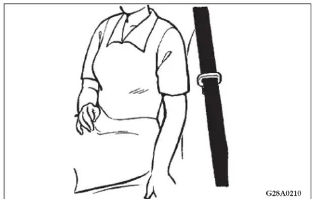
Line drawing of a person in a short-sleeve shirt holding a belt, no text or symbols present- Get in the vehicle and sit in a normal correct posture. To reduce the risk of severe or fatal injury caused by an inflating air bag, adjust the driver's seat to the rear most position that still allows you to fully apply the pedals, easily control the steering wheel and safely operate the vehicle. The front passenger should also adjust their seat as far back as possible. Refer to "Supplemental Restraint System (SRS) - air bag" on page 87.
All vehicle occupant's should sit and remain seated all the way back in their seat with their back resting straight against the upright seat back.
WARNING!
To minimize the risk of personal injury in the event of a collision or sudden stop, both the driver and passenger seatbacks should always be in a nearly upright position while the vehicle is in motion. The protection provided by the seat belts may be reduced significantly when the seatback is reclined. There is greater risk that the driver or the passenger will slide under the belt and be seriously injured when the seatback is reclined.
SEATS, SEAT BELTS, CHILD RESTRAINTS AND AIR BAGS 69
natural_image
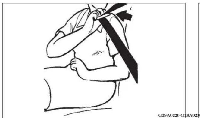
Line drawing of a person holding a long object, possibly a tool or device, with no visible text or symbols.- Grasp the metal tongue and slide it up the webbing so that it becomes easy to pull across your body. After a couple of tries this will become an automatic one-handed motion.
natural_image
Line drawing of a person sitting on a bench with a belt, no text or symbols present- Pull the seat belt out slowly while holding the metal tongue. This system will not lock up if you stop or hesitate, so relax and continue to "buckle-up". Push the metal tongue into the buckle until a "click" is heard. Pull up on the belt to confirm the metal tongue is locked securely in the buckle.
NOTE: If the seat belt is pulled to its full extension, it can enter the ALR mode and lock in position. If this occurs, allow the belt to fully retract and then repeat step 3.
70 SEATS, SEAT BELTS, CHILD RESTRAINTS AND AIR BAGS
natural_image
Illustration of a person using a seatbelt to lift the seat (no text or symbols)- Pull up on the shoulder portion of the belt to ensure that there is no slack in the lap belt. The belt will retain the small amount of slack necessary for comfort when you return to your normal seating position. If the belt is still too tight, pull out 6 to 8 inches of webbing, release the belt, and let it return to your chest.
NOTE: If a person wearing the seat belt moves their upper body or the belt completely unwinds, the retractor may switch to its Automatic Locking Retractor (ALR) child restraint installation mode and lock (see page 80), thus preventing further movement. If this happens, the person should switch the retractor back to its Emergency Locking Retractor (ELR) mode by unlatching the buckle and letting the belt fully retract. The person should then put the seat belt back on repeating steps 1 through 4.
WARNING!
- Be sure the lap belt portion fits snugly and as low as possible across the hips, not around the waist. Failure to do so may increase the chance or severity of injury in the event of a collision.
- Wear the seat belt without twisting it.
natural_image
Illustration of a person adjusting a seatbelt, showing hand positioning and force arrows (no text or symbols)- The shoulder belt portion will allow regular movement under normal conditions. The belt will lock in the event of an abrupt change in vehicle motion.
- To release the belt, push the button on the buckle. The belt retracts automatically, so hold the tongue when the belt is released and while it retracts. Should the belt not fully return to its stowed position, pull the shoulder belt down slightly and release quickly.
SEATS, SEAT BELTS, CHILD RESTRAINTS AND AIR BAGS 71
Adjustable seat belt shoulder anchor (front seats)
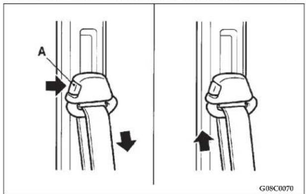
The seat belt shoulder anchor height can be adjusted for greater comfort.
To move the anchor down, depress the lock knob (A). To move the anchor up, simply slide the anchor up to the desired position (there is no need to depress the lock knob).
72 SEATS, SEAT BELTS, CHILD RESTRAINTS AND AIR BAGS
WARNING!
To reduce risk of serious injury in a collision, adjust the anchor at a position so that the belt passes over your shoulder, but does not touch your neck.
Always adjust the anchor when vehicle is not in motion.
Make sure the anchor is securely latched after adjustment.
Enhanced Driver Seat Belt Use Reminder System (BeltAlert™)
If the driver's seat belt has not been buckled within 60 seconds of starting the vehicle and if the vehicle speed is greater than 5mph (8 km/h), the Enhanced Warning System (BeltAlertTM) will alert the driver to buckle their seat belt. The driver should also instruct all other occupants to buckle their seat belts. Once the warning is triggered, the Enhanced Warning System (BeltAlertTM) will continue to chime and flash the Seat Belt Warning Light for 96 seconds or until the driver's seat belt is buckled.
The Enhanced Warning System (BeltAlert™) will be reactivated if the driver's seat belt is unbuckled for more than 10 seconds and the vehicle speed is greater than 5 mph (8 km/h).
The Enhanced Warning System (BeltAlert™) can be enabled or disabled by your authorized dealer or by following these steps:
NOTE:
The following steps must occur within the first 60 seconds of the ignition switch being turned to the ON or START position. The manufacturer does not recommend deactivating the Enhanced Warning System (BeltAlertTM).
- Turn the ignition switch to the OFF position, and buckle the driver's seat belt.
- Turn the ignition key to the ACCESSORY/RUN position (engine does not need to be running), and wait for the Seat Belt Warning Light to turn off.
- Within 60 seconds of starting the vehicle, unbuckle and then re-buckle the driver's seat belt at least three times within 10 seconds, ending with the seat belt buckled.
SEATS, SEAT BELTS, CHILD RESTRAINTS AND AIR BAGS 73
- Turn the ignition key to the OFF position. A single chime will sound to signify that you have successfully completed the programming.
The Enhanced Warning System (BeltAlert™) can be reactivated by repeating this procedure.
NOTE: Although the Enhanced Warning System (BeltAlert™) has been deactivated, the Seat Belt Warning Light will continue to illuminate while the driver's seat belt remains unfastened.
Seat belt extender
natural_image
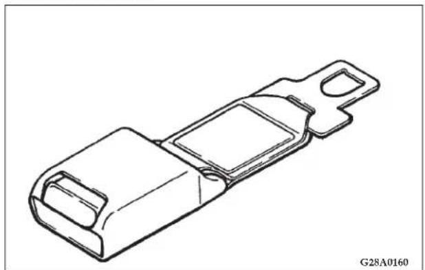
Technical line drawing of a mechanical component (no text or symbols)If the seat belt is too short, even when fully extended, a seat belt extender is available from your dealer. The extender may be used for either front seating positions.
©
WARNING!
- All children 12 years old and under should be seated in the rear seat, and properly restrained. Accident statistics indicate that children of all sizes and ages are safer when properly restrained in the rear seat rather than in the front seat.
- Any child who is too large to use a child restraint should ride in the rear seat and wear the lap and shoulder belt properly. The shoulder belt should be over the shoulder and across the chest, not across the neck, and the lap belt should be low on the child's hips, not across the stomach. If necessary, a booster seat should be used for proper seat belt fit; follow the booster seat manufacturer's instructions. Only use a booster seat that certifies it complies with Federal Motor Vehicle Safety Standards.
G28A0890
WARNING!
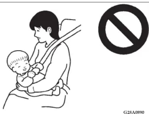
Never hold an infant or child in your arms or on your lap when riding in a vehicle, even if you are wearing your seat belt. Also never place any part of your seat belt around an infant or child. To do so risks severe or fatal injury to the child in a collision or sudden stop.
76 SEATS, SEAT BELTS, CHILD RESTRAINTS AND AIR BAGS
WARNING!
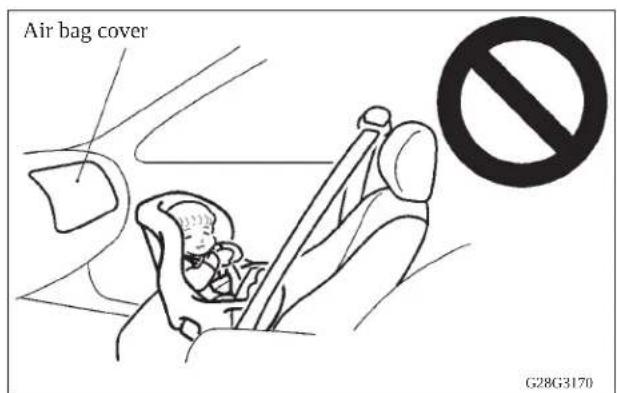
This vehicle is also equipped with a front passenger air bag. Rear facing child restraints place an infant too close to the air bag, the force of an inflating front passenger air bag could strike a rear-facing child restraint, causing serious or fatal injury to the child: REAR-FACING CHILD RESTRAINTS MUST ONLY BE USED IN THE REAR SEAT.
natural_image
Illustration of a child seated in a car seat with a belt and arrow indicating direction (no text or symbols)G28G1060
WARNING!
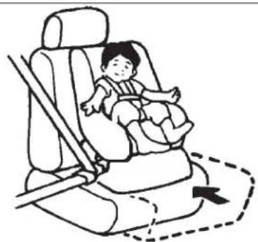
FRONT-FACING CHILD RESTRAINTS should always be used in the rear seat whenever possible; if one must be used in the front passenger seat, adjust the seat as far back as possible and ensure that the child stays in the child seat properly restrained. Failure to do so could kill or cause serious injury to the child.
WARNING!
- It is important to use an approved rear facing infant restraint until the infant is one year old to allow the infant's neck and spine to develop enough to support the weight of their head in the event of a collision.
- When installing a child restraint system, follow the instructions provided by the manufacturer and follow the directions in this manual. Failure to do so can result in severe or fatal injury to your child in a collision or sudden stop.
- After installation, push and pull the child restraint system back and forth, and side to side, to see that it is firmly secured. If the child restraint system is not installed securely, it may cause injury to the child or other occupants in the event of a collision or sudden stop.
- When not in use, keep your child restraint system secured with the seat belt or remove it from the vehicle in order to prevent it from being thrown inside the vehicle during an accident.
NOTE: Before purchasing a child restraint system, try installing it in the rear seat to ensure a good fit. Due to the location of the seat belt buckles and the shape of the seat cushion it may be difficult to securely install some child restraint systems.
If the child restraint system can be pulled forward or to either side easily on the seat cushion after the seat belt has been tightened, choose another child restraint system.
- Depending on the seating position in the vehicle and the child restraint system that you have, the child restraint can be attached using one of the following 2 methods:
- To the lower anchorage in the rear seat ONLY if the child restraint complies with Federal Motor Vehicle Safety Standard 213 (See page 78).
• To the UNIBELT (See page 80).
78 SEATS, SEAT BELTS, CHILD RESTRAINTS AND AIR BAGS
Installing a new child restraint system to the lower anchorage
natural_image
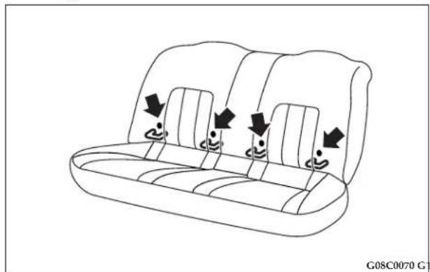
Line drawing of a car backseat with seatbelt and seatbelt covers, showing three seats with arrows indicating side indicators (no text or symbols)Your vehicle's rear seat is fitted with lower anchorages for attaching a new child restraint system that complies with Federal Motor Vehicle Safety Standard 213.
NOTE
- The marks on the seatback show the location of the lower anchorage points.
New child restraint system that complies with Federal Motor Vehicle Safety Standard 213
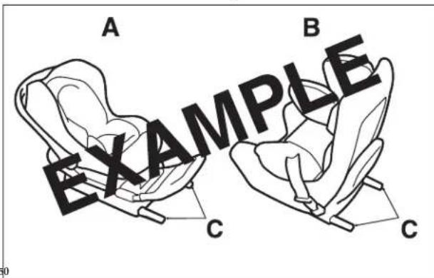
A: Rear-facing child restraint
B: Forward-facing child restraint
C: Child restraint system connectors (These are only examples.)
Installation
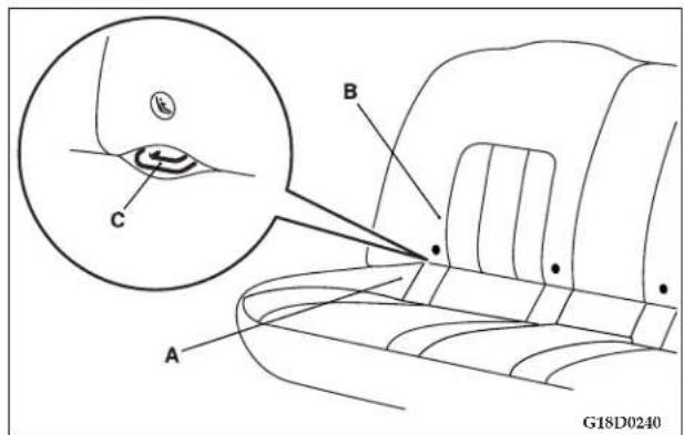
- Open the gap a little between the seat cushion (A) and the seatback (B) with your hand to locate the lower anchorages (C).
- Push the child restraint system's connectors into the lower anchorages (C) in accordance with the instructions provided by the child restraint system's manufacturer.
SEATS, SEAT BELTS, CHILD RESTRAINTS AND AIR BAGS 79
- If your child restraint system requires the use of a top tether strap, refer to "Tether anchors for child restraint systems" on page 83.
- Push and pull the child restraint system in all directions to be sure it is firmly secured.
NOTE:
- For a new child restraint system that complies with Federal Motor Vehicle Safety Standard 213, it is not necessary to secure the child restraint system using the vehicle's seat belt.
WARNING!
- If there is any foreign material in or around the connectors, remove it before installing the child restraint system. Also, make sure the seat belt is away from, not looped through or otherwise interferes with the child restraint system. If foreign matter is not removed and/or the seat belt interferes with the child restraint system, the child restraint system will not be secured properly and could move forward in the event of sudden braking or a collision, seriously injuring the child and possible other vehicle occupants.
- When the vehicle is moving, do not adjust the seat where the child restraint system is installed.
Installing a child restraint system to a UNIBELT at the rear seat positions or the front passenger seat (With emergency/automatic locking mechanism)
natural_image
Line drawing of a car climbing rope system with no text or symbolsG18C0790
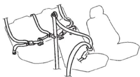
The UNIBELT at the rear seat positions, and at the front passenger seat, can be converted from normal Emergency Locking retractor (ELR) mode, to Automatic Locking Retractor (ALR) mode. It must be converted to the ALR mode when installing a child restraint system.
Children 12 years old and under should be restrained in the rear seat only, whenever possible, although the front passenger seat belt can also be the converted to ALR mode.
WARNING!
- Before placing an infant or child in a child restraint system, be absolutely certain you converted the retractor from the ELR mode to the ALR mode. The ALR mode will keep the child restraint system tightly secured to the seat.
Failure to convert the retractor to the ALR mode may allow the child restraint system to move forward during sudden braking or in a collision, seriously injuring the child or other occupants.
SEATS, SEAT BELTS, CHILD RESTRAINTS AND AIR BAGS 81
Installation:
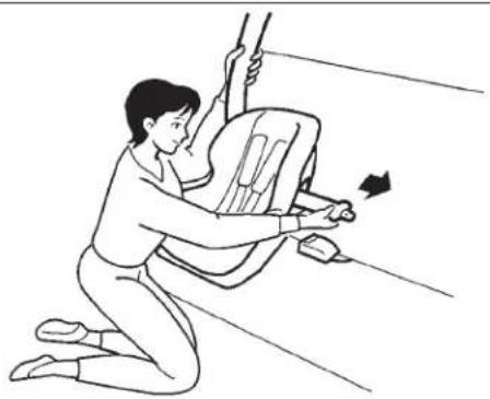
- Place the child restraint system in the rear seating position as shown in the illustration.
natural_image
Line drawing of a person kneeling in a seat using a tool to lift or press a seatbelt, with no text or symbols present.G18C0540
- Route the unibelt through the child restraint system according to the child restraint system manufacturer's instructions. Then insert the unibelt latch plate into the buckle. Make sure you hear a "click" when you insert the latch plate into the buckle.
82 SEATS, SEAT BELTS, CHILD RESTRAINTS AND AIR BAGS
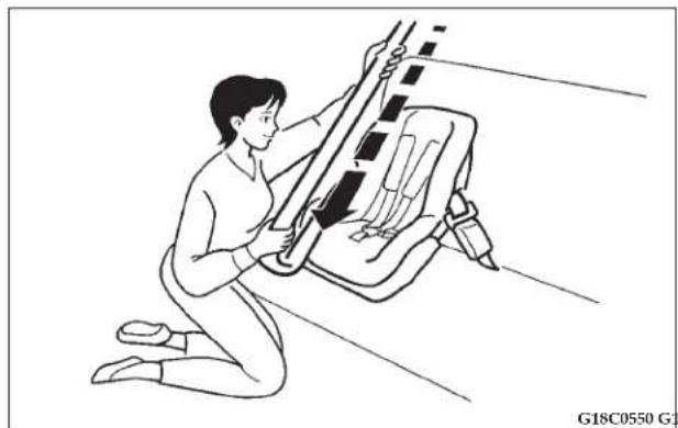
natural_image
Line drawing of a person kneeling to lift a car seat, no text or symbols present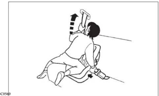
natural_image
Illustration of a person performing a physical maneuver with a tool and motion arrows (no text or symbols)- To activate the ALR mode, slowly pull the shoulder part of the belt all the way out until it stops, then let the belt feed back into the retractor.
-
After the belt has retracted, tug on it. If the belt is locked, you will not be able to pull it out. If you can pull the belt out, it is not locked and not in the ALR mode. You will need to repeat steps 3 and 4.
-
After confirming that the belt is locked, grab the shoulder part of the belt near the buckle and pull up to remove any slack from the lap part of the belt. Remember, if the lap part of the belt is not tight, the child restraint system will not be secure. It may help to put weight on the child restraint system and/or push on its seatback while pulling up on the belt (see illustration).
SEATS, SEAT BELTS, CHILD RESTRAINTS AND AIR BAGS 83
- If your child restraint system requires the use of a top tether strap, refer to "Anchors for the child restraint system" on page 83.
- Before putting the child in the restraint, push and pull the restraint in all directions to be sure it is firmly secure. Do this before each use. If the child restraint system is not firmly secure, repeat steps 1 through 6.
- To remove a child restraint system and deactivate the ALR mode, remove the child from the restraint. Unlatch the buckle, remove the belt from the restraint and let the belt fully retract.
Tether anchors for the child restraint system
natural_image
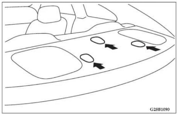
Top-down line drawing of a car interior showing dashboard, seats, and directional arrows (no text or symbols)In compliance with the Federal Motor Vehicle Safety Standards, your vehicle has 3 attachment points on the rear shelf, located behind the top of your rear seat. For securing a child seat tether strap to each of the 3 rear seating positions (2 outer and 1 center) in your vehicle.
84 SEATS, SEAT BELTS, CHILD RESTRAINTS AND AIR BAGS
Tether strap anchor installation
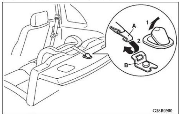
- Lift the cover from the tether anchor installation point by pulling it back with your hand as illustrated.
- Latch the top tether strap hook (A) of the child seat onto the tether anchor bracket (B) and tighten the top tether strap hook so it is securely fastened.
WARNING!
Child restraint tether anchorages are designed to withstand only those loads imposed by a correctly fitted child restraint system.
Under no circumstances are they to be used for adult seats, or harnesses, or for attaching other items or equipment to the vehicle.
Children who have outgrown child restraint systems
Children who have outgrown a child restraint system should be seated in the rear seat and wear the UNIBELT. If the shoulder belt crosses their face or neck, and/or the lap belt crosses their stomach, a commercially available booster seat must be used to raise the child so that the shoulder belt crosses their shoulder and the lap belt remains positioned low across their hips. The booster seat should fit the vehicle seat and should have a label certifying compliance with Federal Motor Vehicle Safety Standards.
WARNING!
- Children who are not buckled up, with all the doors locked, can be thrown out of the vehicle or otherwise be seriously or fatally injured in the event of a collision.
- A child should never be left unattended or unsupervised around the vehicle. When you leave the vehicle, always take the child out as well.
- Children can die from heat stroke if trapped inside vehicles, especially on hot days.
- Keep vehicles locked and trunks closed when not in use. Keep vehicle keys away from children.
SEATS, SEAT BELTS, CHILD RESTRAINTS AND AIR BAGS 85
Seat Belts And Pregnant Women
We recommend that pregnant women use the seat belts throughout their pregnancy. Keeping the mother safe is the best way to keep the baby safe.
Pregnant women should wear the lap part of the belt across the thighs and as snug across the hips as possible. Keep the belt low so that it does not come across the abdomen. That way the strong bones of the hips will take the force if there is a collision.
86 SEATS, SEAT BELTS, CHILD RESTRAINTS AND AIR BAGS
MAINTENANCE AND INSPECTION OF SEAT BELTS
The seat belt webbing may be cleaned with mild soap or detergent solution. Allow the belts to dry in the shade. Do not allow them to retract until completely dry. Do not attempt to bleach or re-dye belts. The color may rub off and webbing strength could be affected.
Regularly check seat belt buckles and release mechanisms for positive action and the retractors when in the automatic locking retractor mode for positive engagement. Refer to "Installing a child restraint system to a UNIBELT" on page 80.
Check that the anchor mounting bolts are tight. If the seat belt webbing shows obvious cuts, tears, protruding broken fibers that cause a local increase in webbing thickness, or severe fading which indicates weakening by exposure to sunlight, the entire seat belt assembly should be replaced.
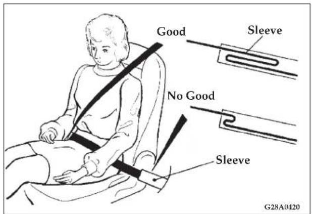
The lap belt portion of the front UNIBELT has a sleeve inside which the belt is folded back over itself in a loop. This allows the belt to help absorb the energy of a collision through a controlled release of the loop. In the event that the loop inside the sleeve has come loose, replace the entire seat belt assembly.
WARNING!
All seat belt assemblies, including retractors and attaching hardware, should be inspected by an authorized dealer after any collision. We recommend that all seat belt assemblies in use during a collision be replaced unless the collision was very minor and the belts show no damage and continue to operate properly.
Do not attempt to repair or replace any part of the seat belt assemblies; that work should be done by an authorized dealer. Failure to have an authorized dealer perform the work could reduce the effectiveness of the belts and could result in serious or fatal injury in a collision.
SEATS, SEAT BELTS, CHILD RESTRAINTS AND AIR BAGS 87
Supplemental Restraint System (SRS) - air bag
This vehicle is equipped with a Supplemental Restraint System (SRS), which includes air bags for the driver and front passenger. The SRS air bag is designed to supplement the primary protection of the driver and front passenger side seat belt systems by providing those occupants with protection against head and chest injuries in certain moderate to severe frontal collisions. The SRS side air bag (if so equipped) is also designed to supplement the seat belts and provide the driver and front passenger with protection against chest injuries in certain moderate to severe side impact collisions.
The SRS is NOT a substitute for the seat belts. For maximum protection in all types of crashes and accidents, seat belts must ALWAYS be worn by everyone who drives or rides in this vehicle (with infants and small children in an appropriate child restraint in the rear seat, and older children buckled in the rear seat). Refer to "Child Restraints" on page 74.
WARNING!
- IT IS VERY IMPORTANT TO ALWAYS WEAR YOUR SEAT BELT PROPERLY EVEN WITH AN AIR BAG.
- Seat belts help keep the driver and front passenger properly positioned. This reduces the risk of injury in all collisions, and reduces the risk of serious or fatal injuries when the air bags inflate. During sudden braking just before a collision, an unrestrained or improperly restrained driver or front passenger can move forward into direct contact with, or within close proximity to, the air bag when it begins to inflate. The beginning stage of air bag inflation is the most forceful and can cause serious or fatal injuries if the occupant comes in contact with the air bag at this time.
- Seat belts reduce the risk of injury in rollovers, side or rear impact collisions, and in lower-speed frontal collisions, because the air bags are not designed to inflate in those situations.
- Seat belts reduce the risk of being thrown from your vehicle in a collision or rollover.
WARNING!
- IT IS VERY IMPORTANT TO BE PROPERLY SEATED.
A driver or front passenger sitting too close to the steering wheel or instrument panel during air bag deployment can be killed or seriously injured
Air bags inflate very quickly and with great force. If the driver and front passenger are not properly seated and restrained, the air bag may not provide proper protection, and could cause serious or fatal injuries when it inflates.
- Before driving, adjust the driver's seat as far back as possible without affecting your ability to be in complete control of the vehicle.
- Before driving, adjust the front passenger seat as far back as possible.
- Make sure all vehicle occupants are always properly restrained using the available seat belts.
- With seat belts properly fastened, the driver and front passenger should sit well back in their seats and remain upright without leaning against the window or door.
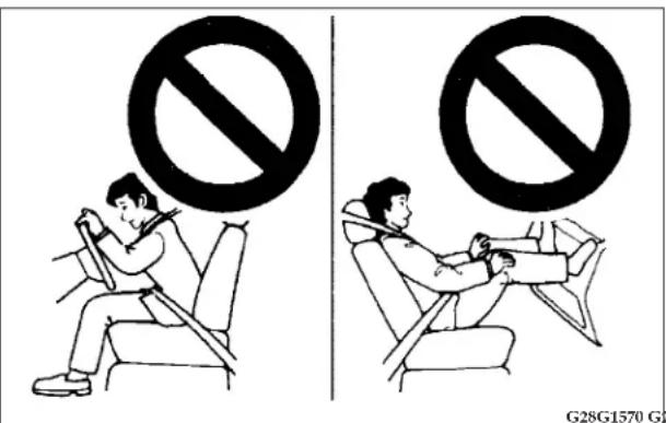
WARNING!
- Do not sit on the edge of the seat or lean your head or chest close to the steering wheel or instrument panel. Do not put your feet or legs on or against the instrument panel.
- Seat all infants and children 12 years of age and under in the rear seat properly restrained using an appropriate child restraint system.
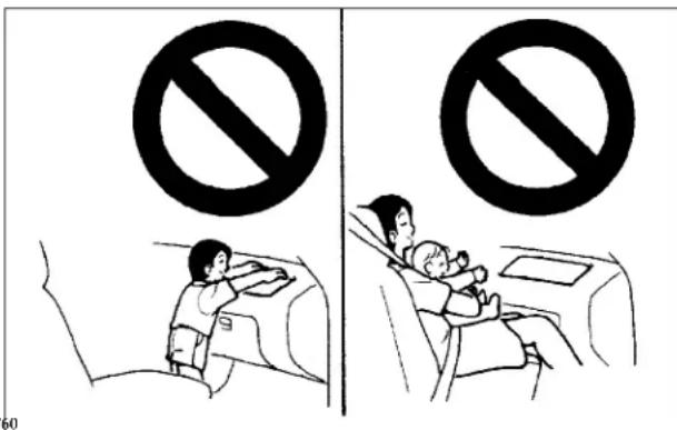
WARNING!
- Infants and small children should never ride unrestrained, or lean against the instrument panel. They should never ride held in your arms or on your lap. They could be seriously injured or killed in a collision, especially when the air bag inflates. Children should be properly seated in the rear seat in an appropriate child restraint system. Refer to “Child Restraints” on page 74.
90 SEATS, SEAT BELTS, CHILD RESTRAINTS AND AIR BAGS
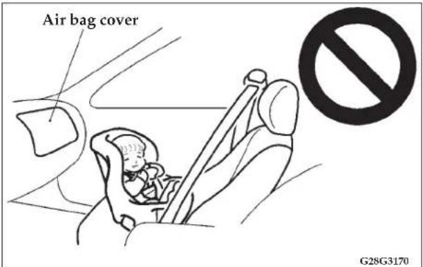
WARNING!
- REAR- FACING CHILD RESTRAINTS must NOT be used in the front passenger seat as it places an infant too close to the passenger air bag. The force of an inflating air bag could kill or cause serious injuries to the child. Rear-facing child restraints must only be used in the rear seat.
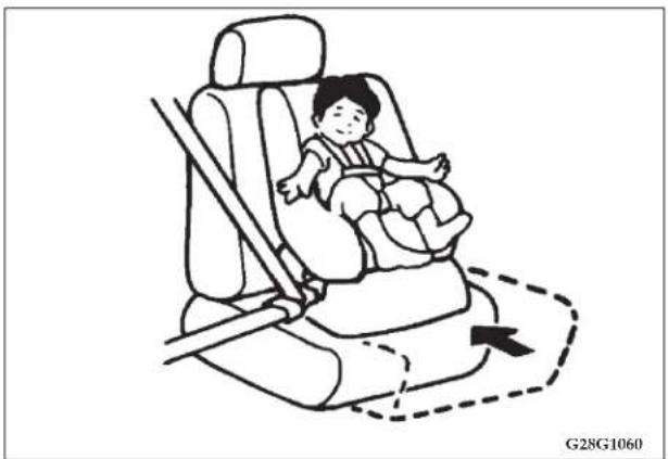
natural_image
Illustration of a child seated in a car seat with a dashed arrow indicating the seat area (no text or symbols)WARNING!
- FRONT- FACING CHILD RESTRAINTS should be used in the rear seat whenever possible. If they must be used in the front passenger seat, move the seat to the full rear position. Failure to do so could kill or cause serious injuries to the child.
- Older children up to and including 12 year olds, should be seated in the rear seat with their seat belt properly worn and with an appropriate booster seat if needed.
How the Supplemental Restraint System works The SRS includes the following components:
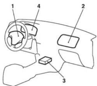
- Air bag module (Driver)
- Air bag module (Passenger)
- Air bag control unit (including the front impact sensors)
- SRS warning light
92 SEATS, SEAT BELTS, CHILD RESTRAINTS AND AIR BAGS
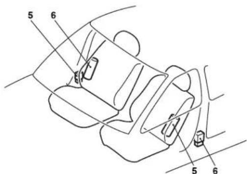
- Side air bag modules (if so equipped)
- Side impact sensors (if so equipped)
The air bag control unit monitors the readiness of the electronic parts of the system whenever the ignition switch is in the "ON" or "START" position. These include all of the items listed above and all related wiring.
The air bags will operate only when the ignition switch is in the "ON" or "START" position.
When an impact sensor detects a front or side impact of sufficient force, it automatically ignities materials in the module inflator which generate gas and inflates the appropriate air bags.
NOTE A collision that is not severe enough to need airbag protection will not activate the system. This does not mean something is wrong with the air bag system.
Deployment of the air bags produces a sudden, loud noise and releases some smoke and powder. This is not dangerous and does not indicate a fire in the vehicle. People with breathing problems may feel some temporary irritation from chemicals used to inflate the bags. If irritation continues see your doctor. You may open the windows after air bags inflates, if it is safe to do so.
After deployment, the air bags deflate very rapidly, so there is little danger of not being able to see. The time between the sensors first detecting an impact and the air bags deflating after deployment is shorter than a blink of an eye.
WARNING!
• Air bags inflate very quickly and with great force. In certain situations, contact with an inflating air bag may cause small cuts, abrasions, and bruises.
Driver's and passenger's front air bag system
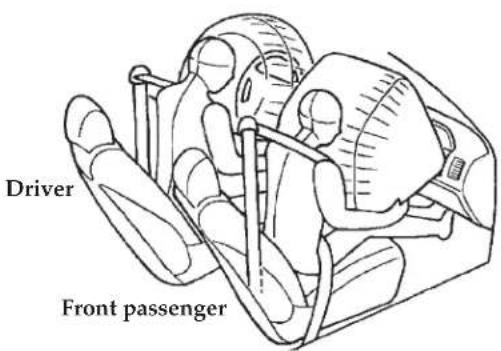
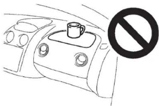
natural_image
Line drawing of a car interior with a coffee cup on the intake tray and a no-smoking symbol (no text or labels)WARNING!
- Do not attach anything to the steering wheel's padded cover, such as trim material, badges, etc. These could strike and injure an occupant if the air bag inflates.
WARNING!
- Do not set anything on, or attach anything to, the instrument panel above the glove compartment. Such items could strike and injure an occupant if the air bag inflates.
- Do not mount or locate any aftermarket equipment on or behind the knee bolsters.
- Do not attach accessories to, or put them in front of, the windshield. They could restrict the air bag inflation, or strike and injure an occupant, when the air bag inflates.
- Do not put packages, pets or other objects between the air bags and either the driver or the front passenger. This could affect air bag performance, or could cause severe or even fatal injury when the air bag inflates.
- Right after air bag inflation, several parts of the air bag system will be hot. Do not touch them. You could be burned.
- The air bag system is designed to work only once. After the air bags deploy, they will not work again. They must promptly be replaced and the entire air bag system inspected by an authorized dealer.
Side air bag system (if so equipped)
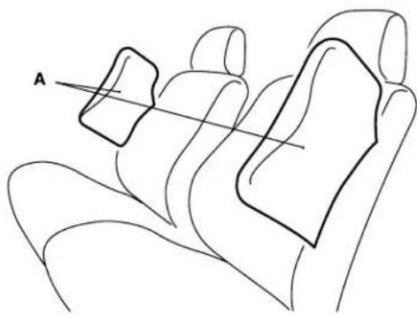
natural_image
Line drawing of a car interior with two rectangular objects labeled A, no text or symbols presentThe side air bags (A) are contained in the driver and front passenger seatbacks.
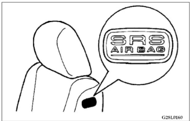
A label is attached to the seatbacks in vehicles with side air bags.
The side air bag is designed to inflate only on the side of the vehicle that is hit.
Because the side air bags do not protect the occupants in all types of collisions, be sure to always wear your seat belts properly.
SEATS, SEAT BELTS, CHILD RESTRAINTS AND AIR BAGS 95
WARNING!
- The side air bags are designed to supplement the driver and front passenger seat belts in certain side impacts. Seat belts should always be worn properly, and the driver and front passenger should sit well back and upright in their seats without leaning against the window or door.
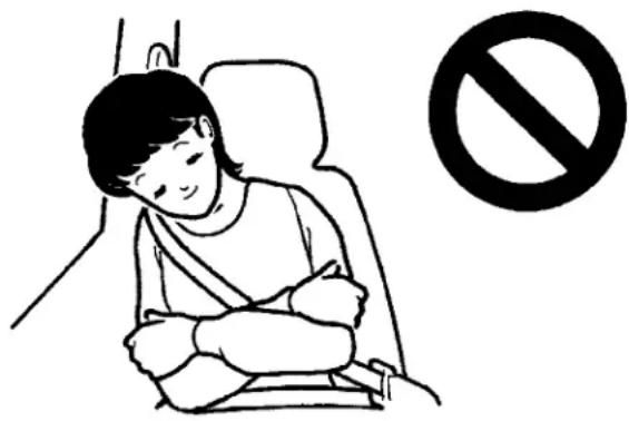
natural_image
Illustration of a person sleeping in a car seat with a no-smoking symbol nearby (no text or labels)WARNING!
- The side air bag inflates with great force. In order to reduce the risk of serious or possibly fatal injury when the air bag is inflating, the driver and front passenger should not put their arms out in the windows or lean against the doors.
WARNING!
- In order to reduce risk of injury from a deploying side air bag, do not allow any rear seat passengers to hold onto the back of either front seat. Special care should be taken with children.
- Do not place any objects near or around the front of either front seatback. Such objects could interfere with proper side air bag inflation, and could also cause injury if thrown by the deployment of the side air bag.
- Do not place stickers, labels or additional trim on the back of either front seat. It could interfere with proper side air bag inflation.
- Do not install seat covers on seats with side air bags. Do not re-cover the seats that have side air bags. Covers could interfere with proper side air bag inflation.
WARNING!
- Never install a rear-facing child restraint in the front passenger seat. Rear-facing child restraints MUST ONLY be used in the rear seat. Forward-facing child restraints should also be used in the rear seat. If a forward-facing child restraint must be used in the front passenger seat, move the seat as far back as possible, and make sure that the child stays in the child restraint and away from the door.
Do not allow the child to lean against or close to the passenger door even if the child is seated in a child restraint system. The child's head should also not lean against or be close to the section of the seatback where the side air bag is located. It is dangerous if the side air bag inflates. Failure to follow all of these instructions could lead to serious or fatal injury to the child. - Work done around and on the side air bag system components should only be done by an authorized dealer. Improper work methods could cause an accidental side air bag deployment, or could make a side air bag inoperable. Either of these situations could result in serious injury. Be sure to tell anyone who works on your vehicle that it has air bags.
SRS warning light
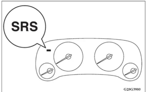
There is a Supplemental Restraint System (SRS) warning light on the instrument panel. The system checks itself each time the ignition is turned on and the light indicates if there is a problem.
When the ignition key is turned to the "ON" or "START" position, the warning light should come on for several seconds and then go out. This means the system is
working properly. The SRS warning light is shared by the driver's air bag, the front passenger's air bag, and the optional side air bags.
The air bags will operate only when the ignition switch is in the "ON" or "START" position
WARNING!
- If any of the following conditions occur, the SRS is not working properly and you should immediately have it inspected by an authorized dealer;
- The SRS warning light does not illuminate when you start the vehicle.
- The SRS warning light does not go out after several seconds.
- The SRS warning light comes on while driving.
SRS servicing
The entire SRS must be inspected by an authorized dealer 10 years after the vehicle's manufacture date as shown on the certification label located on the center pillar of the vehicle, on the driver's side.
WARNING!
- Any maintenance performed on or near the components of the SRS should be performed only by an authorized dealer. Do not permit anyone else to do service, inspection, maintenance or repair on any SRS components or wiring. Similarly, no part of the SRS should ever be handled, removed or disposed of by anyone except at an authorized dealer.
Improper work on the SRS components or wiring could result in an accidental air bag deployment or could make the SRS inoperative. Either of these situation could result in serious injury. - Do not modify your steering wheel or any other SRS components or related vehicle part. For example, replacement of the steering wheel, or modifications to the front bumper or body structure can negatively affect SRS performance and may lead to possible injury.
- If your vehicle has received any front-end damage, you should have the SRS inspected by an authorized dealer to make sure it is in proper working order.
WARNING!
- On vehicles with side air bags, do not modify your front seats, center pillar or center console. Such modifications can adversely affect SRS performance and may lead to possible injury.
Also, if you discover any tear or open seam in the seat fabric near the side air bag, have the seat inspected by an authorized dealer. - On vehicles with side air bags, if your vehicle has received any damage on either side, you should have the SRS inspected by an authorized dealer to make sure it is in proper working order.
NOTE:
- When you transfer ownership of the vehicle to another person, we urge you to alert the new owner that it is equipped with the SRS and refer that owner to the applicable sections in this owner's manual.
SEATS, SEAT BELTS, CHILD RESTRAINTS AND AIR BAGS 99
- If you decide to junk or scrap your vehicle, we urge you to first take it to an authorized dealer so that the SRS can be made safe for disposal.
Caution label
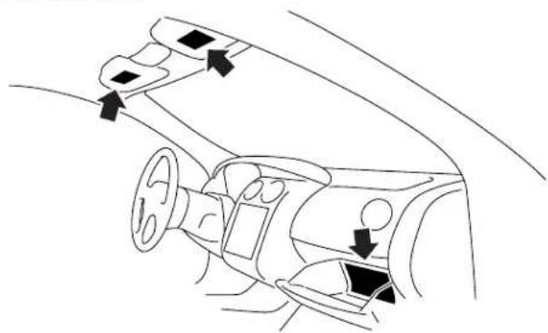
natural_image
Diagram of a car interior showing dashboard, steering wheel, and directional arrows indicating movement (no text or symbols)Passenger restraint warning/caution labels for the SRS are located in the vehicle as shown in the illustration.
100 SEATS, SEAT BELTS, CHILD RESTRAINTS AND AIR BAGS
Transporting Pets
Airbags deploying in the front seat could harm your pet. An unrestrained pet will be thrown about and possibly injured, or injure a passenger during panic braking or in a collision.
Pets should be restrained in the rear seat in pet harnesses or pet carriers that are secured by seat belts.
INSTRUMENTS AND CONTROLS
CONTENTS
■ Instrument cluster ..... 1 0 4
□ Meter cluster....104
□ Indicator and warning light package ..... 1 0 5
□ Speedometer....106
□ Tachometer....106
□ Fuel gauge....107
□ Odometer/Trip odometer....108
□ Engine coolant temperature gauge. . . . . . . . . 1 0 9
□ Turn signal indicators/hazard warning lights .. 110
□ High beam indicator....1 1 0
□Theft-alarm indicator....1 1 0
□ Door-ajar warning light and chime ..... 1 1 0
□ Anti-lock braking system warning light (if so equipped)....1 1 1
□ Cruise/speed control indicator ..... 1 1 1
□ Low-fuel warning light and chime....111
□ Front fog light indicator ..... 1 1 2
□ Charging system warning light .....112
□Oil pressure warning light . . . . . . . . . . . . . . . . . . . . . 112
□ Malfunction indicator light (SERVICE ENGINE SOON)....1 1 3
□ Supplemental Restraint System (SRS)-air bag warning light. 1 1 4
□ Brake warning light ..... 1 1 5
□ Seat belt reminder/warning light. . . . . . . . . . . 116
INSTRUMENTS AND CONTROLS
□ Changing the setting for warning operation ... 116
□ Automatic transaxle indicator
(if so equipped)....1 1 7
□ Traction Control System warning light (if so equipped) 1 1 7
□ Washer fluid level indicator ..... 1 1 7
■ Combination headlights, dimmer and turn signal lever 118
□ Headlights....1 1 8
□ Light auto-cutout feature
(headlights, fog lights, etc.) ..... 1 1 8
□ When you want to keep the lights on (time delay). 1 1 8
□ Headlight reminder chime ..... 1 1 9
□ Headlight flasher (high/low beam) ..... 1 1 9
□ Dimmer (high/low beam change) ..... 1 2 0
□ Turn signals. 120
■ Fog light switch....1 2 1
■ Hazard warning flasher switch ..... 1 2 2
■ Instrument panel light dimmer control ..... 1 2 3
■ Electric rear window defroster ..... 1 2 3
■ Windshield wipers....1 2 4
■ Intermittent wipers .... 1 2 5
■ Windshield washer .... 1 2 6
■ Precautions to observe when using wipers and washers 126
■ Dome light 127
■ Lights (dome lights, etc.) auto-cutout function 128
■ Reading lights....129
■ Rear personal lights....130
■ Horn switch 130
■ Garage door opener (if so equipped) ..... 1 3 0
□ Training the Universal Transceiver....131
INSTRUMENTS AND CONTROLS 103
□ Canadian Programming/Gate Programming. . .133
□Reprogramming a Signal Button....134
□ Operation....1 3 4
104 INSTRUMENTS AND CONTROLS
INSTRUMENT CLUSTER
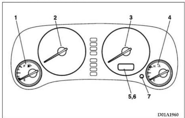
- Trip odometer
- Trip odometer reset button
Meter cluster
- Fuel gauge
- Tachometer
- Speedometer
- Engine coolant temperature gauge
- Odometer
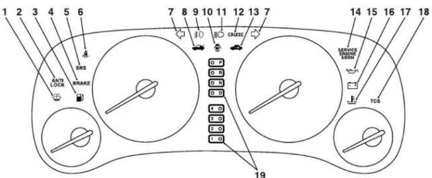
Indicator and warning light package
- Washer fluid level indicator → P.117
- Anti-lock braking system warning light (if so equipped) → P. 111
- Low-fuel warning light → P.111
-
Brake warning light → P.115
-
Supplemental Restraint System (SRS) - air bag warning light → P.114
- Seat belt reminder/warning light →P.116
- Turn signal indicators/hazard warning light → P. 110
- Trunk-ajar warning light → P 111
- Front fog light indicator (if so equipped) → P. 112
- Door-ajar warning light → P.110
106 INSTRUMENTS AND CONTROLS
- High beam indicator → P.110
- Cruise control indicator → P. 111
- Theft-alarm indicator (if so equipped) → P. 110
- Malfunction indicator light (SERVICE ENGINE SOON) → P.113
- Oil pressure warning light → P.112
- Charging system warning light → P.112
- Overheating warning light → P.114
- Traction control system warning light (if so equipped) → P.116
- Automatic transaxle indicator (Vehicles with Autostick automatic transaxle-if so equipped) → P.116
Speedometer
The speedometer indicates vehicle speed.
• The outer scale indicates miles per hour.
• The inner scale indicates kilometers per hour.
Tachometer
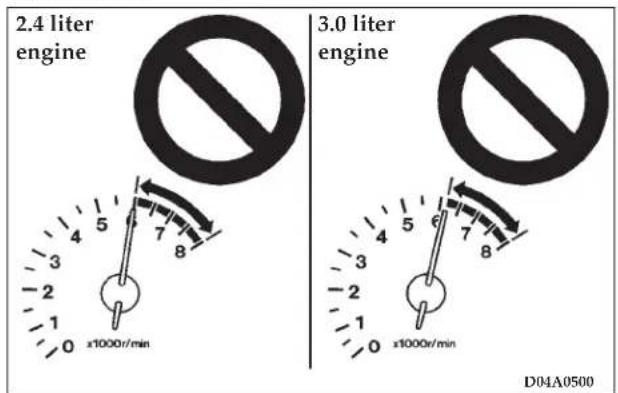
The tachometer indicates engine revolutions per minute. This allows the driver to determine the most efficient gear range and engine speed combinations.
CAUTION!
The red zone indicates an engine speed in excess of safe operation.
Select the correct gear to control engine speed so the tachometer indicator does not enter the red zone.
Fuel gauge
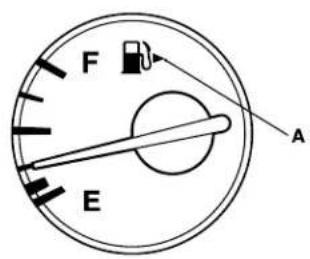
D05A0430
The gauge shows the amount of fuel in the fuel tank when the ignition key is turned to the "on" position. The arrow A indicates that the fuel lid (fuel filler port) is located on the right side of the vehicle. (Refer to "Fuel filler" on page 39.)
NOTE: Just after refueling, it takes a little time until the correct fuel level is indicated after turning on the ignition switch.
108 INSTRUMENTS AND CONTROLS
Odometer/Trip odometer
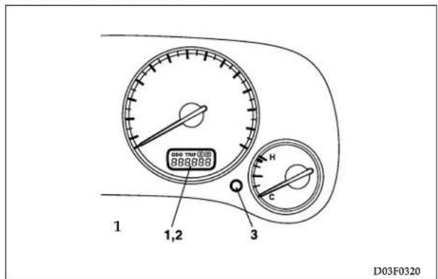
When the ignition switch is turned to the "ON" position, an "ODO" or "TRIP" indication is given.
Every time the reset button (3) is pressed lightly (less than one second), the indicators will change from "ODO" to "Trip A" to "Trip B".
- Odometer
- Trip odometer
3. Reset button
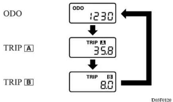
flowchart
graph TD
    A["ODO 123.0"] --> B["TRIP A 35.8"]
    B --> C["TRIP B 8.0"]
ODO --- Odometer
The odometer indicates the total distance the vehicle has travelled.
TRIP --- Trip odometer
The trip odometer indicates the distance traveled during a particular trip or period.
As a feature, there are two trip odometer displays:
A and. B
Trip [A] be used to measure the distance traveled since the current trip began and Trip [B] can be used to measure the distance from an intermediate location.
To return either Trip □ or Trip □ play to zero, press the reset button (3) for more than one second. Only the currently displayed value will be reset.
If Trip A is displayed, for example, only Trip W be reset.
NOTE
-
Display TRIP and TRIP each has a maximum distance of 9999.9 mile (16 093.28 km)
-
When disconnecting the battery for a long time, the memory of trip meter display A and clear, and the display returns to "0".
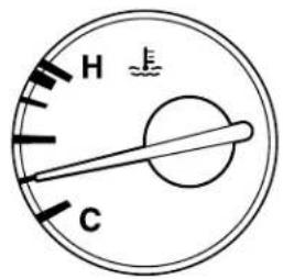
D06A0460
Engine coolant temperature gauge
This gauge indicates the engine coolant temperature. When the engine temperature is low, the indicator will remain at the "C" (cold) position. The indicator will gradually rise as the engine is warmed up. The indicator will normally stay near the center while driving, but may rise slightly in congested traffic or when the engine is under a heavy load.
110 INSTRUMENTS AND CONTROLS
CAUTION!
While driving, care should always be taken to maintain normal engine operating temperature. If the indicator enters the "H" (hot) position while driving, the engine is overheating. (Refer to "Engine overheating" on page 272.)
Turn signal indicators/hazard warning lights

The arrow will flash in unison with the corresponding exterior turn signals when the turn signal lever is operated.
Both arrows will flash intermittently when the hazard warning flasher switch is pressed.
NOTE: If the signal indicator blinks too fast, the cause may be a faulty turn-signal connection or faulty lamp bulb.
High beam indicator

A blue light illuminates when the head-lights are on high beam.
Theft-alarm indicator
When the theft-alarm system has been armed, the indicator located in the instrument cluster will illuminate and go off in 20
seconds, indicating the system is armed. (See "Theft-alarm system" on page 48.)
Door-ajar warning light and chime
This light illuminates when either door or the trunk is open or not completely closed. When the vehicle is moving at more than 5 mph (8 km/h) and the door is open or ajar, a chime will sound to inform the driver that
the door is not properly shut.
CAUTION!
Before driving, check to ensure that the door-ajar warning light is off.
Trunk-ajar warning light and chime
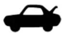
This light illuminates when the trunk lid is open or not completely closed.
When the vehicle is moving at more than 5 mph (8 km/h) and the trunk lid is open or
ajar, a chime will sound to inform the driver that the trunk lid is not properly shut.
Anti-lock braking system warning light (if so equipped)
ANTI LOCK
This light comes on in the event of a malfunction in the anti-lock braking system. Always be sure that the light goes out before beginning to drive.
It also comes on when the ignition key is turned to the "ON" position and should go out shortly after starting the engine.
If the light illuminates during driving;
- Stop the vehicle in a safe place and turn off the engine. Test the system by restarting the engine and driving at a speed of about 12 mph (20 km/h) or higher.
If the light goes out, there is no abnormal condition.
- If the light does not go out or if it illuminates again, the anti-lock braking system is not functioning, and only the standard braking system is functioning.
If this occurs, take your vehicle to an authorized dealer and have the system checked.
NOTE: If the light remains illuminated after the engine is started, it indicates that a fault has occurred in the Anti-lock brake system. The standard brake system will function normally. (Refer to "Anti-lock braking system" on page 169).
Cruise/speed control indicator
CRUISE
This indicator will illuminate when the cruise/speed control main switch is "ON".
Low-fuel warning light and chime
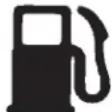
When the fuel level in the fuel tank gets low, the light illuminates and the chime will also sound. It is recommended that fuel be added as soon as this light illuminates.
112 INSTRUMENTS AND CONTROLS
CAUTION!
Do not drive with an extremely low fuel level; running out of fuel could cause damage to the catalytic converter.
Front fog light indicator
This indicator illuminates while the fog lights are on.
NOTE: Fog lights will not be operational when high beam (headlights) are selected.
Charging system warning light
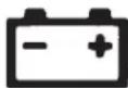
This light illuminates in the event of a malfunction in the charging system.
This light illuminates when the ignition key
is turned to the "ON" position (engine off). When the engine is started, the light should go off. Always be sure that the light goes out before beginning to drive.
CAUTION!
If the charging light remains on after the engine has started, the battery charging system may be malfunctioning. In this case, take your vehicle to an authorized dealer and have the system checked.
Oil pressure warning light
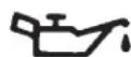
This light illuminates when the engine oil pressure is below normal. If the light stays
on while driving, stop the engine as soon as possible and do not drive until the cause of the low oil pressure is corrected.
CAUTION!
- If this light illuminates and the engine oil level is not low, have your vehicle checked at an authorized dealer.
- This warning light does not indicate the amount of oil in the crankcase. This must be determined by checking the oil level with the dipstick while the engine is turned off.
Malfunction indicator light (SERVICE ENGINE SOON)
SERVICE ENGINE SOON
This light is part of an onboard diagnostic (OBD) system which monitors the emissions, engine and automatic transaxle control systems. If a problem is detected in one
of these systems, this light may illuminate. Although your vehicle will usually be drivable and not need towing, have the system checked as soon as possible at an authorized dealer.
This light will also illuminate for a few seconds, when the ignition key is turned to the "ON" position. If it does not go off after a few seconds, take the vehicle to an authorized dealer.
CAUTION!
- Prolonged driving with the malfunction indicator light on may result in further damage to the emission control system. Continued driving could also affect fuel economy and driveability.
- If the light does not illuminate when the ignition key is turned to the "ON" position (bulb check), have the system checked at an authorized dealer.
NOTE: Do not disconnect the battery cable when the Malfunction indicator light (SERVICE ENGINE SOON) is ON.
The engine electronic control module stores critical OBD data, which may be lost if the battery is disconnected. This can make rapid diagnosis more difficult.
If the fuel tank filler cap is not secured properly, the light may come on. Be sure the fuel tank filler tube cap is tightened every time you add fuel. (Turn the fuel tank filler cap clockwise until you hear clicking sounds.)
Overheating warning light
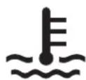
If the warning light illuminates while the engine is running, it is possible that the engine is overheated.
Immediately park your vehicle in a safe place and make the necessary corrections.
(Refer to "Engine overheating" on page 272.)
While driving, care should always be taken to maintain the normal operating temperature.
Supplemental Restraint System (SRS)-air bag warning light
SRS
This light illuminates when the Supplemental Restraint System-air bag is not working properly. It will also illuminate for about 7
seconds after the ignition key is turned to the "ON" position or after the engine is started. The light should then go out.
Check the light every time the vehicle is started.
If it does not illuminate, or stays on for more than approximately 7 seconds after the ignition key is turned "ON" or after the engine is started, or if it comes on while
driving, take your vehicle to your authorized dealer and have the system checked.
[See "Supplemental Restraint System (SRS)" on page 114.]
Brake warning light
BRAKE This light illuminates when the ignition key is turned to the "ON" position (engine off). When the engine is started, the light should go off. But when the parking brake is applied or the brake fluid falls below the prescribed level, the light illuminates. Before driving your vehicle, release the parking brake fully and make certain that the brake warning light has gone out.
CAUTION!
If the brake warning light does not go on when you pull the parking brake lever, or if it does not go out when you release the lever, contact an authorized dealer immediately.
If the brake warning light illuminates while driving, it could mean braking performance deterioration. Park your vehicle in a safe place using the following procedures:
-
If, when pressing the brake pedal, braking is poor, press your foot harder against the brake pedal.
-
Should the braking deteriorate, use engine braking by shifting the transaxle into a lower gear (Manual transaxle or Automatic transaxle autostick) or into the "3" (THIRD) or the "2" (SECOND) or the "L" (LOW) position (Automatic transaxle) to reduce the speed and slowly pull the parking brake lever, while applying pressure against the brake pedal.
Depress the brake pedal to turn on the stop light (brake light) to alert the vehicles behind you.
CAUTION!
Suddenly applying the parking brake is dangerous, the wheels may lock.
Seat belt reminder/warning light
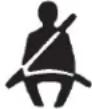
A chime and warning light are used to remind the driver to fasten the seat belt. When the ignition key is turned to the "ON" position, the warning light will illuminate and a chime will sound for about 6 seconds. If the driver's seat belt remains unfastened approximately 1 minute later, the warning light will flash and the chime sound intermittently (each 12 times) when the vehicle is driven. If the driver subsequently unfastens the seat belt while driving, the warning light and chime will issue further warnings. And if the seat belt remains unfastened, the warning light and chime will issue further warnings each time the vehicle starts moving. When the seat belt is fastened, the warnings will stop.
Changing the setting for warning operation
It is possible to disable the warning function so that warnings are not issued after the start of driving. (The function is initially enabled at the factory.)
-
Fasten the driver's seat belt.
-
Turn the ignition switch to the "ON" position.
-
With the seat belt still fastened, confirm that the warning light goes off.
- Within 1 minute of seeing the warning light go off, remove the plate from the buckle and re-insert it 3 times.
- Turn the ignition switch to the "LOCK" or "ACC" position. The buzzer (with a short tone) will sound once to indicate that the setting change is complete.
NOTE
- If the driver's door is open at this time, the buzzer (with long intermittent tones) will sound continuously but the setting change will not be completed. To complete the setting change, remove the key or close the driver's door. The buzzer (with a short tone) will sound once to indicate that the setting change is complete.
- If you wish to change the setting again, perform the same procedure again.
- If you do not understand how to change the setting, consult an authorized Mitsubishi dealer.
WARNING!
In order to reduce risk of serious or fatal injury in an accident, always wear your own seat belt, and do not allow anyone to ride in your vehicle unless he or she is properly seated and wearing a seat belt. Children should be properly seated and restrained in an appropriate child restraint system.
Automatic transaxle indicator (if so equipped)
When the ignition key is turned to the "ON" position, the indicator light illuminates to show the position of the selector lever. (i.e. "PARK", "DRIVE", "REVERSE", etc.)
Traction Control System warning light (if so equipped)
TCS
This light will illuminate in the event of a malfunction in the traction control system. It will also come on when the ignition key is
turned to the "ON" position and should go out after the engine starts. (See "Traction control system" on page 192)
Washer fluid level indicator

This light will illuminate and the chime will sound when the windshield washer level is low. (approximately 0.1 gal/0.4 L) When the light comes on, add fluid.
118 INSTRUMENTS AND CONTROLS
COMBINATION HEADLIGHTS, DIMMER AND TURN SIGNAL LEVER
Headlights
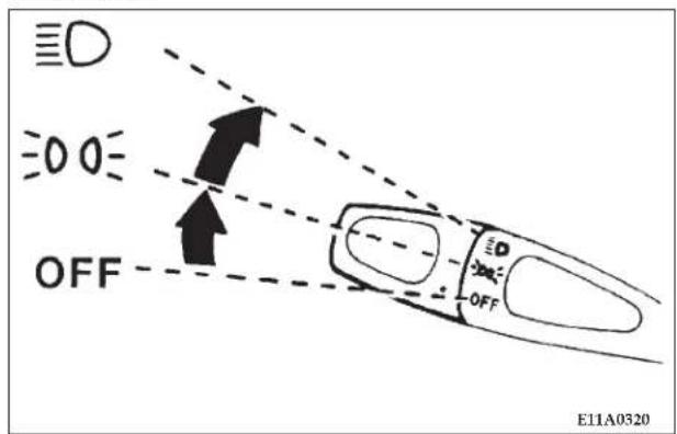
Rotate the switch to operate the lights.
OFF - All lights off
DO =
- Parking, tail, front and rear side marker, license plate and instrument panel lights on
3D
- Headlights and other lights on
NOTE: Do not leave the headlights and other lamps on for a long time while the engine is not running. A discharged battery could result.
Light auto-cutout feature (headlights, fog lights, etc.)
- This feature will help prevent a discharged battery. If the headlamps are left on "∅0" or "∅" when leaving the vehicle (ignition key removed, in "ACC" or "LOCK" position), the lights will stay on for approximately 10 minutes and then turn off.
- If the light switch is turned to ON " 00" or "D" again, the light auto-cutout will not function and the headlamps will stay on.
When you want to keep the lights on (time delay):
The lights can be made to stay on for about 60 seconds after the driver leaves the vehicle. This feature provides the safety of headlight illumination when leaving your vehicle in an unlighted area.
- Rotate the ignition key to "LOCK" or "ACC" position with the light switch in the ON "≡D" position.
- Turn light switch to "OFF" position within about 45 seconds of ignition key removal.
- The headlights will stay on for about 60 seconds, then automatically turn off.
Headlight reminder chime
If the driver's door is opened (ignition key in "LOCK", "ACC" or out of ignition cylinder) with the light switch in the ON "≡00≡" or "≡0" position, a chime will sound to remind the driver to turn off the lights. Turning off the light switch will stop the chime.
Headlight flasher (high/low beam)
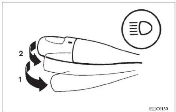
The headlights can be made to flash (high beam) when the lever is pulled slightly to (2), and will go back to normal when it is released. While the high beam is on, a blue light in the instrument cluster will also illuminate.
120 INSTRUMENTS AND CONTROLS
NOTE: The headlights can also flash when the light switch is OFF.
If you turn the lights off with the headlights set to high-beam illumination, the headlights are automatically returned to their low-beam setting when the light switch is next turned to the ON “≡D” position.
Dimmer (high/low beam change)
To change the headlights from high beam to low beam and vice versa, pull the turn signal lever to (1). Switch the headlights to low beam as a courtesy whenever there are oncoming vehicles, or when there is traffic moving ahead of you. An illuminated blue light in the instrument cluster indicates when the headlights are on high beam.
Turn signals
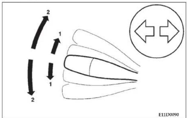
For changing lanes, or when making a gradual turn, the lever may be held in the "lane change" position (1). It will return to the neutral position when released. The fully engaged position (2) is for use when making a normal turn. The lever will return automatically upon completion of the turn.
There may be occasions when the lever does not return after cornering. This typically occurs when the steering wheel is turned only slightly. In this case, return the lever by hand.
The instrument cluster indicator will flash to indicate proper operation of the front and rear turn signal lights.
If the indicator light flashes faster than usual, check for a malfunctioning turn signal light bulb or faulty turn signal system.
If the indicator fails to light when the lever is moved, check for a faulty fuse or a burned out indicator bulb.
NOTE: Replace malfunctioning bulbs and fuses promptly.
FOG LIGHT SWITCH
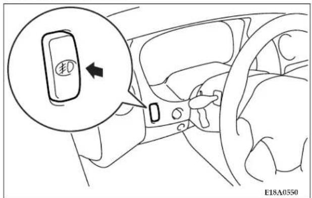
The fog lights illuminate only when the headlights are on. Press the switch to illuminate the fog lights and press the switch again to turn the lights off.
The indicator light in the instrument cluster will illuminate while the fog lights are on.
122 INSTRUMENTS AND CONTROLS
NOTE
- If the headlights are switched to high beam, the fog lights will go out; they will illuminate again when the headlights are switched back to low beam.
- If the light switch is rotated to OFF while the fog lights are illuminated, they will automatically turn off. They can be turned back on again by moving the light switch back to ON and pressing the fog light switch again.
HAZARD WARNING FLASHER SWITCH
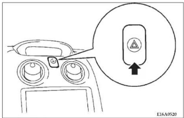
Press the flasher switch and the front and rear turn signals will flash intermittently, as the hazard warning lights. This is an emergency warning system and is not intended for use when the vehicle is in motion.
If it is necessary to leave the vehicle, the flasher system will continue to operate with the ignition key removed.
NOTE: If the lights are kept flashing for several hours, the battery will be discharged (rundown), resulting in hard engine starting or a no start condition.
INSTRUMENT PANEL LIGHT DIMMER CONTROL
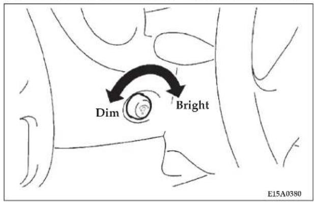
The brightness of the instrument panel lights can be adjusted by turning this knob while the light switch is in the ON "300" or "200" position.
ELECTRIC REAR WINDOW DEFROSTER
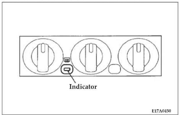
The electric rear window defogger can be operated when the ignition key is in the "ON" position.
When the switch is pressed, an indicator in the switch (amber) will illuminate to indicate the electric rear window defogger is on, and electric current will flow through the heating wire on the rear window to clear away fog or frost.
124 INSTRUMENTS AND CONTROLS
It will turn off automatically in about 17 minutes.
To turn off the defogger before 17 minutes has lapsed, push the switch again.
CAUTION!
- The rear window defroster is not designed to melt snow. Remove snow before use of the rear window defroster.
- Use the rear window defroster only after the engine has started and is running. Be sure to turn the defroster switch off immediately after the window is clear in order to prevent excessive battery discharge.
- Do not place stickers, tape or other items that are attached with adhesive over the grid wires on the rear window.
- When cleaning the inside rear window from inside, use a soft cloth and wipe lightly over the heating wires.
WINDSHIELD WIPERS
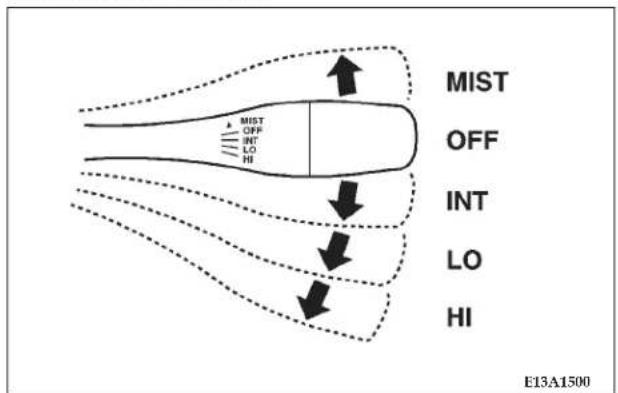
flowchart
graph TD
    A["MIST"] --> B["OFF"]
    B --> C["INT"]
    C --> D["LO"]
    D --> E["HI"]
    style A fill:#f9f,stroke:#333
    style B fill:#ccf,stroke:#333
    style C fill:#cfc,stroke:#333
    style D fill:#fcc,stroke:#333
    style E fill:#ffc,stroke:#333
The windshield wipers can be operated when the wiper lever is moved as illustrated above and the ignition key is in the "ON" or "ACC" position.
MIST = Misting function
The wipers will operate once
OFF = Off
INT = Speed sensitive
Interval between wipers varies in accordance with vehicle speed
The intermittent intervals are adjustable from approximately 3 to 18 seconds by rotating the adjusting knob at the end of the stalk.
LO = Slow
HI = Fast
INTERMITTENT WIPERS
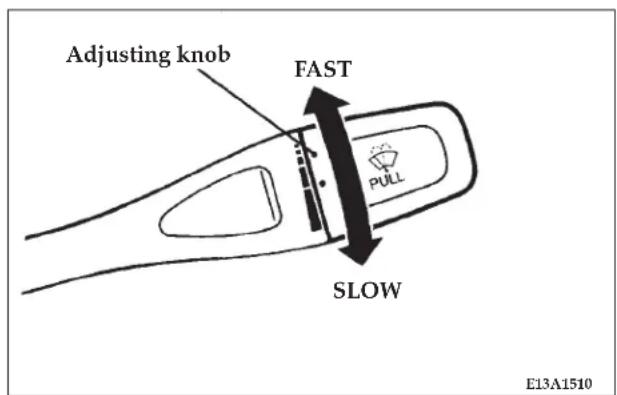
Use the intermittent feature when weather conditions make a single wiping cycle, with a pause between cycles, desirable.
For maximum delay between wipes, rotate the knob toward you. To shorten the delay, rotate the knob away from you.
The delay can be regulated between approximately 3 and 18 seconds.
NOTE: Vehicle speed is monitored and the delay will be shortened when the vehicle is moving above 10 mph (16 km/h) and lengthened when the vehicle is moving below 10 mph (16 km/h).
WINDSHIELD WASHER
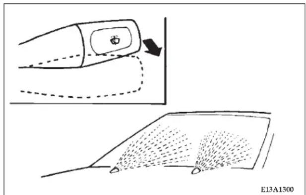
natural_image
Diagram showing a car interior with a hand pointing to a vehicle and its open roof, alongside a fan-shaped diagram illustrating airflow or movement (no text or symbols)The windshield washer can be operated by pulling the lever toward you to spray fluid when the ignition key is in either the "ON" or "ACC" position.
When washer fluid is sprayed, the wipers will automatically operate several times.
The spraying fluid stops when the lever is released.
PRECAUTIONS TO OBSERVE WHEN USING WIPERS AND WASHERS
CAUTION!
If the washer is used in cold weather, the washer fluid sprayed onto the glass might freeze, resulting in poor visibility. Heat the glass with the defroster before using the washer.
NOTE
- Do not use the wipers when the glass is dry; this could scratch the glass and wear the wiper blades prematurely.
- Before operating the wipers in cold weather, check to be sure that the wiper blades are not frozen to the windshield. Attempting to operate the wipers while the blades are frozen could damage the wiper motor.
- If the wipers become blocked by ice or other deposits on the glass, the motor may be damaged even if the wiper switch is OFF. If obstruction occurs, park your
vehicle in a safe place, turn off the ignition, and clean the deposits from the glass so that the wipers operate smoothly.
-
Avoid using the washer for more than 20 seconds at a time. To avoid pump damage, do not operate the washer when the fluid reservoir is empty.
-
During cold weather, be sure to add a washer solution that will not freeze in the washer reservoir. Failure to do so could result in the loss of windshield washer function and damage to the system components.
-
Replace wiper blades when they are worn to avoid loss of visibility when in use. Use the appropriate size replacement blades; if you have questions, ask your authorized dealer.
DOME LIGHT
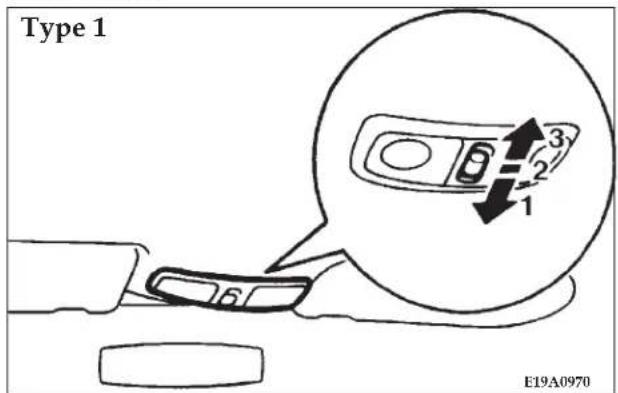
The dome/reading light can be operated by moving the switch as follows:
-
(ON) - The dome light "ON".
-
(DOOR) - The dome light goes on when any door is opened.
-
(OFF) - The dome light stays "OFF".
128 INSTRUMENTS AND CONTROLS
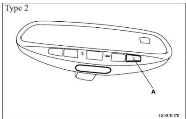
Push the light switch (A) to turn on the light, and push the light switch again to turn them off.
LIGHTS (DOME LIGHTS, ETC.) AUTO-CUTOUT FUNCTION
If any of the interior lights is left on with the ignition key in the "LOCK" position, the light goes off automatically after approximately 30 minutes to prevent the battery from running down.
The light comes on again if the ignition key is turned to the "ON" or "ACC" position (except "Dome Light" Type 2), or "ON" position ("Dome light" Type 2 only), any door is opened and closed, or the keyless entry system is operated.
READING LIGHTS
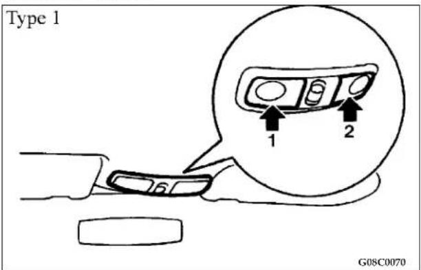
-
Driver's side
-
Passenger's side
Push the right or left reading light switch (lens) to turn on the light.
This light produces a spot beam for convenient use as a map light at night.
Push the reading light switch again to turn the light off.
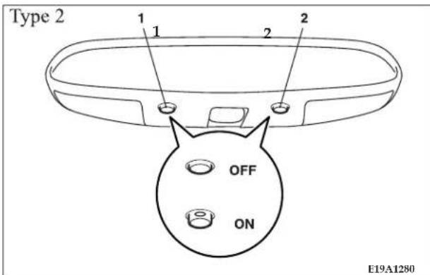
NOTE:
- If the reading lights are left on for prolonged periods of time with the engine turned off, the battery will be discharged (run down).
130 INSTRUMENTS AND CONTROLS
REAR PERSONAL LIGHTS
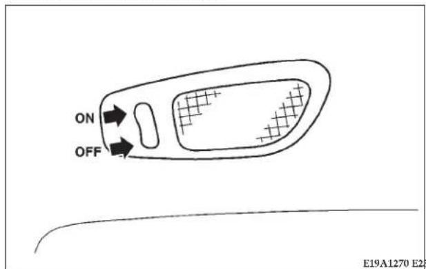
HORN SWITCH
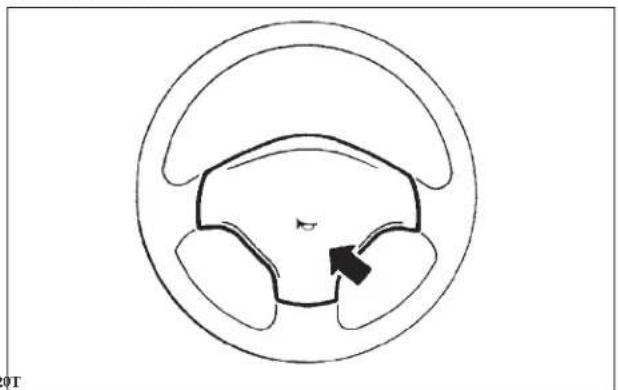
natural_image
Diagram of a biological structure with a central arrow pointing to a region, enclosed in a circular boundary (no text or labels)ON - The light illuminates
OFF - The light illuminates when a door is opened and goes out when it is closed.
Pressing on or around the ▶ mark on the steering wheel, causes the horn to honk.
GARAGE DOOR OPENER (IF SO EQUIPPED)
The HomeLink ^® Universal Transceiver replaces up to three remote controls that operate devices such as garage door openers, motorized gates, or home lighting. It triggers these devices at the push of a button, located on your Electrochromic inside rearview mirror (if so
equipped). The transmitter operates off your vehicle's battery and charging system; no batteries are needed.
For additional information on HomeLink ^™ , call toll-free for customer assistance at 1–800–355–3515, or on the internet at www.homelink.com.
WARNING!
- A moving garage door can cause injury to people and pets in the path of the door. People or pets could be seriously or fatally injured. Only use this transceiver with a garage door opener that has a "stop and reverse" feature as required by federal safety standards. This includes most garage door opener models manufactured before April 1, 1982. Do not use a garage door opener without these safety stop and reverse features it could cause injury or death. Call toll-free for customer assistance at 1–800–355–3515, or on the internet at www.homelink.jci.com for safety information or assistance.
Training The Universal Transceiver
For best results, install a new battery in the hand held transmitter before programming. If your garage door opener (located in the garage) is equipped with an antenna, make sure that the antenna is hanging straight down.
- Turn off the engine.
WARNING!
- Vehicle exhaust contains carbon monoxide, a dangerous gas. Do not run the vehicle's exhaust while training the transceiver. Exhaust gas can cause serious injury or death.
-
Your motorized door or gate will open and close while you are training the universal transceiver. Do not train the transceiver if people or pets are in the path of the door or gate. A moving door or gate can cause serious injury or death to people and pets or damage to objects.
-
Erase the factory test codes by pressing the two outside buttons (A and B) on the universal transceiver.
132 INSTRUMENTS AND CONTROLS
Release the buttons when the light in the indicator (D) begins to flash after 20 seconds.
A - Universal Transceiver button 1
B - Universal Transceiver button 2
C - Universal Transceiver button 3
D - Indicator light
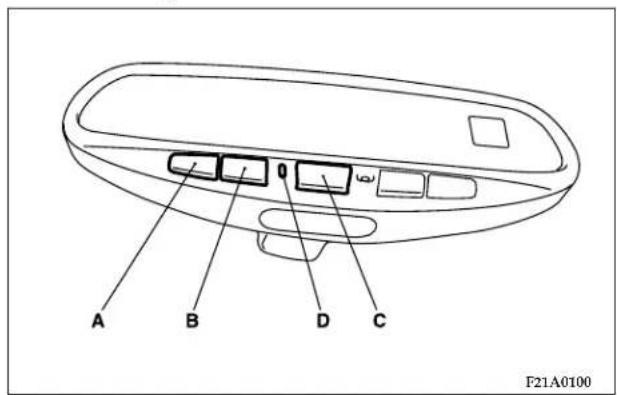
NOTE:
- Step 2 does not have to be followed to program additional hand held transmitters (E).
- Choose one of the three buttons to train. Place the hand held transmitter 1 to 3 inches from the universal transceiver while keeping its indicator light in view.
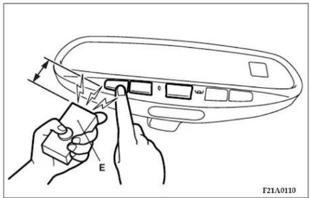
- Using both hands, press the hand held transmitter button and the desired universal transceiver button. Do not release the buttons until step 5 has been completed.
NOTE:
- Some entry gates and garage door openers may require you to replace step 4 with the procedures listed under Canadian Programming.
- The indicator light (D) will begin to flash, first slowly and then rapidly. The rapid flashing indicates successful programming. If after 90 seconds the indicator light does not flash rapidly or goes out, return to step 1 and repeat the procedure. To train the other buttons, repeat steps 3 and 4. Be sure to keep your hand held transmitters in case you need to retrain the universal transceiver.
Refer to the Rolling Code Programming or the Canadian/Gate paragraphs for additional procedures, if necessary.
If you do not successfully program the universal transceiver to learn the signal of your hand held transmitter, refer to the Rolling Code Paragraph, or call toll-free for customer assistance at 1–800–355–3515, or on the internet at www.homelink.jci.com.
Canadian Programming/Gate Programming
Canadian frequency laws, and the technology of some entry gates, require you to press and release the hand held transmitter button every two seconds during programming.
Continue to press and hold the universal transceiver button (A, B or C) while you press and release the hand held transmitter button until the frequency signal has been learned. The indicator light (D) will flash slowly and then rapidly when the programming is successful.
NOTE:
- When programming such a garage door opener or gate, unplug the device to prevent possible damage to the garage door or gate motor.
134 INSTRUMENTS AND CONTROLS
Operation
Press and hold the desired button (A, B or C) on the universal transceiver until the garage door or other device begins to operate. The indicator light (D) shows that the signal is being transmitted. The hand held transmitter (E) may also be used at any time.
NOTE:
- If you have difficulty in programming, call toll-free for customer assistance at 1-800-355-3515, or the internet at www.homelink.jci.com.
- If your hand held transmitter appears to program the universal transceiver, but your garage door or other device does not operate, and your device was manufactured after 1996, your garage door opener or other device may have a "Rolling Code" system.
To check if your device is protected by a "Rolling Code" system:
- Check the owner's manual for the device for mention of "Rolling Code".
- The hand held transmitter appears to program the universal transceiver but the universal transceiver does not activate the garage door.
- Press and hold the programmed button on the universal transceiver. If the indicator light (D) flashes rapidly and then stays on after 2 seconds, the device has the "Rolling Code" feature.
"Rolling Code" Programming
On garage door openers with the "Rolling Code" feature, the transmitter code changes after each use to prevent the copying of your code. Set the universal transceiver by following these steps:
NOTE:
- The assistance of a second person may make the following programming procedure quicker and easier.
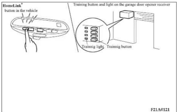
- Locate the training button on the garage door motor head unit. The exact location and color of the training button may vary by garage door opener manufacturer. If you have difficulty in locating the training button, check your garage door opener manual, or call toll-free for customer assistance at 1-800-355-3515, or on the internet at www.homelink.jci.com.
- Press and hold the training button on the garage door opener head unit This will activate the "training" light.
NOTE:
- After completing step 2, you have 30 seconds to start step 3.
- Return to the universal transceiver in the vehicle and firmly press and release the universal transceiver button (A, B or C). Press and release the button a second time to complete the training process. Some garage door openers may require you to do this procedure a third time to complete the training.
Your garage door opener should now recognize your universal transceiver. You may use either your universal transceiver or your original hand held transmitter (E) to open you garage door.
Reprogramming A Signal Button
- Press and hold the universal transceiver button (A, B or C) to be reprogrammed. Do not release until step 4 has been completed.
136 INSTRUMENTS AND CONTROLS
-
When the indicator light (D) begins to flash slowly (after 20 seconds) position the hand held transmitter (E) 1 to 3 inches away from the universal transceiver button to be trained.
-
Press and hold the hand held transmitter button.
-
The indicator light will begin to flash, first slowly, then rapidly. When the indicator lights begin to flash rapidly, release both buttons.
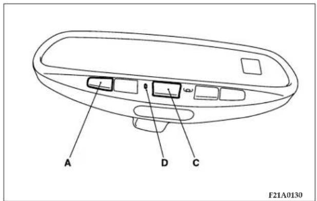
Security
If you sell your vehicle, be sure to erase the frequencies.
-
To erase all of the previously trained frequencies, hold down both outside buttons (A and C) until the indicator light (D) begins to flash after 20 seconds.
-
Release both buttons. Do not hold for longer than 30 seconds.
This device complies with FCC rules part 15. Operation is subject to the following conditions:
- This device may not cause harmful interference.
- This device must accept any interference that may be received including interference that may cause undesired operation.
NOTE:
- The transceiver has been tested and complies with FCC and DOC/MDC rules. Changes or modifications not expressly approved by the party responsible for compliance could void the user's authority to operate the device.
HomeLink ^® is a trademark owned by Johnson Controls, Inc.
STARTING AND DRIVING
CONTENTS
■ Break-in recommendations....142
■ Fuel selection 142
□ Gasoline additives ..... 1 4 3
□ Octane requirement ..... 1 4 3
□ Reformulated gasoline....143
□ Gasoline/Oxygenate blends ..... 1 4 4
□MMT in gasoline....144
□ Sulfur in gasoline. 144
□ Materials added to fuel. 145
□ Adding fuel. 145
■ Fuel economy 147
■ Ignition switch 147
■ Key reminder chime ..... 1 4 8
■ Theft protection....149
■ Steering lock 149
■ Starting....149
□ Tips for starting ..... 1 4 9
□ Normal conditions....150
□ Flooded engine....1 5 1
□ At extremely cold ambient temperature ..... 1 5 1
■ Automatic transaxle (if so equipped) ..... 1 5 1
□ Selector lever operation....152
140 STARTING AND DRIVING
□ Gear positions....154
□ Driving speed
(Vehicles with automatic transaxle) ..... 1 5 5
□ Holding on an upgrade....155
□ Transaxle reset mode ..... 1 5 6
■ Automatic transaxle Autostick
(if so equipped)....1 5 6
□ Selector lever operation ..... 1 5 7
□ Indicator lights....159
□ Selector positions (Main gate) ..... 1 6 0
□ Selector positions Manual gate Autostick ..... 1 6 1
□ Holding on an upgrade....163
□ Transaxle reset mode ..... 1 6 4
■ Manual transaxle (if so equipped) ..... 1 6 4
□ To start....165
□ Proper shift points....165
□ Recommended downshifting speed ..... 1 6 7
□ Driving precautions....167
■ Parking brake 167
■ Brake pedal....169
■ Power brakes 170
■ Brake pad wear alarm 170
■ Anti-lock braking (ABS) system (if so equipped)....171
□ General driving hints (standard/anti-lock brakes). 171
■ Steering wheel tilt lock lever ..... 1 7 3
■ Power steering 174
■ Inside Day/Night rearview mirrors ..... 175
□ Electrochromic inside rearview mirror (if so equipped)....176
□ Electrochromic mirror operation (if so equipped)....177
STARTING AND DRIVING 141
■ Cruise/speed control....187 □ Lights....198
□ To activate. 188 □ Fluid leaks 198
□ To deactivate....192 □ Driver....198
□ To resume the set speed . . . . . . . . . . . . . . . . . . 1 9 3 ■ Safe driving techniques . . . . . . . . . . . . . . . . . . . . . . 1 9 8
■ Traction control (if so equipped) ..... 194 ■ Driving, alcohol and drugs ..... 199
■ Catalytic converter ..... 195 ■ Tips for driving in various conditions ..... 199
■ Vehicle preparation before driving . . . . . . . . . 1 9 7 ■ Operation during cold weather . . . . . . . . . . 2 0 0
□ Seat belts and seats....197 ■ Trailer Towing....201
□ Defrosters....197 □ Warranty Requirements....201
□Tires....197
142 STARTING AND DRIVING
BREAK-IN RECOMMENDATIONS
Advanced automobile manufacturing techniques permit you to operate your new vehicle without experiencing a long break-in period of low-speed driving.
However, you can add to the future performance and economy of your vehicle by observing the following precautions during the first 300 miles (500 km).
It is recommended that you drive your vehicle at moderate speeds during the break-in period.
- Avoid racing the engine.
- Avoid harsh driving such as fast starts, sudden acceleration, prolonged high-speed driving and abrupt application of the brakes. These operations not only have a detrimental effect on the engine but also cause increased fuel and oil consumption, which could result in malfunction of engine components. Be particularly careful to avoid wide-open throttle acceleration in low gear.
- Do not overload the vehicle. Observe the seating capacity. (See "Weights" page 359)
- Do not use this vehicle for trailer towing during the break-in period.
FUEL SELECTION
Your vehicle is designed to use unleaded gasoline only. It is equipped with a fuel filler tube especially designed to accept only the smaller diameter unleaded gasoline dispensing nozzle.
WARNING!
Gasoline is highly flammable and explosive. You can be burned or seriously injured when handling it. When refueling this vehicle, always turn the engine off and keep flames, sparks, and smoking materials away. Always handle fuel in well-ventilated outdoor areas.
CAUTION!
Using leaded gasoline in your vehicle will damage the engine, catalytic converter, and the oxygen sensors. Further, using leaded gasoline is illegal, and will void warranty coverage of the engine, catalytic converter, and oxygen sensors.
Gasoline additives
Many fuel suppliers add detergents to their gasoline to minimize fuel injector fouling and to control intake valve deposits. These detergent gasolines are highly recommended for use in your vehicle. They help keep your engine in tune and your emission control system working properly.
Octane requirement
2.4 liter engine model
Your vehicle is designed to operate on unleaded gasoline having a minimum octane rating of 87 [(MON+RON)/2], or 91 RON.
3.0 liter engine model
Your vehicle is designed to operate on regular grade unleaded gasoline having a minimum octane rating of 87 [(MON+RON)/2], or 91 RON. If optimum performance is wanted, it is recommended to use premium grade unleaded gasoline having an octane rating of 91 [(MON+RON)/2], or 95 RON.
MON: Motor Octane Number
RON: Research Octane Number
Reformulated Gasoline
Many areas of the country require the use of cleaner burning fuel referred to as "Reformulated Gasoline".
Reformulated gasolines contain oxygenates, and are specially blended to reduce vehicle emissions and improve air quality.
The manufacturer supports the use of reformulated gaso-lines. Properly blended reformulated gasolines will provide excellent performance and durability of engine and fuel system components.
144 STARTING AND DRIVING
Gasoline/Oxygenate Blends
Some fuel suppliers blend unleaded gasoline with materials called oxygenates such as 10% ethanol, MTBE and ETBE. Oxygenates are required in some areas of the country during the winter months to reduce carbon monoxide emissions. Fuels blended with these oxygenates may be used in your vehicle.
CAUTION!
DO NOT use gasolines containing Methanol. Use of these blends may result in starting and driveability problems and may damage critical fuel system components.
Problems that result from using methanol/gasoline blends are not the responsibility of DaimlerChrysler Corporation and may not be covered by the vehicle warranty. While MTBE is an oxygenate made from Methanol, it does not have the negative effects of Methanol.
MMT in Gasoline
MMT is a manganese containing metallic additive that is blended into some gasoline to increase the octane number. Gasolines blended with MMT offer no performance advantage over gasolines of the same octane number that do not contain MMT. Gasolines blended with MMT have shown to reduce spark plug life and reduce emission system performance in some vehicles. DaimlerChrysler Corporation recommends using gasolines without MMT. Since the MMT content of gasoline may not be indicated on the pump, you should ask your gasoline retailer whether or not his/her gasoline contains MMT.
It is even more important to look for gasolines without MMT in Canada because MMT can be used at higher levels than allowed in the United States.
MMT is prohibited in both Federal and California reformulated gasolines.
Sulfur in Gasoline
If you live in the Northeast United States, your vehicle may have been designed to meet California low emission standards with cleaner burning California reformulated gasoline with low sulfur. If such fuels are not available in
states adopting California emission standards, your vehicle will operate satisfactorily on fuels meeting Federal specifications, but emission control system performance may be adversely affected.
Gasoline sold outside of California is permitted to have higher sulfur levels which may affect the performance of the vehicle's catalytic converter. This may cause the Check Engine Light to illuminate. The manufacturer recommends that you try a different brand of unleaded gasoline having lower sulfur to determine if the problem is fuel related prior to returning your vehicle to an authorized dealer for service.
CAUTION!
If the Malfunction Indicator Light (Service Engine Soon) is flashing, immediate service is required. See the On Board Diagnostics paragraph in the Maintenance section of this manual.
Materials Added to Fuel
All gasoline sold in the United States is required to contain effective detergent additives. Use of additional detergents or other additives is not needed under normal conditions and would result in additional cost. Therefore you should not have to add anything to the fuel.
Adding Fuel
NOTE: The fuel tank filler tube has a restricting door about 2 inches (50 mm) down from the opening. If fuel is poured from a portable container, the container should have a flexible nozzle long enough to force open the restricting door.
CAUTION!
To avoid fuel spillage and overfilling, do not "top off" the fuel tank after filling.
NOTE: When the fuel nozzle "clicks" or shuts off, the fuel tank is full.
146 STARTING AND DRIVING
NOTE: Tighten the gas cap until you hear a "clicking" sound. This is an indication that the gas cap is properly tightened.
The Malfunction Indicator Light (“SERVICE ENGINE SOON”) will come on if the gas cap is not properly secured. Make sure that the gas cap is tightened each time the vehicle is refueled.
WARNING!
A fire may result if gasoline is pumped into a portable container that is inside of a vehicle. You could be burned. Always place gas containers on the ground while filling.
Fuel Filler Cap (Gas Cap)
The gas cap is behind the fuel filler door, on the passenger's side of the vehicle. If the gas cap is lost or damaged, be sure the replacement cap is for use with this vehicle.
CAUTION!
Damage to the fuel system or emission control system could result from using an improper fuel tank filler tube cap (gas cap). A poorly fitting cap could let impurities into the fuel system.
CAUTION!
A poorly fitting gas cap may cause the Malfunction Indicator Light ("SERVICE ENGINE SOON") to turn on.
WARNING!
- Never have any smoking materials lit in or near the vehicle when the gas cap is removed or the tank filled.
- Never add fuel to the vehicle when the engine is running.
FUEL ECONOMY
Fuel economy is dependent on many factors. Your personal driving habits can have a significant effect on your fuel economy. Several recommendations for achieving maximum fuel economy are listed below.
- When pulling away from traffic lights or stop signs, accelerate slowly and smoothly.
- When parked for even a short period, do not idle the engine. Shut it off.
- Plan your trips to avoid unnecessary stops.
- Keep your tires inflated to the recommended pressures.
- For freeway driving, maintain a constant speed within the posted limits when traffic, roadway and weather conditions safely permit, for the best fuel economy.
- Keep your air filter clean and your vehicle lubricated according to the recommendations in this manual.
- Keep your vehicle "tuned-up". An out-of-tune engine wastes fuel and costs money.
- Reduce excess vehicle load.
IGNITION SWITCH
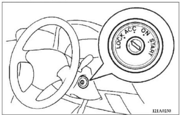
LOCK
For vehicles with a manual transaxle, when removing the key, push the key in at the "ACC" position and keep it depressed until it is turned to the "LOCK" position, and remove the key.
For vehicles with an automatic transaxle: When removing the key, first set the gear selector lever to the "P" (PARK) position, and then turn the key to "LOCK" and remove it.
148 STARTING AND DRIVING
NOTE: For vehicles with an automatic transaxle, the key cannot be removed unless the selector lever is set to the "P" (PARK) position.
ACC
Allows operation of electrical accessories with the engine off.
START
Engages the starter. After the engine starts, release the key and it will return automatically to the "ON" position.
ON
The engine runs and all accessories can be used.
NOTE: Do not use the "ON" position to operate accessories.
CAUTION!
- Do not remove the ignition key from the ignition switch while driving. The steering wheel will lock, causing loss of control.
- If the engine is turned off while driving, the power brake servomechanism will cease to function and braking efficiency will deteriorate. Also, the power steering system will not function and it will require greater effort to operate the steering.
- Do not leave the key in the "ON" position for a long time when the engine is not running; doing so will cause the battery to discharge.
- Do not turn the key to the "START" position when the engine is running; doing so could damage the starter motor.
KEY REMINDER CHIME
If the driver's door is opened while the ignition key is in the "LOCK" or "ACC" position, a warning chime sounds.
THEFT PROTECTION
CAUTION!
Always remove the key from the ignition switch and lock all doors when leaving the vehicle unattended. Always try to park your vehicle in a well lighted area.
The ignition key can only be removed in the "LOCK" position. If the key is left in the lock cylinder, a warning chime sounds when the driver's door is opened.
NOTE: If your vehicle is equipped with a Theft-alarm system, refer to "Theft-alarm system".
STEERING LOCK
Withdraw the key and the steering wheel will be locked. Turn the steering wheel to confirm that it is locked.
CAUTION!
If your vehicle needs to be towed, turn the key to the "ACC" position to unlock the steering wheel.
STARTING
Tips for starting
- Do not operate the starter motor continuously for longer than 15 seconds at a time; doing so could run down the battery. If the engine does not start, turn the ignition switch back to "LOCK", wait a few seconds, and then try again.
- If the engine will not start because the battery is weak or dead, refer to "Jump-starting the engine" section (page 273) for instructions on starting the engine.
- The engine is well warmed up if the pointer of the coolant temperature gauge starts to move. Extended warm up operation will result in excessive fuel consumption.
WARNING!
Never run the engine in a closed or poorly ventilated area any longer than is needed to move your vehicle in or out of the area. Carbon monoxide gas, which is odorless, colorless and extremely poisonous, could build up, and cause serious injury or death.
CAUTION!
- Do not start the vehicle by pushing or pulling.
- Do not run the engine at high rpm or drive the vehicle at high speed until the engine has had a chance to warm up.
- Release the ignition key as soon as the engine starts to avoid damaging the starter motor.
This vehicle is equipped with an electronically controlled fuel injection system that automatically controls fuel quantity. When starting the engine, there is normally no need to depress the accelerator pedal.
Normal conditions
The starting procedure is as follows:
- Insert the ignition key and make sure all occupants are properly seated with seat belts fastened.
- Depress and hold the brake pedal down with your right foot.
- Set the gearshift selector lever (manual transaxle) in the "N" (NEUTRAL) position, or the selector lever (automatic transaxle) in the "P" (PARK) position.
- Fully depress the clutch pedal (manual transaxle).
NOTE: For models equipped with a manual transaxle, the starter will not operate unless the clutch pedal is fully depressed (Clutch interlock).
-
After turning the ignition key to the "ON" position, make certain that all warning lights are functioning properly before starting the engine.
-
Turn the ignition key to the "START" position without depressing the accelerator pedal, and release the key when the engine starts.
NOTE: Slight noises may be heard on engine start-up.
These noises will disappear as you continue warming up the engine.
Flooded engine
If the engine has become flooded during starting, first operate the starter for 5 to 6 seconds while fully depressing the accelerator pedal (clear flood), then start the engine without depressing the accelerator pedal at all.
At extremely cold ambient temperature
If the engine won't start, depress the accelerator pedal about halfway while cranking the engine. Once the engine starts, release the accelerator pedal.
CAUTION!
When starting the engine, make sure that you step on the brake pedal. During very cold weather, when you start the engine while putting your foot on the accelerator pedal, move your foot to the brake pedal immediately after the engine has started.
AUTOMATIC TRANSAXLE (IF SO EQUIPPED)
The automatic transaxle is designed for optimum control and equipped with adaptive control capabilities. The electronically controlled transaxle optimally matches gear shifts to almost all driving and road conditions.
DRIVING UPHILL
The transaxle may not upshift to a higher gear if the computer determines the current speed cannot be maintained once a higher gear is engaged.
For smoother vehicle performance, if you release the throttle while climbing a steep grade, the transaxle may not upshift. This is normal, as the computer is controlling the shifting. After reaching the top of the hill, normal gear shift function will resume.
DRIVING DOWNHILL
When traveling down steep grades and depressing the brake pedal, the computer may automatically select a lower gear. This function assists engine braking efforts, reducing the need to use the brakes.
152 STARTING AND DRIVING
CAUTION!
The electronically controlled transaxle system is strictly intended to provide supplementary functions. When driving downhill under certain conditions, or immediately after starting when the automatic transaxle is cold, no automatic shift-down may be made. The driver should shift down to a low gear (3rd gear or 2nd gear), which will permit the engine to exert a braking effect.
NOTE: During the brake-in period or immediately after re-connection of the battery cable, the vehicle may not shift as smoothly. This does not indicate a faulty transmission. The transaxle system must have a short period to learn parameters for proper shifting. Shifting will become smooth after the transaxle has been shifted several times by the electronic control system.
Selector lever operation
As an additional safety precaution, models equipped with an automatic transaxle have a shift-lock device that holds the selector lever in the "P" (PARK) position. To move the selector lever from the "P" (PARK) position to another position, follow the steps below.
- Depress and hold down the brake pedal.
- Move the selector lever to the desired position.
NOTE: The selector lever cannot be moved from "P" (PARK) to another position if the ignition key is at the "LOCK" position, removed, or if the brake pedal is not depressed and held down.
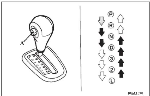
The indicator panel, on the console located at the driver's right, is illuminated for night driving.
Button (A) must be pushed while the brake pedal is depressed to move the selector lever.
Button need not be pushed to move the lever.
Button must be pushed to move the lever.
STARTING AND DRIVING 153
WARNING!
Always depress the brake pedal when shifting the selector lever into a gear from the "N" (NEUTRAL) position. When beginning to drive, do not shift the selector lever from the "N" (NEUTRAL) position while depressing the accelerator pedal; doing so may cause the vehicle to "jump" forward or backward.
CAUTION!
If the button is always depressed to operate the selector lever, the lever may be accidentally shifted into the "P", "R", 3, 2, "L" position. Be sure not to depress the button when performing the operations indicated by ↓ in the illustration.
NOTE: If the brake pedal is not depressed and held, the shift-lock device activates to prevent the selector lever from being moved from the "P" (PARK) position.
154 STARTING AND DRIVING
Gear positions
"P" PARK
The "P" (PARK) position supplements the parking brake by locking the transaxle while the vehicle is parked.
The engine can be started in this position.
Apply the parking brake before leaving the vehicle in this position.
"R" REVERSE
Shift into this position only after the vehicle has come to a complete stop.
CAUTION!
Never shift into the "P" (PARK) or "R" (REVERSE) position while the vehicle is in motion. If the lever is shifted into the "P" or "R" position while the vehicle is in motion, the transaxle may be damaged.
"N" NEUTRAL
The engine may be started in this position.
WARNING!
- Never move the lever to the "N" position while driving since you could accidentally move the lever into the "P" or "R" position, damaging the transaxle.
- To prevent the vehicle from rolling when stopped on a slope, the engine should be started in the "P" (PARK) position, not in "N" (NEUTRAL).
- Always keep your foot on the brake pedal when the vehicle is in "N" (NEUTRAL), or when shifting into or out of "N" (NEUTRAL), to maintain control.
"D" DRIVE
This position is used for most city and highway driving. Engine shifting is done automatically, depending on road conditions.
"3" THIRD / "2" SECOND
For driving slowly in heavy city traffic or on mountain roads where more precise speed control is desired.
Also use it when climbing long grades, and for engine braking when descending moderately steep grades.
Engine braking is automatically applied when necessary, depending on road conditions.
"L" LOW
This position is for driving up very steep hills and for engine braking at low speeds when descending steep gradients.
WARNING!
Be very careful not to shift into "L" suddenly. Doing so may cause the tires to slip.
Driving speed (Vehicles with automatic transaxle)
In order to avoid damage to the engine from excessively high rpm, do not exceed the listed driving speed when the selector lever is set to the "3" (THIRD) position, the "2" (SECOND) position or the "L" (LOW) position.
| Condition | Driving speed mph (km/h) | |
| 2.4 liter engine 3 | 0 liter engine | |
| “3” (THIRD) 11 | 4 (180) 118 (190) | |
| “2” (SECOND) 7 | 4 (115) 80 (130) | |
| “L” (LOW) 28 | (45) 31 (45) | |
WARNING!
Always obey posted speed limits. Use common sense and drive safely, regardless of posted speed limits. Drive at speeds that are safe for the traffic, weather, or road conditions.
Holding on an upgrade
To avoid transaxle overheating, never hold the vehicle stationary on an incline by using the accelerator pedal. Instead, use the brake pedal.
156 STARTING AND DRIVING
Transaxle Reset Mode
The transaxle is monitored for abnormal conditions. If a condition is detected that could cause damage, the transaxle automatically shifts into second gear. The transaxle remains in second gear despite the forward gear selected. Park (P), Reverse (R), and Neutral (N) will continue to operate. This Reset feature allows the vehicle to be driven to a dealer for service without damaging the transaxle.
If the problem has been momentary, the transaxle can be reset to regain all forward gears.
- Stop the vehicle and shift into PARK (P).
- Turn the key to OFF then start the engine.
- Shift into "D" and resume driving.
NOTE: Even if the transaxle can be reset, we recommend that you visit a dealer at your earliest possible convenience. Your dealer has diagnostic equipment to determine if the problem could recur.
If the transaxle cannot be reset, dealer service is required.
AUTOMATIC TRANSAXLE AUTOSTICK (IF SO EQUIPPED)
Designed for optimum control and equipped with adaptive control capabilities, the electronically controlled transaxle optimally matches gear shifts to almost all driving and road conditions.
DRIVING UPHILL
The transaxle may not upshift to a higher gear if the computer determines the current speed cannot be maintained once a higher gear is engaged.
For smoother vehicle performance, if you release the throttle while climbing a steep grade, the transaxle may not upshift. This is normal, as the computer is controlling the shifting. After reaching the top of the hill, normal gear shift function will resume.
DRIVING DOWNHILL
When traveling down steep grades and depressing the brake pedal, the computer may automatically select a lower gear. This function assists engine braking efforts, reducing the need to use the brakes.
CAUTION!
The electronically controlled transaxle system is strictly intended to provide supplementary functions. When driving downhill under certain conditions, or immediately after starting when the automatic transaxle is cold, no automatic shift-down may be made. The driver should shift down to a low gear (3rd gear or 2nd gear), which will permit the engine to exert a braking effect.
NOTE: During the brake-in period or immediately after re-connection of the battery cable, the vehicle may not shift smoothly. This does not indicate a faulty transmission. The transaxle system must have a short period to learn parameters for proper shifting. Shifting will become smooth after the transaxle has been shifted several times by the electronic control system.
Selector lever operation
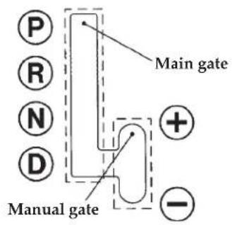
104B0060
The transaxle has 4 forward gears and 1 reverse gear. The individual gears are selected automatically, depending on the position of the gear selector lever, the speed of the vehicle, and the position of the accelerator pedal. The selector lever has 2 "gates": the main gate and the manual gate.
NOTE: For information on manual gate operation, please refer to "Autostick" on page 159.
158 STARTING AND DRIVING
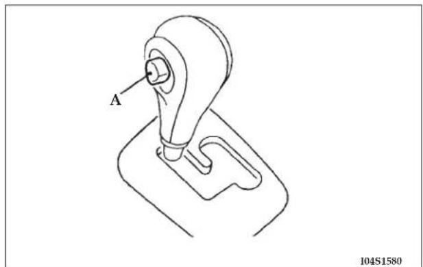
In the main gate, the selector lever has 4 positions and is equipped with a lock button (A) to prevent inadvertent selection of the wrong gear.
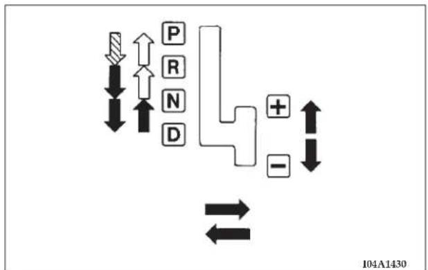
flowchart
graph TD
    A["↑"] --> B["↓"]
    C["↑"] --> D["↓"]
    E["P"] --> F["↑"]
    G["R"] --> H["↑"]
    I["N"] --> J["↑"]
    K["D"] --> L["↓"]
    M["+"] --> N["←"]
    O["-"] --> P["↓"]
    Q["104A1430"]
Button (A) must be pushed while the brake pedal is depressed to move the selector lever.
Button must be pushed to move the lever.
Button need not be pushed to move the lever.
WARNING!
Always depress the brake pedal when shifting the selector lever into a gear from the "N" (NEUTRAL) position. When beginning to drive, do not shift the selector lever from the "N" (NEUTRAL) position while depressing the accelerator pedal; doing so may cause the vehicle to "jump" forward or backward.
CAUTION!
If the button is always depressed to operate the selector lever, the lever may be accidentally shifted into the "P", "R" position. Be sure not to depress the button when performing the operations indicated by ↓ in the illustration.
NOTE:
If the brake pedal is not depressed and held, the shift-lock device activates to prevent the selector lever from being moved from the "P" (PARK) position.
Indicator lights
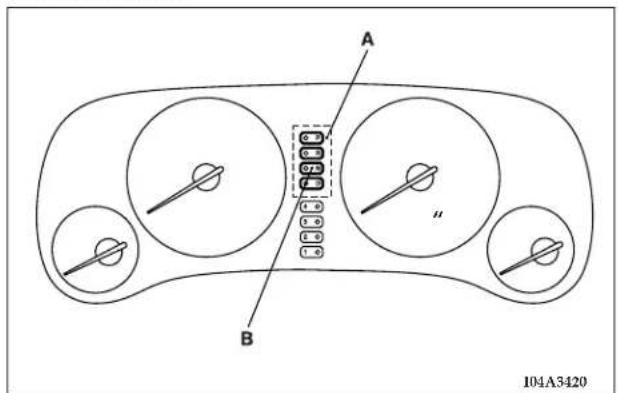
A - Selector lever position indicator light
B - "N" indicator light
The indicator lights in the instrument panel are for indicating the selector lever position (A).
If the "N" indicator light in the instrument panel flashes, there could be a malfunction with the automatic transaxle system. Identify and take action in accordance with the following procedures:
- The "N" indicator light flashes rapidly (twice per second) in the "D" or "Autostick" range.
If this occurs, the automatic transaxle fluid is overheating. Park your vehicle in a safe place but do not turn off the engine. Move the selector lever to the "P" position and open the hood. Keep the engine idling.
After a while, move the selector lever to the "D" or "Autostick" position and confirm that the "N" indicator light stops flashing. It is safe to continue driving if the "N" light no longer flashes.
Be sure to carry out this check with the selector lever in the "D" or "Autostick" position. The "N" indicator light warning function operates only in the "D" or "Autostick" range.
If the "N" indicator light continues flashing or flashes intermittently, have your vehicle inspected by an authorized dealer.
- The "N" indicator light flashes slowly (once per second) in the "D" or "Autostick" range.
The automatic transaxle safety device may be operating due to a malfunction.
Have your vehicle inspected by an authorized dealer as soon as possible.
Selector positions (Main gate)
P-PARK
This position locks the transaxle to prevent the vehicle from moving. The engine can be started in this position.
R - REVERSE
Shift into this position only after the vehicle has come to a complete stop.
CAUTION!
Never shift into the "P" (PARK) or "R" (REVERSE) position while the vehicle is in motion. If the lever is shifted into the "P" or "R" position while the vehicle is in motion, the transaxle may be damaged.
"N" NEUTRAL
The engine may be started in this position.
WARNING!
- Never move the lever to the "N" position while driving since you could accidentally move the lever into the "P" or "R" position, damaging the transaxle.
- To prevent the vehicle from rolling when stopped on a slope, the engine should be started in the "P" (PARK) position, not in "N" (NEUTRAL).
- Always keep your foot on the brake pedal when the vehicle is in "N" (NEUTRAL), or when shifting into or out of "N" (NEUTRAL), to maintain control.
"D" DRIVE
This position is used for most city and highway driving. Engine shifting is done automatically, depending on road conditions.
Selector positions Manual gate Autostick
Autostick is a driver-interactive transaxle that offers manual gear shifting capability to provide you with more control. Autostick allows you to maximize engine braking, eliminate undesirable upshifts and downshifts, and improve overall vehicle performance. This system can also provide you with more control during passing, city driving, cold slippery conditions, mountain driving, trailer towing, and many other situations.
Whether the vehicle is stationary or in motion, Autostick is selected by pushing the selector lever from the "D" position into the manual gate. To return to "D" range operation, push the selector lever back into the main gate.
In Autostick, gear shifts can be made rapidly by moving the selector lever backward and forward. In contrast to a manual transaxle, the Autostick allows gear shifts with the accelerator pedal depressed.
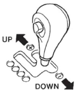
104S0170
-
(UP) : Push the lever forward once to shift up one gear.
– (DOWN): Pull the lever backward once to shift down one gear. -
Upward shifts do not take place automatically in Autostick. The driver must execute upward shifts in accordance with road conditions, make sure the engine rpm remains below the red zone on the tachometer.
- By rapidly moving the selector lever backwards (DOWN) twice, it is possible to skip one gear, (i.e. 3rd to 1st or 4th to 2nd). Since sudden engine de-acceleration or acceleration can cause a loss of traction, downshifts must be made carefully in accordance with the vehicle's speed.
NOTE
- In Autostick, only the 4 forward gears can be selected. To reverse or park the vehicle, move the selector lever to the "R" or "P" position in the main gate.
-
To maintain the required levels of vehicle performance and safety, the system may not allow certain gear shifts when the selector lever is operated, such as 4th gear at low speed.
-
In Autostick, downward shifts are made automatically when the vehicle slows down. When the vehicle stops, 1st gear is automatically selected.
- When starting out on slippery roads, push the selector lever forward into the + (UP) position. This puts the transmission into 2nd gear and is better for starting out on slippery roads. Push the selector lever to the - (DOWN) side to shift back to 1st gear.
- Move the selector lever gently between the manual and main gates and between positions in the manual gate. Undue force could damage the selector lever.
Indication lights
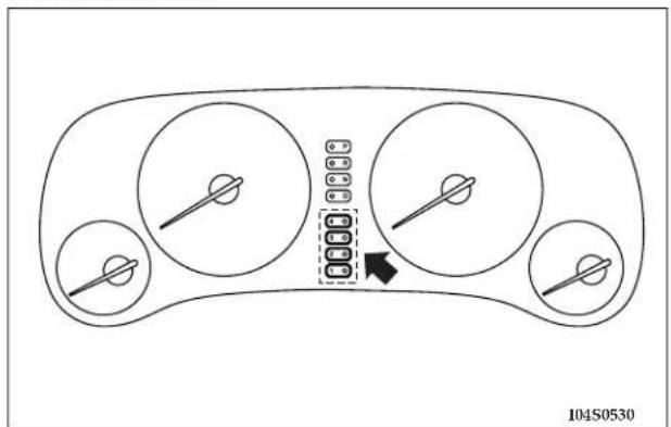
natural_image
Diagram of a car dashboard with four circular gauges and a central indicator box, no text or symbols present.In Autostick, the currently selected gear is indicated by the lights on the instrument panel.
NOTE: When Autostick is selected, the "D" indicator goes off.
Holding on an upgrade
To avoid transaxle overheating, never hold the vehicle stationary on an incline by using the accelerator pedal. Instead, use the brake pedal.
164 STARTING AND DRIVING
Transaxle Reset Mode
The transaxle is monitored for abnormal conditions. If a condition is detected that could cause damage, the transaxle automatically shifts into second gear. The transaxle remains in second gear despite the forward gear selected. Park (P), Reverse (R), and Neutral (N) will continue to operate. This Reset feature allows the vehicle to be driven to a dealer for service without damaging the transaxle.
If the problem has been momentary, the transaxle can be reset to regain all forward gears.
- Stop the vehicle and shift into PARK (P).
- Turn the key to OFF then start the engine.
- Shift into "D" and resume driving.
NOTE: Even if the transaxle can be reset, we recommend that you visit a dealer at your earliest possible convenience. Your dealer has diagnostic equipment to determine if the problem could recur.
If the transaxle cannot be reset, dealer service is required.
MANUAL TRANSAXLE (IF SO EQUIPPED)
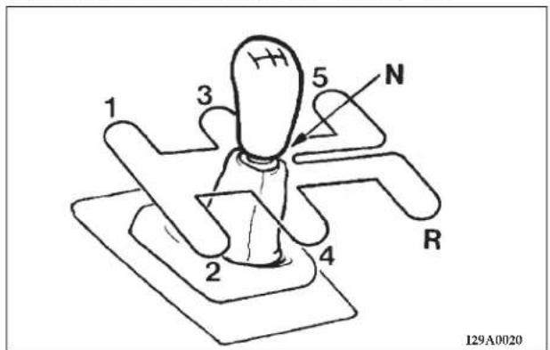
The shift pattern is shown on the gearshift lever. Depress the clutch pedal fully while shifting gears.
NOTE: During cold weather, shifting may be difficult/stiff until the transaxle lubricant has warmed up. This is normal and not a sign of a problem.
To start
Depress the clutch pedal fully and shift into 1st. Then gradually release the clutch pedal while depressing the accelerator pedal.
CAUTION!
- Do not move the gearshift lever into the "R" (REVERSE) while the vehicle is moving forward; doing so will damage the transaxle.
- Do not rest your foot on the clutch pedal as this will cause premature clutch wear or damage.
- Do not coast in the "N" (NEUTRAL) position (illegal in many states).
- Do not use the gearshift lever as a hand rest. This can result in premature wear of the transaxle shift forks.
NOTE
-
If it is hard to shift into 1st, depress the clutch pedal again; the shift will then be easier to make.
-
To shift into reverse from 5th gear, move the gearshift lever to the "N" (NEUTRAL) position, and then shift into reverse. Never shift into the "R" position when the vehicle is moving.
Proper shift points
Always use care to change gears with the vehicle speed matching the engine speed. Proper shifting will improve fuel economy and prolong engine life.
CAUTION!
Avoid downshifting that may cause the tachometer pointer to enter the red zone. This puts the engine at risk of being damaged.
Upshifting
In order to efficiently utilize your manual transaxle for both fuel economy and performance, it should be shifted as listed below.
At low altitude locations, shift at the vehicle speeds listed for acceleration. Earlier upshifts during cruise conditions (relatively steady speeds) will result in increased fuel economy.
2.4 liter engine
| Condition Upshift speedsmph (km/h) | |
| Acceleration Cruise | |
| 1st to 2nd 15 (25) 13 (20) | |
| 2nd to 3rd 23 (35) 18 (30) | |
| 3rd to 4th 34 (55) 33 (53) | |
| 4th to 5th 43 (70) 40 (65) | |
3.0 liter engine
| Condition Upshift speedsmph (km/h) | |
| Acceleration Cruise | |
| 1st to 2nd 15 (25) 13 (20) | |
| 2nd to 3rd 23 (35) 21 (34) | |
| 3rd to 4th 34 (55) 33 (53) | |
| 4th to 5th 43 (70) 37 (60) | |
In high altitude locations, it should be upshifted as listed below.
| Condition Upshift speeds mph (km/h) |
| 1st to 2nd 15 (25) |
| 2nd to 3rd 25 (40) |
| 3rd to 4th 40 (65) |
| 4th to 5th 45 (70) |
Downshifting
It is recommended that you downshift to a lower gear according to the table as necessary to maintain desired speeds.
Avoid downshifting at too high a speed; the engine may suffer damage.
To maintain a safe speed and prolong brake life, shift down to 2nd or 1st when descending a steep grade.
Downshifting is also important to avoid "lugging" the engine at too low a speed, such as when turning a corner or when driving up a steep grade.
Recommended downshifting speed
| Downshifting speed mph (km/h) | Condition |
| Under 20 (30) | 3rd to 2nd4th to 2nd5th to 2nd |
| 20 to 30 (30 to 45) | 4th to 3rd5th to 3rd |
Driving precautions
- The table below indicates the driving speed ranges that may be driven in each gear without causing the engine to operate in excessive engine speeds.
Possible driving speed
| Condition | 2.4 liter engine 3.0 | liter engine | |
| Vehicles with 205/60R16 21 tire tire | Vehicles with 15/50R17 | ||
| 1st 31 mph (50 km/h) | 34 mph (55 km/h) | ||
| 2nd 59 mph (95 km/h) | 55 mph (90 km/h) | ||
| 3rd 83 mph 86 mph 83 mph (135 km/h) (140 km/h) (135 km/h) | |||
| 4th | 114 mph (185 km/h) | 118 mph (190 km/h) | |
PARKING BRAKE
When the parking brake is applied with the ignition on, the Brake Light in the instrument cluster will come on.
NOTE: This light only shows that the parking brake is on. It does not show the degree of brake application.
168 STARTING AND DRIVING
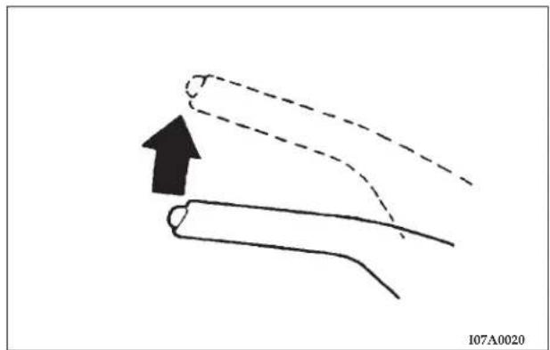
natural_image
Diagram showing a curved pipe with an arrow indicating upward motion, no text or symbols presentBefore leaving the vehicle, make sure that the parking brake is set. To set the parking brake, pull up firmly on the lever. Also place the gear selector in the Park position (automatic transaxle) or Reverse (manual transaxle). To release the parking brake, apply the brake pedal and pull
up on the parking brake lever. Push the release button and lower the lever fully.
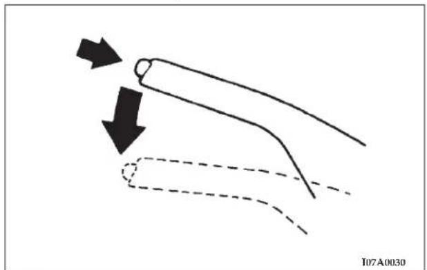
natural_image
Diagram showing a curved object with arrows indicating motion or force direction, no text or symbols presentWhen parking on a hill, it is important to set the parking brake before placing the gear selector in Park, otherwise the load on the transmission locking mechanism may make it difficult to move the selector out of Park. As an added precaution, turn the front wheels toward the curb on a downhill grade and away from the curb on a uphill grade.
You should always apply the parking brake before leaving the vehicle.
WARNING!
- Leaving children in a vehicle unattended is dangerous for a number of reasons. A child or others could be injured. Children should be warned not to touch the parking brake or the gear selector. Don't leave the keys in the ignition. A child could operate power windows, other controls, or move the vehicle.
- Be sure the parking brake is fully disengaged before driving; failure to do so can lead to brake failure and an accident.
BRAKE PEDAL
Excessive use of the brake can cause fading, resulting in poor brake response and premature wear of brake linings.
When driving down a long or steep grade, use engine braking by shifting the transaxle into a lower gear (manual transaxle and Autostick A/T) or "3" (THIRD) or "2" (SECOND) or "L" (LOW) position (except Autostick A/T).
WARNING!
Do not leave any objects on the floor near the brake pedal or permit a floor mat to interfere with the brake pedal. Doing so could prevent proper depression of the pedal. Make sure that the pedal can be operated freely at all times.
170 STARTING AND DRIVING
WARNING!
Riding the brakes can lead to brake failure and possibly an accident. Driving with your foot resting or riding on the brake pedal can result in abnormally high brake temperatures, excessive lining wear, and possible brake damage. You wouldn't have your full braking capacity in an emergency.
POWER BRAKES
Your vehicle is equipped with power brakes as standard equipment. In the event you lose power assist for any reason (for example, repeated brake applications with the engine off), the brakes will still function. The effort required to brake the vehicle will be substantially increased over that required with the power system operating.
If either of the two hydraulic systems lose normal capability, the remaining system will still function with some loss of overall braking effectiveness. This will be evident by increased pedal travel during application, greater pedal force required to slow or stop, and activation of the Brake Warning Lamp during brake use.
WARNING!
- Never coast downhill with the engine OFF. Keep the engine running whenever the vehicle is in motion. If the engine is stopped while driving, the power assist servomechanism will cease to function and braking efficiency will deteriorate.
- If power assist is lost or if either brake hydraulic systems lose normal capability, take your vehicle to an authorized dealer immediately.
BRAKE PAD WEAR ALARM
The disc brakes are equipped with an alarm device that produces a metallic sound (squeal) when the brake pads have worn down to the serviceable limit. If you hear this sound, have the brake pads replaced at an authorized dealer.
WARNING!
Driving on worn brake pads can reduce your ability to stop, and can result in an accident.
ANTI-LOCK BRAKING (ABS) SYSTEM (IF SO EQUIPPED)
The ABS gives increased vehicle stability and brake performance under most braking conditions. The system automatically “pumps” the brakes during severe braking conditions to prevent wheel lock up.
All vehicle wheels and tires must be the same size and tires must be properly inflated to produce optimal signals for the computer. However, the system will compensate when the compact spare is in use.
During stops where ABS is activated, a vibration of the brake pedal may be felt and associated system noises may be heard.
NOTE: Pumping of the brake pedal will diminish the effectiveness of Anti-lock brakes and may lead to an
accident. Pumping makes the stopping distance longer. Just press firmly on your brake pedal when you need to slow down or stop.
General driving hints (standard/anti-lock brakes)
- During anti-lock braking, steering differs slightly from normal driving conditions. Be sure to operate steering wheel carefully.
- The anti-lock braking system is not restricted to situations where brakes are applied suddenly. This system may also operate to prevent wheel lock when driving over manholes, steel roadwork plates, road markings, or any uneven road surface.
-
Always maintain a safe distance from vehicles in front of you. If your vehicle is equipped with Anti-lock braking system, allow for a greater braking distance when:
-
Driving on gravel or snow-covered roads.
- Driving with tire chains installed.
- Driving on uneven road surfaces.
172 STARTING AND DRIVING
CAUTION!
- Anti-lock braking system can not prevent accidents. It remains the driver's task to exercise safety precautions and to drive prudently.
- To prevent failure of the anti-lock braking system, be sure all 4-wheels and tires are the same size and type (space saver spare excluded).
- If the anti-lock brake system warning light illuminates after starting the engine or while driving, it indicates that the anti-lock braking system is not functioning and that only the normal brake system is in operation. (The normal brake system will still function properly.)
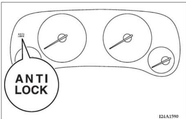
NOTE
- After the vehicle is driven for a while a whining sound and the sound of a motor operating will be heard from the engine compartment. These are normal sounds of the anti-lock braking system performing a self check and do not indicate a malfunction.
- The anti-lock braking system becomes operative after the vehicle has accelerated to a speed over approximately
6 mph (10 km/h). It stops operating when the vehicle decelerates to a speed below approximately 3 mph (5 km/h).
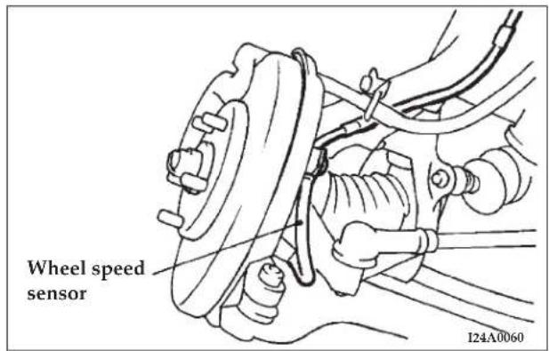
- After driving on snow or icy roads, remove any snow and ice that may have adhered to the wheel areas. When doing this be careful not to damage the wheel speed sensors and cables located at each wheel on vehicles equipped with an anti-lock braking system.
STEERING WHEEL TILT LOCK LEVER
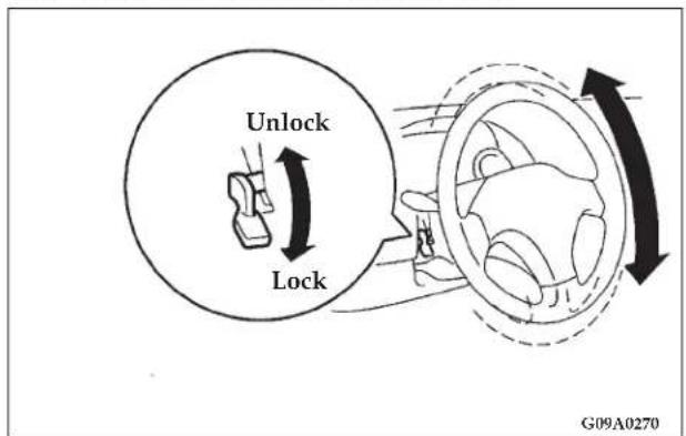
To adjust the steering wheel height, release the tilt lock lever while raising or lowering the steering wheel to the desired height.
After adjustment, securely lock the lever by pulling it downward.
174 STARTING AND DRIVING
WARNING!
- After adjustment, to the desired height, check to be sure that the lever is locked.
- Do not attempt to adjust the steering wheel while driving. This can be dangerous.
POWER STEERING
Your vehicle is equipped with power assisted steering as standard equipment. The power assisted steering system of your vehicle provides mechanical steering capability in the event power assist is lost.
If for some reason the hydraulic pressure is interrupted, it will still be possible to steer your vehicle. Under these conditions you will observe a substantial increase in steering effort. Should loss of hydraulic pressure occur take your vehicle to an authorized dealer.
WARNING!
Never turn off the engine while the vehicle is moving. Your ability to control the vehicle may be seriously reduced.
CAUTION!
Do not leave the steering wheel in the fully turned position. This can cause the power steering pump to be damaged due to poor lubrication.
- Do not attempt to adjust the rearview mirrors while driving. This can be dangerous.
- Your passenger's side mirror is convex. The objects you see in the mirror will look smaller and farther away than they actually are. Do not use this mirror to estimate the distance of following vehicles when changing lanes.
Type 1
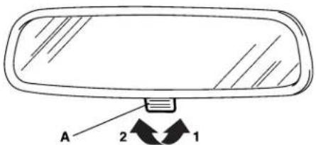
108A0620
Adjust the inside mirror to maximize the view through the rear window. Make this adjustment while the day/night knob (A) is in the daytime position (1). To reduce glare from other vehicle's headlights, switch the lever to the night position (2).
176 STARTING AND DRIVING
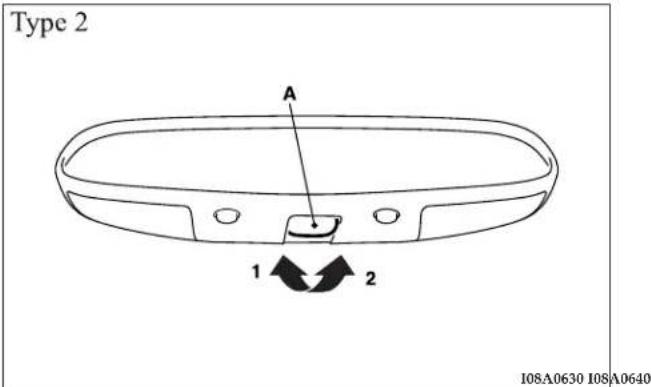
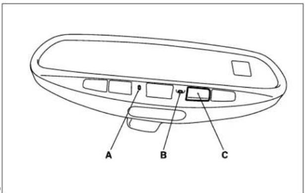
Electrochromic inside rearview mirror (if so equipped)
When the ignition key is in the "ACC" or "ON" position, the green indicator (A) should be illuminated. If not, press the display switch (C) for more than 6 seconds, less than 9 seconds, until the indicator illuminates. Now the mirror automatically dims to the proper level to minimize glare from lights behind you after dark.
To turn off the function, press the display switch (C) more than 6 seconds, less than 9 seconds. When the green indicator (A) goes off, the automatic anti-glare will not function.
To turn the function back on, press the display switch (C) more than 6 seconds, less than 9 seconds.
NOTE:
- Do not spray glass cleaner on the sensor (B), as reduced sensitivity could result.
Electrochromic mirror operation (if so equipped)
Press the button to operate devices such as garage door openers, motorized gates, or home lighting. → P. 130
NOTE: Garage door button must be programmed.
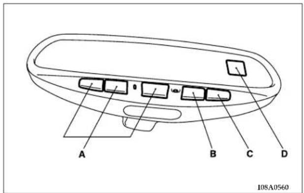
B - Display switch
Press the switch to change the mode of compass, outside temperature and anti-glare operation. → P. 176.
C - Dome light switch → P. 175.
D - Display.
The compass and outside temperature are displayed. To turn on/off the display, press the display switch (C) less than 3 seconds. → P. 177.
178 STARTING AND DRIVING
How to change the display mode
The mode will change in order by pressing the display switch for the following seconds.
- When the ignition key is "ACC" or "ON" position, automatic anti-glare operate and current outside temperature and compass are displayed.
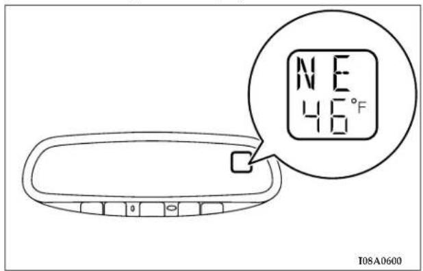
- If you press the display switch less than 3 seconds, you can turn on/off the display.
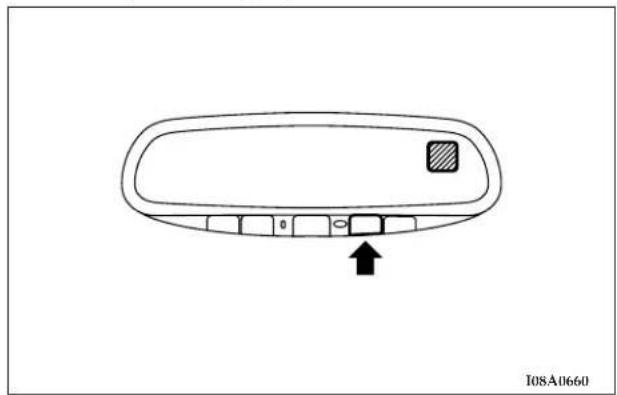
natural_image
Diagram of a vehicle rearview mirror with a small inset panel and an arrow pointing to the front panel (no text or symbols)- If you press the display switch more than 3 seconds, less than 6 seconds, you can alternate the temperature reading between Fahrenheit and Celsius. → P. 180.
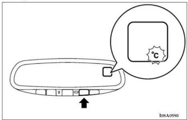
180 STARTING AND DRIVING
-
If you press the display switch more than 6 seconds, less than 9 seconds, you can turn on/off the automatic anti-glare. → 175
-
If you press the display switch more than 9 seconds, less than 12 seconds, you can adjust for compass variance. →181
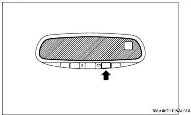
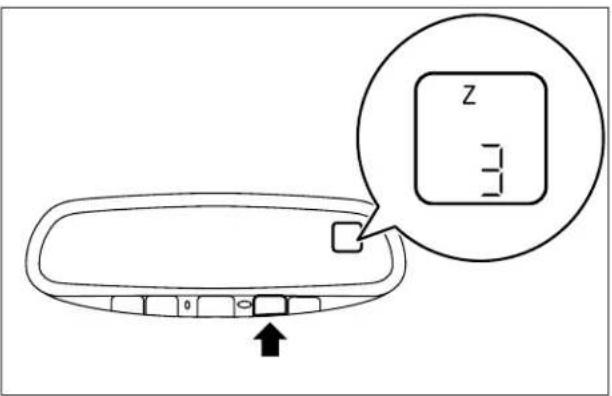
- If you press the display switch more than 12 seconds, you can recalibrate compass variance. →184
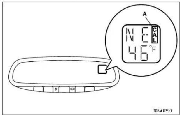
Outside temperature (if so equipped)
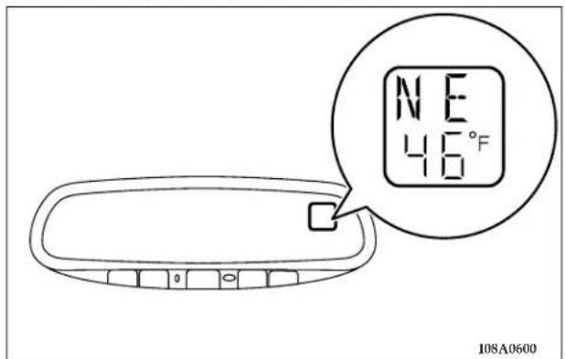
When the ignition key is in the "ACC" or "ON" position, the current outside temperature is displayed.
182 STARTING AND DRIVING
To alternate the temperature reading between Fahrenheit and Celsius
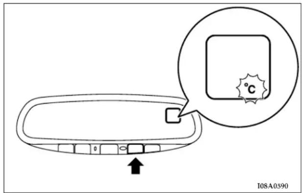
Press the display switch above 3 seconds, less than 6 seconds until the display blinks °F and °C.
Press the display switch to toggle between the Fahrenheit and Celsius readings within 5 seconds.
After 5 seconds of inactivity, the original item (Outside temperature/Compass) is again displayed.
NOTE
- The outside temperature can be displayed from -40^ (-40°C)
- If the outside temperature is below -40^ ( -40^ ) or over 140^ ( 60^ ) an error message “SC” or “OC” will be shown in the display. If an error message (“SC” or “OC”) will be shown in the display, have the system checked at an authorized dealer.
- If the outside temperature drops below about 37^ F ( 3^ C)
- The outside temperature displayed may differ from the actual temperature on account of surrounding conditions, driving conditions, etc.
Compass operation
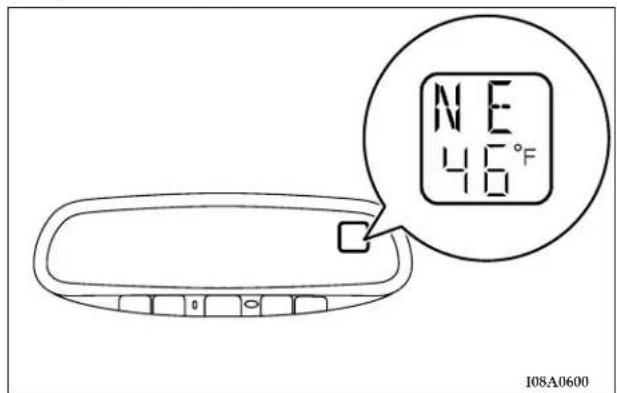
When the ignition key is in the "ACC" or "ON" position, the vehicle's current directional heading (N, NE, E, SE, S, SW, W and NW) will be displayed.
Magnetic variation of compass
Under certain circumstances, as during a long distance cross-country trip, it will be necessary to adjust for magnetic variation of compass. Magnetic variation of compass is the difference between earth's magnetic north and true geographic north. If not adjusted to account for magnetic variation of compass, your compass could give false readings.
To adjust for magnetic variation of compass
- Press the display switch more than 9 seconds, less than 12 seconds. The current zone number will appear in the display.
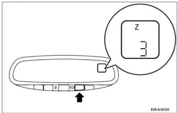
184 STARTING AND DRIVING
- Find your current location and variance zone number on the zone map.
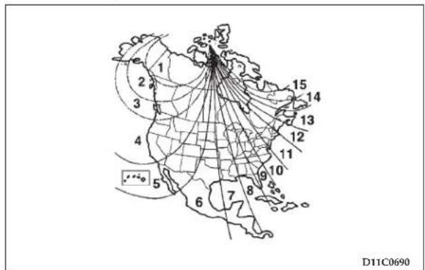
- Press the display switch until the new zone number appears in the display. After 5 seconds of inactivity, the original item (Outside temperature/Compass) displayed again.
NOTE
- Do not attach ski racks, antennas, or any other object to the vehicle by means of a magnet. Such magnets will affect the operation of the compass.
- If the compass deviates from the correct indication soon after repeated adjustment, have the compass checked at an authorized dealer.
- The compass may not indicate the correct compass point in the places shown below:
• Vehicles in tunnels or parked in buildings
- Expressways, near railroads, underneath railroad cables, or over subways
- Near transformer stations or high voltage power lines
In these cases, the correct direction will be displayed once the vehicle returns to a place where the earth's magnetic field is stable.
To calibrate the compass
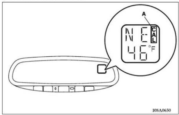
If the display reads "CAL" (A), there may be a strong magnetic field interfering with the compass. In this case, the compass may need calibration.
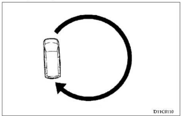
natural_image
Simple diagram showing a car moving in a circular cycle with an arrow indicating clockwise motion (no text or symbols)If the "CAL" is displayed, drive the vehicle in a circle at about 5 mph (8km/h) or less until the "CAL" goes off.
186 STARTING AND DRIVING
If the "CAL" is not displayed, but compass calibration is required, press and hold the display switch for 12 seconds, or until "CAL" is displayed. With "CAL" displayed, drive the vehicle in a circle at less than 5mph (8km/h) or less until the "CAL" goes off.
Cleaning of the mirror
When cleaning the mirror, use a paper towel or similar material dampened with glass cleaner. Do not spray glass cleaner directly on the mirror as that may cause the liquid cleaner to enter the mirror housing.
Electric remote-controlled outside mirrors
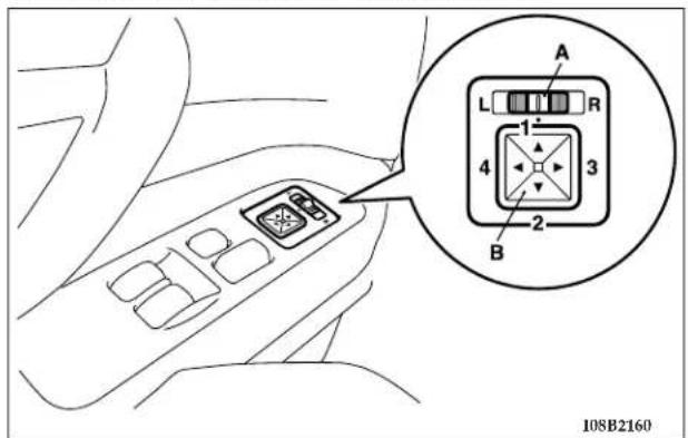
The outside rearview mirrors can be adjusted when the ignition key is in the "ON" or "ACC" position.
Place the lever to the same side as the mirror whose adjustment is desired:
L - Left outside mirror adjustment
R - Right outside mirror adjustment
NOTE
• After adjustment, return the lever to the centered position.
Press the left, right, up or down switches to adjust the mirrors as desired.
- Up
- Down
- Right
- Left
CRUISE/SPEED CONTROL
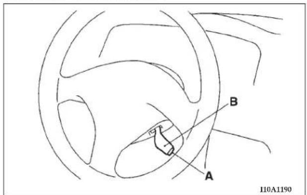
Cruise/speed control is an automatic speed control system. It lets you keep the same driving speed. Cruise/speed control can be used at 25mph (40km/h) or more. It is especially useful for freeway driving. Cruise/speed control does not work at speeds below about 25mph (40km/h).
A - Main switch
B - Cruise/speed control lever
188 STARTING AND DRIVING
CAUTION!
- For safety reasons, the main switch (A) should be set to the OFF position when you are not using the cruise/speed control system.
- Cruise/speed control is not recommended when driving conditions will not allow you to stay at the same speed, such as in heavy traffic or on roads that are winding, icy, snow-covered, wet, or slippery, or on a steep downhill.
- For vehicles with manual transaxles, if you shift to "N" (Neutral) in cruise/speed control mode without pressing the clutch first, the engine will run too fast and might be damaged.
NOTE
- Cruise/speed control may not be able to keep your speed on uphills or downhills.
- Your speed may drop on a steep uphill. You must use the accelerator if you want to stay at your set speed.
- Your speed may increase to more than the set speed on a steep downhill. You must use the brake to control your speed. If your speed increases too much, turn off the cruise/speed control. (Refer to the section "To deactivate" on page 190.)
To activate
- Momentarily push in the main switch (A) at the end of the cruise/speed control lever.
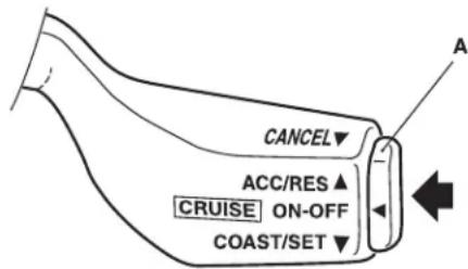
I10A1490
- When the main switch (A) is ON, the "CRUISE" control light on the instrument cluster will illuminate.
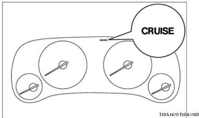
- Pull the lever (B) down while driving at the desired speed.
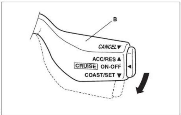
To increase the set speed
There are 2 ways to increase the set speed.
190 STARTING AND DRIVING
Cruise/speed control lever
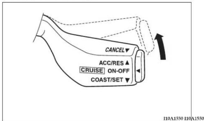
Pull the cruise/speed control lever up and hold it. Your speed will then gradually increase. When you reach your desired speed, release the switch. Your cruising speed is now set.
To increase your speed in small amounts, pull the cruise/ speed control lever up for less than 1 second and release it. Each time you pull the lever up, your vehicle will go about 1 mph (1.6km/h) faster.
Accelerator
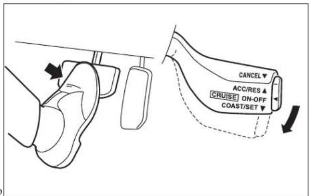
Press the accelerator pedal to reach your desired speed. Pull the cruise/speed control lever down for a moment, then release it.
To decrease the set speed
There are 2 ways to reduce the set speed.
Cruise/speed control lever
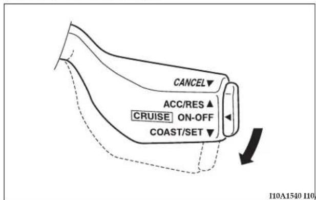
Brake pedal
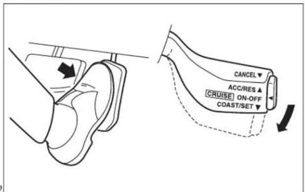
Pull the cruise/speed control lever down and hold it while driving at the set speed, and you will slow down (coast) gradually. When your desired low speed is reached, release the lever.
To slow down in small amounts, press the cruise/speed control lever down for less than 1 second and release it. Each time you press the lever down, your vehicle will slow down by about 1 mph (1.6km/h).
Press the brake pedal (which disengages the cruise/speed control), then pull the cruise/speed control lever down momentarily to set a new desired cruise speed.
192 STARTING AND DRIVING
To accelerate for passing
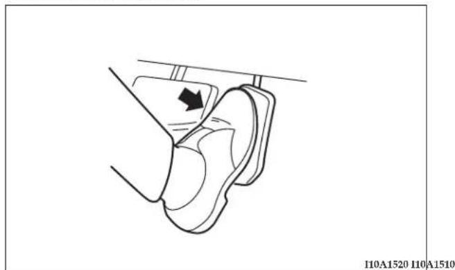
natural_image
Technical line drawing of a mechanical component with an arrow indicating direction (no text or symbols)Press the accelerator pedal as you would normally. When you release the pedal, the cruise/speed control will return to your set speed.
To deactivate
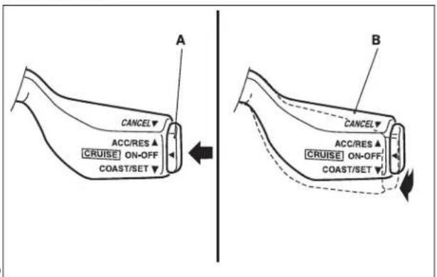
The cruise/speed control can be turned off as follows:
- Push the main switch (A) at the end of the lever (Main switch OFF).
- Pull the cruise/speed control lever (B) toward you.
The cruise/speed control can be turned off automatically in any of the following ways:
- By slightly tapping the brake pedal or pressing down on it to slow your speed.
- By pressing the clutch pedal down (for vehicles with manual transaxle).
- By moving the selector lever to "N" (for vehicles with automatic transaxle).
- When your speed slows to 10 mph (15km/h) or more below the set speed because of a hill, etc.
- When your speed slows to 25mph (40km/h) or less.
WARNING
- For vehicles with automatic transaxles, although the cruise/speed control can be turned off by moving the selector lever to the "N" position, never move the selector lever to the "N" position while driving. You would have no engine braking and could cause a serious accident.
To resume the set speed
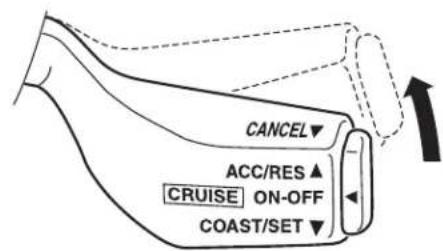
110A1530
If the speed memory has not been erased, resume the previously set speed by pulling the cruise/speed control lever up while driving at a speed of 25 mph (40km/h) or higher.
Under either of the following conditions, however, using the switch does not allow you to resume the previously set speed. In these situations, repeat the speed setting
194 STARTING AND DRIVING
procedure:
(1) The ignition key is turned OFF.
(2) The main switch is turned OFF.
TRACTION CONTROL (IF SO EQUIPPED)
On slippery surfaces, traction control system prevents the drive wheels (front wheels) from excessive spinning, during starting or while accelerating in turns on slippery roads.
NOTE
- The traction control system functions at speeds below about 25mph (40km/h).
- Some vibration will be felt in the vehicle body and a whining sound of a motor will be heard from the engine compartment when the traction control system functions. This is a normal result of the traction control system operation, and does not indicate a malfunction.
Driving hints
- Traction control system does not actively apply brakes. Always decelerate the vehicle sufficiently before entering corners or bends.
- On snowy or icy roads, drive slowly using tire chains or snow tires.
- Never mix or use tires of different size since the traction control system could function incorrectly and make safe driving difficult.
Warning light
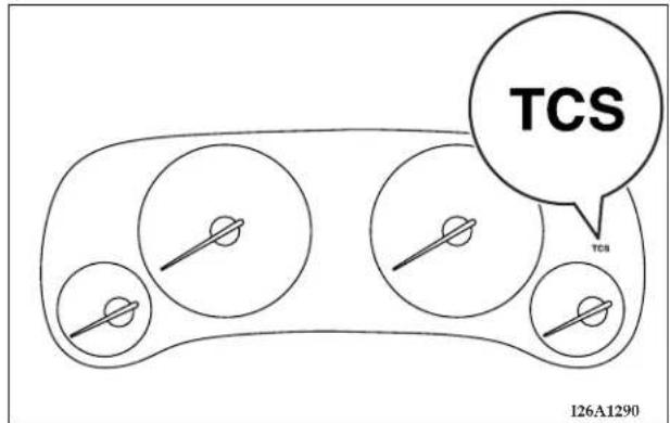
When the ignition key is turned to "ON", the warning light illuminate and go out after a few seconds.
| CAUTION |
| • If the warning light illuminates, a malfunction may have occurred in the system.When this happens, have your vehicle checked at an authorized dealer. |
CATALYTIC CONVERTER
The catalytic converter requires the use of unleaded fuel only. Leaded gasoline will destroy the effectiveness of the converter.
Under normal operating conditions the catalytic converter does not require maintenance. However, it is important to keep the engine properly tuned to assure proper converter operation and prevent damage.
CAUTION!
Damage to the catalytic converter can result if your vehicle is not kept in proper operating condition. In the event of an engine malfunction, particularly one involving engine misfire or other apparent loss of performance, have your vehicle serviced promptly. Prolonged operation of your vehicle while it is overheated may result in damage to the converter and vehicle.
WARNING!
- Do not park or operate this vehicle in areas where combustible materials such as dry grass or leaves can come in contact with a hot exhaust, since a fire could occur.
- Undercoating should not be applied to the catalytic converter.
To minimize the possibility of catalytic converter damage:
- Use UNLEADED GASOLINE ONLY of the type recommended in "Fuel selection".
- Do not drive with an extremely low fuel level; running out of fuel could damage the catalytic converter.
- Do not shut off the engine or interrupt the ignition when the transaxle is in gear and the vehicle is in motion.
- Do not try to start the engine by pushing or towing the vehicle. If the battery is weak or discharged, use jumper cables to properly start the engine.
- Do not idle the engine with any spark plug wires disconnected or removed, such as when performing diagnostic tests.
- Do not idle the engine for prolonged periods if it is idling roughly or otherwise obviously malfunctioning.
-
To prevent the catalytic converter from being damaged due to unburned gas, do not race the engine when turning off the ignition switch.
-
Stop driving the vehicle if you think the performance is noticeably less, or that there is unnecessary engine miss, or any other engine trouble, such as with the ignition, etc. If it is impractical to stop driving immediately, reduce the speed and drive for only a short time. Have an inspection made by an authorized dealer as soon as possible.
- In an unusual event of a severe engine malfunction, a scorching odor may indicate severe and abnormal catalytic converter overheating. If this occurs, the vehicle should be stopped in a safe place, the engine shut off and the vehicle allowed to cool. Once the engine is cool, the vehicle should immediately be taken to a dealer for service.
VEHICLE PREPARATION BEFORE DRIVING
Before starting on a trip, perform the following checks to obtain the greatest possible enjoyment and safety from your vehicle:
Seat belts and seats
- Before starting the vehicle, make certain that you and all your passengers are seated and properly wearing the seat belts (with children in the rear seat, in appropriate restraints), and that all doors are locked.
- Adjust the driver's seat as far back as possible, while still maintaining good visibility, and good control of the steering wheel, brakes, accelerator, and controls. Examine the instrument panel indicators for any possible malfunction.
- Have the front passenger adjust their seat as far rearward as possible.
Defrosters
Check operation by selecting the defroster mode and set the blower switch for high speed operation. You should be able to feel the air directed against the windshield. (See "Heater / Air conditioning" page 232.)
Tires
Examine all tires for excessive tread wear or uneven wear patterns. Check for stones, nails, glass, or other objects lodged in the tread. Inspect for tread cuts or sidewall cracks.
198 STARTING AND DRIVING
Check wheel nuts for tightness and tires (including spare tire) for proper pressure. Maintain specified tire inflation pressures. Replace tires before they are excessively worn.
Lights
Have someone observe the operation of all exterior lights while you activate the controls. Check the turn signals and highbeam indicators on the instrument panel.
Fluid leaks
Check the area under the vehicle after overnight parking for fuel, water, oil, or other fluid leaks. Make sure all fluid levels are at the proper levels. Also, if fuel leaks are detected, the cause should be located and corrected immediately.
Driver
Do not drive if you are tired or sleepy. Do not drive if you have been drinking or taking drugs. Unless you are alert and able to concentrate on your driving, you could have an accident, resulting in serious or fatal injury to yourself and others.
SAFE DRIVING TECHNIQUES
Even this vehicle's safety equipment, and your safest driving, cannot guarantee that you can avoid accident or injury. However, we recommend that you give extra attention to the following, to help maximize the safety of you and your passengers:
- Drive defensively. Be aware of traffic, road and weather conditions. Leave adequate stopping distance for your vehicle.
- Before changing lanes, check your mirrors and flash the proper turn-signal light.
- While driving, watch the behavior of other drivers, bicyclists and pedestrians.
- During an emergency stop, switch on the hazard warning flasher.
-
When leaving the vehicle, set the parking brake and place the gearshift lever into low gear. In vehicles with an automatic transaxle, place the selector lever in the "P" (PARK) position. Remove the key.
-
Always obey applicable laws and regulations. Be a courteous and alert driver.
Always leave room for unexpected events, such as sudden braking. - Never drive when you are sleepy or fatigued. Never drive under the influence of alcohol, drugs, or medication.
- Never leave the engine running while you take a short sleep/rest. Leaving the engine running while sleeping risks injury or death from accidentally moving the gear-shift lever or the accumulation of toxic exhaust fumes in the passenger compartment.
DRIVING, ALCOHOL AND DRUGS
Drunk driving is one of the most frequent causes of accidents.
Your driving ability can be seriously impaired even with blood alcohol levels far below the legal minimum. If you have been drinking, don't drive. Ride with a designated non-drinking driver, call a cab, a friend, or use public transportation. Drinking coffee, or taking a cold shower, will not make you sober.
Similarly, prescription and nonprescription drugs affect your alertness, perception and reaction time. Consult with your doctor or pharmacist.
WARNING!
NEVER DRINK AND DRIVE.
Your perceptions are less, your reflexes slower and your judgment impaired.
WARNING!
Driving after drinking alcohol can lead to an accident. Your perceptions are less sharp, your reflexes are slower, and your judgment is impaired when you have been drinking. NEVER DRINK AND DRIVE.
TIPS FOR DRIVING IN VARIOUS CONDITIONS
- Your front bumper fascia may become damaged if you do not stop your vehicle prior to the bumper extending
200 STARTING AND DRIVING
over curbs or parking stop blocks. Always use caution when traveling up or down sharp inclines as your bumper may contact the road surface.
- Maintain specified tire inflation pressures. Replace tires before they are excessively worn.
- If you plan to drive in another country, comply with the vehicle registration laws and confirm the availability of the correct fuel.
OPERATION DURING COLD WEATHER
- Check the battery, including terminals and cables. During extremely cold weather, the battery capacity will decrease. Also, the battery power level may drop because more power is needed for cold starting and operation. Before driving the vehicle, check to see if the engine runs at the proper speed and if the headlights are at their usual intensity. Charge or replace the battery if necessary. During cold weather, it is possible that a discharged battery could freeze.
WARNING!
The battery gives off explosive hydrogen gas. Any spark or flame can cause the battery to explode, which could seriously injury or kill you. Always wear protective clothes and a face shield when doing battery maintenance, or let a skilled technician do it.
- Manual transaxles may be more difficult to shift during cold weather operation. This is normal and shift effort will become easier as the transaxle reaches a normal operating temperature. Maintain low-speed operation at first to allow the transaxle oil to be distributed to all lubrication points.
- Check the engine antifreeze. If there is a shortage of coolant due to leakage or engine overheating, add high-quality ethylene glycol antifreeze and water. The recommended ratio is about 50% water and 50% anti-freeze. This ratio provides adequate corrosion, boiling, and freeze protection.
WARNING!
Never open the radiator cap when the radiator is hot. You could be seriously burned.
TRAILER TOWING
Warranty Requirements
The Manufacturer's Passenger Vehicle Warranty will apply to vehicles used to tow trailers for non-commercial use. However the following conditions must be met:
- The maximum trailer load for vehicles with manual transaxles is 1,000 lbs (454 kg).
- The maximum trailer load for vehicles with automatic transaxles is 1,000 lbs (454 kg).
- The maximum frontal area of the trailer cannot exceed 20 square feet (1.86 square meters).
- If using a manual transaxle vehicle for trailer towing, all starts must be in FIRST gear to avoid excessive clutch slippage.
The trailer tongue load must be considered as part of the tow vehicle load capacity when loading the vehicle.
NOTE: Check the automatic transmission fluid level before towing. Fluid discoloration, or a burnt odor, shows the need for transmission fluid replacement.
WARNING!
Connecting trailer brakes to your vehicle's hydraulic brake lines can overload your brake system and cause it to fail. You might not have brakes when you need them and could have an accident.
Whenever you pull a trailer, regardless of the trailer size, stop lights and turn signals on the trailer are recommended for motoring safety.
202 STARTING AND DRIVING
Weight limits
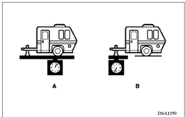
Never exceed the maximum trailer weight (A), maximum tongue weight (B), Gross Vehicle Weight Rating (GVWR) and Gross Axle Weight Rating (GAWR).
FOR PLEASANT DRIVING
CONTENTS
■ Sun visors....207
□ To adjust the sun visor position ..... 2 0 7
□ Vanity mirror....208
■ Accessory socket 209
■ Cup holder 210
■ Accessory boxes 211
□Glove compartment....212
□ Center console with lid. 2 1 3
□ Trunk net (if so equipped) ..... 2 1 3
Electronic digital clock....2 1 4
□ Clock setting procedure ..... 2 1 4
■ General information about your radio ..... 2 1 4
□ Signal transmission....2 1 5
□ Weak reception (fading) .....215
□ Reflections. 215
□ Cross modulation. 216
□ FM stereo reception ..... 2 1 6
□ Causes of disturbances....2 1 6
■ Whip antenna ..... 2 1 7
■ AM Stereo & FM Stereo Radio With Graphic Equalizer, Cassette Tape Player And CD Player (if so equipped) 217
□ Operating Instructions - Radio Mode .....217
□ Power Switch, Volume Control .....218
□ Seek Button (Radio Mode)....2 1 8
□ Tuning....2 1 8
□ Balance 218
204 FOR PLEASANT DRIVING
□Fade 218
□ Graphic Equalizer....218
□ AM/FM Selection....2 1 8
□ Scan Button....2 1 8
□ To Set The Radio Pushbutton Memory ..... 2 1 9
□ General Information....219
□ To Change From Clock To Radio Mode ..... 2 1 9
□ Tape Player Operation....2 1 9
□ Seek Button....2 2 0
□ Fast Forward (FF) 2 2 0
□ Rewind (RW) 2 2 0
□ Tape Eject....2 2 0
□ Scan Button....2 2 0
□ Changing Tape Direction ..... 2 2 0
□ Metal Tape Selection....2 2 0
□ Pinch Roller Release....2 2 0
□ Noise Reduction....2 2 1
□ Operation Instructions—CD Player ..... 2 2 1
□ Inserting The Compact Disc ..... 2 2 1
□ Seek Button....2 2 1
□ EJT CD (Eject) Button ..... 2 2 1
□FF/Tune/RW Button 221
□ Program Button 4 (Random Play) ..... 2 2 2
□ Tape /CD Button....2 2 2
□ Time Button 2 2 2
□ Scan Button....2 2 2
Cassette Tape And Player Maintenance ..... 2 2 2
AM/FM Stereo Radio With 4 Disc CD Changer (if so equipped) 2 2 3
□ Operating Instructions - Radio Mode ..... 2 2 3
□ Power Switch, Volume Control ..... 2 2 3
□ Seek Button (Radio Mode)....2 2 4
FOR PLEASANT DRIVING 205
□ Tuning....2 2 4
□ Balance....2 2 4
□Fade 224
□ Tone Control....2 2 4
□ MODE Selection....2 2 4
□ PTY (Program Type) Selection ..... 2 2 4
□ Scan Button 2 2 4
□ To Set The Pushbutton Memory ..... 2 2 5
□ To Change From Clock To Radio Mode ..... 2 2 5
□ General Information....2 2 5
□ Operating Instructions — CD Changer ..... 2 2 5
□ Inserting the Compact Disc....2 2 5
□ Seek Button....2 2 6
□ FF /Tune/ RW Button....2 2 6
□ Random Play....2 2 6
□ Radio/CD Button....2 2 6
□ Time Button 2 2 6
□ Scan Button....2 2 6
□ Loading The CD Changer ..... 2 2 6
□ Playing Discs....2 2 7
□ Removing Discs From The CD Changer ..... 2 2 7
■ Steering wheel remote control switches (if so equipped) 2 2 7
□ How to adjust the volume .....228
□ To listen to the audio system. . . . . . . . . . . . . . . . . 228
□ To listen to the radio .....228
□ Automatic tuning the radio....228
□ To select the preset memory ..... 2 2 8
□ To listen to a tape .....229
□ To listen to a CD .....229
□Handling of compact discs 230
■ Radio operation and cellular phones ..... 2 3 2
206 FOR PLEASANT DRIVING
■ Vents. 233
□ Air flow rate and direction adjustments .....233
■ Air conditioning 234
□ Control panel....2 3 4
□ Changing the blower speed. 235
□ Changing the temperature....235
□ Changing mode selection....236
□ Changing air selection....240
□ Air conditioning switch ..... 2 4 1
□ How to use the controls ..... 2 4 2
□ Defrosting or defogging of the windshield and door windows. 242
☐ Important operation tips for air conditioning . .245
□ Air conditioning system refrigerant and lubricant recommendations. 245
□ During a long period of disuse ..... 2 4 6
■ Installation of accessories ..... 2 4 6
SUN VISORS
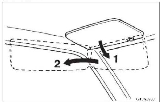
- To reduce front glare.
- To reduce side glare.
To adjust the sun visor position
- Remove the holder (A) from the hook (B), then move the sunvisor to the window.
- Slide the sun visor and adjust the position.
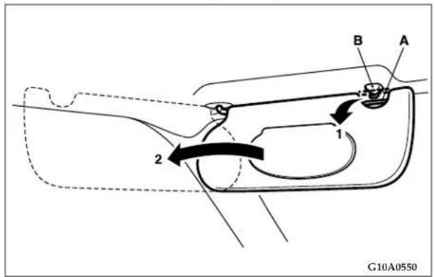
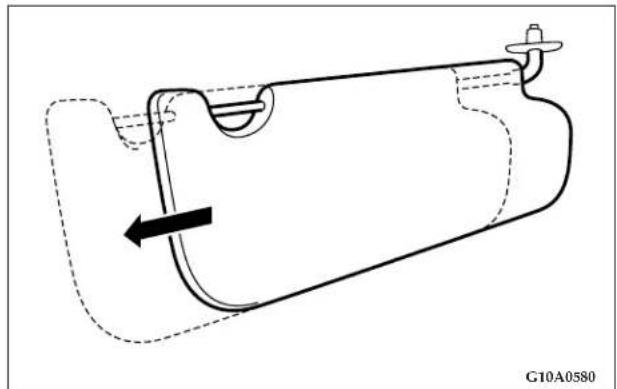
natural_image
Technical line drawing of a mechanical component with dashed outline and arrow indicating direction (no text or symbols)WARNING!
- Do not attempt to adjust the sun visor while driving. This can be dangerous.
Vanity mirror
A vanity mirror is on the back of the sun visor.
Type 1
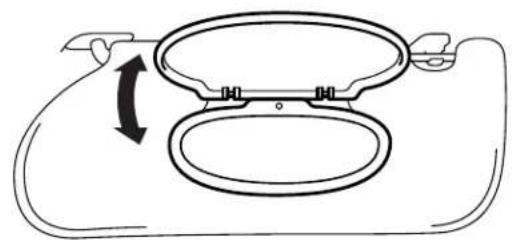
natural_image
Diagram of a car hood with a double bottom opening and directional arrow indicating rotation (no text or symbols)G13A0850
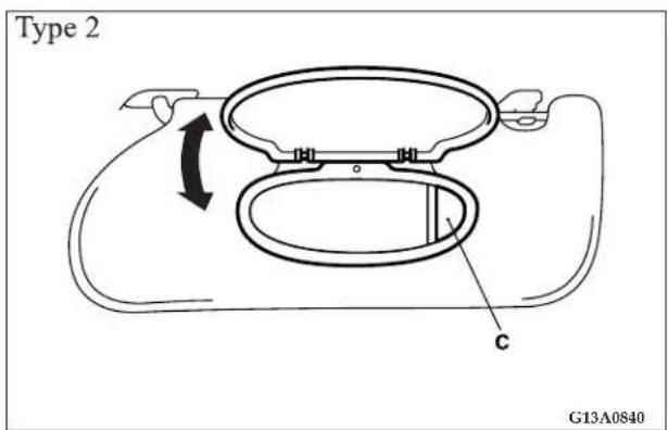
FOR PLEASANT DRIVING 209
ACCESSORY SOCKET
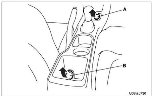
Two accessory sockets are provided in the center console. To use a "plug-in" type accessory, insert it in the socket.
The accessory socket (A) can be operated when the ignition key is in the "ON" or "ACC" positions. This socket can also be used for a lighter when an optional smokers kit is ordered from your dealer.
The accessory socket (B) is a direct feed from the battery so it can be operated whether the ignition is ON or OFF.
CAUTION!
- Be sure to use a "plug-in" type accessory operating on 12V and at 120W or less. Extended use of electronic equipment with the engine off may run down the battery.
- When the accessory socket is not in use, be sure to close the socket cap. This will prevent the socket from becoming clogged and short circuiting.
- Many accessories that can be plugged in draw power from the vehicle's battery, even when not in use (i.e., cellular phones, etc.). Eventually, if plugged in long enough, the vehicle's battery will discharge sufficiently to degrade battery life and/or prevent engine starting.
- Accessories that draw higher power (i.e., coolers, vacuum cleaners, lights, etc.) will degrade the battery even more quickly. Only use these intermittently and with greater caution.
- After the use of high power draw accessories, or long periods of the vehicle not being started (with accessories still plugged in), the vehicle must be driven a sufficient length of time to allow the generator to recharge the vehicle's battery.
CUP HOLDER
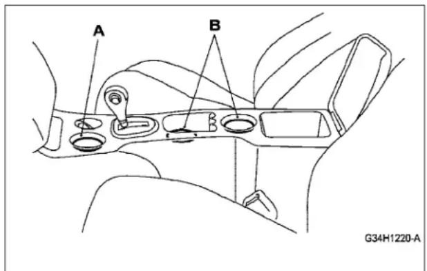
FRONT SEAT
The front holder (A) can be used to accept an ash receiver when an optional smokers kit is purchased from your dealer. The rear holders (B) are provided for use as cupholders.
CAUTION!
Do not drink beverages while driving the vehicle; doing so could distract you and result in an accident.
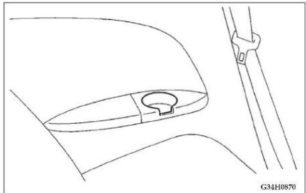
natural_image
Technical line drawing of a mechanical component with a curved base and mounting bracket (no text or symbols)REAR SEAT
Cup holders are provided at each side for the rear passengers.
ACCESSORY BOXES
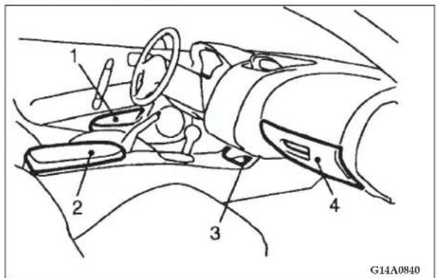
Convenient storage space is located throughout the vehicle.
- Door pockets
- Center console
- Center accessory box
- Glove compartment
212 FOR PLEASANT DRIVING
Glove compartment
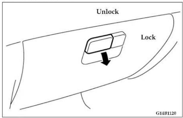
To open the glove compartment, pull the lever.
WARNING!
An open glove compartment door can result in serious injury to the front passenger in an accident, even if the passenger is wearing the seat belt. Always keep the glove compartment door closed when driving.
NOTE: If the glove compartment is opened, the glove compartment light illuminates.
Center console with lid
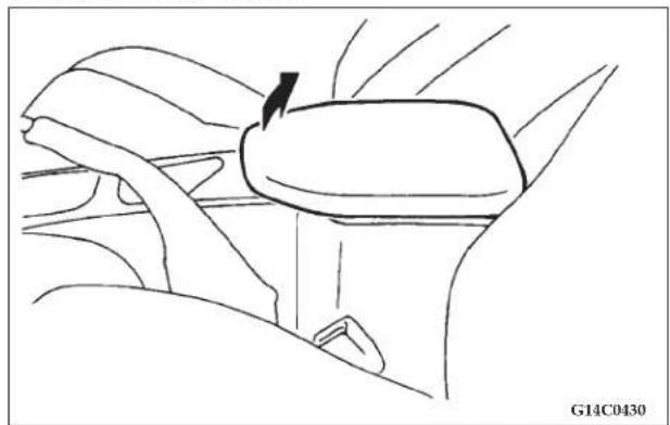
natural_image
Line drawing of a car seatbelt mechanism (no text or symbols)Small articles can be stored in center console.
To open the center console, pull up on the front of the lid.
Trunk net (if so equipped)
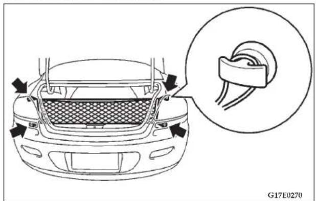
natural_image
Line drawing of a car front bumper with a magnified inset showing the rear wheel assembly (no text or symbols)Attach the net to hooks according to the illustration. Keep the net stored in the trunk so it can be used at any time.
214 FOR PLEASANT DRIVING
ELECTRONIC DIGITAL CLOCK
The clock and radio each use the display panel built into the radio. A digital readout indicates the time in hours and minutes whenever the ignition switch is in the ON or ACC position.
Clock setting procedure
-
Using the point of a ballpoint pen or similar object, press either the hour (H) or minute (M) buttons on the radio. The time setting will increase each time you press the button.
-
Press any other button to exit from the clock setting mode.
GENERAL INFORMATION ABOUT YOUR RADIO
FM AM
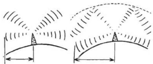
natural_image
Diagram showing two curved arch structures with directional arrows and wave patterns, no text or symbols present25 to 40 mile radius
(40 to 64 Km)
100 mile radius
(160 Km)
H12G0010
A vehicle is not an ideal place to listen to the radio, because the vehicle moves, and reception conditions are constantly changing. Buildings, terrain, signal distance and noise from other vehicles are all working against good reception.
Please read the following information regarding radio reception, especially those regarding stereo transmission.
Signal transmission
FM signals do not follow the earth's surface nor are they reflected by the upper atmosphere. For this reason, FM broadcasts cannot be received over long distances.
AM signals follow the earth's surface and are reflected by the upper atmosphere. For this reason, AM broadcasts can be received over longer distances.
Weak reception (fading)
Because of the limited range of FM transmissions and the way FM waves spread, fading usually occurs with FM reception.
When the broadcast is blocked by mountains or similar obstructions, reception disturbance may result.
Reflections
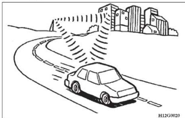
natural_image
Line drawing of a car driving on a curved road with buildings in the background (no text or symbols)The reason why one can hear FM but not AM in parking garages, under bridges etc., is that FM signals unlike AM signals, are reflected by solid objects such as buildings, etc.
Because FM signals are easily reflected by buildings, this can also cause reception disturbances.
216 FOR PLEASANT DRIVING
The direct signal from the broadcast station reaches the antenna slightly before the reflected signal. This time difference may cause some reception disturbance or flutter.
This typically occurs in urban areas.
Cross modulation
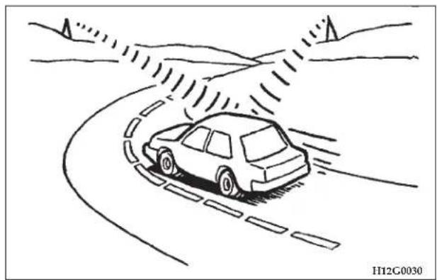
natural_image
Line drawing of a car driving on a curved road with motion trails, no text or symbols presentIf one listens to a weak station and is in the vicinity of another strong station, both stations might be received simultaneously.
FM stereo reception
Stereo reception requires a very high broadcast signal quality. This means that disturbances mentioned previously become more marked and the reception range is somewhat diminished during stereo reception.
Causes of disturbances
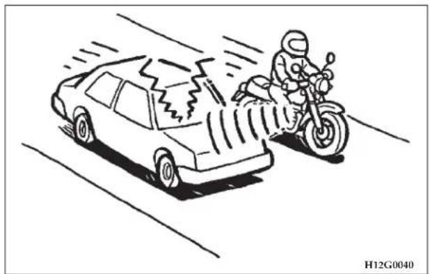
natural_image
Cartoon illustration of a car speeding past a motorcyclist on a road (no text or symbols)FM can be affected by electrical systems of vehicles in the vicinity, especially those without electronic noise suppression for the ignition system. The disturbance is even greater if the station is weak or poorly tuned.
FM reception is not as sensitive to electrical disturbances as AM. AM reception is sensitive to electrical disturbances such as power lines, lightning and other types of similar electrical phenomena.
WHIP ANTENNA
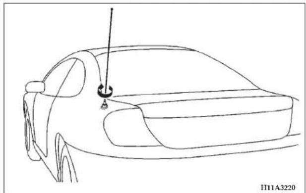
natural_image
Line drawing of a car's front view with antenna and suspension (no text or symbols)To remove the whip antenna, turn it counterclockwise.
| CAUTION! |
| It is recommended to remove the whip antenna before going into an automatic vehicle wash or passing under places with a low height clearance. |
AM STEREO & FM STEREO RADIO WITH GRAPHIC EQUALIZER, CASSETTE TAPE PLAYER AND CD PLAYER (IF SO EQUIPPED)
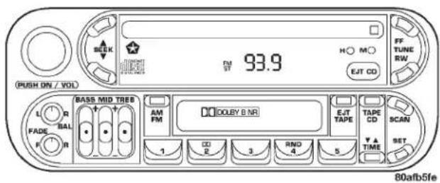
Operating Instructions - Radio Mode
NOTE: Power to operate the radio is supplied through the ignition switch. It must be in the ON or ACC position to operate the radio.
218 FOR PLEASANT DRIVING
Power Switch, Volume Control
Press the ON/VOL control to turn the radio on. Turn the volume control clockwise to increase the volume.
Seek Button (Radio Mode)
Press and release the Seek button to search for the next station in either the AM or FM mode. Press the top of the button to seek up and the bottom to seek down. The radio will remain tuned to the new station until you make another selection. Holding the button in will bypass stations without stopping until you release it.
Tuning
Press the TUNE control up or down to increase or decrease the frequency. If you press and hold the button, the radio will continue to tune until you release the button. The frequency will be displayed and continuously updated while the button is pressed.
Balance
The Balance control adjusts the left-to-right speaker balance. Push in the button and it will pop out. Adjust the balance and push the button back in.
Fade
The Fade control provides for balance between the front and rear speakers. Push in the button and it will pop out. Adjust the balance and push the button back in.
Graphic Equalizer
The graphic equalizer has 3 separate bands. Each is controlled by a slider control with a detent at the mid position. Moving a control up or down increases or decreases amplification of the band.
AM/FM Selection
Press the AM/FM button to change from AM to FM. The operating mode will be displayed next to the station frequency. The display will show ST when a stereo station is received.
Scan Button
Pressing the SCAN button causes the tuner to search for the next station, in either AM or FM, pausing for 5 seconds at each listenable station before continuing to the next.
Pressing the AM/FM button continues the search in the alternate frequency band.
To stop the search, press SCAN a second time.
To Set The Radio Pushbutton Memory
When you are receiving a station that you wish to commit to push-button memory, press the SET button. SET 1 will show in the display window. Select the push-button you wish to lock onto this station and press and release that button. If a station is not selected within 5 seconds after pressing the SET button, the station will continue to play but will not be locked into push-button memory.
You may add a second station to each push-button by repeating the above procedure with this exception: Press the SET button twice and SET 2 will show in the display window. Each button can be set for SET 1 and SET 2 in both AM and FM. This allows a total of 10 AM and 10 FM stations to be locked into memory. You can recall the stations stored in SET 2 memory by pressing the push-button twice.
General Information
This radio complies with Part 15 of FCC rules and with RS-210 of Industry Canada. Operation is subject to the following conditions:
- This device may not cause harmful interference,
- This device must accept any interference received, including interference that may cause undesired operation.
NOTE: Changes or modifications not expressively approved by the party responsible for compliance could void the user's authority to operate the equipment.
To Change From Clock To Radio Mode
Press the Time button to change the display between radio frequency and time.
Tape Player Operation
Insert the cassette with the exposed tape side toward the right and the mechanical action of the player will gently pull the cassette into the play position.
NOTE: When subjected to extremely cold temperatures, the tape mechanism may require a few minutes to warm up for proper operation. Sometimes poor playback may be experienced due to a defective cassette tape. Clean and demagnetize the tape heads at least twice a year.
220 FOR PLEASANT DRIVING
Seek Button
Press the SEEK button up for the next selection on the tape and down to return to the beginning of the current selection.
Press the SEEK button up or down to move the track number to skip forward or backward 1 to 6 selections. Press the SEEK button once to move 1 selection, twice to move 2 selections, etc.
Fast Forward (FF)
Press the FF button up momentarily to advance the tape in the direction that it is playing. The tape will advance until the button is pressed again or the end of the tape is reached. At the end of the tape, the tape will play in the opposite direction.
Rewind (RW)
Press the RW button momentarily to reverse the tape direction. The tape will reverse until the button is pressed again or until the end of the tape is reached. At the end of the tape, the tape will play in the opposite direction.
Tape Eject
Press the EJT Tape button and the cassette will disengage and eject from the radio.
Scan Button
Press this button to play 10 seconds of each selection. Press the scan button a second time to cancel the feature.
Changing Tape Direction
If you wish to change the direction of tape travel (side being played), press the TIME button. The lighted arrow in the display window will show the new direction.
Metal Tape Selection
If a standard metal tape is inserted into the player, the player will automatically select the correct equalization and the 70 symbol will appear in the display window.
Pinch Roller Release
If ignition power or the radio ON/OFF switch are turned off, the pinch roller will automatically retract to protect the tape from any damage. When power is restored to the tape player, the pinch roller will automatically reengage and the tape will resume play.
Noise Reduction
The Dolby noise reduction system* is on whenever the tape player is on, but may be switched off.
To turn off the Dolby noise reduction system: Press the NR button (button 2) after you insert the tape. The NR light in the display will go off when the Dolby NR System is off. The Dolby NR System is automatically reactivated each time a tape is inserted.
*Dolby noise reduction manufactured under license from Dolby Laboratories Licensing Corporation. "Dolby" and the double-D symbol are trademarks of Dolby Laboratories.
Operation Instructions — CD Player
NOTE: The ignition switch must be in the ON or ACC position and the volume control ON before the CD player will operate.
Inserting The Compact Disc
You may either insert or eject a disc with the radio OFF.
If you insert a disc with the ignition ON and the radio OFF, the display will show the CD symbol then the time of day will be displayed.
If the volume control is ON, the unit will switch from radio to CD mode and begin to play when you insert the disc. The display will show the track number and index time in minutes and seconds. Play will begin at the start of track 1.
Seek Button
Press the top of the SEEK button for the next selection on the CD. Press the bottom of the button to return to the beginning of the current selection, or return to the beginning of the previous selection if the tape is within the first 10 seconds of the current selection.
EJT CD (Eject) Button
Press this button and the disc will unload and move to the entrance for easy removal. The unit will switch to the radio mode.
If you do not remove the disc within 15 seconds, it will be reloaded. The radio will remain in the Radio mode.
The disc can be ejected with the radio OFF.
FF/TUNE/RW Button
Press the FF (Fast Forward) button and the CD player will fast forward through the tracks until the button is
222 FOR PLEASANT DRIVING
released. Press the RW (Rewind) button and the CD player will reverse through the tracks until the button is released.
Program Button 4 (Random Play)
Press this button while the CD is playing to activate Random Play. This feature plays the selections on the compact disc in random order to provide an interesting change of pace.
Press the SEEK UP button to move to the next randomly selected track.
Press button 4 a second time to stop Random Play.
Tape /CD Button
Press this button to select between CD player and Tape player.
Time Button
Press this button to change the display from elapsed CD playing time to time of day.
Scan Button
Press this button to play the first 10 seconds of each track. To stop the scan function, press the button a second time.
CASSETTE TAPE AND PLAYER MAINTENANCE
To keep the cassette tapes and player in good condition, take the following precautions:
- Do not use cassette tapes longer than C-90; otherwise, sound quality and tape durability will be greatly diminished.
- Keep the cassette tape in its case to protect from slackness and dust when it is not in use.
- Keep the cassette tape away from direct sunlight, heat and magnetic fields such as the radio speakers.
- Before inserting a tape, make sure that the label is adhering flatly to the cassette.
- A loose tape should be corrected before use. To rewind a loose tape, insert the eraser end of a pencil into the tape drive gear and twist the pencil in the required directions.
Maintain your cassette tape player. The head and capstan shaft in the cassette player can pick up dirt or tape deposits each time a cassette is played. The result of deposits on the capstan shaft may cause the tape to wrap around and become lodged in the tape transport. The other adverse condition is low or "muddy" sound from one or both channels, as if the treble tone control were turned all the way down. To prevent this, you should periodically clean the head with a commercially available WET cleaning cassette.
As preventive maintenance, clean the head about every 30 hours of use. If you wait until the head becomes very dirty (noticeably poor sound), it may not be possible to remove all deposits with a simple WET cleaning cassette.
AM/FM STEREO RADIO WITH 4 DISC CD CHANGER (IF SO EQUIPPED)
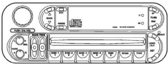
80f62197
Operating Instructions - Radio Mode
NOTE: Power to operate the radio is supplied through the ignition switch. It must be in the ON or ACC position to operate the radio.
Power Switch, Volume Control
Press the ON/VOL control to turn the radio on. Turn the volume control clockwise to increase the volume.
224 FOR PLEASANT DRIVING
Seek Button (Radio Mode)
Press and release the Seek button to search for the next station in either the AM or FM mode. Press the top of the button to seek up and the bottom to seek down. The radio will remain tuned to the new station until you make another selection. Holding the button in will bypass stations without stopping until you release it.
Tuning
Press the TUNE control up or down to increase or decrease the frequency. If you press and hold the button, the radio will continue to tune until you release the button. The frequency will be displayed and continuously updated while the button is pressed.
Balance
The Balance control adjusts the left-to-right speaker balance. Push in the button and it will pop out. Adjust the balance and push the button back in.
Fade
The Fade control provides for balance between the front and rear speakers. Push in the button and it will pop out. Adjust the balance and push the button back in.
Tone Control
The unit has 2 separate controls for bass and treble. Each is controlled by a slider control with a detent at the mid position. Moving a control up or down increases or decreases amplification of the band.
MODE Selection
Press the MODE button to change from AM, FM to CD changer and Sirius (Satellite radio) – if equipped. A CD may remain in the player while in the Satellite mode. The operating mode will be displayed next to the station frequency. The display will show ST when a stereo station is received.
PTY (Program Type) Selection
Displays program type in Satellite radio (if equipped) mode only.
Scan Button
Pressing the SCAN button causes the tuner to search for the next station, in either AM or FM, pausing for 5 seconds at each listenable station before continuing to the next. To stop the search, press SCAN a second time.
To Set The Pushbutton Memory
When you are receiving a station that you wish to commit to push-button memory, press the SET button. SET 1 will show in the display window. Select the push-button you wish to lock onto this station and press and release that button. If a station is not selected within 5 seconds after pressing the SET button, the station will continue to play but will not be locked into push-button memory.
You may add a second station to each push-button by repeating the above procedure with this exception: Press the SET button twice and SET 2 will show in the display window. Each button can be set for SET 1 and SET 2 in both AM and FM. This allows a total of 10 AM and 10 FM stations to be locked into memory. You can recall the stations stored in SET 2 memory by pressing the push-button twice.
To Change From Clock To Radio Mode
Press the time button to change the display between radio frequency and time.
General Information
This radio complies with Part 15 of FCC rules and with RS-210 of Industry Canada. Operation is subject to the following conditions:
- This device may not cause harmful interference,
- This device must accept any interference received, including interference that may cause undesired operation.
NOTE: Changes or modifications not expressively approved by the party responsible for compliance could void the user's authority to operate the equipment.
Operating Instructions — CD Changer
NOTE: The ignition switch must be in the ON or ACC position and the volume control ON before the CD player will operate.
Inserting the Compact Disc
You may either insert or eject a disc with the radio OFF. If you insert a disc with the ignition ON and the radio OFF the time of day will be displayed. If the volume control is ON, the unit will switch from radio to CD mode and begin to play when you insert the disc. The display
226 FOR PLEASANT DRIVING
will show the track number and index time in minutes and seconds. Play will begin at the start of track 1.
Seek Button
Press the top of the SEEK button for the next selection on the CD. Press the bottom of the button to return to the beginning of the current selection.
FF /TUNE/ RW Button
Press the FF (Fast Forward) button and the CD player will fast forward through the tracks until the button is released.
Random Play
Press the button while the CD is playing to activate Random Play. This feature plays the selections on the compact disc in random order to provide an interesting change of pace. The CD changer stays in the random mode when changing to the next disc.
NOTE: The changer will not random play between discs.
Press the top of the SEEK button once to move to the next randomly selected track. Press the bottom of the SEEK button to go back to the beginning of the track. Press button for a second time to stop Random Play.
Radio/CD Button
Press this button to select between CD player and radio.
Time Button
Press this button to change the display from elapsed CD playing time to time of the day.
Scan Button
Press this button to play the first 10 seconds of each track. To stop the scan function, press the button a second time.
Loading the CD Changer
The CD changer has one load/eject button located on the right side of the faceplate, and 4 disc position buttons.
- Select the desired disc position.
- Wait for the green READY light to stop flashing.
- Gently insert the CD at a slight downward angle.
- Press the next disc position and proceed to load additional CD's.
Playing Discs
The radio display indicates the CD number (the slot where the CD is loaded), and the current track being played at the time.
If more than one CD is loaded in the CD changer, it automatically plays the next CD after playing the last track of the current CD. If there is only one CD loaded, it will automatically return to the first track of the CD. To play any available disc select the desired disc position button.
Removing Discs from the CD Changer
- Press the load/eject button then press the desired disc position button to eject that CD.
- The display will flash the disc number that is being ejected.
- If the disc is not removed from the unit within 15 seconds the disc will automatically re-load.
STEERING WHEEL REMOTE CONTROL SWITCHES (IF SO EQUIPPED)
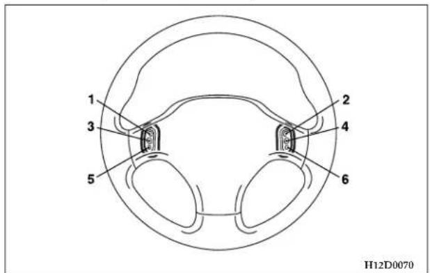
These switches can be used when the ignition switch is in the "ON" position.
- Seek up / Fast forward APS button / Track up button
- Volume up button
- Preset change / Disc up button
- Mode change button
228 FOR PLEASANT DRIVING
- Seek down / Rewind APS button / Track down button
- Volume down button
NOTE:
- Do not push two or more of the steering wheel remote control switches at the same time.
How to adjust the volume
Volume up button - 2
The volume will increase when this button is pressed.
Volume down button - 6
The volume will decrease when this button is pressed.
To listen to the audio system
Select the desired mode by lightly pressing the Mode change button (4). Every time the button is pressed, the mode can be changed.
Radio (AM) → Radio (FM) → Tape → CD
NOTE:
- Tape or CD mode cannot be selected unless a tape or CD is in the slot.
To listen to the radio
To select AM/FM mode
Mode change button - 4
Select the desired band (AM or FM) by pressing this button.
Automatic tuning the radio
Seek up button - 1
Seek down button - 5
After pressing these buttons, release the buttons, and reception of the selected station will begin.
To select the preset memory
Preset change button - 3
When the radio is on and this button is pressed, the preset station frequencies are sequentially selected each time the button is pressed; 1, 2, 3, 4, 5, 6, 7, 8, 9, 10, 1, 2 etc.
To listen to a tape
To operate the APS (Automatic Program Sensor) system
The start of each song on a prerecorded music tape can be found by using the Fast forward APS button (1) or Rewind APS button (5). As many as 7 programs can be skipped over in this manner.
Fast forward APS operation:
Press the APS button (1) to the number of songs you desire to skip over. The frequency-display window will display the number songs selected. The tape will be fast-forwarded to the start of the song, and playback will begin.
Rewind APS operation:
Press the APS button (5) to the number of the selection you desire to skip over including the one now being played. The frequency-display window will display the number of songs selected. The tape will be rewind to the start of the song, and playback will begin.
To listen to a CD
To select CD mode
Mode change button - 4
Select the desired mode (CD player mode or CD autochanger mode) by pressing this button.
To select a desired track
Track up button - 1
Press this button until the desired track is reached.
Track down button - 5
Press this button until the desired track is reached.
The frequency display window will display the number of tracks selected.
To select a desired disc (CD autochanger only)
Disc up button - 3
Press this button until the desired disc is reached.
230 FOR PLEASANT DRIVING
Handling of Compact Discs

H12F0180
(1) Use only the type of compact discs that have the mark shown in the illustration above. (Playback of CD-R discs may cause problems. CD-RW discs cannot be played).
(2) The use of special shaped, damaged compact discs (like cracked discs) or low-quality compact discs (like warped discs or burrs on the discs) such as those shown below will damage the CD player.
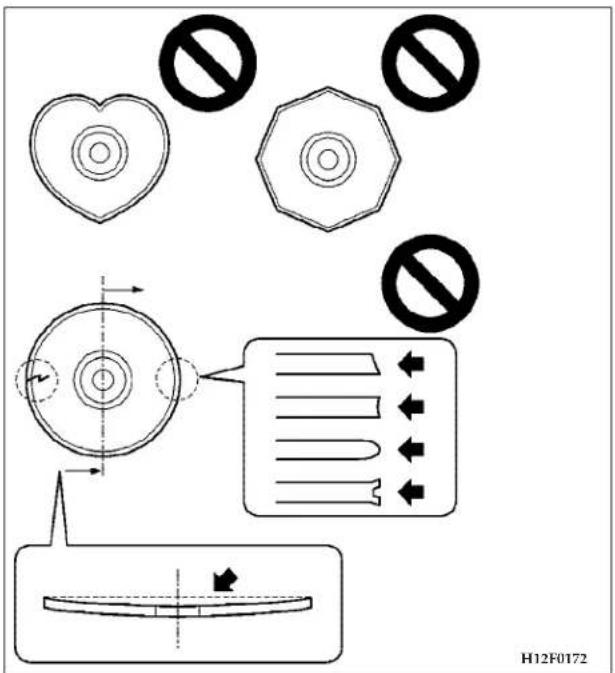
(3) In the following circumstances, moisture can form on compact discs and inside the audio system, preventing normal operation.
- When there is high humidity (for example, when it is raining).
- When the temperature suddenly rises, such as right after the heater is turned on in cold weather.
In this case, wait until the moisture has had time to dry out.
(4) When the CD player is subjected to violent vibrations, such as during off-road driving, the tracking may not work.
(5) When storing compact discs, always store them in their separate cases. Never place compact discs in direct sunlight, or in any place where the temperature or humidity is high.
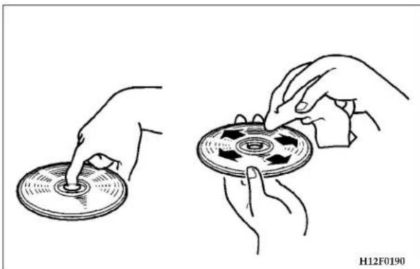
natural_image
Illustration of two hands inserting a disc into a circular base, showing mechanical components (no text or symbols)(6) Never touch the flat surface of the disc where there isn't a label. This will damage the disc surface and could affect the sound quality. When handling a compact disc, always hold it by the outer edge and the center hole.
(7) To clean a disc, use a soft, clean, dry cloth. Wipe directly from the center hole toward the outer edge.
232 FOR PLEASANT DRIVING
Do not wipe in a circle. Never use any chemicals such as benzine, paint thinner, a disc spray cleaner, or an anti-static agent on the disc.
(8) Do not use a ball point pen, felt pen, pencil, etc. to write on the label surface of the disc.
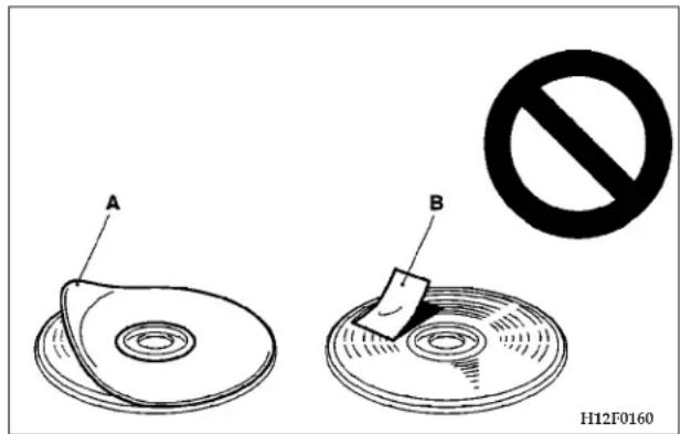
(9) Do not put additional labels (A) or stickers (B) on compact discs. Also, do not use any compact disc on which a label or sticker has started to peel off or any
compact disc that has stickiness or other contamination left by a peeled-off label, or sticker. If you use such a compact disc, the CD player may stop working properly and you may not be able to eject the compact disc.
CD player laser warning
WARNING!
Operating the CD player in a manner other than specifically instructed herein may result in hazardous radiation exposure.
Do not remove the cover and attempt to repair the CD player by yourself. There are no user serviceable parts inside. In case of malfunction, contact an authorized dealer.
Under certain conditions, the operation of a cellular phone in your vehicle can cause erratic or noisy performance from your radio. This condition may be lessened or eliminated by relocating the cellular phone antenna.
This condition is not harmful to the radio. If your radio performance does not satisfactorily "clear" by the repositioning of the antenna, it is recommended that the radio volume be turned down or off during cellular phone operation.
VENTS
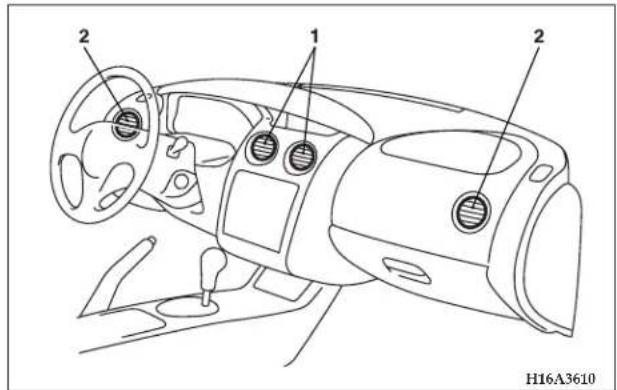
- Center vents
- Side vents
Air flow rate and direction adjustments
Center and side vents
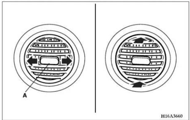
234 FOR PLEASANT DRIVING
Change the direction of the airflow from side to side by moving the knob (A). Change the vertical direction of the air flow up and down by pushing the top button edge of the vents.
NOTE: On rare occasions, air from the vents of an air-conditioned vehicle may look like fog. This is moist air suddenly cooled and there is no abnormality in the air conditioning system.
AIR CONDITIONING
Control panel
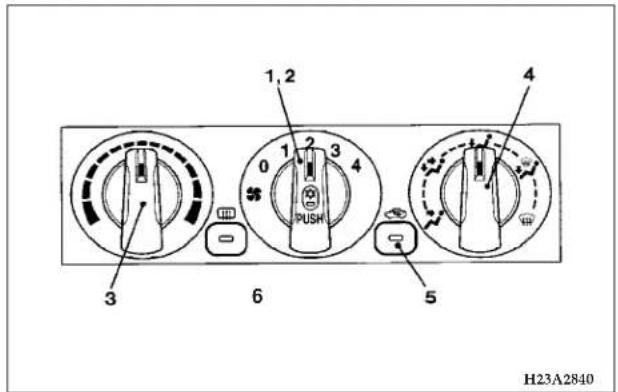
- Blower switch
- Air conditioning switch
- Temperature control dial
- Mode selection dial
- Air selection switch
Changing the blower speed
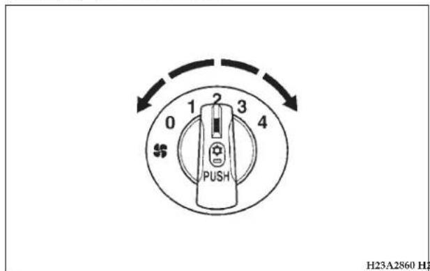
Changing the temperature
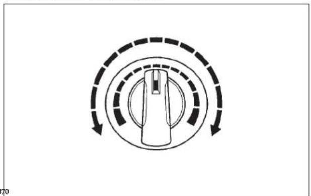
natural_image
Diagram of a rotary dial with concentric dashed arrows indicating clockwise motion (no text or symbols)The blower may be operated (when the ignition key is in the ON position) at 4 different speeds. Select the best speed to fit your needs. When the blower switch is set to the "O" position, all air conditioning functions will stop.
Select the desired temperature level by turning the temperature control dial either clockwise or counterclockwise. Turning the temperature control dial clockwise makes the air warmer.
NOTE: When the engine coolant temperature is low, the temperature of air introduced into the passenger compartment does not change even if the temperature control dial is moved to the high temperature side.
236 FOR PLEASANT DRIVING
Changing mode selection
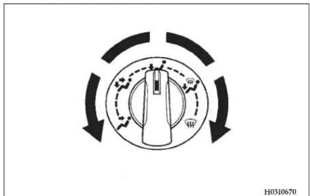
To change air flow to the different outlets, turn the mode selection dial to the desired position.
Face position
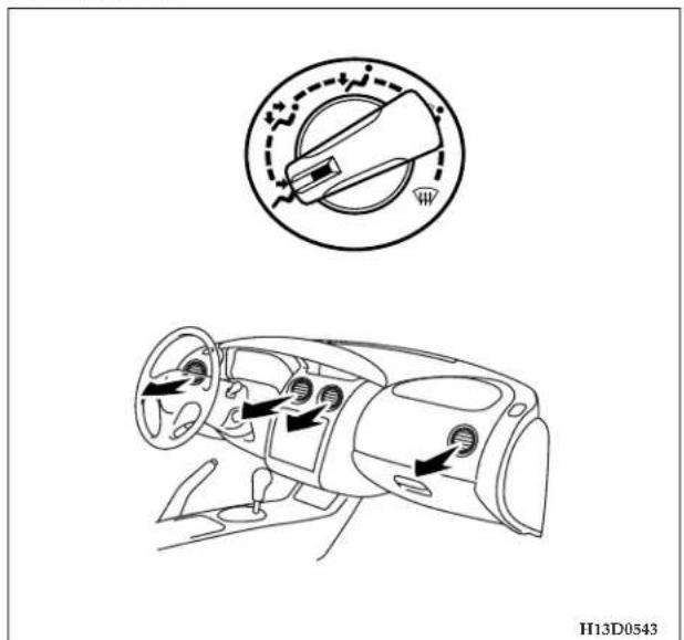
Air flows exclusively to the upper part of the passenger compartment.
Foot/face position
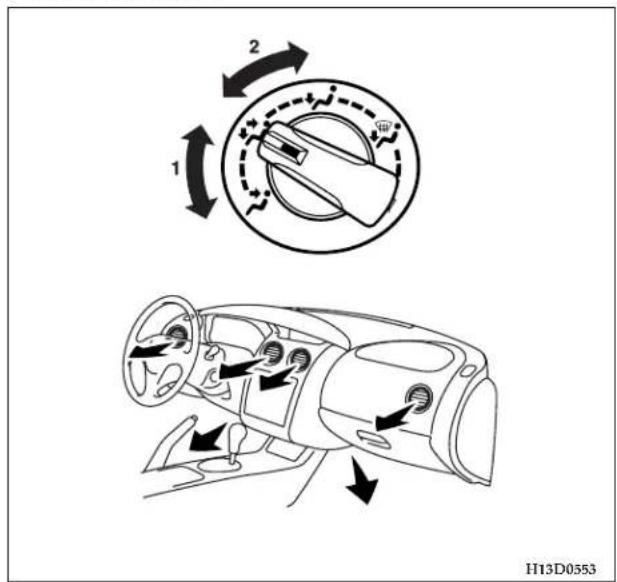
Air flows to the upper part of the passenger compartment and flows to the leg area.
NOTE: Air flows mostly to the upper part of the passenger compartment with the dial within position (1), and flows mostly to the leg area with the dial within position (2).
238 FOR PLEASANT DRIVING
Foot position
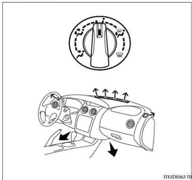
Foot/defroster position
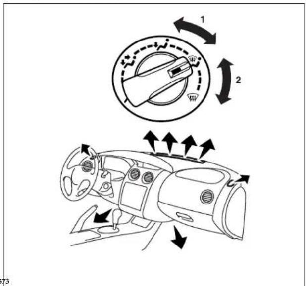
Air flows mainly to the leg area.
Air flows to the leg area, windshield, and door windows.
NOTE: Air flows mostly to the leg area with the dial within position (1), and flows mostly to the windshield with the dial within position (2).
Defroster position
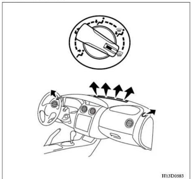
Air flows exclusively to the windshield and door windows.
240 FOR PLEASANT DRIVING
NOTE: When the mode selection dial is set to the “” or “” position, the air conditioning compressor will operate automatically. The outside air position will also be selected automatically. (In this case, the air conditioning indicator will not change.) This is done for optimum performance.
Changing air selection
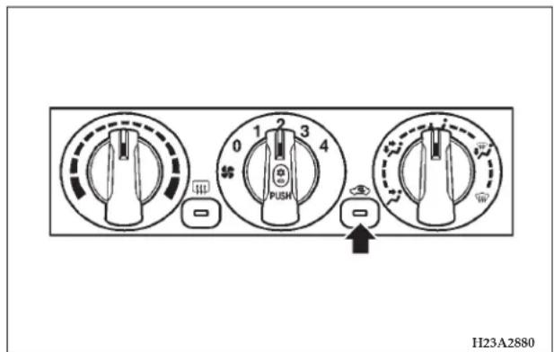
Normally use the "outside" position to keep the windshield and side windows clear and, also to quickly
remove fog or frost from the windshield.
When air conditioning is selected, the air selection will be controlled automatically for optimum performance.
When the air conditioning is turned off, the air selection will be set to the outside position.
The air selection indicator will show the selected position.
If desired, you can change the air selection. Every time the air selection switch is pushed, the mode for "outside" (Indicator OFF) and "recirculation" (Indicator ON) will alternate.
If high cooling performance is desired, or if the outside air is dusty or otherwise contaminated, use the “recirculation” position. Although, switch to the outside position periodically to prevent window fog up.
| CAUTION! |
| Using the “recirculation” position for extended time periods causes the windows to fog up. |
Air conditioning switch
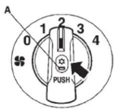
H23A3260
The air conditioning can be operated while the engine is running.
Push the switch and the air conditioning (cooling/dehumidifying function) will operate. When "ON", the operation indicator lamp (A) will illuminate.
Push the switch again and the air conditioning will stop.
CAUTION!
When using the air conditioning, the idle speed is slightly increased. Therefore, make sure your foot is firmly on the brake pedal when shifting the transmission to drive.
For the 3.0 liter engine model, if the air conditioning indicator (A) blinks, it is suspected that something is wrong with the air conditioning. Move the vehicle to a safe place and stop the engine. Then run the engine again and see the air conditioning indicator (A). If the indicator goes out, there is nothing wrong with the air conditioning. If it blinks again, have the system checked by the authorized dealer.
242 FOR PLEASANT DRIVING
How to use the controls
Heating
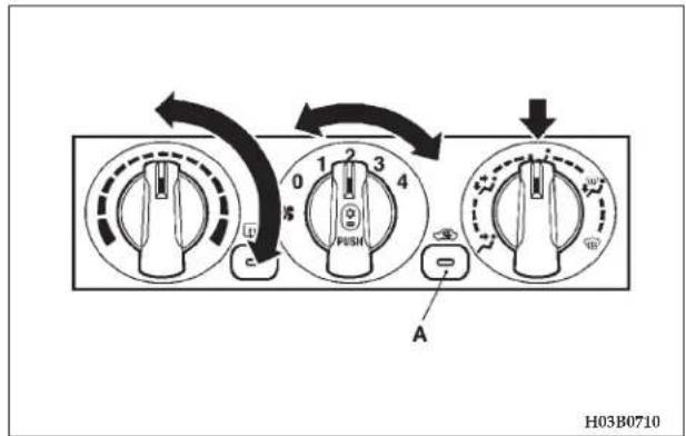
flowchart
graph TD
    A["0"] --> B["1"]
    B --> C["2"]
    C --> D["3"]
    D --> E["4"]
    E --> F["5"]
    F --> G["6"]
    G --> H["7"]
    H --> I["8"]
    I --> J["9"]
    J --> K["10"]
    K --> L["11"]
    L --> M["12"]
    M --> N["13"]
    N --> O["14"]
    O --> P["15"]
    P --> Q["16"]
    Q --> R["17"]
    R --> S["18"]
    S --> T["19"]
    T --> U["20"]
    U --> V["21"]
    V --> W["22"]
    W --> X["23"]
    X --> Y["24"]
    Y --> Z["25"]
Set the mode selection dial to the position shown in the illustration and set the air selection switch (A) to the "outside" position.
Adjust the temperature by turning the temperature control dial clockwise. Select the desired blower speed.
NOTE: When maximum heating is needed, set the blower speed to the fourth position.
Defrosting or defogging of the windshield and door windows
| CAUTION! |
| For safety, make sure you have a clear view through all windows before driving. |
To remove frost or fog from the windshield and door windows, use the mode selection dial (" " or "").
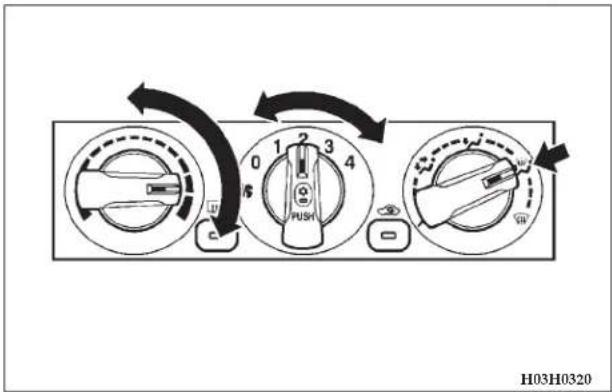
To keep the windshield and door windows defogged, and to keep leg area heated (when driving in rain or snow).
- Set the mode selection dial to the position.
- Adjust the blower to the desired speed.
- Set the desired temperature.
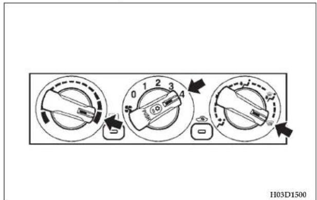
For quick defrosting
- Set the mode selection dial to the position.
- Adjust the blower to the maximum blower speed.
- Adjust the temperature control to the maximum temperature.
NOTE
- When the mode selection dial is set to the " " or " " position, the air conditioning compressor will operate automatically. The outside air position will also be selected automatically. (In this case, the air conditioning indicator will not change.)
- While in "☐" or "☐" position, you cannot turn the air conditioning off or select the recirculation position. This ensures that the windows will not fog up.
- To defog effectively, direct the air flow from the side vents toward the door windows.
- When defrosting, do not set the temperature control dial around the max. cool position. Cool air will blow against the window glass and fog it up.
244 FOR PLEASANT DRIVING
Combination of unheated air and heated air
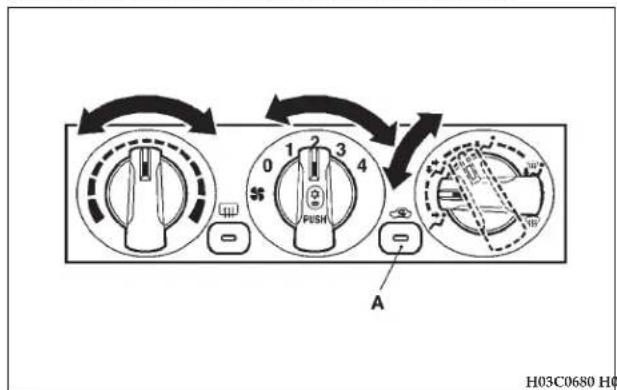
Cooling
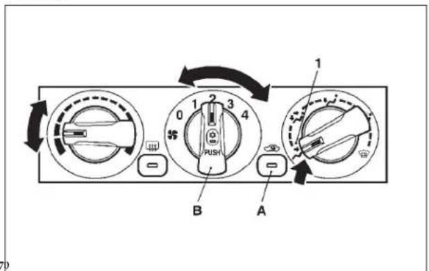
Set the mode selection dial to the position shown in the illustration and set the air selection switch (A) to the outside position.
The air will be directed to the leg area and the upper part of the passenger compartment. Select the desired blower speed.
Warm air flows to the leg area and unheated or slightly warm air flows to the upper part of the passenger compartment.
Set the mode selection dial to the “” position shown in the illustration.
Set the air selection switch (A) to the outside position and push the air conditioning switch (B).
- Setting for ordinary cooling
- Setting for cooling the leg area
Adjust the temperature by turning the temperature control dial clockwise or counterclockwise. Select the desired blower speed.
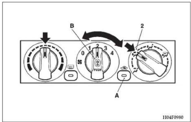
NOTE: If the outside air is dusty or otherwise contaminated, or if maximum cooling performance is desired, set air selection switch (A) to the recirculation position and the temperature control dial all the way to the left. Introduce outside air from time to time for proper ventilation.
Important operation tips for air conditioning
- Park the vehicle in the shade whenever possible. Parking under the hot sun makes the vehicle interior extremely hot, which requires more time to cool the interior. If it is necessary to park in the sun, open the windows for the first few minutes of air conditioning operation to expel hot air.
- Close the windows when the air conditioning is in use. The entry of outside air through open windows will reduce cooling efficiency.
- When operating the system, make sure the air intake, which is located in front of the windshield, is free of obstructions such as leaves. Leaves collected in the air-intake plenum may reduce air flow and plug the plenum water drains.
Air conditioning system refrigerant and lubricant recommendations
If the air conditioning seems less effective than usual, the cause might be a refrigerant leak.
Have the system inspected by your authorized dealer.
CAUTION!
The air conditioning system in your vehicle must be charged with the refrigerant HFC-134a and the lubricant SUN-PAG 56.
Use of any other refrigerant or lubricant will cause severe damage which will result in the need to replace your vehicle's entire air conditioning system. The release of refrigerant into the atmosphere is not recommended.
The new refrigerant (HFC-134a) in your vehicle is designed not to harm the earth's ozone layer. However, it may slightly contribute to global warming. It is recommended that the refrigerant be recovered and recycled for future use.
During a long period of disuse
The air conditioning should be operated for at least five minutes each a week, even in cold weather. This is to maintain lubrication of the compressor internal parts and maintain the air conditioning in the best operating condition.
INSTALLATION OF ACCESSORIES
CAUTION!
Before any electrical or electronic accessories are installed, consult an authorized dealer.
- Improper installation of an electrical or electronic accessory may cause a fire or electrical problem. It also could result in failure of warranty coverage under the new vehicle limited warranty.
- When using a communication system such as a cellular phone or a radio set inside the vehicle, be sure to install a separate external antenna. When a cellular phone or a radio set is used by using an internal antenna alone, it might cause failure to the vehicle's electrical system and could interfere with safe operation of the vehicle.
WARNING!
If you use a cellular phone while driving, keep your attention on your driving, in order to reduce risk of accidents.
VEHICLE CARE
CONTENTS
■ Cleaning the inside of your vehicle ..... 2 4 9
□ Plastic, vinyl leather, fabric, and flocked parts. .249
□Upholstery....249
□ Genuine leather (if so equipped) ..... 2 5 0
■ Cleaning the outside of your vehicle ..... 2 5 0
□ Foreign material. 250
□ Washing....251
□ During cold weather 252
□ Waxing your vehicle. 253
□Polishing your vehicle....254
□ Damaged paint 254
□ Cleaning plastic parts. 254
□ Chrome parts....255
□ Aluminum wheels (if so equipped) ..... 2 5 5
□ Window glass 255
□ Wiper blades ..... 2 5 5
□ Cleaning the sunroof (if so equipped) ..... 2 5 5
□ Engine compartment....255
248 VEHICLE CARE
In order to maintain the value and good looks of your vehicle, perform regular maintenance using proper materials and procedures.
Be sure to use only those materials and procedures that are in compliance with all local environmental pollution control regulations. Carefully select the materials to be used to be sure that they do not contain corrosives; if in doubt, contact an authorized dealer for assistance in the selection of these materials.
CAUTION!
Cleaning products can be dangerous. Some are poisonous. Others are highly flammable. Some are dangerous if you breathe their fumes in a closed space. When you use any product to clean your vehicle, be sure to follow the instructions printed on its container. Always open your vehicle doors or windows when you're cleaning the inside. Never use the following chemicals to clean your vehicle:
- Gasoline
• Carbon Tetrachloride - Benzine
- Naphtha
- Acetone
- Turpentine
- Paint Thinner
• Lacquer Thinner
• Nail Polish Remover
These can all be dangerous, and can damage your vehicle.
CLEANING THE INSIDE OF YOUR VEHICLE
After cleaning the inside of your vehicle with cleaner, wipe it dry in a shady, well ventilated area.
CAUTION!
Do not use organic substances (solvents, kerosene, alcohol, gasoline, etc.) or alkaline or acidic solutions. These chemicals can cause discoloring, staining or cracking of the surface. If you use cleaners or polishing agents, make sure their ingredients do not include the substances mentioned above.
NOTE: Always read the instructions on the cleaner label.
Plastic, vinyl leather, fabric, and flocked parts
-
Lightly wipe with a soft cloth soaked in a 3% solution of neutral detergent and water.
-
After using detergent, dip the cloth in fresh water and wring out well. Using this cloth, wipe off the detergent thoroughly.
NOTE: Cleaners, conditioners, and protectants containing silicons or waxes may cause annoying reflections and obscure vision.
Upholstery
- To maintain the value of your new vehicle, maintain the upholstery carefully and keep the interior clean. Use a vacuum cleaner and brush to clean the seats. If stained, vinyl and synthetic leather should be cleaned with an appropriate cleaner. Cloth fabrics can be cleaned with either upholstery cleaner or a 3% solution of neutral detergent in lukewarm water.
- Clean the carpeting with a vacuum cleaner and remove any stains with carpet cleaner. Oil and grease can be removed by lightly dabbing with a clean colorfast cloth and spot remover.
NOTE: If fuzzing is difficult to remove from the seat upholstery, draw a suitable defuzzing brush over the surface in one direction.
250 VEHICLE CARE
Genuine leather (if so equipped)
- Lightly wipe with a soft cloth soaked in a 5% solution of neutral detergent and water.
- Dip the cloth in fresh water and wring it out well. Using this cloth, wipe off the detergent thoroughly.
- Apply a leather protecting agent to the genuine leather surface.
NOTE
- If genuine leather is wet with water, wipe off the water as quickly as possible with a dry, soft cloth.
- Slight stains on genuine leather may be removed with a leather cleaner.
- The genuine leather surface may be damaged if a nylon brush is rubbed hard against it.
- Organic solvents such as benzine, alcohol, gasoline, acid or alkaline solvents may discolor the genuine leather surface and should not be used.
-
Dirty genuine leather seats may mildew. Be very careful about oil stains and remove them immediately.
-
The genuine leather surface may harden and shrink if it is exposed to the direct rays of the sun for long hours. When your vehicle is parked, place it in the shade as much as possible.
- When the temperature of the vehicle interior rises in the summer, vinyl products left on the genuine leather seat may deteriorate and stick to the seat.
CLEANING THE OUTSIDE OF YOUR VEHICLE
To protect your vehicle's outside finish, it is important that you wash it often and thoroughly. If desired, you may wax your vehicle by using an automobile wax.
Foreign material
Industrial fallout, road tar, bird droppings, tree sap, insect remains, sea water, and other foreign matter can damage the finish of your vehicle. Generally, the longer the foreign material remains in contact with the outside finish the more extensive the damage. Wash your vehicle as soon as possible if it becomes contaminated with foreign material.
Washing
Chemicals contained in the dirt and dust picked up from air, rain, snow, or road surface can damage the paint coat and body of your vehicle if left in prolonged contact. Frequent washing and waxing is the best way to protect your vehicle from this damage.
Do not wash the vehicle in direct sunlight. Park the vehicle in the shade and spray it with water to remove dust. Next, using an ample amount of clean water and a car washing mitt or sponge, wash the vehicle from top to bottom.
Use a mild vehicle washing soap. Rinse thoroughly and wipe dry with a chamois or soft cloth. After washing the vehicle, carefully clean the joints and flanges of the doors, hood, etc., where dirt is likely to remain.
CAUTION!
- When washing the under side of your vehicle, wear a pair of rubber gloves in order to protect your hands.
- Never spray or splash water on the electrical components in the engine compartment, as this may adversely affect the starting circuit. Exercise caution also when washing the underbody; be careful not to spray water into the engine compartment.
- Using an automatic car wash, pay attention to the following items, referring to the operation manual or consulting a car wash operator.
- The outside mirrors and the antenna are retracted.
CAUTION!
- Some types of washers (including coin-operated washers) apply high temperature and high pressure to the vehicle, which may cause heat distortion and damage to the resin parts of the vehicle body, leakage of water into the vehicle, etc. Therefore, be sure to observe the following.
- Maintain a good distance of approx. 16 in. (40 cm) or more between the vehicle body and the washing nozzle.
- When washing around the door glass, hold the nozzle at a distance of more than 40 in.(1m) and at right angles to the glass surface.
During cold weather
Salt and other chemicals that are spread on winter roads in some geographical areas can have a detrimental effect on the vehicle underbody. You should flush the underbody with a high pressure hose every time you wash the exterior of your vehicle.
Special care should be taken to remove mud or other debris which could trap and hold salt and moisture. After washing your vehicle, wipe off all water drops from the rubber parts around the doors to prevent the doors from freezing.
NOTE: When a door is frozen, opening it by force may tear or crack the rubber gasket installed around the door. Therefore, pour warm water to melt the ice. Be sure to wipe off water thoroughly after opening the door. To help prevent freezing of the weatherstripping on the doors, hood, etc., treat the rubber seal with a lubricant designed for rubber.
Waxing your vehicle
Wax your vehicle once or twice a year, or when painted surfaces do not shed water well.
Apply a small amount of wax to painted surfaces with a soft cloth. After the wax has dried, polish with a dry soft cloth.
Do not wax your vehicle in direct sunlight.
You should wax after the surfaces have cooled.
CAUTION!
- Waxes containing high abrasive compounds should not be used. Such waxes remove rust and stain effectively from the paintwork, but are harmful to the luster of the painted surface, since they also remove paint/clearcoat.
Further, they are detrimental to glossy surfaces such as the grille, garnish, moldings, etc.
- Do not use gasoline, kerosene, benzene or paint thinners to remove road tar or other contamination to the painted surface.
- Do not apply wax on the areas having black mat coating as it can cause uneven discoloration, patches, blurs, etc. If stained with wax, immediately wipe off with a soft cloth and warm water.
- Be careful when waxing the area around the sunroof opening, not to apply any wax on the weatherstrip (black rubber). If stained with wax, the weatherstrip cannot maintain a weatherproof seal with the sunroof.
254 VEHICLE CARE
Polishing your vehicle
If painted surfaces have been severely damaged and lost their original luster and color tone, polish the surface lightly with a fine polishing compound. Avoid limiting your polishing to the damaged surface only; polish a somewhat wider area, moving the polishing cloth in one direction. After polishing, flush the compound from the surface and apply a coat of wax to regain a beautiful luster.
Damaged paint
Small cracks and scratches in the paint coat should be touched up as soon as possible with touch-up paint to prevent corrosion.
Check body areas facing the road or the tires carefully for damage to the paint coat caused by flying stones, etc. The paint code number for your vehicle can be found on the vehicle information code plate in the engine compartment.
Cleaning plastic parts
Use a sponge or chamois.
If vehicle wax adheres on the plastic bumper or moldings, the surface may appear white in color. In this case, wipe it off using lukewarm water and a soft cloth or chamois.
CAUTION!
- Do not use a scrub brush or other hard tools as they may damage the plastic part surface.
- Do not use wax containing compound (polishing compound) which may damage the plastic part surface.
- Do not bring plastic parts into contact with brake fluids, engine oils, greases, thinner for painting, and sulfuric acid (battery electrolyte) which may stain, crack or discolor the plastic parts.
If they touch the plastic part, wipe them with a soft cloth, or chamois and an aqueous solution of neutral detergent. Then, immediately rinse the affected parts with water.
Chrome parts
To prevent spots and corrosion of chrome parts, wash with water, dry thoroughly, and apply a nonabrasive automotive wax. If the chrome is severely damaged or pitted use a commercially available chrome polish.
Aluminum wheels (if so equipped)
A protective coating is provided over aluminum wheels. Clean aluminum wheels with a cleaner designed for use on aluminum and apply an appropriate protection agent.
CAUTION!
- Do not use abrasive cleaners.
- Brushes may damage the aluminum wheel surface. Be sure to use a sponge, chamois, etc.
- Do not apply hot water directly from a steam cleaner to the wheel surface.
- Wheels exposed to sea water or road chemicals should be cleaned as soon as possible.
Window glass
The window glass can be cleaned using only a sponge and water. Glass cleaner can be used to remove wax, oil, grease, dead insects, etc. After washing the glass, wipe dry with a clean, dry, soft cloth.
Wiper blades
Use a soft cloth and glass cleaner to remove grease, dead insects, etc., from the wiper blades.
Replace the wiper blades when they no longer clean the windshield properly.
Cleaning the sunroof (if so equipped)
Clean the inside of the sunroof with a soft cloth. Hard deposits should be wiped away with a cloth dipped in warm, neutral detergent solution. Wipe away the solution with a sponge dipped in fresh water.
NOTE: The surface treatment on the inside of the glass may be removed if a hard cloth or organic solvent is used.
Engine compartment
Never spray or splash water on the electrical components in the engine compartment, as this may adversely affect the electrical circuits.
EMERGENCIES
CONTENTS
■ If the vehicle breaks down ..... 2 5 9
□ If the engine quits ..... 2 5 9
■ Operation under adverse driving conditions . . . 2 5 9
□ If your vehicle becomes stuck in sand, mud or snow....259
□Onawetroad....
□ On snowy or icy roads....261
■ Spare tire, jack and tool set storage ..... 2 6 2
□ Handling spare tire....2 6 2
□ Jack....263
■ Compact spare tire 263
■ Wheel covers (if so equipped) ..... 2 6 4
■ Jacking and tire changing 266
□ Jacking up the vehicle . . . . . . . . . . . . . . . . . . . . 2 6 6
■ Engine overheating ..... 2 7 4
■ Jump-starting the engine ..... 2 7 5
□ If your vehicle has anti-lock brakes . . . . . . . . 2 8 0
260 Towing 280
■ Fuses 282
□ Fuse block. 282
■ Fusible links 283
□ Fuse load capacities....283
■ Replacement of light bulbs....288
□ Bulb capacity. 288
258 EMERGENCIES
□ Headlights (Type 1)....290
□ Headlights (Type 2)....291
□ Adjustment of headlight aim. 293
□ Front turn signal and parking lights. . . . . . . . 2 9 3
□ Front side marker lights ..... 294
□ Front fog light 294
□ Rear combination lights ..... 296
□ High-mounted stop light ..... 298
□ License plate light....298
□ Dome light....299
IF THE VEHICLE BREAKS DOWN
If the vehicle breaks down on the road, move to the shoulder and activate the hazard warning flashers. If there is no shoulder, or the shoulder is not safe, drive in the right lane, slowly, with the hazard flashers activated, until you reach a safe place to stop. Keep the flashers activated.
If the engine quits
If the engine stops, power will be lost to the steering and brakes, making steering and braking difficult.
- The brake booster becomes inoperative and the brake pedal will be harder to push than usual.
- Since power steering system is not operative, the steering wheel will be stiff when turning. Turn the wheel with more effort than usual.
OPERATION UNDER ADVERSE DRIVING CONDITIONS
If your vehicle becomes stuck in sand, mud or snow
If the vehicle becomes stuck in snow, sand, or mud, it can often be moved by a rocking motion. Turn your steering wheel right and left to clear the area around the wheels. Move the gearshift lever or selector lever rhythmically between 1st and REVERSE position (with manual transaxle), "L" (Low) and "R" (REVERSE) position (with automatic transaxle), Autostick and "R" (REVERSE) position (with automatic transaxle), while applying slight pressure to the accelerator pedal.
Avoid racing the engine or spinning the wheels. Prolonged efforts to free a stuck vehicle may result in overheating and transaxle failure.
Allow the engine to idle for a few minutes to let the transaxle cool between rocking attempts.
If the vehicle remains stuck after several rocking attempts, seek other assistance.
WARNING!
When attempting to rock your vehicle out of a stuck position, be sure that the area around the vehicle is clear of people. The rocking motion may cause the vehicle to suddenly lurch forward or backward, causing injury to by-standers.
On a wet road
CAUTION!
- Avoid flooded roads. Water depth can be deceptive, and you could be seriously hurt by driving into flood water.
- When driving in rain, on water-covered roads, or through a vehicle wash, water could enter the brake drum linings or discs, resulting in temporarily ineffective brakes. In such cases, lightly depress the brake pedal to see if the brakes operate properly. If they do not, lightly depress the pedal several times while driving in order to dry the brake pads or linings, then check them again.
CAUTION!
- When driving in rain, a layer of water may form between the tires and the road surface (hydroplaning).
This reduces a tire's frictional resistance on the road, resulting in loss of steering stability and braking capability. When driving on a wet road, observe the following:
(a) Drive your vehicle at a safe speed.
(b) Do not drive on worn tires.
(c) Always maintain the specified tire inflation pressures.
On snowy or icy roads
- When driving on a road covered by snow or ice, it is recommended that you use snow tires.
CAUTION!
Tire chains are not recommended for your vehicle. The clearance between the chains and the body is small, and body damage may occur.
- Drive slowly. Avoid any sudden starts or stops, abrupt brake application or sharp cornering.
- Depressing the brake pedal during travel on snowy or icy roads may cause tire slippage and skidding. When a skid occurs, take your foot off the accelerator. Steer gently into the skid. Braking will differ, depending upon whether you have anti-lock brakes (ABS). If you do have ABS, brake by pressing the brake pedal firmly, and keeping it pressed. If you do not have ABS (vehicles without anti-lock braking system) pump the brake pedal with short rapid jabs, each time fully applying and fully releasing for greatest effect.
- Allow extra distance between your vehicle and the vehicle in front of you, and avoid sudden braking.
262 EMERGENCIES
SPARE TIRE, JACK AND TOOL SET STORAGE
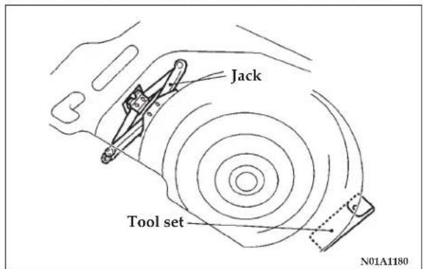
The spare tire, jack and tool set are stowed in the trunk.
Handling spare tire
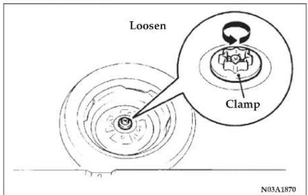
Remove the installation clamp to remove the spare tire. To install the spare tire, tighten the clamp firmly with your fingers until the spare tire has no more play.
Jack
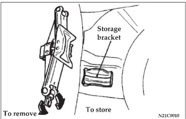
To remove
Turn the shaft end so that the jack contracts and detach it from the storage bracket.
To store
Turn the shaft end by hand to expand the jack until it is secured firmly in position.
COMPACT SPARE TIRE
The compact spare tire is designed to save space in the trunk and its lighter weight makes it easier to use if a flat tire occurs.
CAUTION!
- The tire pressure should be periodically checked and maintained at the specified pressure while the tire is stowed.
- Driving with an insufficient tire pressure can lead to an accident. If you have no choice but to drive with an insufficient tire pressure, keep your speed down and adjust to the specified pressure [60 psi (420 kPa)] as soon as possible.
- The compact spare should only be used temporarily and should be returned to the trunk and the original tire repaired or replaced as soon as possible. If your vehicle is equipped with aluminum type wheels, the wheel nuts for aluminum type wheels can be used temporarily on the compact spare tire wheel.
- Do not exceed 50 mph (80 km/h) while the compact spare tire is installed on the vehicle.
CAUTION!
- Avoid rapid starting and braking with a compact spare tire.
- Avoid driving through automatic vehicle washes and over obstacles that could possibly damage the vehicle's under-carriage. Because the tire is smaller than the original tire, vehicle ground clearance is slightly reduced.
- As the compact spare tire is specifically designed for your vehicle, it should not be used on any other vehicle.
- The compact spare tire should not be used on any other wheels, nor should standard tires, snow tires, wheel covers or trim rings be used with the compact spare wheel. If such use is attempted, damage to these items or other vehicle components may occur.
- Do not use snow chains with your compact spare tire. Because of the smaller tire size, a snow chain will not fit properly. This could cause damage to the vehicle and could result in loss of the chains.
- The compact spare tire pressure should be checked once a month while the tire is stowed.
WHEEL COVERS (IF SO EQUIPPED)
To remove
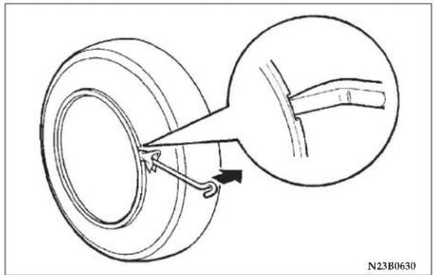
Wrap the tip of the bar with a cloth, insert it deeply into the notch provided in the wheel cover, and pry the cover away from the wheel.
Using the same procedure on the other side, work the wheel cover away from the wheel to remove it completely.
NOTE: The wheel cover is made of plastic; use caution when prying it off.
NOTE: Some styles of wheels will have bolt-on type wheel covers. To remove this style, remove the bolts that hold the cover to the wheel.
CAUTION!
Trying to simply remove the wheel cover with your bare hands may severely injure your fingers.
To install
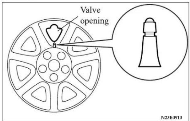
Align the air valve with the valve opening provided on the wheel cover.
Then pound around the outer edge of the wheel cover with your hand to secure it in place.
NOTE: The full wheel cover has its reverse side provided with a symbol mark to show the air valve location.
266 EMERGENCIES
Before installing the wheel cover to the wheel, make sure that the opening with the symbol mark is correctly aligned with the air valve.
JACKING AND TIRE CHANGING
If a tire must be changed, do so only after making sure the vehicle is stopped in a safe, flat location.
Jacking up the vehicle
-
Park the vehicle on level and stable ground.
-
Switch on the hazard warning flashers, set up a warning triangle, flashing signal light, etc., at an adequate distance from the vehicle, and have all passengers leave the vehicle. Turn the ignition key to the "LOCK" position.
-
Set the parking brake firmly, and move the gearshift lever (manual transaxle) to the "N" (Neutral) position or move the selector lever (automatic transaxle) to the "P" (PARK) position.
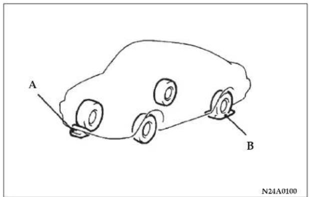
- Apply a chock or block (A) at the tire diagonally opposite the tire (B) to be changed.
NOTE: The chock shown is not supplied with the vehicle. It is recommended that you keep one in the vehicle for use if required.
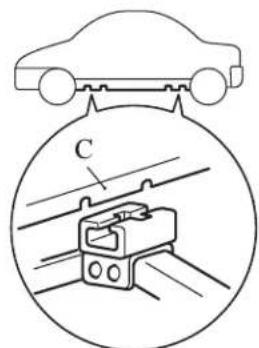
N22A1280
- Place the jack under one of the jacking points shown in the illustration. Use the jacking point closest to the tire being changed.
C = Jacking point
WARNING!
- Do not set the jack at any other position on the vehicle than those specified. If the jack is set at a wrong position, the body of the vehicle could be dented or the jack might fall over and cause personal injury.
- Avoid using the jack on tilted or soft surfaces. Otherwise, the jack might slip and cause personal injury. Always use the jack on a flat, hard surface. Before setting the jack, check to ensure that there is no sand or pebbles on the underside of the jack base.
268 EMERGENCIES
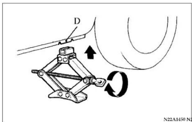
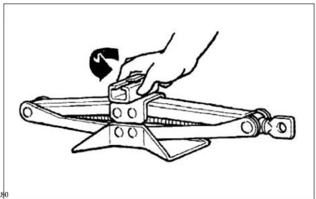
natural_image
Line drawing of a hand using a pliers to adjust a mechanical part (no text or symbols)- Rotate the jack by hand until the flange portion (D) fits in the groove at the top of the jack.
NOTE: Before use, turn the top of jack and set it as shown in the illustration.
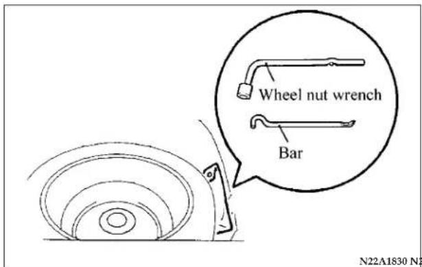
- Remove the wheel nut wrench and bar from the tool bag (located inside the trunk).
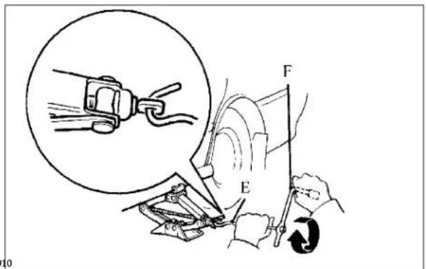
- Insert the bar (E) into the wheel nut wrench (F). Then attach the end of the bar to the jack end, as shown in the illustration.
Slowly rotate the wheel nut wrench until the tire is slightly raised off the ground surface.
WARNING!
- Before using the jack, chock or block the wheel that is tire diagonally opposite the jacking point.
- Stop jacking up the vehicle when the tire is raised off the ground. It is dangerous to raise the vehicle any higher.
- Do not get under the vehicle while using the jack.
- Avoid jarring the raised vehicle or leaving it supported on the jack for extended periods. Both are very dangerous.
- Do not use a jack other than the one provided with your vehicle.
- The jack should not be used for any purpose other than changing a tire.
- No one should stay in the vehicle while the jack is used.
- Do not start or run the engine while the vehicle is on the jack.
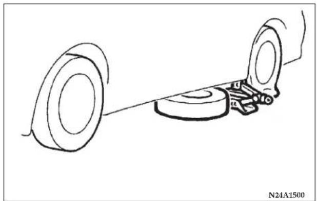
natural_image
Technical line drawing of a mechanical assembly with two rollers and a base plate (no text or symbols)NOTE: Place the spare wheel under the vehicle body near the jack; this helps to minimize danger should the jack slip out of position.
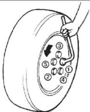
- Remove the wheel nuts with the wheel nut wrench, then take the wheel off.
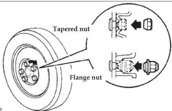
CAUTION!
Handle the wheel cover carefully when replacing the flat tire, to avoid the wheel surface becoming scratched and causing premature corrosion.
NOTE: Clear out any mud, etc. on the hub surface, hub bolts or in the installation holes in the wheel.
- Install the spare wheel with the nut's tapered end facing inward, then tighten by hand until the wheel is no longer loose.
272 EMERGENCIES
CAUTION!
Never apply oil to either wheel bolts or nuts as it can cause them to overtighten.
NOTE: Flange nuts can be temporarily used on the steel wheel, but return to the original wheel and tire as soon as possible.
If all four wheels are changed to steel wheels, use tapered nuts.
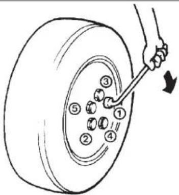
N24A0220
- Lower the vehicle slowly and then tighten the nuts in the sequence shown in the illustration until each nut has been tightened to the specified torque.
88 to 108 N·m (65 to 80 ft lb)
CAUTION!
Never use extra force with your foot on the wheel nut wrench or a pipe extension as you can over-tighten the nut.
- Lower and remove the jack, and store the jack, flat tire and chock. Have the damaged tire repaired as soon as possible.
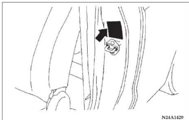
- Check tire inflation pressure. Tire inflation pressure specifications are shown on a placard located on the driver's side "B"-Pillar.
CAUTION!
- The emergency tire is to be used only temporarily when the standard tire is damaged. Repair the damaged tire as soon as possible. Replace the emergency tire with the standard tire.
- After changing the tire and driving the vehicle approximately 621 miles (1000 km), retighten the wheel nuts to make sure that they are not loose.
- If the steering wheel vibrates after changing the tire, have the tire checked for balance at an authorized dealer.
- Avoid mixing one type of tire with another type or using tires of a size other than the specified size. Premature mechanical wear and reduced handling may result.
ENGINE OVERHEATING
If the engine coolant temperature gauge indicator enters the "H" (hot) position, the engine may be overheated.
In any of the following situations, you can reduce the potential for overheating by taking the appropriate action.
- On the highways — Slow down.
- In city traffic — While stopped, put transaxle in neutral, but do not increase engine idle speed.
NOTE: There are steps that you can take to slow down an impending overheat condition. If your air conditioner is on, turn it off. The air conditioning system adds heat to the engine cooling system and turning off the A/C removes this heat. You can also turn the Temperature control to maximum heat, the Mode control to floor, and the fan control to High. This allows the heater core to act as a supplement to the radiator and aids in removing heat from the engine cooling system.
CAUTION!
Driving with a hot cooling system could damage your vehicle. If temperature gauge reads "H", pull over and stop the vehicle. Idle the vehicle with the air conditioner turned off until the pointer drops back into the normal range. If the pointer remains on the "H", turn the engine off immediately, and call for service.
WARNING!
A hot engine cooling system is dangerous. You or others could be badly burned by steam or boiling coolant. You may want to call a service center if your vehicle overheats. If you decide to look under the hood yourself, see Maintenance Section of this manual. Follow the warnings under the Cooling System Pressure Cap paragraph.
WARNING!
- When working near the radiator cooling fan, disconnect the fan motor lead or turn the ignition key to the OFF position. The fan is temperature controlled and can start at any time the ignition key is in the ON position.
- You or others can be badly burned by hot coolant or steam from your radiator. If you see or hear steam coming from under the hood, don't open the hood until the radiator has had time to cool. Never try to open a cooling system pressure cap when the radiator is hot.
JUMP-STARTING THE ENGINE
If the engine cannot be started because the battery is weak or dead, the battery from another vehicle can be used with booster cables to start the engine.
276 EMERGENCIES
WARNING!
When using jumper cables to start a vehicle, follow procedures exactly and exercise extreme caution.
CAUTION!
Do not try to start your vehicle by pushing or towing. Vehicles equipped with an automatic transaxle cannot be started this way. Pushing or towing a vehicle equipped with a manual transaxle may overheat and damage the catalytic converter. Also, there is a greater risk of an accident when a vehicle is being pushed or towed.
- Remove any metal jewelry such as watch bands or bracelets that might make an inadvertent electrical contact.
- Position the vehicles close enough together so the booster cables can reach, but be sure the vehicles aren't touching each other. If they are, it could cause a ground
connection. You wouldn't be able to start your vehicle, and the bad ground could damage the electrical systems.
CAUTION!
Check the other vehicle. It must have a 12-volt battery. If the other system isn't 12-volts, both systems can be damaged.
- You could be injured if the vehicles move. Set the parking brake firmly on each vehicle. Put an automatic transaxle in "P" (PARK) or a manual transaxle in "N" (Neutral). Turn the ignition key to the "LOCK" position.
WARNING!
Turn the ignition key to the "LOCK" position on both vehicles. Use care to make sure that the cables or your clothes are never caught by the fan or drive belt. Personal injury could result.
NOTE: Turn off all lights, heater and other electrical loads. This will avoid sparks and help save both batteries.
- Make sure battery electrolyte is at the proper level. (See "Battery" on page 317.)
WARNING!
If electrolyte fluid is not visible, or appears to be frozen, do not attempt jump starting. The battery might rupture or explode if the temperature is below the freezing point or if it is not filled to the proper level.
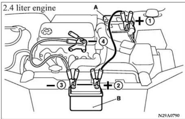
278 EMERGENCIES
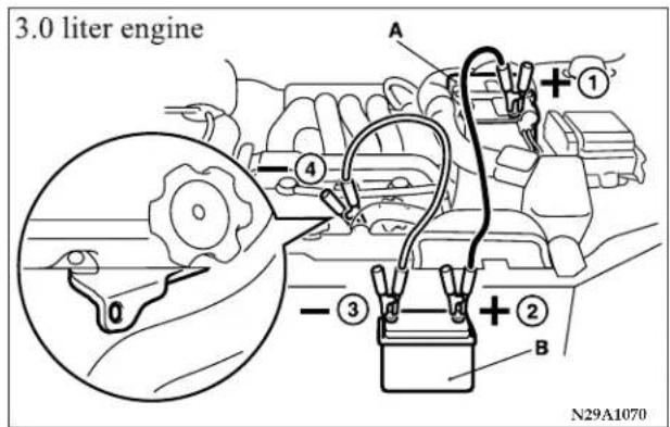
- Connect one end of one booster cable to the positive (+) terminal of the discharged battery (A), and the other end to the positive (+) terminal of the booster battery (B).
NOTE: Remove the terminal cover before connecting the booster cable to the positive terminal of the battery.
Use the proper cables suitable for the battery size. Otherwise heat damage to the cables could result. Check the booster cables for damage and corrosion before use.
- Connect one end of the other jumper cable to the negative (-) terminal of the booster battery (B), and the other end to the engine block of the vehicle with the discharged battery (A) at the point farthest from the battery.
WARNING!
- Be sure to observe the connecting sequence of ① → ② → ③ → ④.
- Make sure that the connection ④ is made to the engine properly. If the connection is directly made to the negative side of the battery, the flammable gases generated from the battery might catch fire and explode.
- When connecting the booster cable, do not connect the positive (+) cable to the negative (-) terminal. Otherwise sparks might cause explosion of the battery.
- Use care not to have the booster cable caught in the cooling fan or other rotating parts in the engine compartment.
WARNING!
- Charging the battery installed in the vehicle might cause the battery to catch fire and explode. Or, damage to the vehicle could result. If it has to be charged in that condition for unavoidable reasons, disconnect the vehicle side negative lead.
- Keep sparks, cigarettes and flames away from the battery because the battery may produce an explosion.
- Use adequate ventilation when charging or using the battery in an enclosed space.
- Remove all the caps before charging the battery.
- Electrolyte (battery acid) is corrosive diluted sulfuric acid. If electrolyte comes in contact with your hands, eyes, clothes, or the painted surface of your vehicle, thoroughly flush with water. If electrolyte gets in your eyes, flush them thoroughly with water immediately, and get prompt medical attention.
WARNING!
- Always wear protective clothing and goggles when working near the battery.
- Keep the battery out of the reach of children.
If your vehicle has anti-lock brakes
If the vehicle is driven without sufficient battery charge, after the engine has been started by using booster cables, the engine may misfire. This can cause the anti-lock braking system warning light to blink on and off. This is a result of insufficient battery voltage; it is not a malfunction of the brake system. If this happens, fully charge the battery before driving.
TOWING
When towing your vehicle, all state and local regulations for towing must be followed. Incorrect towing equipment could damage your vehicle. When towing is required, contact a professional towing service and make sure that flat bed type, dolly type or wheel lift type towing equipment is used. Do not attempt to be towed by another vehicle with a rope using the tie-down hooks.
CAUTION!
- Tie-down hooks should never be used for towing purposes.
- This vehicle can NOT be towed by a tow truck using sling lift type equipment. This is to prevent the bumper from deformation. If this vehicle is towed, use wheel lift, dolly type or flat bed equipment.
- Use the flat bed type, dolly type or dolly type equipment if a vehicle has the following conditions:
- Any of the transaxle, axles, steering system or power train is damaged.
• Automatic transaxle fluid level is low.
Sling lift type
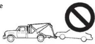
Flat bed type
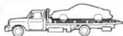
Dolly type
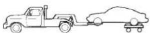
Wheel lift type
Front wheel lift
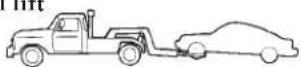
Rear wheel lift
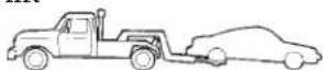
N25A0202
CAUTION!
- Towing should only be done by a professional tow service particularly if it will involve towing on winding roads, hills or heavy traffic. If you have any doubts, use a professional tow service.
Towing—front wheel lift
Place the gearshift lever (manual transaxle) to Neutral or the selector lever (automatic transaxle) in the "N" (NEUTRAL) position. Release the parking brake.
Towing—rear wheel lift
Turn the ignition key to the "ACC" position and secure the steering wheel in a straight-ahead position with a rope or similar device. Never place the ignition key in the "LOCK" position. This will result in damage to the steering lock mechanism.
If you have to tow an automatic transaxle model with the rear wheels raised (with the front wheels on the ground):
Observe the following restricted towing speeds and distances.
• Speed: 30 mph (50 km/h)
• Distance: 18 miles (30 km)
282 EMERGENCIES
CAUTION!
Never tow an automatic transaxle model with the rear wheels raised (with the front wheels on the ground) when the automatic transaxle fluid level is low. This may cause serious and expensive damage to the transaxle.
FUSES
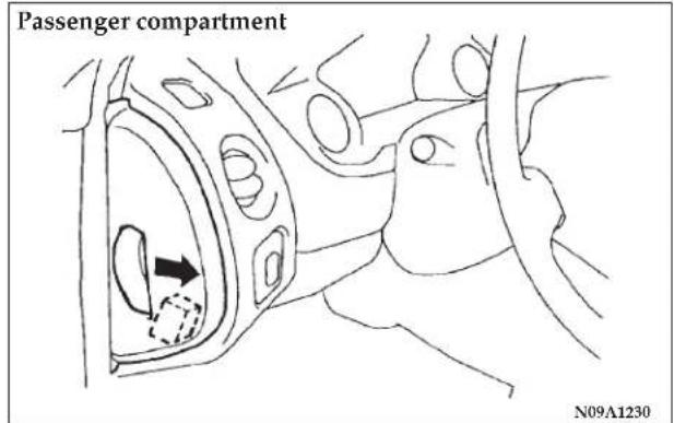
Fuse block
To prevent damage to the electrical system due to short-circuiting or overloading, each individual circuit is provided with a fuse. There are fuse blocks in the passenger compartment and in the engine compartment.
The fuse block in the passenger compartment is located on the driver's side at the position shown in the illustration.
Engine compartment
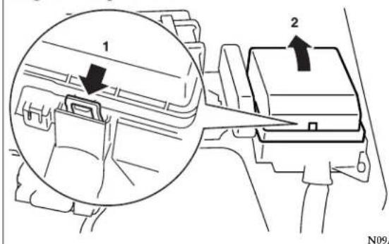
In the engine compartment, the fuse block is located as shown in the illustration.
FUSIBLE LINKS
Fusible links will melt to prevent a fire in the event that a large current flows through a system protected by a fusible link. In case of a melted fusible link, see your authorized dealer for inspection and replacement.
Fuse load capacities
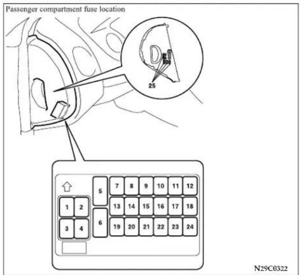
The fuse cover lists the names of the electrical systems and the fuse capacities. Spare fuses are contained in the
cover of the instrument panel (driver's side). Always use a fuse of the same capacity for replacement.
Passenger compartment fuse location
Fuse location table
| No. | Symbol E | Electrical system Capacity | |
| 1 | Audio 20A | ||
| 2 | — | — | — |
| 3 | Sunroof 20A | ||
| 4 | SOCKET | Accessory socket 15A | |
| 5 | Rear window defogger 30A | ||
| 6 | Heater 30A | ||
| 7 | — | — | — |
| 8 | — | — | — |
| 9 | SOCKET | Accessory socket 15A | |
| 10 | Door lock 15A | ||
| 11 | Rear window wiper 15A | ||
| 12 | — | — 15A | |
| 13 | Relay | 7.5A | |
| 14 | Electric remote-controlled outside mirror | 7.5A | |
| 15 | — | — | — |
| 16 | Cigarette lighter | 15A |
| No. | Symbol E | Electrical system | Capacity |
| 17 | Engine Control | 7.5A | |
| 18 | Windshield wiper | 20A | |
| 19 | Door mirror heater | 7.5A | |
| 20 | Relay | 7.5A | |
| 21 | CRUISE | Cruise control | 7.5A |
| 22 | Back up light | 7.5A | |
| 23 | Gauge 7.5A | ||
| 24 | Engine control | 10A | |
| 25 | — | Spare fuse | 30A |
| 20A | |||
| 15A | |||
| 10A |
- Some fuses may not be installed on your vehicles, depending on the vehicle model or specifications.
- The table above shows the main equipment corresponding to each fuse.
Spare fuse location
Spare fuses are contained in the cover of the instrument panel (driver's side). Always use a fuse of the same capacity for replacement.
Engine compartment Fuse location table
Engine compartment fuse location
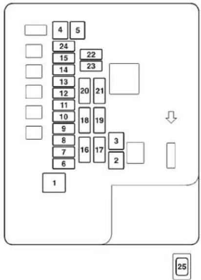
N29B2642
| No. | Symbol Electrical system Capacity | ||
| 1 | Fuse (+B) 60A | ||
| 2 | Radiator fan motor 50A | ||
| 3 | Anti-lock braking system 60A | ||
| 4 | Ignition switch 40A | ||
| 5 | Electric window controls 30A | ||
| 6 | Fog lights 15A | ||
| 7 | — | — — | |
| 8 | Horn 15A | ||
| 9 | Engine control 20A | ||
| 10 | Air conditioning 10A | ||
| 11 | STOP | Stop lights 15A | |
| 12 | — | — | |
| 13 | Alternator 7.5A | ||
| 14 | Hazard warning flasher | 10A | |
| 15 | A/T | Automatic transaxle | 20A |
| 16 | Headlights high beam (right) 10A | ||
| 17 | Headlights high beam (left) | 10A | |
| 18 | Headlights low beam (right) | 10A | |
| 19 | Headlights low beam (left) | 10A | |
| 20 | Position lights (right) | 7.5A | |
| 21 | Position lights (left) | 7.5A | |
| No. | Symbol Electrical system Capacity | ||
| 22 | Dome lights | 10A | |
| 23 | Audio | 10A | |
| 24 | Fuel pump | 15A | |
| 25 | DEF | Defroster | 40A |
- Some fuses may not be installed on your vehicle. Fuse application depends on the vehicle model, specifications, or options.
- Before replacing a fuse, always turn off the electrical item concerned and turn the ignition key to the "LOCK" position.
- Remove the fuse cover.
- Referring to the fuse location diagrams and corresponding tables, check the fuse that relates to the problem.
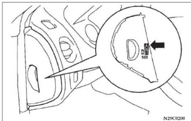
- There is a fuse puller in the cover of the instrument panel (driver's side). Remove the fuse puller, clamp it on the fuse you wish to remove, and pull the fuse straight out from the fuse block. If the fuse is not blown, something else must be causing the problem; contact an authorized dealer to have the problem checked.
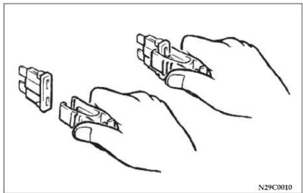
natural_image
Line drawing of hands holding two electronic connectors (no text or symbols)- Insert a new fuse of the same capacity securely into the fuse block location.
CAUTION!
- Never use a fuse with a capacity larger than that specified or any substitute, such as wire, foil, etc. Doing so will cause the circuit wiring to heat up and could cause a fire.
- If the newly inserted fuse blows again after a short time, have the electrical system checked by an authorized dealer to find and correct the cause.
REPLACEMENT OF LIGHT BULBS
Before replacing a bulb, be sure the light is off. Do not touch the glass part of the new bulb with your bare fingers; the skin oil left on the glass will evaporate when the bulb gets hot and the vapor will condense on the reflector and dim the surface.
Bulb capacity
A bulb should only be replaced with a new bulb of the same rating and type. The designation can be found on the base of the bulb.
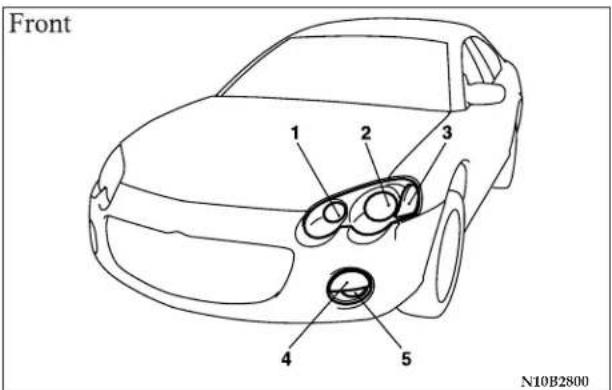
Outside
| Description | Wattage or Candela Power | ANSI Trade No. or Bulb type |
| 1 - Headlight (Type 1) 60W 9005 X/S | (HB3A) | |
| 2 - Headlight (Type 2) 51W 9006 X/S | (HB4A) | |
| 3 - Front side marker light | 1.5cp 194NA | |
| 4 - Front turn signal and parking light | 2.2cp NAk | |
| 5 - Front fog light 37.5W 896 |
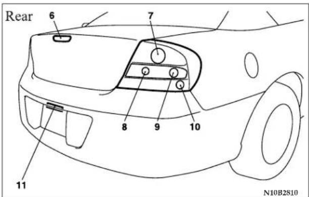
| Description | Wattage or Candela Power | ANSI Trade No. or Bulb type |
| 6 - High-mounted stop light | 18W (W16W) — | |
| 7 - Stop and tail light 32/3cp | 1157 | |
| 8 - Back up light 18W 921 | ||
| 9 - Rear turn signal light 32cp | 1156NA | |
| 10 - Rear side marker light | 3cp | 168 |
| 11 - License plate light 3cp | 168 | |
290 EMERGENCIES
Inside
| Description | Wattage or Candela Power |
| Dome Light 10W | |
| Rear personal light 8W | |
| Trunk light 5W | |
| Reading light 4W |
Headlights (Type 1)
- Turn the light socket counterclockwise and pull it out and remove the light bulb.
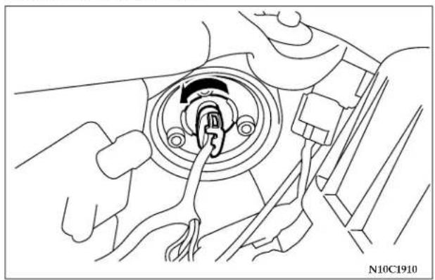
natural_image
Line drawing of a car interior showing hands adjusting a circular component with a finger inserted (no text or symbols)- Pull the clip (A) and remove the light bulb from the socket.
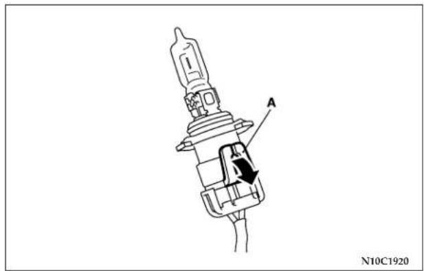
Headlights (Type 2)
- Loosen the bolt (A), move the horn (B) (left side only).
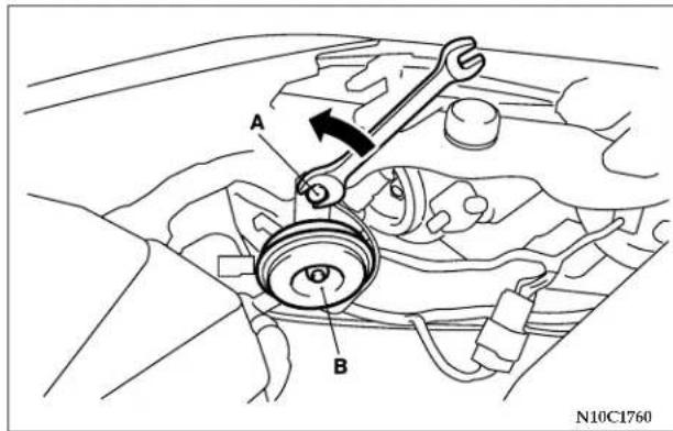
292 EMERGENCIES
- Turn the light socket counterclockwise and pull it out and remove the light bulb.
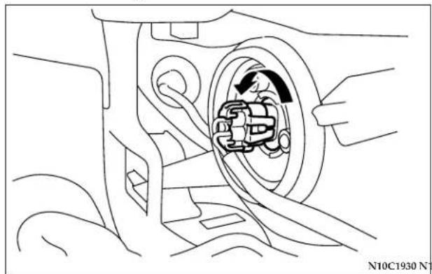
natural_image
Line drawing of a car interior showing a person inside a vehicle wheel (no text or symbols)- Pull the clip (A) and remove the light bulb from the socket.
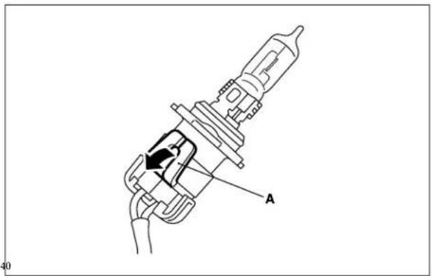
CAUTION!
- Never hold the halogen light bulb with a bare hand, dirty glove, etc. The oil from your hand could cause the bulb to break the next time the headlights are operated.
If the glass surface is dirty, it should be cleaned with alcohol and installed after drying thoroughly.
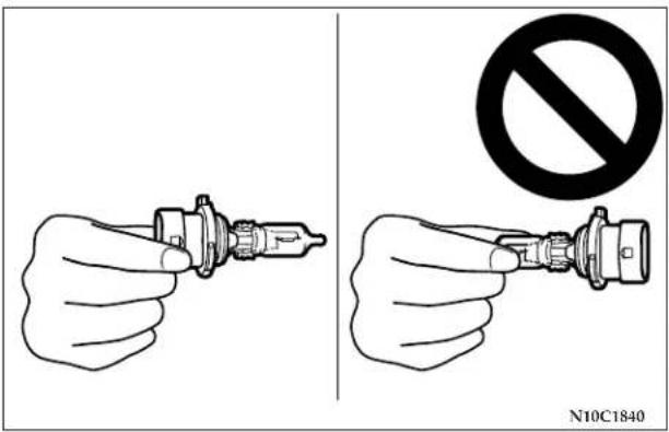
Adjustment of headlight aim
The alignment of the headlights should be checked by an authorized dealer.
Front turn signal and parking lights
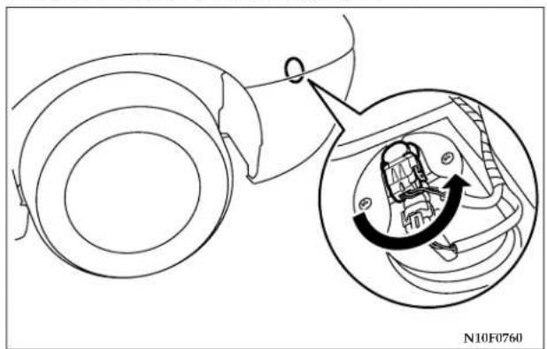
natural_image
Technical diagram showing a mechanical assembly with an inset close-up of a component (no text or symbols)Turn the light socket counterclockwise and pull it out and remove the light bulb.
294 EMERGENCIES
Front side marker lights
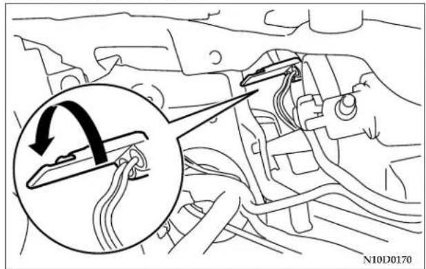
Turn the light socket counterclockwise and pull it out and remove the light bulb.
Front fog lights
- Turn the front turn signal light socket counterclockwise.
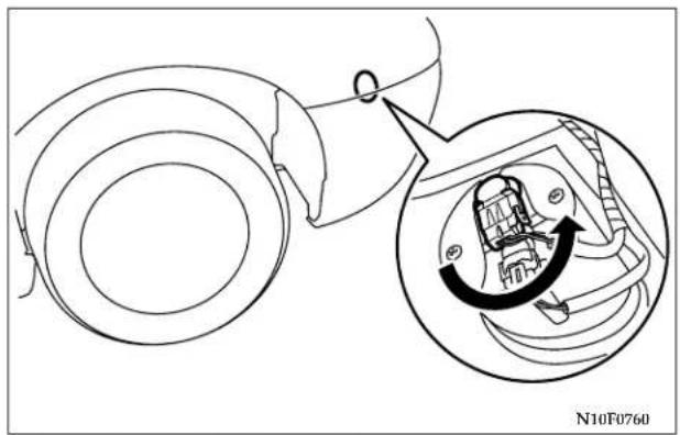
natural_image
Mechanical assembly diagram showing a rotating component with a circular inset view (no text or symbols)- Turn the light socket counterclockwise and pull it out.
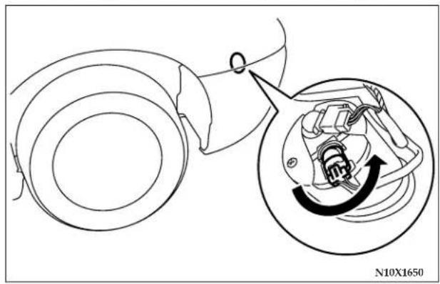
natural_image
Diagram showing a car wheel assembly with a magnified inset illustrating the internal components (no text or symbols)- Pull both clips away from the center as shown and remove the bulb from the socket by pulling out.
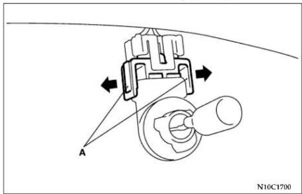
296 EMERGENCIES
CAUTION!
- Never hold the halogen light bulb with a bare hand, dirty glove, etc. The oil from your hand could cause the bulb to break the next time the fog lights are operated. If the glass surface is dirty, it should be cleaned with alcohol and installed after drying thoroughly.
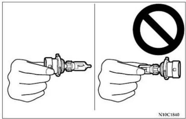
Rear combination lights
- Turn the trim cover clip (A) counterclockwise and remove the trim cover clip. Partially remove the trim cover in the trunk.
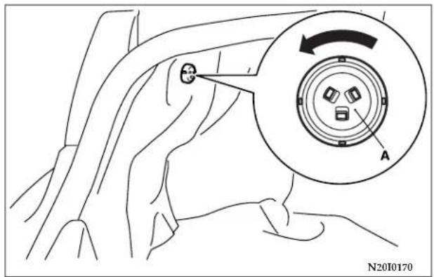
- Remove the light case mounting nuts. Disconnect the connector.
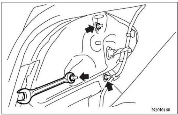
natural_image
Technical diagram of a mechanical assembly with wrench and valve components (no text or labels)- Slide the light unit outward to remove it. Remove each bulb socket assembly by turning it counterclockwise.
Remove the bulb from the socket by turning it counterclockwise while pressing it inward.
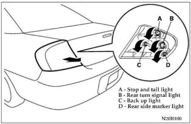
298 EMERGENCIES
High-mounted stop light
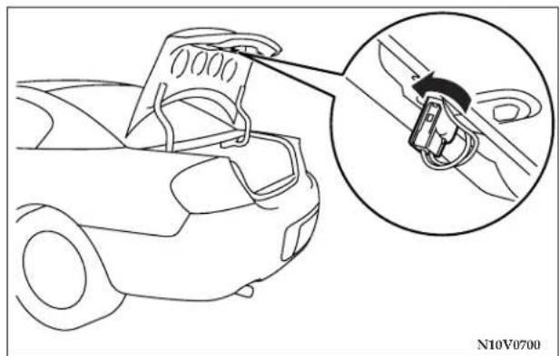
natural_image
Line drawing of a car interior showing a seatbelt buckle and a magnified inset view (no text or symbols)Remove the socket assembly and bulb together by turning it counterclockwise.
Remove the bulb from the socket by pulling out.
License plate light
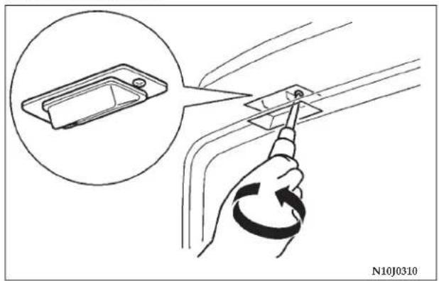
natural_image
Illustration of a hand holding a connector with a magnified inset showing a device component (no text or symbols)Remove the lens mounting screws, remove the socket assembly and the bulb together by turning it counterclockwise. And remove the bulb by pulling out.
Trunk light
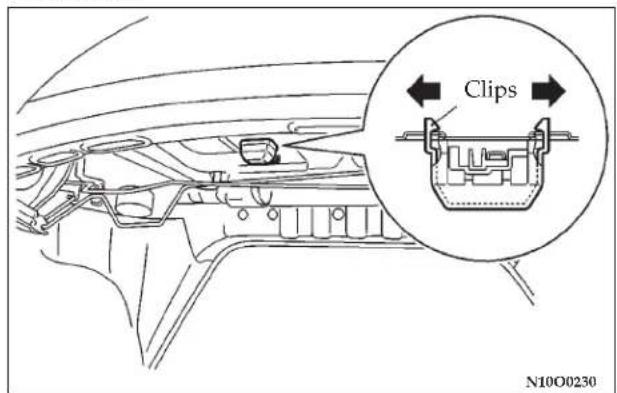
Pull both clips away from the center as shown and remove the light unit. Then remove the bulb by pulling out.
Dome light
- Insert a flat blade screwdriver into the notch of the light assembly and pry gently downward to remove it.
Type 1
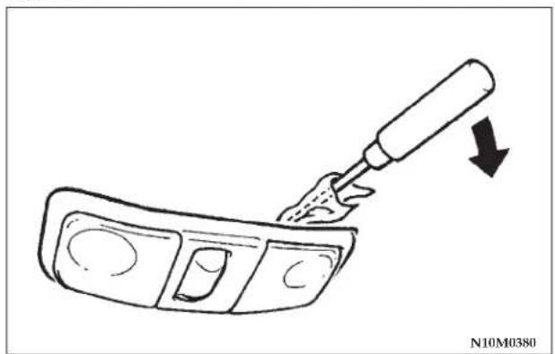
natural_image
Line drawing of a tool applying material to a curved component, with an arrow indicating direction (no text or symbols)NOTE: Wrap a cloth around the tip of the screwdriver to avoid scratching the light assembly.
300 EMERGENCIES
2. Remove the light bulb from the light holder. Reading lights
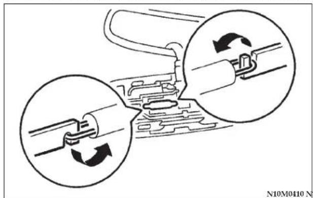
natural_image
Diagram showing two mechanical components with rotating arrows, no text or symbols present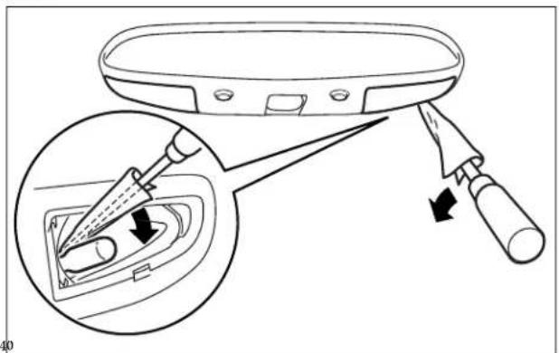
Insert a straight blade screwdriver into the notch of the light assembly and pry gently to remove the lens.
Remove the light bulb from the light holder.
NOTE: Wrap a cloth around the tip of the straight blade screwdriver in order to avoid scratching the lens.
Rear personal light
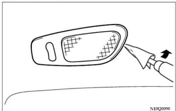
natural_image
Line drawing of a hand holding a tool interacting with a device (no text or symbols)Insert the tip of a flat blade screwdriver at the edge of the lens, pry gently to remove the lens, and then remove the bulb from the light holder.
NOTE: Wrap a cloth around the tip of the screwdriver in order to avoid scratching the lens.
MAINTENANCE
CONTENTS
■ View of engine compartment ..... 3 0 5
■ Service precautions .... 3 0 6
■ Emission-control system maintenance ..... 3 0 7
■ Emissions Testing 308
■ Onboard Diagnostic System (OBD II) ..... 3 0 8
■ Replacement Parts....309
□ Fuel system (tank, filler tube, connections, and fuel tank filler cap) 309
□ Fuel hoses....309
□ Air cleaner filter....3 1 0
□ Evaporative emission control system (except evaporative emission canister) . . . . . . 3 1 0
□ Spark plugs. 3 1 1
□ Ignition cables....3 1 1
□ Distributor cap and rotor .... 3 1 1
General maintenance 312
□ Engine oil and oil filter. 3 1 2
Engine coolant. 316
□ To check the coolant level....3 1 6
□ To add coolant. 316
Brake fluid 317
Clutch fluid (manual transaxle) 318
□ To check the clutch fluid. 3 1 8
□ To check the clutch fluid. 3 1 8
□ To check the clutch fluid. 3 1 8
□ To check the clutch fluid. 3 1 8
□ To check the clutch fluid. 3 1 8
□ To check the clutch fluid. 3 1 8
□ To check the clutch fluid. 3 1 8
□ To check the clutch fluid. 3 1 8
□ To check the clutch fluid. 318
□ To check the clutch fluid. 3 1 8
□ To check the clutch fluid. 3 1 8
□ To check the clutch fluid. 3 1 8
□ To check the clutch fluid. 3 1 8
□ To check the clutch fluid. 3 1 8
□ To check the clutch fluid. 3 1 8
□ To check the clutch fluid. 3 1 8
□ To check the clutch fluid. 3 1 8
□ To check the clutch fluid. 3 1 8
□ To replace the fluid ..... 3 1 8
□ To replace the fluid ..... 3 1 8
□ To replace the fluid ..... 3 1 8
□ To replace the fluid ..... 3 1 8
□ To replace the fluid ..... 3 1 8
□ To replace the fluid ..... 3 1 8
□ To replace the fluid . . . . . . . . . . . . . . . . . . . . . . . . . . . 3 1 8
□ To replace the fluid ..... 3 1 8
□ To replace the fluid ..... 3 1 8
□ To replace the fluid....318
□ To replace the fluid ..... 3 1 8
□ To replace the fluid ..... 3 1 8
□ To replace the fluid ..... 3 1 8
□ To replace the fluid ..... 3 1 8
□ To replace the fluid ..... 3 1 8
□ To replace the fluid ..... 3 1 8
□ To replace the fluid ..... 3 1 8
□ To replace the fluid ..... 3 1 8
Battery 319
□ During cold weather .....319
304 MAINTENANCE
□ Disconnection and connection ..... 3 1 9
■ Automatic transaxle....3 2 1
□ To check the fluid level. 322
□ Procedure for checking the fluid level . . . . . . 3 2 2
■ Manual transaxle....3 2 3
■ Disc brake pads, rear drum brake linings and rear wheel cylinders ..... 3 2 3
■ Brake hoses....3 2 3
■ Ball joint, steering linkage seal and drive shaft boots 323
■ Supplemental Restraint System (SRS) ..... 3 2 3
■ Door hinges, rear hatch hinges, hood lock release mechanism and safety catch ..... 3 2 4
■ Exhaust system .... 3 2 4
■ Windshield wiper blades ..... 3 2 5
□Windshield washers....325
■ Parking brake .... 3 2 6
■ Drive belt (for generator, water pump, power steering pump) 3 2 7
■ Timing belt .... 3 2 8
■ Tires 328
□Tire inflation pressures....328
□ Radial ply tires....3 3 0
☐ Tire pressure for sustained high-speed driving . . . 3 3 0
□ Oversize tires....3 3 0
□ Tire maintenance....3 3 1
□ Cargo loads. 3 3 1
□ Tread wear indicators....3 3 1
□ Tire rotation....3 3 2
□Tire chains. 3 3 3
□ Snow tires. 3 3 3
■ Regular Maintenance Schedule....3 3 4
■ Severe Maintenance Schedule....3 4 3
VIEW OF ENGINE COMPARTMENT
2.4 liter engine
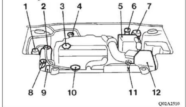
- Power steering fluid reservoir
- Engine coolant reservoir
- Engine oil filler cap
- Engine oil level dipstick
- Battery
-
Clutch fluid reservoir (manual transaxle only)
-
Brake fluid reservoir
- Windshield washer reservoir
- Drive belt
- Radiator cap
- Automatic transaxle fluid level dipstick
- Air cleaner filter
3.0 liter engine
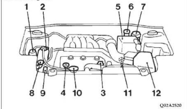
306 MAINTENANCE
NOTE: The Scheduled Maintenance Charts are located in the rear of this maintenance section. Always refer to the schedules for proper service intervals.
SERVICE PRECAUTIONS
Adequate care of your vehicle at regular intervals serves to preserve the value and appearance as long as possible. Some maintenance items can be performed by the owner, while others should be done only by an authorized dealer.
This section describes only those items which can be performed by the owner. In the event a malfunction or other problem is discovered, have it corrected by an authorized dealer.
This section contains information on inspection maintenance procedures that you can do yourself, if you so desire. Follow the instructions and precautions for each of the various procedures.
WARNING!
- When checking or servicing the inside of the engine compartment, be sure the engine is stopped and has had a chance to cool down.
- If it is necessary to do work in the engine compartment with the engine running, be especially careful that your clothing, hair, etc. does not become caught by the fan, drive belts, or other moving parts.
WARNING!
- The fan may turn on automatically even if the engine is not running; turn the ignition key to the "LOCK" position and remove the key to ensure safety while you work in the engine compartment.
- Do not smoke, or allow open flames around fuel or the battery. The fumes are flammable.
- Be extremely cautious when working around the battery. It contains poisonous and corrosive sulfuric acid.
- Do not get under your vehicle with just the car's jack supporting it. Always use properly rated automotive jack stands.
- Improper handling of components and materials used in the vehicle can endanger your personal safety. Consult an authorized dealer if you have questions.
Your vehicle is equipped with an emission-control system which satisfies all requirements of the U.S. Environmental Protection Agency. The emission-control system consists of:
(1) a positive crankcase ventilation system
(2) an evaporative emission-control system
(3) an exhaust emission-control system.
The "Scheduled" maintenance services listed must be performed at the times or mileages specified to assure the continued proper functioning of the emission-control system. These, and all other "General" maintenance services included in this manual, should be performed to provide the best vehicle performance and reliability.
More frequent maintenance may be needed for vehicles driven under severe operating conditions such as dusty areas and frequent start and stop driving.
In order to assure the proper function of the emission-control system, it is recommended that you have your vehicle inspected and maintained by an authorized dealer in accordance with the schedule in this manual.
Inspection and service should also be performed any time a malfunction is suspected.
308 MAINTENANCE
EMISSIONS TESTING
In some localities, it may be or will become a legal requirement to ensure that all emissions components and systems are functioning properly as a part of the test procedure. The test center accomplishes this by checking the On Board Diagnostic System system (OBD) with an electronic scan tool. If your vehicle has recently been serviced, the OBD system may have been reset to a "not ready" condition because the OBD system has not had sufficient time since the servicing to reconfirm that emissions components are operating properly. In most cases, a reasonable mix and amount of normal city and highway driving and at least one overnight-off period will be required to prepare your vehicle for this check; however your DaimlerChrysler Motors Corporation dealer has the equipment and procedures required to make certain that the OBD system of your vehicle is ready for the required testing.
ONBOARD DIAGNOSTIC SYSTEM (OBD II)
To meet new government regulations and promote cleaner air, your vehicle is equipped with a sophisticated onboard diagnostic system called OBD II. This system monitors the performance of the emissions, engine, and automatic transaxle control systems. When these systems are operating properly, your vehicle will provide excellent performance and fuel economy, as well as engine emissions well within current government regulations.

If any of these systems require service, the OBD II system will turn on the Malfunction Indicator Light. It will also store diagnostic codes and other information to assist your service technician in making repairs. Al-
though your vehicle will usually be driveable and not need towing, see your dealer for service as soon as possible.
CAUTION!
Prolonged driving with the light on could cause further damage to the emission control system. It could also affect fuel economy and driveability. The vehicle must be serviced before any state emissions tests can be performed.
If the light is flashing, severe catalytic converter damage and power loss will soon occur. Immediate service is required.
If the gas cap is not tightened properly, the light may come on. Be sure the gas cap is tightened every time you add fuel. Tighten the cap until you hear it "click."
REPLACEMENT PARTS
Use of genuine Mopar parts for normal/scheduled maintenance and repairs is highly recommended to insure the designed performance. Damage or failures caused by the use of non-Mopar parts for maintenance and repairs will not be covered by the DaimlerChrysler Motors Corporation warranty.
Fuel system (tank, filler tube, connections, and fuel tank filler cap)
Check periodically for damage or leakage in the fuel lines and connections, and check for damage and looseness of the fuel tank filler tube cap. Particular attention should be paid to examining those fuel lines nearest to high heat sources such as the exhaust manifold.
WARNING!
If you see a fuel leak or if you smell fuel, do not operate the vehicle. Any spark (including from the ignition), flame or smoking material could cause an explosion or fire. Call an authorized dealer for assistance.
Fuel hoses
Inspect the surfaces of hoses for evidence of heat and mechanical damage, hard and brittle rubber, cracking, tears, cuts and abrasions. Particular attention should be paid to examining those hose surfaces nearest to high heat sources such as the exhaust manifold. Inspect all hose connections, such as clamps and couplings, to make sure they are secure and that no leaks exist. If there is any evidence of deterioration or damage, hoses should be replaced immediately.
310 MAINTENANCE
Air cleaner filter
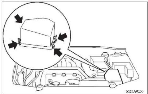
natural_image
Diagram of a vehicle engine bay with a magnified inset showing internal components (no text or symbols)The air cleaner filter will become dirty and loaded with dust during use, and the filtering effect will be substantially reduced. Replace it with a new filter in accordance with the schedule in this manual.
- Unclamp the air cleaner cover.
- Take out the air cleaner filter.
After replacing the air cleaner filter, reinstall the cover in its original position.
CAUTION!
Take care not to damage the engine air flow sensor when removing the air cleaner cover.
Evaporative emission control system (except evaporative emission canister)
If the fuel-vapor vent line is clogged or damaged, the fuel-vapor mixture will escape, polluting the atmosphere. Have the system checked at an authorized dealer at the mileage specified on the scheduled maintenance chart.
Spark plugs
Iridium tipped type
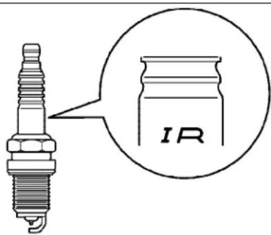
P15A0340
Spark plugs must fire properly to assure proper engine performance and emission-control.
Do not reuse spark plugs by cleaning or regapping. Spark plugs should be replaced at the mileage specified on the scheduled maintenance chart.
Your vehicle may be equipped with standard type spark plugs or iridium tipped ones. Iridium tipped spark plugs are identified by blue marks on the ceramic. They do not
require replacement as frequently as the conventional type spark plug and are designed to last much longer.
NOTE: Use the recommended or equivalent spark plugs listed under "Engine specifications" on page 361. Use of non-recommended plugs will cause engine damage, loss of performance or radio noise.
Ignition cables
The ignition cables should be kept clean, properly connected, and fully seated. Terminals should be fully seated and should not be removed from the distributor or coil towers unless they are damaged or cable testing indicates high resistance or broken insulation. Cracked, damaged, or faulty cables must be replaced.
Distributor cap and rotor
Check the distributor cap and rotor to maintain proper function and good emission control.
312 MAINTENANCE
GENERAL MAINTENANCE
The following pages contain the maintenance service recommended by DaimlerChrysler. In addition to the general maintenance items for which fixed maintenance intervals have been specified, there are other items which are expected to operate satisfactorily without periodic maintenance.
However, if a malfunction of these items does occur, it could adversely affect the engine or vehicle performance. These items should be inspected if a malfunction is observed or suspected.
See your authorized dealer for assistance, if you have any questions.
Engine oil and oil filter
2.4 liter engine
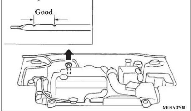
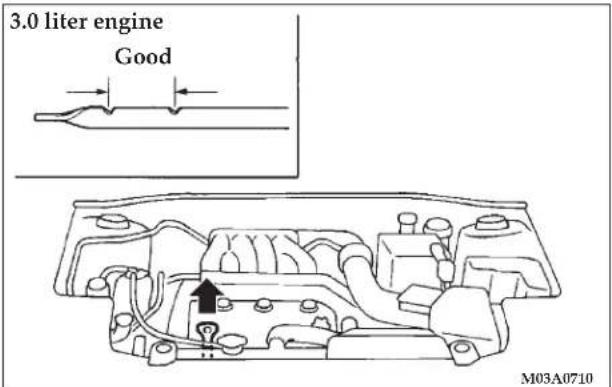
To check and refill engine oil
It is normal for an engine to consume some oil. You may find it necessary to add oil between the recommended oil change intervals. Before starting the engine, check the engine oil level. Replenish if necessary.
To check the oil level, remove the dipstick, wipe it off, and gently insert it fully into the crankcase. Slowly remove it again. The oil level must not exceed the range of "Good" on the dipstick.
NOTE: The engine must be "OFF" when performing oil level checks.
If the level does not reach the range of "Good", which indicates minimum necessary quantity of oil, remove the oil filler cap on the engine valve cover, and refill to within the "Good" range.
CAUTION!
Overfilling the crankcase will cause oil aeration and loss of oil pressure, which could damage the engine.
WARNING!
- Used engine oil is contaminated, and can cause skin problems: Avoid contact with the skin and wash thoroughly after working with used oil.
- Keep used oil out of reach of children.
314 MAINTENANCE
To replace the oil filter
The oil filter should be replaced at the time or mileage specified on the scheduled maintenance chart. You should be sure that any replacement filter used on this vehicle is a high quality filter. The manufacturer's specifications for Genuine DaimlerChrysler oil filters require that the filter be capable of withstanding a pressure of 256 psi (1.8MPa). A Genuine DaimlerChrysler oil filter is recommended as a replacement filter. Follow the installation instructions printed on the filter.
Engine oil identification mark
ILSAC certification mark ("Starburst" symbol)
M03A0150
Use only engine oils displaying the ILSAC certification symbol on the front of the container.
API service symbol
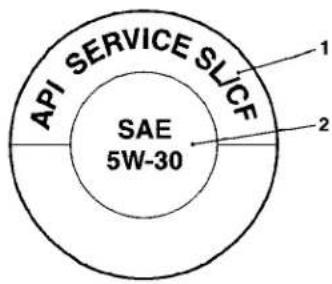
M03A1320
If you are unable to find oils with the ILSAC certification mark ("Starburst" symbol), an API classification SL, SL/CF oil with above label may be used.
This mark appears on the top of the oil containers and has three distinct areas for identifying various aspects of the oil.
- The top portion will indicate the quality of the oil.
- The center portion will show the SAE grade of the oil viscosity.
Recommended engine oil viscosity
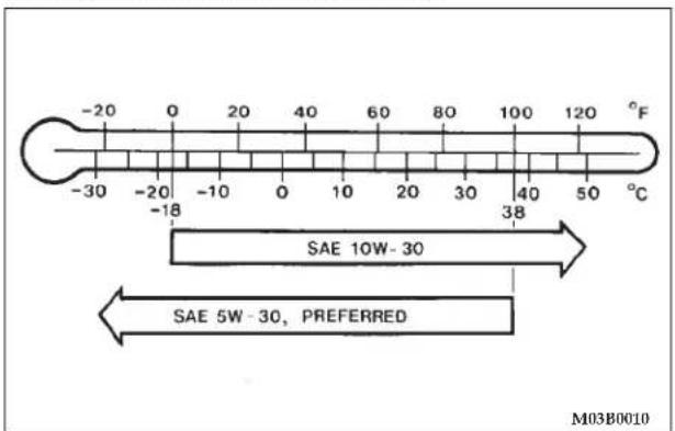
Use engine oil with proper thickness for the outdoor temperature where you will be driving.
SAE 5W-30 engine oil is best for the outdoor temperature range shown in the above chart.
You are strongly encouraged to use SAE 5W-30 engine oils to aid in low temperature starting and for improved fuel economy.
316 MAINTENANCE
ENGINE COOLANT
To check the coolant level
The coolant reserve system provides a quick visual method for determining the coolant level. When the engine is cold, the level of the coolant in the reserve tank should be between the FULL and LOW marks. The radiator normally remains completely full so there is no need to remove the radiator cap except for checking the coolant freeze point or replacing the antifreeze coolant.
To add coolant
Use DaimlerChrysler Genuine Coolant or an equivalent. Genuine Coolant provides excellent protection against corrosion and rust formation of all metals, including aluminum, and prevents clogs in the radiator, heater, cylinder head, engine block, etc. If frequent coolant additions are required, or if the level in the reserve tank does not drop when the engine cools, the system should be pressure-tested for leaks. Take your vehicle to an authorized dealer for inspection of the cooling system.
CAUTION!
- Do not use alcohol or methanol anti-freeze or any engine coolants mixed with alcohol or methanol anti-freeze. The use of an improper anti-freeze can cause corrosion of aluminum components.
- When additional coolant is needed to maintain the proper level, a minimum of 50% concentration of ethylene-glycol antifreeze in water should be added to the reserve tank. Do not overfill. A higher concentration (not to exceed 60%) should be used if a lower freezing point is required. The concentration level can be checked using instruments available at automotive supply stores, or can be done by your authorized dealer or service station. Use only high quality ethylene-glycol antifreeze coolant formulated to prevent corrosion of all cooling system metals.
- Do not top off with water only. Water by itself reduces the rust-protective and anti-freeze qualities of the coolant and has a lower boiling point. It can also cause damage to the cooling system if it should freeze. Do not use tap water, as it may cause corrosion and rust formation.
Radiator cap
The radiator cap must be fully tightened to prevent loss of coolant and engine damage.
WARNING!
Make sure that the engine is thoroughly cooled down before removing the radiator cap, otherwise hot steam or boiling coolant may gush from the filler port and scald you.
Points to remember
- Do not overfill the reserve tank.
- A special radiator cap is used to ensure sealing and to allow the coolant to return from the reserve tank to the radiator when the engine cools. If cap replacement is necessary, use the proper cap.
- Check the coolant freeze point in the radiator using proper instruments, when it is safe to do so. If antifreeze is added, the contents of the reserve tank must be protected against freezing.
-
Keep the front of the radiator clean. If your vehicle is equipped with air conditioning, keep the front of the condenser clean.
-
If the temperature of the engine coolant does not rise normally after engine warm-up, take the vehicle to an authorized dealer to have the thermostat checked, and replaced if necessary.
BRAKE FLUID
Recommended brake fluid conforming to DOT 3 or DOT 4 should be used. The reservoir cap must be fully tightened to avoid contamination from foreign matter or moisture.
CAUTION!
- Do not allow petroleum-based fluid to contact, mix with, or otherwise contaminate the brake fluid. Seal damage will result.
• Take care in handling brake fluid as it may cause damage to painted surfaces. - Use only the specified brake fluid. Also, the additives in different brands may result in a chemical reaction when mixed together, so avoid mixing different brands if possible.
- Keep the reservoir tank cap closed to prevent the brake fluid from evaporating or absorbing moisture.
CLUTCH FLUID (MANUAL TRANSAXLE)
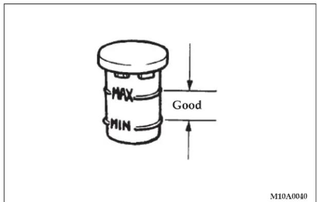
To check the clutch fluid
The clutch fluid in the clutch master cylinder should be checked when performing other underhood services. In addition, the system should be checked for leakage at the same time. Check to make certain that the clutch fluid level is always between the MAX and MIN level markings on the fluid reservoir and refill the fluid, if necessary. A rapid fluid loss indicates a leak in the clutch system which should be inspected by an authorized dealer and repaired immediately.
To replace the fluid
Recommended brake fluid conforming to DOT 3 or DOT 4 should be used.
The reservoir cap must be fully tightened to avoid contamination from foreign matter or moisture.
CAUTION!
- Do not allow petroleum-based fluid to contact, mix with, or otherwise contaminate the clutch fluid. Seal damage will result.
• Take care in handling clutch fluid as it may cause damage to painted surfaces. - Use only the specified clutch fluid. Also, the additives in different brands may result in a chemical reaction when mixed together, so avoid mixing different brands if possible.
- Keep the reservoir tank cap closed to prevent the clutch fluid from deteriorating due to moisture or air exposure.
BATTERY
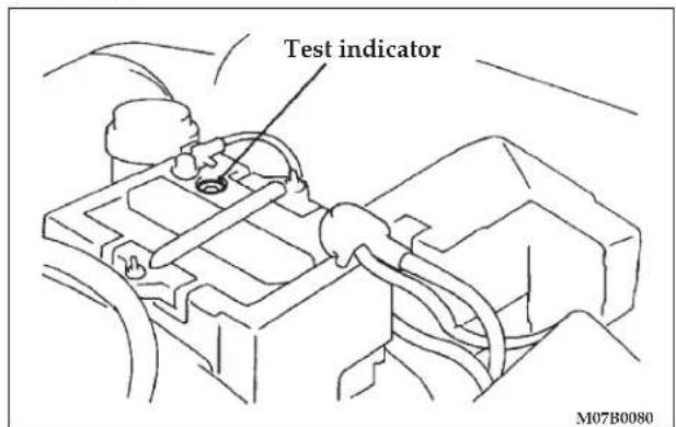
The condition of the battery is very important for quick starting and proper functioning of the vehicle's electrical system. Check the battery at regular intervals. To determine the battery charge, check the battery test indicator on top of the battery.
If the test indicator is a blue/green color when viewed from above, the battery is OK. A black colored indicator
means the battery is low on charge and may require charging. Have it checked at an authorized dealer.
During cold weather
The capacity of the battery is reduced at low temperatures. This is the result of its chemical and physical properties and this is why a very cold battery, particularly one that is not fully charged, will only deliver a fraction of the starter current that is normally available. It is recommended that you have the battery checked by an authorized dealer before the start of cold weather and, if necessary, have it charged or replaced. This not only ensures reliable starting, but prolongs battery life.
Disconnection and connection
To disconnect the battery cable, stop the engine, disconnect the negative terminal first, then the positive terminal. To reconnect the battery, first connect the positive terminal and then the negative terminal, before starting the vehicle.
WARNING!
- Never disconnect the battery while the engine is running; doing so could damage the vehicle's electrical components.
- Never short-circuit the battery; doing so could cause it to overheat and be damaged.
- Keep sparks, cigarettes and flames away from the battery because the battery may produce an explosion.
- Electrolyte (battery acid) is corrosive diluted sulfuric acid. If electrolyte comes in contact with, your hands, eyes, clothes, or the coated surface of your vehicle, thoroughly flush the area with water. If electrolyte gets in your eyes, flush them with water immediately and get prompt medical attention.
WARNING!
- Ventilate the area when charging or using the battery in an enclosed space.
- Always wear protective clothing and goggles when working with the battery, or have a skilled technician do it.
- If the battery is to be quick-charged, first disconnect the battery cables from the vehicle.
- In order to prevent a short circuit, be sure to disconnect the negative(-) terminal first, and reconnect it last.
- If the electrolyte level is very low, have the battery checked at an authorized dealer.
- Battery posts, terminals and related accessories contain lead and lead compounds. Wash hands after handling.
NOTE
- Check each battery terminal for corrosion. If necessary, neutralize corrosion by washing with a solution of baking soda and water. Apply grease to posts and clamps after cleaning or tightening.
- Before cleaning the battery, tighten all filler port caps to prevent foreign matter from entering the battery.
- Check to see if the battery is securely installed and cannot be moved. Also check each terminal for tightness.
- When the vehicle is to be left unused for a long period of time, remove the battery and store it in a place where the battery fluid will not freeze. The battery should be stored only in a fully charged condition.
AUTOMATIC TRANSAXLE
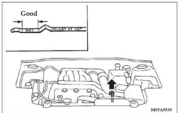
The automatic transaxle should be maintained and serviced by an authorized dealer to obtain the best performance and maximize life. It is important that the transaxle fluid be maintained at the level prescribed.
322 MAINTENANCE
To check the fluid level
The fluid level should be checked when the engine temperature gauge indicates a normal warmed up condition and the fluid in the transaxle is heated to its normal operating temperature. Operation with an improper fluid level will greatly reduce the life of the transaxle and the fluid.
Procedure for checking the fluid level
- With the parking brake engaged and the engine idling, select each gear momentarily, ending with the selector lever in the "N" (NEUTRAL) position.
- The fluid level should be at the HOT mark, but never above the HOT mark when the engine is at its normal warmed up condition. Add or drain as necessary to bring the fluid to this prescribed level.
- Make certain that the dipstick cap is reseated properly to prevent dirt and water from entering the transaxle.
WARNING!
Transaxle fluid is extremely flammable and poisonous. Do not spill fluid when adding or draining.
To add or change the fluid
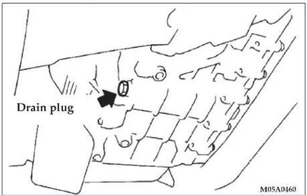
Use only recommended Mopar ATF+4 automatic transmission fluid to ensure optimum transaxle performance.
Special additives
DaimlerChrysler does not recommend the addition of any fluid additives to the transaxle.
MANUAL TRANSAXLE
Add oil to maintain the proper level. Refill or change oil according to the scheduled maintenance table.
Lubricant Gear Oil Classification GL-4
Viscosity range SAE75W-90 or 75W-85W
Proper brakes are essential to safe operation of your vehicle. Check brake pads and rear brake linings for wear, and check rear wheel cylinders for leakage. For proper braking performance, replace brake pads with original equipment type pads.
BRAKE HOSES
Brake hoses and tubing should be checked for:
- Severe surface cracking, scuffing or worn spots. If the casing of the hose is exposed by cracks or abrasions in the
rubber hose cover, the hose should be replaced. Deterioration of the hose could cause brake failure.
- Faulty installation may cause twisting, or wheel, tire or chassis interference.
BALL JOINT, STEERING LINKAGE SEAL AND DRIVE SHAFT BOOTS
Check the following parts for damage and grease leakage:
-
Ball joint boots of the front suspension and steering linkage
-
Bellows on both ends of the drive shaft
SUPPLEMENTAL RESTRAINT SYSTEM (SRS)
The entire SRS system must be inspected by an authorized dealer 10 years after the vehicle manufacture date shown on the certification label. [See "SRS servicing" on page 98.]
324 MAINTENANCE
DOOR HINGES, REAR HATCH HINGES, HOOD LOCK RELEASE MECHANISM AND SAFETY CATCH
The door hinges, trunk hinges, hood lock release mechanism and hood safety catch should be inspected, cleaned, and lubricated as required to maintain ease of operation and to provide protection against rust and wear. Apply engine oil to door hinges, hood hinges, and trunk hinges. Apply Multipurpose Grease NLGI Grade 2 sparingly to all sliding contact areas of the hood latch and release lever. Work lubricant into the hood lock mechanism until all frictional surfaces are covered.
Also, apply a film of the same lubricant to the pivot contact areas of the safety catch.
EXHAUST SYSTEM
WARNING!
Carbon monoxide gas found in the vehicle's exhaust is poisonous. Inhalation of exhaust fumes can cause unconsciousness or death.
The best protection against carbon monoxide entry into the vehicle interior is a properly maintained engine exhaust system.
Whenever a change is noticed in the sound of the exhaust system; when exhaust fumes can be detected inside the vehicle; or when the underside or rear of the vehicle is damaged, have a competent technician inspect the complete exhaust system and adjacent body areas for broken, damaged, deteriorated, or mispositioned parts. In addition inspect the exhaust system each time the vehicle is raised for lubrication or oil change. Replace as required.
Open seams or loose connections could permit dangerous exhaust fumes to seep into the trunk and passenger compartments.
Do this service when performing underbody service.
Check for any of the following conditions:
- Check for holes or exhaust gas leakage caused by corrosion or damage.
- Check the joints and connections for looseness or exhaust gas leakage.
- Check the rubber hangers and brackets for damage.
WINDSHIELD WIPER BLADES
Check the wiper blades occasionally. Periodic cleaning of the wiper blades is suggested to remove the accumulation of salt and road film. The wiper blade arms and glass areas should be cleaned with a sponge or cloth and a mild detergent or non-abrasive cleaner.
If the blades continue to streak or smear, they should be replaced.
NOTE: Do not operate wipers for long periods on dry glass; this accelerates deterioration of the rubber and could scratch the glass.
Windshield washers
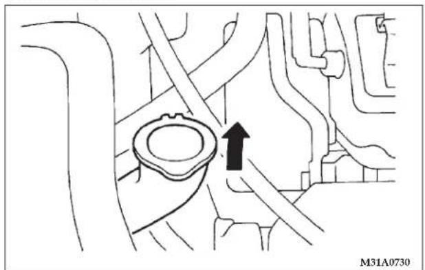
natural_image
Mechanical component diagram showing a valve or fitting with an arrow indicating direction (no text or symbols present)The windshield washer reservoir is in the engine compartment. Check the fluid level at regular intervals and replenish the fluid if necessary.
NOTE: When freezing weather is anticipated flush out the water in the reservoir by operating the pump. Fill the reservoir with windshield antifreeze (not radiator anti-freeze) and operate the system for a few seconds to flush out any residual water.
326 MAINTENANCE
PARKING BRAKE
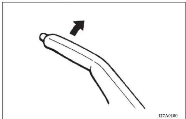
natural_image
Simple line drawing of a curved mechanical or tool-like component with an arrow indicating direction (no text or symbols)Check the parking brake lever travel occasionally. To check, pull the lever slowly and count the number of clicks of the ratchet.
For vehicles with rear drum brakes:
You should feel the parking brake take hold between 5 to 7 clicks.
For vehicles with rear disc brakes:
You should feel the parking brake take hold between 3 to 5 clicks. Also check to see if the lever is properly engaged with the ratchet, when pulled.
DRIVE BELT (FOR GENERATOR, WATER PUMP, POWER STEERING PUMP)
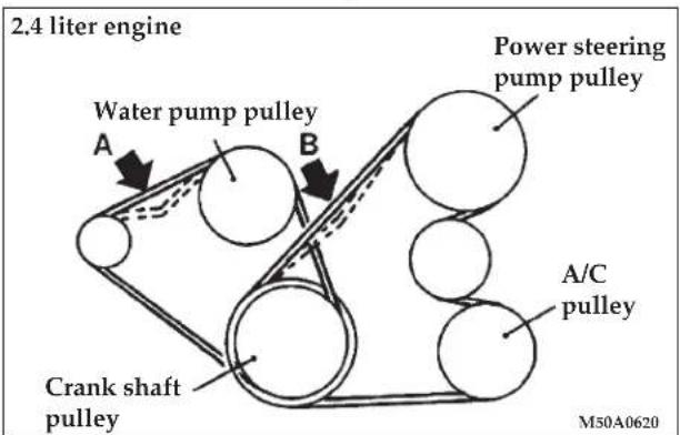
Check the tension of the drive belt. The deflection must be within specifications, when depressed at a point midway between the pulleys as shown in the illustrations with a force of about 100 N (22 lb.).
Inspect the drive belt for evidence of cuts and cracks, and replace it if damaged. When replacing the belt with a new belt, make sure that there is no interference between the belt and other engine components.
Then, check the tension of the belt at the designated point. The deflection must be within specification.
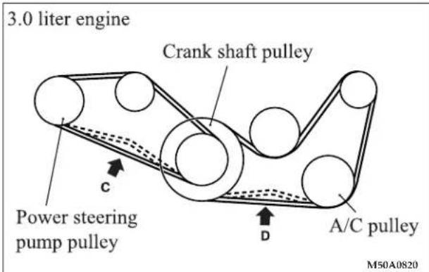
328 MAINTENANCE
Amount of belt deflection
in (mm)
| Standard value Used belt New belt | |||
| A .26 to .35(6.7 to 9.0) | .28 to .33(7.2 to 8.4) | .17 to .21(4.4 to 5.3) | |
| B .46 to .60(11.7 to 15.3) | .49 to .56(12.5 to 14.3) | .34 to .43(8.8 to 11.0) | |
| C .43 to .56(11.0 to 14.3) | .46 to .52(11.7 to 13.3) | .33 to .41(8.4 to 10.4) | |
| D .33 to .43(8.5 to 10.9) | .35 to .40(9.0 to 10.1) | .24 to .30(6.2 to 7.6) | |
WARNING!
Do not check or touch the drive belt with the engine running, or serious injury may result.
TIMING BELT
The timing belt should be replaced with a new one at the mileage specified on the scheduled maintenance chart.
TIRES
| WARNING! |
| Driving with tires that are worn or improperly inflated can result in a collision, and serious or fatal injury. |
Tire inflation pressures
Proper tire inflation pressure is essential to the safe and satisfactory operation of your vehicle. Three primary areas are affected by improper tire pressure:
1. Safety
Under-inflation increases tire flexing and can result in tire failure. Over-inflation results in a tire losing its ability to cushion shock. Objects on the road and potholes could cause tire damage that may result in tire failure.
2. Economy
Improper inflation pressures can cause uneven wear patterns to develop across the tire tread. These abnormal wear patterns will reduce tread life, resulting in a need for earlier tire replacement.
Under-inflation also increases tire rolling resistance and results in higher fuel consumption.
3. Ride comfort and vehicle stability
Proper tire inflation pressures contribute to the excellent ride quality built into your vehicle. Over-inflation produces an uncomfortable and jarring ride.
Under-inflation can produce a feeling of sluggish response.
Unequal inflation pressures can produce erratic and unpredictable vehicle response to steering maneuvers.
The proper tire pressure for your vehicle is listed on a placard attached near the door sill striker on the driver's door.
The recommended inflation pressures should be followed when the specified tires are installed.
| Item Tire size Front Rear | |||
| Normal tire P205/60 | R16 91H 32 psi (220 kpa) | ||
| P215/50R17 90H 32 psi (220 kpa) | |||
| Compact spare tire | T125/70D16 | 60 psi (420 kpa) | |
The pressures should be checked and adjusted, if necessary, at least once a month.
Tire pressures should be checked more often when weather temperatures vary widely, because tire pressures vary with
outdoor temperatures. Inflation pressures specified on the placard are always “cold inflation pressure”.
Cold inflation pressure can be measured after the vehicle has been stationary for at least three hours or driven less than one mile (1.6 km) after being stationary for three hours.
Cold inflation pressure must not exceed the maximum values molded into the tire sidewall. After driving several miles, tire inflation pressure may increase 2 to 6 psi (14 to 41 kPa) over the cold inflation pressure; do NOT let air out of the tires to match the specified cold pressure, or your tires will be underinflated.
Check your tires each time you refuel. If one tire looks lower than the others, check the tire inflation pressure for all of them. The following precautions also should be observed:
-
Keep your tires inflated to the pressures that are recommended. (See the tire and loading information placard attached on the latch on the driver's door.)
-
Stay within the load limits that are recommended.
330 MAINTENANCE
- Make sure that the weight of your vehicle load is evenly distributed.
- Drive at safe speeds.
- After the tire inflation pressure has been adjusted, check the tires for damage and air leaks. Be sure to replace the rubber caps on the valve stems.
Radial ply tires
Radial ply tires provide improved tread life, road hazard resistance and smoother high speed ride. The radial ply factory-installed tires on this vehicle are of belted construction and are selected to complement the ride and handling characteristics of your vehicle.
Radial ply tires have the same load carrying capacity as bias or bias-belted tires of the same letter size, and use the same recommended inflation pressures.
Mixing of radial ply tires with bias or bias-belted tires is not recommended. Combining radial ply and bias or bias-belted tires on one vehicle will negatively affect vehicle handling. It is recommended that radial ply tires should always be used as a set of four.
As longer wearing tires can be more susceptible to irregular tread wear, it is very important to follow the tire rotation interval shown in the section "Tire rotation" to achieve full tread life potential in these tires.
Cuts and punctures in radial ply tires are repairable only in the tread area, because of sidewall flexing. Consult your tire dealer for radial ply tire repairs.
Tire pressure for sustained high-speed driving
For sustained high-speed driving, increase inflation pressure 4 psi (28 kPa) above the recommended pressure but do not exceed the maximum cold inflation pressure molded into the tire sidewall.
Oversize tires
The use of tire sizes other than those listed may cause interference with vehicle components under extremes of suspension and steering travel, and may result in tire and vehicle damage.
Tire maintenance
The following maintenance steps are recommended:
- Check pressure regularly.
- Maintain wheel balance and front suspension alignment.
- Rotate tires regularly in accordance with the recommendation in the section "Tire rotation" on page 330.
Cargo loads
The load-carrying capacity of your vehicle is shown on the tire and loading information placard. DO NOT USE the weight rating data provided on the safety certification label for determining vehicle passenger and/or cargo load capacity.
For determining the combined weight of occupants and cargo, use the specifications provided on the tire and loading information placard.
Tread wear indicators
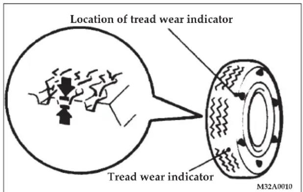
Tread wear indicators are built into the original equipment tires on your vehicle to assist you in determining when your tires have been worn to the point of needing replacement. Many states have laws making tire replacement mandatory at this point.
These indicators are molded into the bottom of the tread grooves and will appear as 1/2 in (13 mm) wide bands when tire tread depth becomes 1/16 in (1.6 mm).
332 MAINTENANCE
When the indicators appear in two or more adjacent grooves, tire replacement is recommended.
NOTE: The mark and the location of the tire wear indicator are different depending on tire manufacturers.
Tire rotation
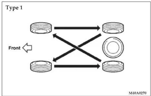
flowchart
graph TD
    A["Top Component"] --> B["Side Component"]
    C["Bottom Component"] --> D["Side Component"]
    E["Front"] <--> A
    E --> C
    style A fill:#f9f,stroke:#333
    style C fill:#f9f,stroke:#333
    style E fill:#f9f,stroke:#333
To equalize wear and help extend tire life, DaimlerChrysler recommends that you rotate your tires approximately every 7,500 miles (12,000 km) under normal driving conditions and every 6,000 miles (9,600 km) in severe driving conditions.
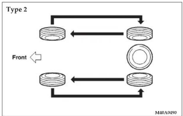
flowchart
graph TD
    A["Top Ring"] --> B["Bottom Ring"]
    B --> C["Left Side"]
    C --> D["Right Side"]
    D --> E["Bottom Ring"]
    E --> F["Left Side"]
    F --> G["Right Side"]
    G --> H["Bottom Ring"]
    H --> I["Left Side"]
    I --> J["Right Side"]
    J --> K["Bottom Ring"]
    K --> L["Left Side"]
    L --> M["Right Side"]
    M --> N["Bottom Ring"]
    N --> O["Left Side"]
    O --> P["Right Side"]
    P --> Q["Bottom Ring"]
    Q --> R["Left Side"]
    R --> S["Right Side"]
    S --> T["Bottom Ring"]
    T --> U["Left Side"]
    U --> V["Right Side"]
    V --> W["Bottom Ring"]
    W --> X["Left Side"]
    X --> Y["Right Side"]
    Y --> Z["Bottom Ring"]
However, the timing for tire rotation may vary according to your vehicle condition, road surface conditions and each individual driver's driving habits. Any time you notice unusual wear, rotate your tires as soon as possible. When rotating tires, check for uneven wear, damage and wheel alignment. Abnormal wear is usually caused by incorrect tire pressure, improper wheel alignment, out-of-balance wheel or severe braking. Consult an authorized dealer to determine the cause of irregular tread wear.
The first rotation is the most important to achieve more uniform wear for all tires on the vehicle.
CAUTION!
Do not use the compact spare tire for tire rotation.
Tire chains
CAUTION!
Tire chains are not recommended for your vehicle. The clearance between the chains and the body is small, and the body might be damaged.
Snow tires
Some areas of the country require the use of snow tires during winter. Standard tires are of the all season type and satisfy this requirement as indicated by the M+S designation on the tire side wall.
If you need snow tires, select tires equivalent in size and type to the original equipment tires. Failure to do so may adversely affect the safety and handling of your vehicle.
Snow tires should be inflated 4 psi (28 kPa) higher than the inflation pressure shown on the vehicle's tire placard. Never inflate over the maximum pressure shown on the tire sidewall.
Snow tires should not be operated at sustained speeds over 75 mph (120 km/h).
NOTE: As flange nuts are used on your vehicle, change to tapered nuts when snow tires (steel wheels) are used.
334 MAINTENANCE
REGULAR MAINTENANCE SCHEDULE
The content and mileage interval can vary depending on model.
6,000 Miles (10 000 km) or at 6 months
| □ Change engine oil and engine oil filter. |
| □ Rotate tires. |
| MILEAGE/MONTHS | DEALERSHIPNAME/CODE DATE | REPAIRORDER # | |
12,000 Miles (19 000 km) or at 12 months
□ Check automatic transaxle fluid level.
□ Inspect disc brake pads, rotors and calipers for wear and leaks.
□ Check brake hoses for deterioration or leaks.
□ Inspect drive shaft boots for grease leaks and damage.
□ Change engine oil and engine oil filter.
□ Rotate tires.
| MILEAGE/MONTHS | DEALERSHIPNAME/CODE DATE | REPAIRORDER # | |
18,000 Miles (29 000 km) or at 18 months
□ Change engine oil and engine oil filter.
□ Rotate tires.
| MILEAGE/MONTHS | DEALERSHIPNAME/CODE DATE | REPAIRORDER # | |
24,000 Miles (38 000 km) or at 24 months
□ Check automatic transaxle fluid level.
□ Inspect disc brake pads, rotors and calipers for wear and leaks.
□ Check brake hoses for deterioration or leaks.
□ Inspect drive shaft boots for grease leaks and damage.
□ Change engine oil and engine oil filter.
□ Rotate tires.
| MILEAGE/MONTHS | DEALERSHIPNAME/CODE DATE | REPAIRORDER # | |
336 MAINTENANCE
30,000 Miles (48 000 km) or at 30 months
□ Replace air cleaner filter.
☐ Replace spark plugs, standard type.
☐ Check drive belts condition (for the generator, water pump, power steering pump).
□ Check manual transaxle oil level.
□ Check coolant hoses (radiator hose, heater hose).
□ Check fuel hoses condition.
☐ Inspect rear drum brake linings and rear wheel cylinders (except vehicles with disc brakes) for wear and leaks of all wheels.
□ Inspect ball joint and steering linkage seals for grease leaks and damage.
□ Inspect suspension system for looseness and damage.
☐ Check and service exhaust system as required (connection portion of muffler, muffler pipes and converter heat shields).
| MILEAGE/MONTHS | DEALERSHIPNAME/CODE DATE | REPAIRORDER # | |
30,000 Miles (48 000 km) or at 30 months
□ Change engine oil and engine oil filter.
□ Rotate tires.
| MILEAGE/MONTHS | DEALERSHIPNAME/CODE DATE | REPAIRORDER # | |
36,000 Miles (58 000 km) or at 36 months
□ Check automatic transaxle fluid level.
☐ Inspect disc brake pads, rotors and calipers for wear and leaks.
□ Check brake hoses for deterioration or leaks.
□ Inspect drive shaft boots for grease leaks and damage.
□ Change engine oil and engine oil filter.
□ Rotate tires.
| MILEAGE/MONTHS | DEALERSHIPNAME/CODE DATE | REPAIRORDER # | |
42,000 Miles (67 000 km) or at 42 months
□ Change engine oil and engine oil filter.
□ Rotate tires.
| MILEAGE/MONTHS | DEALERSHIPNAME/CODE DATE | REPAIRORDER # | |
54,000 Miles (86 000 km) or at 54 months
□ Change engine oil and engine oil filter.
□ Rotate tires.
| MILEAGE/MONTHS | DEALERSHIPNAME/CODE DATE | REPAIRORDER # | |
48,000 Miles (77 000 km) or at 48 months
□ Check automatic transaxle fluid level.
□ Inspect disc brake pads, rotors and calipers for wear.
□ Check brake hoses for deterioration or leaks.
□ Inspect drive shaft boots for grease leaks and damage.
□ Change engine oil and engine oil filter.
□ Rotate tires.
| MILEAGE/MONTHS | DEALERSHIP NAME/CODE DATE | REPAIR ORDER # | |
60,000 Miles (96 000 km) or at 60 months
□ Replace air cleaner filter.
□ Replace spark plugs, standard type.
□ Replace timing belt.*1
^*1 : For California, Massachusetts and Vermont this maintenance is recommended but not required.
□ Change automatic transaxle fluid.
☐ Check drive belts condition (for the generator, water pump, power steering pump).
□ Check manual transaxle oil level.
□ Check fuel hoses condition.
□ Flush and replace engine coolant.
☐ Inspect rear drum brake linings and rear wheel cylinders (except vehicles with disc brakes) for wear and leaks of all wheels.
☐ Inspect disc brake pads, rotors and calipers for wear and leaks.
| MILEAGE/MONTHS | DEALERSHIPNAME/CODE DATE | REPAIRORDER # | |
60,000 Miles (96 000 km) or at 60 months
□ Inspect suspension system for looseness and damage.
☐ Inspect ball joint and steering linkage seals for grease leaks and damage.
☐ Check and service exhaust system as required (connection portion of muffler, muffler pipes and converter heat shields).
☐ Check fuel system for leak (tank, pipe line and connection, and fuel tank filler tube cap).
☐ Check evaporative emission control system for leaks and clogging (except evaporative emission canister).
□ Replace ignition cables.
□ Check distributor cap and rotor.
□ Change engine oil and engine oil filter.
□ Rotate tires.
| MILEAGE/MONTHS | DEALERSHIP NAME/CODE DATE | REPAIR ORDER # | |
66,000 Miles (106 000 km) or at 66 months
□ Change engine oil and engine oil filter.
□ Rotate tires.
| MILEAGE/MONTHS | DEALERSHIPNAME/CODE DATE | REPAIRORDER # | |
78,000 Miles (125 000 km) or at 78 months
□ Change engine oil and engine oil filter.
□ Rotate tires.
| MILEAGE/MONTHS | DEALERSHIPNAME/CODE DATE | REPAIRORDER # | |
72,000 Miles (115 000 km) or at 72 months
□ Check automatic transaxle fluid level.
□ Inspect disc brake pads, rotors and calipers for wear.
□ Check brake hoses for deterioration or leaks.
□ Inspect drive shaft boots for grease leaks and damage.
□ Change engine oil and engine oil filter.
□ Rotate tires.
| MILEAGE/MONTHS | DEALERSHIP NAME/CODE DATE | REPAIR ORDER # | |
84,000 Miles (134 000 km) or at 84 months
□ Check automatic transaxle fluid level.
□ Inspect disc brake pads, rotors and calipers for wear.
□ Check brake hoses for deterioration or leaks.
□ Inspect drive shaft boots for grease leaks and damage.
□ Change engine oil and engine oil filter.
□ Rotate tires.
| MILEAGE/MONTHS | DEALERSHIPNAME/CODE DATE | REPAIRORDER # | |
90,000 Miles (144 000 km) or at 90 months
□ Replace air cleaner filter.
☐ Replace spark plugs, standard type.
☐ Check drive belts condition (for the generator, water pump, power steering pump).
□ Check manual transaxle oil level.
□ Check fuel hoses condition.
□ Check automatic transaxle fluid level.
□ Flush and replace engine coolant.
☐ Inspect rear drum brake linings and rear wheel cylinders (except vehicles with disc brakes) for wear and leaks of all wheels.
☐ Inspect ball joint and steering linkage seals for grease leaks and damage.
□ Inspect suspension system for looseness and damage.
☐ Check and service exhaust system as required (connection portion of muffler, muffler pipes and converter heat shields).
| MILEAGE/MONTHS | DEALERSHIPNAME/CODE DATE | REPAIRORDER # | |
90,000 Miles (144 000 km) or at 90 months
□ Change engine oil and engine oil filter.
□ Rotate tires.
| MILEAGE/MONTHS | DEALERSHIPNAME/CODE DATE | REPAIRORDER # | |
96,000 Miles (154 000 km) or at 96 months
□ Check automatic transaxle fluid level.
☐ Inspect disc brake pads, rotors and calipers for wear and leaks.
□ Check brake hoses for deterioration or leaks.
□ Inspect drive shaft boots for grease leaks and damage.
□ Change engine oil and engine oil filter.
□ Rotate tires.
| MILEAGE/MONTHS | DEALERSHIPNAME/CODE DATE | REPAIRORDER # | |
102,000 Miles (163 000 km) or at 102 months
□ Replace spark plugs, platinum-tipped type.
□ Replace timing belt.*2
*2: Not required if belt was previously changed.
□ Change engine oil and engine oil filter.
□ Rotate tires.
| MILEAGE/MONTHS | DEALERSHIPNAME/CODE DATE | REPAIRORDER # | |
108,000 Miles (173 000 km) or at 108 months
□ Check automatic transaxle fluid level.
□ Inspect disc brake pads, rotors and calipers for wear and leaks.
□ Check brake hoses for deterioration or leaks.
□ Inspect drive shaft boots for grease leaks and damage.
☐ Change engine oil and engine oil filter.
□ Rotate tires.
| MILEAGE/MONTHS | DEALERSHIP NAME/CODE DATE | REPAIR ORDER # | |
114,000 Miles (183 000 km) or at 114 months
□ Change engine oil and engine oil filter.
□ Rotate tires.
| MILEAGE/MONTHS | DEALERSHIPNAME/CODE DATE | REPAIRORDER # | |
120,000 Miles (192 000 km) or at 120 months
□ Replace air cleaner filter.
□ Replace spark plugs, standard type.
□ Replace timing belt.*1
*1: For California, Massachusetts and Vermont this maintenance is recommended but not required.
□ Change automatic transaxle fluid.
☐ Check drive belts condition (for the generator, water pump, power steering pump).
□ Check manual transaxle oil level.
□ Check fuel hoses condition.
| MILEAGE/MONTHS | DEALERSHIPNAME/CODE DATE | REPAIRORDER # | |
342 MAINTENANCE
120,000 Miles (192 000 km) or at 120 months
□ Flush and replace engine coolant.
☐ Inspect rear drum brake linings and rear wheel cylinders (except vehicles with disc brakes) for wear and leaks of all wheels.
□ Inspect disc brake pads, rotors and calipers for wear and leaks.
□ Inspect suspension system for looseness and damage.
☐ Inspect ball joint and steering linkage seals for grease leaks and damage.
☐ Check and service exhaust system as required (connection portion of muffler, muffler pipes and converter heat shields).
| MILEAGE/MONTHS | DEALERSHIP NAME/CODE DATE | REPAIR ORDER # | |
120,000 Miles (192 000 km) or at 120 months
☐ Check fuel system for leak (tank, pipe line and connection, and fuel tank filler tube cap).
☐ Check evaporative emission control system for leaks and clogging (except evaporative emission canister).
□ Replace ignition cables.
□ Check distributor cap and rotor.
□ Change engine oil and engine oil filter.
□ Rotate tires.
□ Inspect SRS*2 airbag system.
^*2 : Supplemental Restraint System
| MILEAGE/MONTHS | DEALERSHIPNAME/CODE DATE | REPAIRORDER # | |
SEVERE MAINTENANCE SCHEDULE
The content and mileage interval can vary depending on model.
3,000 Miles (5 000 km) or at 3 months
□ Change engine oil and engine oil filter.
□ Rotate tires.
| MILEAGE/MONTHS | DEALERSHIPNAME/CODE DATE | REPAIRORDER # | |
6,000 Miles (10 000 km) or at 6 months
□ Change engine oil and engine oil filter.
□ Inspect disc brake pads, rotors and calipers for wear and leaks.
□ Rotate tires.
□ Inspect suspension system for looseness and damage.
| MILEAGE/MONTHS | DEALERSHIP NAME/CODE DATE | REPAIR ORDER # | |
9,000 Miles (14 000 km) or at 9 months
□ Change engine oil and engine oil filter.
□ Rotate tires.
| MILEAGE/MONTHS | DEALERSHIPNAME/CODE DATE | REPAIRORDER # | |
12,000 Miles (19 000 km) or at 12 months
□ Check automatic transaxle fluid level.
□ Check brake hoses for deterioration or leaks.
□ Inspect drive shaft boots for grease leaks and damage.
□ Change engine oil and engine oil filter.
□ Rotate tires.
□ Inspect suspension system for looseness and damage.
| MILEAGE/MONTHS | DEALERSHIPNAME/CODE DATE | REPAIRORDER # | |
344 MAINTENANCE
15,000 Miles (24 000 km) or at 15 months
□ Replace air cleaner filter.
☐ Replace spark plugs, standard type.
☐ Inspect rear drum brake linings and rear wheel cylinders (except vehicles with disc brakes) for wear and leaks of all wheels.
□ Change engine oil and engine oil filter.
□ Rotate tires.
| MILEAGE/MONTHS | DEALERSHIPNAME/CODE DATE | REPAIRORDER # | |
18,000 Miles (29 000 km) or at 18 months
□ Change engine oil and engine oil filter.
□ Inspect disc brake pads, rotors and calipers for wear and leaks.
□ Rotate tires.
□ Inspect suspension system for looseness and damage.
| MILEAGE/MONTHS | DEALERSHIPNAME/CODE DATE | REPAIRORDER # | |
21,000 Miles (34 000 km) or at 21 months
□ Change engine oil and engine oil filter.
□ Rotate tires.
| MILEAGE/MONTHS | DEALERSHIPNAME/CODE DATE | REPAIRORDER # | |
24,000 Miles (38 000 km) or at 24 months
□ Change engine oil and engine oil filter.
□ Check automatic transaxle fluid level.
□ Check brake hoses for deterioration or leaks.
□ Inspect suspension system for looseness or damage.
□ Inspect drive shaft boots for grease leaks and damage.
☐ Inspect disc brake pads, rotors and calipers for wear and leaks.
□ Rotate tires.
| MILEAGE/MONTHS | DEALERSHIP NAME/CODE DATE | REPAIR ORDER # | |
27,000 Miles (43 000 km) or at 27 months
□ Change engine oil and engine oil filter.
□ Rotate tires.
| MILEAGE/MONTHS | DEALERSHIP NAME/CODE DATE | REPAIR ORDER # | |
30,000 Miles (48 000 km) or at 30 months
□ Replace air cleaner filter.
□ Replace spark plugs, standard type.
☐ Check drive belts condition (for the generator, water pump, power steering pump).
□ Change manual transaxle oil.
□ Change automatic transaxle fluid.
□ Check fuel hoses condition.
☐ Inspect rear drum brake linings and rear wheel cylinders (except vehicles with disc brakes) for wear and leaks of all wheels.
□ Inspect ball joint and steering linkage seals for grease leaks and damage.
☐ Check and service exhaust system as required (connection portion of muffler, muffler pipes and converter heat shields).
□ Check coolant hoses (radiator hose, heater hose).
□ Inspect suspension system for looseness and damage.
| MILEAGE/MONTHS | DEALERSHIP NAME/CODE DATE | REPAIR ORDER # | |
346 MAINTENANCE
30,000 Miles (48 000 km) or at 30 months
□ Change engine oil and engine oil filter.
□ Inspect disc brake pads, rotors and calipers for wear and leaks.
□ Rotate tires.
| MILEAGE/MONTHS | DEALERSHIPNAME/CODE DATE | REPAIRORDER # | |
33,000 Miles (52 800 km) or at 33 months
□ Change engine oil and engine oil filter.
□ Rotate tires.
| MILEAGE/MONTHS | DEALERSHIP NAME/CODE DATE | REPAIR ORDER # | |
36,000 Miles (58 000 km) or at 36 months
□ Check automatic transaxle fluid level.
□ Check brake hoses for deterioration or leaks.
□ Inspect drive shaft boots for grease leaks and damage.
□ Inspect suspension system for looseness and damage.
□ Change engine oil and engine oil filter.
□ Inspect disc brake pads, rotors and calipers for wear and leaks.
□ Rotate tires.
| MILEAGE/MONTHS | DEALERSHIPNAME/CODE DATE | REPAIRORDER # | |
39,000 Miles (62 000 km) or at 39 months
□ Change engine oil and engine oil filter.
□ Rotate tires.
| MILEAGE/MONTHS | DEALERSHIPNAME/CODE DATE | REPAIRORDER # | |
42,000 Miles (67 000 km) or at 42 months
□ Change engine oil and engine oil filter.
□ Inspect disc brake pads, rotors and calipers for wear and leaks.
□ Rotate tires.
□ Inspect suspension system for looseness and damage.
| MILEAGE/MONTHS | DEALERSHIPNAME/CODE DATE | REPAIRORDER # | |
45,000 Miles (72 000 km) or at 45 months
□ Replace air cleaner filter.
□ Replace spark plugs, standard type.
☐ Inspect rear drum brake linings and rear wheel cylinders (except vehicles with disc brakes) for wear and leaks of all wheels.
□ Change engine oil and engine oil filter.
□ Rotate tires.
| MILEAGE/MONTHS | DEALERSHIP NAME/CODE DATE | REPAIR ORDER # | |
48,000 Miles (77 000 km) or at 48 months
□ Change engine oil and engine oil filter.
□ Inspect disc brake pads, rotors and calipers for wear and leaks.
□ Rotate tires.
□ Check automatic transaxle fluid level.
□ Check brake hoses for deterioration or leaks.
□ Inspect drive shaft boots for grease leaks and damage.
☐ Inspect suspension system for looseness and damage.
| MILEAGE/MONTHS | DEALERSHIP NAME/CODE DATE | REPAIR ORDER # | |
51,000 Miles (82 000 km) or at 51 months
☐ Change engine oil and engine oil filter.
□ Rotate tires.
| MILEAGE/MONTHS | DEALERSHIP NAME/CODE DATE | REPAIR ORDER # | |
348 MAINTENANCE
54,000 Miles (86 000 km) or at 54 months
□ Change engine oil and engine oil filter.
□ Inspect disc brake pads, rotors and calipers for wear and leaks.
□ Rotate tires.
□ Inspect suspension system for looseness and damage.
| MILEAGE/MONTHS | DEALERSHIPNAME/CODE DATE | REPAIRORDER # | |
57,000 Miles (91 000 km) or at 57 months
□ Change engine oil and engine oil filter.
□ Rotate tires.
| MILEAGE/MONTHS | DEALERSHIP NAME/CODE DATE | REPAIR ORDER # | |
60,000 Miles (96 000 km)
□ Replace air cleaner filter.
□ Replace spark plugs, standard type.
☐ Check drive belts condition (for the generator, water pump, power steering pump).
□ Replace timing belt.*1
*1: For California, Massachusetts and Vermont this maintenance is recommended but not required.
□ Change manual transaxle fluid.
□ Change automatic transaxle fluid.
□ Check fuel hoses condition.
□ Flush and replace engine coolant.
□ Check coolant hoses (radiator hose, heater hose).
☐ Inspect rear drum brake linings and rear wheel cylinders (except vehicles with disc brakes) for wear and leaks of all wheels.
□ Check brake hoses for deterioration or leaks.
| MILEAGE/MONTHS | DEALERSHIP NAME/CODE DATE | REPAIR ORDER # | |
60,000 Miles (96 000 km) or at 48 months
☐ Inspect ball joint and steering linkage seals for grease leaks and damage.
□ Inspect drive shaft boots for grease leaks and damage.
☐ Check and service exhaust system as required (connection portion of muffler, muffler pipes and converter heat shields).
☐ Check fuel system for leaks (tank, pipe line and connection, and fuel tank filler tube cap).
☐ Check evaporative emission control system (except evaporative emission canister).
□ Replace ignition cables.
□ Check distributor cap and rotor.
□ Change engine oil and engine oil filter.
□ Inspect disc brake pads, rotors and calipers for wear and leaks.
□ Rotate tires.
| MILEAGE/MONTHS | DEALERSHIPNAME/CODE DATE | REPAIRORDER # | |
63,000 Miles (100 000 km) or at 63 months
□ Change engine oil and engine oil filter.
□ Rotate tires.
| MILEAGE/MONTHS | DEALERSHIP NAME/CODE DATE | REPAIR ORDER # | |
66,000 Miles (106 000 km) or at 66 months
□ Change engine oil and engine oil filter.
□ Inspect disc brake pads, rotors and calipers for wear and leaks.
□ Rotate tires.
□ Inspect suspension system for looseness and damage.
| MILEAGE/MONTHS | DEALERSHIPNAME/CODE DATE | REPAIRORDER # | |
350 MAINTENANCE
69,000 Miles (110 000 km) or at 69 months
□ Change engine oil and engine oil filter.
□ Rotate tires.
| MILEAGE/MONTHS | DEALERSHIPNAME/CODE DATE | REPAIRORDER # | |
72,000 Miles (115 000 km) or at 72 months
□ Change engine oil and engine oil filter.
□ Inspect disc brake pads, rotors and calipers for wear and leaks.
□ Rotate tires.
□ Check automatic transaxle fluid level.
□ Inspect drive shaft boots for grease leaks and damage.
☐ Check brake hoses for deterioration or leaks.
☐ Inspect suspension system for looseness and damage.
| MILEAGE/MONTHS | DEALERSHIP NAME/CODE DATE | REPAIR ORDER # | |
75,000 Miles (120 000 km) or at 75 months
□ Replace air cleaner filter.
□ Replace spark plugs, standard type.
☐ Inspect rear drum brake linings and rear wheel cylinders (except vehicles with disc brakes) for wear and leaks of all wheels.
□ Check brake hoses for deterioration or leaks.
□ Change engine oil and engine oil filter.
□ Rotate tires.
| MILEAGE/MONTHS | DEALERSHIPNAME/CODE DATE | REPAIRORDER # | |
78,000 Miles (125 000 km) or at 78 months
□ Change engine oil and engine oil filter.
□ Inspect disc brake pads, rotors and calipers for wear and leaks.
□ Rotate tires.
□ Inspect suspension system for looseness and damage.
| MILEAGE/MONTHS | DEALERSHIPNAME/CODE DATE | REPAIRORDER # | |
81,000 Miles (130 000 km) or at 81 months
□ Change engine oil and engine oil filter.
□ Rotate tires.
| MILEAGE/MONTHS | DEALERSHIP NAME/CODE DATE | REPAIR ORDER # | |
84,000 Miles (134 000 km) or at 84 months
□ Change engine oil and engine oil filter.
□ Inspect disc brake pads, rotors and calipers for wear and leaks.
□ Rotate tires.
□ Check automatic transaxle fluid level.
□ Check brake hoses for deterioration or leaks.
□ Inspect drive shaft boots for grease leaks and damage.
☐ Inspect suspension system for looseness and damage.
| MILEAGE/MONTHS | DEALERSHIP NAME/CODE DATE | REPAIR ORDER # | |
87,000 Miles (139 000 km) or at 87 months
□ Change engine oil and engine oil filter.
□ Rotate tires.
| MILEAGE/MONTHS | DEALERSHIP NAME/CODE DATE | REPAIR ORDER # | |
352 MAINTENANCE
90,000 Miles (144 000 km) or at 90 months
□ Replace air cleaner filter.
□ Replace spark plugs, standard type.
☐ Check drive belts condition (for the generator, water pump, power steering pump).
□ Change manual transaxle fluid.
□ Change automatic transaxle fluid.
□ Check fuel hoses condition.
□ Flush and replace engine coolant.
☐ Inspect rear drum brake linings and rear wheel cylinders (except vehicles with disc brakes) for wear and leaks of all wheels.
□ Check brake hoses for deterioration or leaks.
□ Inspect ball joint and steering linkage seals for grease leaks and damage.
☐ Check and service exhaust system as required (connection portion of muffler, muffler pipes and converter heat shields).
☐ Check coolant hoses (radiator hose, heater hose).
| MILEAGE/MONTHS | DEALERSHIPNAME/CODE DATE | REPAIRORDER # | |
90,000 Miles (144 000 km) or at 90 months
□ Inspect suspension system for looseness and damage.
□ Change engine oil and engine oil filter.
☐ Inspect disc brake pads, rotors and calipers for wear and leaks.
□ Rotate tires.
| MILEAGE/MONTHS | DEALERSHIPNAME/CODE DATE | REPAIRORDER # | |
93,000 Miles (149 000 km) or at 93 months
□ Change engine oil and engine oil filter.
□ Rotate tires.
| MILEAGE/MONTHS | DEALERSHIPNAME/CODE DATE | REPAIRORDER # | |
96,000 Miles (154 000 km) or at 96 months
□ Change engine oil and engine oil filter.
□ Inspect disc brake pads, rotors and calipers for wear and leaks.
□ Rotate tires.
□ Check automatic transaxle fluid level.
□ Check brake hoses for deterioration or leaks.
□ Inspect drive shaft boots for grease leaks and damage.
□ Inspect suspension system for looseness and damage.
| MILEAGE/MONTHS | DEALERSHIPNAME/CODE DATE | REPAIRORDER # | |
99,000 Miles (158 000 km) or at 99 months
□ Change engine oil and engine oil filter.
□ Rotate tires.
| MILEAGE/MONTHS | DEALERSHIP NAME/CODE DATE | REPAIR ORDER # | |
102,000 Miles (163 000 km) or at 102 months
□ Replace spark plugs, platinum-tipped type.
□ Change engine oil and engine oil filter.
□ Inspect disc brake pads, rotors and calipers for wear and leaks.
□ Rotate tires.
□ Inspect suspension system for looseness and damage.
| MILEAGE/MONTHS | DEALERSHIP NAME/CODE DATE | REPAIR ORDER # | |
105,000 Miles (168 000 km) or at 105 months
□ Replace air cleaner filter.
□ Replace spark plugs, standard type.
☐ Inspect rear drum brake linings and rear wheel cylinders (except vehicles with disc brakes) for wear and leaks of all wheels.
| MILEAGE/MONTHS | DEALERSHIP NAME/CODE DATE | REPAIR ORDER # | |
354 MAINTENANCE
105,000 Miles (168 000 km) or at 105 months
□ Change engine oil and engine oil filter.
□ Rotate tires.
| MILEAGE/MONTHS | DEALERSHIPNAME/CODE DATE | REPAIRORDER # | |
111,000 Miles (178 000 km) or at 111 months
□ Change engine oil and engine oil filter.
□ Rotate tires.
| MILEAGE/MONTHS | DEALERSHIPNAME/CODE DATE | REPAIRORDER # | |
108,000 Miles (173 000 km) or at 108 months
□ Change engine oil and engine oil filter.
□ Rotate tires.
□ Inspect disc brake pads, rotors and calipers for wear and leaks.
□ Inspect suspension system for looseness and damage.
| MILEAGE/MONTHS | DEALERSHIP NAME/CODE DATE | REPAIR ORDER # | |
114,000 Miles (182 000 km) or at 114 months
□ Change engine oil and engine oil filter.
□ Rotate tires.
☐ Inspect disc brake pads, rotors and calipers for wear and leaks.
□ Inspect suspension system for looseness and damage.
| MILEAGE/MONTHS | DEALERSHIPNAME/CODE DATE | REPAIRORDER # | |
117,000 Miles (187 000 km) or at 117 months
□ Change engine oil and engine oil filter.
□ Rotate tires.
| MILEAGE/MONTHS | DEALERSHIPNAME/CODE DATE | REPAIRORDER # | |
120,000 Miles (192 000 km) or at 120 months
□ Replace air cleaner filter.
□ Replace spark plugs, standard type.
☐ Check drive belts condition (for the generator, water pump, power steering pump).
□ Replace timing belt.*1
^*1 : For California, Massachusetts and Vermont this maintenance is recommended but not required.
□ Inspect SRS*1 airbag system.
*1: Supplemental Restraint System.
| MILEAGE/MONTHS | DEALERSHIP NAME/CODE DATE | REPAIR ORDER # | |
120,000 Miles (192 000 km) or at 120 months
□ Change manual transaxle fluid.
□ Change automatic transaxle fluid.
□ Check fuel hoses condition.
□ Flush and replace engine coolant.
☐ Check coolant hoses (radiator hose, heater hose).
☐ Inspect rear drum brake linings and rear wheel cylinders (except vehicles with disc brakes) for wear and leaks of all wheels.
□ Check brake hoses for deterioration or leaks.
☐ Inspect ball joint and steering linkage seals for grease leaks and damage.
□ Inspect drive shaft boots for grease leaks and damage.
☐ Check and service exhaust system as required (connection portion of muffler, muffler pipes and converter heat shields).
☐ Check fuel system for leaks (tank, pipe line and connection, and fuel tank filler tube cap).
| MILEAGE/MONTHS | DEALERSHIPNAME/CODE DATE | REPAIRORDER # | |
356 MAINTENANCE
120,000 Miles (192 000 km) or at 120 months
☐ Check evaporative emission control system (except evaporative emission canister).
□ Replace ignition cables.
□ Check distributor cap and rotor.
□ Change engine oil and engine oil filter.
□ Inspect disc brake pads, rotors and calipers for wear and leaks.
□ Rotate tires.
| MILEAGE/MONTHS | DEALERSHIP NAME/CODE DATE | REPAIR ORDER # | |
SPECIFICATIONS
CONTENTS
■ Vehicle labeling....3 5 8
□ 1 - Vehicle emission control information label . .358
□ 2 - Vehicle identification number plate .....358
□ 3 - Vehicle information code plate ..... 3 5 8
□ 4 - Air conditioner label ..... 3 5 8
□ 5 - Engine serial number. . . . . . . . . . . . . . . . . . . . . . . . . . 3 5 9
□ 6 - Tire and loading information placard . . . . . 3 6 0
□7-Certification label....360
■ Battery 360
■ General vehicle data ..... 3 6 1
■ Tires and wheels .... 3 6 1
■ Vehicle weights....361
■ Engine specifications ..... 3 6 3
■ Capacities 364
VEHICLE LABELING
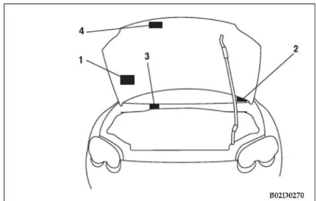
Keep a record of the chassis number and vehicle identification number as such information will assist the police if your vehicle is stolen.
1 - Vehicle emission control information label
The vehicle emission control information label is affixed on the underside panel of the engine hood.
2 -Vehicle identification number plate
This is stamped on the number plate riveted to the left front corner of the instrument panel pad. It is visible from outside of the vehicle through the windshield.
3 - Vehicle information code plate
The vehicle information code plate is located on the bulkhead inside the engine compartment.
4 - Air conditioner label
The air conditioner label is affixed on the inside panel of the engine hood.
5 - Engine serial number
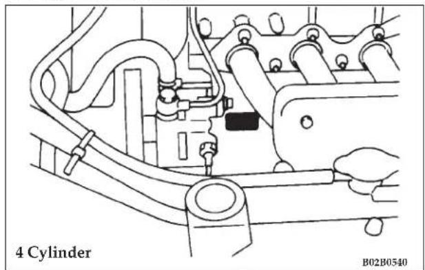
The engine serial number is stamped on the cylinder block as shown in the illustrations.
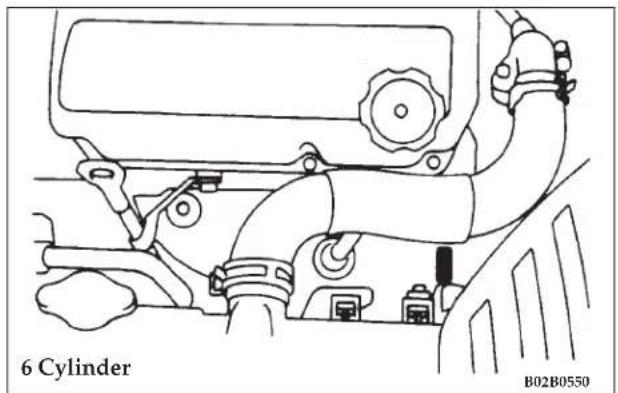
360 SPECIFICATIONS
6 - Tire and loading information placard
The tire inflation pressure label is located on the inside sill of the driver's door.
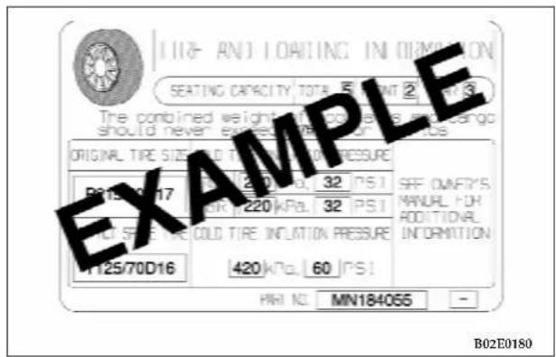
7 - Certification label
The certification label is located on the inside sill of the driver's door.
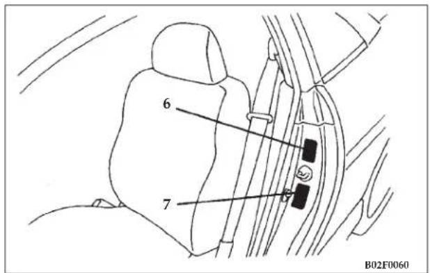
BATTERY
BCI Group NO.86
Battery is 12 volts.
NOTE: There are various size of the batteries in the BCI Group No.86.
When you replace a battery, check the size of the battery to prevent interfering with other parts in the engine compartment.
GENERAL VEHICLE DATA
| Overall length 191.9in (4,875mm) |
| Overall width 69.9in (1,775mm) |
| Overall height 53.9in (1,370mm) |
| Wheel base 103.7in (2,635mm) |
TIRES AND WHEELS
| Item 2.4 liter | 3.0 liter | |||
| LX LXi | ||||
| Tire | Type Radial, tubeless | |||
| Size P205/60R16 91H | P215/50R1790H | |||
| Spare tire T125/70D16 | ||||
| Wheel | Type Steel/Aluminum* Aluminum | |||
| Size 16x6JJ | 17x6 1/2JJ | |||
| PCD | 4.5 in. (114.3 mm) | |||
| Offset | 1.81 in. (46 mm) | |||
| Spare wheel | 16x4T | |||
VEHICLE WEIGHTS
| Item | 2.4 liter 3.0 liter | ||
| Gross vehicle weight rating | 4,061lb (1,842 kg) | 4,227lb (1,917 kg) | |
| Gross axle weight rating | Front | 2,171lb (985 kg) | 2,322lb (1,053 kg) |
| Rear | 1,894lb (859 kg) | 1,905lb (864 kg) | |
| Seating capacity | 5 persons | ||
| GVWR: maximum total weight(load) limit specified for the vehicle |
| GAWR: maximum weight(load) limit specified for the front or rear axle. |
| seating capacity: the number of maximum occupants |
| cargo capacity: weight subtracted 68 kilograms times the designated seating capacity from the vehicle capacity weight |
*: optional
CAUTION!
Do not use the gross vehicle weight rating data provided in the chart or on the safety certification label for determining vehicle passenger and/or cargo load capacity.
Use the values provided on the tire and loading information placard (Refer to the section "Vehicle labeling").
ENGINE SPECIFICATIONS
| Item Specifications | |||
| Engine model 4 Cylinder 6 Cylinder | |||
| Engine displacement 2,351dm | ^3 (143.4 CID) 2,972dm | ^3 (181.3 CID) | |
| No. of cylinders and cylinder arrangement 4 in-line 6 - V60 ° | |||
| Bore 86.5 mm (3.41 in) 91.1 mm (3.58 in) | |||
| Stroke 100 mm (3.94 in) 76.0 mm (2.99 in) | |||
| Compression ratio 9.0 9.0 | |||
| Controlled by-pass thermostat 88 °C (190 °F) 88 °C (190 °F) | |||
| Spark plugs | NGK | BKR5E-11 | FR5E1 |
| DENSO | K16PR-U11 | — | |
| CHAMPION | RC10YC4 | — | |
| Spark plug gap | 1.0 to 1.1 mm(.039 to .043 in ) | 0.7 to 0.8 mm(.028 to .031 in ) | |
| Firing order | 1-3-4-2 | 1-2-3-4-5-6 | |
| Ignition timing idle speed and mixture | Refer to the “Vehicle emission control information” label under the engine hood. | ||
NOTE
- Your engine is equipped with intake and exhaust valve auto-lash adjusters that require no adjustment.
- Your vehicle has one of the listed spark plugs. Use any one of the listed spark plugs for replacement.
CAPACITIES
| Item Capacity Recommended Lubricants | |||
| Fuel (approximate) 62dm | ^3 (16.3 gal) — | ||
| Engine oil Oil pan 4dm | ^3 (4.2 qt) Engine oils displayingILSAC certification symbolor conforming to the APIclassification SL, SL/CF | ||
| Oil filter 0.3dm | ^3 (0.32 qt) | ||
| Power steering 1.2dm | ^3 (1.3 qt) Diamond ATF | ||
| Automatic transaxle 4 Cyl.: 7.7dm | ^3 (8.2 qt)6 Cyl.: 8.4dm ^3 (8.9 qt) | Diamond ATF SPIII | |
| Manual transaxle 4 Cyl.: 2.2dm | ^3 (2.3 qt)6 Cyl.: 2.8dm ^3 (3.0 qt) | Gear oil API classificationGL-4 SAE 75W-85W or75W-90 | |
| Brakes and clutch As required Conforming | to Brake fluid | DOT3 or DOT4 | |
| Transaxle linkage, Parking brake cable mechanism, hoodlock and hook, door latches, seat adjusters | As required | Multipurpose grease NLGIGrade 2 | |
| Door hinges, trunk lid hinges | As required | Engine oil | |
| Engine coolant | 4 Cyl.-M/T: *8.0L (8.5 qt)-A/T: *7.9L (8.3 qt)6 Cyl.-M/T: *9.2L (9.7 qt)-A/T: *9.1L (9.6 qt) | Long Life Antifreeze Coolantor an equivalent | |
| Refrigerant (air conditioning) | 425g (15 oz) | HFC-134a | |
| Windshield washers 4 L (4.2 qt) — | |||
*: Include 0.65 L (.69 qt.) in reserve tank.
IF YOU NEED CONSUMER ASSISTANCE
CONTENTS
■ Suggestions For Obtaining Service For Your Vehicle .... 3 6 6
□ Prepare For The Appointment ..... 3 6 6
□ Prepare A List....366
□ Be Reasonable With Requests ..... 3 6 6
■ If You Need Assistance .... 3 6 6
■ Warranty Information .... 3 6 8
■ Mopar Parts 369
■ Customer Arbitration Board 369
■ Reporting Safety Defects ..... 3 6 9
□ In Canada 369
■ Publication Order Forms ..... 3 7 1
■ Department Of Transportation Uniform
Tire Quality Grades .... 3 7 3
□ Treadwear....373
□ Traction AA, A, B, C. 373
□ Temperature A, B, C. 374
SUGGESTIONS FOR OBTAINING SERVICE FOR YOUR VEHICLE
Prepare For The Appointment
If you're having warranty work done, be sure to have the right papers with you. Take your warranty folder. All work to be performed may not be covered by the warranty, discuss additional charges with the service manager. Keep a maintenance log of your vehicle's service history. This can often provide a clue to the current problem.
Prepare A List
Make a written list of your vehicle's problems or the specific work you want done. If you've had an accident, or work done that is not on your maintenance log, let the service advisor know.
Be Reasonable With Requests
If you list a number of items, and you must have your vehicle by the end of the day, discuss the situation with the service advisor and list the items in order of priority. At many dealers you may obtain a rental vehicle at a minimal daily charge. If you need a rental, it is advisable to make these arrangements when you call for an appointment.
IF YOU NEED ASSISTANCE......
DaimlerChrysler Motors Corporation and its dealers are vitally interested in your satisfaction. We want you to be happy with our products and services.
Your selling dealer is best equipped and most anxious to provide prompt resolution for any warranty issue or related matter that you may experience. DaimlerChrysler Motors Corporation dealers have the facilities, factory-trained technicians, special tools, and the latest information to assure your vehicle is fixed correctly and in a timely manner. DaimlerChrysler Motors Corporation has empowered its dealers to make warranty and repair decisions that ensure you are not inconvenienced. There is no need for you to wait for a decision from the DaimlerChrysler Motors Corporation. If a special circumstance occurs that requires information from DaimlerChrysler Motors Corporation, we have asked the dealer's service management to make the contact on your behalf.
This is why you should always talk to your dealer's service manager first. Most matters can be resolved with this process.
- If for some reason you are still not satisfied, talk to the general manager or owner of the dealership. They want to know if you need assistance.
- If your dealership is unable to resolve the concern, you may contact the DaimlerChrysler Motors Corporation Customer Center.
Any communication to the DaimlerChrysler Motors Corporation Customer Center should include the following information:
- Owner's name and address
- Owner's telephone number (home and office)
- Dealership name
• Vehicle identification number
• Vehicle delivery date and mileage
DaimlerChrysler Motors Corporation Customer
Center
P.O. Box 21-8004
Auburn Hills, MI 48321-8004
Windsor, Ontario N9A 4H6
Phone —Refer to your Warranty Booklet
In Mexico contact:
Lago Alberto #320
Mexico 11320, D. F.
In Mexico (915) 729–1248 or 729–1240
Outside Mexico (525) 729–1248 or 729–1240
Customer Assistance For The Hearing Or Speech Impaired (TDD/TTY)
To assist customers who have hearing difficulties, DaimlerChrysler Motors Corporation has installed special TDD (Telecommunication Devices for the Deaf) equipment at its Customer Center. Any hearing or speech impaired customer who has access to a TDD or a conventional teletypewriter (TTY) in the United States can communicate with DaimlerChrysler Motors Corporation by dialing 1-800-380-CHRY.
Service Contract
You may have purchased a service contract for your vehicle to help protect you from the high cost of unexpected repairs after your DaimlerChrysler Motors Corporation new vehicle limited warranty expires. DaimlerChrysler Motors Corporation stands behind only Genuine DaimlerChrysler Motors Corporation Service Contracts. If you purchased a Genuine DaimlerChrysler Motors Corporation Service Contract, you will receive Plan Provisions and an Owner Identification Card in the mail within three weeks of your vehicle delivery date. If you have any questions about your service contract, call the DaimlerChrysler Motors Corporation Service Contract National Customer Hotline at 1-800-521-9922.
DaimlerChrysler Motors Corporation will not stand behind any service contract that is not a Genuine DaimlerChrysler Motors Corporation Service Contract. It is not responsible for any service contract other than a Genuine DaimlerChrysler Motors Corporation Service Contract. If you purchased a service contract that is not a Genuine DaimlerChrysler Motors Corporation Service Contract, and you require service after your DaimlerChrysler Motors Corporation new vehicle limited warranty expires, please refer to your contract documents, and contact the person listed in those documents.
We appreciate that you have made a major investment when you purchased your new vehicle. Your dealer has also made a major investment in facilities, tools, and training to assure that you are absolutely delighted with your ownership experience. You'll be pleased with their sincere efforts to resolve any warranty issues or related concerns.
WARRANTY INFORMATION
See your DaimlerChrysler Motors Corporation Warranty Information Booklet for information on warranty coverage and transfer of warranty.
MOPAR PARTS
Mopar fluids, lubricants, parts, and accessories are available from your DaimlerChrysler Motors Corporation dealer. They will help you keep your vehicle operating at its best.
CUSTOMER ARBITRATION BOARD
In the 50 United States, and Washington, D.C., if a warranty dispute has not been resolved to your satisfaction, you may submit the issue to a DaimlerChrysler Motors Customer Arbitration Board.
Additional information and the address of each Customer Arbitration Board is contained in the Customer Arbitration Board Brochure included in the Glove Box Kit.
REPORTING SAFETY DEFECTS
In the 50 United States and Washington D.C.: If you believe that your vehicle has a defect which could cause a crash or cause injury or death, you should immediately inform the National Highway Traffic Safety Administration (NHTSA) in addition to notifying DaimlerChrysler Corporation.
If NHTSA receives similar complaints, it may open an investigation, and if it finds that a safety defect exists in a group of vehicles, it may order a recall and remedy campaign. However, NHTSA cannot become involved in individual problems between you, your dealer, and DaimlerChrysler Corporation.
To contact NHTSA, you may either call the Auto Safety Hotline toll free at 1-800-424-9393 (or 366-0123 in Washington DC area) or write to: NHTSA, U.S. Dept. of Transportation, Washington DC 20590. You can also obtain other information about motor vehicle safety from the Hotline.
In Canada:
If you believe that your vehicle has a safety defect, you should contact the Customer Service Department immediately. Canadian customers who wish to report a safety defect to the Canadian government should write to Transport Canada, P.O. Box 8880, Ottawa Postal Station, Ottawa, Ontario K1G 3J2.
370 IF YOU NEED CONSUMER ASSISTANCE
PUBLICATION ORDER FORMS
U.S. RESIDENTS ONLY To order the publications shown, tear out this page, fill in all information and mail to the address below. Enclose a check or money order payable to DaimlerChrysler. Visa and Mastercard orders are accepted by telephone. Please have your card and order information available when you call our distributor. Please allow 30 days. Prices subject to change without notice.
Dyment Distribution Services
P.O. Box 360450
Strongsville, OH 44136 1-800-890-4038
The toll-free number is not answered by DaimlerChrysler.
PLEASE TYPE OR PRINT
| Name | |
| Address | |
| City | |
| State | Zip |
| Date | |
| Amount of check or money order $ | |
☐ SERVICE MANUAL: \$110.00 + TAX Specify year, make and model (example: 2002 Dodge Caravan)
☐ OWNER'S MANUAL: \$10.00 + TAX Specify year, make and model (example: 2002 Dodge Caravan)
☐ DaimlerChrysler Child Seat instructions (if applicable) Specify year, make and model (example: 1997 Dodge Caravan)
Shipping and Handling: Purchase up to \40.00 add \4.00. Purchases over \$40.00 add 10% of the total order.
80ea318b
CANADIAN RESIDENTS ONLY
To order the publications shown, tear out this
page, fill in all information and mail to the address below. Enclose a cheque or money order payable to DaimlerChrysler Canada Inc. Visa and Mastercard orders are accepted by telephone. Please have your card and order information available when you call our distributor. Please allow 30 days.
Prices subject to change without notice.
Dyment Distribution Services
210 Wicksteed Ave.
Toronto, ON M4G 2C3 1-800-387-1143
The toll-free number is not answered by DaimlerChrysler.
PLEASE TYPE OR PRINT
| Name | |
| Address | |
| City | |
| Province | Postal Code |
| Date | |
| Amount of cheque or money order $ | |
☐ SERVICE MANUAL: \$110.00 + GST
English only. Specify year, make and model (example: 2002 Dodge Caravan)
☐ OWNER'S MANUAL: \$10.00 + GST Specify language ☐ English ☐ French and year, make and model:
☐ DaimlerChrysler Child Seat instructions (if applicable) Specify language ☐ English ☐ French and year, make and model:
GST Reg. No. R100963941
80ea318f
DEPARTMENT OF TRANSPORTATION UNIFORM TIRE QUALITY GRADES
The following describes the tire grading categories established by the National highway Traffic Safety Administration. The specific grade rating assigned by the tire's manufacturer in each category is shown on the sidewall of the tires on your car.
All Passenger Car Tires Must Conform to Federal Safety Requirements in Addition to These Grades.
Treadwear
The treadwear grade is a comparative rating based on the wear rate of the tire when tested under controlled conditions on a specified government test course. For example, a tire graded 150 would wear one and a half (1 1/2) times as well on the government course as a tire graded 100. The relative performance of tires depends upon the actual conditions of their use, however, and may depart significantly from the norm due to variations in driving habits, service practices and differences in road characteristics and climate.
Traction AA, A, B, C
The traction grades, from highest to lowest, are AA, A, B and C. Those grades represent the tire's ability to stop on wet pavement as measured under controlled conditions on specified government test surfaces of asphalt and concrete. A tire marked C may have poor traction performance.
WARNING!
The traction grade assigned to this tire is based on straight-ahead braking traction tests and does not include acceleration, cornering, hydroplaning, or peak traction characteristics.
374 IF YOU NEED CONSUMER ASSISTANCE
Temperature A, B, C
The temperature grades are A (the highest), B and C, representing the tire's resistance to the generation of heat and its ability to dissipate heat when tested under controlled conditions on a specified indoor laboratory test wheel. Sustained high temperatures can cause the material of the tire to degenerate and reduce tire life, and excessive temperature can lead to sudden tire failure. The grade C corresponds to a level of performance which all passenger vehicle tires must meet under the Federal Motor Vehicle Safety Standard No. 109. Grades B and A represent higher levels of performance on the laboratory test wheel than the minimum required by law.
WARNING!
The temperature grade for this tire is established for a tire that is properly inflated and not overloaded. Excessive speed, under-inflation, or excessive loading, either separately or in combination, can cause heat build-up and possible tire failure.
INDEX
376 INDEX
Accessory boxes 211
Accessory (installation) 246
Adding Fuel 145
Air cleaner filter 310
Air conditioning 234
Aluminum wheel 255
Antenna 217
Anti-lock braking system warning light . . . . 105,111
Assist-starting procedures if battery is low . . . . 2 7 5
Automatic transaxle indicator ..... 1 1 7
Automatic transaxle oil temperature warning light 105
Automatic transaxle Automatic transaxle fluid .... 3 2 1
Driving speed 155
Gear positions....154
Holding on an upgrade....163
Oil temperature warning light . . . . . . . . . . 1 0 5
Parking....167
Reset Mode....156,164
Selector lever operation....1 5 1
Automatic transmission....156
Autostick....161
Ball joint, steering linkage seal and drive
shaft boots 323
Battery 319
Charging system warning light . . . . . . . 105,112
During cold weather 200
Specification 360
Brake pad wear alarm....170
Brake System....170 Fluid....317
Hose 323
Parking brake 167,326
Pedal 169
Power brakes....170
Warning light 115
Warning sound for brake pad wear ..... 1 7 0
Brake Parking brake....3 2 6 Pedal....1 6 9
Break-in recommendations 142
Bulb chart 289,290
Car preparation before driving ..... 1 9 7
Cargo loads 3 3 1
INDEX 377
Cassette Tape and Player Maintenance ..... 2 2 2
Cassette Tape Player 217,219
CD Player 217,225
Center console 213
Center console box 211
Charging system warning light....105,112
Check engine/malfunction indicator lamp. 105,113
Child restraint....74
Clean Air Gasoline 143
Cleaning Exterior of your car ..... 2 5 0 Interior of your car ..... 2 4 9
Clock....214
Compact spare tire 263,361
Contract, Service 368
Coolant (engine) 316
Cruise control (for non-turbo) Indicator 105,111
Cruise control (for turbo) Indicator....105,111
Cup holder 210
Customer Arbitration Board 369
Customer Assistance 366
Dealer Service 366
Defroster (rear window)....1 2 3
Diagnostic System, Onboard 308
Dimmer control 120
Disc brake pads 323
Dome light 299
Dome light/Reading light 127
Door hinges, rear hatch hinges, hood lock
release mechanism and safety catch 324
Door Opener, Garage 130
Door-ajar warning light 105,110
Doors
Lock....26
Power door locks 34
Drive belt 327
Driving, alcohol and drugs 199
Driving speed
Automatic transaxle 155
Manual transaxle 167
Electric rear window defroster switch ..... 1 2 3
Emission-control system maintenance ..... 3 0 7
Engine compartment 255,305
378 INDEX
Engine coolant....3 1 6
Engine coolant level warning light ..... 1 0 5
Engine coolant temperature gauge ..... 104,109
Engine hood release 41
Engine oil and oil filter 312
Engine overheating 274
Engine serial number 359
Engine specifications....363
Exhaust system....324,363
Fluid
Automatic transaxle fluid . . . . . . . . . . . . . . 3 2 1
Brake fluid 317
Clutch fluid 318
Fog light switch 121
Front fog lamp indicator lamp 1 1 2
Front seat adjustment 5 5
Fuel
Filler Cap 146
Fuel economy....147
Fuel filler 39
Fuel gauge....104,107
Fuel hoses 309
Fuel selection....142
Low-fuel warning light 105,111
Fuses 282
Fusible links 283
Garage Door Opener 130
Gas Cap 146
Gasoline/Oxygenate Blends....144
Gauges 104,107,109
Gear positions 154
General maintenance
Maintenance service 312
General vehicle data 361
Glove compartment 211,212
Handling of Compact Discs....230
Hazard warning flasher switch ..... 1 2 2
Hazard warning light....105,110
Head restraints....6 4
Headlights (Type 1)....290
Headlights (Type 2)....291
Headlights
Aiming 293
INDEX 379
Dimmer....120
Headlight flasher (high/low beam) ..... 1 1 9
Switch....118
Heater 234
High beam indicator....105,110
High-mounted stoplights
Bulb capacity 288
Homelink Transmitter....130
Horn switch....130
Ignition switch 147
Indicator and warning light . . . . . . . . . . . . . . . 1 0 5
Inside day/night rearview mirrors ..... 175
Instrument cluster 104
Instrument panel light dimmer control ..... 1 2 3
Intermittent Wipers 125
Jack
Jacking points 266
Jacking up the car 266
Storage 262
Key reminder chime ..... 1 4 8
Keyless entry system 29
Keys 23,148
Labeling 358
Lap Belts 85
Lights
Bulb chart....289
Dome light/Reading light 127
Headlights....1 1 8
Reading lamps 129
Low-fuel warning light . . . . . . . . . . . . . . . . 105,111
Luggage hooks 213
Malfunction Indicator Light 308
Manual, Service 371
Manual transaxle
Oil 323
Possible driving speed 167
Shift points (recommended speed) ..... 1 6 5
Meters 104
Mirrors
Vanity mirror 209
Mopar Parts 309,369
380 INDEX
Odometer 104,108
Oil pressure gauge 104
Oil pressure warning light....105,112
Oil
Engine oil 312
Onboard Diagnostic System 308
Opener, Garage Door 130
Operation during cold weather 200
Operation under adverse driving conditions . . . 259
Overdrive indicator 105
Oversize tires 330
Owner's Manual 371
Parking brake
Operating method 167
Parking brake lever stroke....3 2 6
Polishing 254
Power brakes 170
Power door locks 34
Power windows 43
Proper shift points ..... 1 6 5
Puncture (tire changing) 270
Radial ply tires....3 3 0
Radiator cap 305,316,317
Radio 217
General information 214
Reading lamps 129
Reading light 129
Rear seats 64
Rear window defroster 123
Replacement of light bulbs 288
Reporting Safety Defects 369
Safe driving techniques 198
Scheduled maintenance 3 3 4
Seat belt extender 73
Seat Belts
Adjustable seat belt anchor ..... 71,78
And Pregnant Women 85
Child restraint 74
Maintenance and inspection 86
Seat belt extender 73
Seat belt reminder/warning light 105
UNIBELT restraint system....67
INDEX 381
Seatback 58
Seats
Front seats 5 5
Rear seats 64
SECURITY indicator ..... 48,105,110
Service Assistance 366
Service Manuals 371
Setting the clock 214
Severe maintenance schedule ..... 3 4 3
Snow tires 333
Spare tire 262,263,361
Spark plugs 3 1 1,363
Speedometer....104,106
Starting
At extremely cold ambient temperature ..... 1 5 1
Flooded engine 151
Normal conditions 150
Steering system
Steering lock 149
Tilt lock lever 173
Sunvisors 207
Sunroof 45
Supplemental Restraint System - Airbag
Maintenance....3 2 3
Warning light 105,114
Supplemental Restraint System (SRS) - Air bag . . 87
Supplemental Restraint System warning light .. 114
Tachometer 104,106
Tape Player 217
Temperature Gage, Engine Coolant ..... 275
Theft protection....149
Theft-alarm
SECURITY indicator ..... 48,105,110
System 48
Timing belt 328
Tips for driving in various conditions ..... 1 9 9
Tire chains 333
Tires
Compact spare tire 263
Inflation pressure 328,360,361
Maintenance 328,331
Quality Grading 373
Rotation 332
Size (tire and wheels) 361
382 INDEX
Snow tires 333
Spare tire 262
Tire chains 3 3 3
Tread wear indicators 3 3 1
Tools 262
Towing 280
Trailering 201
Trailer Towing 201
Transaxle
Automatic transaxle 151
Autostick....161
Manual transaxle....164
Transmission
Automatic transmission....156
Transmitter, Garage Door Opener ..... 1 3 0
Transporting Pets 100
Trip odometer....104
Trip odometer reset button 104
Trunklid
Turbocharger boost gauge 104
Turn signal indicators ..... 105,110
Lever....120
Uniform Tire Quality Grades 373
Universal Transmitter 130
Vanity mirror 207
Vehicle Identification Number 5
Vehicle labeling 358
Vehicle Weights 361
Ventilators 233
Warnings and Cautions 5
Warranty Information 368
Washer fluid level indicator....105
Washer
Windshield 126,325
Washing 251
Waxing 253
Wheel covers 264
Whip antenna 217
3 5Windshield washers ..... 126,325
Windshield wiper blades 325
Windshield wipers 124


- HOW TO USE THIS MANUAL
- WARNINGS, CAUTIONS AND NOTES
- VEHICLE IDENTIFICATION NUMBER
- WARNING!
- INTRODUCTION
- Overview - Instruments and controls
- Interior
- INTRODUCTION
- Outside
- Trunk Area
- INTRODUCTION
- QUICK INDEX
- INTRODUCTION
- INTRODUCTION
- INTRODUCTION
- INTRODUCTION
- LOCKING AND UNLOCKING
- CONTENTS
- LOCKING AND UNLOCKING
- KEYS
- SENTRY KEY
- LOCKING AND UNLOCKING
- NOTE
- CAUTION!
- Replacement keys
- NOTE:
- Customer Key Programming
- LOCKING AND UNLOCKING
- General Information
- DOOR LOCKS (MANUAL)
- Key reminder chime
- Forgotten-key prevention mechanism
- Door-ajar warning chime
- LOCKING AND UNLOCKING
- KEYLESS ENTRY SYSTEM
- To lock the doors
- To unlock the doors
- To unlock the trunk lid
- Confirmation function
- Horn deactivation/reactivation
- Turn signal light feature-ON/OFF
- Using the panic alarm
- LOCKING AND UNLOCKING 31
- LOCKING AND UNLOCKING
- Coin type battery CR2032 used
- LOCKING AND UNLOCKING
- POWER DOOR LOCKS
- Locking and unlocking with the door lock switch
- Rolling lock feature
- Locking and unlocking with key or inside lock knob
- Locking by means of the inside lock knob
- TRUNK LID
- LOCKING AND UNLOCKING
- To open the trunk lid
- To close the trunk lid
- Trunk-ajar warning chime
- Remote trunk lid release
- Inside emergency trunk release
- LOCKING AND UNLOCKING
- LOCKING AND UNLOCKING
- Low fuel warning chime
- LOCKING AND UNLOCKING
- POWER WINDOWS
- LOCKING AND UNLOCKING
- To tilt up
- LOCKING AND UNLOCKING
- To tilt down
- To open
- To close
- Sunshade
- LOCKING AND UNLOCKING
- THEFT-ALARM SYSTEM
- Armed stage
- LOCKING AND UNLOCKING
- Alarm stage
- Alarm deactivation
- Disarmed stage
- LOCKING AND UNLOCKING
- Testing the theft-alarm system
- SEATS, SEAT BELTS, CHILD RESTRAINTS AND AIR BAGS
- SEATS, SEAT BELTS, CHILD RESTRAINTS AND AIR BAGS
- SEATS, SEAT BELTS, CHILD RESTRAINTS AND AIR BAGS
- To adjust seat forward or backward
- SEATS, SEAT BELTS, CHILD RESTRAINTS AND AIR BAGS 57
- SEATS, SEAT BELTS, CHILD RESTRAINTS AND AIR BAGS 59
- Memory reclining knob
- To adjust seat height (Driver's side only)
- SEATS, SEAT BELTS, CHILD RESTRAINTS AND AIR BAGS 61
- Type 2 (Power, driver's side only-if so equipped)
- To adjust lumbar support (Driver's side only, if so equipped)
- SEATS, SEAT BELTS, CHILD RESTRAINTS AND AIR BAGS 63
- For access to the rear seat (passenger side entry)
- REAR SEATS
- Rear seat capacity
- Fold down rear seatbacks
- HEAD RESTRAINTS
- Adjustment of the head restraints
- SEAT BELTS
- UNIBELT restraint system
- UNIBELT instructions
- SEATS, SEAT BELTS, CHILD RESTRAINTS AND AIR BAGS
- SEATS, SEAT BELTS, CHILD RESTRAINTS AND AIR BAGS
- Enhanced Driver Seat Belt Use Reminder System (BeltAlert™)
- SEATS, SEAT BELTS, CHILD RESTRAINTS AND AIR BAGS
- SEATS, SEAT BELTS, CHILD RESTRAINTS AND AIR BAGS 79
- SEATS, SEAT BELTS, CHILD RESTRAINTS AND AIR BAGS 81
- SEATS, SEAT BELTS, CHILD RESTRAINTS AND AIR BAGS 83
- Children who have outgrown child restraint systems
- Seat Belts And Pregnant Women
- MAINTENANCE AND INSPECTION OF SEAT BELTS
- Supplemental Restraint System (SRS) - air bag
- SEATS, SEAT BELTS, CHILD RESTRAINTS AND AIR BAGS
- SRS servicing
- SEATS, SEAT BELTS, CHILD RESTRAINTS AND AIR BAGS 99
- Transporting Pets
- INSTRUMENTS AND CONTROLS
- INSTRUMENTS AND CONTROLS 103
- INSTRUMENTS AND CONTROLS
- Meter cluster
- Indicator and warning light package
- INSTRUMENTS AND CONTROLS
- Speedometer
- Tachometer
- INSTRUMENTS AND CONTROLS
- Odometer/Trip odometer
- Reset button
- Engine coolant temperature gauge
- INSTRUMENTS AND CONTROLS
- Turn signal indicators/hazard warning lights
- High beam indicator
- Theft-alarm indicator
- Door-ajar warning light and chime
- Trunk-ajar warning light and chime
- Anti-lock braking system warning light (if so equipped)
- ANTI LOCK
- Cruise/speed control indicator
- CRUISE
- Low-fuel warning light and chime
- INSTRUMENTS AND CONTROLS
- Front fog light indicator
- Charging system warning light
- Oil pressure warning light
- Malfunction indicator light (SERVICE ENGINE SOON)
- SERVICE ENGINE SOON
- Overheating warning light
- Supplemental Restraint System (SRS)-air bag warning light
- SRS
- Brake warning light
- Seat belt reminder/warning light
- Changing the setting for warning operation
- Automatic transaxle indicator (if so equipped)
- Traction Control System warning light (if so equipped)
- TCS
- Washer fluid level indicator
- INSTRUMENTS AND CONTROLS
- COMBINATION HEADLIGHTS, DIMMER AND TURN SIGNAL LEVER
- Light auto-cutout feature (headlights, fog lights, etc.)
- When you want to keep the lights on (time delay):
- Headlight reminder chime
- INSTRUMENTS AND CONTROLS
- Dimmer (high/low beam change)
- INSTRUMENTS AND CONTROLS
- INSTRUMENTS AND CONTROLS
- WINDSHIELD WASHER
- PRECAUTIONS TO OBSERVE WHEN USING WIPERS AND WASHERS
- DOME LIGHT
- INSTRUMENTS AND CONTROLS
- LIGHTS (DOME LIGHTS, ETC.) AUTO-CUTOUT FUNCTION
- READING LIGHTS
- INSTRUMENTS AND CONTROLS
- GARAGE DOOR OPENER (IF SO EQUIPPED)
- Training The Universal Transceiver
- INSTRUMENTS AND CONTROLS
- Canadian Programming/Gate Programming
- INSTRUMENTS AND CONTROLS
- Operation
- "Rolling Code" Programming
- Reprogramming A Signal Button
- INSTRUMENTS AND CONTROLS
- Security
- STARTING AND DRIVING
- STARTING AND DRIVING
- STARTING AND DRIVING 141
- STARTING AND DRIVING
- BREAK-IN RECOMMENDATIONS
- FUEL SELECTION
- Gasoline additives
- Octane requirement
- liter engine model
- liter engine model
- Reformulated Gasoline
- STARTING AND DRIVING
- Gasoline/Oxygenate Blends
- MMT in Gasoline
- Sulfur in Gasoline
- Materials Added to Fuel
- Adding Fuel
- STARTING AND DRIVING
- Fuel Filler Cap (Gas Cap)
- FUEL ECONOMY
- LOCK
- STARTING AND DRIVING
- ACC
- START
- ON
- THEFT PROTECTION
- STEERING LOCK
- STARTING
- Tips for starting
- Normal conditions
- Flooded engine
- At extremely cold ambient temperature
- AUTOMATIC TRANSAXLE (IF SO EQUIPPED)
- DRIVING UPHILL
- DRIVING DOWNHILL
- STARTING AND DRIVING
- Selector lever operation
- STARTING AND DRIVING
- Gear positions
- "P" PARK
- "R" REVERSE
- "N" NEUTRAL
- "D" DRIVE
- "3" THIRD / "2" SECOND
- "L" LOW
- Driving speed (Vehicles with automatic transaxle)
- Holding on an upgrade
- STARTING AND DRIVING
- Transaxle Reset Mode
- AUTOMATIC TRANSAXLE AUTOSTICK (IF SO EQUIPPED)
- Selector positions (Main gate)
- P-PARK
- R - REVERSE
- Selector positions Manual gate Autostick
- STARTING AND DRIVING
- To start
- Proper shift points
- Upshifting
- Downshifting
- Driving precautions
- PARKING BRAKE
- STARTING AND DRIVING
- BRAKE PEDAL
- STARTING AND DRIVING
- POWER BRAKES
- BRAKE PAD WEAR ALARM
- ANTI-LOCK BRAKING (ABS) SYSTEM (IF SO EQUIPPED)
- General driving hints (standard/anti-lock brakes)
- STARTING AND DRIVING
- STARTING AND DRIVING
- POWER STEERING
- STARTING AND DRIVING
- Electrochromic inside rearview mirror (if so equipped)
- Electrochromic mirror operation (if so equipped)
- STARTING AND DRIVING
- How to change the display mode
- STARTING AND DRIVING
- STARTING AND DRIVING
- Compass operation
- Magnetic variation of compass
- To adjust for magnetic variation of compass
- STARTING AND DRIVING
- STARTING AND DRIVING
- Cleaning of the mirror
- STARTING AND DRIVING
- To activate
- STARTING AND DRIVING
- To decrease the set speed
- STARTING AND DRIVING
- WARNING
- STARTING AND DRIVING
- TRACTION CONTROL (IF SO EQUIPPED)
- Driving hints
- CATALYTIC CONVERTER
- VEHICLE PREPARATION BEFORE DRIVING
- Seat belts and seats
- Defrosters
- Tires
- STARTING AND DRIVING
- Lights
- Fluid leaks
- Driver
- SAFE DRIVING TECHNIQUES
- DRIVING, ALCOHOL AND DRUGS
- NEVER DRINK AND DRIVE.
- TIPS FOR DRIVING IN VARIOUS CONDITIONS
- STARTING AND DRIVING
- OPERATION DURING COLD WEATHER
- TRAILER TOWING
- Warranty Requirements
- STARTING AND DRIVING
- Weight limits
- FOR PLEASANT DRIVING
- FOR PLEASANT DRIVING
- FOR PLEASANT DRIVING 205
- FOR PLEASANT DRIVING
- SUN VISORS
- To adjust the sun visor position
- Vanity mirror
- FRONT SEAT
- REAR SEAT
- FOR PLEASANT DRIVING
- FOR PLEASANT DRIVING
- ELECTRONIC DIGITAL CLOCK
- Clock setting procedure
- GENERAL INFORMATION ABOUT YOUR RADIO
- Signal transmission
- Weak reception (fading)
- FOR PLEASANT DRIVING
- FM stereo reception
- Operating Instructions - Radio Mode
- FOR PLEASANT DRIVING
- Power Switch, Volume Control
- Seek Button (Radio Mode)
- Tuning
- Balance
- Fade
- Graphic Equalizer
- AM/FM Selection
- Scan Button
- To Set The Radio Pushbutton Memory
- To Change From Clock To Radio Mode
- Tape Player Operation
- FOR PLEASANT DRIVING
- Seek Button
- Fast Forward (FF)
- Rewind (RW)
- Tape Eject
- Changing Tape Direction
- Metal Tape Selection
- Pinch Roller Release
- Noise Reduction
- Operation Instructions — CD Player
- Inserting The Compact Disc
- EJT CD (Eject) Button
- FF/TUNE/RW Button
- FOR PLEASANT DRIVING
- Program Button 4 (Random Play)
- Tape /CD Button
- Time Button
- CASSETTE TAPE AND PLAYER MAINTENANCE
- AM/FM STEREO RADIO WITH 4 DISC CD CHANGER (IF SO EQUIPPED)
- FOR PLEASANT DRIVING
- Tone Control
- MODE Selection
- PTY (Program Type) Selection
- To Set The Pushbutton Memory
- Operating Instructions — CD Changer
- FOR PLEASANT DRIVING
- FF /TUNE/ RW Button
- Random Play
- Radio/CD Button
- Loading the CD Changer
- Playing Discs
- Removing Discs from the CD Changer
- STEERING WHEEL REMOTE CONTROL SWITCHES (IF SO EQUIPPED)
- FOR PLEASANT DRIVING
- How to adjust the volume
- To listen to the audio system
- To listen to the radio
- To select AM/FM mode
- Automatic tuning the radio
- To select the preset memory
- To listen to a tape
- To operate the APS (Automatic Program Sensor) system
- To listen to a CD
- To select CD mode
- To select a desired track
- To select a desired disc (CD autochanger only)
- Handling of Compact Discs
- FOR PLEASANT DRIVING
- Air flow rate and direction adjustments
- FOR PLEASANT DRIVING
- AIR CONDITIONING
- Control panel
- FOR PLEASANT DRIVING
- FOR PLEASANT DRIVING
- Air conditioning switch
- FOR PLEASANT DRIVING
- How to use the controls
- Heating
- Defrosting or defogging of the windshield and door windows
- FOR PLEASANT DRIVING
- Combination of unheated air and heated air
- Cooling
- Important operation tips for air conditioning
- Air conditioning system refrigerant and lubricant recommendations
- During a long period of disuse
- INSTALLATION OF ACCESSORIES
- VEHICLE CARE
- VEHICLE CARE
- CLEANING THE INSIDE OF YOUR VEHICLE
- Plastic, vinyl leather, fabric, and flocked parts
- Upholstery
- VEHICLE CARE
- Genuine leather (if so equipped)
- CLEANING THE OUTSIDE OF YOUR VEHICLE
- Foreign material
- Washing
- During cold weather
- Waxing your vehicle
- VEHICLE CARE
- Polishing your vehicle
- Damaged paint
- Cleaning plastic parts
- Chrome parts
- Aluminum wheels (if so equipped)
- Window glass
- Wiper blades
- Cleaning the sunroof (if so equipped)
- Engine compartment
- EMERGENCIES
- EMERGENCIES
- IF THE VEHICLE BREAKS DOWN
- If the engine quits
- OPERATION UNDER ADVERSE DRIVING CONDITIONS
- If your vehicle becomes stuck in sand, mud or snow
- On a wet road
- On snowy or icy roads
- Jack
- To remove
- To store
- COMPACT SPARE TIRE
- WHEEL COVERS (IF SO EQUIPPED)
- EMERGENCIES
- JACKING AND TIRE CHANGING
- Jacking up the vehicle
- EMERGENCIES
- ENGINE OVERHEATING
- JUMP-STARTING THE ENGINE
- EMERGENCIES
- EMERGENCIES
- If your vehicle has anti-lock brakes
- TOWING
- Towing—front wheel lift
- Towing—rear wheel lift
- EMERGENCIES
- Fuse block
- FUSIBLE LINKS
- Passenger compartment fuse location
- Spare fuse location
- Engine compartment Fuse location table
- REPLACEMENT OF LIGHT BULBS
- Bulb capacity
- EMERGENCIES
- Headlights (Type 1)
- Headlights (Type 2)
- EMERGENCIES
- Adjustment of headlight aim
- EMERGENCIES
- Front fog lights
- EMERGENCIES
- Rear combination lights
- EMERGENCIES
- Trunk light
- Type 1
- EMERGENCIES
- Remove the light bulb from the light holder. Reading lights
- Rear personal light
- MAINTENANCE
- MAINTENANCE
- VIEW OF ENGINE COMPARTMENT
- MAINTENANCE
- SERVICE PRECAUTIONS
- MAINTENANCE
- EMISSIONS TESTING
- ONBOARD DIAGNOSTIC SYSTEM (OBD II)
- REPLACEMENT PARTS
- Fuel system (tank, filler tube, connections, and fuel tank filler cap)
- Fuel hoses
- MAINTENANCE
- Air cleaner filter
- Evaporative emission control system (except evaporative emission canister)
- Spark plugs
- Ignition cables
- Distributor cap and rotor
- MAINTENANCE
- GENERAL MAINTENANCE
- Engine oil and oil filter
- To check and refill engine oil
- MAINTENANCE
- To replace the oil filter
- Engine oil identification mark
- MAINTENANCE
- ENGINE COOLANT
- To check the coolant level
- To add coolant
- Radiator cap
- Points to remember
- BRAKE FLUID
- To check the clutch fluid
- To replace the fluid
- BATTERY
- Disconnection and connection
- MAINTENANCE
- To check the fluid level
- Procedure for checking the fluid level
- Special additives
- MANUAL TRANSAXLE
- BRAKE HOSES
- BALL JOINT, STEERING LINKAGE SEAL AND DRIVE SHAFT BOOTS
- SUPPLEMENTAL RESTRAINT SYSTEM (SRS)
- MAINTENANCE
- DOOR HINGES, REAR HATCH HINGES, HOOD LOCK RELEASE MECHANISM AND SAFETY CATCH
- EXHAUST SYSTEM
- Check for any of the following conditions:
- WINDSHIELD WIPER BLADES
- MAINTENANCE
- DRIVE BELT (FOR GENERATOR, WATER PUMP, POWER STEERING PUMP)
- MAINTENANCE
- TIMING BELT
- Tire inflation pressures
- Safety
- Economy
- Ride comfort and vehicle stability
- MAINTENANCE
- Radial ply tires
- Tire pressure for sustained high-speed driving
- Oversize tires
- Tire maintenance
- Cargo loads
- MAINTENANCE
- Tire chains
- Snow tires
- MAINTENANCE
- REGULAR MAINTENANCE SCHEDULE
- 12,000 Miles (19 000 km) or at 12 months
- 18,000 Miles (29 000 km) or at 18 months
- 24,000 Miles (38 000 km) or at 24 months
- MAINTENANCE
- 30,000 Miles (48 000 km) or at 30 months
- 36,000 Miles (58 000 km) or at 36 months
- 42,000 Miles (67 000 km) or at 42 months
- 54,000 Miles (86 000 km) or at 54 months
- 48,000 Miles (77 000 km) or at 48 months
- 60,000 Miles (96 000 km) or at 60 months
- 66,000 Miles (106 000 km) or at 66 months
- 78,000 Miles (125 000 km) or at 78 months
- 72,000 Miles (115 000 km) or at 72 months
- 84,000 Miles (134 000 km) or at 84 months
- 90,000 Miles (144 000 km) or at 90 months
- 96,000 Miles (154 000 km) or at 96 months
- 102,000 Miles (163 000 km) or at 102 months
- 108,000 Miles (173 000 km) or at 108 months
- 114,000 Miles (183 000 km) or at 114 months
- 120,000 Miles (192 000 km) or at 120 months
- MAINTENANCE
- SEVERE MAINTENANCE SCHEDULE
- 3,000 Miles (5 000 km) or at 3 months
- 6,000 Miles (10 000 km) or at 6 months
- 9,000 Miles (14 000 km) or at 9 months
- MAINTENANCE
- 15,000 Miles (24 000 km) or at 15 months
- 21,000 Miles (34 000 km) or at 21 months
- 27,000 Miles (43 000 km) or at 27 months
- MAINTENANCE
- 33,000 Miles (52 800 km) or at 33 months
- 39,000 Miles (62 000 km) or at 39 months
- 45,000 Miles (72 000 km) or at 45 months
- 51,000 Miles (82 000 km) or at 51 months
- MAINTENANCE
- 57,000 Miles (91 000 km) or at 57 months
- 60,000 Miles (96 000 km)
- 60,000 Miles (96 000 km) or at 48 months
- 63,000 Miles (100 000 km) or at 63 months
- MAINTENANCE
- 69,000 Miles (110 000 km) or at 69 months
- 75,000 Miles (120 000 km) or at 75 months
- 81,000 Miles (130 000 km) or at 81 months
- 87,000 Miles (139 000 km) or at 87 months
- MAINTENANCE
- 93,000 Miles (149 000 km) or at 93 months
- 99,000 Miles (158 000 km) or at 99 months
- 105,000 Miles (168 000 km) or at 105 months
- MAINTENANCE
- 111,000 Miles (178 000 km) or at 111 months
- 114,000 Miles (182 000 km) or at 114 months
- 117,000 Miles (187 000 km) or at 117 months
- MAINTENANCE
- SPECIFICATIONS
- - Vehicle emission control information label
- -Vehicle identification number plate
- - Vehicle information code plate
- - Air conditioner label
- - Engine serial number
- SPECIFICATIONS
- - Tire and loading information placard
- - Certification label
- IF YOU NEED CONSUMER ASSISTANCE
- SUGGESTIONS FOR OBTAINING SERVICE FOR YOUR VEHICLE
- Prepare For The Appointment
- Prepare A List
- Be Reasonable With Requests
- IF YOU NEED ASSISTANCE......
- Customer Assistance For The Hearing Or Speech Impaired (TDD/TTY)
- Service Contract
- WARRANTY INFORMATION
- MOPAR PARTS
- CUSTOMER ARBITRATION BOARD
- REPORTING SAFETY DEFECTS
- In Canada:
- PUBLICATION ORDER FORMS
- CANADIAN RESIDENTS ONLY
- DEPARTMENT OF TRANSPORTATION UNIFORM TIRE QUALITY GRADES
- Treadwear
- Traction AA, A, B, C
- IF YOU NEED CONSUMER ASSISTANCE
- Temperature A, B, C
- INDEX
- INDEX
- INDEX 377
- INDEX
- INDEX 379
- INDEX
- INDEX 381
- INDEX
Brand : Chrysler
Model : Sebring Coupe (2004)
Category : Automotive