
Prima APSP G6 - Audio Amplifier AUDISON - Free user manual and instructions
Find the device manual for free Prima APSP G6 AUDISON in PDF.


| Type of product | Plug & Sound car audio upgrade kit for VW Golf 6 |
| Kit components | AP 8.9 bit G6 amplifier, APBX G6 subwoofer (10"), AP 6.5 G6 woofers (6.5"), AP 1 SP tweeters (1"), APSP G6 Harness, speaker cables, mounting kits, damping panel |
| Amplifier type | 8-channel with bit Drive technology, DCC (Direct Cockpit Current), 7 pre-loaded presets |
| Amplifier power output | Front channels (bridge): 2 x 130 W RMS @ 4 Ω; Rear channels (stereo): 2 x 35 W RMS @ 4 Ω; Subwoofer channel (bridge): 1 x 130 W RMS @ 4 Ω |
| Subwoofer type | Passive closed-box, 10" (250 mm) speaker |
| Subwoofer power handling | 300 W peak, 100 W continuous (RMS) |
| Front speaker power handling | 300 W peak per channel, 100 W continuous (RMS) |
| Frequency response (front) | 60 Hz – 20 kHz |
| Frequency response (subwoofer) | 38 Hz – 350 Hz |
| Impedance (all speakers) | 4 Ω |
| Crossover type | Front: 2-way passive; Subwoofer: digital via amplifier |
| Vehicle compatibility | VW Golf 6 (left-hand and right-hand drive) |
| Installation time | Less than 2 hours (typical, varies with vehicle equipment) |
| Power supply | 12 V car battery; 30 A fuse included |
| Input connections | OEM headunit speaker-level (via APSP G6 Harness), optical TOSLINK (optional) |
| Output connections | 2 bridged pairs for front woofers/tweeters, 1 stereo pair for OEM rear speakers, 1 bridged pair for subwoofer |
| Presets | 7 presets: Flat, Left-hand Drive (Acoustic/Live/Rhythm), Right-hand Drive (Acoustic/Live/Rhythm), Overall Acoustic |
| Optional accessories | DRC/DRC-MP digital remote control, Bit Play HD media player, TOSLINK cables (1.5 m / 4.5 m), TOSLINK adapter, ECK DRC extension cable |
| Cleaning instructions | Use a dry cloth; avoid liquids and solvents |
| Safety notes | Prolonged exposure to high sound levels can damage hearing; ensure installation does not obstruct airbags or safety devices |
| Warranty | Refer to www.audison.eu or contact authorized dealer |
Frequently Asked Questions - Prima APSP G6 AUDISON
User questions about Prima APSP G6 AUDISON
0 question about this device. Answer the ones you know or ask your own.
Ask a new question about this device
Download the instructions for your Audio Amplifier in PDF format for free! Find your manual Prima APSP G6 - AUDISON and take your electronic device back in hand. On this page are published all the documents necessary for the use of your device. Prima APSP G6 by AUDISON.
USER MANUAL Prima APSP G6 AUDISON
5.1 Removing the finishing frame....9
5.2 Removing the 4 fastening screws 9
5.3 Extraction of the original car audio....9
- DISASSEMBLING THE CAR DOOR SILL AND COVERINGS FROM THE RIGHT SIDES....10
6.1 Removing the rear seat 10
6.2 Removing the right rear wheelhouse cover (5-door version)....11
6.3 Removing the right door sill completely 12
6.4 Removing the lower cover of the right pillar 13
6.5 Removing the right side covering of the dashboard....13
- DISASSEMBLING THE FRONT DOOR COVERING....14
7.1 Removing the front door panel 14
7.2 Removing the tweeter casing 15
- PASSING APSP G6 HARNESS CABLES 16
8.1 Passing the cable in the car radio's casing to the right of the dashboard....16
8.2 Passing the subwoofer power cable up to the left rear side of the boot 17
- INSTALLATION OF SUBWOOFER APBX G6....18
9.1 Installing the mounting kit....18
9.2 Installing APBX G6 in the car....19
9.3 APBX G6 installation completed....20
- INSTALLATION OF WOOFERS AP 6.5 G6 21
10.1 Removing original Woofers 21
10.2 APSP G6 SPEAKER CABLE connection to woofer AP 6.5 G6....22
10.3 Assembling the woofer into the casing....22
- INSTALLATION OF TWEETER AP 1 SP 23
11.1 Removing the original Tweeters from the casing....23
11.2 Installing the AP 1 SP MOUNTING KIT ....23
11.3 Installing AP 1 SP in the casing....24
- INSTALLATION OF AP 8.9 BIT G6 25
12.1 Install ASP (Automatic Speaker Presence) 25
12.2 APSP G6 HARNESS cable connection to AP 8.9 bit G6....25
12.3 Positioning AP 8.9 bit G6....25
- CONNECTION OF THE APSP G6 HARNESS CABLE TO THE ORIGINAL CAR RADIO 26
13.1 Connect the APSP G6 HARNESS cable 26
- REASSEMBLING ALL PARTS 26
14.1 Reassemble all parts of the vehicle by following the operations described in the disassembly section in reverse order....26
- OPTIONAL ACCESSORIES 27
15.1 DRC (Digital Remote Control)....27
15.2 DRC-MP (Digital Remote Control) 27
15.3 Bit Play HD 27
15.4 OP 1.5 TOSLINK OPTICAL CABLE 1.5 M / 59.05 IN....28
15.5 OP 4.5 TOSLINK OPTICAL CABLE 4.5 M / 177.16 IN....28
15.6 STA - F/F SOCKET TOSLINK ADAPTER....28
15.7 ECK DRC 28
- TROUBLESHOOTING 29
Introduction
Congratulations for having purchased one of our products. Your satisfaction is the sine qua non that our products must meet: the same satisfaction of anyone who wants to feel the thrill of a car radio. This manual was drawn up to provide important information required to install and use the system.
Before installing the devices, carefully read all the instructions in this manual, and the manuals regarding individual parts included in the relative packages. Failure to comply with these instructions can cause involuntary injury or damage to system's parts or the vehicle.
Warranty
For the warranty conditions, please visit www.audison.eu or contact your specialised Audison centre.
Safe sound
USE COMMON SENSE WHEN LISTENING TO THE RADIO. REMEMBER THAT PROLONGED EXPOSURE TO EXCESSIVE LEVELS OF SOUND PRESSURE CAN DAMAGE YOUR HEARING. SAFETY WHEN DRIVING MUST ALWAYS BE FIRST.
1. PRODUCT DESCRIPTION
APSP G6 was specifically designed for VW Golf 6(*) and comprises:
- An AP8.9 bit G6 amplifier equipped with bit Drive technology and integrated with 7 drive pre-set dedicated to VW Golf 6(*) designed by the Audison R&D team for "Plug&Sound" performance. The 7 "Drive preset" pre-loaded in the AP8.9 bit G6 memory enables you to use to product without PC connection. Pre-set is chosen based on the user's preferences. AP8.9 bit G6 is equipped with DCC-Direct Cockpit Current technology and is powered directly from the rear connector of the OEM source.
- An APBX G6 passive closed-box subwoofer, which contains a compact speaker APS 250. The box is specifically designed to be placed on the left side of the boot, and is very compact in size and is fixed to the car without drilling the chassis. The mounting kit and installation manual are in the package.
- A front two-way system that includes the AP 6.5 G6 woofers, AP 1 SP tweeters and specific crossovers, adapters to set up OEM for the speakers, connectors, and gaskets for perfect integration with the pillars.
- A complete set of special cables for the car and kit, designed with Plug&Sound technology to be connected to original car manufacturer connectors, without needing to change the original car cables.
- A special APSP G6 Harness that draws power of AP8.9 bit G6 directly from the rear connector of the OEM source.
The kit is designed to be installed on a VW Golf 6(*) in less than 2 hours; this time can vary according to the conditions and equipment of the vehicle.
WARNING: Before proceeding with installing, make sure the APSP G6 kit is compatible with the version of your

Golf.
the information and images contained in this manual are referred to the left-hand drive 5-door car.
Note: • All kit components have been designed to be attached to the manufacturer's original attachment points on the vehicle.
- Pay special care during the removal and insertion of the speakers' fixing rivets.
• Make sure all the gaskets supplied with the speakers are positioned correctly and are working perfectly.
• The connectors are fragile components and must be handled with care. - After installation and before restarting the system, make sure the equalization of the vehicle's radio is flat.
• Install the kit components by following the instructions to ensure they do not prevent airbags or other safety devices of air from working correctly. - Use suitable quality equipment to simplify, accelerate and achieve optimal installation.
These installation instructions are updated to revision 01. Additional documents can be downloaded from www.audison.eu. If there is a malfunction during installation of the kit, check the section regarding "TROUBLESHOOTING" at the end of this manual. If you have consulted the aforesaid section and are still unable to solve the problem, visit www.audison.eu or contact your Audison authorised, specialised centre or official assistance via email: support@elettromedia.it.
* Golf is a registered brand that is property of Volkswagen.
2. CONTENTS OF THE PACKAGE
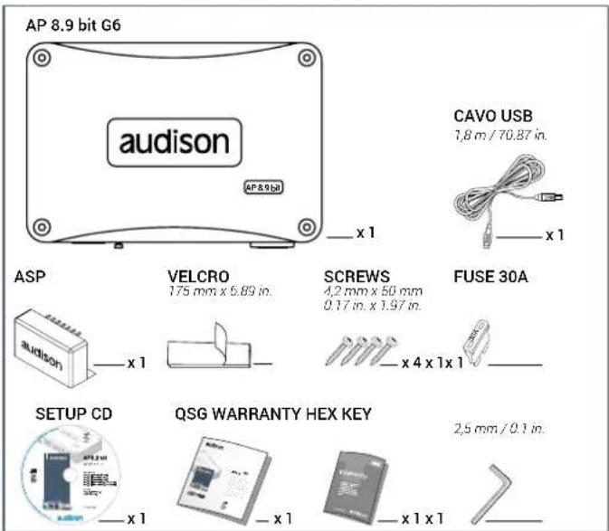
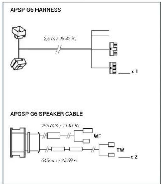
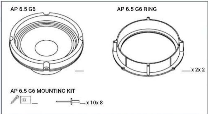
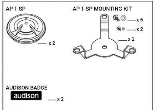
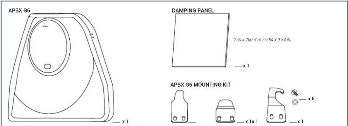
3. TECHNICAL SPECIFICATIONS
3.1 Preset description
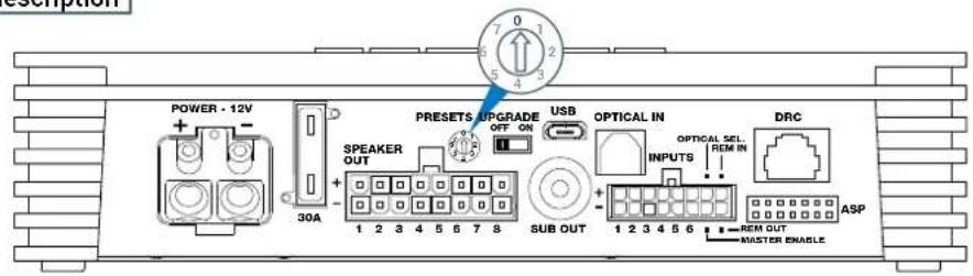
| PRESET | LISTENING POSITION | YOUR SOUND | DETAILS | |
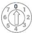 | Overall | FLAT | This preset only contains standard filters; no equalizations and no time alignments have been applied. | |
| WARNING: Preset '0" contains the input/output configurations dedicated to this speakers system.The "factory default" function loses the pre-loaded preset in "0". For this reason you must restore correct input/output setting via AP Prima PC software. It is recommended to backup the preset in your PC.Failure to comply with these recommendations can cause irreparable damage to AP8.9 bit G6 as well as products connected to it.DO NOT CHANGE PRESET WHEN THE PRODUCT IS ON. | ||||
 | Left Hand Drive | Acoustic | Detailed mid-high frequencies with perfectly balanced bass. Time alignment have been calibrated to ensure the best listening sensation for the driver (Left-hand drive cars). | |
 | Left Hand Drive | Live | Crisp mid-high frequencies and really dynamic bass.Time alignments have been calibrated to ensure the best listening sensation for the driver (Left-hand drive cars). | |
 | Left Hand Drive | Rhythm | Detailed mid-high frequencies with punchy bass. Time alignments have been calibrated to ensure the best listening sensation for the driver (Left-hand drive cars). | |
 | Right Hand Drive | Acoustic | Detailed mid-high frequencies with perfectly balanced bass. Time alignment have been calibrated to ensure the best listening sensation for the driver (Right-hand drive cars). | |
 | Right Hand Drive | Live | Crisp mid-high frequencies and really dynamic bass.Time alignments have been calibrated to ensure the best listening sensation for the driver (Right-hand drive cars). | |
 | Right Hand Drive | Rhythm | Detailed mid-high frequencies with punchy bass. Time alignments have been calibrated to ensure the best listening sensation for the driver (Right-hand drive cars). | |
 (default) (default) | Overall | Acoustic | Detailed mid-high frequencies with perfectly balanced bass. Time alignments have been set-up to guarantee the better listening feeling for everybody in the car. | |
TECHNICAL SPECIFICATIONS
| Component | APSP G6 - Front2 WAY SYSTEM | APBX G6SUBWOOFER | |
| Size mm (in.) | Woofer 165 (6.5)Tweeter 26 (1) | 250 (10) | |
| Power Handling | W (peak) 300 900W (continuos) | 100 | 300 |
| Impedance Ω | 4 4 | ||
| Frequency Response | Hz 60 ÷ 20k | 38-350 | |
| Crossover type | 2-Way passive | Digital | |
AP8.9 bit OUTPUT CHANNEL MAP
| Channel Mode | Speaker | Power | |
| 1-2 3-4 | Bridge | APSP G6 - Front | 2 x 130W RMS @ 4Ω |
| 5-6 | Stereo | OEM Rear Speakers | 2 x 35W RMS @ 4Ω |
| 7-8 | Bridge | APBX G6 - Subwoofer | 1 x 130W RMS @ 4Ω |
Notes:
- The AP 8.9 bit G6* is delivered with the selector set on pre-set "7" (Overall - Acoustic).
- You can install the "AP Prima PC Software" program in "Prima Amplifier Setup CD".
* Refer to the operating manual regarding AP8.9 bit for detailed information relating to installation and use of the "AP Prima PC Software". All materials are available from www.audison.eu.
4. CONNECTIONS LAYOUT
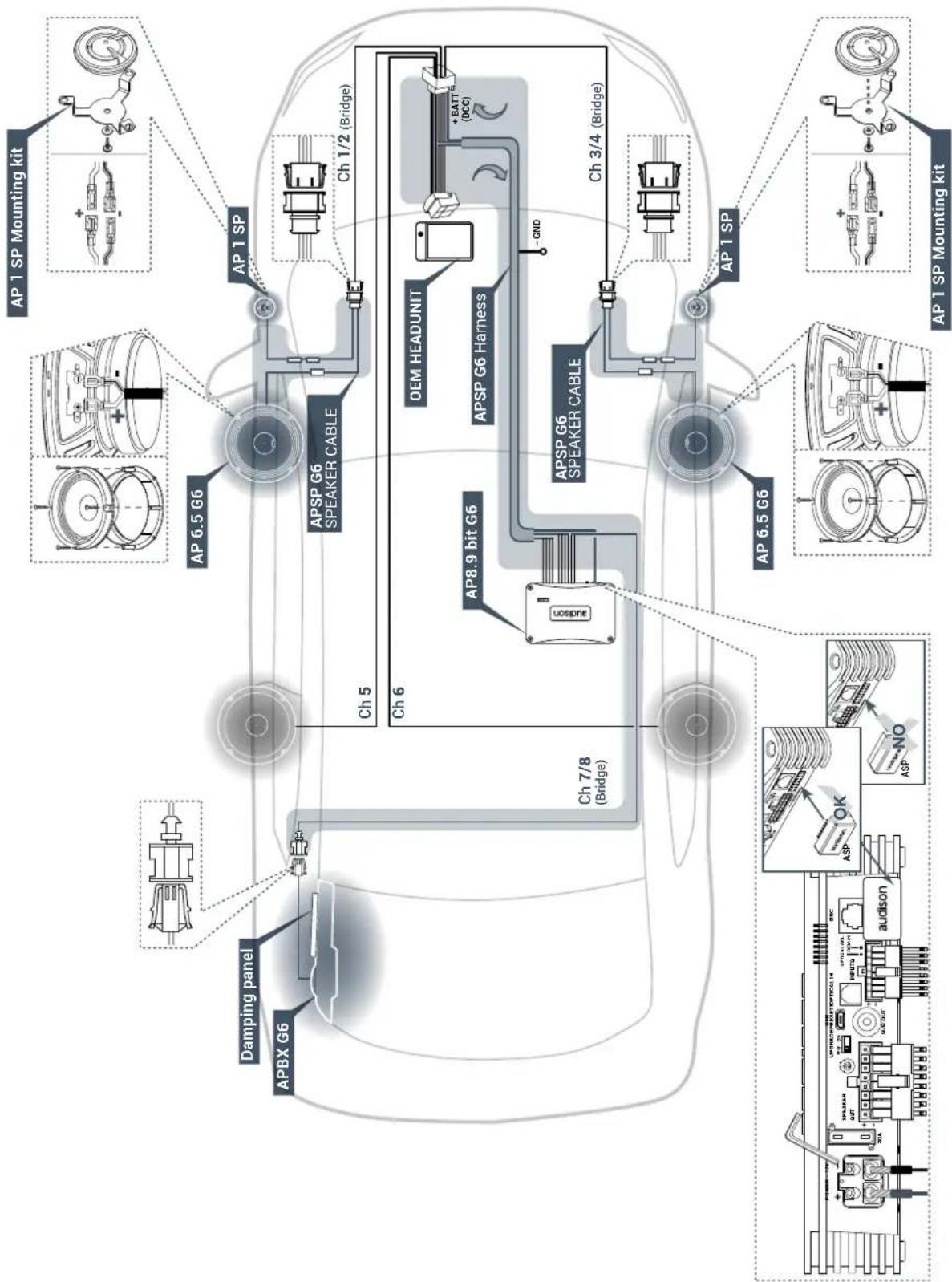
5. REMOVING THE ORIGINAL CAR RADIO
WARNING: Remove the key from the car's ignition and pull the lever to release the bonnet.
Close the doors and wait for 5 minutes, then open the bonnet and disconnect the negative pole from the car's battery.
5.1 Removing the finishing frame
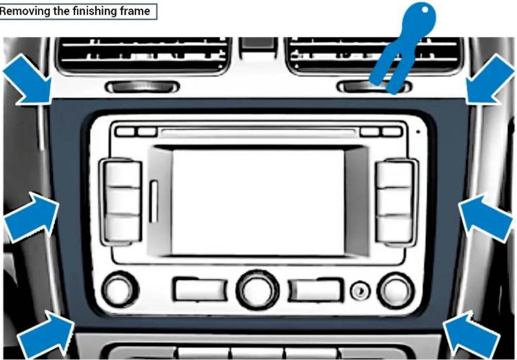
Fig. 1
5.2 Removing the 4 fastening screws
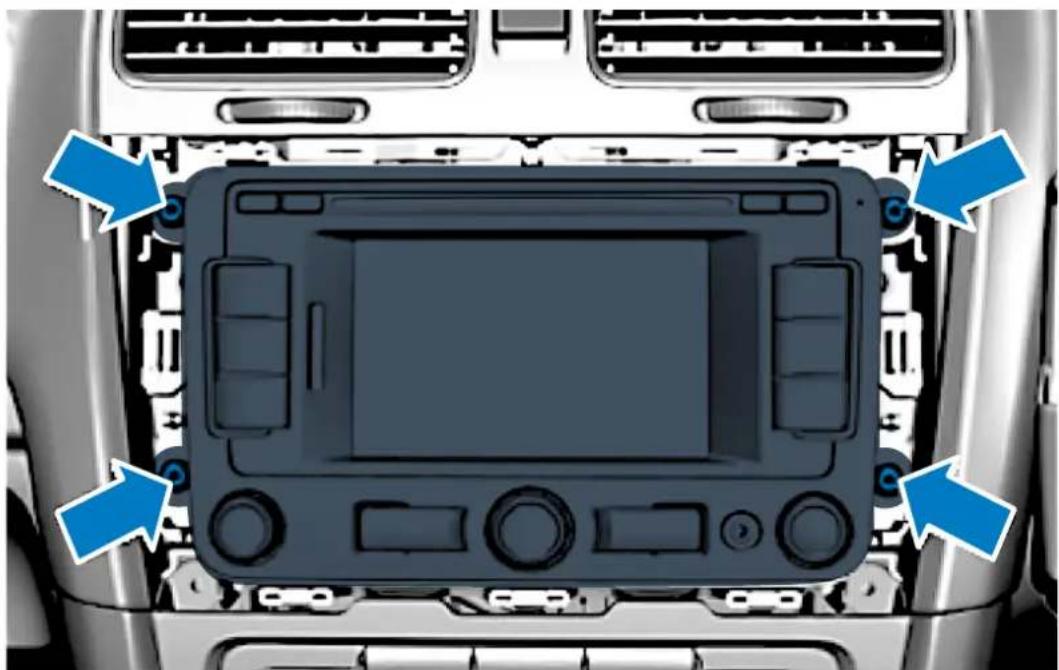
natural_image
Top-down view of a car's front dashboard and air conditioner unit (no text or symbols visible)Fig. 2
5.3 Extraction of the original car radio
5.3.1 disconnecting all connectors from the rear.
6. REMOVING THE DOOR SILL AND COVERINGS FROM THE RIGHT SIDE
WARNING: The procedure shown below describes the right side of the vehicle. Proceed in a similar manner

6.1 Removing the rear seat (Fig. 3 point 1)
6.1.1 Remove the four plastic covers from the Isofix anchoring device of the rear seat (Fig. 3 point 2/3).
6.1.2 Lift the front part of the seat (Fig. 3 arrow A) to release the 2 stops (Fig. 3 point 4).
6.1.3 Push the bench seat back (arrow B) and lift it from the rear, then remove it from the vehicle.
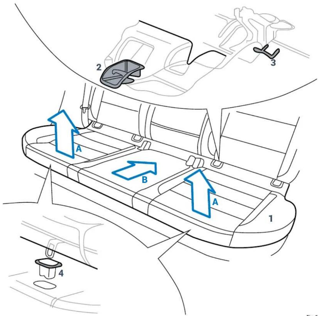
Fig. 3
6.2 Removing the right rear wheelhouse cover (5-door version)
6.2.1 Tip the right backrest forward to access the wheelhouse cover.
6.2.2 Remove the cap from the upper part of the covering (figure 4) with a plastic lever.
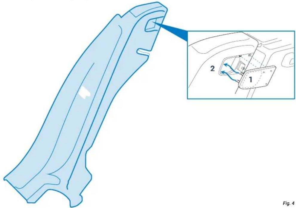
natural_image
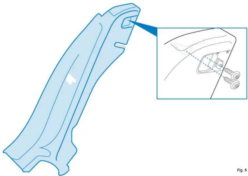
Technical illustration of a car body panel with an inset showing internal components (no text or symbols)6.2.3 Remove the two screws (Fig. 5).
natural_image
Technical illustration of a car body panel with an inset showing the internal components (no text or symbols present)6.2.4 Partially remove the gasket from the right door until the wheelhouse covering is free.
6.2.5 Remove nut 1 from bolt 2 (Fig 6).
6.2.6 Remove the covering from the body (Fig. 6 point 3).
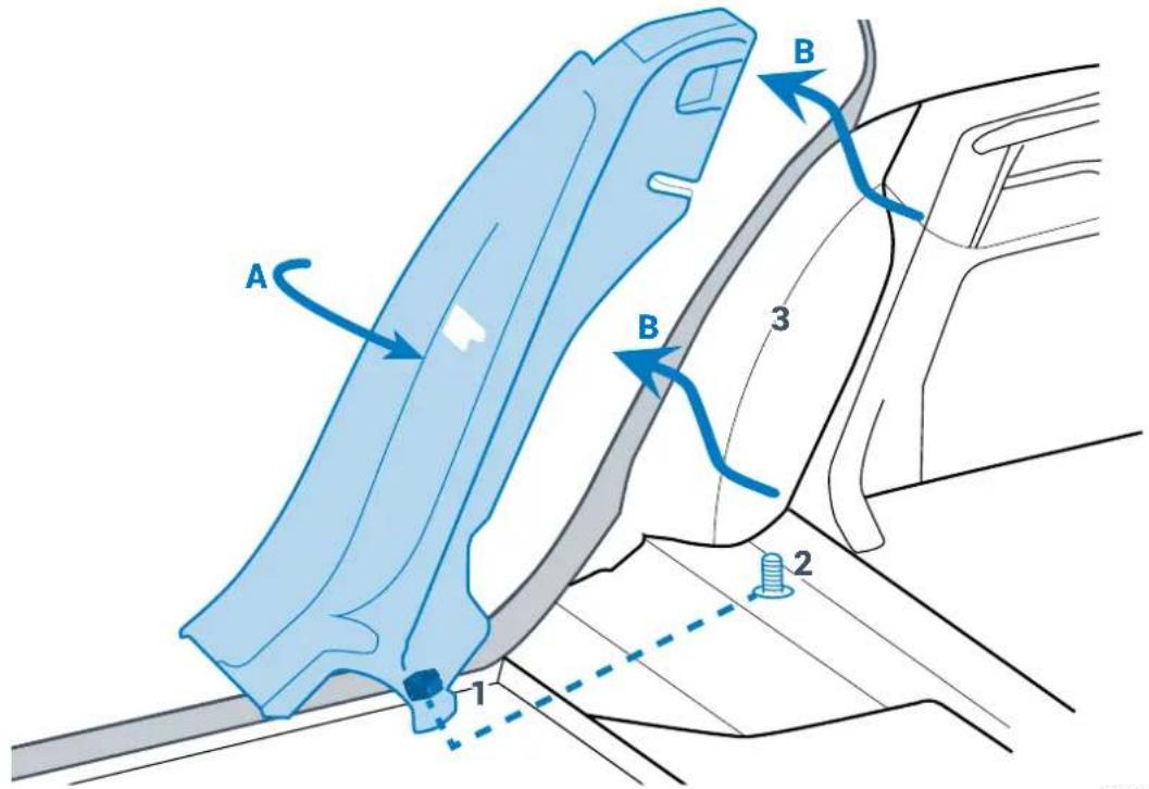
Fig. 6
6.3 Remove the right wheelhouse completely (Fig. 7)
6.3.1 Lift the front part of the door sill and release the fastening clip.
6.3.2 Release the guide from the lower part of the covering of the central pillar (Fig. 7 point 1).
6.3.3 Lift the rear part of the door sill and release the fastening clip.
6.3.4 Release the guide from the lower part of the covering (Fig. 7 point 3).
6.3.5 Release the tab and extract the safety belt (Fig. 7 point 2).
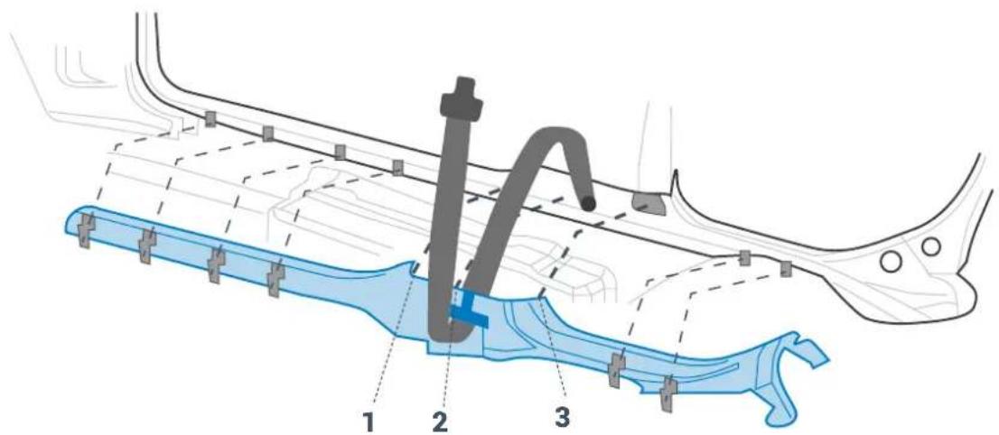
Fig. 7
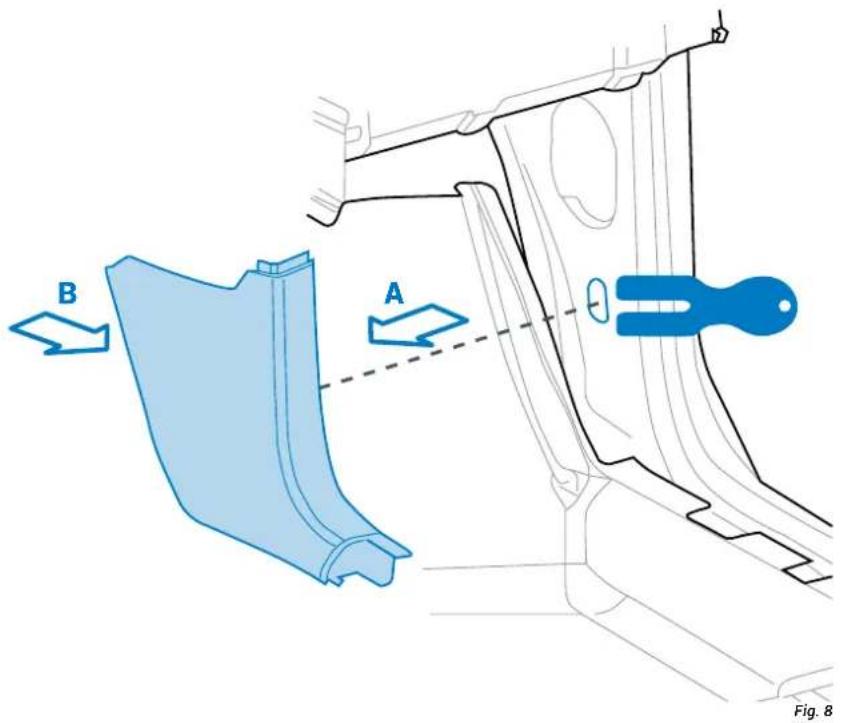
6.4 Removing the lower cover from the right pillar (Fig. 8).
6.4.1 Remove the covering with a lever and extract it, as shown by arrows A and B.
6.2.4 Partially remove the gasket from the right door until the wheelhouse covering is free.
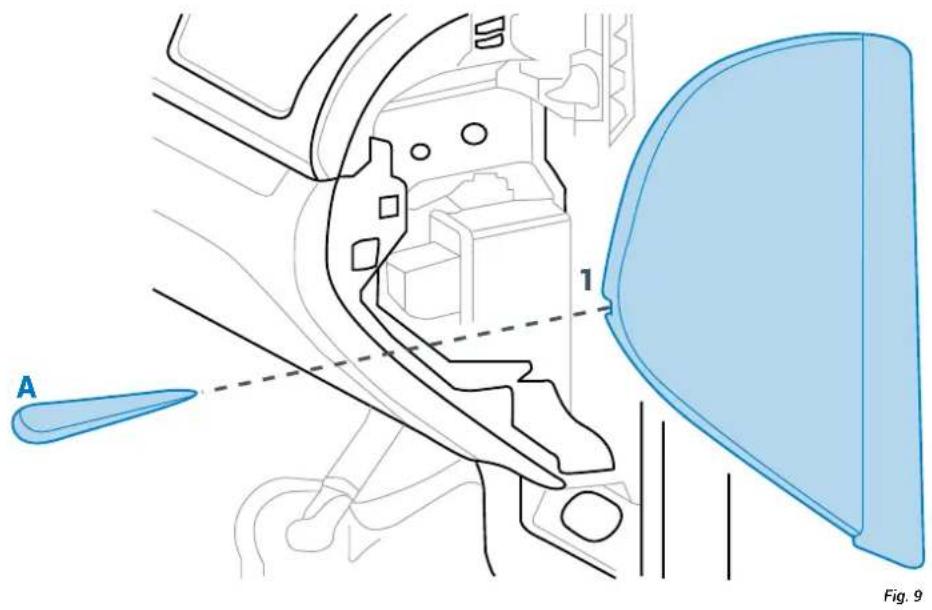
6.5 Removing the right side covering of the dashboard (Fig. 9).
6.5.1 Insert a plastic lever (A) into reference catch 1 and gently force it to the right to release the fastening clip.
7. REMOVING THE FRONT DOOR COVERING
WARNING: The procedure shown below describes the right side of the vehicle. Proceed in a similar manner

7.1 Removing the front door panel
7.1.1 Remove the door covering grille using a plastic lever, then loosen screws 1, 2, 3 and 4 (Fig. 10)
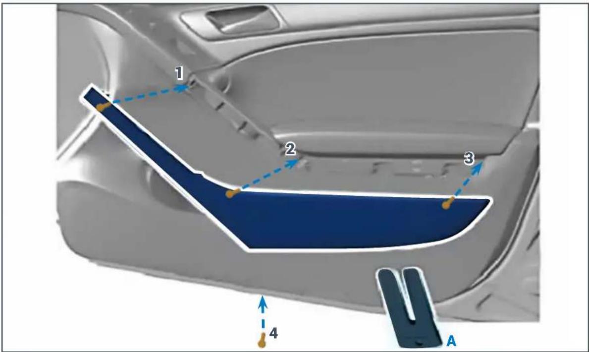
Fig. 10
7.1.2 Using a plastic lever, release all the covering clips according to the sequence shown (Fig. 11).
7.1.3 Lift the covering by firmly pulling upwards, as shown by arrow C in order to release it (Fig. 11).
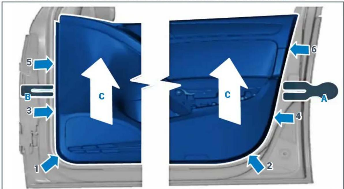
Fig. 11
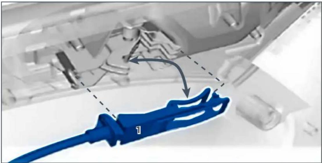
7.1.4 Release the door opening control cable (Fig. 12 point 1).
7.1.5 Disconnect all cables from the door's covering.
natural_image
Close-up of a blue cable with arrow indicating a component, no visible text or symbolsFig. 12
7.2 Removing the tweeter casing
7.2.1 Release the tweeter support from the three fastening caps using a plastic lever (Fig. 13 points 1, 2 and 3).
7.2.2 Disconnect the connector (Fig. 13 points 4).
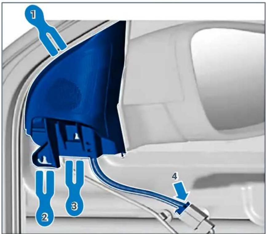
Fig. 13
8. PASSING THE APSP G6 HARNESS CABLE
WARNING: The procedure shown below describes the right side of the vehicle. Proceed in a similar manner

8.1 Passing the cable from the car radio's casing to the right of the dashboard
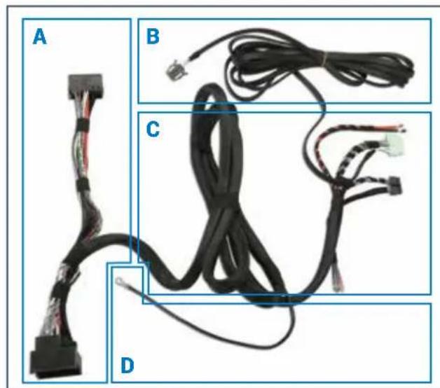
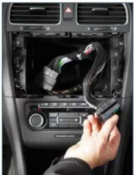
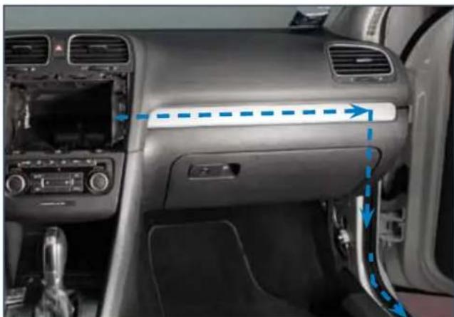
8.1.1 Pass sections B, C, and D of cable APSP G6 HARNESS (Fig. 14) from the car radio (Fig. 15) compartment above the glove compartment using a probe (Fig. 16 A).
APSP G6 HARNESS
natural_image
Close-up of four labeled cable assemblies (A, B, C, D) showing black and red wires with connectors and connectors, no text or symbols present.Fig. 14
natural_image
Person inserting a cable into a car's air vent, showing internal wiring and control panel (no visible text or symbols)Fig. 15
8.1.2 Insert the cable towards the door sill and connect earth cable D into bolt E (Fig. 16 B).
natural_image
Interior view of a car dashboard and infotainment system (no visible text or symbols)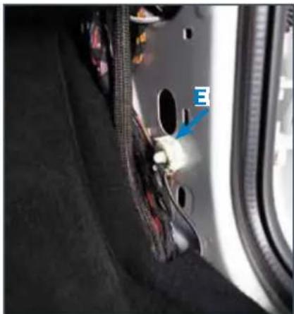
natural_image
Close-up of a car's side panel showing internal components and a blue arrow pointing to a component labeled 'E' (no readable text or symbols beyond the label)Fig. 16 A
Fig. 16 B
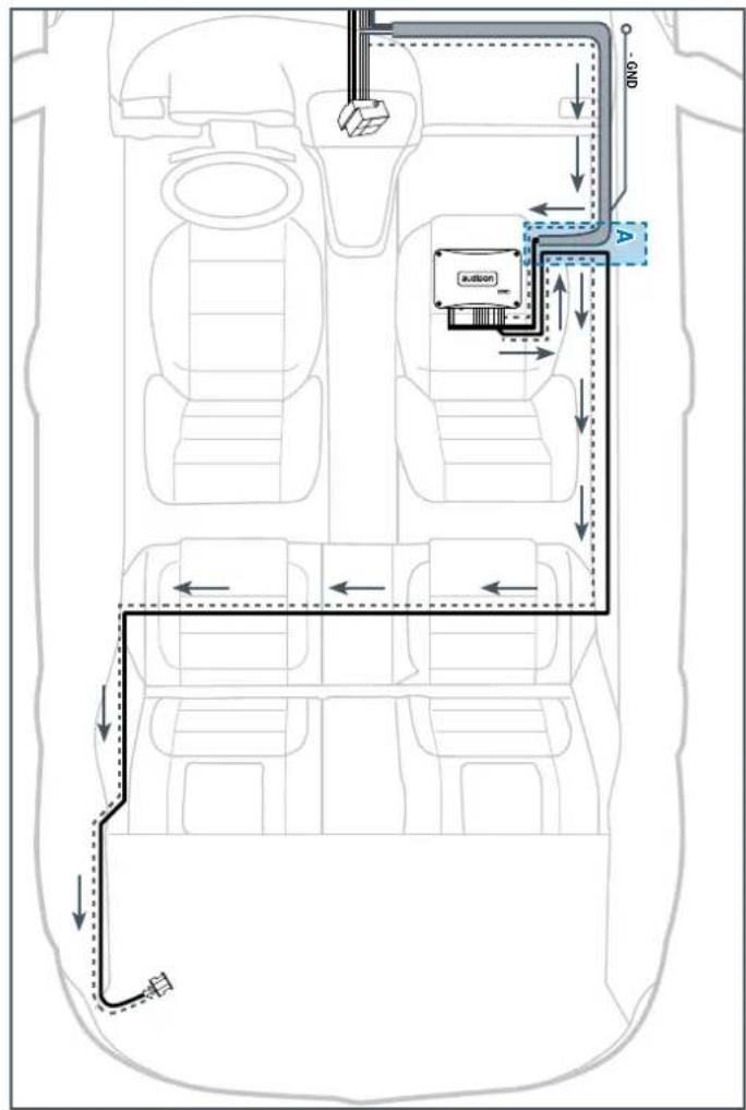
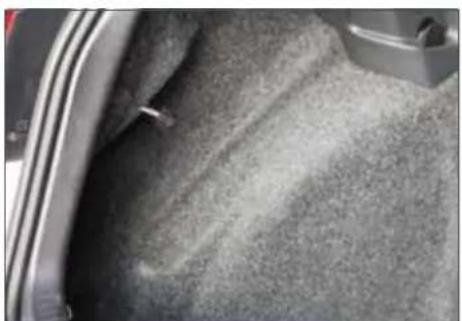
8.1.3 Lift the carpet from the floor in point A (Fig. 17) and insert cables C (Fig. 14) under the covering along the slits provided in the carpet. Make sure that both the connectors and power supply cables exit from the provided slots situated under the front right seat.
natural_image
Interior view of a car showing a car seatbelt and side panel with blue arrows indicating movement or force (no text or symbols visible)Fig. 18
natural_image
Close-up of a car's side panel with blue arrows pointing to specific areas (no text or symbols visible)Fig. 19
natural_image
Interior view of a car showing textured floor and side panel (no visible text or symbols)Fig. 17 Fig. 20
8.2 Passing the subwoofer power cable up to the left rear side of the boot
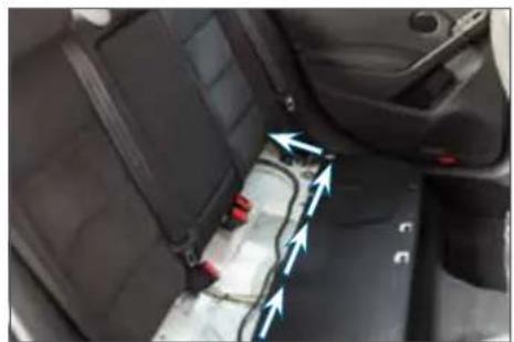
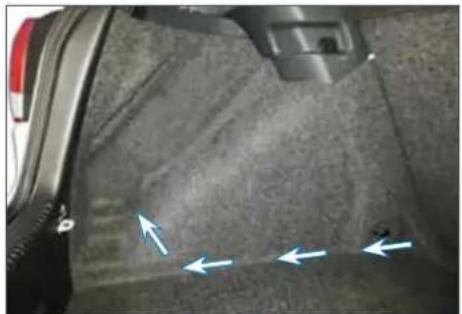
8.2.1 Insert the subwoofer's power cable B (Fig. 14) through passage A (Fig. 17), and run it along the door sill and through the rear bench seat and proceed until the left wall of the boot (fig. 18-19); the cable must exit from the provided slot (fig. 20).
9. APBX G6 SUBWOOFER INSTALLATION
9.1 Installing the mounting kit
9.1.1 Assemble the three brackets of the APBX G6 MOUNTING KIT onto the points provided on the box, strictly following the instructions reported in the figure (Fig. 21).
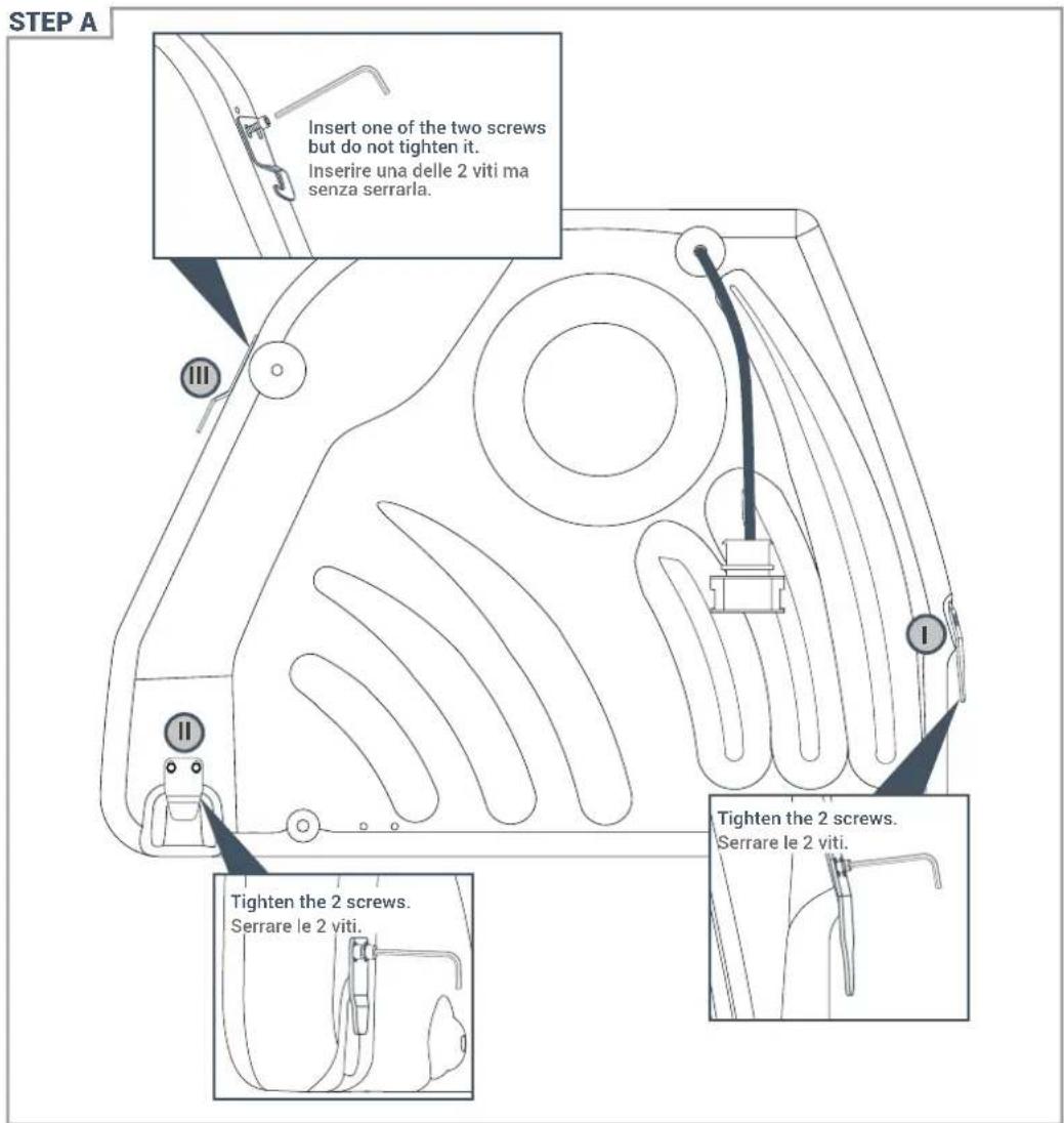
Fig. 21
9.2 Installing APBX G6 in the car
9.2.1 After positioning the DAMPING PANEL (Fig. 22 point 1), connect connector (Fig. 22 point 2) and insert brackets I and II of the box into the anchoring hooks of the boot (Fig. 22 points 3 and 4).
9.2.2 Place the box vertically (Fig. 22 point 5), rotate bracket and insert it into the anchoring hook of the backrest. Then also assemble the second screw and lastly tighten both in order to secure APBX G6 (Fig. 22 point 6 A/B).
STEP B: from 1 to 6

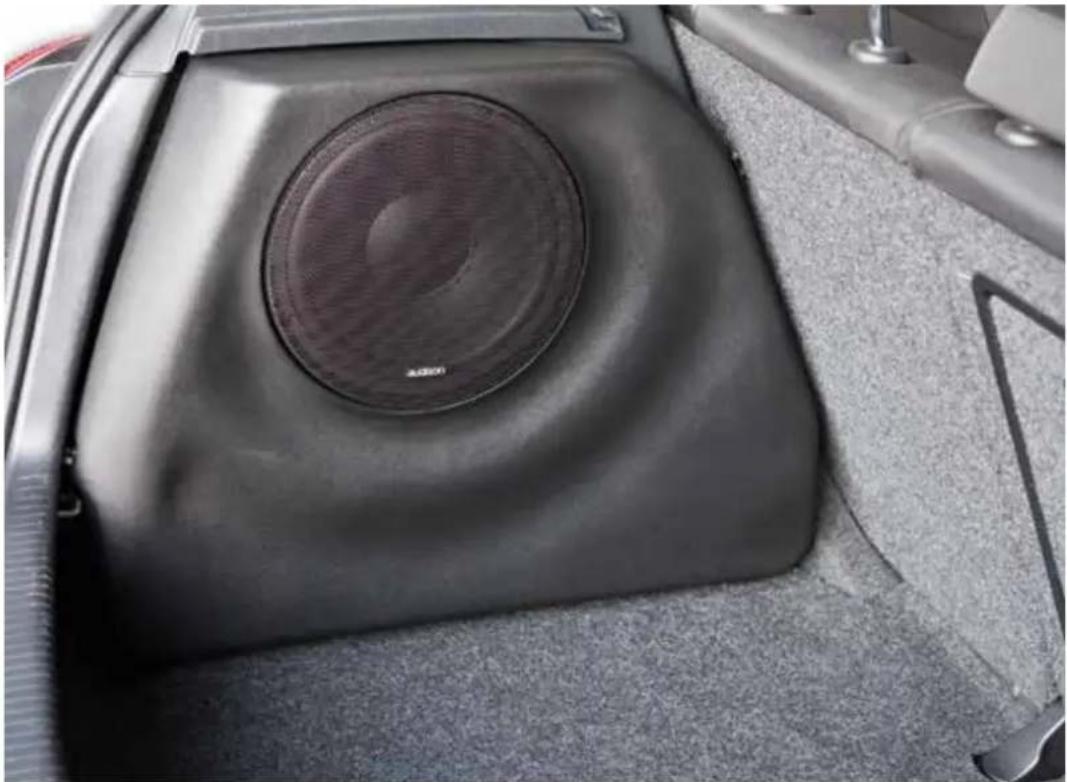
9.3 APBX G6 installation completed
natural_image
Interior view of a car's rear seat with a speaker grille and textured floor (no visible text or symbols)Fig. 23
10. AP 6.5 G6 WOOFER INSTALLATION
10.1 Removing original woofers
10.1.1 Disconnect the connector from the original woofer (Fig. 24 point 1).
10.1.2 Remove the 4 rivets that secure the woofer (Fig. 24 point 2).
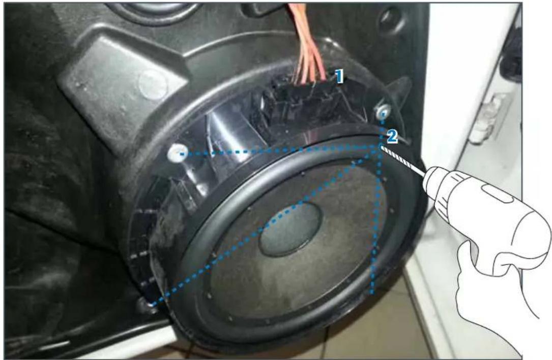
Fig. 24
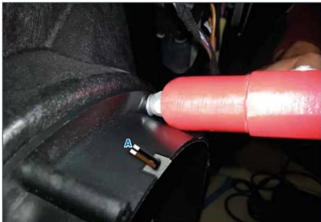
10.1.3 Place the AP6.5 RING in the points provided, making sure to position the cable gland slot upwards (Fig. 25 point A) and fasten it using the new rivets supplied in the KIT.
natural_image
Close-up of a red cylindrical device mounted on a black mechanical component, with a labeled point A pointing to it (no text or symbols beyond label)Fig. 25
10.2 APSP G6 SPEAKER CABLE connection to woofer AP6.5 G6
10.2.1 Insert the terminals, complying with the polarity (Fig. 26 point A).
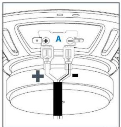
Fig. 26
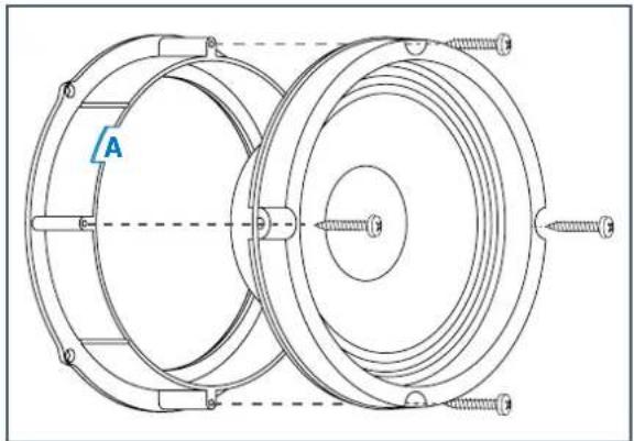
10.3 Assembling the woofer into the casing
10.3.1 Pass the power supply cable through slot A (Fig. 27) and fasten the speaker using the screws supplied with the KIT.
natural_image
Technical line drawing of a mechanical component with concentric rings and mounting holes (no text or symbols)Fig. 27
10.3.2 Connect the SPEAKER CABLE to the vehicle's default connector (Fig. 28 point A) positioning the crossover as shown in the photo (Fig. 28 point B).

natural_image
Pure electrical connector diagram without any text, numbers, or symbols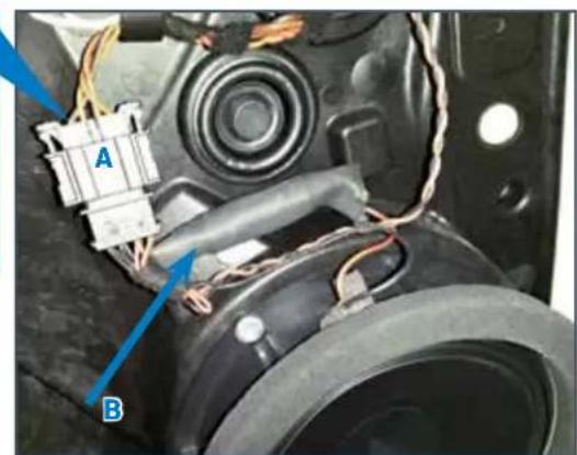
natural_image
Close-up of a mechanical component with wiring and labeled parts (A and B), no readable text or symbols beyond labelsFig. 28
11. AP 1 SP TWEETER INSTALLATION
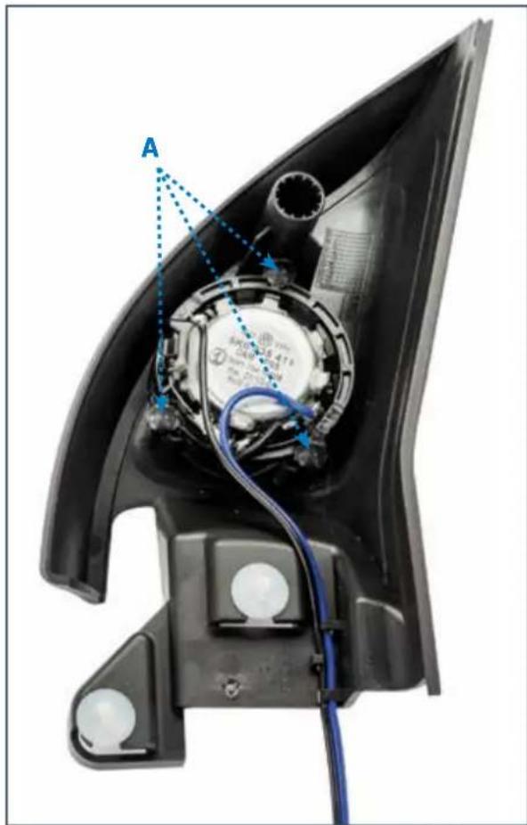
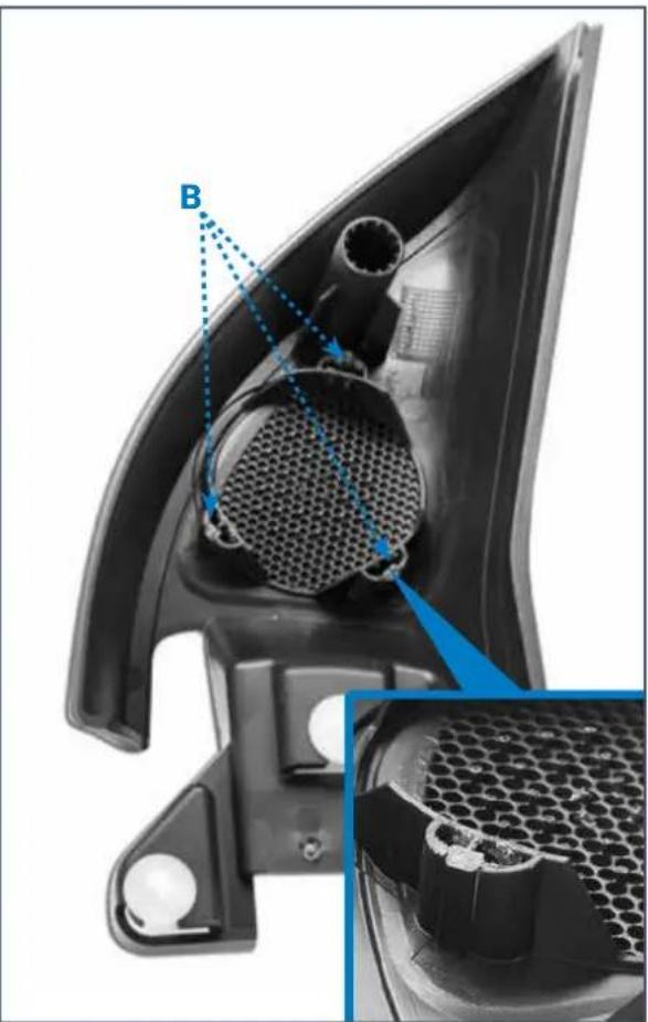
11.1 Removing the original tweeters from the casing
11.1.1 Removing the three plastic seals to release the tweeter (Fig. 29 points A).
11.1.2 Remove the three plastic pins from the point shown in the figure. (Fig. 29 point B).
natural_image
Close-up of a car head panel showing internal mesh structure and a close-up of the mesh detail (no text or symbols visible)Fig. 29
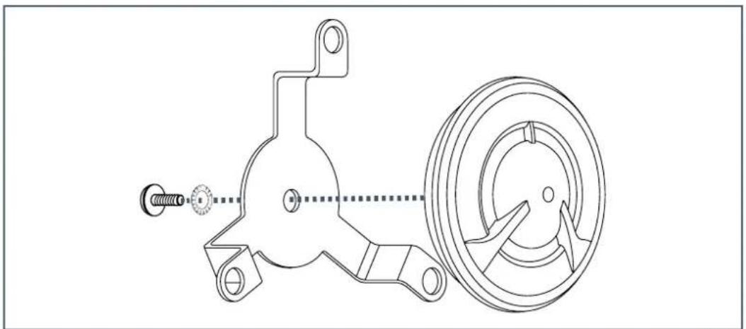
11.2 Installing the AP 1 SP MOUNTING KIT
11.2.1 Fasten the M3x5 mm screw as shown in the drawing (Fig. 30).
natural_image
Technical line drawing of a mechanical assembly with spring, nut, and wheel components (no text or symbols)Fig. 30
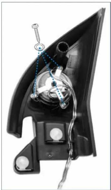
11.3 Installing AP 1 SP in the casing
11.3.1 Fasten the tweeter with the 3 self-tapping screws 3.5x10 mm supplied with the AP 1 SP MOUNTING KIT (Fig. 31).
natural_image
Close-up of a car headgear component with visible wiring and screwdriver (no text or symbols)Fig. 31
11.3.2 Reassemble the tweeter casing onto the door and connect the AP 1 SP cable to the SPEAKER CABLE.
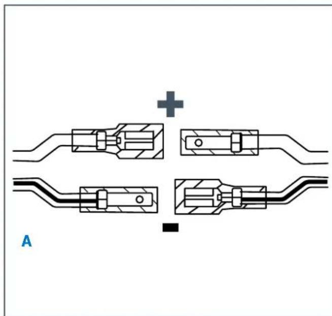
11.3.3 Comply with the cable's polarity (Fig. 32 point A).
11.3.4 Position the crossover as shown in the photo (Fig. 32 point B).
natural_image
Pure mechanical assembly diagram showing four connected components with no text or symbols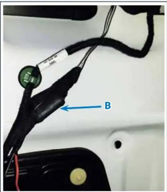
Fig. 32
12. AP8.9 BIT G6 INSTALLATION
12.1 Install ASP (Automatic Speaker Presence)
12.1.1 Install the ASP module in the provided place (Fig. 33).
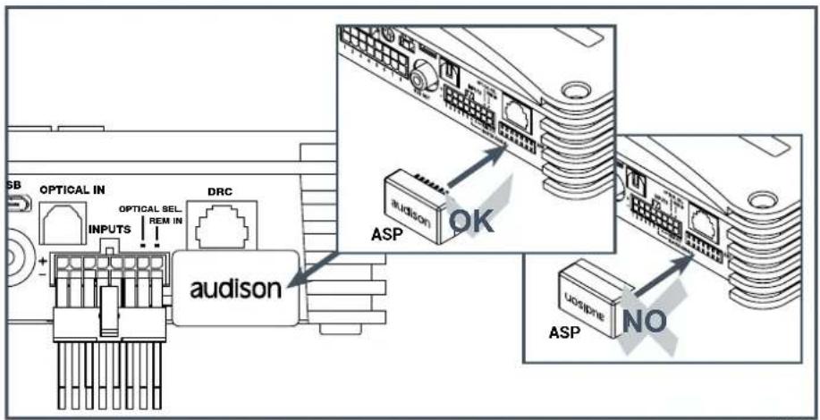
Fig. 33
12.2 APSP G6 HARNESS cable connection to AP8.9 bit G6
12.2.1 In sequence, connect:
A. Earth cable (black).
B. Power supply cable (red).
C. Outputs connector.
D. Inputs connector.
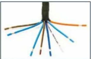
12.2.2 Isolate the cables from services that are not used (Fig. 35).
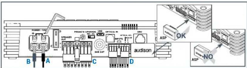
Fig. 34
natural_image
Close-up of bundled wires with orange and blue connectors (no text or symbols visible)Fig. 35
12.3 Positioning AP8.9 bit G6
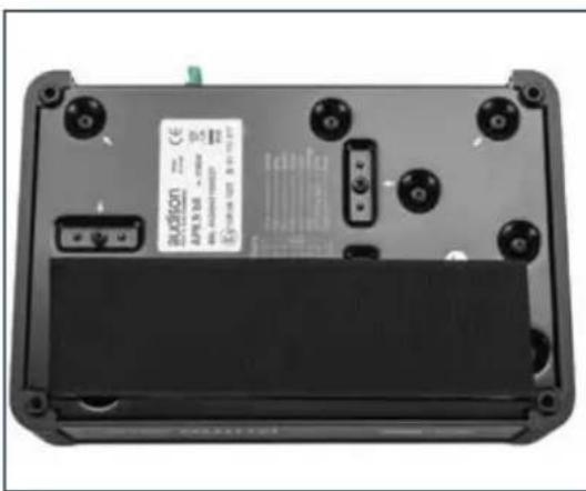
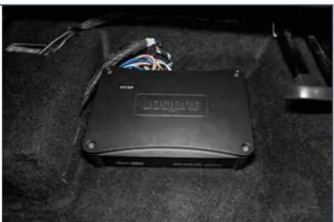
12.3.1 Position AP8.9 bit under the right seat, fastening it with the VELCRO tape supplied (Fig. 36).
natural_image
Black electronic device with visible wiring and a 'HOLDEN' logo on its body, placed on dark carpet (no readable text beyond branding)Fig. 36
13. CONNECTION OF THE APSP G6 HARNESS CABLE TO THE ORIGINAL CAR RADIO
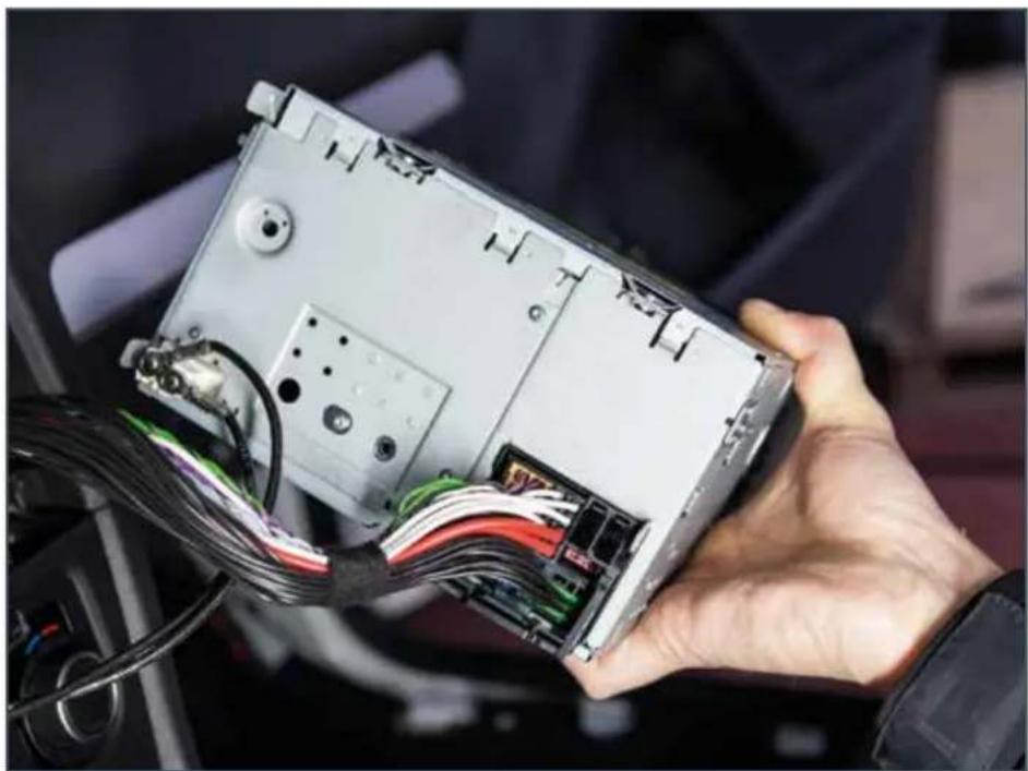
13.1 Connect the APSP G6 HARNESS cable, as shown in the figure (Fig. 37)
natural_image
Hand holding an open computer drive with visible wiring and components (no text or symbols)Fig. 37
14. REASSEMBLING ALL PARTS
14.1 Reassemble all parts of the vehicle by following the operations described in the disassembling sections.
WARNING: Be careful of the overall dimensions and fastening of new cables installed.

15. OPTIONAL ACCESSORIES
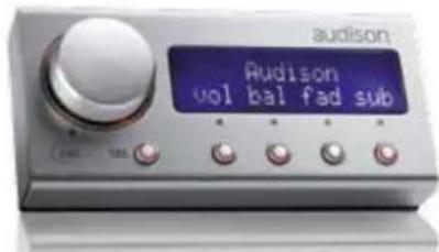
15.1 DRC DIGITAL REMOTE CONTROL
DRC is a digital interface between the bit processors and the user. A DRC assembled on the dashboard of the vehicle with AP bit processor, provides:
- The option to select between the main and aux inputs
- Control the general volume, subwoofer volume, balance and fader
- The option to select between 2 memory prsets defined by the user for equalizer and crossover alignment settings.
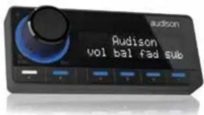
15.2 DRC-MP DIGITAL REMOTE CONTROL
The new Audison DRC MP (Digital Remote Control Multimedia Play) is compatible with all Audison electronics equipped with an AC Link bus. Its slim profile combined with the supplied holder makes it easier to install it in the best position of your car. The new Joystick, "Rubber Touch" finish for maximum movement control in the four direction axis enables "DRC Settings" menu adjustment and "Navi Command" navigation if equipped with an Audison bit Play HD with video output connected to a monitor. The matt black finish and the option to select amongst forty-two different colours of the keyboard enables easy integration of DRC MP with the car's dashboard. The new display with white characters is equipped with a sensor that automatically adjusts the brightness of the characters according to the light in the driver and passenger compartment, and is legible from any angle of vision.
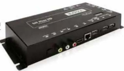
15.3 Bit Play HD
HD bit play and Play HD SSD bit are high-resolution multimedia servers specifically developed for car audio systems. Connecting the optical output of Play HD bit to an Audison processor or amplifier with digital input creates a Full DA system able to obtain new quality reference that goes beyond CD standards as a result of the possibility of reproducing FLAC audio files that are coded up to 24 bit/96 kHz.
To enable users who do not want to manage external hard drives, Play HD SSD bit is equipped with an internal SSD 2.5" unit of 240 GB, which is insensitive to vibrations and jolts that occur whilst driving, thanks to solid state technology and a mechanical casing with specifically designed damping. SSD is also much faster than a traditional hard disk and offers maximum speed to access multimedia content. If provided with video input, it is possible to connect the Play HD bit and Play HD SSD bit to the source or an external monitor via HDMI or compound video output and view the native interface of the multimedia server to control navigation functions and multimedia files directly through the remote control and access the device's configuration. Audison R&D department has designed an App for Apple and Android devices that enables you to connect the smartphone to Play HD bit and Play HD SSD bit via Wi-Fi and use it as a remote control manager of the multimedia catalogue without having to connect the reader to an external monitor.
natural_image
Exterior view of a black USB drive module (no visible text or symbols on body)15.4 OP 1.5 TOSLINK OPTICAL CABLE 1.5 m / 59.05 in.
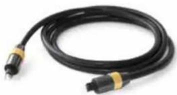
TOSLINK optical cable with terminations for S/PDIF digital audio signals.
Cable length: 1.5 m / 59.05 in.
15.5 OP 4.5 TOSLINK OPTICAL CABLE 4.5 m / 177.16 in.
TOSLINK optical cable with terminations for S/PDIF digital audio signals.
Cable length: 4.5 m / 177.16 in.
15.6 STA - F/F SOCKET TOSLINK ADAPTER
Optical adapter for TOSLINK optical cable extensions with terminations.
natural_image
Coiled black cable with metallic connectors, no visible text or symbols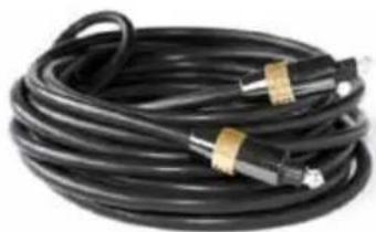
natural_image
Coiled black cable with connectors and tape, no visible text or symbols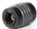
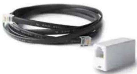
15.7 ECK DRC
DRC cable extension kit for installation on especially long vehicles. The total length of the cable supplied by default together with the extension is 6.5 m.
For all models
natural_image
Coiled black Ethernet cable and white connector (no text or symbols visible)16. TROUBLESHOOTING
| FREQUENTLY ASKED QUESTIONS | ||
| The car radio starts by no sound is heard | The AP8.9 bit G6 logo is off. | Check the power supply fuse. If necessary, replace it with a new one of the same type and value. Check for the presence of 12V on the power supply terminals. Make sure connector C chap. 12 has been inserted correctly (Fig. 34) |
| The AP8.9 bit G6 logo flashes blue, blue/red, red. | The “Logo Status” indicates the operation status of the product and any malfunctions. Refer to the operating manual of AP8.9 bit, sec. 4.12 or sec. 4.13. The user manual is loaded into the CD-ROM included in the box. It’s also available form www.audison.eu web site. | |
| The AP8.9 bit G6 logo is on correctly. The volume is too low. | ||
| The sound is not natural and does not come from all speakers | Incorrect setting of volume/balancer/fader controls. | Adjust the default source controls. |
| The connections are correct but are not secured. | Check the connections and secure them. | |
www.audison.eu

- Introduction
- Warranty
- Safe sound
- PRODUCT DESCRIPTION
- CONTENTS OF THE PACKAGE
- TECHNICAL SPECIFICATIONS
- Notes:
- CONNECTIONS LAYOUT
- REMOVING THE ORIGINAL CAR RADIO
- Extraction of the original car radio
- REMOVING THE DOOR SILL AND COVERINGS FROM THE RIGHT SIDE
- Removing the rear seat (Fig. 3 point 1)
- Removing the right rear wheelhouse cover (5-door version)
- Remove the right wheelhouse completely (Fig. 7)
- Removing the lower cover from the right pillar (Fig. 8).
- Removing the right side covering of the dashboard (Fig. 9).
- REMOVING THE FRONT DOOR COVERING
- Removing the front door panel
- Removing the tweeter casing
- PASSING THE APSP G6 HARNESS CABLE
- Passing the cable from the car radio's casing to the right of the dashboard
- Passing the subwoofer power cable up to the left rear side of the boot
- APBX G6 SUBWOOFER INSTALLATION
- Installing the mounting kit
- Installing APBX G6 in the car
- STEP B: from 1 to 6
- APBX G6 installation completed
- AP 6.5 G6 WOOFER INSTALLATION
- Removing original woofers
- APSP G6 SPEAKER CABLE connection to woofer AP6.5 G6
- Assembling the woofer into the casing
- AP 1 SP TWEETER INSTALLATION
- Removing the original tweeters from the casing
- Installing the AP 1 SP MOUNTING KIT
- Installing AP 1 SP in the casing
- AP8.9 BIT G6 INSTALLATION
- Install ASP (Automatic Speaker Presence)
- APSP G6 HARNESS cable connection to AP8.9 bit G6
- Positioning AP8.9 bit G6
- CONNECTION OF THE APSP G6 HARNESS CABLE TO THE ORIGINAL CAR RADIO
- REASSEMBLING ALL PARTS
- OPTIONAL ACCESSORIES
- DRC DIGITAL REMOTE CONTROL
- DRC-MP DIGITAL REMOTE CONTROL
- Bit Play HD
- OP 1.5 TOSLINK OPTICAL CABLE 1.5 m / 59.05 in.
- OP 4.5 TOSLINK OPTICAL CABLE 4.5 m / 177.16 in.
- STA - F/F SOCKET TOSLINK ADAPTER
- ECK DRC
- TROUBLESHOOTING
Brand : AUDISON
Model : Prima APSP G6
Category : Audio Amplifier