
RF60x - Flash Cactus - Free user manual and instructions
Find the device manual for free RF60x Cactus in PDF.


| Product Type | Wireless Flash |
| Brand | Cactus |
| Model | RF60X |
| Guide Number (ISO 100, 105mm) | 56 m (183 ft) |
| Zoom Range | 24, 28, 35, 50, 70, 80, 105 mm (motorized) |
| Power Levels | 22 levels: 1/1 to 1/128 with 1/3 and 2/3 stop increments |
| Flash Duration (t.5) | 1/1000 - 1/45000 sec |
| Operating Modes | Local, Master, Slave |
| Wireless Radio Frequency | 2.4 GHz |
| Channels / Groups | 16 channels / 4 groups (A, B, C, D) |
| Wireless Range | 100 m (328 ft) |
| Optical Slave | S1 (first flash) and S2 (main flash) with delay timer |
| AF-Assist Light | 1W LED, adjustable power (0-9) |
| Power Source | 4 x AA batteries (alkaline or Ni-MH) |
| Recycle Time (full power) | 1.9 sec (Ni-MH), 2.5 sec (alkaline) |
| Flash Count (full power) | 170 (Ni-MH), 110 (alkaline) |
| Color Temperature | 5600K ±200K |
| Dimensions | 205 x 83 x 61 mm |
| Net Weight | 395 g |
| Operating Temperature | -20°C to +50°C |
| Special Features | Cooling mode, Multi flash (up to 99 flashes), HSS (auto/manual), Group Aliases, Delay timer, Sleep timer, Quick flash, Beep feedback, LCD backlight, USB firmware update, External battery pack option |
Frequently Asked Questions - RF60x Cactus
User questions about RF60x Cactus
0 question about this device. Answer the ones you know or ask your own.
Ask a new question about this device
Download the instructions for your Flash in PDF format for free! Find your manual RF60x - Cactus and take your electronic device back in hand. On this page are published all the documents necessary for the use of your device. RF60x by Cactus.
USER MANUAL RF60x Cactus
- Getting to Know your RF60X 03
- Caution and Warnings 04
- Major Specifications 05
- Package Contents 06
- Nomenclature 07
- LCD Panel 08
- Getting Started 08
- On-camera Operation: 19 Local Mode
- Wireless Flash: 21 Master and Slave Modes
- Group Aliases 26
- Advanced Operation 28
- Personalizing the RF60X 44
- Working with Cactus 50 Triggers
- External Power 53
- Forming the Capacitor 54
- USB Connection 54
- Optional Accessories 55
- Troubleshooting 55
- Notices 59
- Warranty 62
1. Getting to Know your RF60X
Thank you for purchasing the Cactus Wireless Flash RF60X. The RF60X is unique among other flashes available in the market. With a built-in transmitter and receiver, it not only receives wireless signals, but also functions as a commander to control other RF60X or RF60. The possibilities are endless!
This new RF60X features outstanding improvement from its predecessor:
- Exclusive! Cooling mode to prevent RF60X from overheat cut-off;
-Quick full-power recharge time at 1.9 ; - Auto-focus assist light in sync with other Cactus devices;
- Automatic wireless HSS support in Slave mode for Canon, Fujif ilm, Nikon, Olympus, Panasonic, Pentax when working with V6 II; and Sony with V6 IIs transceiver.
Other features include:
-Built-in wireless commander and receiver
- Remote control of power and zoom levels
-Group control of up to four groups with configurable group Alias
- Optical slave with delay feature
- High power up to Guide Number of 56 meters
- Compatible with Cactus V6 IIs, V6 II and V6 Wireless Flash Transceivers - Multi-flash feature
2. Caution and Warnings
Before using the product, read the following instructions to ensure correct and safe use and to help prevent damage of the Cactus RF60X.
- Turn OFF all your equipment (Cactus units, cameras, etc.) before changing batteries or making a connection.
- Remove batteries and switch off the flash when it is not in
- Use only the batteries specified in this instruction manual.
- Do not permanently store the product in a high temperature environment (i.e., under strong direct sunlight, near cooking stoves or oven).
- The flash should not be in liquid or exposed to heavy rain unless it is properly protected.
- Do not operate the device in the presence of flammable gases or fu mes.
- Donot fire the flash dire into the eyes of someone at close range.
- Donot fire the flash dire the driver of a moving car.
3. Major Specifications
-Guide Number (ISO 100):
| Zoom (mm) | 24 | 28 | 35 | 50 | 70 | 80 | 105 |
| GN (m eter) | 33 | 34 | 38 | 45 | 51 | 54 | 56 |
| GN (fe et) | 108 | 112 | 124 | 147 | 168 | 177 | 183 |
-Motor zooms: 24 mm - 28 mm - 35 mm - 50 mm - 70 mm - 80 mm - 105 mm
-Power levels (22 in total):
| 1/1 | 1/2 | 1/4 | 1/8 | 1/16 | 1/32 | 1/64 | 1/128 |
| 1/2+0.3 | 1/4+0.3 | 1/8+0.3 | 1/16+0.3 | 1/32+0.3 | 1/64+0.3 | 1/128+0.3 | |
| 1/2+0.7 | 1/4+0.7 | 1/8+0.7 | 1/16+0.7 | 1/32+0.7 | 1/64+0.7 | 1/128+0.7 |
-Flash durations (t.5): 1/1,000 - 1/45,000 sec
- Modes: Local (L), Master (M), and Slave (S)
-Working radio frequency: 2.4 GHz
-Number of channels: 16
-Number of groups: 4
-Maximum wireless effective distance: 100 meters (328 feet)
-Built-in optical slave
-AF-assist light: 1W LED
- Power input: 4 AA-sized batteries
| Battery Type | Primary LR6 Alkaline 1.5V | Rechargeable HR6 Ni-MH 1.2V |
| Flash Count at Full Power | 110 | 170 |
| Recycle Time at Full Power | 2.5 sec | 1.9 sec |
-Color temperature at full power: 5600k +/- 200k
-Operating temperature:
$$ - 2 0 ^ {\circ} \mathrm{C} \text { to } + 5 0 ^ {\circ} \mathrm{C} $$
-Dimensions: 205 x 83 x 61 mm
-Net weight: 395 g
4. Package Contents
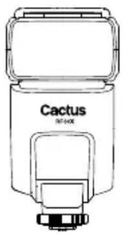
natural_image
Line drawing of a Cactus flash unit (no text or symbols on body)Flash RF60X
Carrying Case FC-3
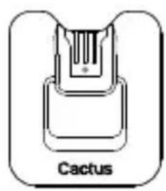
natural_image
Diagram of a cactus component with labeled parts (no text or symbols beyond label)Flash Stand FS-2
User Manual
5. Nomenclature
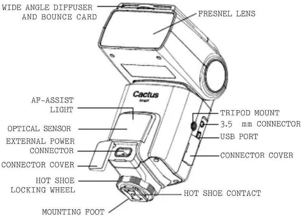
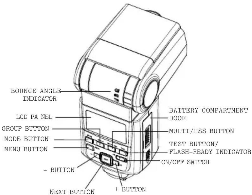
6. LCD Panel
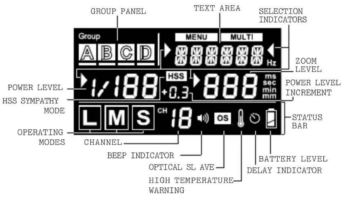
7. Getting Started
7.1 Inserting Batteries
natural_image
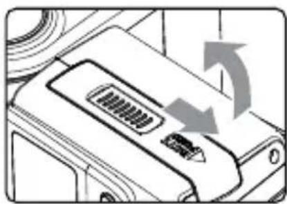
Diagram of a device's internal components with directional arrows indicating rotation or movement (no text or symbols)- Using your thumb, press on the battery compartment door and slide it open in the direction shown by the arrow.
natural_image
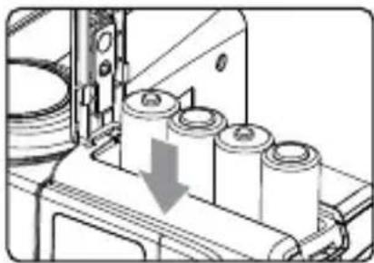
Mechanical assembly diagram showing cylindrical components and a downward arrow indicating motion (no text or symbols)- Install the batteries.
Make sure the positive (+) and negative (−) battery contacts are properly oriented as shown in the compartment.
natural_image
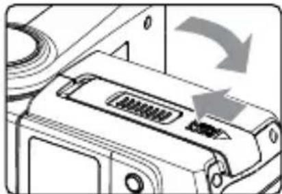
Diagram of a device's internal structure with a scroll arrow indicating rotation (no text or symbols present)- Slide the battery compartment door in the direction shown by the arrow to close it.
Caution:
-
Use a new set of AA batteries of the same brand and type. When replacing batteries, replace all four at the same time.
-
AA-sized alkaline, Ni-MH, or lithium batteries can be used. Use only one type of batteries at a time. Do not mix battery types.
-
If you change batteries after f iring many flashes continuously, be aware that the batteries may be h ot.
-
For alkaline or lithium batteries, the battery level indicator on the LCD will show

when around 50% of the battery power has been consumed, and
the indicator will blink when the flash does not
power to fire. Replace batteries immediately when you see the blinking signal. The indicator is not applicable to Ni-MH battery.
- When the flash is not in use, remove the batteries to prevent possible damage from battery corrosion.
7.2
Attaching the Flash to and detaching it from the Camera
natural_image
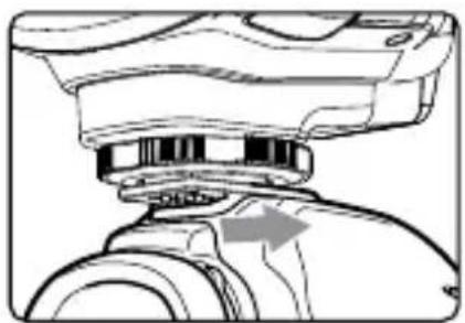
Technical line drawing of a mechanical assembly with a highlighted component (no text or symbols)- To attach the flash, slid flash's hot shoemounting fall the way into the came shoe.
natural_image
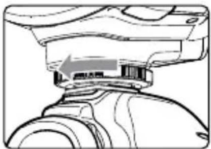
Technical line drawing of a mechanical component with a highlighted section (no text or symbols)- To secure the flash, rot a locking wheel on the mounting foot to the left until it locks.

natural_image
Technical line drawing of a mechanical component with an arrow indicating a process or assembly (no text or symbols present)- To detach the flash, rotate the locking wheel on the mounting foot to the right until it is loosened.
7.3
Turning the Flash On
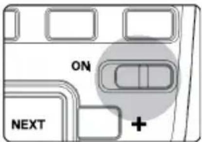
- Switch the On/Off Switch to ON.
The flash starts charging.
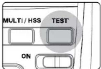
- Check that the flash is read
- The flash-ready indicator or in red, indicating that the fla is ready for quick flash (see Section 12.4).
- Once fully charged, the f ready indicator stays red and the flash is ready to give full output.
- Press the button to fire a test flash.
Caution:
- When the flash is switched 0 not used, after a certain period of time, the flash's power off automatically. However, the flash still consumes power batteries discharge over a long period of time, which may damage the battery contacts of the Therefore, shut off th
power if the flash
-
The overheating protection of the RF 60X may stop the flash firing after a number of full power flashes have been fired in short intervals. The temperature warning signal will appear in the status bar of the LCD display. If this occur, allow a rest time of about 15 minutes and the flash will then nor mal.
-
To prevent the flash from heating, turn on the Cooling Mode (see Section 12.1).
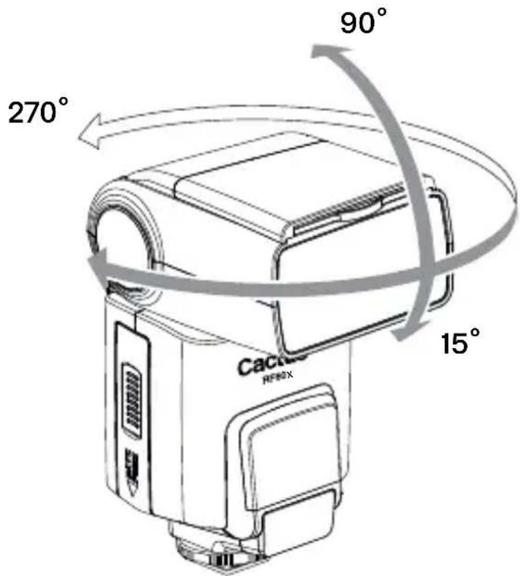
7.4 Adjusting the Flash Head
By pointing the flash toward ceiling, the flash will bounce off the surface before illuminating the subject. This will soften the shadows behind the subject for a more
natural-looking shot. This is called a bounce flash.
Tip: When using bounce flash avoid hitting the subject with direct flash light. Make su flash head is suff iciently angled away from the subject.
The flash head of the RF60 X tilted up to a vertical angle with click stops at 30^ , 60^ , 75^ , down at 15^ . Horizontally, it c rotated up to 180^ to the right 90^ to the left, with click stop 30^ , 60^ , 90^ , 120^ , 150^ (right) at 30^ , 60^ (left).
7.5
Bounce Card and Wide Angle Diffuser
There is a bounce card and wide angle diffuser set built in the RF60X. The bounce card and wide angle diffuser can be used separately or at the same time.
Tip: The bounce card is useful in bounce flash applications to direct some of the light toward the subject in order to create catch lights and/or soften strong shadows from the bounced light.
Using the Bounce Card
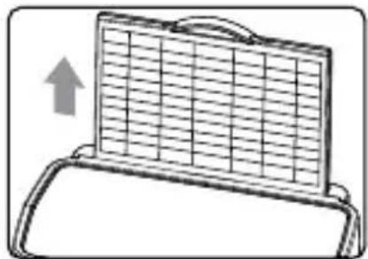
natural_image
Diagram of a folding table with a grid pattern and an upward arrow, no text or symbols present- Point the flash head up w a
- Pull out the wide angle diffuser. The bounce card will come out at the same time.
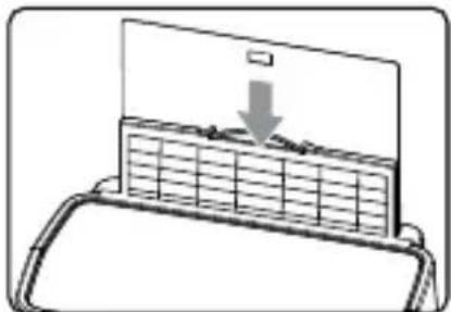
natural_image
Diagram of a printer or printer with a grid cover and a downward arrow indicating compression or disassembly (no text or symbols present)- Push the wide angle diffuser back in. The bounce card will be ready for use.
Using the Wide Angle Diffuser
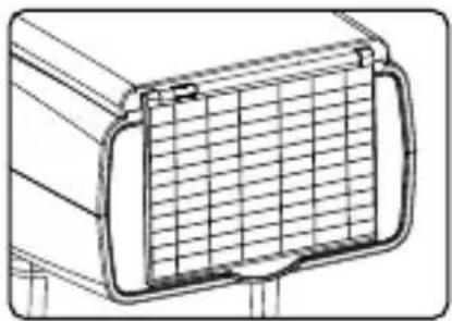
natural_image
Technical line drawing of a rectangular container with internal grid pattern (no text or symbols)-
Pull out the wide angle diffuser and place it over the flash head as shown. The bounce card will come out at the same time.
-
Push the bounce card back in. The flash will illuminate coverage.
7.6
Choosing the Operating Mode
There are three operating modes in the RF60X, namely Local, Master, and Slave. Upon switching on the RF60X, press the button to choose the appropriate mode. The mode indicator turns in the following sequence:

flowchart
graph LR
    Local --> L
    L --> Master
    Master --> M
    M --> Slave
    Slave --> S
| Modes | Where to place the RF60X? | With wireless control? | |
 | on camera X | ||
 | on camera √ | ||
 | off camera √ | ||
7.7 Setting the Channel and the Radio ID
When the RF60X units are in the Master or Slave mode, they need to communicate in the same RF wireless channel with each other.
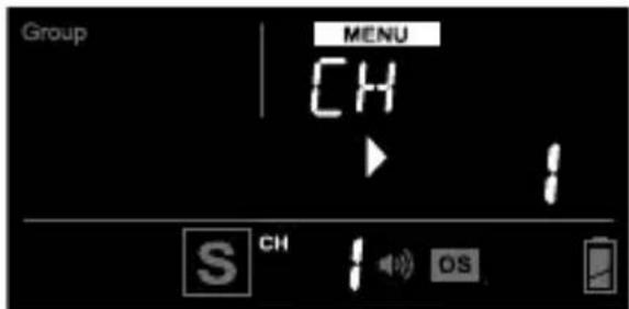
To set the channel, press MENen press the NButton until
To protect your setup from
interferences by other Cactus
devices, assign all your RF60X to a
specific radio ID. Press MENU, then
press the Next button until
7.8 Navigating the Menu MENU
There are a number of configurable menu options on the RF60X.
To change a menu option:
-
Press the MENU button to access the first menu item.
-
Press the NEXT ton to change the menu subject in the sequence.
-
Press the +or button to see each option of a menu item. The configuration of the menu item will change immediately.
-
Press the menu to leave and go back to the main screen, or press the next to change the menu to the next item in the sequence.
| Menu item and corresponding options | Text shown on LCD | Applicable modes | ||
| L | M | S | ||
| AF-assist Continuous ModeOffOn | AF CONOFFON | √ | √ | √ |
| AF-assist Power0-9 | AF PWR0-9 | √ | √ | √ |
| Optical SlaveOffS1: StraightTriggeringS2: Pre-flash | OPT SLOFFS1 (FIRST)I S2 n(MAIN)e d | √ | √ | √ |
| Delay Timer0-999 ms1-99 sec | DELAY0-999 ms1-99 sec | √ | √ | √ |
| Auto HSSOffOn | AU HSSOFFON | √ | ||
| Cooling ModeOffOn | COOLOFFON | √ | √ | √ |
| Quick FlashOffOn | QCK FLOFFON | √ | √ | √ |
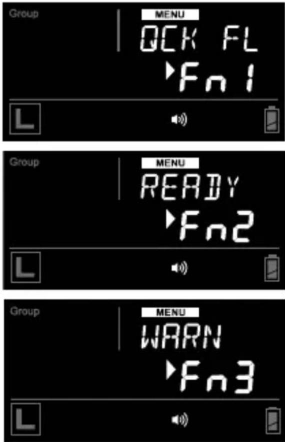
| Beep FeedbackOffFn1: Quick FlashFn2: Full ChargeFn3: Insuff icient Power Warning | BEEPOFFFn1 (QCK FL)Fn2 (READY)Fn3 (WARN) | √ | √ | √ |
| LCD Backlight15 sec1 min5 minContinuous | BK LGT15 sec1 min5 minON | √ | √ | √ |
| Sleep TimerOff3 min5 min15 min30 min60 min | SLEEPOFF3 min5 min15 min30 min60 min | √ | √ | √ |
| RF Channel1-16 | CH1-16 | √ | √ | |
| Radio ID0-999 | RAD ID0-999 | √ | √ | |
8. On-camera Operation: Local Mode L
Set up the RF60X in Local mode when you work with one flash camera'shot shoe.
In the main screen, the power level is shown on the left while the zoom level is shown on the right. The selection indicator ▶ will be shown at either the power level or zoom level. Press the NEXT button to switch the selection indicator in order to adjust a setting of an item.
8.1 Adjusting the Power Level
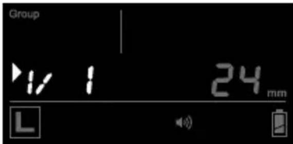
To adjust the power level, press ▶NEXT until the selection indicator ▶ is pointing to the power ratio value (i.e., the left figure in the center row). Press +to increase or ▶to decrease the power level.
The power levels available for adjustment are:
| 1/1 1/2 | 1/4 1/8 1/16 | 1/32 1/64 | 1/128 | ||||
| 1/2+0.3 | 1/4+0.3 | 1/8+0.3 | 1/16+0.3 | 1/32+0.3 | 1/64+0.3 | 1/128+0.3 | |
| 1/2+0.7 | 1/4+0.7 | 1/8+0.7 | 1/16+0.7 | 1/32+0.7 | 1/64+0.7 | 1/128+0.7 |
8.2 Adjusting the Zoom Level
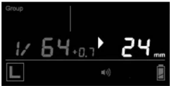
To adjust the zoom level, press NEXT until the selection indicator ▶ is pointing to the zoom value (i.e., the right figure in the center row). Press + to increase or - to decrease the zoom level.
The zoom levels available for adjustment are:
| Zoom (mm) | 24 | 28 | 35 | 50 | 70 | 80 | 105 |
9. Wireless Flash: Master and Slave Modes M S
With a built-in Radio Frequency (RF) module, the RF60X has the ability to communicate with other RF60/RF60X units wirelessly. To control and fire the RF60/RF60X wirelessly, set up one RF60X in Master mode and the other RF60/RF60X units in Slave mode.
9.1 Setting up the RF60X Slave
- Make sure that the RF60X units that you want to control through the Master flash mode set (see Section 7.6).
- Set the units to the same RF channel (see Section 7.7).
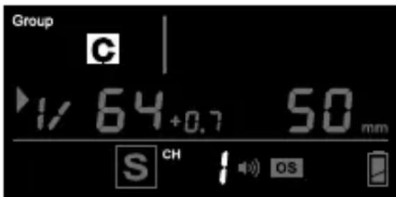
- Assign RF60X Slave units to either group A, B, C, or D. Press GROUP to select the group for each RF60X. Each press of the Group button in Slave mode will change the group in the sequence of A-B-C-D. The selected group will be shown on the group panel.
9.2 Commanding with the RF60X Master
-
Set the on-camera RF60X to mode by pressing MODE Section 7.6).
-
Set the RF60X Master to the same channel as the RF60X Slave units (see Section 7.7).
-
Check the group statuses on the group panel. Only activated group(s) will be shown as A, B, C, or D boxes.
Changing Parameters of the Master Flash
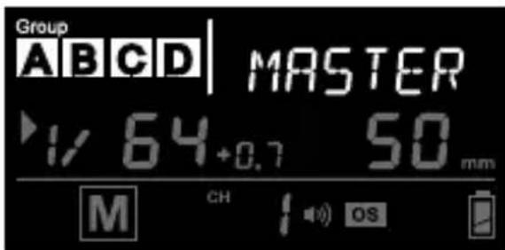
-
On the RF60X Master, you can change the power level and zoom level of the Master flash it and the RF 60X Slave flashes groups A, B, C, and D.
-
The default group is the Master RF60X. In the display, the text area will show
. No group is selected in the group panel, though it still shows the group activation status.
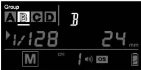
Changing Parameters of a particular Slave Group
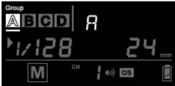
- To select a particular group for remote control press Group the group selection indicator will go to group A.
-
Press Group in to select the next group, i.e., group B. Each press of the Group button will select the next group in the following sequence: Master → A → B → C → D
-
Adjust the power level of the Master flash or of a particular group using the + or -button. Press Next adjust the zoom level. You can also adjust the zoom level with the or -button.
Note: The power and zoom level will only apply to the group being selected.
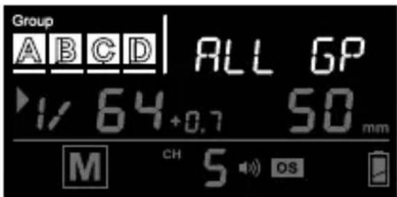
Changing Parameters of all Active Groups
-
You may also change settings for all active groups at the same time. To select all groups press and hold the button.
-
The selection indicators of all groups will be on and the text area will show
. The first activated group in the sequence of Master-A-B-C-D will be chosen as the reference group. -
Adjust the power and zoom levels as you would for a single group. The relative changes in both settings in the reference group, however, will apply to all active groups, including the Master flash. For example, by adjusting the power level of the reference group from 1/4 to 1/8 (i.e., a decrease of 1EV), the power levels of all the active groups will decrease by 1EV accordingly.
-
To exit from all group control, press the GROU on once.
Turning on and off a Slave Group
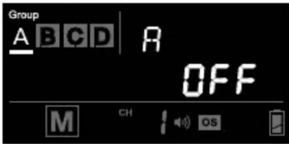
- If you wish to stop firing a particular group, turn the group off by selecting the group (see steps 6 and 7) and press and hold the button. The screen will show
in the center row.
Note: The RF60X Master can also be turned off by pressing and holding the button in the Master group. Once turned off, the RF60X Master will not fire, but it will still command the RF60X Slaves, changing their settings and firing them accordingly.
-
To turn on a group again, select the group (see steps 6 and 7) and press and hold the NEBOTTON. The power level and zoom level last used for the group will be shown in the center row again.
-
Press the shutter release button on the camera and the RF60X Master and Slave units in groups A, B, C, or D will fire at the power level and zoom level you have set in the RF60X Master.
10. Group Aliases
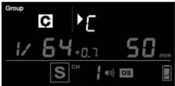
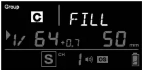
The RF60X comes with a list of pre-set group aliases to choose from for the particular slave groups according to the purpose of each. The chosen group alias will be shown in the text area next to the group panel. The group alias will display whenever the group is selected.
The group aliases available for selection are:
KEY - FILL - SPOT - RIM - HAIR - LEFT - RIGHT - BACK - FRONT
-
To set a group alias, select the group you would like to set an alias for, then press the GROUP and MButtons simultaneously.
-
The selection indicator and group letter will be shown in the text area. Press the +r button to scroll through the available group aliases.
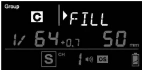
- Press on next menu
the alias and exit.
- Repeat steps 1-3 to set aliases in all the Cactus RF60X units. To prevent confusion, make sure that you have set the same alias for the same group in all RF60X units.
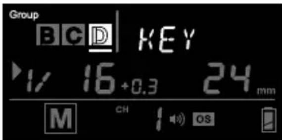
- The alias of each group will appear in Slave mode or Master mode whenever the group is selected.
11. Advanced Operation
11.1
Multi Flash
MULTI
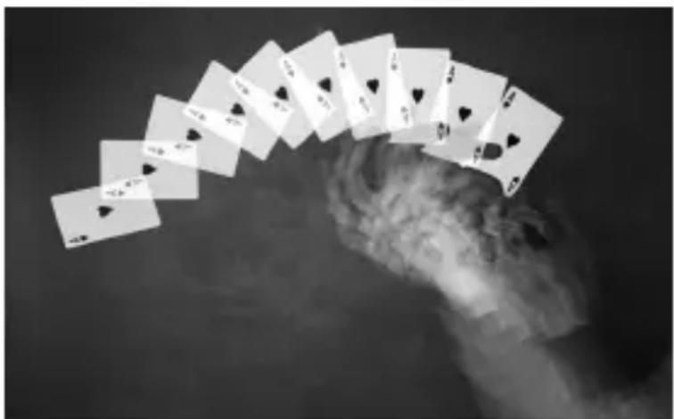
In Multi mode, a rapid series of flashes is fired. It can be used to capture multiple images of a moving subject in a single frame.
natural_image
Black and white photo of multiple playing cards floating in the sky with clouds below (no text or symbols visible)In Multi mode, you can change the:
• Number of flashes in a series
• Flash frequency per second in Hz
- Power level
- Zoom level
The number of flashes repr number of flashes firing in a series caused by a single trigger event.
The flash frequency the number of times t
per second. Together with the flash series duration you have in mind, you can determine the appropriate value for the number of flashes and frequency.
Flash series = No. of x 1 duration flash e Flash Frequency(Hz)
For example, if you wish to fire a series of flashes that lasts f 0.5 second at a frequency of 10 times per second (i.e., 10Hz), the number of flashes would be 5.
Similarly if you wish to fire 10 flashes at a frequency of the flash series would last 0.1 second.
The flash series duration is equal to the shutter speed. However, it may be necessary to use a longer shutter speed that exceeds the flash series duration in order to expose for ambient light. Alternatively, it may be necessary to use a shorter shutter speed, and a slightly longer series duration as a safety margin.
Refer to the table below for the maximum number of flashes a frequencies supported by each power level.
Maximum Number of Multi Flashes
| Power\Hz | 123456-78-9 | ||||||
| 1/4 | 7 | 6 | 5 | 4 | 4 | 3 | 3 |
| 1/8 | 14 | 14 | 12 | 10 | 8 | 6 | 5 |
| 1/16 | 30 | 30 | 30 | 20 | 20 | 20 | 10 |
| 1/32 | 60 | 60 | 60 | 50 | 50 | 40 | 30 |
| 1/64 | 90 | 90 | 90 | 80 | 80 | 70 | 60 |
| 1/128 | 99 | 99 | 99 | 99 | 99 | 90 | 80 |
| Power\Hz | 10 11 | 12-14 15- | 19 20-50 | 60-199 | ||
| 1/4 2 2 2 | 2 2 2 | |||||
| 1/8 4 4 4 | 4 4 4 | |||||
| 1/16 8 8 8 | 8 8 8 | |||||
| 1/32 | 20 | 20 | 20 | 18 | 16 | 12 |
| 1/64 | 50 | 40 | 40 | 35 | 30 | 20 |
| 1/128 | 70 | 70 | 60 | 50 | 40 | 40 |
Notes:
- Multi flash is most effective with a highly reflective subject against a dark background.
- Multi flash is not supported at power level higher than 1/4.
- The Multi flash may be useful when combined with a camera set to bulb mode.
11.1.1 Multi Flash in Local Mode
Once you have determined the number and the frequency of flashes in a series, you can set up the flash in Multi mode.
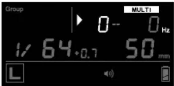
- To enter Multi Mode, press
MULTI / HSS once and the LCD display will show MULTI and Hz
-
Press NEXT until the selection indicator ▶ points to the number of flashes, i.e., the valueb the hyphen.
-
Press to increase or to decrease the number of fla
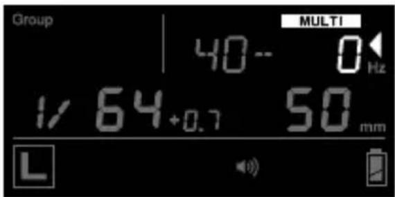
-
Pres next til the selection indicator ▶ points to the frequency of flashes (Hz), i the value after the hyphen.
-
Press to increase or to decrease the flash frequency second.
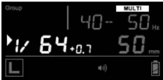
-
To adjust the power level, press NEXT until the selection indicator ▶ points to the power level (see Section 8.1).
-
To adjust the zoom level, press NEXT until the selection indicator ▶ points to the zoom level (see Section 8.2).
-
To exit Multi mode, press MULTI/HSS twice to return to the main screen.
11.1.2 Multi Flash in Master and Slave Modes
An RF60X in Master mode will cause a Slave RF60X that uses the same RF channel to synchronize to Multi mode settings.
- To enter Multi mode on the RF60X Master, pre GROUP until you see
displayed as the group name. - Press the button once. The LCD of the RF60X Master and Slave units will show MULTI Hz. Both Master and Slave units are now in Multi Flash mode.
- On the RF60X Master, follow the steps in 11.1.1 to adjust the number of flashes and flash frequency per second (Hz). The flash frequency will apply Master and Slave units in all active groups.
- To exit Multi mode, press MULTI/HSS twice to return to the main screen.
Notes:
-
When the number of flashes is larger than that supported by the power level of a particular slave group, it will be reduced accordingly for that particular slave (see table Maximum Number of Multi Flashes on page 29-30).
-
Since Multi mode flashes are not supported in power levels higher than 1/4, any Slave RF60X set at power levels higher than 1/4 will only flash once in Multi mode
-
Multi mode and HSS Sympathy mode (see Section 11.2) are mutually exclusive options. Pressing the MULTI/HSS button changes modes in the following sequence: Normal Flash → Multi Flash → HSS Sympathy Flash
-
On the RF60X Master, Multi mode flashes canonly be the Master group. The selection will apply to the RF60X Master and all RF60X Slaves in the active group(s).
the fl
11.2
HSS Flash HSS
The HSS flash of the RF60X is designed to support flash photographs shutter speeds beyond a ca maximum sync speed.
To this end, the RF60X will fire flashes with an extended disorder to produce even frame illumination at shutter speeds as high as 1/8000 second.
Tip:
HSS flash is commonly used outdoor, especially in sunlight. The faster shutter speed supported by HSS flash
allows you to use a wider aperture to achieve shallower depth of field while maintaining correct exposure.
11.2.1 Characteristics of HSS Flash
Compared with normal single-burst flash, the HSS flash provides continuous and constant illumination for the full duration between the first curtain opening and second curtain closing. The contribution of HSS flash to the exposure of the image is therefore different than that of a normal flash:
- The output power of the HSS flash fired by the RF60X is different from that of a normal flash. To compensate 1 EV loss in your camera setting, you need to increase the power level of a HSS flash by 2EVs. Check the GN table below for comparison:
| PowerLevel | GN (meter) at 105 mm, ISO 100 | |
| Normal Flash H | SS Flash | |
| 1/1 56 | 28 | |
| 1/2 40 | 23 | |
| 1/4 28 | 20 | |
| 1/8 20 | 17 | |
| 1/16 14 | 14 | |
| 1/32 10 | 12 | |
| 1/64 7 | 10 | |
| 1/128 5 | 8 | |
-
The continuous light output in HSS flash does not freeze a moving object as a normal flash w Instead, an HSS flash will cause motion blur, much like a continuous light source would. In order to freeze motion using the HSS flash, you need to use high shutter speeds.
-
Increasing the shutter speed above the x-sync implies that the contribution of the flash decreases accordingly. Whenever changing the shutter speed, you also need to adjust the fl power level if you want to maintain the same contribution of the flash.
11.2.2 Automatic and Manual HSS
The RF60X in Slave mode fully supports HSS with Canon, Fujif ilm, Nikon, Olympus, Panasonic, Pentax cameras when commanded by the V6 II; or HSS with Sony cameras when commanded by the V6 IIs transceiver. It will automatically sync with camera shutters beyond x-sync speed.
However, when the RF60X Slave is commanded by another RF60X, RF60 or V6 TX, it is required to be manually configured (see Section 11.2.4) to sync beyond x-sync speed.
Check the table below for the type of HSS support in each pairing option:
| Master(TX) Slave (RX) HSS Support | ||
| V6 II RF60X | Automatic HSS | / FPsync with Canon,Fujifilm,Nikon,Olympus, Panasonic,Pentax cameras |
| V6 IIs RF60X | Automatic HSS | withSony cameras |
| RF60X, RF60,V6 | RF60X Manual | HSS(requires manualconfigurations,seeSection 11.2.4) |
11.2.3 Automatic HSS with V6 II or V6 IIs
In automatic HSS, the RF60X Slave would fire a normal flash whenever the shutter speed of the camera is set at or below its x-sync limit, or
f ire a long-pulse HSS flash whenever the shutter speed is faster than the x-sy nc.
It is not necessary to configure the RF60X for automatic HSS in Slave mode. Pressing the MOUNTOSS to HSS Sympathy mode is for setting up manual HSS only.
11.2.4 Manual HSS: HSS Sympathy Mode
To sync RF60X manually with a camera shutter faster than x-sync speed, you need a TTL flash with HSS / Auto FP cap a bilit y.
-
Mount the TTL flash on camera's hot shoe. Assign Master mode to one of the RF60X, and Slave mode to the other RF60X units.
-
Turn off the Automatic HSS function in all the RF60X slave units. Press MENU, then press NEXT until
(short form for automatic HSS) is displayed. Use the +or button to select . Press Mergain to return to the main screen. -
Switch the RF60X Master to HSS Sympathy mode by pressing MULTI/HSS twice. The center row of the LCD display will show HSS Meanwhile, all the RF60X Slave units in activated groups will turn to HSS Sympathy mode automatically.
-
Turn on the optical slave trigger of the RF60X Master in S1 (the mode in which the flash is triggered by the first pre-flash, see Section 11.3). Position the RF60X Master with its optical sensor facing the flash he the TTL flash.
-
Take a test shot by pressing the camera's shutter release b
-
If the frame is not evenly illuminated from top to bottom, set the delay timer (see Section 11.4) of the RF60X Master to 10 ms and then 15 ms, 20 ms, etc., until the flash fully fills up the frame. The optimum delay time that works with a high shutter speed should be within the range of 10 ms to 100 ms.
11.2.5 Setting the Delay Time for HSS Sympathy Mode
Consider the following when setting the delay time for the HSS Sympathy mode:
- Flash mode on TTL flash: if the TTL flash is set to M (Manual) m the delay time should be within the range of 0-10 ms. If the TTL flash is set to TTL mode, y have to set a delay time at 55-100 ms, depending on the camera brand and shooting aperture (F - number).
- Camera brand: The following delay time ranges are suggested for different camera systems:
| Camera brand Suggested delay time | |
| Canon 52-64 | ms |
| Nikon 55-65 | ms |
| Sony 90-100 | ms |
| Olympus/Panasonic | 65-75 ms |
| Pentax 75-82 | ms |
- F-number: The higher the f-number, the longer the delay time within the range of the particular camera system.
- Dark Band Position: When you see a dark band at the top of the image, increase the delay time. When the dark band appears at the bottom, decrease the delay time.
11.3
Optical Trigger os
The optical trigger can act as an alternate trigger mechanism from the radio signal. For instance, it is very useful in capturing signals that are being emitted earlier than the flash sync. The pre-flash optical trigger delay timer (see Section 11.4) can be used to set the exact time for the flash to start firing.
Two optical trigger modes, S1 and S2, are available for selection:
S1 (FIRST): Triggering on the first pre-flash, or on the main flat there is no pre-flash.
S2 (MAIN): Ignoring pre-flashes and triggering on the main flas
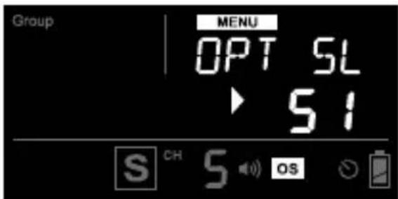
-
To turn on the optical trigger, press ↑↑↓ press the NEXT button until the text area shows
(short form for optical slave). Use the ↑r button to select S1 (FIRST) or S2 (MAIN) in the selection area. Press NEXT or ↑↓↓ confirm. -
The optical slave indicator OS will show in the status bar of the LCD display whenever any one of the optical trigger modes has been turned on.
-
To turn off the optical trigger, press the button and then the nextons until the text area shows
. Use the + or - button to choose . Press MENU or next confirm.
11.4
Delay Timer

Every RF60X is equipped with a delay timer that can be configured in either Master or Slave mode. The
delay timer delays the trigger response for the time period set. If you wish to fire the flash than the first curtain sync to create a different lighting effect (e.g. to achieve a second curtain sync), the delay timer helps you create the effect.
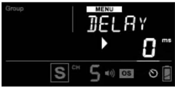
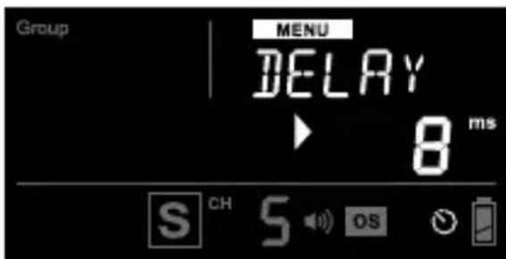
- To set the delay timer, press MENU then press the button until
is displayed and the selection indicator ▶ points to the value in ms.
-
Use the or button to set the delay timer from 1 millisecond (ms) to 99 seconds (sec).
-
Pressing and holding the + or - button will automatically speed up the key effect and make faster changes. Pressing and holding NEXT will reset the delay time to 0.
-
The delay timer indicator will show on the main screen status
bar whenever a delay timer has been set.
- To turn off the delay timer, follow steps 1-3 to set the delay time to 0. The delay timer indicator will then disappear from the status bar on the main screen.
11.5 AF-assist
The RF60X is equipped with an auto-focus (AF) assist LED. The power level of the AF-assist light can be adjusted to best suit your working environment.
-
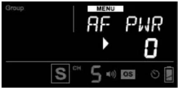
To turn on and adjust the power of the AF-assist light, press MENU and then press the NEMTton until
(short form for AF-assist power) is displayed. Use the +or button to adjust the power level from 1 to 9. The power level will apply to all Local, Master and Slave modes. -
To turn off the AF-assist light, follow step 1 and set the AF-assist power to 0.
-
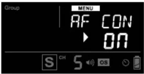
In Local or Master mode, use AF-assist continuous light. Press MENU and then press the NEXT button until
(short form for AF-assist Continuous mode) is displayed. Use the +or button to turn on or off the AF-assist continuous mode. -
In Slave mode, the RF60X will synchronize the AF-assist command with the V6 II or V6 IIs in TX mode, or the RF60X in Master mode. No setup is required.
Note: In AF-assist continuous mode, the LED light will switch off automatically before a flash is fired to prevent the AF-assist light from being exposed in the picture. The LED will switch off for one second.
12. Personalizing the RF60X
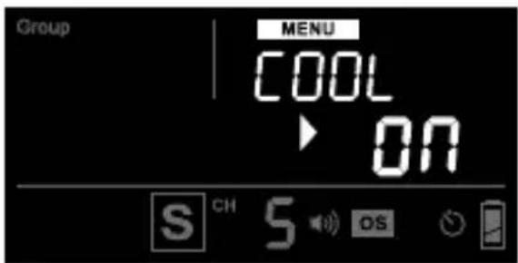
12.1 Thermal Cooling
To avoid the abrupt overheat cut-off after a series of bursts in full power, RF60X has an exclusive cooling mode to manage the temperature inside the flash body by reg the recycle time.
Cooling Mode ON:
The shortest flash recycle to be applied only when the RF60X is within moderate temperatures. The cooling mode will regulate the recycle time with reference to the temperature inside the flash a series of full-power bursts, the recycle time may become longer in later shots. However, photographers can shoot without the restriction of the overheat cut-off.
Cooling Mode OFF:
The shortest flash recycle to be applied all the time. However, the overheat cut-off may force the flash to cool down abruptly a approximately 20 full-power bursts. Photographers have to wait for 15 minutes to resume the flash operation.
-
To turn on the cooling mode, press MEN and then press the NEXT button until the text area shows
(short form for cooling mode). -
Use the +or button to turn on or off the cooling mode.
12.2 LCD Backlight
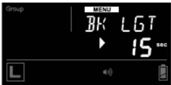
The LCD backlight of the RF60X turns on whenever any button is pressed. In order to conserve energy, there is a timer setting that automatically turns off the backlight.
-
To configure the backlight duration, press ,MENU press NEXT until the text area shows
(short form for LCD back-light). Then use the +r button to choose from 15 sec, 1 min, 15 min, or ON. -
The option
will instruct the LCD to be on constantly. -
Press tONEXconfirm and configure other items, or press MENU to confirm and leave.
12.3 Sleep Timer
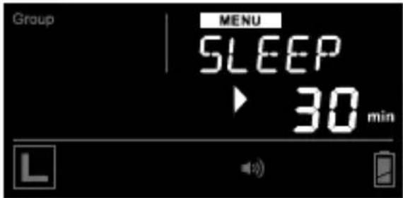
To conserve energy when you forget to switch off the RF60X after use, the sleep timer will switch the RF60X into sleep mode after a specified period.
-
To configure the sleep timer, press ME and press a fewNEXT times until the text area shows
. Then use the -or -button to choose from OFF, 3 min, 5 min, 15 min, 30 min, or 60 min. -
The option
will deactivate the sleep mode. - Press tONEXconfirm and configure other items, or press MENU to confirm and leave.
- To wake up RF60X from sleep mode, press any button once.
Note: Wireless triggering will not wake up RF60X Slave units remotely.
12.4 Quick Flash
| The quick flash option ena the RF 60 X event ho capacitor is not fully charged. |
However, the flash output may be than specified on the RF60X menu.
Enable the quick flash option with speed is more important than the accuracy of power output. Disable the quick flash option when accuracy your primary concern.
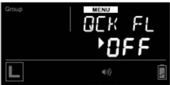
- To enable or disable the quick
flash op press, and then
NEXT until the text area shows
- Press Next confirm and configure other items, or press MENU to confirm and return to the main screen.
12.5
Beep Feedback

In addition to the flash read indicator, the built-in buzzer of the RF60X can also notify you when the flash is ready according to custom settings. Choose from the following options to best fit your shooting requirements:
OFF
RF60X does not beep in any circumstance.
Fn1* (QCK FL): Quick Flash
RF60X beeps when the flash to emit light, albeit not yet at the specified level.
Fn2 (READY): Full Charge
RF60X beeps when the flash fire at the specified level.
Fn3* (WARN): Insuff icient Power Warning
RF60X beeps only when the fired a quick flash with a power level lower than the selected level.
*Both Fn1 and Fn3 are only available for selection when the Quick Flash has been enabled (see Section 12.4)
-
To configure the beep option, press MEAND press until NEXT the text area shows
. Then use the button to choose from OFF, Fn1 (QCK FL), Fn2 (READY) or Fn3 (WARN). -
When choosing the options with the or button, the abbreviation for each option will be shown in the text area.
-
Press Next confirm and configure other items, or press MENU to confirm and leave.
-
The beep indicator will appear in the status bar whenever Fn1, Fn2, or Fn3 is selected.
13. Working with Cactus Triggers
The RF60X is compatible with Cactus Wireless Flash Transceivers V6 series, V5, and Laser Trigger LV5.
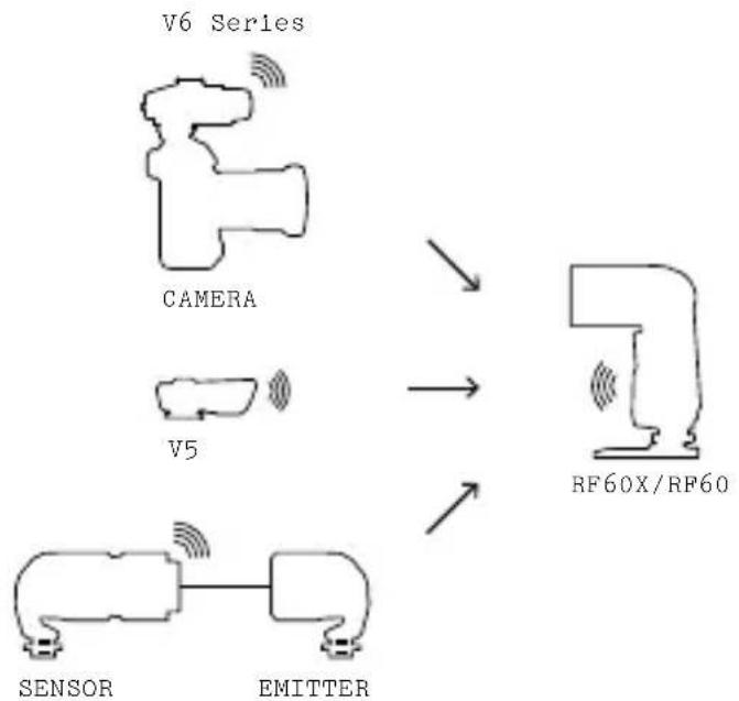
flowchart
graph TD
    A["SENSOR"] --> B["EMITTER"]
    C["CAMERA"] --> D["RF60X/RF60"]
    E["V5"] --> D
    D --> F["Output"]
13.1
Cactus V6 Series
In Slave mode, the RF60X can be commanded by the Cactus V6 series (including V6 IIs, V6 II and V6). In Master mode, the RF60X can command V6 only.
13.1.1 RF60X as Slave
With a built-in Cactus V6 RF module, the Cactus RF60X can be remotely commanded and triggered by the V6 series TX.
Note: Cactus V6 series can specify up to 1/10EV stop and communicate it with the RF60X; however, the RF60X would only display the nearest 1/3EV stop.
You may combine an RF60X with other V6-compatible TTL flashes to a manual flash control system example, assign a RF60X to group A, Canon 580EX (with a V6 II RX) to group B, Nikon SB-900 (with another V6 II RX) to group C. The V6 II TX will be able to trigger them all and set their power levels in either relative or absolute power mode.
Tip:
To support HSS of your camera system, choose V6 II or V6 IIs to automatically sync with the RF60X beyond your camera's shutter (see Section 11.2.3).
x- s y ]
13.1.2 RF60X as Master
Users may assign the RF60X as master on the camera's hot shoe and trigger and command other RF60X Slave and V6 RX units. While the RF60X Master can control the power level and zoom level of the RF60X Slave, zoom control is not supported
when working with V6 RX units.
Check the table below for the features supported in each pairing option:
| TX(Master) | RX(Slave) | Notes |
| V6 II,V6 IIs,V6 | RF60X,RF60 | √Triggering Sl 4 groups.√Changing the p and zoom level of Slaves (RX) in 4 groups.√Power levels ad from 1/128 to 1/1 full power, in the power ratio of 1/10EV, 1/3EV, 1/2EV, or 1EV (although the RF60X/RF60 will only display the nearest 1/3 s top). |
| V6 II,V6 IIs | RF60X √ | Automatic HSS for v camera systems. |
| RF60X,RF60 | V6 √T | riggering Slaves 4 groups.√Changing the p level of Slaves (RX) in 4 groups.√Power levels ad from 1/128 to 1/1 full power, with 0.3 and 0.7 increments between major power levels (in 1/3 EV power ratio).X Changing the zoom level of the Slaves (RX).X Changing in power ratios of 1/10EV, 1/2EV and 1EV.X High Speed Synchronization (HSS) |
| RF60X,RF60 | V6 II,V6 IIs | Not supported. |
13.2 Cactus V5, LV5
The Cactus RF60X can work in pairs with the Cactus V5 or LV5. They all share the same 2.4 GHz, 16-channel platform m.
SincetheV5andLV5donotsupport groupsandremotepowercontrol,the RF60XMasterwilltriggerallV5s, independentofwhichgroupit considersactive.Similarly,boththe V5andLV5willtriggeranyRF60X Slave,independentofwhatgroupit hasbeenassignedto.
14. External Power
The external powersource provides
faster recycling times and
countsperbatterycycle.
CactusExternalBatteryPackEP-1
(optional)to extend the capability
oftheRF60X:
| Recycle time after a full power flash | Number of full power flashes supported | |
| With4xAANi-MH Rechargeable Battery | 19sec170 | |
| WithCactus External Battery PackEP-1 | 12sec340 |
Forinstructionsonhowtopowerthe
RF60X with the External Battery Pack
When your flash is new or not been used for a certain period of time, the capacitor may have lost its full potential to store electricity. When this occurs, you can “form” the capacitor as follows:
- Switch on the RF60X in Local mode with fresh batteries.
- A d just the flash to full po
- Allow the ready light to glow 15 seconds to 20 seconds first.
- Fire the flash USSing the button.
- Repeat steps 3-4. After a sequence of 5 flashes, your capacitor will be formed and work as normal.
16.USBConnection
The USB port of the RF60X is designed for firmware updates.
To check the firmware version, press and hold anx switch on the RF60X at the same time.
To undergo a firmware update, switch off the RF60X and remove the batteries inside. Connect it to a computer via Cactus mini-USB cable MU-1 (optional) or a compatible USB-to-mini-USB cable. The firmware update program will then recognize
the connected RF60X and start the upgrade.
Please visit w w w.cactu s-i m a ge.com/rf60x.html for more information.
Caution:
Do not connect the RF60X to any AC power supply through the USB port.
17. Optional Accessories
- Diffuser Cap DC-60
- External Battery Pack EP-1
- Wireless Flash Transceiver V6 IIs / V6 II / V6
- Wireless Laser Trigger LV5
- 60cm Foldable Soft Box CB-60 / CB-60S / CB-60W
- Fiberglass 40" Umbrella F-401 / F-402 / F-403
- Collapsible 45" Umbrella C-451 / C-452 / C-453
- Mini-USB to USB Cable MU-1
18. Troubleshooting
Before reading this section, ensure that the Cactus RF60X has been set up correctly (follow the instructions in Sections 7-9 of this manual).
If the problem persists after completing the troubleshooting steps, contact your seller directly for further assistance.
- Flash capacitor not charging
| SYMPTOM POSSIBLE CAUSE SOLUTION | ||
| No Flash Ready Signal | Batteries are installed in wrong direction | Install batteries in the correct direction |
| Batteries are nea rly depleted or have already been used up | Replace them with a new set of AA batteries | |
| Temperature warning sig nal appears in LCD display | Too many flashes been fired in a short interval | Allow the forest for at least 15 minutes |
ash to
- Flash power turns off by itself
| SYMPTOM POSSIBLE CAUSE SOLUTION | ||
| LCD turns off | Sleep timer is activated | - Press any button on the RF60X once to wake it up from sleep mode- Check the sleep timer configuration in the Menu and revise it (see Section 12.3) |
- Local or Master flash does not fire
| SYMPTOM POSSIBLE CAUSE SOLUTION | ||
| Flash Ready LED blinks or stays on, but the does not fire | Flash is not attached securely to camera | At tach the hot shoe securely to the camera |
| Electrical contacts of the flash camera are dirty | Clean the contacts or | |
flash's
- Slave flash does not fire
| SYMPTOM POSSIBLE CAUSE SOLUTION | ||
| Flash Ready LED blinks or stays on, but the does not fire | Channel mismatch | Set Slave flash the same channel as the Master flash |
| flash Group mismatch | Make sure the group assigned to the Slave flash been activated on the Master flash | |
| Background radio interference | - Set all units to another channel or radio ID (see Section 7.7) - Change setup location as interferencemay come from other equipment in the surrounding area | |
| Master and Slave flash are placed too close to each other | Place the Master sand Slave flash at least 20cm apart and retry | |
| Beyond 100m effective range | - Make sure the Master and Slave flash are placed within 100m (328ft) of each otherNote:The effective range of 100m (328ft) may not be achieved in the presence of radio interference | |
- Flash does not fire in sync with camera
| SYMPTOM POSSIBLE CAUSE SOLUTION | ||
| Black frame appears in pictures or frame is only partially illuminated | Shutter speed is faster than the came x-sy nc limitation | - Adjust the camera's shutter speed to the maximum supported x-sync speed- Set up the RF60X in Auto HSS or Manual HSS (see Section 11.2) |
| Delay timer has been set incorrectly | Turn off the delay timer or adjust the delay timer to the correct sync time (see Section 11.4) | |
- Flash fires unexpectedly
| SYMPTOM POSSIBLE CAUSE SOLUTION | ||
| Local or Master flash misfires | Poor hot shoe connection | - Adjust tightness of hot shoe contact- Clean the R F 60 X's hot contact with a clean cloth |
| Slave flash misfires | Background radio interference | - Set all units to another channel or radio ID (see Section 7.7)- Change setup location as interference may come from other equipment in the surrounding area |
| Optical trigger has been switched on and triggered by unexpected ambient light | Switch off the optical trigger, as it may not work in the environment (see Section 11.3) | |
sh o e
- Flash power lower than specified
| SYMPTOM POSSIBLE CAUSE SOLUTION | ||
| Insufficient Power Warning bee ps (if ena bled) | Flashfires when it is not fully charged | - Turn off Quick Flash (see Section 12.4)- A llo w t h e to recharge fully |
| Ready Signal takes longer than usual to turn on | Batteries are nea rly depleted or have already been used up | Replace batteries with a new set of AA batteries |
flash
19. Notices
NOTICES FOR CUSTOMERS IN THE U.S.A.
Federal Communications Commission (FCC) Radio Frequency Interference Statements:
This equipment has been tested and found to comply with the limits for a Class B digital device, pursuant to Part 15 of the FCC Rules. These limits are designed to provide reasonable protection against harmful interference in a residential installation. This equipment generates, uses, and can radiate radio frequency energy and, if not installed and used in accordance with the instructions, may cause harmful interference to radio communications. However, there is no guarantee that interference will not occur in a particular installation.
If this equipment does cause harmful interference to radio or television reception, which can be determined by turning the equipment off and on, the user is encouraged to try to correct the interference by one or more of the following measures:
- Reorient or relocate the receiving antenna.
- Increase the separation between the equipment and receiver.
- Connect the equipment into an outlet on a circuit different from that to which the receiver is connected.
- Consult the dealer or an experienced radio/TV technician for help.
Changes or modifications not expressly approved by the party responsible for compliance could void your authority to operate the equipment.
HARVEST ONE LIMITED AND THE MANUFACTURER OF THIS WIRELESS FLASH IS NOT RESPONSIBLE FOR ANY RADIO OR TV INTERFERENCE CAUSED BY UNAUTHORIZED MODIFICATIONS TO THIS EQUIPMENT. SUCH MODIFICATIONS COULD VOID THE USER AUTHORITY TO OPERATE THE EQUIPMENT.

FCC ID: VAAFLARF60X
MADE IN CHINA
This device complies with part 15 of the FCC Rules. Operation is subject to the following two conditions: (1) this device may not cause harmful interference, and (2) this device must accept any interference received, including interference that may cause undesired operation.
R&TTE Declaration of Conformity (DOC)
We, Harvest One Limited, 11D, Block 2, Koon Wah Mirror Factory (6th) Industrial Bldg, 7-9 Ho Tin Street, Tuen Mun, Hong Kong, declare under our own responsibility that the product:
Cactus Wireless Flash RF60X
is in conformity with the essential requirements and other relevant requirements of the R&TTE Directive (1999/5/EC).

This product, Cactus Wireless Flash RF60X, is in conformity with the provisions of EU Council Directive: 1999/5/E C.
The crossed-out wheeled bin means that within the European Union the product must be disposed separately at the end of the product cycle. Do not dispose thisproduct with other municipal waste.
NCC Warning Statement
Article 12
Without permission, any company, firm or user shall not alter the frequency, increase the power, or change the characteristics and functions of the original design of the certified lower power frequency electric machinery.
Article 14
The application of low power frequency electric machineries shall not affect the navigation safety nor interfere a legal communication, if an interference is found, the service will be suspended until improvement is made and the interference no longer exists.

CCAE14LP191AT7
Japan Electrical Safety Approval

R 017-150013
20. Warranty
The limited warranty set forth below is given by Harvest One Limited with respect to the Cactus brand Wireless Flash purchased with this limited warranty.
Your Cactus Wireless Flash RF60X or other contents, when delivered to you in new condition in its original container, is warranted against defects in materials or workmanship as follows: for a period of one (1) year from the date of original purchase, defective parts or a defective Wireless Flash returned to our authorized dealers, as applicable, and proven to be defective upon inspection, will be repaired with new or comparable rebuilt parts or exchanged for a new Wireless Flash as determined by Harvest One Limited or authorized dealers.
This limited warranty shall only apply if the Wireless Flash is used in conjunction with compatible camera and flash equi which items, Harvest One Limited, shall have no responsibility.
This limited warranty covers all defects encountered in normal use of the Wireless Flash, and does not apply in any of the following cases:
(a) Loss of or damage to the Wireless Flash due to abuse, mishandling, improper packaging by you, alteration, accidents, electrical current fluctuations.
(b) Failure to follow operating, maintenance, or environmental instructions prescribed in Cactus user's manual.
(c) It is serviced by someone other than Harvest One Limited or authorized dealers.
(d) Without limiting the foregoing, water damage, sand/corrosion damage, battery leakage, dropping the flash, so abrasions or damage to the body, or damage to the hot shoe or PC cables, will be presumed to have resulted from misuse, abuse, or failure to operate the Wireless Flash as described in the operating instructions.
NO IMPLIED WARRANTY, INCLUDING ANY IMPLIED WARRANTY OF MERCHANTABILITY OR FITNESS FOR A PARTICULAR PURPOSE, APPLIES TO THE WIRELESS FLASH AFTER THE APPLICABLE PERIOD OF THE EXPRESS LIMITED WARRANTY STATED ABOVE, AND NO OTHER EXPRESS WARRANTY OR GUARANTY, EXCEPT AS MENTIONED ABOVE, GIVEN BY ANY PERSON OR ENTITY WITH RESPECT TO THE WIRELESS FLASH SHALL BIND HARVEST ONE LIMITED. HARVEST ONE LIMITED SHALL NOT BE LIABLE FOR LOSS OF REVENUES OR PROFITS, INCONVENIENCE, EXPENSE FOR SUBSTITUTE EQUIPMENT OR SERVICE, STORAGE CHARGES, LOSS OR CORRUPTION OF DATA OR ANY OTHER SPECIAL, INCIDENTAL, OR CONSEQUENTIAL DAMAGES CAUSED BY THE USE OR MISUSE OF, OR INABILITY TO USE, THE WIRELESS FLASH, REGARDLESS OF THE LEGAL THEORY ON WHICH THE CLAIM IS BASED, AND EVEN IF HARVEST ONE LIMITED HAS BEEN ADVISED OF THE POSSIBILITY OF SUCH DAMAGES. IN NO EVENT SHALL THERE BE RECOVERY OF ANY KIND AGAINST HARVEST ONE LIMITED GREATER IN AMOUNT THAN THE PURCHASE PRICE OF THE CACTUS WIRELESS FLASH SOLD BY HARVEST ONE LIMITED OR ITS AUTHORIZED DEALERS AND CAUSING THE ALLEGED DAMAGE. WITHOUT LIMITING THE FOREGOING, YOU ASSUME ALL RISK AND LIABILITY FOR LOSS, DAMAGE, OR INJURY TO YOU AND YOUR PROPERTY AND TO OTHERS AND THEIR PROPERTY ARISING OUT OF USE OR MISUSE OF, OR INABILITY TO USE, THE CACTUS WIRELESS FLASH NOT CAUSED DIRECTLY BY THE NEGLIGENCE OF HARVEST ONE LIMITED. THIS LIMITED WARRANTY SHALL NOT EXTEND TO ANYONE OTHER THAN THE ORIGINAL PURCHASER OF HARVEST ONE LIMITED, OR THE PERSON FOR WHOM IT WAS PURCHASED AS A GIFT, AND STATES YOUR EXCLUSIVE REMEDY.
Corporate Office:
HARVEST ONE LIMITED
11D, BLK 2,
KOON WAH MIRROR FACTORY (6TH) IND. BLDG.,
7-9 HO TIN ST, TUEN MUN,
HONG KONG
PLEASE CONTACT YOUR LOCAL DEALER FOR CUSTOMER SERVICE.
S C G S
- Getting to Know your RF60X
- Caution and Warnings
- Major Specifications
- Package Contents
- Nomenclature
- LCD Panel
- Getting Started
- Inserting Batteries
- Caution:
- 7.2
- Attaching the Flash to and detaching it from the Camera
- 7.3
- Turning the Flash On
- power if the flash
- Adjusting the Flash Head
- 7.5
- Bounce Card and Wide Angle Diffuser
- Using the Bounce Card
- Using the Wide Angle Diffuser
- 7.6
- Choosing the Operating Mode
- Setting the Channel and the Radio ID
- Navigating the Menu MENU
- On-camera Operation: Local Mode L
- Adjusting the Power Level
- Adjusting the Zoom Level
- Wireless Flash: Master and Slave Modes M S
- Setting up the RF60X Slave
- Commanding with the RF60X Master
- Changing Parameters of the Master Flash
- Changing Parameters of a particular Slave Group
- Changing Parameters of all Active Groups
- Turning on and off a Slave Group
- Group Aliases
- Advanced Operation
- 11.1
- Multi Flash
- MULTI
- The flash frequency the number of times t
- Notes:
- Multi Flash in Local Mode
- Multi Flash in Master and Slave Modes
- 11.2
- HSS Flash HSS
- Tip:
- Characteristics of HSS Flash
- Automatic and Manual HSS
- Automatic HSS with V6 II or V6 IIs
- Manual HSS: HSS Sympathy Mode
- Setting the Delay Time for HSS Sympathy Mode
- 11.3
- Optical Trigger os
- 11.4
- Delay Timer
- AF-assist
- Personalizing the RF60X
- Thermal Cooling
- Cooling Mode ON:
- Cooling Mode OFF:
- LCD Backlight
- Sleep Timer
- Quick Flash
- 12.5
- Beep Feedback
- OFF
- Working with Cactus Triggers
- 13.1
- Cactus V6 Series
- RF60X as Slave
- RF60X as Master
- Cactus V5, LV5
- External Power
- 16.USBConnection
- Optional Accessories
- Troubleshooting
- Notices
- NOTICES FOR CUSTOMERS IN THE U.S.A.
- R&TTE Declaration of Conformity (DOC)
- NCC Warning Statement
- Article 12
- Article 14
- Japan Electrical Safety Approval
- Warranty
- Corporate Office:
- S C G S
Brand : Cactus
Model : RF60x
Category : Flash