Monitor ST - Régulateur Dangerous Music - Free user manual and instructions
Find the device manual for free Monitor ST Dangerous Music in PDF.


User questions about Monitor ST Dangerous Music
0 question about this device. Answer the ones you know or ask your own.
Ask a new question about this device
Download the instructions for your Régulateur in PDF format for free! Find your manual Monitor ST - Dangerous Music and take your electronic device back in hand. On this page are published all the documents necessary for the use of your device. Monitor ST by Dangerous Music.
USER MANUAL Monitor ST Dangerous Music
The Dangerous Music Monitor ST-SR user's operating guide
natural_image
Electronic equipment panel with control knobs and a speaker output (no visible text or symbols)Thank you for choosing products from the exciting line of Dangerous Music recording equipment. Many years of dependable and trouble free service can be expected from our gear. This has been made possible by careful design, construction, and top shelf component choices by recording industry veterans. The Monitor ST is designed to provide quick setup of a stereo audio monitoring system complete with headphone and talkback system with the minimum of fuss. The addition of an SR module may be made at any time without rendering obsolete any part of the ST system to realize an ergonomic and great sounding surround audio monitor.
There are many functions packed into the small space of ST, SR and the Remote that controls the system. We tried to write this manual to be succinct but there is much material to cover. While the ST is easy enough to use right out of the box, reading this booklet will help the engineer to realize the full benefits of this system's function, calibration, and use.
1..... introduction
2.... safety review
3...... overview
4.... ST front panel
5.... ST rear panel
6...... connector pinouts
7. SR rear panel
8. SR front panel and alignment
9. Remote operation
13. Equipment Interface, grounding and shielding
16..... Specifications
Safety Review

The exclamation point within an equilateral triangle is intended to alert the user to the presence of important operating and maintenance (servicing) instructions in the literature accompanying this product.
Certain precautions should be taken when using electrical products. Please observe the safety hints by reading the manual and obtaining qualified help if necessary to adhere to the precautions.

- Always use a properly grounded power supply cord with this product. Please do at the ground pin on the mains plug. This connection provides earth to the chassis and sounds inside the device for clean and quiet operation.

- Avoid high temperature operation in equipment racks by providing air
circulation. The number one killer of electronic gear is HEAT. Vented rack panels may look like wasted space to an interior decorator, but they look like beauty to a technician or equipment designer! If the front panel is hot, it is roasting inside the box.

- Avoid areas of high magnetic fields. The steel chassis of ST-SR is designed to shield
the circuits from EMI and RFI (magnetic and radio interference). When installing equipment in racks, it is prudent to put power amplifiers and large power supplies at least several rack spaces, if not in a different rack, away from equipment that deals with low level signals. Separation of high level and low level equipment can pre-empt trouble caused by heat and EMI.

- The cable connecting the ST Remote to the rack unit must be a SHIELDED
Cat5-e cable. Please only use the cable that is included with the unit. Using an unshielded cable will lift the Remote ground, leaving it susceptible to damage due to static charges. If you need a longer cable run, please contact us.

- If one is uncomfortable with opening gear and changing jumpers or making ents, please seek qualified help if necessary.

- If adjustments or jumper changes are required, please disconnect the mains plug
before opening the top. Dropped screws or tools on a live circuit board can manifest themselves as burn marks and smoked components. While we feel your pain, (been there) subsequent damage is not covered by the warranty.
Dangerous Music Incorporated reserves the right to change the specifications or modify the designs of its equipment. Sending in the registration card is our way of keeping in touch with users of our equipment should this become necessary. Registration information is always kept confidential and never disclosed to third parties for any reason. Company contact information is on the last page of this manual.

The CE sign on this product signifies the fact that ST-SR have been tested and verified to conform to the applicable standards of 89/336/EEC. EN55103-1 (emissions) EN61000-2 (immunity) and EN60065:2002 (safety requirements)

This product uses components of the types and quantities that comply with the EC RoHS standard 2002/95/EC. A list of suppliers and materials is available from DMI. We tightly control production to use top quality materials.
2002/95/EC
Overview
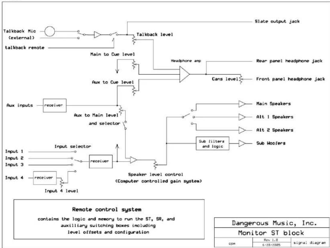
This signal block diagram gives an overall view of the flow in ST. The following pages have back panel and front panel views to help in hooking up and adjusting the box. Addition of the SR surround module is covered. The next section gives details of the remote software and operation. Finally, a discourse on grounding, shielding, and making installation go correctly is provided.
It was decided during the design to use no Digitally Controlled Amplifiers or Voltage Controlled Amplifiers for level control. While DCAs are cheap and convenient, the designers do not think that the sound quality shortcomings made up the difference and developed a computer controlled transmission line attenuator for the main level controls. This was (as usual) an expensive alternative but provides accurate level control, repeatability, and in these designer's views, the best sounding approach to remotely controllable level adjustment available. In addition, the Computer Controlled Gain System makes it easy for the end user to trim gains on individual inputs and speaker outputs without the hassle or need of test gear to properly calibrate pots, other than an SPL meter for the initial setup of the surround speakers. Interface with -10dBV and +4dBu equipment is a button push away rendering the Semi/Pro gear problem a non-issue.
flowchart
graph TD
    A["talkback Mio (external)"] --> B["Main to Cue level"]
    C["talkback remote"] --> B
    B --> D["Aux to Cue level"]
    D --> E["Aux inputs"]
    E --> F["receiver"]
    F --> G["Aux to Main level and selector"]
    G --> H["Speaker level control (Computer controlled gain system)"]
    I["Input 1"] --> J["Input selector"]
    K["Input 2"] --> L["receiver"]
    M["Input 3"] --> L
    N["Input 4"] --> O["receiver"]
    O --> P["Input 4 level"]
    Q["Slate output jack"] --> R["Talkback level"]
    S["Rear panel headphone jack"] --> T["Headphone amp"]
    U["Front panel headphone jack"] --> V["Cans level"]
    W["Main Speakers"] --> X["Sub filters and logic"]
    Y["Alt 1 Speakers"] --> Z["Speaker level control"]
    AA["Alt 2 Speakers"] --> Z
    AB["Sub Woofers"] --> AC["Speaker level control"]
    AD["Dangerous Music, Inc."] --> AE["Monitor ST block"]
    AF["cpm"] --> AG["Rev 1.8"]
    AG --> AH["6/28/2005"]
    AH --> AI["signal diagram"]
Monitor ST front panel
Controls will be explained in order from left to right

text_image
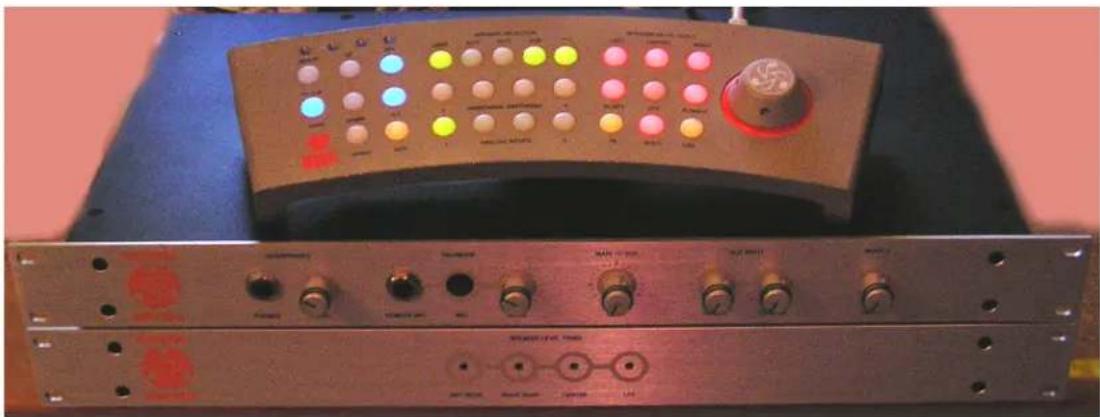
DANGEROUS MONITOR ST HEADPHONES PHONES LEVEL TALMEACK REMOTE NO. NO. LEVEL MAIN TO CUE LEVEL AUX INPUT TO GIVE TO MAIN INPUT 4 -12 LEVEL 0The Phones jack is for the engineer to hear what is going out to the talent's headphones. The Level control adjusts only the front jack level. Please start with the level control down low as the amplifier is very powerful. Typically 2:00 to 4:00 is a good position with today's medium impedance cans (32-70 ohms).
The Talkback section has a mic, an external mic jack, and a level control that lives comfortably around 4:00 usually. The Remote Mic jack is designed to receive a high impedance mic level. An inexpensive line transformer (600-10k ohms) will get an SM57 up to the level that the electret element feeds the talkback system. The built in mic has surprisingly good pickup and fidelity and as such, an external mic would be needed only if the rack unit is in a closet or enclosed rack of some sort.
The Main to Cue Level control sends the selected input source to the cue amp. 2:00 is a normal position to start with for this control.
The Aux Input level controls send the aux input to Cue or Main. There is an Aux to Main Enable switch on the remote to turn on the Aux signal in the control room speakers (to check the click track or listen to what is coming out of the headphone jack on the computer, for instance).
The Input 4 Level pot turns down the input 4 source as necessary. It is exactly unity gain when full up. It is provided for this scenario:
You are doing a mix and a client hands you a mastered CD that he wants your mix to 'sound like'. Obviously, the level is pretty serious and you know there is no way that your mix level should even be within 8 dB of this mastered CD. Fortunately, your CD player is plugged into Input 4 and you can turn the level down of the CD player so you can compare the CD to your mix and not look foolish to the unknowing guy who handed you the mix to compare. Since your mix isn't smashed within a inch of its life, it will actually sound more dynamic than the mastered CD anyway until your project gets mastered and smashed within an inch of its life...
When using input 4 in surround, the control should be set fully clockwise.
Monitor ST rear panel

text_image
1 AND INPUTS 2 INPUT OUTPUT DO IN TO REMOTE SLATE GUE AMP OUT REMOTE STARTED REMOTE AT ALL REMOTABLE POTTER YOURING WITH UP PENTHING FULLER REMOTE FOR MEDICAL WMHIND FOR MOUNTED REMOTEThe Aux Inputs feed the main and cue amp sections and can be used for many purposes. Three that come to mind immediately are:
- Mult the vocal mic/EQ/comp signal being fed to the DAW into Aux Inputs for latency free vocals in the cue system.
- Feed the audio output of your Mac's enclosure into the Aux input to hear computer sound previews.
- Use a mini mixer for both of the above and a click for voice overs and drummer cue feeds, etc.
- Set a mic/pre combo up in the recording room for duplex comm during talkback.
Main inputs and outputs:
The Monitor ST uses 25 way 'D' connectors for the main input and output connections wired according to the Tascam standard. The signals are arranged on the connectors as follows (wiring diagrams on next page).
Input 1 Left and Right on channels 1+2
Input 2 Left and Right on channels 3+4
Input 3 Left and Right on channels 5+6
Input 4 Left and Right on channels 7+8
Speaker 1 Left and Right on channels 1+2
Speaker 2 Left and Right on channels 3+4
Speaker 3 Left and Right on channels 5+6
Sub woofers Left and Right on channels 7+8
DC IN is for the power supply. Don't hot plug this connector as that will arc the contacts.
TB REMOTE is provided for using a producer's remote switch available from us or wired according to the diagram on the next page.
The SLATE output feeds the talkback mic to the DAW or external powered speakers for cueing the talent. Please note that this signal is unaffected by the TB level control.
The CUE AMP OUT jack feeds a Redco Little Red Cue Box or similar level control device for talent headphones. www.redco.com
The REMOTE jack hooks up to the remote with shielded CAT 5-e cable that can be up to 100 feet long. Don't plug this into a router or computer- it's not an Ethernet connection. Please use only the cable supplied by Dangerous. An unshielded cable lifts the remote ground, leaving your remote susceptible to damage from static charges, and it will void your warranty. If you need a longer cable run, or have any questions, please contact us.
The TB Remote connector fires the talkback circuit if pin 2 is connected to pin 3. Putting a switch on the end of a mic cable can give someone else in the control room the means to operate the talkback circuit. Using the TB Remote does not dim the control room speakers.
The Cue Amp Out is wired:
Pin 1 common ground
Pin 2 Right amp
Pin 3 Left amp
'D' connector pin out
| pin # | Channel | signal |
| 1 | 8 | high |
| 14 | 8 | low |
| 2 | 8 | shield |
| 15 | 7 | high |
| 3 | 7 | low |
| 16 | 7 | shield |
| 4 | 6 | high |
| 17 | 6 | low |
| 5 | 6 | shield |
| 18 | 5 | high |
| 6 | 5 | low |
| 19 | 5 | shield |
| 7 | 4 | high |
| 20 | 4 | low |
| 8 | 4 | shield |
| 21 | 3 | high |
| 9 | 3 | low |
| 22 | 3 | shield |
| 10 | 2 | high |
| 23 | 2 | low |
| 11 | 2 | shield |
| 24 | 1 | high |
| 12 | 1 | low |
| 25 | 1 | shield |
| 13 | not used | |
natural_image
Close-up of a network device rear panel with multiple USB connectors and cable bands (no visible text or symbols)SR-ST linked together
The Cue Amp Out jack is compatible with several passive headphone level control boxes from Redco, Whirlwind, ProCo, and others.
SR rear panel

flowchart
graph LR
    A["INPUT 1"] --> B["SPERKER 1"]
    C["INPUT 2"] --> D["SPERKER 2"]
    E["INPUT 3"] --> F["SPERKER 3/SUB"]
    G["INPUT 4"] --> H["METER FEED"]
    I["TO MONITOR ST"] --> J["FROM MONITOR ST"]
    K["REMOTE IN"] --> L["REMOTE THWD"]
    M["DO IN"] --> N["DELEND"]
    O["SEMICONDUCTOR MONITOR ON SLA AND ANNULIFE REVEY POWER NEUTRAL SWITCH"] --> P["OUTPUT OF DETAILING THE MULTIPOLIC PREDUCTOR CE"]
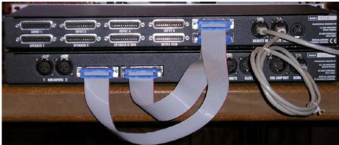
The ‘D’ connectors use the same pin configuration as on the previous page. When the SR is combined with the ST, 2 ribbon cables are connected between them using the ‘To Monitor ST’ and ‘From Monitor ST’ jacks. The remote is plugged into the Remote In jack and a short jumper is run from the Remote Thru to the Remote In jack on the ST unit. The ST then becomes the controller for the left and right front channels in a 5.1 surround system. The other connectors are:
Inputs 1-4
| Signal channel |
| Left Front 1 |
| Right Front 2 |
| Left Rear 3 |
| Right Rear 4 |
| Center 5 |
| LFE 6 |
Channels 7&8 are unused.
Speaker 1&2 use the same configuration. The SR can accommodate up to 2 surround speaker sets this way.
Speaker 3/Sub
| Signal channel | |
| Left Front 1 | |
| Right Front 2 | |
| open 3 | |
| open 4 | |
| open 5 | |
| Sub/LFE mono 6 | |
| Sub/LFE left 7 | |
| Sub/LFE right 8 |
The 3^rd speaker output has a stereo feed for the front channels and a unique feature to switch signals for the subwoofers in the system. In Stereo mode, the Sub feeds get their signal from the front channels, output 6 having a mono combiner for systems with one subwoofer. In surround, the Sub/LFE outputs send the LFE channel signal to the subs. This facilitates easy accommodation of systems with one or two subwoofers and combined with the roll-off function and level offsets on the ST, allows easy setup of signal assignment, realizing the full potential of various speaker setups.
The selected input feeds the Meter Feed jack, channels 1-6.
SR front panel

flowchart
graph LR
    A["SOCKET"] --> B["Left Rear"]
    A --> C["Front Rear"]
    A --> D["Center"]
    A --> E["Life"]
The four holes on the front panel are for level trims to adjust the balance between the front speakers (controlled by ST) and the surround speakers. The order on the panel is Left Rear, Right Rear, Center, and LFE.
The alignment procedure requires the procurement of a Sound Pressure Level meter and a pink noise generator. There have been many attempts to come up with a practical alignment that covers all the different manufacturer's methods of properly aligning a surround system. Sometimes there is conflicting information. In our work at Sterling Sound, the principals at Dangerous Music have tried to define an alignment standard that satisfies the requirements for mastering in a surround environment while accommodating the sometimes conflicting information available to do so. As such, we believe that we have a pretty good procedure but are certain that some people would disagree with certain aspects. Such is the state of the art in surround facility setup these days. The only suggestion we can offer is to set the system up as described here and tweek it according to your studio requirements, good judgment, and experience.
Run pink noise into all 6 channels and solo the Left Front. Adjust the volume to obtain an spl of roughly 80 dB at the listening position. Solo the Center channel and adjust the 3^rd pot on SR to read the same. Solo the Rear Left and Right channels one at a time and adjust similarly. Solo the sub and adjust it for a level roughly 6 dB down from the others. This puts the energy band of 20-200 Hz in approximately the same magnitude as the other speakers. The spl meter should be measuring level in the ‘Flat’ or ‘C’ mode weighting.
Play some surround DVDs that you are familiar with and tweak sub levels to taste. One will notice that Sub levels differ with format, type of work (movies, multi-channel audio, Dolby or DTS, etc.) and mastering facility preference room configuration and sub placement. This results from the differing standards and the issue of who is correct is difficult to rectify as of this date. The Audio Engineering Society has taken a stab at defining the issues.
http://www.aes.org/technical/documents/AESTD1001.pdf
The Recording Academy has also made an attempt at defining the setup of surround equipment. There are differences in these two attempts mainly in the proper setup of subwoofer levels (specifically, the 10 dB boost in some home theater sound decoders) and channel assignment (easily rearranged in the DAW I/O routing setup). http://www.grammy.com/pe_wing/5_1_Rec.pdf
Monitor ST Remote
text_image
SPEAKER SELECTION SEPTUS UP PP MAIN ALTI ALTE 3.50 - BEET GAIN DOWN 6.1 1 ADDITIONAL SWITCHING 4 R LEFT LFE R RIGHT MONO AUX ANALOG INPUTS 4 TR POLO DIM SPEAKER MUTE / SOLD LEFT CENTER RIGHTHere is a brief description of how the remote works:
There are two ways to activate buttons in this system. For descriptive purposes, I'll call the two actions either a Press or a Hold.
A Press means pushing the button for less than 12 a second, a short duration push. A Hold means keeping the button down for more than a second, then releasing it.
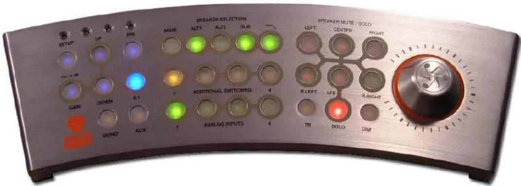
Remote boots up in about a second when power is applied to the ST or it is hot plugged to a powered up ST. The remote always boots up with Input 1, Main Speaker, and Dim selected. If audio sources and speakers are hooked up to the ST, pressing the Dim button will set the unit into normal operation mode. The Volume control is an Absolute Position Encoder (as opposed to the cheesy, ubiquitous, continuous rotary encoders everywhere) so where it points is where the volume is, just like the good old days. The difference to the good old days is that the encoder controls a Computer Controlled Gain System that accurately sets the volume in all speaker systems under all conditions to within 0.02dB. The difference to the good new days is that the CCGS does not use VCA's or DCA's so the sound quality is strikingly good and consistent at all gain settings. This is no small achievement. A quick rundown of the functions is in order. The buttons are color coded to organize the functions into groups.
Blues are for programming gain offsets and system configurations.
Greens are for input source, speaker selection, and subwoofer/filter assignments.
Orange switches provide Mono, Aux to Main signal engagement, Talkback, and Dim.
Reds are for speaker Mute/Solo functions.
I'll start at the end and finish at the beginning!
Play with the mute buttons for a while to get used to what we call Momentoggle, the difference between a press and a hold. You will notice that if you hold a mute button, the speaker will silence and come back on when the button is released. If the same mute button is pressed, the function will latch and the speaker will stay silent until the button is pressed again. It is good to get familiar with the timing of Momentoggle. If the Solo button is held to engagement, pressing a button for a particular speaker silences the rest. In other words, the Solo function logically inverts the Mute functions. This is not that functional in stereo but in surround, solos with multiple latchings become good for diagnostic listening purposes.
The Orange buttons engage listening functions. The Mono button adds the left and right channel and presents the sum up the middle of the speakers. The Aux to Main button lets the signal present at the Auxiliary Input jacks mix into the selected Input signal. There is a level control on the ST front panel to set the mix. The Talkback button dims the selected and aux signals in the speakers and headphones and engages the microphone so that the talent can hear the engineer complaining about pronunciation and intonation or timing. The Talkback Level control on the ST front panel sets the mic level in TB mode. The Dim button lowers the selected speaker gain by 18 dB. The Additional Switching buttons are for selecting sources on a future Dangerous Music box that will have video and/or audio selectors. The Talkback and Dim buttons are under the spell of Momentoggle.
The Green buttons select the input source, speaker system, subwoofer, and low pass filter for the sub. The factory default settings for gain and subwoofer management are unity gains and no subwoofer or filter engagement. One can turn the subs and/or filters on but when a different speaker system is selected, the factory defaults will rule again until the user programs the system with the Blue buttons.
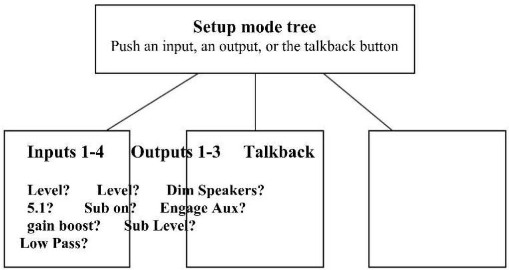
Setup Mode
Changing input gains, speaker system gains, subwoofer enabling/level offsets, and filtering options are done in Setup mode. To enter, hold the Setup button for 1 second and release. The blue light stays on indicating that the computer is ready for programming. Holding the button again will exit Setup mode storing any changes that are made to system configuration or gain. Pressing the PPI button while in Setup mode will reboot the computer without saving changes and holding the PPI button while pressing the LFE mute button then releasing the two will reset the memory back to the factory defaults (useful when one wants to start from a known system configuration).
flowchart
graph TD
    A["Setup mode tree\nPush an input, an output, or the talkback button"] --> B["Inputs 1-4\nLevel? Level? Dim Speakers?\n5.1? Sub on? Engage Aux?\ngain boost? Sub Level?\nLow Pass?"]
    A --> C["Outputs 1-3\nTalkback"]
    A --> D["End"]
Input Setup Mode (Level, 5.1?, gain for -10dBV device?)
Enter Setup mode and press an input button that you want to configure. One will notice that a green light is on above the Setup LED. The Up/Down buttons will step the volume control and Red LEDs will indicate where you are from where you were (green LED stays lit from the stored gain position). One can compare different inputs and alter gain settings of any input until a match of all inputs is achieved. The other input configurations during this process are the Gain and 5.1 buttons. The Gain button brings the input selected up to pro level if it is a -10dBV device (RCA connectors on a DVD player). The 5.1 button tells the system that the input under selection is a surround device which Route the LFE signal to the subwoofer and enables the surround channels.
Holding the Setup button after input programming is complete will store gain and configuration settings. One doesn't need to exit Setup before proceeding to output configurations.
Output Setup Mode (Level, Sub on, Sub level, Low Pass Filter)
While in Setup mode, speaker outputs can be set for relative levels between speaker systems with the Up/Down buttons much the same as gains were controlled at the inputs. The difference is that output gains are treated as a pad. This was done for sound quality reasons. Outputs can have the subwoofer assigned to engage when that output is selected by pressing the Sub button. The Sub can have a Low Pass Filter assigned also to chase midrange completely out of the sub so it doesn't interfere with the main speakers, as desired. Pressing the Sub button allows one to alter the subwoofer level relative to the speaker selected with the Up/Down buttons.
Pressing the Sub button twice while in setup mode disengages the subwoofer for that speaker, indicated by the Sub LED extinguishing. The Low Pass Filter is disengaged the same way. If this all sounds complicated, it really is easier to sit down with the remote and plug around with the buttons for a few minutes. It will all become easy after messing with the system.
Remember to hold the setup button to exit and store the configuration and gain changes. If the memory becomes completely and hopelessly entangled (yours or the systems), one can reset the system to factory defaults by simultaneously holding the PPI and LFE mute buttons and then letting go.
Talkback Setup (Speaker Dim and Aux input enable)
The talkback function can be programmed to dim the main speaker level (producer's talkback) or not (conductor's talkback). The factory default mode is for producer's talkback. Enter Setup mode and hold the Talkback button. Press the Dim button to toggle between modes and exit setup to store your choice. The Talkback Remote jack on the rear panel engages conductor's talkback only. The Aux input can be enabled with talkback to set up a 'listen back' microphone for the control room for 2 way communications or to provide Muzak to sooth the guitar player as you berate him for the amount of editing it will take to get his part right.
Adding a small “pocket mixer” to the Aux Input can be a convenient way to patch and mix signals into the ST system. The mixer can set the Listen Back mic level, the computer cue (headphone out) level, and still have inputs left over for a click track and other signals.
The PPI function
The PPI button does toggle during normal use and is the ubiquitous Producer Pacification Indicator. It is used for situations where the producer wants just one more change to a mix that you think is perfect. You look him in the eye and say, “Do you like it like this… or This (while pressing the PPI button)”. The annoying producer will usually pick one of the conditions (blue light on for This mix) and you can print the mix as you had it and move on…
Quick Mute Cancel
Pressing the Setup button briefly (not long enough to engage Setup Mode) will cancel any mutes that may be toggled on.
Equipment Interface and other audio gear lore
The Difference between Grounds and Shields
While the usual scenario in hooking up equipment is that one plugs in the cables and starts to work, the more complicated a system, the more likely it is that something will not work correctly as far as hum and noise performance is concerned. While some would blame the equipment, this is the equivalent of blaming the eggs for a bad soufflé. Usually, hum and noise problems (and jitter or clock troubles in digital interfaces) can be traced to poor planning and implementation of the studio's grounding situation.
It is illuminating to realize that the engineers of yore in the recording, broadcast, and communications industries have been through these troubles and figured out the solutions. History can teach us a lot about how to avoid ground loops and their associated problems. The manuals of many test instrument and recording equipment manufacturers from the ‘50’s to the 80’s had chapters on how to fix (or to avoid from the start) hum and noise problems and it is from this wealth of information that this writer draws ideas from for trouble free grounding schemes.
To comply with international standards and wiring practices, recording equipment manufacturers are required to connect all the shield pins of audio and data connectors to the chassis grounds of their gear. Sometimes, this can cause noise problems in large systems where pieces of equipment are spread out around a facility because two ‘grounds’ are never quite at the same potential. This can cause ground loops (hums or buzzing in the speakers) if the cable shields are allowed to connect two chassis that are at different potentials due to location, circuit wiring, or induction.
If the audio cables between the racks connect the equipment grounds together via the shields and the racks are at even slightly different potentials (on different circuits with different loads, long distance, etc) the shields will try to equalize the potential difference.

flowchart
graph LR
    A["outlet A"] --> B["Rack-o-Stuff"]
    B --> C["interconnecting cables"]
    C --> D["Another Rack-o-Stuff"]
    D --> E["outlet B"]
    B --> F["Ground Loop current"]
    D --> F
    B --> G["Mains grounds meet at the power panel"]
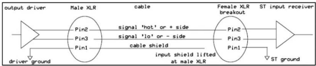
Juice will flow down the shields and broadcast hum into the signal wires they were supposed to protect or wind up imposed on the reference ground of the receiving equipment. This situation manifests itself as the all too familiar buzz of a ‘ground loop’. The intensity depends on many variables but can go from unnoticeable to raging. Some people in desperation resort to using AC plug “ground lifts” to defeat the mains safety grounds in a random fashion until the system quiets down a bit. This in our view (and the view of the international safety standards organizations) is an unacceptable method of taming ground buzzes. The simpler way is to make sure that all the gear has a good mains ground and to lift the shields on the receiving ends of the audio cables. The principals at Dangerous Music have wired up large, world class facilities using this scheme and have brought room after room online with no buzz problems from the moment of power up. This is why many gear manufacturers have shield lift jumpers inside their equipment. If a noise problem crops up, changing the jumper position will almost always cure the problem. Planning out the wiring system to minimize the formation of ground loops solves problems before they happen.
In contrast to other devices in a recording system, many powered speakers seem to get their audio reference ground from the input cable. This means that these shields should not be lifted at the XLR.
Our favored technique for trouble shooting buzz issues is to make a short XLR cable with the shield lifted on the male connector and use this to test whether or not an XLR interface warrants a shield lift.
The ST Remote however, must always use a shielded cable/connector (please use the one supplied by Dangerous). Failing to do so will void your warranty. Using an unshielded cable will leave the remote susceptible to static discharge, which can cause damage.
Do I turn my gear off at night?
This is a good question and one that takes some reflection to answer. There are several issues to be weighed in making the decision of what to do with unattended gear. Equipment that is powered down when the facility is not in use can't be damaged by power problems short of a direct lightning strike, however, turn-on transients can, over time, lower the reliability of equipment because of inrush current spikes. On the other hand, a room left powered and unattended can result in blown speakers if the power company has problems and there is no one to turn the room off. If one lives in a stable power situation (non-rural or power-conditioned), our preference is to leave the monitor section, A/D converters, and solid state power amps on unless the facility will not be used for a time.
Over the years, the experience of the Dangerous team has been that gear left on is more stable in performance and sound quality, and doesn't really cost very much in extra power consumed. Solid state amps and converters can take several hours to stabilize in temperature and the sound quality is a moving target while things are warming up. Having said that, the writer has come home to his studio and found smoked speaker cones (bummer) due to Con Edison power switching problems. This issue is a tough call and really situation dependant. Studios that power down daily can lose a piece of gear now and then to the rough reality of daily power-up. The repair bill is likely more than the extra electricity consumed had the equipment stayed on.
Balanced Audio Connections
flowchart
graph LR
    A["output driver"] --> B["Male XLR"]
    B --> C["Female XLR breakout"]
    C --> D["ST input receiver"]
    E["driver ground"] --> B
    F["ST ground"] --> C
    B -->|pin1| G["pin1"]
    B -->|pin2| H["pin2"]
    B -->|pin3| I["pin3"]
    B -->|pin1| J["pin1"]
    B -->|pin2| K["pin2"]
    B -->|pin3| L["pin3"]
    B -->|pin1| M["pin1"]
    B -->|pin2| N["pin2"]
    B -->|pin3| O["pin3"]
    B -->|pin1| P["pin1"]
    B -->|pin2| Q["pin2"]
    B -->|pin3| R["pin3"]
    B -->|pin1| S["pin1"]
    B -->|pin2| T["pin2"]
    B -->|pin3| U["pin3"]
    B -->|pin1| V["pin1"]
    B -->|pin2| W["pin2"]
    B -->|pin3| X["pin3"]
    B -->|pin1| Y["pin1"]
    B -->|pin2| Z["pin2"]
    B -->|pin3| AA["pin3"]
    B -->|pin1| AB["pin1"]
    B -->|pin2| AC["pin2"]
    B -->|pin3| AD["pin3"]
    B -->|pin1| AE["pin1"]
    B -->|pin2| AF["pin2"]
    B -->|pin3| AG["pin3"]
    B -->|pin1| AH["pin1"]
    B -->|pin2| AI["pin2"]
    B -->|pin3| AJ["pin3"]
    B -->|pin1| AK["pin1"]
    B -->|pin2| AL["pin2"]
    B -->|pin3| AM["pin3"]
    B -->|pin1| AN["pin1"]
    B -->|pin2| AO["pin2"]
    B -->|pin3| AP["pin3"]
    B -->|pin1| AQ["pin1"]
    B -->|pin2| AR["pin2"]
    B -->|pin3| AS["pin3"]
    B -->|pin1| AT["pin1"]
    B -->|pin2| AU["pin2"]
    B -->|pin3| AV["pin3"]
    B -->|pin1| AW["pin1"]
    B -->|pin2| AX["pin2"]
    B -->|pin3| AY["pin3"]
    B -->|pin1| AZ["pin1"]
    B -->|pin2| BA["pin2"]
    B -->|pin3| BB["pin3"]
    B -->|pin1| BC["pin1"]
    B -->|pin2| BD["pin2"]
    B -->|pin3| BE["pin3"]
The beauty of balanced connections is that they promote the idea that current should be prevented from flowing down cable shields while letting the audio pass. Pins 2 and 3 carry a signal across them (transverse mode) and any interference that gets through the shield is picked up equally by the wires (common mode). The common mode noise is canceled by the differential action of the instrumentation amplifiers in the first stage of the Monitor. Signal gets through and the grounds stay put inside their respective pieces of gear. This is why most professional equipment uses balanced interfaces. Huge, complicated systems can be set up and still be trouble free, as opposed to ‘Free Trouble’!
Unbalanced Audio Connections
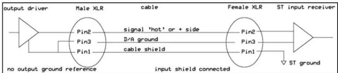
An unbalanced source driving a Monitor ST input usually presents no problem because of the differential action of the input stage.

flowchart
graph LR
    A["output driver"] --> B["driver ground"]
    B --> C["Male XLR Pin2"]
    C --> D["signal 'hot' or + side"]
    D --> E["D/A ground"]
    E --> F["cable shield"]
    F --> G["Female XLR breakout Pin2"]
    G --> H["ST input receiver"]
    H --> I["ST ground"]
    C --> J["Pin3 Pin1"]
    J --> K["input shield lifted at male XLR"]
It is a good idea to use 3 wire cables even in an unbalanced situation because the Monitor input can keep stray noise away from the signal even without the benefit of common mode rejection. If an unbalanced source gives one trouble, then this is usually because the source doesn't have a proper ground reference. One can be provided by simply leaving the shield connected.
flowchart
graph LR
    A["output driver"] --> B["Male XLR"]
    B --> C["ST input receiver"]
    B --> D["no output ground reference"]
    B --> E["signal 'hot' or + side"]
    B --> F["D/A ground"]
    B --> G["cable shield"]
    B --> H["ST ground"]
    B --> I["Input shield connected"]
    B --> J["Female XLR"]
If one is not using breakout cables, i.e. wiring straight to custom 'D' connectors, these decisions are made at the 'D' connectors on the ST inputs.
Specifications
Frequency response 1Hz - 100 kHz within 0.2dB
THD+Noise 0.002%
IMD60 4:1 0.003%
Low Pass Filter.... 57Hz, 3 pole Bessel/Chebyshev hybrid
Interchannel crosstalk -95dB
Dynamic range 110dB
Maximum level +25dBu
Nominal operating level ....+4dBu
Power consumption 30 watts
Warranty ...... Free 2 year extended warranty with online registration.
Standard warranty: 90 days parts and labor, subject to inspection. Does not include damage incurred through abusive operation or modifications/attempted repair by unauthorized technicians.
USA Europe
Dangerous Music, Inc. Dangerous Music, Inc.
Dangerous Music, Inc. reserves the right to alter the software and design of their equipment. If after reading the manual more information for an application is needed, please contact us by email for the quickest response. Factory contact must also happen before shipping a unit to us for service. Please keep the original cartons in case storage or transportation of units is necessary and always insure shipment as mechanical damage is not covered by the warranty.