Liaison - Mixing console Dangerous Music - Free user manual and instructions
Find the device manual for free Liaison Dangerous Music in PDF.


User questions about Liaison Dangerous Music
0 question about this device. Answer the ones you know or ask your own.
Ask a new question about this device
Download the instructions for your Mixing console in PDF format for free! Find your manual Liaison - Dangerous Music and take your electronic device back in hand. On this page are published all the documents necessary for the use of your device. Liaison by Dangerous Music.
USER MANUAL Liaison Dangerous Music
text_image
Polarity Blend Polarity INSERT 0 SEND RETURN L RUSER GUIDE
LIAISON®
The Audio Neural Network
text_image
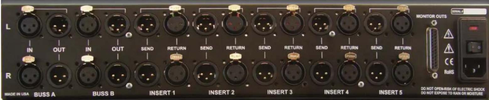
L IN OUT IN OUT SEND RETURN SEND RETURN SEND RETURN SEND RETURN SEND RETURN SEND RETURN SEND RETURN SEND RETURN R MADE IN USA BUSS A BUSS B INSERT 1 INSERT 2 INSERT 3 INSERT 4 INSERT 5 MONITOR OUTS SERIAL F A C E RoHS DO NOT OPEN-RISK OF ELECTRIC SHOCK DO NOT EXPOSE TO RAIN OR MOISTURE
SAFETY REVIEW
The Exclamation point within an equilateral triangle is intended to alert the user to the presence of important operating and maintenance (servicing) instructions in the literature accompanying this product
Certain precautions should be taken when using electrical products. Please observe the safety hints by reading the manual and obtaining qualified help if necessary to adhere to the precautions.

- Always use a properly grounded power supply cord with this product. Please do not defeat the ground pin on the mains plug. This connection provides earth to the chassis and signal grounds inside the device for clean and quiet operation.

- Avoid high temperature operation in equipment racks by providing air circulation. The number one killer of electronic gear is HEAT. Vented rack panels may look like wasted space to an interior decorator, but they look like beauty to a technician or equipment designer! If the front panel is hot, it is roasting inside the box.

- Avoid areas of high magnetic fields. The steel chassis is designed to shield the circuits from EMI and RFI (magnetic and radio interference). When installing equipment in racks, it is prudent to put power amplifiers and large power supplies at least several rack spaces, if not in a different rack, away from equipment that deals with low level signals. Separation of high level and low level equipment can pre-empt trouble caused by heat and EMI.

- Care should be taken to avoid liquid spills around equipment. If a spill occurs, please shut off the gear and disconnect the mains. A qualified technician should investigate accidents to prevent further equipment damage or personnel hazards caused by spills.

- If one is uncomfortable with opening gear and changing jumpers or making adjustments, please seek qualified help if necessary.

- If adjustments or jumper changes are required, please disconnect the mains plug before opening the top. Dropped screws or tools on a live circuit board can manifest themselves as burn marks and smoked components. While we feel your pain, (been there) subsequent damage is not covered by the warranty.
Dangerous Music Incorporated reserves the right to change the specifications or modify the designs of its equipment. Sending in the registration card is our way of keeping in touch with users of our equipment should this become necessary. Registration information is always kept confidential and never disclosed to third parties for any reason. Company contact information is on the last page of this manual.

The CE sign on this product signifies the fact that the Additional Switching System® has been tested and verified to conform to the applicable standards of 89/336/EEC.EN55103-1 (emissions) EN61000-2 (immunity) and EN60065:2002 (safety requirements)

This product uses components of the types and quantities that comply with the EC RoHS standard 2002/95/EC. A list of suppliers and materials is available from DMI. We tightly control production to use top quality materials.
2002/95/EC

text_image
iiiREAD THIS FIRST

text_image
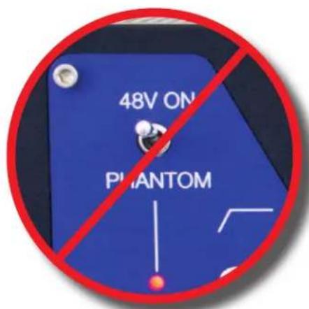
Yellow triangular warning sign with black exclamation mark symbolDO NOT INCORRECTLY CONNECT MIC PREAMPS TO THE LIAISON!
To avoid damaging your hard won gear and voiding your warranty, follow the simple steps below.
- Do not connect gear equipped with phantom power- such as mic preamps and channel strips - to the insert loops in your Liaison. Activating the phantom power will damage the electronics in the monitor and parallel processing paths and void the warranty instantly!
It may also damage other outboard gear that is parked down-stream of the offending piece by applying the phantom power to the inputs.
A mic pre output as the source connected to either Buss A or Buss B Input is perfectly OK - phantom power is applied to the INPUT pins of a mic pre.
Correct Path: Mic > Mic Pre Input > Mic Pre Line Out > Liaison Buss Input
- If you cannot follow the first rule and choose to connect a mic preamp to the Liaison inserts, DO NOT engage the phantom power.
The Dangerous Music Team

DANGEROUS
MUSIC
text_image
48V ON PHANTOMTABLE OF CONTENTS
| Overview | 1 | |
| Liaison Rear Panel Features & Benefits | 1 | |
| Liaison Front Panel Features, Benefits & Connection | 2 | |
| Liaison Application Notes | 10-16 | |
| Specifications | 17 | |
| Warranty | 18 | |
THANK YOU
Thank you for choosing products from the exciting and innovative line of Dangerous Music recording equipment. Many years of reliable service can be expected from our gear. This is made possible through careful design, construction, and component choices by recording industry veterans.
The Dangerous Music Liaison is designed to increase productivity and improve the creative process by unleashing the potential of your outboard gear arsenal. There are comprehensive tips and application notes in this user's guide, so don't skip the read.
If you have any suggestions for future products, feel free to forward them!

"Audio Integrity: non-negotiable." This is the credo upon which Dangerous Music is founded. Conceived and designed by end users—not by engineers in lab coats— the results are products that resurrect dynamic range, punch, intelligibility and emotion. These high-fidelity, uncompromising signal paths are achieved by harnessing over 20 years of Chris Muth's design wizardry; creator of infamous custom black boxes for world class facilities like Hit Factory, Masterdisk, Absolute Audio and Sterling Sound Mastering. Then the critical listening skills of golden-eared luminaries are applied, with the result being musical tools that fulfill the actual needs of today's flexible computer based studio.
OVERVIEW
To survive in this modern day audio jungle, the contemporary studio must be flexible and agile; a facility that can adapt to any workflow, effortlessly. Tracking, mixing and mastering services oftentimes must be performed under one roof, utilizing every piece of outboard gear available.
The Dangerous Liaison realizes this dream by providing unprecedented access to your outboard equipment. Connect up to six of your favorite units to the Liaison (more if you daisy chain, leverage a patchbay or add a Dangerous Master). Instantly audition any device or combination, change the order, dial in some parallel processing and then store these customized signal paths as presets to use again, on demand, anytime. True hard-wire bypass relays remove the gear entirely from the signal path; this includes outboard that lacks an integrated bypass or true hard-wire bypass. Mastering grade components switch instantly and silently, providing true A/B comparisons without coloration or latency. Pre and post-processing monitor outputs make it simple to audition between the original source and the treated product.

text_image
DANGEROUS LIAISON 1 2 3 4 5 6 PRETOLER BEANS INSERT 6 SEND OPEN 1 2 3 4 5 6 PRETOLER BEANS 1 2 3 4 5 6 PRETOLER BEANS 1 2 3 4 5 6 PRETOLER BEANS 1 2 3 4 5 6 PRETOLER BEANS 1 2 3 4 5 6 PRETOLER BEANS 1 2 3 4 5 6 PRETOLER BEANS 1 2Unpack this audio traffic tower and celebrate! Inside the box you'll find the Liaison and a standard 3 Pin IEC power cable and the manual you're reading now.
Note: We recommend reading the entire manual. This box is deep and you just spent a pile of cash, so why just wade in the shallow end?
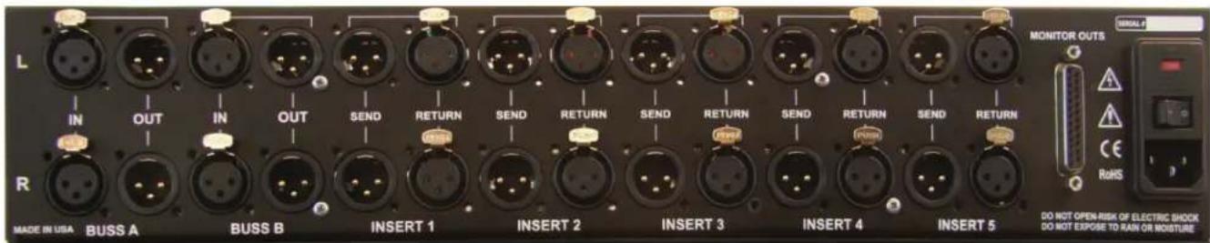
Liaison: Rear Panel Connections
text_image
L IN OUT IN OUT SEND RETURN SEND RETURN SEND RETURN SEND RETURN SEND RETURN SEND RETURN SEND RETURN R MADE IN USA BUSS A BUSS B INSERT 1 INSERT 2 INSERT 3 INSERT 4 INSERT 5 MONITOR OUTS A A CE RoHS DO NOT OPEN-RISK OF ELECTRIC SHOCK DO NOT EXPOSE TO RAIN OR MOBISTURE[REAR PANEL INPUTS AND OUTPUTS PICTURED ABOVE]
1. INPUTS & OUTPUTS
Feature: Premium grade XLR Connectors.
Benefit: More surface area for happy electrons to migrate through and no off shore, cheap look alike connectors that "almost" fit.
Note: All connections wired pin 2 hot as per AES standards.
Feature: DB25 Connector.
Benefit: Screws in and locks, plus we ran out of room on the rear of the unit for 4 more stereo outputs!
Tip: Cables DO make a difference. Ask for Mogami 2534 interconnects.
2. A/C CABLE & SWITCHING
text_image
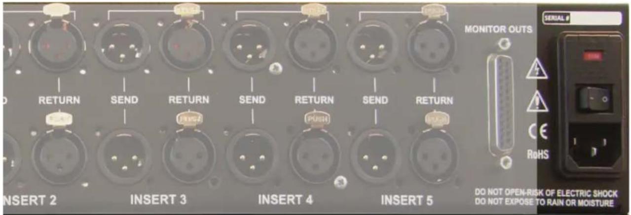
RETURN SEND RETURN SEND RETURN SEND RETURN RETURN RETURN INSERT 2 INSERT 3 INSERT 4 INSERT 5 MONITOR OUTS SERIAL # DO NOT OPEN-RISK OF ELECTRIC SHOCK DO NOT EXPOSE TO RAIN OR MOISTURE[REAR PANEL POWER SECTION PICTURED ABOVE]
Feature: Three pin IEC cable.
Benefit: Simple to replace if lost.
Feature: Selectable voltage.
Benefit: Travel with the Liaison everywhere in the world, connecting the ultimate collection of gear and making friends.
Operation: Please review the mains voltage in the red window before plugging in the unit or electrifying events may transpire. To change it, use a screwdriver to gently pry the mains inlet module's cover open and flip the fuse block around so the correct voltage appears in the window.
Tip: The power switch is on the inlet module. Seat the AC cable completely and use properly grounded power mains for safe and quiet operation.
Tip: √ If the Liaison will not power on and the power is known to be good, check the fuses under the inlet module's cover. Use 500 milliamp fast blow for 120V (America) and 250 milliamp fast blow for 240V (Europe).
- INSERTS: INPUTS & OUTPUTS

text_image
SEND RETURN SEND RETURN SEND RETURN SEND RETURN INSERT 1 INSERT 2 INSERT 3 INSERT 4 INSERT 5[REAR PANEL INSERT SECTION PICTURED ABOVE]
Feature: Connect outboard equipment here (i.e. compressor, limiter, eq, reverb...)
Benefit: Individually selectable via the front panel of the unit (more to follow on this).
Feature: Separate send and return cables, each on XLR.
Benefit: Standard issue, readily available cables.
Tip: The ability to loop multiple pieces of gear on a single insert if desired (i.e. comp and limiter back to back).
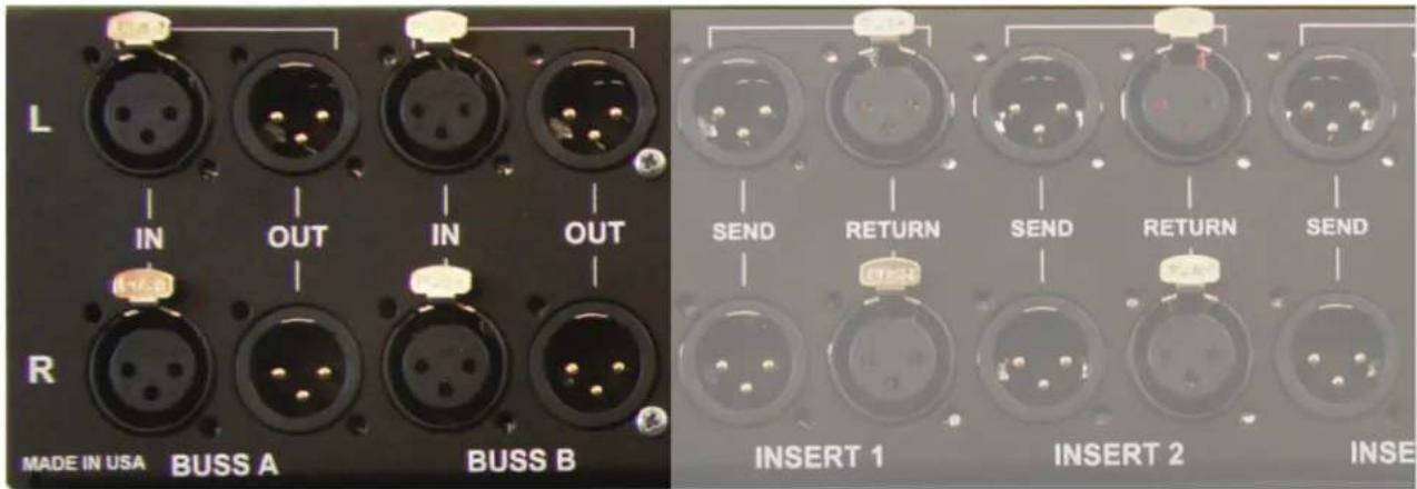
- BUSS A & B: INPUTS & OUTPUTS
text_image
L IN OUT IN OUT R MADE IN USA BUSS A BUSS B SEND RETURN SEND RETURN SEND INSERT 1 INSERT 2 INSE[REAR PANEL BUSS SECTION PICTURED ABOVE]
Feature: Individual access in and out to both BUSS A & BUSS B
Benefit: Leverage all your outboard gear twice, on two discrete buss paths. For example, take the output of your favorite mic preamp and send it to BUSS A. Then send the signal into your session. Meanwhile, connect the output of your mix to BUSS B. Now all of your gear is accessible all the time for tracking, mixing and mastering.
Tip: ☑: Take the output of of BUSS A and connect it to the input of BUSS B to make one contiguous chain. This will allow outboard that is connected later, to appear earlier. For example... the BAX EQ is in INSERT 1 and the Variable Mu™
Limiter is in INSERT 5. Selecting BUSS A'S INSERT 5 and BUSS B'S INSERT 1, the Variable Mu™ will now receive audio before the BAX EQ.
Operation: Press insert button 5 on BUSS A and insert button 1 on BUSS B.
Tip: 🚆 There is an additional insert, INSERT 6, located on the front panel.
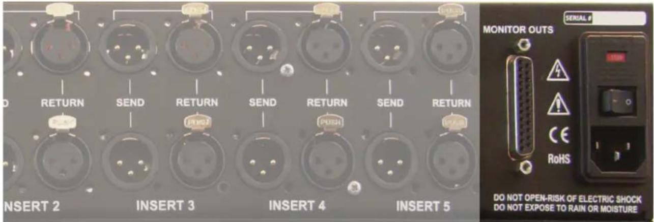
5. MONITOR OUTPUTS
text_image
RETURN SEND RETURN SEND RETURN SEND RETURN INSERT 2 INSERT 3 INSERT 4 INSERT 5 MONITOR OUTS SERIAL # DO NOT OPEN-RISK OF ELECTRIC SHOCK DO NOT EXPOSE TO RAIN OR MOISTURE[REAR PANEL MONITOR OUTPUT SECTION PICTURED ABOVE]
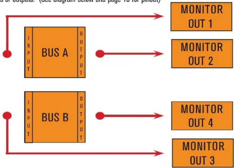
Feature: 4 stereo outputs that provide input and output monitoring of each Buss.
Benefit: Listen before the outboard gear of BUSS A, or after, or before the outboard gear of BUSS B, or after to determine whether the fruits of you labor are helping or hindering your efforts toward audio nirvana.
Tip: √ When used in stand alone mode, you may monitor Buss A input (preprocessing) and Buss B output (post processing)
Tip: ✅ MONITOR OUTS are tapped off the busses (pre BUSS A, post BUSS A, pre BUSS B, post BUSS B) and do not affect the main bus inputs or outputs. (See diagram below and page 10 for pinout)
flowchart
graph TD
    A[" Bus A "] --> B[" Monitor OUT 1 "]
    A --> C[" Monitor OUT 2 "]
    D[" Bus B "] --> E[" Monitor OUT 3 "]
    D --> F[" Monitor OUT 4 "]
    A --> G[" INPUT "]
    D --> H[" INPUT "]
    G --> I[" OUTPUT "]
    H --> J[" OUTPUT "]
Liaison: Front Panel Features & Benefits
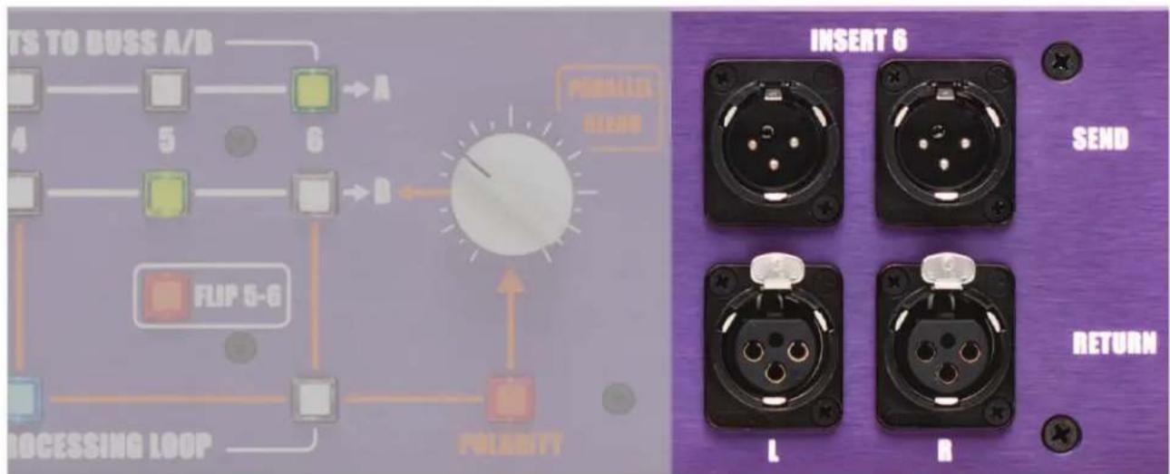
1. ADDITIONAL INSERT 6
text_image
TS TO BISS A/B 4 5 6 PUMLESS HEAD FLIP 5-6 PROCESSING LOOP POLARITY INSERT 6 SEND RETURN L R[ADDITIONAL INSERT SIX PICTURED ABOVE]
Feature: Connect additional outboard equipment here (i.e. client's favorite, rented, begged, borrowed or...)
Benefit: Individually selectable via the front panel of the unit (more to follow on this).
Feature: Separate send and return cables, each on XLR.
Benefit: Standard issue, readily available cables.
Tip: The ability to loop multiple pieces of gear on a single insert if desired (i.e. comp and limiter back to back).
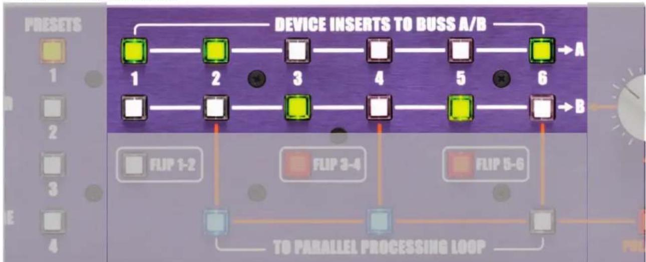
2. DEVICE INSERTS TO BUSS A/B
flowchart
graph TD
    A["1"] --> B["2"]
    B --> C["3"]
    C --> D["4"]
    D --> E["5"]
    E --> F["6"]
    F --> G["A"]
    F --> H["B"]
    I["FLIP 1-2"] --> J["TO PARALLEL PROCESSING LOOP"]
    K["FLIP 3-4"] --> J
    L["FLIP 5-6"] --> J
[DEVICE INSERTS AND BUSSES PICTURED ABOVE]
Feature: Instantly and silently switch between outboard processors.
Benefit: The human ear has a remarkably fleeting memory. Echoic memory studies have resulted in up to 4 seconds of retention. Unfortunately these are based on vocal cues (random word sequences) vs. audio auditions. The latter have resulted in only up to 1000 milliseconds. That means no time for a patchbay or clumsy manual jack swaps. The Liaison provides true, instantaneous comparisons with no disconcerting pops and thuds.
Feature: True Hard-Wire Bypass Relays.
Benefit: When an insert is in bypass, the outboard unit is completely out of the circuit. This is the same as strapping an incredibly short cable between the insert points- all circuitry is avoided.
Tip: √ Even if the equipment itself does not have a True Hard-Wire Bypass, the Liaison provides it.
Feature: Color coded: Green = Engaged; White = Bypassed
Benefit: Visual confirmation of equipment activated.
3. BUSS A & B
Feature: Apply your outboard gear on two completely discrete stereo busses.
Benefit: Leverage all your outboard gear twice, on two discrete buss paths. For example, take the output of your favorite mic preamp and send it to BUSS A. Then send the signal into your session. Meanwhile, connect the output of your mix to BUSS B. Now all of your gear is accessible all the time for tracking, mixing and mastering.
Operation: Both Busses can be provided with input individually. Their respective outputs must be wired to the destination.
Tip: ☑: Take the output of of BUSS A and connect it to the input of BUSS B to make one contiguous chain. This will allow outboard that is connected later, to appear earlier. For example... the BAX EQ is in INSERT 1 and the Variable Mu™ Limiter is in INSERT 5. Selecting BUSS A'S INSERT 5 and BUSS B'S INSERT 1, the Variable Mu™ will now receive audio before the BAX EQ.
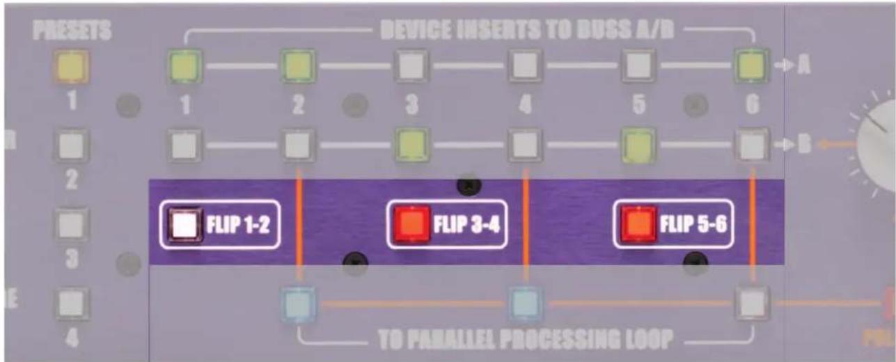
4. THE FLIP BUTTONS
flowchart
graph TD
    A["1"] --> B["2"]
    B --> C["3"]
    C --> D["4"]
    D --> E["5"]
    E --> F["6"]
    G["FLIP 1-2"] --> H["FLIP 3-4"]
    I["FLIP 5-6"] --> J["TO PARALLEL PROCESSING LOOP"]
[FLIP BUTTONS PICTURED ABOVE]
Feature: For both BUSS A and BUSS B, the FLIP BUTTONS reverse the position of the inserts in pairs.
Benefit: For example, to answer the age old mastering question of "what should come first, my equalizer or limiter?" let's say the Variable Mu™ limiter is in INSERT 1 and the BAX EQ is in INSERT 2. To audition them in reverse order, simply hit the FLIP 1-2 switch. Now you are monitoring the BAX EQ into the Variable Mu™ limiter.
Tip: ☑: Want to take advantage of PARALLEL PROCESSING for the Variable Mu™ limiter in the above example? Since the PARALLEL PROCESSING LOOP affects whatever processor is positioned in the even numbered inserts (i.e. 2, 4 and 6), and the Variable Mu™ limiter is connected to INSERT 1, simply reverse the order of the inserts with the FLIP 1-2 switch and take advantage of actions like the blending of extreme limiting or compression. Now the INSERT 1 BUTTON will blink slowly, indicating it's activation in the PARALLEL PROCESSING LOOP.
Tip: ☑: The FLIP BUTTONS affect both BUSS A and BUSS B simultaneously.
5. THE PARALLEL PROCESSING LOOP BUTTONS

flowchart
graph TD
    A["Device Inserts to Duss A/B"] --> B["1"]
    A --> C["2"]
    A --> D["3"]
    A --> E["4"]
    A --> F["5"]
    A --> G["6"]
    B --> H["FLIP 1-2"]
    C --> I["FLIP 3-4"]
    D --> J["FLIP 5-G"]
    E --> K["TO PARALLEL PROCESSING LOOP"]
    F --> L["Polarity"]
    G --> M["Polarity"]
    N["Polarity"] --> O["PARALLEL ALONG"]
    P["Polarity"] --> Q["Polarity"]
[PARALLEL PROCESSING LOOP BUTTONS PICTURED ABOVE]
Feature: PARALLEL PROCESSING LOOP for the outboard equipment positioned in the even numbered inserts (i.e. 2, 4 and 6).
Benefit: PARALLEL PROCESSING allows the original and effected signals to be blended independently. See tips below.
Tip: Example 1: crush the drums with heavy compression for tight, explosive impact, while mixing in the original to retain transients and dynamics.
Tip: Example 2: add a touch of reverb to an entire mix to pull the group together in one space.
Tip: Example 3: blend a dash of the original, unprocessed signal into the end of the chain for clarity.
Tip: Example 4: mix in Dolby A in encode only to add some air (i.e. lead vocal on Journey's, "Don't Stop Believing" or for a more extreme example, Def Leppard Hysteria background vocals).
Operation: Depress the PARALLEL PROCESSING LOOP button to select the appropriate piece of outboard gear and engage FLIP BUTTONS as needed.
Tip: ☑: Want to take advantage of PARALLEL PROCESSING for INSERT 1, not INSERT 2? Simply reverse the order of the inserts with the
FLIP 1-2 switch. Now the INSERT 1 BUTTON will blink slowly, indicating it's activation in the PARALLEL PROCESSING LOOP.
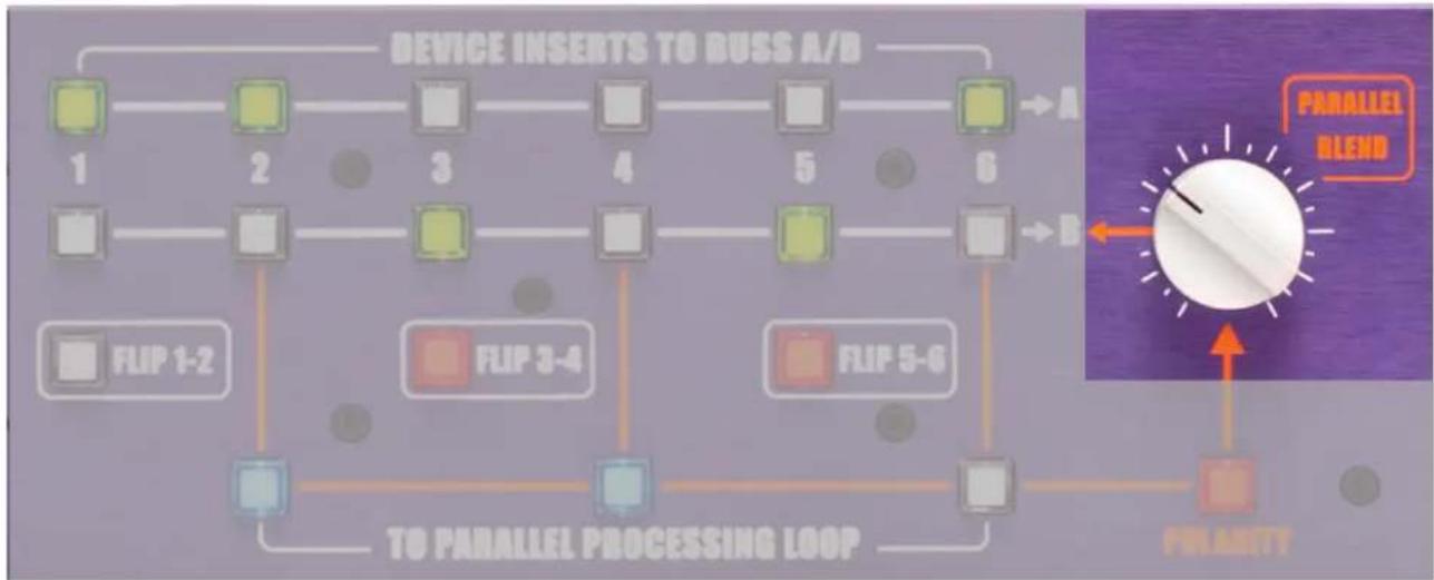
6. PARALLEL PROCESSING LOOP BLEND CONTROL
flowchart
graph TD
    A["1"] --> B["2"]
    B --> C["3"]
    C --> D["4"]
    D --> E["5"]
    E --> F["6"]
    F --> G["TO PARALLEL PROCESSING LOOP"]
    G --> H["FLIP 1-2"]
    H --> I["FLIP 3-4"]
    I --> J["FLIP 5-6"]
    J --> K["FLIP 5-6"]
    K --> L["FLIP 5-6"]
    L --> M["FLIP 5-6"]
    M --> N["FLIP 5-6"]
    N --> O["FLIP 5-6"]
    O --> P["FLIP 5-6"]
    P --> Q["FLIP 5-6"]
    Q --> R["FLIP 5-6"]
    R --> S["FLIP 5-6"]
    S --> T["FLIP 5-6"]
    T --> U["FLIP 5-6"]
    U --> V["FLIP 5-6"]
    V --> W["FLIP 5-6"]
    W --> X["FLIP 5-6"]
    X --> Y["FLIP 5-6"]
    Y --> Z["FLIP 5-6"]
    Z --> AA["FLIP 5-6"]
    AA --> AB["FLIP 5-6"]
    AB --> AC["FLIP 5-6"]
    AC --> AD["FLIP 5-6"]
    AD --> AE["FLIP 5-6"]
    AE --> AF["FLIP 5-6"]
    AF --> AG["FLIP 5-6"]
    AG --> AH["FLIP 5-6"]
    AH --> AI["FLIP 5-6"]
    AI --> AJ["FLIP 5-6"]
    AJ --> AK["FLIP 5-6"]
    AK --> AL["FLIP 5-6"]
    AL --> AM["FLIP 5-6"]
    AM --> AN["FLIP 5-6"]
    AN --> AO["FLIP 5-6"]
    AO --> AP["FLIP 5-6"]
    AP --> AQ["FLIP 5-6"]
    AQ --> AR["FLIP 5-6"]
    AR --> AS["FLIP 5-6"]
    AS --> AT["FLIP 5-6"]
    AT --> AU["FLIP 5-6"]
    AU --> AV["FLIP 5-6"]
    AV --> AW["FLIP 5-6"]
    AW --> AX["FLIP 5-6"]
    AX --> AY["FLIP 5-6"]
    AY --> AZ["FLIP 5-6"]
    AZ --> BA["FLIP 5-6"]
    BA --> BB["FLIP 5-6"]
    BB --> BC["FLIP 5-6"]
    BC --> BD["FLIP 5-6"]
    BD --> BE["FLIP 5-6"]
    BE --> BF["FLIP 5-6"]
    BF --> BG["FLIP 5-6"]
    BG --> BH["FLIP 5-6"]
    BH --> BI["FLIP 5-6"]
    BI --> BJ["FLIP 5-6"]
    BJ --> BK["FLIP 5-6"]
    BK --> BL["FLIP 5-6"]
    BL --> BM["FLIP 5-6"]
    BM --> BN["FLIP 5-6"]
    BN --> BO["FLIP 5-6"]
    BO --> BP["FLIP 5-6"]
    BP --> BQ["FLIP 5-6"]
    BQ --> BR["FLIP 5-6"]
    BR --> BS["FLIP 5-6"]
    BS --> BT["FLIP 5-6"]
    BT --> BU["FLIP 5-6"]
    BU --> BV["FLIP 5-6"]
    BV --> BW["FLIP 5-6"]
    BW --> BX["FLIP 5-6"]
    BX --> BY["FLIP 5-6"]
    BY --> BZ["FLIP 5-6"]
    BZ --> CA["FLIP 5-6"]
    CA --> CB["FLIP 5-6"]
    CB --> CC["FLIP 5-6"]
    CC --> CD["FLIP 5-6"]
    CD --> CE["FLIP 5-6"]
    CE --> CF["FLIP 5-6"]
    CF --> CG["FLIP 5-6"]
    CG --> CH["FLIP 5-6"]
    CH --> CI["FLIP 5-6"]
    CI --> CJ["FLIP 5-6"]
    CJ --> CK["FLIP 5-6"]
    CK --> CR["FLIP 5-6"]
    CR --> CS["FLIP 5-6"]
    CS --> CT["FLIP 5-6"]
    CT --> CU["FLIP 5-6"]
    CU --> CV["FLIP 5-6"]
    CV --> CW["FLIP 5-6"]
    CW --> CX["FLIP 5-6"]
    CX --> CY["FLIP 5-6"]
    CY --> CZ["FLIP 5-6"]
[PARALLEL PROCESSING LOOP BLEND CONTROL PICTURED ABOVE]
Feature: PARALLEL PROCESSING amount controlled by a CONTINUOUSLY VARIABLE POTENTIOMETER.
Benefit: Dictates the amount of direct (non-effected) or processed (effected) signal that is sent to the end of Buss B. See examples in item 4 above for application suggestions.
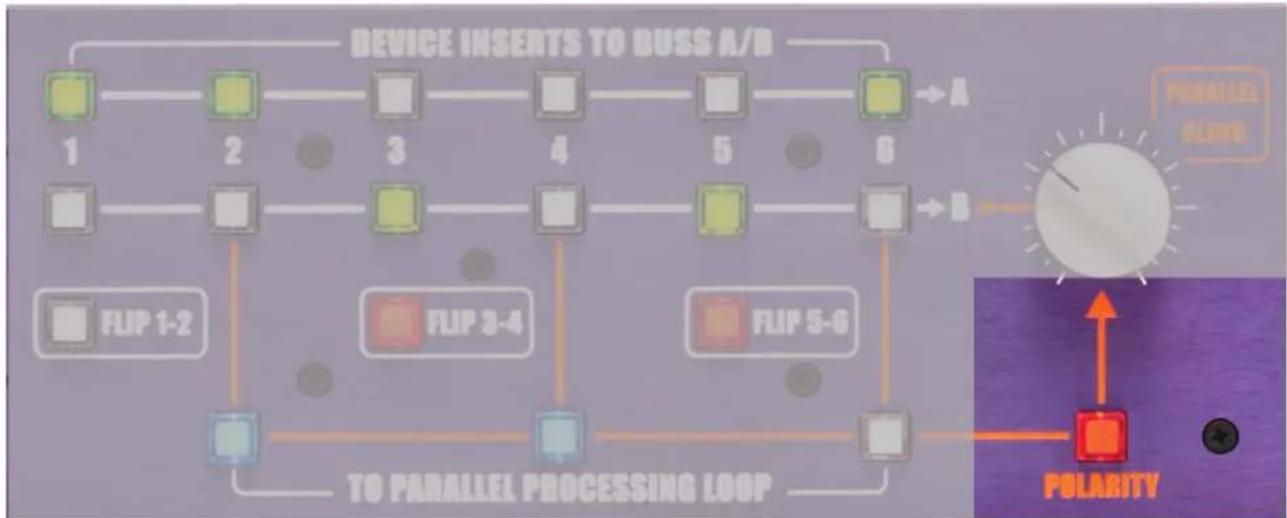
7. POLARITY BUTTON
flowchart
graph TD
    A["Device Inserts TO BUSS A/D"] --> B["1"]
    B --> C["2"]
    C --> D["3"]
    D --> E["4"]
    E --> F["5"]
    F --> G["6"]
    G --> H["→A"]
    H --> I["→B"]
    I --> J["FLIP 1-2"]
    J --> K["TO PARALLEL PROCESSING LOOP"]
    K --> L["FLIP 3-4"]
    L --> M["FLIP 5-6"]
    M --> N["POLARITY"]
    N --> O["Polarization"]
    style A fill:#f9f,stroke:#333
    style G fill:#f9f,stroke:#333
    style I fill:#ccf,stroke:#333
[POLARITY BUTTON PICTURED ABOVE]
Feature: Reverse the polarity 180 degrees.
LIAISON | 9
Benefit: Something out of phase? Fix it. Need to dial something OUT of the mix? Add it here 180° out of phase and select the amount.
Tip: √ As an effect: compress the mix and flip it out of phase to hear it pump in time with the track.
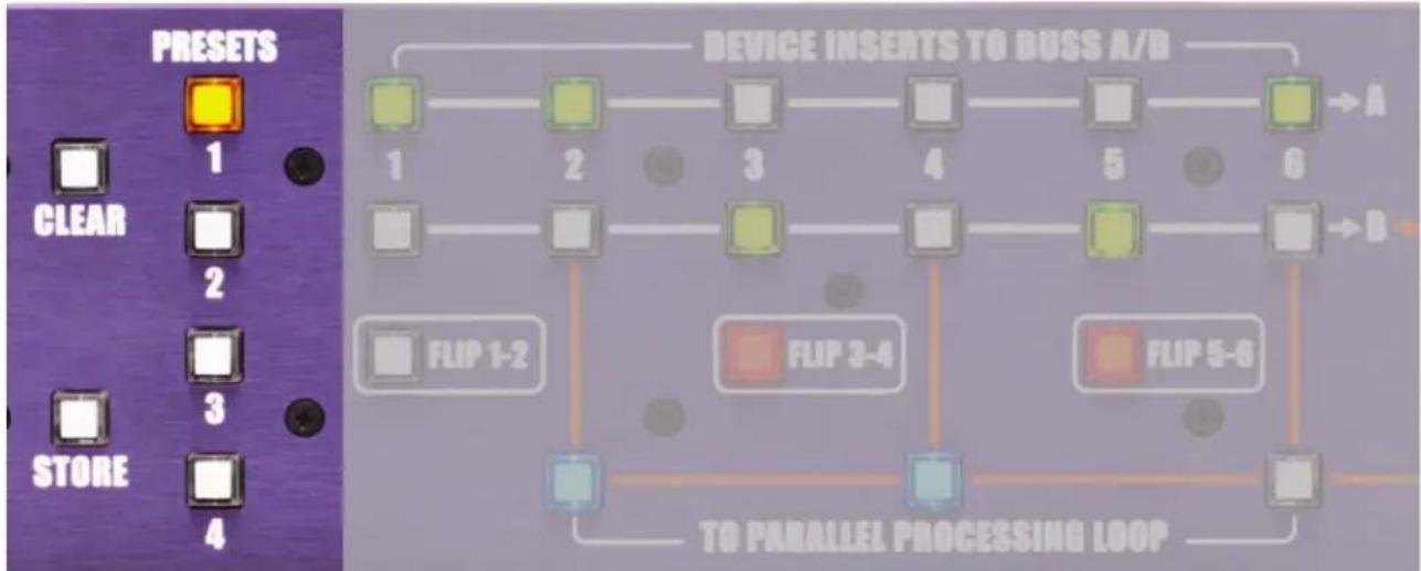
8. PRESET, CLEAR & STORE BUTTONS
flowchart
graph TD
    A["1"] --> B["2"]
    B --> C["3"]
    C --> D["4"]
    D --> E["5"]
    E --> F["6"]
    G["1"] --> H["2"]
    H --> I["3"]
    I --> J["4"]
    J --> K["5"]
    K --> L["6"]
    M["FLIP 1-2"] --> N["TO PARALLEL PROCESSING LOOP"]
    O["FLIP 3-4"] --> P["TO PARALLEL PROCESSING LOOP"]
    Q["FLIP 5-6"] --> R["TO PARALLEL PROCESSING LOOP"]
    S["1"] --> T["2"]
    T --> U["3"]
    U --> V["4"]
    V --> W["5"]
    W --> X["6"]
    Y["1"] --> Z["2"]
    Z --> AA["3"]
    AA --> AB["4"]
    AB --> AC["5"]
    AC --> AD["6"]
    AE["1"] --> AF["2"]
    AF --> AG["3"]
    AG --> AH["4"]
    AH --> AI["5"]
    AI --> AJ["6"]
    AK["1"] --> AL["2"]
    AL --> AM["3"]
    AM --> AN["4"]
    AN --> AO["5"]
    AO --> AP["6"]
[PRESET, CLEAR AND STORE BUTTONS PICTURED ABOVE]
Feature: STORE or CLEAR up to four patches.
Benefit: Have a favorite vocal processing chain? Master Buss sweetening path? Mastering outboard winning combination? Store all those proven success combinations and recall them instantly on demand.
Operation: To STORE a PRESET, select whatever combination of switches desired, press the store button (it will blink) and then depress the desired preset location.
To CLEAR a PRESET, simply select clear, then press store and the preset you'd like to clear.
Tip: After a PRESET has been stored, changing any settings will cause the PRESET BUTTON to blink. Depressing the PRESET BUTTON will toggle between the stored PRESET (solid light) and modified PRESET (blinking light). Effectively doubling the memory locations to 8. If desired, store the altered PRESET.
Tip: Create presets as starting points. For example, when tracking, create your favorite vocal path, kick drum path etc... For the mix buss or mastering store presets for different musical styles (Hip Hop, Rock, Pop, Jazz, Gregorian Chant...)
Liaison: Application Examples
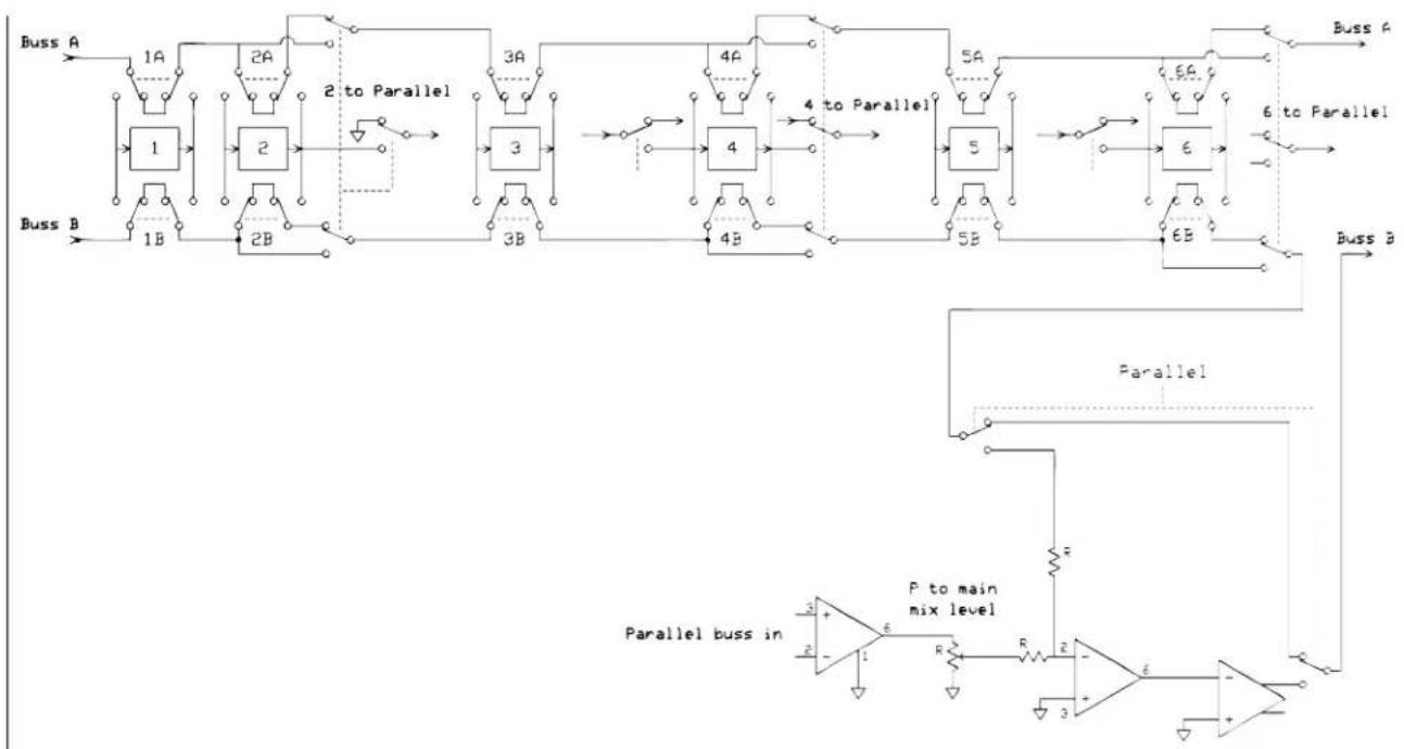
- BLOCK DIAGRAM
flowchart
graph TD
    A["Buss A"] --> B["1A"]
    B --> C["1"]
    C --> D["2A"]
    D --> E["2 to Parallel"]
    E --> F["3A"]
    F --> G["3B"]
    G --> H["4A"]
    H --> I["4"]
    I --> J["5A"]
    J --> K["5B"]
    K --> L["6B"]
    L --> M["Buss B"]
    N["Buss B"] --> O["1B"]
    O --> P["2B"]
    P --> Q["3B"]
    Q --> R["4B"]
    R --> S["5B"]
    S --> T["6B"]
    T --> U["Buss A"]
    V["Buss A"] --> W["1A"]
    X["Buss B"] --> Y["1B"]
    Z["Buss B"] --> AA["2B"]
    AB["Buss A"] --> AC["1A"]
    AD["Buss B"] --> AE["1B"]
    AF["Buss B"] --> AG["2B"]
    AH["Buss A"] --> AI["1A"]
    AJ["Buss B"] --> AK["2B"]
    AL["Buss B"] --> AM["3B"]
    AN["Buss A"] --> AO["1A"]
    AP["Buss B"] --> AQ["1B"]
    AR["Buss B"] --> AS["2B"]
    AT["Buss A"] --> AU["1A"]
    AV["Buss B"] --> AW["2B"]
    AX["Buss B"] --> AY["3B"]
    AZ["Buss A"] --> BA["1A"]
    BB["Buss B"] --> BC["1B"]
    BD["Buss B"] --> BE["2B"]
    BF["Buss A"] --> BG["1A"]
    BH["Buss B"] --> BI["1B"]
    BJ["Buss B"] --> BK["2B"]
    BL["Buss A"] --> BM["1A"]
    BN["Buss B"] --> BO["2B"]
    BP["Buss B"] --> BQ["3B"]
    BR["Buss A"] --> BS["1A"]
    BT["Buss B"] --> BU["1B"]
    BV["Buss B"] --> BW["2B"]
    BX["Buss A"] --> BY["1A"]
    BZ["Buss B"] --> CA["2B"]
    CB["Buss B"] --> CD["3B"]
    CE["Buss A"] --> CF["1A"]
    GD["Buss B"] --> DH["1B"]
    DI["Buss B"] --> DJ["2B"]
    DK["Buss A"] --> DL["1A"]
    DM["Buss B"] --> DE["1B"]
    DF["Buss B"] --> DG["2B"]
    DH --> DH
    DG --> DH
    DH --> DH
    DH --> DH
    DH --> DH
    DH --> DH
    DH --> DH
    DH --> DH
    DH --> DH
    DH --> DH
    DH --> DH
    DH --> DH
    DH --> DH
    DH --> DH
    DH --> DH
    DH --> DH
    DH --> DH
    DH --> DH
    DH --> DH
    DH --> DH
    DH --> DH
    DH --> DH
    DN["Buss A"] --> DO
    DO --> DP
    DP --> DR
    DR --> DR
    DR --> DR
    DR --> DR
    DR --> DR
    DR --> DR
    DR --> DR
    DR --> DR
    DR --> DR
    DR --> DR
    DR --> DR
    DR --> DR
    DR --> DR
    DR --> DR
    DR --> DR
    DR --> DR
    DR --> DR
    DR --> DR
    DR --> DR
    DR --> DR
    DR --> DR
    DN --> PL["P to main mix level"]
    PL --> PL
    PL --> PL
    PL --> PL
    PL --> PL
    PL --> PL
    PL --> PL
    PL --> PL
    PL --> PL
    PL --> PL
    PL --> PL
    PL --> PL
    PL --> PL
    PL --> PL
    PL --> PL
    PL --> PL
    PL --> PL
ANALOG 8 CHANNEL DB25
(TASCAM PROTOCOL)
H = HOT C = COLD G = GROUND
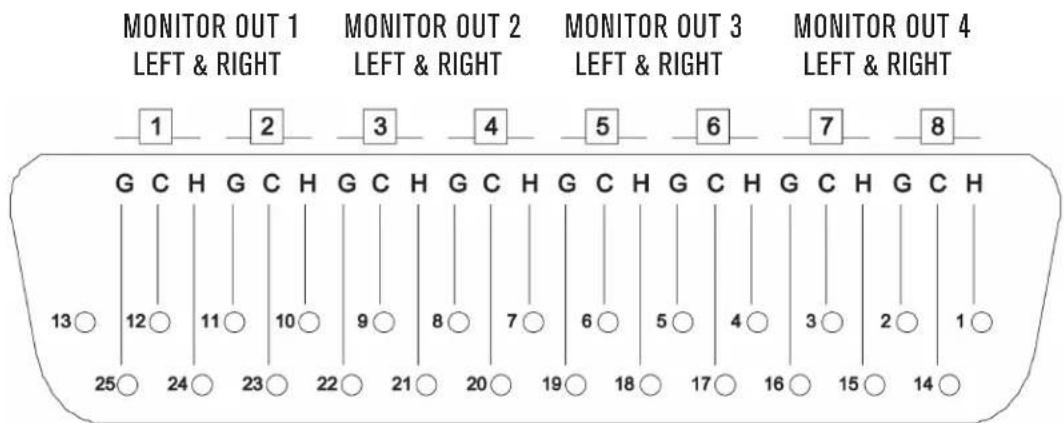
PIN OUT WIRING FOR DB25 CONNECTOR
flowchart
graph TD
    A[" Stand Alone Mastering Example"] --> B[" Tensioner "]
    B --> C[" Audio Interface "]
    C --> D[" Device Inserts to Buss A/B "]
    D --> E[" Filter 1-6: OUTBOARD GEAR INSERT 1-6"]
    E --> F[" Filter 1-6: OUTBOARD GEAR INSERT 2-2"]
    F --> G[" Filter 1-6: OUTBOARD GEAR INSERT 3-3"]
    G --> H[" Filter 1-6: OUTBOARD GEAR INSERT 4-4"]
    H --> I[" Filter 1-6: OUTBOARD GEAR INSERT 5-5"]
    I --> J[" Filter 1-6: OUTBOARD GEAR INSERT 6-6"]
    J --> K[" Filter 1-6: OUTBOARD GEAR INSERT 7-7"]
    K --> L[" Filter 1-6: OUTBOARD GEAR INSERT 8-8"]
    L --> M[" Filter 1-6: OUTBOARD GEAR INSERT 9-9"]
    M --> N[" Filter 1-6: OUTBOARD GEAR INSERT 10-10"]
    N --> O[" Filter 1-6: OUTBOARD GEAR INSERT 11-11"]
    O --> P[" Monitor OUT OF LIAISON INTO MONITOR ST INPUT 1 PRE BUSS A "]
    P --> Q[" Monitor OUT OF LIAISON INTO MONITOR ST INPUT 2 POST BUSS B "]
    Q --> R[" Monitor OUT OF LIAISON INTO MONITOR ST INPUT 3 POST BUSS B "]
    R --> S[" Monitor OUT OF LIAISON INTO MONITOR ST INPUT 4 POST BUSS B "]
    S --> T[" Monitor OUT OF LIAISON INTO MONITOR ST INPUT 5 POST BUSS B "]
    T --> U[" Monitor OUT OF LIAISON INTO MONITOR ST INPUT 6 POST BUSS B "]
    U --> V[" Monitor OUT OF LIAISON INTO MONITOR ST INPUT 7 POST BUSS B "]
    V --> W[" Monitor OUT OF LIAISON INTO MONITOR ST INPUT 8 POST BUSS B "]
    W --> X[" Monitor OUT OF LIAISON INTO MONITOR ST INPUT 9 POST BUSS B "]
    X --> Y[" Monitor OUT OF LIAISON INTO MONITOR ST INPUT 10 POST BUSS B "]
    Y --> Z[" Monitor OUT OF LIAISON INTO MONITOR ST INPUT 11 POST BUSS B "]
    Z --> AA[" Monitor OUT OF LIAISON INTO MONITOR ST INPUT 12 POST BUSS B "]
    AA --> AB[" Monitor OUT OF LIAISON INTO MONITOR ST INPUT 13 POST BUSS B "]
    AB --> AC[" Monitor OUT OF LIAISON INTO MONITOR ST INPUT 14 POST BUSS B "]
    AC --> AD[" Monitor OUT OF LIAISON INTO MONITOR ST INPUT 15 POST BUSS B "]
    AD --> AE[" Monitor OUT OF LIAISON INTO MONITOR ST INPUT 16 POST BUSS B "]
    AE --> AF[" Monitor OUT OF LIAISON INTO MONITOR ST INPUT 17 POST BUSS B "]
    AF --> AG[" Monitor OUT OF LIAISON INTO MONITOR ST INPUT 18 POST BUSS B "]
    AG --> AH[" Monitor OUT OF LIAISON INTO MONITOR ST INPUT 19 POST BUSS B "]
    AH --> AI[" Monitor OUT OF LIAISON INTO MONITOR ST INPUT 20 POST BUSS B "]
    AI --> AJ[" Monitor OUT OF LIAISON INTO MONITOR ST INPUT 21 POST BUSS B "]
    AJ --> AK[" Monitor OUT OF LIAISON INTO MONITOR ST INPUT 22 POST BUSS B "]
    AK --> AL[" Monitor OUT OF LIAISON INTO MONITOR ST INPUT 23 POST BUSS B "]
    AL --> AM[" Monitor OUT OF LIAISON INTO MONITOR ST INPUT 24 POST BUSS B "]
    AM --> AN[" Monitor OUT OF LIAISON INTO MONITOR ST INPUT 25 POST BUSS B "]
    AN --> AO[" Monitor OUT OF LIAISON INTO MONITOR ST INPUT 26 POST BUSS B "]
    AO --> AP[" Monitor OUT OF LIAISON INTO MONITOR ST INPUT 27 POST BUSS B "]
    AP --> AQ[" Monitor OUT OF LIAISON INTO MONITOR ST INPUT 28 POST BUSS B "]
    AQ --> AR[" Monitor OUT OF LIAISON INTO MONITOR ST INPUT 29 POST BUSS B "]
    AR --> AS[" Monitor OUT OF LIAISON INTO MONITOR ST INPUT 30 POST BUSS B "]
    AS --> AT[" Monitor OUT OF LIAISON INTO MONITOR ST INPUT 31 POST BUSS B "]
    AT --> AU[" Monitor OUT OF LIAISON INTO MONITOR ST INPUT 32 POST BUSS B "]
    AU --> AV[" Monitor OUT OF LIAISON INTO MONITOR ST INPUT 33 POST BUSS B "]
    AV --> AW[" Monitor OUT OF LIAISON INTO MONITOR ST INPUT 34 POST BUSS B "]
    AW --> AX[" Monitor OUT OF LIAISON INTO MONITOR ST INPUT 35 POST BUSS B "]
    AX --> AY[" Monitor OUT OF LIAISON INTO MONITOR ST INPUT 36 POST BUSS B "]
    AY --> AZ[" Monitor OUT OF LIAISON INTO MONITOR ST INPUT 37 POST BUSS B "]
    AZ --> BA[" Monitor OUT OF LIAISON INTO MONITOR ST INPUT 38 POST BUSS B "]
    BA --> BB[" Monitor OUT OF LIAISON INTO MONITOR ST INPUT 39 POST BUSS B "]
    BB --> BC[" Monitor OUT OF LIAISON INTO MONITOR ST INPUT 40 POST BUSS B "]
    BC --> BD[" Monitor OUT OF LIAISON INTO MONITOR ST INPUT 41 POST BUSS B "]
    BD --> BE[" Monitor OUT OF LIAISON INTO MONITOR ST INPUT 42 POST BUSS B "]
    BE --> BF[" Monitor OUT OF LIAISON INTO MONITOR ST INPUT 43 POST BUSS B "]
    BF --> BG[" Monitor OUT OF LIAISON INTO MONITOR ST INPUT 44 POST BUSS B "]
    BG --> BH[" Monitor OUT OF LIAISON INTO MONITOR ST INPUT 45 POST BUSS B "]
    BH --> BI[" Monitor OUT OF LIAISON INTO MONITOR ST INPUT 46 POST BUSS B "]
    BI --> BJ[" Monitor OUT OF LIAISON INTO MONITOR ST INPUT 47 POST BUSS B "]
    BJ --> BK[" Monitor OUT OF LIAISON INTO MONITOR ST INPUT 48 POST BUSS B "]
    BK --> BL[" Monitor OUT OF LIAISON INTO MONITOR ST INPUT 49 POST BUSS B "]
    BL --> BM[" Monitor OUT OF LIAISON INTO MONITOR ST INPUT 50 POST BUSS B "]
    BM --> BN[" Monitor OUT OF LIAISON INTO MONITOR ST INPUT 51 POST BUSS B "]
    BN --> BO[" Monitor OUT OF LIAISON INTO MONITOR ST INPUT 52 POST BUSS B "]
    BO --> BP[" Monitor OUT OF LIAISON INTO MONITOR ST INPUT 53 POST BUSS B "]
    BP --> BQ[" Monitor OUT OF LIAISON INTO MONITOR ST INPUT 54 POST BUSS B "]
    BQ --> BR[" Monitor OUT OF LIAISON INTO MONITOR ST INPUT 55 POST BUSS B "]
    BR --> BS[" Monitor OUT OF LIAISON INTO MONITOR ST INPUT 56 POST BUSS B "]
    BS --> BT[" Monitor OUT OF LIAISON INTO MONITOR ST INPUT 57 POST BUSS B "]
    BT --> BU[" Monitor OUT OF LIAISON INTO MONITOR ST INPUT 58 POST BUSS B "]
    BU --> BV[" Monitor OUT OF LIAISON INTO MONITOR ST INPUT 59 POST BUSS B "]
    BV --> BW[" Monitor OUT OF LIAISON INTO MONITOR ST INPUT 60 POST BUSS B "]
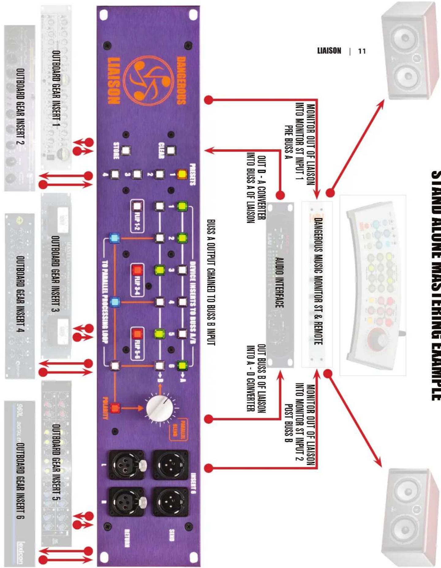
STAND ALONE MASTERING EXAMPLE
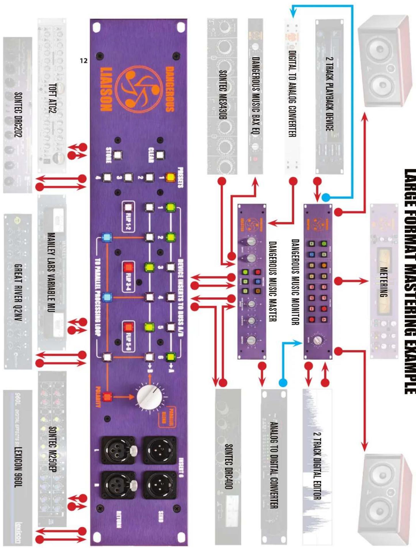
flowchart
graph TD
    A["2 TRACK PLAYBACK DEVICE"] --> B["DANGEROUS MUSIC MONITOR"]
    C["2 TRACK DIGITAL EDITOR"] --> B
    D["DIGITAL TO ANALOG CONVERTER"] --> B
    E["DANGEROUS MUSIC BAX EQ"] --> F["DANGEROUS MUSIC MASTER"]
    G["SONTEC MES430B"] --> F
    H["SONTEC DRC400"] --> F
    I["TOFT ATC2"] --> J["MANLEY LABS VARIABLE MU"]
    K["SONTEC M250EP"] --> L["GREAT RIVER Q2NV"]
    M["LEXICON 960L"] --> N["960L DIGITAL EFFECTS SY"]
    O["PHILAWITY"] --> P["TO PARALLEL PROCESSING LOOP"]
    Q["INSERT 6"] --> R["PANALLEL SLEND"]
    S["SEND"] --> T["FIRP 1-2"]
    U["RETURN"] --> V["FIRP 3-4"]
    W["PHILAWITY"] --> X["FIRP 5-8"]
    Y["PHILAWITY"] --> Z["POLARITY"]
    style A fill:#f9f,stroke:#333
    style C fill:#f9f,stroke:#333
    style D fill:#f9f,stroke:#333
    style E fill:#f9f,stroke:#333
    style G fill:#f9f,stroke:#333
    style I fill:#f9f,stroke:#333
    style K fill:#f9f,stroke:#333
    style M fill:#f9f,stroke:#333
    style Q fill:#f9f,stroke:#333
    style O fill:#f9f,stroke:#333
    style P fill:#f9f,stroke:#333
    style Q fill:#f9f,stroke:#333
    style R fill:#f9f,stroke:#333
    style S fill:#f9f,stroke:#333
    style T fill:#f9f,stroke:#333
    style U fill:#f9f,stroke:#333
    style V fill:#f9f,stroke:#333
    style W fill:#f9f,stroke:#333
    style X fill:#f9f,stroke:#333
    style Y fill:#f9f,stroke:#333
flowchart
graph TD
    A["LIASON 13"] --> B["DANGEROUS MONITOR ST (OR MONITORING DEVICE)"]
    B --> C["COMPUTER INTERFACE (DAW/CONVERTER)"]
    C --> D["OUT DAW INTO MONITOR ST"]
    C --> E["OUT PREAMP INTO BUSS A OF LIASON (TRACKING)"]
    D --> F["OUT Monitor 2 OF LIAISON INTO MONITOR ST INPUT 2"]
    E --> G["OUT BUS A OF LIAISON INTO DAW"]
    F --> H["MIC PREAMP"]
    G --> H
    H --> I["TO PARALLEL PROCESSING LOOP"]
    I --> J["POLENTY"]
    J --> K["OUTBOARD GEAR INSERT 1"]
    J --> L["OUTBOARD GEAR INSERT 2"]
    J --> M["OUTBOARD GEAR INSERT 3"]
    J --> N["OUTBOARD GEAR INSERT 4"]
    J --> O["OUTBOARD GEAR INSERT 5"]
    J --> P["OUTBOARD GEAR INSERT 6"]
    K --> Q["PURRLD BELOW INSERT 6"]
    L --> R["PURRLD BELOW INSERT 3-4"]
    M --> S["PURRLD BELOW INSERT 5-6"]
    N --> T["PURRLD BELOW INSERT 3"]
    O --> U["PURRLD BELOW INSERT 5"]
flowchart
graph TD
    A["STAND ALONE MIXING EXAMPLE"] --> B["MONITOR OUT OF LIAISON INTO MONITOR ST INPUT 1 PRE BUSS A"]
    A --> C["OUT 2-BUS LT INTO BUSS B OF LIAISON"]
    A --> D["OUT PREAMP INTO BUSS A OF LIAISON"]
    A --> E["DANGEROUS 2-BUS LT SUMMING MIXER"]
    A --> F["MONITOR OUT OF LIAISON INTO MONITOR ST INPUT 2 POST BUSS B"]
    A --> G["OUT BUSS B OF LIAISON INTO A - D CONVERTER"]
    H["DAVIDABLE DEVICE INSERTS TO BUSS A/B"] --> I["1"]
    H --> J["2"]
    H --> K["3"]
    H --> L["4"]
    H --> M["5"]
    H --> N["6"]
    O["TO PARALLEL PROCESSING LOOP"] --> P["FUP 1-2"]
    O --> Q["FUP 3-4"]
    O --> R["FUP 5-6"]
    S["Polarity"] --> T["PERALLEL PLANS"]
    U["INSET 6"] --> V["SEND"]
    W["RETURN"] --> X["1"]
    Y["14"] --> Z["OUTBOARD GEAR INSERT 1"]
    Y --> AA["OUTBOARD GEAR INSERT 2"]
    Y --> AB["OUTBOARD GEAR INSERT 3"]
    Y --> AC["OUTBOARD GEAR INSERT 4"]
    Y --> AD["OUTBOARD GEAR INSERT 5"]
    Y --> AE["960L DIGITAL GEAR INSERT 6"]
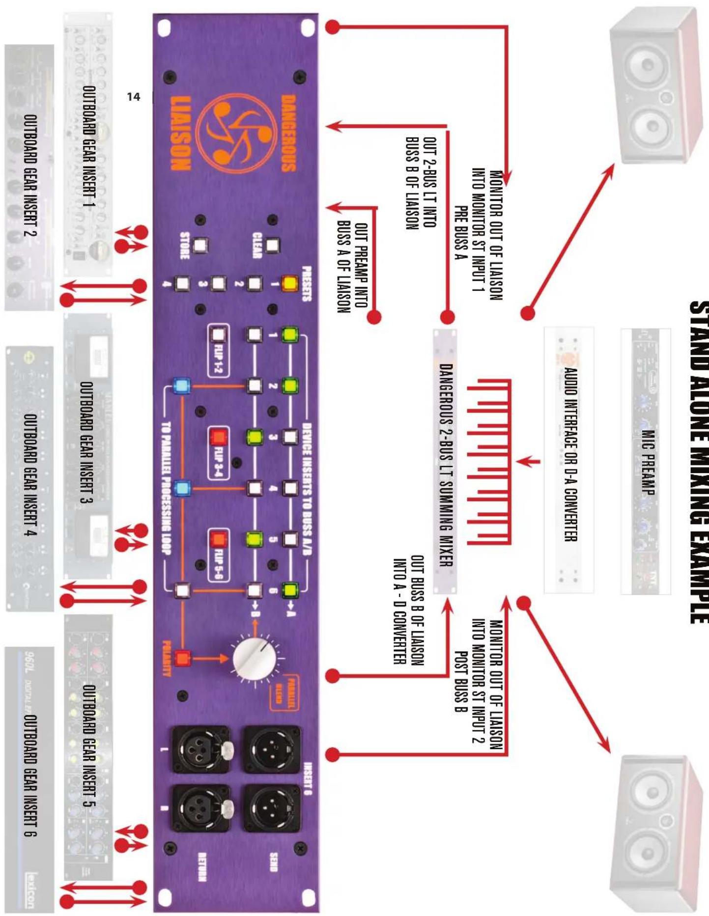
STAND ALONE MIXING EXAMPLE
flowchart
graph TD
    A["LIASON 15"] --> B["DANGEROUS MONITOR ST (OR MONITORING DEVICE)"]
    B --> C["OUT DAW INTO MONITOR ST INPUT 1"]
    C --> D["COMPUTER INTERFACE (DAW/CONVERTER)"]
    D --> E["OUT PREAMP INTO BUSS A OF LIAISON"]
    E --> F["MIC PREAMP"]
    F --> G["OUT BUISS A OF LIAISON INTO DAW"]
    G --> H["*Utilizing input 4 on the MONITOR ST, allows the post processing level to be reduced, thus matching it to the original for true A/B comparisons."]
    H --> I["TO PARALLEL PROCESSING LOOP"]
    I --> J["POLIANTY"]
    J --> K["FUP 3-4"]
    J --> L["FUP 5-6"]
    K --> M["PERALLEL BLED"]
    L --> N["INSERT 6"]
    M --> O["SEND"]
    N --> P["RETURN"]
    O --> Q["OUTBOARD GEAR INSERT 1"]
    Q --> R["OUTBOARD GEAR INSERT 2"]
    R --> S["OUTBOARD GEAR INSERT 3"]
    S --> T["OUTBOARD GEAR INSERT 4"]
    T --> U["OUTBOARD GEAR INSERT 5"]
    U --> V["OUTBOARD GEAR INSERT 6"]
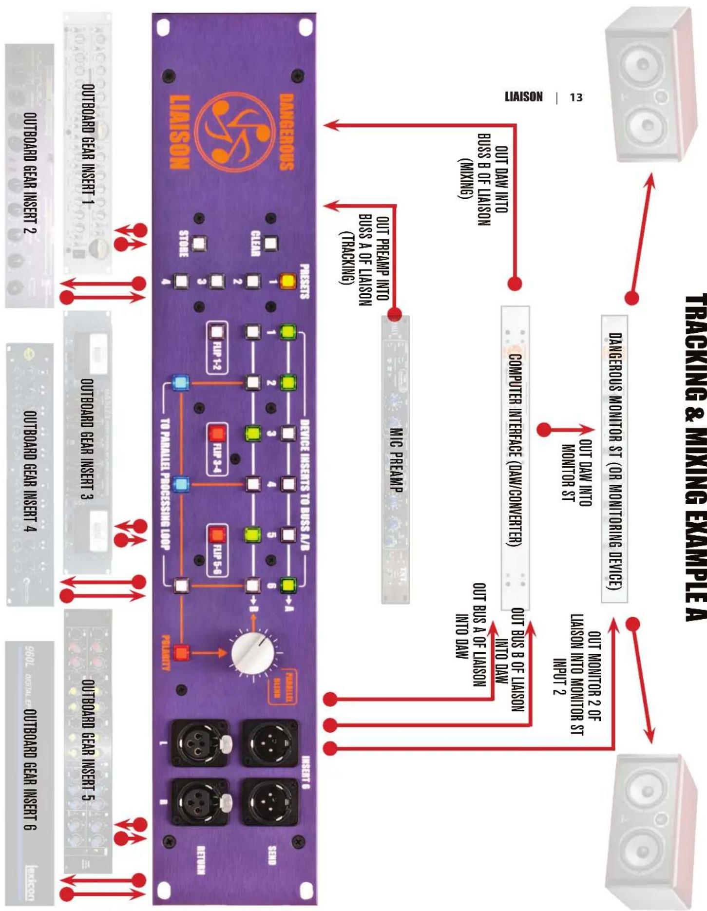
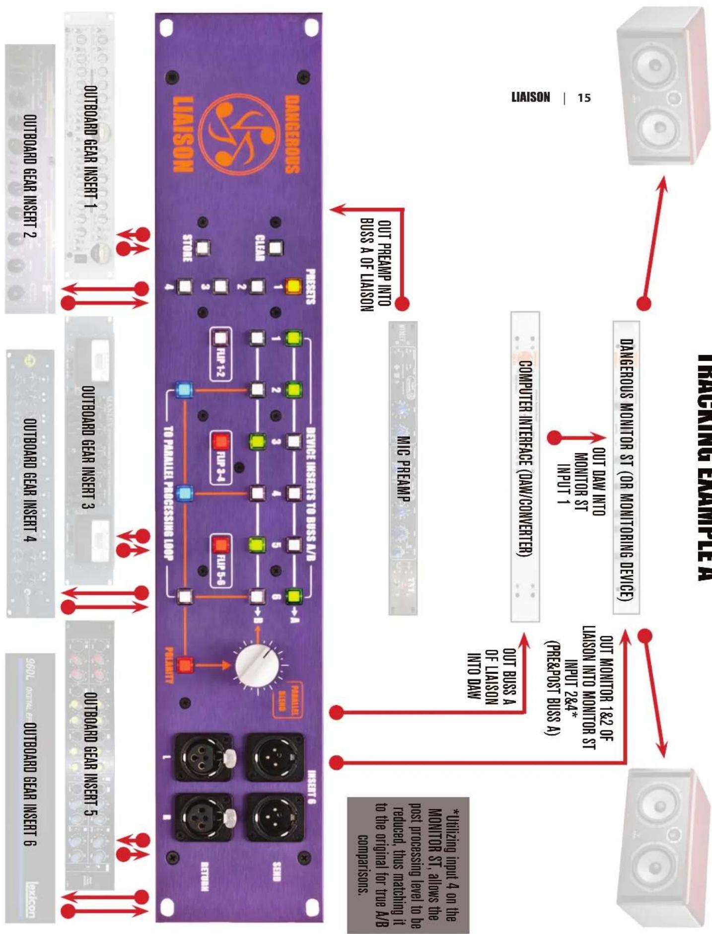
TRACKING EXAMPLE A
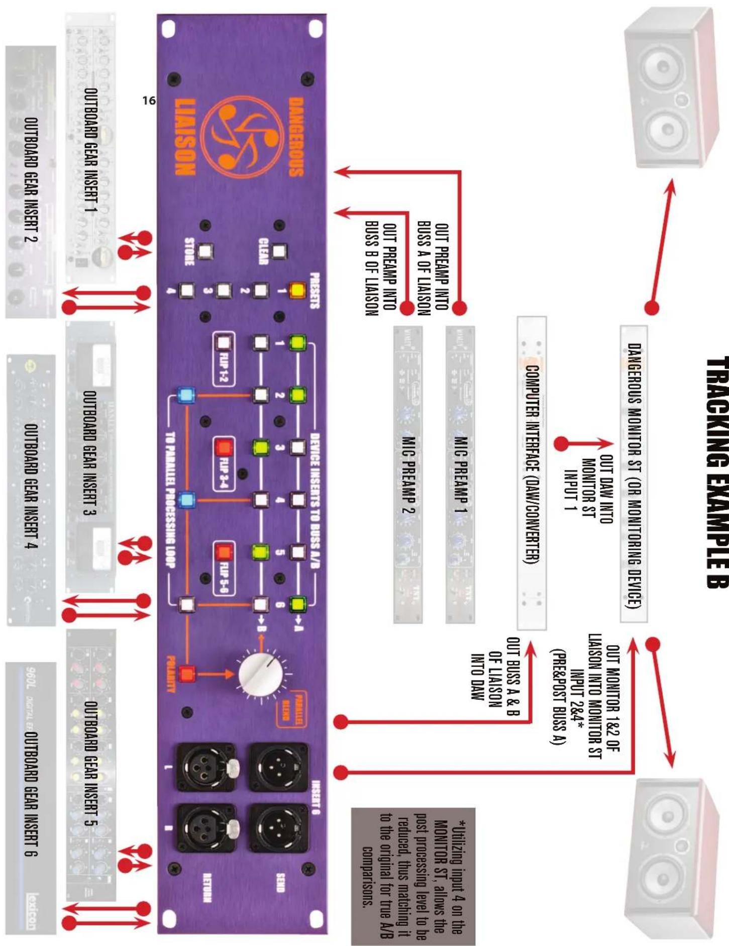
flowchart
graph TD
    A["Outboard Gear Insert 1"] --> B["DANGEROUS LIISON"]
    C["OUTBOARD Gear Insert 2"] --> B
    D["OUTBOARD Gear Insert 3"] --> B
    E["OUTBOARD Gear Insert 4"] --> B
    F["OUTBOARD Gear Insert 5"] --> B
    G["OUTBOARD Gear Insert 6"] --> B
    H["PERLARITY"] --> I["TO PARALLEL PROCESSING LOOP"]
    J["FLIP 1-2"] --> K["Device Inserts TO BUSS A/B"]
    L["FLIP 2-4"] --> K
    M["FLIP 5-6"] --> K
    N["PARALLEL BLEND"] --> O["INSERT 0"]
    P["OUT PREAMP INTO BUSS A OF LIASON"] --> Q["MIC PREAMP 1"]
    R["OUT PREAMP INTO BUSS B OF LIASON"] --> Q
    S["COMPUTER INTERFACE (DAW/CONVERTER)"] --> T["MIC PREAMP 2"]
    U["DANGEROUS MONITOR ST (OR MONITORING DEVICE)"] --> V["OUT DAW INTO MONITOR ST INPUT 1"]
    W["OUT MONITOR 1&2 OF LIASON INTO MONITOR ST INPUT 2&4* (PRE&POST BUSS A)"] --> X["OUT BUSS A & B OF LIASON INTO DAW"]
    Y["*Utilizing input 4 on the MONITOR ST, allows the post processing level to be reduced, thus matching it to the original for true A/B comparisons."] --> Z["OUTPUT AIRS"]
SPECIFICATIONS
(for monitor and parallel buss sections)
Frequency Response (Passive Section) +0, -0.1dB from 10Hz to 100kHz
Frequency Response (Active Section) +0, -0.1dB 10Hz-100kHz
Maximum level > +28dBu
Noise floor < -94.5dBu 22Hz-22kHz bandwidth
THD+N < 0.002%
IMD < 0.003%
Crosstalk rejection (Passive Section) >124dB
Crosstalk rejection (Active Section) >113dB
Input Impedance: 20K Ohms
Output Impedance: 20 Ohms
Replacement Fuses: USA 500mA fast blow for 120V
Europe 250mA fast blow for 240V
Now it's your turn to unleash the potential of the Liaison and tell us all the unusual applications you've utilized it in!
Experiment well beyond the pages of this manual. The Liaison is a still audio river that runs deep.
-The Dangerous Music Team
WARRANTY
Free 2 year extended warranty with online registration.
Standard warranty: 90 days parts and labor, subject to inspection.
Does not include damage incurred through shipping damage, abusive operation or modifications/attempted repair by unauthorized technicians.
| USA | EUROPE |
| Dangerous Music Inc. Dangerous Music Europe | |
| 231 Stevens Road Stieleichenweg 55 | |
| Edmeston, NY 13335 50999 Cologne, Germany | |
| Fon: +49 2236 393731 | |
| Email: info@dangerousmusic.com E-mail: info@dangerousmusic.de | |
Dangerous Music, Inc. reserves the right to alter the software and design of their equipment.
If after reading the manual more information for an application is needed, please contact us via email for the quickest response.
- Factory contact for RA# must occur before shipping a unit to us for service.
- Please keep the original cartons in case storage or transportation of units is required.
- Always insure shipment as these damages are not covered by the warranty.
- Thank you for actually reading the manual. Now go make some Dangerous Music!
DANGEROUS