
Ultimate 2560 - Tripod OConnor - Free user manual and instructions
Find the device manual for free Ultimate 2560 OConnor in PDF.


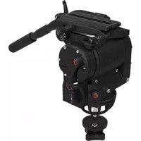
| Product Type | Fluid Head for Tripod (Cine-style) |
| Model | OConnor Ultimate 2560 |
| Weight | 7.3 kg (16.2 lb) |
| Maximum Payload | 40.72 kg (90 lb) at low center of gravity; 37.7 kg (83 lb) at 100 mm, 29.5 kg (65 lb) at 152 mm, 24.1 kg (53 lb) at 203 mm |
| Dimensions (H x W x D) | 20.3 cm x 28.7 cm x 19.1 cm (8 in x 11.3 in x 7.5 in) |
| Tilt Range | ±90° throughout entire counterbalance range |
| Pan & Tilt Drag | Continuously adjustable fluid drag, 0 to 9 scale |
| Counterbalance | Stepless, numerical display 0-99%, folding crank handle |
| Bubble Level | Illuminated with push-button (20 sec on) |
| Battery for Level | 1 x CR2032 3V coin cell |
| Mounting Base Options | Mitchell base or 150mm ball base (with tie-downs) |
| Included Accessories (Full Kit C1260-0001) | Euro style quick release plate, pan handle, pan extension handle, Mitchell tie-down, Mitchell base assembly, 150mm tie-down, 150mm base assembly |
| Operating Temperature | -40°C to +60°C (-40°F to +140°F) |
| Storage Temperature | -40°C to +60°C (-40°F to +140°F) |
| Maintenance | Regular wipe with lint-free cloth; avoid salt water; replace battery as needed; adjust lock levers if necessary |
| Safety Features | Tilt lock pin, platform release lever with safety catch, pan and tilt locks, anti-toppling warning |
| Warranty | See declaration of conformity; modifications void warranty |
Frequently Asked Questions - Ultimate 2560 OConnor
User questions about Ultimate 2560 OConnor
0 question about this device. Answer the ones you know or ask your own.
Ask a new question about this device
Download the instructions for your Tripod in PDF format for free! Find your manual Ultimate 2560 - OConnor and take your electronic device back in hand. On this page are published all the documents necessary for the use of your device. Ultimate 2560 by OConnor.
USER MANUAL Ultimate 2560 OConnor
natural_image
Black industrial machine with control panel and display, no visible text or symbolsPart No. C1260-0001
C1260-0002
Copyright © 2015
All rights reserved.
Original Instructions: English
All rights reserved throughout the world. No part of this document may be stored in a retrieval system, transmitted, copied or reproduced in any way, including, but not limited to, photocopy, photograph, magnetic or other record without the prior agreement and permission in writing of the Vitec Group Plc.
Disclaimer
The information contained in this manual is believed to be correct at the time of printing. Vitec Videocom Ltd reserves the right to make changes to the information or specifications without obligation to notify any person of such revision or changes. Changes will be incorporated in new versions of the publication.
We are making every effort to ensure that our manuals are updated on a regular basis to reflect changes to product specifications and features. Should this manual not contain information on the core functionality of your product, please let us know. You may be able to access the latest revision of this manual from our website.
Vitec Videocom Ltd reserves the right to make changes to product design and functionality without notification.
Trademarks
OConnor® is a registered trademark of the Vitec Group Plc.
All product trademarks and registered trademarks are the property of The Vitec Group Plc.
All other trademarks and registered trademarks are the property of their respective companies.
Published by:
Vitec Videocom Ltd
Supports Technical Publications Department
Western Way, Bury St Edmunds
Suffolk IP33 3TB
United Kingdom
Email: technical.publications@vitecgroup.com
Contents
Safety....2
About this User Guide 3
Components 4
Front View....4
Rear View 5
Box Contents C1260 - 0001 6
Optional Accessories 7
Installation 9
Installing the Head and Payload 8
Mounting the head 8
Levelling the Head 8
Lock Pin 9
Mounting the Camera 10
Fitting the Pan Handle 11
Balancing the Camera 11
Fore / Aft Balance 12
Payload Weight and C of G Height Adjustment 14
Numeric Display 14
Adjusting the Centre of Gravity (C of G) 15
Operation 16
Operating the Pan and Tilt Locks 16
Pan and Tilt Fluid Drag 17
Maintenance 19
Battery Replacement 18
Adjust Lock Levers 19
Cleaning 20
Technical Specification 21
General Notices 22
Safety
Important information on the safe installation and operation of this product. Read this information before operating the product. For your personal safety, read these instructions. Do not operate the product if you do not understand how to use it safely. Save these instructions for future reference.
Warning Symbols Used in These Instructions
Safety cautions are included in these instructions. These safety instructions must be followed to avoid possible personal injury and avoid possible damage to the product.

WARNING!
Where there is a risk of personal injury or injury to others, comments appear supported by the warning triangle symbol. Where there is a risk of damage to the product, associated equipment, process or surroundings, comments appear supported by the word 'CAUTION'.
Health and Safety

WARNING! Risk of personal injury or injury to others. All personnel must be fully trained and adhere to correct manual handling techniques and Health & Safety regulations. It is the responsibility of the local organisation to enforce safe working practices at all times.
Mounting, Installation and Operation

WARNING! Risk of finger entrapment. Do not place fingers between the platform and body of the fluid head.

WARNING! Avoid trapping fingers when collapsing and extending tripod legs.

WARNING! DO NOT fit the head to a tripod that cannot support the combined mass of the head and its full payload.

WARNING! Toppling hazard. Do not leave unattended. Keep out of reach of children.

WARNING! The product must always be secured.

CAUTION! Always lock the vertical and horizontal brakes when the camera is mounted but not in use or when levelling the fluid head on the tripod.

CAUTION! Hold the camera securely when mounting or dismounting from the fluid head and when making adjustments to the tripod height or footprint.

CAUTION! Always hold the pan bar when making adjustments to the counterbalance or camera position. Do not use the pan bar to lift or move the tripod and fluid head.

CAUTION! Only attach camera accessories to the pan bar. Do not attach heavy items to the pan bar.

CAUTION! Always remove the camera before transporting.

WARNING! Before fitting or adjusting the camera or payload the tilt lock pin must be engaged. See "Installation" on page 9.
Safety / About This Guide
Maintenance

WARNING! The fitting of non-approved parts and or accessories, the carrying out of non-approved alterations or servicing can be dangerous and could affect the safety of the product. It may also invalidate the terms and conditions of the product warranty.

CAUTION! When replacing the battery, use only the same or an equivalent type of battery recommended for use with the product.
About this User Guide
This guide describes the installation, configuration and operation of the OConnor 2560 fluid head.
The 2560 features OConnor's step-less counterbalance system as well as ultra-smooth pan and tilt fluid drag designed for cine style shooting.
A collapsible counterbalance crank handle and numerical readout make counterbalancing the payload easy. The platform and brake arrangements mean that all of the controls are on the camera operator's side of the head (left side) for an improved operation experience.
Additionally the platform has a marking scale and four rosette handle mountings. The platform release lever has a one touch finger and thumb actuated safety release catch, while still requiring conscious effort for safety.
OConnor's fluid drag system allows an extremely quick pan movement from one position to another, recovering instantly without any spring back.
Variants
Two variants of the 2560 are available.
Basic Kit C1260 - 0002:
Supplied as a basic head with no accessories.
natural_image
Technical line drawing of a mechanical assembly with gears and shafts (no text or symbols)
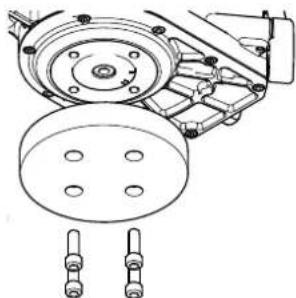
The C1260-0002 is supplied with a protective plastic base, secured with 4 x Allen bolts, which must be removed and swapped for a 150mm spherical and tie down or Mitchell and tie down before use.
Full Kit C1260 - 0001:
Supplied as a full kit, see Box Contents C1260 - 0001 on page 6.
Components
Front View

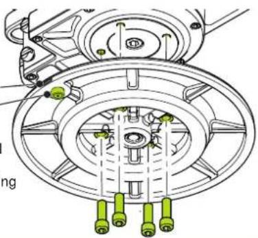
Attach either Mitchell Base (shown) or 150mm ball base using 4 x Hex screws
natural_image
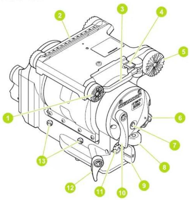
Technical line drawing of a mechanical assembly with no visible text or symbols1 Front end handle / accessory mounting rosette
2 Slide plate scale
3 Platform release lever
4 Platform release lever safety catch
5 Rear large pan handle / accessory mounting rosette
6 Tilt centre lock
7 Bubble illumination button
8 Bubble level
9 Pan fluid drag adjustment knob
10 Tilt lock lever
11 Pan fluid drag display
12 Pan lock lever
13 Front box mounting screws
Components
Rear View
Euro Style Quick Release Plate
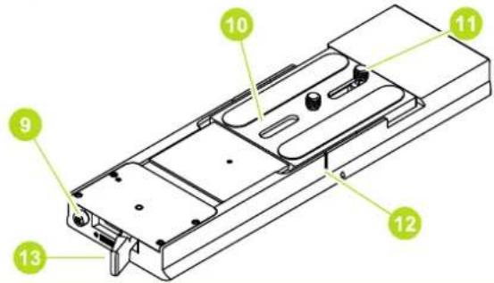
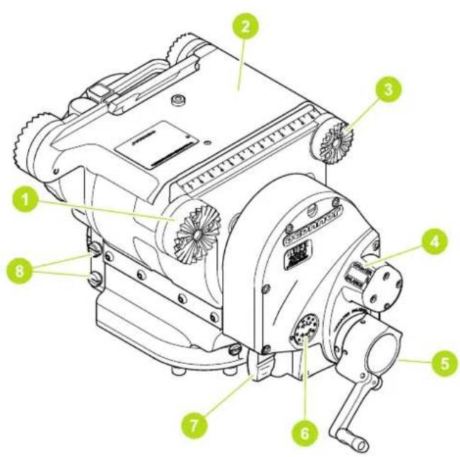
1 Rear large pan handle / accessory mounting rosette
2 Platform
3 Front small pan handle / accessory mounting rosette
4 Counterbalance numerical display
5 Folding counter balance adjustment crank
6 Tilt fluid drag display
7 Tilt fluid drag adjustment knob
8 Eyepiece leveller mounting screws
9 Camera plate clamp release lever
10 Camera mounting plate
11 Camera fixing screws
12 Slide plate marker
13 Camera plate clamp lever
Components
Box Contents C1260 - 0001
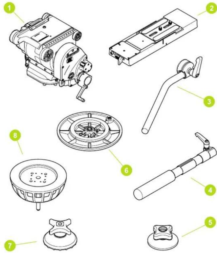
Item Description
1 2560 head
2 Euro style quick release plate
3 Pan handle
4 Pan extension handle
5 Mitchell tie down
6 Mitchell base assembly
7 150mm tie down
8 150mm base assembly
*Variant C1260-0002 consists of head only.
Components
Optional Accessories
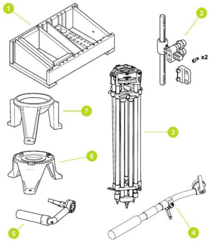
Item Description Part No.
| 1 Assistants box CSE-MFB100 | |
| 2 Eye piece leveller C1504-1000 | |
| 3 Tripods | |
| Cine HD Mitchell C1221-0001 | |
| Cine HD 150mm ball base C1221-0003 | |
| Cine HD Baby Mitchell C1221-0002 | |
| Cine HD Baby 150mm ball base C1221-0004 | |
| 4 Pan handle 08409 | |
| 5 Front handle C1260-1010 | |
| 6 High hat Mitchell C1250-0001 | |
| 7 High hat 150mm C1250-0002 | |
| OConner plate (Not shown) 08283 | |
| Arri plate dovetail (Not shown) 2575 - 210 | |
| Arri platform plate (Not shown) C2575 - 0240 | |
| Large pan handle (Not shown) 2575 - 107 |
Installation
Mounting the head
The 2560 is installed onto standard tripods using either the Mitchell base and tie down or the 150mm ball base and tie down as required.

WARNING! Do Not fit a head to a tripod that cannot support the combined mass of the head and its full payload.

WARNING! If required use a mid-level or floor spreader to ensure that the tripod legs are spread sufficiently; this ensures that the C of G remains within the footprint of the tripod.

Refer to the tripod instructions supplied with the tripod for correct fitting procedure.
Levelling the Head
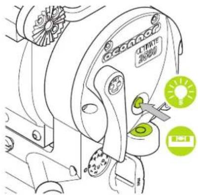
After securely mounting the head on to the tripod, center the bubble level to set the level.
If necessary, in poor light conditions:
-
Press the button illumination bubble (the light will remain on for 20 seconds).
-
Press the button again within 20 seconds to turn the light off.
Ball Base
Loosen the bowl clamp. Move the fluid head to center the level bubble. Tighten the bowl clamp and re-check the level.
Mitchell Base
Levelling is achieved by adjusting the legs on the tripod until the level bubble is centred.
Installation

Ensure the tilt lock is engaged and camera and all accessories are fitted.
Lift the tilt lock lever, it will rest in a neutral position. (Do not try to force all the way back)
Rotate the camera plate through the horizontal plane until an audible click is heard as the lock pin engages.

Mounting the Camera
The camera is attached to the head by means of a side loading platform mechanism.

WARNING! Before fitting or adjusting the camera or payload the tilt lock pin must be engaged. See "Installation" on page 9.
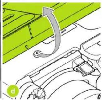
- Release side loading platform if fitted.
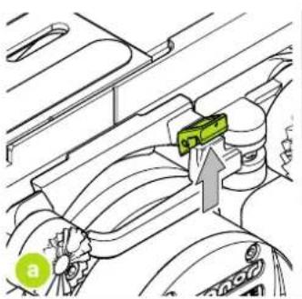
natural_image
Technical diagram of a mechanical component with a green component and directional arrow (no text or symbols)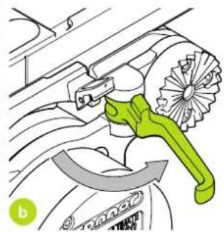
natural_image
Diagram of a car's exhaust pipe with a green tool inserted, showing mechanical components and airflow direction (no text or symbols)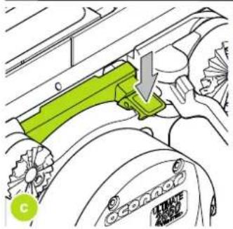
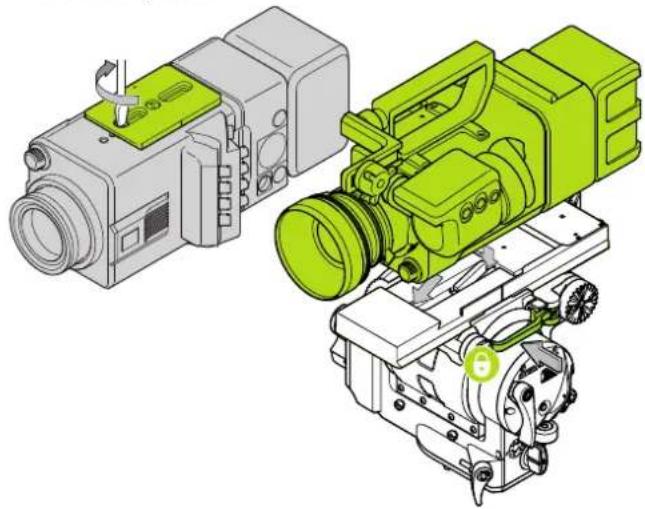
- Attach the mounting plate securely to the bottom of the camera in the desired position.
natural_image
Technical illustration of two green and gray industrial camera modules (no text or symbols)- Engage the tilt lock pin.
- Release the safety catch and pull out the platform release lever.
- Slide the camera mounting plate on to the platform towards the right side of the head until an audible "click" is heard. When the platform hook engages the camera mounting plate, the plate is captive, but not locked.
- Engage the base plate with the mounting plate. Slide the camera and plate to the required position and lock by closing the platform release lever.
Installation
Fitting the Pan Handle
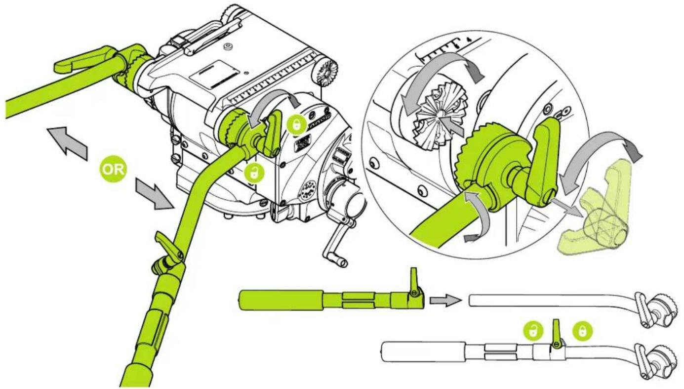
Pan Handle / accessory mounting rosettes are located at the front and rear of the head, on both the left and right sides.
Installation
Fore/Aft Balance
Ensure that the head is level before balancing. The camera and payload should be fitted on the head, so that the load is balanced. This can be achieved by moving the camera forwards (Fore) or backwards (Aft) on the cradle.

WARNING! When balancing the payload, it is important to be aware of the potential danger that an unbalanced payload will fall away suddenly. Maintain a firm hold on the payload until the balance is set correctly.

WARNING! The payload balancing procedure requires the assistance of another person.

CAUTION! The camera, handles and all accessories must be fitted in their operational position before balancing the head. Any equipment fitted or adjusted later can unbalance the head.

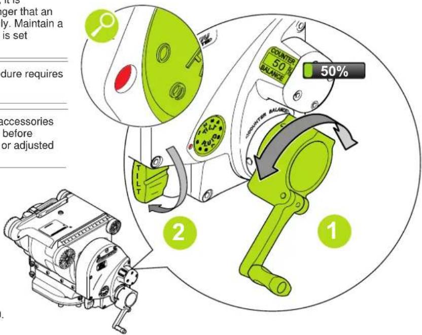
Turn the counterbalance crank to set the counterbalance to 50%.

Set the tilt fluid drag adjustment knob to 0.

Depending on the payload weight, it may be necessary to increase or decrease this setting to enable the payload to be correctly balanced fore and aft.
Installation

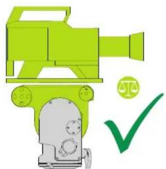
Hold and steady the camera, then disengage the tilt lock and observe how it moves and where it stops.
natural_image
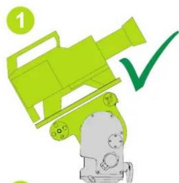
Illustration of a green video camera with a checkmark and scale symbol (no text or labels)If the camera cradle stops in a horizontal position (camera pointing directly forward), the balance is correct.
natural_image
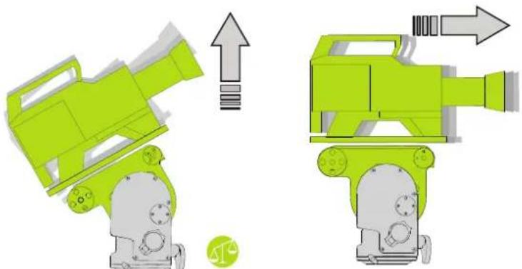
Two green toy camera models with directional arrows indicating motion or assembly (no text or symbols)If the camera tilts backwards (points upward), then the camera must be moved towards the front of the head (fore).

Reposition the camera as required on the head and secure in position. The horizontal balance is correct when the camera cradle comes to rest in a horizontal position.
natural_image
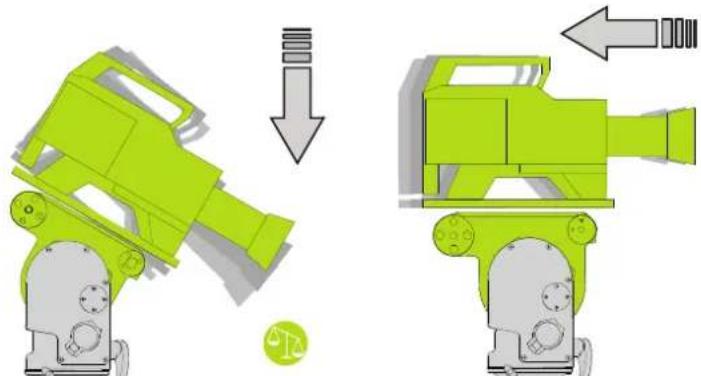
Two green 3D-rendered mechanical devices with internal components, shown before and after assembly (no text or symbols)If the camera tilts forward (points downwards), then the camera must be moved towards the rear of the head (aft).

If there is insufficient movement in the sliding plate to achieve balance, remove camera and plate from the head, reattach the mounting plate to the camera in the required position, remount the camera and plate, repeat the balancing procedure.
Installation
Payload Weight and C of G Height Adjustment

WARNING! For safe and reliable operation the head and all mounted equipment must be correctly balanced.

If the correct numerical balance setting of the payload is known, tilt the platform to the horizontal position and turn the counterbalance crank until the display shows the correct setting
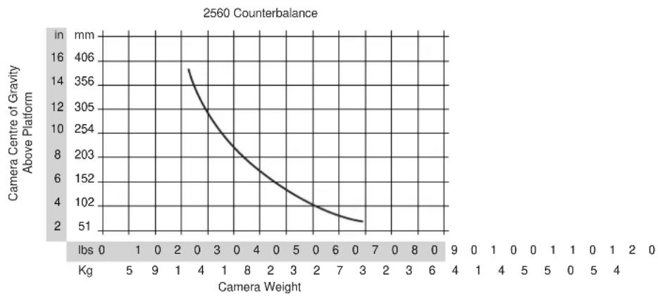
Maximum and minimum payloads that can be balanced are dependent on the weight of the camera and accessories and on the centre of gravity (C of G) height. The graph below shows the range of loads and C of G heights that can be maintained in balance. The counterbalance can be adjusted all the way to zero (no counterbalance) and the head can still be tilted ±90^ .
Numeric Display
The numeric display indicates the setting of the counterbalance mechanism on a scale of 0-99%. Adjust the counterbalance crank clockwise to increase the counterbalance setting and counter clockwise to reduce it.
The display has a three color coded band offering advance warning of cranking to the end limits.

CAUTION! When cranking into the red zone be careful to stop before reaching either 0 or 99% as damage could occur.
line
| Camera Weight | Camera Centre of Gravity Above Platform (in mm) | | ------------- | --------------------------------------------- | | 0 | 140 | | 4 | 356 | | 8 | 203 | | 2 | 102 | | 7 | 51 |Adjusting the Counter Balance

CAUTION! Risk of damage to equipment. Be prepared to prevent the camera from falling away suddenly
natural_image
Illustration of a green toy car with a checkmark and circular badge, no text or symbols presentTilt the camera approx. 45° upward and release it. If the camera stays in the same position when released, the camera is correctly balanced with the C of G on the tilt axis.
natural_image
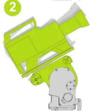
3D rendered diagram of a green and gray mechanical device with no visible text or symbolsIf the camera continues to move towards the horizontal after releasing the camera cradle, reduce the counterbalance.

natural_image
Diagram of a mechanical device with green handle and black clip, enclosed in a circular frame (no text or symbols)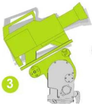
natural_image
Illustration of a green and gray toy device with no visible text or symbols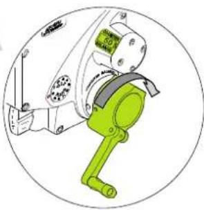
natural_image
Diagram of a green manual hand tool interacting with a mechanical device, enclosed in a circular frame (no text or symbols)If the camera keeps falling back towards the vertical position when released, increase the counterbalance.
Tilt the camera over the TDC, it should remain stationary at any angle.
If the camera angle falls or rises, repeat the alignment procedure until balance is achieved.
After adjusting the counterbalance, it may be necessary to check that the fore and aft balance remains satisfactory. Readjust the position of the camera horizontally on the camera plate as required.
After balancing, exercise the head through both axes to confirm that it operates smoothly.

The sliding plate is marked and the platform has graduations. Make a note of the "balanced" position to simplify rebalancing this particular payload.
Operation
Operating the Pan and Tilt Locks
The pan and tilt friction locks are operated by levers on the left of the head. The locks should be applied whenever the camera/head is left unattended.
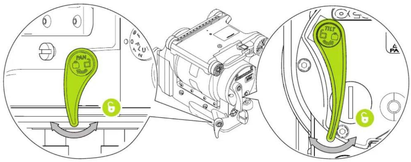

After prolonged use, if the lock does not fully engage at the end of the lock lever travel, refer to Adjust Lock Levers on page 19. The levers are designed so they can be released simultaneously with one hand.
Operation
Pan and Tilt Fluid Drag
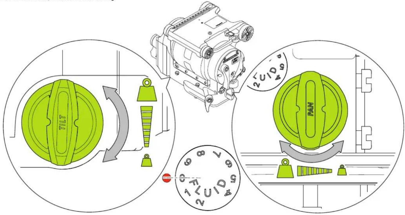
The pan drag adjustment knob is located on the lower right rear of the head, and the tilt drag adjustment knob on the lower left of the head. Both controls are continuously adjustable from 0 to 9. To increase drag, turn the knob clockwise, towards a higher setting. To decrease drag, turn the knob counter-clockwise, towards a lower setting.
Maintenance
Battery Replacement
The battery illuminates the bubble level. It should be replaced whenever the illumination becomes inadequate.
- Use a coin or flat blade screwdriver to unscrew the battery cover.
- Carefully pull the battery out of its compartment.
- Fit a replacement CR 2032 3v battery in the compartment, ensuring that the positive side (+) of the battery faces outermost.
- Replace the battery cover and tighten using a coin or flat blade screwdriver.
- Press the bubble level illumination button and verify that the bubble level is lit for approximately 20 seconds.

Maintenance
Adjust Lock Levers
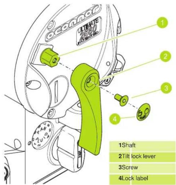
If the pan and/or tilt friction locks do not fully engage at the end of the lock lever travel, adjust the lever position as follows:
-
Rotate the lock lever to the "locked" position.
-
The lock lever is attached by means of a screw. Carefully peel off the lock label to expose the screw. Using a 2.5 mm Allen key remove the screw.
-
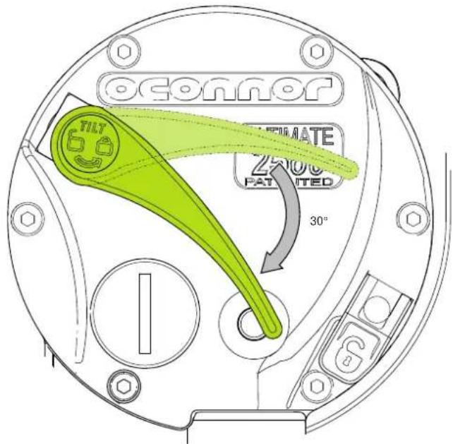
Pull the lock lever off the hexagonal shaft, rotate it approx. 30^ away from the "locked" end of travel, and reinstall it.
- Tighten the screw. Reapply the lock label.
Maintenance
Cleaning
We encourage regular cleaning of the product. During normal use the only cleaning required should be a regular wipe over with a lint-free cloth.
Cover the head when not in use. Dirt accumulated during storage or periods of non-use may be removed with a vacuum cleaner.

CAUTION! Salt water will damage the head! If product comes into contact with salt water, immediately rinse with distilled water and dry with compressed moving air.
Storing the Head
- When shooting is finished the head should be stored in the case.
- Store in a dry area.
- You may leave the counterbalance and drag settings at the end of a shoot.
- For long term storage, we advise that the counterbalance is adjusted towards 100% .

CAUTION! Never force the counterbalance when resistance is felt near 0 or 100%.
Technical Specification
Physical Data

Height
20.3 cm (8 in.)

Depth
19.1 cm (7.5 in)

*Maximum payload
40.72 kg (90 lb)

Storage temp.
-40°C to +60°C
(-40°F to +140°F)

Bubble level
Illuminated

Width
28.7 cm (11.3 in.)

Weight
7.3 kg (16.2 lb)

Tilt
±90° throughout entire
counterbalance
range, zero to max.

Operating Temp.
-40°C to +60°C
(-40°F to +140°F)

Battery
Type: 1 x CR 2032 3v
\*Capacity:
@100mm (4 in) 37.7 kg (83 lb.)
@152mm (6 in) 29.5 kg (65 lb.)
@ 203mm (8 in) 24.1 kg (53 lb.)
General Notices
Declaration of Conformity

Vitec Videocom Limited declares that this product has been manufactured in accordance with BS EN ISO 9001:2008 and is in compliance with the essential requirements and other relevant provisions of the Machinery Directive 2006/42/EC. A copy of the Declaration of Conformity is available upon request.
Environmental considerations
European Union Waste of Electrical and Electronic Equipment (WEEE) Directive (2002/96/EC)
This symbol marked on the product or its packaging indicates that this product must not be disposed of with general household waste. In some countries or European Community regions separate collection systems have been set up to handle the recycling of electrical and electronic waste products. By ensuring this product is disposed of correctly, you will help prevent potentially negative consequences for the environment and human health. The recycling of materials helps conserve natural resources.
Visit our website for information on how to safely dispose of this product and its packaging.
In countries outside the EU:
Dispose of this product at a collection point for the recycling of electrical and electronic equipment according to your local government regulations.
Disposal of waste batteries
Any batteries included with this product must not be treated as household waste. By ensuring these batteries are disposed of correctly, you will help prevent potentially negative consequences for the environment and human health, and help conserve natural resources.
Read 'Battery Replacement' section in this manual for instructions on how to remove the battery from the product safely. Hand the battery over to the applicable collection point for recycling waste batteries.
Publication part No. C1260-4980/1
oconnor

OConnor™ A Vitec Group brand

www.ocon.com

- Copyright © 2015
- Disclaimer
- Trademarks
- Published by:
- Contents
- Safety
- Warning Symbols Used in These Instructions
- WARNING!
- Health and Safety
- Mounting, Installation and Operation
- Safety / About This Guide
- Maintenance
- About this User Guide
- Variants
- Components
- Item Description
- Installation
- Mounting the head
- Levelling the Head
- Ball Base
- Mitchell Base
- Mounting the Camera
- Fitting the Pan Handle
- Fore/Aft Balance
- Payload Weight and C of G Height Adjustment
- Numeric Display
- Adjusting the Counter Balance
- Operation
- Operating the Pan and Tilt Locks
- Pan and Tilt Fluid Drag
- Battery Replacement
- Adjust Lock Levers
- Cleaning
- Storing the Head
- Technical Specification
- Physical Data
- \*Capacity:
- General Notices
- Declaration of Conformity
- Environmental considerations
- European Union Waste of Electrical and Electronic Equipment (WEEE) Directive (2002/96/EC)
- In countries outside the EU:
- Disposal of waste batteries
Brand : OConnor
Model : Ultimate 2560
Category : Tripod