
C1234-0004 - Tripod OConnor - Free user manual and instructions
Find the device manual for free C1234-0004 OConnor in PDF.

| Brand | OConnor |
| Model | C1234-0004 |
| Product Type | Pan and Tilt Head (for Tripod) |
| Payload Capacity | 0 to 87 lb (39.5 kg) at C of G height 8" (20.3 cm) |
| Tilt Range | ±90° |
| Pan Range | 360° |
| Height | 8.4 in (21.3 cm) |
| Width | 12.4 in (31.5 cm) |
| Depth | 8.6 in (21.8 cm) |
| Weight | 22.9 lb (10.4 kg) |
| Operating Temperature Range | -40°F to +140°F (-40°C to +60°C) |
| Base Interface | Mitchell base or 150mm Ball Base |
| Counterbalance System | Stepless sinusoidal mechanism with numeric display (0-99%) |
| Pan Fluid Drag | Continuously adjustable 0 to 9 |
| Tilt Fluid Drag | Continuously adjustable 0 to 9 |
| Pan and Tilt Locks | Friction locks on each axis, left side levers |
| Tilt Lock Pin | Horizontal lock with red/green indicator |
| Bubble Level | Illuminated, activation button, 20-second timer |
| Handle Mounts | Four rosette mountings (front/rear, left/right) |
| Camera Mounting Platform | Side-loading, interchangeable plates: Euro, OConnor, Panavision, ARRI dovetail |
| Battery (Bubble Level) | CR 2032 3V, replaceable |
| Maintenance | Periodic cleaning with lint-free cloth; no solvent-based cleaners |
| Safety Features | Counterbalance crank clutch, tilt lock pin, warning labels |
Frequently Asked Questions - C1234-0004 OConnor
User questions about C1234-0004 OConnor
0 question about this device. Answer the ones you know or ask your own.
Ask a new question about this device
Download the instructions for your Tripod in PDF format for free! Find your manual C1234-0004 - OConnor and take your electronic device back in hand. On this page are published all the documents necessary for the use of your device. C1234-0004 by OConnor.
USER MANUAL C1234-0004 OConnor
natural_image
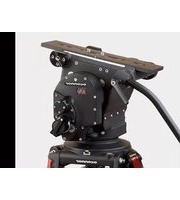
Close-up of a black oconnor camera with visible control knobs and a green indicator light (no text or symbols on the device itself)Operator's Guide
Part No. C1234-4980
OConnor 2575D Pan and Tilt Head Operator's Guide, Part No. C1234-4980
Copyright © Vitec Group plc 2008
All rights reserved throughout the world. No part of this document may be stored in a retrieval system, transmitted, copied or reproduced in any way including, but not limited to, photocopy, photograph, magnetic or other record without the prior agreement and permission in writing of Vitec Group plc.
OConnor ^® is a registered trademark of Vitec Group plc.
Preface
Thank you and congratulations on the purchase your new 2575D from OConnor.
We want you to get the most from your new 2575D, and therefore encourage you to read this operator's guide to familiarize yourself with its many features, some of which may be new to you. It also covers essential health and safety information and a section on maintenance that will ensure you keep your new product in perfect condition.
Please register your purchase online at www.ocon.com.
Features and benefits of your new 2575D
The 2575D head is the flagship of OConnor's Ultimate range of fluid heads and features OConnor's stepless counterbalance system as well as ultra-smooth pan and tilt fluid drag designed for cine style shooting.
A collapsible counterbalance crank handle and numerical readout make counterbalancing the payload easy. The new platform has all the controls on the camera operator's side of the head (left side) and features a platform scale on both sides and four rosette handle mountings. The platform release lever has a one touch finger actuated safety release catch—while still requiring conscious effort.
OConnor's fluid drag system allows an extremely quick pan movement from one position to another, recovering instantly without any spring back.
You can set up easily in low light conditions using the illuminated level bubble.
Once again, thank you for choosing the 2575D. We are confident it will give you many years of reliable performance.
Safety - Read This First
Warning Symbols in this Operators Guide

Where there is a risk of personal injury, injury to others, or damage to the pan and tilt head or associated equipment, appropriate comments appear, highlighted by the word WARNING! and this warning triangle symbol.
Technical Data
Payload Capacity: .... Minimum: zero lb (no load) Maximum: 87 lb (39.5 kg) at C of G height of 8" (20.3 cm). See counterbalance chart
Tilt Range: ±90^ throughout entire counterbalance range, zero to maximum
Pan Range: 360°
Height: 8.4 in (21.3 cm)
Width: 12.4 in (31.5 cm)
Depth: 8.6 in (21.8 cm)
Weight: 22.9 lb (10.4 kg)
Operating Temperature Range: .. -40°F to +140°F (-40°C to +60°C)
Dolly/tripod fixing: .... Mitchell baseor 150mm Ball Base
Further Information
For further information or advice regarding this pan and tilt head, please contact
OConnor Engineering at:
Camera Dynamics
OCONNOR ENGINEERING
2701 N. Ontario St.
Burbank, CA 91504
Tel: 818-847-8666
Fax: 818-847-1205
E-mail: info@ocon.com
Or visit our website www.ocon.com and use the contact form.
Contents
Preface 2
Features and benefits of your new 2575D....2
Safety - Read This First 3
Technical Data 4
Further Information 5
Contents 6
Introduction....7
Counterbalance 8
Numeric Display 8
Ultra Smooth Fluid Drag....9
Pan And Tilt Locks 9
Tilt Lock Pin 9
Illuminated Bubble Level 9
Handle Mounting 9
Camera Mounting Platform 9
Bases 10
Operation 11
Installing The Head....11
Handles 11
Mounting A Camera 11
Stability....12
Balancing The Head....13
Fore And Aft Balance 13
Payload Weight And C of G Height Adjustment 15
Locking The Platform 15
Pan And Tilt Locks 16
Pan And Tilt Fluid Drag. 16
Storing the head....16
Servicing 17
General....17
Routine Maintenance 17
Cleaning....17
Battery Replacement 18
Adjusting The Lock Levers....18
Introduction
2575D Pan and Tilt Head (front left view)
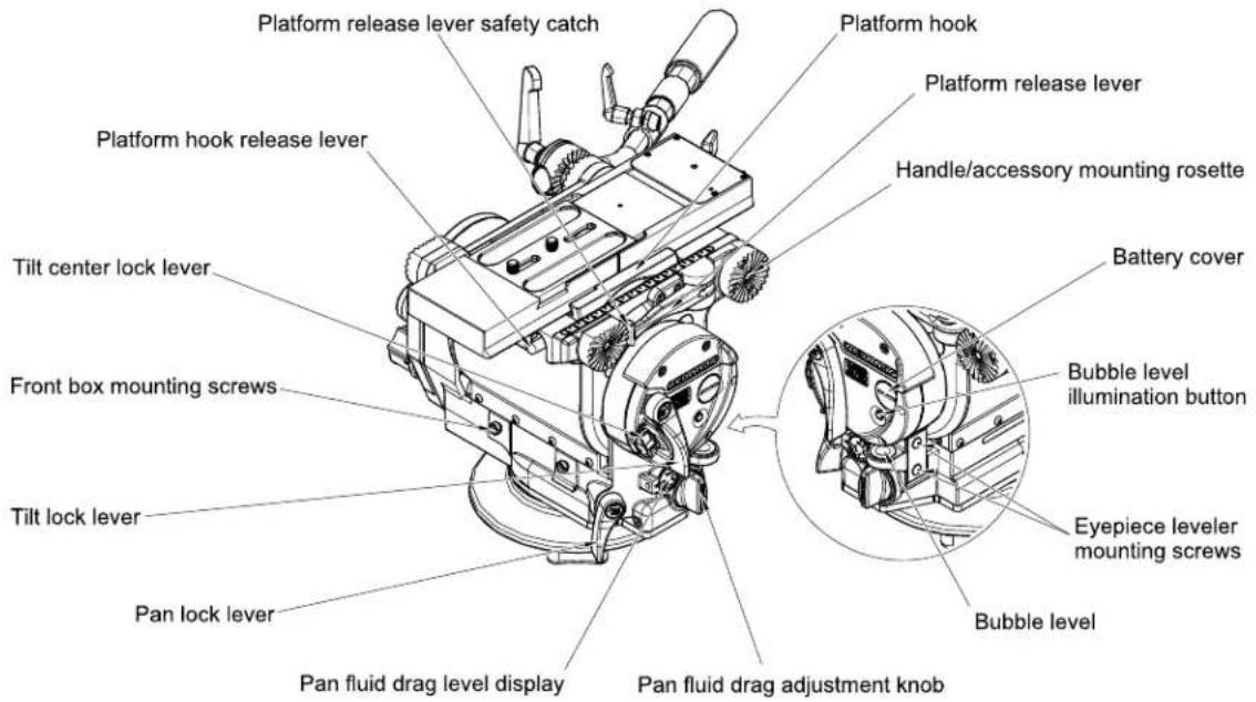
2575D Pan and Tilt Head (rear right view)

The 2575D pan and tilt head embodies a patented sinusoidal counterbalance mechanism for true and accurate balance; stepless drag assemblies for ultrasmooth pan and tilt motions; and an adjustable camera mounting plate.
Counterbalance
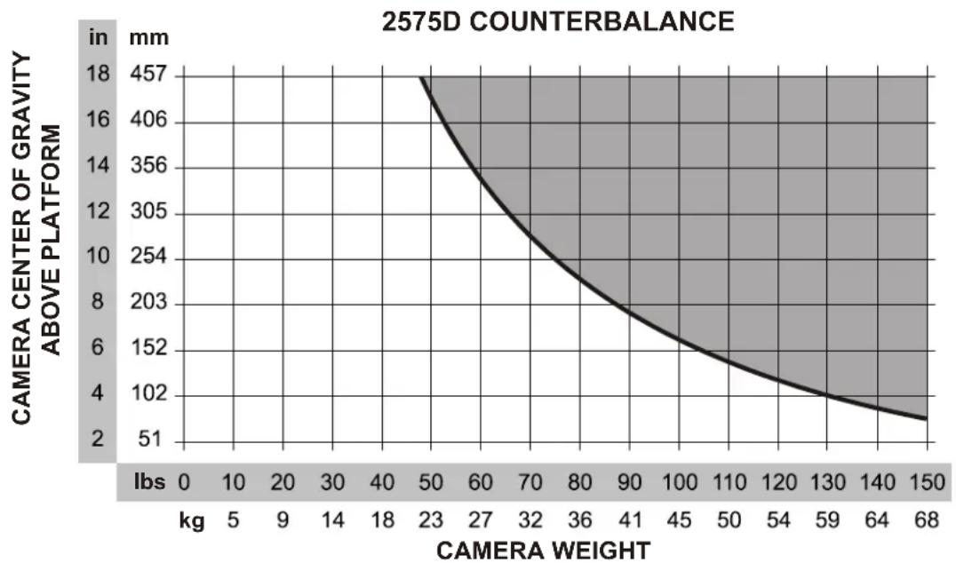
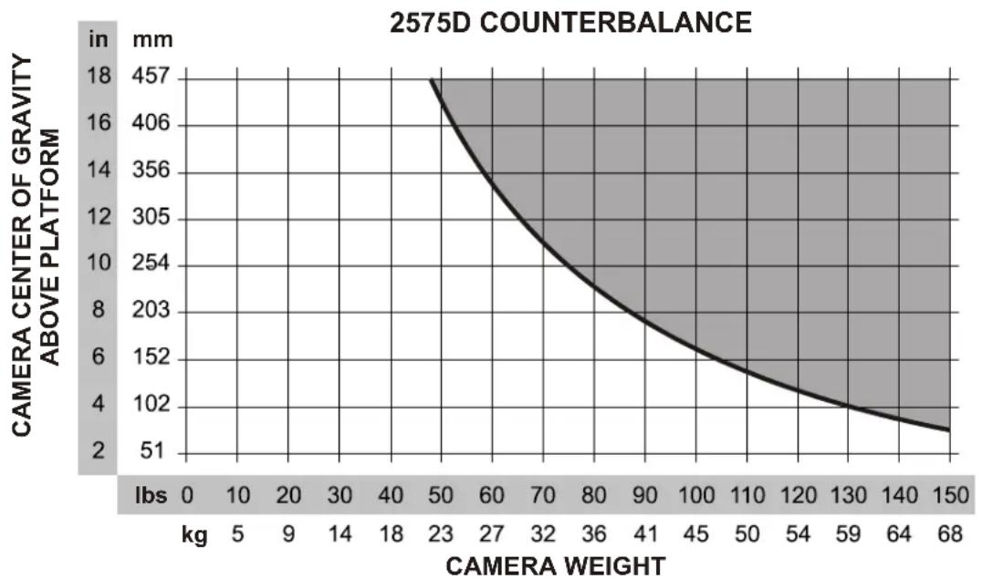
The balance mechanism is adjusted by the counterbalance crank on the lower right of the head. The knob has a folding handle which incorporates a clutch to prevent inadvertent damage to the balance mechanism by over cranking. Maximum and minimum payloads that can be balanced are dependent on the weight of the camera and accessories and on the center of gravity (C of G) height. The graph below shows the range of loads and C of G heights that can be maintained in balance. The counterbalance can be adjusted all the way to zero (no counterbalance) and the head can still be tilted ±90^ .
line
| CAMERA WEIGHT | CAMERA CENTER OF GRAVITY ABOVE PLATFORM (in mm) | | ------------- | ----------------------------------------------- | | 0 | 457 | | 5 | 406 | | 10 | 356 | | 15 | 305 | | 20 | 254 | | 25 | 203 | | 30 | 152 | | 35 | 102 | | 40 | 8 | | 45 | 6 | | 50 | 4 | | 55 | 2 | | 60 | 1 | | 65 | 0.5 | | 70 | 0.25 | | 75 | 0.125 | | 80 | 0.0625 | | 85 | 0.03125 | | 90 | 0.015625 | | 95 | 0.0078125 | | 100 | 0.00390625 | | 105 | 0.001953125 | | 110 | 0.0009765625 | | 115 | 0.00048828125 | | 120 | 0.000244140625 | | 125 | 0.0001220703125 | | 130 | 0.00006103515625 | | 135 | 0.000030517578125 | | 140 | 0.0000152587890625 | | 145 | 0.00000762939453125 | | 150 | 0.000003814697265625 |Numeric Display
The numeric display indicates the setting of the counterbalance mechanism on a scale of 0-99%. Adjust the counterbalance crank clockwise to increase the counterbalance setting and counter clockwise to reduce it. The display has a three color coded band offering advance warning of cranking to the end limits. Green represents the normal operating range, yellow indicates adjustment within 20-10% from the end limit and red indicates adjustment within 10-0% from the end limit. When cranking into the red zone be careful to stop before reaching either “0%” or “99%”.

WARNING!
Do NOT attempt to adjust the counterbalance crank below 0% or above 99% as damage could occur
Ultra Smooth Fluid Drag
Both the pan and tilt mechanisms incorporate OConnor's ultra smooth fluid drag to ensure smooth movement. The pan drag adjustment knob is located on the lower left rear of the head with its indicator wheel on the left side of the head, and the tilt drag adjustment knob on the lower rear-right side of the head with its indicator wheel on the right side end cover. Both controls are continuously adjustable from 0 to 9.
Pan And Tilt Locks
Friction locks on each axis allow the head to be locked at any desired position. The pan and tilt lock levers are on the left-side of the head with the tilt lock above the pan lock for easy and seamless operation.
Tilt Lock Pin
The tilt lock pin on the left side of the head is used to lock the platform in a horizontal position. The lock pin is actuated by a flip lever with red (locked) and green (unlocked) label indicators.
Illuminated Bubble Level
The bubble level on the left side of the head can be illuminated by pressing the bubble level illumination button. The light will go out after approximately 20 seconds.
Handle Mounting
Handle mounting rosettes are located at the front and rear of the head, on both the left and right sides. A telescoping extension handle is supplied and is attached using the handle clamp, with angular adjustment available on the rosette serrations. Additional handles, including a front handle, Randal handle and accessories can also be installed.
Camera Mounting Platform
The camera is attached to the head by means of a side loading platform mechanism. The mechanism is released by sliding the red clamp lock button to the left while pulling out the platform release lever in a counterclockwise direction. Once the release lever has been rotated about 90°, the red hook
release lever in front of the platform can be pushed down and the platform removed from the head.
The platform plate options for the 2575D head are a follows:
- Euro style quick release with 120mm camera mounting plate & screws
- OConnor plate with screws
• Panavision dovetail plate - ARRI dovetail plate, 12" long
- ARRI dovetail plate, 24" long
Bases
The 2575D head can be fitted with either a Mitchell base and tiedown or a 150mm ball base and tiedown. Bases are secured by four 14 -20 socket head cap screws requiring a 3/16" hex drive wrench.
Operation
Installing The Head
The 2575D head may be installed onto standard tripods using either the Mitchell base and tiedown or the 150mm ball base and tiedown as required.

WARNING!
Do NOT fit the head to a tripod that cannot support the combined mass of the head and its full payload.
After securely mounting the head on the tripod, use the bubble level to set it level. If necessary, press the bubble level illumination button to view the bubble level in poor light conditions.
Handles
Install the handles on the rosette handle mounts and adjust the position before tightening the clamps. Adjust the length of the telescoping handle as desired.
Mounting A Camera

WARNING!
Do not rely on the tilt lock when changing the payload. Always tilt the platform horizontal and engage the tilt lock pin by placing it in the red (engaged) position. The tilt pin will drop into the platform.
- Ensure that the weight and C of G height of the total payload is within the range for which the head is designed
- If you are installing the head on a crane, pedestal or dolly, lock the crane, pedestal or dolly before installing the camera.
To mount the camera:
- Attach the mounting plate to the bottom of the camera/lens.
- Engage the tilt lock pin.
- Release the safety catch and pull out the platform release lever.
- Slide the camera mounting plate on to the platform towards the right side of the head until a loud "click" is heard. Once the platform hook
engages the camera mounting plate, the camera is captive, but not locked.
Alternatively, press down and hold the red platform hook release lever on the front left hand side of the head, and position the camera mounting plate on top of the head. Release the red hook release lever until the platform hook automatically secures the camera mounting plate.
- Engage the platform release lever by rotating it towards the platform until the red safety catch engages.
- Install the remainder of the payload (lens, zoom and focus controls, viewfinder, prompter etc).
Stability

WARNING!
When mounting the head on a tripod, it is possible to set the tripod legs so that the center of gravity of the tilted payload falls outside the footprint of the tripod, leading to instability.
Use the mid-level or floor spreader to ensure that the tripod legs are spread sufficiently so that the center of gravity of the tilted payload remains within the footprint of the tripod.
Balancing The Head
Make sure that the head is level before balancing. Check the bubble level to verify that the head itself is level and make sure that the platform is also level.
NOTE: It is important that the handle(s) and all camera accessories (lens, zoom and focus controls, viewfinder, prompter etc.) are fitted in their operational position before balancing the head. Any equipment fitted or adjusted later can unbalance the head.
Balancing the 2575D head achieves two objectives. First, when a head is correctly balanced the operator will need a minimum amount of effort to move the camera. Second, once balanced, the head and its payload can be set to any tilt position and the head will maintain this position with 'hands off'.
The chart below shows the range of load and C of G heights that can be maintained in balance. The area under the balance curve (colored white) corresponds to load/C of G combinations that can be balanced over the full tilt range of ±90^ . The area above the balance curve (shaded grey) corresponds to load/C of G combinations that exceed the capacity of the head.
line
| CAMERA WEIGHT | CAMERA CENTER OF GRAVITY ABOVE PLATFORM (in mm) | | ------------- | ----------------------------------------------- | | 0 | 457 | | 5 | 406 | | 10 | 356 | | 15 | 305 | | 20 | 254 | | 25 | 203 | | 30 | 152 | | 35 | 102 | | 40 | 8 | | 45 | 6 | | 50 | 4 | | 55 | 2 | | 60 | 1 | | 65 | 0.5 | | 70 | 0.25 | | 75 | 0.125 | | 80 | 0.0625 | | 85 | 0.03125 | | 90 | 0.015625 | | 95 | 0.0078125 | | 100 | 0.00390625 | | 105 | 0.001953125 | | 110 | 0.0009765625 | | 115 | 0.00048828125 | | 120 | 0.000244140625 | | 125 | 0.0001220703125 | | 130 | 0.00006103515625 | | 135 | 0.000030517578125 | | 140 | 0.0000152587890625 | | 145 | 0.00000762939453125 | | 150 | 0.000003814697265625 |Fore And Aft Balance
- When positioning the payload, it is important to be aware of the potential danger that an unbalanced payload will fall away suddenly. Always be prepared for this by maintaining a firm hold on the payload until the balance is set correctly.
- Make sure that the camera and all accessories are installed in their operating positions.
- Before disengaging the tilt lock pin, turn the Counterbalance crank to set the counterbalance to 50%. Depending on the payload weight, it
may be necessary to increase or decrease this setting to enable the payload to be correctly balanced fore and aft.
-
Make sure that the tilt lock pin is engaged.
-
Set the tilt fluid drag adjustment knob to 0.

WARNING! Be prepared to prevent the head falling away suddenly. In the event of the head falling away violently, increase the counterbalance setting using the counterbalance crank.
- Holding the handle to steady the platform, disengage the tilt lock pin.
- Tilt the platform forwards and backwards and determine if camera package is front or back heavy.
- If it is not in balance, re-engage the tilt lock pin.
a. Release the safety catch and disengage the platform release lever. With the help of an assistant, carefully slide the camera payload and plate forwards or backwards until the payload is balanced fore and aft.
9. The horizontal balance is correct when no perceptible tilting force can be felt on the handle with the platform level and with the tilt lock pin disengaged.
10. Fully engage the platform release lever to secure the payload in position. The red safety button should engage the platform release lever.
11. If there is insufficient movement in the sliding plate to achieve balance, determine which direction the mounting plate needs to be moved to achieve correct balance. Remove the payload from the head, reattach the mounting plate to the camera in the required position, remount the load and repeat the horizontal balancing procedure.
12. The sliding plate is marked and the platform has graduations. Make a note of the “balanced” position to simplify rebalancing this particular payload.
Payload Weight And C of G Height Adjustment
The fore and aft balance must be set before adjusting the payload weight and C of G height adjustment.
NOTE: If the correct numerical balance setting of the payload is known, tilt the platform to the horizontal position and turn the counterbalance crank until the numerical display shows the correct setting.
- Using the handle, tilt the platform downwards and upwards. When correctly balanced, there should be no perceptible tilting force on the handle at any angle of tilt and the head should remain in any tilt position to which it is set.
- If the head tends to fall away when the platform is tilted, the counterbalance will need to be increased. If the head tends to spring back when the platform is tilted the counterbalance will need to be decreased.
- Set the platform level, unfold the counterbalance crank handle and turn it clockwise to increase or counter-clockwise to decrease the counterbalance setting as required.
- Using the handle, tilt the platform upward and downward to recheck the balance. Readjust counterbalance until balance is achieved.
- Make a note of the final numeric counterbalance setting to simplify rebalancing this particular payload.
- When the payload weight and C of G height adjustment is complete, check that the fore and aft balance is still correct. Re-adjust the position of the sliding plate if necessary.
- After balancing, exercise the head through the full range of pan and tilt to confirm that it operates smoothly.
Locking The Platform
The tilt lock pin mechanism is operated by a flip lever on the left-hand side of the head. To engage the pin, hold the platform in the horizontal position and flip the lever over from the green position to the red position. If necessary, use the handle to rock the head slightly to achieve the fully locked position. The pin and flip lever will snap towards the platform as the pin engages.
To release the tilt lock pin, flip the lever over from the red position to the green position. If the platform is not balanced this may require force. If so, make sure that the tilt lock lever is rotated clockwise to hold the platform in place.
Pan And Tilt Locks
The pan and tilt friction locks are operated by levers on the left of the head. The locks should be applied whenever the camera/head is left unattended.
Rotate the pan lock lever clockwise (toward the front of the head) to engage the lock.
Rotate the tilt lock lever counter clockwise (upwards) to engage the lock.
If the lock does not fully engage at the end of the lock lever travel, refer to "Adjusting The Lock Levers" in the Servicing section below.
Pan And Tilt Fluid Drag
Both the pan and tilt mechanisms incorporate the OConnor ultra smooth fluid drag system to ensure smooth movement. The pan drag adjustment knob is located on the lower right rear of the head, and the tilt drag adjustment knob on the lower left of the head. Both controls are continuously adjustable from 0 to 9. To increase drag, turn the knob clockwise, towards a higher setting. To decrease drag, turn the knob counter-clockwise, towards a lower setting.
Storing the head
When shooting is finished and the head is to be stored, head settings (i.e. counterbalance and fluid drag) should be left unchanged. This will reduce wear on the head's mechanisms and save time on the next shoot.
Servicing
General
The 2575D pan and tilt head is robustly made to high engineering standards and little attention is required to maintain serviceability except for regular cleaning.
For service beyond the maintenance items described below, contact the OConnor headquarters or your local OConnor representative. Contact information is provided at the end of this document.
Routine Maintenance
Replace the battery whenever the bubble level illumination is inadequate.
During normal use, check the following:
Check the effectiveness of the pan and tilt locks. Reset as necessary – see below.
Check the operation of the illumination of the bubble level. Replace the battery if necessary – see below.
No other routine maintenance is required.
Cleaning
During normal operation the only cleaning required is a periodic wipe down with a lint-free cloth. Any dirt that accumulates during storage or periods of non-use may be removed with a semi-stiff brush. Particular attention should be paid to the dovetail faces of the camera mounting area.
NOTE: Use only detergent-based cleaners. DO NOT use solvent-based or oil-based cleaners, abrasives or wire brushes to remove accumulations of dirt as these will damage the protective surfaces.
Use out-of-doors under adverse conditions may require special attention and the head should be covered when not in use. Salt spray should be washed off using fresh water at the earliest opportunity. Sand and dirt act as an abrasive and should be removed using a semi-stiff brush or a vacuum cleaner.
Battery Replacement
The battery illuminates the bubble level. It should be replaced whenever the illumination becomes inadequate.

-
If required, rotate the tilt lock lever to assess the battery cover.
-
Use a coin or flat blade screwdriver to unscrew the battery cover.
-
Carefully pull the battery out of its compartment with its ribbon.
-
Fit a replacement CR 2032 3v battery in the compartment, ensuring that the positive side (+) of the battery faces outermost and the ribbon is correctly positioned.
-
Replace the battery cover and tighten using a coin or flat blade screwdriver.
-
Press the bubble level illumination button and verify that the bubble level is lit for approximately 20 seconds.
Adjusting The Lock Levers
If the pan and/or tilt friction locks do not fully engage at the end of the lock lever travel, adjust the lever position as follows:
-
Rotate the lock lever to the "locked" end of travel.
-
Use a 3/32" hex key to loosen the set screw in the lock lever.
-
Pull the lock lever off the hexagonal shaft, rotate it away from the "locked" end of travel by one flat on the shaft and reinstall it.
-
Tighten the set screw.
oconnor
Headquarters
2701 N. Ontario St.
Burbank, CA 91504
USA
Tel: +1 818 847 8666
Fax: +1 818 847 1205
USA
709 Executive Blvd
Valley Cottage, NY 10989
USA
Tel: +1 845 268 0100
YongAn Dongli A No. 8
Jianwai Ave., Chaoyang District
Beijing, China 100022
Tel: +86 10 8528 8748
Fax: +86 10 8528 8749
France
natural_image
Professional video camera on a tripod with Earth in the foreground (no visible text or symbols)Germany
-Gebäude 16-
Planiger Straße 34
55543 Bad Kreuznach
Germany
Tel: +49 671 483 43 - 30
Fax: +49 671 483 43 - 50
Erfurter Straße 16
85386 Eching
Germany
Tel: +49 89 321 58 200
Fax: +49 89 321 58 227
Japan
P.A. Bldg. 5F
3-12-6 Aobadai
Meguro-ku Tokyo 153-0042
Japan
Tel: +81 3 5456 4155
Fax: +81 3 5456 4156
Singapore
6 New Industrial Road
02-02 Hoe Huat Industrial Building
Singapore 536199
Tel: +65 6297 5776
Fax: +65 6297 5778
UK
William Vinten Building
Western Way
Bury St. Edmunds
Suffolk IP33 3TB
UK
Tel: +44 1284 752121
Fax: +44 1284 750560
Sales Fax: +44 1284 757929
Specifications are subject to change without notice

- Preface
- Features and benefits of your new 2575D
- Safety - Read This First
- Technical Data
- Further Information
- Contents
- Preface 2
- Safety - Read This First 3
- Technical Data 4
- Further Information 5
- Contents 6
- Introduction....7
- Operation 11
- Servicing 17
- Introduction
- Counterbalance
- Numeric Display
- WARNING!
- Ultra Smooth Fluid Drag
- Pan And Tilt Locks
- Tilt Lock Pin
- Illuminated Bubble Level
- Handle Mounting
- Camera Mounting Platform
- Bases
- Operation
- Installing The Head
- Handles
- Mounting A Camera
- To mount the camera:
- Stability
- Balancing The Head
- Fore And Aft Balance
- WARNING! Be prepared to prevent the head falling away suddenly. In the event of the head falling away violently, increase the counterbalance setting using the counterbalance crank.
- Payload Weight And C of G Height Adjustment
- Locking The Platform
- Pan And Tilt Fluid Drag
- Storing the head
- Servicing
- General
- Routine Maintenance
- Cleaning
- Battery Replacement
- Adjusting The Lock Levers
- oconnor
- Headquarters
- USA
- France
- Germany
- Japan
- Singapore
- 02-02 Hoe Huat Industrial Building
- UK
Brand : OConnor
Model : C1234-0004
Category : Tripod