
XD642P-DP - Network Equipment Adder - Free user manual and instructions
Find the device manual for free XD642P-DP Adder in PDF.


| Product Type | KVM Extender (Transmitter and Receiver pair) |
| Model | Adder XD642P-DP (Dual Head) |
| Dimensions (Transmitter & Receiver) | 186 mm x 152 mm x 40 mm (7.32 in x 5.98 in x 1.57 in) |
| Weight (Transmitter) | 1.29 kg (2.84 lbs) |
| Weight (Receiver) | 1.24 kg (2.73 lbs) |
| Power Supply | External 12V DC, 1.5A; 100-240V AC 47-63Hz input |
| Power Consumption | Nominal 10W, Peak 12W |
| Video Support | Dual DisplayPort up to 4K (4096x2160) @60Hz (fiber); up to 2K (2048x1080) @60Hz (CATx dual head) |
| Link Types | CATx (up to 100m with CAT6) or Fiber (up to 4km single-mode) |
| USB Support | USB 2.0: 2x type B (transmitter), 3x type A HID + 1x transparent Hi-Speed (receiver) |
| Audio | Analog stereo line in/out, mono microphone, stereo speakers; digital audio over DisplayPort |
| Serial Port | RS232 via RJ12 Remote port, up to 115200 baud |
| Operating Temperature | 0°C to +40°C |
| Storage Temperature | -10°C to +50°C |
| Humidity (Operating/Storage) | 0-80% RH (non-condensing) |
| Maximum Altitude | 2000 m |
| Thermal Dissipation | 41.94 BTU/hr |
| Enclosure Material | Robust metal construction |
| Supplied Items | Transmitter, Receiver, 2x Power adapters with locking connector and country-specific cords, DisplayPort cable (2m), USB cable (2m A to B), Audio cable (3m), Quick setup guide, Safety documents, Rubber feet |
| Optional Extras | Replacement power adapter (PSU-IEC-12VDC-1.5A), Serial cable (VSC50), SFP modules (SFP-MM-LC-10G, SFP-SM-LC-10G) |
| Safety | Class 1 Laser product; suitable for Information Technology Rooms per NEC Article 645 and NFPA 75; do not use unearthed sockets; keep ventilation clear; max ambient 40°C |
| Maintenance | No user-serviceable parts; firmware upgrade via USB memory stick (FAT32); reset via recessed button |
Frequently Asked Questions - XD642P-DP Adder
User questions about XD642P-DP Adder
0 question about this device. Answer the ones you know or ask your own.
Ask a new question about this device
Download the instructions for your Network Equipment in PDF format for free! Find your manual XD642P-DP - Adder and take your electronic device back in hand. On this page are published all the documents necessary for the use of your device. XD642P-DP by Adder.
USER MANUAL XD642P-DP Adder
ADDERLink™ XD641 and XD642
User Guide
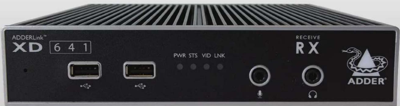

(1) 本报告标题、内容与格式
Experts in Connectivity Solutions

Extender Solutions
Contents
Introduction
Welcome....2
AdderLink XD641 features....3
AdderLink XD642 features....4
Technical specifications 5
Supplied items 6
Optional extras....7
Installation
Locations 8
Connections 8
Transmitter video link(s)....9
Transmitter audio links 9
Transmitter USB links....10
Transmitter Remote port....10
Transmitter power connection .... 11
Linking....12
CATx link....12
Fiber optic link....13
Receiver video display(s) 14
EDID management....14
Receiver audio devices....14
Receiver USB devices....15
Receiver Remote port 15
Receiver power connection....16
Configuration
Accessing the Dashboard....17
Choosing the dual head mode (XD642 models only)....17
Resetting a module....18
Upgrading Firmware....18
Operation
Indicators 19
Further information
Getting assistance 20
Appendix I - Remote port pin-out....21
Index

Introduction

WELCOME
Thank you for choosing the ADDERLink® XD641 (single head) or XD642 (dual head) extender modules. Using either fiber optic or CATx links, these compact modules allow you to extend KVM connections over long distances from a host computer (see Transmission distances when using fiber on the right).
The high-grade screening employed within the metal cased enclosures, particularly when combined with the immunity from interference of the fiber optic links.
AdderLink XD extender modules provide support for:
• High quality single- or dual- digital video (up to 4K 4096 x 2160 @60Hz),
• USB keyboard and mouse plus two other USB devices (up to USB 2.0),
• An RS232 serial device at speeds up to 115200 baud,
- Mono microphone,
- Stereo speakers,
• Line-level audio in/out connections.

The ADDERLink extender modules are totally transparent in operation, leaving you free to use your computer as though you're still sitting next to it.
Transmission distances when using fiber
The choice of fiber used with the ADDERLink XD modules has a considerable effect on the distance over which operation can take place. Using multi-mode fiber you can achieve distances up to 400m (1,312 feet); whereas, by using single-mode fiber (and accompanying SFP modules), the achievable maximum distance is increased to 4km (2.5 miles):
| Distance | Fiber type | Fiber color code | SFP module |
| 70m | OM1 (TIA-492AAAA) | Orange | SFP-MM-LC-10G |
| 150m | OM2 (TIA-492AAAB) | Orange | SFP-MM-LC-10G |
| 380m | OM3 (TIA-492AAAC) | Aqua | SFP-MM-LC-10G |
| 400m | OM4 (TIA-492AAAC) | Aqua | SFP-MM-LC-10G |
| 4km | OS1 (TIA-492C000) | Yellow | SFP-SM-LC-10G |
| OS2 (TIA-492E000) | Yellow | SFP-SM-LC-10G |
Fiber optic link
(up to 4km
OR
CATx link
(CAT5e up to 50m)
(CAT6 up to 100m)
ADDERLink XD
Receiver module
Single or dual (XD642 models) DisplayPort ^® video displays
Four USB devices
One RS232 serial device
Stereo speakers plus microphone
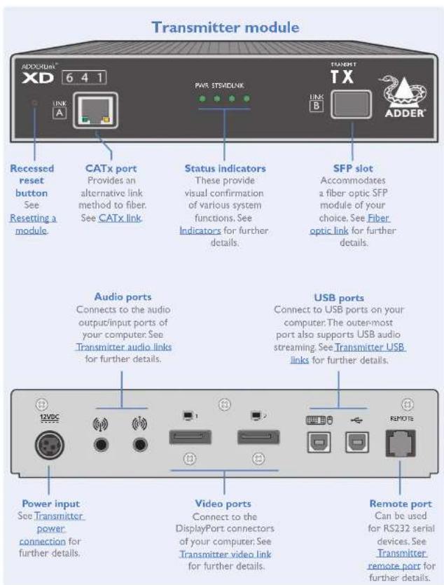
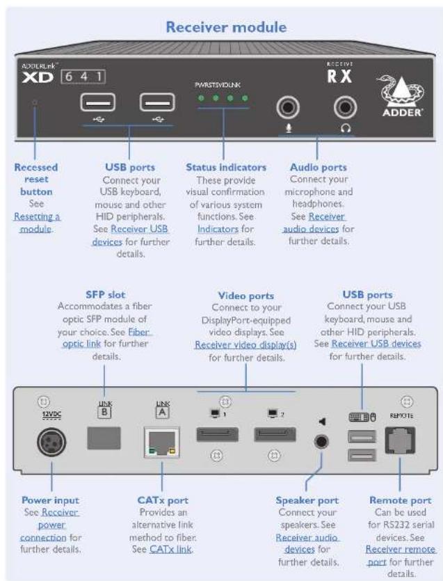
ADDERLINK XD641 FEATURES
The transmitter and receiver modules are contained within slimline metal casings that measure just 186 × 152 × 40 mm.

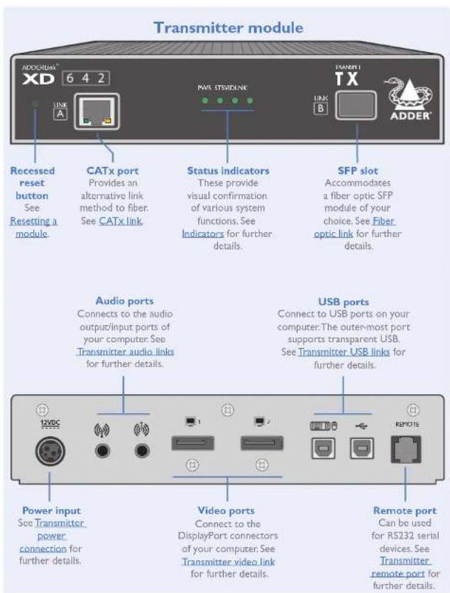
ADDERLINK XD642 FEATURES
The transmitter and receiver modules are contained within slimline metal casings that measure just 186 × 152 × 40 mm.

TECHNICAL SPECIFICATIONS
ADDERLink XD641
• Nominal Operating Power (W) 10W
• Peak Power (W) 12W
• External Power 12V DC, 1.5A
• Max operating Altitude (m) 2000m
- Operating Temp range (°C) 0 to +40°C
- Operating Humidity range (%RH) 0-80%
• Storage Temp range (°C) -10 to +50°C
• Storage Humidity range (%RH) 0-80%
• Max Thermal Dissipation (BTU) 41.94
Local unit - Transmitter (Tx)
• 4x tri-color status indicators
• DisplayPort in and local pass-through out
- 2 x USB2.0 type B
• Line in and out analog audio
- RJ12 serial port
- RJ45 and SFP+ ports
Remote unit - Receiver (Rx)
• 4x tri-color status indicators
- 2 x DisplayPort out (second port is a duplicate)
- 4 x USB2.0 type A
• Mic in, headset and speaker out
- RJ12 serial port
• RJ45 and SFP+ ports
Physical design
- Robust metal construction
• TX and RX: 186mm/7.32" (w), 39mm/1.54" (h), 148mm/5.83" (d)
• TX: 1.29kg / 2.84lbs
• RX: 1.24kg / 2.73lbs
Power supply
• 100-240VAC, 47-63Hz
• 12VDC 18W output from power supply unit.
ADDERLink XD642
• Nominal Operating Power (W) 10W
- Peak Power (W) 12W
• External Power 12V DC, 1.5A
• Max operating Altitude (m) 2000m - Operating Temp range (°C) 0 to +40°C
- Operating Humidity range (%RH) 0-80%
• Storage Temp range (°C) -10 to +50°C
• Storage Humidity range (%RH) 0-80%
• Max Thermal Dissipation (BTU) 41.94
Local unit - Transmitter (Tx)
• 4x tri-color status indicators
- 2x DisplayPort in
- 2x USB2.0 type B
• Line in and out analog audio
- RJ12 serial port
• RJ45 and SFP+ ports
Remote unit - Receiver (Rx)
• 4x tri-color status indicators
- 2x DisplayPort out
• 3x USB2.0 full speed, type A
- 1x USB2.0 transparent Hi-Speed, type A
• Mic in, headset and speaker out
- RJ12 serial port
• RJ45 and SFP+ ports
Physical design
- Robust metal construction
• TX and RX: 186mm/7.32" (w), 39mm/1.54" (h), 148mm/5.83" (d)
• TX: 1.29kg / 2.84lbs
• RX: 1.24kg / 2.73lbs
Power Supply
• 100-240 VAC, 47-63Hz
• 12 VDC 18W output from power supply unit.

SUPPLIED ITEMS
XD64x transmitter kit
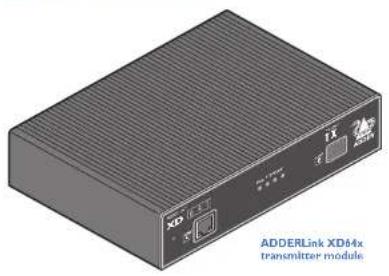
natural_image
Illustration of a 3D electronic device labeled 'ADDERLink XD44x transmitter module' (no other text or symbols visible)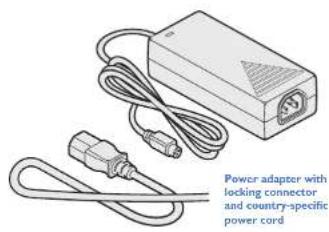
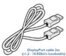
natural_image
Illustration of a display port cable with two connectors, labeled as 2m (v1.2 - 10.8 Gbit/s bandwidth)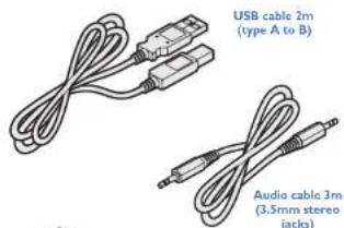
natural_image
Isometric view of a rectangular plate with internal lines and a circular mark, no text or symbols visible.XD64x receiver kit
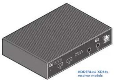
natural_image
Illustration of a 3D XRD device labeled 'ADDERLink XD64x receiver module' (no additional text or symbols)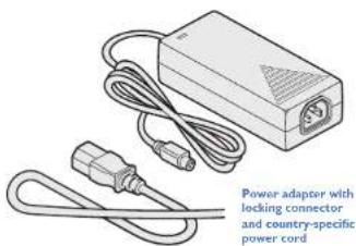
natural_image
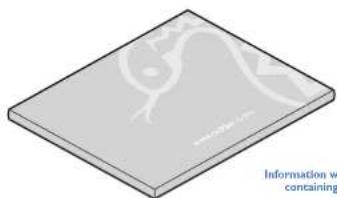
Isometric view of a flat rectangular plate with internal geometric patterns (no text or symbols)Information wallet
Quick setup guide
Eight self-achesive rubber feet
Safety documents

OPTIONAL EXTRAS

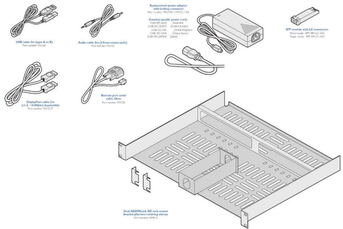
Replacement power adapter with locking connector Part number: PSU-IEC-12VDC-1.5A
Country-specific power cords
CAR-IEC-AIDS (Australia) CAR-IEC-EURO (Central Festival)
CAB-IEC-UK (United Kingdom)
CAB (EC USA (United States)
CAB-IEC-JAPAN (Japan)
Installation
LOCATIONS
Please consider the following important points when planning the position of the AdderLink XD64x modules:
- Situate the transmitter module close to the system to which it will be connected and near to a source of mains power. Place the receiver module in similar close proximity to the peripherals that it will connect with, plus a source of mains power.
- Consult the precautions listed within the supplied safety leaflet.
- Connections do not need to be carried out in the order given within this guide, however, where possible connect the power in as the final step.
Suitable for installation in Information
Technology Rooms in accordance with Article 645 of the National Electrical Code and NFPA 75.
Installation involves linking the transmitter module to various ports on the host computer, while the receiver module is attached to your video display(s) and peripherals:
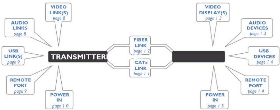
flowchart
graph TD
    A["TRANSMITTER"] --> B["VIDEO LINK(S)\npage 8"]
    A --> C["FIBER LINK\npage 1 2"]
    A --> D["CATx LINK\npage 1 1"]
    A --> E["VIDEO DISPLAY(S)\npage 1 3"]
    A --> F["AUDIO LINKS\npage 8"]
    A --> G["USB LINK(S)\npage 9"]
    A --> H["REMOTE PORT\npage 9"]
    A --> I["POWER IN\npage 10"]
    A --> J["POWER IN\npage 15"]
    A --> K["AUDIO DEVICES\npage 1 3"]
    A --> L["USB DEVICES\npage 1 4"]
    A --> M["REMOTE PORT\npage 1 4"]
Click a connection to see details

Transmitter video link(s)
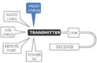
AdderLink XD641 and XD642 modules can transfer various high resolution video modes via their DisplayPort connectors. The XD641 models support a single video display while XD642 models support dual video displays.
Note: On XD642 models, dual video displays at 4K resolution are not possible using a CATx link - fiber must be used. However, dual 2K resolutions are possible using CATx.
flowchart
graph TD
    A["VIDEO LINK(S)"] --> B["TRANSMITTER"]
    C["AUDIO LINKS"] --> B
    D["USB LINK(S)"] --> B
    E["REMOTE PORT"] --> B
    F["POWER IN"] --> B
    G["LINK"] --> H["RECEIVER"]
    H --> I["Output"]
To connect the video port(s)
Connect the supplied DisplayPort link cable between the video socket I on the transmitter module rear panel and the primary video output socket of the host computer.
2 On XD642 models, optionally connect an additional DisplayPort link cable between the video socket 2 on the transmitter module rear panel and the primary video output socket of the host computer.
On XD641 models, optionally connect a local video display to video socket 2 on the transmitter module rear panel.
Primary video input from the host computer
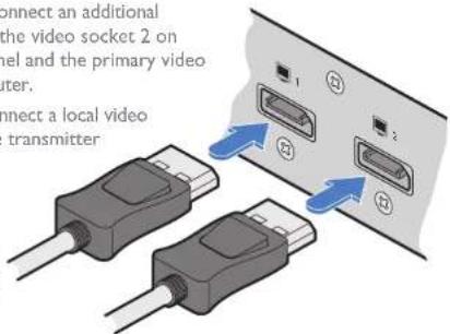
XD641 models: Output to a local video display (optional)
XD642 models: Secondary video input from the host computer
Video resolutions
| The XD641 and XD642 extenders support, but are not limited to, the following common video resolutions (all at 60 fps): | 1920 x 1080 (HD) | 2560 x 2048 (QSXGA) |
| 1920 x 1200 (WUXGA) | 2048 x 1080 (2K) | |
| 2560 x 1080 | 2048 x 2160 | |
| 2560 x 1440 (WQHD) | 3840 x 2160 (UHD) | |
| 2560 x 1600 (WQXGA) | 4096 x 2160 (4K) |
Transmitter audio links
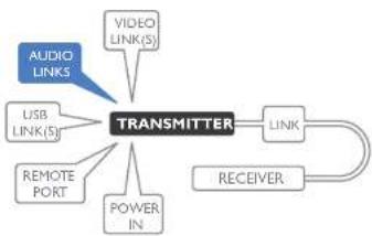
The AdderLink XD64x modules support analog stereo audio in and out connections. Where necessary, make connections between the audio input and/or output ports of the host computer and the transmitter module.
Note: Digital audio is also supported separately via the DisplayPort connectors as a transparent link-through.
To connect the audio ports
For the line in and/or line out ports, connect the supplied audio link cable between the audio port on the transmitter module rear panel and the line in or line out socket of the host computer.
From the audio output on the host computer
flowchart
graph TD
    A["VIDEO LINK(S)"] --> B["TRANSMITTER"]
    C["AUDIO LINKS"] --> B
    D["USB LINK(S)"] --> B
    E["REMOTE PORT"] --> B
    F["POWER IN"] --> B
    G["LINK"] --> B
    H["RECEIVER"] --> B
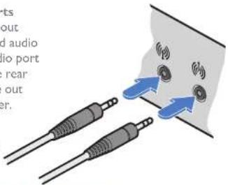
To the audio input on the host computer
Transmitter USB links
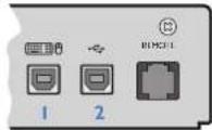
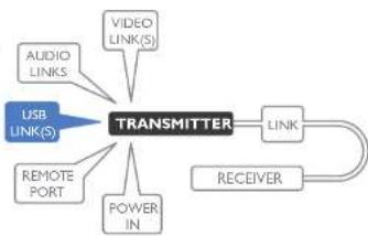
The transmitter module has two USB input ports on its rear panel:
flowchart
graph TD
    A["USB LINK(S)"] --> B["TRANSMITTER"]
    C["VIDEO LINK(S)"] --> B
    D["AUDIO LINKS"] --> B
    E["REMOTE PORT"] --> B
    F["POWER IN"] --> B
    G["LINK"] --> H["RECEIVER"]
    B --> I["LINK"]
The ports have different functions depending on the model of ADDERLink XD that you are using:
| 1 | 2 | ||
| XD641 | USB HID (Human Interface Device) feed to all USB ports on the receiver | USB audio feed to/from the analog audio ports labeled ☐ ☐ ☐ ☐ ☐ ☐ ☐ ☐ ☐ ☐ ☐ ☐ ☐ ☐ ☐ ☐ ☐ ☐ ☐ ☐ ☐ ☐ ☐ ☐ ☐ ☐ ☐ ☐ ☐ ☐ ☐ ☐ ☐ ☐ ☐ ☐ ☐ ☐ ☐ ☐ ☐ ☐ ☐ ☐ ☐ ☐ ☐ ☐ ☐ ☐ ☑ ☐ ☐ ☐ ☐ ☐ ☐ ☐ ☐ ☐ ☐ ☐ ☐ ☐ ☐ ☐ ☐ ☐ ☐ ☐ ☐ ☐ ☐ ☐ ☐ ☐ ☐ ☐ ☐ ☐ ☐ ☐ ☐ ☐ ☐ ☐ ☐ ☐ ☐ ☐ ☐ ☐ ☐ ☐ ☐ ☐ ☐ ☐ ☐ ☐ ☶ ☐ ☐ ☐ ☐ ☐ ☐ ☐ ☐ ☐ ☐ ☐ ☐ ☐ ☐ ☐ ☐ ☐ ☐ ☐ ☐ ☐ ☐ ☐ ☐ ☐ ☐ ☐ ☐ ☐ ☐ ☐ ☐ ☐ ☐ ☐ ☐ ☐ ☐ ☐ ☐ ☐ ☐ ☐ ☐ ☐ ☐ ☐ ☐ ☐ ☎ ☐ ☐ ☐ ☐ ☐ ☐ ☐ ☐ ☐ ☐ ☐ ☐ ☐ ☐ ☐ ☐ ☐ ☐ ☐ ☐ ☐ ☐ ☐ ☐ ☐ ☐ ☐ ☐ ☐ ☐ ☐ ☐ ☐ ☐ ☐ ☐ ☐ ☐ ☐ ☐ ☐ ☐ ☐ ☐ ☐ ☐ ☐ ☐ ☐ ☒ ☐ ☐ ☐ ☐ ☐ ☐ ☐ ☐ ☐ ☐ ☐ ☐ ☐ ☐ ☐ ☐ ☐ ☐ ☐ ☐ ☐ ☐ ☐ ☐ ☐ ☐ ☐ ☐ ☐ ☐ ☐ ☐ ☐ ☐ ☐ ☐ ☐ ☐ ☐ ☐ ☐ ☐ ☐ ☐ ☐ ☐ ☐ ☐ ☐ ☓ ☐ ☐ ☐ ☐ ☐ ☐ ☐ ☐ ☐ ☐ ☐ ☐ ☐ ☐ ☐ ☐ ☐ ☐ ☐ ☐ ☐ ☐ ☐ ☐ ☐ ☐ ☐ ☐ ☐ ☐ ☐ ☐ ☐ ☐ ☐ ☐ ☐ ☐ ☐ ☐ ☐ ☐ ☐ ☐ ☐ ☐ ☐ ☐ ☐ ★ ☐ ☐ ☐ ☐ ☐ ☐ ☐ ☐ ☐ ☐ ☐ ☐ ☐ ☐ ☐ ☐ ☐ ☐ ☐ ☐ ☐ ☐ ☐ ☐ ☐ ☐ ☐ ☐ ☐ ☐ ☐ ☐ ☐ ☐ ☐ ☐ ☐ ☐ ☐ ☐ ☐ ☐ ☐ ☐ ☐ ☐ ☐ ☐ ☐ ☽ ☐ ☐ ☐ ☐ ☐ ☐ ☐ ☐ ☐ ☐ ☐ ☐ ☐ ☐ ☐ ☐ ☐ ☐ ☐ ☐ ☐ ☐ ☐ ☐ ☐ ☐ ☐ ☐ ☐ ☐ ☐ ☐ ☐ ☐ ☐ ☐ ☐ ☐ ☐ ☐ ☐ ☐ ☐ ☐ ☐ ☐ ☐ ☐ ☐ ☜ ☐ ☐ ☐ ☐ ☐ ☐ ☐ ☐ ☐ ☐ ☐ ☐ ☐ ☐ ☐ ☐ ☐ ☐ ☐ ☐ ☐ ☐ ☐ ☐ ☐ ☐ ☐ ☐ ☐ ☐ ☐ ☐ ☐ ☐ ☐ ☐ ☐ ☐ ☐ ☐ ☐ ☐ ☐ ☐ ☐ ☐ ☐ ☐ ☐ ☞ ☐ ☐ ☐ ☐ ☐ ☐ ☐ ☐ ☐ ☐ ☐ ☐ ☐ ☐ ☐ ☐ ☐ ☐ ☐ ☐ ☐ ☐ ☐ ☐ ☐ ☐ ☐ ☐ ☐ ☐ ☐ ☐ ☐ ☐ ☐ ☐ ☐ ☐ ☐ ☐ ☐ ☐ ☐ ☐ ☐ ☐ ☐ ☐ ☐ ☖ ☐ ☐ ☐ ☐ ☐ ☐ ☐ ☐ ☐ ☐ ☐ ☐ ☐ ☐ ☐ ☐ ☐ ☐ ☐ ☐ ☐ ☐ ☐ ☐ ☐ ☐ ☐ ☐ ☐ ☐ ☐ ☐ ☐ ☐ ☐ ☐ ☐ ☐ ☐ ☐ ☐ ☐ ☐ ☐ ☐ ☐ ☐ ☐ ☐ ☋ ☐ ☐ ☐ ☐ ☐ ☐ ☐ ☐ ☐ ☐ ☐ ☐ ☐ ☐ ☐ ☐ ☐ ☐ ☐ ☐ ☐ ☐ ☐ ☐ ☐ ☐ ☐ ☐ ☐ ☐ ☐ ☐ ☐ ☐ ☐ ☐ ☐ ☐ ☐ ☐ ☐ ☐ ☐ ☐ ☐ ☐ ☐ ☐ ☐ ☉ ☐ ☐ ☐ ☐ ☐ ☐ ☐ ☐ ☐ ☐ ☐ ☐ ☐ ☐ ☐ ☐ ☐ ☐ ☐ ☐ ☐ ☐ ☐ ☐ ☐ ☐ ☐ ☐ ☐ ☐ ☐ ☐ ☐ ☐ ☐ ☐ ☐ ☐ ☐ ☐ ☐ ☐ ☐ ☐ ☐ ☐ ☐ ☐ ☐ ☸ ☐ ☐ ☐ ☐ ☐ ☐ ☐ ☐ ☐ ☐ ☐ ☐ ☐ ☐ ☐ ☐ ☐ ☐ ☐ ☐ ☐ ☐ ☐ ☐ ☐ ☐ ☐ ☐ ☐ ☐ ☐ ☐ ☐ ☐ ☐ ☐ ☐ ☐ ☐ ☐ ☐ ☐ ☐ ☐ ☐ ☐ ☐ ☐ ☐ ☻ ☐ ☐ ☐ ☐ ☐ ☐ ☐ ☐ ☐ ☐ ☐ ☐ ☐ ☐ ☐ ☐ ☐ ☐ ☐ ☐ ☐ ☐ ☐ ☐ ☐ ☐ ☐ ☐ ☐ ☐ ☐ ☐ ☐ ☐ ☐ ☐ ☐ ☐ ☐ ☐ ☐ ☐ ☐ ☐ ☐ ☐ ☐ ☐ ☐ ☃ ☐ ☐ ☐ ☐ ☐ ☐ ☐ ☐ ☐ ☐ ☐ ☐ ☐ ☐ ☐ ☐ ☐ ☐ ☐ ☐ ☐ ☐ ☐ ☐ ☐ ☐ ☐ ☐ ☐ ☐ ☐ ☐ ☐ ☐ ☐ ☐ ☐ ☐ ☐ ☐ ☐ ☐ ☐ ☐ ☐ ☐ ☐ ☐ ☐ ☰ ☐ ☐ ☐ ☐ ☐ ☐ ☐ ☐ ☐ ☐ ☐ ☐ ☐ ☐ ☐ ☐ ☐ ☐ ☐ ☐ ☐ ☐ ☐ ☐ ☐ ☐ ☐ ☐ ☐ ☐ ☐ ☐ ☐ ☐ ☐ ☐ ☐ ☐ ☐ ☐ ☐ ☐ ☐ ☐ ☐ ☐ ☐ ☐ ☐ ☆ ☐ ☐ ☐ ☐ ☐ ☐ ☐ ☐ ☐ ☐ ☐ ☐ ☐ ☐ ☐ ☐ ☐ ☐ ☐ ☐ ☐ ☐ ☐ ☐ ☐ ☐ ☐ ☐ ☐ ☐ ☐ ☐ ☐ ☐ ☐ ☐ ☐ ☐ ☐ ☐ ☐ ☐ ☐ ☐ ☐ ☐ ☐ ☐ ☐ ☔ ☐ ☐ ☐ ☐ ☐ ☐ ☐ ☐ ☐ ☐ ☐ ☐ ☐ ☐ ☐ ☐ ☐ ☐ ☐ ☐ ☐ ☐ ☐ ☐ ☐ ☐ ☐ ☐ ☐ ☐ ☐ ☐ ☐ ☐ ☐ ☐ ☐ ☐ ☐ ☐ ☐ ☐ ☐ ☐ ☐ ☐ ☐ ☐ ☐ ☦ | |
| XD642 | USB HID (Human Interface Device) feed to all USB ports on receiver except the one labeled | Transparent USB feed to front panel socket labeled | |
To connect the USB port(s)
Connect the type B connector of the supplied USB/video cable to the right-hand side USB port (labeled '2' on the diagram above) on the rear panel of the transmitter module.
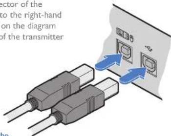
USB links from the host computer
2 Connect the type A connector of the cable to a vacant USB port on the host computer.
3 Repeat steps 1 and 2 for the second port if USB audio/transparent USB are required (see table above).
Transmitter Remote port
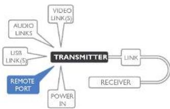
The Remote port has a dual role, it can either:
- Allow an optional remote control to be connected to the module, or
• Create an RS232 serial connection with the receiver module.
When serial devices are attached to the Remote ports on the transmitter and
receiver modules, the units transparently convey the signals between them at rates up to 115200 baud - no serial configuration is required. An optional serial cable (part number: VSC50) is available from Adder.
To connect the Remote port
I Use the optional serial cable (VSC50) to link the Remote port on the rear panel of the transmitter module with a vacant RS232 serial port on your host computer.
flowchart
graph TD
    A["TRANSMITTER"] --> B["LINK"]
    A --> C["RECEIVER"]
    A --> D["POWER IN"]
    A --> E["USB LINK(S)"]
    A --> F["AUDIO LINKS"]
    A --> G["VIDEO LINK(S)"]
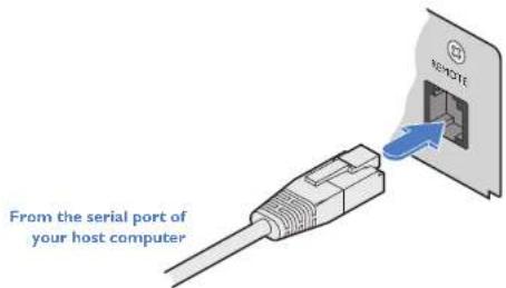
Please see Appendix I for pin-out details of the Remote port.
Transmitter power connection
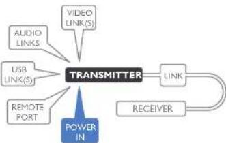
There is no on/off switch on either of the AdderLink XD64x modules, so operation begins as soon as power is applied. The power adapters supplied with the modules use locking-type plugs to help prevent accidental disconnections; please follow the instructions shown on the right whenever disconnecting a power adapter.
flowchart
graph TD
    A["TRANSMITTER"] --> B["VIDEO LINK(S)"]
    A --> C["USB LINK(S)"]
    A --> D["REMOTE PORT"]
    A --> E["POWER IN"]
    A --> F["LINK"]
    F --> G["RECEIVER"]
    G --> A
To connect the power adapter
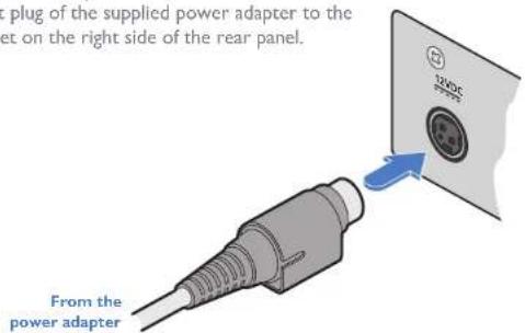
1 Attach the output plug of the supplied power adapter to the power input socket on the right side of the rear panel.
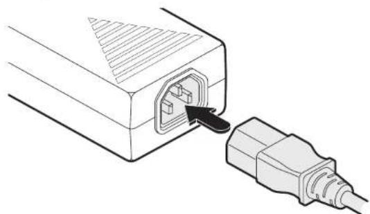
2 Connect the IEC connector of the supplied country-specific power cord to the socket of the power adapter.
natural_image
Diagram of an electrical plug inserted into a socket, showing internal port and cable connection (no text or labels)3 Connect the power cord to a nearby mains supply socket.
To disconnect the power adapter
I Isolate the power adapter from the mains supply.
2 Grasp the outer body of the power adapter plug where it connects with the module.
3 Gently pull the body of the outer plug away from the module. As the body of the plug slides back, it will release from the socket and you can fully withdraw the whole plug.
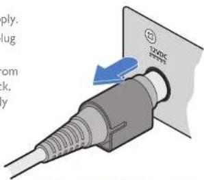
Gently pull back the plug outer body to release the lock
IMPORTANT: Please read and adhere to the electrical safety information given within the supplied safety leaflet. In particular, do not use an unearthed power socket or extension cable.
Note: Both the modules and the power supplies generate heat when in operation and will become warm to the touch. Do not enclose them or place them in locations where air cannot circulate to cool the equipment. Do not operate the equipment in ambient temperatures exceeding 40 degrees Centigrade. Do not place the products in contact with equipment whose surface temperature exceeds 40 degrees Centigrade.
Linking
ADDERLink XD641 and XD642 units can be linked using either:
• CATx (see below), or
- Fiber (see next page)
When fiber is used there are no limits to the resolutions that can be transferred, up to the maximum 4K (4096 x 2160); when a CATx link is used, the maximum resolution for dual head installations on XD642 models will be 2K (2048 x 1080).
Fiber CATx
ADDERLink XD641 Single head at 4K maximum Single head at 4K maximum
ADDERLink XD642
Dual head at 4K maximum
Single head at 4K maximum
Distances up to 4km
Dual head at 2K maximum
Distances up to 100m
CATx link
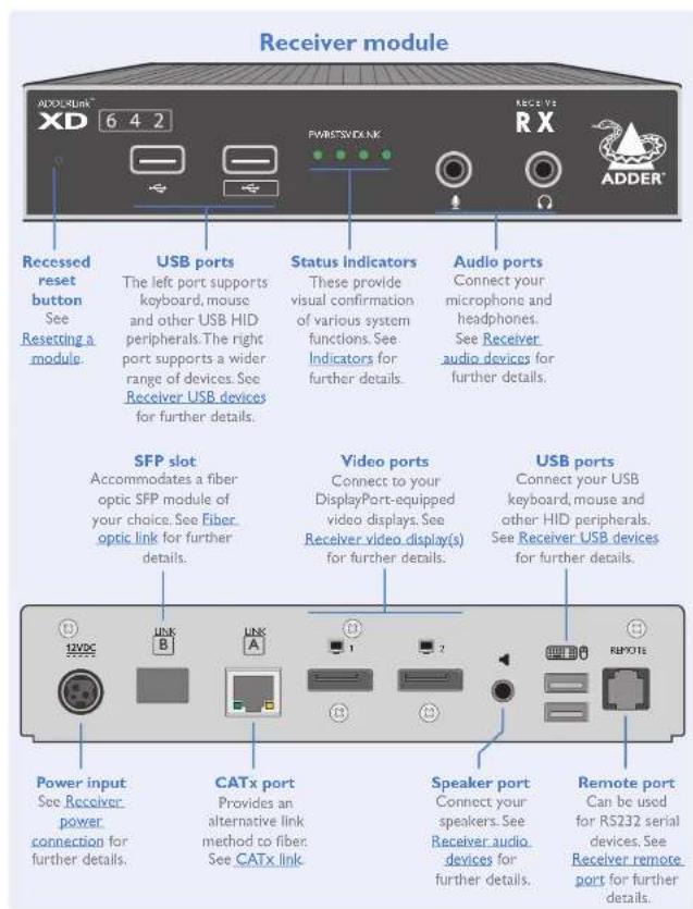
The CATx ports on each module (labeled Link A) allow you to create direct links of up to 50m (when using CAT5e) or 100m (when using CAT6). In order to work in CATx mode, the SFP fiber modules must be removed from their sockets.
Note: The CATx ports are not network ports and should not be connected to network switches or computer ports.
To make the CATx link
Connect a CATx (CAT 5e to 7 as required) cable between the Link A ports on the transmitter (front panel) and the receiver (rear panel):
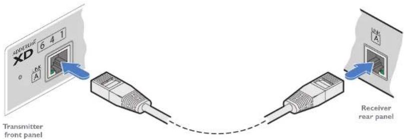
2 In operation, ensure that both indicators on the CATx connectors are green. See right.
CATx status indicators
The status indicators on the CATx port connector of each module provide further status information when a CATx link is in use:
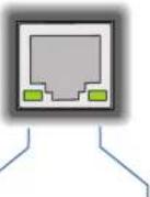
LINK
This indicator will be green whenever there is a CATx link between the transmitter and receiver modules.
SPEED
This indicator signals whether the speed of the CATx link is sufficient:
- amber - link speed is below the necessary SGbit/sec. Check the CATx cable link for problems.
- green - link speed is olc.

INSTALLATIONCONFIGURAT
FURTHER INFORMATION
INDEX
Fiber optic link
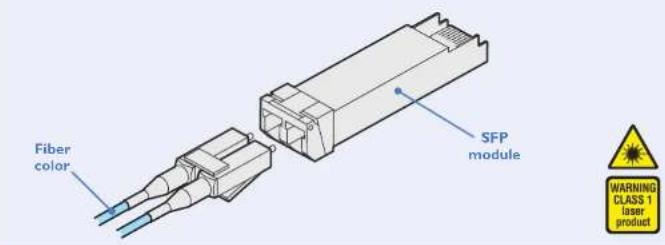
Each pair of AdderLink XD641 modules require optional SFP fiber optic modules of your choice (single or multi-mode). The fiber optic cable used must match the SFP type and also be of a suitable type for the distance being covered. See Transmission distances for details.
To make the fiber optic link
IMPORTANT: Ensure the power supply is off/disconnected before inserting or removing an SFP module.
I Remove an SFP module from its protective packing and insert it fully into the empty slot on the AdderLink XD641. The XD641 transmitter slot is located on the front panel; the XD641 receiver slot is situated on the rear panel:
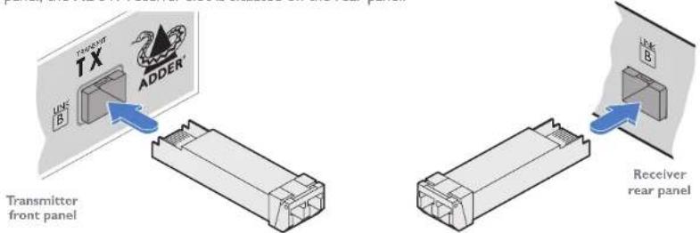
2 Repeat for the other SFP module on the other XD641.
3 For each SFP module, remove the black rubber insert that protects the sensors.
4 If fitted, remove the dual inserts that protect the fiber optic connectors.
5 Insert the fiber optic connectors into the SFP module so that they click into place:
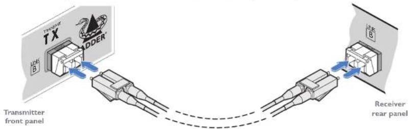
6 Repeat steps 4 and 5 at the other end.

Note: In order to maintain a high level of confidence in the fiber optic link, it is recommended that Adder supplied SFPs are used: (SFP-MM-LC-10G or SFP-SM-LC-10G).
If alternative parts are used, the system will detect this and will flash the front panel LNK indicator.
To remove an SFP module
If fitted, remove the dual fiber optic connectors from the SFP module (press in the release tab of the fiber optic connectors to disengage them).
2 Unclip the small extraction lever and open it out (this action releases a locking tab and also provides a grip point).
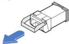
3 Gently pull on the extraction lever to withdraw the SFP module from the slot.
4 If the SFP module and/or fiber optic connector will remain unused for any period of time, be sure to fit the protective inserts to keep the optical interfaces clean.
Receiver video display(s)
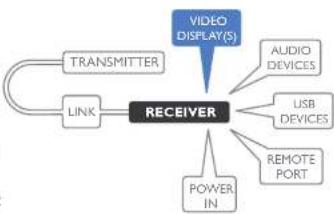
Two DisplayPort sockets are provided on the rear panel of each receiver module. On XD641 models, the signal from port 1 is duplicated on port 2. On XD642 models, ports 1 and 2 operate independently to supply the signals introduced to video ports 1 and 2 on the transmitter.
Note: On XD642 models, dual video displays at 4K resolution are not possible using a CATx link
- fiber must be used. However, dual 2K resolutions are possible using CATx.
flowchart
graph TD
    A["TRANSMITTER"] --> B["RECEIVER"]
    C["LINK"] --> B
    D["VIDEO DISPLAY(S)"] --> B
    E["AUDIO DEVICES"] --> B
    F["USB DEVICES"] --> B
    G["REMOTE PORT"] --> B
    H["POWER IN"] --> B
To connect the video display
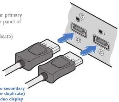
I Connect the signal cable from your primary video display to port I on the rear panel of the receiver module.
2 Repeat for the secondary (or duplicate) video display on port 2.
To primary video display
EDID management
The EDID (Extended Display Identification Data) is read from the connected video display at the receiver module; it is then transferred to, and stored within, the transmitter module and then declared to the host computer. If the video display is removed then the cloned EDID stored at the transmitter module will still be presented to the video source.
Video resolutions
| The XD641 and XD642 extenders support, but are not limited to, the following common video resolutions (all at 60 fps): | 1920 x 1080 (HD) | 2560 x 2048 (QSXGA) |
| 1920 x 1200 (WUXGA) | 2048 x 1080 (2K) | |
| 2560 x 1080 | 2048 x 2160 | |
| 2560 x 1440 (WQHD) | 3840 x 2160 (UHD) | |
| 2560 x 1600 (WQXGA) | 4096 x 2160 (4K) |
Receiver audio devices
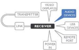
The receiver module can support multiple analog audio devices, such as stereo headphones, a mono microphone or line-level in/out connections.
USB audio is also supported when the left hand USB socket on the XD641 rear panel is connected to the computer. The audio signals received from the computer will be transferred to the analog audio sockets on
the receiver. USB audio will take precedence over the 3.5mm audio jacks when both sources are present.
flowchart
graph TD
    A["TRANSMITTER"] --> B["RECEIVER"]
    C["LINK"] --> B
    B --> D["VIDEO DISPLAY(S)"]
    B --> E["USB DEVICES"]
    B --> F["REMOTE PORT"]
    B --> G["POWER IN"]
    B --> H["AUDIO DEVICES"]
To connect audio devices
Connect stereo headphones and/or a mono microphone to the 3.5mm jack audio sockets on the front panel of the receiver module.
From mono microphone
To stereo headphones
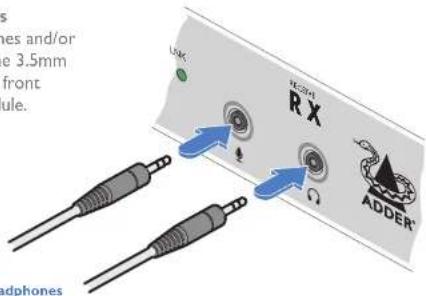
2 Optionally use the rear panel 3.5mm jack audio socket to connect line-level audio devices, such as powered speakers.
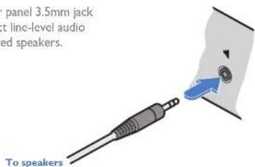
Note: Digital audio sent via the DisplayPort connectors are passed straight through from the transmitter to the receiver ports and remain completely separate from the analog audio signals.
Receiver USB devices
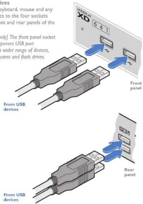
Each receiver module contains a USB hub that can support up to multiple v2.0 or v1.1 USB HID (Human Interface Device) peripherals. On XD641 models, all four USB sockets are identical in operation. However, on XD642 models, three of the USB sockets are used for HID peripherals while the fourth, labeled front panel) is a fully transparent USB port capable of supporting a wider range of devices.
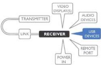
flowchart
graph TD
    A["TRANSMITTER"] --> B["RECEIVER"]
    C["LINK"] --> B
    B --> D["VIDEO DISPLAY(S)"]
    B --> E["AUDIO DEVICES"]
    B --> F["USB DEVICES"]
    B --> G["REMOTE PORT"]
    B --> H["POWER IN"]
To connect USB devices
Connect your USB keyboard, mouse and any other two USB devices to the four sockets distributed on the front and rear panels of the receiver module.
Note: [XD642 models only] The front panel socket labeled is fully transparent USB port capable of supporting a wider range of devices, such as headsets, web cams and flash drives.
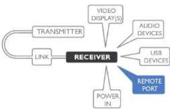
Receiver Remote port
The Remote port has a dual role, it can either:
- Allow an optional remote control to be connected to the module, or
• Create an RS232 serial connection with the receiver module.
When serial devices are attached to the Remote ports on the transmitter and
receiver modules, the units transparently convey the signals between them at rates up to 115200 baud - no serial configuration is required. An optional serial cable (part number: VSC50) is available from Adder.
To connect the Remote port
I Use the optional serial cable (VSC50) to link the Remote port on the rear panel of the transmitter module with a vacant RS232 serial port on your host computer.
flowchart
graph TD
    A["TRANSMITTER"] --> B["RECEIVER"]
    C["LINK"] --> B
    D["VIDEO DISPLAY(S)"] --> B
    E["AUDIO DEVICES"] --> B
    F["USB DEVICES"] --> B
    G["POWER IN"] --> B
    H["REMOTE PORT"] --> B
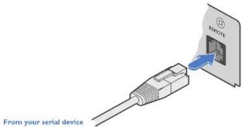
Please see Appendix 1 for pin-out details of the Remote port.
Receiver power connection
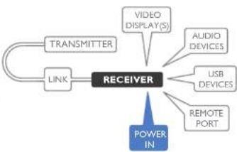
There is no on/off switch on either of the AdderLink XD64x modules, so operation begins as soon as power is applied. The power adapters supplied with the modules use locking-type plugs to help prevent accidental disconnections; please follow the instructions shown on the right whenever disconnecting a power adapter.
flowchart
graph TD
    A["TRANSMITTER"] --> B["RECEIVER"]
    C["LINK"] --> B
    D["VIDEO DISPLAY(S)"] --> B
    E["AUDIO DEVICES"] --> B
    F["USB DEVICES"] --> B
    G["REMOTE PORT"] --> B
    H["POWER IN"] --> B
To connect the power adapter
1 Attach the output plug of the supplied power adapter to the power input socket on the right side of the rear panel.
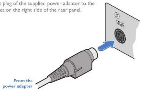
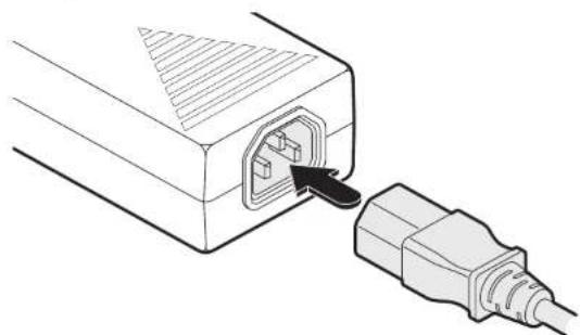
2 Connect the IEC connector of the supplied country-specific power cord to the socket of the power adapter.
natural_image
Line drawing of an electrical plug inserted into a socket (no text or symbols)3 Connect the power cord to a nearby mains supply socket.
To disconnect the power adapter
I Isolate the power adapter from the mains supply.
2 Grasp the outer body of the power adapter plug where it connects with the module.
3 Gently pull the body of the outer plug away from the module. As the body of the plug slides back, it will release from the socket and you can fully withdraw the whole plug.
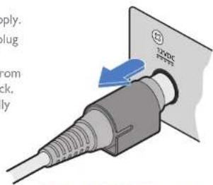
Gently pull back the plug outer body to release the lock
IMPORTANT: Please read and adhere to the electrical safety information given within the supplied safety leaflet. In particular, do not use an unearthed power socket or extension cable.
Note: Both the modules and the power supplies generate heat when in operation and will become warm to the touch. Do not enclose them or place them in locations where air cannot circulate to cool the equipment. Do not operate the equipment in ambient temperatures exceeding 40 degrees Centigrade. Do not place the products in contact with equipment whose surface temperature exceeds 40 degrees Centigrade.
Configuration
ACCESSING THE DASHBOARD
AdderLink XD641 modules generally configure themselves automatically, collecting EDID information from the attached monitor(s) and passing the details to the host computer. Unless an issue is encountered, the modules will begin working together correctly as soon as they are connected. The front panel indicators provide the primary source of status information, however, there is also a Dashboard popup which provides certain other details on the primary console display.
To access the dashboard
Using your console keyboard attached to the receiver module, press (and release) the Ctrl key three times in quick succession (either of the keyboard's Ctrl keys can be used). In response, the three keyboard indicators will all flash, once per second.
2 Press the numeric key 1 located above the main section of the keyboard (not the numeric keypad).
The Dashboard will be displayed, similar to this:
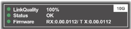
The example above shows a configuration that is working correctly.
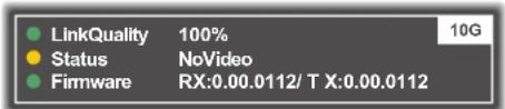
If the communication link was working correctly, but the video signal was lost, it might report as follows:
If the communication link was missing then the dashboard would report the issue similar to this:
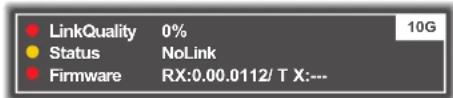
To exit the dashboard
- Press (and release) the Ctrl key three times in quick succession and then press the numeric key I located above the main section of the keyboard (not the numeric keypad).
CHOOSING THE DUAL HEAD MODE (XD642 models only)
When the CATx link is used to connect the transmitter and receiver modules, the available bandwidth is reduced. On XD642 models, if dual high resolution video displays are used, you can determine how the available bandwidth is shared between them. Two modes are available:
- Balanced mode - Shares the available video bandwidth equally between the two video displays, regardless of the EDIDs being reported by them, e.g. 1920x1200 each on video displays that would ordinarily request a native mode of 2560x1600.
- Priority mode - The primary video port will take priority, allowing it to display resolutions up to 4K, as reported by its EDID. The remaining bandwidth will be assigned to the second video head.
To choose the dual head mode
Using your console keyboard attached to the receiver module, press (and release) the Ctrl key three times in quick succession (either of the keyboard's Ctrl keys can be used). In response, the three keyboard indicators will all flash, once per second.
2 Press the numeric key located above the main section of the keyboard (not the numeric keypad) which represents the required mode:
• 6 for Balanced mode,
• 7 for Priority mode.
The current mode will be displayed on the Dashboard next to the link speed, eg BAL 5G, PRI 5G.
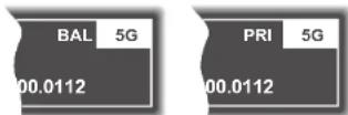
Note: If you do not press any key within five seconds, or press any key other than the digits 1, 6 or 7 (or once you have successfully chosen an action), the keyboard will revert to normal operation. To use another hotkey function, repeat the whole procedure described above.
The color of the Dashboard's Link Quality indicator matches the front panel LNK indicator:
• Red 0-25% quality
• Amber 25-50% quality
• Yellow 50-75% quality
• Green 75-100% quality
RESETTING A MODULE
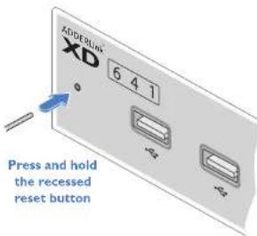
On the left side of the front panel of each module, you will find a small reset hole which is used to invoke special functions.
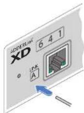
To reset a module
I Use a thin implement, such as a straightened paperclip to press and release the button concealed behind the small hole. The PWR indicator will show red.
After a few seconds, the indicator will change from red to green to show that the reset procedure is complete.
UPGRADING FIRMWARE
Firmware upgrades are periodically made available for products via the Adder website (www.adder.com). Use this procedure to upgrade the firmware in both ADDERLink XD extenders.
To upgrade the firmware
Download the appropriate firmware upgrade file from the Downloads section of the ADDERLink XD product page within the Adder website. Copy the upgrade file to an empty (but FAT32-formatted) USB memory stick.
2 Ensure that the transmitter and receiver are linked and powered on. Also check that there are no USB drives inserted in the receiver module's ports.
3 On the receiver, press and hold a thin implement, such as a straightened paperclip, in the reset hole until the receiver's STS indicator flashes red/blue. The receiver is now in upgrade mode.
4 Wait for the STS indicator link to turn green, signifying that the link is established.
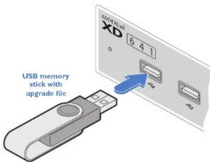
5 Insert the memory stick containing the upgrade file into the front panel left USB port.
The upgrade should begin and both units will flash their STS indicators red/green to show the upgrade process is in progress. Following a successful upgrade, both units will automatically reboot and run the new firmware.
- If for any reason the upgrade fails, the STS indicator will change to red to indicate an error. Refer to the Dashboard for details (see page 17). If necessary, reboot the module to make it use the existing firmware version.
Operation
The AdderLink XD641 modules are designed to be transparent in operation; all peripherals should respond exactly as they would when situated next to your host computer.
INDICATORS
The transmitter and receiver modules contain various indicators to provide you with status information. Both modules have four red indicators on their front panels.
Status indicators
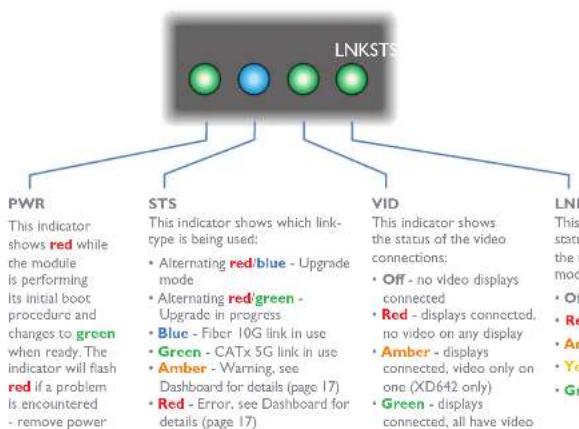
The multicolor status indicators on the front panels of each module mostly behave in the same manner at the same time:
PWR
This indicator shows red while the module is performing its initial boot procedure and changes to green when ready. The indicator will flash red if a problem is encountered - remove power and re-apply to see if the problem persists.
STS
This indicator shows which link-type is being used:
• Alternating red/blue - Upgrade mode
- Alternating red/green - Upgrade in progress
• Blue - Fiber 10G link in use
• Green - CATx 5G link in use
• Amber - Warning, see
Dashboard for details (page 17)
- Red - Error, see Dashboard for details (page 17)
VID
This indicator shows the status of the video connections:
• Off - no video displays connected
• Red - displays connected, no video on any display
• Amber - displays connected, video only on one (XD642 only)
• Green - displays connected, all have video
LNK
This indicator shows the status of the link between the transmitter and receiver modules:
- Off - no link
• Red - 0-25% quality
• Amber - 25-50% quality - Yellow - 50-75% quality
• Green - 75-100% quality
CATx status indicators
The status indicators on the CATx port connector of each module provide further status information when a CATx link is in use:
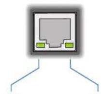
natural_image
Simple diagram of a network device with two ports and connecting lines (no text or labels)LINK
This indicator will be green whenever there is a CATx link between the transmitter and receiver modules.
SPEED
This indicator signals whether the speed of the CATx link is sufficient:
- Amber - link speed is below the necessary 5Gbit/sec. Check the CATx cable link for problems.
- Green - link speed is ok.

Further information
This chapter contains a variety of information, including the following:
• Getting assistance - see right
- Appendix I - Remote (Options) port pin-out
GETTING ASSISTANCE
If you are still experiencing problems after checking the information contained within this guide, then please refer to the Support section of our website:
www.adder.com

APPENDIX I - REMOTE PORT PIN-OUT
The REMOTE port uses a 6p6c socket. The pin-out is listed below.
Note: Although the pins labeled 'Not used' is inactive, it is still connected internally and so no links should be made at all to this pin.
REMOTE
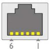
Pin Signal
I Sense/5V
2 Not used
3 Not used
4 GND
5 RX
6 TX
Note: The TX detects presence of an incoming power signal to determine whether 5V should be supplied at the RX.


www.adder.com
Documentation by:

www.ctxd.com
© 2020 Adder Technology Limited
All trademarks are acknowledged.
Part No. MAN-000008 • Release 1.1

Index
A
Audio devices Receiver 14
Audio links transmitter 9
B
Balanced mode 17
C
CATx link 12 status indicators 12 Connections overview 8
D
Dashboard 17 Dual head mode 17
F
Fiber distances 2
Fiber optic link 13
Firmware upgrade 18
H
HID 10
L
Linking overview 12
。
Optional extras 7 OSD Dashboard 17
P
Power connection Receiver 16 transmitter 11 Priority mode 17
R
Remote port pin-out 21 Receiver 15 transmitter 10
Reset 18
s
SFP module 13 SFP modules 2 Status indicators 19 Supplied items 6
U
Upgrade firmware 18 USB devices Receiver 15 USB links transmitter 10
V
Video display(s) Receiver 14 Video links transmitter 9 Video resolutions 9


- ADDERLink™ XD641 and XD642
- Contents
- Introduction
- Installation
- Configuration
- Operation
- Further information
- Index
- WELCOME
- Transmission distances when using fiber
- ADDERLINK XD641 FEATURES
- ADDERLINK XD642 FEATURES
- TECHNICAL SPECIFICATIONS
- ADDERLink XD641
- ADDERLink XD642
- SUPPLIED ITEMS
- OPTIONAL EXTRAS
- LOCATIONS
- Transmitter video link(s)
- To connect the video port(s)
- Transmitter audio links
- To connect the audio ports
- Transmitter USB links
- To connect the USB port(s)
- Transmitter Remote port
- To connect the Remote port
- Transmitter power connection
- To connect the power adapter
- To disconnect the power adapter
- IMPORTANT: Please read and adhere to the electrical safety information given within the supplied safety leaflet. In particular, do not use an unearthed power socket or extension cable.
- Linking
- Fiber CATx
- CATx link
- To make the CATx link
- CATx status indicators
- SPEED
- Fiber optic link
- To make the fiber optic link
- To remove an SFP module
- Receiver video display(s)
- To connect the video display
- EDID management
- Receiver audio devices
- To connect audio devices
- Receiver USB devices
- To connect USB devices
- Receiver Remote port
- Receiver power connection
- ACCESSING THE DASHBOARD
- To access the dashboard
- To exit the dashboard
- CHOOSING THE DUAL HEAD MODE (XD642 models only)
- To choose the dual head mode
- RESETTING A MODULE
- To reset a module
- UPGRADING FIRMWARE
- To upgrade the firmware
- INDICATORS
- Status indicators
- PWR
- STS
- VID
- LNK
- LINK
- GETTING ASSISTANCE
- APPENDIX I - REMOTE PORT PIN-OUT
- A
- B
- C
- D
- F
- H
- L
- 。
- P
- R
- s
- U
- V
Brand : Adder
Model : XD642P-DP
Category : Network Equipment