
AW-RP150G - Remote control PANASONIC - Free user manual and instructions
Find the device manual for free AW-RP150G PANASONIC in PDF.
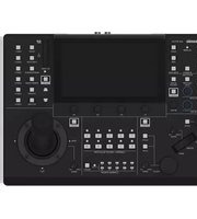


| Product Type | Remote Camera Controller |
| Brand | Panasonic |
| Model | AW-RP150G |
| Dimensions (W x H x D) | 342 mm x 178 mm x 245 mm (13-15/32 in x 7 in x 9-21/32 in) |
| Weight | Approx. 3.2 kg (7.05 lb) |
| Power Supply | 12 V DC (10.8 V to 13.2 V) or PoE+ (42 V – 57 V DC) |
| Current Consumption | 1 A (DC 12 V) / 0.6 A (PoE+) |
| Maximum Cameras Controlled (IP) | 200 |
| Maximum Cameras Controlled (Serial) | 5 |
| Supported Connections | IP (10BASE-T/100BASE-TX), RS-422 Serial, 3G SDI |
| Operating Temperature | 0 °C to 40 °C (32 °F to 104 °F) |
| Operating Humidity | 10% to 90% (no condensation) |
| Main Features | Pan/tilt lever, zoom/focus rocker, color adjustment (white balance, black balance, gain, pedestal), preset memory, tracing memory, PoE+ support, CROpping function, user buttons, GPIO interface |
| Memory Card Support | SD, SDHC (4–32 GB), SDXC (64 GB) |
| Display | Built-in LCD panel for status and menu display |
| Safety Precautions | Installation by qualified personnel only; avoid water, moisture, and flammable materials; maintain ventilation |
| Cleaning | Turn off power, wipe with dry cloth; use mild detergent for stubborn dirt; avoid volatile fluids |
| User Serviceable Parts | None – refer servicing to qualified personnel |
| Compliance | FCC Class A, CAN ICES-3 (A)/NMB-3(A) |
Frequently Asked Questions - AW-RP150G PANASONIC
User questions about AW-RP150G PANASONIC
0 question about this device. Answer the ones you know or ask your own.
Ask a new question about this device
Download the instructions for your Remote control in PDF format for free! Find your manual AW-RP150G - PANASONIC and take your electronic device back in hand. On this page are published all the documents necessary for the use of your device. AW-RP150G by PANASONIC.
USER MANUAL AW-RP150G PANASONIC
Operating Instructions
Remote Camera Controller
AW-RP150G


Before operating this product, please read the instructions carefully and save this manual for future use.
Please carefully read the "Read this first!" (pages 3 to 4) of this Manual before use.
| български | Посетете следния уебсайт относно информация за безопасността и важни уведомления за продукта. | Latviešu | Lai iegūtu informāciju par drošību un skatītu svarīgus paziņojumus par šo produktu, apmeklējiet tālāk norādīto tīmekļa vietni. |
| Hrvatski | Za sigurnosne informacije i važne obavijesti o proizvodu posjetite sljedeću internetsku stranicu. | Lietuvių | Jei reikia saugos informacijos ir svarbių pranešimų apie gaminį, apsilankykite toliau nurodytoje svetainėje. |
| Čeština | Na následujícím webu najdete bezpečnostní informace a dūležité poznámky k tomuto produktu. | Polski | Informacje o bezpieczeństwie i ważne informacje o produkcie znajdują się w ponižszej witrynie internetowej. |
| Dansk | Besøg følgende webside for sikkerhedsinformation og vigtige bemærkninger vedrørende produktet. | Português | Consulte o seguinte website para as informações de segurança e importantes notificações sobre o produto. |
| Nederlands | Ga naar de volgende website voor veiligheidsinformatie en belangrijke meldingen over het product. | Romānă | Vizitați urmātoarea pagină web pentru informații de securitate și notificări importante cu privire la produs. |
| Eesti | Toodet puudutava ohutusteabe ja oluliste märkuste saamiseks külastage järgmist veebilehte. | Slovensky | Pre bezpečnostné informácie a dōležité oznámenia súvisiace s produktom navštívte túto webovú stránku. |
| Suomi | Käy seuraavalla verkkosivulla saadaksesi turvallisuustietoja ja tärkeitä tietoja liittyen laitteeseen. | Slovenščina | Za varnostne informacije in pomembna obvestila v zvezi z izdelkom obiščite naslednje spletno mesto. |
| Ελληνικά | Για πληροφορίες σχετικά με θέματα ασφάλειας και σημαντικές ειδοποιήσεις που αφορούν το προϊόν σας, επισκεφτείτε τον ιστότοπο που ακολουθεί. | Svenska | Besök följande webbplats för säkerhetsinformation och viktiga meddelanden om produkten. |
| Magyar | A termékkel kapcsolatos biztonsági információkért és fontos értesítésekért látogasson el az alábbi weboldalra. |
https://pro-av.panasonic.net/manual/en/index.html
About trademarks and registered trademarks
- Microsoft Windows®, Windows® 7, Windows® 10 and Internet Explorer® are registered trademarks or trademarks of Microsoft Corporation in the United States, Japan, and/or other countries.
- SDXC logo is a trademark of SD-3C, LLC.
- Other company names and product names appearing in this manual are the registered trademarks or trademarks of their respective companies.
Copyrights
It is prohibited to transfer, copy, disassemble, decompile, and reverse engineer the software included with the unit, as well as export it in violation of the export laws.
Illustrations and screen images in this manual
● Illustrations of the unit and screens may appear different from the actual unit and screens. - The screenshots are used in accordance with the guidelines of Microsoft Corporation.
Abbreviations
The following abbreviations are used in this manual.
- Microsoft Windows® 7 Professional SP1 32/64-bit is referred to as "Windows 7".
- SDHC Memory Card and SDXC Memory Card are both referred to as "memory cards".
They are referred to individually in descriptions in which each of them is discussed separately.
- In these instructions, the phrases "4K Integrated Camera" and "pan-tilt head and camera combination" are referred to collectively as "remote camera" except in places where specific equipment is mentioned.
Furthermore, the product numbers of equipment are referred to as follows.
| Equipment part number Notation in this manual | |
| AW-RP150G AW-RP150 | |
| AW-UE150WP | AW-UE150 |
| AW-UE150KP | |
| AW-UE150WE | |
| AW-UE150KE | |
WARNING:
Installation should only be performed by qualified installation personnel. Improper installation may result in the entire apparatus falling down and causing injury.
WARNING:
• To reduce the risk of fire, do not expose this equipment to rain or moisture. - To reduce the risk of fire, keep this equipment away from all liquids. Use and store only in locations which are not exposed to the risk of dripping or splashing liquids, and do not place any liquid containers on top of the equipment.
WARNING:
Always keep memory cards or accessories out of the reach of babies and small children.
WARNING:
This equipment is compliant with Class A of CISPR 32. In a residential environment this equipment may cause radio interference.
CAUTION:
Do not remove panel covers by unscrewing. To reduce the risk of electric shock, do not remove the covers. No user serviceable parts inside. Refer servicing to qualified service personnel.
CAUTION:
To reduce the risk of fire or electric shock and annoying interference, use the recommended accessories only.
CAUTION:
In order to maintain adequate ventilation, do not install or place this unit in a bookcase, built-in cabinet or any other confined space. To prevent risk of electric shock or fire hazard due to overheating, ensure that curtains and any other materials do not obstruct the ventilation.

indicates safety information.
FCC NOTICE (USA)
Declaration of Conformity
Model Number: AW-RP150P
Trade Name: Panasonic
Responsible Party: Panasonic Corporation of North America
Two Riverfront Plaza, Newark, NJ 07102
Support contact: 1-800-524-1448
This device complies with part 15 of the FCC Rules.
Operation is subject to the following two conditions:
(1) This device may not cause harmful interference, and (2) this device must accept any interference received, including interference that may cause undesired operation.
FCC Note:
This equipment has been tested and found to comply with the limits for a class A digital device, pursuant to Part 15 of the FCC Rules. These limits are designed to provide reasonable protection against harmful interference when the equipment is operated in a commercial environment. This equipment generates, uses, and can radiate radio frequency energy, and if not installed and used in accordance with the instruction manual, may cause harmful interference to radio communications. Operation of this equipment in a residential area is likely to cause harmful interference in which case the user will be required to correct the interference at his own expense.
Warning:
To assure continued FCC emission limit compliance, the user must use only shielded interface cables when connecting to external units. Also, any unauthorized changes or modifications to this equipment could void the user's authority to operate it.
NOTIFICATION (Canada)
CAN ICES-3 (A)/NMB-3(A)

indicates safety information.
Turkey Only
AEEE Complies with Directive of Turkey.
EMC NOTICE FOR THE PURCHASER/USER OF THE APPARATUS
1. Pre-requisite conditions to achieving compliance with the above standards
<1> Peripheral equipment to be connected to the apparatus and special connecting cables
- The purchaser/user is urged to use only equipment which has been recommended by us as peripheral equipment to be connected to the apparatus.
- The purchaser/user is urged to use only the connecting cables described below.
For the connecting cables, use shielded cables which suit the intended purpose of the apparatus.
• Video signal connecting cables
Use double shielded coaxial cables, which are designed for 75-ohm type high-frequency applications, for SDI (Serial Digital Interface).
Coaxial cables, which are designed for 75-ohm type high-frequency applications, are recommended for analog video signals.
• Audio signal connecting cables
If your apparatus supports AES/EBU serial digital audio signals, use cables designed for AES/EBU.
Use shielded cables, which provide quality performance for high-frequency transmission applications, for analog audio signals.
• Other connecting cables (LAN, RS-422) Use shielded cables, which provide quality performance for high-frequency applications, as connecting cables. - When connecting to the DVI signal terminal, use a cable with a ferrite core. - If your apparatus is supplied with ferrite core(s), they must be attached on cable(s) following instructions in this manual.
2. Performance level
The performance level of the apparatus is equivalent to or better than the performance level required by these standards. However, the apparatus may be adversely affected by interference if it is being used in an EMC environment, such as an area where strong electromagnetic fields are generated (by the presence of signal transmission towers, cellular phones, etc.). In order to minimize the adverse effects of the interference on the apparatus in cases like this, it is recommended that the following steps be taken with the apparatus being affected and with its operating environment:
- Place the apparatus at a distance from the source of the interference.
- Change the direction of the apparatus.
- Change the connection method used for the apparatus.
- Connect the apparatus to another power outlet where the power is not shared by any other appliances.

Disposal of Old Equipment
Only for European Union and countries with recycling systems
This symbol on the products, packaging, and/or accompanying documents means that used electrical and electronic products must not be mixed with general household waste.
For proper treatment, recovery and recycling of old products, please take them to applicable collection points in accordance with your national legislation.
By disposing of them correctly, you will help to save valuable resources and prevent any potential negative effects on human health and the environment.
For more information about collection and recycling, please contact your local municipality, dealer or supplier.
Penalties may be applicable for incorrect disposal of this waste, in accordance with national legislation.
Manufactured by: Panasonic Corporation, Osaka, Japan
Importer's name and address of pursuant to EU rules:
Panasonic Marketing Europe GmbH
Panasonic Testing Centre
Winsbergring 15, 22525 Hamburg, Germany
Read this first! 3
Introduction 6
Features 7
Supported remote cameras 7
Precautions for use....8
Parts and their functions 9
Control panel....9
Rear panel....14
Precautions for installation 15
Connections.... 16
Examples of IP connections 16
Examples of serial connections.... 18
Basic operations of the unit.... 20
How to turn on and off the power of the remote cameras.... 21
How to turn on the power of the remote cameras 21
How to turn off the power of the remote cameras.... 22
Selecting a camera group.... 23
Selecting a remote camera.... 24
Status screen.... 25
Displaying and operating the status screen 25
Basic operations for the menus.... 27
Displaying menus and the menu configuration 27
Network settings of the unit 30
Settings for connecting with the remote cameras.... 32
Setting the connection types (serial/IP/no connection) for remote cameras 33
Setting the IP addresses automatically (auto IP setting).... 33
Manually setting the connection destination IP addresses (remote cameras) and port number. 38
Initializing the connection destination IP addresses set on the unit 38
Menu 39
Menu group 39
PAINT 40
FUNCTION 51
MAINTENANCE 57
SYSTEM 69
PMEM/TMEM 75
Setup Software 83
Installing the software 83
Configuring the settings of the personal computer 83
Settings for connecting with the remote cameras 84
Messages 88
Troubleshooting 90
Appearance 91
Specifications 92
Control interface for external devices....93
Index 97
Overview
This unit is a remote camera controller for controlling remote camera AW-UE150 (sold separately).
It can be used to control up to 200 remote cameras when IP connections are used, and up to 5 remote cameras when serial connections are used.
■ Required personal computer environment
For the software used with the unit, use a personal computer specified on the following website.
https://pro-av.panasonic.net/
■ Disclaimer of warranty
IN NO EVENT SHALL Panasonic Corporation BE LIABLE TO ANY PARTY OR ANY PERSON, EXCEPT FOR REPLACEMENT OR REASONABLE MAINTENANCE OF THE PRODUCT, FOR THE CASES, INCLUDING BUT NOT LIMITED TO BELOW:
(1) ANY DAMAGE AND LOSS, INCLUDING WITHOUT LIMITATION, DIRECT OR INDIRECT, SPECIAL, CONSEQUENTIAL OR EXEMPLARY, ARISING OUT OF OR RELATING TO THE PRODUCT; (2) PERSONAL INJURY OR ANY DAMAGE CAUSED BY INAPPROPRIATE USE OR NEGLIGENT OPERATION OF THE USER; (3) UNAUTHORIZED DISASSEMBLE, REPAIR OR MODIFICATION OF THE PRODUCT BY THE USER; (4) INCONVENIENCE OR ANY LOSS ARISING WHEN IMAGES ARE NOT DISPLAYED, DUE TO ANY REASON OR CAUSE INCLUDING ANY FAILURE OR PROBLEM OF THE PRODUCT; (5) ANY PROBLEM, CONSEQUENTIAL INCONVENIENCE, OR LOSS OR DAMAGE, ARISING OUT OF THE SYSTEM COMBINED BY THE DEVICES OF THIRD PARTY; (6) ANY INCONVENIENCE, DAMAGES OR LOSSES RESULTING FROM ACCIDENTS CAUSED BY AN INADEQUATE INSTALLATION METHOD OR ANY FACTORS OTHER THAN A DEFECT IN THE PRODUCT ITSELF; (7) LOSS OF REGISTERED DATA CAUSED BY ANY FAILURE; (8) ANY DAMAGE OR CLAIMS DUE TO LOSS OR LEAKAGE OF IMAGE DATA OR SETTING DATA SAVED ON THIS UNIT OR ON A MEMORY CARD OR PERSONAL COMPUTER.
■ Network security
This unit also has functions which are used when it is connected to a network.
Using the unit when it is connected to a network may possibly give rise to the following.
(1) Leakage or disclosure of information transmitted via this unit (2) Unauthorized use of this unit by a third person with malicious intent (3) Interference or stoppage of this unit by a third person with malicious intent
It is your responsibility to take sufficient network security measures such as those described below to protect yourself against the above risks.
Panasonic does not accept any responsibility for damage of this type.
- Use this unit in a network secured by a firewall, etc.
- If this unit is used in a system with a personal computer connected, make sure that checks for and removal of computer viruses and malicious programs are implemented regularly.
Also observe the following points.
- Do not install the unit in a location where the unit, cables, and other parts may be easily damaged.
User authentication
In order to protect device settings from exposure on the network, when connecting to a network, please enable user authentication to restrict access as appropriate.
Restrictions on use
It is recommended that the remote operation panel and all devices to be used with the remote operation panel be connected to the same network segment.
Events related to settings of network devices may occur if devices are connected to different segments, so verify operation carefully before placing devices into service.
■ Upgrade software
You can obtain the upgrade software from Service and Support on the following website.
https://pro-av.panasonic.net/
For the upgrade procedure, refer to the instructions included with the download file.
■ File types handled by the unit
| Camera configuration file | Configuration file data for the remote cameras. |
| RP configuration file | Configuration file especially for AW-RP150. |
| Tracing memory file | Tracing memory data file. |
IP connections and serial connections supported
IP connections
- Up to 200 remote cameras can be controlled via a network hub (switching hub).
- The unit's auto IP setting function can be used to automatically assign and control the IP addresses of the remote cameras 41 .
*1: Supported cameras: AW-UE150
- One remote camera can be simultaneously controlled from up to 5 units.
Serial connections
● Up to 5 remote cameras can be connected.
Cropping operations supported
- It is possible to crop HD images from 4K images (with the Crop function) by connecting the unit to AW-UE150.
Easy to operate the remote cameras
- The unit is equipped with dedicated levers, buttons, and dials for performing pan, tilt, zoom, and focus operations. Furthermore, there is a dedicated speed adjustment knob for each of them. Camera angle adjustment can be performed quickly and reliably.
- The unit is equipped with an AWB button and ABB button for executing automatic adjustment of the white balance and black balance. Furthermore, there are dedicated dials for adjusting the pedestal and gain for each of the R channel and B channel. Manual color adjustment is also easy.
- Rapid call up operations are available for shooting environments that frequently use presets.
Also, the speed at which a remote camera moves to a preset position (PRESET SPEED) can be memorized for each preset number of the unit. Thus, a remote camera can be operated at a different speed depending on the preset number in accordance with operation, enabling various image directing.
- Tracing memory is incorporated for recording a series of operations. It allows you to duplicate remote camera operations.
- The unit is equipped with PoE, eliminating the need for additional power supply cabling.
Connecting the unit to a network device that supports the PoE+ standard (IEEE802.3at compliant) *3 eliminates the need for power supply cabling on the unit.
Notes
- If you are using a PoE+ power supply device that requires software authentication, it may take some time for operation to become possible after power supply starts.
- If both an external DC power supply and a PoE+ power supply are connected, the power supply from the external DC power supply will be used. If the external DC power supply is disconnected from a state where both power supplies were connected, the unit will restart automatically and the image will be interrupted.
- Use a category 5e cable or higher for the PoE+ connection. The maximum cable length for the connection between the power supply device and the unit is 100 m (328.1 ft). Using a cable that is category 5 or lower may result in decreased power supply performance.
- When a personal computer that supports Gigabit Ethernet and a PoE+ injector are connected via a straight LAN cable, the unit may not be recognized by the personal computer. In such cases, connect the unit to the personal computer via a cross cable (or cross connection).
*2: Power over Ethernet Plus. Referred to as "PoE+" in this manual.
*3: For details on PoE+ power supply devices for which operation has been verified, consult your local dealer.
Supported remote cameras
● 4K Integrated Camera
AW-UE150
Observe the following in addition to the information included in "Read this first!".
Handle carefully
Do not drop the product, or subject it to a strong impact or vibration. Do not carry or move the product by the PAN/TILT lever or a dial. Doing so may cause a failure or accident.
Use the product in an ambient temperature of 0 °C to 40 °C (32 °F to 104 °F)
Exposure to temperatures below 0 °C (32 °F) or above 40 °C (104 °F) could adversely affect internal components.
Power off before connecting or disconnecting cables
Before connecting or disconnecting the cables, be sure to turn the power off.
Avoid humidity and dust
Avoid using the product in a very humid or dusty place because a lot of humidity and dust will cause damage to the internal parts.
Cleaning
Turn the power off and wipe the product with a dry cloth. To remove stubborn dirt, dip a cloth into a diluted solution of kitchen detergent (neutral detergent), wring it out well, and wipe the product gently. Then, wipe the product with a cloth dampened with water. Finally, wipe the product with a dry cloth.
Notes
● Avoid using benzine, paint thinners and other volatile fluids. - If a chemical cleaning cloth is to be used, carefully read through the precautions for its use.
Avoid open flames
Do not place candles and other sources open flame near the unit.
Avoid exposure to water
Make sure that the unit is not directly exposed to water. Exposure to water could damage it.
Disposal of the unit
When the unit has reached the end of its service life and is to be disposed of, ask a qualified contractor to dispose of the unit properly in order to protect the environment.
LCD panels
The pixels of the LCD panel are controlled to obtain high precision with 99.99% of the effective pixels. This leaves less than 0.01% of pixels that may not light or may remain on all the time. This is normal and will have no effect on the images you shoot.
There may be some unevenness on the screen depending on the image displayed.
Wiping or rubbing the LCD screen with a rough cloth may damage it.
LCD response time and brightness vary with operating temperature.
When the unit is left in a high-temperature and high-humidity location for prolonged periods, the LCD panel characteristics may change and result in uneven image quality.
Due to the characteristics of LCD panels, prolonged display of bright still images or prolonged operation in high-temperature or high-humidity environments may result in residual images, luminance reduction, burn-in, banding, or panel defects and degradation that result in areas of permanently changed brightness.
In addition, avoid prolonged continuous use in the following types of environments.
● Confined areas with high temperature and humidity ● Near the exhaust vent of air conditioning equipment, etc.
Prolonged use involving the images and environments described above will accelerate deterioration of the LCD panel over time.
To prevent deterioration over time and its related phenomena, we recommend the following.
- Do not display bright still images for prolonged periods. ● Lower the brightness.
- Turn off the power of the unit (and the power of the CCU and hub) when the unit is not in use.
Residual images will gradually disappear as different images are displayed.
PoE+ power supply
If you are using a PoE+ power supply device that requires software authentication, it may take some time for operation to become possible after power supply starts.
If both an external DC power supply and a PoE+ power supply are connected, the power supply from the external DC power supply will be used. If the external DC power supply is disconnected from a state where both power supplies were connected, the unit will restart automatically and the image and communication will be interrupted.
Use a category 5e cable or higher for the PoE+ connection. The maximum cable length for the connection between the power supply device and the unit is 100 m (328.1 ft). Using a cable that is category 5 or lower may result in decreased power supply performance.
When a personal computer that supports Gigabit Ethernet and a PoE+ injector are connected via a straight LAN cable, the unit may not be recognized by the personal computer. In such cases, connect the unit to the personal computer via a cross cable (or cross connection).
Control panel

Focus, zoom and iris section Camera selection section Pan and tilt section
① POWER indicator [POWER]
This turns on when the POWER switch (50) on the rear panel is set to ON while power is supplied to the DC IN socket (44).
② ALARM indicator [ALARM]
This turns on when an alarm (a cooling fan alarm or pan/tilt error) has been received from a remote camera.
③ LCD panel
This indicates the current setting statuses.
Menu operation section

④ F1 dial [F1], F2 dial [F2], F3 dial [F3], F4 dial [F4] (menu operation dials)
Use these dials to manipulate the items displayed on the LCD panel of the unit. When the status screen is displayed, use them to manipulate the item values displayed in the lower part of the LCD panel. When a menu screen is displayed, use them to manipulate the selected menu item values.
⑤PAINT button [PAINT]
Displays the PAINT menu on the LCD panel.
⑥FUNCTION button [FUNCTION]
Displays the FUNCTION menu on the LCD panel.
⑦ MAINTENANCE button [MAINTENANCE]
Displays the MAINTENANCE menu on the LCD panel.
⑧ PMEM/TMEM button [PMEM/TMEM]
Displays the PMEM/TMEM menu on the LCD panel.
⑨ SYSTEM button [SYSTEM]
Displays the SYSTEM menu on the LCD panel.
⑩ PICTURE button [PICTURE]
Displays the images being input through the 3G SDI terminal on the LCD panel.
Functions displayed on the LCD panel are switched by holding this button down.
Button indicator on: Crop frame displayed (Green)
Button indicator on: Both crop frame and focus assist (FOCUS IN (Amber) RED) displayed
- When operation of the PICTURE button is enabled (on), the following operations are available with the F1 to F4 dials.
F1: Press to select Crop Out YL.
F2: Press to select Crop Out G.
F3: Press to select Crop Out MG.
F4: When turned while the camera menu is being displayed, the cursor can be moved and values can be selected. Press the dial to confirm.
⑪ Menu operation ENABLE button [ENABLE]
Enables or disables operations with the menu operation section, user button section, and LCD panel.
Hold down to turn the LCD panel off.
Button indicator on : Operations with the menu operation section, user button section, and LCD panel are enabled.
Button indicator off : Operations with the menu operation section, user button section, and LCD panel are disabled.
⑫ Cursor movement buttons
Moves the cursor on the menu screen up or down one line. When the PICTURE button is on, use this to switch the crop frame.
Camera selection section
⑬ Mode selection button [SELECT]
Each press of this switches the operation mode of the camera selection buttons (14), changing as follows; Off → On (with camera group 1 to 10 selected) → On (with camera group 11 to 20 selected) and the [11-20] indicator (camera group 11 to 20).
Button indicator off : Camera selection mode
Button indicator on : Camera group selection mode (1 to 10). Camera group selection mode (11 to 20). (The [11-20] indicator lights at this time.)
14 Camera selection buttons
[CAMERA / GROUP SELECTION 1 to 10]
Use these to select the remote camera or camera group to control from the unit.
Pressing any of [1] to [10] in camera selection mode switches to the corresponding remote camera.
Pressing any of [1] to [10] in camera group selection mode switches to the corresponding camera group and turns on the corresponding camera group indicator (15).
After a camera group is selected, the camera selection buttons return to the camera selection mode.
- When in the camera group selection mode, the camera selection buttons light blue. Only the button for the camera group currently selected lights amber.
⑮ Camera group indicators [CAMERA GROUP 1 to 20]
The indicator for the selected camera group number is on. When a camera group between 11 and 20 is selected, the [11-20] indicator lights.
⑯ Camera status indicators [1] to [10]
These indicate the statuses of the remote cameras assigned to [1] to [10].
For details, refer to "Selecting a remote camera" (page 24).
Pan and tilt section
⑰ PAN/TILT lever
Use this to control the direction in which the currently selected remote camera points.
The movement speed differs depending on the angle to which the PAN/TILT lever is moved.
Moved left or right : The camera points to the left or right.
Moved toward you or away from you:
The camera points up or down.
- When the [PAN DIR] and [TILT DIR] items in the [PTZ INFO2] FUNCTION menu are set to "REVERSE", it is possible to change the relationship between the direction that the lever is tilted and the direction the camera moves.
Note
- When turning on the power, do not touch until the status screen is displayed on the LCD panel.
18 ZOOM/FOCUS rocker
You can control the focus or zoom function by allocating this button.
Note
- When turning on the power, do not touch until the status screen is displayed on the LCD panel.
19 PAN/TILT SPEED dial [SPEED]
Use this to adjust the operation speed variation amount for PAN/TILT lever operation.
Turned clockwise : Operation is at a higher speed (HI)
Turned counterclockwise : Operation is at a lower speed (LOW)
20 PAN/TILT ENABLE button [ENABLE]
Use this to enable the PAN/TILT lever and ZOOM/FOCUS rocker.
Button indicator on: PAN/TILT lever operation is enabled. (Amber)
Button indicator off: PAN/TILT lever operation is disabled.
(Hold down the button)
- When the PICTURE button is on, this button turns green when you press it and it switches to operate the crop frame.
Focus, zoom and iris section![graph TD A["28"] --> B["27"] B --> C["IRIS"] C --> D["AUTO"] D --> E["26"] E --> F["25"] F --> G["TELE"] G --> H["ZOOM"] H --> I["WIDE"] I --> J["21"] J --> K["24"] K --> L["23"] L --> M["22"] M --> N["29"] N --> O["22"] O --> P["23"] P --> Q["24"] Q --> R["24"] R --> S["24"] S --> T["24"] T --> U["…](/content/2026/05/812394/images/241005b7bf76f5e397c6176672148c58c58aa661195769c3b876a3dbb695971c.jpg)
⑳ FOCUS dial [FOCUS]
Use this to manually control the focus. During auto focusing (when the auto focus button [2] indicator is on), operation is disabled.
Turned clockwise: The focus moves to the far end. Turned counterclockwise: The focus moves to the near end.
- When the [FOCUS DIR] item in the [PTZ INFO2] FUNCTION menu is set to "REVERSE", it is possible to change the relationship between the direction that the FOCUS dial is turned and the direction of the focus operation.
22 Auto focus button [AUTO]
Use this to set focus control to "Auto (auto focus)". During auto focusing, operation of the FOCUS dial (21) and one-touch auto focus button (23) is disabled.
Button indicator on: Auto focus Button indicator off: Manual focus
23 One-touch auto focus button [OTAF]
When this button is pressed during manual focusing (when the auto focus button [12] indicator is off), the button indicator turns on for a brief moment and the auto focusing operation is performed to bring the subject into focus.
24 FOCUS SPEED dial [SPEED]
Use this to adjust the operation variation amount for FOCUS dial (21) operation.
Turned clockwise : Operation is at a higher speed (HI) Turned counterclockwise: Operation is at a lower speed (LOW)
- When the ZOOM/FOCUS rocker on the PAN/TILT lever is allocated to FOCUS, operation is according to this setting.
25 ZOOM button [ZOOM]
Use this to adjust the lens zoom. The zooming speed changes depending on the extent to which the button is pressed.
When the TELE side is pressed: Moves toward the telephoto end. When the WIDE side is pressed: Moves toward the wide-angle end.
- When the [ZOOM DIR] item in the [PTZ INFO2] FUNCTION menu is set to "REVERSE", it is possible to change the relationship between the direction that the ZOOM button is pushed and the direction of the zoom operation of the lens.
Note
- When turning on the power, do not touch until the status screen is displayed on the LCD panel.
26 ZOOM SPEED dial [SPEED]
Use this to adjust the operation variation amount for ZOOM button (25) operation.
Turned clockwise : Operation is at a higher speed (HI) Turned counterclockwise: Operation is at a lower speed (LOW)
- When the ZOOM/FOCUS rocker on the PAN/TILT lever is allocated to ZOOM, operation is according to this setting.
27 IRIS dial [IRIS]
During manual iris (when the auto iris button [20] indicator is off), use this to manually control the lens iris. During auto iris (when the auto iris button [20] indicator is on), use this to adjust the convergence level of the auto iris of the remote camera.
Turned clockwise: The lens iris opens. Turned counterclockwise: The lens iris closes.
28 Auto iris button [AUTO]
Use this to set lens iris control to "Auto (auto iris)".
Button indicator on: Auto iris Button indicator off: Manual iris
29 FOCUS/ZOOM/IRIS ENABLE button [ENABLE]
Use this to enable or disable operation of the FOCUS dial (21), ZOOM button (25) and IRIS dial (27).
Button indicator on: Operation of the FOCUS dial, ZOOM button and IRIS dial is enabled.
Button indicator off: Operation of the FOCUS dial, ZOOM button and IRIS dial is disabled.
Color adjustment section
![graph TD A["30"] --> B["BADS"] C["32"] --> D["ABERANS"] E["33"] --> F["BYD500K WHITE SAL"] G["34"] --> H["SHUTTER ON"] I["35"] --> J["BYD500K ALTYVISA 3200K"] K["36"] --> L["SCREW ON/OFF"] M["37"] --> N["ENABLE"] O["38"] --> P["R/B GAIN"] Q["39"] --> R["N/B PED"] S["30"] --> T["M.PED"]](/content/2026/05/812394/images/55ea79abe687fe6a63f5e014445af65bfd4896bac42f44d6f09e6edddea5ee4b.jpg)
30 BARS button [BARS]
Use this to select the video signal output from the remote camera. Each press switches between the "signal for the images shot by the camera" and the "color bar signal".
Button indicator off: Outputs the signal for the images shot by the camera
Button indicator on: Outputs the color bar signal
31 AWB button [AWB]
Use this to execute automatic adjustment of the white balance and then register the adjustment result to memory A or B of the remote camera.
The AWB button indicator turns on during white balance adjustment and turns off when adjustment is successful. When adjustment was not possible, the indicator turns off.
- When automatic adjustment of the white balance ends, the R GAIN and B GAIN values become ±0.
- If the AWB button is pressed when the color bar signal is output from the remote camera (when the BARS button (80) indicator is on) or when ATW is selected (when the ATW/VAR button (33) indicator is on), the adjustment is not made and the button indicator turns on.
- When adjustment was not possible, try changing, for example, the light source, lens iris, and subject, and then perform adjustment again.
③2 ABB button [ABB]
Use this to execute automatic adjustment of the black balance. When the button is pressed, adjustment is performed by automatically closing the iris.
The ABB button indicator blinks during black balance adjustment and turns off when adjustment is successful. When adjustment was not possible, the indicator turns on and the black balance setting does not change.
- When adjustment was not possible, check the camera and lens cable connections, and then perform adjustment again.
③3 WHITE BAL A/3200K, B/5600K, ATW/VAR buttons [WHITE BAL A/3200K, B/5600K, ATW/VAR]
Use these to select the white balance mode of the remote camera.
A/3200K: ● Press the A/3200K button to switch to the white balance state registered in memory A of the remote camera and to turn on the A/3200K button indicator in amber.
Pressing the AWB button (31) after the A/3200K button automatically adjusts the white balance and registers the adjustment result to memory A of the camera.
- Holding down the A/3200K button sets the color temperature to 3200K and turns on the A/3200K button indicator in green.
B/5600K: ● Press the B/5600K button to switch to the white balance state registered in memory B of the remote camera and to turn on the B/5600K button indicator in amber.
Pressing the AWB button (31) after the B/5600K button automatically adjusts the white balance and registers the adjustment result to memory B of the camera.
- Holding down the B/5600K button sets the color temperature to 5600K and turns on the B/5600K button indicator in green.
ATW/VAR: ● Press the ATW/VAR button to switch to the auto tracking white balance (ATW) mode for automatically tracking the white balance in accordance with the lighting conditions and to turn on the ATW/VAR button indicator in amber.
- Holding down the ATW/VAR button sets the color temperature to one set in the menu and turns on the ATW/VAR button indicator in green.
34 SHUTTER ON button [SHUTTER ON]
Button indicator on: Shutter is enabled.
Button indicator off: Shutter is disabled.
- Refer to the operating instructions for the remote camera being connected for setting value ranges.
35 SHUTTER SYNC button [SHUTTER SYNC]
Button indicator on: Sync shutter is set. Button indicator off: Step shutter is set.
- Refer to the operating instructions for the remote camera being connected for setting value ranges.
36 SCENE ON/OFF button [SCENE ON/OFF]
This is a button for a future expansion feature. Currently it is constantly on.
37 M.PED dial [M.PED]
Use this to adjust the master pedestal.
Turned clockwise: Displays the setting value of the master pedestal on the LCD panel and changes the value in the plus (+) direction.
Turned counterclockwise: Displays the setting value of the master pedestal on the LCD panel and changes the value in the minus (−) direction.
- Refer to the operating instructions for the remote camera being connected for setting value ranges.
38 R/B GAIN dials [R/B GAIN]
Use these to individually adjust the gain of the R channel and B channel (R GAIN and B GAIN) in order to set the desired white balance. The adjustment value is registered to memory A or B of the remote camera.
Turned clockwise: Displays the setting values of the
R GAIN and B GAIN on the LCD panel and changes the value in the plus (+) direction.
Turned counterclockwise: Displays the setting values of the R GAIN and B GAIN on the LCD panel and changes the value in the minus (−) direction.
- If these dials are turned when ATW is selected (when the ATW/VAR button [69] indicator is on), “---” appears on the LCD panel and the white balance settings are not changed.
39 R/B PED dials [R/B PED]
Use these to individually adjust the pedestal of the R channel and B channel (R PED and B PED) in order to set the desired black balance.
Turned clockwise: Displays the setting values of the R PED and B PED on the LCD panel and changes the value in the plus (+) direction.
Turned counterclockwise: Displays the setting values of the R PED and B PED on the LCD panel and changes the value in the minus (−) direction.
- Refer to the operating instructions for the remote camera being connected for setting value ranges.
40 Color adjustment ENABLE button [ENABLE]
Use this to enable or disable operation of the color adjustment section.
Button indicator on: Operation of the color adjustment section is enabled.
Button indicator off: Operation of the color adjustment section is disabled.
Memo
- You can view the setting values on the status screen of the LCD panel by operating the M.PED dial (37), the R/B GAIN dial (38), and the R/B PED dial (39).
User button section

④ USER buttons [USER 1] to [USER 6]
Use these to access the functions assigned to USER 1 to USER 6.
Memory card section

42 Memory card slot
Insert an SD Memory Card (sold separately), SDHC Memory Card (sold separately), or SDXC Memory Card (sold separately).
43 Memory card access lamp
This is lit while the memory card is being accessed. (It blinks when access for a short period of time is performed repeatedly.)
Do not turn off the power of the unit or remove the memory card while the access lamp is lit or blinking. Doing so may cause the data in the memory card to become corrupt.
● Memory cards
Use memory cards in the unit that conform to the SDHC standards/SDXC standards.
Be sure to use the unit to format memory cards.
Memory cards with the following capacity can be used with the unit.
The MultiMedia Card (MMC) is not supported.
| SDHC 4 | GB to 32 GB |
| SDXC 64 | GB |
For the latest information not described in the Operating Instructions, refer to the following websites.
https://pro-av.panasonic.net/
- Observe the following points when using and storing the memory cards.
- Avoid high temperature and humidity.
- Avoid water droplets.
- Avoid static electricity.
Rear panel
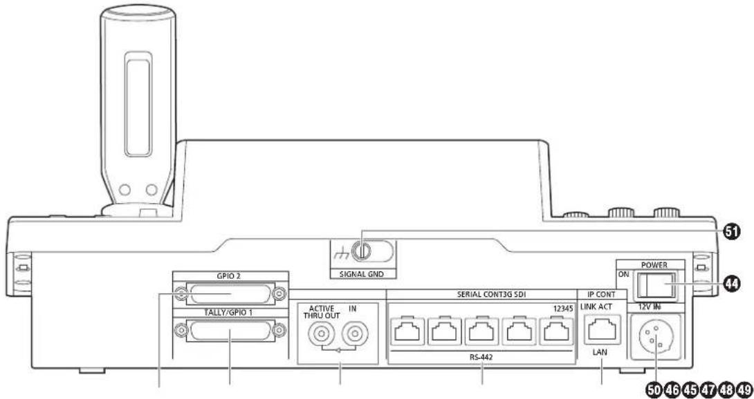
44 POWER switch [POWER]
When the POWER switch is set to the ON position, the POWER indicator (1) lights, and the unit can be operated.
45 SERIAL CONT 1 to 5 connectors
[SERIAL CONT 1 to 5] (RJ-45)
Connect remote cameras that support a serial connection to these connectors with LAN cables.
Connect them with straight cables (category 5e or better shielded cable).
For details, refer to "Connections" (pages 16 to 19).
Note
- Do not connect cables for PoE+ power supply to these connectors.
④6 IP CONT connector [IP CONT] (RJ-45)
(10BASE-T/100BASE-TX)
Connect a remote camera or computer that supports an IP connection to this connector with a LAN cable.
When directly connecting a device to the unit, use a crossover cable (category 5e or better shielded cable).
When connecting via a hub (switching hub) etc., use a straight cable or a cross cable (category 5e cable).
For details, refer to "Connections" (pages 16 to 19).
47 3G SDI terminal [3G SDI]
Use to input and output HD SDI signals.
- When the power of the unit is off, signals are not output from the ACTIVE THRU OUT connector.
For details, refer to "Connections" (pages 16 to 19).
48 TALLY/GPIO 1 connector [TALLY/GPIO 1]
JST: JBY-25S-1A3F(LF)(SN)
Connect an external device to this connector to receive tally information or send the camera selection status.
Use a shielded cable to connect to the connector.
④9 GPIO 2 connector [GPIO 2]
JST: JBY-25S-1A3F(LF)(SN)
Connect an external device to this connector to enable selection of cameras or perform preset playback.
Use a shielded cable to connect to the connector.
⑤ DC IN socket [12V — IN] (DC 12 V) (XLR connector)
Connect an external DC power supply to this connector.
- Use a DC cable with a length of max. 2 m (6.6 ft) (when using an AWG16 cable).
■External DC power supply
Connect after making sure that the output voltage of the external DC power supply is compatible with the rated voltage of the camera.
Select an output amperage for the external DC power supply with a margin above the total amperage of the connected devices.
The total amperage of connected devices can be calculated with the following formula.
Total power consumption ÷ voltage
When the power of the camera is turned on, inrush current is generated. Insufficient power supply when turning on the power may cause a malfunction. We recommend that you use an external DC power supply that can assure double the capacity of the total power consumption of the camera and connected devices that are turned on by interlock when the power of the camera is turned on (such as lenses, wireless microphone receivers).
- Make sure of the pin alignment of the DC output terminal of the external DC power supply and the camera DC IN connector, and connect the polarity correctly. If the +12 V power supply is mistakenly connected to the GND terminal, it may cause fire or malfunction.
| 12V | ||
 | 1 | GND |
| 2 | — | |
| 3 | — | |
| 4 | +12V | |
| HA16RA-4P (77)Hirose Electric Co. | ||
⑤ Grounding terminal [SIGNAL GND]
Connect this to the system ground.
In addition to the safety precautions given in "Read this first!", also observe the following instructions.
Be sure to ask your dealer to perform the installation and connection work for the unit.
Connecting a power supply
- Insert the DC plug for the external DC power supply all the way in until it locks into place.

- When the unit will not be used for a long time, turn off the power switch and remove the DC plug for the external DC power supply to save power.
Do not allow any foreign objects to enter inside the unit
- Allowing water, metal items, food or drink, or other foreign objects to enter inside the unit may cause a fire or electric shock.
Installation location
● This unit is designed for indoor use only. ● Install and use the unit in a stable location. - Avoid installing the unit where it will be exposed to direct sunlight. - Installing the unit in a location with a lot of humidity, dust, or vibration may result in a failure.
Example of embedding the unit in a desktop
When using the unit embedded in a desktop, refer to the following procedure.
1. Make mount angles suitable for the installation location.
- Desk mounting side Unit: mm (inch)
- Unit mounting side

2. Attach the mount angles to the sides of the unit with four M3 screws.

Note
- For details on the dimensions for attaching mount angles to the unit, refer to "Appearance" (page 91).
3. Insert the unit into the desktop hole and then fix it in place with four screws.

- Provide screws that match the size of the desktop mounting holes (e.g., ∅5 mm [3/16 inches]).
4. If necessary, make and attach a panel to cover the rest of the desktop hole.

Examples of IP connections
■ IP connections for remote cameras (AW-UE150)
AW-UE150 AW-UE150
![graph TD A["LAN connector"] --> B["External DC power supply"] B --> C["Live Production Center AV-HLC100"] C --> D["Monitor 1"] C --> E["Monitor Monitor"] C --> F["External DC power supply"] D --> G["Switching hub"] E --> G F --> G G --> H["Remote camera controller AW-RP150"] H --> I["External DC pow…](/content/2026/05/812394/images/e1361868bb9b1c0d1353b05d30e630ade7280ad41c50bc1938a05092f2fde211.jpg)
- Use a category 5e cable for the LAN cable.
- It is possible to have a mixture of remote cameras connected via serial connections and remote cameras connected via IP connections. ● A total of up to 200 remote cameras connected via IP connections and serial connections can be registered as control destinations to one unit.
■IP connections for multiple units and remote cameras (AW-UE150)![graph TD A["External DC power supply"] --> B["External DC power supply"] B --> C["Remote camera controller AW-RP150"] C --> D["External DC power supply"] C --> E["External DC power supply"] C --> F["External DC power supply"] C --> G["External DC power supply"] C --> H["External DC power supply"] C…](/content/2026/05/812394/images/2bc1f5a715afb66962898e83ff3346f08dbd7c40bbd9639dd886199a4ac6da2e.jpg)
- Use a category 5e cable for the LAN cable. ● One remote camera can be simultaneously controlled from up to 5 units. (When IP connection)
■IP connection for one unit and one remote camera![graph LR A["External DC power supply"] --> B["Remote camera controller AW-RP150"] B --> C["LAN cable (Cross cable) Max. 100 m (328 ft)"] C --> D["External DC power supply"] D --> E["AW-UE150"]](/content/2026/05/812394/images/37b80585ae9946aa9628824e44ad8a63128ffb4272a09679abce546ff78025d7.jpg)
- Use a cross cable (category 5e cable) for the LAN cable.
- When connecting to any camera other than an AW-UE150, refer to the operating instructions for the camera.
Examples of serial connections
■Serial connections for (AW-UE150) remote cameras![graph TD A["RS-422 connector"] --> B["External DC power supply"] B --> C["Switcher"] C --> D["Monitor 1"] D --> E["Monitor Monitor"] E --> F["Remote camera controller AW-RP150"] F --> G["External DC power supply"] G --> H["SDI video signals"] H --> C E --> I["Monitor 2"] I --> J["Serial control sign…](/content/2026/05/812394/images/a44f26e3c1406917308f7d6a2e1b9c2c00b1f5eada63b60e2552b324c2729bc4.jpg)
- Use a straight cable (category 5e cable) for the LAN cable.
- When serial connections are used, up to five remote cameras can be connected to one unit.
- It is possible to have a mixture of remote cameras connected via IP connections and remote cameras connected via serial connections.
● A total of up to 200 remote cameras connected via IP connections and serial connections can be registered as control destinations to one unit.
■Example of connection for the function for cropping 4K images to HD images![graph TD A["External DC power supply"] --> B["MONI OUT"] B --> C["Monitor"] C --> D["3G SDI OUT"] D --> E["External DC power supply"] F["Remote camera controller AW-RP150"] --> G["Monitor"] G --> H["3G SDI ACTIVE THRU OUT"] H --> I["External DC power supply"] J["LAN cables (Straight cable or cross c…](/content/2026/05/812394/images/3487998161db3ac751a2d646792534a080eec5d68ab2af45af4f9afd27818d57.jpg)
- Use a category 5e cable for the LAN cable.
1. Turn on the unit's power.
Set the POWER switch to the ON position.
Power is supplied to the unit, and the POWER indicator turns on.
- When the "AUTO POWER" item in the "CAMERA" SYSTEM menu is set to "ON", the power of the remote camera turns on when the power of the unit is turned on.
However, this only works when the remote camera is in the standby state.
For details, refer to "How to turn on the power of the remote cameras" (page 21).
- Remote cameras are linked when the "CNNCT MD" item in the "CONNECT SETTING" SYSTEM menu is set to either "Serial" or "LAN".
For details, refer to "Setting the connection types (serial/IP/no connection) for remote cameras" (page 33).
2. Select a remote camera.
When the mode selection button [SELECT] indicator is on, press a [CAMERA / GROUP SELECTION] button to select the remote camera to control from the unit.
3. Adjust the direction in which the remote camera points.
When the PAN/TILT ENABLE button [ENABLE] indicator is on, use the PAN/TILT lever to adjust the direction in which the remote camera points.
Note
- When turning on the power, do not touch until the status screen is displayed on the LCD panel.
4. Adjust the zoom.
When the FOCUS/ZOOM/IRIS ENABLE button [ENABLE] indicator is on, use the ZOOM button to adjust the lens zoom. When the TELE side is pressed, the zoom is set to the telephoto mode, and when the WIDE side is pressed, it is set to the wide-angle mode.
Note
- When turning on the power, do not touch until the status screen is displayed on the LCD panel.
5. Adjust the lens iris.
When the FOCUS/ZOOM/IRIS ENABLE button [ENABLE] indicator is on, turn the IRIS dial to adjust the lens iris.
6. Adjust the focus.
When the FOCUS/ZOOM/IRIS ENABLE button [ENABLE] indicator is on, turn the FOCUS dial to adjust the lens focus. When the one-touch auto focus button is pressed during manual focusing, the mode switches to auto focusing mode temporarily, and the subject is brought into focus automatically.
- OTAF (one-touch auto focus) is enabled for remote cameras which are equipped with the OTAF function.
7. Turn off the unit's power.
Set the POWER switch to the OFF position.
The unit's power is turned off, and the POWER indicator turns off.
- When the unit's power is turned off, the power of the connected remote cameras does not turn off.
- To turn off the power of the remote cameras, select "ALL OFF" or "GROUP OFF" in the "CAM POWER" item of the "CAMERA" SYSTEM menu, and execute.
For details, refer to "How to turn off the power of the remote cameras" (page 22).

How to turn on the power of the remote cameras
The power of the remote cameras in the standby state can be turned on from the unit.
There are the following methods of turning on the power.
● Turning on the power one camera at a time - Turning on the power of the cameras simultaneously with the turning on of the unit's power ● Turning on the power of multiple cameras ◇Turning on the power of all the cameras ◇Turning on the power of the selected camera group
Each of these methods is described in turn below.
Turning on the power one camera at a time
1. Select the remote camera.
By holding down the applicable camera selection button [CAMERA / GROUP SELECTION] for about 3 seconds, the name of the remote camera and the "ON" and "OFF" buttons are displayed on the LCD panel.
Note
- This operation is available when the status screen is being displayed.
- With the camera selection button held down, touch the "ON" button on the LCD panel.

Turning on the power of the cameras simultaneously with the turning on of the unit's power
- Press the [SYSTEM] button.
- Touch "CAMERA" at the top of the LCD panel to display the "AUTO POWER" item.

- Turn the F2 dial to select "ON" and press the F2 dial. The power of remote cameras whose setting in the "CNNCT MD" item in the "CONNECT SETTING" SYSTEM menu is set to either "Serial" or "LAN" turns on when the unit's power is turned on.
Note
- Depending on the number of cameras connected, it may take some time before you can operate the unit.
Turning on the power of multiple cameras
- Press the [SYSTEM] button to light it.
- Touch "CAMERA" at the top of the LCD panel to display the "CAM POWER" item.

■ Turning on the power of all the cameras
- Turn the F1 dial to select "ALL ON" and press the F1 dial.
■ Turning on the power of the selected camera group
- Turn the F1 dial to select "GRP ON" and press the F1 dial.
How to turn off the power of the remote cameras
The power of the remote cameras can be turned off from the unit. There are the following methods of turning off the power.
● Turning off the power one camera at a time ● Turning off the power of multiple cameras ◇ Turning off the power of all the cameras ◇ Turning off the power of the selected camera group
Each of these methods is described in turn below.
Turning off the power one camera at a time
1. Select the remote camera.
By holding down the applicable camera selection button [CAMERA / GROUP SELECTION] for about 3 seconds, the name of the remote camera and the "ON" and "OFF" buttons are displayed on the LCD panel.
Note
- This operation is available when the status screen is being displayed.
2. While holding down the camera selection button, touch the "OFF" button on the LCD panel.

Turning off the power of multiple cameras
- Press the [SYSTEM] button.
- Touch "CAMERA" at the top of the LCD panel to display the "CAM POWER" item.

■ Turning off the power of all cameras
- Turn the F1 dial to select "ALL OFF" and press the F1 dial. ■ Turning off the power of the selected camera group
- Turn the F1 dial to select "GRP OFF" and press the F1 dial.
This unit allows you to register up to 200 remote cameras as control targets by configuring the connection settings for each of the camera numbers CAM1 to CAM200. To select a remote camera to control from these cameras, you need to select the camera group to which it belongs beforehand.
| Camera group | Camera numbers | Camera group | Camera numbers |
| 1 CAM1 | to CAM10 11 CAM101 to | CAM110 | |
| 2CAM1 | to CAM20 12 CAM111 to | CAM120 | |
| 3 CAM2 | to CAM30 13 CAM121 to | CAM130 | |
| 4 CAM3 | to CAM40 14 CAM131 to | CAM140 | |
| 5 CAM4 | to CAM50 15 CAM141 to | CAM150 | |
| 6 CAM5 | to CAM60 16 CAM151 to | CAM160 | |
| 7 CAM6 | to CAM70 17 CAM161 to | CAM170 | |
| 8 CAM7 | to CAM80 18 CAM171 to | CAM180 | |
| 9CAM8 | to CAM90 19 CAM181 to | CAM190 | |
| 10 CAM9 | to CAM100 20 CAM191 to | CAM200 |
Selecting a camera group
1. Press the mode selection button [SELECT] to turn on the button indicator.
The camera selection buttons [CAMERA / GROUP SELECTION] light blue.
Groups that can be selected light amber.
2. Press the camera selection button [CAMERA / GROUP SELECTION] to select the camera group to which the remote camera you want to control belongs.
When the camera group is selected, the corresponding camera group indicator [CAMERA GROUP] lights, and the unit moves to the camera selection mode for the selected camera group.
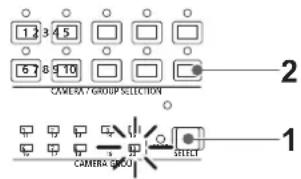
Example: When camera group "10" is selected
When the mode selection button [SELECT] indicator is off, you can press a camera selection button [CAMERA / GROUP SELECTION] to select the remote camera to control.
When a camera selection button is pressed, the indicator of the pressed button turns on and the remote camera is selected.
Also, you can determine the statuses of the remote cameras assigned to camera selection buttons 1 to 10 from the lighting statuses of the indicators (camera status indicators) above the buttons.
● Camera status indicator lighting statuses and remote camera statuses
| Indicator lighting status | Remote camera status | Connection between unit and remote camera |
| Off | The connection type of the corresponding camera number is set to “NON”.Power is not being supplied to the remote camera. | IP connection/serial connection |
| On (orange) | The remote camera is in the standby state.Turn the power on as described in “How to turn on the power of the remote cameras” (page 21). | IP connection/serial connection |
| On (green) | The unit is connected to the remote camera. | IP connection/serial connection |
| On (red) | An alarm is being received from the applicable remote camera. | IP connection/serial connection |
About camera selection buttons and camera status indicator displays
- Camera status indicators
| Lighting state of the indicator | Remote camera state |
| Off Not connected | |
| On (amber) Camera standby | |
| On (green) | ● Camera connected● Multiple AW-RP150s connected to the camera |
- Camera selection buttons
| Lighting state of the indicator | Remote camera state |
| Off Unselected | |
| On (green) G_TALLY ON (camera not selected) | |
| On (red) R_TALLY ON (camera not selected) | |
| On (amber) | Selected● The camera changes to this status if it is a camera with R/G_TALLY ON.● The TALLY of the selected camera is displayed on the LCD panel. |
Displaying and operating the status screen
The status screen is displayed as the initial display when the power of the unit is turned on to start it up.
The status screen displays the following information.
- Camera number
- IRIS, ZOOM, and FOCUS position R/B GAIN R/B PED
M.PED ● Status of allocation to ZOOM/FOCUS on the PAN/TILT lever ● Information about allocations to USER buttons
Operating procedure
1. Display
The status screen is displayed as the initial display when the power of the unit is turned on to start it up.
During operation, the status screen is displayed when all of the menu buttons in the menu operation section are off.
2. Select the remote camera to be controlled with the camera selection buttons [CAMERA / GROUP SELECTION].
The selected camera button lights.
When the camera selection button lights, you can control the remote camera from the unit.


| 1 | Camera name, TALLY information | Displays the camera number, model connected, and the TALLY status.When the connection with the camera is via LAN, up to 10 characters of the name set on the camera can be displayed.Refer to the operating instructions for the camera for camera name settings. |
| 2 | Camera number, lens position | Displays the currently selected camera number, and the status of IRIS, ZOOM, and FOCUS. |
| 3 R/B | GAIN, R/B PED, and M.PED information | Displays the setting values for the R/B GAIN dial, R/B PED dial, and M.PED dial. |
| 4 | Information about dial allocations | Displays the function and setting values allocated to the menu operation dial.You can change the function in “A.KNOB1” to “A.KNOB4” in the “RP SETTING” MAINTENANCE menu. |
| 5 ALARM | Displays alarm information notified from the camera. | |
| 6 ROCKER | Displays the function allocated to the ZOOM/FOCUS rocker on the PAN/TILT lever.SELECTTouch to switch the allocated function (ZOOM/FOCUS).MODEYou can touch this to enable (ENABLE)/disable (DISABLE) the allocated function. | |
| 7 | Camera number, lens position | Displays the currently selected camera number, and the status of IRIS, ZOOM, and FOCUS. |
| 8 ALARM | Displays alarm information notified from the camera. | |
| 9 Information about function assignations | The information about functions assigned to USER1 to 10 is displayed.You can operate (On/Off, etc.) the assigned functions by touching the buttons. | |
Displaying menus and the menu configuration
Use the menu buttons and LCD panel on the unit to operate the menus.
Follow the procedure below to display the menu. The menu is displayed on the LCD panel (A) of the unit.
- Touch panel operations can be performed within the touch operation areas B.

A. LCD panel B. Touch operation areas C. Displays the currently selected camera number and name, and the status of TALLY.
Operating procedure
1. Press the [PAINT] (D), [FUNCTION] (E), [MAINTENANCE] (F), [PMEM/TMEM] (G), or [SYSTEM] (H) button to select the menu group.
The corresponding group appears on the LCD panel (A). (This section describes the [PAINT] group as an example.)
- Pressing a selected button again will turn the menu display off and the status screen is displayed.
For details, refer to "Menu group" (page 39).

D. [PAINT] button E. [FUNCTION] button F. [MAINTENANCE] button G. [PMEM/TMEM] button H. [SYSTEM] button 1. Top section of screen
When a menu is touched, the applicable menu items are displayed in the middle section of the screen.
J. Middle section of screen
Setting items from the menu selected in the top section of the screen are displayed, and by touching the row number of the menu item and using the F1 to F4 dials, you can change the setting values of the applicable column.
2. Touch the screen to select the menu you want to configure.
Select the target menu from the top section of the screen. (This section describes the [SCENE] as an example.)
The setting items appear in the middle section of the screen.
- You can switch the setting menu pages using the page switching buttons (left and right) (K).

K. Page switching buttons (left and right)
- Select the item you want to configure in the middle section of the screen using the cursor movement buttons (L).
- You can also touch the row number (M) to select the items.
- You can switch the setting item pages using the page switching buttons (up and down) (N).
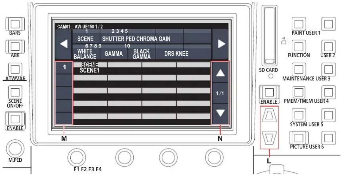
L. Cursor movement buttons M. Row numbers N. Page switching buttons (up and down) 4. Use the menu operation dial (O) to change the setting value.
Turn the dial at the same position as each item in the screen.

O. Touch the row number of the menu item and use the F1 to F4 dials to change the setting values of the applicable column.
To control a remote camera connected via an IP connection from the unit, you need to set the network settings of the unit.
Note
- Correct operation is not possible if the same IP address already exists in the same network.
The message "IP Duplicate" may be displayed during start up, etc., when duplicate IP addresses have been detected.
Set IP addresses that are not duplicates of any existing IP addresses.
Setting the IP address of the unit
1. Press the [SYSTEM] button.
2. Touch "RP IP SET" to display the "IP" item.

- This is set to "192.168.0.9" by default.
3. Use the menu operation dials to set the IP address of the unit to one that is not a duplicate of that of another device.
Enter this in 4 blocks of numerals.
If "UPLOAD" in the fifth row is not executed, the changes are not updated.
- The "IP Duplicate" message is displayed when the connection destination IP address of the remote camera is duplicated, and it cannot be registered.
Refer to the "Settable addresses" (page 31).
Notes
- In order for the setting to take effect, the unit must be restarted. Turn off the unit's power, and then turn it back on.
- Consult the network administrator before setting the IP address.
Setting the subnet mask
1. Press the [SYSTEM] button.
2. Touch "RP IP SET" to display the "SUBNET" item.

● This is set to "255.255.255.0" by default.
3. Press the cursor movement buttons to select "SUBNET".
- You can also select by touching the row number.
4. Use the menu operation dials to set the subnet mask of the unit.
Enter this in 4 blocks of numerals.
If "UPLOAD" in the fifth row is not executed, the changes are not updated.
- "Unavailable Subnetmask setting" is displayed if a value that cannot be set is entered.
Refer to the "Settable addresses" (page 31).
Note
- In order for the setting to take effect, the unit must be restarted. Turn off the unit's power, and then turn it back on.
Setting the default gateway
- Press the [SYSTEM] button.
- Touch "RP IP SET" to display the "GATEWAY" item.

- This is set to "192.168.0.1" by default.
- Press the cursor movement buttons to select "GATEWAY".
- Use the menu operation dials to set the default gateway of the unit.
Enter this in 4 blocks of numerals.
If "UPLOAD" in the fifth row is not executed, the changes are not updated.
Note
- In order for the setting to take effect, the unit must be restarted. Turn off the unit's power, and then turn it back on.
Memo
Settable addresses
- For the IP address, you can set values within the following ranges.
| Block 1: 1 to 223 | Block 2: 0 to 255 |
| Block 3: 0 to 255 | Block 4: 1 to 254 |
However, "127.0.0.1" cannot be set even though it is within the above ranges.
- For the subnet mask, you can set values within the following ranges.
| Block 1: 0 to 255 | Block 2: 0 to 255 |
| Block 3: 0 to 255 | Block 4: 0 to 255 |
However, "0.0.0.0" and "127.0.0.1" cannot be set even though they are within the above ranges.
Displaying the MAC address
- Press the [SYSTEM] button.
- Touch "RP IP SET" to display the "MAC ADDRESS" item.
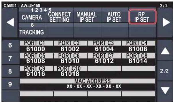
● The MAC address can only be displayed. It cannot be changed.
Setting the reception port numbers
Set the port numbers for receiving camera information update notifications from remote cameras.
Set this when connecting remote cameras via a router.
- Set 10 port numbers because update notifications are received from the remote cameras in the selected camera group.
- Press the [SYSTEM] button.
- Touch "RP IP SET" to display the "PORT C1" to "PORT C10" items.
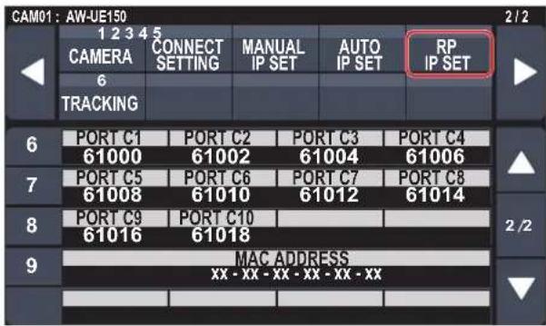
- Use the menu operation dials to set the reception port number for each camera number.
Input range: 61000 to 65535
- "Unavailable Subnetmask setting" is displayed if a port number for a duplicated reception port is entered.
To control remote cameras from the unit and use the function to link the unit, you need to set the connection settings in advance.
There are two ways of configuring the connection settings. You can either configure the settings on the unit or use the setup software to configure the settings.
This section describes how to configure the settings on the unit.
For details on how to use the setup software to configure the settings, refer to "Setup Software" (page 83).
Notes
- All the remote cameras are set to the same IP address when they are shipped from the factory. Therefore, if multiple remote cameras left set to the factory default state are connected with IP connections and then operated from the unit, they will not operate properly.
- When another remote camera that is set to the same IP address as an existing remote camera is to be connected because, for example, the existing remote camera is being replaced, turn off the unit's power before making the connection. When the remote camera is connected without first turning off the unit's power, the remote camera may not operate properly.
Link settings
Selecting one of the camera numbers CAM1 to CAM200 on the unit identifies the remote camera to control. When the remote camera you are attempting to control is connected via an IP connection, you need to set an IP address that is not a duplicate of that of each of the remote cameras and associate each IP address and each camera number on the unit beforehand in order to perform control.
These association settings are referred to as "link settings" in this manual.
Connection destination IP addresses
The IP address for the unit to identify the connection target (remote camera) is referred to as the "connection destination IP address" in this manual.
One connection destination IP address is allocated for each of the remote cameras connected to the unit, from camera number CAM1 to CAM200, for a total of 200 addresses set in the unit.
The connection destination IP address for each camera number can be viewed in [SYSTEM] button > [MANUAL IP SET] menu.
Overview of related menus and operations
[SYSTEM] button > [CONNECT SETTING]
Set the connection type (serial/IP/no connection) for the remote camera to be connected for each camera number.
[SYSTEM] button > [AUTO IP SET]
Use this menu when you want to configure the settings for linking with the remote cameras automatically. (Auto IP setting)
There are the following three operation modes.
| RENEW IP ADR Configures the link settings by the unit renewing the IP addresses set on the remote cameras. |
| KEEP IP ADR Configures the link settings by keeping the IP addresses set on the remote cameras and renewing the connection destination IP addresses set on the unit. |
| ALL CLEAR Initializes the connection destination IP addresses set on the unit. |
[SYSTEM] button > [MANUAL IP SET]
Use this menu when you want to check or manually change the connection destination IP address set for each camera number.
Setting the connection types (serial/IP/no connection) for remote cameras
1. Set the connection types for camera numbers CAM1 to CAM200.
Display the menu items with [SYSTEM] button > [CONNECT SETTING].

2. Set with the F1 dial and F2 dial.
You can specify the camera number (F1 dial) and the connection type (F2 dial) in the first row.
The rows from the second row onward display the connection type for each camera number, and you can set them.
The connection type flashes when the setting is changed, so press the dial to confirm the change.
Serial: Serial connection
LAN: IP connection
NON: No connection (factory default)
The following message appears while the setting is being changed.
● The SERIAL CONT connectors [1] to [5] for serial connections correspond to each of the camera numbers CAM1 to CAM5.
The serial connection "Serial" setting cannot be selected for CAM6 to CAM200.
Note
- When performing the steps described in "auto IP setting" (pages 33 to 37), set the target camera number to "NON".
Setting the IP addresses automatically (auto IP setting)
When "auto IP setting" is executed, the settings for linking between the remote cameras connected within the same subnet as the unit are configured automatically.
The following explanations are split into configuring the settings for the first time (when the remote cameras and switcher are in the factory default state) and introducing additional remote cameras into an environment in which IP connections are already in use.
When configuring the settings for the first time
With the [SYSTEM] button > [AUTO IP SET], set the "AUTO SET" item to "RENEW", then the link is set by executing SETTING in "EXEC". When the "AUTO SET" item is "RENEW", the unit first searches within the same subnet. After this, each detected remote camera is allocated a camera number in order.
At this time, each remote camera IP address is overwritten with the connection destination IP address value set for each camera number in the unit.
Example:
(1) IP addresses set for remote cameras A, B and C (factory default state).
Remote camera A : 192.168.0.10
Remote camera B : 192.168.0.10
Remote camera C : 192.168.0.10
(2) Connection types set on the unit ([SYSTEM] button > [CONNECT SETTING])
CAM1 : NON
CAM2 : NON
CAM3 : NON
(3) Connection destination IP addresses set on the unit ([SYSTEM] button > [MANUAL IP SET])
CAM1:192.168.0.10
CAM2 : 192.168.0.11
CAM3:192.168.0.12
When the "AUTO SET" item is set to "RENEW" in this state, the IP addresses for remote cameras A to C are overwritten with the following values, and links are set with each of camera numbers CAM1 to CAM3.
Remote camera A : 192.168.0.10
Remote camera B : 192.168.0.11
Remote camera C : 192.168.0.12

Memo
The IP address allocated to the camera is the next number from the IP address of this unit.
If the IP address setting for this unit is 192.168.0.9, then allocations start from 192.168.0.10.
![graph TD A["Remote camera A"] -->|192.168.0.10 → 192.168.0.10| B["Unit"] B -->|CAM1| A B -->|CAM2| A B -->|CAM3| C["Remote camera C"] C -->|192.168.0.10 → 192.168.0.12| D["Unit"] D -->|192.168.0.9| B D -->|192.168.0.11| E["Remote camera B"] E -->|192.168.0.10 → 192.168.0.12| F["Unit"]](/content/2026/05/812394/images/2a4b4cfb6be7bcf1c079e2796197f31652b2f86cc96e482b7f76694525df75eb.jpg)
- For the camera numbers for which "auto IP setting" is executed, the connection type becomes "LAN" and the camera numbers are excluded from the setting targets the next time "auto IP setting" is executed.
Note
- Before configuring the settings, check that the connection types of the remote cameras are "NON".
Connection type settings SYSTEM menu → CONNECT SETTING → "CAM1" to "CAM200" items
- Connect the remote cameras and unit to the network within the same subnet.
- Select the SYSTEM menu [AUTO IP SET], turn the F1 dial to set the "AUTO SET" item to "RENEW", then press the F1 dial.

The number of devices currently being managed by the unit (All remote cameras and the newly detected number of devices are displayed in "NEW" and "TOTAL".)
NEW: Newly detected cameras
TOTAL: The number of devices currently being managed by the unit + Number of newly detected devices
- Turn the "EXEC" (F4 dial) to select "SETTING", then press the F4 dial.
"Auto IP setting" starts.
The "AUTO IP SETTING" message is displayed while "auto IP setting" is being performed.
- The "COMPLETE" message is displayed when the entire process is successful.
The remote cameras automatically reboot and restart with the newly configured IP addresses.
The remote cameras can now be operated from the unit.
- The "SET UP ERR" message is displayed when IP address setting fails.
The cause of the problem is likely to be a network malfunction. Check the connection status of the hub and LAN cables, and then retry the "auto IP setting" operation.
When introducing additional remote cameras into an environment in which IP connections are already in use
The settings can be configured using "auto IP setting" even when introducing additional remote cameras into an environment in which IP connections are already in use.
There are the following two methods.
- Automatically changing the IP address set on the additional device to be introduced from the unit
- Leaving the IP addresses of the additional devices to be introduced unchanged and automatically updating the connection destination IP addresses set on the unit
Automatically changing the IP address set on the additional device to be introduced from the unit
By executing "RENEW" in the "AUTO SET" item of the "AUTO IP SET" SYSTEM menu, links are set.
With "RENEW", the unit first searches within the same subnet. Then, links are set between the newly detected remote cameras and camera numbers for which the connection type is set to "NON" on the unit. At that time, the IP addresses of the remote cameras are overwritten with the connection destination IP address values set on the unit.
Example:
(1) Operation is being performed with the three remote cameras A, B and C set to CAM1, CAM2 and CAM3, respectively. (2) The new remote camera D (with the following IP address value) is added.
Remote camera D : 192.168.0.10
(3) Connection types set on the unit ([SYSTEM] button > [CONNECT SETTING])
CAM1 : LAN
CAM2 : LAN
CAM3 : LAN
CAM4 : NON
(4) Connection destination IP address set on the unit ([SYSTEM] button > [MANUAL IP SET])
CAM4:192.168.0.13
When "RENEW" is executed in this state, the IP address of remote camera D is overwritten with the following value, and a link is set to the camera number CAM4.
Remote camera D : 192.168.0.13
![graph TD A["Remote camera D"] -->|192.168.0.10 → 192.168.0.13| B["Remote camera A"] B --> C["Remote camera B"] C --> D["Remote camera C"] D --> E["Connection destination IP address of CAM4"] E --> F["CAM4"]](/content/2026/05/812394/images/1a3fcf2aba6083195afd8c616ce0c13b6c56856f373669abd24a21db1db7c8a6.jpg)
- When you connect a remote camera for which the IP address has been changed using a personal computer or other device after a link was set to the unit with auto IP setting and then execute "RENEW", the same IP address as was set when auto IP setting was executed the first time is set again for the corresponding camera.
- Connect the additional remote cameras to be introduced and the unit to the network within the same subnet.
- Select the "AUTO IP SET" SYSTEM menu, turn the F1 dial to display "RENEW", then press the F1 dial.

The number of devices currently being managed by the unit (All remote cameras and the newly detected number of devices are displayed in "NEW" and "TOTAL".)
NEW : Newly detected cameras
TOTAL : The number of devices currently being managed by the unit + Number of newly detected devices
3. Set "EXEC" (F4 dial) to "SETTING", then press the F4 dial.
"Auto IP setting" starts.
The "AUTO IP SETTING" message is displayed while "auto IP setting" is being performed.
- The "COMPLETE" message is displayed when the entire process is successful.
The remote cameras are automatically rebooted, and they restart with the new IP addresses which were set.
The remote cameras can now be operated from the unit.
- The "SET UP ERR" message is displayed when IP address setting fails.
The cause of the problem is likely to be a network malfunction. Check the connection status of the hub and LAN cables, and then retry the "auto IP setting" operation.
■Leaving the IP addresses of the additional devices to be introduced unchanged and automatically updating the connection destination IP addresses set on the unit
By executing "KEEP" in the "AUTO SET" item of the "AUTO IP SET" SYSTEM menu, links are set.
With "KEEP", the unit first searches within the same subnet.
Then, links are set between the newly detected remote cameras and camera numbers for which the connection type is set to "NON" on the unit.
At that time, the IP addresses of the remote cameras are kept as is and the connection destination IP address values set on the unit are overwritten.
Example:
(1) Operation is being performed with the three remote cameras A, B and C set to CAM1, CAM2 and CAM3, respectively. (2) The new remote camera D (with the following IP address value) is added.
Remote camera D : 192.168.0.20
(3) Connection types set on the unit ([SYSTEM] button > [CONNECT SETTING])
CAM1 : LAN
CAM2 : LAN
CAM3: LAN
CAM4 : NON
(4) Connection destination IP address set on the unit ([SYSTEM] button > [MANUAL IP SET])
CAM4 : 192.168.0.13
When "KEEP" is executed in this state, the IP address of remote camera D is not changed, the connection destination IP address set on the unit is overwritten with the following value, and a link is set to remote camera D.
Connection destination IP address of CAM4: 192.168.0.20
![graph TD A["Remote camera D"] -->|192.168.0.20| B["Cam4"] C["Remote camera A"] -->|192.168.0.20| B D["Remote camera B"] -->|192.168.0.20| B E["Remote camera C"] -->|192.168.0.20| B F["Connection destination IP address of CAM4"] -->|192.168.0.13 → 192.168.0.20| B](/content/2026/05/812394/images/4a86c0cf84d956db033e25ef59507f4d7dc1d9f74863126394a45e429ad314ee.jpg)
- If camera numbers for which the connection type is set to other than "Serial" include a camera number for which the connection destination IP address is set to the same value as the IP address of a detected remote camera, the connection destination IP address set on the unit is not updated. The connection destination IP address is kept as is and a link is set for the corresponding camera number and remote camera.
Note
- Set the subnet mask of the unit and remote camera to the same value. If the subnet masks are different, no operations using the network will be possible.
- Connect the additional remote cameras to be introduced and the unit to the network within the same subnet.
- Select the "AUTO IP SET" SYSTEM menu, turn the F1 dial to display "KEEP", then press the F1 dial.

The number of devices currently being managed by the unit (All remote cameras and the newly detected number of devices are displayed in "NEW" and "TOTAL".)
NEW : Newly detected cameras
TOTAL : The number of devices currently being managed by the unit + Number of newly detected devices
- Set "EXEC" (F4 dial) to "SETTING", then press the F4 dial.
"Auto IP setting" starts.
The "AUTO IP SETTING" message is displayed while "auto IP setting" is being performed.
- The "COMPLETE" message is displayed when the entire process is successful. The remote cameras can now be operated from the unit.
- The "IP Duplicate!" message is displayed when the IP address of an already running device and the IP address of a remote camera being added are the same, and the link setting is not made. Check the IP addresses of the additional remote cameras to be introduced, and then perform the "auto IP setting" operation again.
- The "SET UP ERR" message is displayed when IP address setting fails.
The cause of the problem is likely to be a network malfunction. Check the connection status of the hub and LAN cables, and then retry the “auto IP setting” operation.
Memo
Connection device detection
- When the number of new devices detected by "RENEW" or "KEEP" exceeds the number of devices that can be registered (200 remote cameras), "C/S OVER!" appears. Auto IP setting can be executed even in this state, but IP addresses will be set only for the number of devices that can be registered.
- The unit may not be able to detect all of the remote cameras when, for example, multiple remote cameras are started at the same time. In this case, select "RETRY" in the "EXEC" item and press the F4 dial to retry.
- If the number of newly detected devices does not match the number of devices that are to actually be set, such as if the power of the remote camera was not on, etc., solve the problem, then select "RETRY" in the "EXEC" item and press the F4 dial to retry.
Notes
- When adding another remote camera controller (AW-RP150 [this unit]), set an IP address that is not a duplicate of any IP address within the same network before making the connection.
- Execute "auto IP setting" when devices not applicable for auto IP setting (devices other than the remote cameras) are in a non-operation state. After executing "auto IP setting", connect these devices after checking that there is no duplicate IP address within the same network.
Manually setting the connection destination IP addresses (remote cameras) and port number
Use the following procedure when connecting (via a router) remote cameras whose IP addresses cannot be set by following the steps in "auto IP setting" or to manually configure the link settings for the unit and remote cameras.
1. Select the "MANUAL IP SET" SYSTEM menu, turn the F1 dial to display the camera number whose settings you want to change.

2. Set the IP address (remote camera) and PORT number.
Operate "CAM SEL" in the first row to select the camera number for which you want to set the IP address that will be the connection destination.
The rows from the second and so on display the existing IP address and PORT number for each corresponding camera number.
Set the connection destination IP address in "CAM IP" in the second row.
The screen is divided into 4 blocks and these are set using the F1 to F4 dials.
Set the connection destination PORT number in "PORT" in the third row using the F1 dial.
Execute "UPLOAD" after setting. The set IP address and PORT number settings are not updated if "UPLOAD" is not executed.
Setting is also possible for camera numbers whose connection type is "NON" or "Serial" in [SYSTEM] button > [CONNECT SETTING].
● This is set to the following value by default.
CAM1: 192.168.0.10
↓ CAM200 : 192.168.0.209
- When the IP address of the connection destination is changed, checks are made for duplicate IP addresses set in other items.
The "IP Duplicate!" message is displayed when the IP address is duplicated.
- The "Unavailable network setting" message is displayed when the PORT number specified cannot be set.
■ Settable port numbers
You can set a value within the range of 1 to 65535.
However, the following values cannot be set even though they are within this range.
20, 21, 23, 25, 42, 53, 67, 68, 69, 110, 123, 161, 162, 995, 10669, 10670
Note
- The IP addresses set on the remote cameras are not changed by this operation.
Initializing the connection destination IP addresses set on the unit
Use the following procedure to initialize the connection types and connection destination IP addresses set on the unit.
1. Select the "RP INIT" MAINTENANCE menu and select the "INIT ALL".

2. Press the F1 dial to execute initialization.
The settings for connecting with the remote cameras are initialized.
Memo
- When the connection type is set to "LAN", it is changed to "NON". When the connection type is set to "Serial", it is not changed.
- If the IP address of the unit is changed, the connection destination IP addresses are changed automatically.
- IP addresses after the IP address of the unit are set for the camera numbers in ascending order.
Menu group
| PAINTSCENE | ⇒ "SCENE" (page 40) | |
| SHUTTER | ⇒ "SHUTTER" (page 41) | |
| PED | ⇒ "PED" (page 41) | |
| CHROMA | ⇒ "CHROMA" (page 42) | |
| GAIN | ⇒ "GAIN" (page 42) | |
| WHITE BALANCE | ⇒ "WHITE BALANCE" (page 43) | |
| GAMMA | ⇒ "GAMMA" (page 44) | |
| BLACK GAMMA | ⇒ "BLACK GAMMA" (page 44) | |
| DRS | ⇒ "DRS" (page 45) | |
| KNEE | ⇒ "KNEE" (page 45) | |
| WHITE CLIP | ⇒ "WHITE CLIP" (page 46) | |
| DTL | ⇒ "DTL" (page 46) | |
| DC DTL | ⇒ "DC DTL" (page 47) | |
| MATRIX | ⇒ "MATRIX" (page 47) | |
| COLOR CORRE | ⇒ "COLOR CORRE" (page 48) | |
| DNR | ⇒ "DNR" (page 49) | |
| BRIGHTNESS | ⇒ "BRIGHTNESS" (page 50) | |
| FUNCTION USER ASSIGN | ⇒ "USER ASSIGN" (page 51) | |
| CAMERA INFO | ⇒ "CAMERA INFO" (page 52) | |
| PTZ INFO1 | ⇒ "PTZ INFO1" (page 53) | |
| PTZ INFO2 | ⇒ "PTZ INFO2" (page 54) | |
| HOUSING INFO | ⇒ "HOUSING INFO" (page 55) | |
| CROP | ⇒ "CROP" (page 56) | |
| MAINTENANCECAMERA MENU OP | ⇒ "CAMERA MENU OP" (page 57) | |
| RP SETTING | ||
| FILES | ||
| RP INIT | ||
| RP VERSION | ||
| GPI TALLY | ||
| GPIO CAM SEL | ||
| GPO CAM.G | ||
| GPI PMEM | ||
| GPI PMEM.G | ||
| SYSTEM CAMERA | ⇒ "CAMERA" (page 69) | |
| CONNECT SETTING | ⇒ "CONNECT SETTING" (page 70) | |
| MANUAL IP SET | ⇒ "MANUAL IP SET" (page 71) | |
| AUTO IP SET | ⇒ "AUTO IP SET" (page 72) | |
| RP IP SET | ⇒ "RP IP SET" (page 73) | |
| TRACKING | ⇒ "TRACKING" (page 74) | |
| PMEM/TMEM PMEM LIST | ⇒ "PMEM LIST" (page 76) | |
| PMEM DIRECT | ⇒ "PMEM DIRECT" (page 77) | |
| PMEM STORE | ⇒ "PMEM STORE" (page 78) | |
| PMEM DEL | ⇒ "PMEM DEL" (page 79) | |
| TMEM | ⇒ "TMEM" (page 80) | |
| SETTING | ⇒ "SETTING" (page 81) | |
PAINT
| ⇒ "SCENE" (page 40) |
| ⇒ "SHUTTER" (page 41) |
| ⇒ "PED" (page 41) |
| ⇒ "CHROMA" (page 42) |
| ⇒ "GAIN" (page 42) |
| ⇒ "WHITE BALANCE" (page 43) |
| ⇒ "GAMMA" (page 44) |
| ⇒ "BLACK GAMMA" (page 44) |
| ⇒ "DRS" (page 45) |
| ⇒ "KNEE" (page 45) |
| ⇒ "WHITE CLIP" (page 46) |
| ⇒ "DTL" (page 46) |
| ⇒ "DC DTL" (page 47) |
| ⇒ "MATRIX" (page 47) |
| ⇒ "COLOR CORRE" (page 48) |
| ⇒ "DNR" (page 49) |
| ⇒ "BRIGHTNESS" (page 50) |
SCENE
● The setting values will vary depending on the connected camera.

| Item Setting details | |
| SCENE | Selected here is the shooting mode that matches the shooting situation. |
SHUTTER
- The setting values will vary depending on the connected camera.

| Item Setting details | |
| MODE Select for camera | shutter mode. |
| SPEED Select the shutter speed for the camera. | |
| ELC LIMIT Set the maximum shutter level when ELC is operating. | |
PED
● The setting values will vary depending on the connected camera.

| Item Setting details | |
| R PED | Adjust the pedestal of the R channel. |
| G PED | Adjust the pedestal of the G channel. |
| B PED | Adjust the pedestal of the B channel. |
| M.PED | This item is used to adjust the black level (adjust the pedestal). |
| OFFSET | Set the pedestal level of the Rch, Gch, and Bch when the auto black balance has been adjusted. |
CHROMA
- The setting values will vary depending on the connected camera.

| Item Setting details |
| LEVEL Set here the color intensity (chroma level) of the images. |
| PHASE Make fine adjustments to the hue of the colors in the images. |
GAIN
● The setting values will vary depending on the connected camera.

| Item Setting details | |
| SUPER GAIN | Set the mode for super gain (increased sensitivity). |
| GAIN | The image gain is adjusted here.In locations which are too dark, adjust the gain upward; conversely, in locations which are too bright, adjust it downward. |
| AGC MAX When [Auto] is selected as the [Gain] setting, the maximum gain-up amount can be set. | |
WHITE BALANCE
● The setting values will vary depending on the connected camera.

| Item Setting details | |
| MODE Set the white balance mode. Select the mode when the coloring is not natural because of the nature of the light source or other factors. If the white color serving as the reference can be recognized, subjects can be shot with natural coloring. | |
| COLOR TMP Specify a color temperature between 2000K and 15000K. | |
| R GAIN Adjust the gain of the R channel. | |
| B GAIN Adjust the gain of the B channel. | |
| OFFSET | When auto white balance is performed by setting [White Balance Mode] to [AWB A] or [AWB B], set the values for Rch gain and Bch gain. |
| A.SPEED | Set the control speed of the ATW function. |
| A.TARGET R | Make fine adjustments to the Rch output when converging with the auto tracking white balance operation. |
| A.TARGET B | Make fine adjustments to the Bch output when converging with the auto tracking white balance operation. |
GAMMA
- The setting values will vary depending on the connected camera.

| Item Setting details | |
| MODE Select the type of | gamma curve. |
| COLOR TMP Adjust the | gamma correction level.Specifying smaller values results in a gentler gamma curve for the slope of low-brightness areas and sharper contrast.Specifying larger values results in an expanded gradient for dark areas and produces brighter images. The gamma curve for lowbrightness areas will be steeper, and contrast will be softer. |
| F-REC.D | When “FILM-REC” is selected in [MODE], you can adjust the dynamic range. |
| F-REC STR | When “FILM-REC” is selected in [MODE], you can adjust the black stretch. |
| V-REC SLP When “VIDEO-REC” is selected in [MODE], you can adjust the knee slope. | |
| V-REC.P | When “VIDEO-REC” is selected in [MODE], you can adjust the knee point. |
BLACK GAMMA
● The setting values will vary depending on the connected camera.

| Item Setting details | |
| B.GAMMA | Set the gamma curve for dark areas. |
| RANGE | Set the maximum level of compression/expansion. |
DRS
● The setting values will vary depending on the connected camera.

| Item Setting details | |
| DRS | Set the DRS function which performs correction when video with high light/dark contrast is displayed. |
KNEE
● The setting values will vary depending on the connected camera.

| Item Setting details | |
| MODE Set the operating | mode for gradation compression (knee). |
| A.KNEE RES | Set the speed of the auto knee response.The response speed increases the lower the setting value. |
| POINT | Set the compression level (knee point) position for high-brightness video signals. |
| SLOPE | Set the knee slope. |
| HLG K.SW | Enable (on) or disable (off) the operation of the HLG knee. |
| HLG K.PNT | Set the position of the HLG knee point. |
| HLG K.SLP | Set the incline of the HLG knee. |
WHITE CLIP
- The setting values will vary depending on the connected camera.

| Item Setting details | |
| CLIP Enable (on) or disable (off) the white clip function. | |
| LEVEL Set the white clip level. |
DTL
● The setting values will vary depending on the connected camera.
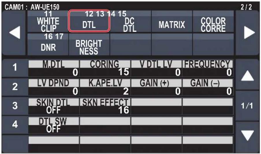
| Item Setting details | |
| M.DTL Adjust the contour correction level (master). | |
| CORING Set the level of the signal (including noise) which makes the detail effect not work. | |
| V DTL LV Adjust the vertical contour correction level. | |
| FREQUENCY This is selected to set the boost frequency for Detail. | |
| LV DPND | When the detail of bright signals are emphasized, the detail of dark parts are compressed.The larger the value, the more detail of bright parts is compressed. |
| K.APE.LV | Set the detail level of very bright parts. |
| GAIN(+) | Set the detail level of the plus direction (direction to be made brighter). |
| GAIN(-) | Set the detail level of the minus direction (direction to be made darker). |
| SKIN DTL | This function smooths skin and produces a more beautiful image. |
| SKN EFFECT | The skin of human subjects appears smoother the larger the setting value of Skin Detail. |
| DTL SW | Enable (on) or disable (off) the turn outline (i.e., image sharpness) adjustment. |
DC DTL
● The setting values will vary depending on the connected camera.
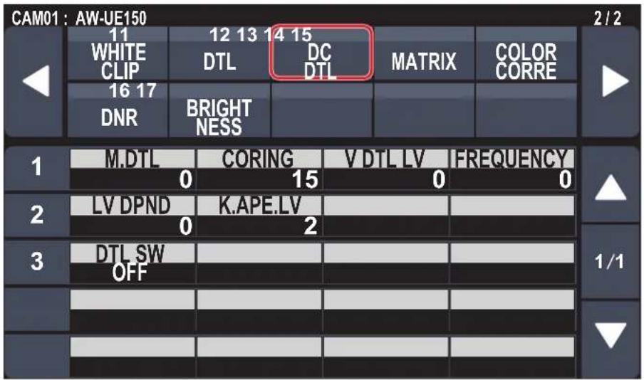
| Item Setting details | |
| M.DTL Adjust the contour correction level (master) for images down-converted from 4K to HD. | |
| CORING | Set the level of the signal (including noise) which makes the detail effect not work for images down-converted from 4K to HD. |
| V DTL LV | Adjust the contour correction level in the vertical direction for images down-converted from 4K to HD. |
| FREQUENCY Set the boost frequency of detail for images down-converted from 4K to HD.By setting a high frequency, even finer detail effects are attached to the subject. | |
| LV DPND | The larger the setting for images down-converted from 4K to HD, the more detail of bright parts is compressed. |
| K.APE.LV Set the detail level of very bright parts in images down-converted from 4K to HD. | |
| DTL SW | Enable (on) or disable (off) the contour (sharpness of images) adjustment of images down-converted from 4K to HD. |
■MATRIX
● The setting values will vary depending on the connected camera.

| Item Setting details | |
| TYPE | Select the type of color matrix. |
| R-G, R-B, G-R, G-B, B-R, B-G | Adjust the color to between -63 to +63 for each axis direction. |
COLOR CORRE
● The setting values will vary depending on the connected camera.
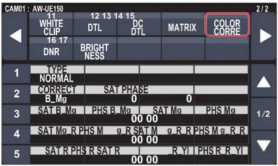

| Item | Setting details |
| TYPE | Select the type of color matrix. |
| CORRECT | Adjust the saturation and hue. |
| SAT | Adjust the saturation for each color. |
| PHASE Adjust the hue for each color. | |
| SAT B_Mg | Adjust the saturation of the color between blue and magenta. |
| PHS B_Mg | Adjust the hue of the color between blue and magenta. |
| SAT Mg | Adjust the saturation of magenta. |
| PHS Mg | Adjust the hue of magenta. |
| SAT Mg_R | Adjust the saturation of the color between magenta and red. |
| PHS Mg_R | Adjust the hue of the color between magenta and red. |
| SAT Mg_R_R | Adjust the saturation of the color with a ratio of 1:3 magenta and red. |
| PHS Mg_R_R | Adjust the hue of the color with a ratio of 1:3 magenta and red. |
| SAT R | Adjust the saturation of red. |
| PHS R | Adjust the hue of red. |
| SAT R_R_YI | Adjust the saturation of the color with a ratio of 3:1 red and yellow. |
| PHS R_R_YI | Adjust the hue of the color with a ratio of 3:1 red and yellow. |
| SAT R_YI | Adjust the saturation of the color between red and yellow. |
| PHS R_YI | Adjust the hue of the color between red and yellow. |
| SAT R_YI_YI | Adjust the saturation of the color with a ratio of 1:3 red and yellow. |
| PHS R_YI_YI | Adjust the hue of the color with a ratio of 1:3 red and yellow. |
| SAT YI | Adjust the saturation of yellow. |
| PHS YI | Adjust the hue of yellow. |
| Item Setting details | |
| SAT YI_YI_G Adjust the | saturation of the color with a ratio of 3:1 yellow and green. |
| PHS YI_YI_G Adjust the | hue of the color with a ratio of 3:1 yellow and green. |
| SAT YI_G Adjust the saturation of the color between yellow and green. | |
| PHS YI_G Adjust the hue of the color between yellow and green. | |
| SAT G Adjust the saturation of green. | |
| PHS G Adjust the hue of green. | |
| SAT G_Cy Adjust the saturation of the color between green and cyan. | |
| PHS G_Cy Adjust the hue of the color between green and cyan. | |
| SAT Cy Adjust the saturation of cyan. | |
| PHS Cy Adjust the hue of cyan. | |
| SAT Cy_B Adjust the saturation of the color between cyan and blue. | |
| PHS Cy_B Adjust the hue of the color between cyan and blue. | |
| SAT B Adjust the saturation of blue. | |
| PHS B Adjust the hue of blue. | |
DNR
● The setting values will vary depending on the connected camera.

| Item Setting details | |
| DNR | Set the digital noise reduction level for outputting bright, clear images without noise, even at night and low-light conditions. |
BRIGHTNESS
● The setting values will vary depending on the connected camera.

| Item Setting details | |
| PCTR LV | This menu item is selected to set the target picture level for automatic exposure compensation. |
| FRM MIX Select for frame | addition (gain-up using sensor storage) amount.When frame addition is performed, it will appear as if the images are missing some frames. |
| DAY/NIGHT | Switch between standard shooting and night-vision shooting (shooting with infrared light). |
FUNCTION
| ⇒ "USER ASSIGN" (page 51) |
| ⇒ "CAMERA INFO" (page 52) |
| ⇒ "PTZ INFO1" (page 53) |
| ⇒ "PTZ INFO2" (page 54) |
| ⇒ "HOUSING INFO" (page 55) |
| ⇒ "CROP" (page 56) |
■USER ASSIGN
- The setting values will vary depending on the connected camera.

| Item Initial setting Setting details | ||
| USER1*1 | SHOOTING It is possible to allocate the following functions to the user buttons. | |
| USER2*1 | ND1 POWER OFF:Power off function | HEATER:Heater On/Off function (for a future expansion feature) |
| USER3*1 | ND2 | FAN:Fan On/Off function |
| USER4*1 | ND3 | WASHER:Washer On/Off function (for a future expansion feature) |
| USER5*1 | ND4 | CAM LCK:CAM LOCK setting/cancel function |
| USER6*1 | D.EXT | TRCKING:Tracking On/Off function |
| USER7*1 | D.ZOOM | TR CNCT:TR CONNECT On/Off function |
| USER8*1 | FREEZE.D | ROCKER:ZOOM/FOCUS rocker operation mode (zoom/focus)switching function |
| USER9*1 | CROP SW | SCENE1, SCENE2, SCENE3, SCENE4:SCENE1 to SCENE4 allocation |
| USER10*1 | CAM LCK | SHOOTING:Shooting mode (NORMAL/H.SENSE) function |
| CAM MENU:Menu On/Off function for connected camera | ||
| PMEM1 to PMEM20:Preset memory 1 to 20 selection | ||
*1: This item is saved to the memory card by MAINTENANCE > RP SETTING > DATA SAVE.
■CAMERA INFO
- The setting values will vary depending on the connected camera.
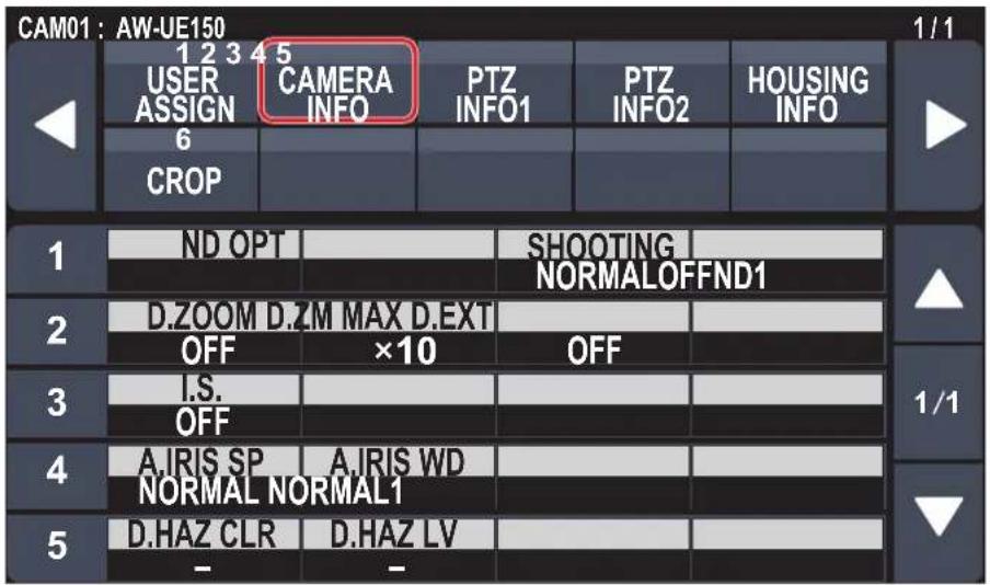
| Item Setting details | |
| ND Set the ND filter. | |
| OPT | Switch between standard shooting mode and night mode. |
| SHOOTING | Select the optimal shooting mode for the shooting environment.NORMAL:Select to shoot in environments where the brightness level is normal.H.SENSE:Select to perform high-sensitivity shooting. (It is suitable for shooting in dark environments.) |
| D.ZOOM | Enable (on) or disable (off) the digital zoom function. |
| D.ZM MAX | Set the maximum digital zoom magnification. |
| D.EXT | Select the digital extender function. |
| I.S. | Select the image stabilization mode. |
| A.IRIS SP | Set the control speed of the auto iris function. |
| A.IRIS WD | Select the detection window for the auto iris. |
| D.HAZ CLR | (For a future expansion feature) |
| D.HAZ LV | (For a future expansion feature) |
■PTZ INFO1
● The setting values will vary depending on the connected camera.
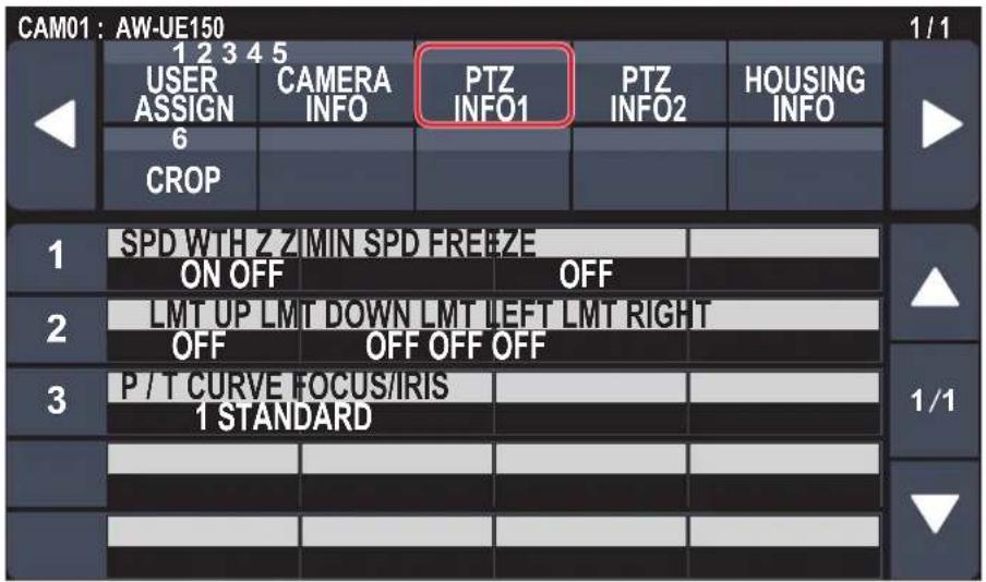
| Item Setting details | |
| SPD WTH Z | Enable (on) or disable (off) the function used to adjust the pan-tilt adjustment speed in conjunction with the zoom magnification.When [ON] is set, the panning and tilting operations will become slower in the zoom status. |
| Z MIN SPD*1 | Calibrate the amount of zoom control sent from the unit so that lens zooming starts smoothly when the ZOOM button is pressed in slowly.Watch the images on the monitor to see if lens zooming starts smoothly when the ZOOM button is pressed in slowly.Calibration starts at “1”, the least amount, to “8”, the most.There is no calibration when [OFF] is selected. |
| FREEZE | Enable (on) or disable (off) the function for freezing images during preset playback.When this is set to [ON], preset playback is performed with a still of the image immediately preceding the start of preset playback being output. The image freeze is released when preset playback is finished. |
| LMT UP | You can set the limiter of the remote camera in the direction of the upper limit from this unit. |
| LMT DOWN | You can set the limiter of the remote camera in the direction of the lower limit from this unit. |
| LMT LEFT | You can set the limiter of the remote camera in the direction of the left limit from this unit. |
| LMT RIGHT | You can set the limiter of the remote camera in the direction of the right limit from this unit. |
| P/T CURVE*1 | You can adjust the relationship between the angle and operation speed when the PAN/TILT lever is tilted.Operating speed |
| FOCUS/IRIS*1 | You can switch the operations of the FOCUS dial and the IRIS dial.EXCHANGE:Switches the operations of the FOCUS dial and the IRIS dial.The operations of the auto focus button and the auto iris button are also switched when [EXCHANGE] is selected.The one-touch auto focus button is disabled.Operation of the FOCUS SPEED dial is disabled.Speed is fixed to the setting it was at the time the setting is changed to [EXCHANGE].STANDARD:Reverts the operations of the FOCUS dial and the IRIS dial. |
*1: This item is saved to the memory card by MAINTENANCE > RP SETTING > DATA SAVE.
■PTZ INFO2
● The setting values will vary depending on the connected camera.

| Item Setting details | |
| CAM SEL Settings can be made for rows from the second and so on for the selected camera number. | |
| PAN DIR Set the operating direction for the remote camera with the pan operation.NORMAL:When the PAN/TILT lever is tilted to the left, the remote camera moves to the left, and when tilted to the right it moves to the right.REVERSE:Reverses the direction of operation of NORMAL. | |
| TILT DIR | Set the operating direction for the remote camera with the tilt operation.NORMAL:When the PAN/TILT lever is tilted away, the remote camera moves up, and when tilted towards the user it moves down.REVERSE:Reverses the direction of operation of NORMAL. |
| ZOOM DIR Set the operating direction for the remote camera with the zoom operation.NORMAL:When the TELE side of the ZOOM button is pressed, the lens moves towards the telephoto end, and when WIDE is pressed it moves towards the wide-angle end.REVERSE:Reverses the direction of operation of NORMAL. | |
| FOCUS DIR | Set the operating direction for the remote camera with the focus operation.NORMAL:When the FOCUS dial is turned to the right, the focus moves to the far end, and when turned to the left, it moves to the near end.REVERSE:Reverses the direction of operation of NORMAL. |
| IRIS DIR | Set the operating direction for the remote camera with the iris operation.NORMAL:When the IRIS dial is turned to the right it moves in the open direction, and when it is turned to the left it moves in the close direction.REVERSE:Reverses the direction of operation of NORMAL. |
■HOUSING INFO
● The setting values will vary depending on the connected camera.

| Item Setting details | |
| FAN Set the cooling fan operation. | |
| HEATER Set the heater operation. (For a future expansion feature) | |
| DEFRSTER Set the defroster device operation. (For a future expansion feature) | |
| WIPER | Set the wiper operation. (For a future expansion feature) |
| WASHER | Clean the lens by spraying washer fluid on to it. (For a future expansion feature)If you select [YES], the camera head moves to the position of the washer nozzle, washer fluid is sprayed for a specific duration, and the camera head returns to the original position.The wiper also operates momentarily during cleaning. |
● The setting values will vary depending on the connected camera.

| Item Setting details | |
| SW | Enable (on) or disable (off) the crop function which crops UHD (3840×2160) images to FHD (1920×1080) images. |
| ADJUST Make selections for the crop frame to adjust positioning. | |
| H POS | Make settings for the position in the horizontal direction for the crop frame specified in [ADJUST].0 is the left edge and 1920 is the right edge. |
| V POS | Make settings for the position in the vertical direction for the crop frame specified in [ADJUST].0 is the upper edge and 1080 is the lower edge. |
| OUT | Make the settings for the crop frame for images output from the 3G SDI OUT terminal and IP. |
| MARKER | Make the settings for the crop frame displayed for images output from the MONI OUT terminal. |

MAINTENANCE
| ⇒ "CAMERA MENU OP" (page 57) |
| ⇒ "RP SETTING" (page 58) |
| ⇒ "FILES" (page 60) |
| ⇒ "RP INIT" (page 61) |
| ⇒ "RP VERSION" (page 61) |
| ⇒ "GPI TALLY" (page 62) |
| ⇒ "GPIO CAM SEL" (page 63) |
| ⇒ "GPO CAM.G" (page 65) |
| ⇒ "GPI PMEM" (page 66) |
| ⇒ "GPI PMEM.G" (page 67) |
■CAMERA MENU OP
● The setting values will vary depending on the connected camera.

____ indicates factory default settings.
| Item Setting value Setting details | ||
| MENU | OFFON | Turns the menu on or off. |
| CURSOR – | Moves the menu cursor | or changes setting values. |
| EXECUTE | – | Executes the selected process. |
■RP SETTING
● The setting values will vary depending on the connected camera.

indicates factory default settings.
| Item Setting value Setting details | ||
| A.KNOB1*1 | GAIN SHTER SPD SCENE G PED COLOR TMP B.GAMMA M.DTL DC M.DTL | Set the functions allocated to the F1 to F4 dials when in the status screen. GAIN: Make gain settings. SHTER SPD: Make shutter speed settings. The setting becomes step shutter (the steps can be changed) or sync shutter (the setting can be changed continuously) in accordance with the shutter speed setting of the camera. SCENE: You can switch the scene mode. G PED: Make G PED settings. COLOR TMP: Make color temperature settings. B.GAMMA: Make black gamma settings. M.DTL: Make settings for the M.DTL item in the DTL menu. DC M.DTL: Make settings for the M.DTL item in the DC DTL menu. |
| A.KNOB2*1 | GAIN SHTER SPD SCENE G PED COLOR TMP B.GAMMA M.DTL DC M.DTL | |
| A.KNOB3*1 | GAIN SHTER SPD SCENE G PED COLOR TMP B.GAMMA M.DTL DC M.DTL | |
| A.KNOB4*1 | GAIN SHTER SPD SCENE G PED COLOR TMP B.GAMMA M.DTL DC M.DTL | |
| Z/F RCKR*1 | ZOOM FOCUS | Allocate either zoom or focus to the ZOOM/FOCUS rocker on the PAN/TILT lever. |
| ROCKER MD*1 | ENABLE DISABLE | Enable (ENABLE) or disable (DISABLE) the function allocated to the ZOOM/FOCUS rocker on the PAN/TILT lever. |
| START MD*1 | STATUS PMEM | Set the screen shown initially on the LCD panel when starting up. STATUS: Displays the status screen. PMEM: Displays the PMEM/TMEM menu screen (PMEM LIST). |
| GPIO MD*1 | MODE1 MODE2 | You can select the DSUB1 and DSUB2 control. For details, refer to “GPIO MODE: MODE1” (page 94) to “GPIO MODE: MODE2” (page 95). |
| LCD BRI*1 | 1 : 10 | Sets the brightness of the LCD panel. |
*1: This item is saved to the memory card by MAINTENANCE > RP SETTING > DATA SAVE.
| Item Setting value Setting details | ||
| LED BRI 1 | 15 | Set the brightness of the panel buttons. |
| BUZZER*1 | OFFON | Enable (on) or disable (off) the buzzer (beep). |
| DATA SAVE | NO?YES? | Save the unit's setting information.● After starting this process, do not turn off the unit or remove memory card until the process is complete. |
| DATA LOAD | NO?YES?YES(+NW)? | Load the unit's setting information.The screen switches to the one for selecting files when you select "YES?".Turn the F1 dial to select the file, then press the F1 dial to load it.YES?:Only load setting values that do not include those related to network settings.YES(+NW)?:Load setting values including those related to network settings.● After starting this process, do not turn off the unit or remove memory card until the process is complete. |
| CARD FRMT | NO?YES? | Format the memory card. |
*1: This item is saved to the memory card by MAINTENANCE > RP SETTING > DATA SAVE.
FILES
● The setting values will vary depending on the connected camera.

| Item Setting details | |
| MODE | Select whether to save the connected camera's setting data to the memory card (STORE), or to load it from the memory card (LOAD).Select "FORMAT" to format the memory card.When [MODE] is "LOAD"[SELECT]: CAMERA ALL, SCENE[FILE]: SCENE1, SCENE2, SCENE3, SCENE4However, this is available only when "SCENE" is selected in [SELECT].When [MODE] is "STORE"[SELECT]: CAMERA ALL, SCENE[FILE]: SCENE1, SCENE2, SCENE3, SCENE4However, this is available only when "SCENE" is selected in [SELECT].When [MODE] is "FORMAT"[SELECT]: ---[FILE]: --- |
| SELECT | Select "CAMERAALL" (camera settings) or "SCENE" (SCENE data). |
| FILE | When [MODE] is "STORE"Select the data to store from SCENE1, SCENE2, SCENE3, or SCENE4.However, this is available only when "SCENE" is selected in [SELECT].When [MODE] is "LOAD"Select the data to load from SCENE1, SCENE2, SCENE3, or SCENE4.However, this is available only when "SCENE" is selected in [SELECT]. |
| EXECUTE When [MODE] is set to "LOAD"Load the file.The screen switches to the one for selecting files when you select "YES?".Turn the F1 dial to select the file, then press the F1 dial to load it.When [MODE] is set to "STORE"Save the file.When [MODE] is "FORMAT"Format the memory card. | |
■RP INIT
● The setting values will vary depending on the connected camera.

indicates factory default settings.
| Item Setting value Setting details | ||
| INIT ALL | NO?YES? | Return all settings managed by this unit, including network settings, to the factory default conditions. |
| INIT | NO?YES? | Return all settings managed by this unit, excluding network settings, to the factory default conditions. |
■RP VERSION
● The setting values will vary depending on the connected camera.

indicates factory default settings.
| Item Setting value Setting details | ||
| UPGRADE | NO?YES? | Updates the software of the unit.After starting this process, do not turn off the unit or remove memory card until the process is complete. |
| SYSTEM VERSION – Displays the system version for the unit. | ||
| SOFT VERSION – Displays the software version. | ||
| FPGA VERSION | – Displays the FPGA version. | |
GPI TALLY
● The setting values will vary depending on the connected camera.

indicates factory default settings.
| Item Setting value Setting details | ||
| TALLY OUT w1 | OFFON | Set whether to send a TALLY notification to the camera if TALLY is input through the port of the TALLY/GPIO 1 connector.ON: NotifyOFF: Do not notify |
| TALLY1 w1 | CAM1⋮CAM200 | Select the camera to send the TALLY notification to when there is an R_TALLY_1 or G_TALLY_1 input through the port of the TALLY/GPIO 1 connector. |
| TALLY2 w1 | CAM1CAM2⋮CAM200 | Select the camera to send the TALLY notification to when there is an R_TALLY_2 or G_TALLY_2 input through the port of the TALLY/GPIO 1 connector. |
| TALLY3 w1 | CAM1⋮CAM3⋮CAM200 | Select the camera to send the TALLY notification to when there is an R_TALLY_3 or G_TALLY_3 input through the port of the TALLY/GPIO 1 connector. |
| TALLY4 w1 | CAM1⋮CAM4⋮CAM200 | Select the camera to send the TALLY notification to when there is an R_TALLY_4 or G_TALLY_4 input through the port of the TALLY/GPIO 1 connector. |
| TALLY5 w1 | CAM1⋮CAM5⋮CAM200 | Select the camera to send the TALLY notification to when there is an R_TALLY_5 or G_TALLY_5 input through the port of the TALLY/GPIO 1 connector. |
| TALLY6 w1 | CAM1⋮CAM6⋮CAM200 | Select the camera to send the TALLY notification to when there is an R_TALLY_6 or G_TALLY_6 input through the port of the TALLY/GPIO 1 connector. |
| TALLY7 w1 | CAM1⋮CAM7⋮CAM200 | Select the camera to send the TALLY notification to when there is an R_TALLY_7 or G_TALLY_7 input through the port of the TALLY/GPIO 1 connector. |
| TALLY8 w1 | CAM1⋮CAM8⋮CAM200 | Select the camera to send the TALLY notification to when there is an R_TALLY_8 or G_TALLY_8 input through the port of the TALLY/GPIO 1 connector. |
| TALLY9 w1 | CAM1⋮CAM9⋮CAM200 | Select the camera to send the TALLY notification to when there is an R_TALLY_9 or G_TALLY_9 input through the port of the TALLY/GPIO 1 connector. |
*1: This item is saved to the memory card by MAINTENANCE > RP SETTING > DATA SAVE.
| Item Setting value Setting details | ||
| TALLY10*1 | CAM1 CAM10 CAM200 | Select the camera to send the TALLY notification to when there is an R_TALLY_10 or G_TALLY_10 input through the port of the TALLY/GPIO 1 connector. |
*1: This item is saved to the memory card by MAINTENANCE > RP SETTING > DATA SAVE.
Note
The TALLY notification is sent if there are applicable cameras in the currently selected camera group. Cameras are not notified even if there is TALLY input for CAMERA groups that are not currently selected.
■GPIO CAM SEL
● The setting values will vary depending on the connected camera.


____ indicates factory default settings.
| Item Setting value Setting details | ||
| IN1*1 | CAM1⋮CAM200 | Select the camera to be switched when there is CAMERA_SELECT_IN1 input through the port of the GPIO 2 connector. |
| IN2*1 | CAM1CAM2⋮CAM200 | Select the camera to be switched when there is CAMERA_SELECT_IN2 input through the port of the GPIO 2 connector. |
| IN3*1 | CAM1⋮CAM3⋮CAM200 | Select the camera to be switched when there is CAMERA_SELECT_IN3 input through the port of the GPIO 2 connector. |
*1: This item is saved to the memory card by MAINTENANCE > RP SETTING > DATA SAVE.
| Item Setting value Setting details | ||
| IN4*1 | CAM1 CAM4 CAM200 | Select the camera to be switched when there is CAMERA_SELECT_IN4 input through the port of the GPIO 2 connector. |
| IN5*1 | CAM1 CAM5 CAM200 | Select the camera to be switched when there is CAMERA_SELECT_IN5 input through the port of the GPIO 2 connector. |
| IN6*1 | CAM1 CAM6 CAM200 | Select the camera to be switched when there is CAMERA_SELECT_IN6 input through the port of the GPIO 2 connector. |
| IN7*1 | CAM1 CAM7 CAM200 | Select the camera to be switched when there is CAMERA_SELECT_IN7 input through the port of the GPIO 2 connector. |
| IN8*1 | CAM1 CAM8 CAM200 | Select the camera to be switched when there is CAMERA_SELECT_IN8 input through the port of the GPIO 2 connector. |
| IN9*1 | CAM1 CAM9 CAM200 | Select the camera to be switched when there is CAMERA_SELECT_IN9 input through the port of the GPIO 2 connector. |
| IN10*1 | CAM1 CAM10 CAM200 | Select the camera to be switched when there is CAMERA_SELECT_IN10 input through the port of the GPIO 2 connector. |
| OUT1*1 | CAM1 CAM200 | Notification is sent to CAMERA_SELECT_OUT1 of the port of the GPIO 2 connector when the set camera is selected. |
| OUT2*1 | CAM1CAM2 CAM200 | Notification is sent to CAMERA_SELECT_OUT2 of the port of the GPIO 2 connector when the set camera is selected. |
| OUT3*1 | CAM1 CAM3 CAM200 | Notification is sent to CAMERA_SELECT_OUT3 of the port of the GPIO 2 connector when the set camera is selected. |
| OUT4*1 | CAM1 CAM4 CAM200 | Notification is sent to CAMERA_SELECT_OUT4 of the port of the GPIO 2 connector when the set camera is selected. |
| OUT5*1 | CAM1 CAM5 CAM200 | Notification is sent to CAMERA_SELECT_OUT5 of the port of the GPIO 2 connector when the set camera is selected. |
| OUT6*1 | CAM1 CAM6 CAM200 | Notification is sent to CAMERA_SELECT_OUT6 of the port of the GPIO 2 connector when the set camera is selected. |
| OUT7*1 | CAM1 CAM7 CAM200 | Notification is sent to CAMERA_SELECT_OUT7 of the port of the GPIO 2 connector when the set camera is selected. |
| OUT8*1 | CAM1 CAM8 CAM200 | Notification is sent to CAMERA_SELECT_OUT8 of the port of the GPIO 2 connector when the set camera is selected. |
*1: This item is saved to the memory card by MAINTENANCE > RP SETTING > DATA SAVE.
| Item Setting value Setting details | ||
| OUT9*1 | CAM1 CAM9 CAM200 | Notification is sent to CAMERA_SELECT_OUT9 of the port of the GPIO 2 connector when the set camera is selected. |
| OUT10*1 | CAM1 CAM10 CAM200 | Notification is sent to CAMERA_SELECT_OUT10 of the port of the GPIO 2 connector when the set camera is selected. |
*1: This item is saved to the memory card by MAINTENANCE > RP SETTING > DATA SAVE.
Notes
- With regard to the operations of CAMERA_SELECT_IN of the port of the GPIO 2 connector, if a CAMERA number outside of the currently selected CAMERA group is specified, there is a switch in the CAMERA group. Selection of the camera may take some time in this case.
- Operations in regard to the CAMERA_SELECT_OUT of the port of the GPIO 2 connector will be operations on the applicable camera number in the currently selected camera group.
GPO CAM.G
● The setting values will vary depending on the connected camera.

____ indicates factory default settings.
| Item Setting value Setting details | ||
| OUT1*1 | GROUP1:GROUP20 | When a switch to the set camera group occurs for the TALLY/GPIO 1 connector, there is output to GROUP_SELECT_OUT_1. |
| OUT2*1 | GROUP1GROUP2:GROUP20 | When a switch to the set camera group occurs for the TALLY/GPIO 1 connector, there is output to GROUP_SELECT_OUT_2. |
| OUT3*1 | GROUP1:GROUP3:GROUP20 | When a switch to the set camera group occurs for the TALLY/GPIO 1 connector, there is output to GROUP_SELECT_OUT_3. |
| OUT4*1 | GROUP1:GROUP4:GROUP20 | When a switch to the set camera group occurs for the TALLY/GPIO 1 connector, there is output to GROUP_SELECT_OUT_4. |
| OUT5*1 | GROUP1:GROUP5:GROUP20 | When a switch to the set camera group occurs for the TALLY/GPIO 1 connector, there is output to GROUP_SELECT_OUT_5. |
*1: This item is saved to the memory card by MAINTENANCE > RP SETTING > DATA SAVE.
■GPI PMEM
● The setting values will vary depending on the connected camera.

indicates factory default settings.
| Item Setting value Setting details | ||
| IN1*1 | PMEM1 PMEM100 | With the GPIO 2 connector, playback of the set preset number is performed when there is input through PRESET_SELECT_IN1. |
| IN2*1 | PMEM1PMEM2 PMEM100 | With the GPIO 2 connector, playback of the set preset number is performed when there is input through PRESET_SELECT_IN2. |
| IN3*1 | PMEM1 PMEM3 PMEM100 | With the GPIO 2 connector, playback of the set preset number is performed when there is input through PRESET_SELECT_IN3. |
| IN4*1 | PMEM1 PMEM4 PMEM100 | With the GPIO 2 connector, playback of the set preset number is performed when there is input through PRESET_SELECT_IN4. |
| IN5*1 | PMEM1 PMEM5 PMEM100 | With the GPIO 2 connector, playback of the set preset number is performed when there is input through PRESET_SELECT_IN5. |
| IN6*1 | PMEM1 PMEM6 PMEM100 | With the GPIO 2 connector, playback of the set preset number is performed when there is input through PRESET_SELECT_IN6. |
| IN7*1 | PMEM1 PMEM7 PMEM100 | With the GPIO 2 connector, playback of the set preset number is performed when there is input through PRESET_SELECT_IN7. |
| IN8*1 | PMEM1 PMEM8 PMEM100 | With the GPIO 2 connector, playback of the set preset number is performed when there is input through PRESET_SELECT_IN8. |
| IN9*1 | PMEM1 PMEM9 PMEM100 | With the GPIO 2 connector, playback of the set preset number is performed when there is input through PRESET_SELECT_IN9. |
| IN10*1 | PMEM1 PMEM10 PMEM100 | With the GPIO 2 connector, playback of the set preset number is performed when there is input through PRESET_SELECT_IN10. |
*1: This item is saved to the memory card by MAINTENANCE > RP SETTING > DATA SAVE.
■GPI PMEM.G
● The setting values will vary depending on the connected camera.
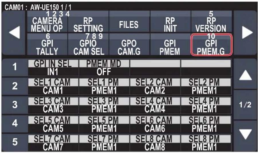

indicates factory default settings.
| Item Setting value Setting details | ||
| GPI IN SEL*1 | IN1 IN4 | For each of the PRESET_MEM_GROUP_IN1 to 4 inputs on the TALLY/GPIO 1 connector, it is possible to specify preset playback of a maximum of 10 cameras. |
| PMEM MD*1 | OFFSEPARATEALL | Set the operation mode for each of the PRESET_MEM_GROUP_IN1 to 4 on the TALLY/GPIO 1 connector.OFF: Preset playback is not performed even if there is input to PRESET_MEM_GROUP_IN1 to 4.SEPARATE: If there is input to PRESET_MEM_GROUP_IN1 to 4, preset playback instructions are performed according to the subsequent settings SEL1 to SEL10.ALL: Specify playback of the preset number set in SEL1 PM for all connected cameras when there is input through PRESET_MEM_GROUP_IN1. |
| SEL1 CAM*1 | CAM1 CAM200 | Select the camera number to playback. |
| SEL1 PM*1 | PMEM1 PMEM100 | Allocate the preset playback number to the camera selected with SEL1 CAM.However, when the [PMEM MD] is [ALL], the preset number for specifying playback of all connected cameras is set. |
| SEL2 CAM*1 | CAM1CAM2 CAM200 | Select the camera number to playback. |
| SEL2 PM*1 | PMEM1 PMEM100 | Allocate the preset playback number to the camera selected with SEL2 CAM. |
*1: This item is saved to the memory card by MAINTENANCE > RP SETTING > DATA SAVE.
| Item Setting value Setting details | ||
| SEL3 CAM*1 | CAM1 CAM3 CAM200 | Select the camera number to playback. |
| SEL3 PM*1 | PMEM1 PMEM100 | Allocate the preset playback number to the camera selected with SEL3 CAM. |
| SEL4 CAM*1 | CAM1 CAM4 CAM200 | Select the camera number to playback. |
| SEL4 PM*1 | PMEM1 PMEM100 | Allocate the preset playback number to the camera selected with SEL4 CAM. |
| SEL5 CAM*1 | CAM1 CAM5 CAM200 | Select the camera number to playback. |
| SEL5 PM*1 | PMEM1 ... PMEM100 | Allocate the preset playback number to the camera selected with SEL5 CAM. |
| SEL6 CAM*1 | CAM1 CAM6 CAM200 | Select the camera number to playback. |
| SEL6 PM*1 | PMEM1 PMEM100 | Allocate the preset playback number to the camera selected with SEL6 CAM. |
| SEL7 CAM*1 | CAM1 CAM7 CAM200 | Select the camera number to playback. |
| SEL7 PM*1 | PMEM1 PMEM100 | Allocate the preset playback number to the camera selected with SEL7 CAM. |
| SEL8 CAM*1 | CAM1 CAM8 CAM200 | Select the camera number to playback. |
| SEL8 PM*1 | PMEM1 PMEM100 | Allocate the preset playback number to the camera selected with SEL8 CAM. |
| SEL9 CAM*1 | CAM1 CAM9 CAM200 | Select the camera number to playback. |
| SEL9 PM*1 | PMEM1 PMEM100 | Allocate the preset playback number to the camera selected with SEL9 CAM. |
| SEL10 CAM*1 | CAM1 CAM10 CAM200 | Select the camera number to playback. |
| SEL10 PM*1 | PMEM1 PMEM100 | Allocate the preset playback number to the camera selected with SEL10 CAM. |
*1: This item is saved to the memory card by MAINTENANCE > RP SETTING > DATA SAVE.
SYSTEM
| ⇒ "CAMERA" (page 69) |
| ⇒ "CONNECT SETTING" (page 70) |
| ⇒ "MANUAL IP SET" (page 71) |
| ⇒ "AUTO IP SET" (page 72) |
| ⇒ "RP IP SET" (page 73) |
| ⇒ "TRACKING" (page 74) |
CAMERA
● The setting values will vary depending on the connected camera.

____ indicates factory default settings.
| Item Setting value Setting details | ||
| CAM POWER | NONGRP OFFGRP ONALL OFFALL ON | Execute power On/Off instructions in regard to connected remote cameras.NON:Power On/Off instructions not executed.GRP OFF:Execute power Off (standby) instructions in regard to remote cameras belonging to the currently selected camera group.GRP ON:Execute power On instructions in regard to remote cameras belonging to the currently selected camera group.ALL OFF:Execute power Off (standby) instructions in regard to remote cameras set in this unit.ALL ON:Execute power On instructions in regard to remote cameras set in this unit.● Depending on the number of remote cameras connected, the unit may take some time before it can be operated. |
| AUTO POWER*1 | OFFON | The power of remote cameras set in the unit turns on when the power of this unit is turned on.● Depending on the number of remote cameras connected, the unit may take some time before it can be operated. |
| CAM LOCK | UNLOCKLOCK | This feature is available when connected to AW-UE150 via LAN.When “LOCK” is selected, this unit and currently selected remote cameras cannot be controlled from another AW-RP150. While LOCK is on, currently selected remote cameras can only be controlled from the AW-RP150 on which LOCK was executed.Note that if you switch to another remote camera while LOCK is on, the LOCK is maintained on the remote cameras prior to camera selection, but the remote cameras after camera selection do not have LOCK applied.A key mark is displayed next to the camera name at the TOP of the LCD panel while LOCK is on. When “UNLOCK” is selected, the LOCK is released and the key mark disappears.Green key mark:This means that LOCK has been executed on this unit.Red key mark:This means that another AW-RP150 has been used for LOCK. Operation is not possible in this case. |
*1: This item is saved to the memory card by MAINTENANCE > RP SETTING > DATA SAVE.
■CONNECT SETTING
● The setting values will vary depending on the connected camera.


____ indicates factory default settings.
| Item Setting value Setting details | ||
| CAM SEL | 1 200 | Select the camera control number for which you want to configure settings.The network settings for the selected camera control number will appear in the screens that follow. |
| CNNCT MD | SerialLAN | Select the connection mode for the camera. |
| DATA SAVE | NO?YES? | Save the setting information for the unit.Do not turn off the power of the unit or remove the memory card until this process is complete. |
| DATA LOAD | NO?YES? | Load the file with the stored connections settings from the memory card.The screen switches to the one for selecting files when you select "YES?".Turn the F1 dial to select the file, then press the F1 dial to load it.Do not turn off the power of the unit or remove the memory card until this process is complete. |
| CAM1*1,*2 | NONSerialLAN | Displays the connection mode for camera 1 to camera 200. |
| CAM2*1,*2 CAM200 *1,*2 | NONSerialLAN | |
*1: This item is saved to the memory card by MAINTENANCE > RP SETTING > DATA SAVE. *2: This item is saved to the memory card by SYSTEM > CONNECT SETTING > DATA SAVE.
■MANUAL IP SET
● The setting values will vary depending on the connected camera.

indicates factory default settings.
| Item Setting value Setting details | ||
| CAM SEL*1, *2 | 1 200 | Select the camera control number for which you want to configure settings.The setting ranges are as follows.1 to 200The network settings for the selected camera control number will appear in the screens that follow. |
| CAM IP*1,*2 | Sets the IP address of the camera.The setting ranges are as follows.(IP addresses are assigned in order starting with 192.168.0.10 for CAM1 under factory default conditions.) | |
| PORT*1, *2 | 1 80 65535 | Sets the port number of the camera. |
| UPLOAD | NO?YES? | Turn the F4 dial to select “YES?” and press the F4 dial so the IP address and port number for the camera are set.● Settings are not updated until [UPLOAD] is executed after the settings are changed. |
*1: This item is saved to the memory card by MAINTENANCE > RP SETTING > DATA SAVE.
*2: This item is saved to the memory card by SYSTEM > CONNECT SETTING > DATA SAVE.
AUTO IP SET
● The setting values will vary depending on the connected camera.

indicates factory default settings.
| Item Setting value Setting details | ||
| AUTO SET | NONRENEWKEEP | NON:No search is made for remote cameras.RENEW:The unit first searches within the same subnet. After this, each detected remote camera is allocated a camera number in order.At this time, each remote camera IP address is overwritten with the connection destination IP address value set for each camera number in the unit.KEEP:The unit first searches within the same subnet.After this, newly detected remote cameras are linked with camera numbers whose connection type is set as “NON” on this unit.At this time, the IP addresses set for the remote cameras are saved as they are and the connection destination IP addresses set in this unit are overwritten. |
| NEW The number of newly detected cameras is displayed. | ||
| TOTAL | The number of devices currently being managed by the unit + Number of newly detected devices is displayed. | |
| EXEC | NONRETRYSETTING | NON:IP address setting operation is not performed.RETRY:Execute the “RENEW” or “KEEP” process again.SETTING:The results of “RENEW” or “KEEP” are reflected.With “RENEW”, the IP on the camera is also changed at this time.Refer to “Setting the IP addresses automatically (auto IP setting)” (page 33) for details. |
■RP IP SET
● The setting values will vary depending on the connected camera.
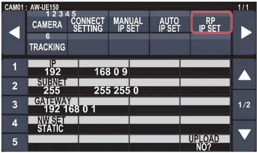

indicates factory default settings.
| Item Setting value Setting details | ||
| IP*1 | 192.168.0.9 Sets the IP address of the unit.This is disabled when the setting for [NW SET] is “DHCP”. | |
| SUBNET*1 | 255.255.255.0 | Sets the subnet mask of the unit. |
| GATEWAY*1 | 192.168.0.1 Sets the default gateway of the unit. | |
| NW SET*1 | STATIC DHCP | Select whether to make the IP address setting for the unit by obtaining from the DHCP server [DHCP] or setting with manual [STATIC]. |
| UPLOAD*1 | NO? YES? | Turn the F4 dial to select “YES?” and press the F4 dial so the IP address and port number for the camera are set.Settings are not updated until [UPLOAD] is executed after the settings are changed. |
| PORT C1*1 | 61000 | It is possible to allocate reception port numbers for each camera selection button. |
| PORT C2*1 | 61002 | |
| PORT C3*1 | 61004 | |
| PORT C4*1 | 61006 | |
| PORT C5*1 | 61008 | |
| PORT C6*1 | 61010 | |
| PORT C7*1 | 61012 | |
| PORT C8*1 | 61014 | |
| PORT C9*1 | 61016 | |
| PORT C10*1 | 61018 | |
| MAC ADDRESS | - | Display the unit's MAC address. (Display only) |
*1: This item is saved to the memory card by MAINTENANCE > RP SETTING > DATA SAVE.
■TRACKING
● The setting values will vary depending on the connected camera.

indicates factory default settings.
| Item Setting value Setting details | ||
| TR CONT*1 | NONLAN | Connection with automatic tracking software becomes possible by selecting “LAN”. |
| TR IP*1 | 192.168.0.210 Set the | IP address of the automatic tracking software. |
| PORT*1 | 1 1337 65535 | Set the PORT number of the automatic tracking software. |
| UPLOAD | NO?YES? | Maintain the connection settings of the automatic tracking software.● Settings are not updated until [UPLOAD] is executed after the settings are changed. |
*1: This item is saved to the memory card by MAINTENANCE > RP SETTING > DATA SAVE.
PMEM/TMEM
■ Operating preset memory (PMEM)
The preset memory of a remote camera can be operated from the unit.
The following settings that you have adjusted in advance can be stored in preset memory.
- Pan/tilt positions
- Zoom positions
- Focus positions
● Lens iris settings (manual iris only) ● White balance settings Gain
Notes
● The number of preset memory that can be registered differs depending on the remote camera. For details, check the Operating Instructions for the corresponding model. ● The starting positions for the preset memory and tracing memory share preset memory numbers 1 to 10 of the camera. Be aware that if preset memories have been first registered with [PMEM STORE], these will be overwritten if tracing memories are registered.
■ Operating tracing memory (TMEM)
The unit incorporates tracing memory (TMEM) for recording a series of operations that were performed for a connected remote camera.
This feature allows you to duplicate the recorded operations of a remote camera.
| Recording target Camera numbers CAM1 to CAM10 | |
| Functions that can be recorded | Pan, tilt, zoom, focus, iris, and white balance mode |
| Recording time Up to 5 minutes per camera | |
| Number of recording memory | Up to 10 per camera |
Notes
● The starting positions for the tracing memory are shared with the preset memory.
This means that the start positions numbers 1 to 10 for the tracing memory are saved in the preset memories numbers 1 to 10 of the camera.
Be aware that if preset memories have been first registered with [PMEM STORE], these will be overwritten if tracing memories are registered.
Also be aware that if you use [PMEM STORE] to register preset memories after registering tracing memories, the tracing memory start positions will be overwritten by the positions registered as preset memories with [PMEM STORE].
- The last point when tracing memory is recalled may not match that at the time of recording because of the error of movement of the remote camera.
Taking precautions such as the following can help reduce the error.
- Use the lens zoom at the WIDE side (wide-angle end).
- Perform pan, tilt, zoom, and focus operations slowly.
- Set a short recording time.
Execute tracing memory recalling several times to sufficiently check the operation of the remote camera before you begin operation.
- You can view the preset memory registration status for the selected remote camera and operate preset memories by selecting preset numbers.


| Item Setting value | Setting details | |
| 1i100(These are preset numbers.) | PRE1iPRE100(Displayed only in the mode for displaying 20 per page.) | The preset memory registration status for the selected remote camera is displayed.There are two display modes. A mode where 20 are displayed per page and a mode where 50 are displayed per page. In the mode that enables display of 20, the names of the preset memories are also displayed.Change the display mode with the [PMEM/TMEM] button > [SETTING] > [LIST ITEM].The gray display indicates that it is currently registered.Preset memory numbers in yellow indicate currently selected preset memories.The preset memory is executed when the number is touched.By touching the preset number with the F1 dial pressed down you can register the preset memory. |
■PMEM DIRECT
- You can directly instruct to execute by entering the preset number.

____ indicates factory default settings.
| Item Setting value Setting details | ||
| RCL SP MD*1 | CAMERARP | Determine the playback mode of the preset speed for playing back the preset memory.CAMERA:Playing back at the preset speed set in the remote camera.RP:Playing back at the preset speed registered when the preset memory was registered. |
| SPEED MD Display only | The mode of the speed | for playing back the preset memory is displayed.STEP:Playback moves to the preset position at the specified speed.TIME:Playback moves to the preset position in the specified time. |
| SPEED Display only The | movement speed or time | up to the preset position is displayed.When the [SPEED MD] is “STEP”, this displays the speed of movement to the preset position.When it is “TIME”, this displays the time it will take to move to the preset position. |
| PMEM 1 | ⋮100 | The currently selected preset number is displayed. |
| 0⋮9 | – When the | preset memory number is touched and “EXEC” is selected, the preset is played back.The touched number is displayed in the [PMEM] item.When “CLEAR” is selected while a preset number is being touched, the input number is cleared. |
| CLEAR | – | |
| EXEC | – | |
*1: This item is saved to the memory card by MAINTENANCE > RP SETTING > DATA SAVE.
■PMEM STORE
- You can register the preset memory by entering the preset number.
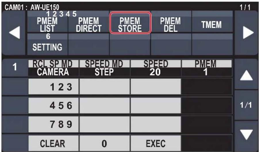
____ indicates factory default settings.
| Item Setting value Setting details | ||
| RCL SP MD | CAMERARP | Determine the playback mode of the preset speed for playing back the preset memory.CAMERA:During preset memory playback, playback is at the preset speed set in the remote camera.RP:Playing back at the preset speed registered when the preset memory was registered. |
| SPEED MD | STEPTIME | The mode of the speed for playing back the preset memory is displayed.STEP:Playback moves to the preset position at the specified speed.TIME:Playback moves to the preset position in the specified time. |
| SPEED – The movement | speed or time up to the | preset position is displayed.When the [SPEED MD] is [STEP], this displays the speed of movement to the preset position.When it is [TIME], this displays the time it will take to move to the preset position. |
| PMEM 1 | ⋮100 | The currently selected preset memory number is displayed. |
| 0⋮9 | – When the | preset memory number is touched and “EXEC” is selected, the preset is registered.The touched number is displayed in the [PMEM] item.When [CLEAR] is selected while a preset number is being touched, the input number is cleared. |
| CLEAR – | ||
| EXEC – | ||
■PMEM DEL
- You can delete the preset memory.

____ indicates factory default settings.
| Item Setting value Setting details | ||
| MODE | ALLDIRECTRANGE | Select the delete mode for the preset memory.ALL:Delete entire preset memory.DIRECT:Use the [0] to [9] buttons to specify a preset memory number to delete.RANGE:Delete the preset memory in the range delimited by [START] and [END]. |
| START | - | When [RANGE] is selected in [MODE], specify the deletion range for the preset memory with [START](F2 dial) to [END] (F3 dial), and execute with “EXEC”. |
| END - | ||
| PMEM | - | When [MODE] is [DIRECT], enter the preset memory to be deleted (displayed in PMEM), thenexecute with “EXEC”.The numbers temporarily entered are disabled with “CLEAR”. |
| 0!9 | - | |
| CLEAR - | ||
| EXEC | - | |
TMEM
● The setting values will vary depending on the connected camera.

____ indicates factory default settings.
| Item Setting value Setting details | ||
| MODE | STORERECALLDELRESTORE | Select the operation to perform on tracing memory.STORE:Register tracing memory.RECALL:Play back tracing memory.DEL:Delete tracing memory.RESTORE:Edit the registered tracing memory. |
| START NO? | YES?(Only when [MODE] is [STORE]) | When [STORE] is selected in [MODE], select [YES?] and press the F2 dial to start registration of the tracing memory. |
| TMEM 1 | ⋮100 | The currently selected tracing memory number is displayed. |
| Remaind 5m00s The length of time it is possible to save for the tracing memory is displayed. | ||
| 1⋮10 | - | Select to register, playback, delete, and edit tracing memory.The selected number operates according to the [MODE].Numbers in yellow are numbers for which tracing memory has been registered. |
| TIME | 0m00s | The time required for registration of the currently selected tracing memory is displayed.The setting is 0m00s when not registered. |
| DATA SAVE | NO?YES? | The tracing memory data is stored to the memory card.The data for all of the tracing memories stored in the unit will be saved as a single file to the memory card.Do not turn off the power of the unit or remove the memory card until this process is complete. |
| DATA LOAD | NO?YES? | The tracing memory data is loaded from the memory card.The screen switches to the one for selecting files when you select “YES?”.Turn the F1 dial to select the file, then press the F1 dial to load it.Do not turn off the power of the unit or remove the memory card until this process is complete. |
Memo
- When performing tracing memory operations, do not operate from more than one AW-RP150. If tracing memory operations are performed on the same remote camera from more than one AW-RP150, operation will not be correct.
■SETTING
● Make basic settings for preset memory and tracing memory.

____ indicates factory default settings.
| Item Setting value Setting details | ||
| SCOPE A | B | Specify the playback targets for items registered in the tracing memory.A:Pan, Tilt, Zoom (including digital zoom), Focus, Iris, Gain, white balance adjustment valueB:Pan, Tilt, Zoom (including digital zoom), Focus, IrisC:Pan, Tilt, Zoom (including digital zoom), Focus |
| RCL SP MD*1 | CAMERARP | Determine the playback mode of the preset speed for playing back the preset memory.CAMERA:Playing back at the preset speed set in the remote camera.RP:Playing back at the preset speed registered when the preset memory was registered. |
| HOME Return the pan-tilt | head to home position. | |
| SPD UNIT STEP | TIME | The mode of the speed for playing back the preset memory is displayed.STEP:Playback moves to the preset position at the specified speed.TIME:Playback moves to the preset position in the specified time. |
| SPEED TBL SLOW | FAST | Set the mode of the speed when playing back preset memory. |
| SPEED | (Setting on the remote camera) | The movement speed or time up to the preset position is displayed.When the [SPD UNIT] is [STEP], this displays the speed of movement to the preset position.When it is [TIME], this displays the time it will take to move to the preset position. |
| D-EXT | OFFON | Set whether to set the digital extender On/Off when registering preset memories. |
| ZOOM MD | A | Select the zoom operation for when preset memory is recalled.A:Perform the zoom operation in line with the pan/tilt operation.B:Perform the zoom operation quicker than the pan/tilt operation. |
| B | ||
| CROP | OFFON | When the preset memory is played back, set whether the reproduction of content set in the various [CROP] menus is off/on. |
| LIST ITEM*1 | 2050 | Set the number of preset numbers displayed on 1 page in the PMEM LIST screen.20:The number and preset name are displayed.50:Only the number is displayed. |
| PM NM SV | NO?YES? | Save the name data for the preset memory displayed in the [PMEM LIST] menu.The screen switches to the one for selecting files when you select “YES?”.Turn the F1 dial to select the file, then press the F1 dial to store it.Do not turn off the power of the unit or remove the memory card until this process is complete. |
| PM NM LD | NO?YES? | Load the name data for the preset memory displayed in the [PMEM LIST] menu.The screen switches to the one for selecting files when you select “YES?”.Turn the F1 dial to select the file, then press the F1 dial to load it.Do not turn off the power of the unit or remove the memory card until this process is complete. |
*1: This item is saved to the memory card by MAINTENANCE > RP SETTING > DATA SAVE.
| Item Setting value Setting details | ||
| PM G.CAL +1 | GROUP1⋮GROUP4 | Execute the setting content for [GPI IN SEL] set with the [MAINTENANCE] button > [GPI PMEM.G] menu.Select the target group and press the F1 dial to execute.GROUP1:IN1 for GPI IN SELGROUP2:IN2 for GPI IN SELGROUP3:IN3 for GPI IN SELGROUP4:IN4 for GPI IN SEL |
*1: This item is saved to the memory card by MAINTENANCE > RP SETTING > DATA SAVE.
Setup Software is an application for configuring the settings for connecting the unit with the remote cameras from a personal computer. The settings can be configured while confirming each item in a list.
- The settings for connecting the unit with the remote cameras can also be configured using just the unit. For how to configure the settings on the unit, refer to "Settings for connecting with the remote cameras" (page 32).
Notes
When using Setup Software to configure the settings from a personal computer, observe the following.
- Do not perform any operation on the unit.
- Do not start Setup Software on any other computer in the same network.
- Do not use "Easy IP Setup Software".
Installing the software
This section describes how to install Setup Software.
You can obtain the software from the Service and Support page of the following website.
https://pro-av.panasonic.net/
- Download the Setup Software zip file from the Service and Support page of the website.
- Double-click the downloaded zip file to decompress the file.
- Double-click "RP150PCTool *.exe" in the "Setup Software" folder to start the Setup Software.
- The website has Setup Software for Windows® and Windows® 10. The location marked by the asterisk (*) will be "7" for the Windows® 7 version and "10" for the Windows® 10 version.
Configuring the settings of the personal computer
Configure the following settings of the personal computer before connecting it to the unit.
IP address: Set an IP address that is not a duplicate of the IP address set on the unit or any IP address set on the devices (remote cameras, etc.) connected within the same subnet.
Subnet mask: Set the same subnet mask as that set on the unit.
Default gateway: Set the same default gateway as that set on the unit.
You can view the IP address, subnet mask, and default gateway set in the unit with the [SYSTEM] button > [RP IP SET].
IP address: "IP" item
Subnet mask: "SUBNET" item
Default gateway: "GATEWAY" item
The screens of Windows 7 are used in the explanations in this manual.
If you are using an operating system other than Windows 7, some of the items displayed on the screens may differ.
Settings for connecting with the remote cameras
Displaying the [Setting] tab
The settings are based on the data saved with [DATA SAVE] with the [SYSTEM] button > [CONNECT SETTING] menu on the unit. The data is stored under PRIVATE\MEIGROUP\PAVCN\SBG\SYSCAM\RP150\DATA\Network.s15.
[LOAD] loads the data that was saved with [DATA SAVE] in the [CONNECT SETTING] menu on the unit. The loaded data is reflected on the screen.
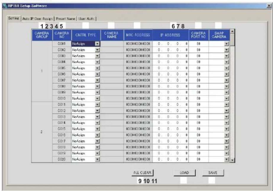
1 CAMERA GROUP
The camera group number is displayed.
2 CAMERA NO
The camera number is displayed.
3 CNTRL TYPE
Select the connection type.
Click ▶ on the right and select the connection type from amongst "Serial", "Network", and "NoAsign".
Serial : Serial connection
Network : IP connection
NoAsign : No setting (factory default)
"Serial" can only be selected with GROUP1.
4 CAMERA NAME
Displays the camera name set on the remote camera.
● These are displayed when they are acquired with [AUTO IP SET] on the main unit or with [AUTO IP CAM ASSIGN] on this software.
5 MAC ADDRESS
Displays the MAC addresses of remote cameras with links set with camera numbers of this unit.
● These are displayed when they are acquired with [AUTO IP SET] on the main unit or with [AUTO IP CAM ASSIGN] on this software.
6 IP ADDRESS
Set the IP address of the remote camera that will be the connection destination.
7 CAMERA PORT NO
Set the port number of the remote camera that will be the connection destination.
After input, click the [SAVE] button to reflect the changed content. Settable range: 1 to 65535
However, even within this range, the following values cannot be set.
20, 21, 23, 25, 42, 53, 67, 68, 69, 110, 123, 161, 162, 995, 10669, 10670
8 SWAP CAMERA
You can switch the remote camera set as the connection destination between 2 camera numbers.
Camera numbers "C001" to "C200" are displayed when ▼ is clicked.
9 ALL CLEAR button
Clear all setting data.
10 LOAD button
The file loading screen is displayed and the specified file is loaded. Data saved in the main unit is stored in the following path. Under \PRIVATE\MEIGROUP\PAVCN\SBG\SYSCAM\RP150\DATA File name: Network.s15
- Use data that was saved by this unit.
11 SAVE button
The set data is saved.
Save the data file saved here under \PRIVATE\MEIGROUP\PAVCN\SBG\SYSCAM\RP150\DATA.
When loaded with "DATA LOAD" in the [SYSTEM] button > [CONNECT SETTING] menu of this unit, the results are updated in the main unit.
Note
- Be aware that if you load data saved in the [User Auth.] tab and then save in the [Setting] tab, the content set in the [User Auth.] tab is not updated on the unit.
Displaying the [Auto IP Cam Assign] tab
When a "NETWORK SEARCH" is executed and applicable remote cameras are found, they are displayed in a list. The list shows them in the order they were found.

1 CAMERA NAME
The camera names found in the search are displayed.
2 MAC ADDRESS
The MAC addresses found in the search are displayed.
3 IP ADDRESS
The IP addresses found in the search are displayed.
4 CAMERA PORT NO
The port numbers found in the search are displayed.
5 ASSIGN CAM NO
Allocate the camera numbers to be assigned to the remote cameras returned in the search results.
● Camera number allocations made here are reflected in the main unit.
6 NETWORK SEARCH button
A search is made for remote cameras on the network.
A list of the search results is displayed.
7 SAVE button
Save the set content.
When storing on a memory card, save under the following path.
The data is saved under \PRIVATE\MEIGROUP\PAVCN\SBG\SYSCAM\RP150\DATA.
When loaded with "DATA LOAD" in the [SYSTEM] button > [CONNECT SETTING] menu of this unit, the results are updated in the main unit.
Displaying the [Preset Name] tab
You can set a name of up to 8 characters for a preset number.
You can edit the data saved with the [PMEM/TMEM] button > [SETTING] > [PM NM SV].
By saving the data after editing and "LOAD" to the main unit, it can be displayed in the PMEM LIST screen.
Note that if a preset name is notified from the remote camera, the name notified from the remote camera is prioritized over this name.

1 CAMERA NO
Select the camera number for which settings are to be edited.
When [LOAD] is used to load a file, the camera number at the time of saving is displayed.
2 Setting area for PRESET names
Set a name for each PRESET number.
When [LOAD] is used to load a file, the name at the time of saving is displayed.
Names can be a maximum of 8 characters.
The following characters can be displayed.
| Half-size numeric characters 0123456789 | |
| Half-size alphabetical characters (upper and lower cases) | ABCDEFGHIJKLMNOPQRSTUVWXYZ abcdefghijklmnopqrstuvwxyz |
| Symbols - ._, + / () [ ] (and spaces) | |
3 ALL CLEAR button
Delete the set names.
4 LOAD button
Load the saved data.
Data saved in the main unit is stored in the following path.
The data is stored under \PRIVATE\MEIGROUP\PAVCN\SBG\SYSCAM\RP150\DATA.
File name: Cam***Pr.p15 (*** is the camera number)
5 SAVE button
Save the set data.
Save the data for the camera number that is currently set.
When storing on a memory card, save under the following path.
The data is stored under \PRIVATE\MEIGROUP\PAVCN\SBG\SYSCAM\RP150\DATA.
File name: Cam***Pr.p15 (*** is the camera number)
Displaying the [User Auth.] tab
Perform user authentication settings for the connection destination remote camera.
Cameras can be set individually or all at once.
These settings are set based on the data saved with "DATA SAVE" with the [SYSTEM] button > [CONNECT SETTING] menu on the unit.

1 CAMERA NO
Select the camera number for which user authentication is to be set.
Settings are made all at once if "ALL" is selected.
When a camera number is selected, the settings can be made for each camera number individually.
2 New User Name
Set the new user name.
For this setting, set the user name set in the remote camera to be connected to.
3 New Password/Retype New Password
Set the new password.
For this setting, set the password set in the remote camera to be connected to.
4 LOAD button
The file loading screen is displayed and the specified file is loaded.
Data saved in the main unit is stored in the following path.
The data is stored under \PRIVATE\MEIGROUP\PAVCN\SBG\SYSCAM\RP150\DATA.
File name: Network.s15
- Use data that was saved by this unit.
5 SAVE button
Save the set data.
Save the data for the camera number that is currently set.
When storing on a memory card, save under the following path.
The data is stored under \PRIVATE\MEIGROUP\PAVCN\SBG\SYSCAM\RP150\DATA.
When loaded with "DATA LOAD" in the [SYSTEM] button > [CONNECT SETTING] menu of this unit, the results are updated in the main unit.
Note
- Be aware that if you load data in the [Setting] tab and then save in the [User Auth.] tab, the content set in the [Setting] tab is not updated on the unit.
IP connection settings
| Indication Description | |
| Unavailable network setting | The entered IP address, subnet mask, or port number cannot be set.Enter a correct value.For details, refer to “Network settings of the unit” (page 30). |
| IP Duplicate! | The entered IP address is a duplicate of the IP address set for another item (the connection destination IP address for another camera number or the IP address of the unit). |
| Please reboot RP | The unit needs to be rebooted.Turn the unit’s power off and then back on. |
Preset memory
| Indication Description | |
| Used by TMEM. | Overwriting or deletion is not possible because tracing memory is registered to the selected number button. |
Tracing memory
| Indication Description | |
| TM##:Waiting Opr. | The recording operation wait state of tracing memory. |
| TM##: #m##sStoring... | Recording tracing memory. |
| TM##: #m##s/#m##sStandby Recall | The recall wait state of tracing memory. |
| TM##: #m##s/#m##sRecalling... | Recalling tracing memory. |
| TM##: #m##s/#m##sStandby Restore | The restore standby state of tracing memory. |
| TM##: #m##s/#m##sRestoring... | Restoring tracing memory. |
| CAM GRP can't be changed in TMEM | The camera group cannot be switched in TMEM mode. |
- A number is displayed instead of “#”.
Memory card
| Indication Description | |
| INITIALIZING...NOT REMOVE CARD | Initializing the memory card.Do not remove the memory card. |
| SAVING...NOT REMOVE CARD | Saving data to the memory card.Do not remove the memory card. |
| LOADING...NOT REMOVE CARD | Reading data from the memory card.Do not remove the memory card. |
| LOAD ERROR! | A file cannot be read by the unit or selected remote camera. The following files are incompatible.A file saved with a different model than the currently selected remote camera.A file containing corrupted data⇒ Check that a file is stored.⇒ Check that the memory card has been correctly inserted. |
| SAVE ERROR! | Failed to write to the memory card.⇒ Check that the memory card has been correctly inserted.⇒ Check that the memory card is supported by the unit.⇒ Check that the memory card has been formatted.⇒ Check that the memory card has available space.⇒ Check if the write protect switch on the card is set to “LOCK”. |
| FORMAT ERROR! | Failed to format the memory card.⇒ Check that the memory card has been correctly inserted.⇒ Check that the memory card is supported by the unit.⇒ Check if the write protect switch on the card is set to “LOCK”. |
| COMPLETEPush OK to reboot system. | The unit needs to be rebooted.Turn the unit’s power off and then back on. |
| UPGRADE ERROR! | Updating of the unit failed.⇒ Check that the memory card has been correctly inserted.⇒ Check that the memory card is supported by the unit.⇒ Check that a file is stored.⇒ Check if the write protect switch on the card is set to “LOCK”. |
Setup software
| Indication Description | |
| Unavailable network setting. | The entered IP address and port number cannot be set.Set correct values.For details, refer to “Network settings of the unit” (page 30) to “Settings for connecting with the remote cameras” (page 38). |
| Entered information is incorrect. Enter again. | The entered information includes characters that cannot be used on the unit. |
| Complete the “New User Name” field. | Enter the user name in the “New User Name” box. |
| Complete the “New Password” field. | Enter the password in the “New Password” box. |
| Complete the “Retype New Password” field. | Enter the password in the “Retype New Password” box. |
| Password entered in the “Retype New Password” field is incorrect. | The password entered in the “Retype New Password” box does not match the one entered in the “New Password” box. |
| Symptom Cause and Measure Reference Page | ||
| Cannot turn the power of the unit on. | Is external DC power being supplied? - | |
| Is the DC plug of the external DC power supply connected to the unit properly? | - | |
| Cannot operate a remote camera. | Is a power supply connected to the remote camera properly? - | |
| Are the remote camera and unit connected properly? P. 16 to P. 19 | ||
| Are the connection settings correct? P. 32 to P. 38 | ||
| Is the remote camera in the standby state?→ Turn on the power of the remote camera. | P. 21 | |
| Is the remote camera selected properly? P. 23 to P. 24 | ||
| Is the ENABLE button indicator on? P. 20 | ||
| Has user authentication been set for the remote camera? P. 87 | ||
| The remote camera moves in the opposite direction to the operation of the PAN/TILT lever. | Is the installation method setting configured for the remote camera?→ The setting needs to be configured in accordance with the actual installation state (mounted right side up or upside down).Refer to the Operating Instructions for the remote camera. | - |
| Is the movement direction set properly on the unit? | P. 54 | |
| The remote camera moves in the opposite direction to operation of the ZOOM button and FOCUS dial. | Is the movement direction set properly on the unit? | P. 54 |
Unit: mm (inch)


● Mount angle attachment position
Power supply: 12 V DC (==) (10.8 V to 13.2 V)
42 V - 57 V DC (===) (PoE+ power supply)
Current consumption: 1 A (Power supply: 12 V DC)
0.6 A (PoE+ power supply)
The symbols on this product (including the accessories) represent the following:
--- DC

indicates safety information.
General
Ambient operating
temperature: 0 °C to 40 °C (32 °F to 104 °F)
Allowable humidity: 10% to 90% (no condensation)
Weight: Approx. 3.2 kg (7.05 lb)
Dimensions (W × H × D): 342 mm × 178 mm × 245 mm
(13-15/32 inches × 7 inches ×
9-21/32 inches)
(excluding protrusions)
■Input/output connectors
DC 12 V IN (XLR 4-pin)
3G SDI IN / 3G SDI ACTIVE THRU OUT:
SMPTE292/75 Ω
Supported formats:
1080/59.94p*, 1080/59.94i, 1080/23.98p,
1080/23.98PsF, 1080/50p*, 1080/50i, 1080/25p,
1080/25PsF
*: Only Level A is supported
IP CONT (RJ-45): 10BASE-T/100BASE-TX
PoE+ input
Connection cable: LAN cable, max. 100 m (328 ft)
- When connecting the unit via a switching hub Straight cable or a cross cable (category 5e cable), STP (Shielded Twisted Pair) cable recommended
- When connecting the unit directly: Crossover cable (category 5e cable), STP (Shielded Twisted Pair) cable recommended
SERIAL CONT (RJ-45):
RS-422 (control signals for remote cameras)
Connecting cable:
Straight cable (category 5e or better shielded
cable), max. 1000 m (3280 ft)
TALLY OUT: Open collector output (negative logic)
Maximum voltage resistance DC 24 V, Maximum
current 50 mA
TALLY/GPIO 1 (D-sub 25-pin, female, inch thread):
TALLY IN : 10 inputs (for receiving photocoupler signals)
GPI : 6 inputs (for receiving photocoupler signals)
GPIO : 5 inputs (for receiving photocoupler signals) or
5 outputs (open collector outputs, negative logic)
● Input/output switched with menu settings
GPIO 2 (D-sub 25-pin, female, inch thread):
GPI : 10 inputs (for receiving photocoupler signals)
GPIO: 10 inputs (for receiving photocoupler signals) or
10 outputs (open collector outputs, negative logic)
● Input/output switched with menu settings
Reserve connectors:
2 connectors (for future expansion feature)
1. TALLY/GPIO 1 (JST: JBY-25S-1A3F(LF)(SN))
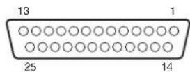
| Pin number | Signal name Description | tion of signal Operation | ||
| 1 | R_TALLY_IN_1 | TALLY IN1 to TALLY IN10 tally inputs | Contact input(Status operation) | |
| 14 | R_TALLY_IN_2 | |||
| 2 | R_TALLY_IN_3 | |||
| 15 | R_TALLY_IN_4 | |||
| 3 | R_TALLY_IN_5 | |||
| 16 | R_TALLY_IN_6 | |||
| 4 | R_TALLY_IN_7 | |||
| 17 | R_TALLY_IN_8 | |||
| 5 | R_TALLY_IN_9 | |||
| 18 | R_TALLY_IN_10 | |||
| 6 | GND | GND | ||
| 19 | DSUB1_GPI_1 | It is possible to allocate "GPI" settings in the[MAINTENANCE] > [RP SETTING] > [GPIO MD] menu settings.For details, refer to GPIO MODE: MODE1, GPIO MODE: MODE2 on the page 94. | Contact input (Trigger operation)Trigger width ≥ 30 ms | |
| 7 | DSUB1_GPI_2 | |||
| 20 | DSUB1_GPI_3 | |||
| 8 | DSUB1_GPI_4 | |||
| 21 | DSUB1_GPI_5 | |||
| 9 | DSUB1_GPI_6 | |||
| 22 | GND | GND | ||
| 10 | DSUB1_GPIO_1 | It is possible to allocate "GPIO" settings in the[MAINTENANCE] > [RP SETTING] > [GPIO MD] menu settings.For details, refer to GPIO MODE: MODE1, GPIO MODE: MODE2 on the page 94. | Input:Contact input (Trigger operation)Trigger width ≥ 30 msOutput:Open collector output(Status operation) | |
| 23 | DSUB1_GPIO_2 | |||
| 11 | DSUB1_GPIO_3 | |||
| 24 | DSUB1_GPIO_4 | |||
| 12 | DSUB1_GPIO_5 | |||
| 25 | GND | GND | ||
| 13 | ALARM | Alarm | Open collector output(Status operation) | |
Example of GPI OUT connection
Ensure that the conditions given below are satisfied.
Withstand voltage: Max. 24 V DC Current: Max. 50 mA

Example of TALLY IN and GPI IN connections Provide contact inputs.

You can allocate the "GPIO" settings as follows in [MAINTENANCE] > [RP SETTING] > [GPIO MD] in the menus.
■ GPIO MODE: MODE1
DSUB1
| Pin number | Signal name | |
| 1 R | TALLY_IN_1 | *1 |
| 14 R_TALLY_IN_2 | *1 | |
| 2R | TALLY_IN_3 | *1 |
| 15 R_TALLY_IN_4 | *1 | |
| 3 R | TALLY_IN_5 | *1 |
| 16 R_TALLY_IN_6 | *1 | |
| 4 R | TALLY_IN_7 | *1 |
| 17 R_TALLY_IN_8 | *1 | |
| 5 R | TALLY_IN_9 | *1 |
| 18 R_TALLY_IN_10 | *1 | |
| 6 GND | ||
| 19 G_TALLY_IN_1 | *1 | |
| 7 G | TALLY_IN_2 | *1 |
| 20 G_TALLY_IN_3 | *1 | |
| 8 G | TALLY_IN_4 | *1 |
| 21 G_TALLY_IN_5 | *1 | |
| 9G | TALLY_IN_6 | *1 |
| 22 | ||
| 10 G | TALLY_IN_7 | *1 |
| 23 G_TALLY_IN_8 | *1 | |
| 11 G | TALLY_IN_9 | *1 |
| 24 G_TALLY_IN_10 | *1 | |
| 12 Backup input | ||
| 25 GND | ||
| 13 ALARM | ||
■ GPIO MODE: MODE2
DSUB1
| Pin number $ignal name | ||
| 1 R | TALLY | IN_1 |
| 14 R | TALLY_IN_2 | |
| 2R | TALLY | IN_3 |
| 15 R | TALLY_IN_4 | |
| 3 R | TALLY | IN_5 |
| 16 R | TALLY_IN_6 | |
| 4 R | TALLY | IN_7 |
| 17 R | TALLY_IN_8 | |
| 5 R | TALLY | IN_9 |
| 18 R | TALLY_IN_10 | |
| 6 GND | ||
| 19 PRESET_MEM_GROUP_IN_1 | ||
| 7 | PRESET_MEM_GROUP_IN_2 | |
| 20 PRESET_MEM_GROUP_IN_3 | ||
| 8 | PRESET_MEM_GROUP_IN_4 | |
| 21 | MENU ENABLE_BOTTOM | |
| 9 | ||
| 22GND | ||
| 10 | GROUP_SELECT_OUT_1 | |
| 23 | GROUP_SELECT_OUT_2 | |
| 11 | GROUP_SELECT_OUT_3 | |
| 24 | GROUP_SELECT_OUT_4 | |
| 12 | GROUP_SELECT_OUT_5 | |
| 25 GND | ||
| 13 ALARM | ||
*1: Setting in the [MAINTENANCE] > [GPI TALLY] menu *2: Setting in the [MAINTENANCE] > [GPO CAM.G] menu *3: Setting in the [MAINTENANCE] > [GPI PMEM] menu
- GPIO 2 (JST: JBY-25S-1A3F(LF)(SN))
| Pin number $Signal name Description of signal Operation | |||
| 1 DSUB2_GPI_1 | It is possible to allocate "GPI" settings in the [MAINTENANCE] > [RP SETTING] > [GPIO MD] menu settings.For details, refer to GPIO MODE: MODE1, GPIO MODE: MODE2 below. | Contact input(Status operation) | |
| 14 DSUB2_GPI_2 | |||
| 2DSUB2_GPI_3 | |||
| 15 DSUB2_GPI_4 | |||
| 3 DSUB2_GPI_5 | |||
| 16 DSUB2_GPI_6 | |||
| 4 DSUB2_GPI_7 | |||
| 17 DSUB2_GPI_8 | |||
| 5 DSUB2_GPI_9 | |||
| 18 DSUB2_GPI_10 | |||
| 6 GND GND | |||
| 19 DSUB2_GPIO_1 | It is possible to allocate "GPIO" settings in the [MAINTENANCE] > [RP SETTING] > [GPIO MD] menu settings.For details, refer to GPIO MODE: MODE1, GPIO MODE: MODE2 below. | Input:Contact input (Trigger operation)Trigger width ≥ 30 msOutput:Open collector output(Status operation) | |
| 7 DSUB2_GPIO_2 | |||
| 20 DSUB2_GPIO_3 | |||
| 8 DSUB2_GPIO_4 | |||
| 21 DSUB2_GPIO_5 | |||
| 9DSUB2_GPIO_6 | |||
| 22DSUB2_GPIO_7 | |||
| 10 DSUB2_GPIO_8 | |||
| 23 DSUB2_GPIO_9 | |||
| 11 | DSUB2_GPIO_10 | ||
| 24 | GND GND | ||
| 12 | (For a future expansion feature) | ||
| 25 | GND GND | ||
| 13 | (For a future expansion feature) | ||
You can allocate the "GPIO" settings as follows in [MAINTENANCE] > [RP SETTING] > [GPIO MD] in the menus.
■ GPIO MODE: MODE1 DSUB2
| Pin number $ignal name | ||
| 1 | CAMERA_SELECT_IN_1 | |
| 14 | CAMERA_SELECT_IN_2 | |
| 2 | CAMERA_SELECT_IN_3 | |
| 15 | CAMERA_SELECT_IN_4 | |
| 3 | CAMERA_SELECT_IN_5 | |
| 16 | CAMERA_SELECT_IN_6 | |
| 4 | CAMERA_SELECT_IN_7 | |
| 17 | CAMERA_SELECT_IN_8 | |
| 5 | CAMERA_SELECT_IN_9 | |
| 18 | CAMERA_SELECT_IN_10 | |
| 6 GND | ||
| 19 | CAMERA_SELECT_OUT_1 | |
| 7 | CAMERA_SELECT_OUT_2 | |
| 20 | CAMERA_SELECT_OUT_3 | |
| 8 | CAMERA_SELECT_OUT_4 | |
| 21 | CAMERA_SELECT_OUT_5 | |
| 9 | CAMERA_SELECT_OUT_6 | |
| 22 | CAMERA_SELECT_OUT_7 | |
| 10 | CAMERA_SELECT_OUT_8 | |
| 23 | CAMERA_SELECT_OUT_9 | |
| 11 | CAMERA_SELECT_OUT_10 | |
| 24 | GND | |
| 12 | (For a future expansion feature) | |
| 25 | GND | |
| 13 | (For a future expansion feature) | |
■ GPIO MODE: MODE2 DSUB2
| Pin number | Signal name | |
| 1 | PRESET_SELECT_IN_1 | |
| 14 | PRESET_SELECT_IN_2 | |
| 2 | PRESET_SELECT_IN_3 | |
| 15 | PRESET_SELECT_IN_4 | |
| 3 | PRESET_SELECT_IN_5 | |
| 16 | PRESET_SELECT_IN_6 | |
| 4 | PRESET_SELECT_IN_7 | |
| 17 | PRESET_SELECT_IN_8 | |
| 5 | PRESET_SELECT_IN_9 | |
| 18 | PRESET_SELECT_IN_10 | |
| 6 GND | ||
| 19 | CAMERA_SELECT_IN_1 | |
| 7 | CAMERA_SELECT_IN_2 | |
| 20 | CAMERA_SELECT_IN_3 | |
| 8 | CAMERA_SELECT_IN_4 | |
| 21 | CAMERA_SELECT_IN_5 | |
| 9 | CAMERA_SELECT_IN_6 | |
| 22 | CAMERA_SELECT_IN_7 | |
| 10 | CAMERA_SELECT_IN_8 | |
| 23 | CAMERA_SELECT_IN_9 | |
| 11 | CAMERA_SELECT_IN_10 | |
| 24 | GND | |
| 12 | (For a future expansion feature) | |
| 25 | GND | |
| 13 | (For a future expansion feature) | |
*1: Setting in the [MAINTENANCE] > [GPIO CAM SEL] menu
*2: Setting in the [MAINTENANCE] > [GPI PMEM] menu
3. 3G SDI ACTIVE THRU OUT
BNC 75 Ω
The HD/SDI signals input through SDI IN are output as they are.
● Signals are not output unless the power of this unit is on.
4. 3G SDI IN
BNC 75 Ω
When the [PICTURE] button is lit, the input video is displayed on the LCD panel.
5. SERIAL CONT 1 to 5 (RJ-45)
Connect remote cameras with support for a serial connection to these connectors using LAN cables.
Connect them with straight cables (category 5e or better shielded cable).
| Pin number | Signal name D | Description of signal |
| 1 GND | Frame ground | |
| 2TALLY | Tally output (open collector) | |
| 3 TXD | Send data (-) | |
| 4 RXD | Receive data (-) | |
| 5 RXD+ | Receive data (+) | |
| 6 TXD+ | Send data (+) | |
| 7 | NC | Not used |
| 8 | NC | Not used |
● TALLY (pin number: 2) specifications
Voltage withstand: Max. 24 V DC
Current: Max. 50 mA
6. IP CONT (RJ-45)
Complies with 10BASE-T/100BASE-TX.
Allowing connection to a network device that supports the PoE+
standard (IEEE802.3at compliant).
7. 12V == IN (DC 12 V)
Hirose Electric: HA16RA-4P (77)
Accepts DC 12V inputs from an external power supply.
Input voltage range: 10.8 V to 13.2 V
 | Pin No. | Function |
| 1 | GND | |
| 2 | NC | |
| 3 | NC | |
| 4 | +12V |
Numeric
3G SDI 14
3G SDI ACTIVE THRU OUT 19, 92, 96
3G SDI IN 92, 96
3G SDI OUT 19
A
Auto IP setting 33
AV-HLC100 16
AW-UE150 7,16,17,18,19
C
Camera selection section 10
Color adjustment section 12
Connection destination IP addresses 32
D
Default gateway 31
F
Focus, zoom and iris section 11
FUNCTION 51
CAMERA INFO 52
CROP 56
HOUSING INFO 55
PTZ INFO1 53
PTZ INFO2 54
USER ASSIGN 51
G
GPIO 2 14, 92, 95
|
IP address 30
IP CONT 14,92,96
L
LAN cable 16, 17, 18, 19
Link settings 32
Live Production Center 16
M
MAC address 31
MAINTENANCE 57
CAMERA MENU OP 57
FILES 60
GPIO CAM SEL 63
GPI PMEM 66
GPI PMEM.G 67
GPI TALLY 62
GPO CAM.G 65
RP INIT 61
RP SETTING 58
RP VERSION 61
Memory card section 13
Menu operation section 9
MONI OUT 19
P
PAINT 40
BLACK GAMMA 44
BRIGHTNESS 50
CHROMA 42
COLOR CORRE 48
DC DTL 47
DNR 49
DRS 45
DTL 46
GAIN 42
GAMMA 44
KNEE 45
MATRIX 47
PED 41
SCENE 40
SHUTTER 41
WHITE BALANCE 43
WHITE CLIP 46
Pan and tilt section 10
PMEM/TMEM 75
PMEM DEL 79
PMEM DIRECT 77
PMEM LIST 76
PMEM STORE 78
SETTING 81
TMEM 80
R
Reception port number 31
Remote camera 7
s
SDI IN 19
SERIAL CONT 14,92,96
Setup Software 83
Subnet mask 30
SYSTEM 69
AUTO IP SET 72
CAMERA 69
CONNECT SETTING 70
MANUAL IP SET 71
RP IP SET 73
TRACKING 74
T
TALLY/GPIO 1 14, 92, 93
TALLY OUT 92
U
User button section 13

- OPERATING INSTRUCTIONS
- HTTPS://PRO-AV.PANASONIC.NET/MANUAL/EN/INDEX.HTML
- ABOUT TRADEMARKS AND REGISTERED TRADEMARKS
- COPYRIGHTS
- ILLUSTRATIONS AND SCREEN IMAGES IN THIS MANUAL
- ABBREVIATIONS
- WARNING
- CAUTION
- FCC NOTICE (USA)
- FCC NOTE
- NOTIFICATION (CANADA)
- EMC NOTICE FOR THE PURCHASER/USER OF THE APPARATUS
- PRE-REQUISITE CONDITIONS TO ACHIEVING COMPLIANCE WITH THE ABOVE STANDARDS
- PERFORMANCE LEVEL
- DISPOSAL OF OLD EQUIPMENT
- ONLY FOR EUROPEAN UNION AND COUNTRIES WITH RECYCLING SYSTEMS
- OVERVIEW
- REQUIRED PERSONAL COMPUTER ENVIRONMENT
- DISCLAIMER OF WARRANTY
- NETWORK SECURITY
- USER AUTHENTICATION
- RESTRICTIONS ON USE
- UPGRADE SOFTWARE
- IP CONNECTIONS AND SERIAL CONNECTIONS SUPPORTED
- IP CONNECTIONS
- SUPPORTED CAMERAS: AW-UE
- SERIAL CONNECTIONS
- CROPPING OPERATIONS SUPPORTED
- EASY TO OPERATE THE REMOTE CAMERAS
- NOTES
- SUPPORTED REMOTE CAMERAS
- HANDLE CAREFULLY
- USE THE PRODUCT IN AN AMBIENT TEMPERATURE OF 0 °C TO 40 °C (32 °F TO 104 °F)
- POWER OFF BEFORE CONNECTING OR DISCONNECTING CABLES
- AVOID HUMIDITY AND DUST
- CLEANING
- AVOID OPEN FLAMES
- AVOID EXPOSURE TO WATER
- DISPOSAL OF THE UNIT
- LCD PANELS
- POE+ POWER SUPPLY
- CONTROL PANEL
- ① POWER INDICATOR [POWER]
- ② ALARM INDICATOR [ALARM]
- ③ LCD PANEL
- MENU OPERATION SECTION
- ④ F1 DIAL [F1], F2 DIAL [F2], F3 DIAL [F3], F4 DIAL [F4] (MENU OPERATION DIALS)
- ⑤PAINT BUTTON [PAINT]
- ⑥FUNCTION BUTTON [FUNCTION]
- ⑦ MAINTENANCE BUTTON [MAINTENANCE]
- ⑧ PMEM/TMEM BUTTON [PMEM/TMEM]
- ⑨ SYSTEM BUTTON [SYSTEM]
- ⑩ PICTURE BUTTON [PICTURE]
- ⑪ MENU OPERATION ENABLE BUTTON [ENABLE]
- ⑫ CURSOR MOVEMENT BUTTONS
- ⑬ MODE SELECTION BUTTON [SELECT]
- CAMERA SELECTION BUTTONS
- [CAMERA / GROUP SELECTION 1 TO 10]
- ⑮ CAMERA GROUP INDICATORS [CAMERA GROUP 1 TO 20]
- ⑯ CAMERA STATUS INDICATORS [1] TO [10]
- ⑰ PAN/TILT LEVER
- MOVED TOWARD YOU OR AWAY FROM YOU
- NOTE
- ZOOM/FOCUS ROCKER
- PAN/TILT SPEED DIAL [SPEED]
- PAN/TILT ENABLE BUTTON [ENABLE]
- ⑳ FOCUS DIAL [FOCUS]
- AUTO FOCUS BUTTON [AUTO]
- ONE-TOUCH AUTO FOCUS BUTTON [OTAF]
- FOCUS SPEED DIAL [SPEED]
- ZOOM BUTTON [ZOOM]
- ZOOM SPEED DIAL [SPEED]
- IRIS DIAL [IRIS]
- AUTO IRIS BUTTON [AUTO]
- FOCUS/ZOOM/IRIS ENABLE BUTTON [ENABLE]
- COLOR ADJUSTMENT SECTION
- BARS BUTTON [BARS]
- AWB BUTTON [AWB]
- ③2 ABB BUTTON [ABB]
- ③3 WHITE BAL A/3200K, B/5600K, ATW/VAR BUTTONS [WHITE BAL A/3200K, B/5600K, ATW/VAR]
- SHUTTER ON BUTTON [SHUTTER ON]
- SHUTTER SYNC BUTTON [SHUTTER SYNC]
- SCENE ON/OFF BUTTON [SCENE ON/OFF]
- M.PED DIAL [M.PED]
- R/B GAIN DIALS [R/B GAIN]
- R/B PED DIALS [R/B PED]
- COLOR ADJUSTMENT ENABLE BUTTON [ENABLE]
- MEMO
- USER BUTTON SECTION
- ④ USER BUTTONS [USER 1] TO [USER 6]
- MEMORY CARD SECTION
- MEMORY CARD SLOT
- MEMORY CARD ACCESS LAMP
- ● MEMORY CARDS
- REAR PANEL
- POWER SWITCH [POWER]
- SERIAL CONT 1 TO 5 CONNECTORS
- [SERIAL CONT 1 TO 5] (RJ-45)
- ④6 IP CONT CONNECTOR [IP CONT] (RJ-45)
- (10BASE-T/100BASE-TX)
- G SDI TERMINAL [3G SDI]
- TALLY/GPIO 1 CONNECTOR [TALLY/GPIO 1]
- JST: JBY-25S-1A3F(LF)(SN)
- ④9 GPIO 2 CONNECTOR [GPIO 2]
- ⑤ DC IN SOCKET [12V — IN] (DC 12 V) (XLR CONNECTOR)
- EXTERNAL DC POWER SUPPLY
- TOTAL POWER CONSUMPTION ÷ VOLTAGE
- ⑤ GROUNDING TERMINAL [SIGNAL GND]
- CONNECTING A POWER SUPPLY
- DO NOT ALLOW ANY FOREIGN OBJECTS TO ENTER INSIDE THE UNIT
- INSTALLATION LOCATION
- EXAMPLE OF EMBEDDING THE UNIT IN A DESKTOP
- MAKE MOUNT ANGLES SUITABLE FOR THE INSTALLATION LOCATION
- ATTACH THE MOUNT ANGLES TO THE SIDES OF THE UNIT WITH FOUR M3 SCREWS
- INSERT THE UNIT INTO THE DESKTOP HOLE AND THEN FIX IT IN PLACE WITH FOUR SCREWS
- IF NECESSARY, MAKE AND ATTACH A PANEL TO COVER THE REST OF THE DESKTOP HOLE
- EXAMPLES OF IP CONNECTIONS
- IP CONNECTIONS FOR REMOTE CAMERAS (AW-UE150)
- EXAMPLES OF SERIAL CONNECTIONS
- TURN ON THE UNIT'S POWER
- SELECT A REMOTE CAMERA
- ADJUST THE DIRECTION IN WHICH THE REMOTE CAMERA POINTS
- ADJUST THE ZOOM
- ADJUST THE LENS IRIS
- ADJUST THE FOCUS
- TURN OFF THE UNIT'S POWER
- HOW TO TURN ON THE POWER OF THE REMOTE CAMERAS
- TURNING ON THE POWER ONE CAMERA AT A TIME
- SELECT THE REMOTE CAMERA
- TURNING ON THE POWER OF MULTIPLE CAMERAS
- HOW TO TURN OFF THE POWER OF THE REMOTE CAMERAS
- TURNING OFF THE POWER ONE CAMERA AT A TIME
- WHILE HOLDING DOWN THE CAMERA SELECTION BUTTON, TOUCH THE "OFF" BUTTON ON THE LCD PANEL
- TURNING OFF THE POWER OF MULTIPLE CAMERAS
- SELECTING A CAMERA GROUP
- PRESS THE MODE SELECTION BUTTON [SELECT] TO TURN ON THE BUTTON INDICATOR
- PRESS THE CAMERA SELECTION BUTTON [CAMERA / GROUP SELECTION] TO SELECT THE CAMERA GROUP TO WHICH THE REMOTE CAMERA YOU WANT TO CONTROL BELONGS
- ABOUT CAMERA SELECTION BUTTONS AND CAMERA STATUS INDICATOR DISPLAYS
- DISPLAYING AND OPERATING THE STATUS SCREEN
- OPERATING PROCEDURE
- DISPLAY
- SELECT THE REMOTE CAMERA TO BE CONTROLLED WITH THE CAMERA SELECTION BUTTONS [CAMERA / GROUP SELECTION]
- DISPLAYING MENUS AND THE MENU CONFIGURATION
- PRESS THE [PAINT] (D), [FUNCTION] (E), [MAINTENANCE] (F), [PMEM/TMEM] (G), OR [SYSTEM] (H) BUTTON TO SELECT THE MENU GROUP
- TOUCH THE SCREEN TO SELECT THE MENU YOU WANT TO CONFIGURE
- SETTING THE IP ADDRESS OF THE UNIT
- PRESS THE [SYSTEM] BUTTON
- TOUCH "RP IP SET" TO DISPLAY THE "IP" ITEM
- USE THE MENU OPERATION DIALS TO SET THE IP ADDRESS OF THE UNIT TO ONE THAT IS NOT A DUPLICATE OF THAT OF ANOTHER DEVICE
- SETTING THE SUBNET MASK
- TOUCH "RP IP SET" TO DISPLAY THE "SUBNET" ITEM
- PRESS THE CURSOR MOVEMENT BUTTONS TO SELECT "SUBNET
- USE THE MENU OPERATION DIALS TO SET THE SUBNET MASK OF THE UNIT
- SETTING THE DEFAULT GATEWAY
- DISPLAYING THE MAC ADDRESS
- SETTING THE RECEPTION PORT NUMBERS
- LINK SETTINGS
- CONNECTION DESTINATION IP ADDRESSES
- OVERVIEW OF RELATED MENUS AND OPERATIONS
- [SYSTEM] BUTTON > [CONNECT SETTING]
- [SYSTEM] BUTTON > [AUTO IP SET]
- [SYSTEM] BUTTON > [MANUAL IP SET]
- SETTING THE CONNECTION TYPES (SERIAL/IP/NO CONNECTION) FOR REMOTE CAMERAS
- SET THE CONNECTION TYPES FOR CAMERA NUMBERS CAM1 TO CAM
- SET WITH THE F1 DIAL AND F2 DIAL
- SETTING THE IP ADDRESSES AUTOMATICALLY (AUTO IP SETTING)
- WHEN CONFIGURING THE SETTINGS FOR THE FIRST TIME
- EXAMPLE
- WHEN INTRODUCING ADDITIONAL REMOTE CAMERAS INTO AN ENVIRONMENT IN WHICH IP CONNECTIONS ARE ALREADY IN USE
- AUTOMATICALLY CHANGING THE IP ADDRESS SET ON THE ADDITIONAL DEVICE TO BE INTRODUCED FROM THE UNIT
- SET "EXEC" (F4 DIAL) TO "SETTING", THEN PRESS THE F4 DIAL
- LEAVING THE IP ADDRESSES OF THE ADDITIONAL DEVICES TO BE INTRODUCED UNCHANGED AND AUTOMATICALLY UPDATING THE CONNECTION DESTINATION IP ADDRESSES SET ON THE UNIT
- CONNECTION DEVICE DETECTION
- MANUALLY SETTING THE CONNECTION DESTINATION IP ADDRESSES (REMOTE CAMERAS) AND PORT NUMBER
- SELECT THE "MANUAL IP SET" SYSTEM MENU, TURN THE F1 DIAL TO DISPLAY THE CAMERA NUMBER WHOSE SETTINGS YOU WANT TO CHANGE
- SET THE IP ADDRESS (REMOTE CAMERA) AND PORT NUMBER
- SETTABLE PORT NUMBERS
- INITIALIZING THE CONNECTION DESTINATION IP ADDRESSES SET ON THE UNIT
- SELECT THE "RP INIT" MAINTENANCE MENU AND SELECT THE "INIT ALL
- PRESS THE F1 DIAL TO EXECUTE INITIALIZATION
- SCENE
- SHUTTER
- PED
- CHROMA
- GAIN
- WHITE BALANCE
- GAMMA
- BLACK GAMMA
- DRS
- KNEE
- WHITE CLIP
- DTL
- DC DTL
- MATRIX
- COLOR CORRE
- DNR
- BRIGHTNESS
- USER ASSIGN
- CAMERA INFO
- PTZ INFO
- HOUSING INFO
- CAMERA MENU OP
- RP SETTING
- FILES
- RP INIT
- RP VERSION
- GPI TALLY
- GPIO CAM SEL
- GPO CAM.G
- GPI PMEM
- GPI PMEM.G
- CAMERA
- CONNECT SETTING
- MANUAL IP SET
- AUTO IP SET
- RP IP SET
- TRACKING
- PMEM/TMEM
- OPERATING PRESET MEMORY (PMEM)
- OPERATING TRACING MEMORY (TMEM)
- PMEM DIRECT
- PMEM STORE
- PMEM DEL
- TMEM
- SETTING
- INSTALLING THE SOFTWARE
- CONFIGURING THE SETTINGS OF THE PERSONAL COMPUTER
- SETTINGS FOR CONNECTING WITH THE REMOTE CAMERAS
- DISPLAYING THE [SETTING] TAB
- CAMERA GROUP
- CAMERA NO
- CNTRL TYPE
- CAMERA NAME
- MAC ADDRESS
- IP ADDRESS
- CAMERA PORT NO
- SWAP CAMERA
- ALL CLEAR BUTTON
- LOAD BUTTON
- SAVE BUTTON
- DISPLAYING THE [AUTO IP CAM ASSIGN] TAB
- ASSIGN CAM NO
- NETWORK SEARCH BUTTON
- DISPLAYING THE [PRESET NAME] TAB
- SETTING AREA FOR PRESET NAMES
- DISPLAYING THE [USER AUTH.] TAB
- NEW USER NAME
- NEW PASSWORD/RETYPE NEW PASSWORD
- GENERAL
- AMBIENT OPERATING
- INPUT/OUTPUT CONNECTORS
- G SDI IN / 3G SDI ACTIVE THRU OUT
- IP CONT (RJ-45): 10BASE-T/100BASE-TX
- SERIAL CONT (RJ-45)
- TALLY/GPIO 1 (D-SUB 25-PIN, FEMALE, INCH THREAD)
- GPIO 2 (D-SUB 25-PIN, FEMALE, INCH THREAD)
- TALLY/GPIO 1 (JST: JBY-25S-1A3F(LF)(SN))
- EXAMPLE OF GPI OUT CONNECTION
- G SDI ACTIVE THRU OUT
- G SDI IN
- SERIAL CONT 1 TO 5 (RJ-45)
- IP CONT (RJ-45)
- V == IN (DC 12 V)
- NUMERIC
- A
- C
- D
- F
- G
- L
- M
- P
- R
- S
- T
- U
Brand : PANASONIC
Model : AW-RP150G
Category : Remote control